Embed Size (px)
Citation preview
2 Sensing
Revision Guide for Chapter 2 ContentsStudent’s Checklist
Revision NotesElectric current and charge.......................................................................................................5Potential difference................................................................................................................... 5Conductance and resistance....................................................................................................6Parallel circuit........................................................................................................................... 7Series circuit............................................................................................................................. 8Electromotive force (emf)..........................................................................................................8Internal resistance.................................................................................................................... 9Electrical power...................................................................................................................... 10Ohm's law............................................................................................................................... 11Non-ohmic conductors............................................................................................................12Potential divider...................................................................................................................... 12Resolution............................................................................................................................... 13Sensitivity............................................................................................................................... 14Response time........................................................................................................................ 15Systematic error...................................................................................................................... 15Random error.......................................................................................................................... 15Thermocouple......................................................................................................................... 16Photocell................................................................................................................................. 16Thermistor.............................................................................................................................. 17Strain gauge........................................................................................................................... 17Sensor.................................................................................................................................... 17Linear device.......................................................................................................................... 18
Summary Diagrams (OHTs)Rivers and electric currents....................................................................................................21Conductors in parallel and series............................................................................................22Series and parallel rivers........................................................................................................23Sources and internal resistance..............................................................................................24
Advancing Physics AS 1

2 Sensing
Student's Checklist Back to list of Contents
I can show my understanding of effects, ideas and relationships by describing and explaining:how electric currents are a flow of charged particlese.g. an electron beam in a TV tube, electrons in a metal, electrons and holes in a semiconductor
Revision Notes: Electric current and charge
the idea of potential difference in an electric circuit and across components in a circuit
Revision Notes: Potential differenceSummary Diagrams: Rivers and electric currents
what resistance and conductance mean
Revision Notes: Conductance and resistance
what happens to potential difference and current in circuits with components connected in series and in parallel using the ideas of resistance and conductance as appropriate
Revision Notes: Parallel circuit; Series circuitSummary Diagrams: Conductors in parallel and series; Series and parallel rivers.
what electromotive force (emf) means
Revision Notes: Electromotive force; also see Potential difference
what is meant by internal resistance and the effect of internal resistance in a circuit
Revision Notes: Internal resistanceSummary Diagrams: Sources and internal resistance
the idea of power in electric circuits as energy dissipated or transferred per second
Revision Notes: Electrical power
the relation between current and potential difference in ohmic resistorsi.e. resistors which follow Ohm's law so that the ratio V / I stays the same when external conditions (such as temperature) stay the same.
Revision Notes: Ohm's law; Non-ohmic conductors
the action of a potential dividere.g. in sensor applications such as to sense position or angle, reduce a
Advancing Physics AS 2
2 Sensing
potential difference, produce a potential difference from a change in resistance
Revision Notes: Potential divider
I can use the following words and phrases accurately:with reference to electric circuits: emf, potential difference, current, charge, resistance, conductance, series, parallel, internal resistance, load
Revision Notes: Electric current and charge; Potential difference; Conductance and resistance; Parallel circuit; Series circuit; Electromotive force; Internal resistance;
with reference to instrumentation: resolution, sensitivity, response time, systematic error, 'random' variability
Revision Notes: Resolution; Sensitivity; Response time; Systematic error; Random error
I can sketch and interpret:simple circuit diagrams
Revision Notes: Parallel circuit; Series circuit; Potential divider
graphs of current against potential difference; graphs of resistance or conductance against temperature
Revision Notes: Ohm's law; Non-ohmic conductors
I can calculate:the conductance G of a circuit or a component using the relationship G = I / V and rearrange the equation to calculate other quantities
Revision Notes: Conductance and resistance;
the resistance R of a circuit or a component using the relationship R = V / I and rearrange the equation to calculate other quantities
Revision Notes: Conductance and resistance;
charge flow in a circuit or component using the relationships Q = I t, Q = W / V and rearrange the equations to calculate other quantities
Revision Notes: Electric current and charge; Potential difference; Electrical power
current, circuit resistance and potential differences in series circuits using the resistances of componentse.g. total resistance = sum of component resistances
Revision Notes: Conductance and resistance; Series circuit;
Advancing Physics AS 3
2 Sensing
currents, circuit resistance and potential differences in parallel circuits using the conductances of componentse.g. total conductance = sum of component conductances
Revision Notes: Conductance and resistance; Parallel circuit;
the power dissipated in a circuit using the relationship P = I V and rearrange the equation to calculate other quantities
Revision Notes: Electrical power
power, current, resistance and potential difference in circuits and components using the relationships P = I 2R, P = V 2 / R and rearrange the equations to calculate other quantities
Revision Notes: Electrical power
energy dissipated in a circuit W = V I t
Revision Notes: Electrical power
current, potential difference and resistance in circuits with internal resistance,e.g. using the relationships V = - I rinternal and V = I Rload and rearrange the equations to calculate other quantities
Revision Notes: Potential difference; Electromotive force; Internal resistance
the effects produced by potential dividers in a circuite.g. when a photocell or thermistor is used in a sensing application
Revision Notes: Potential divider
I can show understanding of sensor devices and their applications by giving and explaining my own example of:choosing an appropriate sensor for a particular application, for example:an active sensor which produces an electrical signale.g. piezoelectric, thermoelectric and photovoltaic devices or a passive sensor which depends on a change of resistancee.g. photoresistors, thermistors
Revision Notes: Thermocouple; Photocell; Thermistor; Strain gauge; Potential divider
I have done experiments and investigations in which I have shown that I can:make and test a sensor or test and measure the qualities of a sensor or use a sensor and appropriate circuitry to make a measurement or detect a signal
Revision Notes: Sensor; Linear device; Resolution; Sensitivity; Response time
Advancing Physics AS 4
2 Sensing
Revision NotesBack to list of Contents
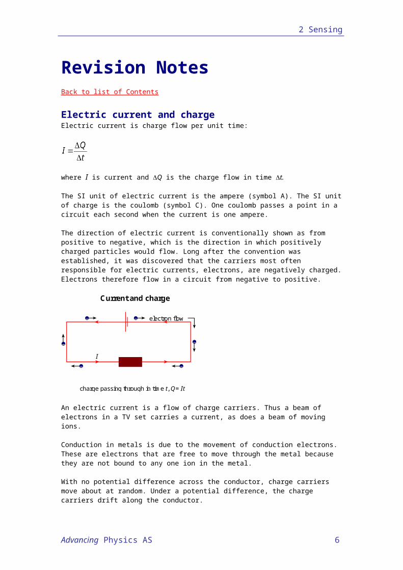
Electric current and chargeElectric current is charge flow per unit time:
where I is current and Q is the charge flow in time t.
The SI unit of electric current is the ampere (symbol A). The SI unit of charge is the coulomb (symbol C). One coulomb passes a point in a circuit each second when the current is one ampere.
The direction of electric current is conventionally shown as from positive to negative, which is the direction in which positively charged particles would flow. Long after the convention was established, it was discovered that the carriers most often responsible for electric currents, electrons, are negatively charged. Electrons therefore flow in a circuit from negative to positive.
electron flow
charge passing through in time t, Q= It
Current and charge
– –
–
––
–
I
An electric current is a flow of charge carriers. Thus a beam of electrons in a TV set carries a current, as does a beam of moving ions.
Conduction in metals is due to the movement of conduction electrons. These are electrons that are free to move through the metal because they are not bound to any one ion in the metal.
With no potential difference across the conductor, charge carriers move about at random. Under a potential difference, the charge carriers drift along the conductor.
Back to Student’s Checklist
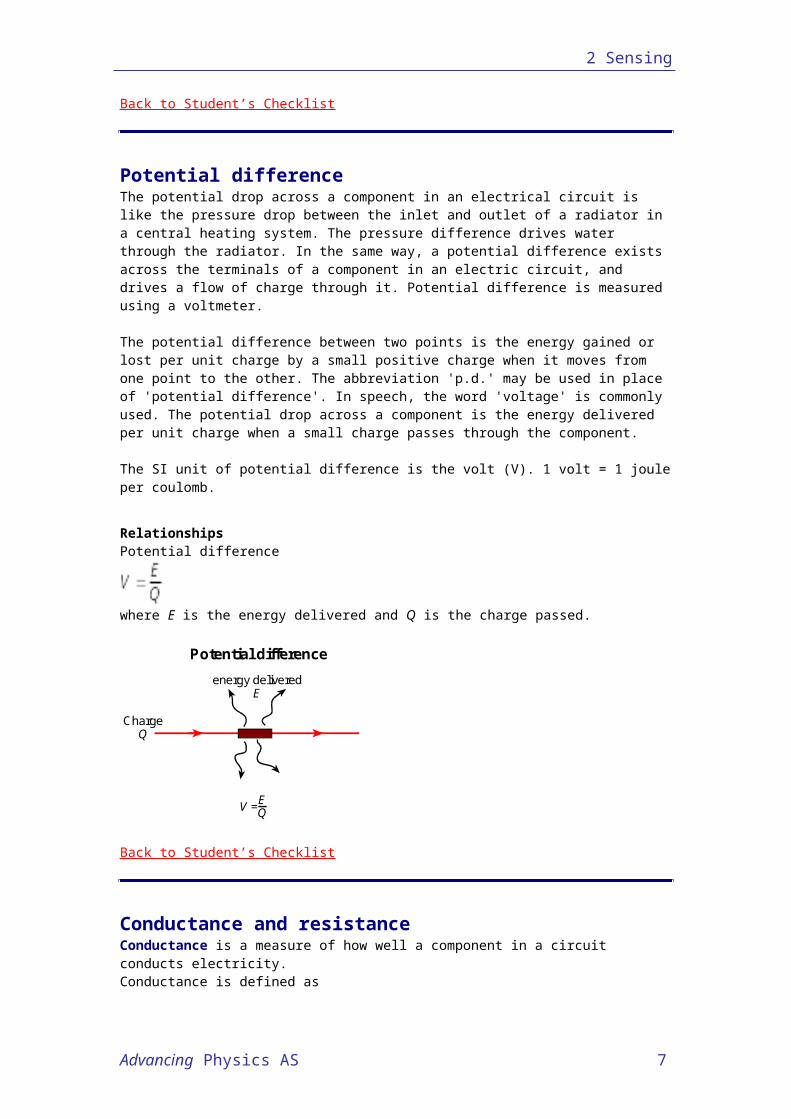
Potential differenceThe potential drop across a component in an electrical circuit is like the pressure drop between the inlet and outlet of a radiator in a central heating system. The pressure difference drives water through the radiator. In the same way, a potential difference exists across the terminals of a component in an electric circuit, and drives a flow of charge through it. Potential difference is measured using a voltmeter.
Advancing Physics AS 5
2 Sensing
The potential difference between two points is the energy gained or lost per unit charge by a small positive charge when it moves from one point to the other. The abbreviation 'p.d.' may be used in place of 'potential difference'. In speech, the word 'voltage' is commonly used. The potential drop across a component is the energy delivered per unit charge when a small charge passes through the component.
The SI unit of potential difference is the volt (V). 1 volt = 1 joule per coulomb.
RelationshipsPotential difference
where E is the energy delivered and Q is the charge passed.
energy deliveredE
ChargeQ
V =EQ
Potential difference
Back to Student’s Checklist
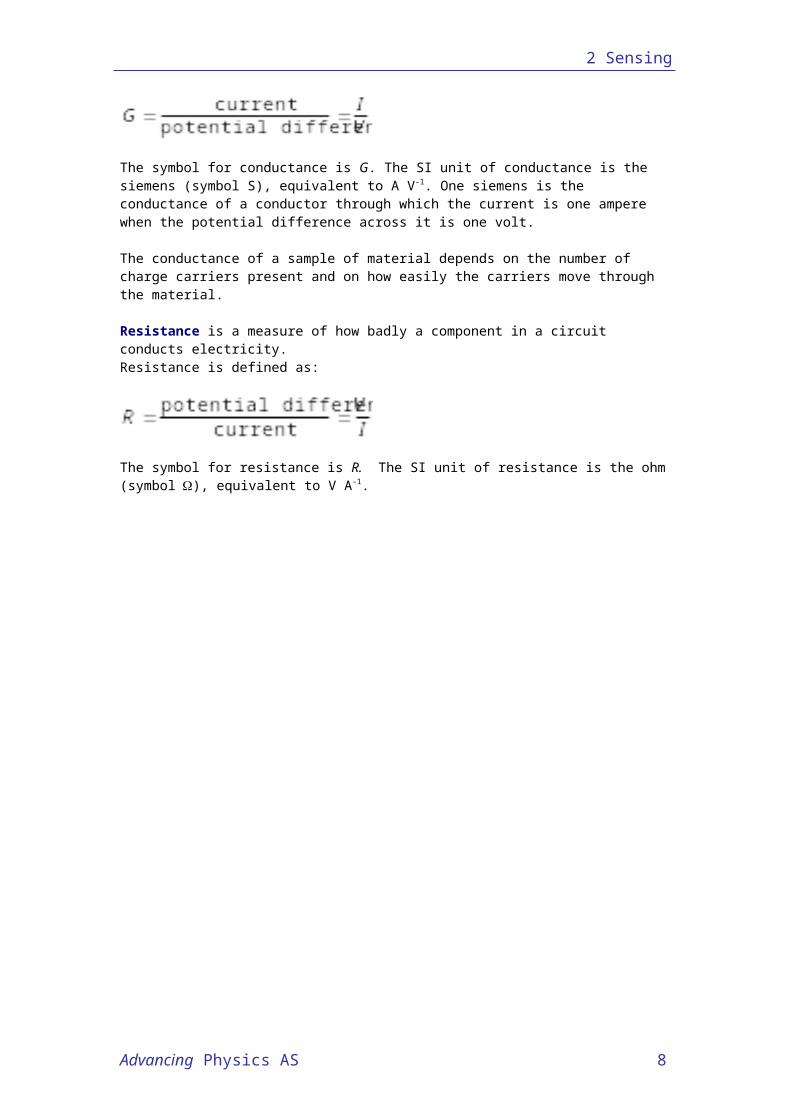
Conductance and resistanceConductance is a measure of how well a component in a circuit conducts electricity.Conductance is defined as
The symbol for conductance is G. The SI unit of conductance is the siemens (symbol S), equivalent to A V-1. One siemens is the conductance of a conductor through which the current is one ampere when the potential difference across it is one volt.
The conductance of a sample of material depends on the number of charge carriers present and on how easily the carriers move through the material.
Resistance is a measure of how badly a component in a circuit conducts electricity.Resistance is defined as:
The symbol for resistance is R. The SI unit of resistance is the ohm (symbol), equivalent to V A-1.
Advancing Physics AS 6
2 Sensing
Thus conductance and resistance are simply alternative ways of describing the same thing. Each is the reciprocal of the other.
The choice of which to use is a matter of convenience. Perhaps conductance is rather more fundamental, expressing effect (current) per unit of cause (potential difference). The term resistance unfortunately suggests that a conductor 'fights' the flow of current, when in fact the flow is mainly determined simply by whether or not there are any mobile charge carriers.
Back to Student’s Checklist
Parallel circuitIn a parallel circuit, charge flows from one point to another along alternative paths.
Circuit rules:1. The potential difference across components in parallel is the same for each
component.2. The current through a parallel combination is equal to the sum of the currents through
the individual components.
Components in parallel can be switched on or off independently by a switch in series with each component. For example, appliances connected to a ring main circuit are in parallel with each other between the live and the neutral wires of the ring main. This is so they can be switched on or off without affecting each other. Light sockets connected to a lighting circuit are also connected in parallel with each other so they can be switched on or off independently.
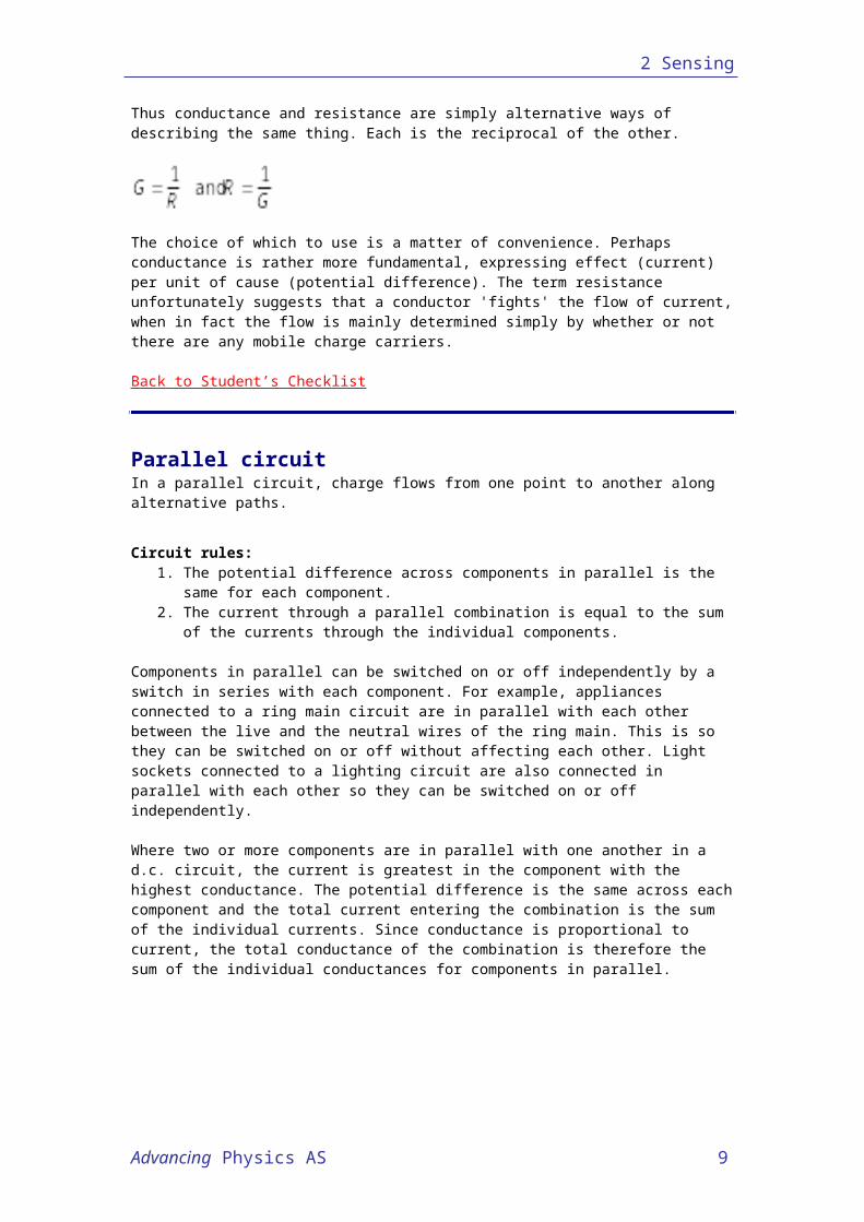
Where two or more components are in parallel with one another in a d.c. circuit, the current is greatest in the component with the highest conductance. The potential difference is the same across each component and the total current entering the combination is the sum of the individual currents. Since conductance is proportional to current, the total conductance of the combination is therefore the sum of the individual conductances for components in parallel.
G1
G2
G3
Combined conductance
G = G1+G2+G3
Conductance in parallel
Since G=1/R this can also be written:
1 / R = 1 / R1 + 1 / R2 + 1 / R3
Back to Student’s Checklist
Advancing Physics AS 7
2 Sensing
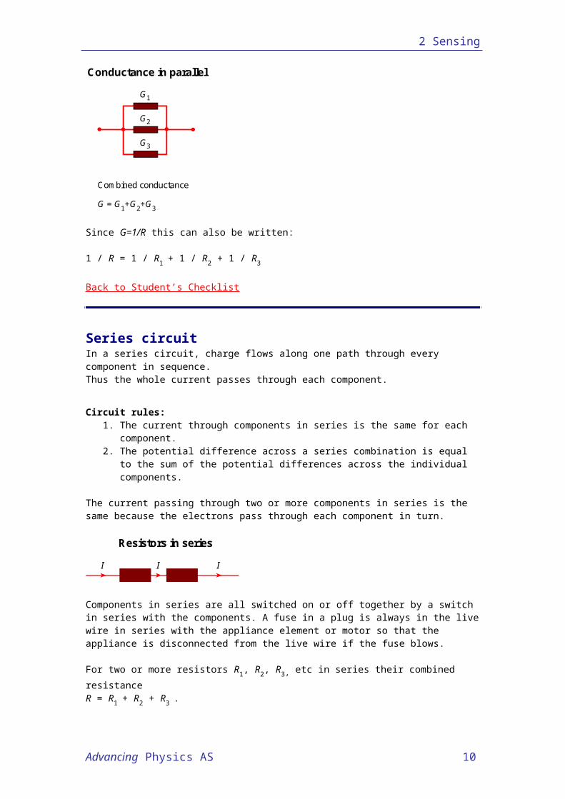
Series circuitIn a series circuit, charge flows along one path through every component in sequence.Thus the whole current passes through each component.
Circuit rules:1. The current through components in series is the same for each component.2. The potential difference across a series combination is equal to the sum of the
potential differences across the individual components.
The current passing through two or more components in series is the same because the electrons pass through each component in turn.
II I
Resistors in series
Components in series are all switched on or off together by a switch in series with the components. A fuse in a plug is always in the live wire in series with the appliance element or motor so that the appliance is disconnected from the live wire if the fuse blows.
For two or more resistors R1, R2, R3, etc in series their combined resistance R = R1 + R2 + R3 .
Because R = 1/G their combined conductance G is given by 1 / G = 1 / G1 + 1 / G2 + 1 / G3.
Back to Student’s Checklist
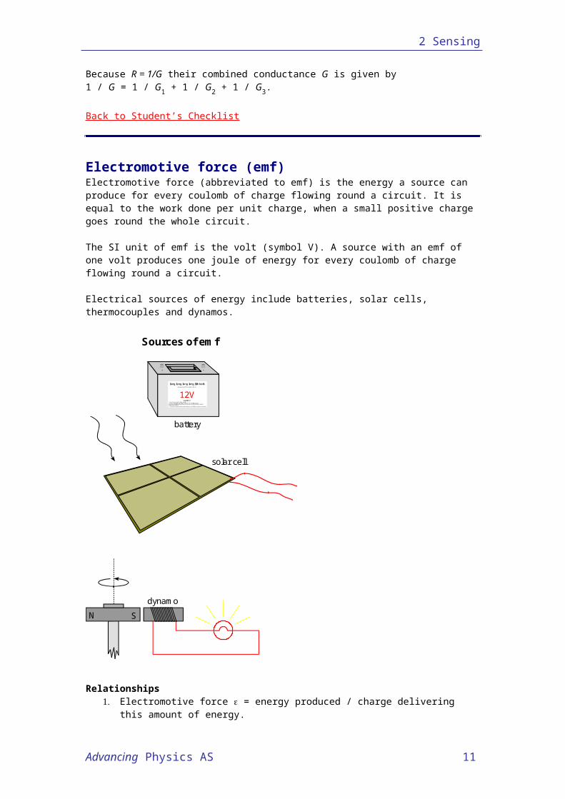
Electromotive force (emf)Electromotive force (abbreviated to emf) is the energy a source can produce for every coulomb of charge flowing round a circuit. It is equal to the work done per unit charge, when a small positive charge goes round the whole circuit.
The SI unit of emf is the volt (symbol V). A source with an emf of one volt produces one joule of energy for every coulomb of charge flowing round a circuit.
Electrical sources of energy include batteries, solar cells, thermocouples and dynamos.
Advancing Physics AS 8
2 Sensing
solar cell
N S
dynamo
Sources of emf
long long long long life batt.ga renteed to last for the duration of this CD!
12Vcaution !
1.. Never sho rt curcu it this power supply,2.. No user servicable parts, refure main tanance to a qualified enginer,except th e water fil ling up thing (thats ea sy as long as yo ur not the kind of div th atwould use tap water !!!)3.. I f consumed, seek immedia te medica l attent io n - a nd tell them to ch uck a way the key!
+ –
battery
Relationships1. Electromotive force = energy produced / charge delivering this amount of energy.2. Energy E produced by a source is given by E = Q where is the source emf and
Q is the charge delivered.3. Since the charge passing through a source in time t is Q = It, where I is the
current, then the energy produced E = It.
Back to Student’s Checklist
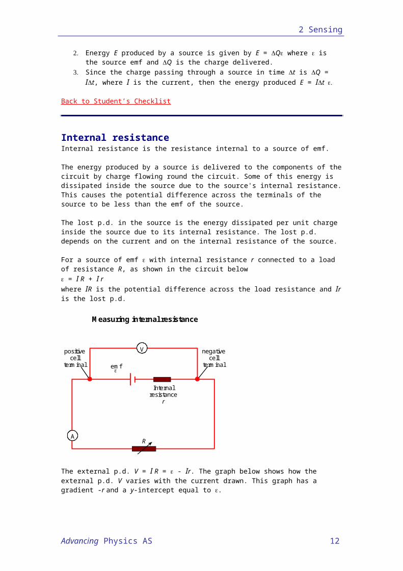
Internal resistanceInternal resistance is the resistance internal to a source of emf.
The energy produced by a source is delivered to the components of the circuit by charge flowing round the circuit. Some of this energy is dissipated inside the source due to the source's internal resistance. This causes the potential difference across the terminals of the source to be less than the emf of the source.
The lost p.d. in the source is the energy dissipated per unit charge inside the source due to its internal resistance. The lost p.d. depends on the current and on the internal resistance of the source.
For a source of emf with internal resistance r connected to a load of resistance R, as shown in the circuit below = I R + I r where IR is the potential difference across the load resistance and Ir is the lost p.d.
Advancing Physics AS 9
2 Sensing
A
V
emf
Internalresistance
r
R
positivecell
terminal
negativecell
terminal
Measuring internal resistance
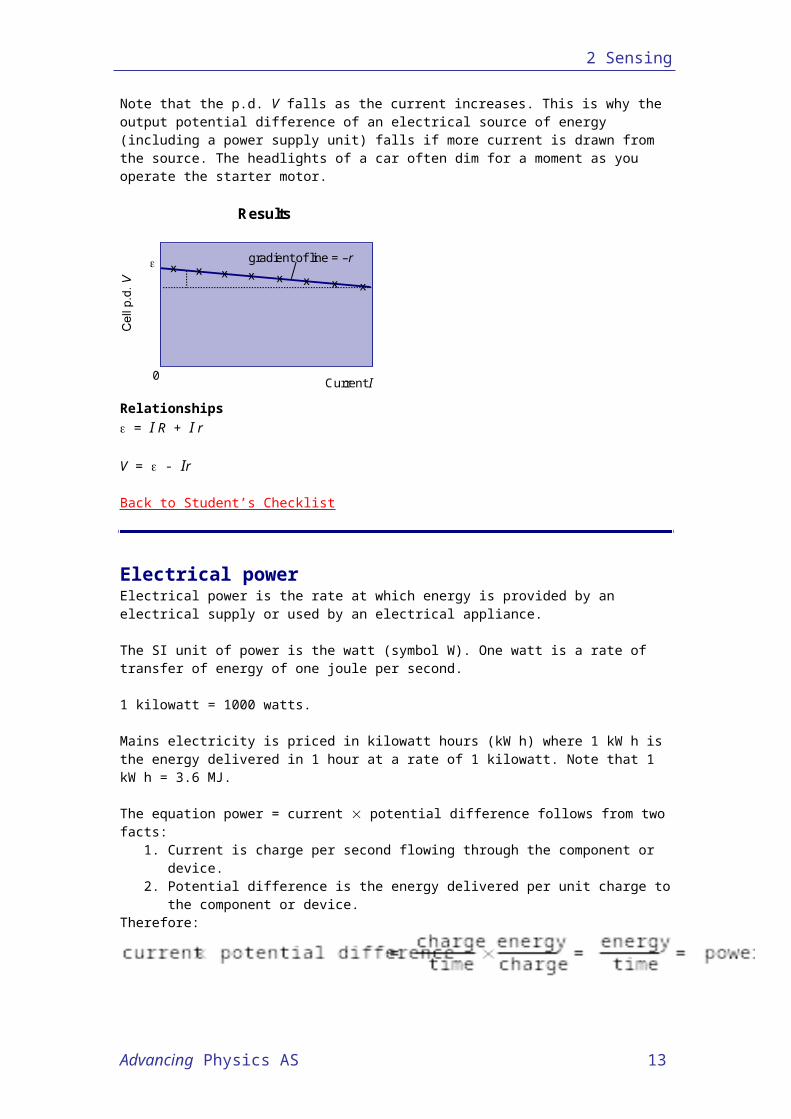
The external p.d. V = I R = - Ir. The graph below shows how the external p.d. V varies with the current drawn. This graph has a gradient -r and a y-intercept equal to .
Note that the p.d. V falls as the current increases. This is why the output potential difference of an electrical source of energy (including a power supply unit) falls if more current is drawn from the source. The headlights of a car often dim for a moment as you operate the starter motor.
0
gradient of line = –r
Current I
Results
Relationships = I R + I r
V = - Ir
Back to Student’s Checklist
Electrical powerElectrical power is the rate at which energy is provided by an electrical supply or used by an electrical appliance.
The SI unit of power is the watt (symbol W). One watt is a rate of transfer of energy of one joule per second.
1 kilowatt = 1000 watts.
Mains electricity is priced in kilowatt hours (kW h) where 1 kW h is the energy delivered in 1 hour at a rate of 1 kilowatt. Note that 1 kW h = 3.6 MJ.
Advancing Physics AS 10
2 Sensing
The equation power = current potential difference follows from two facts:1. Current is charge per second flowing through the component or device.2. Potential difference is the energy delivered per unit charge to the component or
device.Therefore:
Relationships
P = IV
Since V = IR then also:P = I2R
Alternatively, since I = V/R then:P = V2/R
Back to Student’s Checklist
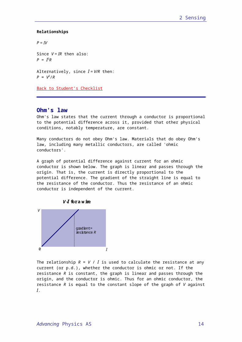
Ohm's lawOhm's law states that the current through a conductor is proportional to the potential difference across it, provided that other physical conditions, notably temperature, are constant.
Many conductors do not obey Ohm's law. Materials that do obey Ohm's law, including many metallic conductors, are called 'ohmic conductors'.
A graph of potential difference against current for an ohmic conductor is shown below. The graph is linear and passes through the origin. That is, the current is directly proportional to the potential difference. The gradient of the straight line is equal to the resistance of the conductor. Thus the resistance of an ohmic conductor is independent of the current.
0
V
gradient =resistance R
I
V-I for a wire
The relationship R = V / I is used to calculate the resistance at any current (or p.d.), whether the conductor is ohmic or not. If the resistance R is constant, the graph is linear and passes through the origin, and the conductor is ohmic. Thus for an ohmic conductor, the resistance R is equal to the constant slope of the graph of V against I.
RelationshipsR = V / I whether the conductor is ohmic or not (R not necessarily constant).
Back to Student’s Checklist
Advancing Physics AS 11
2 Sensing
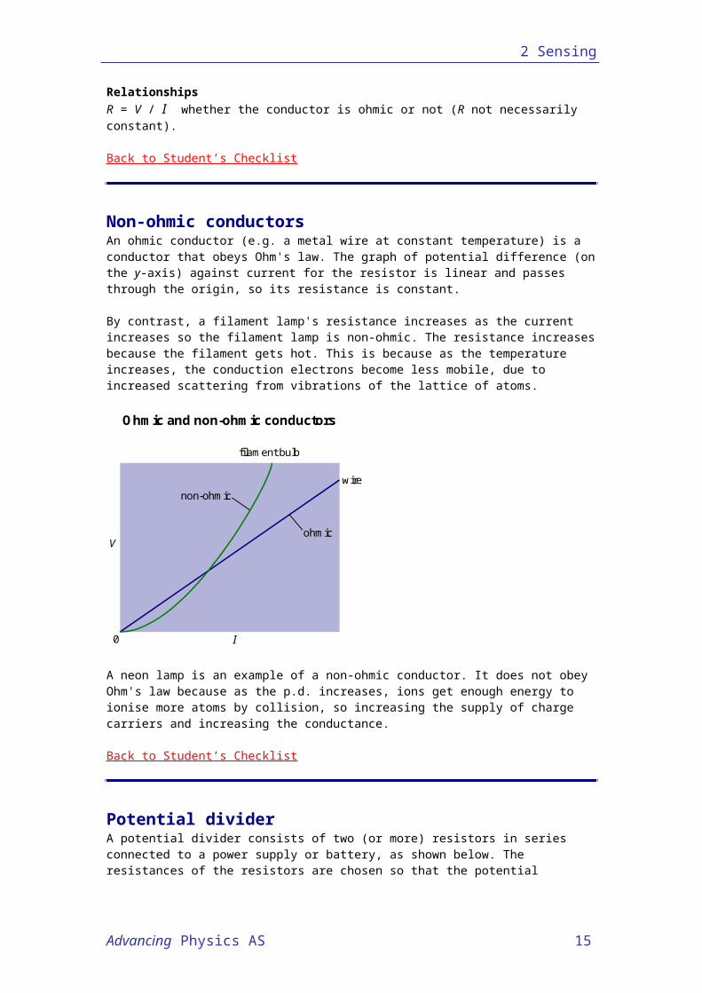
Non-ohmic conductorsAn ohmic conductor (e.g. a metal wire at constant temperature) is a conductor that obeys Ohm's law. The graph of potential difference (on the y-axis) against current for the resistor is linear and passes through the origin, so its resistance is constant.
By contrast, a filament lamp's resistance increases as the current increases so the filament lamp is non-ohmic. The resistance increases because the filament gets hot. This is because as the temperature increases, the conduction electrons become less mobile, due to increased scattering from vibrations of the lattice of atoms.
Ohmic and non-ohmic conductors
non-ohmic
ohmic
wire
filament bulb
V
I0
A neon lamp is an example of a non-ohmic conductor. It does not obey Ohm's law because as the p.d. increases, ions get enough energy to ionise more atoms by collision, so increasing the supply of charge carriers and increasing the conductance.
Back to Student’s Checklist
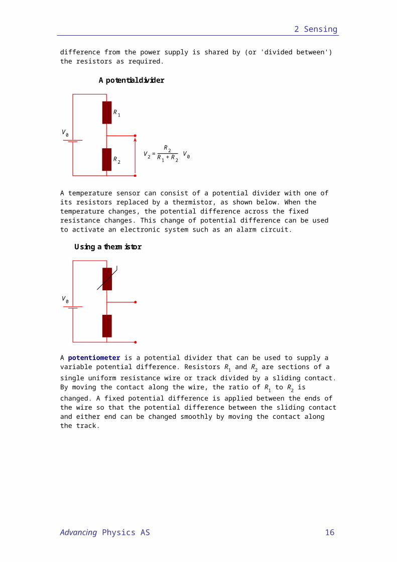
Potential dividerA potential divider consists of two (or more) resistors in series connected to a power supply or battery, as shown below. The resistances of the resistors are chosen so that the potential difference from the power supply is shared by (or 'divided between') the resistors as required.
A potential divider
R1
R2
V2 = R1 + R2
R2 V0
V0
A temperature sensor can consist of a potential divider with one of its resistors replaced by a thermistor, as shown below. When the temperature changes, the potential difference across
Advancing Physics AS 12
2 Sensing
the fixed resistance changes. This change of potential difference can be used to activate an electronic system such as an alarm circuit.
Using a thermistor
V0
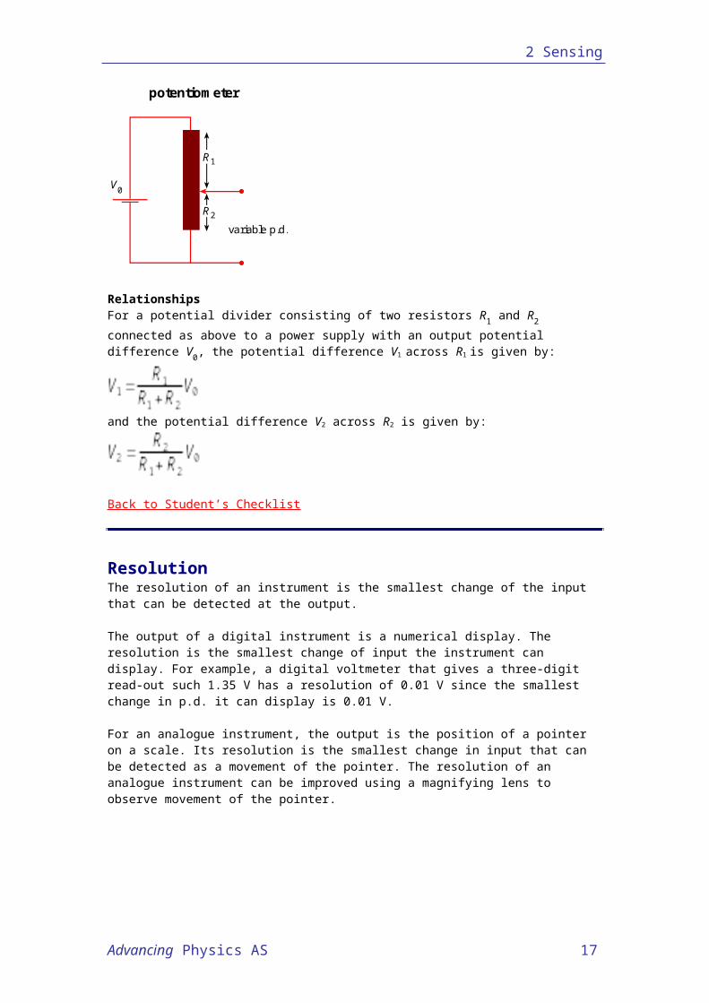
A potentiometer is a potential divider that can be used to supply a variable potential difference. Resistors R1 and R2 are sections of a single uniform resistance wire or track divided by a sliding contact. By moving the contact along the wire, the ratio of R1 to R2 is changed. A fixed potential difference is applied between the ends of the wire so that the potential difference between the sliding contact and either end can be changed smoothly by moving the contact along the track.
potentiometer
V0
variable p.d.
R1
R2
RelationshipsFor a potential divider consisting of two resistors R1 and R2 connected as above to a power supply with an output potential difference V0, the potential difference V1 across R1 is given by:
and the potential difference V2 across R2 is given by:
Back to Student’s Checklist
ResolutionThe resolution of an instrument is the smallest change of the input that can be detected at the output.
Advancing Physics AS 13
2 Sensing
The output of a digital instrument is a numerical display. The resolution is the smallest change of input the instrument can display. For example, a digital voltmeter that gives a three-digit read-out such 1.35 V has a resolution of 0.01 V since the smallest change in p.d. it can display is 0.01 V.
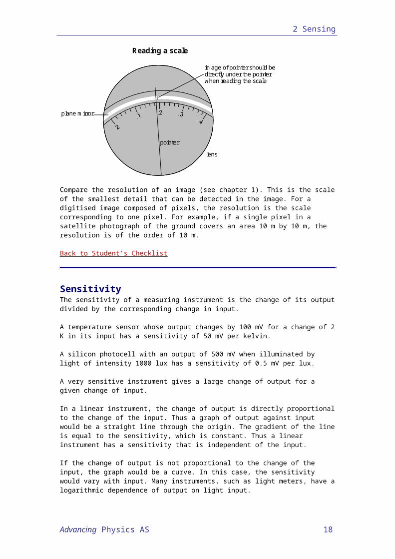
For an analogue instrument, the output is the position of a pointer on a scale. Its resolution is the smallest change in input that can be detected as a movement of the pointer. The resolution of an analogue instrument can be improved using a magnifying lens to observe movement of the pointer.
Reading a scale
plane mirror
lens
image of pointer should bedirectly under the pointerwhen reading the scale
pointer
Compare the resolution of an image (see chapter 1). This is the scale of the smallest detail that can be detected in the image. For a digitised image composed of pixels, the resolution is the scale corresponding to one pixel. For example, if a single pixel in a satellite photograph of the ground covers an area 10 m by 10 m, the resolution is of the order of 10 m.
Back to Student’s Checklist
SensitivityThe sensitivity of a measuring instrument is the change of its output divided by the corresponding change in input.
A temperature sensor whose output changes by 100 mV for a change of 2 K in its input has a sensitivity of 50 mV per kelvin.
A silicon photocell with an output of 500 mV when illuminated by light of intensity 1000 lux has a sensitivity of 0.5 mV per lux.
A very sensitive instrument gives a large change of output for a given change of input.
In a linear instrument, the change of output is directly proportional to the change of the input. Thus a graph of output against input would be a straight line through the origin. The gradient of the line is equal to the sensitivity, which is constant. Thus a linear instrument has a sensitivity that is independent of the input.
If the change of output is not proportional to the change of the input, the graph would be a curve. In this case, the sensitivity would vary with input. Many instruments, such as light meters, have a logarithmic dependence of output on light input.
Back to Student’s Checklist
Advancing Physics AS 14
2 Sensing
Advancing Physics AS 15
2 Sensing
Response timeResponse time is the time taken by a system to change after a signal initiates the change.
In a temperature-control system, the response time is the time taken for the system to respond after its temperature changes. For example, a home heating system with a response time that is too long would not start to warm the building as soon as its temperature fell below the desired level.
In an electronic measuring instrument, the response time is the time taken by the instrument to give a reading following a change in its input. If the response time is too long, the instrument would not measure changing inputs reliably. If the response time is too short, the instrument might respond to unwanted changes in input.
Reasons for slow response times include the inertia of moving parts and the thermal capacity of temperature sensors.
Back to Student’s Checklist
Systematic errorAll measurements are prone to systematic error. A systematic error is any biasing effect, in the environment, methods of observation or instruments used, which introduces error into an experiment. For example, the length of a pendulum will be in error if slight movement of the support, which effectively lengthens the string, is not allowed for.
Incorrect zeroing of an instrument leading to a zero error is an example of systematic error in instrumentation. It is important to check the zero reading during an experiment as well as at the start.
Systematic errors can change during an experiment. In this case, measurements show trends with time rather than varying randomly about a mean. The instrument is said to show drift.
Systematic errors can be reduced by checking instruments against known standards. They can also be detected by measuring already known quantities.
Constant systematic errors are very difficult to deal with, because their effects are only observable if they can be removed. Historically, many measurements in physics have turned out later to contain systematic error. In the end, to remove a systematic error is simply to make a better experiment.
Back to Student’s Checklist
Random errorRandom error has to do with small unpredictable variations in quantities.
Truly random variation may be rather rare. However, variations due to a number of minor and unrelated causes often combine to produce a result that appears to vary randomly.
Random errors can be due to uncontrollable changes in the apparatus or the environment or due to poor technique on the part of an observer. Errors can be reduced by redesigning the apparatus or by controlling the environment (e.g. the temperature). Even so, random variation can still remain. The experimenter then needs to use the extent of such variation to assess the range within which the true result may reasonably be believed to lie.
Advancing Physics AS 16
2 Sensing
First, accidental variations with known causes need to have been eliminated, and known systematic errors should have been allowed for. Then, variations of measurements around an average value are often treated as random errors.
The simplest approach is to suppose that the true result lies somewhere in the range covered by the random variation. This is a bit pessimistic, since it is more likely that the true result lies fairly near the middle of the range than near the extremes.
Back to Student’s Checklist
ThermocoupleA thermocouple consists of two dissimilar metal wires joined together. When there is a temperature difference between their two junctions, a thermoelectric emf is produced.The metals must be different and for a given temperature, the emf depends on the choice of the two metals.
Because the probe is no more than a junction between two thin wires, it can respond rapidly to change of temperature, and so can have a short response time. Because a thermocouple generates an emf directly, it is used widely in control systems.
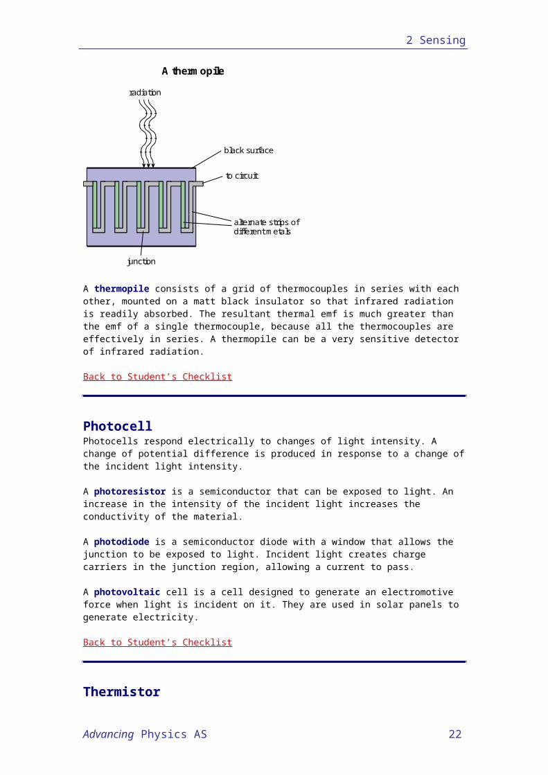
A thermopile
radiation
black surface
to circuit
alternate strips ofdifferent metals
junction
A thermopile consists of a grid of thermocouples in series with each other, mounted on a matt black insulator so that infrared radiation is readily absorbed. The resultant thermal emf is much greater than the emf of a single thermocouple, because all the thermocouples are effectively in series. A thermopile can be a very sensitive detector of infrared radiation.
Back to Student’s Checklist
PhotocellPhotocells respond electrically to changes of light intensity. A change of potential difference is produced in response to a change of the incident light intensity.
A photoresistor is a semiconductor that can be exposed to light. An increase in the intensity of the incident light increases the conductivity of the material.
Advancing Physics AS 17
2 Sensing
A photodiode is a semiconductor diode with a window that allows the junction to be exposed to light. Incident light creates charge carriers in the junction region, allowing a current to pass.
A photovoltaic cell is a cell designed to generate an electromotive force when light is incident on it. They are used in solar panels to generate electricity.
Back to Student’s Checklist
ThermistorA thermistor is a type of semiconductor resistor that has a large change of resistance with temperature.
The resistance of a thermistor most commonly decreases with temperature. But there is a type whose resistance increases with temperature.
Thermistors are used in potential dividers to supply a potential difference that varies with temperature to electronic control and measurement circuits.
Back to Student’s Checklist
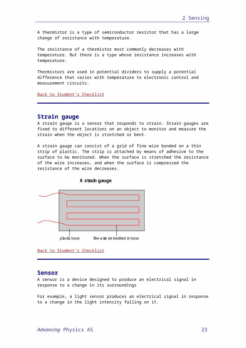
Strain gaugeA strain gauge is a sensor that responds to strain. Strain gauges are fixed to different locations on an object to monitor and measure the strain when the object is stretched or bent.
A strain gauge can consist of a grid of fine wire bonded on a thin strip of plastic. The strip is attached by means of adhesive to the surface to be monitored. When the surface is stretched the resistance of the wire increases, and when the surface is compressed the resistance of the wire decreases.
A strain gauge
plastic base fine wire embedded in base
Back to Student’s Checklist
SensorA sensor is a device designed to produce an electrical signal in response to a change in its surroundings
For example, a light sensor produces an electrical signal in response to a change in the light intensity falling on it. Many sensors rely on a change in a quantity such as resistance and so require a source of power to generate an output potential difference. These are passive sensors.
Advancing Physics AS 18
2 Sensing
Some sensors contain a component that generates a voltage in response to a change of the input variable. For example, a pressure sensor may contain a piezoelectric disc which generates a potential difference when the disc is compressed. These are active sensors.
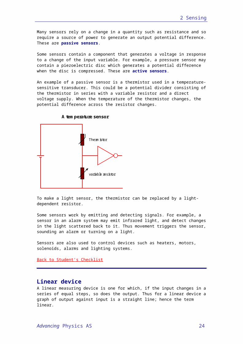
An example of a passive sensor is a thermistor used in a temperature-sensitive transducer. This could be a potential divider consisting of the thermistor in series with a variable resistor and a direct voltage supply. When the temperature of the thermistor changes, the potential difference across the resistor changes.
A temperature sensor
Thermistor
variable resistor
To make a light sensor, the thermistor can be replaced by a light-dependent resistor.
Some sensors work by emitting and detecting signals. For example, a sensor in an alarm system may emit infrared light, and detect changes in the light scattered back to it. Thus movement triggers the sensor, sounding an alarm or turning on a light.
Sensors are also used to control devices such as heaters, motors, solenoids, alarms and lighting systems.
Back to Student’s Checklist
Linear deviceA linear measuring device is one for which, if the input changes in a series of equal steps, so does the output. Thus for a linear device a graph of output against input is a straight line; hence the term linear.
Only if the output is zero for zero input does the graph pass through the origin. In this case, the output is directly proportional to the input.
A linear amplifier is one in which changes in the output voltage are in proportion to changes in the input voltage. In addition the output voltage will often be zero when the input voltage is zero.
Examples of linear devices are:1. A spring balance; the extension of the spring is directly proportional to the force
acting on the spring balance. The spring obeys Hooke's law.2. A top pan balance; the read-out is directly proportional to the weight of the object on
the balance pan.3. A moving coil meter; the deflection of the pointer from zero is directly proportional to
the current through the instrument. Therefore the scale of a moving coil meter is graduated in equal intervals.
Advancing Physics AS 19

2 Sensing
Non-linear measuring devices do not have a linear scale. Examples of non-linear devices include light intensity and sound intensity meters. Car fuel gauges also often have non-linear scales.
Back to Student’s Checklist
Advancing Physics AS 20
2 Sensing
Summary Diagrams (OHTs)Back to list of Contents
Rivers and electric currentsHere you can see how drop and flow in rivers can be used to model electric quantities.
heightdifference
energy from water as it movesstones etc on the river bottom
water current
energy to water asit goes downhill
Rivers and electric currents
electric current
energy to charge carrier as itgoes down the potential hill
energy from charge carrier asit gives energy to the material
potentialdifference
Back to Student’s Checklist
Advancing Physics AS 21
2 Sensing
Conductors in parallel and seriesHere you can see how conductance and resistance are used to describe parallel and series circuits.
I1 = G1V
I2 = G2VG=
I1+I2V
G=G1+G2
1R R1
= +1 1R2
(often used)
V2 = R2I
V1 = R1I
1G G1
= +1 1G2
(not often used)
R=R1+R2
R=V1+V2
I
I1 I2
V
equivalent to
G1 G2
Parallel
Conductors in parallel and series
V V VG
I1 + I2
Example: lamps in domestic wiring circuit
Currents add up, potential difference is the same for bothconductances add up
I
Series
V
substitute for V1, V2
I
V
V1
V2
V R
Potential differences add up, current is the same for bothresistances add upExample: potential divider
I1 + I2
R1
R2
equivalent to
substitute for I1, I2
Back to Student’s Checklist
Advancing Physics AS 22
2 Sensing
Series and parallel riversHere you can see how drop and flow in rivers can be used to model series and parallel circuits.
Parallel rivers
Series rivers
current out = sum of currents in
same drop in height
same current
total drop = sum of drops
Back to Student’s Checklist
Advancing Physics AS 23
2 Sensing
Sources and internal resistanceOpen circuit behaviour is compared with behaviour under load, for different sources of emf.
Internal resistance and emf: very high internal resistance
Source:Extremely high resistancee.g. quartz crystal
Outputemf E
Rinternalvery large
Almost no current flows, potentialdifference V across Rexternal is nearly zero
I ~ 0~
V = I Rexternal ~ 0
output
Open circuit Circuit with load Rexternal
~~~ RexternalRinternal
Internal resistance and emf: very low internal resistance
Outputemf E
Rinternal
Open circuit Circuit with load Rexternal
Almost no internal resistancePotential difference V is almost equal to E
Source:Very low resistancee.g. car battery
V = I Rexternal ~ E~
ERexternal + Rinternal
I =
very small outputRinternal 0~~ Rexternal
Advancing Physics AS 24
2 Sensing
Internal resistance and emf: moderate internal resistance
Outputemf E
Rinternal
Open circuit Circuit with load Rexternal
ERexternal + Rinternal
I =
outputRinternal
Source:Some internal resistancee.g. dry cell, photocell
V = I Rexternal = E –IRinternal
Rexternal
Back to Student’s Checklist
Advancing Physics AS 25