Embed Size (px)
Citation preview

8/18/2019 A.o. Smith Servicing Guide 320991-000
http://slidepdf.com/reader/full/ao-smith-servicing-guide-320991-000 1/72
8/18/2019 A.o. Smith Servicing Guide 320991-000
http://slidepdf.com/reader/full/ao-smith-servicing-guide-320991-000 2/72
RESIDENTIAL GAS AND ELECTRIC WATER HEATER
SERVICE HANDBOOK
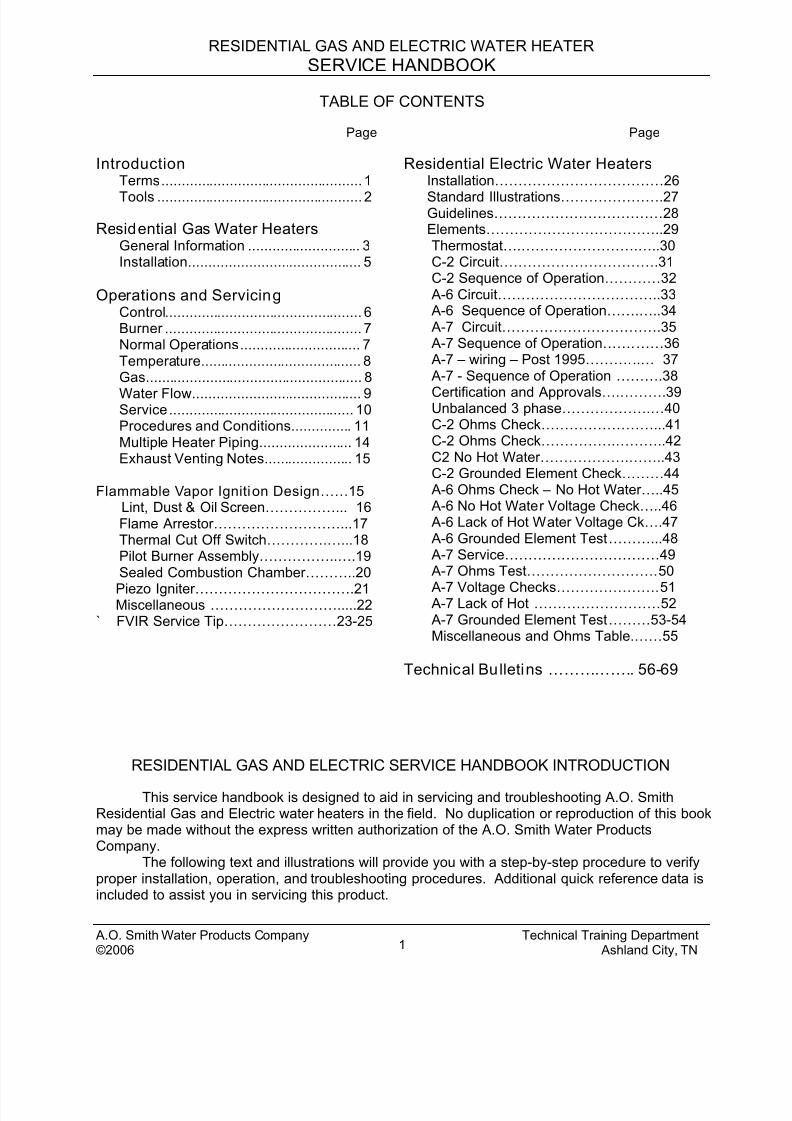
TABLE OF CONTENTS
Page
IntroductionTerms.................................................. 1
Tools ................................................... 2
Residential Gas Water HeatersGeneral Information ............................ 3 Installation........................................... 5
Operations and ServicingControl................................................. 6Burner ................................................. 7Normal Operations.............................. 7Temperature........................................ 8Gas...................................................... 8
Water Flow.......................................... 9Service.............................................. 10Procedures and Conditions............... 11Multiple Heater Piping....................... 14Exhaust Venting Notes...................... 15
Flammable Vapor Ignition Design ……15Lint, Dust & Oil Screen……………... 16Flame Arrestor………………………...17Thermal Cut Off Switch………….…...18Pilot Burner Assembly……………..….19Sealed Combustion Chamber………..20
Piezo Igniter…………………………….21Miscellaneous ……………………….....22
` FVIR Service Tip……………………23-25
Page
Residential Electric Water HeatersInstallation………………………………26
Standard Illustrations………………….27Guidelines………………………………28Elements………………………………..29Thermostat….…………………….…..30C-2 Circuit…………………………….31C-2 Sequence of Operation…………32 A-6 Circuit……………………………..33 A-6 Sequence of Operation…….…..34 A-7 Circuit…………………………….35 A-7 Sequence of Operation…….……36 A-7 – wiring – Post 1995………...… 37 A-7 - Sequence of Operation ……….38
Certification and Approvals….……….39Unbalanced 3 phase……………….…40C-2 Ohms Check……………………...41C-2 Ohms Check…………….………..42C2 No Hot Water……………….……..43C-2 Grounded Element Check………44 A-6 Ohms Check – No Hot Water…..45 A-6 No Hot Water Voltage Check…..46 A-6 Lack of Hot Water Voltage Ck….47 A-6 Grounded Element Test………...48 A-7 Service……………………………49 A-7 Ohms Test……………………….50
A-7 Voltage Checks………………….51 A-7 Lack of Hot ………………………52 A-7 Grounded Element Test………53-54Miscellaneous and Ohms Table.……55
Technical Bulletins …………….. 56-69
RESIDENTIAL GAS AND ELECTRIC SERVICE HANDBOOK INTRODUCTION
This service handbook is designed to aid in servicing and troubleshooting A.O. SmithResidential Gas and Electric water heaters in the field. No duplication or reproduction of this bookmay be made without the express written authorization of the A.O. Smith Water ProductsCompany.
The following text and illustrations will provide you with a step-by-step procedure to verifyproper installation, operation, and troubleshooting procedures. Additional quick reference data isincluded to assist you in servicing this product.
A.O. Smith Water Products Company Technical Training Department©2006 Ashland City, TN1
8/18/2019 A.o. Smith Servicing Guide 320991-000
http://slidepdf.com/reader/full/ao-smith-servicing-guide-320991-000 3/72
RESIDENTIAL GAS AND ELECTRIC WATER HEATER
SERVICE HANDBOOK
The information contained in this handbook is designed to answer commonly facedsituations encountered in the operation of the Residential Gas and Electric product line and is notmeant to be all-inclusive. If you are experiencing a problem not covered in this handbook, pleasecontact the A.O. Smith Technical Information Center at 1-800-527-1953 or your local A.O. SmithWater Products Company representative for further assistance. Additional information is alsoavailable on the web site www.aosmithwaterheaters.com. This handbook is intended for use by
licensed plumbing professionals and reference should be made to the instructional manualaccompanying the product. This handbook contains supplemental information to the ResidentialGas and Electric instructional manual.
Qualifications
Tools Required:
For servicing gas models: • Cross top screw driver• 3/8, 7/16, ¾ inch open end wrenches
• 3/16 inch Allen wrench• 11/16 inch – 6 point – socket – for anode removal• set of marked drill bits• electrical multimeter• gas pressure gauge or monometer• water pressure gauge• thermometer• tubing cutter if pilot tube is to be replaced• hose – to drain tank• container – to measure gallons per minute flow
For servicing electric models: • 1 1/16 inch – 6 point – socket (for anode removal)• 1 ½ inch deep socket – to remove an element• electrical multimeter• water pressure gauge• thermometer• hose – to drain tank• container – to measure gallons per minute flow
Rev 1 adds Technical Bul letinsRev 2 corrects illustration errorsRev 3 adds FVIR (C3) Technology product information2005 printing – revised coverRev 4 Added FVIR cleaning instruc tions
A.O. Smith Water Products Company Technical Training Department©2006 Ashland City, TN2
8/18/2019 A.o. Smith Servicing Guide 320991-000
http://slidepdf.com/reader/full/ao-smith-servicing-guide-320991-000 4/72
RESIDENTIAL GAS AND ELECTRIC WATER HEATER
SERVICE HANDBOOK
GENERAL SECTION
MISCELLANEOUS INFORMATION
Draw efficiency is the quantity of hot water available to the consumer before the outlet watertemperature decreases 25 degrees F. A 40 gallon water heater will typically provide 70% (28
gallons) of this “usable” hot water. The burner or elements are allowed to operate during this test.Incoming, cold water mixes the remaining stored water below this 25 degree limitation.
Energy Factor is an indicator of the combined thermal efficiency and standby efficiency of a
water heater. The higher the energy factor, the more efficient the water heater will be.
Recovery rate is the amount of water that is heated to a set temperature, per hour. An example
might be that a water heater has a recovery rate of 30 gallons of water per hour at 80 degree F.(Fahrenheit) temperature rise.
“ R” Value is a measure of the resistance of a substance to heat flow.
Thermal efficiency is approximately the amount of generated BTU (British Thermal Units),
which enters the water. A percentage of the total BTU passes out through the vent piping.
Temperature r ise is the increase in the temperature from its coldest “inlet” water temperature tothe desired hot (outlet) setting. Typically this is assumed to be 40 degrees entering water, 120degrees desired stored water or 80 degrees “temperature rise.”
Standby effic iency – the water heater’s ability to contain heat in the tank. A minimum of tank
water heat loss per hour is desired.Sample: temperature change = Btu/h loss/ square foot of tank surface
“R” value
Water cannot (for all practical purposes) be compressed.
Water expands when it is heated.
Water Hammer – is a concussion of moving water against the sides of a containing pipe or vesselon a sudden stoppage of flow.EX: 1/2 “copper pipe, 5GPM flow (7.2ft/sec.) – stop. Pressure rise of approximately 412 PSI.
3/4” copper pipe, 5GPM flow (3.3ft/sec) – stop. Pressure rise of approximately 188 PSI
Minerals and gases will separate from water as temperature increases.
Formulas:
BTU (British Thermal Unit) is the heat required to raise 1 pound of water 1°F1 BTU = 252 cal = 0.252 kcal
1 cal = 4.187 JoulesBTU X 1.055 = Kilo Joules
BTU divided by 3,413 = Kilowatts
To convert from Fahrenheit to Centigrade: (° F – 32) times 5/9, or .556, equals degrees C.
A.O. Smith Water Products Company Technical Training Department©2006 Ashland City, TN3
8/18/2019 A.o. Smith Servicing Guide 320991-000
http://slidepdf.com/reader/full/ao-smith-servicing-guide-320991-000 5/72
RESIDENTIAL GAS AND ELECTRIC WATER HEATER
SERVICE HANDBOOK
One gallon of (120 ° F, 49 °C) water weighs approximately 8.25 pounds.
Pounds X .45359 = KilogramGallons X 3.7854 = Liters
% of Hot = (Mixed Temp. – Cold) divided by (Hot Temp. – Cold)
General Section – continued
% Thermal Efficiency = (GPH X 8.25 X Temp. Rise X 1.0) divided by BTU/H Input
BTU Output = GPH X 8.25 X Temp. Rise X 1.0
GPH = (BTU/H Input X % Eff.) divided by (Temp. Rise X 8.25)
One cubic foot of Natural Gas contains about 1000 BTU of heat.
One “ therm” is equal to 100,000 BTU
One cubic foot of Propane Gas contains about 2500 BTU of heat.
One gallon of Propane gas contains about 91,250 BTU of heat.
One pound of Propane gas contains about 21,600 BTU of heat.
One pound of gas pressure is equal to 27.7 inches water column pressureInches of Water Column X .036091 = PSIInches of Water Column X .073483 = Inches of Mercury (Hg.)
Centimeters = Inches X 2.54
MM (millimeters) =Inches X 25.4
Meters = Inches X .0254
Doubling the diameter of a pipe will increase its flow capacity (approximately) 5.3 times.
CONSTRUCTION: Tank is constructed of steel.
The inside of the tank is constructed of a glass lining bonded to the steel. This prevents water
to metal contact and rusting of the tank.
An anode rod will be installed within the tank. The hex-head plug end of the anode is visible onthe top of the water heater. This metal rod offers secondary protection of the tank againstcorrosion where the application of glass is not possible (threaded tank openings). These areaswill have small areas of water to metal contact.
All water heaters will contain at least one thermostat (to operate the heater) and one highlimit (to prevent water temperatures approaching the “steam” level).
A.O. Smith Water Products Company Technical Training Department©2006 Ashland City, TN4

8/18/2019 A.o. Smith Servicing Guide 320991-000
http://slidepdf.com/reader/full/ao-smith-servicing-guide-320991-000 6/72
RESIDENTIAL GAS AND ELECTRIC WATER HEATER
SERVICE HANDBOOK
INSTALLATION OF RESIDENTIAL GAS WATER HEATER
Typical Modeland RatingPlate Location
Union
Minimum4.5” w.c. –Natural Gas
11.0” w.c. Propane Gas
Maximum Gas Supply
13.8” w.c. or ½ PSI
Ai r Is Drawn In ForCombustion. Keep
Area Clean And FreeFrom Flammables And
Flammable Vapors
Inner andOuter Doors –Reinstall After
Lighting Pilot.
Drain
Safety Pan – Piped to
Drain
Thermostat –Recommending
setting of 125
F.
Temperature andpressure relief valvetube piped to within 6”
of drain.
WaterShut Off
Valve
Temperature AndPressure ReliefValve – Do Not
Reuse Old Valve.
Expansion TankPressurize to EqualSupply Water
Pressure
See Manual andLabels For Installation
Clearances
Union
Exhaust Vent to
Outside of Building
Installation Must Follow Local Codes and Instruction Manual Guidelines
A.O. Smith Water Products Company Technical Training Department©2006 Ashland City, TN5
8/18/2019 A.o. Smith Servicing Guide 320991-000
http://slidepdf.com/reader/full/ao-smith-servicing-guide-320991-000 7/72
RESIDENTIAL GAS AND ELECTRIC WATER HEATER
SERVICE HANDBOOK
RESIDENTAL GAS WATER HEATER SERVICE
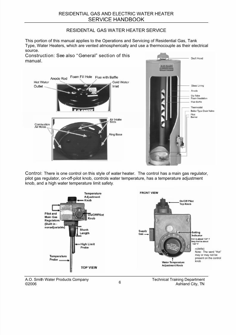
This portion of this manual applies to the Operations and Servicing of Residential Gas, TankType, Water Heaters, which are vented atmospherically and use a thermocouple as their electricalsource.
Construction: See also “General” section of thismanual.
Control: There is one control on this style of water heater. The control has a main gas regulator,pilot gas regulator, on-off-pilot knob, controls water temperature, has a temperature adjustmentknob, and a high water temperature limit safety.
σ(delta)Note: The word “Hot”may or may not bepresent on the controlknob
A.O. Smith Water Products Company Technical Training Department©2006 Ashland City, TN6
8/18/2019 A.o. Smith Servicing Guide 320991-000
http://slidepdf.com/reader/full/ao-smith-servicing-guide-320991-000 8/72
RESIDENTIAL GAS AND ELECTRIC WATER HEATER
SERVICE HANDBOOK
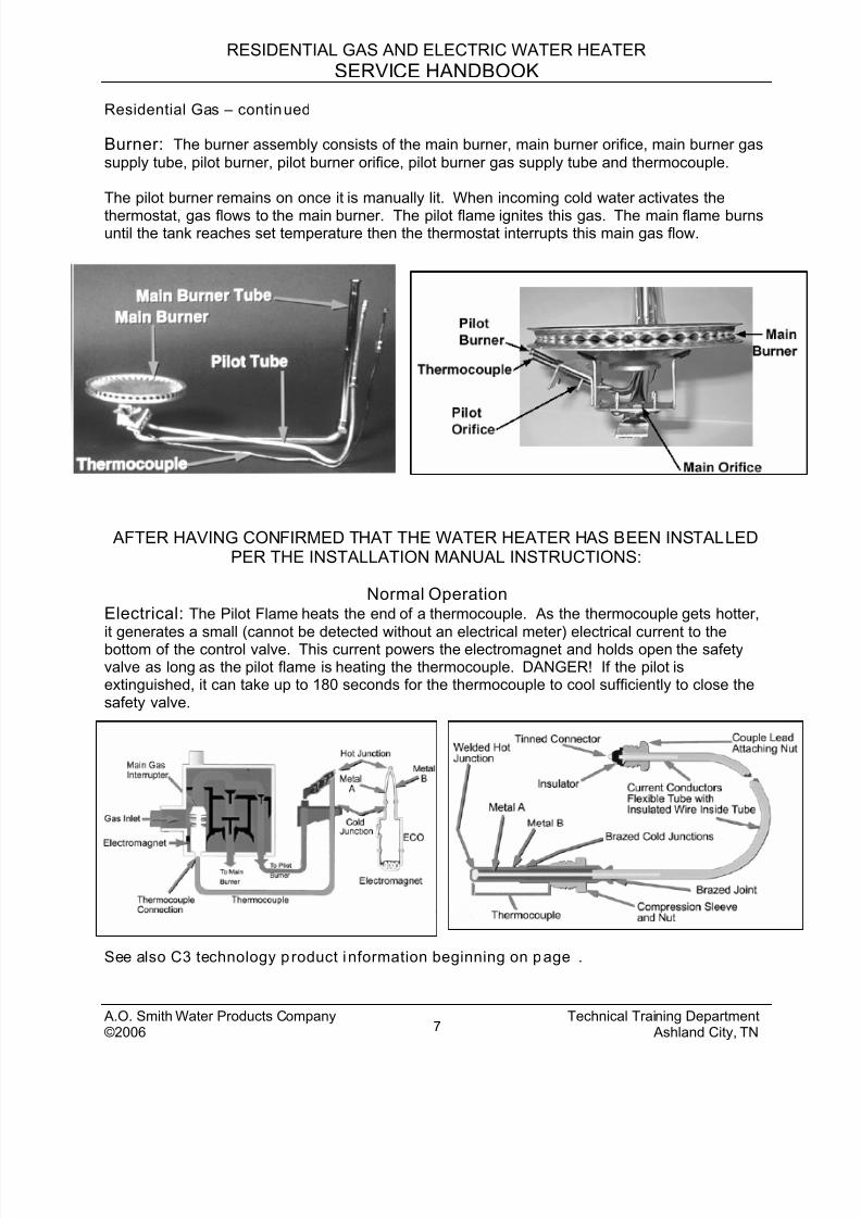
Residential Gas – continued
Burner: The burner assembly consists of the main burner, main burner orifice, main burner gas
supply tube, pilot burner, pilot burner orifice, pilot burner gas supply tube and thermocouple.
The pilot burner remains on once it is manually lit. When incoming cold water activates the
thermostat, gas flows to the main burner. The pilot flame ignites this gas. The main flame burnsuntil the tank reaches set temperature then the thermostat interrupts this main gas flow.
AFTER HAVING CONFIRMED THAT THE WATER HEATER HAS BEEN INSTALLEDPER THE INSTALLATION MANUAL INSTRUCTIONS:
Normal OperationElectrical: The Pilot Flame heats the end of a thermocouple. As the thermocouple gets hotter,
it generates a small (cannot be detected without an electrical meter) electrical current to thebottom of the control valve. This current powers the electromagnet and holds open the safetyvalve as long as the pilot flame is heating the thermocouple. DANGER! If the pilot isextinguished, it can take up to 180 seconds for the thermocouple to cool sufficiently to close thesafety valve.
See also C3 technology p roduct information beginning on page .
A.O. Smith Water Products Company Technical Training Department©2006 Ashland City, TN7
8/18/2019 A.o. Smith Servicing Guide 320991-000
http://slidepdf.com/reader/full/ao-smith-servicing-guide-320991-000 9/72
RESIDENTIAL GAS AND ELECTRIC WATER HEATER
SERVICE HANDBOOK
Resident ial Gas – continued
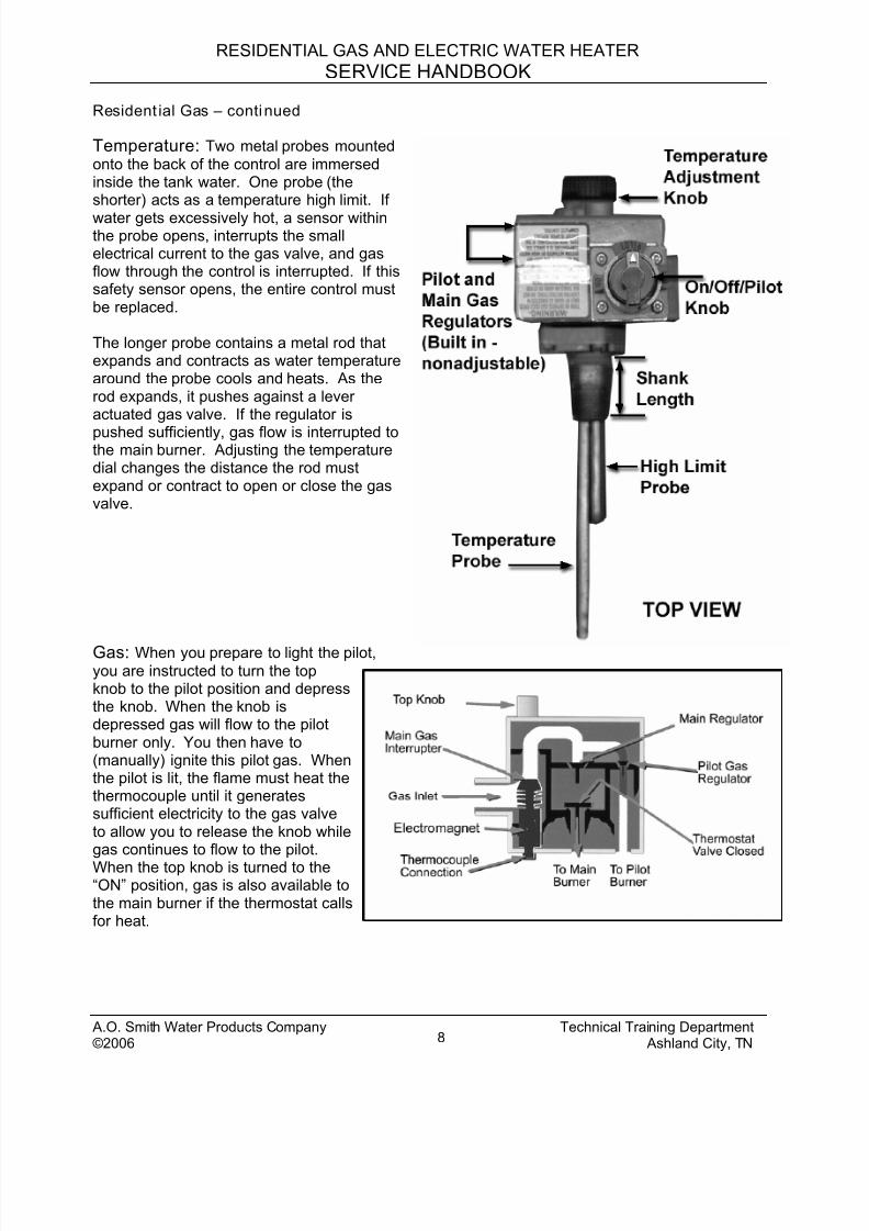
Temperature: Two metal probes mounted
onto the back of the control are immersedinside the tank water. One probe (theshorter) acts as a temperature high limit. If
water gets excessively hot, a sensor withinthe probe opens, interrupts the smallelectrical current to the gas valve, and gasflow through the control is interrupted. If thissafety sensor opens, the entire control mustbe replaced.
The longer probe contains a metal rod thatexpands and contracts as water temperaturearound the probe cools and heats. As therod expands, it pushes against a leveractuated gas valve. If the regulator is
pushed sufficiently, gas flow is interrupted tothe main burner. Adjusting the temperaturedial changes the distance the rod mustexpand or contract to open or close the gasvalve.
Gas: When you prepare to light the pilot,you are instructed to turn the topknob to the pilot position and depressthe knob. When the knob isdepressed gas will flow to the pilotburner only. You then have to(manually) ignite this pilot gas. Whenthe pilot is lit, the flame must heat thethermocouple until it generatessufficient electricity to the gas valveto allow you to release the knob whilegas continues to flow to the pilot.
When the top knob is turned to the“ON” position, gas is also available tothe main burner if the thermostat callsfor heat.
A.O. Smith Water Products Company Technical Training Department©2006 Ashland City, TN8
8/18/2019 A.o. Smith Servicing Guide 320991-000
http://slidepdf.com/reader/full/ao-smith-servicing-guide-320991-000 10/72
RESIDENTIAL GAS AND ELECTRIC WATER HEATER
SERVICE HANDBOOK
Residential Gas - continued
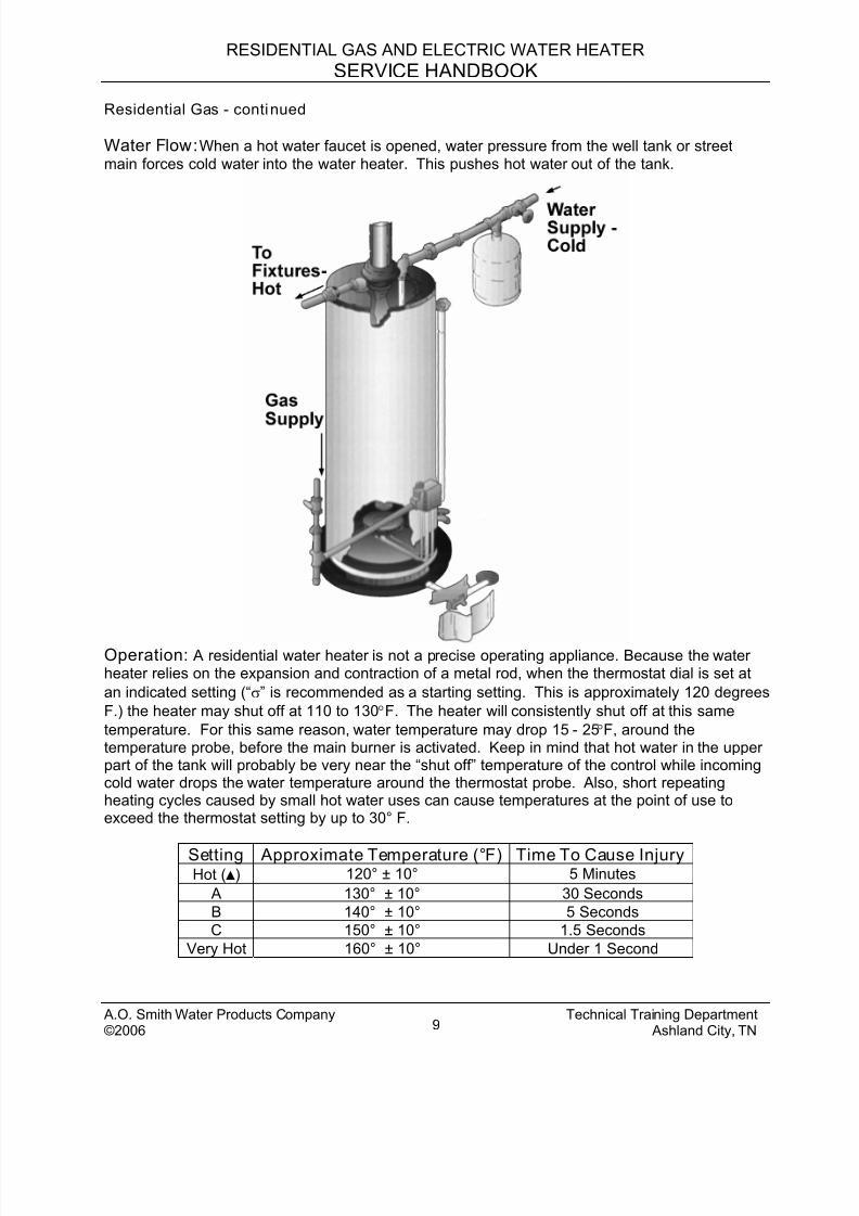
Water Flow: When a hot water faucet is opened, water pressure from the well tank or street
main forces cold water into the water heater. This pushes hot water out of the tank.
Operation: A residential water heater is not a precise operating appliance. Because the waterheater relies on the expansion and contraction of a metal rod, when the thermostat dial is set at
an indicated setting (“σ” is recommended as a starting setting. This is approximately 120 degrees
F.) the heater may shut off at 110 to 130° F. The heater will consistently shut off at this same
temperature. For this same reason, water temperature may drop 15 - 25° F, around thetemperature probe, before the main burner is activated. Keep in mind that hot water in the upperpart of the tank will probably be very near the “shut off” temperature of the control while incomingcold water drops the water temperature around the thermostat probe. Also, short repeatingheating cycles caused by small hot water uses can cause temperatures at the point of use toexceed the thermostat setting by up to 30° F.
Setting Approximate Temperature (°F) Time To Cause InjuryHot () 120° ± 10° 5 Minutes
A 130° ± 10° 30 Seconds
B 140° ± 10° 5 Seconds
C 150° ± 10° 1.5 Seconds
Very Hot 160° ± 10° Under 1 Second
A.O. Smith Water Products Company Technical Training Department©2006 Ashland City, TN9
8/18/2019 A.o. Smith Servicing Guide 320991-000
http://slidepdf.com/reader/full/ao-smith-servicing-guide-320991-000 11/72
RESIDENTIAL GAS AND ELECTRIC WATER HEATER
SERVICE HANDBOOK
Resident ial Gas - continued
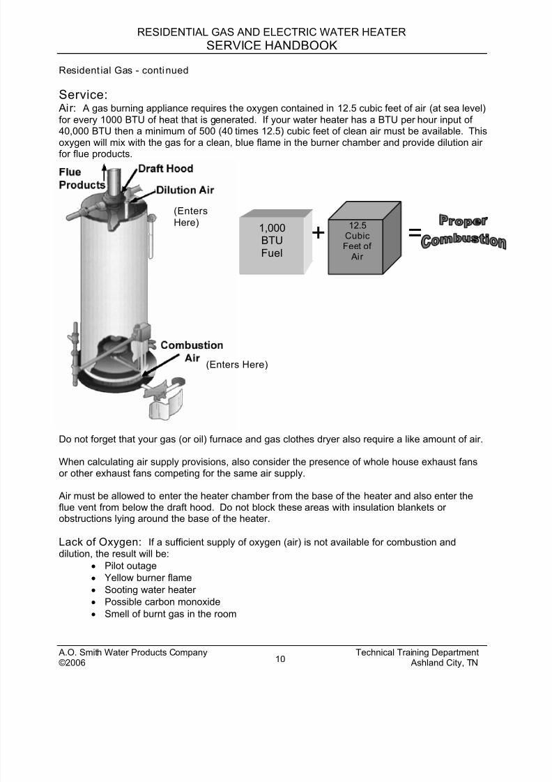
Service: Air: A gas burning appliance requires the oxygen contained in 12.5 cubic feet of air (at sea level)
for every 1000 BTU of heat that is generated. If your water heater has a BTU per hour input of40,000 BTU then a minimum of 500 (40 times 12.5) cubic feet of clean air must be available. Thisoxygen will mix with the gas for a clean, blue flame in the burner chamber and provide dilution airfor flue products.
A.O. Smith Water Products Company Technical Training Department©2006 Ashland City, TN10
12.5CubicFeet of
Air
+1,000BTUFuel
(Enters Here)
(Enters
Here)
=
Do not forget that your gas (or oil) furnace and gas clothes dryer also require a like amount of air.
When calculating air supply provisions, also consider the presence of whole house exhaust fansor other exhaust fans competing for the same air supply.
Air must be allowed to enter the heater chamber from the base of the heater and also enter theflue vent from below the draft hood. Do not block these areas with insulation blankets orobstructions lying around the base of the heater.
Lack of Oxygen: If a sufficient supply of oxygen (air) is not available for combustion and
dilution, the result will be:
• Pilot outage
• Yellow burner flame
• Sooting water heater
• Possible carbon monoxide
• Smell of burnt gas in the room
8/18/2019 A.o. Smith Servicing Guide 320991-000
http://slidepdf.com/reader/full/ao-smith-servicing-guide-320991-000 12/72
RESIDENTIAL GAS AND ELECTRIC WATER HEATER
SERVICE HANDBOOK
Residential Gas – continuedThe instruction manual gives guidelines under “Air Requirements” and “Unconfined “ or “ConfinedSpace” sections. If you want to test for a lack of air:
1. Turn on every appliance and fan that exhausts air from the utility room and/or house.Make sure all windows and doors are closed, as well as chimney dampers.
2. Open a hot water faucet so that the main burner will ignite
3. Remove the outer door of the water heater – not the inner door4. Monitor the flame characteristics for several minutes
If the flame begins to “yellow” open a door or window, to the outdoors, to see if additional aircorrects this back to blue. If it does, the room needs more air supply. Perform draft test at drafthood of water heater with match or smoke source to verify.
A.O. Smith Water Products Company Technical Training Department©2006 Ashland City, TN11
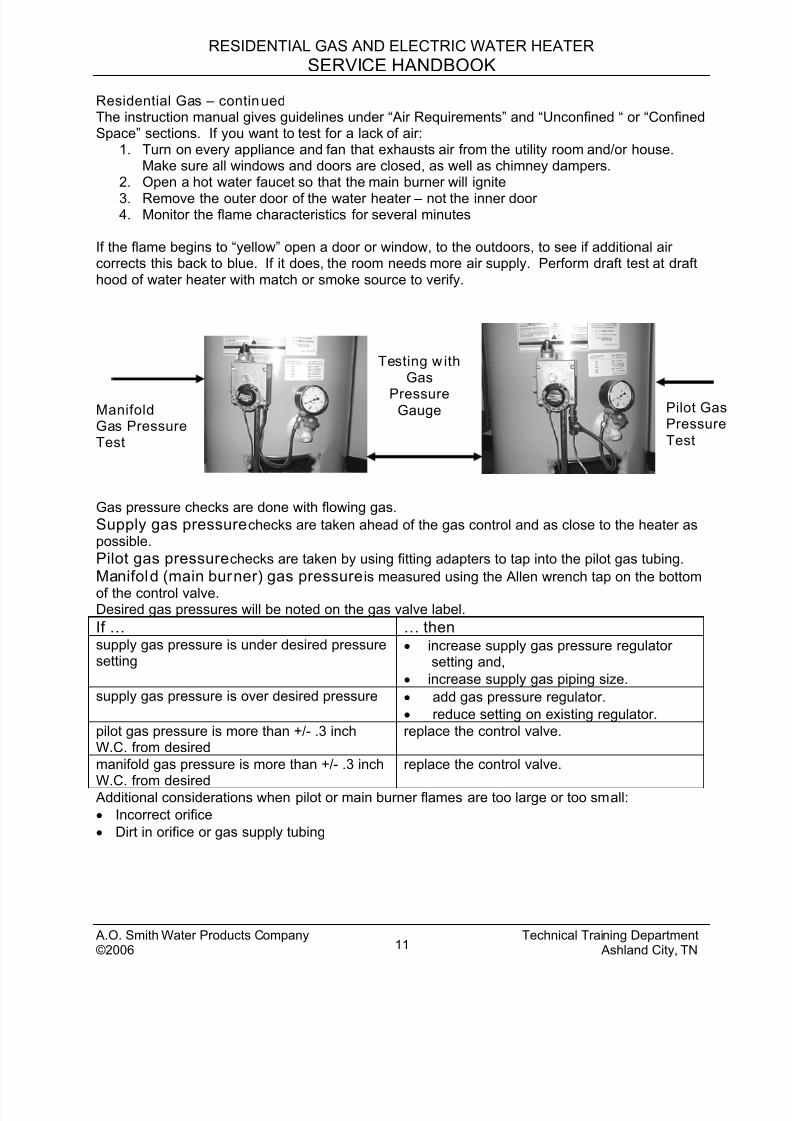
ManifoldGas PressureTest
Testing w ithGas
PressureGauge Pilot Gas
Pressure
Test
Gas pressure checks are done with flowing gas.
Supply gas pressure checks are taken ahead of the gas control and as close to the heater aspossible.
Pilot gas pressure checks are taken by using fitting adapters to tap into the pilot gas tubing.
Manifold (main burner) gas pressure is measured using the Allen wrench tap on the bottom
of the control valve.Desired gas pressures will be noted on the gas valve label.
If … … thensupply gas pressure is under desired pressuresetting
• increase supply gas pressure regulatorsetting and,
• increase supply gas piping size.
supply gas pressure is over desired pressure • add gas pressure regulator.
• reduce setting on existing regulator.
pilot gas pressure is more than +/- .3 inchW.C. from desired
replace the control valve.
manifold gas pressure is more than +/- .3 inch
W.C. from desired
replace the control valve.
Additional considerations when pilot or main burner flames are too large or too small:
• Incorrect orifice
• Dirt in orifice or gas supply tubing

8/18/2019 A.o. Smith Servicing Guide 320991-000
http://slidepdf.com/reader/full/ao-smith-servicing-guide-320991-000 13/72
RESIDENTIAL GAS AND ELECTRIC WATER HEATER
SERVICE HANDBOOK
Resident ial Gas - continued
Sooting causes:
If … … thenthe burner is clean but the chamber and/or flueare sooted
check for lack of supply air.
the main burner, chamber and flue are sooted check the following:• incorrect orifice• excessive gas pressure• loose main burner• cross threaded orifice• gas control valve gas seepage• loose gas connection in burner assembly.
Electrical Testing
TO GROUND
This type of water heater has its own electricalgenerating system.
When two dissimilar metals are joined togetherand this joint is heated, a small, electrical currentwill be produced. A thermocouple uses thisscience.
Thermocouple output test
Procedures/Conditions:Meter set for DC millivolt testingTest from lower ECO (emergency cut off or energy cut off) solder joint to ground.Note: If pilot will not stay lit, manually hold the top knob down in the pilot position. This allowsgas to flow to the pilot. Light the pilot and continue to hold this knob down while conducting thetest.
If … … thenreading test of at least 13 MV is not present • check that flame contacts end ofthermocouple
• replace thermocouple.
reading test of at least 13 MV is present continue to next test.
A.O. Smith Water Products Company Technical Training Department©2006 Ashland City, TN12
8/18/2019 A.o. Smith Servicing Guide 320991-000
http://slidepdf.com/reader/full/ao-smith-servicing-guide-320991-000 14/72
RESIDENTIAL GAS AND ELECTRIC WATER HEATER
SERVICE HANDBOOK
Residential Gas - continuedElectrical Testing– continued
Millivolt dropout test through copper magnet winding and ECO (Emergency Cut Off)
Procedure: Move meter probe to upper ECO solder joint and ground
If … … thenreading of at least 10 MV is not present replace the control valve.
reading of more than 10 MV is present but,gas to the pilot shuts off each time knob isreleased
replace the control valve.
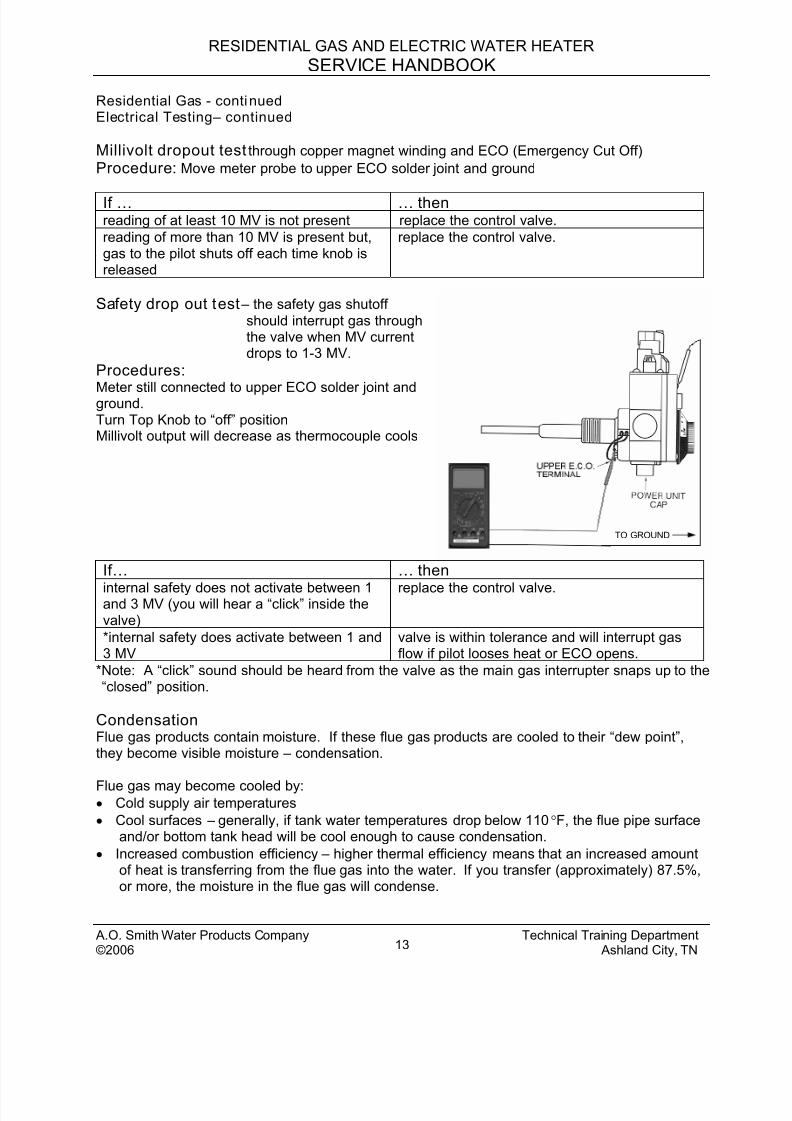
Safety drop out test – the safety gas shutoff
should interrupt gas throughthe valve when MV currentdrops to 1-3 MV.
Procedures:
Meter still connected to upper ECO solder joint andground.Turn Top Knob to “off” positionMillivolt output will decrease as thermocouple cools
If… … then
TO GROUND
internal safety does not activate between 1and 3 MV (you will hear a “click” inside thevalve)
replace the control valve.
*internal safety does activate between 1 and3 MV
valve is within tolerance and will interrupt gasflow if pilot looses heat or ECO opens.
*Note: A “click” sound should be heard from the valve as the main gas interrupter snaps up to the“closed” position.
CondensationFlue gas products contain moisture. If these flue gas products are cooled to their “dew point”,they become visible moisture – condensation.
Flue gas may become cooled by:• Cold supply air temperatures
• Cool surfaces – generally, if tank water temperatures drop below 110 °F, the flue pipe surfaceand/or bottom tank head will be cool enough to cause condensation.
• Increased combustion efficiency – higher thermal efficiency means that an increased amountof heat is transferring from the flue gas into the water. If you transfer (approximately) 87.5%,or more, the moisture in the flue gas will condense.
A.O. Smith Water Products Company Technical Training Department©2006 Ashland City, TN13
8/18/2019 A.o. Smith Servicing Guide 320991-000
http://slidepdf.com/reader/full/ao-smith-servicing-guide-320991-000 15/72
RESIDENTIAL GAS AND ELECTRIC WATER HEATER
SERVICE HANDBOOK
Resident ial Gas – continued
Condensation is a mild acid – it will corrode steel
Condensation is usually noted when:
• water dripping is heard (only) while the main burner is on,
• there is “water” around the heater just after the heater has been operating,
• there are small, black or red granules on the main burner or top of the heater or
• corroded jacket or vent piping is noted.
If … … thenany of the above conditions exist • raise the supply air temperature or
• increase stored water temperature or• increase the size of the tank
You would not wish to lower combustionefficiency – this would waste gas. Use
materials (stainless steel, PVC etc.) thatwill not be affected by the condensation
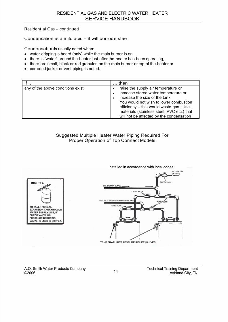
Suggested Multiple Heater Water Piping Required ForProper Operation of Top Connect Models
TEMPERATURE/PRESSURE RELIEF VALVES
Installed in accordance with local codes.
A.O. Smith Water Products Company Technical Training Department©2006 Ashland City, TN14
8/18/2019 A.o. Smith Servicing Guide 320991-000
http://slidepdf.com/reader/full/ao-smith-servicing-guide-320991-000 16/72
RESIDENTIAL GAS AND ELECTRIC WATER HEATER
SERVICE HANDBOOK
Residential Gas – cont inued
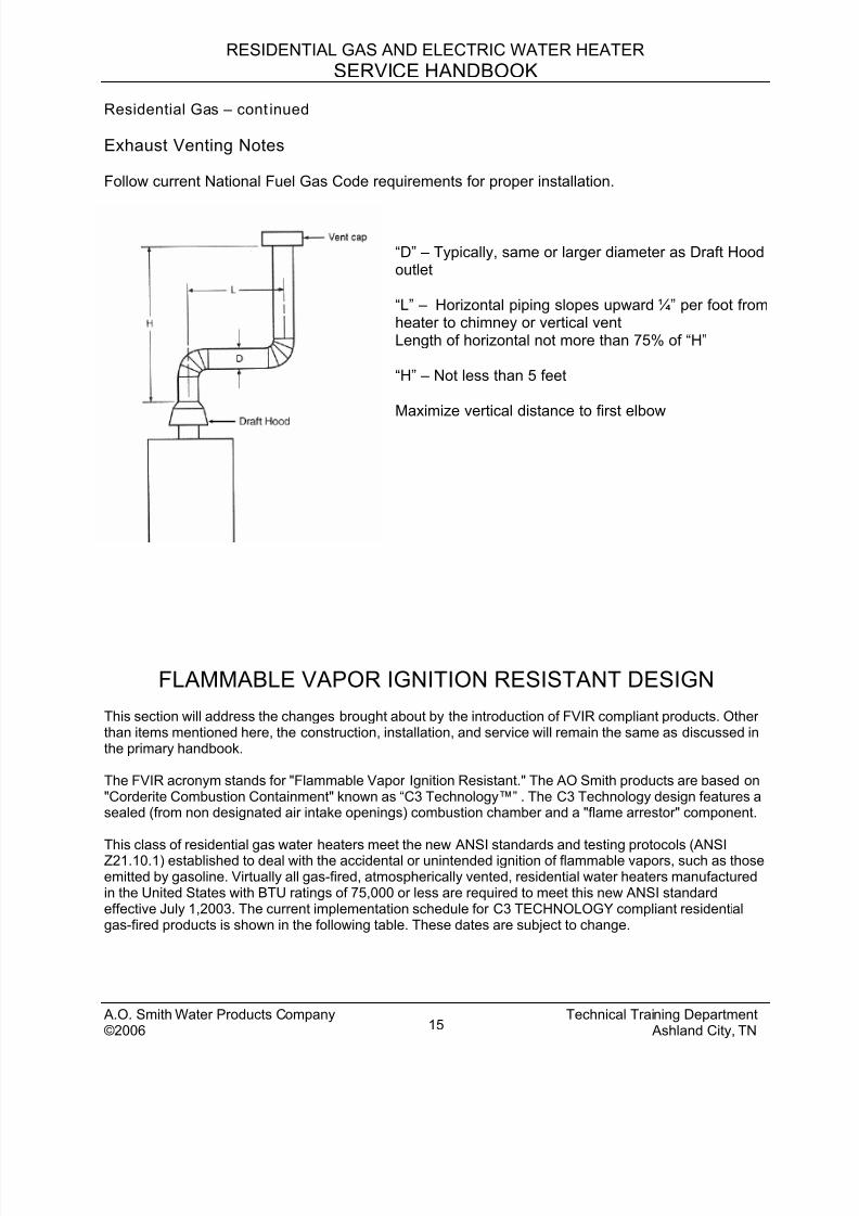
Exhaust Venting Notes
Follow current National Fuel Gas Code requirements for proper installation.
“D” – Typically, same or larger diameter as Draft Hoodoutlet
“L” – Horizontal piping slopes upward ¼” per foot fromheater to chimney or vertical ventLength of horizontal not more than 75% of “H”
“H” – Not less than 5 feet
Maximize vertical distance to first elbow
FLAMMABLE VAPOR IGNITION RESISTANT DESIGN
This section will address the changes brought about by the introduction of FVIR compliant products. Otherthan items mentioned here, the construction, installation, and service will remain the same as discussed inthe primary handbook.
The FVIR acronym stands for "Flammable Vapor Ignition Resistant." The AO Smith products are based on"Corderite Combustion Containment" known as “C3 Technology™” . The C3 Technology design features asealed (from non designated air intake openings) combustion chamber and a "flame arrestor" component.
This class of residential gas water heaters meet the new ANSI standards and testing protocols (ANSIZ21.10.1) established to deal with the accidental or unintended ignition of flammable vapors, such as thoseemitted by gasoline. Virtually all gas-fired, atmospherically vented, residential water heaters manufacturedin the United States with BTU ratings of 75,000 or less are required to meet this new ANSI standardeffective July 1,2003. The current implementation schedule for C3 TECHNOLOGY compliant residentialgas-fired products is shown in the following table. These dates are subject to change.
A.O. Smith Water Products Company Technical Training Department©2006 Ashland City, TN15
8/18/2019 A.o. Smith Servicing Guide 320991-000
http://slidepdf.com/reader/full/ao-smith-servicing-guide-320991-000 17/72
RESIDENTIAL GAS AND ELECTRIC WATER HEATER
SERVICE HANDBOOK
IMPLEMENTATIONCATEGORY
ANTICIPATEDINTRODUCTION
CLASS OF PRODUCTSINCLUDED IN THIS CATEGORY
Phase I July 1, 200330, 40, and 50 gallon atmospheric vented. (Manufactured housingmodels are excluded.)
Phase II January 1, 200530, 40, and 50 gallon power-vented models. (Manufactured housing
models are excluded.)Phase III July 1, 2005 All other gas-fired models with inputs of 75,000 BTU or less.
This supplement addresses the July1, 2003 compliant products.
In addition to the standard water heater design discussed in the main service handbook, the C3 Technologydesign also includes:
• A LDO (Lint Dust and Oil) screen over the combustion air intake
• A Flame Arrestor
• A combustion chamber Thermal Cut Off (TCO) limit
An additional tool for these products might be a vacuum cleaner with both blowing and vacuumingcapabilities. Also include the long, narrow crevasse accessory.
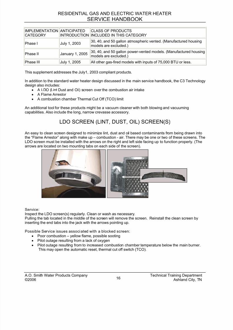
LDO SCREEN (LINT, DUST, OIL) SCREEN(S)
An easy to clean screen designed to minimize lint, dust and oil based contaminants from being drawn intothe “Flame Arrestor” along with make up – combustion - air. There may be one or two of these screens. TheLDO screen must be installed with the arrows on the right and left side facing up to function properly. (Thearrows are located on two mounting tabs on each side of the screen).
Service:Inspect the LDO screen(s) regularly. Clean or wash as necessary.Pulling the tab located in the middle of the screen will remove the screen. Reinstall the clean screen byinserting the end tabs into the jack with the arrows pointing up.
Possible Service issues associated with a blocked screen:• Poor combustion – yellow flame, possible sooting
• Pilot outage resulting from a lack of oxygen
• Pilot outage resulting from to increased combustion chamber temperature below the main burner.This may open the automatic reset, thermal cut off switch (TCO).
A.O. Smith Water Products Company Technical Training Department©2006 Ashland City, TN16
8/18/2019 A.o. Smith Servicing Guide 320991-000
http://slidepdf.com/reader/full/ao-smith-servicing-guide-320991-000 18/72
RESIDENTIAL GAS AND ELECTRIC WATER HEATER
SERVICE HANDBOOK
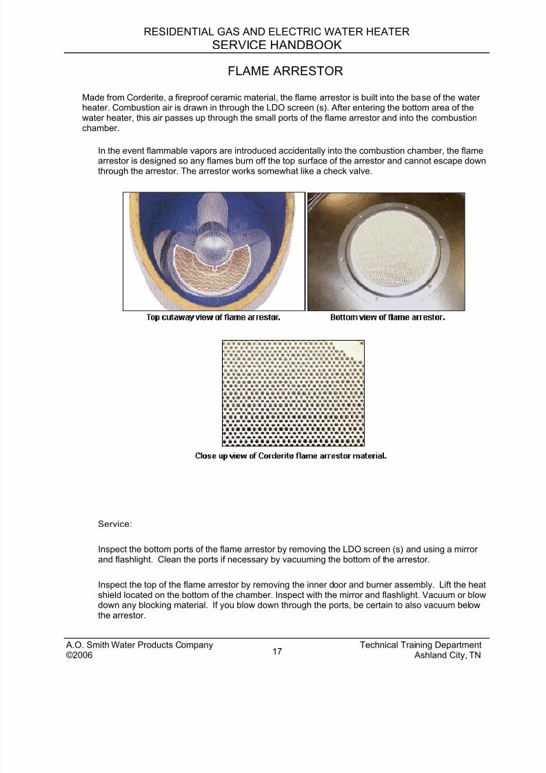
FLAME ARRESTOR
Made from Corderite, a fireproof ceramic material, the flame arrestor is built into the base of the waterheater. Combustion air is drawn in through the LDO screen (s). After entering the bottom area of thewater heater, this air passes up through the small ports of the flame arrestor and into the combustionchamber.
In the event flammable vapors are introduced accidentally into the combustion chamber, the flamearrestor is designed so any flames burn off the top surface of the arrestor and cannot escape downthrough the arrestor. The arrestor works somewhat like a check valve.
Service:
Inspect the bottom ports of the flame arrestor by removing the LDO screen (s) and using a mirrorand flashlight. Clean the ports if necessary by vacuuming the bottom of the arrestor.
Inspect the top of the flame arrestor by removing the inner door and burner assembly. Lift the heatshield located on the bottom of the chamber. Inspect with the mirror and flashlight. Vacuum or blowdown any blocking material. If you blow down through the ports, be certain to also vacuum belowthe arrestor.
A.O. Smith Water Products Company Technical Training Department©2006 Ashland City, TN17
8/18/2019 A.o. Smith Servicing Guide 320991-000
http://slidepdf.com/reader/full/ao-smith-servicing-guide-320991-000 19/72
RESIDENTIAL GAS AND ELECTRIC WATER HEATER
SERVICE HANDBOOK
If there has been a flammable vapor ignition, a qualified service agent needs to inspect the arrestorfor cracks. The arrestor is not a replaceable part – the heater would need to be replaced.
Possible service issues associated with the flame arrestor.
• Poor combustion – yellow flame, sooting, possible carbon monoxide production.
• Pilot outage due to lack of oxygen. Continued pilot outage or finding that the LDO screen(s) isheavily blocked would warrant inspection of the flame arrestor.
• Pilot outage due to increased combustion chamber temperatures below the main burner. This mayopen the automatic reset, thermal cut off switch (TCO).
• The flame arrestor having contained a flammable vapor ignition. The TCO will open and thechamber and arrestor should be inspected by a qualified service agent.
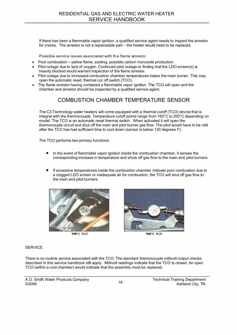
COMBUSTION CHAMBER TEMPERATURE SENSOR
The C3 Technology water heaters will come equipped with a thermal cutoff (TCO) device that is
integral with the thermocouple. Temperature cutoff points range from 160°C to 200°C depending onmodel. The TCO is an automatic reset thermal switch. When activated it will open thethermocouple circuit and shut off the main and pilot burner gas flow. The pilot would have to be relitafter the TCO has had sufficient time to cool down (sensor is below 120 degrees F).
The TCO performs two primary functions:
• In the event of flammable vapor ignition inside the combustion chamber, it senses thecorresponding increase in temperature and shuts off gas flow to the main and pilot burners.
• If excessive temperatures inside the combustion chamber indicate poor combustion due to
a clogged LDO screen or inadequate air for combustion, the TCO will shut off gas flow tothe main and pilot burners.
SERVICE:
There is no routine service associated with the TCO. The standard thermocouple millivolt output checksdescribed in this service handbook still apply. Millivolt readings indicate that the TCO is closed. An openTCO (within a cool chamber) would indicate that the assembly must be replaced.
A.O. Smith Water Products Company Technical Training Department©2006 Ashland City, TN18

8/18/2019 A.o. Smith Servicing Guide 320991-000
http://slidepdf.com/reader/full/ao-smith-servicing-guide-320991-000 20/72
RESIDENTIAL GAS AND ELECTRIC WATER HEATER
SERVICE HANDBOOK
The TCO is an integral part of the thermocouple and not replaceable as a separate item. A pilot burnerassembly must be reinstalled. On repeated calls of no hot water or pilot outage, a clogged/dirty LDO screenmight be the cause and should be checked. Keep in mind this TCO will shut off the pilot and main burnerwhen activated.
With the different cutoff temperature set-points of TCO devices for different model water heaters, it isimportant that the correct part is used when replacement of the pilot burner assembly is necessary.
Possible service issues associated with the Thermal Cut Off switch being opened:
• Pilot outage due to increased combustion chamber temperatures below the main burner. This mayopen the automatic reset, thermal cut off switch (TCO).
• The flame arrestor having contained a flammable vapor ignition. The TCO will open and thechamber and arrestor should be inspected by a qualified service agent.
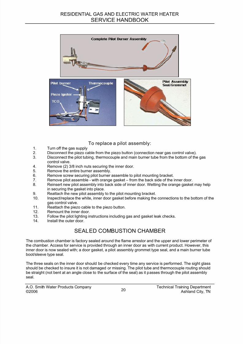
ONE PIECE PILOT BURNER ASSEMBLY
C3 Technology models feature a "one piece" pilot burner assembly. This assembly will be coveredunder a minimum 6 year parts warranty on all C3 Technology models, 10 years on premium models.
There are five main components that make up this pilot assembly:
1. Thermocouple with integral Thermal Cut Off switch (TCO).
2. Pilot burner w/orifice and tubing
3. Piezo igniter cable
4. Pilot assembly seal/grommet (orange).
5. An inner door gasket (white) will also be included.
A.O. Smith Water Products Company Technical Training Department©2006 Ashland City, TN19
8/18/2019 A.o. Smith Servicing Guide 320991-000
http://slidepdf.com/reader/full/ao-smith-servicing-guide-320991-000 21/72
RESIDENTIAL GAS AND ELECTRIC WATER HEATER
SERVICE HANDBOOK
To replace a pilot assembly:1. Turn off the gas supply2. Disconnect the piezo cable from the piezo button (connection near gas control valve).3. Disconnect the pilot tubing, thermocouple and main burner tube from the bottom of the gas
control valve.4. Remove (2) 3/8 inch nuts securing the inner door.5. Remove the entire burner assembly.6. Remove screw securing pilot burner assemble to pilot mounting bracket.
7. Remove pilot assemble - with orange gasket – from the back side of the inner door.8. Reinsert new pilot assembly into back side of inner door. Wetting the orange gasket may help
in securing the gasket into place.9. Reattach the new pilot assembly to the pilot mounting bracket.10. Inspect/replace the white, inner door gasket before making the connections to the bottom of the
gas control valve.11. Reattach the piezo cable to the piezo button.12. Remount the inner door.13. Follow the pilot lighting instructions including gas and gasket leak checks.14. Install the outer door.
SEALED COMBUSTION CHAMBER
The combustion chamber is factory sealed around the flame arrestor and the upper and lower perimeter ofthe chamber. Access for service is provided through an inner door as with current product. However, thisinner door is now sealed with; a door gasket, a pilot assembly grommet type seal, and a main burner tubeboot/sleeve type seal.
The three seals on the inner door should be checked every time any service is performed. The sight glassshould be checked to insure it is not damaged or missing. The pilot tube and thermocouple routing shouldbe straight (not bent at an angle close to the surface of the seal) as it passes through the pilot assemblyseal.
A.O. Smith Water Products Company Technical Training Department©2006 Ashland City, TN20
8/18/2019 A.o. Smith Servicing Guide 320991-000
http://slidepdf.com/reader/full/ao-smith-servicing-guide-320991-000 22/72
RESIDENTIAL GAS AND ELECTRIC WATER HEATER
SERVICE HANDBOOK
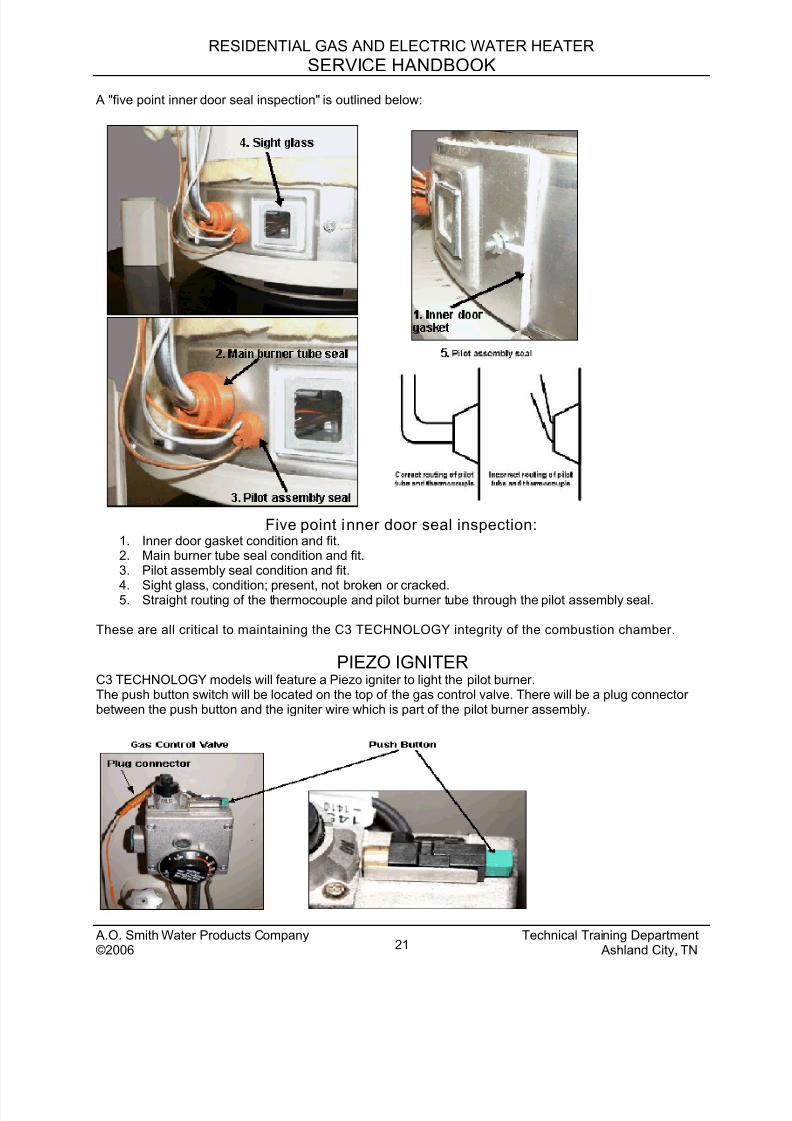
A "five point inner door seal inspection" is outlined below:
Five point inner door seal inspection:1. Inner door gasket condition and fit.2. Main burner tube seal condition and fit.3. Pilot assembly seal condition and fit.
4. Sight glass, condition; present, not broken or cracked.5. Straight routing of the thermocouple and pilot burner tube through the pilot assembly seal.
These are all critical to maintaining the C3 TECHNOLOGY integrity of the combustion chamber.
PIEZO IGNITERC3 TECHNOLOGY models will feature a Piezo igniter to light the pilot burner.The push button switch will be located on the top of the gas control valve. There will be a plug connectorbetween the push button and the igniter wire which is part of the pilot burner assembly.
A.O. Smith Water Products Company Technical Training Department©2006 Ashland City, TN21
8/18/2019 A.o. Smith Servicing Guide 320991-000
http://slidepdf.com/reader/full/ao-smith-servicing-guide-320991-000 23/72
RESIDENTIAL GAS AND ELECTRIC WATER HEATER
SERVICE HANDBOOK
FLAMMABLE VAPOR IGNITION RESISTANTWATER HEATER SERVICE TIP:
TO KEEP YOUR WATER HEATER IN PEAK PERFORMANCE
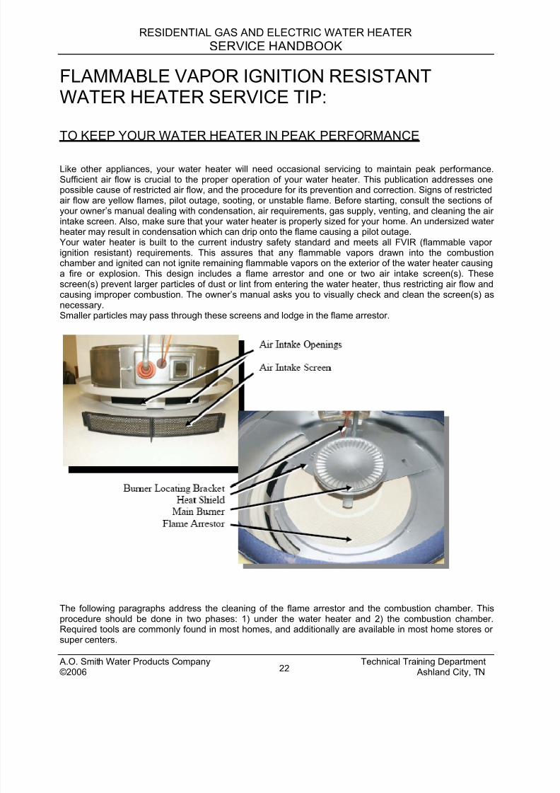
Like other appliances, your water heater will need occasional servicing to maintain peak performance.Sufficient air flow is crucial to the proper operation of your water heater. This publication addresses onepossible cause of restricted air flow, and the procedure for its prevention and correction. Signs of restrictedair flow are yellow flames, pilot outage, sooting, or unstable flame. Before starting, consult the sections ofyour owner’s manual dealing with condensation, air requirements, gas supply, venting, and cleaning the airintake screen. Also, make sure that your water heater is properly sized for your home. An undersized waterheater may result in condensation which can drip onto the flame causing a pilot outage.Your water heater is built to the current industry safety standard and meets all FVIR (flammable vaporignition resistant) requirements. This assures that any flammable vapors drawn into the combustionchamber and ignited can not ignite remaining flammable vapors on the exterior of the water heater causing
a fire or explosion. This design includes a flame arrestor and one or two air intake screen(s). Thesescreen(s) prevent larger particles of dust or lint from entering the water heater, thus restricting air flow andcausing improper combustion. The owner’s manual asks you to visually check and clean the screen(s) asnecessary.Smaller particles may pass through these screens and lodge in the flame arrestor.
The following paragraphs address the cleaning of the flame arrestor and the combustion chamber. Thisprocedure should be done in two phases: 1) under the water heater and 2) the combustion chamber.Required tools are commonly found in most homes, and additionally are available in most home stores orsuper centers.
A.O. Smith Water Products Company Technical Training Department©2006 Ashland City, TN22
8/18/2019 A.o. Smith Servicing Guide 320991-000
http://slidepdf.com/reader/full/ao-smith-servicing-guide-320991-000 24/72
RESIDENTIAL GAS AND ELECTRIC WATER HEATER
SERVICE HANDBOOK
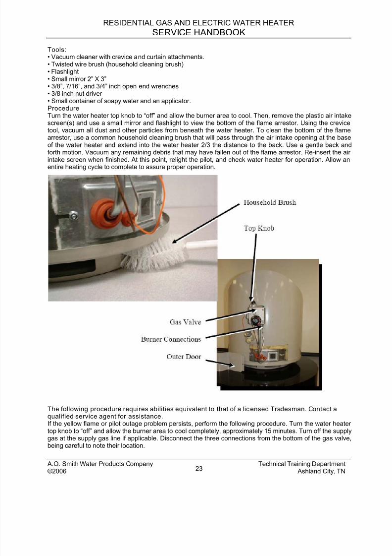
Tools:• Vacuum cleaner with crevice and curtain attachments.• Twisted wire brush (household cleaning brush)• Flashlight• Small mirror 2” X 3”• 3/8”, 7/16”, and 3/4” inch open end wrenches• 3/8 inch nut driver• Small container of soapy water and an applicator.ProcedureTurn the water heater top knob to “off” and allow the burner area to cool. Then, remove the plastic air intakescreen(s) and use a small mirror and flashlight to view the bottom of the flame arrestor. Using the crevicetool, vacuum all dust and other particles from beneath the water heater. To clean the bottom of the flamearrestor, use a common household cleaning brush that will pass through the air intake opening at the baseof the water heater and extend into the water heater 2/3 the distance to the back. Use a gentle back andforth motion. Vacuum any remaining debris that may have fallen out of the flame arrestor. Re-insert the airintake screen when finished. At this point, relight the pilot, and check water heater for operation. Allow anentire heating cycle to complete to assure proper operation.
The following procedure requires abilities equivalent to that of a licensed Tradesman. Contact aqualified service agent for assistance.If the yellow flame or pilot outage problem persists, perform the following procedure. Turn the water heatertop knob to “off” and allow the burner area to cool completely, approximately 15 minutes. Turn off the supplygas at the supply gas line if applicable. Disconnect the three connections from the bottom of the gas valve,being careful to note their location.
Technical Training Department A.O. Smith Water Products Company©2006 Ashland City, TN23
8/18/2019 A.o. Smith Servicing Guide 320991-000
http://slidepdf.com/reader/full/ao-smith-servicing-guide-320991-000 25/72
RESIDENTIAL GAS AND ELECTRIC WATER HEATER
SERVICE HANDBOOK
A.O. Smith Water Products Company Technical Training Department©2006 Ashland City, TN24
WARNINGDo not bend the gas valve connections too far; doing so may result in damage.Remove the outer door from around the burner tubing at the base of the water heater. Remove the Piezoigniter (with the orange wire) from the gas valve by sliding it back toward the tank (leave the orange wire inthe inner door assembly).Remove the 3/8” nuts, holding the inner door and white gasket in place. Place some protection such asnewspaper to protect the floor from debris. Carefully remove the burner from the combustion chamber.There may be soot or other materials collected on the top of the main burner; try not to dump any debris offof the burner until it and the inner door have been removed from the water heater.TAKE CARE NOT TO DAMAGE THE WHITE GASKET ON THE INSIDE OF THE INNER DOOR.
Inspect the radiation shield (thin circular metal sheet under the burner and above the flame arrestor). If anyof the sides of the radiation shield are touching the base (disrupting air flow), small feet can be obtainedfree of charge by contacting our call center at 800-527-1953 and requesting them.Vacuum the main assembly and pilot burner assembly. Vacuum the top of the radiation shield locatedinside the burner chamber. Use the vacuum drapery brush attachment to clean the inside of the combustionchamber and the exposed area of the flame arrestor. Use the crevice tool to vacuum under the radiationshield as much as possible without bending the shield upward more than one inch or so.
Re-insert the burner taking care that the main burner tube is seated in the burner positioning bracket.
Carefully reposition the inner door w/gasket over the bolts on the combustion chamber. Do not tighten thenuts down until the main burner, pilot burner, and thermocouple are attached and tightened. Make sure thatthe white fibrous door gasket is not folded over and protrudes out from the inner door in all directions. Thentighten the 3/8” nuts to hold the inner door in place.Check the gas connections for proper fitting and then light the pilot, following the directions on the side ofthe water heater. Once the pilot is lit, turn the valve to the “ON” position and ignite the main flame. Brushsoapy water on the gas connections and look for bubbling. This is an indication of a gas leak. If bubblesappear, shut off gas supply and check fittings. Re-light the pilot and check for leaks again, repeating thesoapy water solution method.
Important Service Reminder Any time service is performed on C3 TECHNOLOGY product the Five Point Inner Door Seal Inspectionoutlined in the Sealed Combustion Chamber section should be performed and the LDO Screen (s) shouldbe inspected for proper installation (arrows up) and cleaned before leaving.
Other features All C3 TECHNOLOGY models will feature Green Choice by having a low NOx (nitrous oxide) burner whichmeets SCAQMD rule 1121. All C3 TECHNOLOGY models will have a brass drain valve standard.
8/18/2019 A.o. Smith Servicing Guide 320991-000
http://slidepdf.com/reader/full/ao-smith-servicing-guide-320991-000 26/72
RESIDENTIAL GAS AND ELECTRIC WATER HEATER
SERVICE HANDBOOK
See the “ Technical Bulletins Section” of this manual for explanations of:Water HammerMineral Buildup Aluminum HydroxideCondensation
Discolored WaterSmelly WaterChlorination ProcessLack of hot waterThermal ExpansionTemperature and Pressure Relief Valve Operation
Parts Replacement – The parts on these models may change due to improvements/changes inthe products. To order the current, correct replacement part for your model gas water heater, youmust know the model number and (complete) serial number of your water heater. Thisinformation will be located on a black and white label, on the front of your water heater – this labelwill also display a star within a circle (the CSA symbol). A sample might be:Model “PCVG-50 – 250” “Ser No. MB03-(numbers) – 250”.
To order parts, contact your local A.O. Smith Contractor or Distributor, phone AOSparts at 800-433-2545 or contact A. O. Smith on Web site:
“www.aosmithwaterheaters.com”
A.O. Smith Water Products Company Technical Training Department©2006 Ashland City, TN25
8/18/2019 A.o. Smith Servicing Guide 320991-000
http://slidepdf.com/reader/full/ao-smith-servicing-guide-320991-000 27/72
RESIDENTIAL GAS AND ELECTRIC WATER HEATER
SERVICE HANDBOOK
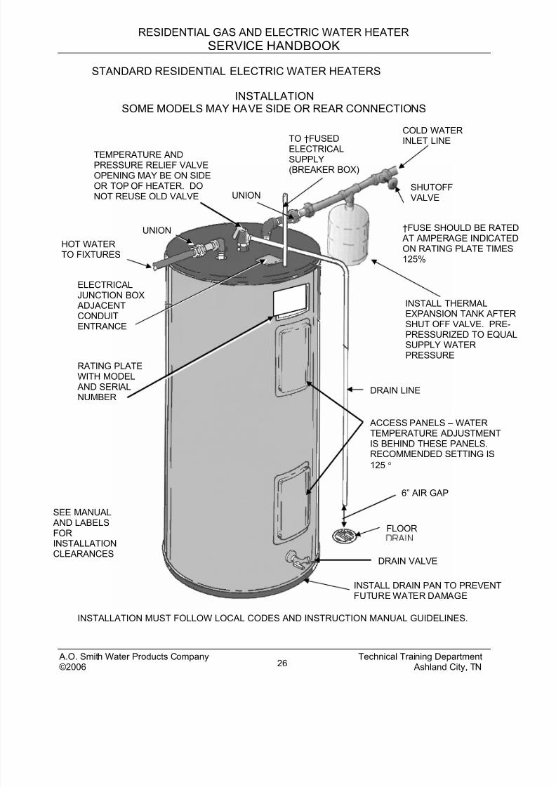
STANDARD RESIDENTIAL ELECTRIC WATER HEATERS
INSTALLATIONSOME MODELS MAY HAVE SIDE OR REAR CONNECTIONS
INSTALL DRAIN PAN TO PREVENTFUTURE WATER DAMAGE
DRAIN VALVE
UNION
FLOOR
6” AIR GAP
†FUSE SHOULD BE RATED AT AMPERAGE INDICATEDON RATING PLATE TIMES125%
SEE MANUAL AND LABELSFORINSTALLATION
CLEARANCES
ACCESS PANELS – WATERTEMPERATURE ADJUSTMENTIS BEHIND THESE PANELS.RECOMMENDED SETTING IS
125 °
ELECTRICALJUNCTION BOX ADJACENTCONDUITENTRANCE
RATING PLATEWITH MODEL AND SERIALNUMBER
HOT WATERTO FIXTURES
DRAIN LINE
INSTALL THERMALEXPANSION TANK AFTERSHUT OFF VALVE. PRE-PRESSURIZED TO EQUALSUPPLY WATERPRESSURE
SHUTOFFVALVE
TO †FUSEDELECTRICALSUPPLY(BREAKER BOX)
TEMPERATURE ANDPRESSURE RELIEF VALVEOPENING MAY BE ON SIDEOR TOP OF HEATER. DONOT REUSE OLD VALVE UNION
COLD WATER
INLET LINE
INSTALLATION MUST FOLLOW LOCAL CODES AND INSTRUCTION MANUAL GUIDELINES.
A.O. Smith Water Products Company Technical Training Department©2006 Ashland City, TN26

8/18/2019 A.o. Smith Servicing Guide 320991-000
http://slidepdf.com/reader/full/ao-smith-servicing-guide-320991-000 28/72
RESIDENTIAL GAS AND ELECTRIC WATER HEATER
SERVICE HANDBOOK
STANDARD RESIDENTIAL ELECTRIC WATER HEATERS
This portion of this manual applies to the Operation and Servicing of Residential Electric,Tank Type, Water Heaters. The illustrations are for two element models but the
information also applies to single element models.
TEMPERATURE/PRESSURE RELIEF VALVES
Multiple Heater Water PipingRequired for Proper Operation
of Top Connect Models
A.O. Smith Water Products Company Technical Training Department©2006 Ashland City, TN27
8/18/2019 A.o. Smith Servicing Guide 320991-000
http://slidepdf.com/reader/full/ao-smith-servicing-guide-320991-000 29/72
RESIDENTIAL GAS AND ELECTRIC WATER HEATER
SERVICE HANDBOOK
STANDARD RESIDENTIAL ELECTRIC WATER HEATER SERVICE GUIDELINES
Construction
See “General Section” for features common to both gas and electric models.
Miscellaneous:
Amperage (Amps) (1 phase) = Watts divided by Volts
Amperage (3 phase) = (Watts X .577) divided by Volts
KW Required = (GPH X 8.25 X Temp. Rise X 1.0) divided by (3413)
Ohms = Volts divided by Amperes
One kilowatt is equal to 1000 watts
One kilowatt is equal to 3,413 BTU
Recovery Rate = (KW X 3413) divided by (Temp. Rise X 8.25)
Rise (F ) = (KW X 3413) divided by (GPH X 8.25)
Supply electrical fusing or breakers should be sized at least 125% of expected heateramperage.
Water weighs 8.25 pounds per gallon at 120 °F (49°C).
% of Hot water = (Mixed temp. – Cold) divided by (Hot temp. – Cold)
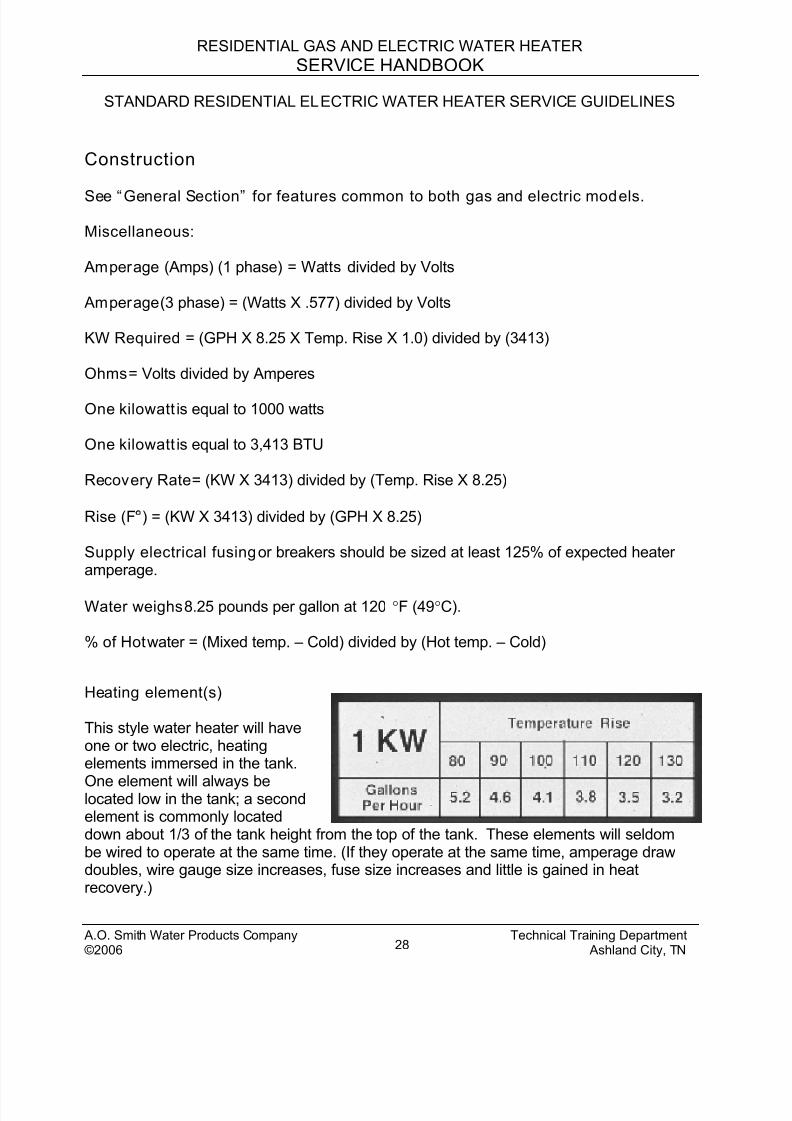
Heating element(s)
This style water heater will haveone or two electric, heatingelements immersed in the tank.
One element will always belocated low in the tank; a secondelement is commonly locateddown about 1/3 of the tank height from the top of the tank. These elements will seldombe wired to operate at the same time. (If they operate at the same time, amperage drawdoubles, wire gauge size increases, fuse size increases and little is gained in heatrecovery.)
A.O. Smith Water Products Company Technical Training Department©2006 Ashland City, TN28
8/18/2019 A.o. Smith Servicing Guide 320991-000
http://slidepdf.com/reader/full/ao-smith-servicing-guide-320991-000 30/72
RESIDENTIAL GAS AND ELECTRIC WATER HEATER
SERVICE HANDBOOK
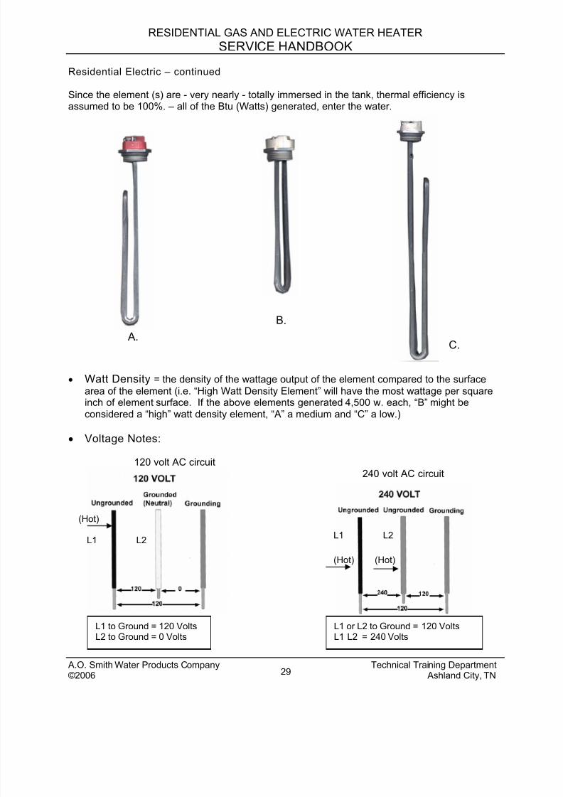
Residential Electric – continued
Since the element (s) are - very nearly - totally immersed in the tank, thermal efficiency isassumed to be 100%. – all of the Btu (Watts) generated, enter the water.
B.
A.C.
• Watt Density = the density of the wattage output of the element compared to the surface
area of the element (i.e. “High Watt Density Element” will have the most wattage per squareinch of element surface. If the above elements generated 4,500 w. each, “B” might be
considered a “high” watt density element, “A” a medium and “C” a low.)
• Voltage Notes:
120 volt AC circuit240 volt AC circuit
(Hot)
L1 L2
(Hot)(Hot)
L1 L2
L1 to Ground = 120 VoltsL2 to Ground = 0 Volts
L1 or L2 to Ground = 120 VoltsL1 L2 = 240 Volts
A.O. Smith Water Products Company Technical Training Department©2006 Ashland City, TN29
8/18/2019 A.o. Smith Servicing Guide 320991-000
http://slidepdf.com/reader/full/ao-smith-servicing-guide-320991-000 31/72
RESIDENTIAL GAS AND ELECTRIC WATER HEATER
SERVICE HANDBOOK
Residential Electric – continued
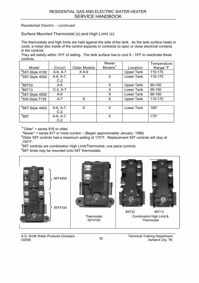
Surface Mounted Thermostat (s) and High Limit (s)
The thermostats and high limits are held against the side of the tank. As the tank surface heats orcools, a metal disc inside of the control expands or contracts to open or close electrical contacts
in the controls.They will satisfy within 10°F of setting. The tank surface has to cool 8 - 15°F to reactivate thesecontrols.
Model Circui t Older Models
Newer
Models1
LocationTemperature
Range °F259T-Style 4100 A-6, A-7 X A-6 Upper Tank 110-170
259T-Style 4000 A-6, A-7,
C-2X X Lower Tank 110-170
389T33 A-6 X Upper Tank 90-150
389T13 C-2, A-7 X Lower Tank 90-150
259T-Style 4000 A-6 X Lower Tank 90-150
2
AW-Style 7135 A-7 X X Upper Tank 110-170
466T-Style 4400 A-6, A-7,
C-2X X Lower Tank 190°
389T A-6, A-7,
C-2X 170°
1”Older” = series 916 or older.
“Newer” = series 917 or more current – (Began approximately January, 1996)2Older 59T controls had a maximum setting of 170°F. Replacement 59T controls will stop at
150°F.389T controls are combination High Limit/Thermostat, one piece controls.
466T limits may be mounted onto 59T thermostats.
89T33 89T13
Thermostat59T4100
66T4400
Combination High Limit &Thermostat
59T4100
A.O. Smith Water Products Company Technical Training Department©2006 Ashland City, TN30
8/18/2019 A.o. Smith Servicing Guide 320991-000
http://slidepdf.com/reader/full/ao-smith-servicing-guide-320991-000 32/72
RESIDENTIAL GAS AND ELECTRIC WATER HEATER
SERVICE HANDBOOK
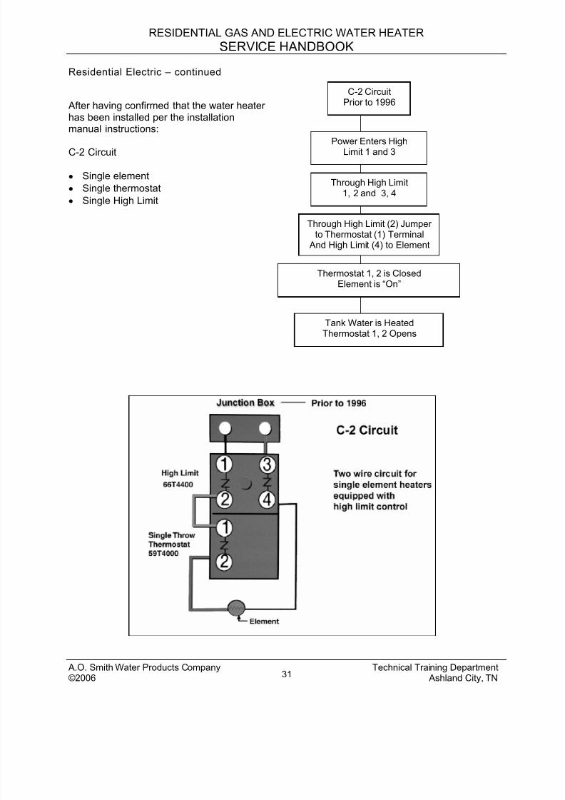
Residential Electric – continued
Power Enters HighLimit 1 and 3
Through High Limit1, 2 and 3, 4
Through High Limit (2) Jumperto Thermostat (1) Terminal
And High Limit (4) to Element
Thermostat 1, 2 is ClosedElement is “On”
Tank Water is HeatedThermostat 1, 2 Opens
C-2 CircuitPrior to 1996 After having confirmed that the water heater
has been installed per the installationmanual instructions:
C-2 Circuit
• Single element
• Single thermostat
• Single High Limit
A.O. Smith Water Products Company Technical Training Department©2006 Ashland City, TN31
8/18/2019 A.o. Smith Servicing Guide 320991-000
http://slidepdf.com/reader/full/ao-smith-servicing-guide-320991-000 33/72
RESIDENTIAL GAS AND ELECTRIC WATER HEATER
SERVICE HANDBOOK
Residential Electric – continued
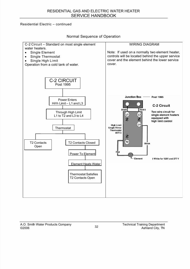
Normal Sequence of Operation
C-2 Circui t – Standard on most single element
water heaters.
• Single Element
• Single Thermostat
• Single High LimitOperation from a cold tank of water.
WIRING DIAGRAM
Note: If used on a normally two element heatecontrols will be located behind the upper serviccover and the element behind the lower servicecover.
Thermostat SatisfiesT2 Contacts Open
Power EntersHi h Limit – L1 and L3
Through High LimitL1 to T2 and L3 to L4
Thermostat
T2 ContactsOpen
Power To Element
Element Heats Water
T2 Contacts Closed
Post 19952 CIRCUITC-
A.O. Smith Water Products Company Technical Training Department© Ashland City, TN2006 32
8/18/2019 A.o. Smith Servicing Guide 320991-000
http://slidepdf.com/reader/full/ao-smith-servicing-guide-320991-000 34/72
RESIDENTIAL GAS AND ELECTRIC WATER HEATER
SERVICE HANDBOOK
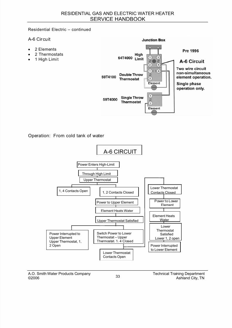
Residential Electric – continued
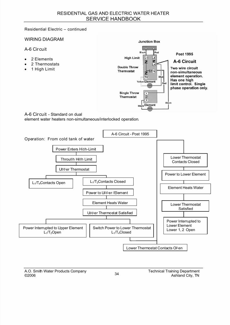
A-6 Circuit
• 2 Elements
• 2 Thermostats
• 1 High Limi t
Operation: From cold tank of water
6 CIRCUIT A-
r
Power Interrupted toUpper ElementUpper Thermostat, 1,2 Open
Switch Power to LowerThermostat – UpperThermostat 1 4 Closed
Lower ThermostatContacts Open
Through High Limit
Upper Thermostat
Lower Thermostat
Contacts Closed 1, 4 Contacts Open 1, 2 Contacts Closed
Power to Upper Element
Element Heats Water
Upper Thermostat Satisfied
Power Interrupted to Lower Element
Lower
Thermostat Satisfied
Lower 1, 2 open
Element Heats Water
Power to Lo ewElement
Power Enters High-Limit
A.O. Smith Water Products Company Technical Training Department©2006 Ashland City, TN33
8/18/2019 A.o. Smith Servicing Guide 320991-000
http://slidepdf.com/reader/full/ao-smith-servicing-guide-320991-000 35/72
RESIDENTIAL GAS AND ELECTRIC WATER HEATER
SERVICE HANDBOOK
Residential Electric – continued
WIRING DIAGRAM
A-6 Circuit
• 2 Elements
• 2 Thermostats
• 1 High Limit
A-6 Circuit - Standard on dualelement water heaters non-simultaneous/interlocked operation.
A-6 Circuit - Post 1995
Operation: From cold tank of water
Power Enters Hi h-Limit
Throu h Hi h Limit
U er Thermostat
L1/T4 Contacts Open L1/T2 Contacts Closed
Power to U er /Element
Element Heats Water
U er Thermostat Satisfied
Power Interrupted to Upper ElementL1/T2 Open
Lower ThermostatContacts Closed
Power to Lower Element
Element Heats Water
Power Interrupted toLower ElementLower 1, 2 Open
Lower ThermostatSatisfied
Switch Power to Lower ThermostatL1/T4 Closed
Lower Thermostat Contacts O en
A.O. Smith Water Products Company Technical Training Department©2006 Ashland City, TN34
8/18/2019 A.o. Smith Servicing Guide 320991-000
http://slidepdf.com/reader/full/ao-smith-servicing-guide-320991-000 36/72
RESIDENTIAL GAS AND ELECTRIC WATER HEATER
SERVICE HANDBOOK
Residential Electric – continued
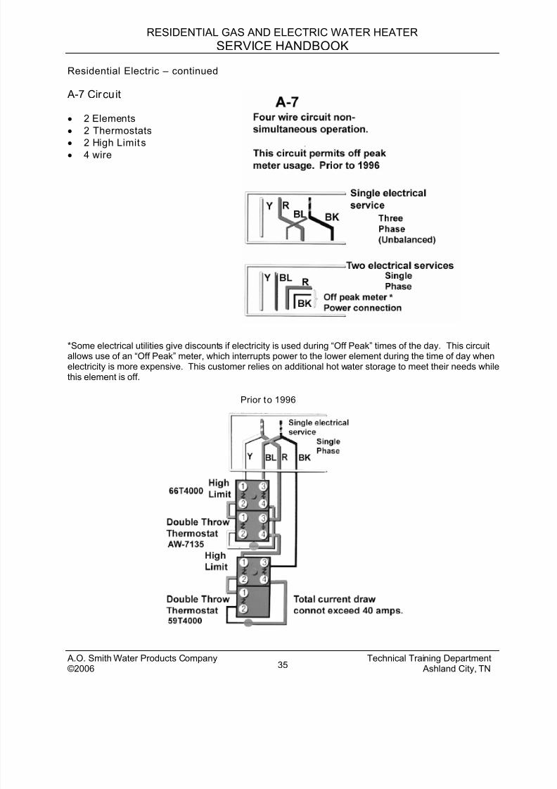
A-7 Circuit
• 2 Elements
• 2 Thermostats
• 2 High Limits
• 4 wire
*Some electrical utilities give discounts if electricity is used during “Off Peak” times of the day. This circuitallows use of an “Off Peak” meter, which interrupts power to the lower element during the time of day whenelectricity is more expensive. This customer relies on additional hot water storage to meet their needs whilethis element is off.
Prior to 1996
A.O. Smith Water Products Company Technical Training Department©2006 Ashland City, TN35
8/18/2019 A.o. Smith Servicing Guide 320991-000
http://slidepdf.com/reader/full/ao-smith-servicing-guide-320991-000 37/72
RESIDENTIAL GAS AND ELECTRIC WATER HEATER
SERVICE HANDBOOK
Residential Electric – continued
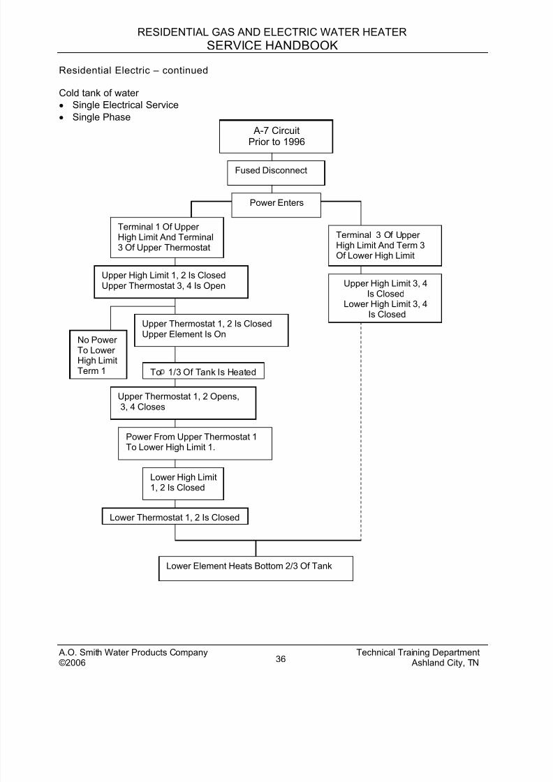
Cold tank of water
• Single Electrical Service
• Single Phase
Power Enters
Terminal 1 Of UpperHigh Limit And Terminal3 Of Upper Thermostat
Upper High Limit 1, 2 Is ClosedUpper Thermostat 3, 4 Is Open
Upper Thermostat 1, 2 Is ClosedUpper Element Is On
No PowerTo LowerHigh LimitTerm 1 To 1/3 Of Tank Is Heated
Upper Thermostat 1, 2 Opens,
3, 4 Closes
Power From Upper Thermostat 1To Lower High Limit 1.
Lower High Limit1, 2 Is Closed
Lower Thermostat 1, 2 Is Closed
Lower Element Heats Bottom 2/3 Of Tank
Upper High Limit 3, 4Is Closed
Lower High Limit 3, 4Is Closed
Terminal 3 Of UpperHigh Limit And Term 3Of Lower High Limit
Fused Disconnect
A-7 CircuitPrior to 1996
A.O. Smith Water Products Company Technical Training Department©2006 Ashland City, TN36
8/18/2019 A.o. Smith Servicing Guide 320991-000
http://slidepdf.com/reader/full/ao-smith-servicing-guide-320991-000 38/72
RESIDENTIAL GAS AND ELECTRIC WATER HEATER
SERVICE HANDBOOK
Residential Electric – continued
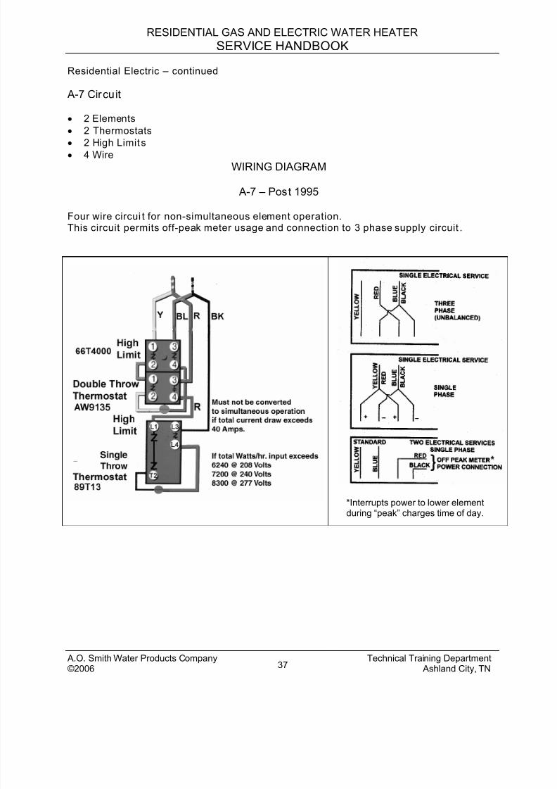
A-7 Circuit
• 2 Elements
• 2 Thermostats
• 2 High Limits
• 4 Wire
WIRING DIAGRAM
A-7 – Post 1995
Four wire circui t for non-simultaneous element operation.This circuit permits off-peak meter usage and connection to 3 phase supply circuit .
*Interrupts power to lower elementduring “peak” charges time of day.
A.O. Smith Water Products Company Technical Training Department©2006 Ashland City, TN37

8/18/2019 A.o. Smith Servicing Guide 320991-000
http://slidepdf.com/reader/full/ao-smith-servicing-guide-320991-000 39/72
RESIDENTIAL GAS AND ELECTRIC WATER HEATER
SERVICE HANDBOOK
Residential Electric – continued
Cold tank of water
• Single Electrical Service
• Single Phase
Fused Disconnect
Power to Upper High Limit 1,and Upper Thermostat 3
Upper High Limit 1, 2 is Closed.Upper Thermostat 3, 4 is Open
Upper Thermostat 1, 2 is ClosedUpper Element is On
Top 1/3 of Tank is Heated
Upper Thermostat 1, 2 OpensUpper Thermostat 3, 4 Closes
Power Flows BetweenUpper Thermostat 4 andLower High Limit L1
Lower High Limit L1 andLower Thermostat T2 is Closed
Lower Element Heats Bottom 2/3 of Tank
Upper High Limit 3, 4 is ClosedLower High Limit L3, L4 is Closed
Power to Upper High Limit 3and Lower High Limit L3
No Powerto LowerHigh LimitTerminal 1
A-7 CircuitPost 1995
A.O. Smith Water Products Company Technical Training Department©2006 Ashland City, TN38
8/18/2019 A.o. Smith Servicing Guide 320991-000
http://slidepdf.com/reader/full/ao-smith-servicing-guide-320991-000 40/72
RESIDENTIAL GAS AND ELECTRIC WATER HEATER
SERVICE HANDBOOK
A.O. Smith Water Products Company Technical Training Department©2006 Ashland City, TN39
Residential Electric – continued
CERTIFICATION AND APPROVALS
UL – UL-174 applies to Residential Electric Water Heaters
The following paragraph describes the relationship between ASHRAE, NAECA and theDepartment of Energy’s ENERGY FACTOR as it relates to the residential electric product lime. All of the A.O. Smith residential electric water heaters meet this code.
The American Society of Heating, Refrigeration and Air Conditioning Engineer (ASHRAE)guidelines follow the National Appliance Energy Conservationist Act (NAECA). NAECA followsthe Department of Energy (DOE) test procedures of the 1990 code of federal regulation, title 10,part 430 (64) which establishes minimum Energy Factors (EF) for water heaters of 12 kilowattsor less and a storage capacity of at least 20, but not more than 120 gallons.
Formula (as of January 2004) -The minimum EF allowed = .97 - .00132 x V (volume of storage)Example (EES-52; 50 gal. x .00132 = .066 Then .97 - .066 = .904 minimum allowable energyfactor).
8/18/2019 A.o. Smith Servicing Guide 320991-000
http://slidepdf.com/reader/full/ao-smith-servicing-guide-320991-000 41/72
RESIDENTIAL GAS AND ELECTRIC WATER HEATER
SERVICE HANDBOOK
Residential Electric – continued
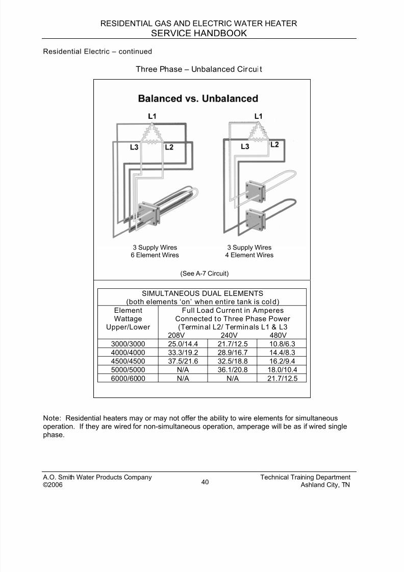
Three Phase – Unbalanced Circui t
SIMULTANEOUS DUAL ELEMENTS
(both elements ‘on’ when entire tank is cold)ElementWattage
Upper/Lower
Full Load Current in AmperesConnected to Three Phase Power(Terminal L2/ Terminals L1 & L3
208V 240V 480V
3000/3000 25.0/14.4 21.7/12.5 10.8/6.3
4000/4000 33.3/19.2 28.9/16.7 14.4/8.3
4500/4500 37.5/21.6 32.5/18.8 16.2/9.4
5000/5000 N/A 36.1/20.8 18.0/10.4
6000/6000 N/A N/A 21.7/12.5
(See A-7 Circuit)
3 Supply Wires4 Element Wires
3 Supply Wires6 Element Wires
Note: Residential heaters may or may not offer the ability to wire elements for simultaneousoperation. If they are wired for non-simultaneous operation, amperage will be as if wired singlephase.
A.O. Smith Water Products Company Technical Training Department©2006 Ashland City, TN40
8/18/2019 A.o. Smith Servicing Guide 320991-000
http://slidepdf.com/reader/full/ao-smith-servicing-guide-320991-000 42/72
RESIDENTIAL GAS AND ELECTRIC WATER HEATER
SERVICE HANDBOOK
Residential Electric – continued
SERVICE
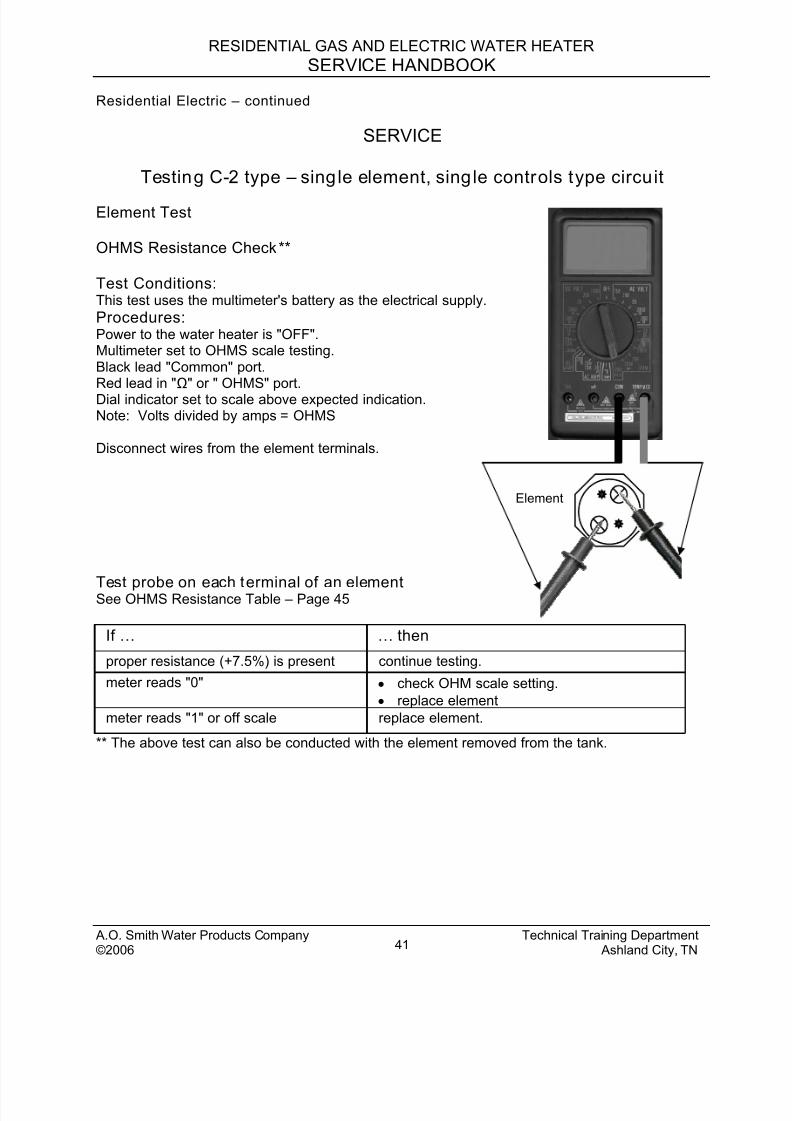
Testing C-2 type – single element, single controls type circuit
Element Test
OHMS Resistance Check**
Test Conditions:This test uses the multimeter's battery as the electrical supply.
Element
Procedures:Power to the water heater is "OFF".Multimeter set to OHMS scale testing.Black lead "Common" port.Red lead in "Ω" or " OHMS" port.Dial indicator set to scale above expected indication.Note: Volts divided by amps = OHMS
Disconnect wires from the element terminals.
Test probe on each terminal of an elementSee OHMS Resistance Table – Page 45
If … … then
proper resistance (+7.5%) is present continue testing.
meter reads "0" • check OHM scale setting.
• replace element
meter reads "1" or off scale replace element.
** The above test can also be conducted with the element removed from the tank.
A.O. Smith Water Products Company Technical Training Department©2006 Ashland City, TN41
8/18/2019 A.o. Smith Servicing Guide 320991-000
http://slidepdf.com/reader/full/ao-smith-servicing-guide-320991-000 43/72
RESIDENTIAL GAS AND ELECTRIC WATER HEATER
SERVICE HANDBOOK
Residential Electric – continued
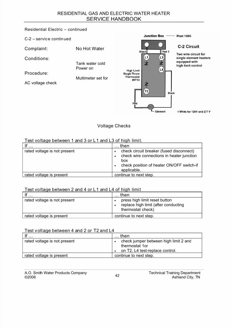
C-2 – service continued
Complaint: No Hot Water
Conditions:Tank water coldPower on
Procedure:Multimeter set for
AC voltage check
Voltage Checks
Test voltage between 1 and 3 or L1 and L3 of high limi t.
If … … thenrated voltage is not present • check circuit breaker (fused disconnect)
• check wire connections in heater junctionbox
• check position of heater ON/OFF switch-if
applicable.rated voltage is present continue to next step.
Test voltage between 2 and 4 or L1 and L4 of high limi t
If … … then
rated voltage is not present • press high limit reset button• replace high limit (after conducting
thermostat check)
rated voltage is present continue to next step.
Test voltage between 4 and 2 or T2 and L4If … … then
rated voltage is not present • check jumper between high limit 2 andthermostat 1or
• on T2, L4 test-replace control.
rated voltage is present continue to next step.
A.O. Smith Water Products Company Technical Training Department©2006 Ashland City, TN42
8/18/2019 A.o. Smith Servicing Guide 320991-000
http://slidepdf.com/reader/full/ao-smith-servicing-guide-320991-000 44/72
RESIDENTIAL GAS AND ELECTRIC WATER HEATER
SERVICE HANDBOOK
Residential Electric – continuedC-2 service “No Hot Water” – continued
Test between the two element terminals
If … … then
rated voltage is not present check wiring from control.rated voltage is present • repeat Ohms resistance test of element
• check for water leaks in piping or fixtures.
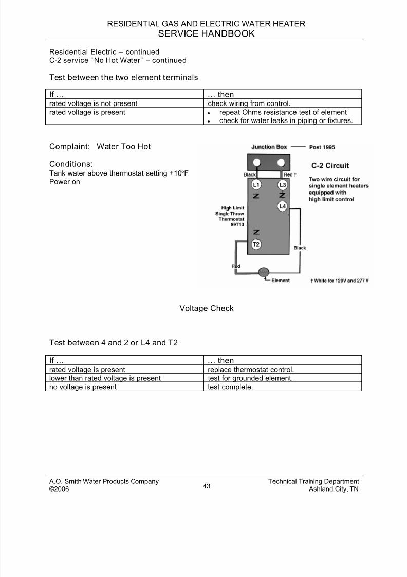
Complaint: Water Too Hot
Conditions:Tank water above thermostat setting +10°FPower on
Voltage Check
Test between 4 and 2 or L4 and T2
If … … then
rated voltage is present replace thermostat control.
lower than rated voltage is present test for grounded element.
no voltage is present test complete.
A.O. Smith Water Products Company Technical Training Department©2006 Ashland City, TN43
8/18/2019 A.o. Smith Servicing Guide 320991-000
http://slidepdf.com/reader/full/ao-smith-servicing-guide-320991-000 45/72
RESIDENTIAL GAS AND ELECTRIC WATER HEATER
SERVICE HANDBOOK
Residential Electric – continuedC-2 – service “Water Too Hot” – continued
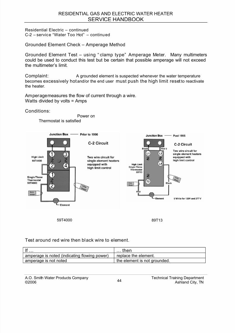
Grounded Element Check – Amperage Method
Grounded Element Test – using “ clamp type” Amperage Meter. Many multimeterscould be used to conduct this test but be certain that possible amperage will not exceedthe multimeter’s limit.
Complaint: A grounded element is suspected whenever the water temperature
becomes excessively hot and/or the end user must push the high limit reset to reactivate
the heater.
Amperage measures the flow of current through a wire.Watts divided by volts = Amps
Conditions:
Power onThermostat is satisfied
59T4000 89T13
Test around red wire then black wire to element.
If … … then
amperage is noted (indicating flowing power) replace the element.
amperage is not noted the element is not grounded.
A.O. Smith Water Products Company Technical Training Department©2006 Ashland City, TN44
8/18/2019 A.o. Smith Servicing Guide 320991-000
http://slidepdf.com/reader/full/ao-smith-servicing-guide-320991-000 46/72
RESIDENTIAL GAS AND ELECTRIC WATER HEATER
SERVICE HANDBOOK
Residential Electric – continued
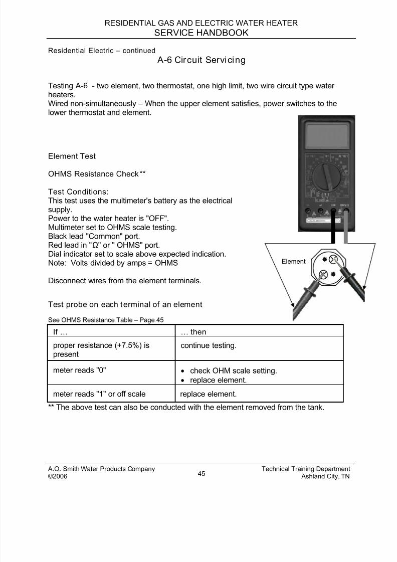
A-6 Circuit Servicing
Testing A-6 - two element, two thermostat, one high limit, two wire circuit type water
heaters.Wired non-simultaneously – When the upper element satisfies, power switches to thelower thermostat and element.
A.O. Smith Water Products Company Technical Training Department©2006 Ashland City, TN45
Element
Element Test
OHMS Resistance Check**
Test Conditions:This test uses the multimeter's battery as the electricalsupply.Power to the water heater is "OFF".Multimeter set to OHMS scale testing.Black lead "Common" port.Red lead in "Ω" or " OHMS" port.Dial indicator set to scale above expected indication.Note: Volts divided by amps = OHMS
Disconnect wires from the element terminals.
Test probe on each terminal of an element
See OHMS Resistance Table – Page 45
If … … then
proper resistance (+7.5%) ispresent
continue testing.
meter reads "0" • check OHM scale setting.
• replace element.
meter reads "1" or off scale replace element.
** The above test can also be conducted with the element removed from the tank.
8/18/2019 A.o. Smith Servicing Guide 320991-000
http://slidepdf.com/reader/full/ao-smith-servicing-guide-320991-000 47/72
RESIDENTIAL GAS AND ELECTRIC WATER HEATER
SERVICE HANDBOOK
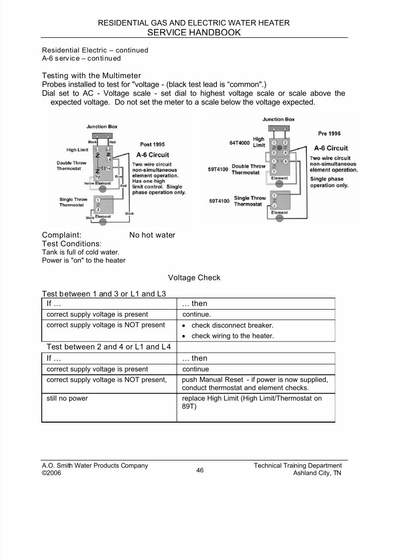
Residential Electric – continued A-6 serv ice – continued
Testing with the Multimeter Probes installed to test for "voltage - (black test lead is “common".)Dial set to AC - Voltage scale - set dial to highest voltage scale or scale above the
expected voltage. Do not set the meter to a scale below the voltage expected.
Complaint: No hot waterTest Conditions: Tank is full of cold water.Power is "on" to the heater
Voltage Check
Test between 1 and 3 or L1 and L3If … … then
correct supply voltage is present continue.
correct supply voltage is NOT present • check disconnect breaker.
• check wiring to the heater.
Test between 2 and 4 or L1 and L4
If … … then
correct supply voltage is present continue
correct supply voltage is NOT present, push Manual Reset - if power is now supplied,
conduct thermostat and element checks.still no power replace High Limit (High Limit/Thermostat on
89T)
A.O. Smith Water Products Company Technical Training Department©2006 Ashland City, TN46
8/18/2019 A.o. Smith Servicing Guide 320991-000
http://slidepdf.com/reader/full/ao-smith-servicing-guide-320991-000 48/72
RESIDENTIAL GAS AND ELECTRIC WATER HEATER
SERVICE HANDBOOK
A.O. Smith Water Products Company Technical Training Department©2006 Ashland City, TN47
Residential Electric – continued A-6 serv ice Vol tage Check “ No Hot Water ” – continued
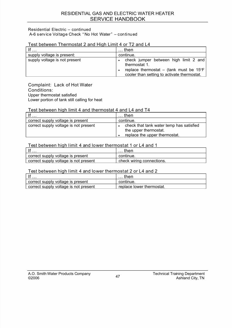
Test between Thermostat 2 and High Limit 4 or T2 and L4
If … … thensupply voltage is present: continue.
supply voltage is not present • check jumper between high limit 2 andthermostat 1.
• replace thermostat – (tank must be 15°Fcooler than setting to activate thermostat.
Complaint: Lack of Hot WaterConditions: Upper thermostat satisfiedLower portion of tank still calling for heat
Test between high limit 4 and thermostat 4 and L4 and T4
If … … thencorrect supply voltage is present continue.
correct supply voltage is not present • check that tank water temp has satisfiedthe upper thermostat.
• replace the upper thermostat.
Test between high l imit 4 and lower thermostat 1 or L4 and 1
If … … thencorrect supply voltage is present continue.
correct supply voltage is not present check wiring connections.
Test between high l imit 4 and lower thermostat 2 or L4 and 2If … … thencorrect supply voltage is present continue.
correct supply voltage is not present replace lower thermostat.

8/18/2019 A.o. Smith Servicing Guide 320991-000
http://slidepdf.com/reader/full/ao-smith-servicing-guide-320991-000 49/72
RESIDENTIAL GAS AND ELECTRIC WATER HEATER
SERVICE HANDBOOK
Residential Electric – continued A-6 serv ice – continued
Grounded Element Test – Amperage Method - using “ clamp type” AmperageMeter. Many multimeters could be used to conduct this test but be certain that the amperage
limits of the multimeter will not be exceeded.
Complaint: A grounded element is suspected whenever the water temperature becomes
excessively hot and/or the end user must push the high limit reset to reactivate theheater.
Amperage measures the flow of current through a wire.
Watts divided by volts = Amps
Test ConditionsWires on the water heater are all connected to their proper terminals.Power to the heater is "on".Both thermostats are satisfied.
Clamp the jaws of the Amp Meter around each wire connected to the elements –one wire at a time.
If … … then
meter reads the proper amperage (+5, -10%)
the thermostat is calling for heat.
meter reads approximately ½ of theproper amperage
replace the element.
meter reads NO amperage thermostat and element are not grounded.
A.O. Smith Water Products Company Technical Training Department©2006 Ashland City, TN48
8/18/2019 A.o. Smith Servicing Guide 320991-000
http://slidepdf.com/reader/full/ao-smith-servicing-guide-320991-000 50/72
RESIDENTIAL GAS AND ELECTRIC WATER HEATER
SERVICE HANDBOOK
Residential Electric – continued
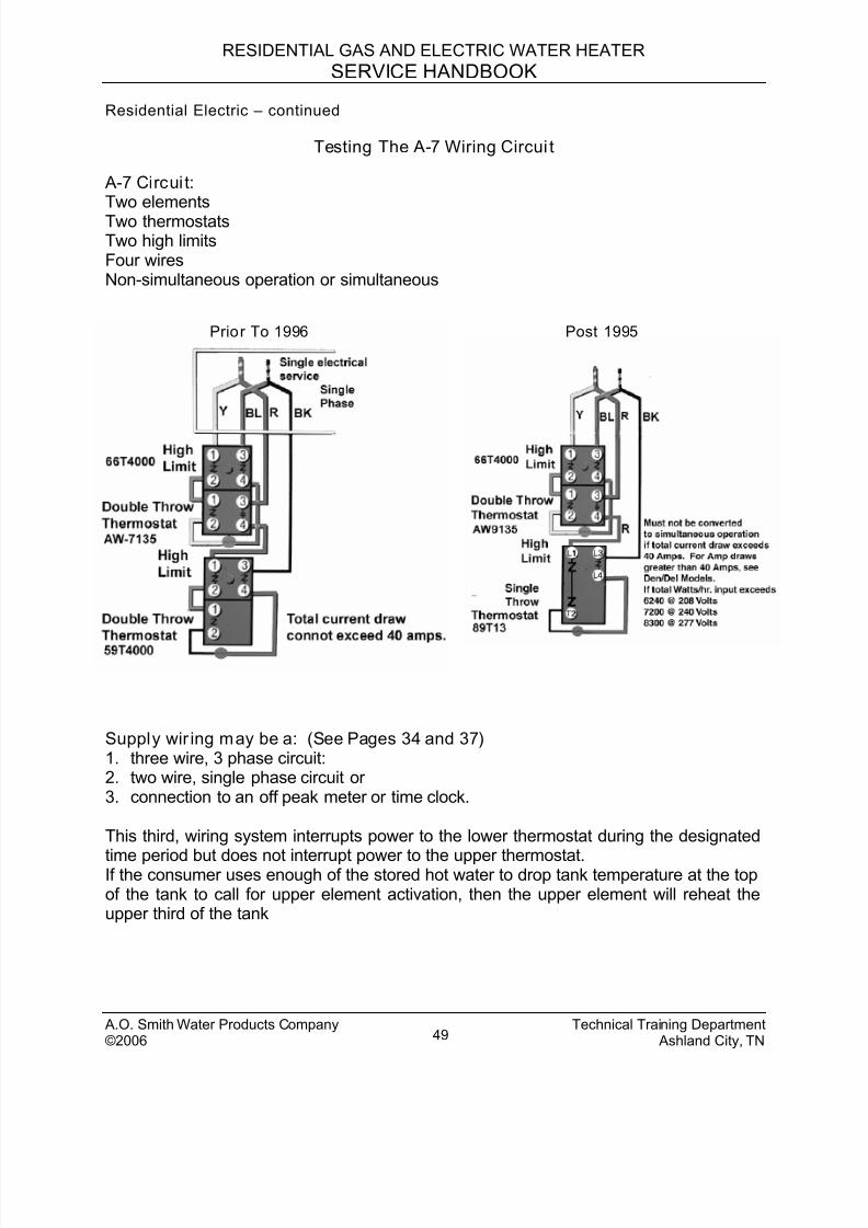
Testing The A-7 Wiring Circui t
A-7 Circui t:Two elementsTwo thermostatsTwo high limitsFour wiresNon-simultaneous operation or simultaneous
Prior To 1996 Post 1995
Supply wir ing may be a: (See Pages 34 and 37)1. three wire, 3 phase circuit:2. two wire, single phase circuit or3. connection to an off peak meter or time clock.
This third, wiring system interrupts power to the lower thermostat during the designated
time period but does not interrupt power to the upper thermostat.If the consumer uses enough of the stored hot water to drop tank temperature at the topof the tank to call for upper element activation, then the upper element will reheat theupper third of the tank
A.O. Smith Water Products Company Technical Training Department©2006 Ashland City, TN49
8/18/2019 A.o. Smith Servicing Guide 320991-000
http://slidepdf.com/reader/full/ao-smith-servicing-guide-320991-000 51/72
RESIDENTIAL GAS AND ELECTRIC WATER HEATER
SERVICE HANDBOOK
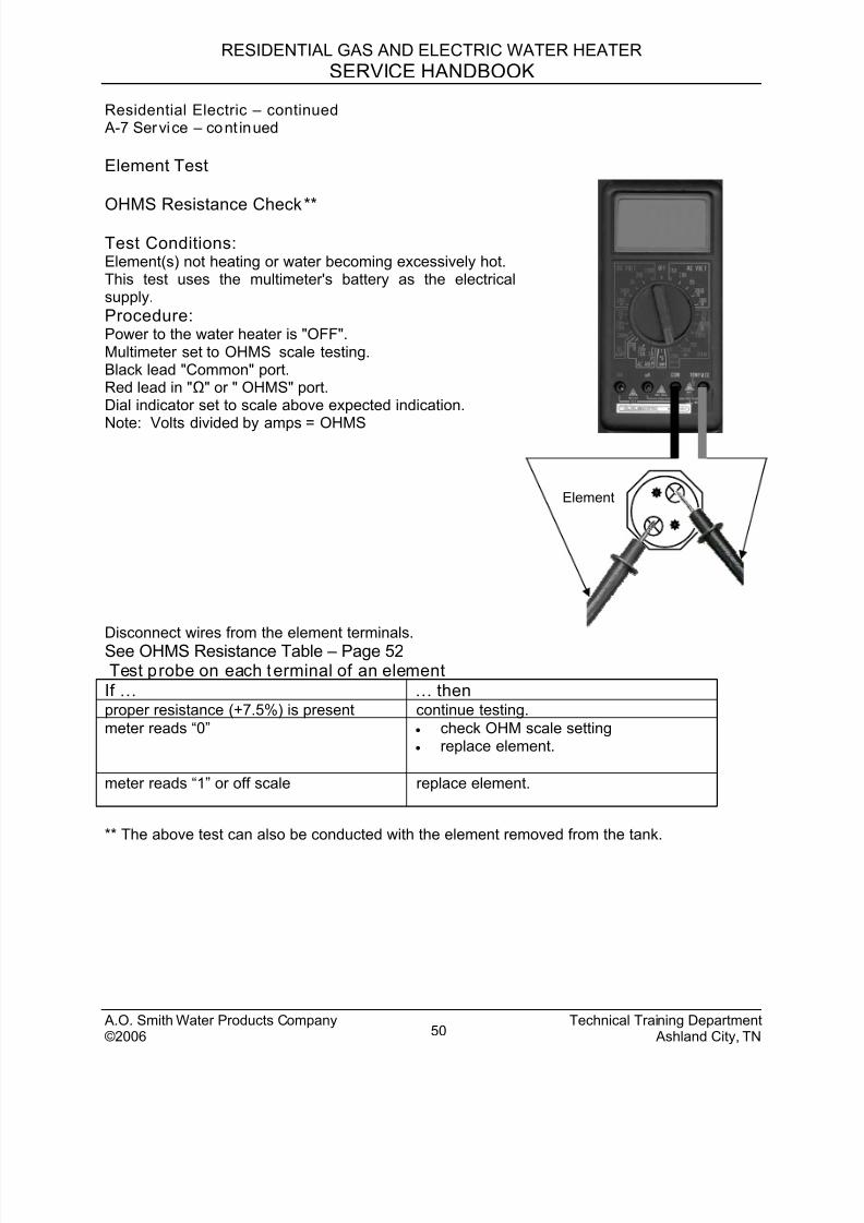
Residential Electric – continued A-7 Service – cont inued
Element Test
OHMS Resistance Check**
Element
Test Conditions:Element(s) not heating or water becoming excessively hot.This test uses the multimeter's battery as the electricalsupply.
Procedure:Power to the water heater is "OFF".Multimeter set to OHMS scale testing.Black lead "Common" port.Red lead in "Ω" or " OHMS" port.Dial indicator set to scale above expected indication.
Note: Volts divided by amps = OHMS
Disconnect wires from the element terminals.
See OHMS Resistance Table – Page 52Test probe on each terminal of an element
If … … thenproper resistance (+7.5%) is present continue testing.
meter reads “0” • check OHM scale setting• replace element.
meter reads “1” or off scale replace element.
** The above test can also be conducted with the element removed from the tank.
A.O. Smith Water Products Company Technical Training Department©2006 Ashland City, TN50
8/18/2019 A.o. Smith Servicing Guide 320991-000
http://slidepdf.com/reader/full/ao-smith-servicing-guide-320991-000 52/72
RESIDENTIAL GAS AND ELECTRIC WATER HEATER
SERVICE HANDBOOK
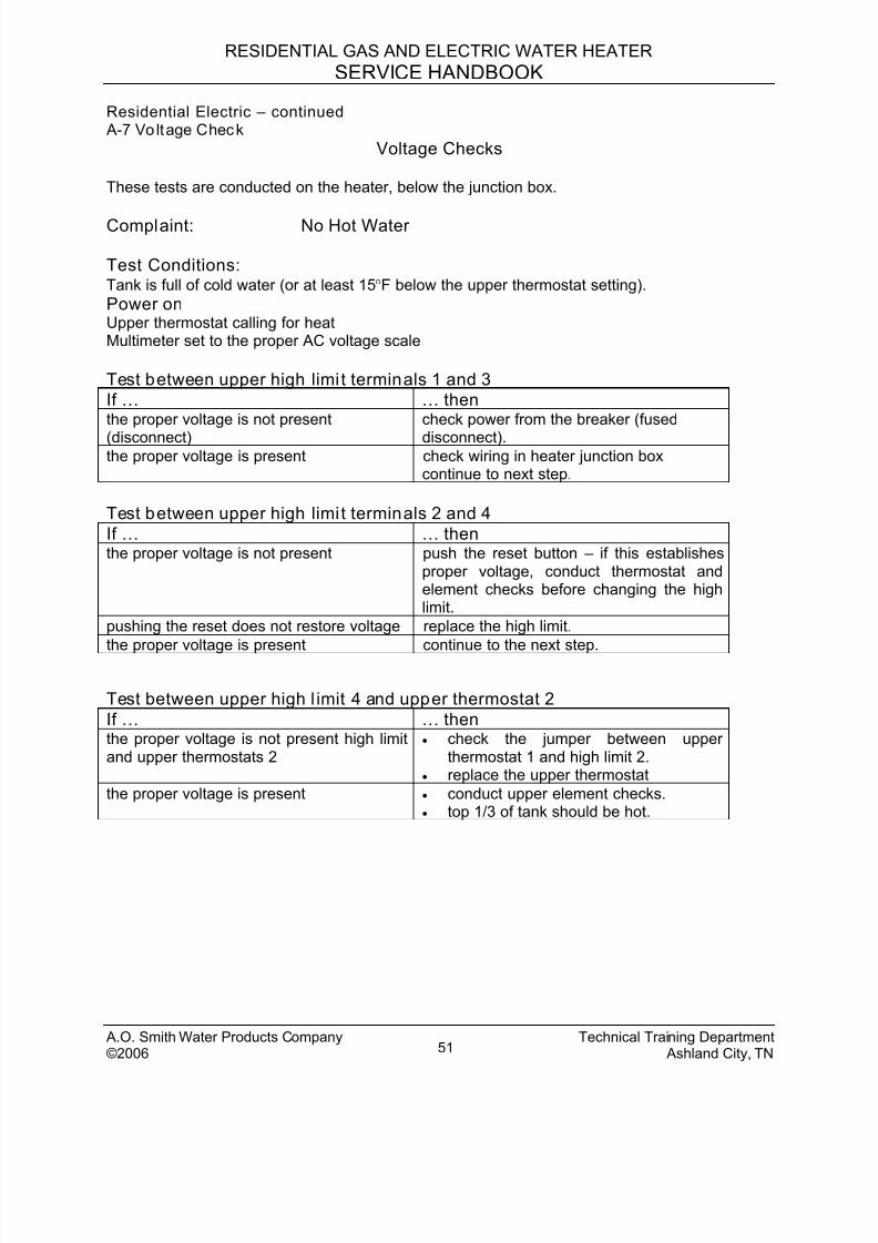
Residential Electric – continued A-7 Vo ltage Check
Voltage Checks
These tests are conducted on the heater, below the junction box.
Complaint: No Hot Water
Test Conditions:Tank is full of cold water (or at least 15°F below the upper thermostat setting).
Power onUpper thermostat calling for heatMultimeter set to the proper AC voltage scale
Test between upper high limi t terminals 1 and 3
If … … thenthe proper voltage is not present
(disconnect)
check power from the breaker (fused
disconnect).the proper voltage is present check wiring in heater junction box
continue to next step.
Test between upper high limi t terminals 2 and 4
If … … thenthe proper voltage is not present push the reset button – if this establishes
proper voltage, conduct thermostat andelement checks before changing the highlimit.
pushing the reset does not restore voltage replace the high limit.
the proper voltage is present continue to the next step.
Test between upper high l imit 4 and upper thermostat 2
If … … thenthe proper voltage is not present high limitand upper thermostats 2
• check the jumper between upperthermostat 1 and high limit 2.
• replace the upper thermostat
the proper voltage is present • conduct upper element checks.• top 1/3 of tank should be hot.
A.O. Smith Water Products Company Technical Training Department©2006 Ashland City, TN51
8/18/2019 A.o. Smith Servicing Guide 320991-000
http://slidepdf.com/reader/full/ao-smith-servicing-guide-320991-000 53/72
RESIDENTIAL GAS AND ELECTRIC WATER HEATER
SERVICE HANDBOOK
Residential Electric – continued A-7 Vo ltage Check - cont inued
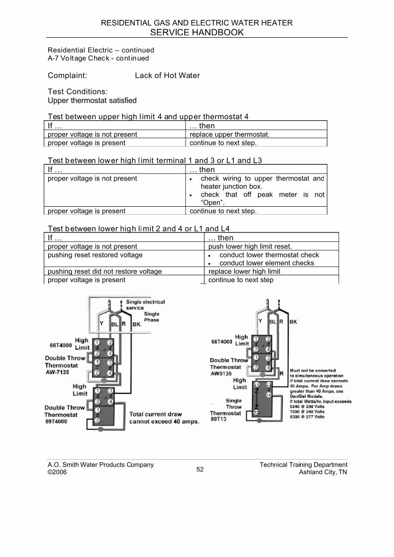
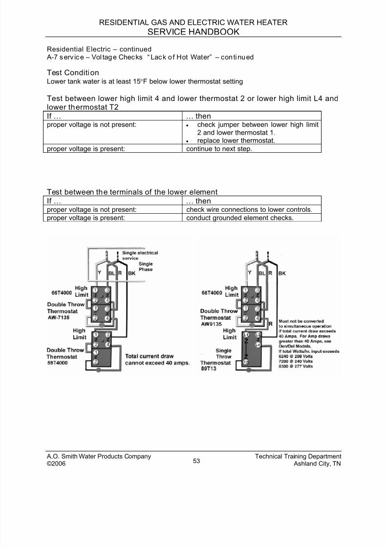
Complaint: Lack of Hot Water
Test Conditions:Upper thermostat satisfied
Test between upper high l imit 4 and upper thermostat 4
If … … thenproper voltage is not present replace upper thermostat.
proper voltage is present continue to next step.
Test between lower high l imit terminal 1 and 3 or L1 and L3
If … … thenproper voltage is not present • check wiring to upper thermostat and
heater junction box.
• check that off peak meter is not“Open”.
proper voltage is present continue to next step.
Test between lower high limit 2 and 4 or L1 and L4
If … … thenproper voltage is not present push lower high limit reset.
pushing reset restored voltage • conduct lower thermostat check• conduct lower element checks
pushing reset did not restore voltage replace lower high limit
proper voltage is present continue to next step
A.O. Smith Water Products Company Technical Training Department©2006 Ashland City, TN52
8/18/2019 A.o. Smith Servicing Guide 320991-000
http://slidepdf.com/reader/full/ao-smith-servicing-guide-320991-000 54/72
RESIDENTIAL GAS AND ELECTRIC WATER HEATER
SERVICE HANDBOOK
Residential Electric – continued A-7 serv ice – Vol tage Checks “ Lack o f Hot Water” – continued
Test ConditionLower tank water is at least 15°F below lower thermostat setting
Test between lower high limit 4 and lower thermostat 2 or lower high limit L4 andlower thermostat T2
If … … thenproper voltage is not present: • check jumper between lower high limit
2 and lower thermostat 1.• replace lower thermostat.
proper voltage is present: continue to next step.
Test between the terminals of the lower elementIf … … thenproper voltage is not present: check wire connections to lower controls.
proper voltage is present: conduct grounded element checks.
A.O. Smith Water Products Company Technical Training Department©2006 Ashland City, TN53
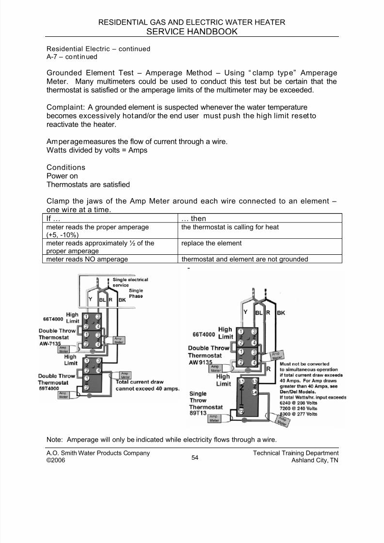
8/18/2019 A.o. Smith Servicing Guide 320991-000
http://slidepdf.com/reader/full/ao-smith-servicing-guide-320991-000 55/72
RESIDENTIAL GAS AND ELECTRIC WATER HEATER
SERVICE HANDBOOK
Residential Electric – continued A-7 – cont inued
Grounded Element Test – Amperage Method – Using “ clamp type” AmperageMeter. Many multimeters could be used to conduct this test but be certain that thethermostat is satisfied or the amperage limits of the multimeter may be exceeded.
Complaint: A grounded element is suspected whenever the water temperaturebecomes excessively hot and/or the end user must push the high limit reset toreactivate the heater.
Amperage measures the flow of current through a wire.Watts divided by volts = Amps
ConditionsPower onThermostats are satisfied
Clamp the jaws of the Amp Meter around each wire connected to an element –one wire at a time.
If … … thenmeter reads the proper amperage(+5, -10%)
the thermostat is calling for heat
meter reads approximately ½ of theproper amperage
replace the element
meter reads NO amperage thermostat and element are not grounded
-
Note: Amperage will only be indicated while electricity flows through a wire.
A.O. Smith Water Products Company Technical Training Department©2006 Ashland City, TN54
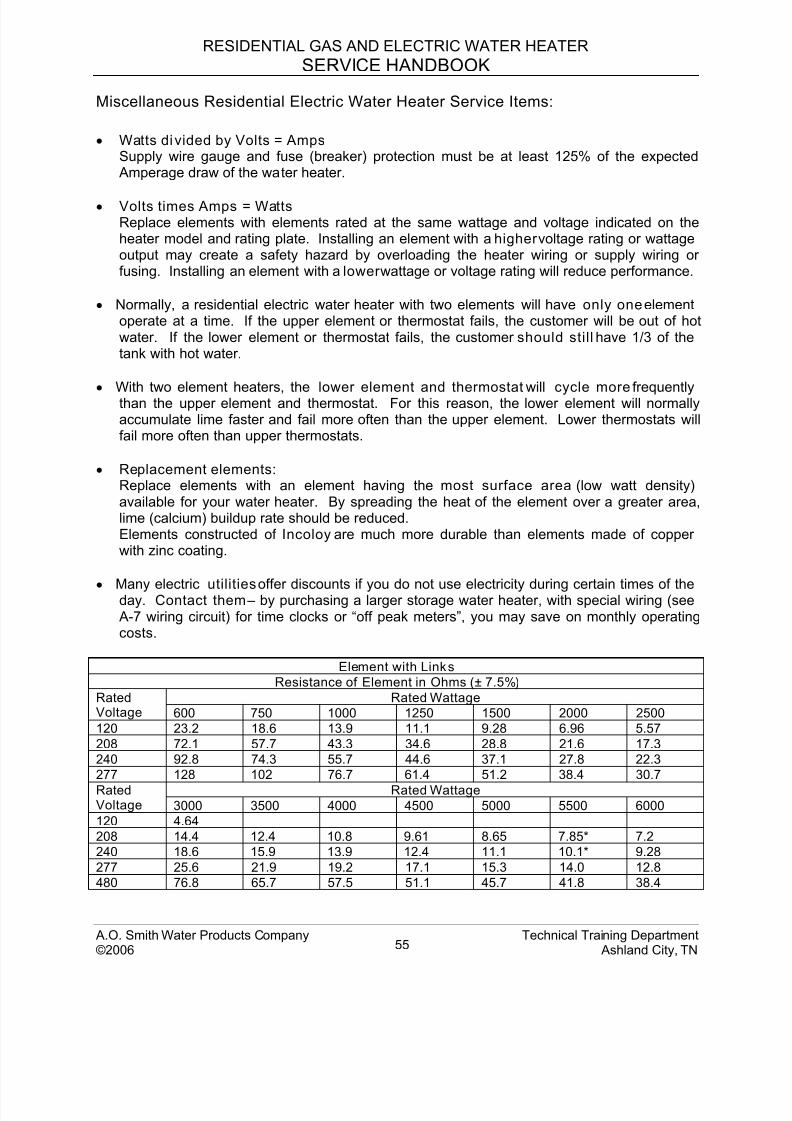
8/18/2019 A.o. Smith Servicing Guide 320991-000
http://slidepdf.com/reader/full/ao-smith-servicing-guide-320991-000 56/72
RESIDENTIAL GAS AND ELECTRIC WATER HEATER
SERVICE HANDBOOK
A.O. Smith Water Products Company Technical Training Department©2006 Ashland City, TN55
Miscellaneous Residential Electric Water Heater Service Items:
• Watts divided by Volts = Amps Supply wire gauge and fuse (breaker) protection must be at least 125% of the expected Amperage draw of the water heater.
• Volts times Amps = WattsReplace elements with elements rated at the same wattage and voltage indicated on theheater model and rating plate. Installing an element with a higher voltage rating or wattageoutput may create a safety hazard by overloading the heater wiring or supply wiring orfusing. Installing an element with a lower wattage or voltage rating will reduce performance.
• Normally, a residential electric water heater with two elements will have only one elementoperate at a time. If the upper element or thermostat fails, the customer will be out of hotwater. If the lower element or thermostat fails, the customer should still have 1/3 of thetank with hot water.
• With two element heaters, the lower element and thermostat will cycle more frequentlythan the upper element and thermostat. For this reason, the lower element will normally
accumulate lime faster and fail more often than the upper element. Lower thermostats willfail more often than upper thermostats.
• Replacement elements:Replace elements with an element having the most surface area (low watt density)available for your water heater. By spreading the heat of the element over a greater area,lime (calcium) buildup rate should be reduced.Elements constructed of Incoloy are much more durable than elements made of copperwith zinc coating.
• Many electric utilities offer discounts if you do not use electricity during certain times of theday. Contact them – by purchasing a larger storage water heater, with special wiring (see
A-7 wiring circuit) for time clocks or “off peak meters”, you may save on monthly operatingcosts.
Element with Links
Resistance of Element in Ohms (± 7.5%)
Rated WattageRatedVoltage 600 750 1000 1250 1500 2000 2500
120 23.2 18.6 13.9 11.1 9.28 6.96 5.57
208 72.1 57.7 43.3 34.6 28.8 21.6 17.3
240 92.8 74.3 55.7 44.6 37.1 27.8 22.3
277 128 102 76.7 61.4 51.2 38.4 30.7
Rated WattageRatedVoltage 3000 3500 4000 4500 5000 5500 6000
120 4.64
208 14.4 12.4 10.8 9.61 8.65 7.85* 7.2
240 18.6 15.9 13.9 12.4 11.1 10.1* 9.28
277 25.6 21.9 19.2 17.1 15.3 14.0 12.8
480 76.8 65.7 57.5 51.1 45.7 41.8 38.4
8/18/2019 A.o. Smith Servicing Guide 320991-000
http://slidepdf.com/reader/full/ao-smith-servicing-guide-320991-000 57/72
RESIDENTIAL GAS AND ELECTRIC WATER HEATER
SERVICE HANDBOOK
A.O. SMITH TECHNICAL BULLETINS
The following are bulletins designed to help service the standard, residential gas andelectric model water heaters. These bulletins and more are available on the A. O. Smithwebsite www.aosmihtwaterheaters.com.
This information is intended to supplement service and maintenance information foundin the heater installation and operation manual.
“Why water heaters leak” information ……………………………..54-55
Index of Technical Bulletins:
Water Hammer.................................................................................. 56Mineral Buildup ................................................................................. 57
Aluminum Hydroxide .........................................................................58Discolored Water...............................................................................59Smelly Water..................................................................................... 60Chlorination Procedure......................................................................61Not Enough Hot Water - Gas ............................................................ 62Not Enough Hot Water – Electric ...................................................... 63Thermal Expansion…………………………………………………....64-65Leaking Temperature and Pressure Relief Valve..............................66
A.O. Smith Water Products Company Technical Training Department©2006 Ashland City, TN56
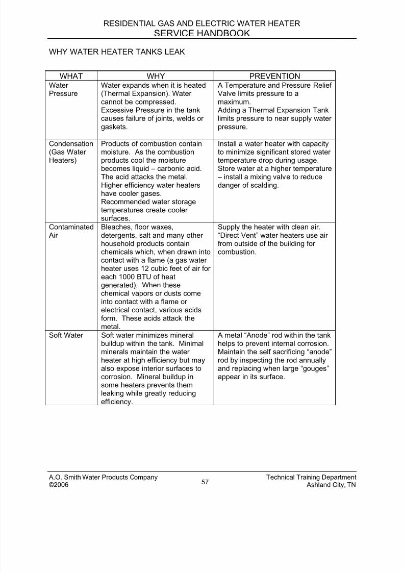
8/18/2019 A.o. Smith Servicing Guide 320991-000
http://slidepdf.com/reader/full/ao-smith-servicing-guide-320991-000 58/72
RESIDENTIAL GAS AND ELECTRIC WATER HEATER
SERVICE HANDBOOK
A.O. Smith Water Products Company Technical Training Department©2006 Ashland City, TN57
WHY WATER HEATER TANKS LEAK
WHAT WHY PREVENTIONWaterPressure
Water expands when it is heated(Thermal Expansion). Water
cannot be compressed.Excessive Pressure in the tankcauses failure of joints, welds orgaskets.
A Temperature and Pressure ReliefValve limits pressure to a
maximum. Adding a Thermal Expansion Tanklimits pressure to near supply waterpressure.
Condensation(Gas WaterHeaters)
Products of combustion containmoisture. As the combustionproducts cool the moisturebecomes liquid – carbonic acid.The acid attacks the metal.Higher efficiency water heatershave cooler gases.
Recommended water storagetemperatures create coolersurfaces.
Install a water heater with capacityto minimize significant stored watertemperature drop during usage.Store water at a higher temperature – install a mixing valve to reducedanger of scalding.
Contaminated Air
Bleaches, floor waxes,detergents, salt and many otherhousehold products containchemicals which, when drawn intocontact with a flame (a gas waterheater uses 12 cubic feet of air foreach 1000 BTU of heatgenerated). When thesechemical vapors or dusts come
into contact with a flame orelectrical contact, various acidsform. These acids attack themetal.
Supply the heater with clean air.“Direct Vent” water heaters use airfrom outside of the building forcombustion.
Soft Water Soft water minimizes mineralbuildup within the tank. Minimalminerals maintain the waterheater at high efficiency but mayalso expose interior surfaces tocorrosion. Mineral buildup insome heaters prevents themleaking while greatly reducing
efficiency.
A metal “Anode” rod within the tankhelps to prevent internal corrosion.Maintain the self sacrificing “anode”rod by inspecting the rod annuallyand replacing when large “gouges”appear in its surface.
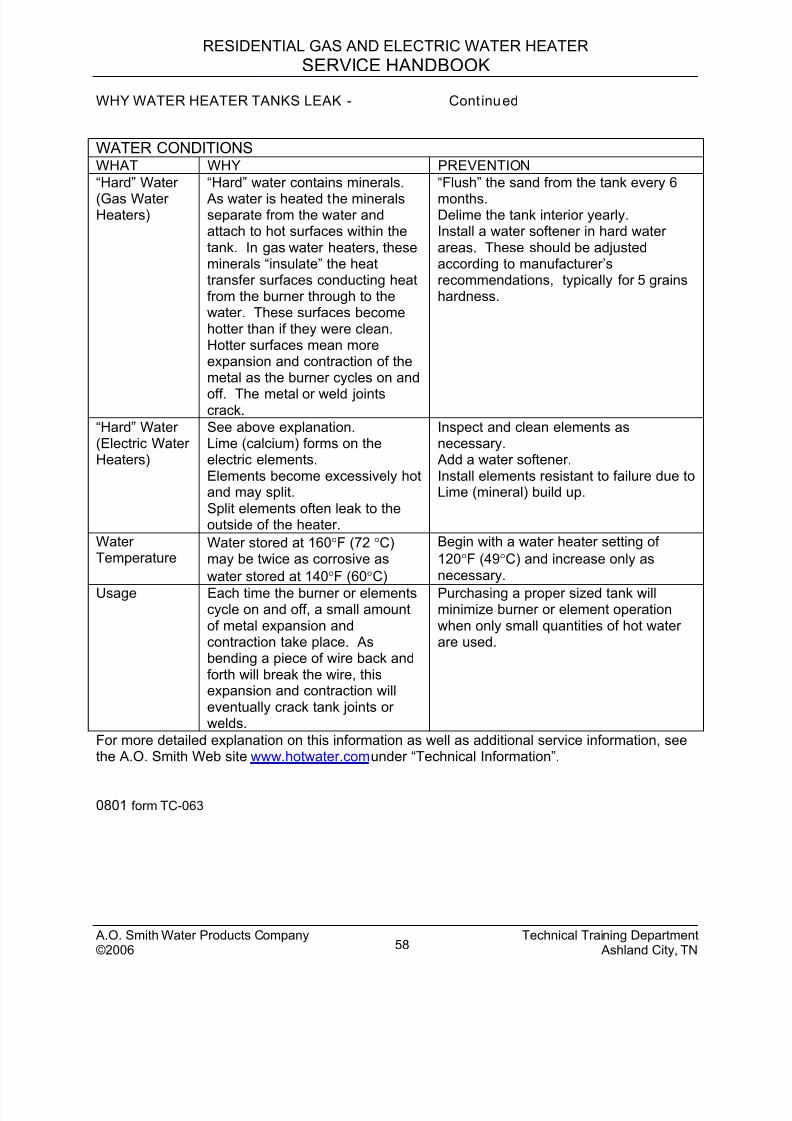
8/18/2019 A.o. Smith Servicing Guide 320991-000
http://slidepdf.com/reader/full/ao-smith-servicing-guide-320991-000 59/72
RESIDENTIAL GAS AND ELECTRIC WATER HEATER
SERVICE HANDBOOK
WHY WATER HEATER TANKS LEAK - Continued
WATER CONDITIONSWHAT WHY PREVENTION
“Hard” Water
(Gas WaterHeaters)
“Hard” water contains minerals.
As water is heated the mineralsseparate from the water andattach to hot surfaces within thetank. In gas water heaters, theseminerals “insulate” the heattransfer surfaces conducting heatfrom the burner through to thewater. These surfaces becomehotter than if they were clean.Hotter surfaces mean moreexpansion and contraction of themetal as the burner cycles on and
off. The metal or weld jointscrack.
“Flush” the sand from the tank every 6
months.Delime the tank interior yearly.Install a water softener in hard waterareas. These should be adjustedaccording to manufacturer’srecommendations, typically for 5 grainshardness.
“Hard” Water(Electric WaterHeaters)
See above explanation.Lime (calcium) forms on theelectric elements.Elements become excessively hotand may split.Split elements often leak to theoutside of the heater.
Inspect and clean elements asnecessary. Add a water softener.Install elements resistant to failure due toLime (mineral) build up.
WaterTemperature
Water stored at 160°F (72 °C)may be twice as corrosive as
water stored at 140°F (60°C)
Begin with a water heater setting of
120°F (49°C) and increase only asnecessary.
Usage Each time the burner or elementscycle on and off, a small amountof metal expansion andcontraction take place. Asbending a piece of wire back andforth will break the wire, thisexpansion and contraction willeventually crack tank joints orwelds.
Purchasing a proper sized tank willminimize burner or element operationwhen only small quantities of hot waterare used.
For more detailed explanation on this information as well as additional service information, seethe A.O. Smith Web site www.hotwater.com under “Technical Information”.
0801 form TC-063
A.O. Smith Water Products Company Technical Training Department©2006 Ashland City, TN58
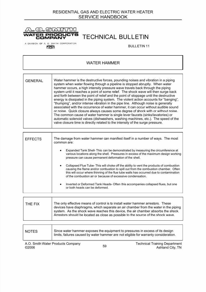
8/18/2019 A.o. Smith Servicing Guide 320991-000
http://slidepdf.com/reader/full/ao-smith-servicing-guide-320991-000 60/72
RESIDENTIAL GAS AND ELECTRIC WATER HEATER
SERVICE HANDBOOK
TECHNICAL BULLETIN
BULLETIN 11
WATER HAMMER
GENERAL Water hammer is the destructive forces, pounding noises and vibration in a pipingsystem when water flowing through a pipeline is stopped abruptly. When waterhammer occurs, a high intensity pressure wave travels back through the pipingsystem until it reaches a point of some relief. The shock wave will then surge backand forth between the point of relief and the point of stoppage until the destructiveenergy is dissipated in the piping system. The violent action accounts for “banging”,
“thumping”, and/or intense vibration in the pipe line. Although noise is generallyassociated with the occurrence of water hammer, it can occur without audible soundor noise. Quick closure always causes some degree of shock with or without noise.The common cause of water hammer is single lever faucets (sinks/lavatories) orautomatic solenoid valves (dishwashers, washing machines, etc.). The speed of thevalve closure time is directly related to the intensity of the surge pressure.
EFFECTS The damage from water hammer can manifest itself in a number of ways. The mostcommon are:
• Expanded Tank Shell - This can be demonstrated by measuring the circumference at
various locations along the shell. Pressures in excess of the maximum design workingpressure can cause permanent deformation of the shell.
• Collapsed Flue Tube - This will choke off the ability to vent the products of combustioncausing the flame and/or combustion to spill out from the combustion chamber. Oftenthis will occur where thinning of the flue tube walls has occurred due to contamination
of the combustion air or because of excessive condensation.
• Inverted or Deformed Tank Heads - Often this accompanies collapsed flues, but oneor both heads can be deformed.
THE FIX The only effective means of control is to install water hammer arrestors. Thesedevices have diaphragms, which separate an air chamber from the water in the pipingsystem. As the shock wave reaches this device, the air chamber absorbs the shock. Arrestors should be located as close as possible to the source of the shock wave.
NOTES Since water hammer exposes the equipment to pressures in excess of its designlimits, failures caused by water hammer are not eligible for warranty consideration.
A.O. Smith Water Products Company Technical Training Department©2006 Ashland City, TN59
8/18/2019 A.o. Smith Servicing Guide 320991-000
http://slidepdf.com/reader/full/ao-smith-servicing-guide-320991-000 61/72
RESIDENTIAL GAS AND ELECTRIC WATER HEATER
SERVICE HANDBOOK
A.O. Smith Water Products Company Technical Training Department
TECHNICAL BULLETIN
BULLETIN 13
MINERAL BUILD-UP
SYMPTOMS • Rumbling • Crackling • Popping
CAUSE With the advent of high input and larger storage tanks in both commercial and
residential heaters, deliming has become a necessity of modern maintenance.Lime (CaCO3), is the most notable factor when discussing water hardness.Lime is present in every water system to some degree across the entireUnited States. Since lime is inversely soluble [the more you heat, the morelime comes out], higher usage, excessive hardness, and increased heatingsurface can lead to a high incidence of “limed-up” heaters.
Symptoms often include a popping of water trapped under lime deposits orthe sizzling of water trapped next to elements, boiling it to steam.
THE FIX Treatment of a “ limed-up“ heater is relatively simple. Since CaCO3 is a base,
the easiest way to dissolve it so it can be flushed from the heater is with anacid. The most commonly used is phosphoric acid at a food-grade level.
Two common treatments marketed by A.O. Smith are Mag-Erad® and Un-
Lime®. Any well-stocked plumbing supply house should have a delimingsolution available.
The directions on the product should be followed explicitly.
NOTES For additional information and instructions in deliming water heaters andboilers, please refer to the following pamphlets available from A.O. Smith:
• Why? When & How: To Remove Water Scale from Tank Type WaterHeaters
• The Mag-Erad® Method of Cleaning Gas Fired Water Heaters
• Up-N-Down™ Transfer Kit
• All About Deliming Coil Type Water Heaters
©2006 Ashland City, TN60
8/18/2019 A.o. Smith Servicing Guide 320991-000
http://slidepdf.com/reader/full/ao-smith-servicing-guide-320991-000 62/72
RESIDENTIAL GAS AND ELECTRIC WATER HEATER
SERVICE HANDBOOK
TECHNICAL BULLETIN
BULLETIN 14
ALUMINUM HYDROXIDE
SYMPTOMS “Crackling”, “gurgling”, or “popping” noises from new water heaters (installed less thansix months).
CAUSE In a few isolated parts of the United States where the water supply has a relatively high pH (8+),water conditions will react with the aluminum anode to form excessive amounts of aluminumhydroxide on the anode and in the bottom of the tank. Aluminum hydroxide looks like “jelly
beads” or a green, blue or gray gel like substance in the heater drain or at faucet aerators.
THE FIX This procedure should only be performed by someone with abilities equal to a licensedtradesman. Aluminum hydroxide can be removed by using one of the methods outlined.
If tank is new with no lime build -up to any degree:
1 Turn off the heater.
2 Remove the anode.
3 Flush the tank thoroughly with water.
4 Replace the aluminum anode (identifiable by smooth surface on plug) with magnesiumanode (identifiable by weld bead on plug).
If the tank is new with lime build-up to any degree: 1 Turn off the heater.
2 Drain the heater.
3 Remove the anode.
4 Add UN-LIME to the tank. 20-40 gallon models (use 3 gallons of UN-LIME)41-65 gallon models (use 5 gallons of UN-LIME)66-100 gallon models (use 7 gallons of UN-LIME)
(On electric models, be certain the lower element is immersed in solution.) 5 Heat the UN-LIME to a temperature between 140°F to 160°F.
• GAS - Heat for 7 to 10 minutes. • ELECTRIC - Power off and remove the yellow wire from terminal 2 on the upper thermostat.
Move the red wire from terminal 4 of the upper thermostat to terminal 2 of the upperthermostat. This allows operation of the lower element only. Restore power to the heater.Be certain that only the lower element is operating. Heat for 7 to 10 minutes.
6 Shut off the water heater.
7 Allow the heated UN-LIME to stand for up to 12 minutes.
8 Drain and flush the tank. Caution: UN-LIME will still be hot.
9 Replace the original aluminum anode with a magnesium anode.
10 Fill the system with water.
11 On electric models, return the wiring to its original configuration.
12 Turn heater fuel “ON”.
NOTE Since aluminum hydroxide is a product of a chemical reaction dependent on the water condition,
any treatment is not considered warranty related.
A.O. Smith Water Products Company Technical Training Department©2006 Ashland City, TN61
8/18/2019 A.o. Smith Servicing Guide 320991-000
http://slidepdf.com/reader/full/ao-smith-servicing-guide-320991-000 63/72
RESIDENTIAL GAS AND ELECTRIC WATER HEATER
SERVICE HANDBOOK
TECHNICAL BULLETIN
BULLETIN 21
DISCOLORED WATER
SYMPTOMS Rusty, brown, black, or yellow water appearing in the hot water.
CAUSE Complaints of discolored water are commonly blamed on water heaters andstorage tanks, but in fact, it is a rare occurrence for today’s high quality glasslined tanks to have a lining failure significant enough to allow water to contactenough bare metal to discolor the contents of even a small tank.
The most common cause of “rusty” water is a non-toxic iron reducing bacteria,scientifically termed Crenothrix, Leptothrix, and Gallionella. Iron bacteria iscommonly found in soil, water wells, water treatment plants and waterdistribution piping systems where soluble iron exceeds 0.2 ppm, higher levelsmake conditions even more favorable. Soluble iron in the water provides foodfor the bacteria. Rusty discolored water is the end result of the bacteria feedingprocess. Water heaters and storage tanks usually require new anode rods aspresence of iron bacteria contributes to premature anode failure.
The requirements for the bacteria to thrive are:
• Elevated level of iron and manganese in the water• Water with little or no dissolved oxygen
• Temperatures below 138 °F
Items that can increase the potential for this bacteria are:
• Water softeners
• Well water
• Long periods of no water movement
TREATMENT The simplest treatment available is shock-chlorination of the system. This is asurface treatment, and often requires repeated trials in heavily infected
systems. The chlorination of a system requires that you follow each stepexplicitly to avoid an un-treated portion of the piping system from reinfectinganother part. See Bulletin 23 for the chlorination procedure.
NOTE Since rusty water is caused by a bacteria presence and is not caused by thewater heater, any treatment would not be considered warranty related.
A.O. Smith Water Products Company Technical Training Department©2006 Ashland City, TN62
8/18/2019 A.o. Smith Servicing Guide 320991-000
http://slidepdf.com/reader/full/ao-smith-servicing-guide-320991-000 64/72
RESIDENTIAL GAS AND ELECTRIC WATER HEATER
SERVICE HANDBOOK
TECHNICAL BULLETIN
BULLETIN 22
SMELLY WATER
CAUSE The most common cause of “smelly water” is a non-toxic sulfate reducingbacteria, scientifically termed Divibrio Sulfurcans. This bacteria often entersthe water system through construction or a break in ground piping. Thebacteria creates the energy it needs to survive by converting sulfate (SO4) tohydrogen sulfide (H2S) gas you smell in the water.
Hydrogen sulfide gas is distinctive because of its rotten egg-like stench. Its
presence can severely affect the taste as well as the odor of the water.Occasionally this bacteria can be accompanied by black deposits, the resultof pipe and fitting corrosion. In extremely high concentrations, hydrogensulfide gas can be toxic though the gas is detectable long before harmfullevels are reached.
The requirements for the bacteria to thrive are: a) an elevated level of sulfur inthe water, b) activated hydrogen from cathodic reactions within the tank, c)
water with little or no dissolved oxygen, d) and temperatures below 138°F.
Items that can increase the potential for this bacteria are: a) water softeners,b) well water, c) and long periods of no water movement.
Other factors that may contribute to smelly water:
• Chlorides of Magnesium and Calcium leave a bitter taste.
• Chloride of Sodium produces a salty taste.
• Sulfates (50 ppm) give a medicinal taste.
• Carbon Dioxide in a low pH water gives fizzy water.
• Iron and tannic waters also give a bad taste and odor.
TREATMENT The simplest treatment available is the shock-chlorination of the system. Thisis a surface treatment, and often requires repeated trials in heavily infectedsystems. The chlorination of a system requires that you follow each step
explicitly to avoid an un-treated portion of the piping system from reinfectinganother part. See Bulletin 23 for the chlorination procedure. Longer lastingsolutions include chlorination or aeration of the water supply.
NOTE Since smelly water is caused by a bacteria presence and is not caused by thewater heater, any treatment would not be considered warranty related.
A.O. Smith Water Products Company Technical Training Department©2006 Ashland City, TN63
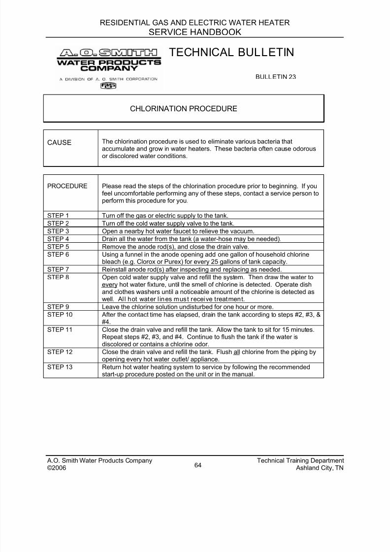
8/18/2019 A.o. Smith Servicing Guide 320991-000
http://slidepdf.com/reader/full/ao-smith-servicing-guide-320991-000 65/72
RESIDENTIAL GAS AND ELECTRIC WATER HEATER
SERVICE HANDBOOK
TECHNICAL BULLETIN
BULLETIN 23
CHLORINATION PROCEDURE
CAUSE The chlorination procedure is used to eliminate various bacteria thataccumulate and grow in water heaters. These bacteria often cause odorousor discolored water conditions.
PROCEDURE Please read the steps of the chlorination procedure prior to beginning. If you
feel uncomfortable performing any of these steps, contact a service person toperform this procedure for you.
STEP 1 Turn off the gas or electric supply to the tank.
STEP 2 Turn off the cold water supply valve to the tank.
STEP 3 Open a nearby hot water faucet to relieve the vacuum.
STEP 4 Drain all the water from the tank (a water-hose may be needed).
STEP 5 Remove the anode rod(s), and close the drain valve.
STEP 6 Using a funnel in the anode opening add one gallon of household chlorinebleach (e.g. Clorox or Purex) for every 25 gallons of tank capacity.
STEP 7 Reinstall anode rod(s) after inspecting and replacing as needed.
STEP 8 Open cold water supply valve and refill the system. Then draw the water toevery hot water fixture, until the smell of chlorine is detected. Operate dish
and clothes washers until a noticeable amount of the chlorine is detected aswell. Al l hot water l ines must receive treatment.
STEP 9 Leave the chlorine solution undisturbed for one hour or more.
STEP 10 After the contact time has elapsed, drain the tank according to steps #2, #3, .
STEP 11 Close the drain valve and refill the tank. Allow the tank to sit for 15 minutes.Repeat steps #2, #3, and #4. Continue to flush the tank if the water isdiscolored or contains a chlorine odor.
STEP 12 Close the drain valve and refill the tank. Flush all chlorine from the piping byopening every hot water outlet/ appliance.
STEP 13 Return hot water heating system to service by following the recommendedstart-up procedure posted on the unit or in the manual.
A.O. Smith Water Products Company Technical Training Department©2006 Ashland City, TN64

8/18/2019 A.o. Smith Servicing Guide 320991-000
http://slidepdf.com/reader/full/ao-smith-servicing-guide-320991-000 66/72
RESIDENTIAL GAS AND ELECTRIC WATER HEATER
SERVICE HANDBOOK
A.O. Smith Water Products Company Technical Training Department©2006 Ashland City, TN65
TECHNICAL BULLETIN
BULLETIN 35
NOT ENOUGH HOT WATER - GAS
CAUSE Not enough hot water complaints are becoming more frequent in the water heaterindustry. This increase was triggered when changes required by our regulatoryagencies were implemented. For example, heaters are now factory preset at alower temperature and inlet tubes have been shortened. While lower temperaturessettings reduce the burn rate, and shorter dip tubes guard against stacking, bothaffect the amount of hot water a water heater can supply. The following test willhelp determine if a water heater is supplying the intended amount of hot water and
will help pinpoint any problems that exist.
TEST Please read all the steps of the test prior to beginning. If you feel uncomfortableperforming any of these steps, contact a service person to conduct this test for you.
STEP 1 At the faucet nearest to the water heater, time (in seconds) how long it takes to fill a1 gallon bucket (flow rate).
Gallon per minute (gpm) = 60 seconds / seconds to fill a 1 gallon bucketIf the bucket fills in: 10 sec = 6 gpm
12 sec = 5 gpm
15 sec = 4 gpm20 sec = 3 gpm24 sec = 2.5 gpm
STEP 2 Turn thermostat dial on the water heater so the arrow points to “A” position.
STEP 3 Run about 15 gallons of hot water from the nearest faucet. Shut water off.
STEP 4 Water heater should complete heating 15 gallons in approximately 20-35 minutes.
STEP 5 At a nearby faucet using a candy thermometer, measure the hot water temperature.
STEP 6 The temperature should fall between 120°F to 140°F.
STEP 7 Continue running the hot water until 60% of the tank capacity is depleted:CAPACITY DEPLETE 30 gallons 18 gallons40 gallons 24 gallons50 gallons 30 gallons75 gallons 45 gallons
100 gallons 60 gallons
STEP 8 At the same faucet using a candy thermometer, measure the water temperature.
STEP 9 The temperature should be about 30°F below the temperature in step 6.
THE FIX Step 6 - if the temperature was not within range, check the thermostat.
Step 9 - if more than 30 °F was lost, check the dip tube.
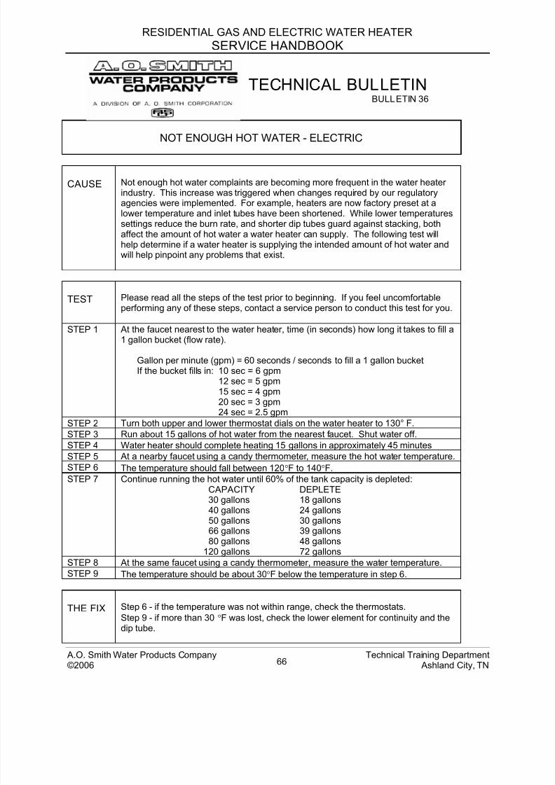
8/18/2019 A.o. Smith Servicing Guide 320991-000
http://slidepdf.com/reader/full/ao-smith-servicing-guide-320991-000 67/72
RESIDENTIAL GAS AND ELECTRIC WATER HEATER
SERVICE HANDBOOK
TECHNICAL BULLETIN
BULLETIN 36
NOT ENOUGH HOT WATER - ELECTRIC
CAUSE Not enough hot water complaints are becoming more frequent in the water heaterindustry. This increase was triggered when changes required by our regulatoryagencies were implemented. For example, heaters are now factory preset at alower temperature and inlet tubes have been shortened. While lower temperaturessettings reduce the burn rate, and shorter dip tubes guard against stacking, bothaffect the amount of hot water a water heater can supply. The following test willhelp determine if a water heater is supplying the intended amount of hot water andwill help pinpoint any problems that exist.
TEST Please read all the steps of the test prior to beginning. If you feel uncomfortableperforming any of these steps, contact a service person to conduct this test for you.
STEP 1 At the faucet nearest to the water heater, time (in seconds) how long it takes to fill a1 gallon bucket (flow rate).
Gallon per minute (gpm) = 60 seconds / seconds to fill a 1 gallon bucketIf the bucket fills in: 10 sec = 6 gpm
12 sec = 5 gpm15 sec = 4 gpm20 sec = 3 gpm
24 sec = 2.5 gpm STEP 2 Turn both upper and lower thermostat dials on the water heater to 130° F.
STEP 3 Run about 15 gallons of hot water from the nearest faucet. Shut water off.
STEP 4 Water heater should complete heating 15 gallons in approximately 45 minutes
STEP 5 At a nearby faucet using a candy thermometer, measure the hot water temperature.
STEP 6 The temperature should fall between 120°F to 140°F.
STEP 7 Continue running the hot water until 60% of the tank capacity is depleted:CAPACITY DEPLETE 30 gallons 18 gallons40 gallons 24 gallons50 gallons 30 gallons66 gallons 39 gallons80 gallons 48 gallons
120 gallons 72 gallons STEP 8 At the same faucet using a candy thermometer, measure the water temperature.
STEP 9 The temperature should be about 30°F below the temperature in step 6.
THE FIX Step 6 - if the temperature was not within range, check the thermostats.
Step 9 - if more than 30 °F was lost, check the lower element for continuity and thedip tube.
A.O. Smith Water Products Company Technical Training Department©2006 Ashland City, TN66
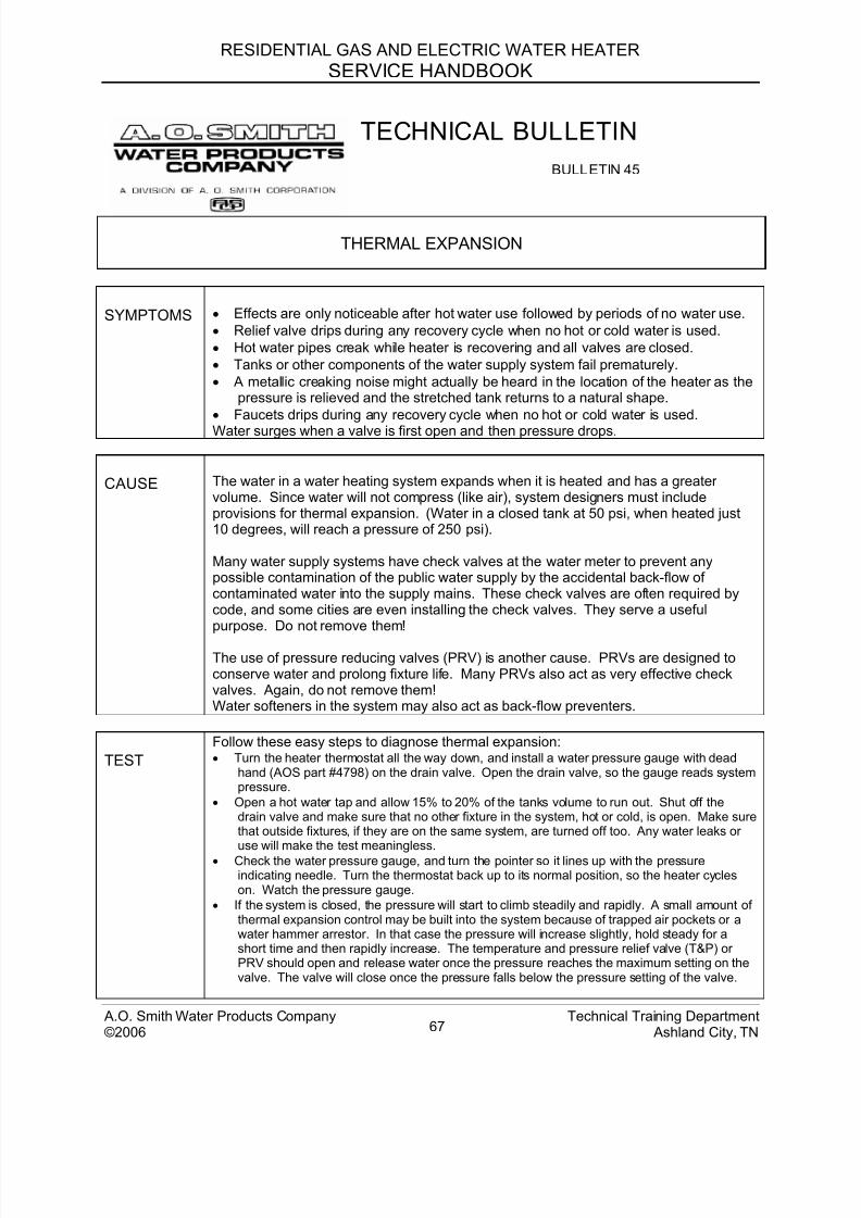
8/18/2019 A.o. Smith Servicing Guide 320991-000
http://slidepdf.com/reader/full/ao-smith-servicing-guide-320991-000 68/72
RESIDENTIAL GAS AND ELECTRIC WATER HEATER
SERVICE HANDBOOK
TECHNICAL BULLETIN
BULLETIN 45
THERMAL EXPANSION
SYMPTOMS • Effects are only noticeable after hot water use followed by periods of no water use.
• Relief valve drips during any recovery cycle when no hot or cold water is used.
• Hot water pipes creak while heater is recovering and all valves are closed.
• Tanks or other components of the water supply system fail prematurely.
• A metallic creaking noise might actually be heard in the location of the heater as thepressure is relieved and the stretched tank returns to a natural shape.
• Faucets drips during any recovery cycle when no hot or cold water is used.
Water surges when a valve is first open and then pressure drops.
CAUSE The water in a water heating system expands when it is heated and has a greatervolume. Since water will not compress (like air), system designers must includeprovisions for thermal expansion. (Water in a closed tank at 50 psi, when heated just10 degrees, will reach a pressure of 250 psi).
Many water supply systems have check valves at the water meter to prevent anypossible contamination of the public water supply by the accidental back-flow ofcontaminated water into the supply mains. These check valves are often required bycode, and some cities are even installing the check valves. They serve a usefulpurpose. Do not remove them!
The use of pressure reducing valves (PRV) is another cause. PRVs are designed toconserve water and prolong fixture life. Many PRVs also act as very effective checkvalves. Again, do not remove them!Water softeners in the system may also act as back-flow preventers.
TEST
Follow these easy steps to diagnose thermal expansion: • Turn the heater thermostat all the way down, and install a water pressure gauge with dead
hand (AOS part #4798) on the drain valve. Open the drain valve, so the gauge reads systempressure.
• Open a hot water tap and allow 15% to 20% of the tanks volume to run out. Shut off thedrain valve and make sure that no other fixture in the system, hot or cold, is open. Make surethat outside fixtures, if they are on the same system, are turned off too. Any water leaks oruse will make the test meaningless.
• Check the water pressure gauge, and turn the pointer so it lines up with the pressureindicating needle. Turn the thermostat back up to its normal position, so the heater cycleson. Watch the pressure gauge.
• If the system is closed, the pressure will start to climb steadily and rapidly. A small amount ofthermal expansion control may be built into the system because of trapped air pockets or awater hammer arrestor. In that case the pressure will increase slightly, hold steady for ashort time and then rapidly increase. The temperature and pressure relief valve (T&P) orPRV should open and release water once the pressure reaches the maximum setting on thevalve. The valve will close once the pressure falls below the pressure setting of the valve.
A.O. Smith Water Products Company Technical Training Department©2006 Ashland City, TN67
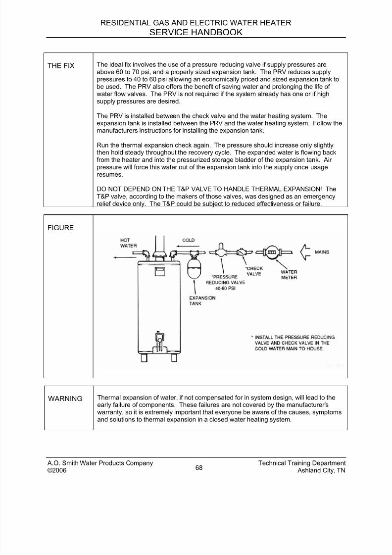
8/18/2019 A.o. Smith Servicing Guide 320991-000
http://slidepdf.com/reader/full/ao-smith-servicing-guide-320991-000 69/72
RESIDENTIAL GAS AND ELECTRIC WATER HEATER
SERVICE HANDBOOK
THE FIX The ideal fix involves the use of a pressure reducing valve if supply pressures areabove 60 to 70 psi, and a properly sized expansion tank. The PRV reduces supplypressures to 40 to 60 psi allowing an economically priced and sized expansion tank tobe used. The PRV also offers the benefit of saving water and prolonging the life of
water flow valves. The PRV is not required if the system already has one or if highsupply pressures are desired.
The PRV is installed between the check valve and the water heating system. Theexpansion tank is installed between the PRV and the water heating system. Follow themanufacturers instructions for installing the expansion tank.
Run the thermal expansion check again. The pressure should increase only slightlythen hold steady throughout the recovery cycle. The expanded water is flowing backfrom the heater and into the pressurized storage bladder of the expansion tank. Airpressure will force this water out of the expansion tank into the supply once usageresumes.
DO NOT DEPEND ON THE T&P VALVE TO HANDLE THERMAL EXPANSION! The
T&P valve, according to the makers of those valves, was designed as an emergencyrelief device only. The T&P could be subject to reduced effectiveness or failure.
FIGURE
WARNING Thermal expansion of water, if not compensated for in system design, will lead to theearly failure of components. These failures are not covered by the manufacturer’swarranty, so it is extremely important that everyone be aware of the causes, symptomsand solutions to thermal expansion in a closed water heating system.
A.O. Smith Water Products Company Technical Training Department©2006 Ashland City, TN68
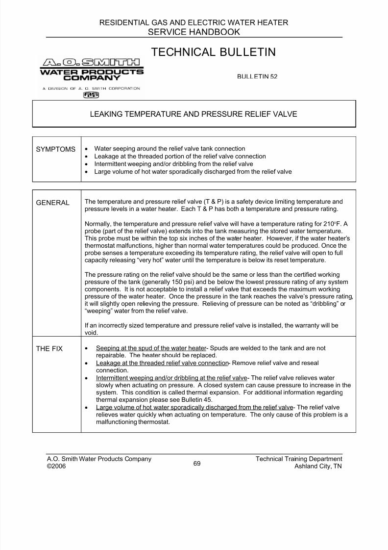
8/18/2019 A.o. Smith Servicing Guide 320991-000
http://slidepdf.com/reader/full/ao-smith-servicing-guide-320991-000 70/72

8/18/2019 A.o. Smith Servicing Guide 320991-000
http://slidepdf.com/reader/full/ao-smith-servicing-guide-320991-000 71/72
RESIDENTIAL GAS AND ELECTRIC WATER HEATER
SERVICE HANDBOOK
PLEASE DO NOT RETURN THIS INFORMATION UNTIL YOU HAVE HAD THIS
SERVICE HANDBOOK AT LEAST 6 MONTHS.
Please assist us in making this Service Handbook more useful to you by completing and
returning this page.
Date Service Handbook Received: ___month______year
Date Returned to the Technical Training Department: ___month____year
From front cover: Service Handbook part number: __________.
I have used this handbook _______ times to help service these water heaters.
I would rate this handbook as: no benefit, 1, 2, 3, Okay 4, 5, 6 Very beneficial.
Comments:_____________________________________________________________
This handbook saved me: no,1, 2, 3, some 4, 5, 6, significant, time on these service calls.
Comments:______________________________________________________________
I feel that this handbook is: difficult, 1, 2, 3 okay 4, 5, 6, very easy, to understand and use.
Comments:______________________________________________________________
I Would or Would NOT recommend this book to other service agents. (circle answer).
Comments:______________________________________________________________
Other methods of receiving service information or training that I would like to have available:
____ Internet Based Training ____ Service Computer Disc (CDs)
____ Internet correspondence ____ Prefer written literature
____ Other ______________________________
Additional comments or suggestions to improve this service handbook:
Please cut out this page and return your comments to:Technical Training Department - FAX 1-615-792-2135
A.O. Smith Water Products Company Technical Training Department©2006 Ashland City, TN70
8/18/2019 A.o. Smith Servicing Guide 320991-000
http://slidepdf.com/reader/full/ao-smith-servicing-guide-320991-000 72/72