Embed Size (px)
Citation preview
commercial gas water heatersinstruction manual
PRINTED 0812 197283-004
place these instructions adjacent to heater and notify owner to keep for future reference.
models Btr 120 - 400(a)Btrc 120 - 400(a)
series 118/119installation - operation - serVice - maintenance - limited warranty
Read and understand this instructionmanual and the safety messagesherein before installing, operating orservicing this water heater.
Failure to follow these instructions andsafety messages could result in deathor serious injury.
This manual must remain with thewater heater.
500 Tennessee Waltz ParkwayAshland City, TN 37015
Low Lead Content
Thank you for buying this energy efficient water heater. We appreciate your confidence in our products.
WARNING: If the information in theseinstructions is not followed exactly, a fireor explosion may result causing propertydamage, personal injury or death.
Do not store or use gasoline or otherflammable vapors and liquids in thevicinity of this or any other appliance.
WHAT TO DO IF YOU SMELL GAS:Do not try to light any appliance.Do not touch any electrical switch; donot use any phone in your building.Immediately call your gas supplierfrom a neighbor’s phone. Follow thegas supplier’s instructions.
If you cannot reach your gas supplier,call the fire department.
Installation and service must beperformed by a qualified installer,service agency or the gas supplier.
••
•
•
2
Air From Other Indoor Spaces ........................................................ 18
Technical Data Venting ..............................................................19-20
Mechanical Venting ......................................................................... 21
WATER HEATER INsTAllATIoN ................................................. 21-24
Water Line Connections .................................................................. 21
T&P Valve Discharge Pipe .............................................................. 21
Installation Diagrams - Top Inlet/outlet Usage ............................... 22
Heater Wiring .................................................................................. 23
Gas Piping ....................................................................................... 24
Gas line leak Testing .................................................................... 24
Purging ............................................................................................ 24
oPERATIoN ........................................................................................ 25
Prior to start Up .............................................................................. 25
sEqUENCE of oPERATIoN ............................................................ 25
Sequence of Operation Flow Chart ................................................ 26
lighting & operation labels ...................................................... 27-28
Adjustments..................................................................................... 29
Checking Venting ............................................................................ 29
Checking the Input .......................................................................... 29
mAINTENANCE ................................................................................... 31
Venting System ............................................................................... 31
Remote storage Tank Temperature Control ................................... 31
Temperature-Pressure Relief Valve Test ........................................ 31
Anode Rod Inspection................................................................ 31-32
Draining and flushing ..................................................................... 32
Recommended Procedure for Periodic Removal or Lime Deposits from the Tank Type Commercial Water Heaters ............................ 32
DeLiming Solvents .......................................................................... 33
Tank Cleanout Procedure ............................................................... 33
Deliming Using flo-Jug method ................................................33-34
Pilot Burner...................................................................................... 34
main Burner ..................................................................................... 35
Gas Control Valve ........................................................................... 35
SeRVICe ............................................................................................. 35
electrical Servicing ......................................................................... 35
TRoUBlEsHooTING ......................................................................... 36
Ignition module ................................................................................ 36
flue Damper .................................................................................... 36
effikal RVGP-KSF Series Flue Damper Trouble Shooting Guide ........ 37
Troubleshooting Checklist ............................................................... 38
foR yoUR INfoRmATIoN ................................................................ 39
start up Conditions ......................................................................... 39
operational Conditions ................................................................... 39
WATER PIPING DIAGRAms ..........................................................40-54
MANIFOLD KITS ................................................................................. 55
NoTEs ............................................................................................56-58
WARRANTy ........................................................................................ 59
taBle of contents
SAFe INSTALLATION, USe AND SeRVICe ........................................ 3
APPROVALS .......................................................................................... 3
GENERAl sAfETy INfoRmATIoN .................................................4-5
Precautions ....................................................................................... 5
Grounding Instructions ...................................................................... 5
Hydrogen Gas flammable ................................................................ 5
INTRoDUCTIoN ................................................................................... 6
Abbreviations Used ........................................................................... 6
Qualifications .................................................................................... 6
Preparing for the Installation ............................................................. 6
fEATUREs AND ComPoNENTs ........................................................ 7
The Eliminator (self Cleaning system) ............................................. 7
High Limit Switch ............................................................................... 7
electronic Ignition Control ................................................................. 7
Automatic Flue Damper .................................................................... 7
Uncrating ........................................................................................... 7
INsTAllATIoN CoNsIDERATIoNs ............................................... 8-12
Rough In Dimensions ........................................................................ 8
Locating The Water Heater ............................................................. 10
Clearances ...................................................................................... 10
NSF Leg Kit ......................................................................................11
Insulation Blanket .............................................................................11
Hard Water .......................................................................................11
Circulation Pumps .......................................................................11-12
High Altitude Installations ............................................................... 12
INsTAllATIoN REqUIREmENTs ..................................................... 13
Gas supply systems ....................................................................... 13
supply Gas Regulator ..................................................................... 13
Power supply .................................................................................. 13
Water Temperature Control and Mixing Valves .............................. 13
Dishwashing Machines ................................................................... 14
Closed Water systems .................................................................... 14
Thermal Expansion ......................................................................... 14
Temperature-Pressure Relief Valve........................................... 14-15
Contaminated Air ............................................................................ 15
Air Requirements ............................................................................ 15
Unconfined Space ........................................................................... 16
Confined Space ............................................................................... 16
VeNTING INSTALLATION .................................................................. 16
Venting ............................................................................................ 16
Vent Reducer .................................................................................. 16
multiple Heater manifold ................................................................. 17
Fresh Air Opening for Confined Spaces ......................................... 17
outdoor Air Through Two openings ............................................... 17
outdoor Air Through one opening ................................................ 17
Outdoor Air Through Two Horizontal Ducts .................................... 17
Outdoor Air Through Two Vertical Ducts ........................................ 18
3
safe installation, use and serVice
The proper installation, use and servicing of this water heater is extremely important to your safety and the safety of others.Many safety-related messages and instructions have been provided in this manual and on your own water heater to warn you and others of a potential injury hazard. Read and obey all safety messages and instructions throughout this manual. It is very important that the meaning of each safety message is understood by you and others who install, use, or service this water heater.
All safety messages will generally tell you about the type of hazard, what can happen if you do not follow the safety message, and how to avoid the risk of injury.The California Safe Drinking Water and Toxic enforcement Act requires the Governor of California to publish a list of substances known to the State of California to cause cancer, birth defects, or other reproductive harm, and requires businesses to warn of potential exposure to such substances.This product contains a chemical known to the State of California to cause cancer, birth defects, or other reproductive harm. This water heater can cause low level exposure to some of the substances listed in the Act.
DANGER
WARNING
CAUTION
CAUTION
DANGER indicates an imminentlyhazardous situation which, if not avoided,will result in injury or death.
This is the safety alert symbol. It is used to alert you topotential personal injury hazards. Obey all safetymessages that follow this symbol to avoid possibleinjury or death.
WARNING indicates a potentially hazardoussituation which, if not avoided, could resultin injury or death.
CAUTION indicates a potentially hazardoussituation which, if not avoided, could result inminor or moderate injury.
CAUTION used without the safety alertsymbol indicates a potentially hazardoussituation which, if not avoided, could result inproperty damage.
approVals
note: ASMe construction is optional on the water heaters covered in this manual.
Low Lead Content
4
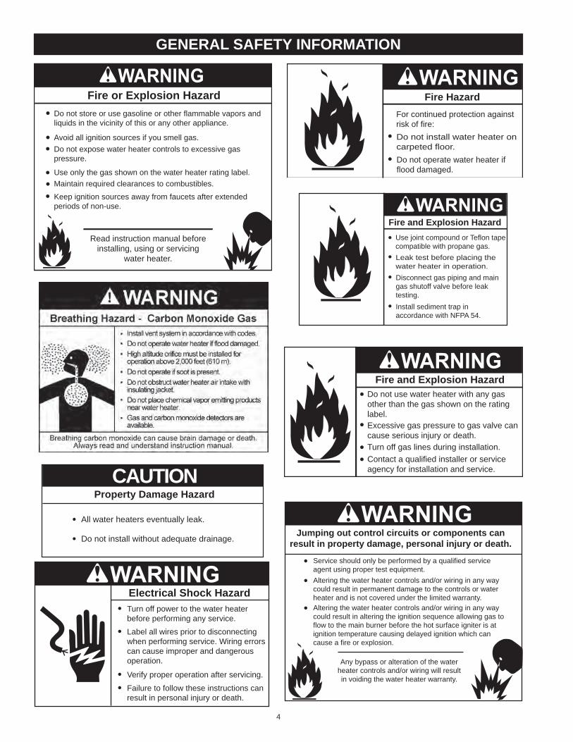
general safety information
Fire Hazard
Do not install water heater oncarpeted floor.Do not operate water heater ifflood damaged.
For continued protection againstrisk of fire:
Fire or Explosion Hazard
Read instruction manual beforeinstalling, using or servicing
water heater.
Avoid all ignition sources if you smell gas.
Do not store or use gasoline or other flammable vapors andliquids in the vicinity of this or any other appliance.
Use only the gas shown on the water heater rating label.
Keep ignition sources away from faucets after extendedperiods of non-use.
Maintain required clearances to combustibles.
Do not expose water heater controls to excessive gaspressure.
Property Damage Hazard
All water heaters eventually leak.•
Do not install without adequate drainage.•
CAUTION
Fire and Explosion Hazard
Leak test before placing thewater heater in operation.Disconnect gas piping and maingas shutoff valve before leaktesting.Install sediment trap inaccordance with NFPA 54.
Use joint compound or Teflon tapecompatible with propane gas.
Fire and Explosion Hazard
Turn off gas lines during installation.Contact a qualified installer or serviceagency for installation and service.
Excessive gas pressure to gas valve cancause serious injury or death.
Do not use water heater with any gasother than the gas shown on the ratinglabel.
Turn off power to the water heaterbefore performing any service.
Electrical Shock Hazard•
Label all wires prior to disconnectingwhen performing service. Wiring errorscan cause improper and dangerousoperation.
•
Verify proper operation after servicing.•Failure to follow these instructions canresult in personal injury or death.
•
Jumping out control circuits or components canresult in property damage, personal injury or death.
Service should only be performed by a qualified serviceagent using proper test equipment.
•Altering the water heater controls and/or wiring in any waycould result in permanent damage to the controls or waterheater and is not covered under the limited warranty.
•
Any bypass or alteration of the waterheater controls and/or wiring will resultin voiding the water heater warranty.
Altering the water heater controls and/or wiring in any waycould result in altering the ignition sequence allowing gas toflow to the main burner before the hot surface igniter is atignition temperature causing delayed ignition which cancause a fire or explosion.
•
5
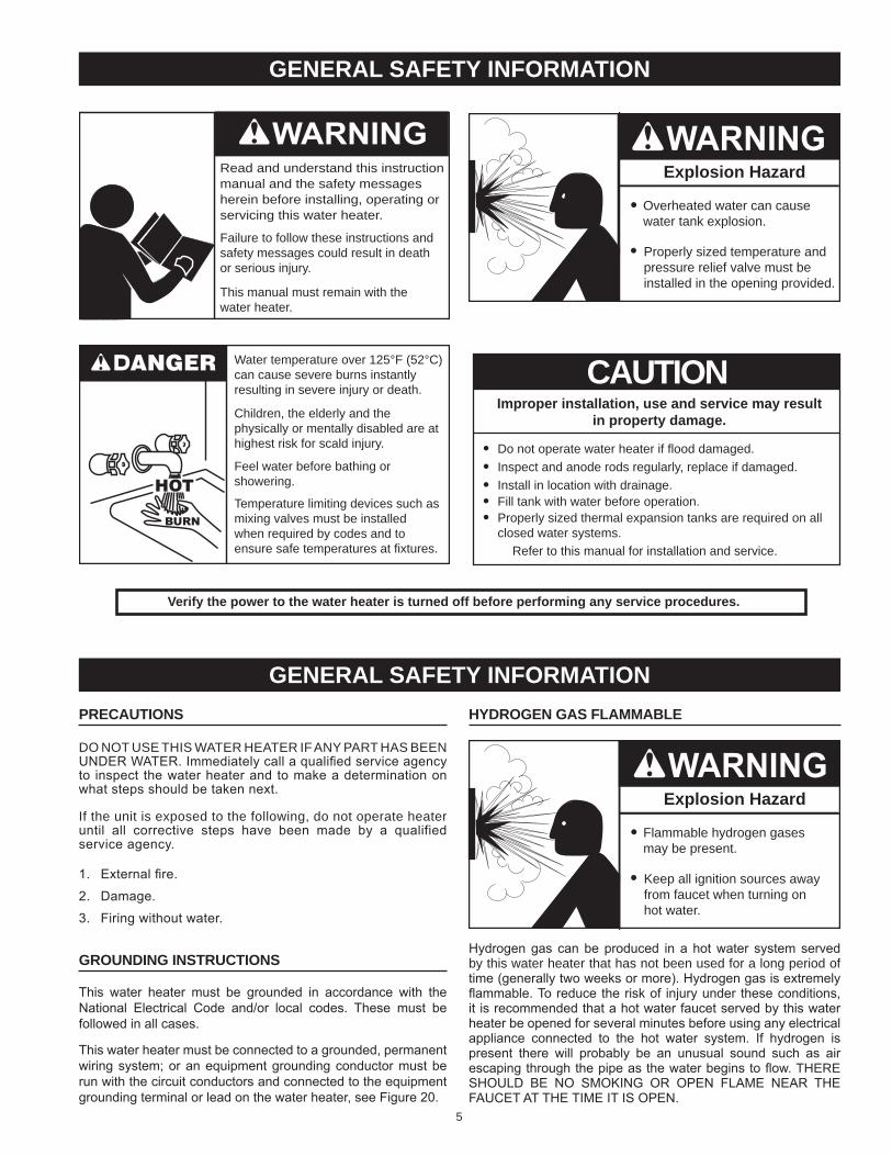
precautions
Do NoT UsE THIs WATER HEATER If ANy PART HAs BEEN UNDeR WATeR. Immediately call a qualified service agency to inspect the water heater and to make a determination on what steps should be taken next.
If the unit is exposed to the following, do not operate heater until all corrective steps have been made by a qualified service agency.
1. external fire.
2. Damage.
3. Firing without water.
grounding instructions
This water heater must be grounded in accordance with the National electrical Code and/or local codes. These must be followed in all cases.
This water heater must be connected to a grounded, permanent wiring system; or an equipment grounding conductor must be run with the circuit conductors and connected to the equipment grounding terminal or lead on the water heater, see Figure 20.
hydrogen gas flammaBle
Explosion Hazard
Flammable hydrogen gasesmay be present.
Keep all ignition sources awayfrom faucet when turning onhot water.
Hydrogen gas can be produced in a hot water system served by this water heater that has not been used for a long period of time (generally two weeks or more). Hydrogen gas is extremely flammable. To reduce the risk of injury under these conditions, it is recommended that a hot water faucet served by this water heater be opened for several minutes before using any electrical appliance connected to the hot water system. If hydrogen is present there will probably be an unusual sound such as air escaping through the pipe as the water begins to flow. THERE SHOULD be NO SMOKING OR OPeN FLAMe NeAR THe FAUCeT AT THe TIMe IT IS OPeN.
general safety information
Verify the power to the water heater is turned off before performing any service procedures.
Read and understand this instructionmanual and the safety messagesherein before installing, operating orservicing this water heater.
Failure to follow these instructions andsafety messages could result in deathor serious injury.
This manual must remain with thewater heater.
Water temperature over 125°F (52°C)can cause severe burns instantlyresulting in severe injury or death.
Children, the elderly and thephysically or mentally disabled are athighest risk for scald injury.
Feel water before bathing orshowering.
Temperature limiting devices such asmixing valves must be installedwhen required by codes and toensure safe temperatures at fixtures.
Explosion Hazard
Overheated water can causewater tank explosion.
Properly sized temperature andpressure relief valve must beinstalled in the opening provided.
Improper installation, use and service may resultin property damage.
Do not operate water heater if flood damaged.•Inspect and anode rods regularly, replace if damaged.•Install in location with drainage.•Fill tank with water before operation.•Properly sized thermal expansion tanks are required on allclosed water systems.
•
Refer to this manual for installation and service.
CAUTION
general safety information
6
introductionThank You for purchasing this water heater. Properly installed and maintained, it should give you years of trouble free service.
aBBreViations used
Abbreviations found in this Instruction Manual include :• ANSI - American National Standards Institute• ASMe - American Society of Mechanical engineers• AHRI - Air-Conditioning, Heating and Refrigeration Institute• NeC - National electrical Code• NFPA - National Fire Protection Association• Ul - Underwriters laboratory• CSA - Canadian Standards Association
Qualifications
Qualified installer or serVice agencyInstallation and service of this water heater requires ability equivalent to that of a Qualified Agency (as defined by ANSI below) in the field involved. Installation skills such as plumbing, air supply, venting, gas supply and electrical supply are required in addition to electrical testing skills when performing service.
ansi Z223.1 2006 sec. 3.3.83: “Qualified Agency” - “Any individual, firm, corporation or company that either in person or through a representative is engaged in and is responsible for (a) the installation, testing or replacement of gas piping or (b) the connection, installation, testing, repair or servicing of appliances and equipment; that is experienced in such work; that is familiar with all precautions required; and that has complied with all the requirements of the authority having jurisdiction.”
If you are not qualified (as defined by ANSI above) and licensed or certified as required by the authority having jurisdiction to perform a given task do not attempt to perform any of the procedures described in this manual. If you do not understand the instructions given in this manual do not attempt to perform any procedures outlined in this manual.
preparing for the installation
1. Read the “General Safety” section, page 4-5 of this manual first and then the entire manual carefully. If you don’t follow
the safety rules, the water heater will not operate properly. It could cause DeATH, SeRIOUS bODILY INJURY AND/OR PROPeRTY DAMAGe.
This manual contains instructions for the installation, operation, and maintenance of the gas-fired water heater. It also contains warnings throughout the manual that you must read and be aware of. All warnings and all instructions are essential to the proper operation of the water heater and your safety. Since we cannot put everything on the first few pages, ReAD THe eNTIRe mANUAl BEfoRE ATTEmPTING To INsTAll oR oPERATE THe WATeR HeATeR.
2. The installation must conform with these instructions and the local code authority having jurisdiction. In the absence of local codes, the installation must comply with the current editions of the National Fuel Gas Code, ANSI Z223.1/NFPA 54 or CAN/CSA-b149.1 the Natural Gas and Propane Installation Code. All documents are available from the Canadian Standards Association, 8501 east Pleasant Valley Road, Cleveland, OH 44131. NFPA documents are also available from the National Fire Protection Association, 1 batterymarch Park, Quincy, MA 02269.
3. If after reading this manual you have any questions or do not understand any portion of the instructions, call the local gas utility or the manufacturer whose name appears on the rating plate.
4. Carefully plan the place where you are going to put the water heater. Correct combustion, vent action, and vent pipe installation are very important in preventing death from possible carbon monoxide poisoning and fires.
examine the location to ensure the water heater complies with the “Locating the New Water Heater” section in this manual.
5. For California installation this water heater must be braced, anchored, or strapped to avoid falling or moving during an earthquake. See instructions for correct installation procedures. Instructions may be obtained from California Office of the State Architect, 400 P Street, Sacramento, CA 95814.
6. Massachusetts Code requires this water heater to be installed in accordance with Massachusetts 248-CMR 2.00: State Plumbing Code and 248-CMR 5.00.
7
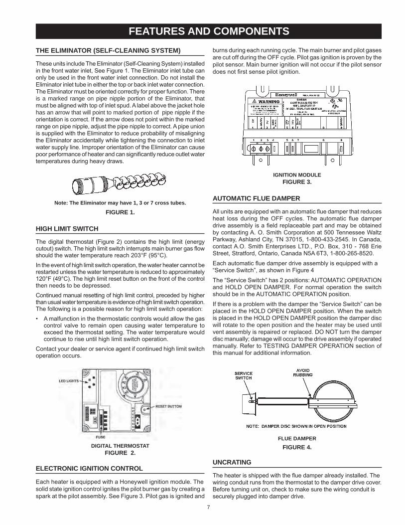
the eliminator (self-cleaning system)
These units include The eliminator (Self-Cleaning System) installed in the front water inlet, See Figure 1. The eliminator inlet tube can only be used in the front water inlet connection. Do not install the eliminator inlet tube in either the top or back inlet water connection. The eliminator must be oriented correctly for proper function. There is a marked range on pipe nipple portion of the Eliminator, that must be aligned with top of inlet spud. A label above the jacket hole has an arrow that will point to marked portion of pipe nipple if the orientation is correct. If the arrow does not point within the marked range on pipe nipple, adjust the pipe nipple to correct. A pipe union is supplied with the eliminator to reduce probability of misaligning the eliminator accidentally while tightening the connection to inlet water supply line. Improper orientation of the eliminator can cause poor performance of heater and can significantly reduce outlet water temperatures during heavy draws.
note: the eliminator may have 1, 3 or 7 cross tubes.
figure 1.
high limit switch
The digital thermostat (Figure 2) contains the high limit (energy cutout) switch. The high limit switch interrupts main burner gas flow should the water temperature reach 203°F (95°C).In the event of high limit switch operation, the water heater cannot be restarted unless the water temperature is reduced to approximately 120°F (49°C). The high limit reset button on the front of the control then needs to be depressed.Continued manual resetting of high limit control, preceded by higher than usual water temperature is evidence of high limit switch operation. The following is a possible reason for high limit switch operation:• A malfunction in the thermostatic controls would allow the gas
control valve to remain open causing water temperature to exceed the thermostat setting. The water temperature would continue to rise until high limit switch operation.
Contact your dealer or service agent if continued high limit switch operation occurs.
digital thermostatfigure 2.
electronic ignition control
each heater is equipped with a Honeywell ignition module. Thesolid state ignition control ignites the pilot burner gas by creating a spark at the pilot assembly. See Figure 3. Pilot gas is ignited and
burns during each running cycle. The main burner and pilot gasesare cut off during the OFF cycle. Pilot gas ignition is proven by thepilot sensor. Main burner ignition will not occur if the pilot sensordoes not first sense pilot ignition.
ignition modulefigure 3.
automatic flue damper
All units are equipped with an automatic flue damper that reduces heat loss during the OFF cycles. The automatic flue damper drive assembly is a field replaceable part and may be obtained by contacting A. O. Smith Corporation at 500 Tennessee Waltz Parkway, Ashland City, TN 37015, 1-800-433-2545. In Canada, contact A.O. Smith enterprises LTD., P.O. box, 310 - 768 erie Street, Stratford, Ontario, Canada N5A 6T3, 1-800-265-8520.
each automatic flue damper drive assembly is equipped with a“Service Switch”, as shown in Figure 4
The “Service Switch” has 2 positions: AUTOMATIC OPeRATION and HOLD OPeN DAMPeR. For normal operation the switch should be in the AUTOMATIC OPeRATION position.
If there is a problem with the damper the “Service Switch” can be placed in the HOLD OPeN DAMPeR position. When the switch is placed in the HOLD OPeN DAMPeR position the damper disc will rotate to the open position and the heater may be used until vent assembly is repaired or replaced. DO NOT turn the damper disc manually; damage will occur to the drive assembly if operated manually. Refer to TeSTING DAMPeR OPeRATION section of this manual for additional information.
flue damperfigure 4.
uncrating
The heater is shipped with the flue damper already installed. Thewiring conduit runs from the thermostat to the damper drive cover.before turning unit on, check to make sure the wiring conduit issecurely plugged into damper drive.
features and components
8
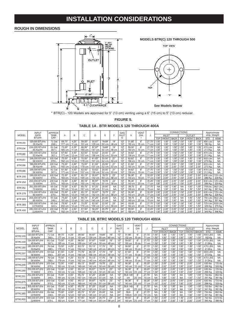
rough in dimensions
installation considerations
taBle 1a . Btr models 120 through 400a
moDElINPUT RATE
bTU/Hr.
APPRoX TANK CAP.
A B C D E fGAs
INlET G
HVeNT DIA
IJ
CoNNECTIoNs Approximate ship. WeightINlET oUTlET
ToP fRoNT bACK ToP fRoNT bACK STD. AsmE
BTR120 120,000 bTU/Hr. 35 Kw/Hr
71 Gal 268 l
69.75” 177 cm
4.25” 11 cm
59.50” 151 cm
50.87” 129 cm
19.69” 50 cm
19” 48 cm
1/2” 1/2”
51.88” 132 cm
6” 15 cm
27.75” 71 cm
1.50” 1.50”
1.50” 1.50”
1.50” 1.50”
1.50” 1.50”
1.50” 1.50”
1.50” 1.50”
400 lbs 182 Kg
NA NA
BTR154 154,000 BTU/Hr 45 Kw/Hr
81 Gal 307 l
73.00” 185 cm
4.25” 11 cm
66.50” 169 cm
57.87” 147 cm
19.69” 50 cm
19”48 cm
1/2” 1/2”
59.00” 150 cm
6”15 cm
27.75” 71 cm
1.50” 1.50”
1.50” 1.50”
1.50” 1.50”
1.50” 1.50”
1.50” 1.50”
1.50” 1.50”
470 lbs 21 3 Kg
NA NA
BTR180 180,000 BTU/Hr 53 Kw/Hr
81Gal 307 l
67.50” 171 cm
4.50” 12 cm
62.00” 157 cm
53.62” 136 cm
20.50” 52 cm
21”53 cm
1/2” 1/2”
54.62” 139 cm
6”15 cm
27.75” 71 cm
1.50” 1.50”
1.50” 1.50”
1.50” 1.50”
1.50” 1.50”
1.50” 1.50”
1.50” 1.50”
470 lbs 21 3 Kg
NA NA
BTR197 199,000 BTU/Hr 58 kW/Hr
100 Gal 379 l
75.00” 192 cm
4.50” 12 cm
70.00” 178 cm
61.62” 157 cm
20.50” 52 cm
21”53 cm
1/2” 1/2”
62.62” 159 cm
6”15 cm
27.75” 71 cm
1.50” 1.50”
1.50” 1.50”
1.50” 1.50”
1.50” 1.50”
1.50” 1.50”
1.50” 1.50”
603 lbs 273 Kg
NA NA
BTR198 199,000 bTU/Hr. 58 Kw/Hr
100 Gal 379 l
75.00” 192 cm
4.50” 12 cm
70.00” 178 cm
61.62” 157 cm
20.50” 52 cm
21”53 cm
1/2” 1/2”
61.50” 150 cm
6”15 cm
27.75” 71 cm
1.50” 1.50”
1.50” 1.50”
2.00” 2.00”
1.50” 1.50”
1.50” 1.50”
2.00” 2.00”
603 lbs 273 Kg
NA NA
BTR199 199,000 BTU/Hr 58 kW/Hr
81 Gal 307 l
67.50” 171 cm
4.50” 12 cm
62.00” 157 cm
53.62” 136 cm
20.50” 52 cm
21”53 cm
1/2” 1/2”
54.62” 139 cm
6”15 cm
27.75” 71 cm
1.50” 1.50”
1.50” 1.50”
1.50” 1.50”
1.50” 1.50”
1.50” 1.50”
1.50” 1.50”
470 lbs 21 3 Kg
NA NA
BTR 200 199,000 BTU/Hr 58 kW/Hr
100 Gal 379 l
72.00” 183 cm
4.50” 12 cm
65.13” 165 cm
55.87” 142 cm
19.75” 50 cm
23”58 cm
1/2” 1/2”
56.38” 143 cm
6”15 cm
30.25” 77 cm
1.50” 1.50”
2.00” 2.00”
2.00” 2.00”
1.50” 1.50”
2.00” 2.00”
2.00” 2.00”
630 lbs 286 Kg
725 lbs 329 Kg
BTR 250 250,000 BTU/Hr 72 kW/Hr
100 Gal 379 l
72.00” 183 cm
4.50” 12 cm
65.13” 165 cm
55.87” 142 cm
19.75” 50 cm
23”58 cm
1/2” 1/2”
56.38” 143 cm
8”20 cm
30.25” 77 cm
1.50” 1.50”
2.00” 2.00”
2.00” 2.00”
1.50” 1.50”
2.00” 2.00”
2.00” 2.00”
630 lbs 286 Kg
725 lbs 329 Kg
BTR 251 251,000 BTU/Hr 73 kW/Hr
65 Gal 246 l
75.00” 191 cm
4.50” 12 cm
65.75” 167 cm
57.25” 145 cm
20.00” 51 cm
NA NA
1/2” 1/2”
58.75 149 cm
8”20 cm
27.75” 70 cm
NA NA
1.50” 1.50”
1.50” 1.50”
NA NA
1.50” 1 .50”
1.50” 1.50”
750lbs 341 Kg
862 lbs 391 Kg
BTR 275 275,000 BTU/Hr 80 kW/Hr
100 Gal 379 l
72.00” 183 cm
4.50” 12 cm
65.13” 165 cm
55.87” 142 cm
19.75” 50 cm
23”58 cm
1/2” 1/2”
56.38” 143 cm
8”20 cm
30.25” 77 cm
1.50” 1.50”
2.00” 2.00”
2.00” 2.00”
1.50” 1.50”
2.00” 2.00”
2.00” 2.00”
630 lbs 286 Kg
725 lbs 329 Kg
BTR 305 305,000 BTU/Hr 89 kW/Hr
65 Gal 246 l
75.00” 191 cm
4.50” 12 cm
65.75” 167 cm
57.25” 145 cm
20.00” 51 cm
NA NA
1/2” 1/2”
58.75 149 cm
8”20 cm
27.75” 70 cm
NA NA
1.50” 1.50”
1.50” 1.50”
NA NA
1.50” 1.50”
1.50” 1.50”
750 lbs 341 Kg
862 lbs 391 Kg
BTR 365 365,000 BTU/Hr 107kW/Hr
85 Gal 322 l
79.50” 202 cm
4.50” 12 cm
70.25” 178 cm
62.50” 159 cm
22.50” 57 cm
23”58 cm
3/4” 3/4”
63.00 160 cm
8”20 cm
27.75” 70 cm
1.50” 1.50”
1.50” 1.50”
1.50” 1.50”
1.50” 1.50”
1.50” 1.50”
1.50” 1.50”
725 lbs 329 Kg
833 lbs 379 Kg
BTR 400 390,000 BTU/Hr 114kW/Hr
100 Gal 379 l
75.50” 192 cm
4.50” 12 cm
67.50” 171 cm
58.25” 148 cm
26.75” 68 cm
23”58 cm
3/4” 3/4”
59.00” 150 cm
8”20 cm
30.25” 77 cm
1.50” 1.50”
2.00” 2.00”
2.00” 2.00”
1.50” 1.50”
2.00” 2.00”
2.00” 2.00”
760 lbs 345 Kg
874 lbs 396 Kg
taBle 1B. Btrc models 120 through 400/a
moDElINPUT RATE
bTU/Hr.
APPROX. TANKCAP.
A B C D E fGAs INlET
GH
VeNT DIA
IJ
CoNNECTIoNs Approximate ship. WeightINlET oUTlET
ToP fRoNT bACK ToP fRoNT bACK STD. AsmE
BTRC120 120,000 bTU/Hr. 35 Kw/Hr
71 Gal 268 l
69.75” 177 cm
4.25” 11 cm
59.50” 151 cm
50.87” 129 cm
19.69” 50 cm
19” 48 cm
1/2” 1/2”
51.88” 132 cm
6” 15 cm
27.75” 71 cm
1.50” 1.50”
1.50” 1.50”
1.50” 1.50”
1.50” 1.50”
1.50” 1.50”
1.50” 1.50”
400 lBs 182 Kg
NA NA
BTRC154 154,000 BTU/Hr 45 Kw/Hr
81 Gal 307 l
73.00” 185 cm
4.25” 11 cm
66.50” 169 cm
57.87” 147 cm
19.69” 50 cm
19”48 cm
1/2” 1/2”
59.00” 150 cm
6” 15 cm
27.75” 71 cm
1.50” 1.50”
1.50” 1.50”
1.50” 1.50”
1.50” 1.50”
1.50” 1 .50”
1.50” 1.50”
470 lBs 213Kq
NA NA
BTRC180 180,000 BTU/Hr 53 Kw/Hr
76 Gal 288 l
70.50” 179 cm
4.25” 11 cm
63.75” 162 cm
55.13” 140 cm
17.75” 45 cm
19”48 cm
1/2” 1/2”
56.50” 144 cm
6” 15 cm
27.75” 71 cm
1.50” 1.50”
1.50” 1.50”
1.50” 1.50”
1.50” 1.50”
1 .50” 1.50”
1.50” 1.50”
470 lBs 213Kq
NA NA
BTRC197 199,000 BTU/Hr 58 kW/Hr
94 Gal 356 l
81.50” 207 cm
4.25” 11 cm
74.75” 190 cm
66.13” 168 cm
17.75” 45 cm
19”48 cm
1/2” 1/2”
67.50” 171 cm
6” 15 cm
27.75” 71 cm
1.50” 1.50”
1.50” 1.50”
1.50” 1.50”
1.50” 1.50”
1.50” 1.50”
1.50” 1.50”
603 lBs 273 Kg
NA NA
BTRC199 199,000 BTU/Hr 58 kW/Hr
76 Gal 288 l
70.50” 179 cm
4.25” 11 cm
63.75” 162 cm
55.13” 140 cm
17.75” 45 cm
19”48 cm
1/2” 1/2”
56.50” 144 cm
6” 15 cm
27.75” 71 cm
1.50” 1.50”
1.50” 1.50”
1.50” 1.50”
1.50” 1.50”
1.50” 1.50”
1.50” 1.50”
470 lBs 213Kq
NA NA
BTRC200 199,000 BTU/Hr 58 kW/Hr
100 Gal 379 l
72.00” 183 cm
4.50” 12 cm
65.13” 165 cm
55.87” 142 cm
19.75” 50 cm
23”58 cm
1/2” 1/2”
56.38” 143 cm
6” 15 cm
30.25” 77 cm
1.50” 1.50”
2.00” 2.00”
2.00” 2.00”
1.50” 1.50”
2.00” 2.00”
2.00” 2.00”
630 Ibs 286 Kg
725 Ibs 329 Kg
BTRC250 250,000 BTU/Hr 72 kW/Hr
100 Gal 379 l
72.00” 183 cm
4.50” 12 cm
65.13” 165 cm
55.87” 142 cm
19.75” 50 cm
23”58 cm
1/2” 1/2”
56.38” 143 cm
8”20 cm
30.25” 77 cm
1.50” 1.50”
2.00” 2.00”
2.00” 2.00”
1.50” 1.50”
2.00” 2.00”
2.00” 2.00”
630 Ibs 286 Kg
725 Ibs 329 Kg
BTRC251 251,000 BTU/Hr 73 kW/Hr
65 Gal 246 l
75.00” 191 cm
4.50” 12 cm
65.75” 167 cm
57.25” 145 cm
20.00” 51 cm
NA NA
1/2” 1/2”
58.8 149 cm
8” 20 cm
27.75” 70 cm
NA NA
1.50” 1.50”
1.50” 1.50”
NA NA
1.50” 1.50”
1.50” 1.50”
750 Ibs 341 Kg
862 Ibs 391 Kg
BTRC275 275,000 BTU/Hr 80 kW/Hr
100 Gal 379 l
72.00” 183 cm
4.50” 12 cm
65.13” 165 cm
55.87” 142 cm
19.75” 50 cm
23”58 cm
1/2” 1/2”
56.38” 143 cm
8”20 cm
30.25” 77 cm
1.50” 1.50”
2.00” 2.00”
2.00” 2.00”
1.50” 1.50”
2.00” 2.00”
2.00” 2.00”
630 Ibs 286 Kg
725 Ibs 329 Kg
BTRC305 305,000 BTU/Hr 89 kW/Hr
65 Gal 246 l
75.00” 191 cm
4.50” 12 cm
65.75” 167 cm
57.25” 145 cm
20.00” 51 cm
NA NA
1/2” 1/2”
58.8 149 cm
8” 20 cm
27.75” 70 cm
NA NA
1 .50” 1 .50”
1.50” 1.50”
NA NA
1.50” 1.50”
1.50” 1.50”
750 Ibs 341 Kg
862 Ibs 391 Kg
BTRC365 365,000 BTU/Hr 107kW/Hr
65 Gal 246 l
75.00” 191 cm
4.50” 12 cm
65.75” 167 cm
57.25” 145 cm
20.00” 51 cm
NA NA
3/4” 3/4”
58.8 149cm
8”20 cm
27.75” 70 cm
NA NA
1 .50” 1.50”
1.50” 1.50”
NA NA
1.50” 1.50”
1.50” 1.50”
750 Ibs 341 Kg
862 Ibs 391 Kg
BTRC400 390,000 BTU/Hr 114kW/Hr
100 Gal 379 l
75.50” 192 cm
4.50” 12 cm
67.50” 171 cm
58.25” 148 cm
26.75” 68 cm
23”58 cm
3/4” 3/4”
59.00” 150 cm
8”20 cm
30.25” 77 cm
1.50” 1.50”
2.00” 2.00”
2.00” 2.00”
1 .50” 1 .50”
2.00” 2.00”
2.00” 2.00”
760 Ibs 345 Kg
874 Ibs 396 Kg
see models Below
figure 5.
models Btr(c) 120 through 500
* bTR(C) - 120 Models are approved for 5” (13 cm) venting using a 6” (15 cm) to 5” (13 cm) reducer.
9
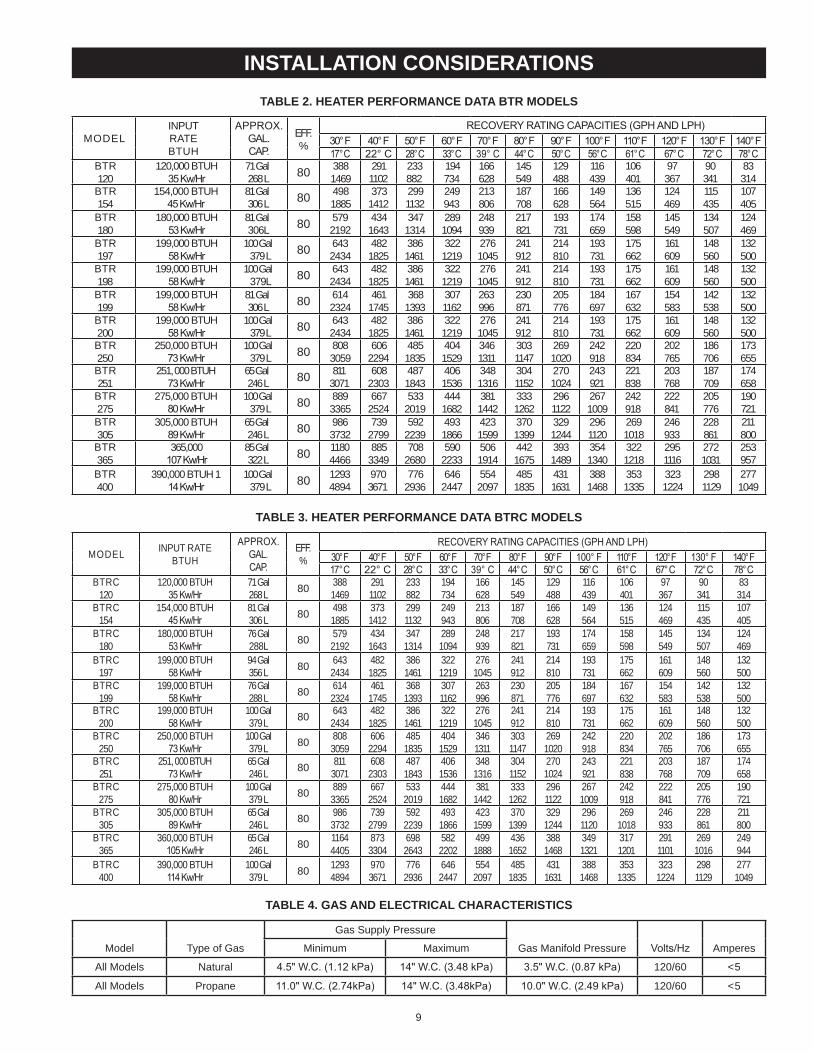
taBle 2. heater performance data Btr models
moDElINPUTRATEBTUH
APPROX. GAL.CAP.
eFF.%
ReCOVeRY RATING CAPACITIeS (GPH AND LPH)30° F 40° F 50° F 60° F 70° F 80° F 90° F 100° F 110° F 120° F 130° F 140° F17° C 22° C 28° C 33° C 39° C 44° C 50° C 56° C 61° C 67° C 72° C 78° C
BTR 120
120,000 BTUH 35 Kw/Hr
71 Gal 268 l 80 388
1469291 1102
233 882
194 734
166 628
145 549
129 488
116 439
106 401
97 367
90 341
83 314
BTR 154
154,000 BTUH 45 Kw/Hr
81 Gal 306 l 80 498
1885373
1412299 1132
249 943
213 806
187 708
166 628
149 564
136 515
124 469
115 435
107 405
BTR 180
180,000 BTUH 53 Kw/Hr
81 Gal 306l 80 579
2192434 1643
347 1314
289 1094
248 939
217 821
193 731
174 659
158 598
145 549
134 507
124 469
BTR 197
199,000 BTUH 58 Kw/Hr
100 Gal 379 l 80 643
2434482 1825
386 1461
322 1219
276 1045
241 912
214 810
193 731
175 662
161 609
148 560
132 500
BTR 198
199,000 BTUH 58 Kw/Hr
100 Gal 379l 80 643
2434482 1825
386 1461
322 1219
276 1045
241 912
214 810
193 731
175 662
161 609
148 560
132 500
BTR 199
199,000 BTUH 58 Kw/Hr
81 Gal 306 l 80 614
2324461
1745368
1393307 1162
263 996
230 871
205 776
184 697
167 632
154 583
142 538
132 500
BTR 200
199,000 BTUH 58 Kw/Hr
100 Gal 379 l 80 643
2434482 1825
386 1461
322 1219
276 1045
241 912
214 810
193 731
175 662
161 609
148 560
132 500
BTR 250
250,000 BTUH 73 Kw/Hr
100 Gal 379 l 80 808
3059606
2294485 1835
404 1529
346 1311
303 1147
269 1020
242 918
220 834
202 765
186 706
173 655
BTR 251
251, 000 BTUH 73 Kw/Hr
65 Gal 246 l 80 811
3071608
2303487 1843
406 1536
348 1316
304 1152
270 1024
243 921
221 838
203 768
187 709
174 658
BTR 275
275,000 BTUH 80 Kw/Hr
100 Gal 379 l 80 889
3365667
2524533
2019444 1682
381 1442
333 1262
296 1122
267 1009
242 918
222 841
205 776
190 721
BTR 305
305,000 BTUH 89 Kw/Hr
65 Gal 246 l 80 986
3732739
2799592
2239493 1866
423 1599
370 1399
329 1244
296 1120
269 1018
246 933
228 861
211 800
BTR 365
365,000 107 Kw/Hr
85 Gal 322 l 80 1180
4466885
3349708
2680590
2233506 1914
442 1675
393 1489
354 1340
322 1218
295 1116
272 1031
253 957
BTR 400
390,000 BTUH 114 Kw/Hr
100 Gal 379 l 80 1293
4894970 3671
776 2936
646 2447
554 2097
485 1835
431 1631
388 1468
353 1335
323 1224
298 1129
277 1049
taBle 3. heater performance data Btrc models
moDEl INPUT RATE BTUH
APPROX. GAL. CAP.
eFF.%
ReCOVeRY RATING CAPACITIeS (GPH AND LPH)30° F 40° F 50° F 60° F 70° F 80° F 90° F 100° F 110° F 120° F 130° F 140° F17° C 22° C 28° C 33° C 39° C 44° C 50° C 56° C 61° C 67° C 72° C 78° C
BTRC 120
120,000 BTUH 35 Kw/Hr
71 Gal 268 l 80 388
1469291 1102
233 882
194 734
166 628
145 549
129 488
116 439
106 401
97 367
90 341
83 314
BTRC 154
154,000 BTUH 45 Kw/Hr
81 Gal 306 l 80 498
1885373 1412
299 1132
249 943
213 806
187 708
166 628
149 564
136 515
124 469
115 435
107 405
BTRC 180
180,000 BTUH 53 Kw/Hr
76 Gal 288l 80 579
2192434 1643
347 1314
289 1094
248 939
217 821
193 731
174 659
158 598
145 549
134 507
124 469
BTRC 197
199,000 BTUH 58 Kw/Hr
94 Gal 356 l 80 643
2434482 1825
386 1461
322 1219
276 1045
241 912
214 810
193 731
175 662
161 609
148 560
132 500
BTRC 199
199,000 BTUH 58 Kw/Hr
76 Gal 288 l 80 614
2324461 1745
368 1393
307 1162
263 996
230 871
205 776
184 697
167 632
154 583
142 538
132 500
BTRC 200
199,000 BTUH 58 Kw/Hr
100 Gal 379 l 80 643
2434482 1825
386 1461
322 1219
276 1045
241 912
214 810
193 731
175 662
161 609
148 560
132 500
BTRC 250
250,000 BTUH 73 Kw/Hr
100 Gal 379 l 80 808
3059606 2294
485 1835
404 1529
346 1311
303 1147
269 1020
242 918
220 834
202 765
186 706
173 655
BTRC 251
251, 000 BTUH 73 Kw/Hr
65 Gal 246 l 80 811
3071608 2303
487 1843
406 1536
348 1316
304 1152
270 1024
243 921
221 838
203 768
187 709
174658
BTRC 275
275,000 BTUH 80 Kw/Hr
100 Gal 379 l 80 889
3365667 2524
533 2019
444 1682
381 1442
333 1262
296 1122
267 1009
242 918
222 841
205 776
190 721
BTRC 305
305,000 BTUH 89 Kw/Hr
65 Gal 246 l 80 986
3732739 2799
592 2239
493 1866
423 1599
370 1399
329 1244
296 1120
269 1018
246 933
228 861
211 800
BTRC 365
360,000 BTUH 105 Kw/Hr
65 Gal 246 l 80 1164
4405873 3304
698 2643
582 2202
499 1888
436 1652
388 1468
349 1321
317 1201
291 1101
269 1016
249 944
BTRC 400
390,000 BTUH 114 Kw/Hr
100 Gal 379 l 80 1293
4894970 3671
776 2936
646 2447
554 2097
485 1835
431 1631
388 1468
353 1335
323 1224
298 1129
277 1049
taBle 4. gas and electrical characteristics
model Type of Gas
Gas supply Pressure
Gas manifold Pressure Volts/Hz Amperesminimum maximum
All models Natural 4.5" W.C. (1.12 kPa) 14" W.C. (3.48 kPa) 3.5" W.C. (0.87 kPa) 120/60 <5
All models Propane 11.0" W.C. (2.74kPa) 14" W.C. (3.48kPa) 10.0" W.C. (2.49 kPa) 120/60 <5
installation considerations
10
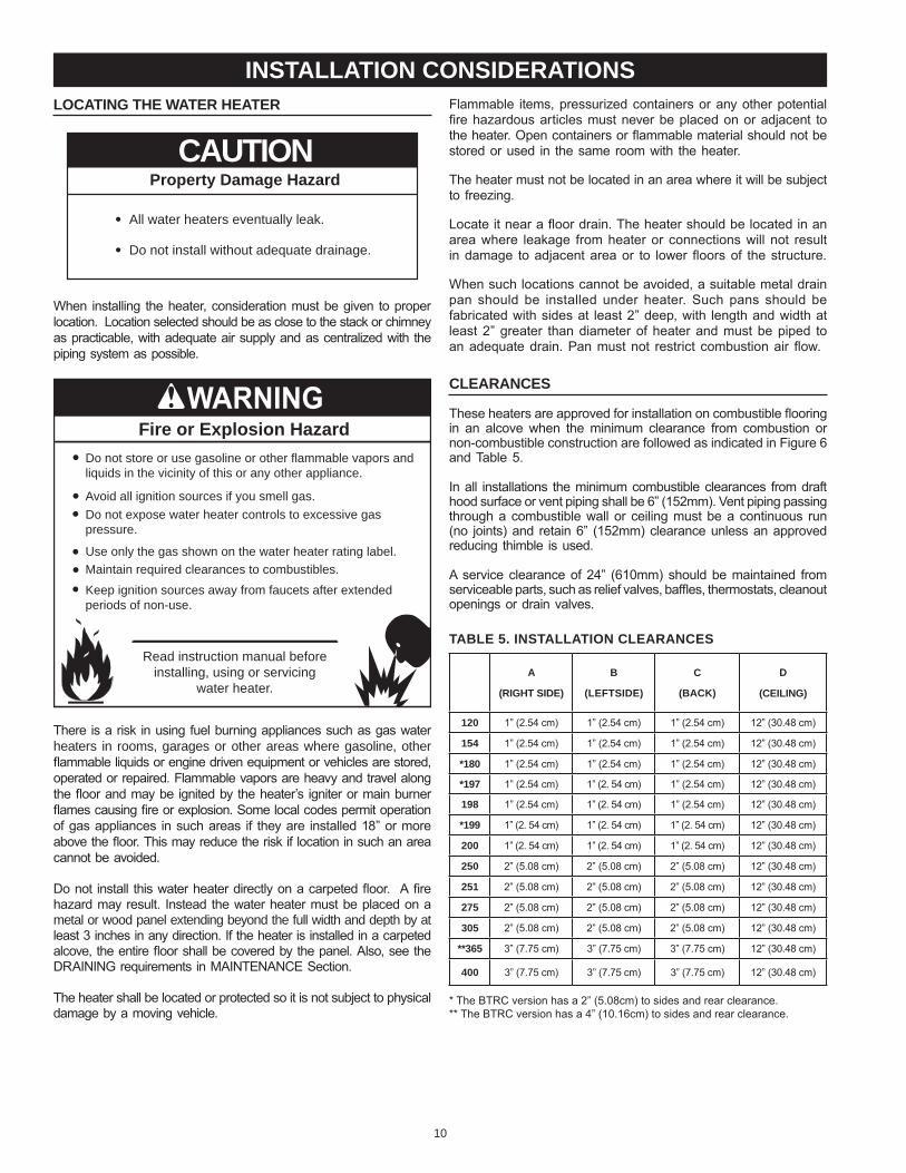
Flammable items, pressurized containers or any other potential fire hazardous articles must never be placed on or adjacent to the heater. Open containers or flammable material should not be stored or used in the same room with the heater.
The heater must not be located in an area where it will be subject to freezing.
Locate it near a floor drain. The heater should be located in an area where leakage from heater or connections will not result in damage to adjacent area or to lower floors of the structure.
When such locations cannot be avoided, a suitable metal drain pan should be installed under heater. Such pans should be fabricated with sides at least 2” deep, with length and width at least 2” greater than diameter of heater and must be piped to an adequate drain. Pan must not restrict combustion air flow.
clearances
These heaters are approved for installation on combustible flooring in an alcove when the minimum clearance from combustion or non-combustible construction are followed as indicated in Figure 6and Table 5.
In all installations the minimum combustible clearances from draft hood surface or vent piping shall be 6” (152mm). Vent piping passing through a combustible wall or ceiling must be a continuous run (no joints) and retain 6” (152mm) clearance unless an approved reducing thimble is used.
A service clearance of 24” (610mm) should be maintained from serviceable parts, such as relief valves, baffles, thermostats, cleanout openings or drain valves.
taBle 5. installation clearances
a
(right side)
B
(leftside)
c
(Back)
d
(ceiling)
120 1” (2.54 cm) 1” (2.54 cm) 1” (2.54 cm) 12” (30.48 cm)
154 1” (2.54 cm) 1” (2.54 cm) 1” (2.54 cm) 12” (30.48 cm)
*180 1” (2.54 cm) 1” (2.54 cm) 1” (2.54 cm) 12” (30.48 cm)
*197 1” (2.54 cm) 1” (2. 54 cm) 1” (2.54 cm) 12” (30.48 cm)
198 1” (2.54 cm) 1” (2. 54 cm) 1” (2.54 cm) 12” (30.48 cm)
*199 1” (2. 54 cm) 1” (2. 54 cm) 1” (2. 54 cm) 12” (30.48 cm)
200 1” (2. 54 cm) 1” (2. 54 cm) 1” (2. 54 cm) 12” (30.48 cm)
250 2” (5.08 cm) 2” (5.08 cm) 2” (5.08 cm) 12” (30.48 cm)
251 2” (5.08 cm) 2” (5.08 cm) 2” (5.08 cm) 12” (30.48 cm)
275 2” (5.08 cm) 2” (5.08 cm) 2” (5.08 cm) 12” (30.48 cm)
305 2” (5.08 cm) 2” (5.08 cm) 2” (5.08 cm) 12” (30.48 cm)
**365 3” (7.75 cm) 3” (7.75 cm) 3” (7.75 cm) 12” (30.48 cm)
400 3” (7.75 cm) 3” (7.75 cm) 3” (7.75 cm) 12” (30.48 cm)
* The bTRC version has a 2” (5.08cm) to sides and rear clearance.** The bTRC version has a 4” (10.16cm) to sides and rear clearance.
locating the water heater
Property Damage Hazard
All water heaters eventually leak.•
Do not install without adequate drainage.•
CAUTION
When installing the heater, consideration must be given to proper location. Location selected should be as close to the stack or chimney as practicable, with adequate air supply and as centralized with the piping system as possible.
Fire or Explosion Hazard
Read instruction manual beforeinstalling, using or servicing
water heater.
Avoid all ignition sources if you smell gas.
Do not store or use gasoline or other flammable vapors andliquids in the vicinity of this or any other appliance.
Use only the gas shown on the water heater rating label.
Keep ignition sources away from faucets after extendedperiods of non-use.
Maintain required clearances to combustibles.
Do not expose water heater controls to excessive gaspressure.
There is a risk in using fuel burning appliances such as gas water heaters in rooms, garages or other areas where gasoline, other flammable liquids or engine driven equipment or vehicles are stored, operated or repaired. Flammable vapors are heavy and travel along the floor and may be ignited by the heater’s igniter or main burner flames causing fire or explosion. Some local codes permit operation of gas appliances in such areas if they are installed 18” or more above the floor. This may reduce the risk if location in such an area cannot be avoided.
Do not install this water heater directly on a carpeted floor. A fire hazard may result. Instead the water heater must be placed on a metal or wood panel extending beyond the full width and depth by at least 3 inches in any direction. If the heater is installed in a carpeted alcove, the entire floor shall be covered by the panel. Also, see the DRAINING requirements in MAINTeNANCe Section.
The heater shall be located or protected so it is not subject to physical damage by a moving vehicle.
installation considerations
11
insulation Blanket
Do not obstruct water heater air intakewith insulating blanket.Gas and carbon monoxide detectorsare available.Install water heater in accordance withthe instruction manual.
Breathing carbon monoxide can cause brain damage ordeath. Always read and understand instruction manual.
Breathing Hazard - Carbon Monoxide Gas
Insulation blankets are available to the general public for external use on gas water heaters but are not necessary with these products. The purpose of an insulation blanket is to reduce the standby heat loss encountered with storage tank heaters. The water heaters covered by this manual meet or exceed the energy Policy Act standards with respect to insulation and standby heat loss requirements, making an insulation blanket unnecessary.Should you choose to apply an insulation blanket to this heater, you should follow these instructions. See the Features and Components section of this manual for identification of components mentioned below. Failure to follow these instructions can restrict the air flow required for proper combustion, potentially resulting in fire, asphyxiation, serious personal injury or death.• do not apply insulation to the top of the water heater, as
this will interfere with safe operation of the draft hood.• do not cover the gas control valve, thermostat or the
Temperature-Pressure Relief Valve.• do not allow insulation to come within 2” (5 cm) of the
burners, to prevent blockage of combustion air flow to the burners.
• do not allow insulation to come within 9 inches (23 cm) of floor, (within 2 inches (5 cm) of bottom cover) to prevent blockage of combustion air flow to the burners..
• do not cover the instruction manual. Keep it on the side of the water heater or nearby for future reference.
• do obtain new warning and instruction labels from the manufacturer for placement on the blanket directly over the existing labels.
• do inspect the insulation blanket frequently to make certain it does not sag, thereby obstructing combustion air flow.
hard water
Where hard water conditions exist, water softening or the threshold type of water treatment is recommended. This will protect the dishwashers, coffee urns, water heaters, water piping and other equipment.See the Maintenance Section in this manual for sediment and lime scale removal procedures.
circulation pumps A circulating pump is used when a system requires a circulating loop or there is a storage tank used in conjunction with the water heater. See Water Piping Diagrams in this manual for installation location of circulating pumps.See the Circulation Pump Wiring Diagrams in this manual for electrical hookup information. Install in accordance with the current edition of the National electrical Code, NFPA 70 or the Canadian electrical Code, CSA C22.1.All-bronze circulating pumps are recommended for used with commercial water heaters.Some circulating pumps are manufactured with sealed bearings and do not require further lubrication. Some circulating pumps
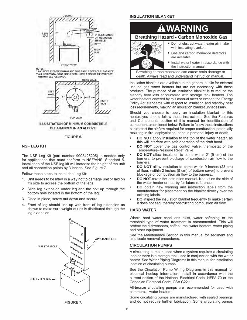
figure 6.
nsf leg kit
The NSF Leg Kit (part number 9003425205) is needed only for applications that must conform to NSF/ANSI Standard 5. Installation of the NSF leg kit will increase the height of the unit and all connection points by 3 inches. See Figure 7. Follow these steps to install the Leg Kit:1. Unit needs to be lifted in a way not to damage unit or laid on
it’s side to access the bottom of the legs.2. Slide leg extension under leg and the bolt up through the
bottom hole located in the bottom of the leg.3. Once in place, screw nut down and secure.4. Front of leg should line up with front of leg extension as
shown to make sure weight of unit is distributed through the leg extension.
figure 7.
12
Breathing Hazard - Carbon Monoxide Gas
Breathing carbon monoxide can cause brain damage ordeath. Always read and understand instruction manual.
Under no circumstances shouldthe input exceed the rate shownon the water heater’s rating label.
Overfiring could result in damage tothe water heater and sooting.
Gas and carbon monoxide detectorsare available.
Installations above 2000 feet (610 meters) require replacement of burner orifices in accordance with current edition of the National fuel Gas Code (ANsI z223.1). For Canadian installations consult Canadian Installations Code CAN/CsA B149.1. Failure to replace orifices will result in improper and inefficient operation of the water heater resulting in the production of increased levels of carbon monoxide gas in excess of safe limits which could result in serious personal injury or death.
You should contact your gas supplier for any specific changes which may be required in your area.
As the elevation above sea level is increased, there is less oxygen per cubic foot of air. Therefore, the heater input rate should be reduced at high altitudes for satisfactory operation with the reduced oxygen supply. Failure to make this reduction would result in an over firing of the heater causing sooting, poor combustion and/or unsatisfactory heater performance.
Ratings specified by manufacturers for most appliances apply for elevations up to 2000 feet (610m). For elevations above 2000 feet (610), ratings must be reduced at the rate of 4% for each 1000 feet (305m) above sea level. For example, if a heater is rated at 78,000 btuh (22.9 Kwh) at sea level, to rate the heater at 4000 feet (1219m), you subtract 4 (once for each thousand feet) x.04 (4% input reduction) x 78,000 (original rating) from the original rating.
Therefore, to calculate the input rating at 4,000 feet (1219m): 4 x .04 x 78,000 = 12,480 btuh (3.7 Kwh), 78,000 (22.9 Kwh) - 12,480 (3.7 Kwh) = 65,520 btuh (19.2 Kwh). At 6000 feet (1829m) the correct input rating should be 59,280 btuh (17.4 Kwh).
must be periodically oiled. Refer to the pump manufacturer’s instructions for lubrication requirements.
CIRCULATING PUMP WIRING DIAGRAMSTORAGE TANK OR BUILDING RECIRCULATION
FIELD SUPPLIED TEMPERATURE CONTROLINSTALLED IN THE STORAGE TANKOR CIRCULATING LOOP RETURN LINE
CIRCPUMP
MOTOR
L1 HOT
L2 NEUTRAL
120 VACPOWER
CIRCULATING PUMP WIRING DIAGRAMDISHWASHER LOOP WITH TOGGLE SWITCH
FIELD SUPPLIED TEMPERATURECONTROL INSTALLED IN THECIRCULATING LOOP RETURN LINE
DISHWASHERTOGGLESWITCH
CIRCPUMP
MOTOR
L1 HOT
L2 NEUTRAL
120 VACPOWER
NOTE: USE SEPARATE 120 VAC POWERSUPPLY FOR PUMP CIRCUIT. DO NOTSHARE POWER WITH WATER HEATER AS THISMAY CAUSE ELECTRICAL LINE NOISE ANDLEAD TO ERRATIC CONTROL SYSTEMOPERATION.
NOTE: USE SEPARATE 120 VAC POWERSUPPLY FOR PUMP CIRCUIT. DO NOT SHARE POWER WITH WATER HEATER AS THIS MAY CAUSE ELECTRICAL LINE NOISE AND LEAD TO ERRATIC CONTROL SYSTEM OPERATION.
figure 8.
CIRCULATING PUMP WIRING DIAGRAMSTORAGE TANK OR BUILDING RECIRCULATION
FIELD SUPPLIED TEMPERATURE CONTROLINSTALLED IN THE STORAGE TANKOR CIRCULATING LOOP RETURN LINE
CIRCPUMP
MOTOR
L1 HOT
L2 NEUTRAL
120 VACPOWER
CIRCULATING PUMP WIRING DIAGRAMDISHWASHER LOOP WITH TOGGLE SWITCH
FIELD SUPPLIED TEMPERATURECONTROL INSTALLED IN THECIRCULATING LOOP RETURN LINE
DISHWASHERTOGGLESWITCH
CIRCPUMP
MOTOR
L1 HOT
L2 NEUTRAL
120 VACPOWER
NOTE: USE SEPARATE 120 VAC POWERSUPPLY FOR PUMP CIRCUIT. DO NOTSHARE POWER WITH WATER HEATER AS THISMAY CAUSE ELECTRICAL LINE NOISE ANDLEAD TO ERRATIC CONTROL SYSTEMOPERATION.
NOTE: USE SEPARATE 120 VAC POWERSUPPLY FOR PUMP CIRCUIT. DO NOT SHARE POWER WITH WATER HEATER AS THIS MAY CAUSE ELECTRICAL LINE NOISE AND LEAD TO ERRATIC CONTROL SYSTEM OPERATION.
figure 9.
high altitude installations
Fire and Explosion Hazard
Gas and carbon monoxide detectors areavailable.
Overfiring could result in fire orexplosion.
Under no circumstances should the input exceed the rate shown on the water heater’s rating label.
13
4. When installing multiple water heaters in the same gas supply system it is recommended that individual positive lock-up gas pressure regulators be installed at each unit.
power supplyThe water heaters covered in this manual require a 120 VAC, 1Ø (single phase), 60Hz, 15 amp power supply and must also be electrically grounded in accordance with local codes or, in the absence of local codes, with the National electrical Code, ANSI/NFPA 70 or the Canadian electrical Code, CSA C22.1.
water temperature control and mixing ValVes
Water temperature over 125°F (52°C)can cause severe burns instantlyresulting in severe injury or death.
Children, the elderly and thephysically or mentally disabled are athighest risk for scald injury.
Feel water before bathing or showering.Temperature limiting devices such asmixing valves must be installedwhen required by codes and toensure safe temperatures at fixtures.
Water heated to a temperature which will satisfy clothes washing, dish washing, and other sanitizing needs can scald and cause permanent injury upon contact. Short repeated heating cycles caused by small hot water uses can cause temperatures at the point of use to exceed the water heater’s temperature setting by up to 20°F (11°C).
some people are more likely to be permanently injured by hot water than others. These include the elderly, children, the infirm and the physically/mentally disabled. Table 6 shows approximate time-to-burn relationship for normal adult skin. If anyone using hot water provided by the water heater being installed fits into one of these groups or if there is a local code or state law requiring a certain water temperature at the point of use, then special precautions must be taken.
In addition to using the lowest possible temperature setting that satisfies the demand of the application a Mixing Valve should be installed at the water heater (see figure 10) or at the hot water taps to further reduce system water temperature.
Mixing valves are available at plumbing supply stores. Consult a Qualified Installer or Service Agency. Follow mixing valve manufacturer’s instructions for installation of the valves.
taBle 6.
Water Temperature °F Time for 1st Degree Burn(Less Severe burns)
Time for Permanent Burns2nd & 3rd Degree
(Most Severe burns)110 (normal shower temp.)116 (pain threshold)116 35 minutes 45 minutes122 1 minute 5 minutes131 5 seconds 25 seconds140 2 seconds 5 seconds149 1 second 2 seconds154 instantaneous 1 second
(U.S. Government Memorandum, C.P.S.C., Peter L. Armstrong, Sept. 15,1978)
gas supply systemslow pressure building gas supply systems are defined as those systems that cannot under any circumstances exceed 14” W.C. (1/2 PSI Gauge). These systems do not require pressure regulation. Measurements should be taken to insure that gas pressures are stable and fall within the requirements stated on the water heater rating plate. Readings should be taken with all gas burning equipment off (static pressure) and with all gas burning equipment running at maximum rate (dynamic pressure). The gas supply pressure must be stable within 1.5” W.C. from static to dynamic pressure to provide good performance. Pressure drops that exceed 1.5” W.C. may cause rough starting, noisy combustion or nuisance outages. Increases or spikes in static pressure during off cycles may cause failure to ignite or in severe cases damage to appliance gas valves. If your low pressure system does NoT meet these requirements, the installer is responsible for the corrections.
High Pressure building supply systems use pressures that exceed 14” W.C. (1/2 PSI Gauge). These systems must use field supplied regulators to lower the gas pressure to less than 14” W.C. (1/2 PSI Gauge). Water heaters require gas regulators that are properly sized for the water heater input and deliver the rating plate specified pressures. Gas supply systems where pressure exceeds 5 PSI often require multiple regulators to achieve desired pressures. Systems in excess of 5 PSI building pressure should be designed by gas delivery professionals for best performance. Water heaters connected to gas supply systems that exceed 14” W.C. (1/2 PSI Gauge) at any time must be equipped with a gas supply regulator.
All models require a minimum gas supply pressure of 4.5" W.C. for natural gas and 11.0" W.C. for propane gas. The minimum supply pressure is measured while gas is flowing (dynamic pressure). The supply pressure should never fall below 4.5" W.C. for natural gas and 11.0" W.C. for propane gas. The supply pressure should be measured with all gas fired appliances connected to the common main firing at full capacity. If the supply pressure drops more than 1.5” W.C. as gas begins to flow to the water heater then the supply gas system including the gas line and/or the gas regulator may be restricted or undersized. See Supply Gas Regulator section and Gas Piping section of this manual. The gas valve on all models has a maximum gas supply pressure limit of 14” W.C. The maximum supply pressure is measured while gas is not flowing (static pressure).
supply gas regulatorThe maximum allowable gas supply pressure for this water heater is 14 inches W.C. (3.48 kPa). Install a positive lock-up gas pressure regulator in the gas supply line if inlet gas pressure can exceed 14 inches W.C. (3.48 kPa) at any time. Regulators must be sized/used according to manufacturer’s specifications.If a positive lock-up regulator is required follow these instructions:1. Positive lock-up gas pressure regulators must be rated at or above the input btu/hr rating of the water heater they supply.2. Positive lock-up gas pressure regulator(s) should be installed no closer than 3 equivalent feet (1 meter) and no farther than 8 equivalent feet (2.4 meters) from water heater’s inlet gas connection.3. After installing the positive lock-up gas pressure regulator(s) an initial nominal supply pressure setting of 7.0” W.C. while the water heater is operating is recommended and will generally provide good water heater operation. Some addition adjustment maybe required later to maintain a steady gas supply pressure.
installation reQuirements
14
HOT WATEROUTLET
TO TANKINLET
CHECKVALVE
MIXINGVALVE
COLDWATERINLET
TEMPERED WATEROUTLET
12” TO 15”(30-38 cm)
CHECKVALVE
figure 10.
dishwashing machines
All dishwashing machines meeting the National Sanitation Foundation requirements are designed to operate with water flow pressures between 15 and 25 pounds per square inch (103 kPa and 173 kPa). Flow pressures above 25 pounds per square inch (173 kPa), or below 15 pounds per square inch (103 kPa), will result in improperly sanitized dishes. Where pressures are high, a water pressure reducing or flow regulating control valve should be used in the 180°F (82°C) line to the dishwashing machine and should be adjusted to deliver water pressure between these limits.The National Sanitation Foundation also recommends circulation of 180°F (82°C) water. The circulation flow rate should be just enough to provide 180°F (82°C) water at the point of take-off to the dishwashing machine. Adjust flow by throttling a full port ball valve installed in the circulating line on the outlet side of the pump. Never throttle flow on the suction side of a pump. See Water Piping Diagrams in this manual.note: These water heaters meet the Nsf standard 5 for sanitary installations when used with the leg kit part number 9003425205.
closed water systems
Water supply systems may, because of code requirements or such conditions as high line pressure, among others, have installed devices such as pressure reducing valves, check valves, and back flow preventers. Devices such as these cause the water system to be a closed system.
thermal expansion
As water is heated, it expands (thermal expansion). In a closed system the volume of water will grow when it is heated. As the volume of water grows there will be a corresponding increase in water pressure due to thermal expansion. Thermal expansion can cause premature tank failure (leakage). This type of failure is not covered under the limited warranty. Thermal expansion can also cause intermittent Temperature-Pressure Relief Valve operation: water discharged from the valve due to excessive pressure build up. This condition is not covered under the limited warranty. The Temperature-Pressure Relief Valve is not intended for the constant relief of thermal expansion.
A properly sized thermal expansion tank must be installed on all closed systems to control the harmful effects of thermal expansion. Contact a local plumbing service agency to have a thermal expansion tank installed.See Water Line Connections on page 21 and the Water Piping Diagrams beginning on page 40.
temperature-pressure relief ValVe
Explosion Hazard
Temperature-Pressure Relief Valvemust comply with ANSI Z21.22-CSA 4.4 and ASME code.
Properly sized temperature-pressure relief valve must beinstalled in opening provided.
Can result in overheating andexcessive tank pressure.
Can cause serious injury or death.
This water heater is provided with a properly rated/sized and certified combination Temperature-Pressure Relief Valve (T&P valve) by the manufacturer. The valve is certified by a nationally recognized testing laboratory that maintains periodic inspection of production of listed equipment of materials as meeting the requirements for Pressure Relief Valves for Hot Water Supply Systems, ANSI Z21.22 • CSA 4.4, and the code requirements of ASMe.If replaced, the new T&P valve must meet the requirements of local codes, but not less than a combination Temperature-Pressure Relief Valve rated/sized and certified as indicated in the above paragraph. The new valve must be marked with a maximum set pressure not to exceed the marked hydrostatic working pressure of the water heater (150 psi = 1,035 kPa) and a discharge capacity not less than the water heater btu/hr or kW input rate as shown on the water heater’s model rating label.NOTe: In addition to the factory installed Temperature-Pressure Relief Valve on the water heater, each remote storage tank that may be installed and piped to a water heating appliance must also have its own properly sized, rated and approved Temperature-Pressure Relief Valve installed. Call the toll free technical support phone number listed on the back cover of this manual for technical assistance in sizing a Temperature-Pressure Relief Valve for remote storage tanks.for safe operation of the water heater, the Temperature-Pressure Relief Valve must not be removed from its designated opening nor plugged. The Temperature-Pressure Relief Valve must be installed directly into the fitting of the water heater designed for the pressure relief valve . Install discharge piping so that any discharge will exit the pipe within 6 inches (15.2 cm) above an adequate floor drain, or external to the building. In cold climates it is recommended that it be terminated at an adequate drain inside the building. be certain that no contact is made with any live electrical part. The discharge opening must not be blocked or reduced in size under any circumstances. excessive length, over 30 feet (9.14 m), or use of more than four elbows can cause restriction and reduce the discharge capacity of the valve.
15
No valve or other obstruction is to be placed between the Temperature-Pressure Relief Valve and the tank. Do not connect discharge piping directly to the drain unless a 6” (15.2 cm) air gap is provided. To prevent bodily injury, hazard to life, or property damage, the relief valve must be allowed to discharge water in adequate quantities should circumstances demand. If the discharge pipe is not connected to a drain or other suitable means, the water flow may cause property damage.
Water Damage Hazard
Temperature-Pressure Relief Valve dischargepipe must terminate at adequate drain.
•
CAUTION
t&p Valve discharge pipe requirements:• shall not be smaller in size than the outlet pipe size of the
valve, or have any reducing couplings or other restrictions.• Shall not be plugged or blocked.• Shall not be exposed to freezing temperatures.• Shall be of material listed for hot water distribution.• Shall be installed so as to allow complete drainage of both
the Temperature-Pressure Relief Valve and the discharge pipe.
• Must terminate a maximum of six inches above a floor drain or external to the building. In cold climates, it is recommended that the discharge pipe be terminated at an adequate drain inside the building.
• Shall not have any valve or other obstruction between the pressure relief valve and the drain.
Burn hazard.
Hot water discharge.
Keep clear of Temperature-Pressure Relief Valvedischarge outlet.
The Temperature-Pressure Relief Valve must be manually operated at least twice a year. Caution should be taken to ensure that (1) no one is in front of or around the outlet of the Temperature-Pressure Relief Valve discharge line, and (2) the water manually discharged will not cause any bodily injury or property damage because the water may be extremely hot. If after manually operating the valve, it fails to completely reset and continues to release water, immediately close the cold water inlet to the water heater, follow the draining instructions in this manual, and replace the Temperature-Pressure Relief Valve with a properly rated/sized new one.note: The purpose of a Temperature-Pressure Relief Valve is to prevent excessive temperatures and pressures in the storage tank. The T&P valve is not intended for the constant relief of thermal expansion. A properly sized thermal expansion tank must be installed on all closed systems to control thermal expansion, see Closed Water Systems and Thermal expansion on page 14.If you do not understand these instructions or have any questions regarding the Temperature-Pressure Relief Valve call the toll free number listed on the back cover of this manual for technical assistance.
contaminated air
Breathing Hazard - Carbon Monoxide GasInstall water heater in accordance withthe Instruction Manual and NFPA 54 orCAN/CSA-B149.1.To avoid injury, combustion and ventilationair must be taken from outdoors.Do not place chemical vapor emittingproducts near water heater.
Breathing carbon monoxide can cause brain damage ordeath. Always read and understand instruction manual.
Corrosion of the flue ways and vent system may occur if air for combustion contains certain chemical vapors. Such corrosion may result in failure and risk of asphyxiation.Combustion air that is contaminated can greatly diminish the life span of the water heater and water heater components such as hot surface igniters and burners. Propellants of aerosol sprays, beauty shop supplies, water softener chemicals and chemicals used in dry cleaning processes that are present in the combustion, ventilation or ambient air can cause such damage.Do not store products of this sort near the water heater. Air which is brought in contact with the water heater should not contain any of these chemicals. If necessary, uncontaminated air should be obtained from remote or outdoor sources. The limited warranty is voided when failure of water heater is due to a corrosive atmosphere. (See limited warranty for complete terms and conditions).
air reQuirements
Breathing Hazard - Carbon Monoxide GasInstall water heater in accordance withthe Instruction Manual and NFPA 54 orCAN/CSA-B149.1.To avoid injury, combustion and ventilationair must be taken from outdoors.Do not place chemical vapor emittingproducts near water heater.
Breathing carbon monoxide can cause brain damage ordeath. Always read and understand instruction manual.
For safe operation an adequate supply of fresh uncontaminated air for combustion and ventilation must be provided.An insufficient supply of air can cause recirculation of combustion products resulting in contamination that may be hazardous to life. Such a condition often will result in a yellow, luminous burner flame, causing sooting of the combustion chamber, burners and flue tubes and creates a risk of asphyxiation.Do not install the water heater in a confined space unless an adequate supply of air for combustion and ventilation is brought in to that space using the methods described in the Confined Space section that follows.Never obstruct the flow of ventilation air. If you have any doubts or questions at all, call your gas supplier. Failure to provide the proper amount of combustion air can result in a fire or explosion and cause property damage, serious bodily injury or death.
16
direct Vent appliancesAppliances installed in a Direct Vent configuration that derive all air for combustion from the outdoor atmosphere through sealed intake air piping are not factored in the total appliance input btu/hr calculations used to determine the size of openings providing fresh air into confined spaces.exhaust fansWhere exhaust fans are installed, additional air shall be provided to replace the exhausted air. When an exhaust fan is installed in the same space with a water heater, sufficient openings to provide fresh air must be provided that accommodate the requirements for all appliances in the room and the exhaust fan. Undersized openings will cause air to be drawn into the room through the water heater’s vent system causing poor combustion. Sooting, serious damage to the water heater and the risk of fire or explosion may result. It can also create a risk of asphyxiation.louVers and grillesThe free areas of the fresh air openings in the instructions that follow do not take in to account the presence of louvers, grilles or screens in the openings.The required size of openings for combustion, ventilation and dilution air shall be based on the “net free area” of each opening. Where the free area through a design of louver or grille or screen is known, it shall be used in calculating the size of opening required to provide the free area specified. Where the louver and grille design and free area are not known, it shall be assumed that wood louvers will have 25% free area and metal louvers and grilles will have 75% free area. Non motorized louvers and grilles shall be fixed in the open position.
unconfined space
An Unconfined Space is one whose volume IS NOT LeSS THAN 50 cubic feet per 1,000 btu/hr (4.8 cubic meters per kW) of the total input rating of all appliances installed in the space. Rooms communicating directly with the space, in which the appliances are installed, through openings not furnished with doors, are considered a part of the unconfined space.makeup air requirements for the operation of exhaust fans, kitchen ventilation systems, clothes dryers and fireplaces shall also be considered in determining the adequacy of a space to provide combustion, ventilation and dilution air.
unusually tight constructionIn unconfined spaces in buildings, infiltration may be adequate to provide air for combustion, ventilation and dilution of flue gases. However, in buildings of unusually tight construction (for example, weather stripping, heavily insulated, caulked, vapor barrier, etc.) additional air must be provided using the methods described in the Confined Space section that follows.
confined space
A Confined Space is one whose volume is less than 50 cubic feet per 1,000 btu/hr (4.8 cubic meters per kW) of the total input rating of all appliances installed in the space.Openings must be installed to provide fresh air for combustion, ventilation and dilution in confined spaces. The required size for the openings is dependent on the method used to provide fresh air to the confined space and the total btu/hr input rating of all appliances installed in the space.
Venting installationVenting
THe INSTRUCTIONS IN THIS SeCTION ON VeNTING MUST be FOLLOWeD TO AVOID CHOKeD COMbUSTION OR ReCIRCULATION OF FLUe GASeS. SUCH CONDITIONS CAUSe SOOTING OR RISKS OF FIRe AND ASPHYXIATION.Heater must be protected from freezing downdrafts.Remove all soot or other obstructions from the chimney that will retard a free draft.Type b venting is recommended with these heaters. For typical venting application see TeCHNICAL DATA VeNTING on pages 19 and 20. This water heater must be vented in compliance with all local codes, the current revision of the National Fuel Gas Code (ANSI-Z223.1) and with the Category I Venting Tables.If any part of the vent system are exposed to ambient temperatures below 40°F it must be insulated to prevent condensation.• Do not connect the heater to a common vent or chimney with solid
fuel burning equipment. This practice is prohibited by many local building codes as is the practice of venting gas fired equipment to the duct work of ventilation systems.
• Where a separate vent connection is not available and the vent pipe from the heater must be connected to a common vent with an oil burning furnace, the vent pipe should enter the smaller common vent or chimney at a point above the large vent pipe.
Vent reducer
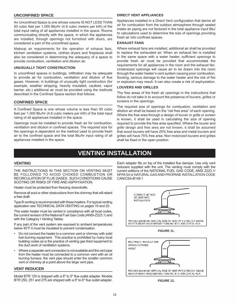
Model bTR 120 is shipped with a 6" to 5" flue outlet adapter. Models bTR 250, 251 and 275 are shipped with a 8" to 6" flue outlet adapter.
each adapter fits on top of the installed flue damper. Use only vent reducers supplied with the unit. The venting must comply with the current editions of the NATIONAL FUeL GAS CODe, ANSI Z223.1/NfPA 54 or NATURAl GAs AND PRoPANE INsTAllATIoN CoDECAN/CSA-b149.1
figure 11.
figure 12.
17
multiple heater manifold
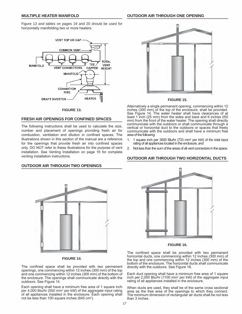
figure 13 and tables on pages 19 and 20 should be used for horizontally manifolding two or more heaters.
figure 13.
fresh air openings for confined spaces
The following instructions shall be used to calculate the size, number and placement of openings providing fresh air for combustion, ventilation and dilution in confined spaces. The illustrations shown in this section of the manual are a reference for the openings that provide fresh air into confined spaces only. DO NOT refer to these illustrations for the purpose of vent installation. See Venting Installation on page 16 for complete venting installation instructions.
outdoor air through two openings
figure 14.
The confined space shall be provided with two permanent openings, one commencing within 12 inches (300 mm) of the top and one commencing within 12 inches (300 mm) of the bottom of the enclosure. The openings shall communicate directly with the outdoors. See Figure 14.each opening shall have a minimum free area of 1 square inch per 4,000 Btu/hr (550 mm2 per kW) of the aggregate input rating of all appliances installed in the enclosure. each opening shall not be less than 100 square inches (645 cm2).
outdoor air through one opening
figure 15.
Alternatively a single permanent opening, commencing within 12 inches (300 mm) of the top of the enclosure, shall be provided. See Figure 14. The water heater shall have clearances of at least 1 inch (25 mm) from the sides and back and 6 inches (l50 mm) from the front of the water heater. The opening shall directly communicate with the outdoors or shall communicate through a vertical or horizontal duct to the outdoors or spaces that freely communicate with the outdoors and shall have a minimum free area of the following:1. 1 square inch per 3000 btu/hr (733 mm2 per kW) of the total input
rating of all appliances located in the enclosure, and2. Not less than the sum of the areas of all vent connectors in the space.
outdoor air through two horiZontal ducts
figure 16.
The confined space shall be provided with two permanent horizontal ducts, one commencing within 12 inches (300 mm) of the top and one commencing within 12 inches (300 mm) of the bottom of the enclosure. The horizontal ducts shall communicate directly with the outdoors. See Figure 16.
each duct opening shall have a minimum free area of 1 square inch per 2,000 btu/hr (1100 mm2 per kW) of the aggregate input rating of all appliances installed in the enclosure.
When ducts are used, they shall be of the same cross sectional area as the free area of the openings to which they connect. The minimum dimension of rectangular air ducts shall be not less than 3 inches.
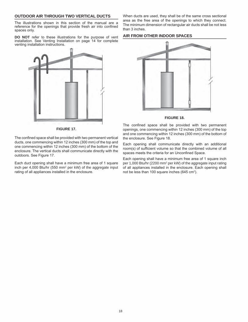
18
When ducts are used, they shall be of the same cross sectional area as the free area of the openings to which they connect. The minimum dimension of rectangular air ducts shall be not less than 3 inches.
air from other indoor spaces
figure 18.
The confined space shall be provided with two permanent openings, one commencing within 12 inches (300 mm) of the top and one commencing within 12 inches (300 mm) of the bottom of the enclosure. See Figure 18.each opening shall communicate directly with an additional room(s) of sufficient volume so that the combined volume of all spaces meets the criteria for an Unconfined Space.each opening shall have a minimum free area of 1 square inch per 1,000 Btu/hr (2200 mm2 per kW) of the aggregate input rating of all appliances installed in the enclosure. each opening shall not be less than 100 square inches (645 cm2).
outdoor air through two Vertical ductsThe illustrations shown in this section of the manual are a reference for the openings that provide fresh air into confined spaces only.
do not refer to these illustrations for the purpose of vent installation. See Venting Installation on page 14 for complete venting installation instructions.
figure 17.
The confined space shall be provided with two permanent vertical ducts, one commencing within 12 inches (300 mm) of the top and one commencing within 12 inches (300 mm) of the bottom of the enclosure. The vertical ducts shall communicate directly with the outdoors. See Figure 17.
each duct opening shall have a minimum free area of 1 square inch per 4,000 btu/hr (550 mm2 per kW) of the aggregate input rating of all appliances installed in the enclosure.
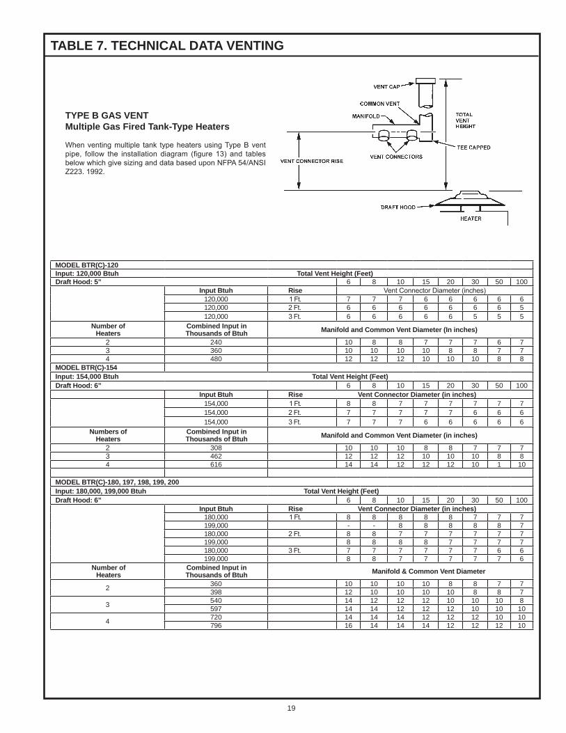
19
type B gas Ventmultiple gas fired tank-type heaters
When venting multiple tank type heaters using Type b vent pipe, follow the installation diagram (figure 13) and tables below which give sizing and data based upon NFPA 54/ANSI Z223. 1992.
taBle 7. technical data Venting
model Btr(c)-120input: 120,000 Btuh total Vent height (feet)draft hood: 5” 6 8 10 15 20 30 50 100
input Btuh rise Vent Connector Diameter (inches)120,000 1 Ft. 7 7 7 6 6 6 6 6120,000 2 Ft. 6 6 6 6 6 6 6 5120,000 3 Ft. 6 6 6 6 6 5 5 5
number of heaters
combined input in thousands of Btuh manifold and common Vent diameter (in inches)
2 240 10 8 8 7 7 7 6 73 360 10 10 10 10 8 8 7 74 480 12 12 12 10 10 10 8 8
model Btr(c)-154input: 154,000 Btuh total Vent height (feet)draft hood: 6” 6 8 10 15 20 30 50 100
input Btuh rise Vent connector diameter (in inches)154,000 1 Ft. 8 8 7 7 7 7 7 7154,000 2 Ft. 7 7 7 7 7 6 6 6154,000 3 Ft. 7 7 7 6 6 6 6 6
numbers of heaters
combined input in thousands of Btuh manifold and common Vent diameter (in inches)
2 308 10 10 10 8 8 7 7 73 462 12 12 12 10 10 10 8 84 616 14 14 12 12 12 10 1 10
model Btr(c)-180, 197, 198, 199, 200input: 180,000, 199,000 Btuh total Vent height (feet)draft hood: 6” 6 8 10 15 20 30 50 100
input Btuh rise Vent connector diameter (in inches)180,000 1 Ft. 8 8 8 8 8 7 7 7199,000 - - 8 8 8 8 8 7180,000 2 Ft. 8 8 7 7 7 7 7 7199,000 8 8 8 8 7 7 7 7180,000 3 Ft. 7 7 7 7 7 7 6 6199,000 8 8 7 7 7 7 7 6
number of heaters
combined input in thousands of Btuh manifold & common Vent diameter
2 360 10 10 10 10 8 8 7 7398 12 10 10 10 10 8 8 7
3 540 14 12 12 12 10 10 10 8597 14 14 12 12 12 10 10 10
4 720 14 14 14 12 12 12 10 10796 16 14 14 14 12 12 12 10
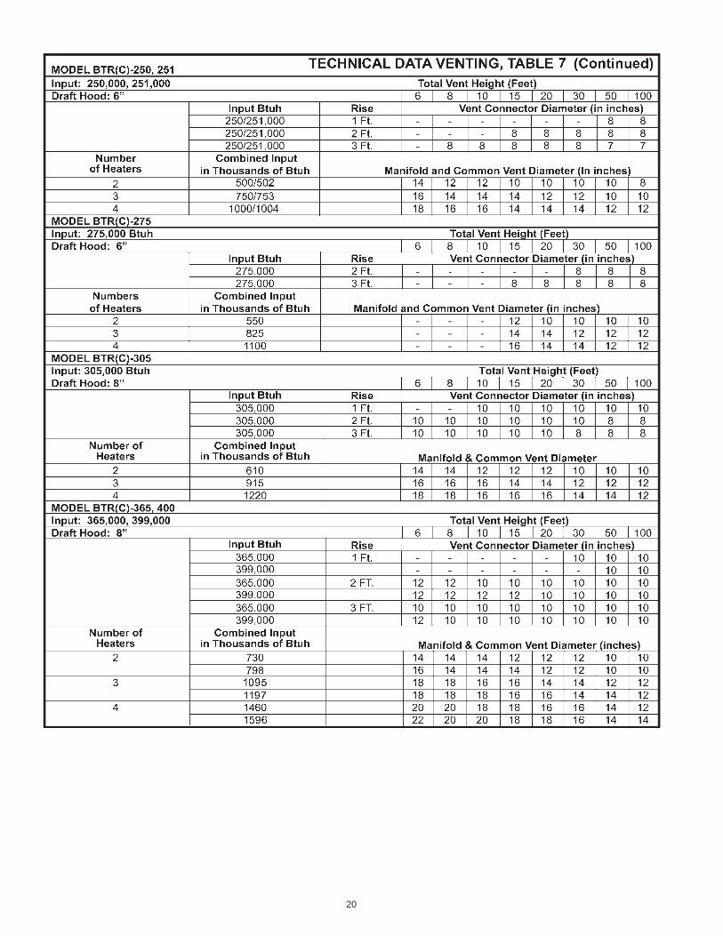
20
21
Vent installation
Seal all joints between the power venter and the vent termination. This is to prevent leakage of exhaust products into the room(s) due to positive pressure of blower.
The “Sequence of Operation” description will be the same with mechanical venting except;
When the water heater thermostat calls for heat:
Thermostat contacts “Close” and the power venter blower (120 VAC) is energized. Sufficient draft must be established for the “Draft Prover Switch (N.O.)” to “Close”. When the draft prover switch “Closes” the relay coil of the flue damper is energized.
multiple unit installation
For multiple unit installations, contact A. O. Smith, Technical Support Center at 1-800-527-1953.
water heater installation
mechanical Venting
single unit installation
When mechanical venting of these heaters is desired, the following kits are available.
models 120 through the 200/AA. O. Smith part number 9005381205
models 250/A through the 400/AA. O. Smith part number 9003434205
Where an approved power venter is to be installed to operate in conjunction with the water heater thermostat, the following codes must be adhered to. Field wiring should conform to the current edition of the National electrical Code NFPA 70. For Canadian installations the electrical connections and grounding shall be done in accordance with the current edition of the Canadian electrical Code CSA C22.1 and/or local codes.
water piping diagrams
This manual provides detailed water piping diagrams for typical methods of application for the water heaters, see Water Piping Diagrams beginning on page 40.
The water heater may be installed by itself, or with a separate storage tank. When used with a separate storage tank, the circulation may be either by gravity or by means of circulating pump. Adjust flow by throttling a full port ball valve installed in the circulating line on the outlet side of the pump. Never throttle flow on the suction side of a pump. See the Water Piping Diagrams beginning on page 40.
note: In addition to the factory installed Temperature-Pressure Relief Valve (T&P valve) on the water heater, each remote storage tank that may be installed and piped to a water heating appliance must also have its own properly sized, rated and approved Temperature-Pressure Relief Valve installed.
Call the toll free technical support phone number listed on the back cover of this manual for further assistance in sizing a T&P valve for remote storage tanks.
t&p ValVe discharge pipe
Explosion Hazard
Temperature-Pressure Relief Valvemust comply with ANSI Z21.22-CSA 4.4 and ASME code.
Properly sized temperature-pressure relief valve must beinstalled in opening provided.
Can result in overheating andexcessive tank pressure.
Can cause serious injury or death.
water line connections
The water piping installation must conform to these instructions and to all local code authority having jurisdiction. Good practice requires that all heavy piping be supported.
Read and observe all requirements in the following sections before installation of the water piping begins:
1. Water Temperature Control and Mixing Valves on page 13.
2. Dishwashing Machines on page 14.
3. Temperature-Pressure Relief Valve on page 14-15.
4. Closed Systems and Thermal expansion on page 14.
5. for multiple water heater installations see Water Piping Diagrams beginning on page 40.
water (potaBle) heating and space heating
1. All piping components connected to this unit for space heating applications shall be suitable for use with potable water.
2. Toxic chemicals, such as those used for boiler treatment, shall NeVeR be introduced into this system.
3. This unit may NeVeR be connected to any existing heating system or component(s) previously used with a non-potable water heating appliance.
4. When the system requires water for space heating at temperatures higher than required for domestic water purposes, a tempering valve must be installed. Please refer to installation diagrams beginning on page 40 of this manual for suggested piping arrangements.
5. These water heaters cannot be used in space heating applications only
thermometers (not supplied)
Thermometers should be obtained and field installed as shown in the installation diagrams.
Thermometers are installed in the system as a means of detecting the temperature of the outlet water supply.
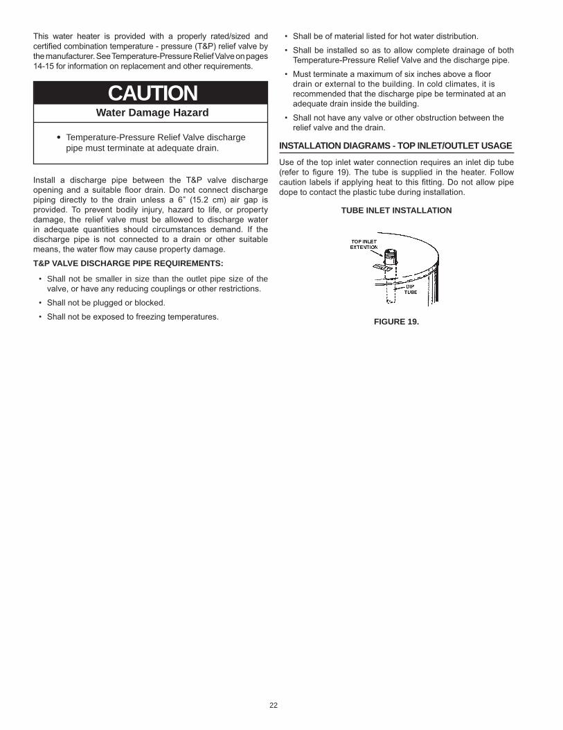
22
This water heater is provided with a properly rated/sized and certified combination temperature - pressure (T&P) relief valve by the manufacturer. See Temperature-Pressure Relief Valve on pages 14-15 for information on replacement and other requirements.
Water Damage Hazard
Temperature-Pressure Relief Valve dischargepipe must terminate at adequate drain.
•
CAUTION
Install a discharge pipe between the T&P valve discharge opening and a suitable floor drain. Do not connect discharge piping directly to the drain unless a 6” (15.2 cm) air gap is provided. To prevent bodily injury, hazard to life, or property damage, the relief valve must be allowed to discharge water in adequate quantities should circumstances demand. If the discharge pipe is not connected to a drain or other suitable means, the water flow may cause property damage.
t&p ValVe discharge pipe reQuirements:
• shall not be smaller in size than the outlet pipe size of the valve, or have any reducing couplings or other restrictions.
• Shall not be plugged or blocked.
• Shall not be exposed to freezing temperatures.
• Shall be of material listed for hot water distribution.
• Shall be installed so as to allow complete drainage of both Temperature-Pressure Relief Valve and the discharge pipe.
• Must terminate a maximum of six inches above a floor drain or external to the building. In cold climates, it is recommended that the discharge pipe be terminated at an adequate drain inside the building.
• Shall not have any valve or other obstruction between the relief valve and the drain.
installation diagrams - top inlet/outlet usage
Use of the top inlet water connection requires an inlet dip tube (refer to figure 19). The tube is supplied in the heater. Follow caution labels if applying heat to this fitting. Do not allow pipe dope to contact the plastic tube during installation.
tuBe inlet installation
figure 19.
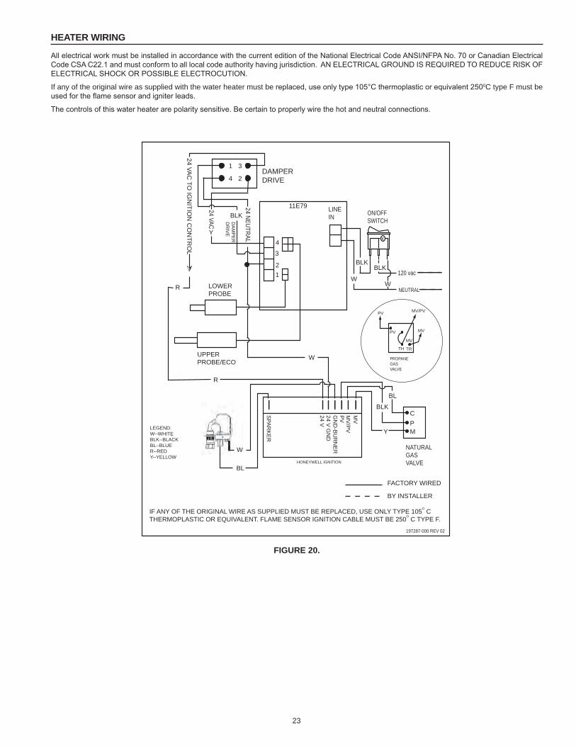
23
heater wiring
All electrical work must be installed in accordance with the current edition of the National electrical Code ANSI/NFPA No. 70 or Canadian electrical Code CSA C22.1 and must conform to all local code authority having jurisdiction. AN eLeCTRICAL GROUND IS ReQUIReD TO ReDUCe RISK OF eLeCTRICAL SHOCK OR POSSIbLe eLeCTROCUTION.
If any of the original wire as supplied with the water heater must be replaced, use only type 105°C thermoplastic or equivalent 2500C type f must be used for the flame sensor and igniter leads.
The controls of this water heater are polarity sensitive. be certain to properly wire the hot and neutral connections.
1 3
4 2
CPM
X
MV
MV
/PV
PV
24 V G
ND
24 V
SPA
RK
ER
GN
D-B
UR
NE
R
HONEYWELL IGNITION
DAMPERDRIVE
ON/OFFSWITCH
LOWERPROBE
UPPERPROBE/ECO
11E79 LINEIN
12
3
4
NEUTRAL
NATURALGASVALVE
PV
PV
TH TR
MV
MV/PV
MV
PROPANEGASVALVE
120 vac
24 VAC
TO IG
NITIO
N C
ON
TRO
L
DA
MP
ER
DR
IVE
24 VAC
24 NEUTRAL
FACTORY WIRED
BY INSTALLER
IF ANY OF THE ORIGINAL WIRE AS SUPPLIED MUST BE REPLACED, USE ONLY TYPE 105O CTHERMOPLASTIC OR EQUIVALENT. FLAME SENSOR IGNITION CABLE MUST BE 250O C TYPE F.
197287-000 REV 02
W
W
W
Y
BLK
BLKBLK
W
R
R
Y
BLK
BL
BL
LEGEND:W--WHITEBLK--BLACKBL--BLUER--REDY--YELLOW
figure 20.
24
gas piping
Contact your local gas service company to ensure that adequate gas service is available and to review applicable installation codes for your area.
Size the main gas line in accordance with Table 8. The figures shown are for straight lengths of pipe at 0.5 in. W.C. pressure drop, which is considered normal for low pressure systems. Note: Fittings such as elbows, tees and line regulators will add to the pipe pressure drop. Also refer to the latest version of the National Fuel Gas Code.
Schedule 40 Steel or Wrought Iron Pipe is the preferred material for the gas line of this water heater. It is imperative to follow the sizing recommendations in the latest version of the National Fuel Gas Code if Corrugated stainless steel Tubing (CssT) is used as the gas line for this water heater.
The heater is not intended for operation at higher than 14.0" W.C.- natural gas, (1/2 pound per square inch gage) supply gas pressure. exposure to higher supply pressure may cause damage to the gas valve which could result in fire or explosion. If overpressure has occurred such as through improper testing of gas lines or emergency malfunction of the supply system, the gas valve must be checked for safe operation. Make sure that the outside vents on the supply regulators and the safety vent valves are protected against blockage. These are parts of the gas supply system, not the heater. Vent blockage may occur during ice storms.
taBle 8. gas supply pipe lengths (in feet)maximum equivalent pipe length - natural gas only
Input rate (BTU/HR)
Schedule 40 Steel or Wrought Iron Pipe1/2" 3/4" 1" 1 1/4" 1 1/2"
120,000 20 70 200 200 200154,000 10 40 150 200 200180,000 - 30 100 200 200199,000 - 30 90 200 200250,000 - 20 60 200 200275,000 - 10 50 200 200310,000 - 10 40 150 200366,000 - - 30 100 200390,000 - - 20 100 200
fitting Type* equivalent length in feet45°ell 0.7 1.0 1.2 1.6 1.990°ell 1.6 2.1 2.6 3.5 4.0Tee 3.1 4.1 5.2 6.9 8.0
Natural Gas 0.60 Specific Gravity, 0.50" W.C. Pressure Drop*Screwed Fittings
It is important to guard against gas valve fouling from contaminants in gas ways. Such fouling may cause improper operation, fire or explosion.
If copper supply lines are used they must be internally tinned and certified for gas service. before attaching the gas line, be sure that all gas pipe is clean on the inside.
To trap any dirt or foreign material in the gas supply line, a sediment trap must be incorporated in the piping (see Figure 21). The sediment trap must be readily accessible and not subject to freezing conditions. Install in accordance with recommendations of serving gas suppliers. Refer to the latest version of the National Fuel Gas Code.
To prevent damage, care must be taken not to apply too much torque when attaching gas supply pipe to gas valve inlet.
Apply joint compounds (pipe dope) sparingly and only to the male threads of pipe joints. Do not apply compounds to the first two threads. Use compounds resistant to the action of liquefied petroleum gases.
gas meter siZe – natural gases onlybe sure the gas meter has sufficient capacity to supply the full rated gas input of the water heater as well as the requirements of all other gas fired equipment supplied by the meter. If gas meter is too small, ask the gas company to install a larger meter having adequate capacity.
gas piping and sediment trap installation
figure 21.
gas line leak testing
Fire and Explosion Hazard
Leak test before placing the waterheater in operation.Disconnect gas piping and main gasshutoff valve before leak testing.Install sediment trap in accordancewith NFPA 54.
Use joint compound or Teflon tapecompatible with propane gas.
Any time work is done on the gas supply system perform a leak test to avoid the possibility of fire or explosion.
1. For test pressures exceeding 1/2 psi (3.45 kPa) disconnect the water heater and its Main Gas Shutoff Valve from the gas supply piping system during testing, see Figure 21. The gas supply line must be capped when disconnected from the water heater.
2. For test pressures of 1/2 psi (3.45 kpa) or less, the water heater need not be disconnected, but must be isolated from the supply gas line by closing the Main Gas Shutoff Valve during testing.
3. Coat all supply gas line joints and connections upstream of the water heater with a non-corrosive soap and water solution to test for leaks. bubbles indicate a gas leak. Do not use matches, candles, flame or other sources of ignition for this purpose.
4. Repair any leaks before placing the water heater in operation.
purging
Gas line purging is required with new piping or systems in which air has entered.Purging should be performed per the current edition of NFPA 54 the National Fuel Gas Code.
25
is locked out, the power to the unit must be cycled to restart the Ignition Control.
8. If the pilot flame is proved during the ignition trial period, the Ignition Control turns off the spark Ignitor and opens the main Gas Valve.
9. The Ignition Control allows a 2 second pilot flame stabilization period to insure that the pilot flame is not extinguished by the main burner light-off process.
10. The Ignition Control monitors the Flame Sensor during the heating cycle. If the flame signal is lost, the Ignition Control shuts the Main Gas Valve and Pilot Gas Valve and re-starts the ignition process at step 4.
11. Once the unit is satisfied, the Ignition Control will shut off the Main Gas Valve and the Pilot Gas Valve and the unit will be in standby mode until another call for heat is initiated by the thermostat.
See the flow chart on page 26 for more information.
Light the water heater in accordance with the Lighting and Operation Instruction label on the water heater and in this manual on pages 27 and 28.
The water heaters covered by this manual are equipped with an electronic control system that automatically sequences the Igniter, the 24 VAC Gas Valve, the burner ignition, and flame sensing.
before attempting start up, thoroughly study and know the exact Sequence Of Operation. See written Sequence Of Operation on page 25 and Sequence Of Operation Flow Chart on page 26.
be certain that the water heater is full of water, that air is purged from the gas and water lines and that there are no leaks in the gas and water lines. ensure all inlet water valves are open.
filling the water heaterFollow these steps to fill the water heater prior to start up.1. Close the heater drain valve.
2. Open a nearby hot water faucet to permit air in system to escape.
3. Fully open the cold water inlet valve allowing the piping and water heater to fill with water.
4. Close hot water faucet opened in Step 2 as water starts to flow.
Read SeQUeNCe OF OPeRATION section of this manual prior to lighting and operating this water heater.
With above conditions satisfied, start the unit in accordance with the instructions on the operating label attached to the heater. For your convenience a copy of the instructions are shown on pages 27 and 28.
Fire or Explosion Hazard
Read instruction manual beforeinstalling, using or servicing
water heater.
To avoid risk of fire or explosion purge discharge must notenter into confined areas or spaces where ignition can occur.
The area must be well ventilated and all sources of ignitionmust be deactivated or removed.
Gas line purging is required with new piping or systems inwhich air has entered.
prior to start up
Installation and start up of this water heater requires abilities and skills equivalent to that of a licensed tradesman in the field involved, see Qualifications on page 6.
Do not place the water heater in operation if any part has been under water. Immediately call a qualified service technician to inspect the water heater and to replace any part of the control system and any gas control which has been under water.
operation
seQuence of operationThe following information will describe the Sequence of Operation for this water heater.
1. Switch power on to unit.
2. Thermostat calls for heat.
3. Ignition Control performs diagnostic self check on system components.
4. The Ignition Control begins the trial for ignition.
5. The Ignition Control turns on the Spark Igniter and opens the Pilot Gas Valve.
6. The Ignition Control monitors the Flame Sensor during the ignition trial period.
7. If the Ignition Control does not sense the pilot flame during the ignition trial period, the Ignition Control shuts the Pilot Gas Valve and turns off the Spark Igniter. Depending on the water heater model, the Ignition Control will either retry the ignition trial at step 4 or lockout the ignition sequence. If the ignition sequence
26
seQuence of operation flow chartDescription of this flow chart can be found in the “SeQUeNCe OF OPeRATION” section found on page 25.
flowchart 1.
A
A
IDLE(NOT POWERED)
“CALL FOR HEAT”RECEIVED FROM
THERMOSTAT
POWER TOMODULE ANDSELF CHECK
TRIAL FORIGNITION
(TIMER STARTED)
FLAMEPROVED?
CLOSE PILOTGAS VALVE
SPARK OFF
(BEFORE TRIAL FOR IGNITION TIMER EXPIRES)
SPARK OFF
OPEN MAIN GASVALVE
FLAMESTABILIZATION(2 SECONDS)
RUN
NO
NO
NO
YES
YES
YES
“CALLFOR HEAT”
ENDS?FLAMELOST?
CLOSE MAIN GASVALVE AND PILOT
GAS VALVE
CLOSE MAIN GASVALVE AND PILOT
GAS VALVE
SPARK ON OPEN PILOT GASVALVE
RETRY DELAY(5 MINUTES)
WAIT FOR“CALL FOR HEAT”TO BE REMOVED
ACTIVATE ALARMCONTACT(S)(OPTIONAL)
RETRY ORLOCKOUTMODEL?
LOCKOUT
RETRY
27
lighting & operation laBel
figure 22. laBel for natural gas models
for your safety read Before operating
operating instructions
for your safety read Before operating
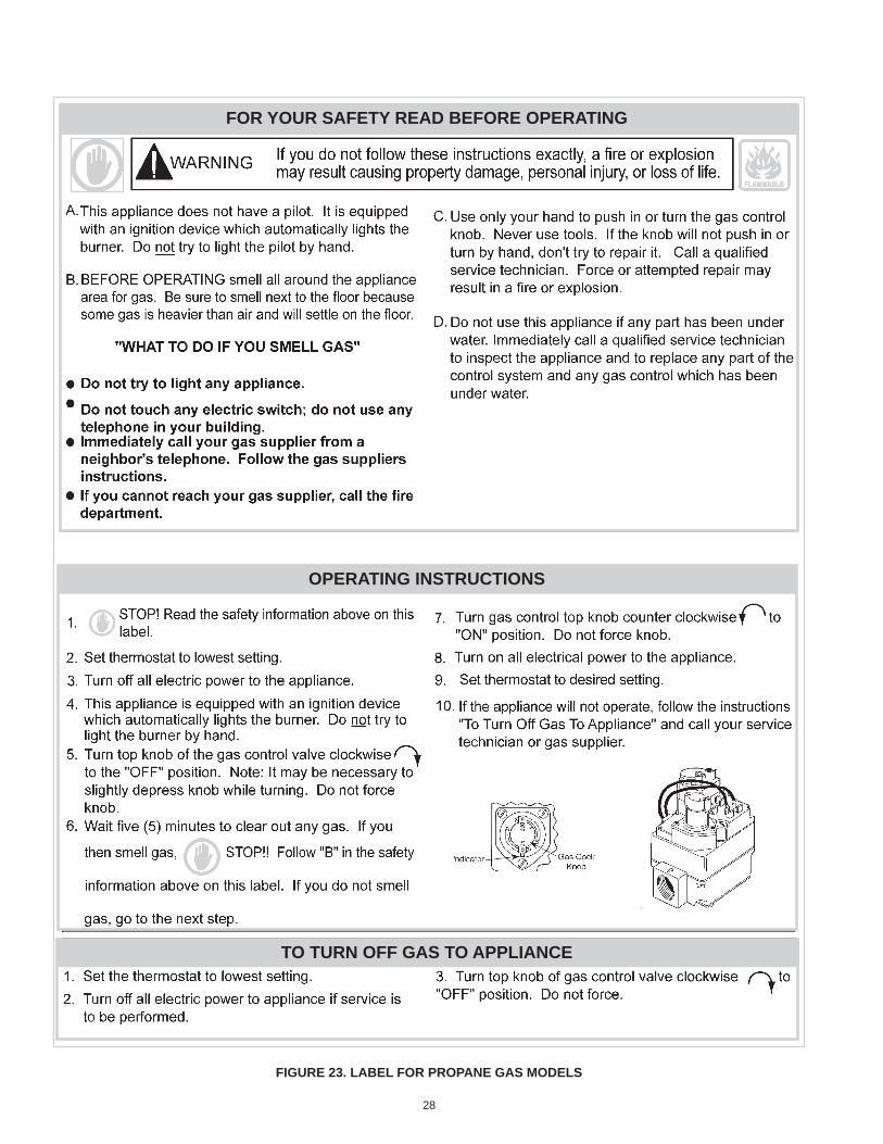
28
figure 23. laBel for propane gas models
for your safety read Before operating
operating instructions
to turn off gas to appliance
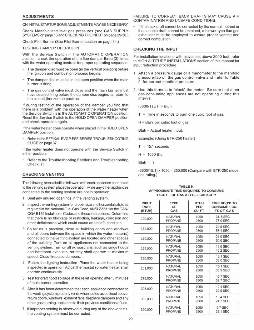
29
adjustments
ON INITIAL STARTUP SOMe ADJUSTMeNTS MAY be NeCeSSARY.
Check Manifold and inlet gas pressures (see GAS SUPPLY SYSTeMS on page 13 and CHeCKING THe INPUT on page 29-30.)
Check Pilot burner (See Pilot burner section on page 34.)
TEsTING DAmPER oPERATIoN
With the Service Switch in the AUTOMATIC OPeRATION position, check the operation of the flue damper three (3) times with the water operating controls for proper operating sequence:
• The damper disc must be open (in the vertical position) before the ignition and combustion process begins.
• The damper disc must be in the open position when the main burner is firing.
• The gas control valve must close and the main burner must have ceased firing before the damper disc begins its return to the closed (horizontal) position.
If during testing of the operation of the damper you find that there is a problem with the operation of the water heater when the Service Switch is in the AUTOMATIC OPeRATION position: Reset the Service Switch to the HOLD OPeN DAMPeR position and check operation again.
If the water heater does operate when placed in the HOLD OPeN DAMPeR position:
• Refer to the eFFIKAL RVGP-FSF-SeRIeS TROUbLeSHOOTING GUIDe on page 37.
If the water heater does not operate with the Service Switch in either position:
• Refer to the Troubleshooting Sections and Troubleshooting Checklist.
checking Venting
The following steps shall be followed with each appliance connected to the venting system placed in operation, while any other appliances connected to the venting system are not in operation.1. Seal any unused openings in the venting system.2. Inspect the venting system for proper size and horizontal pitch, as
required in the National Fuel Gas Code, ANSI Z223.1or the CAN/CGA b149 Installation Codes and these instructions. Determine that there is no blockage or restriction, leakage, corrosion and other deficiencies which could cause an unsafe condition.
3. So far as is practical, close all building doors and windows and all doors between the space in which the water heater(s) connected to the venting system are located and other spaces of the building. Turn on all appliances not connected to the venting system. Turn on all exhaust fans, such as range hoods and bathroom exhausts, so they shall operate at maximum speed. Close fireplace dampers.
4. Follow the lighting instruction. Place the water heater being inspected in operation. Adjust thermostat so water heater shall operate continuously.
5. Test for draft hood spillage at the relief opening after 5 minutes of main burner operation.
6. After it has been determined that each appliance connected to the venting system properly vents when tested as outlined above, return doors, windows, exhaust fans, fireplace dampers and any other gas burning appliance to their previous conditions of use.
7. If improper venting is observed during any of the above tests, the venting system must be corrected.
FAILURe TO CORReCT bACK DRAFTS MAY CAUSe AIR CONTAMINATION AND UNSAFe CONDITIONS.• If the back draft cannot be corrected by the normal method or
if a suitable draft cannot be obtained, a blower type flue gas exhauster must be employed to assure proper venting and correct combustion.
checking the input
For installation locations with elevations above 2000 feet, refer to HIGH ALTITUDe INSTALLATIONS section of this manual for input reduction procedure.
1. Attach a pressure gauge or a manometer to the manifold pressure tap on the gas control valve and refer to Table 9, for correct manifold pressure.
2. Use this formula to “clock” the meter. be sure that other gas consuming appliances are not operating during this interval.
(3600/T) x H = btuh
T = Time in seconds to burn one cubic foot of gas.
H = btu’s per cubic foot of gas.
btuh = Actual heater input.
example: (Using bTR-250 heater)
T = 15.1 seconds
H = 1050 btu
btuh = ?
(3600/15.1) x 1050 = 250,000 (Compare with BTR-250 model and rating.)
taBle 9.approximate time reQuired to consume
1 cu. ft. of gas at full capacity
input rate
(Btuh)
type of
gas
Btuh per
cu. ft.
time reQ’d to consume 1 cu.
ft. of gas
120,000 NATURAl PRoPANE
1050 2500
31. 5 SeC. 75.0 SeC.
154,000 NATURAl PRoPANE
1050 2500
24.5 SeC. 58.4 SeC.
180,000 NATURAl PRoPANE
1050 2500
21.0 SeC. 50.0 SeC.
199,000 NATURAl PRoPANE
1050 2500
19.0 SeC. 45.2 SeC.
250,000 NATURAl PRoPANE
1050 2500
15.1 SeC. 36.0 SeC.
251,000 NATURAl PRoPANE
1050 2500
15.1 SeC. 35.9 SeC.
275,000 NATURAl PRoPANE
1050 2500
13.7 SeC. 32.7 SeC.
305,000 NATURAl PRoPANE
1050 2500
12.4 SeC. 29.5 SeC.
365,000 NATURAl PRoPANE
1050 2500
10.4 SeC. 24.7 SeC.
390,000 NATURAl PRoPANE
1050 2500
9.7 SeC. 23.1 SeC.
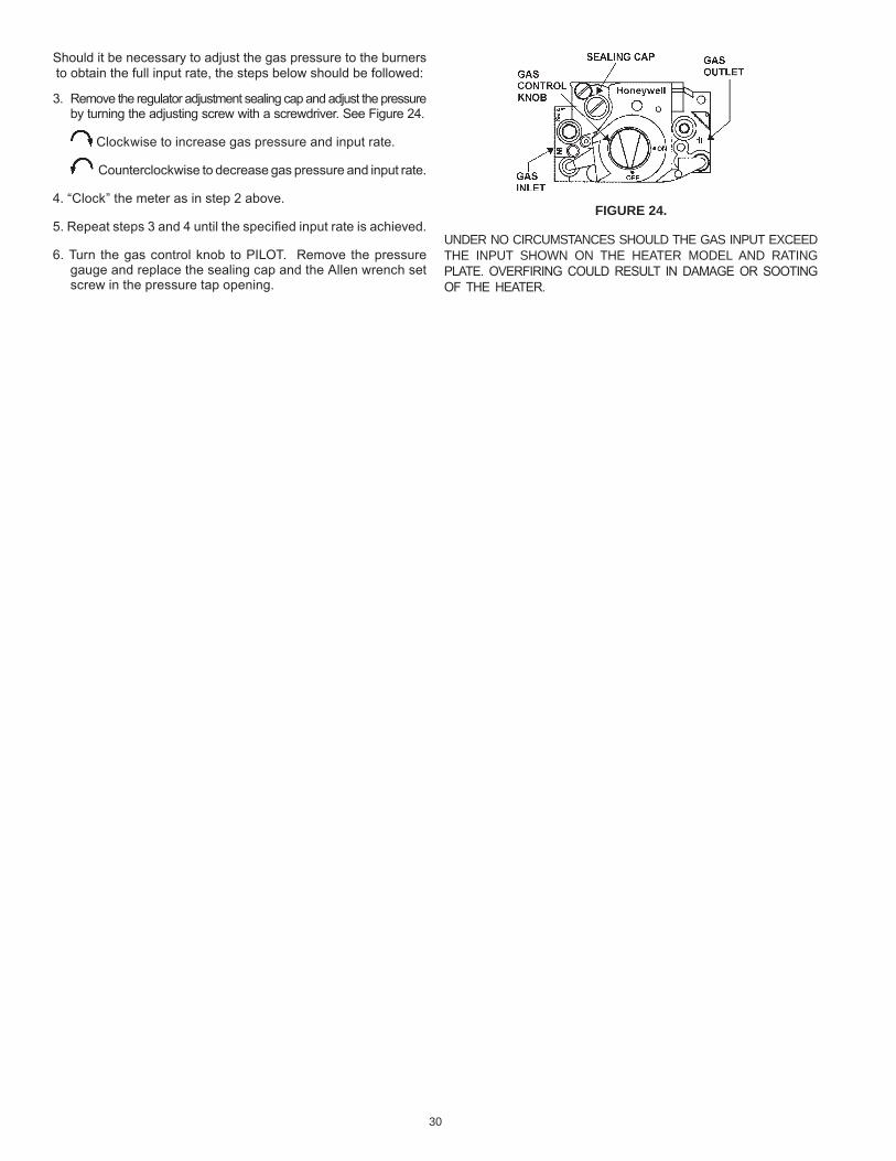
30
figure 24.
UNDER No CIRCUmsTANCEs sHoUlD THE GAs INPUT EXCEED THE INPUT sHoWN oN THE HEATER moDEl AND RATING PLATe. OVeRFIRING COULD ReSULT IN DAMAGe OR SOOTING OF THe HeATeR.
Should it be necessary to adjust the gas pressure to the burners to obtain the full input rate, the steps below should be followed:
3. Remove the regulator adjustment sealing cap and adjust the pressure by turning the adjusting screw with a screwdriver. See Figure 24.
Clockwise to increase gas pressure and input rate.
Counterclockwise to decrease gas pressure and input rate.
4. “Clock” the meter as in step 2 above.
5. Repeat steps 3 and 4 until the specified input rate is achieved.
6. Turn the gas control knob to PILOT. Remove the pressure gauge and replace the sealing cap and the Allen wrench set screw in the pressure tap opening.
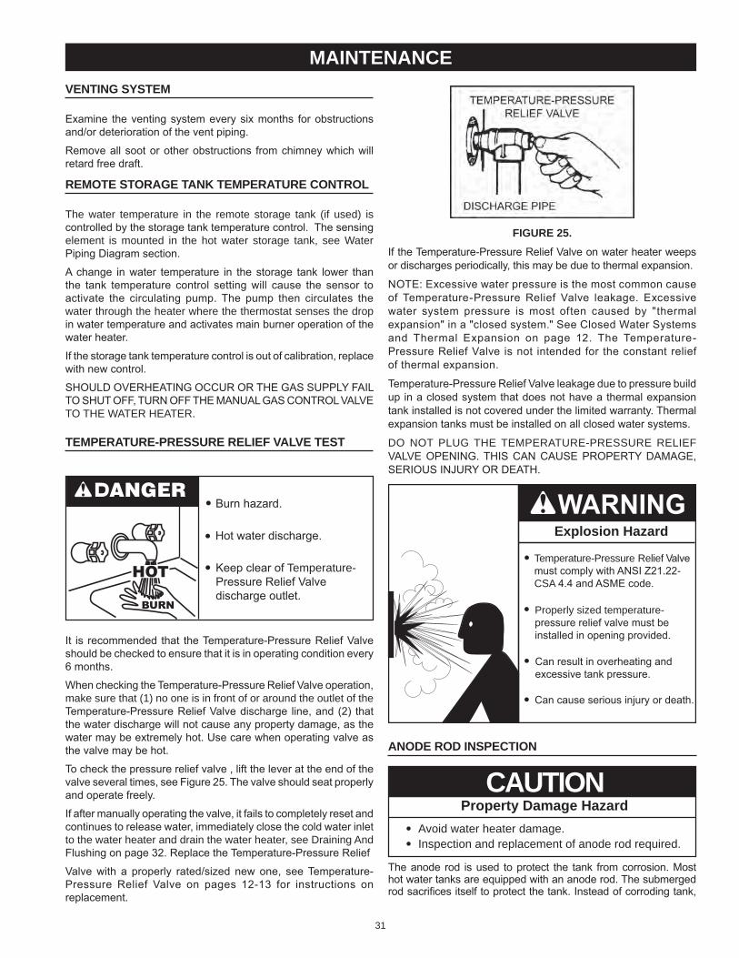
31
figure 25.
If the Temperature-Pressure Relief Valve on water heater weeps or discharges periodically, this may be due to thermal expansion.
NOTe: excessive water pressure is the most common cause of Temperature-Pressure Relief Valve leakage. excessive water system pressure is most often caused by "thermal expansion" in a "closed system." See Closed Water Systems and Thermal expansion on page 12. The Temperature-Pressure Relief Valve is not intended for the constant relief of thermal expansion.
Temperature-Pressure Relief Valve leakage due to pressure build up in a closed system that does not have a thermal expansion tank installed is not covered under the limited warranty. Thermal expansion tanks must be installed on all closed water systems.
Do NoT PlUG THE TEmPERATURE-PREssURE RElIEf VALVe OPeNING. THIS CAN CAUSe PROPeRTY DAMAGe, SeRIOUS INJURY OR DeATH.
explosion hazard
Temperature-Pressure Relief Valvemust comply with ANSI Z21.22-CsA 4.4 and ASMe code.
Properly sized temperature-pressure relief valve must beinstalled in opening provided.
Can result in overheating andexcessive tank pressure.
Can cause serious injury or death.
anode rod inspection
Property Damage HazardAvoid water heater damage.•Inspection and replacement of anode rod required.•
CAUTION
The anode rod is used to protect the tank from corrosion. Most hot water tanks are equipped with an anode rod. The submerged rod sacrifices itself to protect the tank. Instead of corroding tank,
Venting system
examine the venting system every six months for obstructions and/or deterioration of the vent piping.
Remove all soot or other obstructions from chimney which will retard free draft.
remote storage tank temperature control
The water temperature in the remote storage tank (if used) is controlled by the storage tank temperature control. The sensing element is mounted in the hot water storage tank, see Water Piping Diagram section.
A change in water temperature in the storage tank lower than the tank temperature control setting will cause the sensor to activate the circulating pump. The pump then circulates the water through the heater where the thermostat senses the drop in water temperature and activates main burner operation of the water heater.
If the storage tank temperature control is out of calibration, replace with new control.
SHOULD OVeRHeATING OCCUR OR THe GAS SUPPLY FAIL TO SHUT OFF, TURN OFF THe MANUAL GAS CONTROL VALVe To THE WATER HEATER.
temperature-pressure relief ValVe test
burn hazard.
Hot water discharge.
Keep clear of Temperature-Pressure Relief Valvedischarge outlet.
It is recommended that the Temperature-Pressure Relief Valve should be checked to ensure that it is in operating condition every 6 months.
When checking the Temperature-Pressure Relief Valve operation, make sure that (1) no one is in front of or around the outlet of the Temperature-Pressure Relief Valve discharge line, and (2) that the water discharge will not cause any property damage, as the water may be extremely hot. Use care when operating valve as the valve may be hot.
To check the pressure relief valve , lift the lever at the end of the valve several times, see Figure 25. The valve should seat properly and operate freely.
If after manually operating the valve, it fails to completely reset and continues to release water, immediately close the cold water inlet to the water heater and drain the water heater, see Draining And Flushing on page 32. Replace the Temperature-Pressure Relief
Valve with a properly rated/sized new one, see Temperature-Pressure Relief Valve on pages 12-13 for instructions on replacement.
maintenance
32
5. ensure the drain hose is secured before and during the entire flushing procedure. Flushing is performed with system water pressure applied to the water heater.
6. Open the water heater drain valve to flush the storage tank.7. Flush the water heater storage tank to remove sediment and
allow the water to flow until it runs clean.8. Close the water heater drain valve when flushing is completed.9. Remove the drain hose.10. Fill the water heater - see Filling The Water Heater in this manual.11. Turn on the electrical supply to place the water heater back
in operation.12. Allow the water heater to complete several heating cycles to
ensure it is operating properly.
recommended procedure for periodic remoVal of lime deposits from tank type commercial water heatersThe amount of calcium carbonate (lime) released from water is in direct proportion to water temperature and usage, see chart. The higher the water temperature or water usage, the more lime deposits are dropped out of the water. This is the lime scale which forms in pipes, heaters and on cooking utensils.Lime accumulation not only reduces the life of equipment but also reduces efficiency of the heater and increases fuel consumption.The usage of water softening equipment greatly reduces the hardness of the water. However, this equipment does not always remove all of the hardness (lime). For this reason it is recommended that a regular schedule for deliming be maintained.The time between cleaning will vary from weeks to months depending upon water conditions and usage.The depth of lime buildup should be measured periodically. Heaters equipped with cleanouts will have about 2" of lime buildup when the level of lime has reached the bottom of the cleanout opening. A schedule for deliming should then be set up,based on the amount of time it would take for a 1" buildup of lime. It is recommended that the water heater initially be inspected after 6 months.example 1:Initial inspection after 6 months shows 1/2" of lime accumulation. Therefore, the heater should be delimed once a year.example 2:Initial inspection after 6 months shows 2" of lime accumulation. Therefore, the heater should be delimed every 3 months.
figure 26.
water ions attack and eat away the anode rod. This does not affect water’s taste or color. The rod must be maintained to keep tank in operating condition.Anode rod deterioration depends on water conductivity, not necessarily water condition. A corroded or pitted anode rod indicates high water conductivity and should be checked and/or replaced more often than an anode rod that appears to be intact. Replacement of a depleted anode rod can extend the life of your water heater. Inspection should be conducted by a qualified technician, and at a minimum should be checked annually after the warranty period.Artificially softened water is exceedingly corrosive because the process substitutes sodium ions for magnesium and calcium ions.The use of a water softener may decrease the life of the water heater tank.The anode rod should be inspected after a maximum of three years and annually thereafter until the condition of the anode rod dictates its replacement. Anode replacement is not covered by warranty. NOTe: artificially softened water requires the anode rod to be inspected annually.
draining and flushing
Burn harzard.
Hot water discharge.
Keep hands clear of drainvalve discharge.
It is recommended that the water heater storage tank be drained and flushed every 6 months to reduce sediment buildup. The water heater should be drained if being shut down during freezing temperatures. See Features And Components in this manual for the location of the water heater components described below.to drain the water heater storage tank:1. Turn off the electrical supply to the water heater.2. Turn off the gas supply at the Main Gas Shutoff Valve if the
water heater is going to be shut down for an extended period.3. ensure the cold water inlet valve is open.4. Open a nearby hot water faucet and let the water run until
the water is no longer hot.5. Close the cold water inlet valve to the water heater.6. Connect a hose to the water heater drain valve and terminate
it to an adequate drain.7. Open the water heater drain valve and allow all the water to
drain from the storage tank.8. Close the water heater drain valve when all water in the
storage tank has drained.9. Close the hot water faucet opened in Step 4.10. If the water heater is going to be shut down for an extended
period, the drain valve should be left open.
to flush the water heater storage tank:1. Turn off the electrical supply to the water heater.2. ensure the cold water inlet valve is open.3. Open a nearby hot water faucet and let the water run until
the water is no longer hot. Then close the hot water faucet.4. Connect a hose to the drain valve and terminate it to an
adequate drain.
33
Explosion Hazard
Flammable hydrogen gasesmay be present.
Keep all ignition sources awayfrom faucet when turning onhot water.
Do not smoke or have open flame or sparks in vicinity of heater. Do not mix UN•LIMe with other chemicals. Do not allow contact with magnesium, aluminum or galvanized metals.
Chemical Hazard
• Product contains phosphoric acid.
• Keep out of reach of children.
• Use rubber or neoprene gloves.
Contains phosphoric acid. In case of external contact, flush with cool water. If irritation persists, get medical attention. If swallowed, give 1 or 2 glasses of water or milk and call physician.
Get immediate medical attention for eyes. Keep out of reach of children.note: the use of ruBBer or neoprene gloVes is recommended, especially if you haVe any open sores or cuts to aVoid unnecessary irritation or discomfort.1. Turn off fuel and/or power supply to heater. Also, turn off power
to any electrical device or equipment, which is attached, or part of the system.
2. Open hot water side of faucet closest to heater and allow water to run until it is cool enough to handle safely.
3. Close cold water inlet valve to heater.4. Connect hose to drain valve at bottom of heater and start draining
heater into suitable floor drain area.5. Remove pressure relief valve while heater is draining. NOTe:
Do not replace pressure relief valve until deliming is completed. Pressure relief valve opening will also act as a vent in case of possible contact between the delimer and the anode rod(s), which may produce flammable hydrogen-air mixtures.
6. If pressure relief valve appears to be limed-up, place it in a clean glass or plastic container adequate in size so that you can pour enough UN•LIMe® into container to cover the valve and allow space for foaming. When foaming stops, run fresh cool water into the container and rinse the pressure relief valve for a few minutes.
7. If heater does not drain completely after a reasonable length of time, turn off the main water supply valve to stop water from entering the tank due to a by-pass problem or defective cold water inlet valve. Also, check for clogged drain valve opening. Heater must be completely drained before introducing UN•LIMe.
8. Remove the cleanout cover and place a clean plastic bucket next to the cleanout opening.Partially open the cold water inlet valve to allow time to accomplish the following and then close the valve.
deliming solVents
UN•LIMe is recommended for deliming. UN•LIMe is a patented food grade acid which is safe to handle and does not create the harmful fumes which are associated with other products.
UN•LIMe may be obtained from your dealer, distributor or water heater manufacturer. Order Part Number 9005416105, 1 gallon, packed 4 gallons per case or Part Number 9005417105, 5 gallon container.
NOTe: Un•Lime is not available for use in Canada.
Hydrochloric base acids are not recommended for use on glass lined tanks.
Observe handling instructions on label of product being used.
tank cleanout procedure
The following practices will ensure longer life and enable the unit to operate at its designed efficiency:
1. Once a month the heater should be flushed. Open the drain valve and allow two gallons of water to drain from the heater. Inlet water valve should remain open to maintain pressure in tank.
2. A cleanout opening is provided for periodic cleaning of the tank. Gas must be shut off and heater drained before opening cleanout.
To clean heater through cleanout opening, proceed as follows:
3. Drain heater.
4. Remove outer cover plate from lower side of heater jacket.
5. Remove six (6) hex head screws securing tank cleanout plate and remove plate.
6. Remove lime, scale, or sediment using care not to damage the glass lining.
7. Inspect cleanout plate gasket, if new gasket is required, replace with part no. 9004099215.
8. Install cleanout plate. be sure to draw plate up tight by tightening screws securely.
9. Replace outer jacket cover plate.
In some water areas the sediment might not be removed by this method and may result in the water heater making rumbling or boiling noises. To dissolve and remove these more stubborn mineral deposits, UN•LIMe Professional Delimer should be used.
deliming using flo-jug method
UN•LIMe in the 5 gallon size is recommended for deliming of all models. Contact your local dealer, distributor or, water heater manufacturer:
Telephone: (800) 433-2545
Fax: (800) 433-2515
Website: www.hotwater.com/parts
Prepare the Water Heater
To delime the water heater using the Flo-Jug method, first prepare the heater for deliming.
34
figure 27.
pilot BurnerAt least once a year, check the pilot burner, Figure 29, and the main burner, Figure 30, for proper operation. See Figure 28 for the location of the Pilot burner and the Main burners. For access to pilot, unfasten two screws to burner cover and remove. Locate the burner with pilot and remove screw holding burner to manifold. Unfasten pilot tubing from valve and slide out burner and pilot.Servicing of the pilot burner includes keeping pilot free of lint, cleaning the burner head, the primary air opening and the orifice of the pilot burner.
figure 28.
figure 29.
Pilot burner flame is affected by:.1. Low gas pressure.
• Adjust pilot flame by means of the pilot gas adjustment located on the gas control valve. See Figure 31.
• The pilot flame should envelop sensing device with 5/8” (1.6cm) flame, Figure30. Remove pilot adjustment cover screw, Figure 31. Turn inner adjustment screw clockwise to decrease, or counterclockwise to increase pilot flame. be sure to replace cover screw on gas control valve after adjustment to prevent possible gas leakage.
2. Clogged pilot burner orifice.• Clean or replace orifice. A clogged orifice will restrict gas flow.
While the water is being run through the tank, insert a stiff wire, copper tube flattened at one end or an opened wire coat hanger through the cleanout opening and scrape out any loose deposits of scale or sediment. This is an economical way to avoid unnecessary usage of the deliming solution.
Repeat the opening and closing of the cold water inlet valve as necessary but be sure the heater is completely drained when ready to introduce the UN•LIMe.
Upon completion, reinstall the cleanout cover and use a new cleanout cover gasket (part number 9004099215).
Remove the drain valve.
9. Install the long plastic male adapter insert fitting into the drain valve opening of heater after applying Teflon tape or paste to threads. Tighten firmly by hand and use wrench or adjustable pliers to check for secure connection. Do not over tighten to avoid damage to threads and fittings.
Prepare the Up-N-Down Transfer Kit
The next step is the preparation on the Up-N-Down Transfer Kit, if you have not already done so:
1. With the 5 gallon Up-N-Down container in the vertical position, unscrew the plastic vent cap in the handle and pierce the plastic membrane over the vent boss under the cap to allow the container to vent.
note: If your container does not have the vent cap and vent boss, drill a 3/16” hole in the handle. When you have finished deliming you will be able to plug this drilled vent with the stainless steel screw that is supplied with the kit.
2. Remove the container’s cap and cut the plastic membrane located in the 3/4” IPT opening in the cap. Take care to not damage the threads.
3. Find the 3/4” male adapter, apply teflon tape to the threaded end and screw it into the 3/4” IPT opening in the cap.
4. Put cap with male adapter back on the container and slide 3/4” hose over end of male adapter and fasten in place using hose clamp provided.
Delime using flo-Jug method
5. Slide the hose clamp over end of hose and slide hose over the male adapter in the water heater drain opening and secure in place using hose clamp.
6. Lift container to the “Pour” Position, see Figure 27, being careful to keep the vent in the handle above the liquid level and pour the UN•LIMe into the heater.
7. Lower container, you may have to place the container on its empty carton to prevent the UN•LIMe from flowing back into the container.
8. Let UN•LIMe remain in the heater for 5 minutes and then lower the container to the “Drain” Position, see Figure 27.
9. Deliming activity is indicated by foaming on the surface of the UN•LIMe. If there is deliming activity, repeat steps 6 thru 8.
Normally, lime removal will be completed within one hour. Severe build-up of lime may take longer than an hour to complete descaling.
Note: To check UN•LIMe for continued use, place some scale or white chalk in a glass with a small amount of UN•LIMe. If the material is vigorously dissolved by the UN•LIMe, it can be reused; if not, the UN•LIMe should be replaced.
35
gas control ValVe
Figure 31 shows the two types of combination gas control valvesused on these heaters.If gas control valve becomes defective, repairs should not be attempted. A new valve should be installed in place of defective one.
lp ValVe
natural ValVe
figure 31.
serViceThe installer may be able to observe and correct certain problems which may arise when the unit is put into operation. HOWeVeR, it is recommended that only a qualified service technician or qualified agencys, using appropriate test equipment, be allowed to service the heater.As preliminary step, check wiring against diagram, check for grounded, broken or loose wires. Check all wire ends to be sure that they are making good contact.
electrical serVicing
LAbeL ALL WIReS PRIOR TO DISCONNeCTION WHeN SeRVICING CONTROLS. WIRING eRRORS CAN CAUSe IMPROPeR AND DANGeROUS OPeRATION.
VeRIFY PROPeR OPeRATION AFTeR SeRVICING.
Pilot sensing device must sense a flame before sparking will stop.Loose wires or a draft may cause intermittent or abnormal sparking. To eliminate this condition, first correct loose wiring condition, and then, if necessary, increase pilot flame.
main BurnerThe main burner, figure 30, should display the following characteristics:
• Cause rapid ignition and carry over of flame across entire burner.• Give reasonably quiet operation during ignition, burning and extinction.• Cause no excessive lifting of flame from burner ports.
If the preceding burner characteristics are not evident, check for accumulation of lint or other foreign material that restricts or other foreign material that restricts or blocks air openings to burner or heater.To clean main burners:1. Remove main burners from unit.2. Check that burner venturi and ports are free of foreign matter.
3. Clean burners with bristle brush and/or vacuum cleaner DO NOT distort burner ports or pilot location.
4. Reinstall burners in unit. Make sure front and rear of burners are installed correctly in burner support brackets.
Also check for good flow of combustion and ventilating air to the unit.
typical pilot and main Burner flames
figure 30.
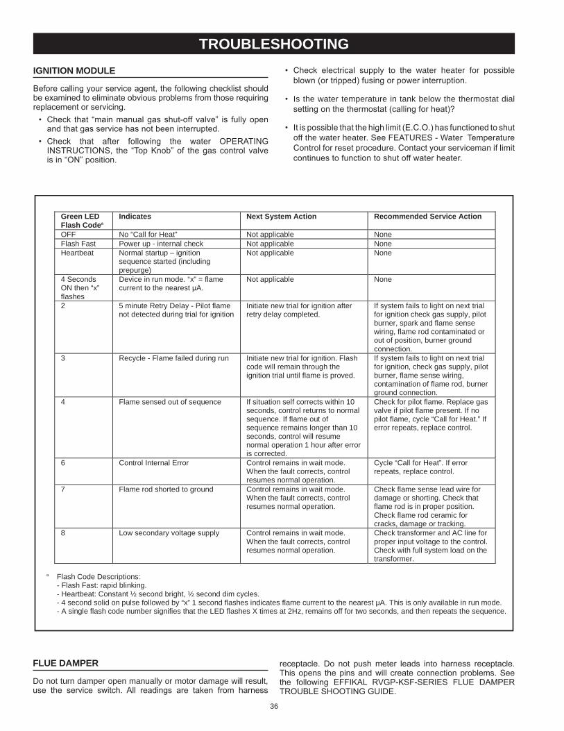
36
receptacle. Do not push meter leads into harness receptacle. This opens the pins and will create connection problems. See the following eFFIKAL RVGP-KSF-SeRIeS FLUe DAMPeR TROUbLe SHOOTING GUIDe.
Green LED Flash Code a
Indicates Next System Action Recommended Service Action
OFF No “Call for Heat” Not applicable None Flash Fast Power up - internal check Not applicable None Heartbeat Norma l startup – ignition
sequence started (including prepurge)
Not applicable None
4 Seconds ON then “x” flashes
Device in run mode. “x” = flame current to the nearest μ A.
Not applicable None
2 5 minute Retry Delay - Pilot flame not detected during trial for ignition
Initiate new trial for ignition after retry delay completed.
If system fails to light on next trial for ignition check gas supply, pilot burner, spark and flame sense wiring, flame rod contaminated or out of position, burner ground connection.
3 Recycle - Flame failed during run Initiate new trial for ignition. Flash code will remain through the ignition trial until flame is proved.
If system fails to light on next trial for ignition, check gas supply, pilot burner, flame sense wiring, contamination of flame rod, burner ground connection.
4 Flame sensed out of sequence If situation self corrects within 10 seconds, control returns to normal sequence. If flam e out of sequence remains longer than 10 seconds, control will resume normal operation 1 hour after error is corrected.
Check for pilot flame. Replace gas valve if pilot flame present. If no pilot flame, cycle “Call for Heat.” If error repeats, replace con trol.
6 Control Internal Error Control remains in wait mode. When the fault corrects, control resumes normal operation.
Cycle “Call for Heat”. If error repeats, replace control.
7 Flame rod shorted to ground Control remains in wait mode. When the fault corrects, control resumes normal operation.
Check flame sense lead wire for damage or shorting. Check that flame rod is in proper position. Check flame rod ceramic for cracks, damage or tracking.
8 Low secondary voltage supply Control remains in wait mo de. When the fault corrects, control resumes normal operation.
Check transformer and AC line for proper input voltage to the control. Check with full system load on the transformer.
a Flash Code Descriptions:
- Flash Fast: rapid blinking. - Heartbeat: Constant ½ second bright, ½ second dim cycles. - 4 second solid on pulse followed by “x” 1 second flashes indicates flame current to the nearest μ A. This is only available in run mode. - A single flash code number signifies that the LED flashes X times at 2H z, remains off for two seconds, and then repeats the sequence.
trouBleshootingignition module
before calling your service agent, the following checklist should be examined to eliminate obvious problems from those requiring replacement or servicing.
• Check that “main manual gas shut-off valve” is fully open and that gas service has not been interrupted.
• Check that after following the water OPeRATING INSTRUCTIONS, the “Top Knob” of the gas control valve is in “ON” position.
• Check electrical supply to the water heater for possible blown (or tripped) fusing or power interruption.
• Is the water temperature in tank below the thermostat dial setting on the thermostat (calling for heat)?
• It is possible that the high limit (e.C.O.) has functioned to shut off the water heater. See FeATUReS - Water Temperature Control for reset procedure. Contact your serviceman if limit continues to function to shut off water heater.
flue damper
Do not turn damper open manually or motor damage will result, use the service switch. All readings are taken from harness
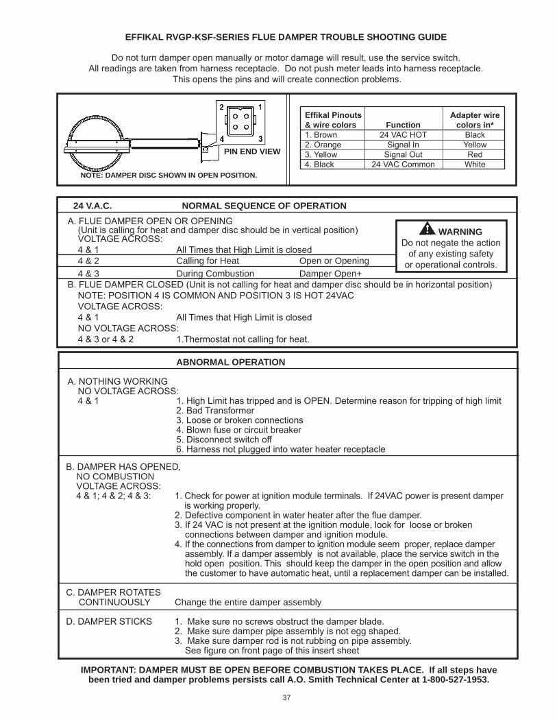
37
pin end View
24 V.a.c. normal seQuence of operation
b. DAMPeR HAS OPeNeD, No ComBUsTIoN VOLTAGe ACROSS: 4 & 1; 4 & 2; 4 & 3: 1. Check for power at ignition module terminals. If 24VAC power is present damper is working properly. 2. Defective component in water heater after the flue damper. 3. If 24 VAC is not present at the ignition module, look for loose or broken connections between damper and ignition module. 4. If the connections from damper to ignition module seem proper, replace damper assembly. If a damper assembly is not available, place the service switch in the hold open position. This should keep the damper in the open position and allow the customer to have automatic heat, until a replacement damper can be installed.
C. DAMPeR ROTATeS CoNTINUoUsly Change the entire damper assembly
D. DAMPeR STICKS 1. Make sure no screws obstruct the damper blade. 2. Make sure damper pipe assembly is not egg shaped. 3. Make sure damper rod is not rubbing on pipe assembly. See figure on front page of this insert sheet
aBnormal operation
A. NOTHING WORKING NO VOLTAGe ACROSS: 4 & 1 1. High Limit has tripped and is OPeN. Determine reason for tripping of high limit 2. bad Transformer 3. Loose or broken connections 4. blown fuse or circuit breaker 5. Disconnect switch off 6. Harness not plugged into water heater receptacle
A. FLUe DAMPeR OPeN OR OPeNING (Unit is calling for heat and damper disc should be in vertical position) VOLTAGe ACROSS: 4 & 1 All Times that High Limit is closed 4 & 2 Calling for Heat open or opening 4 & 3 During Combustion Damper open+b. FLUe DAMPeR CLOSeD (Unit is not calling for heat and damper disc should be in horizontal position) NOTe: POSITION 4 IS COMMON AND POSITION 3 IS HOT 24VAC VOLTAGe ACROSS: 4 & 1 All Times that High Limit is closed NO VOLTAGe ACROSS: 4 & 3 or 4 & 2 1.Thermostat not calling for heat.
effikal rVgp-ksf-series flue damper trouBle shooting guide
Do not turn damper open manually or motor damage will result, use the service switch.All readings are taken from harness receptacle. Do not push meter leads into harness receptacle.
This opens the pins and will create connection problems.
warningDo not negate the action
of any existing safetyor operational controls.
important: damper must Be open Before comBustion takes place. if all steps have been tried and damper problems persists call a.o. smith technical center at 1-800-527-1953.
note: damper disc shown in open position.
EffikalPinouts Adapterwire& wire colors function colors in*1. brown 24 VAC HOT black2. Orange Signal In Yellow3. Yellow Signal Out Red4. black 24 VAC Common White
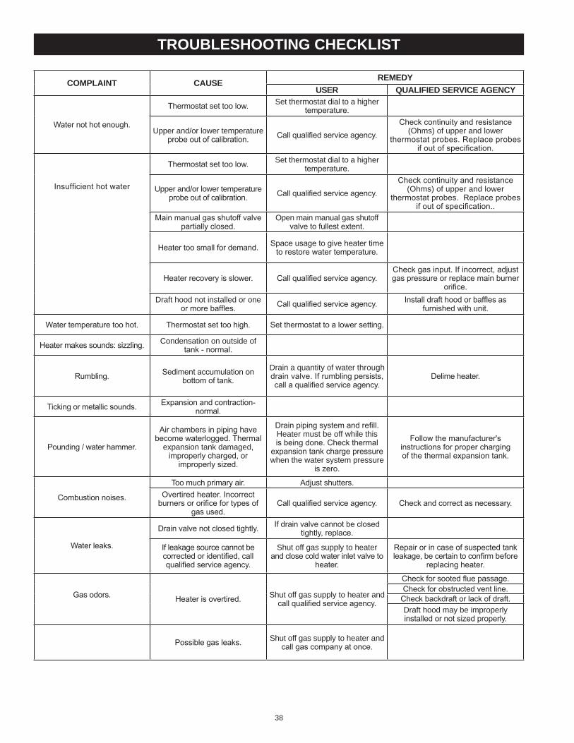
38
complaint cause remedyuser Qualified serVice agency
Water not hot enough.
Thermostat set too low. set thermostat dial to a higher temperature.
Upper and/or lower temperature probe out of calibration. Call qualified service agency.
Check continuity and resistance (ohms) of upper and lower
thermostat probes. Replace probes if out of specification.
Insufficient hot water
Thermostat set too low. set thermostat dial to a higher temperature.
Upper and/or lower temperature probe out of calibration. Call qualified service agency.
Check continuity and resistance (ohms) of upper and lower
thermostat probes. Replace probes if out of specification..
Main manual gas shutoff valve partially closed.
open main manual gas shutoff valve to fullest extent.
Heater too small for demand. Space usage to give heater time to restore water temperature.
Heater recovery is slower. Call qualified service agency.Check gas input. If incorrect, adjust gas pressure or replace main burner
orifice.Draft hood not installed or one
or more baffles. Call qualified service agency. Install draft hood or baffles as furnished with unit.
Water temperature too hot. Thermostat set too high. Set thermostat to a lower setting.
Heater makes sounds: sizzling. Condensation on outside of tank - normal.
Rumbling. Sediment accumulation on bottom of tank.
Drain a quantity of water through drain valve. If rumbling persists, call a qualified service agency.
Delime heater.
Ticking or metallic sounds. expansion and contraction-normal.
Pounding / water hammer.
Air chambers in piping have become waterlogged. Thermal
expansion tank damaged, improperly charged, or
improperly sized.
Drain piping system and refill. Heater must be off while this is being done. Check thermal
expansion tank charge pressure when the water system pressure
is zero.
Follow the manufacturer'sinstructions for proper chargingof the thermal expansion tank.
Combustion noises.
Too much primary air. Adjust shutters.Overtired heater. Incorrect
burners or orifice for types of gas used.
Call qualified service agency. Check and correct as necessary.
Water leaks.
Drain valve not closed tightly. If drain valve cannot be closed tightly, replace.
If leakage source cannot be corrected or identified, call qualified service agency.
shut off gas supply to heater and close cold water inlet valve to
heater.
Repair or in case of suspected tank leakage, be certain to confirm before
replacing heater.
Gas odors. Heater is overtired. shut off gas supply to heater and call qualified service agency.
Check for sooted flue passage.Check for obstructed vent line.
Check backdraft or lack of draft.Draft hood may be improperly installed or not sized properly.
Possible gas leaks. shut off gas supply to heater and call gas company at once.
trouBleshooting checklist
39
c. A sulfate reducing bacteria which has accumulated within the water heater (this harmless bacteria is nontoxic to humans).
d. An excess of active hydrogen in the tank. This is caused by the corrosion protective action of the anode rod.
Smelly water may be eliminated or reduced in some water heater models by replacing the anode rod(s) with one of less active material, and then chlorinating water heater tank and all water lines.Contact the local water heater supplier or service agency for further information concerning an Anode Rod Replacement Kit and this chlorination treatment.
If smelly water persists after anode rod replacement and chlorination treatment, we can only suggest that chlorination or aeration of the water supply be considered to eliminate the water problem.
Do not remove the anode rod leaving the tank unprotected. by doing so, all warranty on the water heater tank is voided.
“air” in hot water faucets
HYDROGeN GAS: Hydrogen gas can be produced in a hot water system that has not been used for a long period of time (generally two weeks or more). Hydrogen gas is extremely flammable and explosive. To prevent the possibility of injury under these conditions, we recommend the hot water faucet, located farthest away, be opened for several minutes before any electrical appliances which are connected to the hot water system are used (such as a dishwasher or washing machine). If hydrogen gas is present, there will probably be an unusual sound similar to air escaping through the pipe as the hot water faucet is opened. There must be no smoking or open flame near the faucet at the time it is open.
high water temperature shut off systemThis water heater is equipped with a manual reset type high limit (energy Cutout) switch. The high limit switch interrupts the main burner gas flow should water temperature reach 203°F (95°C).
In the event of high limit switch operation, the water heater cannot be restarted unless the water temperature is reduced to approximately 120F (49C). The high limit reset button on the front of the thermostat then needs to be depressed. See Figure 2 for the location of the reset button.
start up conditions
smoke/odor
It is not uncommon to experience a small amount of smoke and odor during the initial start-up. This is due to burning off of oil from metal parts, and will disappear in a short while.
strange sounds
Possible noises due to expansion and contraction of some metal parts during periods of heat-up and cool-down do not necessarily represent harmful or dangerous conditions.Condensation causes sizzling and popping within the burner area during heating and cooling periods and should be considered normal. See “Condensation" section in this manual.
condensation
Whenever the water heater is filled with cold water, some condensate will form while the burner is on. A water heater may appear to be leaking when in fact the water is condensation. This usually happens when:a. A new water heater is filled with cold water for the first time.b. burning gas produces water vapor in water heaters,
particularly high efficiency models where flue temperatures are lower.
c. Large amounts of hot water are used in a short time and the refill water in the tank is very cold.
Moisture from the products of combustion condense on the cooler tank surfaces and form drops of water which may fall onto the burner or other hot surfaces to produce a “sizzling” or “frying” noise.
operational conditions
hot water odor
In each water heater there is installed at least one anode rod forcorrosion protection of the tank. Certain water conditions will cause a reaction between this rod and the water. The most common complaint associated with the anode rod is one of a “rotten egg smell” in the hot water. The smell is a result of four factors which must all be present for the odor to develop:a. A concentration of sulfate in the supply water.b. Little or no dissolved oxygen in the water.
for your information
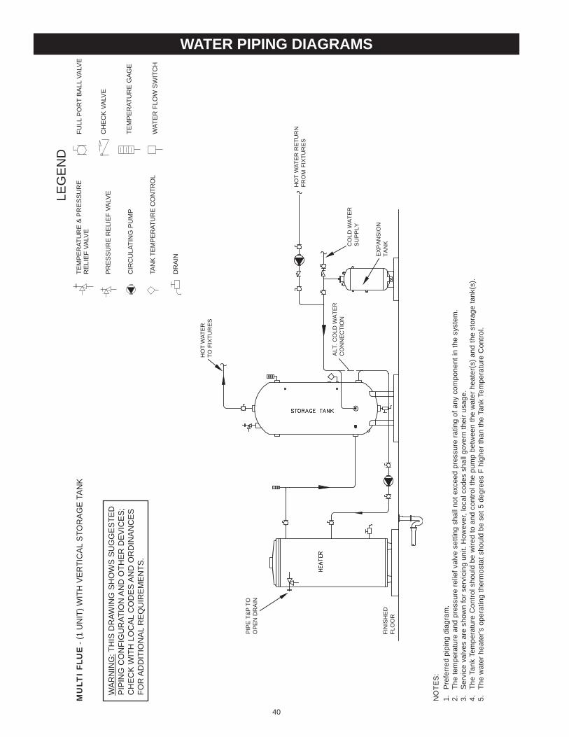
40
water piping diagrams
NO
TES
:1.
P
refe
rred
pip
ing
diag
ram
.2.
Th
e te
mpe
ratu
re a
nd p
ress
ure
relie
f val
ve s
ettin
g sh
all n
ot e
xcee
d pr
essu
re ra
ting
of a
ny c
ompo
nent
in th
e sy
stem
.3.
S
ervi
ce v
alve
s ar
e sh
own
for s
ervi
cing
uni
t. H
owev
er, l
ocal
cod
es s
hall
gove
rn th
eir u
sage
.4.
Th
e Ta
nk T
empe
ratu
re C
ontro
l sho
uld
be w
ired
to a
nd c
ontro
l the
pum
p be
twee
n th
e w
ater
hea
ter(
s) a
nd th
e st
orag
e ta
nk(s
).5.
Th
e w
ater
hea
ter’s
ope
ratin
g th
erm
osta
t sho
uld
be s
et 5
deg
rees
F h
ighe
r tha
n th
e Ta
nk T
empe
ratu
re C
ontro
l.
MU
LTI
FLU
E -
(1 U
NIT
) WIT
H V
ER
TIC
AL
STO
RA
GE
TA
NK
LEG
EN
DTE
MP
ER
ATU
RE
& P
RE
SS
UR
ER
ELI
EF
VALV
E
PR
ES
SU
RE
RE
LIE
F VA
LVE
CIR
CU
LATI
NG
PU
MP
TAN
K TE
MPE
RAT
UR
E C
ON
TRO
L
DR
AIN
FULL
PO
RT
BA
LL V
ALV
E
TEM
PE
RAT
UR
E G
AG
E
WAT
ER
FLO
W S
WIT
CH
CH
EC
K V
ALV
EW
AR
NIN
G: T
HIS
DR
AWIN
G S
HO
WS
SU
GG
ES
TED
PIP
ING
CO
NFI
GU
RAT
ION
AN
D O
THE
R D
EV
ICE
S;
CH
EC
K W
ITH
LO
CA
L C
OD
ES
AN
D O
RD
INA
NC
ES
FOR
AD
DIT
ION
AL
RE
QU
IRE
ME
NTS
.
FIN
ISH
ED
FLO
OR
HO
T W
ATE
RTO
FIX
TUR
ES
CO
LD W
ATE
RS
UP
PLY
EX
PA
NS
ION
TAN
K
ALT
. CO
LD W
ATE
RC
ON
NE
CTI
ON
HO
T W
ATE
R R
ETU
RN
FRO
M F
IXTU
RE
S
PIP
E T
&P
TO
OP
EN
DR
AIN
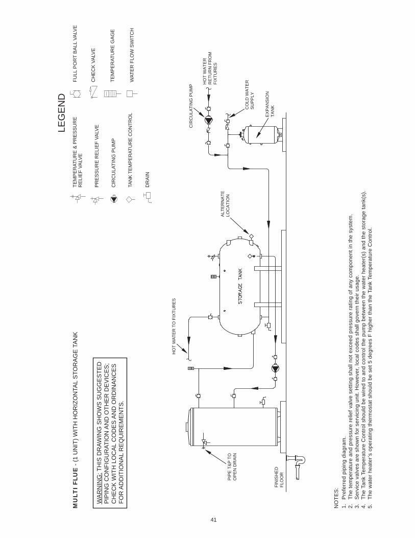
41
NO
TES
:1.
P
refe
rred
pip
ing
diag
ram
.2.
Th
e te
mpe
ratu
re a
nd p
ress
ure
relie
f val
ve s
ettin
g sh
all n
ot e
xcee
d pr
essu
re ra
ting
of a
ny c
ompo
nent
in th
e sy
stem
.3.
S
ervi
ce v
alve
s ar
e sh
own
for s
ervi
cing
uni
t. H
owev
er, l
ocal
cod
es s
hall
gove
rn th
eir u
sage
.4.
Th
e Ta
nk T
empe
ratu
re C
ontro
l sho
uld
be w
ired
to a
nd c
ontro
l the
pum
p be
twee
n th
e w
ater
hea
ter(
s) a
nd th
e st
orag
e ta
nk(s
).5.
Th
e w
ater
hea
ter’s
ope
ratin
g th
erm
osta
t sho
uld
be s
et 5
deg
rees
F h
ighe
r tha
n th
e Ta
nk T
empe
ratu
re C
ontro
l.
MU
LTI
FLU
E -
(1 U
NIT
) WIT
H H
OR
IZO
NTA
L S
TOR
AG
E T
AN
K
LEG
EN
DTE
MP
ER
ATU
RE
& P
RE
SS
UR
ER
ELI
EF
VALV
E
PR
ES
SU
RE
RE
LIE
F VA
LVE
CIR
CU
LATI
NG
PU
MP
TAN
K TE
MPE
RAT
UR
E C
ON
TRO
L
DR
AIN
FULL
PO
RT
BA
LL V
ALV
E
TEM
PE
RAT
UR
E G
AG
E
WAT
ER
FLO
W S
WIT
CH
CH
EC
K V
ALV
EW
AR
NIN
G: T
HIS
DR
AWIN
G S
HO
WS
SU
GG
ES
TED
PIP
ING
CO
NFI
GU
RAT
ION
AN
D O
THE
R D
EV
ICE
S;
CH
EC
K W
ITH
LO
CA
L C
OD
ES
AN
D O
RD
INA
NC
ES
FOR
AD
DIT
ION
AL
RE
QU
IRE
ME
NTS
.
FIN
ISH
ED
FLO
OR
HO
T W
ATE
R T
O F
IXTU
RE
S
CO
LD W
ATE
RS
UP
PLY
HO
T W
ATE
RR
ETU
RN
FR
OM
FI
XTU
RE
SA
LTE
RN
ATE
LOC
ATI
ON
CIR
CU
LATI
NG
PU
MP
EX
PA
NS
ION
TAN
K
PIP
E T
&P
TO
OP
EN
DR
AIN
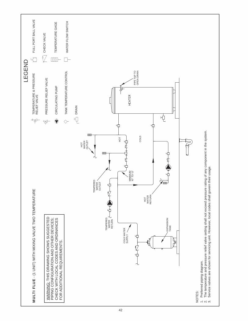
42
NO
TES
:1.
P
refe
rred
pip
ing
diag
ram
.2.
Th
e te
mpe
ratu
re a
nd p
ress
ure
relie
f val
ve s
ettin
g sh
all n
ot e
xcee
d pr
essu
re ra
ting
of a
ny c
ompo
nent
in th
e sy
stem
.3.
S
ervi
ce v
alve
s ar
e sh
own
for s
ervi
cing
uni
t. H
owev
er, l
ocal
cod
es s
hall
gove
rn th
eir u
sage
.4.
Th
e Ta
nk T
empe
ratu
re C
ontro
l sho
uld
be w
ired
to a
nd c
ontro
l the
pum
p be
twee
n th
e w
ater
hea
ter(
s) a
nd th
e st
orag
e ta
nk(s
).
MU
LTI
FLU
E -
(1 U
NIT
) WIT
H M
IXIN
G V
ALV
E T
WO
TE
MP
ER
ATU
RE
LEG
EN
DTE
MP
ER
ATU
RE
& P
RE
SS
UR
ER
ELI
EF
VALV
E
PR
ES
SU
RE
RE
LIE
F VA
LVE
CIR
CU
LATI
NG
PU
MP
TAN
K TE
MPE
RAT
UR
E C
ON
TRO
L
DR
AIN
FULL
PO
RT
BA
LL V
ALV
E
TEM
PE
RAT
UR
E G
AG
E
WAT
ER
FLO
W S
WIT
CH
CH
EC
K V
ALV
EW
AR
NIN
G: T
HIS
DR
AWIN
G S
HO
WS
SU
GG
ES
TED
PIP
ING
CO
NFI
GU
RAT
ION
AN
D O
THE
R D
EV
ICE
S;
CH
EC
K W
ITH
LO
CA
L C
OD
ES
AN
D O
RD
INA
NC
ES
FOR
AD
DIT
ION
AL
RE
QU
IRE
ME
NTS
.
TEM
PE
RE
DW
ATE
RR
ETU
RN
TEM
PE
RE
DW
ATE
RO
UTL
ET
HO
TW
ATE
RO
UTL
ET
HO
TW
ATE
RR
ETU
RN
CO
LD W
ATE
RS
UP
PLY
CO
LD
HO
T
EX
PA
NS
ION
TAN
K
PIP
E T
&P
TO
OP
EN
DR
AIN
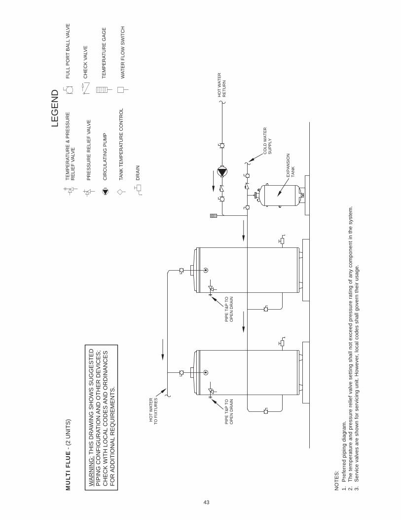
43
NO
TES
:1.
P
refe
rred
pip
ing
diag
ram
.2.
Th
e te
mpe
ratu
re a
nd p
ress
ure
relie
f val
ve s
ettin
g sh
all n
ot e
xcee
d pr
essu
re ra
ting
of a
ny c
ompo
nent
in th
e sy
stem
.3.
S
ervi
ce v
alve
s ar
e sh
own
for s
ervi
cing
uni
t. H
owev
er, l
ocal
cod
es s
hall
gove
rn th
eir u
sage
.4.
Th
e Ta
nk T
empe
ratu
re C
ontro
l sho
uld
be w
ired
to a
nd c
ontro
l the
pum
p be
twee
n th
e w
ater
hea
ter(
s) a
nd th
e st
orag
e ta
nk(s
).
MU
LTI
FLU
E -
(2 U
NIT
S)
LEG
EN
DTE
MP
ER
ATU
RE
& P
RE
SS
UR
ER
ELI
EF
VALV
E
PR
ES
SU
RE
RE
LIE
F VA
LVE
CIR
CU
LATI
NG
PU
MP
TAN
K TE
MPE
RAT
UR
E C
ON
TRO
L
DR
AIN
FULL
PO
RT
BA
LL V
ALV
E
TEM
PE
RAT
UR
E G
AG
E
WAT
ER
FLO
W S
WIT
CH
CH
EC
K V
ALV
EW
AR
NIN
G: T
HIS
DR
AWIN
G S
HO
WS
SU
GG
ES
TED
PIP
ING
CO
NFI
GU
RAT
ION
AN
D O
THE
R D
EV
ICE
S;
CH
EC
K W
ITH
LO
CA
L C
OD
ES
AN
D O
RD
INA
NC
ES
FOR
AD
DIT
ION
AL
RE
QU
IRE
ME
NTS
.
HO
T W
ATE
RTO
FIX
TUR
ES
CO
LD W
ATE
RS
UP
PLY
HO
T W
ATE
RR
ETU
RN
EX
PA
NS
ION
TAN
K
PIP
E T
&P
TO
OP
EN
DR
AIN
PIP
E T
&P
TO
OP
EN
DR
AIN
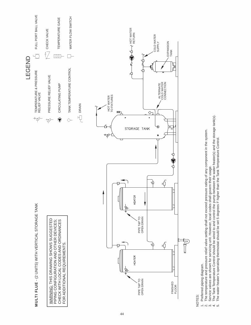
44
NO
TES
:1.
P
refe
rred
pip
ing
diag
ram
.2.
Th
e te
mpe
ratu
re a
nd p
ress
ure
relie
f val
ve s
ettin
g sh
all n
ot e
xcee
d pr
essu
re ra
ting
of a
ny c
ompo
nent
in th
e sy
stem
.3.
S
ervi
ce v
alve
s ar
e sh
own
for s
ervi
cing
uni
t. H
owev
er, l
ocal
cod
es s
hall
gove
rn th
eir u
sage
.4.
Th
e Ta
nk T
empe
ratu
re C
ontro
l sho
uld
be w
ired
to a
nd c
ontro
l the
pum
p be
twee
n th
e w
ater
hea
ter(
s) a
nd th
e st
orag
e ta
nk(s
).5.
Th
e w
ater
hea
ter’s
ope
ratin
g th
erm
osta
t sho
uld
be s
et 5
deg
rees
F h
ighe
r tha
n th
e Ta
nk T
empe
ratu
re C
ontro
l.
MU
LTI
FLU
E -
(2 U
NIT
S) W
ITH
VE
RTI
CA
L S
TOR
AG
E T
AN
K
LEG
EN
DTE
MP
ER
ATU
RE
& P
RE
SS
UR
ER
ELI
EF
VALV
E
PR
ES
SU
RE
RE
LIE
F VA
LVE
CIR
CU
LATI
NG
PU
MP
TAN
K TE
MPE
RAT
UR
E C
ON
TRO
L
DR
AIN
FULL
PO
RT
BA
LL V
ALV
E
TEM
PE
RAT
UR
E G
AG
E
WAT
ER
FLO
W S
WIT
CH
CH
EC
K V
ALV
EW
AR
NIN
G: T
HIS
DR
AWIN
G S
HO
WS
SU
GG
ES
TED
PIP
ING
CO
NFI
GU
RAT
ION
AN
D O
THE
R D
EV
ICE
S;
CH
EC
K W
ITH
LO
CA
L C
OD
ES
AN
D O
RD
INA
NC
ES
FOR
AD
DIT
ION
AL
RE
QU
IRE
ME
NTS
.
FIN
ISH
ED
FLO
OR
CO
LD W
ATE
RS
UP
PLY
HO
T W
ATE
RTO
FIX
TUR
ES
ALT
ER
NA
TEC
OLD
WA
TER
CO
NN
EC
TIO
N
HO
T W
ATE
RR
ETU
RN
EX
PA
NS
ION
TAN
K
PIP
E T
&P
TO
OP
EN
DR
AIN
PIP
E T
&P
TO
OP
EN
DR
AIN
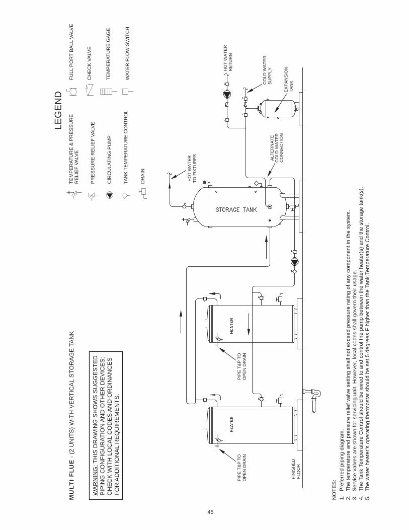
45
NO
TES
:1.
P
refe
rred
pip
ing
diag
ram
.2.
Th
e te
mpe
ratu
re a
nd p
ress
ure
relie
f val
ve s
ettin
g sh
all n
ot e
xcee
d pr
essu
re ra
ting
of a
ny c
ompo
nent
in th
e sy
stem
.3.
S
ervi
ce v
alve
s ar
e sh
own
for s
ervi
cing
uni
t. H
owev
er, l
ocal
cod
es s
hall
gove
rn th
eir u
sage
.4.
Th
e Ta
nk T
empe
ratu
re C
ontro
l sho
uld
be w
ired
to a
nd c
ontro
l the
pum
p be
twee
n th
e w
ater
hea
ter(
s) a
nd th
e st
orag
e ta
nk(s
).5.
Th
e w
ater
hea
ter’s
ope
ratin
g th
erm
osta
t sho
uld
be s
et 5
deg
rees
F h
ighe
r tha
n th
e Ta
nk T
empe
ratu
re C
ontro
l.
MU
LTI
FLU
E -
(2 U
NIT
S) W
ITH
VE
RTI
CA
L S
TOR
AG
E T
AN
K
LEG
EN
DTE
MP
ER
ATU
RE
& P
RE
SS
UR
ER
ELI
EF
VALV
E
PR
ES
SU
RE
RE
LIE
F VA
LVE
CIR
CU
LATI
NG
PU
MP
TAN
K TE
MPE
RAT
UR
E C
ON
TRO
L
DR
AIN
FULL
PO
RT
BA
LL V
ALV
E
TEM
PE
RAT
UR
E G
AG
E
WAT
ER
FLO
W S
WIT
CH
CH
EC
K V
ALV
EW
AR
NIN
G: T
HIS
DR
AWIN
G S
HO
WS
SU
GG
ES
TED
PIP
ING
CO
NFI
GU
RAT
ION
AN
D O
THE
R D
EV
ICE
S;
CH
EC
K W
ITH
LO
CA
L C
OD
ES
AN
D O
RD
INA
NC
ES
FOR
AD
DIT
ION
AL
RE
QU
IRE
ME
NTS
.
FIN
ISH
ED
FLO
OR
CO
LD W
ATE
RS
UP
PLY
HO
T W
ATE
RTO
FIX
TUR
ES
ALT
ER
NA
TEC
OLD
WA
TER
CO
NN
EC
TIO
N
HO
T W
ATE
RR
ETU
RN
EX
PA
NS
ION
TAN
K
PIP
E T
&P
TO
OP
EN
DR
AIN
PIP
E T
&P
TO
OP
EN
DR
AIN
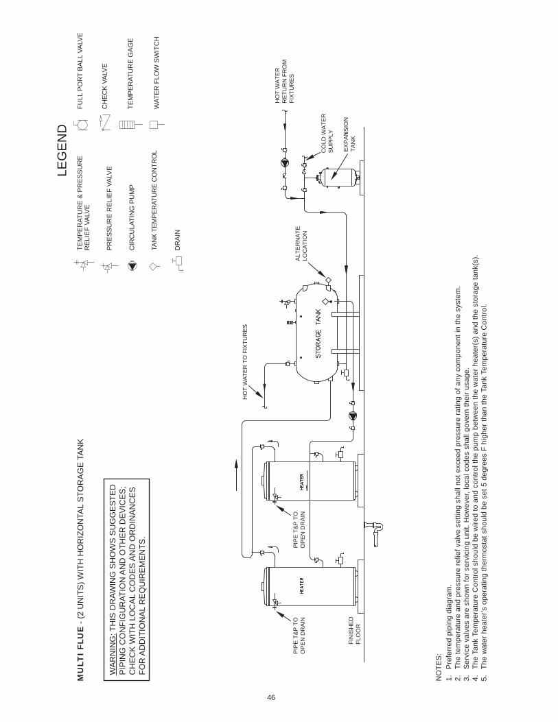
46
NO
TES
:1.
P
refe
rred
pip
ing
diag
ram
.2.
Th
e te
mpe
ratu
re a
nd p
ress
ure
relie
f val
ve s
ettin
g sh
all n
ot e
xcee
d pr
essu
re ra
ting
of a
ny c
ompo
nent
in th
e sy
stem
.3.
S
ervi
ce v
alve
s ar
e sh
own
for s
ervi
cing
uni
t. H
owev
er, l
ocal
cod
es s
hall
gove
rn th
eir u
sage
.4.
Th
e Ta
nk T
empe
ratu
re C
ontro
l sho
uld
be w
ired
to a
nd c
ontro
l the
pum
p be
twee
n th
e w
ater
hea
ter(
s) a
nd th
e st
orag
e ta
nk(s
).5.
Th
e w
ater
hea
ter’s
ope
ratin
g th
erm
osta
t sho
uld
be s
et 5
deg
rees
F h
ighe
r tha
n th
e Ta
nk T
empe
ratu
re C
ontro
l.
MU
LTI
FLU
E -
(2 U
NIT
S) W
ITH
HO
RIZ
ON
TAL
STO
RA
GE
TA
NK
LEG
EN
DTE
MP
ER
ATU
RE
& P
RE
SS
UR
ER
ELI
EF
VALV
E
PR
ES
SU
RE
RE
LIE
F VA
LVE
CIR
CU
LATI
NG
PU
MP
TAN
K TE
MPE
RAT
UR
E C
ON
TRO
L
DR
AIN
FULL
PO
RT
BA
LL V
ALV
E
TEM
PE
RAT
UR
E G
AG
E
WAT
ER
FLO
W S
WIT
CH
CH
EC
K V
ALV
EW
AR
NIN
G: T
HIS
DR
AWIN
G S
HO
WS
SU
GG
ES
TED
PIP
ING
CO
NFI
GU
RAT
ION
AN
D O
THE
R D
EV
ICE
S;
CH
EC
K W
ITH
LO
CA
L C
OD
ES
AN
D O
RD
INA
NC
ES
FOR
AD
DIT
ION
AL
RE
QU
IRE
ME
NTS
.
FIN
ISH
ED
FLO
OR
HO
T W
ATE
R T
O F
IXTU
RE
S
CO
LD W
ATE
RS
UP
PLY
HO
T W
ATE
RR
ETU
RN
FR
OM
FI
XTU
RE
SA
LTE
RN
ATE
LOC
ATI
ON
EX
PA
NS
ION
TAN
K
PIP
E T
&P
TO
OP
EN
DR
AIN
PIP
E T
&P
TO
OP
EN
DR
AIN
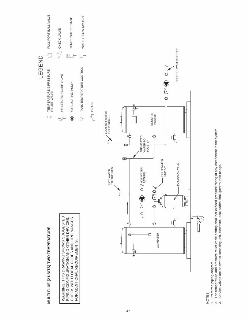
47
NO
TES
:1.
P
refe
rred
pip
ing
diag
ram
.2.
Th
e te
mpe
ratu
re a
nd p
ress
ure
relie
f val
ve s
ettin
g sh
all n
ot e
xcee
d pr
essu
re ra
ting
of a
ny c
ompo
nent
in th
e sy
stem
.3.
S
ervi
ce v
alve
s ar
e sh
own
for s
ervi
cing
uni
t. H
owev
er, l
ocal
cod
es s
hall
gove
rn th
eir u
sage
.
MU
LTI F
LUE
(2 U
NIT
S) T
WO
TEM
PER
ATU
RE
LEG
EN
DTE
MP
ER
ATU
RE
& P
RE
SS
UR
ER
ELI
EF
VALV
E
PR
ES
SU
RE
RE
LIE
F VA
LVE
CIR
CU
LATI
NG
PU
MP
TAN
K TE
MPE
RAT
UR
E C
ON
TRO
L
DR
AIN
FULL
PO
RT
BA
LL V
ALV
E
TEM
PE
RAT
UR
E G
AG
E
WAT
ER
FLO
W S
WIT
CH
CH
EC
K V
ALV
EW
AR
NIN
G: T
HIS
DR
AWIN
G S
HO
WS
SU
GG
ES
TED
PIP
ING
CO
NFI
GU
RAT
ION
AN
D O
THE
R D
EV
ICE
S;
CH
EC
K W
ITH
LO
CA
L C
OD
ES
AN
D O
RD
INA
NC
ES
FOR
AD
DIT
ION
AL
RE
QU
IRE
ME
NTS
.
BO
OS
TER
WA
TER
RE
TUR
N
PR
E-H
EA
TED
WA
TER
TO
B
OO
STE
R
BO
OS
TER
WA
TER
TO F
IXTU
RE
SH
OT
WA
TER
TO F
IXTU
RE
S
EX
PA
NS
ION
TA
NK
HO
T W
ATE
RR
ETU
RN
CO
LD W
ATE
RS
UP
PLY
1st H
EA
TER
BO
OS
TER
HE
ATE
R
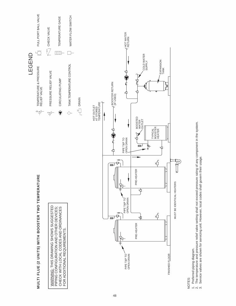
48
NO
TES
:1.
P
refe
rred
pip
ing
diag
ram
.2.
Th
e te
mpe
ratu
re a
nd p
ress
ure
relie
f val
ve s
ettin
g sh
all n
ot e
xcee
d pr
essu
re ra
ting
of a
ny c
ompo
nent
in th
e sy
stem
.3.
S
ervi
ce v
alve
s ar
e sh
own
for s
ervi
cing
uni
t. H
owev
er, l
ocal
cod
es s
hall
gove
rn th
eir u
sage
.
MU
LTI
FLU
E (
2 U
NIT
S)
WIT
H B
OO
ST
ER
TW
O T
EM
PE
RA
TU
RE
LEG
EN
DTE
MP
ER
ATU
RE
& P
RE
SS
UR
ER
ELI
EF
VALV
E
PR
ES
SU
RE
RE
LIE
F VA
LVE
CIR
CU
LATI
NG
PU
MP
TAN
K TE
MPE
RAT
UR
E C
ON
TRO
L
DR
AIN
FULL
PO
RT
BA
LL V
ALV
E
TEM
PE
RAT
UR
E G
AG
E
WAT
ER
FLO
W S
WIT
CH
CH
EC
K V
ALV
EW
AR
NIN
G: T
HIS
DR
AWIN
G S
HO
WS
SU
GG
ES
TED
PIP
ING
CO
NFI
GU
RAT
ION
AN
D O
THE
R D
EV
ICE
S;
CH
EC
K W
ITH
LO
CA
L C
OD
ES
AN
D O
RD
INA
NC
ES
FOR
AD
DIT
ION
AL
RE
QU
IRE
ME
NTS
.
EX
PA
NS
ION
TAN
K
BO
OS
TED
WA
TER
OU
TLE
T
TYP
ICA
LB
OO
STE
RH
EA
TER
PR
E-H
EA
TER
PR
E-H
EA
TER
MU
ST
BE
IDE
NTI
CA
L H
EA
TER
S
FIN
ISH
ED
FLO
OR
CO
LD W
ATE
RS
UP
PLY
HO
T O
UTL
ET
AT
STO
RE
DTE
MP
ER
ATU
RE
BO
OS
TER
RE
TUR
N(IF
US
ED
)
HO
T W
ATE
RR
ETU
RN
PIP
E T
&P
TO
OP
EN
DR
AIN
PIP
E T
&P
TO
OP
EN
DR
AIN
PIP
E T
&P
TO
OP
EN
DR
AIN
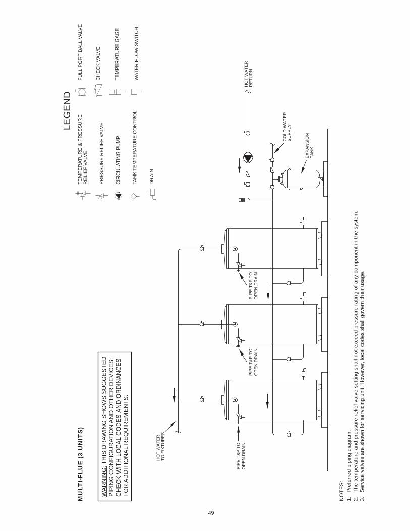
49
NO
TES
:1.
P
refe
rred
pip
ing
diag
ram
.2.
Th
e te
mpe
ratu
re a
nd p
ress
ure
relie
f val
ve s
ettin
g sh
all n
ot e
xcee
d pr
essu
re ra
ting
of a
ny c
ompo
nent
in th
e sy
stem
.3.
S
ervi
ce v
alve
s ar
e sh
own
for s
ervi
cing
uni
t. H
owev
er, l
ocal
cod
es s
hall
gove
rn th
eir u
sage
.
MU
LTI-
FLU
E (
3 U
NIT
S)
LEG
EN
DTE
MP
ER
ATU
RE
& P
RE
SS
UR
ER
ELI
EF
VALV
E
PR
ES
SU
RE
RE
LIE
F VA
LVE
CIR
CU
LATI
NG
PU
MP
TAN
K TE
MPE
RAT
UR
E C
ON
TRO
L
DR
AIN
FULL
PO
RT
BA
LL V
ALV
E
TEM
PE
RAT
UR
E G
AG
E
WAT
ER
FLO
W S
WIT
CH
CH
EC
K V
ALV
EW
AR
NIN
G: T
HIS
DR
AWIN
G S
HO
WS
SU
GG
ES
TED
PIP
ING
CO
NFI
GU
RAT
ION
AN
D O
THE
R D
EV
ICE
S;
CH
EC
K W
ITH
LO
CA
L C
OD
ES
AN
D O
RD
INA
NC
ES
FOR
AD
DIT
ION
AL
RE
QU
IRE
ME
NTS
.
HO
T W
ATE
RTO
FIX
TUR
ES
HO
T W
ATE
RR
ETU
RN
CO
LD W
ATE
RS
UP
PLY
EX
PA
NS
ION
TAN
K
PIP
E T
&P
TO
OP
EN
DR
AIN
PIP
E T
&P
TO
OP
EN
DR
AIN
PIP
E T
&P
TO
OP
EN
DR
AIN
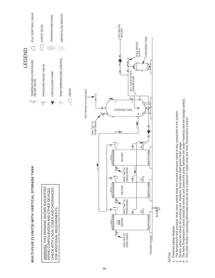
50
NO
TES
:1.
P
refe
rred
pip
ing
diag
ram
.2.
Th
e te
mpe
ratu
re a
nd p
ress
ure
relie
f val
ve s
ettin
g sh
all n
ot e
xcee
d pr
essu
re ra
ting
of a
ny c
ompo
nent
in th
e sy
stem
.3.
S
ervi
ce v
alve
s ar
e sh
own
for s
ervi
cing
uni
t. H
owev
er, l
ocal
cod
es s
hall
gove
rn th
eir u
sage
.4.
Th
e Ta
nk T
empe
ratu
re C
ontro
l sho
uld
be w
ired
to a
nd c
ontro
l the
pum
p be
twee
n th
e w
ater
hea
ter(
s) a
nd th
e st
orag
e ta
nk(s
).5.
Th
e w
ater
hea
ter’s
ope
ratin
g th
erm
osta
t sho
uld
be s
et 5
deg
rees
F h
ighe
r tha
n th
e Ta
nk T
empe
ratu
re C
ontro
l.
MU
LTI-
FLU
E (
3 U
NIT
S)
WIT
H V
ER
TIC
AL
STO
RA
GE
TA
NK
LEG
EN
DTE
MP
ER
ATU
RE
& P
RE
SS
UR
ER
ELI
EF
VALV
E
PR
ES
SU
RE
RE
LIE
F VA
LVE
CIR
CU
LATI
NG
PU
MP
TAN
K TE
MPE
RAT
UR
E C
ON
TRO
L
DR
AIN
FULL
PO
RT
BA
LL V
ALV
E
TEM
PE
RAT
UR
E G
AG
E
WAT
ER
FLO
W S
WIT
CH
CH
EC
K V
ALV
EW
AR
NIN
G: T
HIS
DR
AWIN
G S
HO
WS
SU
GG
ES
TED
PIP
ING
CO
NFI
GU
RAT
ION
AN
D O
THE
R D
EV
ICE
S;
CH
EC
K W
ITH
LO
CA
L C
OD
ES
AN
D O
RD
INA
NC
ES
FOR
AD
DIT
ION
AL
RE
QU
IRE
ME
NTS
.
TO F
IXTU
RE
S
HO
T W
ATE
RR
ETU
RN
ALT
. CO
LD W
ATE
RC
ON
NE
CTI
ON
AOSSTORAGE TANK
HO
T W
ATE
R
HE
ATE
RH
EA
TER
HE
ATE
R
FIN
ISH
ED
FLO
OR
CO
LD W
ATE
RS
UP
PLY
EX
PA
NS
ION
TA
NK
PIP
E T
&P
TO
OP
EN
DR
AIN
PIP
E T
&P
TO
OP
EN
DR
AIN
PIP
E T
&P
TO
OP
EN
DR
AIN
PIP
E T
&P
TO
OP
EN
DR
AIN
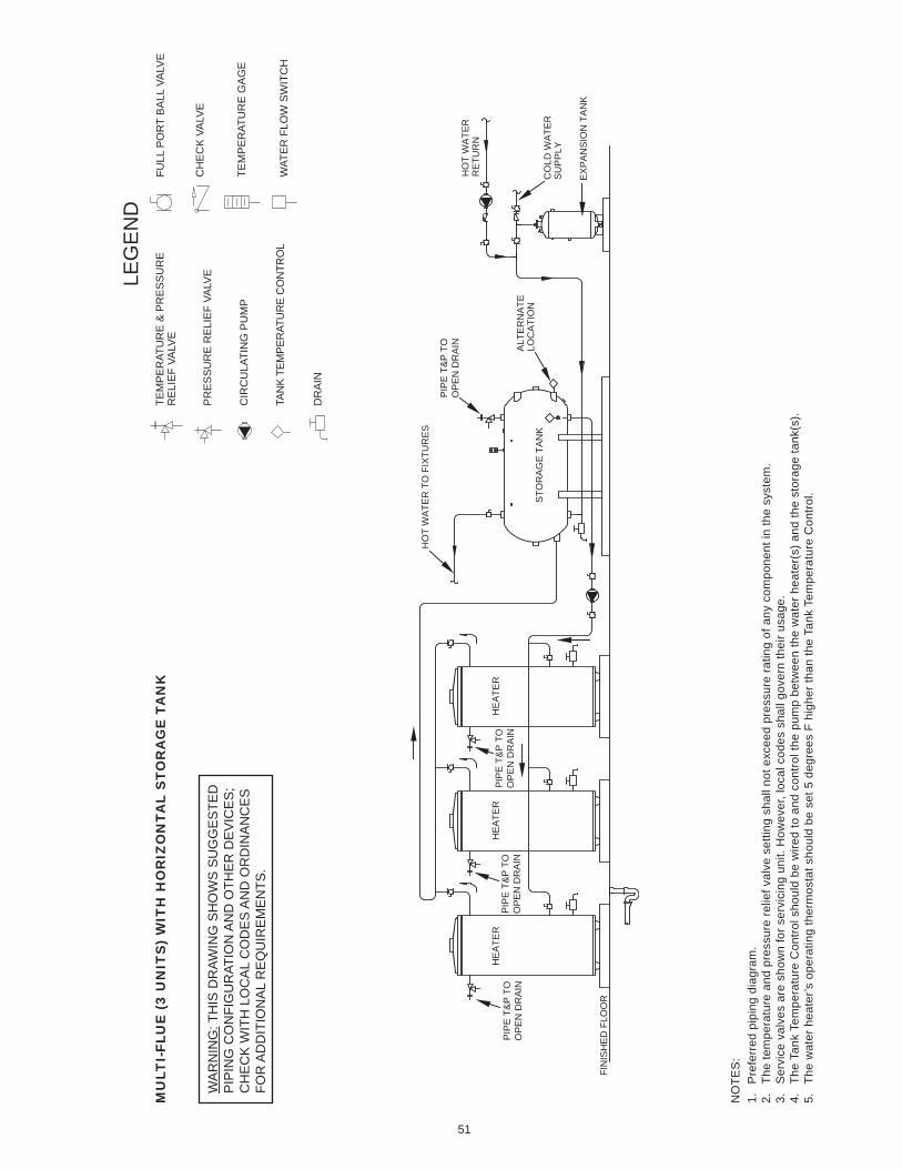
51
NO
TES
:1.
P
refe
rred
pip
ing
diag
ram
.2.
Th
e te
mpe
ratu
re a
nd p
ress
ure
relie
f val
ve s
ettin
g sh
all n
ot e
xcee
d pr
essu
re ra
ting
of a
ny c
ompo
nent
in th
e sy
stem
.3.
S
ervi
ce v
alve
s ar
e sh
own
for s
ervi
cing
uni
t. H
owev
er, l
ocal
cod
es s
hall
gove
rn th
eir u
sage
.4.
Th
e Ta
nk T
empe
ratu
re C
ontro
l sho
uld
be w
ired
to a
nd c
ontro
l the
pum
p be
twee
n th
e w
ater
hea
ter(
s) a
nd th
e st
orag
e ta
nk(s
).5.
Th
e w
ater
hea
ter’s
ope
ratin
g th
erm
osta
t sho
uld
be s
et 5
deg
rees
F h
ighe
r tha
n th
e Ta
nk T
empe
ratu
re C
ontro
l.
MU
LTI-
FLU
E (
3 U
NIT
S)
WIT
H H
OR
IZO
NTA
L S
TOR
AG
E T
AN
K
LEG
EN
DTE
MP
ER
ATU
RE
& P
RE
SS
UR
ER
ELI
EF
VALV
E
PR
ES
SU
RE
RE
LIE
F VA
LVE
CIR
CU
LATI
NG
PU
MP
TAN
K TE
MPE
RAT
UR
E C
ON
TRO
L
DR
AIN
FULL
PO
RT
BA
LL V
ALV
E
TEM
PE
RAT
UR
E G
AG
E
WAT
ER
FLO
W S
WIT
CH
CH
EC
K V
ALV
EW
AR
NIN
G: T
HIS
DR
AWIN
G S
HO
WS
SU
GG
ES
TED
PIP
ING
CO
NFI
GU
RAT
ION
AN
D O
THE
R D
EV
ICE
S;
CH
EC
K W
ITH
LO
CA
L C
OD
ES
AN
D O
RD
INA
NC
ES
FOR
AD
DIT
ION
AL
RE
QU
IRE
ME
NTS
.
HO
T W
ATE
RR
ETU
RN
ALT
ER
NA
TELO
CA
TIO
N
HO
T W
ATE
R T
O F
IXTU
RE
S
AO
SS
TOR
AG
E T
AN
K
HE
ATE
RH
EA
TER
HE
ATE
R
FIN
ISH
ED
FLO
OR
EX
PA
NS
ION
TA
NK
CO
LD W
ATE
RS
UP
PLY
PIP
E T
&P
TO
OP
EN
DR
AIN
PIP
E T
&P
TO
OP
EN
DR
AIN
PIP
E T
&P
TO
OP
EN
DR
AIN
PIP
E T
&P
TO
OP
EN
DR
AIN
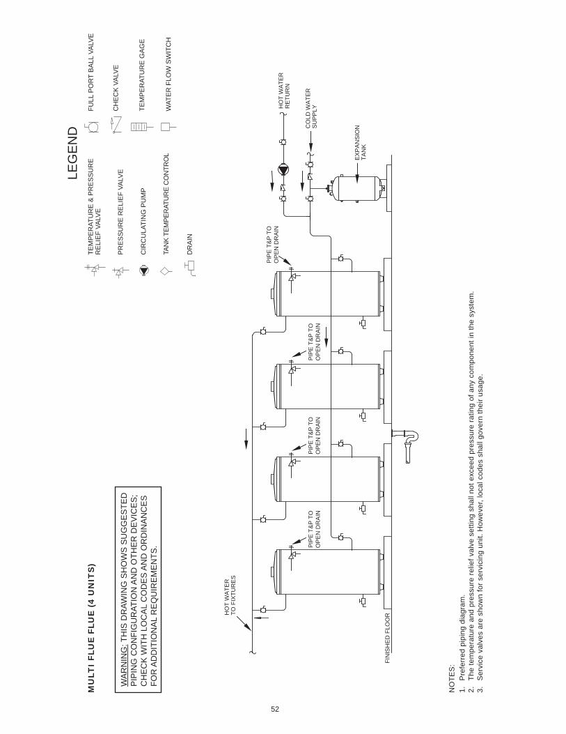
52
NO
TES
:1.
P
refe
rred
pip
ing
diag
ram
.2.
Th
e te
mpe
ratu
re a
nd p
ress
ure
relie
f val
ve s
ettin
g sh
all n
ot e
xcee
d pr
essu
re ra
ting
of a
ny c
ompo
nent
in th
e sy
stem
.3.
S
ervi
ce v
alve
s ar
e sh
own
for s
ervi
cing
uni
t. H
owev
er, l
ocal
cod
es s
hall
gove
rn th
eir u
sage
.
MU
LTI
FLU
E F
LUE
(4
UN
ITS
)
LEG
EN
DTE
MP
ER
ATU
RE
& P
RE
SS
UR
ER
ELI
EF
VALV
E
PR
ES
SU
RE
RE
LIE
F VA
LVE
CIR
CU
LATI
NG
PU
MP
TAN
K TE
MPE
RAT
UR
E C
ON
TRO
L
DR
AIN
FULL
PO
RT
BA
LL V
ALV
E
TEM
PE
RAT
UR
E G
AG
E
WAT
ER
FLO
W S
WIT
CH
CH
EC
K V
ALV
EW
AR
NIN
G: T
HIS
DR
AWIN
G S
HO
WS
SU
GG
ES
TED
PIP
ING
CO
NFI
GU
RAT
ION
AN
D O
THE
R D
EV
ICE
S;
CH
EC
K W
ITH
LO
CA
L C
OD
ES
AN
D O
RD
INA
NC
ES
FOR
AD
DIT
ION
AL
RE
QU
IRE
ME
NTS
.
EX
PA
NS
ION
TAN
K
CO
LD W
ATE
RS
UP
PLY
HO
T W
ATE
RTO
FIX
TUR
ES
FIN
ISH
ED
FLO
OR
HO
T W
ATE
RR
ETU
RN
PIP
E T
&P
TO
OP
EN
DR
AIN
PIP
E T
&P
TO
OP
EN
DR
AIN
PIP
E T
&P
TO
OP
EN
DR
AIN
PIP
E T
&P
TO
OP
EN
DR
AIN
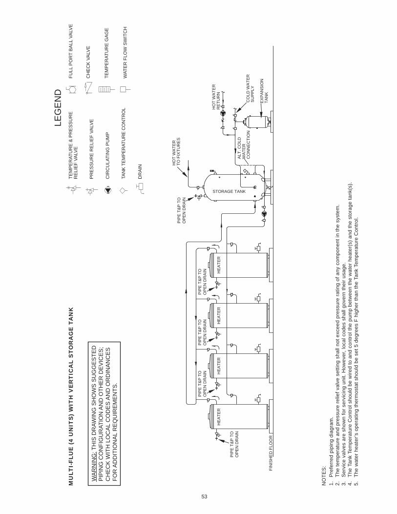
53
NO
TES
:1.
P
refe
rred
pip
ing
diag
ram
.2.
Th
e te
mpe
ratu
re a
nd p
ress
ure
relie
f val
ve s
ettin
g sh
all n
ot e
xcee
d pr
essu
re ra
ting
of a
ny c
ompo
nent
in th
e sy
stem
.3.
S
ervi
ce v
alve
s ar
e sh
own
for s
ervi
cing
uni
t. H
owev
er, l
ocal
cod
es s
hall
gove
rn th
eir u
sage
.4.
Th
e Ta
nk T
empe
ratu
re C
ontro
l sho
uld
be w
ired
to a
nd c
ontro
l the
pum
p be
twee
n th
e w
ater
hea
ter(
s) a
nd th
e st
orag
e ta
nk(s
).5.
Th
e w
ater
hea
ter’s
ope
ratin
g th
erm
osta
t sho
uld
be s
et 5
deg
rees
F h
ighe
r tha
n th
e Ta
nk T
empe
ratu
re C
ontro
l.
MU
LTI-
FLU
E (
4 U
NIT
S)
WIT
H V
ER
TIC
AL
STO
RA
GE
TA
NK
LEG
EN
DTE
MP
ER
ATU
RE
& P
RE
SS
UR
ER
ELI
EF
VALV
E
PR
ES
SU
RE
RE
LIE
F VA
LVE
CIR
CU
LATI
NG
PU
MP
TAN
K TE
MPE
RAT
UR
E C
ON
TRO
L
DR
AIN
FULL
PO
RT
BA
LL V
ALV
E
TEM
PE
RAT
UR
E G
AG
E
WAT
ER
FLO
W S
WIT
CH
CH
EC
K V
ALV
EW
AR
NIN
G: T
HIS
DR
AWIN
G S
HO
WS
SU
GG
ES
TED
PIP
ING
CO
NFI
GU
RAT
ION
AN
D O
THE
R D
EV
ICE
S;
CH
EC
K W
ITH
LO
CA
L C
OD
ES
AN
D O
RD
INA
NC
ES
FOR
AD
DIT
ION
AL
RE
QU
IRE
ME
NTS
.
HO
T W
ATE
RTO
FIX
TUR
ES
HO
T W
ATE
RR
ETU
RN
CO
LD W
ATE
RS
UP
PLY
EX
PA
NS
ION
TAN
K
ALT
. CO
LDW
ATE
RC
ON
NE
CTI
ON
AOSSTORAGE TANK
HE
ATE
RH
EA
TER
HE
ATE
RH
EA
TER
FIN
ISH
ED
FLO
OR
PIP
E T
&P
TO
OP
EN
DR
AIN
PIP
E T
&P
TO
OP
EN
DR
AIN
PIP
E T
&P
TO
OP
EN
DR
AIN
PIP
E T
&P
TO
OP
EN
DR
AIN
PIP
E T
&P
TO
OP
EN
DR
AIN
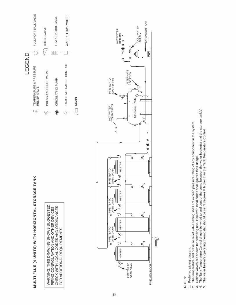
54
NO
TES
:1.
P
refe
rred
pip
ing
diag
ram
.2.
Th
e te
mpe
ratu
re a
nd p
ress
ure
relie
f val
ve s
ettin
g sh
all n
ot e
xcee
d pr
essu
re ra
ting
of a
ny c
ompo
nent
in th
e sy
stem
.3.
S
ervi
ce v
alve
s ar
e sh
own
for s
ervi
cing
uni
t. H
owev
er, l
ocal
cod
es s
hall
gove
rn th
eir u
sage
.4.
Th
e Ta
nk T
empe
ratu
re C
ontro
l sho
uld
be w
ired
to a
nd c
ontro
l the
pum
p be
twee
n th
e w
ater
hea
ter(
s) a
nd th
e st
orag
e ta
nk(s
).5.
Th
e w
ater
hea
ter’s
ope
ratin
g th
erm
osta
t sho
uld
be s
et 5
deg
rees
F h
ighe
r tha
n th
e Ta
nk T
empe
ratu
re C
ontro
l.
MU
LTI-
FLU
E (
4 U
NIT
S)
WIT
H H
OR
IZO
NTA
L S
TOR
AG
E T
AN
K
LEG
EN
DTE
MP
ER
ATU
RE
& P
RE
SS
UR
ER
ELI
EF
VALV
E
PR
ES
SU
RE
RE
LIE
F VA
LVE
CIR
CU
LATI
NG
PU
MP
TAN
K TE
MPE
RAT
UR
E C
ON
TRO
L
DR
AIN
FULL
PO
RT
BA
LL V
ALV
E
TEM
PE
RAT
UR
E G
AG
E
WAT
ER
FLO
W S
WIT
CH
CH
EC
K V
ALV
EW
AR
NIN
G: T
HIS
DR
AWIN
G S
HO
WS
SU
GG
ES
TED
PIP
ING
CO
NFI
GU
RAT
ION
AN
D O
THE
R D
EV
ICE
S;
CH
EC
K W
ITH
LO
CA
L C
OD
ES
AN
D O
RD
INA
NC
ES
FOR
AD
DIT
ION
AL
RE
QU
IRE
ME
NTS
.
HO
T W
ATE
RTO
FIX
TUR
ES
HO
T W
ATE
RR
ETU
RN
CO
LD W
ATE
RS
UP
PLY
ALT
ER
NA
TELO
CA
TIO
NA
OS
STO
RA
GE
TA
NK
HE
ATE
RH
EA
TER
HE
ATE
RH
EA
TER
FIN
ISH
ED
FLO
OR
EX
PA
NS
ION
TA
NK
PIP
E T
&P
TO
OP
EN
DR
AIN
PIP
E T
&P
TO
OP
EN
DR
AIN
PIP
E T
&P
TO
OP
EN
DR
AIN
PIP
E T
&P
TO
OP
EN
DR
AIN
PIP
E T
&P
TO
OP
EN
DR
AIN
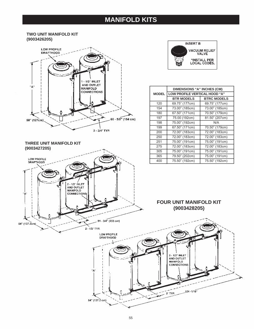
55
manifold kits
two unit manifold kit(9003426205)
three unit manifold kit(9003427205)
four unit manifold kit(9003428205)
dimensions “a” inches (cm) model low profile Vertical hood “a” Btr models Btrc models 120 69.75” (177cm) 69.75” (177cm) 154 73.00” (185cm) 73.00” (185cm) 180 67.50” (171cm) 70.50” (179cm) 197 75.00 (192cm) 81.50” (207cm) 198 75.00” (192cm) N/A 199 67.50” (171cm) 70.50” (179cm) 200 72.00” (183cm) 72.00” (183cm) 250 72.00” (183cm) 72.00” (183cm) 251 75.00” (191cm) 75.00” (191cm) 275 72.00” (183cm) 72.00” (183cm) 305 75.00” (191cm) 75.00” (191cm) 365 79.50” (202cm) 75.00” (191cm) 400 75.50” (192cm) 75.50” (192cm)

notes
56

notes
57

notes
58
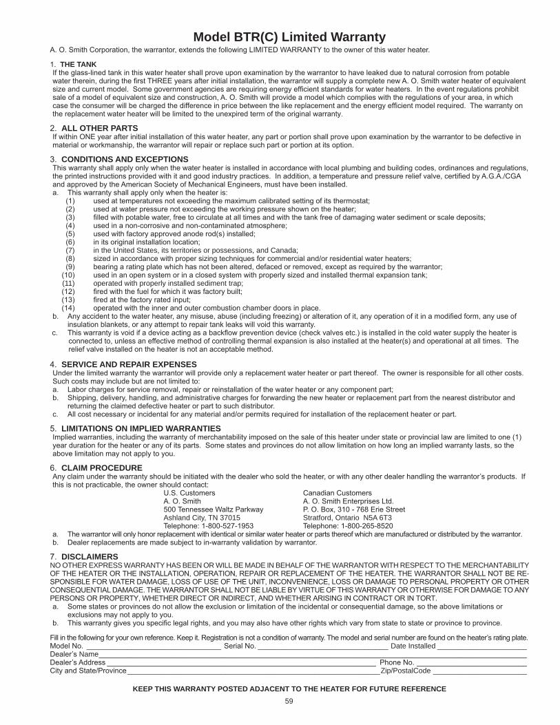
model Btr(c) limited warrantyA. O. Smith Corporation, the warrantor, extends the following LIMITeD WARRANTY to the owner of this water heater.
1. the tankIf the glass-lined tank in this water heater shall prove upon examination by the warrantor to have leaked due to natural corrosion from potable water therein, during the first THRee years after initial installation, the warrantor will supply a complete new A. O. Smith water heater of equivalent size and current model. Some government agencies are requiring energy efficient standards for water heaters. In the event regulations prohibit sale of a model of equivalent size and construction, A. O. Smith will provide a model which complies with the regulations of your area, in which case the consumer will be charged the difference in price between the like replacement and the energy efficient model required. The warranty on the replacement water heater will be limited to the unexpired term of the original warranty.
2. all other partsIf within ONe year after initial installation of this water heater, any part or portion shall prove upon examination by the warrantor to be defective in material or workmanship, the warrantor will repair or replace such part or portion at its option.
3. conditions and exceptionsThis warranty shall apply only when the water heater is installed in accordance with local plumbing and building codes, ordinances and regulations, the printed instructions provided with it and good industry practices. In addition, a temperature and pressure relief valve, certified by A.G.A./CGA and approved by the American Society of Mechanical engineers, must have been installed.
a. This warranty shall apply only when the heater is: (1) used at temperatures not exceeding the maximum calibrated setting of its thermostat; (2) used at water pressure not exceeding the working pressure shown on the heater; (3) filled with potable water, free to circulate at all times and with the tank free of damaging water sediment or scale deposits; (4) used in a non-corrosive and non-contaminated atmosphere; (5) used with factory approved anode rod(s) installed; (6) in its original installation location; (7) in the United states, its territories or possessions, and Canada; (8) sized in accordance with proper sizing techniques for commercial and/or residential water heaters; (9) bearing a rating plate which has not been altered, defaced or removed, except as required by the warrantor; (10) used in an open system or in a closed system with properly sized and installed thermal expansion tank; (11) operated with properly installed sediment trap; (12) fired with the fuel for which it was factory built; (13) fired at the factory rated input; (14) operated with the inner and outer combustion chamber doors in place. b. Any accident to the water heater, any misuse, abuse (including freezing) or alteration of it, any operation of it in a modified form, any use of insulation blankets, or any attempt to repair tank leaks will void this warranty. c. This warranty is void if a device acting as a backflow prevention device (check valves etc.) is installed in the cold water supply the heater is
connected to, unless an effective method of controlling thermal expansion is also installed at the heater(s) and operational at all times. The relief valve installed on the heater is not an acceptable method.
4. serVice and repair expensesUnder the limited warranty the warrantor will provide only a replacement water heater or part thereof. The owner is responsible for all other costs. Such costs may include but are not limited to:
a. Labor charges for service removal, repair or reinstallation of the water heater or any component part; b. Shipping, delivery, handling, and administrative charges for forwarding the new heater or replacement part from the nearest distributor and returning the claimed defective heater or part to such distributor. c. All cost necessary or incidental for any material and/or permits required for installation of the replacement heater or part.
5. limitations on implied warrantiesImplied warranties, including the warranty of merchantability imposed on the sale of this heater under state or provincial law are limited to one (1) year duration for the heater or any of its parts. Some states and provinces do not allow limitation on how long an implied warranty lasts, so the above limitation may not apply to you.
6. claim procedureAny claim under the warranty should be initiated with the dealer who sold the heater, or with any other dealer handling the warrantor’s products. If this is not practicable, the owner should contact:
U.S. Customers Canadian Customers A. O. Smith A. O. Smith enterprises Ltd. 500 Tennessee Waltz Parkway P. O. box, 310 - 768 erie Street Ashland City, TN 37015 stratford, ontario N5A 6T3 Telephone: 1-800-527-1953 Telephone: 1-800-265-8520 a. The warrantor will only honor replacement with identical or similar water heater or parts thereof which are manufactured or distributed by the warrantor.b. Dealer replacements are made subject to in-warranty validation by warrantor.
7. disclaimersNo oTHER EXPREss WARRANTy HAs BEEN oR WIll BE mADE IN BEHAlf of THE WARRANToR WITH REsPECT To THE mERCHANTABIlITy OF THe HeATeR OR THe INSTALLATION, OPeRATION, RePAIR OR RePLACeMeNT OF THe HeATeR. THe WARRANTOR SHALL NOT be Re-SPONSIbLe FOR WATeR DAMAGe, LOSS OF USe OF THe UNIT, INCONVeNIeNCe, LOSS OR DAMAGe TO PeRSONAL PROPeRTY OR OTHeR CONSeQUeNTIAL DAMAGe. THe WARRANTOR SHALL NOT be LIAbLe bY VIRTUe OF THIS WARRANTY OR OTHeRWISe FOR DAMAGe TO ANY PeRSONS OR PROPeRTY, WHeTHeR DIReCT OR INDIReCT, AND WHeTHeR ARISING IN CONTRACT OR IN TORT.a. Some states or provinces do not allow the exclusion or limitation of the incidental or consequential damage, so the above limitations or exclusions may not apply to you.b. This warranty gives you specific legal rights, and you may also have other rights which vary from state to state or province to province.
Fill in the following for your own reference. Keep it. Registration is not a condition of warranty. The model and serial number are found on the heater’s rating plate.Model No. _________________________________ Serial No. ________________________________ Date Installed ______________________Dealer’s Name _________________________________________________________________________________________________________Dealer’s Address __________________________________________________________________ Phone No. ___________________________City and State/Province ______________________________________________________________zip/PostalCode _______________________
keep this warranty posted adjacent to the heater for future reference59

500 Tennessee Waltz Parkway, Ashland City, TN 37015Technical Support: 800-527-1953 • Parts: 800-433-2545
www.hotwater.com
Copyright © 2012 A. O. Smith, All rights reserved.


![Shobowale, A.O. PMP Certification[1]](https://img.pdfslide.us/doc/110x75/58f9b9fe1a28ab195b8b45a7/shobowale-ao-pmp-certification1.jpg)