Embed Size (px)
Citation preview
AO Controls: Status and IssuesAO Controls: Status and Issues
Erik Johansson, Jimmy Johnson,Erik Johansson, Jimmy Johnson,Doug Morrison and Ed WetherellDoug Morrison and Ed Wetherell
NGAO PD Team Meeting #6NGAO PD Team Meeting #6Thursday, March 19, 2009Thursday, March 19, 2009
2
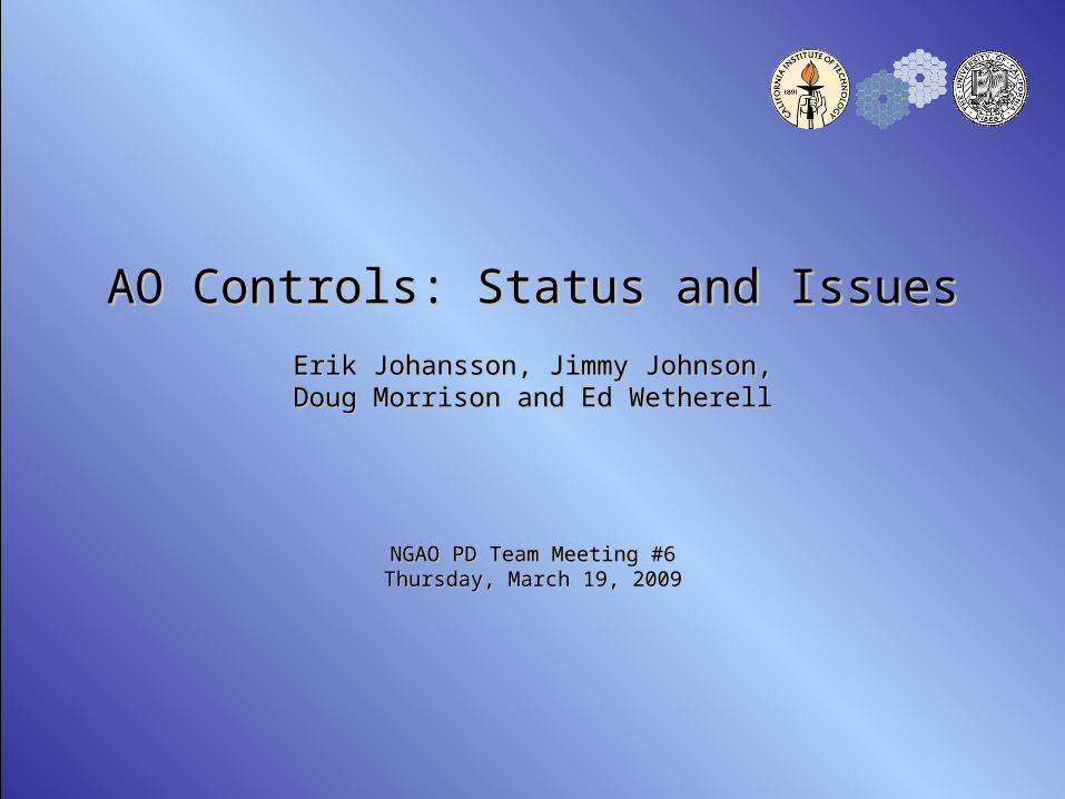
Controls• Originally called non-RTC Controls --> renamed for simplicity• Controls encompasses “everything but the kitchen sink”: control of all
devices in the AO and Laser systems– Motion control: control of all movable devices in the system
• All optical stages, shutters, etc.• Does not include position control of deformable or tip-tilt mirrors
– Device control: control of all non-moving devices in the system requiring computer control
• Environmental control– Temperature, humidity, particulates
• Power control• Camera control (setting parameters, not low-level CCD or focal plane control)• DM and TT control
– Any control required not including mirror positioning commands, e.g., control of drive amplifiers, mirror controllers, etc.
• RTC control: set up and operation of the RTC• Laser system control• Data server
– Acquisition, guiding, offloading and pointing control– Instrument control: all coordination and sequencing required to use instrument
with NGAO system– High level coordination and sequencing control of entire NGAO system

3
Major areas of effort
• Overall control system architecture• Software architecture• Sequencer design: Multi-System Command Sequencer (MCS), AO
Sequencer, Laser Sequencer– Sequencers are main command processors and command sequencers
used to control the system
• AO and Laser system SW design (SW not included in sequencers)• Motion control architecture• Motion control design, both HW and SW• Data server design• User interface design• SW standards document
4
Control system architecture
• Control system architecture and SW architecture are deeply intertwined
• Distributed control system organized hierarchically• Independent subsystems, but MCS is master• Instrument does NOT control AO system and telescope
– Instruments in current AO system do this
– Troubleshooting is problematic
– Instrument should be a subsystem of the overall NGAO system
• Each subsystem has levels of control within it
5
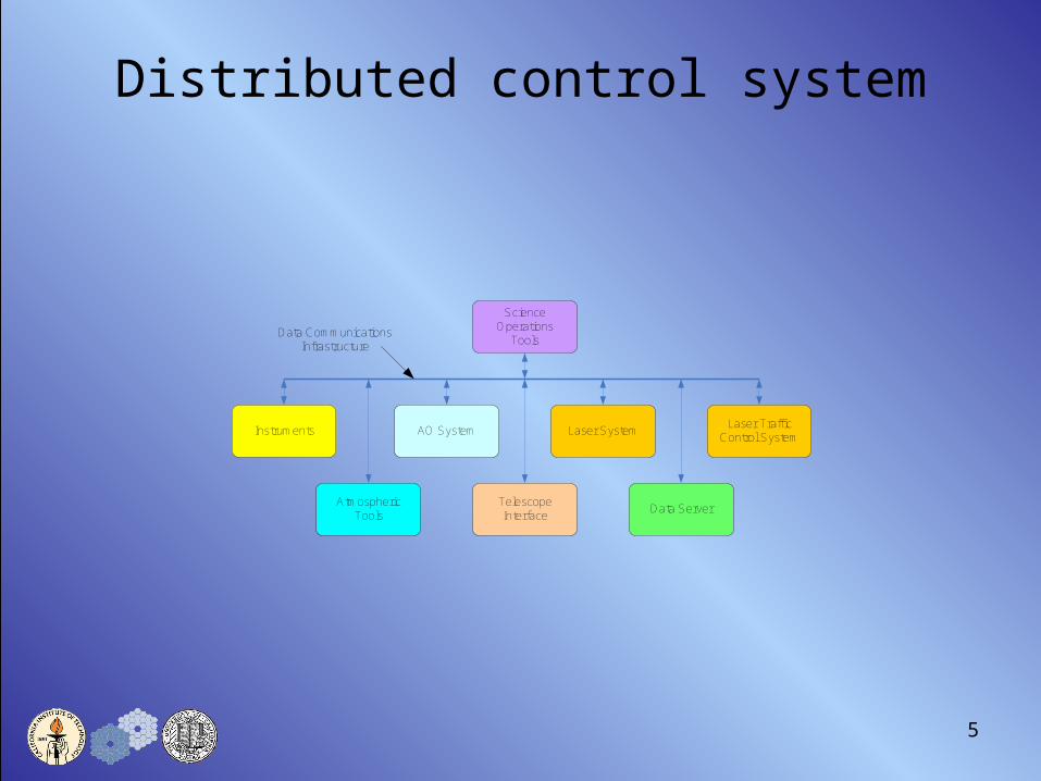
Distributed control system
Data ServerAtmospheric
ToolsTelescope Interface
Instruments Laser SystemAO SystemLaser Traffic
Control System
ScienceOperations
ToolsData Communications
Infrastructure
6
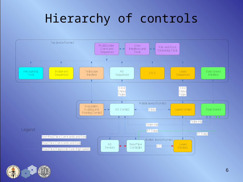
Hierarchy of controls
UserInterfaces and
Tools
Data ServerInterface
Atmospheric Tools
Telescope Interface
Instrument Sequencer
LaserSequencer
LaserDevices
AODevices
AOSequencer
LTCS
AO Control Laser Control
Pre- and Post-Observing Tools
Multi-SystemCommandSequencer
Data ServerAcquisition, Guiding and
Pointing Control
CmdStatusTelem
CmdStatusTelem
Real-Time Controller
RT DiagsRT Diags
TelemetryTelemetry
Legend:
Non-Real-Time Commands and Data
Real-Time Commands and Data
Real-Time Diagnostic Data (high-speed)UTT
Status
Top level of control
Middle level of control
Bottom level of control
7
Software architecture
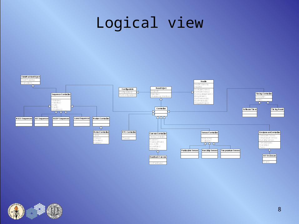
• SW architecture “views”– Logical view
• Shows object decomposition
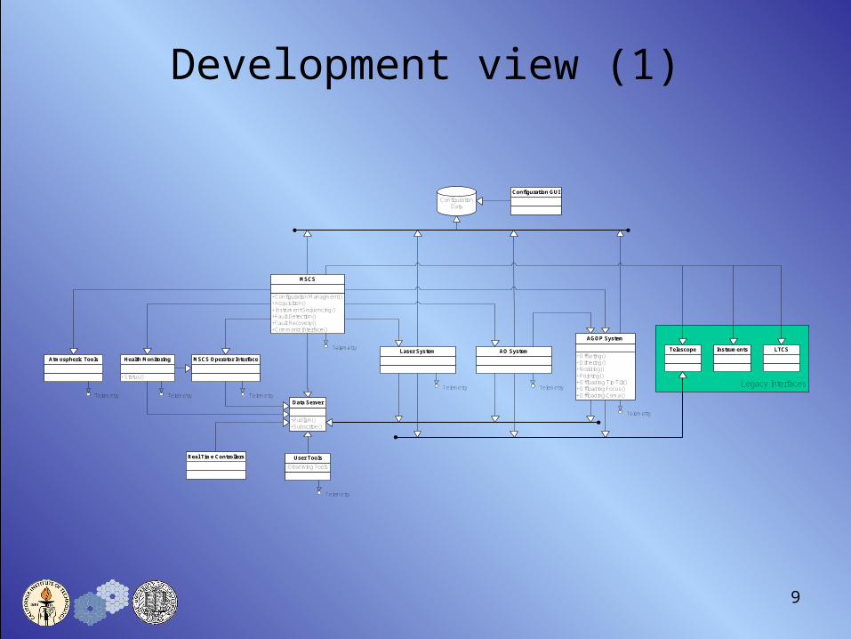
– Development view• SW module organization• Shows interaction of SW components
– Layered view• Shows interaction of SW components in layered hierarchy
– Physical view• Maps SW to HW• Preliminary mapping during PD phase• Full definition during DD phase
– Process view• Shows SW decomposition to tasks, threads, processes• This view will be defined during the DD phase
8
Logical view
+Identity()+Middleware Interface()
-ObjectID
BaseObject
+GetConfiguration()
-ConfigurationID
Configurable +GetAlarmStatus()+SetAlarmStatus()+AcknowledgeAlarm()+ResetAlarm()+SetThreashold()+GetThreshold()+RegisterObject()
-HealthTelemetry-HealthID
Health
Controller
+Initialize()+Standby()+Halt()+Fault()+Shutdown()
Sequence Controller
MSCS Sequencer AO Sequencer AGOP Sequencer Laser Sequencer
+Expose()+ExposureRate()+On / Off()+Waveform()+Binning()
-Timing Controller
Camera Controller
+Rate()
-Resolution
Timing Controller
Software Timer Timing Board
+GetCount()+Calibrate()
Sensor Controller
+Temperature()+Humidity()+Fan()
-Partciulate Sensor-Temperature Sensor-Humidity Sensor
EnvironmentController
Temperature SensorHumidity Sensor
+Cryo()
AO Enclosure
Particulate Sensor
+Transition()
-State Mappings
StateMachineObject
Motion Controller
+Home()+Position()+Status()
-Limits
Motor Controller
+GetPixelData()
Readback Camera
+Power()
RTC Controller
9
Development view (1)
+Configuration Managment()+Acquisition()+Instrument Sequencing()+Fault Detection()+Fault Recovery()+Command Interface()
MSCS
Atmospheric Tools+Offseting()+Dithering()+Nodding()+Pointing()+Offloading Tip-Tilt()+Offloading Focus()+Offloading Coma()
AGOP System
Laser System AO System
+Publish()+Subscribe()
Data Server
MSCS Operator Interface
-Observing Tools
User Tools
+Status()
Health Monitoring
Legacy Interfaces
Instruments LTCSTelescope
Configuration Data
Configuration GUI
Telemetry Telemetry Telemetry
Telemetry
Telemetry
Telemetry Telemetry
Telemetry
Real Time Controllers

10
Development view (2)
AO System Telemetry
Configuration
MSCS
Data Server
AO Environment Control
DM Power Controller
Particular Sensor Temperature SensorHumidity Sensor AO Cooling
Vibration Sensor LSG WFS Camera
NGS Acq. Camera Tip-Tilt Sensor
LOWFS TWFS CameraTTFA Camera
NGS WFS Camera
LGS WFS Controller ADC Controller NGS FSM ControllerLOWFS Controller IF FSM Controller Focus Manager Controller
Driver Driver DriverDriver Driver Driver Driver
Driver Driver Driver Driver
RTC ? Driver
Pickoff Controller (x3)
Pickoff Controller (x3)
ADC Controller (xN)
FSM Controller (x2)
FSM Controller (x2) ?????
Driver Driver Driver Driver Driver
AO Sequencer
11
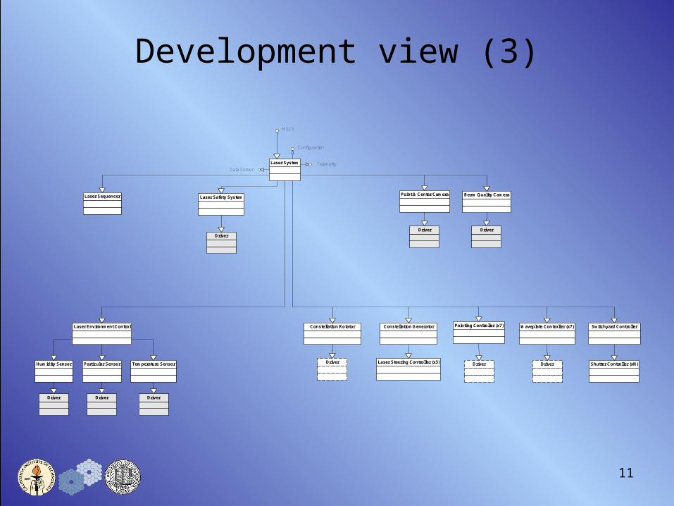
Development view (3)
Laser System Telemetry
Configuration
MSCS
Data Server
Laser Environment Control
Laser Safety System
Particular Sensor Temperature SensorHumidity Sensor
Point & Center Camera Beam Quality Camera
Constellation Generator
Driver Driver
Driver Driver Driver
Driver
Laser Steering Controller (x3)
Pointing Controller (x7)
Driver
Switchyard ControllerWaveplate Controller (x7)
Shutter Controller (xN)Driver
Constellation Rotator
Driver
Laser Sequencer

12
Development view (4)
AGOP System
Telemetry
Configuration
MSCS
Data Server
Guiding CameraComa Offload ControllerTip-Tilt Offload Controller
13
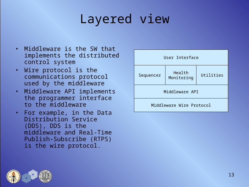
Layered view
• Middleware is the SW that implements the distributed control system
• Wire protocol is the communications protocol used by the middleware
• Middleware API implements the programmer interface to the middleware
• For example, in the Data Distribution Service (DDS), DDS is the middleware and Real-Time Publish-Subscribe (RTPS) is the wire protocol.
Middleware Wire Protocol
Middleware API
Sequencer
User Interface
HealthMonitoring
Utilities

14
Middleware evaluation• We are evaluating several
different middleware technologies for use in NGAO
• Evaluation topics:– Services:
• Logging• Data archiving• Alarming• Health monitoring• Configuration• Telemetry• Administration• Event support• User interfaces
– Language support• Python• Java• C/C++
– Communication• Point to point• Multicast• Data support• Synchronous• Asynchronous• Publish-subscribe
– Application development• Inheritance• Loosely coupled• Location transparency• Type mapping
– Performance• Evaluations on 3 PCs• VMWare to easily switch between
environments
15
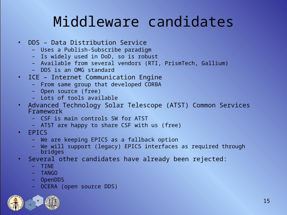
Middleware candidates• DDS – Data Distribution Service
– Uses a Publish-Subscribe paradigm– Is widely used in DoD, so is robust– Available from several vendors (RTI, PrismTech, Gallium)– DDS is an OMG standard
• ICE – Internet Communication Engine– From same group that developed CORBA– Open source (free)– Lots of tools available
• Advanced Technology Solar Telescope (ATST) Common Services Framework– CSF is main controls SW for ATST– ATST are happy to share CSF with us (free)
• EPICS– We are keeping EPICS as a fallback option– We will support (legacy) EPICS interfaces as required through bridges
• Several other candidates have already been rejected:– TINE– TANGO– OpenDDS– OCERA (open source DDS)

16
Sequencer concept
• Command – response design pattern– Encapsulates action, parameters, response
• Compound tasks (workflows) are straightforward to build– Simple syntax will allow SAs to write scripts
• Thread pool to handle multiple asynchronous tasks• Easy to build UI around
17
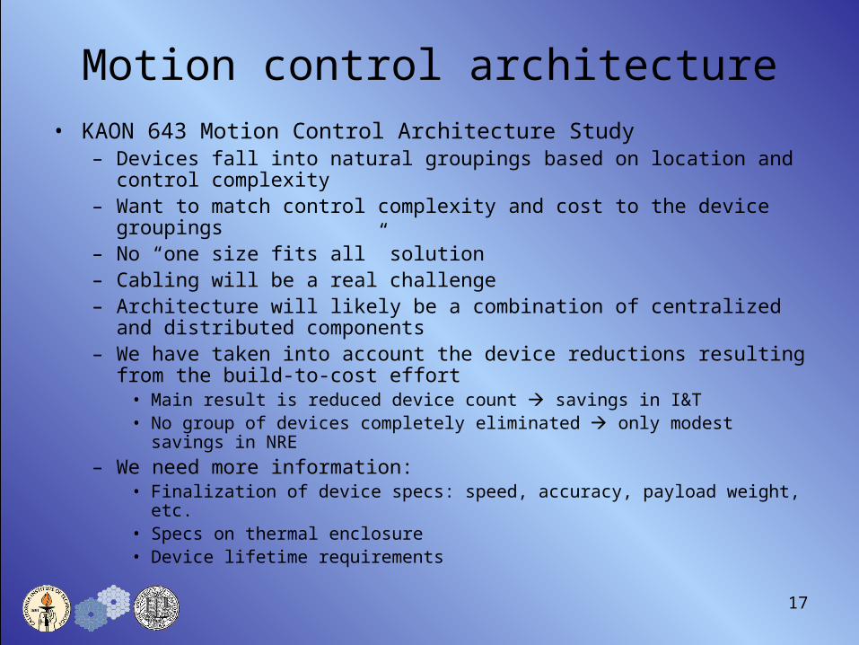
Motion control architecture• KAON 643 Motion Control Architecture Study
– Devices fall into natural groupings based on location and control complexity
– Want to match control complexity and cost to the device groupings– No “one size fits all” solution– Cabling will be a real challenge– Architecture will likely be a combination of centralized and distributed
components– We have taken into account the device reductions resulting from the
build-to-cost effort• Main result is reduced device count savings in I&T• No group of devices completely eliminated only modest savings in NRE
– We need more information:• Finalization of device specs: speed, accuracy, payload weight, etc.• Specs on thermal enclosure• Device lifetime requirements

18
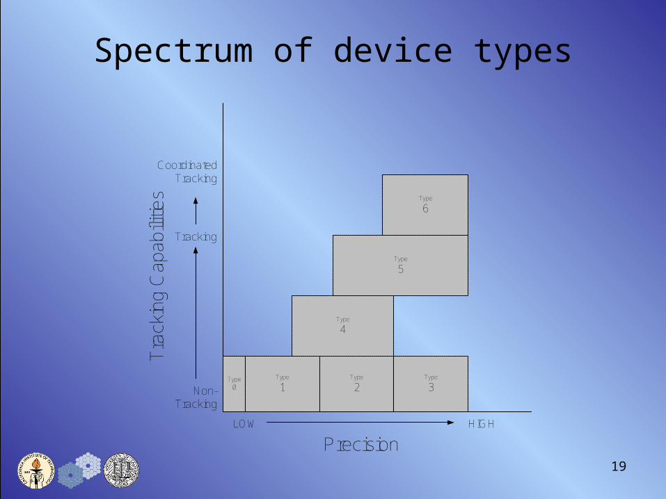
Device groupings(0) Shutters
– simple in/out devices with very loose positional requirements– actual position when moving is not required
(1) Low precision, non-tracking– moved during configuration, not during an observation– a dichroic or fold, for example
(2) Medium precision, non tracking– moved during configuration, not during an observation– aligning a fold (tip/tilt) or other component
(3) High precision, non-tracking– moved during configuration or acquisition, not during an observation– aligning a lenslet or focusing a unit
(4) Tracking– synchronized to external inputs, constantly moving– ADCs, rotators
(5) Extremely high precision (non)tracking– coordinated motion with other DOF(s), possibly tracking– Field steering mirrors, focus adjustment
(6) Pickoff arms - coordinated high precision (non)tracking– most demanding DOF, coordinated motion with other DOF(s), synched to external inputs– spatial position constraints, based on static and dynamic obstacles, to avoid collision
19
Precision
Tra
ckin
g C
apab
ilitie
s
LOW HIGH
Non-Tracking
Tracking
Coordinated Tracking
Type0
Type
1Type
2Type
3
Type
4
Type
5
Type
6
Spectrum of device types
20
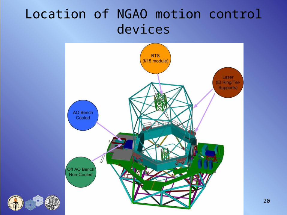
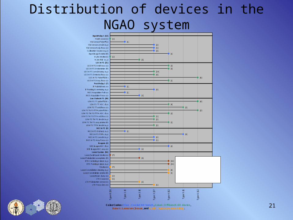
Location of NGAO motion control devices
21
[1]
[1]
[1]
[1]
[6]
[7]
[14]
[14]
[3]
[7]
[1]
[2]
[1]
[2]
[4]
[1]
[2]
[1]
[2]
[1]
[2]
[2]
[2]
[4]
[4]
[1]
[1]
[4]
[1]
[6]
[3]
[2]
[1]
[1]
[1]
[2]
[1]
[1]
[1]
[4]
[14]
[3]
[3]
[1]
Typ
e 6
[12]
Typ
e 5
[6]
Typ
e 4
[52]
Typ
e 3
[37]
Typ
e 2
[8]
Typ
e 1
[4]
Typ
e 0
[18]
LTO Focus lens (x)
LTO Polarization sensor (x)
LTO Cover (x)
Laser Beam dump (x)
Laser Constellation rotator (θ)
Laser Constellation steering (x,y)
Shutter (x)
BTO Pointing mirrors (x,y)
BTO Centering mirrors (x,y)
Laser Polarization waveplates (θ)
Laser Switchyard shutter (x)
Laser System [56]
NIR Imager ADC assy (x)
NIR Imager ADC (θ,x)
Imagers [3]
NGS WFS Assy Focus (z)
NGS WFS Lenslet (x,y)
NGS WFS FSMs (x,y)
NGS WFS Dichroic (x,z)
NGS WFS [8]
LOWFS TTFA lenslet (x,y)
LOWFS TWFS assy rotator (θ)
LOWFS TWFS lenslet (x,y)
LOWFS TWFS/TTFA unit focus (z)
LOWFS TWFS/TTFA ADC (θ,x)
LOWFS TWFS/TTFA pickoff (θ,Φ)
LOWFS TT unit focus (z)
LOWFS TT ADC (θ,x)
LOWFS TT pickoff (θ,Φ)
Low Order WFS [20]
NGS Acquisition Focus (z)
NGS Acquisition Fold (x)
IF Pointing & centering (x,y)
IF Fold/dichroic (x)
Post Relay 1 [7]
LGS WFS Assy focus (z)
LGS WFS Pickoff (θ,Φ)
LGS WFS Detector focus (z)
LGS WFS Lenslet array (x,y)
LGS WFS Unit rotation (θ)
LGS WFS Unit Focus (z)
LGS WFS [31]
Wyko fold (x, y)
Wyko shutter (x)
Input Image Rotator (θ)
Calibration Source (x,y,z)
Vib Sensor Assly focus (z)
Vib Sensor Lenslet (x,y)
Vib Sensor Pickoff (x)
Hatch cover (x)
Input/Relay 1 [12]
Color Codes: Blue - Cooled AO bench, Green: Off-bench AO device, Brown: Laser enclosure, and Gold: Telescope secondary.
Type 0 - ShutterType 1 - Low precision, non-trackingType 2 - Med precision non-trackingType 3 - High precision non-trackingType 4 - TrackingType 5 - Coordinated trackingType 6 - Pickoff arms
Distribution of devices in the NGAO system
22
Motion control recommendations• Architecture:
– Centralized control for high-precision tracking devices– Distributed control for other devices
• Consider device multiplexing for type 0 devices to reduce control infrastructure
• Use smart motors for distributed control where possible. More analysis of the thermal constraints is required.
• Control components should be specified based on device requirements. “One size fits all” will be too costly and may not be feasible.
• HW selection should be done in collaboration with SW designers• HW should support maintenance and troubleshooting. Devices in cooled AO
bench should require minimum support.• Careful considerations must be taken to minimize EMI.• Use COTS controllers and packaging to reduce overall system cost.• Need better device specifications to proceed: Device Description Sheets.• Now is the time to begin collaborations with the design teams.
23
Issues
• Lack of information has been the biggest obstacle to date.• Now that B2C effort is drawing to a close, it is time to begin closer
collaborations with the other design teams.• We need as much information as possible on all the devices to be
used throughout the system.• We will be calling to set up meetings/teleconferences to kick off the
process and envision many “working” conferences and calls in the future.