Embed Size (px)
Citation preview
A Short Introduction A Short Introduction to Adaptive Opticsto Adaptive Optics
Presentation for NGAO Controls TeamPresentation for NGAO Controls Team
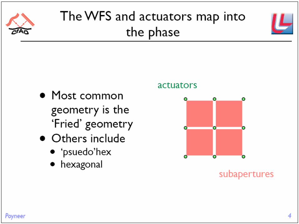
Erik JohanssonErik JohanssonAugust 28, 2008August 28, 2008
2
OverviewOverview
• Why we need AO• The basics of AO• Intro to wavefront sensing• Intro to tip-tilt correction• Intro to higher-order wavefront correction• LGS vs NGS AO• Limitations of AO• How NGAO will differ form our current AO
system• Q&A
3
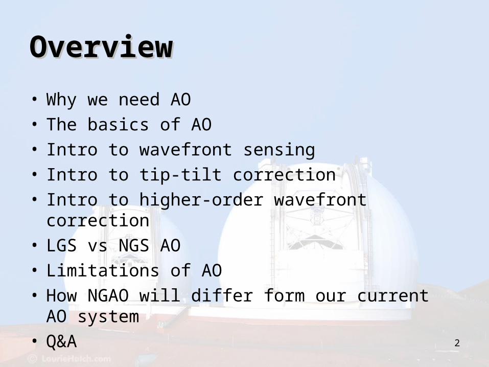
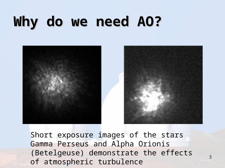
Why do we need AO?Why do we need AO?
Short exposure images of the stars Gamma Perseus and Alpha Orionis (Betelgeuse) demonstrate the effects of atmospheric turbulence

4
Light from distant star
Telescope aperture
Focal Plane
Image
Spot size = 2.44 /D
Without atmosphere, the telescope Without atmosphere, the telescope forms a perfect “diffraction-limited” forms a perfect “diffraction-limited” spot in the focal planespot in the focal plane

5
Light from distant star
Telescope aperture
Focal Plane
Image
Atmosphere (lens size = r0)
Spot size = 2.44 /r0
Freeze the speckles by using short exposures < ~0.1 sec
r0 is characteristic size of the atmosphere
Number of speckles ~ (D/r0)2
First characterized by Fried in 1966
What is D/r0 for Keck?
The atmosphere acts like many lenses The atmosphere acts like many lenses of size r0 to create moving “speckles” of size r0 to create moving “speckles” in the imagein the image
6
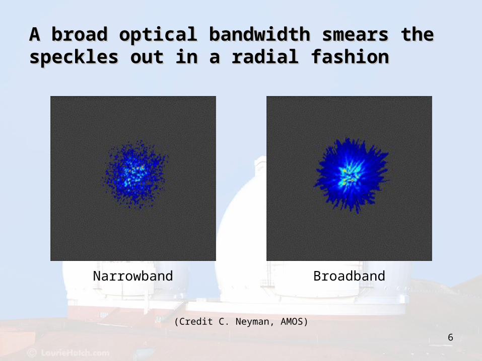
Narrowband Broadband
(Credit C. Neyman, AMOS)
A broad optical bandwidth smears theA broad optical bandwidth smears thespeckles out in a radial fashionspeckles out in a radial fashion

7
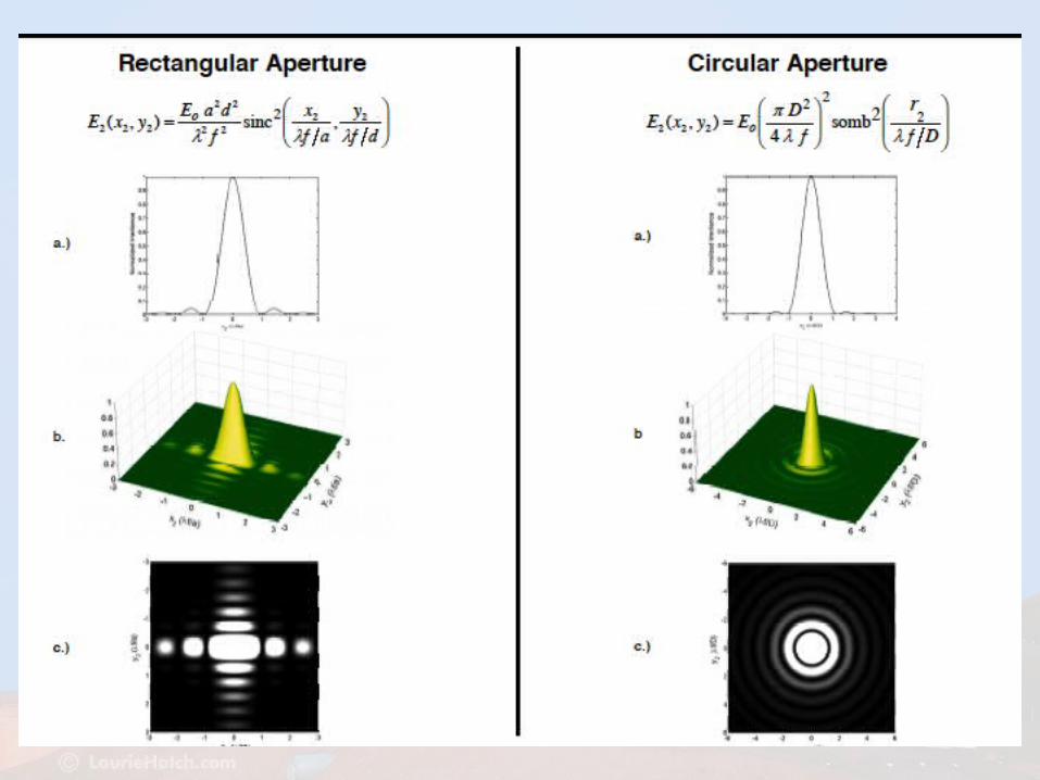
Details of diffraction Details of diffraction from circular aperturefrom circular aperture
1) Amplitude
2) Intensity
First zero at r = 1.22 / D
FWHM / D
8

9
Diffraction pattern from Diffraction pattern from hexagonal Keck hexagonal Keck telescopetelescope
Ghez: Keck laser guide star AO
Stars at Galactic Center

10
A sheet with a sinusoidal “wave” which can vary in frequency (wavelength) and orientation (direction)
A spatial frequency also has phase: its peaks and valleys have some kind of reference to a known point in the image
What is a spatial frequency?What is a spatial frequency?

11
Telescope OTF
Seeing Limited TF
Tip-Tilt Compensated TF
For D/r0 = 15
How does the atmosphere affect How does the atmosphere affect system performance? system performance?
Normalized Spatial Frequency

The Basics of AOThe Basics of AO
13
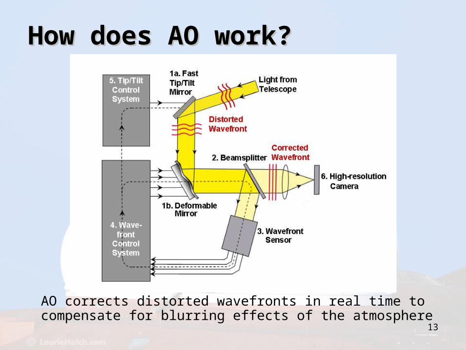
How does AO work?How does AO work?
AO corrects distorted wavefronts in real time to compensate for blurring effects of the atmosphere

14
What do AO and flying What do AO and flying potato chips have in potato chips have in common?common?
Intro to Wavefront Intro to Wavefront SensingSensing
16
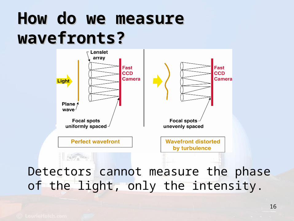
How do we measure How do we measure wavefronts?wavefronts?
Detectors cannot measure the phase of the light, only the intensity.

17
Intro to Tip-Tilt Intro to Tip-Tilt CorrectionCorrection
19
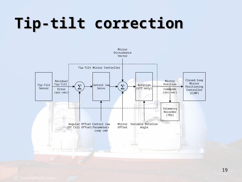
TelemetryRecorder
(TRS)
Tip-Tilt Mirror Controller
Tip-TiltSensor
Closed-loopMirror
PositioningController(CLMP)
ResidualTip-Tilt
Error(arc-sec)
MirrorPosition
Commands(arc-sec)
Rotation(UTT only)
Variable RotationAngle
Angular Offset(DT Ctrl Offset)
Control lawParametersLoop cmd
Control lawServo
MirrorDisturbance
Vector
MirrorOffset
Tip-tilt correctionTip-tilt correction

20
Closed-Loop Mirror Positioning Controller
AtmosphericTip-Tilt
Controller
PIDServo
High voltageAmplifier
Digital toAnalog
Converter
MirrorActuators
MirrorPosition
Commands
(arc-sec)
High voltageActuator
Signals
BridgeSensors
StrainGauge
Outputs
CurrentMirror
Position
Arc-sec toactuator space
conversion
ConversionMatrix
ServoParameters
Closed Loop Mirror Closed Loop Mirror PositioningPositioning
Intro to Wavefront Intro to Wavefront Reconstruction and Reconstruction and CorrectionCorrection
22
23
24
Wave FrontSensor(WFS)
Camera
BackgroundCompensation
Flat FieldCompensation
Pixel threshold
CentroidComputation
Control lawServo
Matrix-VectorMultiply
DeformableMirror(DM)
Tip-tiltControllers(DTT/UTT)
Background imageFlat field
Intensity thresholdCentroid gainCentroid origin
ReconstructionMatrix
Control lawParameters
Loop commandActuator map
DM origin
WFSparameters
TelemetryRecorder
(TRS)
Raw framesCentroids
Subap intensity
Residual WF errorRSS Residual WF Error
Tip-tilt errorWFS focus error
Actuator vectorDM focus
DMHWIF
WFSHWIF
Tip-tilt
error
Wave Front Processor (WFP)
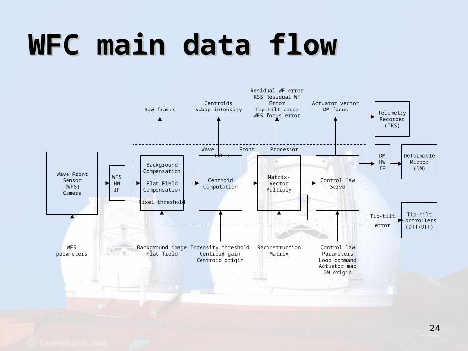
WFC main data flowWFC main data flow
25
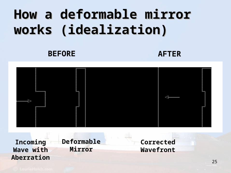
BEFORE AFTER
Incoming Wave with Aberration
Deformable Mirror
Corrected Wavefront
How a deformable mirror How a deformable mirror works (idealization)works (idealization)

26
Deformable Mirror for real wavefronts
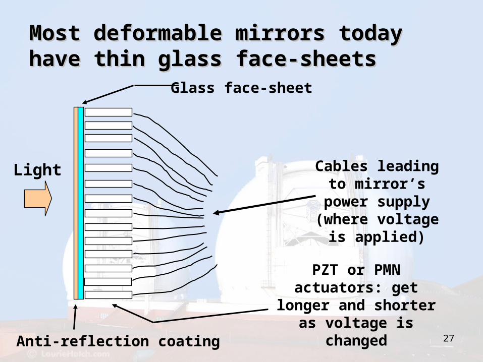
27Anti-reflection coating
Glass face-sheet
PZT or PMN actuators: get longer and shorter as voltage is changed
Cables leading to mirror’s power supply (where
voltage is applied)
Light
Most deformable mirrors today Most deformable mirrors today have thin glass face-sheetshave thin glass face-sheets

28
(paper coasters)
349 degrees of freedom; ~250 in use at any one time
Front view of Xinetics DM Front view of Xinetics DM (Keck)(Keck)
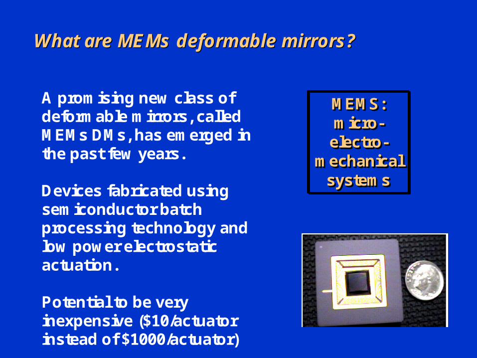
What are What are MEMs MEMs deformable mirrors?deformable mirrors?
A prom ising new class of deform able m irrors, called M EM s DM s, has em erged in the past few years.
Devices fabricated using sem iconductor batch processing technology and low pow er electrostatic actuation.
Potential to be very inexpensive ($10/actuator instead of $1000/actuator)
MEMS: micro-
electro-mechanical
systems
MEMS: MEMS: micromicro--
electroelectro--mechanical mechanical
systemssystems
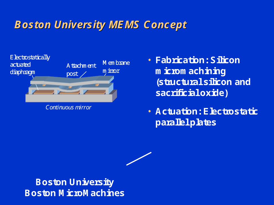
Boston University MEMS ConceptBoston University MEMS Concept
Electrostatically actuated diaphragm
Attachment post
M embrane mirror
Electrostatically actuated diaphragm
Attachment post
M embrane mirror
Continuous mirror
• Fabrication: Silicon micromachining (structural silicon and sacrificial oxide)
• Actuation: Electrostatic parallel plates
Boston University Boston MicroMachines

NGS vs LGS AONGS vs LGS AO
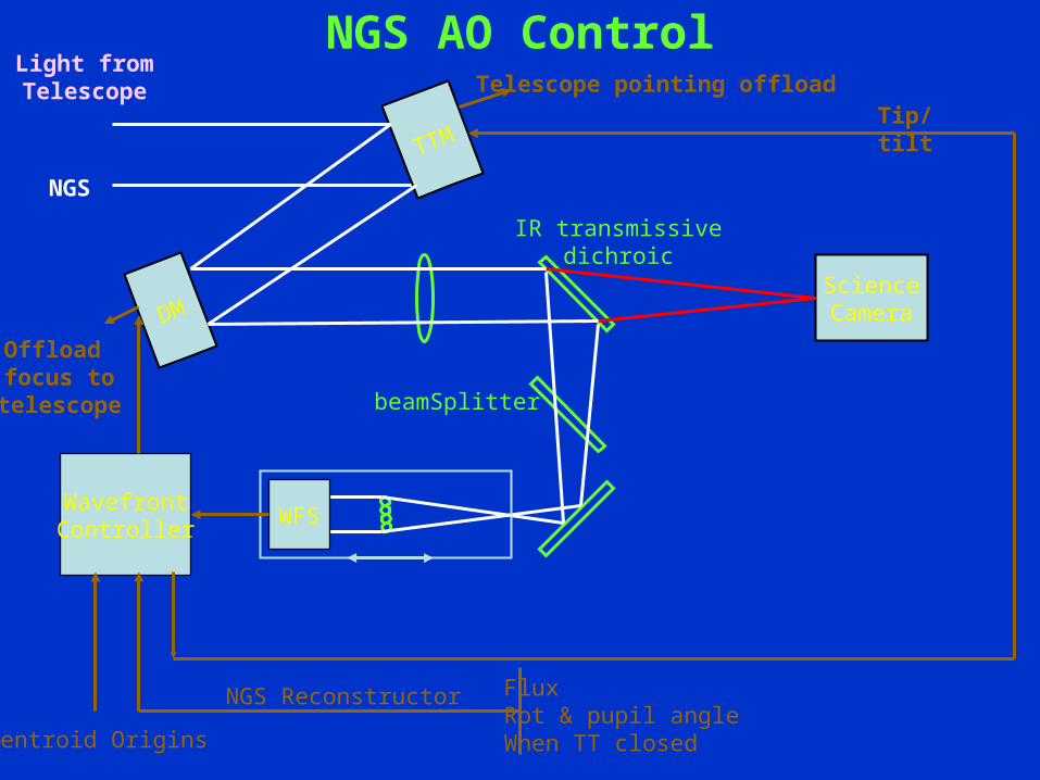
DMScienceCamera
TTM
WFS
NGS
WavefrontController
Tip/tilt
IR transmissivedichroic
beamSplitter
Telescope pointing offload
Offload focus to
telescope
Light fromTelescope
NGS AO Control
NGS Reconstructor FluxRot & pupil angleWhen TT closedCentroid Origins
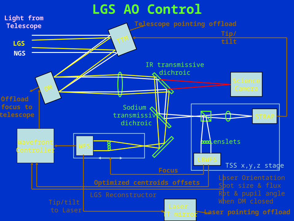
DMScienceCamera
STRAP
LBWFS
TTM
WFS
NGS
WavefrontController
Focus
Optimized centroids offsets
Tip/tilt
IR transmissivedichroic
LGS
Sodium transmissive
dichroic
Lenslets
Telescope pointing offload
Offload focus to
telescope
Tip/tilt to Laser
Light fromTelescope
LGS AO Control
LGS Reconstructor
TSS x,y,z stage
Laser TT mirror Laser pointing offload
Laser OrientationSpot size & fluxRot & pupil angleWhen DM closed
34
Limitations of AOLimitations of AO
• Isoplanatism– Tip-Tilt Isoplanatism– Focus isoplanatism
• Sky coverage– WFS sensitivity– TT sensor sensitivity
• Imaging wavelength• Controller bandwidth• Error budgets, and more…
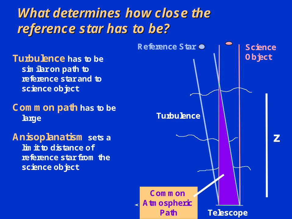
What determines how close the What determines how close the reference star has to be?reference star has to be?
Turbulence has to be similar on path to reference star and to science object
Common path has to be large
Anisoplanatism sets a limit to distance of reference star from the science object
Reference StarReference Star ScienceObjectScienceObject
Telescope
Turbulence
Telescope
Turbulence
zz
Common Atmospheric
Path
Common Atmospheric
Path
Common Atmospheric
Path
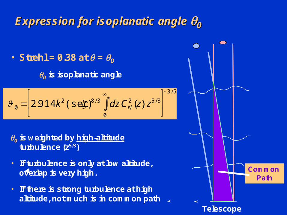
Expression for Expression for isoplanatic isoplanatic angle angle 00
• Strehl = 0.38 at = 0
0 is isoplanatic angle
0 is weighted by high-altitudeturbulence (z5/3)
• If turbulence is only at low altitude, overlap is very high.
• If there is strong turbulence at high altitude, not much is in common path
0 2.914 k 2(sec )8 / 3 dz CN2 (z) z5 / 3
0
3 / 5
Telescope
Common Path
37
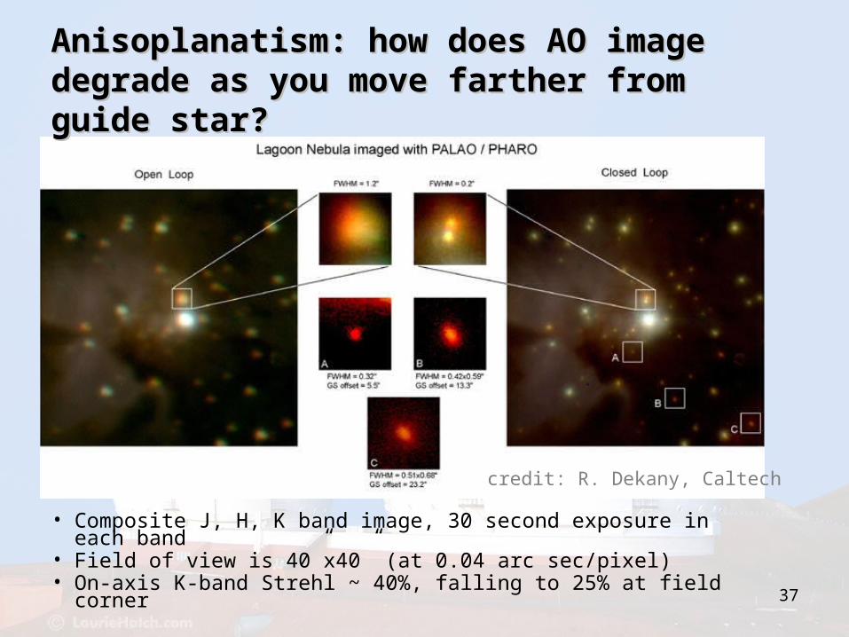
• Composite J, H, K band image, 30 second exposure in each band
• Field of view is 40”x40” (at 0.04 arc sec/pixel)• On-axis K-band Strehl ~ 40%, falling to 25% at field corner
credit: R. Dekany, Caltech
Anisoplanatism: how does AO image Anisoplanatism: how does AO image degrade as you move farther from degrade as you move farther from guide star?guide star?
38
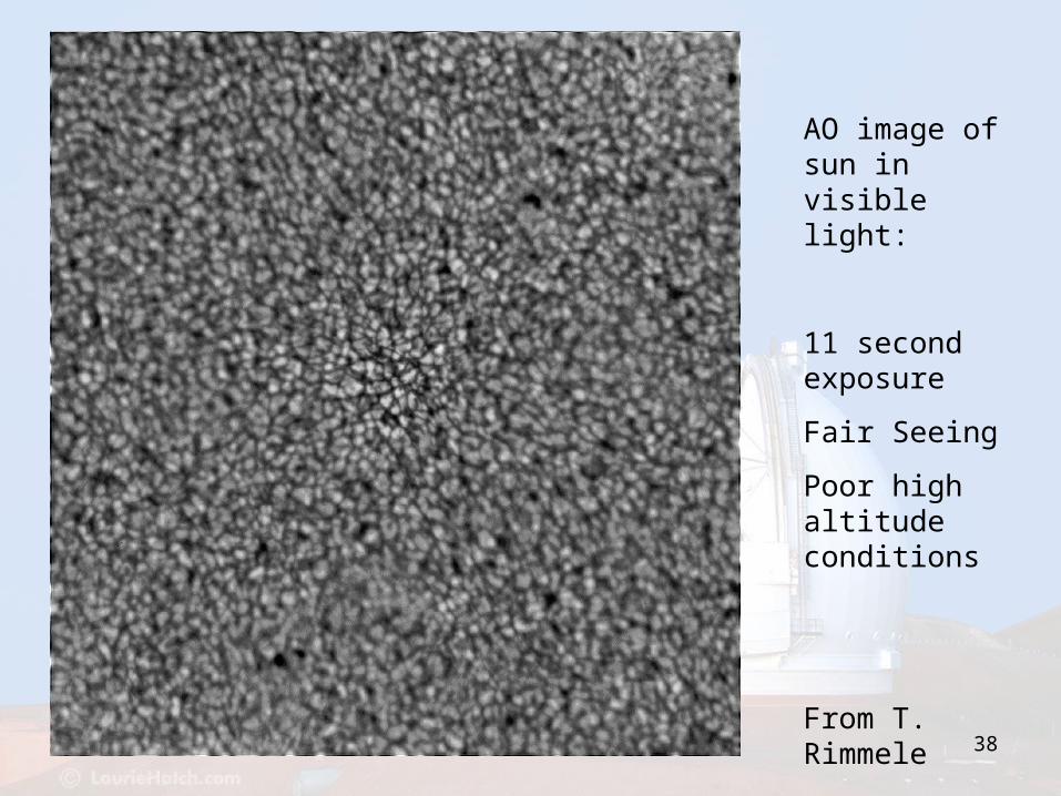
AO image of sun in visible light:
11 second exposure
Fair Seeing
Poor high altitude conditions
From T. Rimmele
39
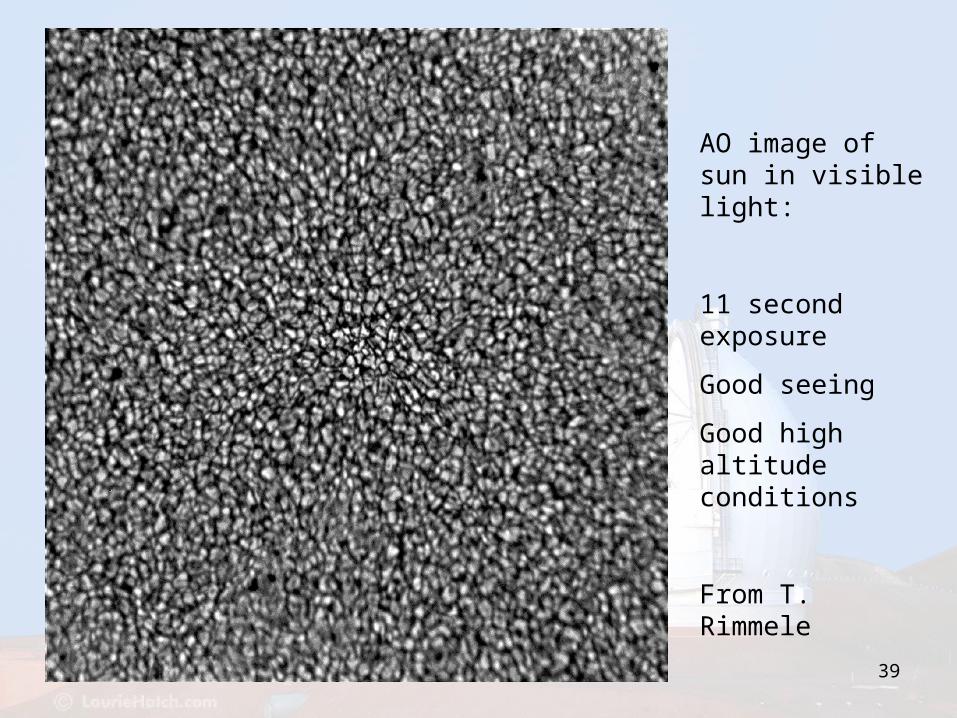
AO image of sun in visible light:
11 second exposure
Good seeing
Good high altitude conditions
From T. Rimmele
40
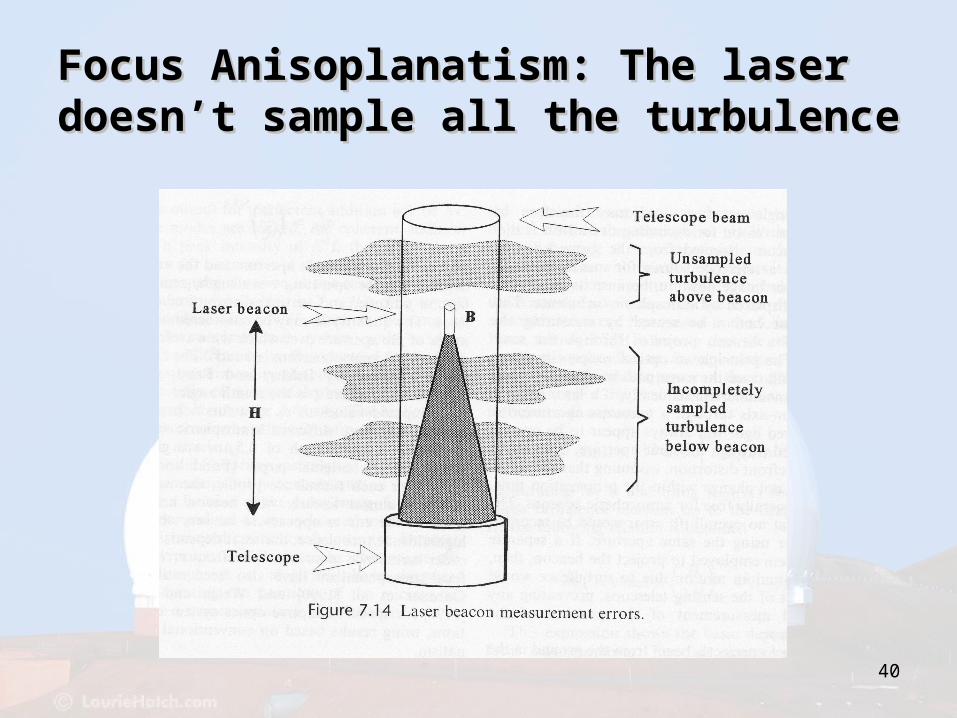
Focus Anisoplanatism: The laser Focus Anisoplanatism: The laser doesn’t sample all the turbulencedoesn’t sample all the turbulence
Additional slides from Additional slides from Claire Max’s UCSC ClassClaire Max’s UCSC Class
NGWFC ResultsNGWFC Results
43
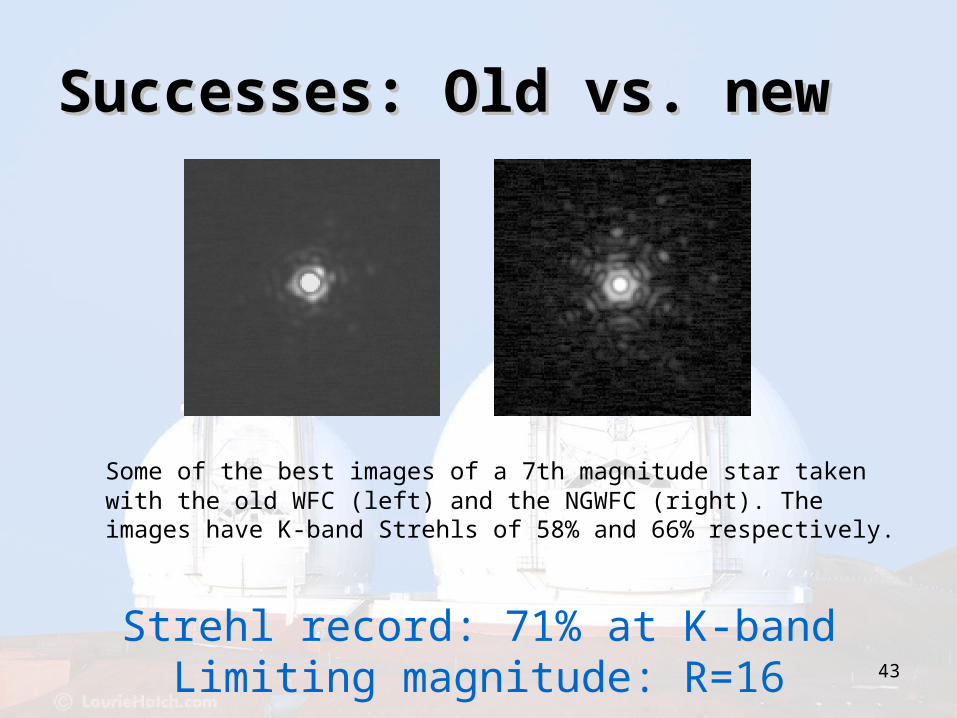
Successes: Old vs. newSuccesses: Old vs. new
Some of the best images of a 7th magnitude star taken with the old WFC (left) and the NGWFC (right). The images have K-band Strehls of 58% and 66% respectively.
Strehl record: 71% at K-bandLimiting magnitude: R=16
44
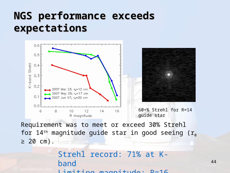
NGS performance exceeds NGS performance exceeds expectationsexpectations
Requirement was to meet or exceed 30% Strehl for 14th magnitude guide star in good seeing (r0 ≥ 20 cm).
60+% Strehl for R=14 guide star
Strehl record: 71% at K-bandLimiting magnitude: R=16
45
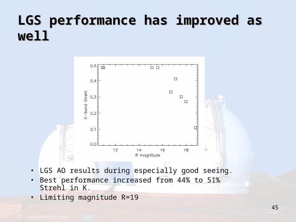
LGS performance has improved as LGS performance has improved as wellwell
• LGS AO results during especially good seeing.• Best performance increased from 44% to 51% Strehl in
K.• Limiting magnitude R=19
46
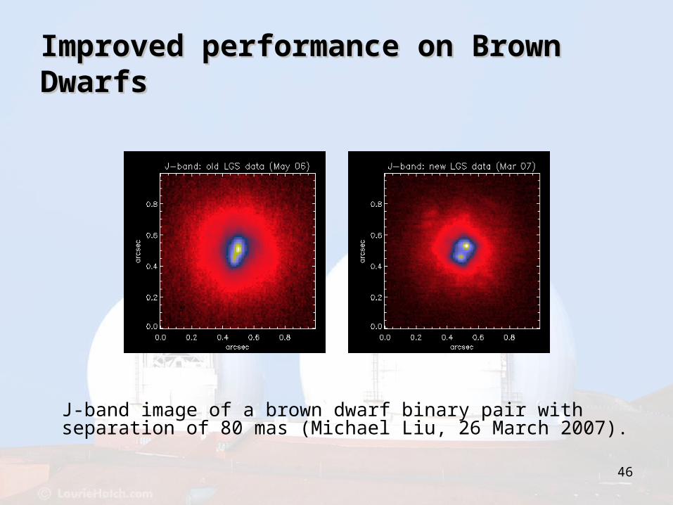
Improved performance on Brown Improved performance on Brown DwarfsDwarfs
J-band image of a brown dwarf binary pair with separation of 80 mas (Michael Liu, 26 March 2007).

47
Best LGS AO images of the Best LGS AO images of the galactic centergalactic center
K-band image of the Galactic Center in LGS AO (left) and NGS AO (right). Credit: Andrea Ghez, Jessica Lu.
48
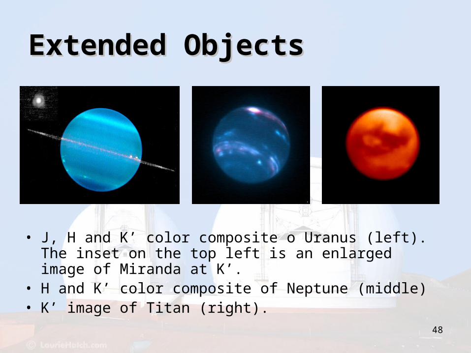
Extended ObjectsExtended Objects
• J, H and K’ color composite o Uranus (left). The inset on the top left is an enlarged image of Miranda at K’.
• H and K’ color composite of Neptune (middle) • K’ image of Titan (right).
49
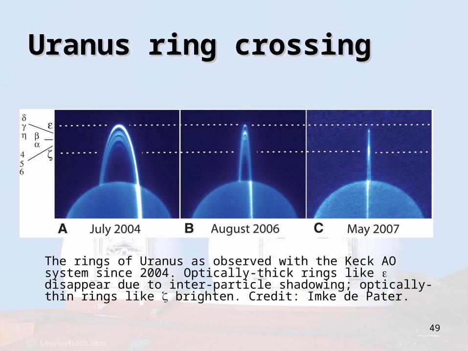
Uranus ring crossingUranus ring crossing
The rings of Uranus as observed with the Keck AO system since 2004. Optically-thick rings like disappear due to inter-particle shadowing; optically-thin rings like brighten. Credit: Imke de Pater.
50
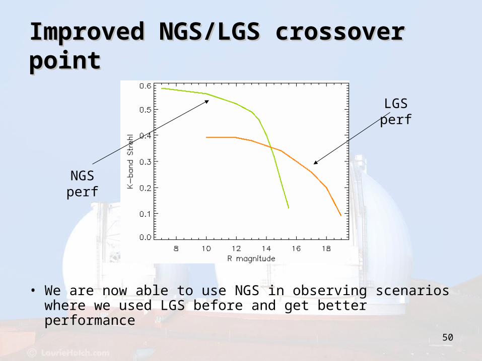
Improved NGS/LGS crossover Improved NGS/LGS crossover pointpoint
• We are now able to use NGS in observing scenarios where we used LGS before and get better performance
NGS perf
LGS perf