Embed Size (px)
Citation preview
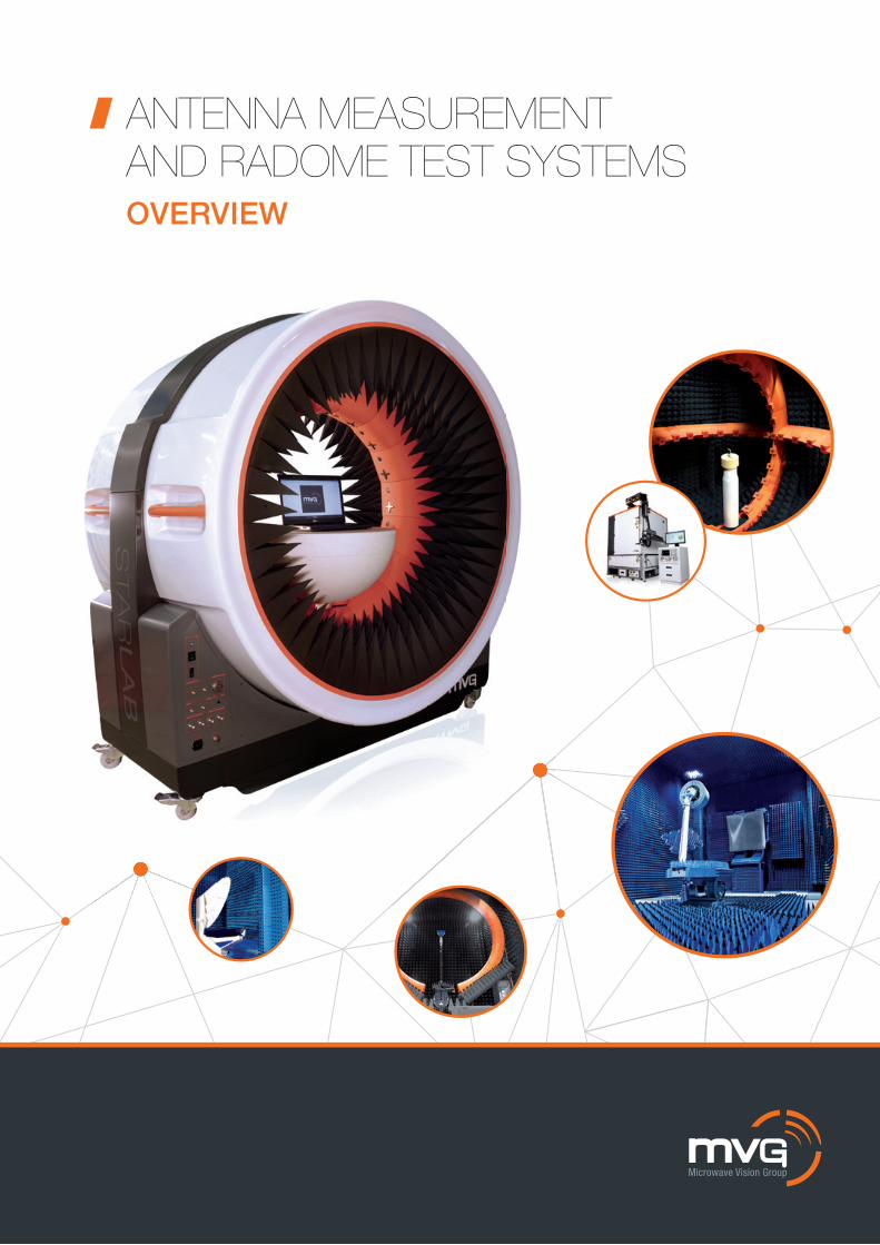
ANTENNA MEASUREMENT AND RADOME TEST SYSTEMSOVERVIEW
2
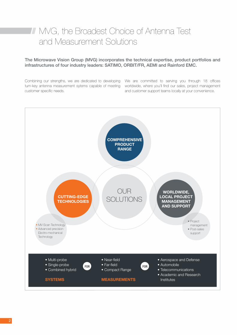
MVG, the Broadest Choice of Antenna Test and Measurement Solutions
The Microwave Vision Group (MVG) incorporates the technical expertise, product portfolios and infrastructures of four industry leaders: SATIMO, ORBIT/FR, AEMI and Rainford EMC.
Combining our strengths, we are dedicated to developing turn-key antenna measurement sytems capable of meeting customer specifi c needs.
We are committed to serving you through 18 offi ces worldwide, where you’ll fi nd our sales, project management and customer support teams locally at your convenience.
• Multi-probe • Single-probe • Combined hybrid
SYSTEMS
• Near-fi eld • Far-fi eld • Compact Range
MEASUREMENTS
• Aerospace and Defense • Automobile• Telecommunications • Academic and Research
Institutes
OUR SOLUTIONS
FOR FOR
COMPREHENSIVEPRODUCT
RANGE
WORLDWIDE, LOCAL PROJECT MANAGEMENT AND SUPPORT
CUTTING-EDGE TECHNOLOGIES
• Project management
• Post-sales support
• MV-Scan Technology• Advanced precision
Electro-mechanical Technology
3
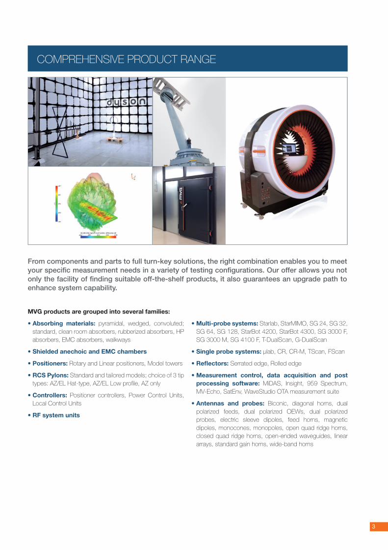
From components and parts to full turn-key solutions, the right combination enables you to meet your specific measurement needs in a variety of testing configurations. Our offer allows you not only the facility of finding suitable off-the-shelf products, it also guarantees an upgrade path to enhance system capability.
MVG products are grouped into several families:
• Absorbing materials: pyramidal, wedged, convoluted; standard, clean room absorbers, rubberized absorbers, HP absorbers, EMC absorbers, walkways
• Shielded anechoic and EMC chambers
• Positioners: Rotary and Linear positioners, Model towers
• RCS Pylons: Standard and tailored models; choice of 3 tip types: AZ/EL Hat-type, AZ/EL Low profile, AZ only
• Controllers: Positioner controllers, Power Control Units, Local Control Units
• RF system units
• Multi-probe systems: Starlab, StarMIMO, SG 24, SG 32, SG 64, SG 128, StarBot 4200, StarBot 4300, SG 3000 F, SG 3000 M, SG 4100 F, T-DualScan, G-DualScan
• Single probe systems: µlab, CR, CR-M, TScan, FScan
• Reflectors: Serrated edge, Rolled edge
• Measurement control, data acquisition and post processing software: MiDAS, Insight, 959 Spectrum, MV-Echo, SatEnv, WaveStudio OTA measurement suite
• Antennas and probes: Biconic, diagonal horns, dual polarized feeds, dual polarized OEWs, dual polarized probes, electric sleeve dipoles, feed horns, magnetic dipoles, monocones, monopoles, open quad ridge horns, closed quad ridge horns, open-ended waveguides, linear arrays, standard gain horns, wide-band horns
COMPREHENSIVE PRODUCT RANGE
4
1/ MV-SCANTM TECHNOLOGY: FAST - ACCURATE - SMART
MV-ScanTM Technology is integrated into all our multi-probe systems. With MV-ScanTM, an array of probes is electronically scanned, increasing measurement speed while also gaining in measurement accuracy. It’s also smart technology that allows for choices in confi gurations in order to limit mechanical movements.
Fast
The need for faster measurement of antennas and radomes is a growing concern in the industry. Not only do our customers want to test signifi cant numbers of beams at once, they want to test more frequently and in a short amount of time. Optimi-zing ROI is essential.
The electronic scanning of an array of ten to hundreds of probes using MV-ScanTM allows the measurement of a full cut in quasi-real time.
Faster measurement time quickens the overall antenna development process
As you gain time in antenna testing and measurement, you gain time in the development of your new product.
Faster measurement time optimizes measurement facilities A major R&D investment, facilities are used more effi ciently
as faster measurements allow more antennas to be measured in a shorter amount of time. ROI is maximized.
Accurate
High levels of accuracy and repeatability remain an absolute necessity for the needs of increasingly complex testing. We are able to ensure measurement accuracy of our systems as a result of several complementary factors.
• Precise knowledge of our systems’ error budget • Comparison studies• Reduction of mechanical movements• Continuous probe calibration
CUTTING-EDGE TECHNOLOGIES
The advanced technology in MVG systems supports our customers in their drive to innovate.Our aim: to give you a sharper technological edge and faster ROI (Return on Investment).
The speed and accuracy of our systems stems from two cutting-edge technologies: ➊ MV-ScanTM Technology➋ Advanced Precision Electro-mechanical Technology
5
Precise knowledge of our systems’ error budget Knowing the error budget is essential for predicting the accuracy and repeatability of a system. Each of our systems undergoes a validation process where the error budget is determined for reference during installation and maintenance.
Comparison studies As a second measure in system validation, we
perform comparison tests in different types of ranges (near-fi eld, far-fi eld, compact ranges, etc.). The results of these studies allow us to obtain the data necessary in fi ne tuning the accuracy and repeatability of our systems.
Continuous probe calibration All our systems are equipped with a reference channel that
is connected to the same amplifi cation unit as the measu-rement probes. This allows continuous drift compensation, thus ensuring measurement data accuracy over time.
Reduction of mechanical movements In most classical spherical single-probe measurement
systems, the DUT (device under test) is rotated in azimuth from 0 to 360° and in elevation from 0 to 180° in front of a single, stationary probe to measure the fi eld surroun-ding the device. MVG's spherical multi-probe systems limit mechanical movements by rotating only the DUT 180° in azimuth while the fi elds surrounding the device is simulta-neously scanned by the multi-probe arrays.
The reduction of mechanical movements enables:
• Improved measurement accuracy, especially for roll over azimuth measurements where multiple mechanical movements can be a source of disturbance
• Increased measurement repeatability, reducing the risk of error which is an important factor in antenna optimization
• Extended system life, as repeated movements can affect the reliability of mechanical parts
Probe
Test antenna
Theta axis
Phi axis
180°
Traditional single probe spherical confi guration
MVG’s multi-probe spherical confi guration
H-cut of the Aircraft Front Radar
MVG Spherical NF Range INTESPACE Compact Antenna Test Range
N-Probe Array Controller (N-PAC)
The N-Probe Array Controller is the heart of MVG's multi-probe advanced measurement systems. It comprises the necessary components driving the system's equipment (motors, probe array, instrumentation…). This powerful
and highly accurate instrumentation provides real-time acquisition and system management thanks to an embedded FPGA. This includes an IF receiver
offering a high dynamic acquisition range (up to 110 dB) and asynchronous communication with several remote PCs. Its massively parallel architecture brings new possibilities into the monitoring of complex measurement. The N-PAC comes with monitoring software to manually control the motors, select probes and visualize the pattern of the device under test in real time. All this via a touch screen PC or tablet.
3
4
1
2
5
Primary Synthesizer
Data Acquisition& Processing PC
Auxiliary Synthesizer
Active SwitchingUnit
Mixer Unit
N-PAC
Ampli�cationUnit
Motion Controller
Radio CommunicationTester
CHAMBER
6
Smart
The use of probe-arrays reduces the number of probe/DUT positions necessary to complete a test. This results in fewer mechanical movements. In addition, we offer a choice of geometries as well as different types of arrays to allow you to attain the most effi cient confi guration. Mechanical movements are thus minimized and speed and accuracy are maximized.
The right geometry for your application An array of probes can be integrated into different system
architectures.
• Spherical geometry (SG systems – SG 24, SG 32, SG 64, etc.): Tests any type of antenna. Necessary for OTA testing or for testing wide-beam and omni-directional antennas such as wireless devices.
• Cylindrical geometry (StarLab, T-DualScan): For semi-directive antennas such as BTS antennas
• Planar geometry (T-DualScan): For highly directive antennas such as phased arrays, satellites, communication antennas
Optimized positioning confi gurations Various probe array and positioner confi gurations are
possible depending on customer constraints and on the size of the object under test.
• Stationary arch - the positioner rotates the object under test 180°.
• Stationary or movable arch - the array can move in and out of the shielded anechoic chamber. The object under test rotates on a positioner or a turntable.
• Linear probe array - the array is fi xed to a frame scanner; it moves on one axis.
• Movable arch - the array moves around the object
under test. This innovative technique simplifi es the mea-surement set-up for very large devices under test: the DUT remains stationary as the measurement array is displaced as required.
180°
180°
180°
180°
Measurement geometry according to antenna directivity
7
Unlimited scan resolution in both azimuth and elevation Our multi-probe systems offer patented oversampling
capabilities in order to achieve unlimited scan resolution. Oversampling is done by combining automated mechanical movements and the electronically scanned probe array.
The spacing between two probes of an array, for example 5.29° for the SG 64 is suitable for small antenna testing. For larger antennas, an additional mechanical rotation in elevation can complement the probe array azimuth scan. The positioning mast rotates in elevation, for instance ± 2.6° for the SG 64, in order to adjust the DUT to offset positions. This “fi lls in the gaps” and provides the possibility of unlimited sampling.
2/ ADVANCED PRECISION ELECTRO-MECHANICAL TECHNOLOGY
Integrated in all our systems, this technology allows:
• Real-time control of positioning sub-systems • Fast measurement with high speed linear motors• Increased accuracy of positioning systems
and subsystems with the MV-CorTM correction table service
Real-Time Full Control of Positioning Sub-systems MVG positioner controllers offer real-time control of positio-ning subsystems up to 4 axes in parallel for use in near-fi eld and far-fi eld antenna measurement systems.
They may also be confi gured to drive planar scanners and general purpose far-fi eld positioners that are encoder-based or involve simultaneous motion.
Our controllers have an on-the-fl y real time discrete table triggering capability, real time on-the-fl y position correction, and are made to work with various types of feedback such as EnDat absolute encoders, incremental encoders and tachometer velocity feedback.
High Speed Linear Motors
Our linear motors provide high acceleration for stepped-mode operation, scan speeds up to 1 m/s in continuous measure-ment mode and high acceleration in stepped-mode.
The main compo-nents of this drive system are an array of permanent magnets along the linear axis and an assembly of motor windings on the slide carriage.
180°
180°
Rotation of the positionerof ± 2.6° in elevation
Rotation of the arch± 11.25° in elevation
Space between2 probes: 22.5°
SG standard system
StarLab
OVERSAMPLING CAPABILITIES
High speed linear motors
8
The linear motor drive system offers several important advantages over conventional drive systems:• No backlash• High acceleration• High motor force• Excellent mechanical dynamics; for very fast stepped-mode
measurements• Continuous y-axis speed, up to 2 m/s for on-the-fly mea-
surements
MV-CorTM - Increased Accuracy Using MV-Cor™, the corrected accuracy of mechanical systems is given by the repeatability of the system, the accu-racy of the independent calibration equipment (like a laser tracker), and the stability of the environment (foundation, temperature, etc.).
This unique service increases the accuracy of positioning systems and subsystems (typical accuracy improvement is a factor of 2 or 3) by integrating geometrical error correction techniques into new or existing systems.
MV-Cor™ uses continuous feedback correction, the only method that compensates for both position commands/feedback and the variable gain measured by the control filter. Correction tables are loaded into the positioning controller.
The implementation of these correction tables is a two-stage process:
1. The raw positioning accuracy of the axes is measured using a laser tracker. The data is then analyzed, pro-cessed, and a set of geometrical error correction maps are built and loaded into the controller using a proprietary MVG calibration tool (Mect™ software).
2. The correction algorithms are activated and the positioning measurement is repeated to verify that the required accu-racy is achieved.
The MV-CorTM correction table service is a cost-effective solution to enhance range performance without replacing the entire positioning system. MV-CorTM ensures minimum range down-time.
Combined with MV-Cor™ on-the-fly posi-tioning error correction, linear motorization allows superb mechanical accuracy of the planar scanner while maintaining high mea-surement speed.
+
The challenge for The Antenna Company was to improve order turn-around time by bringing testing capabilities in-house, without compromising accuracy standards, and within a limited area of space. “The time saving is impressive!" says Dr Caratelli, "Firstly, we can turn projects around in a much quicker time frame as the testing system is imme-diately available to us; no more waiting in a queue for a third party testing house. Second, the StarLab is more advanced system than the external facility we were using. Previously, one 3D scan pattern for an average antenna would take around three or four hours, now we can characterize a 3D pattern in a matter of minutes. When we were using third party labs, we often faced issues with accuracy. With StarLab, we know that our measurements are accurate to within 0.6 dB, which means that we have full confidence that we are both using and submitting accurate measurements to our customers. Finally, our customers are some of the leading end-product vendors developing the wireless products of tomorrow. They impose tight confidentiality requirements on Antenna Company. Maintaining testing in house has enabled us to guarantee confidentiality for our designs as well as our customers'."
Before 2D evaluation of system’s accuracy
After 2D evaluation of system’s accuracy
> CASE STUDYAccurate measurement for next generation, high performance antennas - StarLab 6-18 GHz multi-probe test system at Antenna Company
9
At MVG, we design antennas with outstanding performance in mind. It begins with a careful design process, alternating simulation and measurements. It extends to the use of the most advanced machining techniques and quality materials to achieve tight mechanical tolerances. That’s why all our antenna characteristics are outstanding. And that’s why we can guarantee the best electrical performance/operational bandwidth trade-off.
MVG Antennas and Probes
Antennas Designed for Outstanding Performance
The MVG antenna design team is an experienced multi-disci-plinary group that considers all aspects of the antenna during the full development sequence based on a concurrent engi-neering approach. Our design processes, involving state-of-the-art numerical simulation and CAD tools, are continuously validated with prototyping and measurements, enabling tight performance optimization and absolute confidence in the final result.
MVG antennas are manufactured from quality materials and benefit from advanced numerical machining technology. All processes, from conception and design to manufacturing and final testing, are regulated by high quality standards. Our commitment to excellence is demonstrated by our certifica-tion as an ISO 9001:2008 compliant manufacturer and ISO 17025 for antenna test and calibration.
International Standards and Projects Meeting Future Technological Challenges
MVG is actively involved in the continued development of in-ternational standards in antenna measurements. Our experts participate in numerous European and national research programs as part of a team of key players in research and innovation. Several of these projects have been in coope-ration with the French Centre National des Etudes Spatiales (CNES) and the European Space Agency (ESA).
A Complete Antenna Product RangeOur product portfolio includes antennas for measurement applications, high-power antennas, and antennas for tele-communications and navigation.
Antennas for Measurement Applications comprise both Reference Antennas and Measurement Probes and Feeds. The first are ideally suited for calibration reference within antenna measurement systems thanks to their high reliability and repeatability. The latter are precision microwave sensors to collect the characteristics of the device under test for all antenna measurement ranges (Planar, Cylindrical and Spheri-cal Near-field, Far-Field, Compact Antenna Test Range, quasi monostatic RCS measurements, etc.).
Antennas for High Power Applications are specifically conceived to handle high input RF power with no degradation to the radiation parameters.
Telecommunication Antennas are designed to meet Telecom standards and protocols ranging from 50 MHz to 18 GHz.
Positioning Antennas encompass terminal antennas for GNSS receivers and for localization/safety applications.
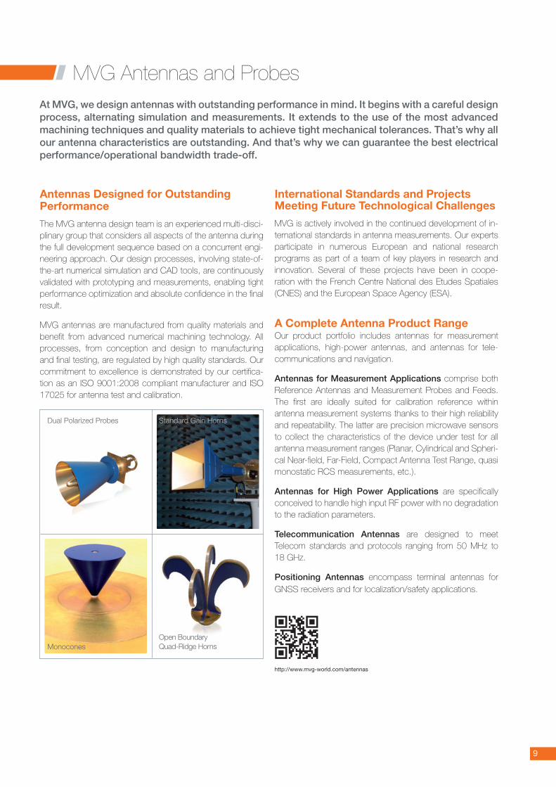
Dual Polarized Probes Standard Gain Horns
http://www.mvg-world.com/antennas
MonoconesOpen Boundary Quad-Ridge Horns
10
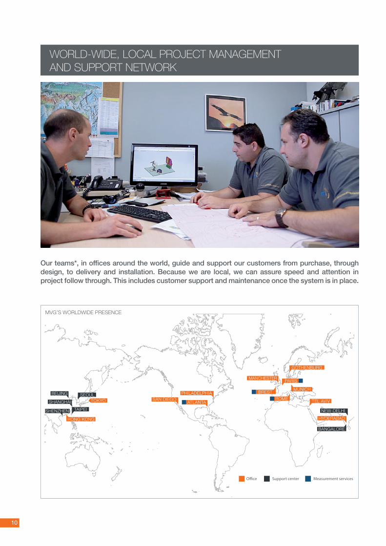
WORLD-WIDE, LOCAL PROJECT MANAGEMENT AND SUPPORT NETWORK
Our teams*, in offices around the world, guide and support our customers from purchase, through design, to delivery and installation. Because we are local, we can assure speed and attention in project follow through. This includes customer support and maintenance once the system is in place.
MANCHESTER
O�ce Support center Measurement services
MVG’S WORLDWIDE PRESENCE

11
Antenna Measurement Services
AMS Certification Assistance
Training
EMC Certification Services
Project Management and Consulting
Facility Upgrade Services
Post Warranty Services
Relocation Services
➊ CONSULTATION• Discussions• Site survey & facility assessment• Solution assessment
➋ DESIGN• Project planning• Chamber configuration• System requirement analysis• Block diagrams• Power & error budget• Mechanical & RF simulations
➌ PRODUCTION• Production planning • Quality control through dedicated procedures
➍ INTEGRATION• Interface development• Integration testing
➎ INSTALLATION• Equipment installations • Testing • Calibration• Certification
➏ SUPPORT• Remote & on-site technical support • Periodic calibration • Refurbishment• Upgrades• Training• Relocations• Post-warranty plans
http://www.mvg-world.com/services
MVG Services
12
Multi-probe systems
Our multi-probe systems utilize MV-ScanTM technology to conduct fast, accurate and smart antenna measurements and radome tests. MV-ScanTM Technology is integrated in all multi-probe systems, allowing major improvements in terms of measurement speed.
Single-probe systems
Our single-probe systems are able to control in real-time up to 4 axes in parallel in near-field and far-field measurements. The systems utilize the MV-CorTM correction table service and a high speed linear motor to improve accuracy and measu-rement speed.
Our single-probe systems are the solution for measurement of high frequency bands - above 18 GHz.
When you purchase a single-probe system, know that you can upgrade your system to a multi-probe or hybrid system.
Hybrid systems
MVG is at the forefront of the industry with the launch of hybrid systems. Combining multi-probe and single-probe technolo-gies, hybrid systems are the best compromise of accuracy, flexibility and measurement speed.
The hybrid systems consist of the best of two technologies:
• High speed electronically scanned multi-probe array • Fast and accurate electro-mechanical systems for higher
frequency bands of up to 400 GHz offered by single-probe
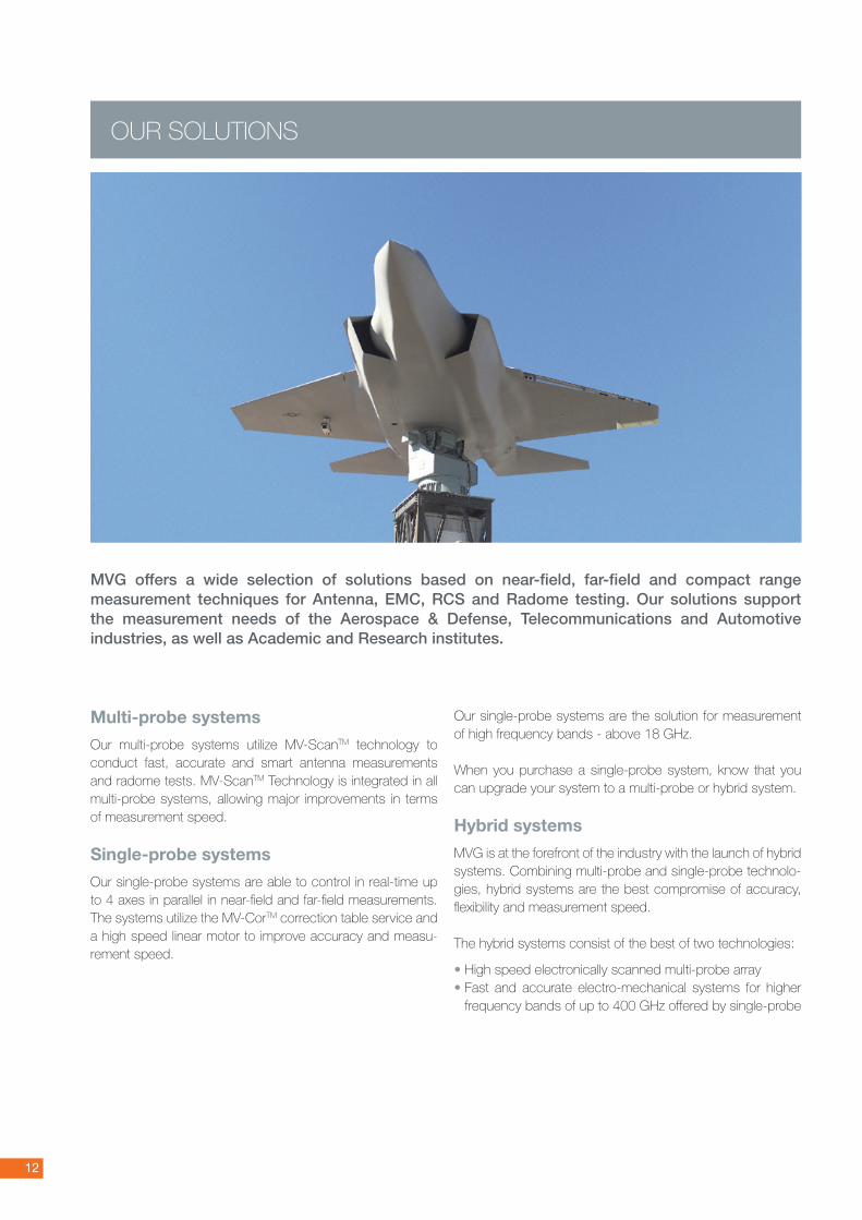
OUR SOLUTIONS
MVG offers a wide selection of solutions based on near-field, far-field and compact range measurement techniques for Antenna, EMC, RCS and Radome testing. Our solutions support the measurement needs of the Aerospace & Defense, Telecommunications and Automotive industries, as well as Academic and Research institutes.
13
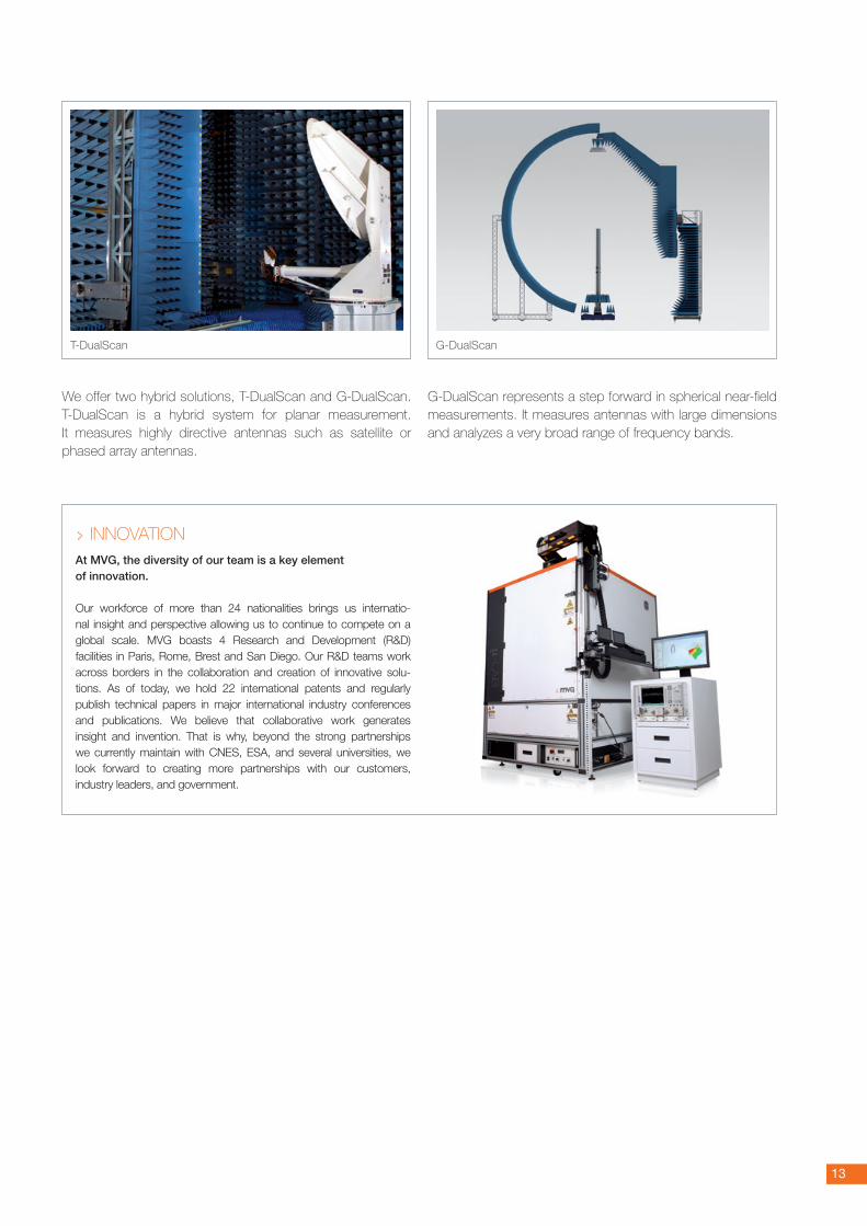
We offer two hybrid solutions, T-DualScan and G-DualScan. T-DualScan is a hybrid system for planar measurement. It measures highly directive antennas such as satellite or phased array antennas.
G-DualScan represents a step forward in spherical near-field measurements. It measures antennas with large dimensions and analyzes a very broad range of frequency bands.
T-DualScan G-DualScan
> INNOVATION
At MVG, the diversity of our team is a key element of innovation.
Our workforce of more than 24 nationalities brings us internatio-nal insight and perspective allowing us to continue to compete on a global scale. MVG boasts 4 Research and Development (R&D) facilities in Paris, Rome, Brest and San Diego. Our R&D teams work across borders in the collaboration and creation of innovative solu-tions. As of today, we hold 22 international patents and regularly publish technical papers in major international industry conferences and publications. We believe that collaborative work generates insight and invention. That is why, beyond the strong partnerships we currently maintain with CNES, ESA, and several universities, we look forward to creating more partnerships with our customers, industry leaders, and government.
14
Name WaveStudio OTA measurement suite
959 Spectrum Midas MV-Echo Insight SatEnv
Applications
Data acquisition & analysis - OTA measurements
Data acquisition & analysis - Antenna measurement
Data acquisition & analysis - Antenna measurement
Echo reduction of antenna measurements
Post-processing and model sourcing for numerical computations in large EM problems
Measurement control, data acquisition and data processing-antenna measurement
Objective
• OTA measurements & Analysis• Setup and batching
in pre-measurement module• Provide fast & fl exible accurate
OTA measurement results
• Automation of the measurement • Provide common interface
for both DA and Ana• Analysis & presentation of results
• Automation of the measurement• Display measurement during
acquisition process• Analysis & presentation of results
• Filtering out echos in near-fi eld and far-fi eld measurements
• Optimization of the AUT minimum sphere
• Improvement of accuracy in antenna measurerment performance
• Compute equivalent source models
• Provide diagnosis of antenna radiation pattern
• Detect spurious radiation
• Manage measurement campaigns• Control various axes • Provide data visualization
& processing for analysis
Keyfeatures
• Batching capabilities• 3 modules, 1 interface• Supports all current protocols• TRP, TIS, A-GPS, conducted, +
• Quicklook plots • Multi-threaded kernal• Enhanced calibration capabilities - Rotatable 3D plots - Customizable interface
• Multi-axis control with linked axis capabilities
• Continuous step or spin measurement mode
• Unlimited shape area - 2D or 3D plots - Zooming, markers, - Comparison of pattern in different
fi les
• Echo fi lters for NF and FF• Modal fi ltering algorithms• Modules in the Spherical Wave
Harmonics domain
• Computation of authentic EM current distributions and extreme near-fi eld of antenna
• 3D equivalent current distribution reconstruction
• Defi nition of 3D surface• Currents to near-fi eld
transformation
• Controllers for mechanical axes positioning
• Frequency axes for spectrum sweeping
• Data processing NF to FF - average, minimum, maximum, standard deviation gain,...
• External Library (DLL) additions possible
Websiteproductpage
Quick Guide: MVG Software for Antenna Measurement
http://www.mvg-world.com/wavestudio
http://www.mvg-world.com/959_Spectrum
http://www.mvg-world.com/midas
15
Name WaveStudio OTA measurement suite
959 Spectrum Midas MV-Echo Insight SatEnv
Applications
Data acquisition & analysis - OTA measurements
Data acquisition & analysis - Antenna measurement
Data acquisition & analysis - Antenna measurement
Echo reduction of antenna measurements
Post-processing and model sourcing for numerical computations in large EM problems
Measurement control, data acquisition and data processing-antenna measurement
Objective
• OTA measurements & Analysis• Setup and batching
in pre-measurement module• Provide fast & fl exible accurate
OTA measurement results
• Automation of the measurement • Provide common interface
for both DA and Ana• Analysis & presentation of results
• Automation of the measurement• Display measurement during
acquisition process• Analysis & presentation of results
• Filtering out echos in near-fi eld and far-fi eld measurements
• Optimization of the AUT minimum sphere
• Improvement of accuracy in antenna measurerment performance
• Compute equivalent source models
• Provide diagnosis of antenna radiation pattern
• Detect spurious radiation
• Manage measurement campaigns• Control various axes • Provide data visualization
& processing for analysis
Keyfeatures
• Batching capabilities• 3 modules, 1 interface• Supports all current protocols• TRP, TIS, A-GPS, conducted, +
• Quicklook plots • Multi-threaded kernal• Enhanced calibration capabilities - Rotatable 3D plots - Customizable interface
• Multi-axis control with linked axis capabilities
• Continuous step or spin measurement mode
• Unlimited shape area - 2D or 3D plots - Zooming, markers, - Comparison of pattern in different
fi les
• Echo fi lters for NF and FF• Modal fi ltering algorithms• Modules in the Spherical Wave
Harmonics domain
• Computation of authentic EM current distributions and extreme near-fi eld of antenna
• 3D equivalent current distribution reconstruction
• Defi nition of 3D surface• Currents to near-fi eld
transformation
• Controllers for mechanical axes positioning
• Frequency axes for spectrum sweeping
• Data processing NF to FF - average, minimum, maximum, standard deviation gain,...
• External Library (DLL) additions possible
Websiteproductpage
http://www.mvg-world.com/mv-echo
http://www.mvg-world.com/insight
http://www.mvg-world.com/satenv
SatEnv
Quality Products and Services, the Key to Customer Satisfaction
Satisfi ed Customers on Three Continents
A portfolio of key accounts:
AIRBUS, BAE, BMW, BOEING, CNES, EADS, ERICSSON, ESA, HUAWEI, IAI, INTEL, LOCKHEED MARTIN, NASA, NOKIA, NORTHROP GRUMMAN, PANASONIC, QUAL-COMM, RAYTHEON, RENAULT, SAMSUNG and ZTE
QUALITY MANAGEMENT AT MVG
MVG is ISO 9001: 2008 certified. This certificate ensures that:
• Our products meet customer and applicable regulatory requirements
• Our processes aim at continuous improvement of customer satisfaction and conformity of our products to requirements
CERTIFICATION COMPLIANCE
Our systems are particularly well suited for testing wire-less devices in active mode. It is our company strategy to follow the evolution of the different telecommunica-tion protocols and to be present in the standardization committees to actively contribute to the drafting of the test plan.
• CTIA (International Association for the Wireless Telecommunication Industry)
We are a member of the CTIA working groups, focusing on the Over the Air measurement protocols for the CDMA, GSM, UMTS, TDMA and analogue protocols. Both our SG 24 and SG 64 can perform measurements in compliance with the CTIA standards.
In addition, our U.S. laboratory in Atlanta has received the CTIA 3.1 accreditation and our SG systems are on the CTIA Authorized Equipment List.
Several of our customers, including test laboratories, mobile manufacturers and antenna design houses have CTIA accre-dited systems, using MVG equipment.
Our own CTIA authorized test and calibration lab in Kennesaw, GA (USA) also offers measurement calibration and services.
We are also part of the CTIA’s Converged Devices ad-hoc group to integrate Wi-Fi into the CTIA OTA test plan.
ISO 17025 certifi cation and A2L accreditation*concerning calibration and electrical quality of our measurement facilities. * The scope of accreditation is location-dependent and does not include the
entire scope of MVG activities.
• COST (European Cooperation in Science and Tech-nology) and COST IC1004 IC1004 (Cooperative Radio Communications for Green Smart Environments)
We have been part of COST273, and COST2100 over the past years and now are part of the COSTIC1004 TWGO (Topical Working Group on MIMO OTA) in charge of supporting the Wireless Industry in developing the standards for testing new generation wireless terminals.
• 3GPP (3rd Generation Partnership Project)
We are part of the 3GPP working group, the scope of which is to produce technical specifi cations and technical reports for a 3rd generation mobile system. The 3 GPP covers all GSM (including GPRS and EDGE) and W-CDMA specifications (UMTS).
2246.02 Calibration 2246.01 Electrical
16
17
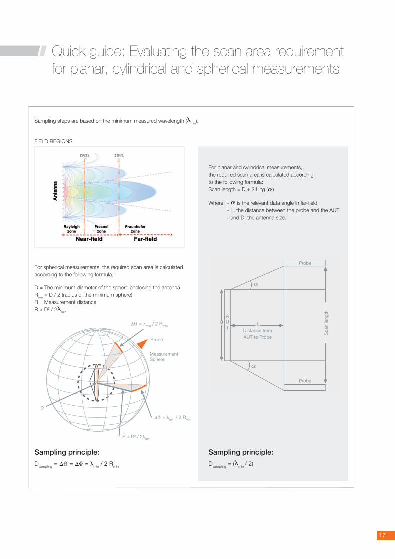
Sampling steps are based on the minimum measured wavelength (lmin).
Probe
D
DV = lmin / 2 Rmin
DF = lmin / 2 Rmin
R > D2 / 2lmin
MeasurementSphere
For spherical measurements, the required scan area is calculated according to the following formula:
D = The minimum diameter of the sphere enclosing the antennaRmin = D / 2 (radius of the minimum sphere)R = Measurement distanceR > D2 / 2lmin
Sampling principle:
Dsampling = DV = DF = lmin / 2 Rmin
FIELD REGIONS
Probe
Probe
LDistance fromAUT to Probe
Sca
n le
ngth
DAUT
a
a
For planar and cylindrical measurements, the required scan area is calculated according to the following formula: Scan length = D + 2 L tg (a)
Where: - a is the relevant data angle in far-fi eld - L, the distance between the probe and the AUT - and D, the antenna size.
Sampling principle:
Dsampling = (lmin / 2)
Quick guide: Evaluating the scan area requirement for planar, cylindrical and spherical measurements
18
Systemname StarLab StarMIMO SG 32 SG 24 SG 64 SG 128 SG 3000 F SG 3000 M SG 4100 F Starbot 4200 Starbot 4300
Applications
• Antenna measurement
• Linear array antenna measurement
• OTA testing
• MIMO OTA testing• MIMO measurement
• Antenna measurement
• OTA testing • MIMO measurement
• Antenna measurement
• OTA testing• MIMO measurement• Linear array antenna
measurement• CTIA certifi able
measurement
• Antenna measurement
• OTA testing• MIMO measurement• Linear array antenna
measurement• CTIA certifi able
measurement
• Antenna measurement
• Linear array antenna measurement
• Sub-system antenna measurement
• Vehicle testing • Vehicle testing • Radome testing • Radar antenna testing
• Aircraft/ vehicle in situ antenna characterization
• Radar antenna testing
Technology
• Near-fi eld / Spherical
• Near-fi eld / Cylindrical
• MIMO • Near-fi eld / Spherical
• Near-fi eld / Spherical
• Far-fi eld
• Near-fi eld / Spherical
• Far-fi eld
• Near-fi eld / Spherical
• Far-fi eld
• Near-fi eld / Spherical
• Near-fi eld / Spherical
• Near-fi eld / Spherical
• Near-fi eld / Spherical
• Near-field / Spherical
Frequencybands
• StarLab 6 GHz: 650 MHz to 6 GHz
• StarLab 18 GHz: 650 MHz to 18 GHz
• 400 MHz to 6 GHz(depending on the specifi cation of the spatial channel emulator)
• SG 32 - 6 GHz: 800 MHz to 6 GHz
• SG 32 - 18 GHz: 800 MHz to 18 GHz
• SG 24 - Compact: 650 MHz to 6 GHz
• SG 24 - Standard: 400 MHz to 6 GHz
• SG 24 - Large: 400 MHz to 6 GHz
• SG 64 - Compact, SG 64 - Standard and SG 64 - Large: 400 MHz to 6 GHz
• SG 64 - 18 GHz: 400 MHz to 18 GHz
• SG 64 - LF: 70 MHz to 6 GHz
• SG128 - 6 GHz: 400 MHz to 6 GHz
• SG 128 - 18 GHz: 400 MHz to 18 GHz
• 70 MHz to 6 GHz • 400 MHz to 6 GHz • System optimized for X band but customizable from 70 MHz to 18 GHz (up to 40 GHz with single-probe)
• System optimized for S band but operational over 1 to 6 GHz or 1 to 18 GHz
• 500 MHz - 18 GHz
MaxsizeofDUT
• 45 cm for spherical set-up
• 2.7m x 45 cm for cylindrical set up
• Specific lengths available upon request for cylindrical set-up
• Depending on the number of probes
• 84 cm • 1.79 m for SG 24 - L
• 2.73 m for SG 64 - L
• 4.16 m • 2.4 m x 6 m (W x L) • 2.4 m x 6 m (W x L) • 2.40 m Ø x 1.0 m deep
• 1 m x 1 m • N.A
Antennadirectivity• Low to High • Low to High • Low to High • Low to High • Low to High • Low to High • Low to High • Low to High • Low to High • Low to High • Low to High
Measurementspeed• 10 times faster
than standard• 10 times faster
than standard• 10 times faster
than standard• 10 times faster
than standard• 10 times faster
than standard• 10 times faster
than standard• 10 times faster
than standard• 10 times faster
than standard• 10 times faster
than standard• 10 times faster
than standard• 10 times faster
than standard
Industries
• Aerospace & Defense
• Telecom• Automotive • Academic &
Research institutes
• Telecom• Aerospace
& Defense• Automotive
• Aerospace & Defense
• Telecom• Automotive • Academic &
Research institutes
• Aerospace & Defense
• Telecom• Automotive • Academic &
Research institutes
• Aerospace & Defense
• Telecom • Automotive
• Aerospace & Defense
• Telecom • Automotive
• Aerospace & Defense
• Automotive
• Aerospace & Defense
• Automotive
• Aerospace & Defense
• Aerospace & Defense
• Aerospace & Defense
Websiteproductpage
Multi-Probe
Quick Guide: MVG Antenna Measurement Solutions
http://www.mvg-world.com/starlab
http://www.mvg-world.com/fr/StarMIMO
http://www.mvg-world.com/fr/SG_32
http://www.mvg-world.com/fr/SG_24
http://www.mvg-world.com/fr/SG_64
19
Systemname StarLab StarMIMO SG 32 SG 24 SG 64 SG 128 SG 3000 F SG 3000 M SG 4100 F Starbot 4200 Starbot 4300
Applications
• Antenna measurement
• Linear array antenna measurement
• OTA testing
• MIMO OTA testing• MIMO measurement
• Antenna measurement
• OTA testing • MIMO measurement
• Antenna measurement
• OTA testing• MIMO measurement• Linear array antenna
measurement• CTIA certifi able
measurement
• Antenna measurement
• OTA testing• MIMO measurement• Linear array antenna
measurement• CTIA certifi able
measurement
• Antenna measurement
• Linear array antenna measurement
• Sub-system antenna measurement
• Vehicle testing • Vehicle testing • Radome testing • Radar antenna testing
• Aircraft/ vehicle in situ antenna characterization
• Radar antenna testing
Technology
• Near-fi eld / Spherical
• Near-fi eld / Cylindrical
• MIMO • Near-fi eld / Spherical
• Near-fi eld / Spherical
• Far-fi eld
• Near-fi eld / Spherical
• Far-fi eld
• Near-fi eld / Spherical
• Far-fi eld
• Near-fi eld / Spherical
• Near-fi eld / Spherical
• Near-fi eld / Spherical
• Near-fi eld / Spherical
• Near-field / Spherical
Frequencybands
• StarLab 6 GHz: 650 MHz to 6 GHz
• StarLab 18 GHz: 650 MHz to 18 GHz
• 400 MHz to 6 GHz(depending on the specifi cation of the spatial channel emulator)
• SG 32 - 6 GHz: 800 MHz to 6 GHz
• SG 32 - 18 GHz: 800 MHz to 18 GHz
• SG 24 - Compact: 650 MHz to 6 GHz
• SG 24 - Standard: 400 MHz to 6 GHz
• SG 24 - Large: 400 MHz to 6 GHz
• SG 64 - Compact, SG 64 - Standard and SG 64 - Large: 400 MHz to 6 GHz
• SG 64 - 18 GHz: 400 MHz to 18 GHz
• SG 64 - LF: 70 MHz to 6 GHz
• SG128 - 6 GHz: 400 MHz to 6 GHz
• SG 128 - 18 GHz: 400 MHz to 18 GHz
• 70 MHz to 6 GHz • 400 MHz to 6 GHz • System optimized for X band but customizable from 70 MHz to 18 GHz (up to 40 GHz with single-probe)
• System optimized for S band but operational over 1 to 6 GHz or 1 to 18 GHz
• 500 MHz - 18 GHz
MaxsizeofDUT
• 45 cm for spherical set-up
• 2.7m x 45 cm for cylindrical set up
• Specific lengths available upon request for cylindrical set-up
• Depending on the number of probes
• 84 cm • 1.79 m for SG 24 - L
• 2.73 m for SG 64 - L
• 4.16 m • 2.4 m x 6 m (W x L) • 2.4 m x 6 m (W x L) • 2.40 m Ø x 1.0 m deep
• 1 m x 1 m • N.A
Antennadirectivity• Low to High • Low to High • Low to High • Low to High • Low to High • Low to High • Low to High • Low to High • Low to High • Low to High • Low to High
Measurementspeed• 10 times faster
than standard• 10 times faster
than standard• 10 times faster
than standard• 10 times faster
than standard• 10 times faster
than standard• 10 times faster
than standard• 10 times faster
than standard• 10 times faster
than standard• 10 times faster
than standard• 10 times faster
than standard• 10 times faster
than standard
Industries
• Aerospace & Defense
• Telecom• Automotive • Academic &
Research institutes
• Telecom• Aerospace
& Defense• Automotive
• Aerospace & Defense
• Telecom• Automotive • Academic &
Research institutes
• Aerospace & Defense
• Telecom• Automotive • Academic &
Research institutes
• Aerospace & Defense
• Telecom • Automotive
• Aerospace & Defense
• Telecom • Automotive
• Aerospace & Defense
• Automotive
• Aerospace & Defense
• Automotive
• Aerospace & Defense
• Aerospace & Defense
• Aerospace & Defense
Websiteproductpage
http://www.mvg-world.com/fr/SG_128
http://www.mvg-world.com/fr/SG_3000M
http://www.mvg-world.com/fr/SG_3000F
http://www.mvg-world.com/fr/SG_4100F
http://www.mvg-world.com/fr/Starbot_4200
http://www.mvg-world.com/fr/Starbot_4300
Quick Guide: MVG Antenna Measurement Solutions
20
Single-Probe
Systemname µ-Lab CR-MCompact
RangeFScan TScan HScan Systemname T-DualScan G-DualScan
Applications
• Chip measurements• Miniature
connectorized antenna measurements
• Measurements of laptops and other devices
• Characterization of small and high gain antennas
• Millimeter wave applications
• Production testing
• Antenna measurement
• Radome measurement
• RCS measurement
• High gain antenna testing
• Near-fi eld focused antenna testing,
• Phased array antenna measurement
• Array illumination assessment
• Array element failure analysis
• Phased array antenna testing
• High gain antenna testing
• Near-field focused antenna testing
• Array illumination assessment
• Array element failure analysis
• Space-borne antenna measurements
• Payload testing• Phased array
antenna testing• High gain antenna
testing• Array illumination
assessment• Array element
failure
Applications
• Antenna measurement
• Pulsed measurement
• Phased array antenna measurement
• Antenna measurement
• Pulsed measurement
• Phased array antenna measurement
Technology
• Near-field / Spherical
• Far-field / Spherical
• Compact Range • Compact Range • Near-fi eld / Planar• Optional:
Near-fi eld / SphericalNear-fi eld / Cylindrical
• Near-field / Planar • Optional:
Near-fi eld / SphericalNear-fi eld / Cylindrical
• Near-fi eld / Planar • Near-fi eld /
cylindrical or Spherical - optional Technology
• Near-fi eld / Planar• Near-fi eld /
Cylindrical
• Near-fi eld / Spherical
• Far-fi eld / Spherical
Frequencybands
• 50 - 110 GHz• 18 - 50 GHz
optional• Other bands
possible upon request
• CR-M12: 8 - 110 GHz
• CR-M14: 4 - 110 GHz
• CR-M16: 4 - 110 GHz
• Small: 2 - 110 GHz*• Medium:
700 MHz - 110 GHz*• Large:
700 MHz - 110 GHz*
• 100 MHz - 110 GHz • 100 MHz - 110 GHz • 100 MHz - 110 GHz
Frequencybands
• Single-probe: 800 MHz - 110 GHz
• Multi-probe: 800 MHz - 18 GHz
• Multi-probe: 70 - 800 MHz upon request
• Single-probe: 200 MHz - 18 GHz, divided in sub-bands (up to 40 GHz upon request)
• Multi-probe: 400 MHz - 6 GHz (400 MHz - 18 GHz or 70 - 400 MHz upon request)
MaxsizeofDUT
• On centered support column: as large as a standard laptop
• On offset column for chip measure-ments: 5 cm x 5 cm (chipset)
• Up to 50 cm diameter
• During full rotation of the DUT, the radiating parts of the DUT must stay within the quiet zone
• Depending on the scan length and antenna length
• Depending on the scan length and antenna length
• Depending on the scan length and antenna length
MaxsizeofDUT
• Depending on the scan length and antenna length
• 7 m diameter
Antennadirectivity• Low to High • High • Medium to High • High • High • High
Antennadirectivity• High • Low to High
Measurementspeed
• Standard • Standard • Standard • Standard • Standard • Standard
Measurementspeed
• Multi-Probe: 10 times faster than standard
• Single-probe: Standard
• Multi-Probe: 10 times faster than standard
• Single-probe: Standard
Industries
• Telecom• Academic &
Research institutes
• Aerospace & Defense
• Telecom • Automotive
• Aerospace & Defense
• Telecom • Automotive
• Aerospace & Defense
• Telecom • Automotive • Academic &
Research institutes
• Aerospace & Defense
• Telecom • Automotive
• Aerospace & Defense
• Telecom • Research institutes Industries
• Aerospace & Defense
• Telecom
• Aerospace & Defense
• Telecom
Websiteproductpage Websiteproductpage
http://www.mvg-world.com/fr/u-Lab
http://www.mvg-world.com/fr/CR-M
http://www.mvg-world.com/fr/Compact_Range
http://www.mvg-world.com/fr/FScan
http://www.mvg-world.com/fr/TScan
21
Hybrid
http://www.mvg-world.com/fr/HScan
http://www.mvg-world.com/fr/T-DualScan
http://www.mvg-world.com/fr/G-DualScan
Systemname µ-Lab CR-MCompact
RangeFScan TScan HScan Systemname T-DualScan G-DualScan
Applications
• Chip measurements• Miniature
connectorized antenna measurements
• Measurements of laptops and other devices
• Characterization of small and high gain antennas
• Millimeter wave applications
• Production testing
• Antenna measurement
• Radome measurement
• RCS measurement
• High gain antenna testing
• Near-fi eld focused antenna testing,
• Phased array antenna measurement
• Array illumination assessment
• Array element failure analysis
• Phased array antenna testing
• High gain antenna testing
• Near-field focused antenna testing
• Array illumination assessment
• Array element failure analysis
• Space-borne antenna measurements
• Payload testing• Phased array
antenna testing• High gain antenna
testing• Array illumination
assessment• Array element
failure
Applications
• Antenna measurement
• Pulsed measurement
• Phased array antenna measurement
• Antenna measurement
• Pulsed measurement
• Phased array antenna measurement
Technology
• Near-field / Spherical
• Far-field / Spherical
• Compact Range • Compact Range • Near-fi eld / Planar• Optional:
Near-fi eld / SphericalNear-fi eld / Cylindrical
• Near-field / Planar • Optional:
Near-fi eld / SphericalNear-fi eld / Cylindrical
• Near-fi eld / Planar • Near-fi eld /
cylindrical or Spherical - optional Technology
• Near-fi eld / Planar• Near-fi eld /
Cylindrical
• Near-fi eld / Spherical
• Far-fi eld / Spherical
Frequencybands
• 50 - 110 GHz• 18 - 50 GHz
optional• Other bands
possible upon request
• CR-M12: 8 - 110 GHz
• CR-M14: 4 - 110 GHz
• CR-M16: 4 - 110 GHz
• Small: 2 - 110 GHz*• Medium:
700 MHz - 110 GHz*• Large:
700 MHz - 110 GHz*
• 100 MHz - 110 GHz • 100 MHz - 110 GHz • 100 MHz - 110 GHz
Frequencybands
• Single-probe: 800 MHz - 110 GHz
• Multi-probe: 800 MHz - 18 GHz
• Multi-probe: 70 - 800 MHz upon request
• Single-probe: 200 MHz - 18 GHz, divided in sub-bands (up to 40 GHz upon request)
• Multi-probe: 400 MHz - 6 GHz (400 MHz - 18 GHz or 70 - 400 MHz upon request)
MaxsizeofDUT
• On centered support column: as large as a standard laptop
• On offset column for chip measure-ments: 5 cm x 5 cm (chipset)
• Up to 50 cm diameter
• During full rotation of the DUT, the radiating parts of the DUT must stay within the quiet zone
• Depending on the scan length and antenna length
• Depending on the scan length and antenna length
• Depending on the scan length and antenna length
MaxsizeofDUT
• Depending on the scan length and antenna length
• 7 m diameter
Antennadirectivity• Low to High • High • Medium to High • High • High • High
Antennadirectivity• High • Low to High
Measurementspeed
• Standard • Standard • Standard • Standard • Standard • Standard
Measurementspeed
• Multi-Probe: 10 times faster than standard
• Single-probe: Standard
• Multi-Probe: 10 times faster than standard
• Single-probe: Standard
Industries
• Telecom• Academic &
Research institutes
• Aerospace & Defense
• Telecom • Automotive
• Aerospace & Defense
• Telecom • Automotive
• Aerospace & Defense
• Telecom • Automotive • Academic &
Research institutes
• Aerospace & Defense
• Telecom • Automotive
• Aerospace & Defense
• Telecom • Research institutes Industries
• Aerospace & Defense
• Telecom
• Aerospace & Defense
• Telecom
Websiteproductpage Websiteproductpage
22
Array part numbers are composed of the following fi elds[Distance] - [Probes] - [Number of Probes] - [Distance between probes] according to these rules:
Field Linear array Circular array
[Distance] Distance between fi rst and last probes, in mm Internal diameter in mm
[Probes] The probe model or list of probe models (if probes are interleaved) comprising the array, selected from: • DP70-450 • DP400-6000 • DP6000-18000 And separated by “/” if necessary
[Number of Probes] The number of each probe model separated by "/" if necessary
[Distance between probes] The distance between probes in mm The angle between probes in degrees
Single-probe systems
Each Single-probe system has its own unique model number to facilitate the ordering process. For example, in the CR-M series, there are CR-M12, CR-M16, CR-M20. If customization is required, your local sales representative will provide you with the list of referenced components.
Multi-probe systems
Our multi-probe system part numbers include the system model name and the probe array part numbers, according to the following scheme: Model-{Array1}-{Array2}-…
The model fi eld can have the following values
• StarLab
• StarMIMO
• SG 32
• SG 24
• SG 64
• SG 128
• SG 3000F
• SG 3000M
• SG 4100F
• StarBot 4200
• StarBot 4300
• T-DualScan
• G-DualScan
Ordering information
23
Sample ordering code:• StarLab 6 GHz: StarLab-{[900]-[DP400-6000]-[15]-[22.5]}• StarLab 18 GHz: StarLab-{[900]-[DP400-6000/DP6000-18000]-[15/14]-[11.25]}• SG 64-L: SG64-{[4200]-[DP400-6000]-[63]-[5.29]}• …
* Interleaved arrays are considered one array.
Hybrid systems
A hybrid system consists of both a multi-probe and a single-probe configuration. Please use the same ordering process given above for multi-probe and single-probe systems. Indicate the single probe information first, then the multi-probe information.
> WIDEBAND DUAL POLARIZED PROBES
Three types of probes and several sizes of supporting structures are available for measurements covering the 70 MHz to 18 GHz frequency range. Probes designed to reach 40 GHz are currently under development. Meanwhile, 40 GHz systems can be delivered using a combination of single probe and MVG's multi-probe technology. The wide bandwidth of our systems offers an additional advantage of increased speed in the ability to measure wide band and multi-band antennas without changing probes.
Three probes that can be interleaved*
Product DP 70-450 DP 200-6000 DP 400-6000 DP 6000-10000 DP 6000-18000 DP 200-10000 reference
Frequency band 0.07 GHz - 0.45 GHz 0.4 GHz - 6.0 GHz 6.0 GHz - 18 GHz
Extended frequency band 0.2G Hz - 6.0 GHz 6.0 GHz - 10.0 GHz 0.2 GHz - 10.0 GHz
Aperture size 247 mm x 247 mm 63 mm x 63 mm 22 mm x 22 mm
Ordering information
© M
ICR
OW
AV
E V
ISIO
N 2
016
- V
01 -
Gra
phi
c d
esig
n: w
ww
.ate
lierm
aup
oux.
com
- ©
pho
tos:
all
right
s re
serv
ed.
MVG - About Us
The Microwave Vision Group (MVG) has developed unique expertise in the visualization of electromagnetic waves. These waves are at the heart of our daily lives: smartphones, computers, tablets, cars, trains, planes - these devices and vehicles would not work without them. MVG expertise brings measurement solutions to R&D teams for the characterization of antennas and their performance within these devices, and chamber solutions for EMC testing. MVG innovation remains focused on supplying R&D teams with the most advanced EMF measurement technology on the market.
MVG - Corporate HQ
47, boulevard Saint Michel75005 ParisFRANCE
Tel: +33 (0)1 75 77 58 50
MVG Industries
17 avenue de Norvège91140 Villebon-sur-YvetteFRANCE
Tel: +33 (0)1 69 29 02 47
MVG Industries Bretagne
Technopole Brest Iroise, Z.I. du Vernis, 225 rue Pierre Rivoalon, 29200 Brest FRANCE
Tel: +33 (0)2 98 05 13 34
Orbit/FR Germany
ORBIT/FR GermanyJ. S. Bach-Str. 11 85591 Vaterstetten GERMANY
Tel: +49 (0)810 699 6060
MVG Sweden
P.O. Box 35 44121 Alingsas GothenburgSWEDEN
Tel: +46 31 402 430
Orbit/FR Israel
1 Gesher Ha-Ets St., P.O. Box 12096, Emek Hefer Industrial Park, 38777-01 Emek HeferISRAEL
Tel: +972 74 713 0130
MVG Italy
Via Castelli Romani, 59 00040 Pomezia (Rome) ITALY
Tel: +39 06 89 99 53 11
Rainford EMC Systems Limited
Unit 400,Haydock Lane, Haydock WA11 9TH UNITED KINGDOM
Tel: +44 (0)1 942 296 190
MVG India
N° 414 Cunnigham Road Level 4 Prestige Centre Point, 560052 Bangalore INDIA
Tel: +91 70 22 98 12 16
MVG Hong-Kong
Suite 702, 7th floor Cyberport 1100 Cyberport RoadPok Fu LamHong Kong SARCHINA
Tel: +85 229 896 128
MVG Japan
#101 Confort Musashi- Nakahara, 2-10-32, Shimokodanaka,Nakahara-ku, Kawasaki-city211-0041 Kanagawa JAPAN
Tel: +81 44 948 9301
Orbit/FR’s Corporate HQ
506 Prudential Road Horsham, PA 19044 UNITED STATES
Tel: +1(215) 674 5100
MVG, Inc
2105 Barrett Park Dr., Suite 104Kennesaw, GA 30144UNITED STATES
Tel: +1 678 797 9172
AEMI
1320 Air Wing Road, suite 101Otay Mesa, CA 92154 UNITED STATES
Tel: +1 (619) 449 9492
❚ Production site in Israel
❚ Research and Production center in France
Contact your local sales representative for more [email protected]