Embed Size (px)
Citation preview
Antenna Materials and Accessories 20-1
This chapter contains information on materials amateurs use to construct antennas—what typesof material to look for in a particular application, tips on working with and using various mate-rials. Chapter 21 contains information on where to purchase these materials.
Basically, antennas for MF, HF, VHF and the lower UHF range consist simply of one or more conduc-tors that radiate (or receive) electromagnetic waves. However, an antenna system must also include somemeans to support those conductors and maintain their relative positions—the boom for a Yagi antenna andthe halyards for a wire dipole, for example. In this chapter we’ll look at materials for those applications, too.Structural supports such as towers, masts, poles, etc are discussed in Chapter 22.
There are two main types of material used for antenna conductors, wire and tubing. Wire antennasare generally simple and therefore easier to construct, although some arrays of wire elements can be-come rather complex. When tubing is required, aluminum tubing is used most often because of itslight weight. Aluminum tubing is discussed in a subsequent section of this chapter.
Wire AntennasAlthough wire antennas are relatively simple, they can constitute a potential hazard unless prop-
erly constructed. Antennas should never be run under or over public utility (telephone or power) lines.Several amateurs have lost their lives by failing to observe this precaution.
The National Electrical Code of the National Fire Protection Association contains a section on amateurstations in which a number of recommendations are made concerning minimum size of antenna wire and themanner of bringing the transmission line into the station. Chapter 1 contains more information about thiscode. The code in itself does not have the force of law, but it is frequently made a part of local buildingregulations, which are enforceable. The provisions of the code may also be written into, or referred to, in fireand liability insurance documents.
The RF resistance of copper wire increases as the size of the wire decreases. However, in mosttypes of antennas that are commonly constructed of wire (even quite small wire), the radiation resis-tance will be much higher than the RF resistance, and the efficiency of the antenna will still be ad-equate. Wire sizes as small as #30, or even smaller, have been used quite successfully in the construc-tion of “invisible” antennas in areas where more conventional antennas cannot be erected. In mostcases, the selection of wire for an antenna will be based primarily on the physical properties of thewire, since the suspension of wire from elevated supports places a strain on the wire.
WIRE TYPESWire having an enamel coating is preferable to bare wire, since the coating resists oxidation and
corrosion. Several types of wire having this type of coating are available, depending on the strengthneeded. “Soft-drawn” or annealed copper wire is easiest to handle; unfortunately, it stretches con-siderably under stress. Soft-drawn wire should be avoided, except for applications where the wire willbe under little or no tension, or where some change in length can be tolerated. (For example, the lengthof a horizontal antenna fed at the center with open-wire line is not critical, although a change in lengthmay require some readjustment of coupling to the transmitter.)
“Hard-drawn” copper wire or copper-clad steel wire (also known as Copperweld) is harder to handle,
Chapter 20
Antenna Materials an d Accessories
20-2 Chapter 20
because it has a tendency to spiral when it is unrolled. These types of wire are ideal for applications wheresignificant stretch cannot be tolerated. Care should be exercised in using this wire to make sure that kinks donot develop—the wire will have a far greater tendency to break at a kink. After the coil has been unwound,suspend the wire a few feet above ground for a day or two before using it. The wire should not be recoiledbefore it is installed.
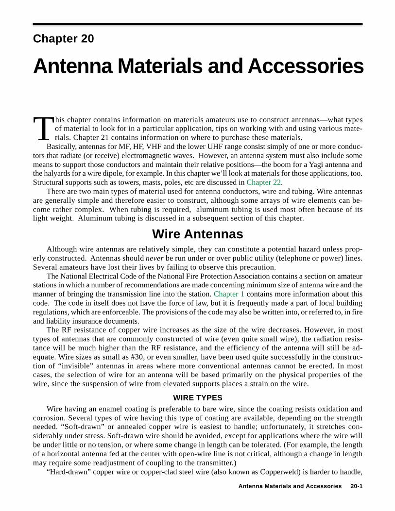
Several factors influence the choice of wire type and size. Most important to consider are the length ofthe unsupported span, the amount of sag that can be tolerated, the stability of the supports under windpressure, and whether or not an unsupported transmission line is to be suspended from the span. Table 1shows the wire diameter, current-carrying capacity and resistance of various sizes of copper wire. Table 2
Table 1Copper-Wire Table
TurnsWire per Feet Ohms Cont.-dutySize Dia Linear per per current2AWG in Dia Inch Pound 1000 ft Single Wire(B&S) Mils1 in mm Enamel Bare 25°C in Open Air
1 289.3 7.348 — 3.947 0.1264 —2 257.6 6.544 — 4.977 0.1593 —3 229.4 5.827 — 6.276 0.2009 —4 204.3 5.189 — 7.914 0.2533 —5 181.9 4.621 — 9.980 0.3195 —6 162.0 4.115 — 12.58 0.4028 —7 144.3 3.665 — 15.87 0.5080 —8 128.5 3.264 7.6 20.01 0.6405 739 114.4 2.906 8.6 25.23 0.8077 —10 101.9 2.588 9.6 31.82 1.018 5511 90.7 2.305 10.7 40.12 1.284 —12 80.8 2.053 12.0 50.59 1.619 4113 72.0 1.828 13.5 63.80 2.042 —14 64.1 1.628 15.0 80.44 2.575 3215 57.1 1.450 16.8 101.4 3.247 —16 50.8 1.291 18.9 127.9 4.094 2217 45.3 1.150 21.2 161.3 5.163 —18 40.3 1.024 23.6 203.4 6.510 1619 35.9 0.912 26.4 256.5 8.210 —20 32.0 0.812 29.4 323.4 10.35 11
21 28.5 0.723 33.1 407.8 13.05 —22 25.3 0.644 37.0 514.2 16.46 —23 22.6 0.573 41.3 648.4 20.76 —24 20.1 0.511 46.3 817.7 26.17 —25 17.9 0.455 51.7 1031 33.00 —26 15.9 0.405 58.0 1300 41.62 —27 14.2 0.361 64.9 1639 52.48 —28 12.6 0.321 72.7 2067 66.17 —29 11.3 0.286 81.6 2607 83.44 —30 10.0 0.255 90.5 3287 105.2 —31 8.9 0.227 101 4145 132.7 —32 8.0 0.202 113 5227 167.3 —33 7.1 0.180 127 6591 211.0 —34 6.3 0.160 143 8310 266.0 —35 5.6 0.143 158 10480 335 —36 5.0 0.127 175 13210 423 —37 4.5 0.113 198 16660 533 —38 4.0 0.101 224 21010 673 —39 3.5 0.090 248 26500 848 —40 3.1 0.080 282 33410 1070 —
TurnsWire per Feet Ohms Cont.-dutySize Dia Linear per per current2AWG in Dia Inch Pound 1000 ft Single Wire(B&S) Mils1 in mm Enamel Bare 25°C in Open Air
1 A mil is 0.001 inch.2 Max wire temp of 212° F and max ambient temp of 135° F.
Table 2Stressed Antenna Wire
American Recommended Tension 1 (pounds) Weight (pounds per 1000 feet)Wire Gauge Copper-clad Hard-drawn Copper-clad Hard-drawn
steel 2 copper steel 2 copper 4 495 214 115.8 126.0 6 310 130 72.9 79.5 8 195 84 45.5 50.010 120 52 28.8 31.412 75 32 18.1 19.814 50 20 11.4 12.416 31 13 7.1 7.818 19 8 4.5 4.920 12 5 2.8 3.11 Approximately one-tenth the breaking load. Might be increased 50% if end supports are firm and there is no danger of ice loading.2 Copperweld, 40% copper.
Antenna Materials and Accessories 20-3
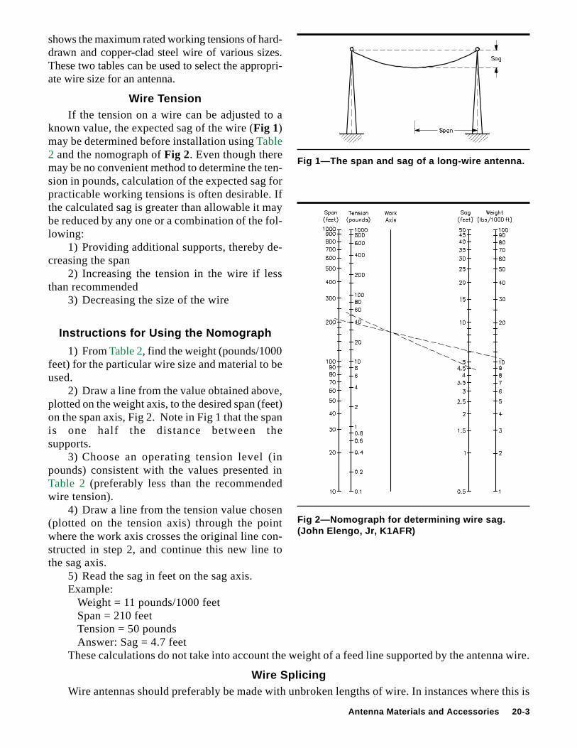
Fig 1—The span and sag of a long-wire antenna.
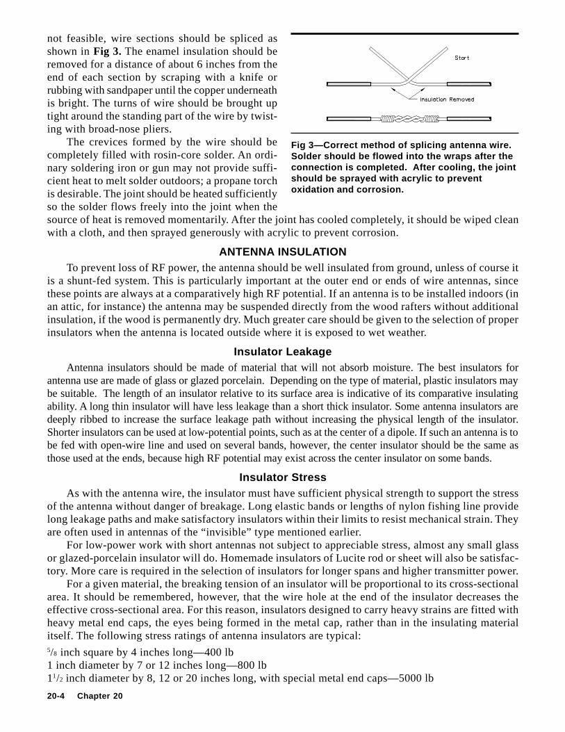
Fig 2—Nomograph for determining wire sag.(John Elengo, J r, K1AFR)
shows the maximum rated working tensions of hard-drawn and copper-clad steel wire of various sizes.These two tables can be used to select the appropri-ate wire size for an antenna.
Wire TensionIf the tension on a wire can be adjusted to a
known value, the expected sag of the wire (Fig 1)may be determined before installation using Table2 and the nomograph of Fig 2. Even though theremay be no convenient method to determine the ten-sion in pounds, calculation of the expected sag forpracticable working tensions is often desirable. Ifthe calculated sag is greater than allowable it maybe reduced by any one or a combination of the fol-lowing:
1) Providing additional supports, thereby de-creasing the span
2) Increasing the tension in the wire if lessthan recommended
3) Decreasing the size of the wire
Instructions for Using the Nomograph
1) From Table 2, find the weight (pounds/1000feet) for the particular wire size and material to beused.
2) Draw a line from the value obtained above,plotted on the weight axis, to the desired span (feet)on the span axis, Fig 2. Note in Fig 1 that the spanis one half the distance between thesupports.
3) Choose an operating tension level (inpounds) consistent with the values presented inTable 2 (preferably less than the recommendedwire tension).
4) Draw a line from the tension value chosen(plotted on the tension axis) through the pointwhere the work axis crosses the original line con-structed in step 2, and continue this new line tothe sag axis.
5) Read the sag in feet on the sag axis.Example:
Weight = 11 pounds/1000 feetSpan = 210 feetTension = 50 poundsAnswer: Sag = 4.7 feet
These calculations do not take into account the weight of a feed line supported by the antenna wire.
Wire SplicingWire antennas should preferably be made with unbroken lengths of wire. In instances where this is
20-4 Chapter 20
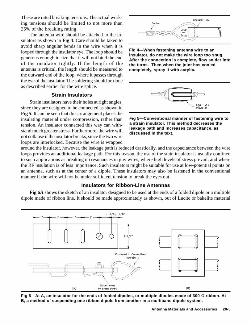
not feasible, wire sections should be spliced asshown in Fig 3. The enamel insulation should beremoved for a distance of about 6 inches from theend of each section by scraping with a knife orrubbing with sandpaper until the copper underneathis bright. The turns of wire should be brought uptight around the standing part of the wire by twist-ing with broad-nose pliers.
The crevices formed by the wire should becompletely filled with rosin-core solder. An ordi-nary soldering iron or gun may not provide suffi-cient heat to melt solder outdoors; a propane torchis desirable. The joint should be heated sufficientlyso the solder flows freely into the joint when thesource of heat is removed momentarily. After the joint has cooled completely, it should be wiped cleanwith a cloth, and then sprayed generously with acrylic to prevent corrosion.
ANTENNA INSULATIONTo prevent loss of RF power, the antenna should be well insulated from ground, unless of course it
is a shunt-fed system. This is particularly important at the outer end or ends of wire antennas, sincethese points are always at a comparatively high RF potential. If an antenna is to be installed indoors (inan attic, for instance) the antenna may be suspended directly from the wood rafters without additionalinsulation, if the wood is permanently dry. Much greater care should be given to the selection of properinsulators when the antenna is located outside where it is exposed to wet weather.
Insulator LeakageAntenna insulators should be made of material that will not absorb moisture. The best insulators for
antenna use are made of glass or glazed porcelain. Depending on the type of material, plastic insulators maybe suitable. The length of an insulator relative to its surface area is indicative of its comparative insulatingability. A long thin insulator will have less leakage than a short thick insulator. Some antenna insulators aredeeply ribbed to increase the surface leakage path without increasing the physical length of the insulator.Shorter insulators can be used at low-potential points, such as at the center of a dipole. If such an antenna is tobe fed with open-wire line and used on several bands, however, the center insulator should be the same asthose used at the ends, because high RF potential may exist across the center insulator on some bands.
Insulator StressAs with the antenna wire, the insulator must have sufficient physical strength to support the stress
of the antenna without danger of breakage. Long elastic bands or lengths of nylon fishing line providelong leakage paths and make satisfactory insulators within their limits to resist mechanical strain. Theyare often used in antennas of the “invisible” type mentioned earlier.
For low-power work with short antennas not subject to appreciable stress, almost any small glassor glazed-porcelain insulator will do. Homemade insulators of Lucite rod or sheet will also be satisfac-tory. More care is required in the selection of insulators for longer spans and higher transmitter power.
For a given material, the breaking tension of an insulator will be proportional to its cross-sectionalarea. It should be remembered, however, that the wire hole at the end of the insulator decreases theeffective cross-sectional area. For this reason, insulators designed to carry heavy strains are fitted withheavy metal end caps, the eyes being formed in the metal cap, rather than in the insulating materialitself. The following stress ratings of antenna insulators are typical:5/8 inch square by 4 inches long—400 lb1 inch diameter by 7 or 12 inches long—800 lb11/2 inch diameter by 8, 12 or 20 inches long, with special metal end caps—5000 lb
Fig 3—Correct method of splicing antenna wire.Solder should be flowed into the wraps after theconnection is completed. After cooling, the jointshould be sprayed with acrylic to preventoxidation and corrosion.
Antenna Materials and Accessories 20-5
Fig 5—Conventional manner of fastening wire toa strain insulator. This method decreases theleakage path and increases capacitance, asdiscussed in the text.
Fig 4—When fastening antenna wire to aninsulator, do not make the wire loop too snug.After the connection is complete, flow solder intothe turns. Then when the joint has cooledcompletely, spray it with acrylic.
These are rated breaking tensions. The actual work-ing tensions should be limited to not more than25% of the breaking rating.
The antenna wire should be attached to the in-sulators as shown in Fig 4. Care should be taken toavoid sharp angular bends in the wire when it islooped through the insulator eye. The loop should begenerous enough in size that it will not bind the endof the insulator tightly. If the length of theantenna is critical, the length should be measured tothe outward end of the loop, where it passes throughthe eye of the insulator. The soldering should be doneas described earlier for the wire splice.
Strain InsulatorsStrain insulators have their holes at right angles,
since they are designed to be connected as shown inFig 5. It can be seen that this arrangement places theinsulating material under compression, rather thantension. An insulator connected this way can with-stand much greater stress. Furthermore, the wire willnot collapse if the insulator breaks, since the two wireloops are interlocked. Because the wire is wrappedaround the insulator, however, the leakage path is reduced drastically, and the capacitance between the wireloops provides an additional leakage path. For this reason, the use of the stain insulator is usually confinedto such applications as breaking up resonances in guy wires, where high levels of stress prevail, and wherethe RF insulation is of less importance. Such insulators might be suitable for use at low-potential points onan antenna, such as at the center of a dipole. These insulators may also be fastened in the conventionalmanner if the wire will not be under sufficient tension to break the eyes out.
Insulators for Ribbon-Line AntennasFig 6A shows the sketch of an insulator designed to be used at the ends of a folded dipole or a multiple
dipole made of ribbon line. It should be made approximately as shown, out of Lucite or bakelite material
Fig 6—At A, an insulator for the ends of folded dipoles, or multiple dipoles made of 300- Ω ribbon. AtB, a method of suspending one ribbon dipole from another in a multiband dipole system.
20-6 Chapter 20
about 1/4 inch thick. The advantage of this arrangement is that the strain of the antenna is shared by theconductors and the plastic webbing of the ribbon, which adds considerable strength. After soldering, thescrew should be sprayed with acrylic.
Fig 6B shows a similar arrangement for suspending one dipole from another in a stagger-tuned dipolesystem. If better insulation is desired, these insulators can be wired to a conventional insulator.
PULLEYS AND HA LYARDSPulleys and halyards commonly used to raise and lower a wire antenna must also be capable of
taking the same strain as the antenna wire and insulators. Unfortunately, little specific information onthe stress ratings of most pulleys is available. Several types of pulleys are readily available atalmost any hardware store. Among these are small galvanized pulleys designed for awnings and sev-eral styles and sizes of clothesline pulleys. Heavier and stronger pulleys are those used in marine work.The factors that determine how much stress a pulley will handle include the diameter of the shaft, howsecurely the shaft is fitted into the sheath and the size and material that the frame is made of.
Another important factor to be considered in the selection of a pulley is its ability to resist corro-sion. Galvanized awning pulleys are probably the most susceptible to corrosion. While the frame orsheath usually stands up well, these pulleys usually fail at the shaft. The shaft rusts out, allowing thegrooved wheel to break away under tension.
Most good-quality clothesline pulleys are made of alloys which do not corrode readily. Since theyare designed to carry at least 50 feet of line loaded with wet clothing in stiff winds, they should beadequate for normal spans of 100 to 150 feet between stable supports. One type of clothesline pulleyhas a 4-inch diameter plastic wheel with a 1/4-inch shaft running in bronze bearings. The sheath is madeof cast or forged corrosion-proof alloy. Some look-alike low-cost pulleys of this type have an alumi-num shaft with no bearings. For antenna work, these cheap pulleys are of little long-term value.
Marine pulleys have good weather-resisting qualities, since they are usually made of bronze, but they arecomparatively expensive and are not designed to carryheavy loads. For extremely long spans, the wood-sheathed pulleys used in “block and tackle” devicesand for sail hoisting should work well.
HalyardsTable 3 shows the recommended maximum
tensions for various sizes and types of line andrope suitable for hoisting halyards. Probably thebest type for general amateur use for spans up to150 or 200 feet is 1/4-inch nylon rope. Nylon issomewhat more expensive than ordinary rope ofthe same size, but it weathers much better. Nylonalso has a certain amount of elasticity to accom-modate gusts of wind, and is particularly recom-mended for antennas using trees as supports. Adisadvantage of new nylon rope is that it stretchesby a significant percentage. After an installationwith new rope, it will be necessary to repeatedlytake up the slack created by stretching. This pro-cess will continue over a period of several weeks,at which time most of the stretching will havetaken place. Even a year after installation, how-ever, some slack may still arise from stretching.
Most types of synthetic rope are slippery, andsome types of knots ordinarily used for rope will
Table 3Approximate Safe Working Tension forVarious Halyard Materials
Dia, Tension,Material In. Lb
Manila hemp rope 1/4 1203/8 2701/2 5305/8 800
Polypropylene rope 1/4 2703/8 5301/2 840
Nylon rope 1/4 3003/8 6601/2 1140
7×11 galvanized 1/16 30 sash cord 1/8 125
3/16 2501/4 450
High-strength stranded 1/8 400 galvanized steel guy 3/16 700 wire 1/4 1200
Rayon-filled plastic 7/32 60 to 70 clothesline
Antenna Materials and Accessories 20-7
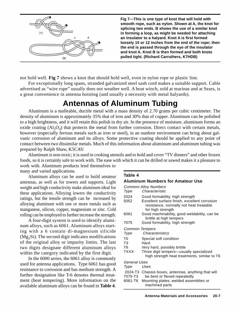
Fig 7—This is one type of knot that will hold withsmooth rope, such as nylon. Shown at A, the knot forsplicing two ends. B shows the use of a similar knotin forming a loop, as might be needed for attachingan insulator to a halyard. Knot A is first formedloosely 10 or 12 inches from the end of the rope; thenthe end is passed through the eye of the insulatorand knot A. Knot B is then formed and both knotspulled tight. (Richard Carruthers, K7HDB)
not hold well. Fig 7 shows a knot that should hold well, even in nylon rope or plastic line.For exceptionally long spans, stranded galvanized steel sash cord makes a suitable support. Cable
advertised as “wire rope” usually does not weather well. A boat winch, sold at marinas and at Sears, isa great convenience in antenna hoisting (and usually a necessity with metal halyards).
Antennas of Aluminum TubingAluminum is a malleable, ductile metal with a mass density of 2.70 grams per cubic centimeter. The
density of aluminum is approximately 35% that of iron and 30% that of copper. Aluminum can be polishedto a high brightness, and it will retain this polish in dry air. In the presence of moisture, aluminum forms anoxide coating (Al2O3) that protects the metal from further corrosion. Direct contact with certain metals,however (especially ferrous metals such as iron or steel), in an outdoor environment can bring about gal-vanic corrosion of aluminum and its alloys. Some protective coating should be applied to any point ofcontact between two dissimilar metals. Much of this information about aluminum and aluminum tubing wasprepared by Ralph Shaw, K5CAV.
Aluminum is non-toxic; it is used in cooking utensils and to hold and cover “TV dinners” and other frozenfoods, so it is certainly safe to work with. The ease with which it can be drilled or sawed makes it a pleasure towork with. Aluminum products lend themselves tomany and varied applications.
Aluminum alloys can be used to build amateurantennas, as well as for towers and supports. Lightweight and high conductivity make aluminum ideal forthese applications. Alloying lowers the conductivityratings, but the tensile strength can be increased byalloying aluminum with one or more metals such asmanganese, silicon, copper, magnesium or zinc. Coldrolling can be employed to further increase the strength.
A four-digit system is used to identify alumi-num alloys, such as 6061. Aluminum alloys start-ing with a 6 contain di-magnesium silicide(Mg2Si). The second digit indicates modificationsof the original alloy or impurity limits. The lasttwo digits designate different aluminum alloyswithin the category indicated by the first digit.
In the 6000 series, the 6061 alloy is commonlyused for antenna applications. Type 6061 has goodresistance to corrosion and has medium strength. Afurther designation like T-6 denotes thermal treat-ment (heat tempering). More information on theavailable aluminum alloys can be found in Table 4.
Table 4Aluminum Numbers for Amateur UseCommon Alloy NumbersType Characteristic2024 Good formability, high strength5052 Excellent surface finish, excellent corrosion
resistance, normally not heat treatablefor high strength
6061 Good machinability, good weldability, can bebrittle at high tempers
7075 Good formability, high strength
Common TempersType CharacteristicsT0 Special soft conditionT3 HardT6 Very hard, possibly brittleTXXX Three digit tempers—usually specialized
high strength heat treatments, similar to T6
General UsesType Uses 2024-T3 Chassis boxes, antennas, anything that will7075-T3 be bent or flexed repeatedly6061-T6 Mounting plates, welded assemblies or
machined parts
20-8 Chapter 20
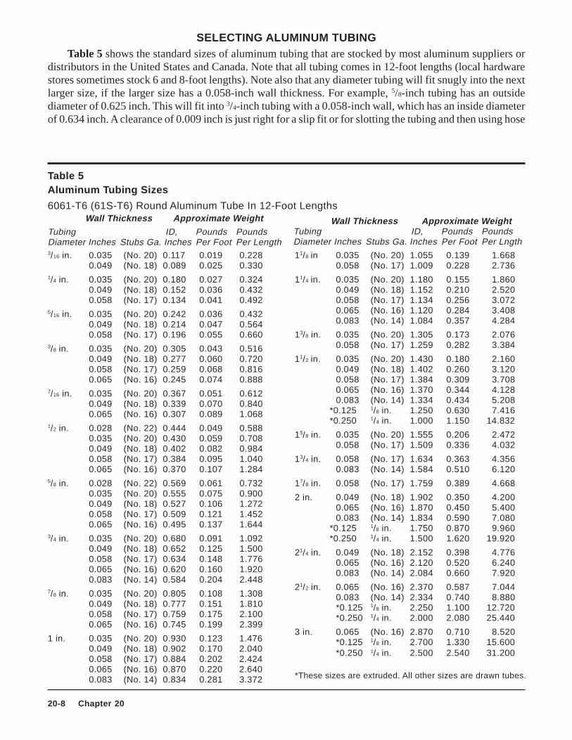
Table 5Aluminum Tubing Sizes
6061-T6 (61S-T6) Round Aluminum Tube In 12-Foot LengthsWall Thickness Approximate Weight
11/8 in 0.035 (No. 20) 1.055 0.139 1.6680.058 (No. 17) 1.009 0.228 2.736
11/4 in. 0.035 (No. 20) 1.180 0.155 1.8600.049 (No. 18) 1.152 0.210 2.5200.058 (No. 17) 1.134 0.256 3.0720.065 (No. 16) 1.120 0.284 3.4080.083 (No. 14) 1.084 0.357 4.284
13/8 in. 0.035 (No. 20) 1.305 0.173 2.0760.058 (No. 17) 1.259 0.282 3.384
11/2 in. 0.035 (No. 20) 1.430 0.180 2.1600.049 (No. 18) 1.402 0.260 3.1200.058 (No. 17) 1.384 0.309 3.7080.065 (No. 16) 1.370 0.344 4.1280.083 (No. 14) 1.334 0.434 5.208
*0.125 1/8 in. 1.250 0.630 7.416 *0.250 1/4 in. 1.000 1.150 14.832
15/8 in. 0.035 (No. 20) 1.555 0.206 2.4720.058 (No. 17) 1.509 0.336 4.032
13/4 in. 0.058 (No. 17) 1.634 0.363 4.3560.083 (No. 14) 1.584 0.510 6.120
17/8 in. 0.058 (No. 17) 1.759 0.389 4.668
2 in. 0.049 (No. 18) 1.902 0.350 4.2000.065 (No. 16) 1.870 0.450 5.4000.083 (No. 14) 1.834 0.590 7.080
*0.125 1/8 in. 1.750 0.870 9.960 *0.250 1/4 in. 1.500 1.620 19.920
21/4 in. 0.049 (No. 18) 2.152 0.398 4.7760.065 (No. 16) 2.120 0.520 6.2400.083 (No. 14) 2.084 0.660 7.920
21/2 in. 0.065 (No. 16) 2.370 0.587 7.0440.083 (No. 14) 2.334 0.740 8.880*0.125 1/8 in. 2.250 1.100 12.720*0.250 1/4 in. 2.000 2.080 25.440
3 in. 0.065 (No. 16) 2.870 0.710 8.520*0.125 1/8 in. 2.700 1.330 15.600*0.250 1/4 in. 2.500 2.540 31.200
*These sizes are extruded. All other sizes are drawn tubes.
Wall Thickness Approximate WeightTubing ID, Pounds PoundsDiameter Inches Stubs Ga. Inches Per Foot Per Lngth
Tubing ID, Pounds PoundsDiameter Inches Stubs Ga. Inches Per Foot Per Length3/16 in. 0.035 (No. 20) 0.117 0.019 0.228
0.049 (No. 18) 0.089 0.025 0.3301/4 in. 0.035 (No. 20) 0.180 0.027 0.324
0.049 (No. 18) 0.152 0.036 0.4320.058 (No. 17) 0.134 0.041 0.492
5/16 in. 0.035 (No. 20) 0.242 0.036 0.4320.049 (No. 18) 0.214 0.047 0.5640.058 (No. 17) 0.196 0.055 0.660
3/8 in. 0.035 (No. 20) 0.305 0.043 0.5160.049 (No. 18) 0.277 0.060 0.7200.058 (No. 17) 0.259 0.068 0.8160.065 (No. 16) 0.245 0.074 0.888
7/16 in. 0.035 (No. 20) 0.367 0.051 0.6120.049 (No. 18) 0.339 0.070 0.8400.065 (No. 16) 0.307 0.089 1.068
1/2 in. 0.028 (No. 22) 0.444 0.049 0.5880.035 (No. 20) 0.430 0.059 0.7080.049 (No. 18) 0.402 0.082 0.9840.058 (No. 17) 0.384 0.095 1.0400.065 (No. 16) 0.370 0.107 1.284
5/8 in. 0.028 (No. 22) 0.569 0.061 0.7320.035 (No. 20) 0.555 0.075 0.9000.049 (No. 18) 0.527 0.106 1.2720.058 (No. 17) 0.509 0.121 1.4520.065 (No. 16) 0.495 0.137 1.644
3/4 in. 0.035 (No. 20) 0.680 0.091 1.0920.049 (No. 18) 0.652 0.125 1.5000.058 (No. 17) 0.634 0.148 1.7760.065 (No. 16) 0.620 0.160 1.9200.083 (No. 14) 0.584 0.204 2.448
7/8 in. 0.035 (No. 20) 0.805 0.108 1.3080.049 (No. 18) 0.777 0.151 1.8100.058 (No. 17) 0.759 0.175 2.1000.065 (No. 16) 0.745 0.199 2.399
1 in. 0.035 (No. 20) 0.930 0.123 1.4760.049 (No. 18) 0.902 0.170 2.0400.058 (No. 17) 0.884 0.202 2.4240.065 (No. 16) 0.870 0.220 2.6400.083 (No. 14) 0.834 0.281 3.372
SELECTING ALUMINUM TUBINGTable 5 shows the standard sizes of aluminum tubing that are stocked by most aluminum suppliers or
distributors in the United States and Canada. Note that all tubing comes in 12-foot lengths (local hardwarestores sometimes stock 6 and 8-foot lengths). Note also that any diameter tubing will fit snugly into the nextlarger size, if the larger size has a 0.058-inch wall thickness. For example, 5/8-inch tubing has an outsidediameter of 0.625 inch. This will fit into 3/4-inch tubing with a 0.058-inch wall, which has an inside diameterof 0.634 inch. A clearance of 0.009 inch is just right for a slip fit or for slotting the tubing and then using hose
Antenna Materials and Accessories 20-9
clamps. Always get the next larger size and specify a 0.058-inch wall to obtain the 0.009-inch clearance.A little figuring with Table 5 will give you all the information you need to build a beam, including
what the antenna will weigh. The 6061-T6 type of aluminum has a relatively high strength and hasgood workability. It is highly resistant to corrosion and will bend without taking a “set.”
SOURCES FOR ALUMINUMAluminum can be purchased new, and suppliers are listed in Chapter 21. But don’t overlook the local
metal scrap yard. The price varies, but between 35 and 60 cents per pound is typical for scrap aluminum.Some aluminum items to look for include aluminum vaulting poles, tent poles, tubing and fittings fromscrapped citizen’s band antennas, and aluminum angle stock. The scrap yard may even have a section or twoof triangular aluminum tower.
Aluminum vaulting poles are 12 or 14 feet long and range in diameter from 11/2 to 13/4 inches.These poles are suitable for the center-element sections of large 14-MHz beams or as booms for smallerantennas. Tent poles range in length from 21/2 to 4 feet. The tent poles are usually tapered; they can besplit on the larger end and then mated with the smaller end of another pole of the same diameter. Asmall stainless-steel hose clamp (sometimes also available at scrap yards!) can be used to fasten thepoles at this junction. A 14 or 21-MHz element can be constructed from several tent poles in thisfashion. If a longer continuous piece of tubing is available, it can be used for the center section todecrease the number of junctions and clamps.
Other aluminum scrap is sometimes available, such as US Army aluminum mast sections desig-nated AB-85/GRA-4 (J&H Smith Mfg). These are 3 foot sections with a 15/8 inch diameter. The endsare swaged so they can be assembled one into another. These are ideal for making a portable mast fora 144-MHz beam or for Field Day applications.
CONSTRUCTION WITH ALUMINUM TUBINGMost antennas built for frequencies of 14 MHz and above are made to be rotated. Constructing a
rotatable antenna requires materials that are strong, lightweight and easy to obtain. The materialsrequired to build a suitable antenna will vary, depending on many factors. Perhaps the most importantfactor that determines the type of hardware needed is the weather conditions normally encountered.High winds usually don’t cause as much damage to an antenna as does ice, especially ice alongwith high winds. Aluminum element and boom sizes should be selected so the various sections oftubing will telescope to provide the necessarytotal length.
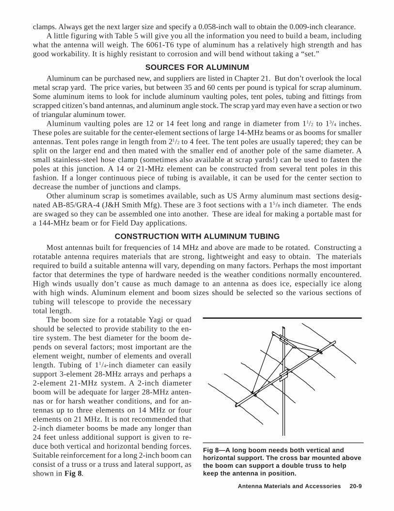
The boom size for a rotatable Yagi or quadshould be selected to provide stability to the en-tire system. The best diameter for the boom de-pends on several factors; most important are theelement weight, number of elements and overalllength. Tubing of 11/4-inch diameter can easilysupport 3-element 28-MHz arrays and perhaps a2-element 21-MHz system. A 2-inch diameterboom will be adequate for larger 28-MHz anten-nas or for harsh weather conditions, and for an-tennas up to three elements on 14 MHz or fourelements on 21 MHz. It is not recommended that2-inch diameter booms be made any longer than24 feet unless additional support is given to re-duce both vertical and horizontal bending forces.Suitable reinforcement for a long 2-inch boom canconsist of a truss or a truss and lateral support, asshown in Fig 8.
Fig 8—A long boom needs both vertical andhorizontal support. The cross bar mounted abovethe boom can support a double truss to helpkeep the antenna in position.
20-10 Chapter 20
A boom length of 24 feet is about the point wherea 3-inch diameter begins to be very worthwhile. Thisdimension provides a considerable improvement inoverall mechanical stability as well as increasedclamping surface area for element hardware. Clamp-ing surface area is extremely important if heavy ic-ing is common and rotation of elements around theboom is to be avoided. Pinning an element to theboom with a large bolt helps in this regard. On smallerdiameter booms, however, the elements sometimeswork loose and tend to elongate the pinning holes inboth the element and the boom. After some time theelements shift their positions slightly (sometimesfrom day to day!) and give a rather ragged appear-ance to the system, even though this doesn’ t gener-ally harm the electrical performance.
A 3-inch diameter boom with a wall thicknessof 0.065 inch is satisfactory for antennas up toabout a 5-element, 14-MHz array that is spacedon a 40-foot long boom. A truss is recommendedfor any boom longer than 24 feet.
There is no RF voltage at the center of a para-sitic element, so no insulation is required in mount-ing elements that are centered on the boom (drivenelements excepted). This is true whether the boomis metal or a nonconducting material. Metal boomshave a small “shortening effect” on elements that runthrough them. With materials sizes commonly em-ployed, this is not more than 1% of the element length,and may not be noticeable in many applications. It isjust perceptible with 1/2-inch tubing booms used on432 MHz, for example. Design-formula lengths canbe used as given, if the matching is adjusted in thefrequency range one expects to use. The center fre-quency of an all-metal array will tend to be 0.5 to 1% higher than a similar system built of wooden support-ing members.
Element AssemblyWhile the maximum safe length of an antenna element depends to some extent on its diameter, the
only laws that specify the minimum diameter of an element are the laws of nature. That is, the elementmust be rugged enough to survive whatever weather conditions it will encounter.
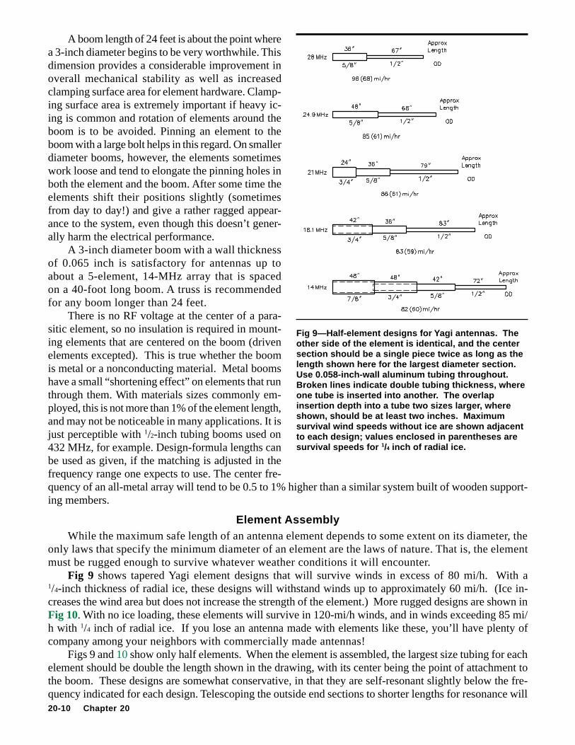
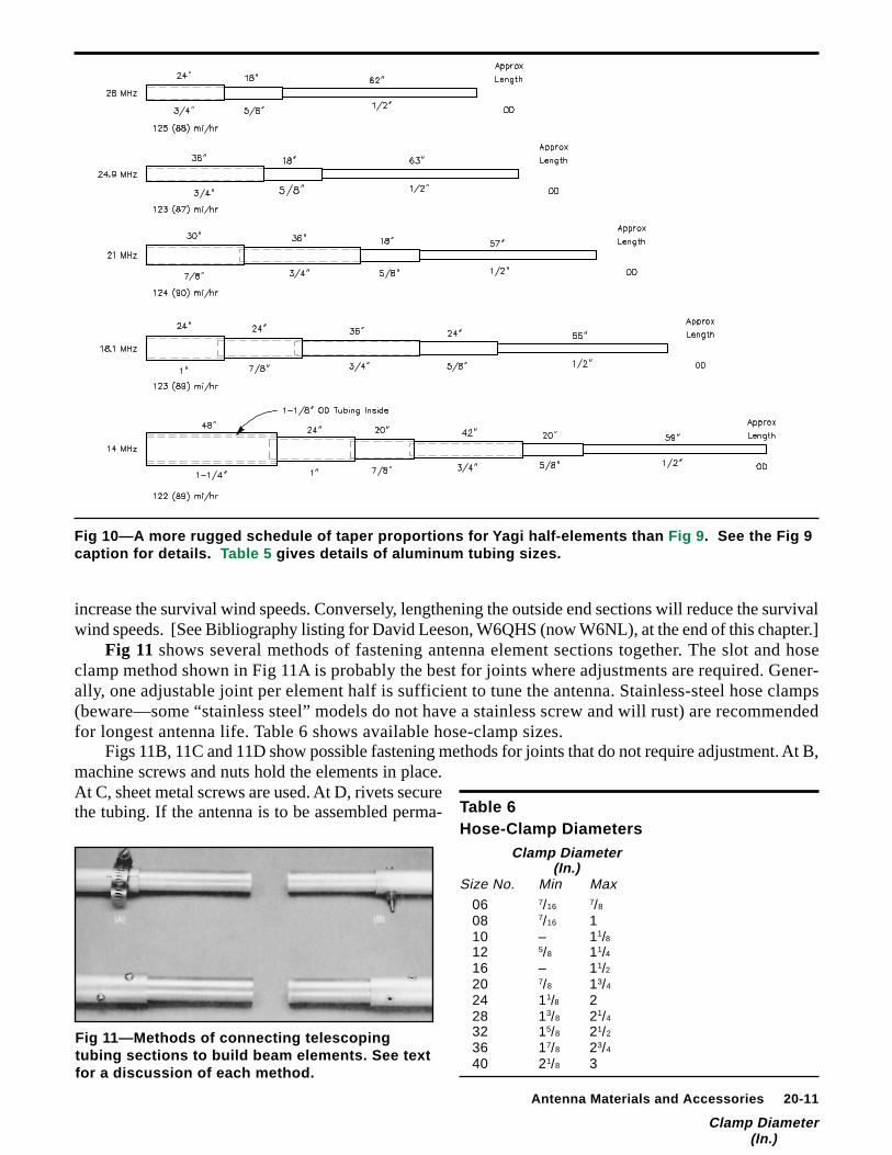
Fig 9 shows tapered Yagi element designs that will survive winds in excess of 80 mi/h. With a1/4-inch thickness of radial ice, these designs will withstand winds up to approximately 60 mi/h. (Ice in-creases the wind area but does not increase the strength of the element.) More rugged designs are shown inFig 10. With no ice loading, these elements will survive in 120-mi/h winds, and in winds exceeding 85 mi/h with 1/4 inch of radial ice. If you lose an antenna made with elements like these, you’ll have plenty ofcompany among your neighbors with commercially made antennas!
Figs 9 and 10 show only half elements. When the element is assembled, the largest size tubing for eachelement should be double the length shown in the drawing, with its center being the point of attachment tothe boom. These designs are somewhat conservative, in that they are self-resonant slightly below the fre-quency indicated for each design. Telescoping the outside end sections to shorter lengths for resonance will
Fig 9—Half-element designs fo r Yagi antennas. Theother side of the element is identical, and the centersection should be a single piece twice as long as thelength shown here for the largest diameter section.Use 0.058-inch-wall aluminum tubing throughout.Broken lines indicate double tubing thickness, whereone tube is inserted into anothe r. The overlapinsertion depth into a tube two sizes large r, whereshown, should be at least two inches. Maximumsurvival wind speeds without ice are shown adjacentto each design; values enclosed in parentheses aresurvival speeds for 1/4 inch of radial ice.
Antenna Materials and Accessories 20-11
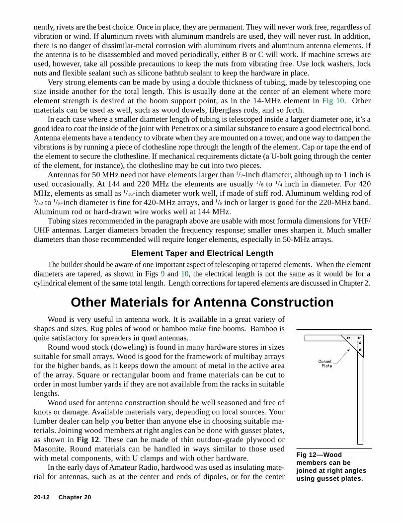
Fig 11—Methods of connecting telescopingtubing sections to build beam elements. See textfor a discussion of each method.
Fig 10—A more rugged schedule of taper proportions fo r Yagi half-elements than Fig 9 . See the Fig 9caption for details. Table 5 gives details of aluminum tubing sizes.
Table 6Hose-Clamp Diameters
Clamp Diameter(In.)
Size No. Min Max 06 7/16 7/8
08 7/16 1 10 – 11/8 12 5/8 11/4 16 – 11/2 20 7/8 13/4
24 11/8 2 28 13/8 21/4
32 15/8 21/2
36 17/8 23/4
40 21/8 3
increase the survival wind speeds. Conversely, lengthening the outside end sections will reduce the survivalwind speeds. [See Bibliography listing for David Leeson, W6QHS (now W6NL), at the end of this chapter.]
Fig 11 shows several methods of fastening antenna element sections together. The slot and hoseclamp method shown in Fig 11A is probably the best for joints where adjustments are required. Gener-ally, one adjustable joint per element half is sufficient to tune the antenna. Stainless-steel hose clamps(beware—some “stainless steel” models do not have a stainless screw and will rust) are recommendedfor longest antenna life. Table 6 shows available hose-clamp sizes.
Figs 11B, 11C and 11D show possible fastening methods for joints that do not require adjustment. At B,machine screws and nuts hold the elements in place.At C, sheet metal screws are used. At D, rivets securethe tubing. If the antenna is to be assembled perma-
Clamp Diameter(In.)
20-12 Chapter 20
nently, rivets are the best choice. Once in place, they are permanent. They will never work free, regardless ofvibration or wind. If aluminum rivets with aluminum mandrels are used, they will never rust. In addition,there is no danger of dissimilar-metal corrosion with aluminum rivets and aluminum antenna elements. Ifthe antenna is to be disassembled and moved periodically, either B or C will work. If machine screws areused, however, take all possible precautions to keep the nuts from vibrating free. Use lock washers, locknuts and flexible sealant such as silicone bathtub sealant to keep the hardware in place.
Very strong elements can be made by using a double thickness of tubing, made by telescoping onesize inside another for the total length. This is usually done at the center of an element where moreelement strength is desired at the boom support point, as in the 14-MHz element in Fig 10. Othermaterials can be used as well, such as wood dowels, fiberglass rods, and so forth.
In each case where a smaller diameter length of tubing is telescoped inside a larger diameter one, it’s agood idea to coat the inside of the joint with Penetrox or a similar substance to ensure a good electrical bond.Antenna elements have a tendency to vibrate when they are mounted on a tower, and one way to dampen thevibrations is by running a piece of clothesline rope through the length of the element. Cap or tape the end ofthe element to secure the clothesline. If mechanical requirements dictate (a U-bolt going through the centerof the element, for instance), the clothesline may be cut into two pieces.
Antennas for 50 MHz need not have elements larger than 1/2-inch diameter, although up to 1 inch isused occasionally. At 144 and 220 MHz the elements are usually 1/8 to 1/4 inch in diameter. For 420MHz, elements as small as 1/16-inch diameter work well, if made of stiff rod. Aluminum welding rod of3/32 to 1/8-inch diameter is fine for 420-MHz arrays, and 1/8 inch or larger is good for the 220-MHz band.Aluminum rod or hard-drawn wire works well at 144 MHz.
Tubing sizes recommended in the paragraph above are usable with most formula dimensions for VHF/UHF antennas. Larger diameters broaden the frequency response; smaller ones sharpen it. Much smallerdiameters than those recommended will require longer elements, especially in 50-MHz arrays.
Element Taper and Electrical LengthThe builder should be aware of one important aspect of telescoping or tapered elements. When the element
diameters are tapered, as shown in Figs 9 and 10, the electrical length is not the same as it would be for acylindrical element of the same total length. Length corrections for tapered elements are discussed in Chapter 2.
Other Materials fo r Antenna ConstructionWood is very useful in antenna work. It is available in a great variety of
shapes and sizes. Rug poles of wood or bamboo make fine booms. Bamboo isquite satisfactory for spreaders in quad antennas.
Round wood stock (doweling) is found in many hardware stores in sizessuitable for small arrays. Wood is good for the framework of multibay arraysfor the higher bands, as it keeps down the amount of metal in the active areaof the array. Square or rectangular boom and frame materials can be cut toorder in most lumber yards if they are not available from the racks in suitablelengths.
Wood used for antenna construction should be well seasoned and free ofknots or damage. Available materials vary, depending on local sources. Yourlumber dealer can help you better than anyone else in choosing suitable ma-terials. Joining wood members at right angles can be done with gusset plates,as shown in Fig 12. These can be made of thin outdoor-grade plywood orMasonite. Round materials can be handled in ways similar to those usedwith metal components, with U clamps and with other hardware.
In the early days of Amateur Radio, hardwood was used as insulating mate-rial for antennas, such as at the center and ends of dipoles, or for the center
Fig 12—Woodmembers can bejoined at right anglesusing gusset plates.
Antenna Materials and Accessories 20-13
Fig 13—Plastic plumbing parts can be used asantenna center and end insulators.
Fig 14—A mobile-antenna loading coil wound ona polystyrene rod.
insulator of a driven element made of tubing. Wooddowels cut to length were the most common source.To drive out moisture and prevent the subsequentabsorption of moisture into the wood, it was treatedbefore use by boiling it in paraffin. Of course today’stechnology has produced superior materials for in-sulators in terms of both strength and insulating quali-ties. However, the technique is worth considerationin an emergency situation or if low cost is a primerequirement. “Baking” the wood in an oven for ashort period at 200°F should drive out any moisture.Then treatment as described in the next paragraphshould prevent moisture absorption. The use of woodinsulators should be avoided at high-voltage pointsif high power is being used.
All wood used in outdoor installations shouldbe protected from the weather with varnish or paint.A good grade of marine spar varnish or polyurethanevarnish will offer protection for years in mild cli-mates, and one or more seasons in harsh climates.Epoxy-based paints also offer good protection.
PlasticsPlastic tubing and rods of various sizes are
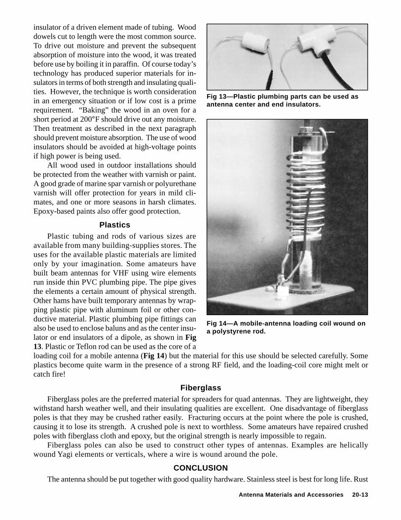
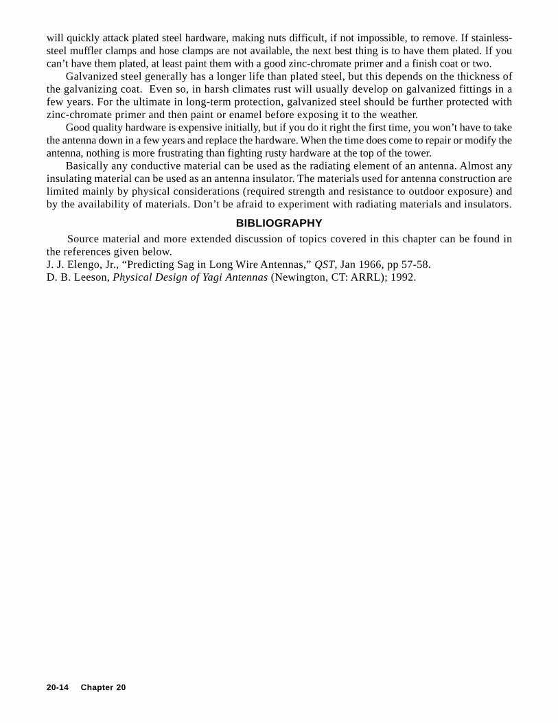
available from many building-supplies stores. Theuses for the available plastic materials are limitedonly by your imagination. Some amateurs havebuilt beam antennas for VHF using wire elementsrun inside thin PVC plumbing pipe. The pipe givesthe elements a certain amount of physical strength.Other hams have built temporary antennas by wrap-ping plastic pipe with aluminum foil or other con-ductive material. Plastic plumbing pipe fittings canalso be used to enclose baluns and as the center insu-lator or end insulators of a dipole, as shown in Fig13. Plastic or Teflon rod can be used as the core of aloading coil for a mobile antenna (Fig 14) but the material for this use should be selected carefully. Someplastics become quite warm in the presence of a strong RF field, and the loading-coil core might melt orcatch fire!
FiberglassFiberglass poles are the preferred material for spreaders for quad antennas. They are lightweight, they
withstand harsh weather well, and their insulating qualities are excellent. One disadvantage of fiberglasspoles is that they may be crushed rather easily. Fracturing occurs at the point where the pole is crushed,causing it to lose its strength. A crushed pole is next to worthless. Some amateurs have repaired crushedpoles with fiberglass cloth and epoxy, but the original strength is nearly impossible to regain.
Fiberglass poles can also be used to construct other types of antennas. Examples are helicallywound Yagi elements or verticals, where a wire is wound around the pole.
CONCLUSIONThe antenna should be put together with good quality hardware. Stainless steel is best for long life. Rust
20-14 Chapter 20
will quickly attack plated steel hardware, making nuts difficult, if not impossible, to remove. If stainless-steel muffler clamps and hose clamps are not available, the next best thing is to have them plated. If youcan’t have them plated, at least paint them with a good zinc-chromate primer and a finish coat or two.
Galvanized steel generally has a longer life than plated steel, but this depends on the thickness ofthe galvanizing coat. Even so, in harsh climates rust will usually develop on galvanized fittings in afew years. For the ultimate in long-term protection, galvanized steel should be further protected withzinc-chromate primer and then paint or enamel before exposing it to the weather.
Good quality hardware is expensive initially, but if you do it right the first time, you won’t have to takethe antenna down in a few years and replace the hardware. When the time does come to repair or modify theantenna, nothing is more frustrating than fighting rusty hardware at the top of the tower.
Basically any conductive material can be used as the radiating element of an antenna. Almost anyinsulating material can be used as an antenna insulator. The materials used for antenna construction arelimited mainly by physical considerations (required strength and resistance to outdoor exposure) andby the availability of materials. Don’t be afraid to experiment with radiating materials and insulators.
BIBLIOGRAPHY Source material and more extended discussion of topics covered in this chapter can be found inthe references given below.J. J. Elengo, Jr., “Predicting Sag in Long Wire Antennas,” QST, Jan 1966, pp 57-58.D. B. Leeson, Physical Design of Yagi Antennas (Newington, CT: ARRL); 1992.


![TETRA Accessories - funkwerk-sc.com€¦ · TETRA Accessories Accessories for the funktel FT4 TETRA handset series. Antenna a FT4 [1] 380-400 MHz, helical (Colour code: yellow) 5.900.102.838](https://img.pdfslide.us/doc/110x75/5b3a9ab87f8b9a213f8b8f3b/tetra-accessories-funkwerk-sc-tetra-accessories-accessories-for-the-funktel.jpg)