Embed Size (px)
Citation preview
WS800 Wireless Microphone System
Antenna Application Guide
Application Guide
2
ClearOne’s digital technology supports much larger microphone systems than is possible with analog technology. It should be noted that marginal antenna designs may work well with smaller systems, but they can cause hits and dropout as the channel counts go up. On the other hand, a well designed antenna system delivers excellent performance with both big and small systems.
See Pg. 12 for ClearOne’s Free Antenna Design Service Offer.
ClearOne engineers rely on following these design criteria:
Design Goal: Keep the power level of all the microphones between -40 and -60 dBm all of the time to prevent hits and dropouts.
Design Rules: + Rule 1: Equal Distance
(1)
The distance to the most distant transmitter should not be more than double the distance to the closest transmitter. This ensures that all transmitters have relatively equal signal strength at the receiver’s antenna. Having some transmitters closer than others adjusts the receiver’s sensitivity to the close by transmitter’s signal which then desensitizes the receiver to the farther away transmitters, which exaggerates the relative weakness of the farther away transmitters compared to the nearer ones.
If Intermodulation Distortion (IMD) is present (see the appendix below), the IMD signals may shadow the assigned frequency of some of the transmitters. This adds to the importance of keeping all of the transmitters an equal distance to the receiver antenna.
When transmitters are too close to the receiver antennas or they are set at a greater transmitter RF power setting than needed, this can be a cause of IMD.
+ Rule 2: Diversity(2)
The antennas should be separated so that the ends of the transmitter antenna (the null; see appendix
Pg. 7) cannot be aimed at both antennas at the same time. There are also weak and strong spots in the reception pattern of the room for each antenna that are evened out by having two antennas in two
physical positions.
+ Rule 3: Line of Sight All wireless microphones exchange the greatest energy transfer in a direct line-of-sight between the
transmitter antenna and the receiver antenna. All transmitters should be in the line-of-sight of both antennas. Line-of-sight means the transmitters are not blocked by metal, concrete, or similar
radio opaque objects, and there is minimal signal absorption through people’s bodies. Blocking line-of- sight to the antennas may not cause immediate drop outs, however the transmitter becomes less resistant to drop outs caused by the system not conforming to the other design rules.
+ Rule 4: Cable Loss The total antenna cable loss should be less than -15 dB at 900 MHz. This is controlled by using the
recommended cable type for the recommended distance.
+ Rule 5: Range Loss Doubling the distance between a transmitter and an antenna cuts the signal strength by a factor of 4
(inverse square law). Keep the antennas as close to the area where the transmitters will be used as practical without violating Rule 1.
+ Rule 6: Transmitter Power(5)
Adjust the transmitter power to meet the -40 to -60 dBm reading as seen in the ClearOne Wireless Graphic User Interface scan function.
ClearOne Extension Antenna Application Guide
3
Factor Antennas on Ceiling
EqualDistance
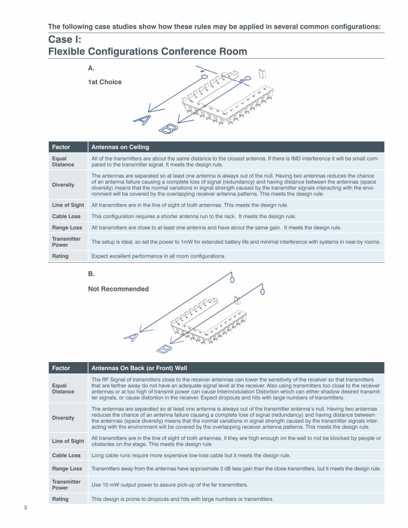
All of the transmitters are about the same distance to the closest antenna. If there is IMD interference it will be small com-pared to the transmitter signal. It meets the design rule.
Diversity
The antennas are separated so at least one antenna is always out of the null. Having two antennas reduces the chance of an antenna failure causing a complete loss of signal (redundancy) and having distance between the antennas (space diversity) means that the normal variations in signal strength caused by the transmitter signals interacting with the envi-ronment will be covered by the overlapping receiver antenna patterns. This meets the design rule.
Line of Sight All transmitters are in the line of sight of both antennas. This meets the design rule.
Cable Loss This configuration requires a shorter antenna run to the rack. It meets the design rule.
Range Loss All transmitters are close to at least one antenna and have about the same gain. It meets the design rule.
TransmitterPower The setup is ideal, so set the power to 1mW for extended battery life and minimal interference with systems in near-by rooms.
Rating Expect excellent performance in all room configurations.
Factor Antennas On Back (or Front) Wall
EqualDistance
The RF Signal of transmitters close to the receiver antennas can lower the sensitivity of the receiver so that transmitters that are farther away do not have an adequate signal level at the receiver. Also using transmitters too close to the receiver antennas or at too high of transmit power can cause Intermodulation Distortion which can either shadow desired transmit-ter signals, or cause distortion in the receiver. Expect dropouts and hits with large numbers of transmitters.
Diversity
The antennas are separated so at least one antenna is always out of the transmitter antenna’s null. Having two antennas reduces the chance of an antenna failure causing a complete loss of signal (redundancy) and having distance between the antennas (space diversity) means that the normal variations in signal strength caused by the transmitter signals inter-acting with the environment will be covered by the overlapping receiver antenna patterns. This meets the design rule.
Line of Sight All transmitters are in the line of sight of both antennas, if they are high enough on the wall to not be blocked by people or obstacles on the stage. This meets the design rule
Cable Loss Long cable runs require more expensive low-loss cable but it meets the design rule.
Range Loss Transmitters away from the antennas have approximate 3 dB less gain than the close transmitters, but it meets the design rule.
TransmitterPower Use 10 mW output power to assure pick-up of the far transmitters.
Rating This design is prone to dropouts and hits with large numbers or transmitters.
A.
B.
1st Choice
Not Recommended
Case I:Flexible Configurations Conference Room
The following case studies show how these rules may be applied in several common configurations:
4
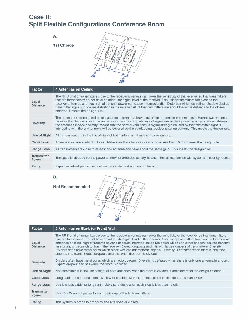
Case II:Split Flexible Configurations Conference Room
Factor 4 Antennas on Ceiling
EqualDistance
The RF Signal of transmitters close to the receiver antennas can lower the sensitivity of the receiver so that transmitters that are farther away do not have an adequate signal level at the receiver. Also using transmitters too close to the receiver antennas or at too high of transmit power can cause Intermodulation Distortion which can either shadow desired transmitter signals, or cause distortion in the receiver. All of the transmitters are about the same distance to the closest antenna. It meets the design rule.
Diversity
The antennas are separated so at least one antenna is always out of the transmitter antenna’s null. Having two antennas reduces the chance of an antenna failure causing a complete loss of signal (redundancy) and having distance between the antennas (space diversity) means that the normal variations in signal strength caused by the transmitter signals interacting with the environment will be covered by the overlapping receiver antenna patterns. This meets the design rule.
Line of Sight All transmitters are in the line of sight of both antennas. It meets the design rule.
Cable Loss Antenna combiners add 3 dB loss. Make sure the total loss in each run is less than 15 dB to meet the design rule.
Range Loss All transmitters are close to at least one antenna and have about the same gain. This meets the design rule.
TransmitterPower The setup is ideal, so set the power to 1mW for extended battery life and minimal interference with systems in near-by rooms.
Rating Expect excellent performance when the divider wall is open or closed.
Factor 2 Antennas on Back (or Front) Wall
EqualDistance
The RF Signal of transmitters close to the receiver antennas can lower the sensitivity of the receiver so that transmitters that are farther away do not have an adequate signal level at the receiver. Also using transmitters too close to the receiver antennas or at too high of transmit power can cause Intermodulation Distortion which can either shadow desired transmit-ter signals, or cause distortion in the receiver. Expect dropouts and hits with large numbers of transmitters. Diversity Dividers often have metal cores which block wireless microphone signals. Diversity is defeated when there is only one antenna in a room. Expect dropouts and hits when the room is divided.
Diversity Dividers often have metal cores which are radio opaque. Diversity is defeated when there is only one antenna in a room. Expect dropout and hits when the room is divided.
Line of Sight No transmitter is in the line of sight of both antennas when the room is divided. It does not meet the design criterion.
Cable Loss Long cable runs require expensive low-loss cable. Make sure the loss on each side is less than 15 dB.
Range Loss Use low-loss cable for long runs. Make sure the loss on each side is less than 15 dB.
TransmitterPower
Use 10 mW output power to assure pick-up of the far transmitters.
Rating This system is prone to dropouts and hits open or closed.
1st Choice
B.
Not Recommended
A.
5
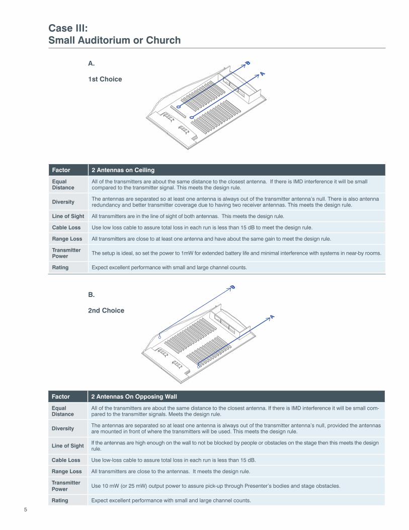
Case III:Small Auditorium or Church
Factor 2 Antennas on Ceiling
EqualDistance
All of the transmitters are about the same distance to the closest antenna. If there is IMD interference it will be small compared to the transmitter signal. This meets the design rule.
Diversity The antennas are separated so at least one antenna is always out of the transmitter antenna’s null. There is also antenna redundancy and better transmitter coverage due to having two receiver antennas. This meets the design rule.
Line of Sight All transmitters are in the line of sight of both antennas. This meets the design rule.
Cable Loss Use low loss cable to assure total loss in each run is less than 15 dB to meet the design rule.
Range Loss All transmitters are close to at least one antenna and have about the same gain to meet the design rule.
TransmitterPower The setup is ideal, so set the power to 1mW for extended battery life and minimal interference with systems in near-by rooms.
Rating Expect excellent performance with small and large channel counts.
Factor 2 Antennas On Opposing Wall
EqualDistance
All of the transmitters are about the same distance to the closest antenna. If there is IMD interference it will be small com-pared to the transmitter signals. Meets the design rule.
Diversity The antennas are separated so at least one antenna is always out of the transmitter antenna’s null, provided the antennas are mounted in front of where the transmitters will be used. This meets the design rule.
Line of Sight If the antennas are high enough on the wall to not be blocked by people or obstacles on the stage then this meets the design rule.
Cable Loss Use low-loss cable to assure total loss in each run is less than 15 dB.
Range Loss All transmitters are close to the antennas. It meets the design rule.
TransmitterPower
Use 10 mW (or 25 mW) output power to assure pick-up through Presenter’s bodies and stage obstacles.
Rating Expect excellent performance with small and large channel counts.
1st Choice
B.
2nd Choice
A.
6
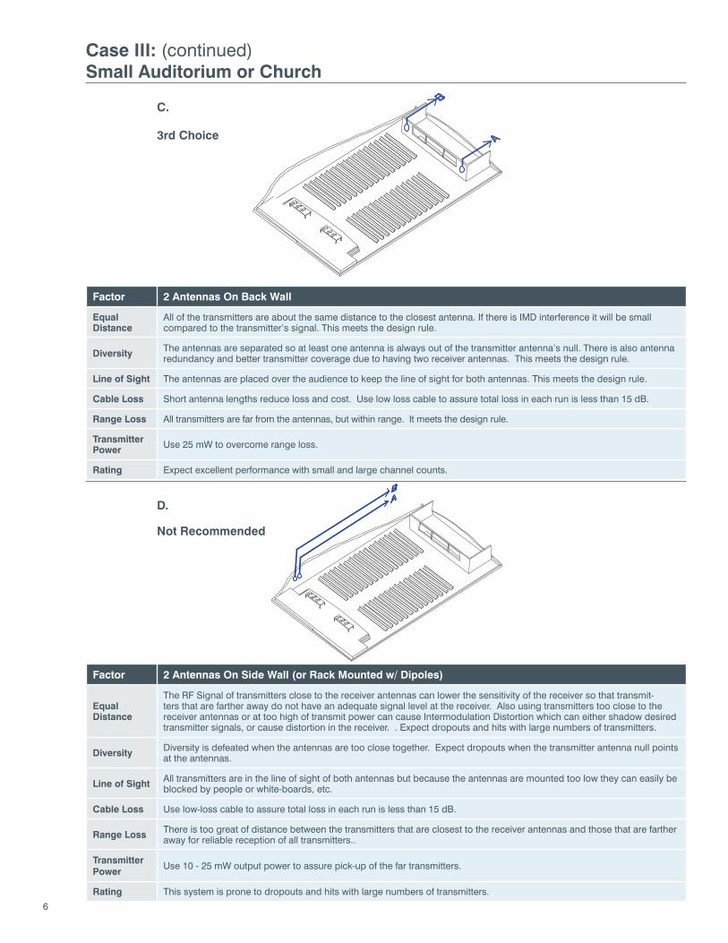
Case III: (continued)Small Auditorium or Church
Factor 2 Antennas On Back Wall
EqualDistance
All of the transmitters are about the same distance to the closest antenna. If there is IMD interference it will be small compared to the transmitter’s signal. This meets the design rule.
Diversity The antennas are separated so at least one antenna is always out of the transmitter antenna’s null. There is also antenna redundancy and better transmitter coverage due to having two receiver antennas. This meets the design rule.
Line of Sight The antennas are placed over the audience to keep the line of sight for both antennas. This meets the design rule.
Cable Loss Short antenna lengths reduce loss and cost. Use low loss cable to assure total loss in each run is less than 15 dB.
Range Loss All transmitters are far from the antennas, but within range. It meets the design rule.
TransmitterPower Use 25 mW to overcome range loss.
Rating Expect excellent performance with small and large channel counts.
Factor 2 Antennas On Side Wall (or Rack Mounted w/ Dipoles)
EqualDistance
The RF Signal of transmitters close to the receiver antennas can lower the sensitivity of the receiver so that transmit-ters that are farther away do not have an adequate signal level at the receiver. Also using transmitters too close to the receiver antennas or at too high of transmit power can cause Intermodulation Distortion which can either shadow desired transmitter signals, or cause distortion in the receiver. . Expect dropouts and hits with large numbers of transmitters.
Diversity Diversity is defeated when the antennas are too close together. Expect dropouts when the transmitter antenna null points at the antennas.
Line of Sight All transmitters are in the line of sight of both antennas but because the antennas are mounted too low they can easily be blocked by people or white-boards, etc.
Cable Loss Use low-loss cable to assure total loss in each run is less than 15 dB.
Range Loss There is too great of distance between the transmitters that are closest to the receiver antennas and those that are farther away for reliable reception of all transmitters..
TransmitterPower
Use 10 - 25 mW output power to assure pick-up of the far transmitters.
Rating This system is prone to dropouts and hits with large numbers of transmitters.
3rd Choice
D.
Not Recommended
C.
7
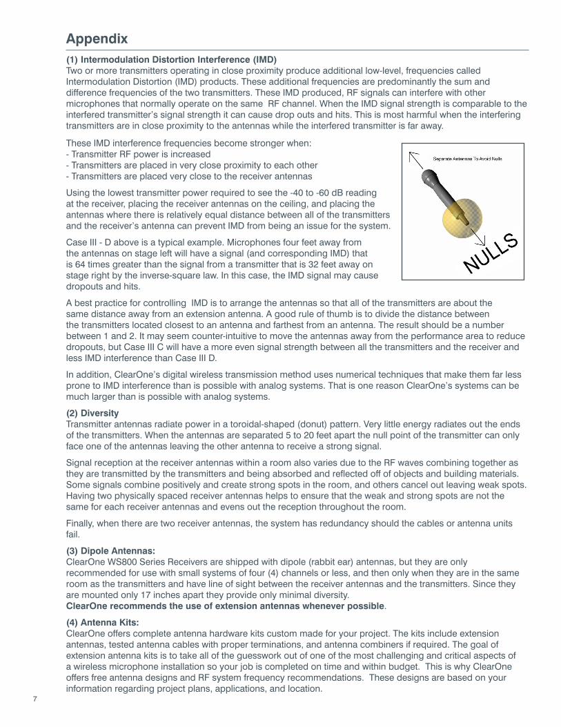
Appendix(1) Intermodulation Distortion Interference (IMD)Two or more transmitters operating in close proximity produce additional low-level, frequencies called Intermodulation Distortion (IMD) products. These additional frequencies are predominantly the sum and difference frequencies of the two transmitters. These IMD produced, RF signals can interfere with other microphones that normally operate on the same RF channel. When the IMD signal strength is comparable to the interfered transmitter’s signal strength it can cause drop outs and hits. This is most harmful when the interfering transmitters are in close proximity to the antennas while the interfered transmitter is far away.
These IMD interference frequencies become stronger when:- Transmitter RF power is increased- Transmitters are placed in very close proximity to each other- Transmitters are placed very close to the receiver antennas
Using the lowest transmitter power required to see the -40 to -60 dB reading at the receiver, placing the receiver antennas on the ceiling, and placing the antennas where there is relatively equal distance between all of the transmitters and the receiver’s antenna can prevent IMD from being an issue for the system.
Case III - D above is a typical example. Microphones four feet away from the antennas on stage left will have a signal (and corresponding IMD) that is 64 times greater than the signal from a transmitter that is 32 feet away on stage right by the inverse-square law. In this case, the IMD signal may cause dropouts and hits.
A best practice for controlling IMD is to arrange the antennas so that all of the transmitters are about the same distance away from an extension antenna. A good rule of thumb is to divide the distance between the transmitters located closest to an antenna and farthest from an antenna. The result should be a number between 1 and 2. It may seem counter-intuitive to move the antennas away from the performance area to reduce dropouts, but Case III C will have a more even signal strength between all the transmitters and the receiver and less IMD interference than Case III D.
In addition, ClearOne’s digital wireless transmission method uses numerical techniques that make them far less prone to IMD interference than is possible with analog systems. That is one reason ClearOne’s systems can be much larger than is possible with analog systems.
(2) DiversityTransmitter antennas radiate power in a toroidal-shaped (donut) pattern. Very little energy radiates out the ends of the transmitters. When the antennas are separated 5 to 20 feet apart the null point of the transmitter can only face one of the antennas leaving the other antenna to receive a strong signal.
Signal reception at the receiver antennas within a room also varies due to the RF waves combining together as they are transmitted by the transmitters and being absorbed and reflected off of objects and building materials. Some signals combine positively and create strong spots in the room, and others cancel out leaving weak spots. Having two physically spaced receiver antennas helps to ensure that the weak and strong spots are not the same for each receiver antennas and evens out the reception throughout the room.
Finally, when there are two receiver antennas, the system has redundancy should the cables or antenna units fail.
(3) Dipole Antennas:ClearOne WS800 Series Receivers are shipped with dipole (rabbit ear) antennas, but they are only recommended for use with small systems of four (4) channels or less, and then only when they are in the same room as the transmitters and have line of sight between the receiver antennas and the transmitters. Since they are mounted only 17 inches apart they provide only minimal diversity. ClearOne recommends the use of extension antennas whenever possible.
(4) Antenna Kits:ClearOne offers complete antenna hardware kits custom made for your project. The kits include extension antennas, tested antenna cables with proper terminations, and antenna combiners if required. The goal of extension antenna kits is to take all of the guesswork out of one of the most challenging and critical aspects of a wireless microphone installation so your job is completed on time and within budget. This is why ClearOne offers free antenna designs and RF system frequency recommendations. These designs are based on your information regarding project plans, applications, and location.
8
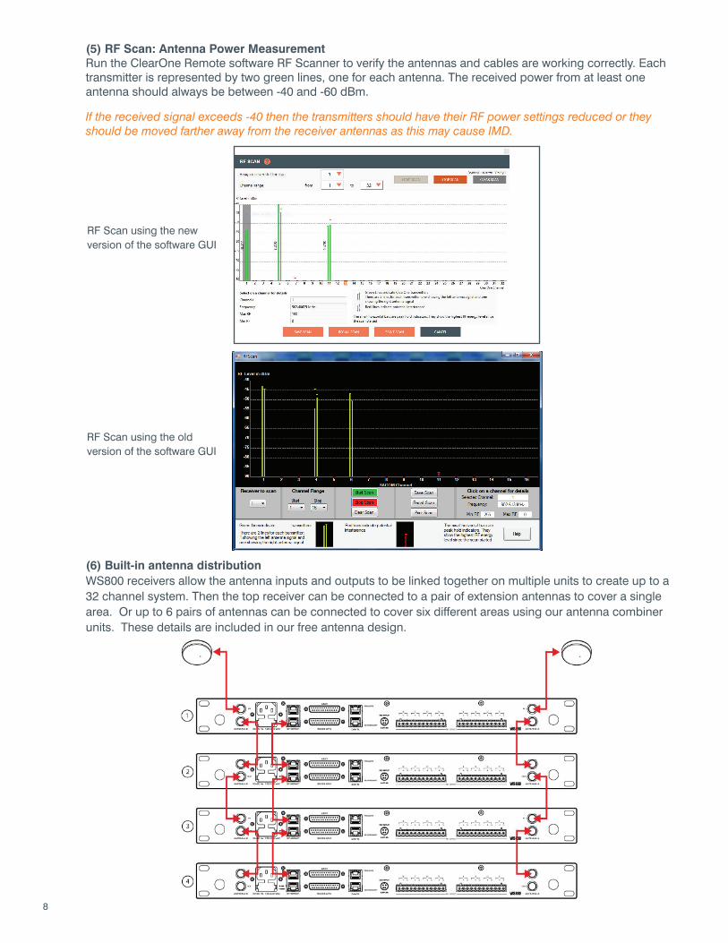
(5) RF Scan: Antenna Power MeasurementRun the ClearOne Remote software RF Scanner to verify the antennas and cables are working correctly. Each transmitter is represented by two green lines, one for each antenna. The received power from at least one antenna should always be between -40 and -60 dBm.
If the received signal exceeds -40 then the transmitters should have their RF power settings reduced or they should be moved farther away from the receiver antennas as this may cause IMD.
(6) Built-in antenna distributionWS800 receivers allow the antenna inputs and outputs to be linked together on multiple units to create up to a 32 channel system. Then the top receiver can be connected to a pair of extension antennas to cover a single area. Or up to 6 pairs of antennas can be connected to cover six different areas using our antenna combiner units. These details are included in our free antenna design.
RF Scan using the new version of the software GUI
RF Scan using the old version of the software GUI
9
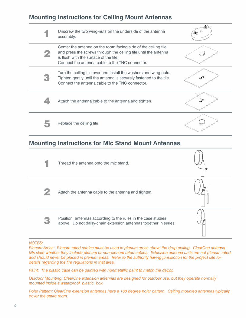
Mounting Instructions for Ceiling Mount Antennas
Mounting Instructions for Mic Stand Mount Antennas
Attach the antenna cable to the antenna and tighten.
Replace the ceiling tile
NOTES:Plenum Areas: Plenum-rated cables must be used in plenum areas above the drop ceiling. ClearOne antenna kits state whether they include plenum or non-plenum rated cables. Extension antenna units are not plenum rated and should never be placed in plenum areas. Refer to the authority having jurisdiction for the project site for details regarding the fire regulations in that area.
Paint: The plastic case can be painted with nonmetallic paint to match the decor.
Outdoor Mounting: ClearOne extension antennas are designed for outdoor use, but they operate normally mounted inside a waterproof plastic box.
Polar Pattern: ClearOne extension antennas have a 160 degree polar pattern. Ceiling mounted antennas typically cover the entire room.
1
2
3
4
5
Unscrew the two wing-nuts on the underside of the antenna assembly.
Center the antenna on the room-facing side of the ceiling tile and press the screws through the ceiling tile until the antenna is flush with the surface of the tile.Connect the antenna cable to the TNC connector.
Turn the ceiling tile over and install the washers and wing-nuts. Tighten gently until the antenna is securely fastened to the tile.Connect the antenna cable to the TNC connector.
Position antennas according to the rules in the case studies above. Do not daisy-chain extension antennas together in series.
1
2
3
Thread the antenna onto the mic stand.
Attach the antenna cable to the antenna and tighten.
10
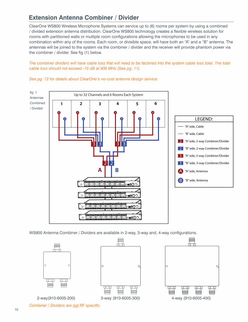
Extension Antenna Combiner / DividerClearOne WS800 Wireless Microphone Systems can service up to (6) rooms per system by using a combined / divided extension antenna distribution. ClearOne WS800 technology creates a flexible wireless solution for rooms with partitioned walls or multiple room configurations allowing the microphones to be used in any combination within any of the rooms. Each room, or divisible space, will have both an “A” and a “B” antenna. The antennas will be joined to the system via the combiner / divider and the receiver will provide phantom power via the combiner / divider. See fig (1) below.
The combiner dividers will have cable loss that will need to be factored into the system cable loss total. The total cable loss should not exceed -15 dB at 900 MHz (See pg. 11).
See pg. 12 for details about ClearOne’s no-cost antenna design service.
WS800 Antenna Combiner / Dividers are available in 2-way, 3-way and, 4-way configurations.
2
3
2
3 33
Up to 32 Channels and 6 Rooms Each System
A B
1 2 3 4 5 6
A A A A A A
B B B B B B
2-way(910-6005-200) 3-way (910-6005-300) 4-way (910-6005-400)
fig. 1
Antennas
Combined
/ Divided
Combiner / Dividers are not RF specific.
2
2
3
3
LEGEND:
A
B
“A” side, 2-way Combiner/Divider
“B” side, 2-way Combiner/Divider
“A” side, 3-way Combiner/Divider
“B” side, 3-way Combiner/Divider
“A” side, Antenna
“B” side, Antenna
“A” side, Cable
“B” side, Cable
11
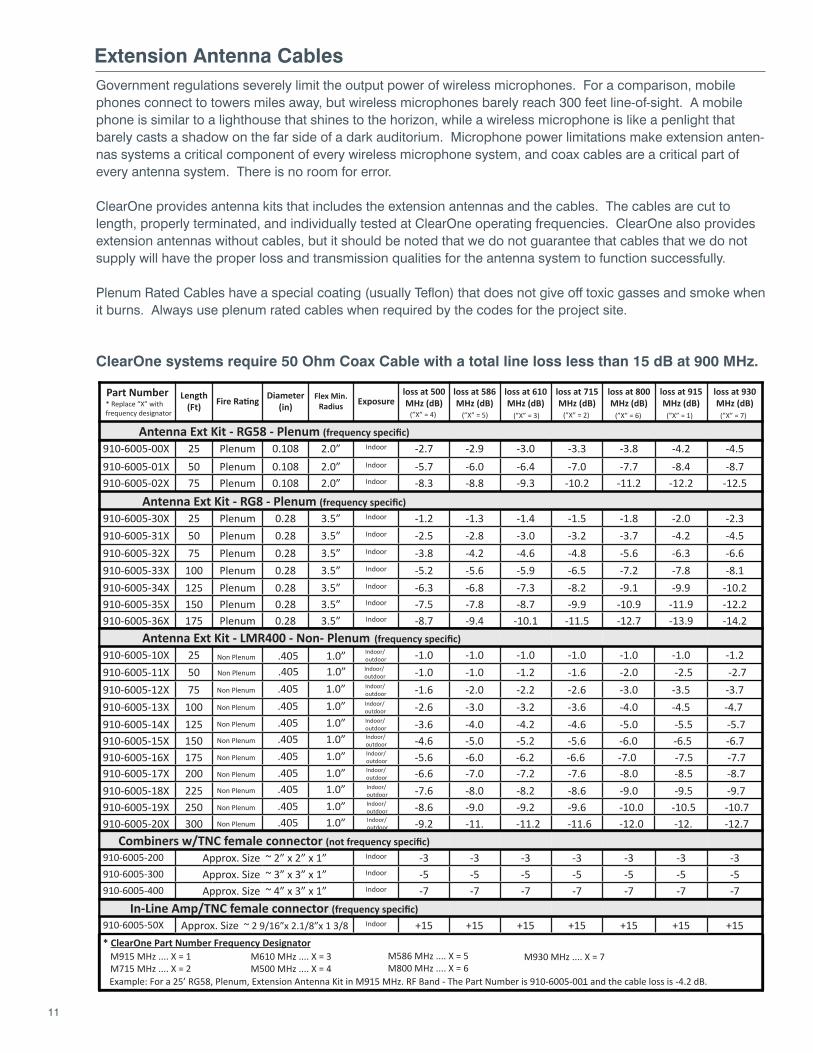
Extension Antenna CablesGovernment regulations severely limit the output power of wireless microphones. For a comparison, mobile phones connect to towers miles away, but wireless microphones barely reach 300 feet line-of-sight. A mobile phone is similar to a lighthouse that shines to the horizon, while a wireless microphone is like a penlight that barely casts a shadow on the far side of a dark auditorium. Microphone power limitations make extension anten-nas systems a critical component of every wireless microphone system, and coax cables are a critical part of every antenna system. There is no room for error.
ClearOne provides antenna kits that includes the extension antennas and the cables. The cables are cut to length, properly terminated, and individually tested at ClearOne operating frequencies. ClearOne also provides extension antennas without cables, but it should be noted that we do not guarantee that cables that we do not supply will have the proper loss and transmission qualities for the antenna system to function successfully.
Plenum Rated Cables have a special coating (usually Teflon) that does not give off toxic gasses and smoke when it burns. Always use plenum rated cables when required by the codes for the project site.
ClearOne systems require 50 Ohm Coax Cable with a total line loss less than 15 dB at 900 MHz.
Part Number Length (Ft)
Diameter (in)
Flex Min.Radius Exposure
loss at 500MHz (dB)
loss at 586MHz (dB)
loss at 610MHz (dB)
loss at 715MHz (dB)
loss at 800MHz (dB)
loss at 915MHz (dB)
loss at 930MHz (dB)
Antenna Ext Kit - RG58 - Plenum (frequency specific)910-6005-00X 25 Plenum 0.108 2.0” Indoor -2.7 -2.9 -3.0 -3.3 -3.8 -4.2 -4.5910-6005-01X 50 Plenum 0.108 2.0” Indoor -5.7 -6.0 -6.4 -7.0 -7.7 -8.4 -8.7910-6005-02X 75 Plenum 0.108 2.0” Indoor -8.3 -8.8 -9.3 -10.2 -11.2 -12.2 -12.5
Antenna Ext Kit - RG8 - Plenum (frequency specific)910-6005-30X 25 Plenum 0.28 3.5” Indoor -1.2 -1.3 -1.4 -1.5 -1.8 -2.0 -2.3910-6005-31X 50 Plenum 0.28 3.5” Indoor -2.5 -2.8 -3.0 -3.2 -3.7 -4.2 -4.5910-6005-32X 75 Plenum 0.28 3.5” Indoor -3.8 -4.2 -4.6 -4.8 -5.6 -6.3 -6.6910-6005-33X 100 Plenum 0.28 3.5” Indoor -5.2 -5.6 -5.9 -6.5 -7.2 -7.8 -8.1910-6005-34X 125 Plenum 0.28 3.5” Indoor -6.3 -6.8 -7.3 -8.2 -9.1 -9.9 -10.2910-6005-35X 150 Plenum 0.28 3.5” Indoor -7.5 -7.8 -8.7 -9.9 -10.9 -11.9 -12.2910-6005-36X 175 Plenum 0.28 3.5” Indoor -8.7 -9.4 -10.1 -11.5 -12.7 -13.9 -14.2
* Replace “X” with frequency designator
* ClearOne Part Number Frequency DesignatorM915 MHz .... X = 1M715 MHz .... X = 2
M610 MHz .... X = 3M500 MHz .... X = 4
(”X” = 4) (”X” = 5) (”X” = 3) (”X” = 2) (”X” = 6) (”X” = 1) (”X” = 7)
M586 MHz .... X = 5M800 MHz .... X = 6
M930 MHz .... X = 7
Example: For a 25’ RG58, Plenum, Extension Antenna Kit in M915 MHz. RF Band - The Part Number is 910-6005-001 and the cable loss is -4.2 dB.
Antenna Ext Kit - LMR400 - Non- Plenum (frequency specific)910-6005-10X 25 Indoor/
outdoor -1.0 -1.0 -1.0 -1.0 -1.0 -1.0 -1.2910-6005-11X 50 -1.0 -1.0 -1.2 -1.6 -2.0 -2.5 -2.7910-6005-12X 75 -1.6 -2.0 -2.2 -2.6 -3.0 -3.5 -3.7910-6005-13X 100 -2.6 -3.0 -3.2 -3.6 -4.0 -4.5 -4.7910-6005-14X 125 -3.6 -4.0 -4.2 -4.6 -5.0 -5.5 -5.7910-6005-15X 150 -4.6 -5.0 -5.2 -5.6 -6.0 -6.5 -6.7910-6005-16X 175 -5.6 -6.0 -6.2 -6.6 -7.0 -7.5 -7.7910-6005-17X 200 -6.6 -7.0 -7.2 -7.6 -8.0 -8.5 -8.7910-6005-18X 225 -7.6 -8.0 -8.2 -8.6 -9.0 -9.5 -9.7910-6005-19X 250 -8.6 -9.0 -9.2 -9.6 -10.0 -10.5 -10.7910-6005-20X 300 -9.2 -11. -11.2 -11.6 -12.0 -12. -12.7
Indoor/outdoorIndoor/outdoorIndoor/outdoorIndoor/outdoorIndoor/outdoorIndoor/outdoorIndoor/outdoorIndoor/outdoorIndoor/outdoorIndoor/outdoor
Non Plenum .405 1.0”
Combiners w/TNC female connector (not frequency specific)910-6005-200 Approx. Size ~ 2” x 2” x 1” Indoor -3 -3 -3 -3 -3 -3 -3910-6005-300 Approx. Size ~ 3” x 3” x 1” Indoor -5 -5 -5 -5 -5 -5 -5910-6005-400 Approx. Size ~ 4” x 3” x 1” Indoor -7 -7 -7 -7 -7 -7 -7
In-Line Amp/TNC female connector (frequency specific)910-6005-50X Approx. Size ~ 2 9/16”x 2.1/8”x 1 3/8 Indoor +15 +15 +15 +15 +15 +15 +15
Non Plenum .405 1.0”Non Plenum .405 1.0”Non Plenum .405 1.0”Non Plenum .405 1.0”Non Plenum .405 1.0”Non Plenum .405 1.0”Non Plenum .405 1.0”Non Plenum .405 1.0”Non Plenum .405 1.0”Non Plenum .405 1.0”
12
North AmericaTel: 801-975-7200Toll Free: 800-945-7730Sales: 800-707-6994Fax: [email protected]
Europe & OceaniaTel: +44 (0) 1189 036 [email protected]
Asia Pacific Tel: +852 3590 [email protected]
Latin AmericaTel: [email protected]
Middle EastTel: +852 3590 [email protected]
Other product names may be registered trademarks of their respective owners who do not necessarily endorse ClearOne or ClearOne’s products. All rights reserved.
Information in this document subject to change without notice. © 2017 ClearOne. DOC-0082-001 Revision 3.0 Jan.12 2017.
ClearOne offers antenna design services for your ClearOne WS800 Wireless Microphone System at no additional cost.
Email your project’s floor plan drawings to [email protected] and we will supply you with an RF band recommendation, an antenna design and a bill of materials specific to your project.
In order to complete your free antenna design we must have the following information about your project:• Room dimensions: length, width, and ceiling height for each area where our wireless system will be used.• The locations of the receivers and transmitters.• The zip code of the project site• Any other special requirements that may impact how the system will be used or installed such as cable conduits, room dividers, or light fixtures or other obstacles that may block line of sight for ceiling mounted antennas.
Request a free antenna design for your project by Emailing:[email protected]