Embed Size (px)
Citation preview
PRODUCTS AND TECHNOLOGY SPOTLIGHTPAGE 9
MULTIBODY DYNAMICSPAGE 20
FLUID FLOWSIMULATIONPAGE 17
PAGE 4
ADVAN T AG EE X C E L L E N C E I N E N G I N E E R I N G S I M U L A T I O N
V O L U M E I I I S S U E 2 2 0 0 8
TM
SPEEDO MAKESA SPLASH
EDITORIAL
working against the full integration of analysis into productdevelopment processes and negating many of the potentialbenefits of the technology.
Although such problems are rampant throughout thesimulation industry, some software has been developedthat takes the user community’s needs into consideration.Case in point can be found in this issue’s Spotlight onProducts and Technology section covering the capabilitiesof simulation solutions from ANSYS Inc. An open architec-ture enables the software to work well with other programsthrough bi-directional CAD associativity, and direct links toother analysis solvers (including competitive programs)and product lifecycle management (PLM) systems. Thesoftware has been purposefully developed to be scalableacross a wide range of users and computers. This enablescompanies to deploy simulation solutions in a flexible manner across the organization. It also enables users to drill down as deep as they need to in a broad range of disciplines — including the simulation industry’s mostcomprehensive multiphysics portfolio.
In this way, innovative companies can implementadvanced simulation technology in a completely integratedmanner using a single platform and common infrastructure,while competitors struggle with piecemeal analysis and fragmented workflow isolated from the rest of theorganization’s programs and processes. ■
John Krouse, Senior Editor and Industry Analyst
Don’t Isolate Engineering SimulationLeverage the tremendous value of the technology by tightly integratingsimulation into your company’s product development process.
The benefits of integrating simulation into engineeringprocesses are well known. By making analysis a routine partof design — especially up front in the cycle — companiescan spot and fix problems early, cut down on testing numer-ous physical prototypes, optimize product performance andcreate innovative designs that often would not be feasiblewithout the use of simulation to explore alternative concepts.Software vendors across the board have been touting thismessage for years. Yet ironically — and unfortunately for theCAE user community — software from many vendors doesnot support such integration.
One of the big problems is that many simulation programs are not interoperable with other software, especially with a broad range of CAD programs, other CAEtechnologies and data management tools. Because thearchitectures of these CAE programs are generally closedand rigid, programs simply don’t talk to one another andexchange information well. So users must go through ineffi-cient and error-prone processes of converting data,reworking models, duplicating mesh representations andcopying information from one system to another.
Another difficulty is that the programs often are aimedsolely at particular user skill levels and specific types ofanalyses, or they may run only on certain computers. Moreover, users may find that some software is not all it’scracked up to be in handling the wide range of complexproblems and real-world applications that engineers routinelyencounter in their work. As a result, engineering simulation atmany companies may be performed sporadically in isolationfrom other tools and groups throughout the organization —
For ANSYS, Inc. sales information, call 1.866.267.9724, or visit www.ansys.com.For address changes, contact [email protected] subscribe to ANSYS Advantage, go to www.ansys.com/subscribe.
ANSYS Advantage is published for ANSYS, Inc. customers, partners and others interested in the field of design and analysis applications.
Executive EditorChris Hardee
Managing EditorChris Reeves
Senior Editor andIndustry AnalystJohn Krouse
Art DirectorSusan Wheeler
EditorsErik FergusonFran HenslerMarty Mundy
Ad Sales ManagerShane Moeykens
Graphics ContributorMaciej Ginalski
Editorial AdvisorKelly Wall
Neither ANSYS, Inc. nor the senior editor nor Miller Creative Group guarantees or warrants accuracy or completeness of the material contained in this publication. ANSYS, ANSYS Workbench, CFX, AUTODYN, FLUENT, DesignModeler, ANSYS Mechanical, DesignSpace, ANSYS Structural, TGrid, GAMBIT and any and all ANSYS, Inc.brand, product, service, and feature names, logos and slogans are registered trademarks or trademarks of ANSYS, Inc. or its subsidiaries located in the United States or other countries. ICEM CFD is a trademark licensed by ANSYS, Inc. All other brand, product, service and feature names or trademarks are the property of their respective owners.
© 2008 ANSYS, Inc. All rights reserved.
About the CoverSpeedo takes advantageof simulation in designinga new swimsuit.
Email the editorial staff at [email protected].
DesignerMiller Creative Group
Circulation ManagersElaine TraversSharon Everts
Production AssistantJoan Johnson
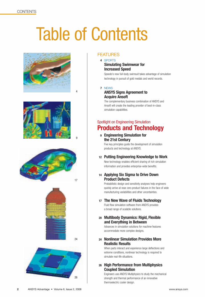
Spotlight on Engineering Simulation
Products and Technology9 Engineering Simulation for
the 21st CenturyFive key principles guide the development of simulation products and technology at ANSYS.
12 Putting Engineering Knowledge to WorkNew technology enables efficient sharing of rich simulation
information and provides enterprise-wide benefits.
14 Applying Six Sigma to Drive DownProduct Defects Probabilistic design and sensitivity analyses help engineersquickly arrive at near-zero product failures in the face of widemanufacturing variabilities and other uncertainties.
17 The New Wave of Fluids TechnologyFluid flow simulation software from ANSYS provides a broad range of scalable solutions.
20 Multibody Dynamics: Rigid, Flexible and Everything in BetweenAdvances in simulation solutions for machine features accommodate more complex designs.
24 Nonlinear Simulation Provides MoreRealistic ResultsWhen parts interact and experience large deflections andextreme conditions, nonlinear technology is required to simulate real-life situations.
26 High Performance from MultiphysicsCoupled SimulationEngineers use ANSYS Multiphysics to study the mechanicalstrength and thermal performance of an innovative thermoelectric cooler design.
24
26
www.ansys.comANSYS Advantage • Volume II, Issue 2, 20082
CONTENTS
Table of ContentsFEATURES
4 SPORTS
Simulating Swimwear for Increased SpeedSpeedo’s new full-body swimsuit takes advantage of simulation
technology in pursuit of gold medals and world records.
7 NEWS
ANSYS Signs Agreement to Acquire Ansoft The complementary business combination of ANSYS andAnsoft will create the leading provider of best-in-class simulation capabilities.
17
9
4
ANSYS Advantage • Volume II, Issue 2, 2008www.ansys.com 3
CONTENTS
3
5238
Recently we asked you, the readers of ANSYS Advantage, for help in charting the magazine’s path to the future.Your response was overwhelming. Thanks for taking the time to share your opinions and comments.
We now have a better understanding of your needs and are already implementing some of your suggestions. You’llsee some changes to the magazine in this and upcoming issues. For instance, we’ve already started a new section —Outside the Box — which, in each issue, will report on some aspect of simulation with a human interest slant. We hope you enjoy it. Other changes will be coming in subsequent issues.
As for the winners of the navigation prizes — GPS unit and compasses — they were Stéphane Trehorel of Geo Technology S.A., Andreas Wiese of ELAU AG and Stefan Jelenko of Litostroj E.I. Congratulations!
Although the survey is officially over, we are always happy to receive your suggestions or your article submissions.Send an email to [email protected] at any time. We look forward to hearing from you.
SIMULATION @ WORK29 MARINE
Getting the Mast from Virtual PrototypingStructural simulation tools help optimize main mast weight to increase megayacht sailing performance.
31 ELECTROMAGNETICS
Predicting Charged Particle TrajectoriesSimulation helps researchers obtain electromagnetic field solutions for predicting charged particle trajectories in a widerange of industrial, medical and research applications.
35 CONSUMER PRODUCTS
Flush with SuccessA toilet discharge valve is optimized to reduce household water consumption and maintain performance.
36 TRANSPORTATION
Adapting A High-Speed Train to Winter in RussiaSimulation helps prevent traction problems forrail travel during extreme weather conditions.
38 BIOMEDICAL
Understanding the Dangers of AneurysmsSimulation is used to validate measured blood flow in cerebral aneurysms.
DEPARTMENTS40 BOOK REVIEWS
Learning to Work with ANSYS WorkbenchTutorials help novices and experienced users alike understand the ins and outs of this simulation platform.
42 ACADEMIC
Simulation-Driven Teaching and ResearchAcademic products from ANSYS at release 11.0 are helping train future engineers.
46 TIPS & TRICKS
Using New Meshing Features in ANSYS Workbench SimulationKnowing when and how to apply key features of the latest structural meshing tools can result in greater efficiency.
49 TIPS & TRICKS
Coupling Momentum and ContinuityIncreases CFD RobustnessFLUENT technology introduces a pressure-based coupledsolver to reduce computation time for low-speed compressible and incompressible flow applications.
52 OUTSIDE THE BOX
Fluid Dynamics on the Big ScreenFluid simulations have come of age in the world of movie-making.
Thanks for Helping Us Navigate
www.ansys.comANSYS Advantage • Volume II, Issue 2, 20084
FEATURE: SPORTS
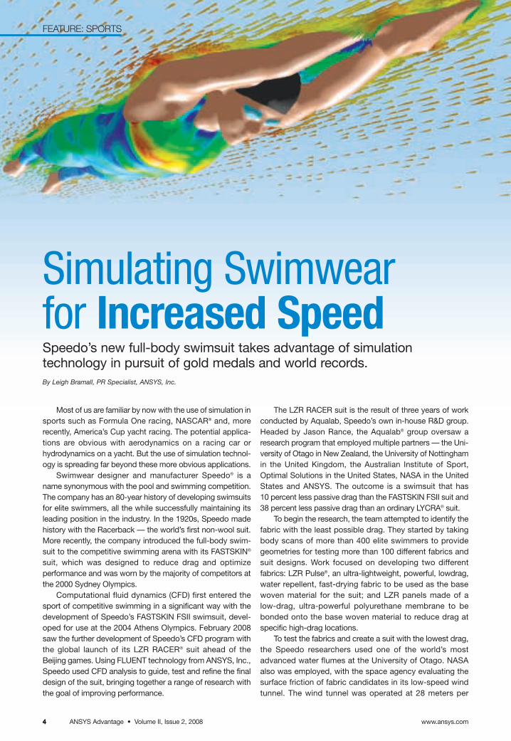
Simulating Swimwearfor Increased SpeedSpeedo’s new full-body swimsuit takes advantage of simulation technology in pursuit of gold medals and world records.By Leigh Bramall, PR Specialist, ANSYS, Inc.
Most of us are familiar by now with the use of simulation insports such as Formula One racing, NASCAR® and, morerecently, America’s Cup yacht racing. The potential applica-tions are obvious with aerodynamics on a racing car orhydrodynamics on a yacht. But the use of simulation technol-ogy is spreading far beyond these more obvious applications.
Swimwear designer and manufacturer Speedo® is aname synonymous with the pool and swimming competition.The company has an 80-year history of developing swimsuitsfor elite swimmers, all the while successfully maintaining itsleading position in the industry. In the 1920s, Speedo madehistory with the Racerback — the world’s first non-wool suit.More recently, the company introduced the full-body swim-suit to the competitive swimming arena with its FASTSKIN®
suit, which was designed to reduce drag and optimize performance and was worn by the majority of competitors atthe 2000 Sydney Olympics.
Computational fluid dynamics (CFD) first entered thesport of competitive swimming in a significant way with thedevelopment of Speedo’s FASTSKIN FSII swimsuit, devel-oped for use at the 2004 Athens Olympics. February 2008saw the further development of Speedo’s CFD program withthe global launch of its LZR RACER® suit ahead of the Beijing games. Using FLUENT technology from ANSYS, Inc.,Speedo used CFD analysis to guide, test and refine the finaldesign of the suit, bringing together a range of research withthe goal of improving performance.
The LZR RACER suit is the result of three years of workconducted by Aqualab, Speedo’s own in-house R&D group.Headed by Jason Rance, the Aqualab® group oversaw aresearch program that employed multiple partners — the Uni-versity of Otago in New Zealand, the University of Nottinghamin the United Kingdom, the Australian Institute of Sport, Optimal Solutions in the United States, NASA in the UnitedStates and ANSYS. The outcome is a swimsuit that has 10 percent less passive drag than the FASTSKIN FSII suit and38 percent less passive drag than an ordinary LYCRA® suit.
To begin the research, the team attempted to identify thefabric with the least possible drag. They started by takingbody scans of more than 400 elite swimmers to providegeometries for testing more than 100 different fabrics andsuit designs. Work focused on developing two different fabrics: LZR Pulse®, an ultra-lightweight, powerful, lowdrag,water repellent, fast-drying fabric to be used as the basewoven material for the suit; and LZR panels made of a low-drag, ultra-powerful polyurethane membrane to bebonded onto the base woven material to reduce drag at specific high-drag locations.
To test the fabrics and create a suit with the lowest drag,the Speedo researchers used one of the world’s mostadvanced water flumes at the University of Otago. NASAalso was employed, with the space agency evaluating thesurface friction of fabric candidates in its low-speed windtunnel. The wind tunnel was operated at 28 meters per
4
FEATURE: SPORTS
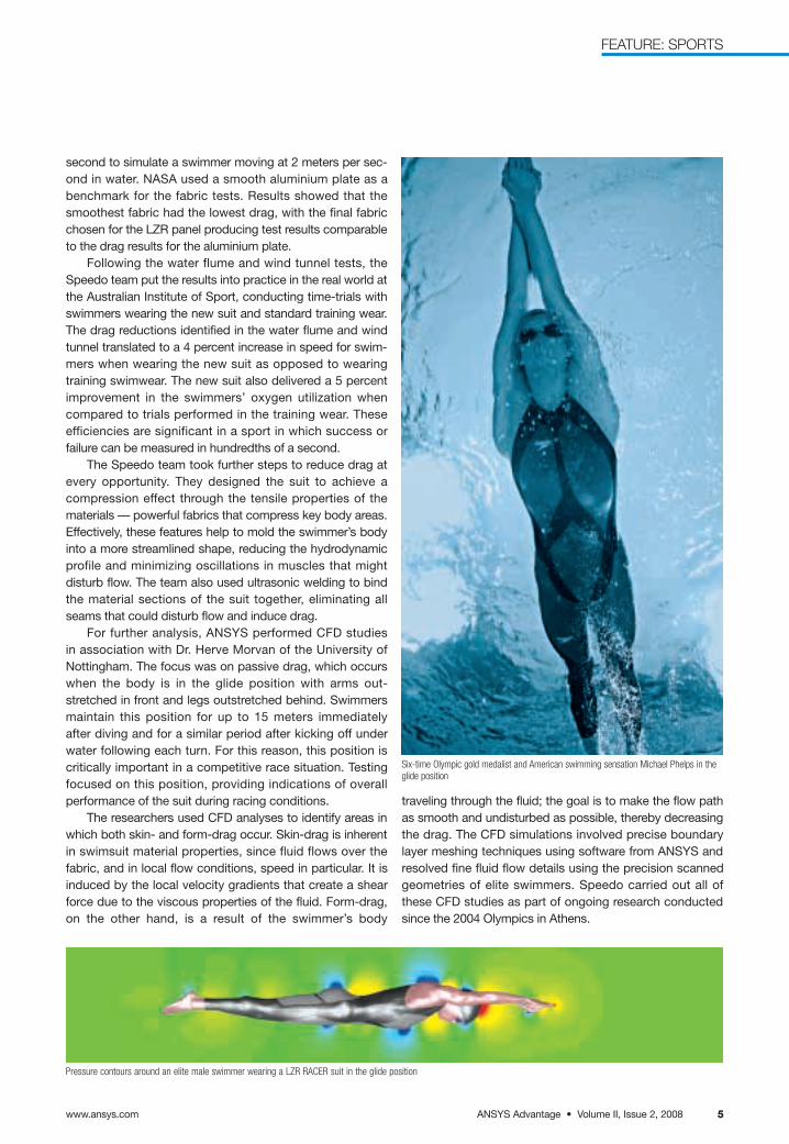
Pressure contours around an elite male swimmer wearing a LZR RACER suit in the glide position
Six-time Olympic gold medalist and American swimming sensation Michael Phelps in theglide position
ANSYS Advantage • Volume II, Issue 2, 2008www.ansys.com 55
traveling through the fluid; the goal is to make the flow pathas smooth and undisturbed as possible, thereby decreasingthe drag. The CFD simulations involved precise boundarylayer meshing techniques using software from ANSYS andresolved fine fluid flow details using the precision scannedgeometries of elite swimmers. Speedo carried out all ofthese CFD studies as part of ongoing research conductedsince the 2004 Olympics in Athens.
second to simulate a swimmer moving at 2 meters per sec-ond in water. NASA used a smooth aluminium plate as abenchmark for the fabric tests. Results showed that thesmoothest fabric had the lowest drag, with the final fabricchosen for the LZR panel producing test results comparableto the drag results for the aluminium plate.
Following the water flume and wind tunnel tests, theSpeedo team put the results into practice in the real world atthe Australian Institute of Sport, conducting time-trials withswimmers wearing the new suit and standard training wear.The drag reductions identified in the water flume and windtunnel translated to a 4 percent increase in speed for swim-mers when wearing the new suit as opposed to wearingtraining swimwear. The new suit also delivered a 5 percentimprovement in the swimmers’ oxygen utilization when compared to trials performed in the training wear. These efficiencies are significant in a sport in which success or failure can be measured in hundredths of a second.
The Speedo team took further steps to reduce drag atevery opportunity. They designed the suit to achieve a compression effect through the tensile properties of thematerials — powerful fabrics that compress key body areas.Effectively, these features help to mold the swimmer’s bodyinto a more streamlined shape, reducing the hydrodynamicprofile and minimizing oscillations in muscles that might disturb flow. The team also used ultrasonic welding to bindthe material sections of the suit together, eliminating allseams that could disturb flow and induce drag.
For further analysis, ANSYS performed CFD studies in association with Dr. Herve Morvan of the University of Nottingham. The focus was on passive drag, which occurswhen the body is in the glide position with arms out-stretched in front and legs outstretched behind. Swimmersmaintain this position for up to 15 meters immediately after diving and for a similar period after kicking off underwater following each turn. For this reason, this position is critically important in a competitive race situation. Testingfocused on this position, providing indications of overall performance of the suit during racing conditions.
The researchers used CFD analyses to identify areas inwhich both skin- and form-drag occur. Skin-drag is inherentin swimsuit material properties, since fluid flows over the fabric, and in local flow conditions, speed in particular. It isinduced by the local velocity gradients that create a shearforce due to the viscous properties of the fluid. Form-drag,on the other hand, is a result of the swimmer’s body
ANSYS Advantage • Volume II, Issue 2, 20086
FEATURE: SPORTS
6
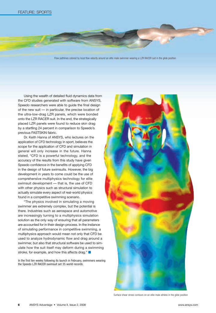
Flow pathlines colored by local flow velocity around an elite male swimmer wearing a LZR RACER suit in the glide position
www.ansys.com
Using the wealth of detailed fluid dynamics data from the CFD studies generated with software from ANSYS,Speedo researchers were able to guide the final designof the new suit — in particular, the precise location ofthe ultra-low-drag LZR panels, which were bondedonto the LZR RACER suit. In the end, the strategicallyplaced LZR panels were found to reduce skin dragby a startling 24 percent in comparison to Speedo’sprevious FASTSKIN fabric.
Dr. Keith Hanna of ANSYS, who lectures on theapplication of CFD technology in sport, believes thescope for the application of CFD and simulation ingeneral will only increase in the future. Hanna stated, “CFD is a powerful technology, and theaccuracy of the results from this study have givenSpeedo confidence in the benefits of applying CFDin the design of future swimsuits. However, the bigdevelopment in years to come could be the use ofcomprehensive multiphysics technology for eliteswimsuit development — that is, the use of CFDwith other physics such as structural simulation toactually simulate every aspect of real-world physicsfound in a competitive swimming scenario.
“The physics involved in simulating a movingswimmer are extremely complex, but the potential isthere. Industries such as aerospace and automotiveare increasingly turning to a multiphysics simulationsolution as the only way of ensuring that all parametersare accounted for in their design process. In the instanceof simulating performance in competitive swimming, amultiphysics approach would mean not only that CFD beused to analyze hydrodynamic flow and drag around aswimmer, but also that structural software be used to sim-ulate how the suit itself may deform during a swimmingstroke, for example, and how this affects drag.” ■
In the first ten weeks following its launch in February, swimmers wearingthe Speedo LZR RACER swimsuit set 35 world records.
Surface shear stress contours on an elite male athlete in the glide position
ANSYS, Inc. and Ansoft Corpora-tion, a global provider of electronicdesign automation (EDA) software,announced on March 31 that a definitiveagreement was signed in which ANSYSwill acquire Ansoft for a purchase priceof approximately $832 million. Ansoft isa leading developer of high-performanceEDA software, which is based on morethan 25 years of research and develop-ment by world-renowned experts inelectromagnetics, circuit and systemsimulation. Engineers use Ansoft products to simulate high-performanceelectronics designs found in mobilecommunication and Internet devices,broadband networking components andsystems, integrated circuits, printed circuit boards and electromechanicalsystems. Products from Ansoft are usedby blue chip companies as well as smalland medium-sized enterprises aroundthe world.
The acquisition of Ansoft is the firstforay for ANSYS into the broader EDAsoftware industry and will enhance thebreadth, functionality, usability andinteroperability of the combined ANSYSportfolio of engineering simulation solu-tions. The combination is expected toincrease operational efficiency andlower design and engineering costs for customers, as well as accelerate
development and delivery of new andinnovative products to the marketplace;it also is expected to give ANSYS one of the most complete, independent engineering simulation software off-erings in the industry. This reaffirms andstrengthens the ANSYS commitment toopen interface and flexible simulationsolutions that are driven primarily bycustomer demand, flexibility and choice.With more than 40 direct sales officesand 21 development centers on threecontinents, the combined company willemploy approximately 1,700 people.
“We are very excited about thestate-of-the-art technologies that Ansoftadds to the simulation capabilities ofANSYS,” said James E. Cashman III,president and chief executive officer ofANSYS, Inc. “Both companies have astrong commitment to their customersand employees, share a passion for the development of innovative products and services, and have a history ofworld-class execution. It expands ourofferings into electronic designs, a critical area. Now we can bring the rich-est engineering calculations to predicthow a product will perform in the realworld. Electronics and the electro-magnetic field are obviously a big part ofthat. With Ansoft, we can take a com-plete system and the entire environment
and allow designers to evaluate theirentire product.”
“This merger brings together twogreat companies with a shared visionand strong engineering focus,” said Dr.Zoltan J. Cendes, the founder, chairmanof the board and chief technology officerof Ansoft Corporation. “The combina-tion of our R&D teams, complementarytechnological strengths and commit-ment to quality will enhance our abilityto deliver comprehensive, innovative,world-class simulation software tech-nologies that customers demand.”
“We are excited about bringing twogreat Pittsburgh-based companiestogether to create an exciting oppor-tunity for aspiring engineers, computerscientists and professionals to join us in our mission to democratize the use of simulation across the globe,”added Cashman. ■
ANSYS Signs Agreement to Acquire AnsoftThe complementary business combination of ANSYS and Ansoft will create the leading provider of best-in-class simulation capabilities.
ANSYS Advantage • Volume II, Issue 2, 2008www.ansys.com 7
NEWS

www.ansys.comANSYS Advantage • Volume II, Issue 2, 20088
ANSYS Advantage • Volume II, Issue 2, 2008www.ansys.com 99
PRODUCTS & TECHNOLOGY: OVERVIEW
www.ansys.com 9
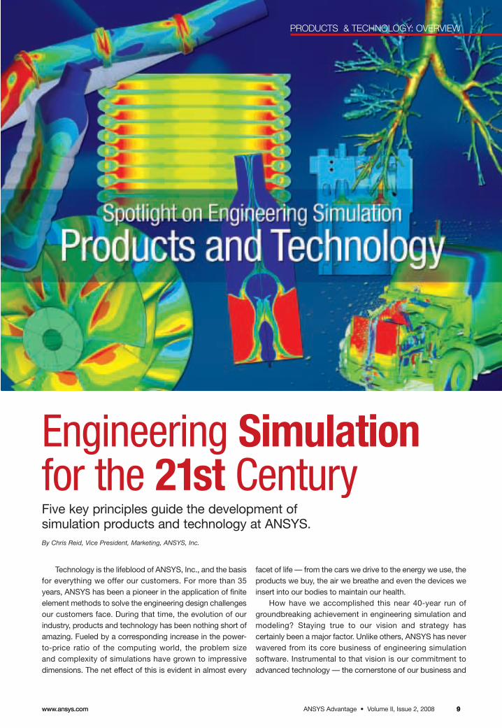
Engineering Simulationfor the 21st CenturyFive key principles guide the development of simulation products and technology at ANSYS.By Chris Reid, Vice President, Marketing, ANSYS, Inc.
Technology is the lifeblood of ANSYS, Inc., and the basisfor everything we offer our customers. For more than 35years, ANSYS has been a pioneer in the application of finiteelement methods to solve the engineering design challengesour customers face. During that time, the evolution of ourindustry, products and technology has been nothing short ofamazing. Fueled by a corresponding increase in the power-to-price ratio of the computing world, the problem size and complexity of simulations have grown to impressivedimensions. The net effect of this is evident in almost every
facet of life — from the cars we drive to the energy we use, theproducts we buy, the air we breathe and even the devices weinsert into our bodies to maintain our health.
How have we accomplished this near 40-year run ofgroundbreaking achievement in engineering simulation andmodeling? Staying true to our vision and strategy has certainly been a major factor. Unlike others, ANSYS has neverwavered from its core business of engineering simulationsoftware. Instrumental to that vision is our commitment toadvanced technology — the cornerstone of our business and
www.ansys.comANSYS Advantage • Volume II, Issue 2, 200810 www.ansys.comANSYS Advantage • Volume II, Issue 1, 200810
PRODUCTS & TECHNOLOGY: OVERVIEW
value to our customers. After all, it is our products andtechnology that enable companies to create the mostinnovative and globally competitive products for their industry.
Also instrumental to our vision are five principlesthat guide the development of our products and tech-nologies. The first is unequalled depth. Simply stated,for each of the key areas of simulation and modelingtechnologies — whether it be mechanical, fluid flow,thermal, electromagnetics, meshing or others — weoffer a depth of capability that is second to none. Thisdepth has been created over time by reinvesting inthe research and development of new technologies,and supplemented by key acquisitions and partner-ships along the way. Today, the results speak forthemselves in the richness of what we offer our cus-tomers, regardless of their specific simulationrequirements.
The second guiding principle is unparalleledbreadth. In this regard, ANSYS has assembled a complete range of simulation capabilities — from pre-processing to multiple physics to knowledgemanagement. Our customers see this as a tremen-dous benefit, because they know we can provide asolution for each specific area of analysis and that weprovide rich depth across our entire portfolio of prod-ucts and technologies. Some companies, perhaps,can lay claim to this in one or two areas, but we offerthis depth and breadth for the full range of simulationand modeling techniques.
In offering both technological depth and breadth,our customers are able to run simulations that are more sophisticated, more complex and more representative of the real world. Utilizing such a comprehensive multiphysics approach — our thirdguiding principle — enables engineers to simulate andanalyze complete systems or subsystems using truevirtual prototyping. Increasingly, companies realize thata multiphysics approach is essential to attain the mostaccurate and realistic simulation of a new product orprocess design. At ANSYS, we not only provide the technologies to do this, but we make them all interoperable within the unified ANSYS Workbenchenvironment. Thus, the user can configure a multiphysics analysis and avoid the need for cumber-some file transfers or intermediate third-party software links. Our technology inherently provides the
infrastructure, saving implementation time whileproviding measurable benefits in speed and robustnessas well.
The old adage “one size fits all” is certainly not the case in the world of engineering simulation.Despite the common threads that appear everywheresimulation is used, there are also real differences.Some industries, such as automotive and aerospace,are mature in their use of these tools, while others,such as healthcare, are relative newcomers. Compa-nies within the same industry can be at markedlydifferent stages of adoption, and users within any onecompany may have vastly different needs or experi-ence with simulation tools. There is a need forflexibility. Customers must be able to adopt theappropriate level of simulation and know they willhave latitude in how they move forward.
At ANSYS, we call this engineered scalability —guiding principle number four. Why “engineered”?Our scalability is by design and is specifically engi-neered into the technology we have developed. Thedepth of our technology allows customers to choosethe appropriate level of technology for their needs yetscale upward as their requirements evolve and grow.If the customer is a small company with just a desktopor modest compute resources, or if it is large withhundreds of machines in large-scale compute clus-ters, our software runs efficiently and brings value. Ina similar vein, if the number of users is very small or inthe hundreds, scalable deployment has been factoredin. Likewise, if the customer is an infrequent user, adesigner who wants to perform a simple simulation oran expert analyst, we have the appropriate level oftool for each of those levels of experience. Underpin-ning this seamless range of capability — from theautomated to the most sophisticated and customiz-able — is the same advanced technology, scaled upor down accordingly.
Technology isn’t of much use to the customer if it’sextremely inflexible to apply, scalable or otherwise. Allof it must be usable in a way that makes sense for thecompany and its design and development processes,as well as alongside other programs it may haveselected for their engineering systems strategy. Thevision needs to be flexible and adaptive, not rigid andconstraining. In this regard, ANSYS adheres to a fun-damental tenet of adaptive architecture — the fifth
ANSYS Advantage • Volume II, Issue 2, 20081010 www.ansys.com
ANSYS Advantage • Volume II, Issue 2, 2008www.ansys.com 1111
PRODUCTS & TECHNOLOGY: OVERVIEW
guiding principle. We recognize the mission-criticalnature of what we provide and also how crucial it isthat our technology fits within the customer’s overallsystem. There can be CAD systems, selected third-party codes for niche applications, or legacy andin-house software, all of which remain critical compo-nents of the overall process. We need to coexist withthese and, in fact, enable them to be included in theoverall workflow as painlessly as possible.
Many companies are investing in product lifecyclemanagement (PLM) systems. These constitute a majorinvestment and require data exchange with the simulation software. The ANSYS Workbench platformand the new ANSYS Engineering Knowledge Manager(EKM) technology are designed to provide functionalcoexistence with PLM systems, which actuallyimproves their value to the customer. Adaptive architecture means what it says — ANSYS productsand technology can adapt to the customer’s specific
situation. We can be the backbone, coexist peer-to-peer or be a plug-in, whatever the need may be.
Five simple phrases — unequalled depth, unparal-leled breadth, comprehensive multiphysics, engineeredscalability and adaptive architecture. These five tenetsare what drive our product development strategy withevery dollar we invest. We also think they are the reasonthat 96 of the top 100 industrial companies on the FORTUNE Global 500 list, as well as another 13,000customers around the world, use technology fromANSYS. The ANSYS simulation community today is the world’s largest, and by continuing to pursue ourstrategy of Simulation Driven Product Development andadhering to these five guiding principles, we see no reason why our vision of placing simulation tools in thehands of every engineer shouldn’t become a reality inthe near future. ■
Images courtesy Tusas Engine Industries, Silesian University of Technology, Cummins,Inc., FluidDA nv, Modine Manufacturing Company and © 2008 Owens Corning Science & Technology, LLC and the Gas Technology Institute. Used with permission.
www.ansys.comANSYS Advantage • Volume II, Issue 2, 200812
PRODUCTS & TECHNOLOGY: DATA MANAGEMENT
The last three decades have witnessed the evolution ofcomputer-aided engineering (CAE) from a tool used by analysts in a research and development department to onethat is integral to the entire product design and lifecycleprocess. Companies around the world are making greateruse of upfront analysis and complex system simulation.With the ongoing integration of CAE into the designprocess, the focus is shifting from technology issues suchas improved simulation techniques, physics modeling andease-of-use to usage-focused questions such as “How do I better manage and share the voluminous data that is beinggenerated?” or “How do I better capture the engineeringexpertise that the simulation results represent?” The answerto these questions is often referred to as simulation processand data management (SPDM).
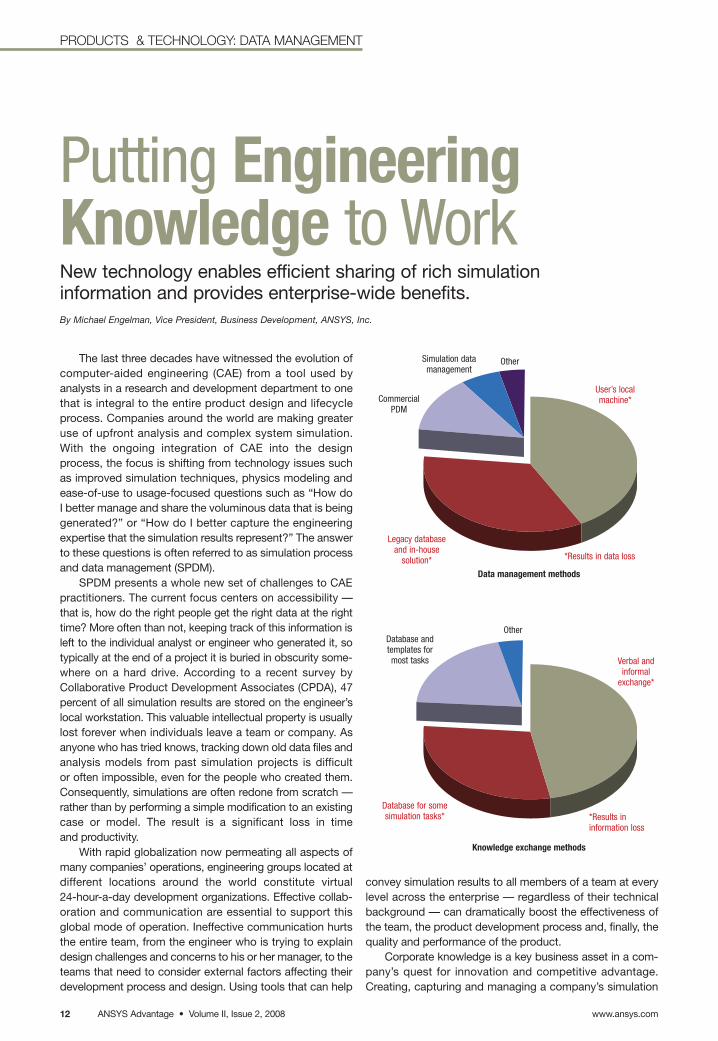
SPDM presents a whole new set of challenges to CAEpractitioners. The current focus centers on accessibility —that is, how do the right people get the right data at the righttime? More often than not, keeping track of this information isleft to the individual analyst or engineer who generated it, sotypically at the end of a project it is buried in obscurity some-where on a hard drive. According to a recent survey byCollaborative Product Development Associates (CPDA), 47percent of all simulation results are stored on the engineer’slocal workstation. This valuable intellectual property is usuallylost forever when individuals leave a team or company. Asanyone who has tried knows, tracking down old data files andanalysis models from past simulation projects is difficult or often impossible, even for the people who created them. Consequently, simulations are often redone from scratch —rather than by performing a simple modification to an existingcase or model. The result is a significant loss in time and productivity.
With rapid globalization now permeating all aspects ofmany companies’ operations, engineering groups located atdifferent locations around the world constitute virtual 24-hour-a-day development organizations. Effective collab-oration and communication are essential to support this global mode of operation. Ineffective communication hurtsthe entire team, from the engineer who is trying to explaindesign challenges and concerns to his or her manager, to theteams that need to consider external factors affecting theirdevelopment process and design. Using tools that can help
convey simulation results to all members of a team at everylevel across the enterprise — regardless of their technicalbackground — can dramatically boost the effectiveness ofthe team, the product development process and, finally, thequality and performance of the product.
Corporate knowledge is a key business asset in a com-pany’s quest for innovation and competitive advantage.Creating, capturing and managing a company’s simulation
Putting EngineeringKnowledge to WorkNew technology enables efficient sharing of rich simulationinformation and provides enterprise-wide benefits.By Michael Engelman, Vice President, Business Development, ANSYS, Inc.
Data management methods
Database andtemplates formost tasks
Database for somesimulation tasks*
Simulation datamanagement
CommercialPDM
Legacy databaseand in-house
solution*
User’s localmachine*
Other
Verbal and informal
exchange*
*Results in information loss
*Results in data loss
Other
Knowledge exchange methods
ANSYS Advantage • Volume II, Issue 2, 2008www.ansys.com 13
PRODUCTS & TECHNOLOGY: DATA MANAGEMENT
expertise is critical to enabling innovation. It empowers usersto build on previous experience and fosters continualimprovement and collaboration of the expert analysts anddesign engineers. Effective process management tools thatcapture simulation best practices, deploy managed simula-tion tasks and processes, and plug into internal applicationswithin a unified environment are essential to achieve thesegoals — though they must also require minimal effort andmaintenance costs.
Managing simulation data and processes within this context is a specialized subset of the broader product lifecycle management (PLM) vision. This discipline is based onthe digital management of all aspects of a product’s lifecycle,from concept and design through manufacture, deployment,maintenance and eventual disposal. Unfortunately, thoseneeds that are specific to simulation and SPDM are oftenoverlooked or poorly addressed by today’s PLM systems. Thisis a result of SPDM being more demanding than the file/document-centric approach of PLM and related product datamanagement (PDM) systems. Simulation data is richer, morecomplex and typically many orders of magnitude larger than
other types of product data. An SPDM system is comple-mentary to a PLM system and can add significant value whendesigned to work in close conjunction with PLM.
The ANSYS Engineering Knowledge Manager (EKM)technology, now in its initial release, is aimed at meeting thesechallenges with extensive capabilities: archiving and manage-ment of simulation data, traceability and audit trail, advancedsearch and retrieval, report generation and simulation com-parison, process/workflow automation, and capture anddeployment of best practices. It is a Web-based SPDMframework aimed at hosting all simulation data, workflowsand tools, whether in-house or commercial, while maintaininga tight connection between them. While providing seamlessintegration with simulation products from ANSYS — includingthe ability to automatically extract and organize extensiveinformation about ANSYS software–based simulation fileswhen they are uploaded into the repository — the ANSYSEKM tool is an open system that can manage any type of in-house or third-party simulation products, files or infor-mation as well. Moreover, it is a scalable solution that can beeffectively used by small workgroups, distributed teams ofengineers or the entire enterprise.
With tools and developers that have histories stretchingback to the formative years of simulation, ANSYS under-stands the complexity and challenges of simulation. ANSYSEKM technology was created with an appreciation thataccess to simulation; developing effective processes forincorporating simulation into individual, workgroup and enterprise-wide efforts; and managing simulation efforts within a larger development or industrial process is a compli-cated effort — one that can be made simpler. Having accessto the right tools, developed by a team that has devoted yearsto understanding the challenges of simulation, can streamlinethe incorporation of virtual product development efforts intotraditional workflows and environments. Adding ANSYS EKMtools to the capabilities of the family of products from ANSYSempowers organizations of all sizes to better achieve the goal of Simulation Driven Product Development. ■
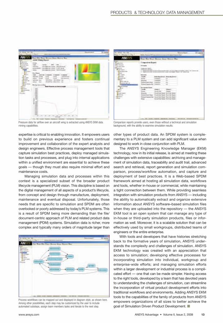
Process workflows can be mapped out and displayed in diagram style, as shown here.Among other possibilities, each step may be customized by the user to include automated substeps, assign team members tasks and iterate to the next step.
Pressure data for airflow over an aircraft wing is extracted using ANSYS EKM data mining capabilities.
Comparison reports provide users, even those without a technical and simulation background, with the ability to examine simulation results.
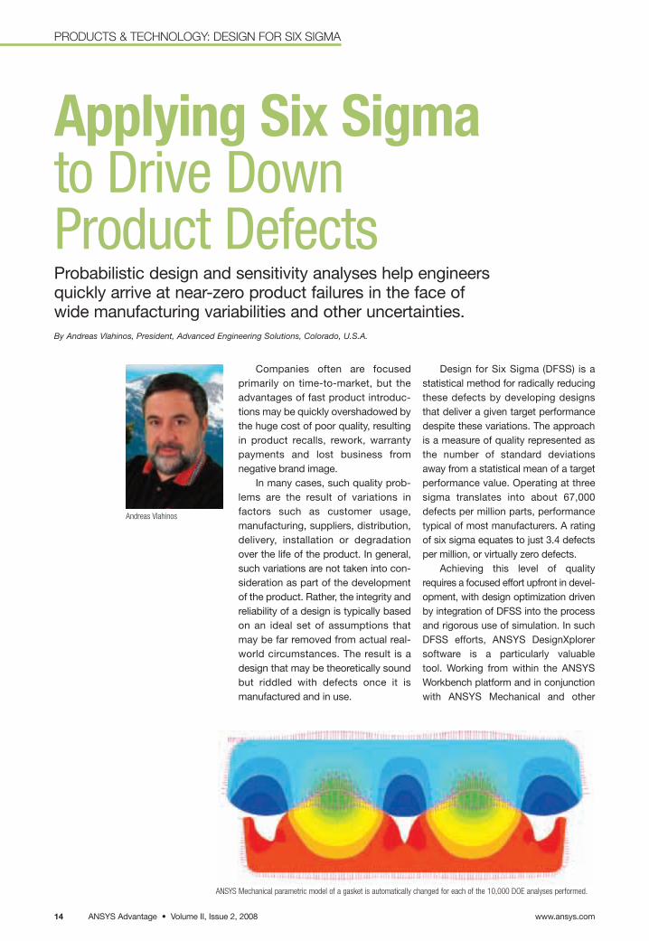
Applying Six Sigmato Drive Down Product DefectsProbabilistic design and sensitivity analyses help engineers quickly arrive at near-zero product failures in the face of wide manufacturing variabilities and other uncertainties.By Andreas Vlahinos, President, Advanced Engineering Solutions, Colorado, U.S.A.
Companies often are focused primarily on time-to-market, but theadvantages of fast product introduc-tions may be quickly overshadowed bythe huge cost of poor quality, resultingin product recalls, rework, warrantypayments and lost business from negative brand image.
In many cases, such quality prob-lems are the result of variations infactors such as customer usage, manufacturing, suppliers, distribution,delivery, installation or degradationover the life of the product. In general,such variations are not taken into con-sideration as part of the developmentof the product. Rather, the integrity andreliability of a design is typically basedon an ideal set of assumptions thatmay be far removed from actual real-world circumstances. The result is adesign that may be theoretically soundbut riddled with defects once it is manufactured and in use.
ANSYS Mechanical parametric model of a gasket is automatically changed for each of the 10,000 DOE analyses performed.
Andreas Vlahinos
Design for Six Sigma (DFSS) is astatistical method for radically reducingthese defects by developing designsthat deliver a given target performancedespite these variations. The approachis a measure of quality represented asthe number of standard deviationsaway from a statistical mean of a targetperformance value. Operating at threesigma translates into about 67,000defects per million parts, performancetypical of most manufacturers. A ratingof six sigma equates to just 3.4 defectsper million, or virtually zero defects.
Achieving this level of qualityrequires a focused effort upfront in devel-opment, with design optimization drivenby integration of DFSS into the processand rigorous use of simulation. In suchDFSS efforts, ANSYS DesignXplorersoftware is a particularly valuable tool. Working from within the ANSYS Workbench platform and in conjunctionwith ANSYS Mechanical and other
www.ansys.comANSYS Advantage • Volume II, Issue 2, 200814
PRODUCTS & TECHNOLOGY: DESIGN FOR SIX SIGMA
ANSYS Advantage • Volume II, Issue 2, 2008www.ansys.com 1515
PRODUCTS & TECHNOLOGY: DESIGN FOR SIX SIGMA
simulation software, the program per-forms Design of Experiments (DOE) anddevelops probabilistic design analysesfunctions to determine the extent towhich variabilities of key parametersimpact product performance.
The process is accomplished infour major phases: process automation,design exploration, design optimizationand robust design. Utilizing the ANSYSWorkbench environment, process auto-mation ensures that simulation tasksare well defined and flow automaticallyto extract and evaluate key perform-ance variables.
ANSYS DesignXplorer softwarethen performs the DOE, running numer-ous (usually thousands) analyses usingvarious combinations of these param-eters. The ability to quickly andeffortlessly execute such an extensivestudy on this wide range of parametersallows users to perform quick andaccurate what-if scenarios to testdesign ideas. In this way, design explo-ration — combined with knowledge,best practices and experience — is apowerful decision-making tool in theDFSS process.
Next, design optimization is per-formed with the ANSYS DesignXplorertool in order to select the alternativedesigns available within the acceptablerange of performance variables. Designparameters are set to analyze all possi-bilities — including those that mightpush the design past constraints andviolate design requirements. Finally,robust design is performed, arriving atthe best possible design that accountsfor variabilities and satisfactorily meetstarget performance requirements.
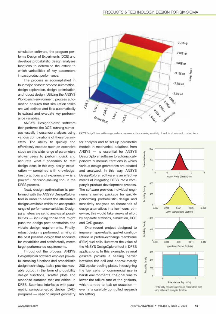
Throughout the process, ANSYSDesignXplorer software employs power-ful sampling functions and probabilisticdesign technology. It also provides valu-able output in the form of probabilitydesign functions, scatter plots andresponse surfaces that are critical inDFSS. Seamless interfaces with para-metric computer-aided design (CAD)programs — used to import geometry
for analysis and to set up parametricmodels in mechanical solutions fromANSYS — is essential for ANSYSDesignXplorer software to automaticallyperform numerous iterations in whichvarious design geometries are createdand analyzed. In this way, ANSYSDesignXplorer software is an effectivemeans of integrating DFSS into a com-pany’s product development process.The software provides individual engi-neers a unified package for quicklyperforming probabilistic design andsensitivity analyses on thousands ofdesign alternatives in a few hours; oth-erwise, this would take weeks of effortby separate statistics, simulation, DOEand CAD groups.
One recent project designed toimprove hyper-elastic gasket configu-rations in proton-exchange membrane(PEM) fuel cells illustrates the value ofthe ANSYS DesignXplorer tool in DFSSapplications. In this example, severalgaskets provide a sealing barrierbetween the cell and approximately200 bipolar cooling plates. In designingthe fuel cells for commercial use inharsh environments, the goal was tolower the failure rate of the gaskets,which tended to leak on occasion —even in a carefully controlled researchlab setting.
Probability density functions of parameters thatvary with each analysis iteration
1000
500
0
1000
500
0
1000
500
0
600
400
200
0
-4 -2 0 2 4
0.022 0.023 0.024 0.025 0.026
0.008 0.009 0.01 0.011 0.012
0 1 2
Prob
abili
ty D
ensi
ty
Gasket Profile Offset (10-3 in)
Plate Interface Gap (10-3 in)
Lower Gasket Groove Depth (in)
Upper Gasket Groove Depth (in)
Prob
abili
ty D
ensi
tyPr
obab
ility
Den
sity
Prob
abili
ty D
ensi
ty
Gask
et F
orce
Gasket P
rofile
Groove Depth
-2.75E+0
-2.88E+0
-3.01E+0
-3.15E+0
-3.28E+0
-3.24E+0
2.20
E-2
2.28
E-2
2.36
E-2
2.44
E-2
2.52
E-2
4.00E-32.40E-38.00E-4-8.00E-4
-2.400E-3
ANSYS DesignXplorer software generated a response surface showing sensitivity of each input variable to contact force.

www.ansys.comANSYS Advantage • Volume II, Issue 2, 200816
PRODUCTS & TECHNOLOGY: DESIGN FOR SIX SIGMA
Scatter plots of analysis results were generated, along with bell-shaped probability density functions,in arriving at a robust gasket design.
With the workflow captured in the ANSYS Workbench platform, the process is highly repeatable and can be efficientlyapplied in optimizing the design of other gaskets.
First, design variables were estab-lished — gasket profile, gasket groovedepth and the opposing plate’srecessed pocket groove depth — thatdetermined the overall compressiveforce of the gasket under a given boltload. These were considered to berandomly varying parameters withgiven mean and standard deviationsas determined through probabilitydensity functions generated by theANSYS DesignXplorer tool. The soft-ware then was set up to automaticallyperform a series of DOE analyses inorder to determine the gasket contactforce for 10,000 different combinationsof these variables. Variables were ran-domly selected by the software foreach round of analysis using the Latinhypercube sampling technique.
Using ANSYS Mechanical analy-sis, solutions were arrived at in which(1) nonlinear capabilities characterizethe hyper-elastic gasket materialproperties; (2) contact elements repre-sent contact between the gasket andplates; and (3) parametric featuresautomatically change the geometry of the gasket configuration for each ofthe 10,000 analyses.
Based on these analysis results,ANSYS DesignXplorer software generated a response surface of thecontact force per unit length of the gasket in terms of probabilisticinput variables. With the sensitivityestablished for each input variable onthe contact force, scatter plots of theanalysis results were generated alongwith bell-shaped probability densityfunctions, which were compared tothe upper and lower load limits of thefuel cell and cooler interfaces. Axialforces could not be so high as tobreak the plates, yet not so low as to cause leaking. From this data,the ANSYS DesignXplorer tool deter-mined the sigma quality level basedon the contact force target level.
The process succeeded in arriving at an optimal gasket shapethat exceeded the sigma qualitylevel, dropping the failure rate to animpressive three parts per million —
a tremendous improvement over the 20 percent failure rate that the gas-kets were experiencing previously.
The entire process — including creation of the mesh models and com-pletion of the 10,000 DOE analysiscycles — was completed in a matter ofdays by a single individual, as com-pared to months of effort thatotherwise would have been requiredby separate design, statistics andanalysis groups. Moreover, with theworkflow captured in the ANSYS
Workbench platform, the process now ishighly repeatable and can be efficientlyapplied in optimizing the design of othergaskets merely by changing the CADmodel and the upper/lower contactforce limits. ■
More detailed information on the DFSS gasketproject can be found in the ASME paper FuelCell 2006-97106 “Shape Optimization of FuelCell Molded-On Gaskets for Robust Sealing”by Vlahinos, Kelly, Mease and Stathopoulosfrom the International Conference on Fuel CellScience, Engineering and Technology, Irvine, CA,June 19–21, 2006.
Establish DesignVariables
Design of Experiments
ExperimentsParametric CAE Model
Probabilistic Response
Targets
Mean and StandardDeviation of Response
Variables
10K Random Experiments
Latin Hypercube SamplingMean and Standard Deviation
of Design Variables
Goodness of Fit
SigmaQuality Level
300
250
200
150
100
50
0
0.026
0.025
0.024
0.023
0.022
0.026
0.025
0.024
0.023
0.022
0.0080.026
0.024
0.022 -20
2
-2 -1 0 1 2
-2 -1 0 1 2 0 100 200 300
Gasket Profile Offset
Gasket Groove DepthGa
sket
Gro
ove
Dept
h
Gask
et G
roov
e De
pth
Rece
ssed
Poc
ket G
roov
e De
pth
Gasket Profile Offset
Gasket Profile Offset Probability Density
Prob
abili
ty D
ensi
tyx10-3
x10-3
x10-3
0.01
ResponseSurface
a system of high-fidelity multidomain analysis tools to truly
enable SDPD. SDPD is centered on the highly adaptive ANSYS
Workbench architecture. The next major ANSYS Workbenchrelease will provide another big step toward this vision. It willbe the first release in which a number of the original FluentCFD products will be data-integrated into the ANSYS Workbench platform, and thus the tools will work togetherwith various other applications from ANSYS.
The ANSYS Workbench approach allows ANSYS to provide a large variety of software choices tailored tomeet individual needs while ensuring interoperability and aclear future upgrade path. This includes a very broad fluids product line with all tools falling into one of three categories: general-purpose fluid flow analysis, rapid flowmodeling and industry-specific products.
General-Purpose Fluids SolversThe well-known FLUENT and ANSYS CFX products are
the main general-purpose CFD tools from ANSYS. These twosolvers, developed independently over decades, have a lot ofthings in common but also some significant differences. Both are control volume–based for high accuracy and relyheavily on a pressure-based solution technique for broadapplicability. They differ mainly in the way they integrate thefluid flow equations and in their equation solution strategies.
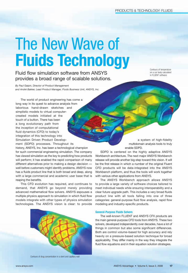
The world of product engineering has come along way in its quest to advance analysis fromlaborious hand-drawn sketches and simplistic models to virtual computer-created models initiated at thetouch of a button. There has beena long evolutionary path from the inception of computationalfluid dynamics (CFD) to today’s integration of this technology intoSimulation Driven Product Develop-ment (SDPD) processes. Throughout itshistory, ANSYS, Inc. has been a technological championfor such commercial engineering simulation. The companyhas viewed simulation as the key to predicting how productswill perform; it has enabled the rapid comparison of manydifferent alternatives prior to making a design decision —well before customers might identify problems. ANSYS nowhas a fluids product line that is both broad and deep, alongwith a large commercial and academic user base that isreaping the benefits.
This CFD evolution has required, and continues todemand, that ANSYS go beyond merely providingadvanced mathematical flow solvers. ANSYS espouses amultiple physics approach to simulation in which fluid flowmodels integrate with other types of physics simulationtechnologies. The ANSYS vision is clear: to provide
The New Wave of Fluids TechnologyFluid flow simulation software from ANSYS provides a broad range of scalable solutions.By Paul Galpin, Director of Product Management
and André Bakker, Lead Product Manager, Fluids Business Unit, ANSYS, Inc.
Contours of temperatureon a car body calculatedin FLUENT software
ANSYS Advantage • Volume II, Issue 2, 2008
PRODUCTS & TECHNOLOGY: FLUIDS
www.ansys.com 1717
Contours of drug concentration in a stent and capillary wall
Airflow in a datacenter as simulated using ANSYS Airpak software
The ANSYS CFX solver uses finite elements (cell vertexnumerics) to discretize the domain, similar to those used inthe mechanical analysis side of the business. In contrast,the FLUENT product uses finite volumes (cell-centerednumerics). Ultimately, though, both approaches form “control volume” equations that ensure exact conservationof flow quantities, a vital property for accurate CFD simula-tions. ANSYS CFX software focuses on one approach tosolve the governing equations of motion (coupled algebraicmultigrid), while the FLUENT solver offers several solutionapproaches (density-, segregated- and coupled pressure-based methods). Both solvers contain a wealth of physicalmodeling capabilities to ensure that any fluids simulationhas all of the modeling fidelity required.
These two core CFD solvers represent more than 1,000person-years of research and development. This efforttranslates into the key benefits of fluid flow analysis soft-ware from ANSYS: experience, trust, depth and breadth.The fluids core solvers from ANSYS are trusted, used andrelied upon by companies worldwide.
Rapid Flow ModelingANSYS addresses the fluid flow analysis needs of
designers, who work on the front lines of their company’sproduct development process and often need to makeimportant design decisions quickly with no time to set up andsolve complex mathematical models. For these time-limitedengineers, ANSYS offers a choice of rapid flow modeling(RFM) products. RFM technology from ANSYS compressesthe overall time it takes to do a fluid flow analysis by providing a high level of automation and focusing on only themost robust physical models. Three RFM tools are available:FloWizard, ANSYS CFX-Flo and FLUENT for CATIA®
V5 software.FloWizard software integrates all steps in the fluids
process into one smooth interface. Computer-aided design(CAD) files can be sent to the FloWizard product, flow volumes extracted, models set up, calculations completedand HTML reports generated. FloWizard software is fullycompatible with the FLUENT product, making it a goodchoice for designers in companies that use FLUENT tech-nology in the analysis department.
The ANSYS CFX-Flo tool is a version of ANSYS CFXsoftware that limits the physics accessible by the user to themodels most commonly used by design engineers. It is com-patible with other applicable ANSYS Workbench add-ins.The reduced complexity and cost of ANSYS CFX-Flo make ita good choice for design departments in organizations thatalready use ANSYS CFX software or other products com-patible with the ANSYS Workbench environment.
The FLUENT for CATIA V5 product offers many of thesame benefits of FloWizard and ANSYS CFX-Flo software.Completely embedded into the CATIA V5 system, it is fullycompatible with the standard, full FLUENT solver. It is mostuseful for companies that use CATIA V5 in their designdepartments and FLUENT software in their analysis groups.
Industry-Specific Fluids Simulation ToolsFlexibility and generality are important, but sometimes
not required for specific applications. In addition to providinggeneral-purpose CFD and rapid flow modeling products,ANSYS makes fluids simulation even more accessible andfocused with its industry-specific analysis tools. These prod-ucts are often called vertical applications because of the waythey integrate all the steps for the analysis of a specific typeof system into one package. The technologies offer industry-specific functions as well as employ the language of theindustry in which they are used.
Turbomachinery is one of the world’s single most successful CFD vertical applications, due to the similarity ofthe geometry and physics across a broad range of rotating
www.ansys.comANSYS Advantage • Volume II, Issue 2, 200818
PRODUCTS & TECHNOLOGY: FLUIDS
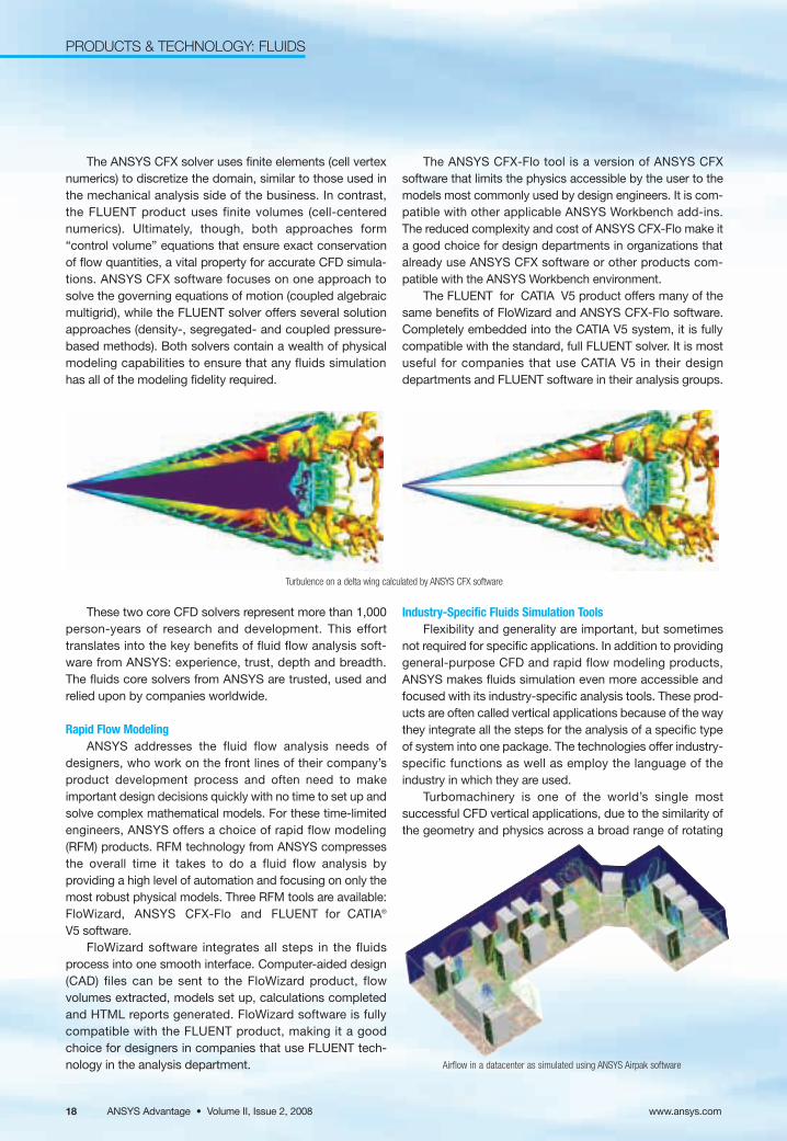
Turbulence on a delta wing calculated by ANSYS CFX software
machinery sectors. The turbosystem technology fromANSYS includes custom geometry and meshing tools aswell as special modes within the general-purpose fluidssimulation tools.
The ANSYS Icepak product is a family of applicationsfocused on electronics design and packaging. In order toimprove the performance and durability of electronic boardsand other components for optimized cooling systems, the product calculates the flow field and temperatures inelectronics and computer systems.
ANSYS POLYFLOW software is focused on the needs of the materials industry, such as polymer processing,extrusion, filmcasting and glass production. It can modelthe flow of fluids with very complex behavior, such as viscoelastic fluids. The ANSYS POLYFLOW product offersunique features such as the ability to perform reverse calculations to determine the required die shapes in extrusion. It also can calculate the final wall thickness inblow-molding and thermoforming processes.
The ANSYS Airpak product is aimed at the design ofheating, ventilation and cooling systems in buildings, suchas offices, factories, stadiums and other large publicspaces. It accurately and easily models airflow, heattransfer, contaminant transport and thermal comfort in aventilation system.
Finally, end-users can create their own vertical applica-tions within the general-purpose fluids simulation products:ANSYS CFX software offers user-configurable setup wizards and expression language; FLUENT technology provides user-defined functions; and the FloWizard tooloffers Python scripts. All of these can be used to create custom vertical applications. It is not uncommon for ananalysis department to create such vertical applications fordeployment within a design department. The main benefit ofthis approach is to ensure repeatable simulation processcontrol, and hence quality control, for any CFD process.
The extrusion of a viscoelastic food material is simulated with ANSYS POLYFLOW software. The pressure drop between the inlet and the five outlets is shown. The outletshape is computed as part of the analysis.
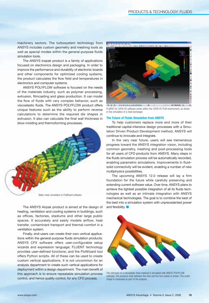
FLUENT for CATIA V5 software works within the CATIA V5 PLM environment, as shownin this simulation of a heat exchanger.
The Future of Fluids Simulation from ANSYSTo help customers replace more and more of their
traditional capital-intensive design processes with a Simu-lation Driven Product Development method, ANSYS willcontinue to innovate and integrate.
In the very near future, users will see tremendousprogress toward the ANSYS integration vision, includingcommon geometry, meshing and post-processing tools for all users of CFD products from ANSYS. Many steps inthe fluids simulation process will be automatically recorded,enabling parametric simulations. Improvements in fluid–solid connectivity will be evident, enabling a number of newmultiphysics possibilities.
The upcoming ANSYS 12.0 release will lay a firm foundation for the future while carefully preserving andextending current software value. Over time, ANSYS plans toachieve the tightest possible integration of all its fluids tech-nologies as well as an intimate integration with ANSYSmechanical technologies. The goal is to combine the best ofthe best into a simulation system with unprecedented powerand flexibility. ■
Static mixer simulation in FloWizard software
ANSYS Advantage • Volume II, Issue 2, 2008www.ansys.com 19
PRODUCTS & TECHNOLOGY: FLUIDS
PRODUCTS & TECHNOLOGY: MULTIBODY
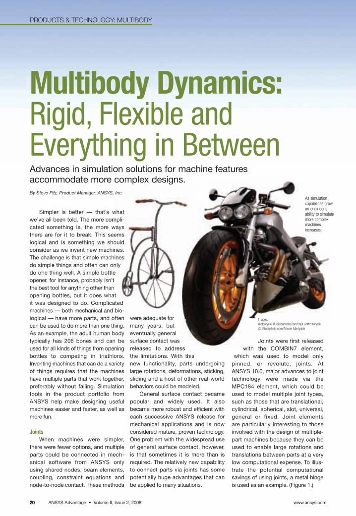
Simpler is better — that’s whatwe’ve all been told. The more compli-cated something is, the more waysthere are for it to break. This seems logical and is something we shouldconsider as we invent new machines.The challenge is that simple machinesdo simple things and often can only do one thing well. A simple bottleopener, for instance, probably isn’tthe best tool for anything other thanopening bottles, but it does what it was designed to do. Complicatedmachines — both mechanical and bio-logical — have more parts, and oftencan be used to do more than one thing.As an example, the adult human bodytypically has 206 bones and can beused for all kinds of things from openingbottles to competing in triathlons.Inventing machines that can do a varietyof things requires that the machineshave multiple parts that work together,preferably without failing. Simulationtools in the product portfolio fromANSYS help make designing usefulmachines easier and faster, as well asmore fun.
JointsWhen machines were simpler,
there were fewer options, and multipleparts could be connected in mech-anical software from ANSYS only using shared nodes, beam elements,coupling, constraint equations andnode-to-node contact. These methods
www.ansys.comANSYS Advantage • Volume II, Issue 2, 20082020
Multibody Dynamics:Rigid, Flexible andEverything in BetweenAdvances in simulation solutions for machine features accommodate more complex designs.By Steve Pilz, Product Manager, ANSYS, Inc.
Images:motorcycle © iStockphoto.com/Paul Griffin bicycle © iStockphoto.com/Artsem Martysiok
As simulationcapabilities grow,an engineer’s ability to simulatemore complexmachines increases.
Joints were first releasedwith the COMBIN7 element,
which was used to model onlypinned, or revolute, joints. AtANSYS 10.0, major advances to jointtechnology were made via theMPC184 element, which could beused to model multiple joint types,such as those that are translational,cylindrical, spherical, slot, universal,general or fixed. Joint elements are particularly interesting to thoseinvolved with the design of multiple-part machines because they can beused to enable large rotations andtranslations between parts at a verylow computational expense. To illus-trate the potential computationalsavings of using joints, a metal hingeis used as an example. (Figure 1.)
were adequate formany years, buteventually generalsurface contact wasreleased to addressthe limitations. With thisnew functionality, parts undergoinglarge rotations, deformations, sticking, sliding and a host of other real-worldbehaviors could be modeled.
General surface contact becamepopular and widely used. It alsobecame more robust and efficient witheach successive ANSYS release formechanical applications and is nowconsidered mature, proven technology.One problem with the widespread useof general surface contact, however, is that sometimes it is more than isrequired. The relatively new capabilityto connect parts via joints has somepotentially huge advantages that canbe applied to many situations.
PRODUCTS & TECHNOLOGY: MULTIBODY
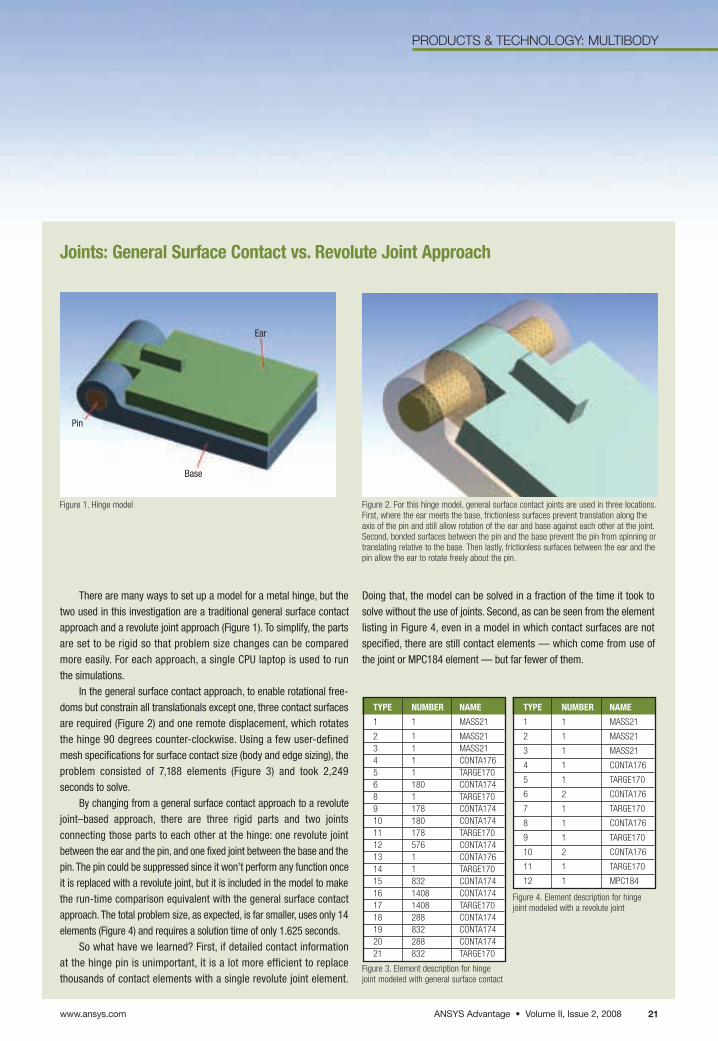
There are many ways to set up a model for a metal hinge, but thetwo used in this investigation are a traditional general surface contactapproach and a revolute joint approach (Figure 1). To simplify, the partsare set to be rigid so that problem size changes can be compared more easily. For each approach, a single CPU laptop is used to run the simulations.
In the general surface contact approach, to enable rotational free-doms but constrain all translationals except one, three contact surfacesare required (Figure 2) and one remote displacement, which rotates the hinge 90 degrees counter-clockwise. Using a few user-definedmesh specifications for surface contact size (body and edge sizing), theproblem consisted of 7,188 elements (Figure 3) and took 2,249 seconds to solve.
By changing from a general surface contact approach to a revolutejoint–based approach, there are three rigid parts and two joints connecting those parts to each other at the hinge: one revolute jointbetween the ear and the pin, and one fixed joint between the base and thepin. The pin could be suppressed since it won’t perform any function onceit is replaced with a revolute joint, but it is included in the model to makethe run-time comparison equivalent with the general surface contactapproach. The total problem size, as expected, is far smaller, uses only 14elements (Figure 4) and requires a solution time of only 1.625 seconds.
So what have we learned? First, if detailed contact information at the hinge pin is unimportant, it is a lot more efficient to replace thousands of contact elements with a single revolute joint element.
Doing that, the model can be solved in a fraction of the time it took tosolve without the use of joints. Second, as can be seen from the elementlisting in Figure 4, even in a model in which contact surfaces are notspecified, there are still contact elements — which come from use ofthe joint or MPC184 element — but far fewer of them.
TYPE NUMBER NAME
1 1 MASS21
2 1 MASS21 3 1 MASS21 4 1 CONTA176 5 1 TARGE170 6 180 CONTA174 8 1 TARGE170 9 178 CONTA174 10 180 CONTA174 11 178 TARGE170 12 576 CONTA174 13 1 CONTA176 14 1 TARGE170 15 832 CONTA174 16 1408 CONTA174 17 1408 TARGE170 18 288 CONTA174 19 832 CONTA174 20 288 CONTA174 21 832 TARGE170
TYPE NUMBER NAME
1 1 MASS21
2 1 MASS21
3 1 MASS21
4 1 CONTA176
5 1 TARGE170
6 2 CONTA176
7 1 TARGE170
8 1 CONTA176
9 1 TARGE170
10 2 CONTA176
11 1 TARGE170
12 1 MPC184
Figure 1. Hinge model Figure 2. For this hinge model, general surface contact joints are used in three locations.First, where the ear meets the base, frictionless surfaces prevent translation along the axis of the pin and still allow rotation of the ear and base against each other at the joint.Second, bonded surfaces between the pin and the base prevent the pin from spinning ortranslating relative to the base. Then lastly, frictionless surfaces between the ear and thepin allow the ear to rotate freely about the pin.
Figure 3. Element description for hingejoint modeled with general surface contact
Figure 4. Element description for hingejoint modeled with a revolute joint
ANSYS Advantage • Volume II, Issue 2, 2008www.ansys.com 21
Joints: General Surface Contact vs. Revolute Joint Approach
Pin
Base
Ear
PRODUCTS & TECHNOLOGY: MULTIBODY
ANSYS Rigid DynamicsThe ANSYS Rigid Dynamics
module, first released at Version 11.0,makes extensive use of joints for connecting parts. This is an ANSYSWorkbench add-on tool for users who have ANSYS Structural, ANSYSMechanical or ANSYS Multiphysicslicenses. The module enhances the
capability of those products by adding anexplicit solver that is tuned for solvingpurely rigid assemblies. As a result, it issignificantly faster than the implicit solverfor purely rigid transient dynamic simula-tions. The ANSYS Rigid Dynamicsmodule also has added interactive jointmanipulation and ANSYS WorkbenchSimulation interface options.
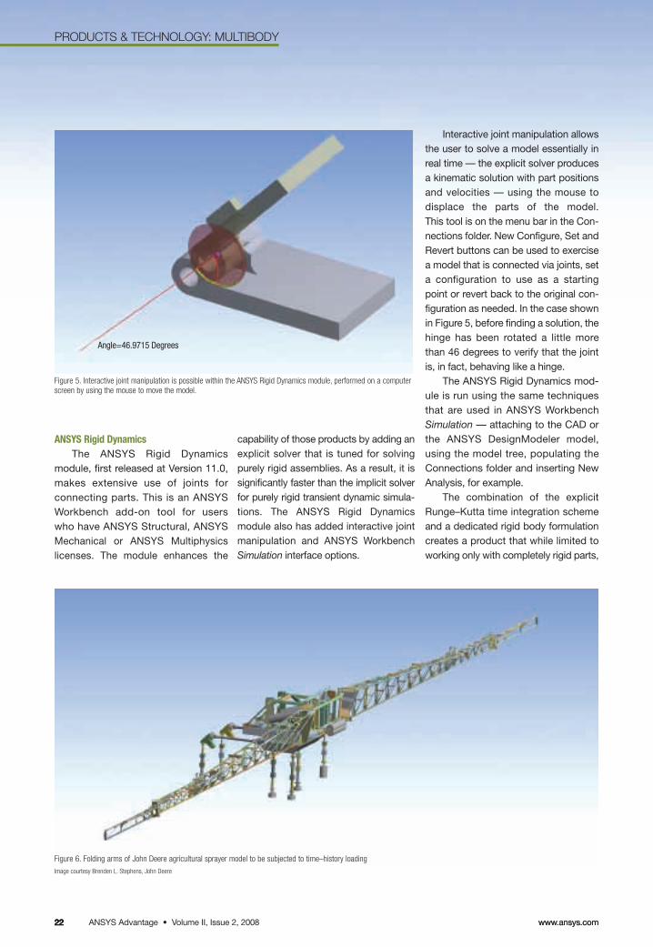
Interactive joint manipulation allowsthe user to solve a model essentially inreal time — the explicit solver producesa kinematic solution with part positionsand velocities — using the mouse todisplace the parts of the model. This tool is on the menu bar in the Con-nections folder. New Configure, Set andRevert buttons can be used to exercisea model that is connected via joints, seta configuration to use as a startingpoint or revert back to the original con-figuration as needed. In the case shownin Figure 5, before finding a solution, thehinge has been rotated a little morethan 46 degrees to verify that the jointis, in fact, behaving like a hinge.
The ANSYS Rigid Dynamics mod-ule is run using the same techniquesthat are used in ANSYS WorkbenchSimulation — attaching to the CAD orthe ANSYS DesignModeler model,using the model tree, populating theConnections folder and inserting NewAnalysis, for example.
The combination of the explicitRunge–Kutta time integration schemeand a dedicated rigid body formulationcreates a product that while limited toworking only with completely rigid parts,
Figure 5. Interactive joint manipulation is possible within the ANSYS Rigid Dynamics module, performed on a computerscreen by using the mouse to move the model.
Figure 6. Folding arms of John Deere agricultural sprayer model to be subjected to time–history loading Image courtesy Brenden L. Stephens, John Deere
www.ansys.comANSYS Advantage • Volume II, Issue 2, 20082222 www.ansys.com22
Angle=46.9715 Degrees
PRODUCTS & TECHNOLOGY: MULTIBODY
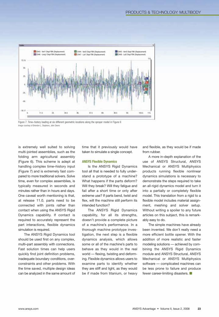
is extremely well suited to solvingmulti-jointed assemblies, such as thefolding arm agricultural assembly (Figure 6). This scheme is adept at handling complex time–history input(Figure 7) and is extremely fast com-pared to more traditional solvers. Solvetime, even for complex assemblies, istypically measured in seconds andminutes rather than in hours and days.One caveat worth mentioning is that,at release 11.0, parts need to beconnected with joints rather than contact when using the ANSYS RigidDynamics capability. If contact isrequired to accurately represent thepart interactions, flexible dynamicssimulation is required.
The ANSYS Rigid Dynamics toolshould be used first on any complex,multi–part assembly with connections.Fast solution times can help usersquickly find joint definition problems,inadequate boundary conditions, over-constraints and other problems. Withthe time saved, multiple design ideascan be analyzed in the same amount of
time that it previously would havetaken to simulate a single concept.
ANSYS Flexible DynamicsIs the ANSYS Rigid Dynamics
tool all that is needed to fully under-stand a prototype of a machine?What happens if the parts deform?Will they break? Will they fatigue andfail after a short time or only afterextreme use? If parts bend, twist andflex, will the machine still perform itsintended function?
The ANSYS Rigid Dynamicscapability, for all its strengths, doesn’t provide a complete pictureof a machine’s performance. In a thorough machine prototype inves-tigation, the next step is a flexibledynamics analysis, which allowssome or all of the machine’s parts tobehave as they would in the realworld — flexing, twisting and deform-ing. Flexible dynamics allows users toexamine parts to identify whetherthey are stiff and light, as they wouldbe if made from titanium, or heavy
and flexible, as they would be if madefrom rubber.
A more in-depth explanation of theuse of ANSYS Structural, ANSYSMechanical or ANSYS Multiphysicsproducts running flexible nonlineardynamics simulations is necessary todemonstrate the steps required to takean all-rigid dynamics model and turn itinto a partially or completely flexiblemodel. This translation from a rigid to aflexible model includes material assign-ment, meshing and solver setup.Without writing a spoiler to any futurearticles on this subject, this is remark-ably easy to do.
The simple machines have alreadybeen invented. We don’t really need amore efficient bottle opener. With theaddition of more realistic and fastermodeling solutions — achieved by com-bining the ANSYS Rigid Dynamicsmodule and ANSYS Structural, ANSYSMechanical or ANSYS Multiphysics software — complicated machines canbe less prone to failure and producefewer career-limiting disasters. ■
Figure 7. Time–history loading at six different geometric locations along the sprayer model in Figure 6Image courtesy of Brenden L. Stephens, John Deere
ANSYS Advantage • Volume II, Issue 2, 2008www.ansys.com 23
CH43 - Vert1 Displ FBK (Displacement)CH46 - Long1 Displ FBK (Displacement)
73.15
50.
25.
0.
-25.
-50.
-78.17
CH44 - Vert2 Displ FBK (Displacement)CH47 - Lat1 Displ FBK (Displacement)
CH45 - Vert3 Displ FBK (Displacement)CH48 - Lat2 Displ FBK (Displacement)
0. 11.5 23. 34.5 46. 57.5 69. 80.5 92. 103.5 115.
115.
www.ansys.comANSYS Advantage • Volume II, Issue 2, 200824
PRODUCTS & TECHNOLOGY: NONLINEAR
24
In today’s competitive environment in which everyonestrives to develop the best design with the best perform-ance, durability and reliability, it is unrealistic to rely on linearanalysis alone. Analyses must be scaled from single partsand simplified assembly-level models to complete system-level models that involve multiple complex subassemblies.As more parts get added to a simulation model, it becomesmore difficult to ignore the nonlinear aspects of the physics,and, at the same time, expect realistic answers.
In some situations involving single- or multiple-part models, analysis with linear assumptions can be sufficient.However, for every assumption made, there is some sacrifice in the accuracy of the simulation. Ignoring nonlinear-ities in a model might lead to overly conservative or weakdesign in certain situations, or might result in the omission ofunexpected but valuable information about the design or per-formance of the model. It is essential to understand when andwhen not to account for nonlinearities. The following are some situations in which non-linearities are commonly encountered.
ContactCurrently, auto-contact detection
in ANSYS Workbench Simulationallows users to quickly set up con-tact (part interactions) betweenmultiple entity types (solids, sheets,beams). However, in cases in whichtwo parts interact with each other, theparts might stick or slide againsteach other instead of remainingstatic. Also, their stiffness mightchange depending upon whetherthey touch each other or not, as is seen with interference or snap-fit cases. Ignoring sliding may beacceptable for a large class of problems,
but for those with moving parts orthat involve friction, it is unwise tomake this assumption.
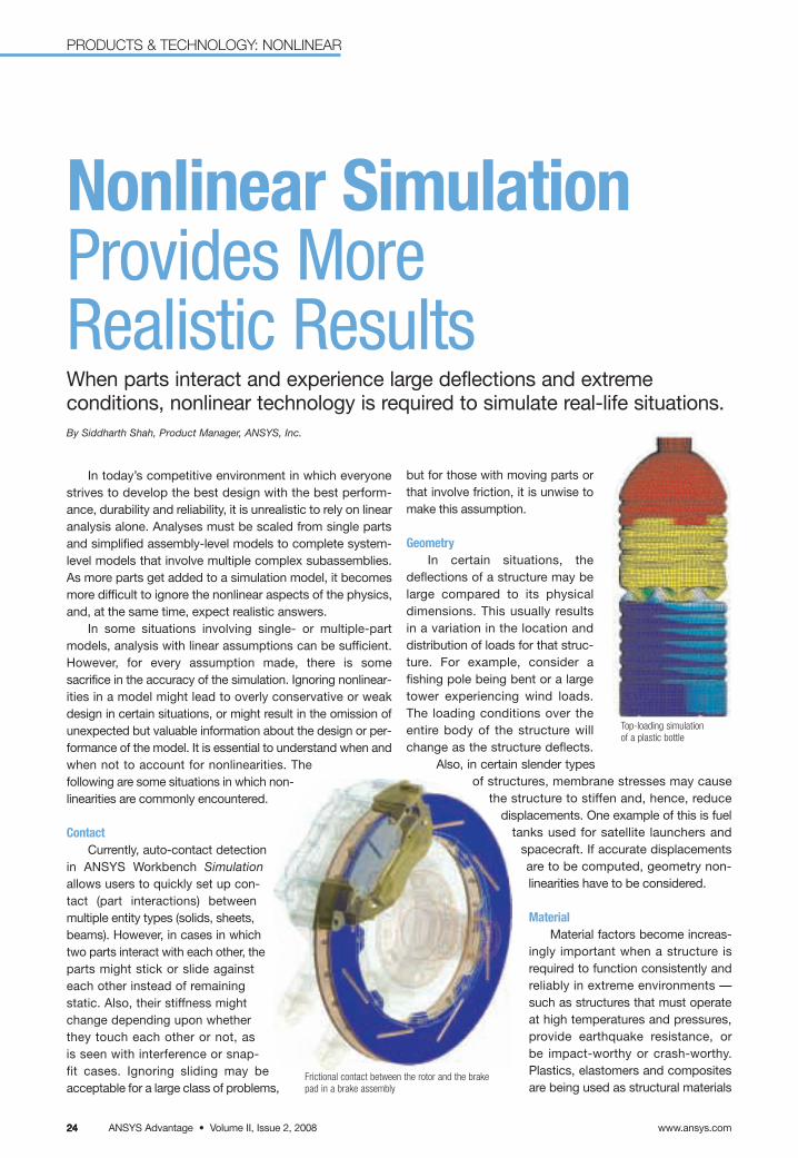
GeometryIn certain situations, the
deflections of a structure may belarge compared to its physicaldimensions. This usually results in a variation in the location and distribution of loads for that struc-ture. For example, consider afishing pole being bent or a largetower experiencing wind loads.The loading conditions over theentire body of the structure willchange as the structure deflects.
Also, in certain slender typesof structures, membrane stresses may cause
the structure to stiffen and, hence, reducedisplacements. One example of this is fuel
tanks used for satellite launchers andspacecraft. If accurate displacementsare to be computed, geometry non-linearities have to be considered.
MaterialMaterial factors become increas-
ingly important when a structure isrequired to function consistently andreliably in extreme environments —such as structures that must operateat high temperatures and pressures,provide earthquake resistance, or be impact-worthy or crash-worthy.Plastics, elastomers and compositesare being used as structural materials
Nonlinear SimulationProvides More Realistic ResultsWhen parts interact and experience large deflections and extreme conditions, nonlinear technology is required to simulate real-life situations.By Siddharth Shah, Product Manager, ANSYS, Inc.
Top-loading simulationof a plastic bottle
Frictional contact between the rotor and the brakepad in a brake assembly
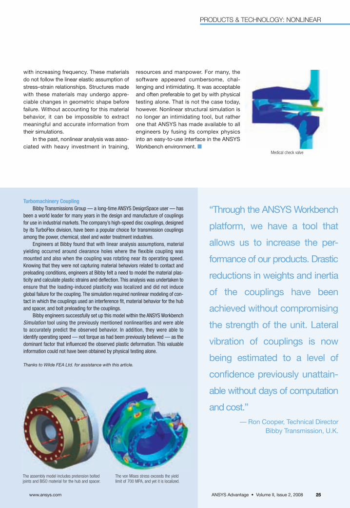
resources and manpower. For many, thesoftware appeared cumbersome, chal-lenging and intimidating. It was acceptableand often preferable to get by with physical testing alone. That is not the case today,however. Nonlinear structural simulation isno longer an intimidating tool, but rather one that ANSYS has made available to allengineers by fusing its complex physicsinto an easy-to-use interface in the ANSYSWorkbench environment. ■
with increasing frequency. These materialsdo not follow the linear elastic assumption ofstress–strain relationships. Structures madewith these materials may undergo appre-ciable changes in geometric shape beforefailure. Without accounting for this materialbehavior, it can be impossible to extractmeaningful and accurate information fromtheir simulations.
In the past, nonlinear analysis was asso-ciated with heavy investment in training,
Medical check valve
ANSYS Advantage • Volume II, Issue 2, 2008www.ansys.com 25
“Through the ANSYS Workbench
platform, we have a tool that
allows us to increase the per-
formance of our products. Drastic
reductions in weights and inertia
of the couplings have been
achieved without compromising
the strength of the unit. Lateral
vibration of couplings is now
being estimated to a level of
confidence previously unattain-
able without days of computation
and cost.”— Ron Cooper, Technical Director
Bibby Transmission, U.K.
Turbomachinery Coupling Bibby Transmissions Group — a long-time ANSYS DesignSpace user — has
been a world leader for many years in the design and manufacture of couplingsfor use in industrial markets. The company’s high-speed disc couplings, designedby its TurboFlex division, have been a popular choice for transmission couplingsamong the power, chemical, steel and water treatment industries.
Engineers at Bibby found that with linear analysis assumptions, materialyielding occurred around clearance holes where the flexible coupling was mounted and also when the coupling was rotating near its operating speed.Knowing that they were not capturing material behaviors related to contact andpreloading conditions, engineers at Bibby felt a need to model the material plas-ticity and calculate plastic strains and deflection. This analysis was undertaken toensure that the loading-induced plasticity was localized and did not induce global failure for the coupling. The simulation required nonlinear modeling of con-tact in which the couplings used an interference fit, material behavior for the huband spacer, and bolt preloading for the couplings.
Bibby engineers successfully set up this model within the ANSYS WorkbenchSimulation tool using the previously mentioned nonlinearities and were able to accurately predict the observed behavior. In addition, they were able to identify operating speed — not torque as had been previously believed — as the dominant factor that influenced the observed plastic deformation. This valuableinformation could not have been obtained by physical testing alone.
Thanks to Wilde FEA Ltd. for assistance with this article.
The assembly model includes pretension boltedjoints and BISO material for the hub and spacer.
The von Mises stress exceeds the yieldlimit of 700 MPA, and yet it is localized.
PRODUCTS & TECHNOLOGY: NONLINEAR
25
www.ansys.comANSYS Advantage • Volume II, Issue 2, 200826
CHEMICAL PROCESSINGPRODUCTS & TECHNOLOGY: MULTIPHYSICS
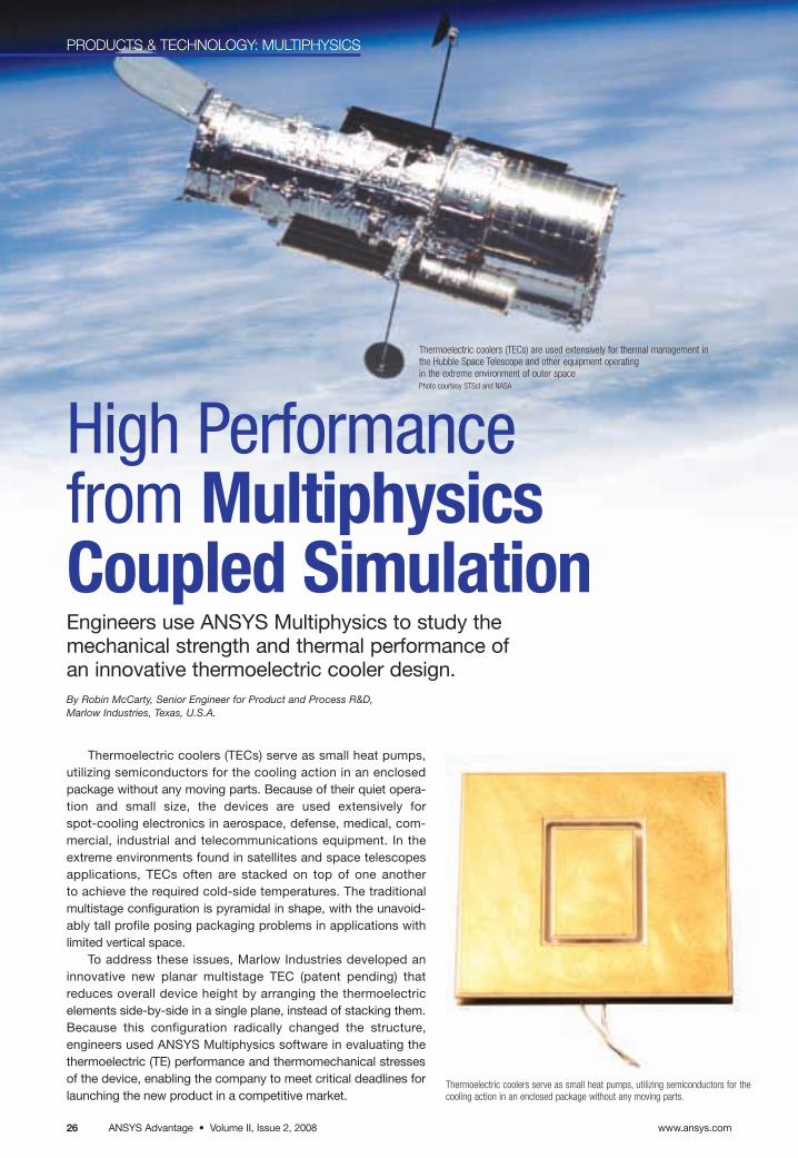
Thermoelectric coolers (TECs) serve as small heat pumps, utilizing semiconductors for the cooling action in an enclosedpackage without any moving parts. Because of their quiet opera-tion and small size, the devices are used extensively forspot-cooling electronics in aerospace, defense, medical, com-mercial, industrial and telecommunications equipment. In theextreme environments found in satellites and space telescopesapplications, TECs often are stacked on top of one another to achieve the required cold-side temperatures. The traditional multistage configuration is pyramidal in shape, with the unavoid-ably tall profile posing packaging problems in applications withlimited vertical space.
To address these issues, Marlow Industries developed aninnovative new planar multistage TEC (patent pending) thatreduces overall device height by arranging the thermoelectric elements side-by-side in a single plane, instead of stacking them.Because this configuration radically changed the structure, engineers used ANSYS Multiphysics software in evaluating thethermoelectric (TE) performance and thermomechanical stressesof the device, enabling the company to meet critical deadlines forlaunching the new product in a competitive market.
High Performance from MultiphysicsCoupled SimulationEngineers use ANSYS Multiphysics to study the mechanical strength and thermal performance of an innovative thermoelectric cooler design.By Robin McCarty, Senior Engineer for Product and Process R&D, Marlow Industries, Texas, U.S.A.
Thermoelectric coolers (TECs) are used extensively for thermal management inthe Hubble Space Telescope and other equipment operating in the extreme environment of outer spacePhoto courtesy STScI and NASA
Thermoelectric coolers serve as small heat pumps, utilizing semiconductors for thecooling action in an enclosed package without any moving parts.
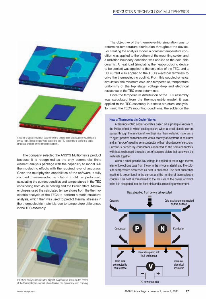
ANSYS Advantage • Volume II, Issue 2, 2008www.ansys.com 27
PRODUCTS & TECHNOLOGY: MULTIPHYSICS
The company selected the ANSYS Multiphysics productbecause it is recognized as the only commercial finite element analysis package with the capability to model 3-Dthermoelectric effects with the required level of accuracy.Given the multiphysics capabilities of the software, a fullycoupled thermoelectric simulation could be performed, calculating the current densities and temperatures in the TECconsidering both Joule heating and the Peltier effect. Marlowengineers used the calculated temperatures from the thermo-electric analysis of the TECs to perform a static structuralanalysis, which then was used to predict thermal stresses inthe thermoelectric materials due to temperature differencesin the TEC assembly.
Structural analysis indicates the highest magnitude of stress on the cornerof the thermoelectric element where Marlow has historically seen cracking.
The objective of the thermoelectric simulation was todetermine temperature distribution throughout the device.For creating the analysis model, a constant temperature con-dition was applied to the bottom of the mounting solder, anda radiation boundary condition was applied to the cold-sideceramic. A heat load (simulating the heat-producing deviceto be cooled) was applied to the cold side of the TEC, and aDC current was applied to the TEC’s electrical terminals todrive the thermoelectric cooling. From this coupled-physicssimulation, the minimum cold-side temperature, temperatureuniformity of the top stage, voltage drop and electrical resistance of the TEC were determined.
Once the temperature distribution of the TEC assemblywas calculated from the thermoelectric model, it wasapplied to the TEC assembly in a static structural analysis.To mimic the TEC’s mounting conditions, the solder on the
How a Thermoelectric Cooler WorksA thermoelectric cooler operates based on a principle known as
the Peltier effect, in which cooling occurs when a small electric currentpasses through the junction of two dissimilar thermoelectric materials: a“p-type” positive semiconductor with a scarcity of electrons in its atomsand an “n-type” negative semiconductor with an abundance of electrons.Current is carried by conductors connected to the semiconductors,with heat exchanged through a set of ceramic plates that sandwich thematerials together.
When a small positive DC voltage is applied to the n-type thermoelement, electrons pass from the p- to the n-type material, and the cold-side temperature decreases as heat is absorbed. The heat absorption(cooling) is proportional to the current and the number of thermoelectriccouples. This heat is transferred to the hot side of the cooler, at whichpoint it is dissipated into the heat sink and surrounding environment.
P N
- +V
Heat absorbed from device being cooled
Heat dissipated into hot exchanger
DC power source
Heat sinkconnected tothis surface
Ceramicelectricalinsulator
Cold exchanger connectedto this surface
Ceramic
Conductor Conductor
Coupled-physics simulation determined the temperature distribution throughout thedevice (top). These results were applied to the TEC assembly to perform a static structural analysis of the structure (bottom).
www.ansys.comANSYS Advantage • Volume II, Issue 2, 200828
PRODUCTS & TECHNOLOGY: MULTIPHYSICS
hot side of the device was fixed on the bottom surface.Maximum principal stress was used to evaluate and com-pare the TEC designs because it can be directly related tothe failure of a brittle material, such as bismuth telluride.
The testing team identified the thermoelectric elementwith the maximum stress and then refined the finite elementmesh in that area to ensure that stress convergence hadbeen obtained for the structural simulation. Using a plot of maximum principal stress distribution in a typical TE element, the engineering team found that the maximumstress occurs on the corner of the TE element, which correlated to where Marlow historically had seen cracking in thermoelectric elements that resulted in device failure.
To validate the new planar multistage designs, Marlow evaluated the mechanical stress levels for a thermoelectrically
equivalent traditional multistage device and a planar multistagedevice. Each device consisted of three stages equivalent withthermoelectric element dimensions and thermoelectric elementcount per stage. In the model, three different currents were eval-uated, and the maximum principal stress located in the mosthighly stressed thermoelectric element was noted.
Through these analyses, Marlow configured planardesigns with maximum principal stress levels comparable tothe traditional multistage devices. Thermal performance also was nearly equivalent. The correlation between the stress results for the traditional multistage and planar multi-stage devices provided confidence in the new planarmultistage design concepts. This type of evaluation would not have been possible without the multiphysics simulationcapabilities available in software from ANSYS. ■
In contrast to traditional multistage thermoelectric coolers with elements stacked in a pyramid shape (left), the new Marlow flat configuration (right, patent pending) arranges stagesside by side. The new design reduces the height of the device and also changes heat flow through the ceramic material (denoted by the purple arrow).
Package base
Heat-producing device
Package base
Traditional multistage design New planar multistage design
Cold ceramic
Cold ceramic
Solder
SolderHeat-producing device
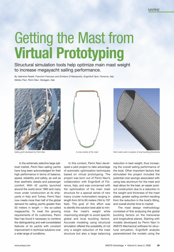
ANSYS Advantage • Volume II, Issue 2, 2008
MARINE
www.ansys.com 29
In the extremely selective large sail-boat market, Perini Navi sailing yachtshave long been acknowledged for theirhigh performance in terms of balance,speed, reliability and safety, as well astheir aesthetic details and passengercomfort. With 42 yachts launchedaround the world since 1983 and manymore under construction at its ship-yards in Italy and Turkey, Perini Navinow meets more than half of the globaldemand for sailing yachts greater than50 meters in length — the so-calledmegayachts. To meet the growingrequirements of its customers, PeriniNavi has found it necessary to combinethe distinguishing and well-consolidatedfeatures of its yachts with constantimprovement in technical solutions overa wide range of conditions.
In this context, Perini Navi devel-oped a pilot project to take advantageof automatic optimization techniquesbased on virtual prototyping. Theproject was born out of Perini Navi’scollaboration with EnginSoft of Flo-rence, Italy, and was concerned withthe optimization of the main maststructure for a special series of newheavy cruiser motorsailers ranging inlength from 50 to 60 meters (164 to 197feet). The goal of this effort was to identify the solution best able to min-imize the mast’s weight while maximizing strength to avoid specificglobal and local buckling factors.Accurate modeling using structuralsimulation offered the possibility of notonly a weight reduction of the maststructure but also a large balancing
reduction in keel weight, thus increas-ing the overall sailing performance ofthe boat. Other important factors thatstimulated the project included thepotential cost savings associated withusing less aluminum for the mast andlead alloys for the keel, an easier prod-uct construction due to a reduction inthe weight and thickness of the mastplates, greater sailing comfort resultingfrom the reduction in the boat’s tilting,and overall shorter time to market.
The mast design methodologyconsisted of first analyzing the globalbuckling factors on the transverse and longitudinal planes. Starting withmodels developed by Perini Navi inANSYS Mechanical software for struc-tural simulation, EnginSoft analystsparameterized the models using the
Getting the Mast fromVirtual PrototypingStructural simulation tools help optimize main mast weight to increase megayacht sailing performance.By Valentina Peselli, Franchini Franceso and Emiliano D’Alessandro, EnginSoft SpA, Florence, Italy
Matteo Paci, Perini Navi, Viareggio, Italy
Sailing yacht developed by Perini Navi A cross section of the mast Shell model used in analysis of local buckling phenomena
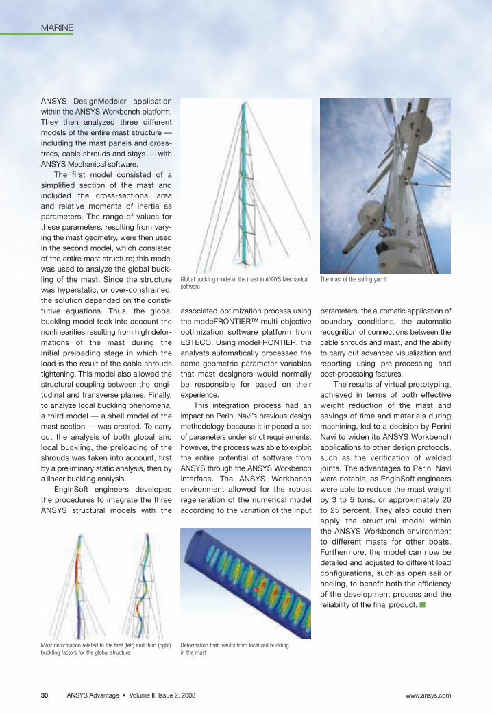
www.ansys.comANSYS Advantage • Volume II, Issue 2, 200830
MARINE
ANSYS DesignModeler applicationwithin the ANSYS Workbench platform.They then analyzed three different models of the entire mast structure —including the mast panels and cross-trees, cable shrouds and stays — withANSYS Mechanical software.
The first model consisted of a simplified section of the mast andincluded the cross-sectional area and relative moments of inertia asparameters. The range of values forthese parameters, resulting from vary-ing the mast geometry, were then usedin the second model, which consistedof the entire mast structure; this modelwas used to analyze the global buck-ling of the mast. Since the structurewas hyperstatic, or over-constrained,the solution depended on the consti-tutive equations. Thus, the globalbuckling model took into account thenonlinearities resulting from high defor-mations of the mast during the initial preloading stage in which theload is the result of the cable shroudstightening. This model also allowed thestructural coupling between the longi-tudinal and transverse planes. Finally,to analyze local buckling phenomena, a third model — a shell model of themast section — was created. To carryout the analysis of both global and local buckling, the preloading of theshrouds was taken into account, firstby a preliminary static analysis, then bya linear buckling analysis.
EnginSoft engineers developed the procedures to integrate the three ANSYS structural models with the
associated optimization process usingthe modeFRONTIER™ multi-objective optimization software platform fromESTECO. Using modeFRONTIER, theanalysts automatically processed thesame geometric parameter variablesthat mast designers would normally be responsible for based on their experience.
This integration process had animpact on Perini Navi’s previous designmethodology because it imposed a setof parameters under strict requirements;however, the process was able to exploitthe entire potential of software fromANSYS through the ANSYS Workbenchinterface. The ANSYS Workbench environment allowed for the robustregeneration of the numerical modelaccording to the variation of the input
parameters, the automatic application ofboundary conditions, the automaticrecognition of connections between thecable shrouds and mast, and the abilityto carry out advanced visualization andreporting using pre-processing andpost-processing features.
The results of virtual prototyping,achieved in terms of both effectiveweight reduction of the mast and savings of time and materials duringmachining, led to a decision by PeriniNavi to widen its ANSYS Workbenchapplications to other design protocols,such as the verification of weldedjoints. The advantages to Perini Naviwere notable, as EnginSoft engineerswere able to reduce the mast weightby 3 to 5 tons, or approximately 20 to 25 percent. They also could thenapply the structural model within the ANSYS Workbench environment to different masts for other boats. Furthermore, the model can now bedetailed and adjusted to different loadconfigurations, such as open sail orheeling, to benefit both the efficiencyof the development process and the reliability of the final product. ■
The mast of the sailing yachtGlobal buckling model of the mast in ANSYS Mechanicalsoftware
Mast deformation related to the first (left) and third (right)buckling factors for the global structure
Deformation that results from localized bucklingin the mast
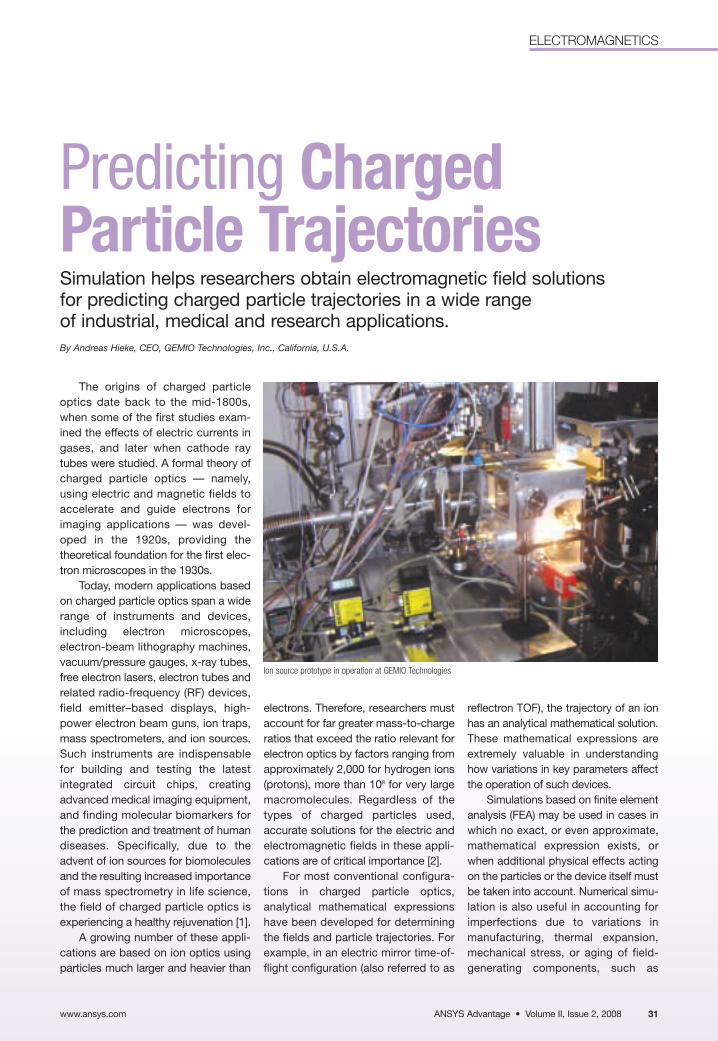
ANSYS Advantage • Volume II, Issue 2, 2008www.ansys.com 31
ELECTROMAGNETICS
Predicting Charged Particle TrajectoriesSimulation helps researchers obtain electromagnetic field solutions for predicting charged particle trajectories in a wide range of industrial, medical and research applications.By Andreas Hieke, CEO, GEMIO Technologies, Inc., California, U.S.A.
The origins of charged particleoptics date back to the mid-1800s,when some of the first studies exam-ined the effects of electric currents ingases, and later when cathode raytubes were studied. A formal theory ofcharged particle optics — namely,using electric and magnetic fields toaccelerate and guide electrons forimaging applications — was devel-oped in the 1920s, providing thetheoretical foundation for the first elec-tron microscopes in the 1930s.
Today, modern applications basedon charged particle optics span a widerange of instruments and devices,including electron microscopes, electron-beam lithography machines,vacuum/pressure gauges, x-ray tubes,free electron lasers, electron tubes andrelated radio-frequency (RF) devices,field emitter–based displays, high-power electron beam guns, ion traps,mass spectrometers, and ion sources.Such instruments are indispensable for building and testing the latest integrated circuit chips, creatingadvanced medical imaging equipment,and finding molecular biomarkers forthe prediction and treatment of humandiseases. Specifically, due to theadvent of ion sources for biomoleculesand the resulting increased importanceof mass spectrometry in life science,the field of charged particle optics isexperiencing a healthy rejuvenation [1].
A growing number of these appli-cations are based on ion optics usingparticles much larger and heavier than
electrons. Therefore, researchers mustaccount for far greater mass-to-chargeratios that exceed the ratio relevant forelectron optics by factors ranging fromapproximately 2,000 for hydrogen ions(protons), more than 108 for very largemacromolecules. Regardless of thetypes of charged particles used, accurate solutions for the electric andelectromagnetic fields in these appli-cations are of critical importance [2].
For most conventional configura-tions in charged particle optics,analytical mathematical expressionshave been developed for determiningthe fields and particle trajectories. Forexample, in an electric mirror time-of-flight configuration (also referred to as
reflectron TOF), the trajectory of an ionhas an analytical mathematical solution.These mathematical expressions areextremely valuable in understandinghow variations in key parameters affectthe operation of such devices.
Simulations based on finite elementanalysis (FEA) may be used in cases inwhich no exact, or even approximate,mathematical expression exists, orwhen additional physical effects actingon the particles or the device itself mustbe taken into account. Numerical simu-lation is also useful in accounting forimperfections due to variations in manufacturing, thermal expansion,mechanical stress, or aging of field-generating components, such as
Ion source prototype in operation at GEMIO Technologies
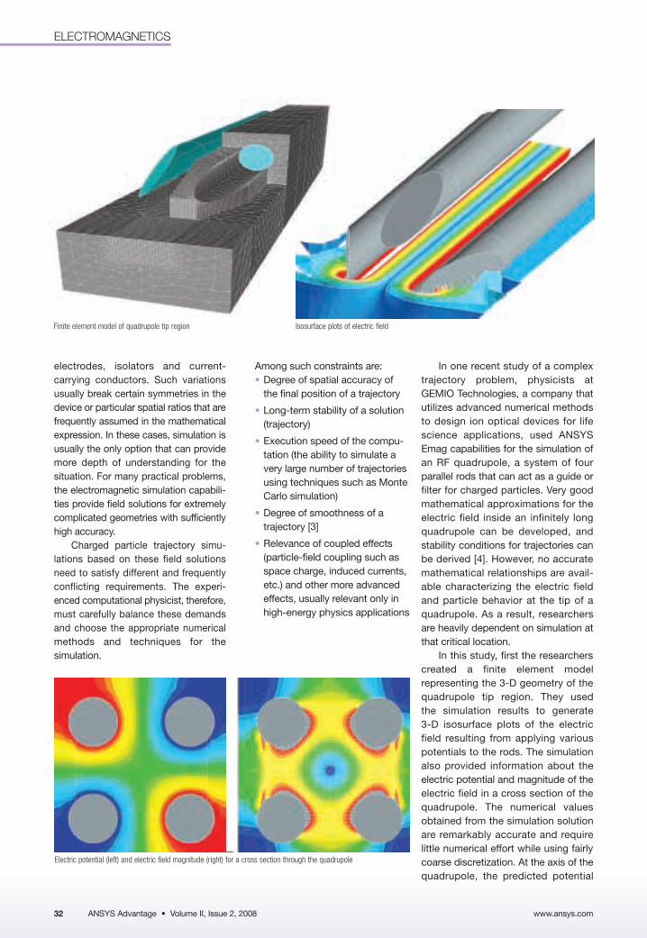
www.ansys.com32
ELECTROMAGNETICS
electrodes, isolators and current-carrying conductors. Such variationsusually break certain symmetries in thedevice or particular spatial ratios that arefrequently assumed in the mathematicalexpression. In these cases, simulation isusually the only option that can providemore depth of understanding for the situation. For many practical problems,the electromagnetic simulation capabili-ties provide field solutions for extremelycomplicated geometries with sufficientlyhigh accuracy.
Charged particle trajectory simu-lations based on these field solutionsneed to satisfy different and frequentlyconflicting requirements. The experi-enced computational physicist, therefore,must carefully balance these demandsand choose the appropriate numericalmethods and techniques for the simulation.
In one recent study of a complextrajectory problem, physicists atGEMIO Technologies, a company that utilizes advanced numerical methodsto design ion optical devices for lifescience applications, used ANSYSEmag capabilities for the simulation ofan RF quadrupole, a system of fourparallel rods that can act as a guide orfilter for charged particles. Very goodmathematical approximations for theelectric field inside an infinitely longquadrupole can be developed, andstability conditions for trajectories canbe derived [4]. However, no accuratemathematical relationships are avail-able characterizing the electric fieldand particle behavior at the tip of aquadrupole. As a result, researchersare heavily dependent on simulation atthat critical location.
In this study, first the researcherscreated a finite element model representing the 3-D geometry of thequadrupole tip region. They used the simulation results to generate 3-D isosurface plots of the electric field resulting from applying various potentials to the rods. The simulationalso provided information about theelectric potential and magnitude of theelectric field in a cross section of thequadrupole. The numerical valuesobtained from the simulation solutionare remarkably accurate and require little numerical effort while using fairlycoarse discretization. At the axis of thequadrupole, the predicted potential
Finite element model of quadrupole tip region Isosurface plots of electric field
Among such constraints are: • Degree of spatial accuracy of
the final position of a trajectory
• Long-term stability of a solution(trajectory)
• Execution speed of the compu-tation (the ability to simulate avery large number of trajectoriesusing techniques such as MonteCarlo simulation)
• Degree of smoothness of a trajectory [3]
• Relevance of coupled effects(particle-field coupling such asspace charge, induced currents,etc.) and other more advancedeffects, usually relevant only inhigh-energy physics applications
ANSYS Advantage • Volume II, Issue 2, 2008
Electric potential (left) and electric field magnitude (right) for a cross section through the quadrupole
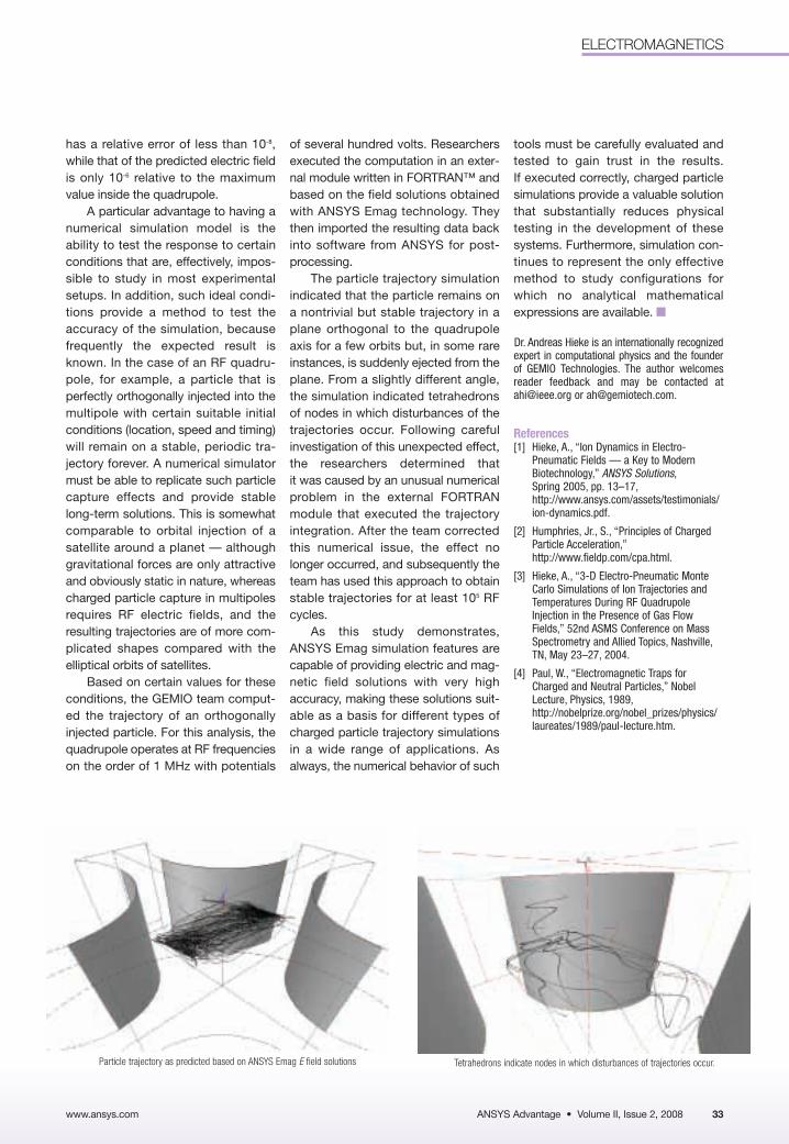
ANSYS Advantage • Volume II, Issue 2, 2008
ELECTROMAGNETICS
www.ansys.com 33
has a relative error of less than 10-8,while that of the predicted electric fieldis only 10-6 relative to the maximumvalue inside the quadrupole.
A particular advantage to having anumerical simulation model is the ability to test the response to certainconditions that are, effectively, impos-sible to study in most experimentalsetups. In addition, such ideal condi-tions provide a method to test theaccuracy of the simulation, becausefrequently the expected result isknown. In the case of an RF quadru-pole, for example, a particle that isperfectly orthogonally injected into themultipole with certain suitable initialconditions (location, speed and timing)will remain on a stable, periodic tra-jectory forever. A numerical simulatormust be able to replicate such particlecapture effects and provide stablelong-term solutions. This is somewhatcomparable to orbital injection of asatellite around a planet — althoughgravitational forces are only attractiveand obviously static in nature, whereascharged particle capture in multipolesrequires RF electric fields, and theresulting trajectories are of more com-plicated shapes compared with theelliptical orbits of satellites.
Based on certain values for theseconditions, the GEMIO team comput-ed the trajectory of an orthogonallyinjected particle. For this analysis, thequadrupole operates at RF frequencieson the order of 1 MHz with potentials
of several hundred volts. Researchersexecuted the computation in an exter-nal module written in FORTRAN™ andbased on the field solutions obtainedwith ANSYS Emag technology. Theythen imported the resulting data backinto software from ANSYS for post-processing.
The particle trajectory simulationindicated that the particle remains on a nontrivial but stable trajectory in aplane orthogonal to the quadrupoleaxis for a few orbits but, in some rareinstances, is suddenly ejected from theplane. From a slightly different angle,the simulation indicated tetrahedronsof nodes in which disturbances of the trajectories occur. Following carefulinvestigation of this unexpected effect,the researchers determined that it was caused by an unusual numericalproblem in the external FORTRANmodule that executed the trajectoryintegration. After the team correctedthis numerical issue, the effect nolonger occurred, and subsequently theteam has used this approach to obtainstable trajectories for at least 105 RFcycles.
As this study demonstrates,ANSYS Emag simulation features arecapable of providing electric and mag-netic field solutions with very highaccuracy, making these solutions suit-able as a basis for different types ofcharged particle trajectory simulationsin a wide range of applications. Asalways, the numerical behavior of such
Particle trajectory as predicted based on ANSYS Emag E field solutions Tetrahedrons indicate nodes in which disturbances of trajectories occur.
tools must be carefully evaluated andtested to gain trust in the results. If executed correctly, charged particlesimulations provide a valuable solutionthat substantially reduces physical testing in the development of thesesystems. Furthermore, simulation con-tinues to represent the only effectivemethod to study configurations forwhich no analytical mathematicalexpressions are available. ■
Dr. Andreas Hieke is an internationally recognizedexpert in computational physics and the founderof GEMIO Technologies. The author welcomes reader feedback and may be contacted [email protected] or [email protected].
References[1] Hieke, A., “Ion Dynamics in Electro-
Pneumatic Fields — a Key to ModernBiotechnology,” ANSYS Solutions,Spring 2005, pp. 13–17,http://www.ansys.com/assets/testimonials/ion-dynamics.pdf.
[2] Humphries, Jr., S., “Principles of ChargedParticle Acceleration,”http://www.fieldp.com/cpa.html.
[3] Hieke, A., “3-D Electro-Pneumatic MonteCarlo Simulations of Ion Trajectories andTemperatures During RF QuadrupoleInjection in the Presence of Gas FlowFields,” 52nd ASMS Conference on MassSpectrometry and Allied Topics, Nashville,TN, May 23–27, 2004.
[4] Paul, W., “Electromagnetic Traps forCharged and Neutral Particles,” NobelLecture, Physics, 1989,http://nobelprize.org/nobel_prizes/physics/laureates/1989/paul-lecture.htm.
www.ansys.comANSYS Advantage • Volume II, Issue 2, 200834
CHEMICAL PROCESSING
34
ROTATING MACHINERY: TURBINE RUNNER
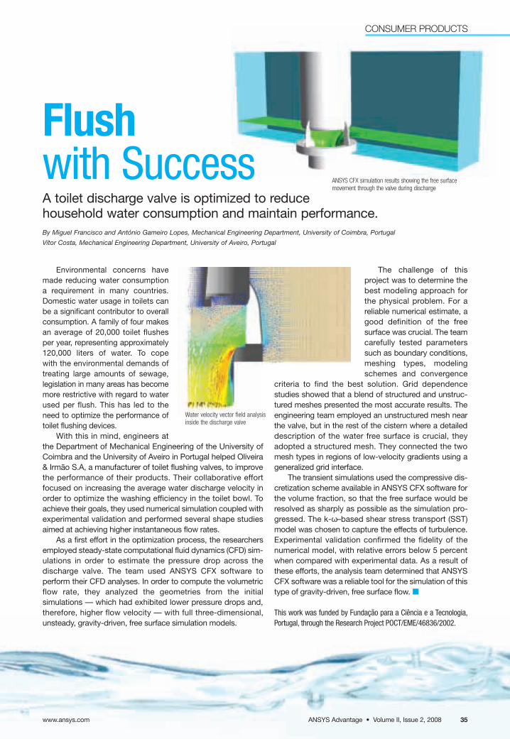
Environmental concerns havemade reducing water consumption a requirement in many countries.Domestic water usage in toilets canbe a significant contributor to overallconsumption. A family of four makesan average of 20,000 toilet flushes per year, representing approximately120,000 liters of water. To cope with the environmental demands of treating large amounts of sewage,legislation in many areas has becomemore restrictive with regard to waterused per flush. This has led to theneed to optimize the performance oftoilet flushing devices.
With this in mind, engineers atthe Department of Mechanical Engineering of the University ofCoimbra and the University of Aveiro in Portugal helped Oliveira& Irmão S.A, a manufacturer of toilet flushing valves, to improvethe performance of their products. Their collaborative effortfocused on increasing the average water discharge velocity inorder to optimize the washing efficiency in the toilet bowl. Toachieve their goals, they used numerical simulation coupled withexperimental validation and performed several shape studiesaimed at achieving higher instantaneous flow rates.
As a first effort in the optimization process, the researchersemployed steady-state computational fluid dynamics (CFD) sim-ulations in order to estimate the pressure drop across thedischarge valve. The team used ANSYS CFX software to perform their CFD analyses. In order to compute the volumetricflow rate, they analyzed the geometries from the initial simulations — which had exhibited lower pressure drops and,therefore, higher flow velocity — with full three-dimensional,unsteady, gravity-driven, free surface simulation models.
The challenge of this project was to determine thebest modeling approach forthe physical problem. For areliable numerical estimate, agood definition of the free surface was crucial. The teamcarefully tested parameterssuch as boundary conditions,meshing types, modelingschemes and convergence
criteria to find the best solution. Grid dependence studies showed that a blend of structured and unstruc-tured meshes presented the most accurate results. The engineering team employed an unstructured mesh nearthe valve, but in the rest of the cistern where a detaileddescription of the water free surface is crucial, theyadopted a structured mesh. They connected the twomesh types in regions of low-velocity gradients using ageneralized grid interface.
The transient simulations used the compressive dis-cretization scheme available in ANSYS CFX software forthe volume fraction, so that the free surface would beresolved as sharply as possible as the simulation pro-gressed. The k-ω–based shear stress transport (SST)model was chosen to capture the effects of turbulence.Experimental validation confirmed the fidelity of thenumerical model, with relative errors below 5 percentwhen compared with experimental data. As a result ofthese efforts, the analysis team determined that ANSYSCFX software was a reliable tool for the simulation of thistype of gravity-driven, free surface flow. ■
This work was funded by Fundação para a Ciência e a Tecnologia,Portugal, through the Research Project POCT/EME/46836/2002.
Flushwith SuccessA toilet discharge valve is optimized to reduce household water consumption and maintain performance.By Miguel Francisco and António Gameiro Lopes, Mechanical Engineering Department, University of Coimbra, Portugal
Vítor Costa, Mechanical Engineering Department, University of Aveiro, Portugal
ANSYS CFX simulation results showing the free surfacemovement through the valve during discharge
Water velocity vector field analysisinside the discharge valve
ANSYS Advantage • Volume II, Issue 2, 2008
CONSUMER PRODUCTS
www.ansys.com 35
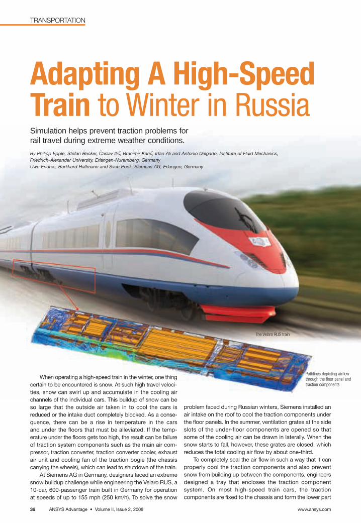
Adapting A High-SpeedTrain to Winter in RussiaSimulation helps prevent traction problems for rail travel during extreme weather conditions.
By Philipp Epple, Stefan Becker, Caslav Ilic, Branimir Karic, Irfan Ali and Antonio Delgado, Institute of Fluid Mechanics, Friedrich-Alexander University, Erlangen-Nuremberg, Germany Uwe Endres, Burkhard Halfmann and Sven Pook, Siemens AG, Erlangen, Germany
When operating a high-speed train in the winter, one thingcertain to be encountered is snow. At such high travel veloci-ties, snow can swirl up and accumulate in the cooling airchannels of the individual cars. This buildup of snow can beso large that the outside air taken in to cool the cars isreduced or the intake duct completely blocked. As a conse-quence, there can be a rise in temperature in the cars and under the floors that must be alleviated. If the temp-erature under the floors gets too high, the result can be failureof traction system components such as the main air com-pressor, traction converter, traction converter cooler, exhaust air unit and cooling fan of the traction bogie (the chassis carrying the wheels), which can lead to shutdown of the train.
At Siemens AG in Germany, designers faced an extremesnow buildup challenge while engineering the Velaro RUS, a10-car, 600-passenger train built in Germany for operationat speeds of up to 155 mph (250 km/h). To solve the snow
problem faced during Russian winters, Siemens installed anair intake on the roof to cool the traction components underthe floor panels. In the summer, ventilation grates at the sideslots of the under-floor components are opened so thatsome of the cooling air can be drawn in laterally. When thesnow starts to fall, however, these grates are closed, whichreduces the total cooling air flow by about one-third.
To completely seal the air flow in such a way that it canproperly cool the traction components and also preventsnow from building up between the components, engineersdesigned a tray that encloses the traction component system. On most high-speed train cars, the traction components are fixed to the chassis and form the lower part
Pathlines depicting airflowthrough the floor panel andtraction components
The Velaro RUS train
www.ansys.comANSYS Advantage • Volume II, Issue 2, 200836
TRANSPORTATION
˘
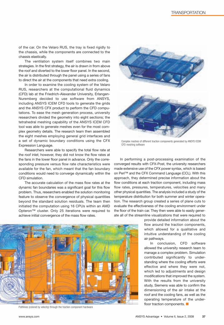
Complex meshes of different traction components generated by ANSYS ICEMCFD meshing software
In performing a post-processing examination of the converged results with CFX-Post, the university researchersmade extensive use of the CFX power syntax, which is basedon Perl™ and the CFX Command Language (CCL). With thisapproach, they determined precise information about theflow conditions at each traction component, including massflow rates, pressures, temperatures, velocities and manyother physical quantities. The analysis included a study of thetemperature distribution for both summer and winter opera-tion. The research group created a series of plane cuts toevaluate the effectiveness of the cooling environment underthe floor of the train car. They then were able to easily gener-ate all of the streamline visualizations that were required to
provide detailed information about theflow around the traction components,which allowed for a qualitative and intuitive understanding of the cooling air pathways.
In conclusion, CFD softwareallowed the university research team tomanage a complex problem. Simulation contributed significantly to under-standing where the cooling efforts wereeffective and where they were not,which led to adjustments and designmodifications that improved the system.With the results from the universitystudy, Siemens was able to confirm thedimensioning of the air intake at the roof and the cooling fans, as well as theoperating temperature of the under-floor traction components. ■
Pathlines (colored by velocity) through the traction component hardware
ANSYS Advantage • Volume II, Issue 2, 2008www.ansys.com 37
TRANSPORTATION
of the car. On the Velaro RUS, the tray is fixed rigidly to the chassis, while the components are connected to the chassis elastically.
The ventilation system itself combines two main strategies. In the first strategy, the air is drawn in from above the roof and diverted to the lower floor panel. In the second,the air is distributed through the panel using a series of fansto direct the air at the components that need extra cooling.
In order to examine the cooling system of the VelaroRUS, researchers at the computational fluid dynamics(CFD) lab at the Friedrich-Alexander University, Erlangen-Nuremberg decided to use software from ANSYS,including ANSYS ICEM CFD tools to generate the gridsand the ANSYS CFX product to perform the CFD compu-tations. To ease the mesh generation process, universityresearchers divided the geometry into eight sections; thetetrahedral meshing capability of the ANSYS ICEM CFDtool was able to generate meshes even for the most com-plex geometry details. The research team then assembledthe eight meshes employing general grid interfaces and a set of dynamic boundary conditions using the CFXExpression Language.
Researchers were able to specify the total flow rate atthe roof inlet; however, they did not know the flow rates atthe fans in the lower floor panel in advance. Only the corre-sponding pressure versus flow rate characteristics wereavailable for the fan, which meant that the fan boundaryconditions would need to converge dynamically within theCFD simulation.
The accurate calculation of the mass flow rates at thedynamic fan boundaries was a significant goal for this flowproblem. Thus, researchers enabled the solution monitoring feature to observe the convergence of physical quantitiesbeyond the standard solution residuals. The team then initiated the computation using 16 CPUs within an AMDOpteron™ cluster. Only 25 iterations were required toachieve initial convergence of the mass flow rates.
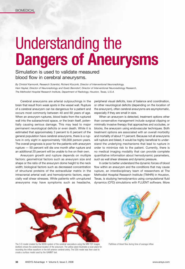
Pathlines of blood flow during time of average inflow
Cerebral aneurysms are arterial outpouchings in thebrain that result from weak spots in the vessel wall. Ruptureof a cerebral aneurysm can be dangerous for a patient andoccurs most commonly between 40 and 60 years of age.When an aneurysm ruptures, blood leaks from the rupturedwall into the subarachnoid space, or the brain itself, poten-tially causing serious damage. This may lead to majorpermanent neurological deficits or even death. While it isestimated that approximately 3 percent to 6 percent of thegeneral population have cerebral aneurysms, there is a rup-ture in only eight in approximately 100,000 person-years.The overall prognosis is poor for the patients with aneurysmrupture — 50 percent will die one month after rupture andan additional 20 percent will be unable to live on their own.
Aneurysm growth and rupture depends on multiple factors: geometrical factors such as aneurysm size andshape or the ratio of the aneurysm dome height to the neckwidth; biological factors such as decreased concentrationof structural proteins of the extracellular matrix in theintracranial arterial wall; and hemodynamic factors, espe-cially wall shear stresses. While patients with unrupturedaneurysms may have symptoms such as headache,
peripheral visual deficits, loss of balance and coordination,or other neurological deficits (depending on the location ofthe aneurysm), often cerebral aneurysms are asymptomatic,especially if they are small in size.
When an aneurysm is detected, treatment options otherthan conservative management include surgical clipping orminimally invasive therapy that approaches and occludes, orblocks, the aneurysm using endovascular techniques. Bothtreatment options are associated with an overall morbidityand mortality of about 11 percent. Because not all aneurysmswill rupture and bleed, it would be highly beneficial to under-stand the underlying mechanisms that lead to rupture inorder to minimize risk to the patient. Currently, there is no medical imaging modality that can provide completequantitative information about hemodynamic parameters,such as wall shear stresses and dynamic pressure.
In order to better understand the dynamic forces of bloodflow within an aneurysm and the conditions that may causerupture, an interdisciplinary team of researchers at TheMethodist Hospital Research Institute (TMHRI) in Houston,Texas, is studying hemodynamics using computational fluiddynamics (CFD) simulations with FLUENT software. More
Understanding theDangers of AneurysmsSimulation is used to validate measured blood flow in cerebral aneurysms.By Christof Karmonik, Research Scientist, Richard Klucznik, Director of Interventional Neuroradiology,
Hani Haykal, Director of Neuroradiology and Goetz Benndorf, Director of Interventional Neuroradiology Research,
The Methodist Hospital Research Institute, Department of Radiology, Houston, Texas, U.S.A.
www.ansys.comANSYS Advantage • Volume II, Issue 2, 200838
BIOMEDICAL
The 3-D model created by the NOVA system of the cerebral vasculature using the MRI TOF images(bottom) shows the anatomical location of the aneurysm. The yellow plane illustrates a scan plane forrecording the inflow waveform in the left anterior cerebral artery. The DSA model was then used tocreate a surface model used by the GAMBIT tool.
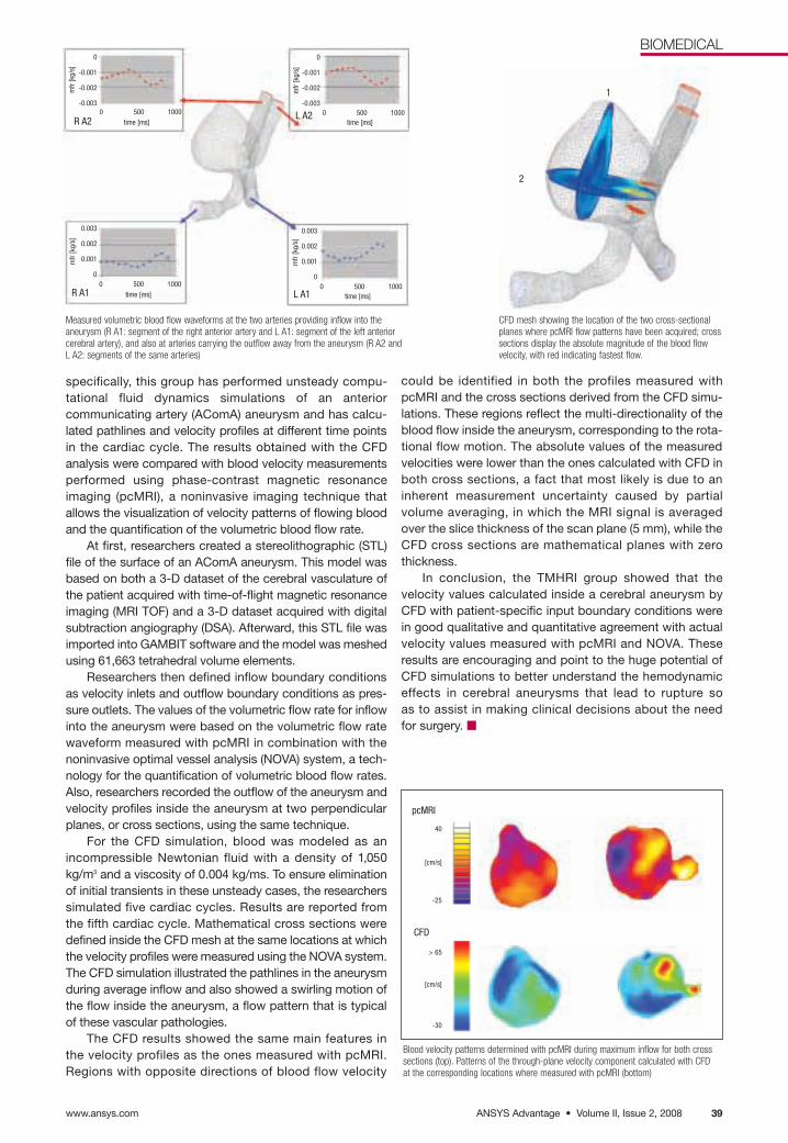
could be identified in both the profiles measured withpcMRI and the cross sections derived from the CFD simu-lations. These regions reflect the multi-directionality of theblood flow inside the aneurysm, corresponding to the rota-tional flow motion. The absolute values of the measuredvelocities were lower than the ones calculated with CFD inboth cross sections, a fact that most likely is due to aninherent measurement uncertainty caused by partial volume averaging, in which the MRI signal is averagedover the slice thickness of the scan plane (5 mm), while theCFD cross sections are mathematical planes with zerothickness.
In conclusion, the TMHRI group showed that thevelocity values calculated inside a cerebral aneurysm byCFD with patient-specific input boundary conditions werein good qualitative and quantitative agreement with actualvelocity values measured with pcMRI and NOVA. Theseresults are encouraging and point to the huge potential ofCFD simulations to better understand the hemodynamiceffects in cerebral aneurysms that lead to rupture so as to assist in making clinical decisions about the need for surgery. ■
Measured volumetric blood flow waveforms at the two arteries providing inflow into theaneurysm (R A1: segment of the right anterior artery and L A1: segment of the left anteriorcerebral artery), and also at arteries carrying the outflow away from the aneurysm (R A2 andL A2: segments of the same arteries)
CFD mesh showing the location of the two cross-sectionalplanes where pcMRI flow patterns have been acquired; crosssections display the absolute magnitude of the blood flowvelocity, with red indicating fastest flow.
Blood velocity patterns determined with pcMRI during maximum inflow for both cross sections (top). Patterns of the through-plane velocity component calculated with CFDat the corresponding locations where measured with pcMRI (bottom)
ANSYS Advantage • Volume II, Issue 2, 2008www.ansys.com 39
BIOMEDICAL
1
2
R A2
R A1
L A2
L A10 500 1000 0 500 1000
0 500 10000 500 1000
time [ms]
time [ms] time [ms]
time [ms]
mfr
[kg/
s]m
fr [k
g/s]
mfr
[kg/
s]m
fr [k
g/s]
0.003
0.002
0.001
0
0
-0.001
-0.002
-0.003
0
-0.001
-0.002
-0.003
pcMRI
CFD
40
[cm/s]
-25
0.003
0.002
0.001
0
> 65
[cm/s]
-30
specifically, this group has performed unsteady compu-tational fluid dynamics simulations of an anteriorcommunicating artery (AComA) aneurysm and has calcu-lated pathlines and velocity profiles at different time pointsin the cardiac cycle. The results obtained with the CFDanalysis were compared with blood velocity measurementsperformed using phase-contrast magnetic resonance imaging (pcMRI), a noninvasive imaging technique thatallows the visualization of velocity patterns of flowing bloodand the quantification of the volumetric blood flow rate.
At first, researchers created a stereolithographic (STL)file of the surface of an AComA aneurysm. This model wasbased on both a 3-D dataset of the cerebral vasculature ofthe patient acquired with time-of-flight magnetic resonanceimaging (MRI TOF) and a 3-D dataset acquired with digitalsubtraction angiography (DSA). Afterward, this STL file wasimported into GAMBIT software and the model was meshedusing 61,663 tetrahedral volume elements.
Researchers then defined inflow boundary conditionsas velocity inlets and outflow boundary conditions as pres-sure outlets. The values of the volumetric flow rate for inflowinto the aneurysm were based on the volumetric flow ratewaveform measured with pcMRI in combination with thenoninvasive optimal vessel analysis (NOVA) system, a tech-nology for the quantification of volumetric blood flow rates.Also, researchers recorded the outflow of the aneurysm andvelocity profiles inside the aneurysm at two perpendicularplanes, or cross sections, using the same technique.
For the CFD simulation, blood was modeled as anincompressible Newtonian fluid with a density of 1,050kg/m3 and a viscosity of 0.004 kg/ms. To ensure eliminationof initial transients in these unsteady cases, the researcherssimulated five cardiac cycles. Results are reported from the fifth cardiac cycle. Mathematical cross sections weredefined inside the CFD mesh at the same locations at whichthe velocity profiles were measured using the NOVA system.The CFD simulation illustrated the pathlines in the aneurysmduring average inflow and also showed a swirling motion ofthe flow inside the aneurysm, a flow pattern that is typical of these vascular pathologies.
The CFD results showed the same main features in the velocity profiles as the ones measured with pcMRI.Regions with opposite directions of blood flow velocity
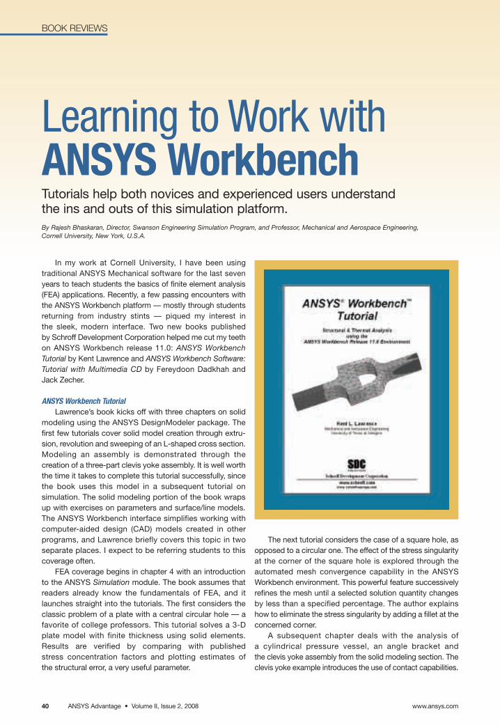
www.ansys.comANSYS Advantage • Volume II, Issue 2, 200840
BOOK REVIEWS
In my work at Cornell University, I have been using traditional ANSYS Mechanical software for the last sevenyears to teach students the basics of finite element analysis(FEA) applications. Recently, a few passing encounters withthe ANSYS Workbench platform — mostly through studentsreturning from industry stints — piqued my interest in the sleek, modern interface. Two new books published by Schroff Development Corporation helped me cut my teeth on ANSYS Workbench release 11.0: ANSYS WorkbenchTutorial by Kent Lawrence and ANSYS Workbench Software:Tutorial with Multimedia CD by Fereydoon Dadkhah and Jack Zecher.
ANSYS Workbench TutorialLawrence’s book kicks off with three chapters on solid
modeling using the ANSYS DesignModeler package. Thefirst few tutorials cover solid model creation through extru-sion, revolution and sweeping of an L-shaped cross section.Modeling an assembly is demonstrated through thecreation of a three-part clevis yoke assembly. It is well worththe time it takes to complete this tutorial successfully, sincethe book uses this model in a subsequent tutorial on simulation. The solid modeling portion of the book wraps up with exercises on parameters and surface/line models.The ANSYS Workbench interface simplifies working with computer-aided design (CAD) models created in other programs, and Lawrence briefly covers this topic in twoseparate places. I expect to be referring students to thiscoverage often.
FEA coverage begins in chapter 4 with an introductionto the ANSYS Simulation module. The book assumes thatreaders already know the fundamentals of FEA, and itlaunches straight into the tutorials. The first considers theclassic problem of a plate with a central circular hole — afavorite of college professors. This tutorial solves a 3-Dplate model with finite thickness using solid elements.Results are verified by comparing with published stress concentration factors and plotting estimates of the structural error, a very useful parameter.
The next tutorial considers the case of a square hole, asopposed to a circular one. The effect of the stress singularityat the corner of the square hole is explored through the automated mesh convergence capability in the ANSYSWorkbench environment. This powerful feature successivelyrefines the mesh until a selected solution quantity changesby less than a specified percentage. The author explainshow to eliminate the stress singularity by adding a fillet at theconcerned corner.
A subsequent chapter deals with the analysis of a cylindrical pressure vessel, an angle bracket and the clevis yoke assembly from the solid modeling section. Theclevis yoke example introduces the use of contact capabilities.
Learning to Work withANSYS WorkbenchTutorials help both novices and experienced users understand the ins and outs of this simulation platform.By Rajesh Bhaskaran, Director, Swanson Engineering Simulation Program, and Professor, Mechanical and Aerospace Engineering, Cornell University, New York, U.S.A.
BOOK REVIEWS
ANSYS Advantage • Volume II, Issue 2, 2008www.ansys.com 41
Lawrence revisits the plate-with-a-hole, pressure vessel andbracket problems, and solves them using a 2-D or surfacemodel. In each case, results for the solid and simplifiedmodels compare well. Other tutorials include analysis ofnatural frequencies, buckling, heat transfer and thermalstresses.
Instructions in the tutorials are terse, so the reader mustperuse both the text and menu snapshots to be able to successfully complete the tutorials, as the two are notredundant. In some cases, the menus on my computer wereslightly different from the ones shown in the book, eventhough I was using version 11.0. With some digging around,however, I was able to compensate for these differencesand proceed with the tutorials.
ANSYS Workbench Software: Tutorial with Multimedia CDWhile Lawrence’s book focuses on ANSYS Workbench
applications, Dadkhah and Zecher’s book integrates discussion of basic finite element modeling concepts withtutorials using the ANSYS Workbench platform. Fundamentalconcepts considered include stiffness matrices, loads andsupports, solid elements, 2-D/axisymmetric models, andmesh refinement/quality. The chapter on stiffness matricesanalyzes a system with two springs, so shape functions arenot covered.
Discussions about modeling concepts are accompa-nied by tutorials that focus on illustrating the concepts inANSYS Workbench applications. For instance, discussionof mesh refinement and quality precedes a tutorial on usingconvergence to improve results for the normal stress in thefillet region of a T-section. This lets readers see the concepts in action in an actual FEA calculation.
Most tutorials deal with fundamental problems, such asa straight beam, plate-with-a-hole and cylindrical pressurevessel. This allows the authors to check their FEA resultsagainst hand calculations or handbook results, which theyare very diligent about. This is a sound pedagogicalapproach to teaching the fundamentals to an FEA novice, and it will help instructors emphasize the importance of verifying FEA results.
Dadkhah and Zecher present tutorials on solid modeling using the ANSYS DesignModeler tool at the startof the book. This material covers some of the same territoryas Lawrence’s book. FEA chapters include tutorials on 3-Dsolid elements, plane stress/strain, shell elements, vibration(natural frequencies and mode shapes) and steady-stateheat transfer. More advanced concepts, such as contact,assemblies and fatigue loading, are not considered. Overall,the focus is on understanding the fundamentals throughsolving canonical problems.
There are a few exercises at the end of each chapter thatprovide opportunities for further exploration and practice.These would work well as homework problems. The bookcomes with a CD containing videos of each tutorial in AVI
format, as well as model files and a material database used insome of the tutorials and exercises. The book ends with ashort chapter on the role of FEA in engineering and issuesrelated to its appropriate use. This chapter raises severalissues worth chewing on, such as absolute versus compara-tive answers, establishing goals for the analysis, interpretingresults and performing failure analysis.
In the educational setting, there are two importantaspects in learning to use the ANSYS Workbench environ-ment to obtain reliable engineering solutions. First, studentsneed to develop the necessary skills to use the softwareinterface in order to set up and solve a variety of engineeringproblems. Second, they need to understand the underlyingconcepts to apply the software correctly in order to obtainvalidated results. Either book will help students learn theinterface, with Lawrence’s book additionally addressingmore advanced topics such as contact, assemblies andfatigue loading. Dadkhah and Zecher’s book has more substantial discussion of the underlying concepts and, thus,is more suitable for the novice. Both books certainly are recommended additions to your engineering bookshelf. ■
For further information on the books ANSYS Workbench Tutorialby Kent Lawrence and ANSYS Workbench Software: Tutorial with Multimedia CD by Fereydoon Dadkhah and Jack Zecher, contact the publisher, Schroff Development Corporation, at 913.262.2664,or visit www.sdcpublications.com.
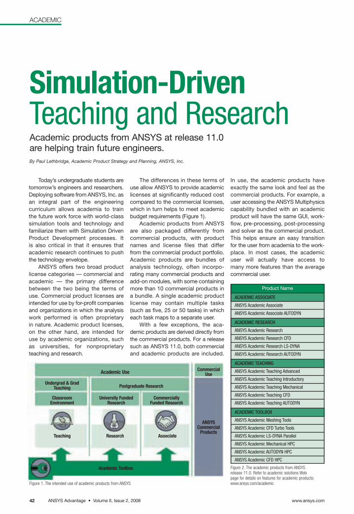
Academic Toolbox
Teaching Research
Academic Use
Undergrad & GradTeaching Postgraduate Research
ClassroomEnvironment
University FundedResearch
Commercially Funded Research
CommercialUse
ANSYSCommercial
ProductsAssociate
Today’s undergraduate students aretomorrow’s engineers and researchers.Deploying software from ANSYS, Inc. asan integral part of the engineering curriculum allows academia to train the future work force with world-classsimulation tools and technology andfamiliarize them with Simulation DrivenProduct Development processes. It is also critical in that it ensures that academic research continues to pushthe technology envelope.
ANSYS offers two broad productlicense categories — commercial andacademic — the primary differencebetween the two being the terms of use. Commercial product licenses areintended for use by for-profit companiesand organizations in which the analysiswork performed is often proprietary in nature. Academic product licenses,on the other hand, are intended for use by academic organizations, such as universities, for nonproprietary teaching and research.
Figure 2. The academic products from ANSYSrelease 11.0. Refer to academic solutions Webpage for details on features for academic products:www.ansys.com/academic
Product Name
ACADEMIC ASSOCIATE
ANSYS Academic Associate
ANSYS Academic Associate AUTODYN
ACADEMIC RESEARCH
ANSYS Academic Research
ANSYS Academic Research CFD
ANSYS Academic Research LS-DYNA
ANSYS Academic Research AUTODYN
ACADEMIC TEACHING
ANSYS Academic Teaching Advanced
ANSYS Academic Teaching Introductory
ANSYS Academic Teaching Mechanical
ANSYS Academic Teaching CFD
ANSYS Academic Teaching AUTODYN
ACADEMIC TOOLBOX
ANSYS Academic Meshing Tools
ANSYS Academic CFD Turbo Tools
ANSYS Academic LS-DYNA Parallel
ANSYS Academic Mechanical HPC
ANSYS Academic AUTODYN HPC
ANSYS Academic CFD HPC
ACADEMIC
Simulation-DrivenTeaching and Research Academic products from ANSYS at release 11.0 are helping train future engineers.By Paul Lethbridge, Academic Product Strategy and Planning, ANSYS, Inc.
Figure 1. The intended use of academic products from ANSYS
The differences in these terms ofuse allow ANSYS to provide academiclicenses at significantly reduced costcompared to the commercial licenses,which in turn helps to meet academicbudget requirements (Figure 1).
Academic products from ANSYSare also packaged differently fromcommercial products, with productnames and license files that differ from the commercial product portfolio. Academic products are bundles ofanalysis technology, often incorpo-rating many commercial products andadd-on modules, with some containingmore than 10 commercial products in a bundle. A single academic productlicense may contain multiple tasks(such as five, 25 or 50 tasks) in whicheach task maps to a separate user.
With a few exceptions, the aca-demic products are derived directly fromthe commercial products. For a releasesuch as ANSYS 11.0, both commercialand academic products are included.
In use, the academic products have exactly the same look and feel as thecommercial products. For example, auser accessing the ANSYS Multiphysicscapability bundled with an academicproduct will have the same GUI, work-flow, pre-processing, post-processingand solver as the commercial product.This helps ensure an easy transition for the user from academia to the work-place. In most cases, the academic user will actually have access to many more features than the averagecommercial user.
www.ansys.comANSYS Advantage • Volume II, Issue 2, 200842
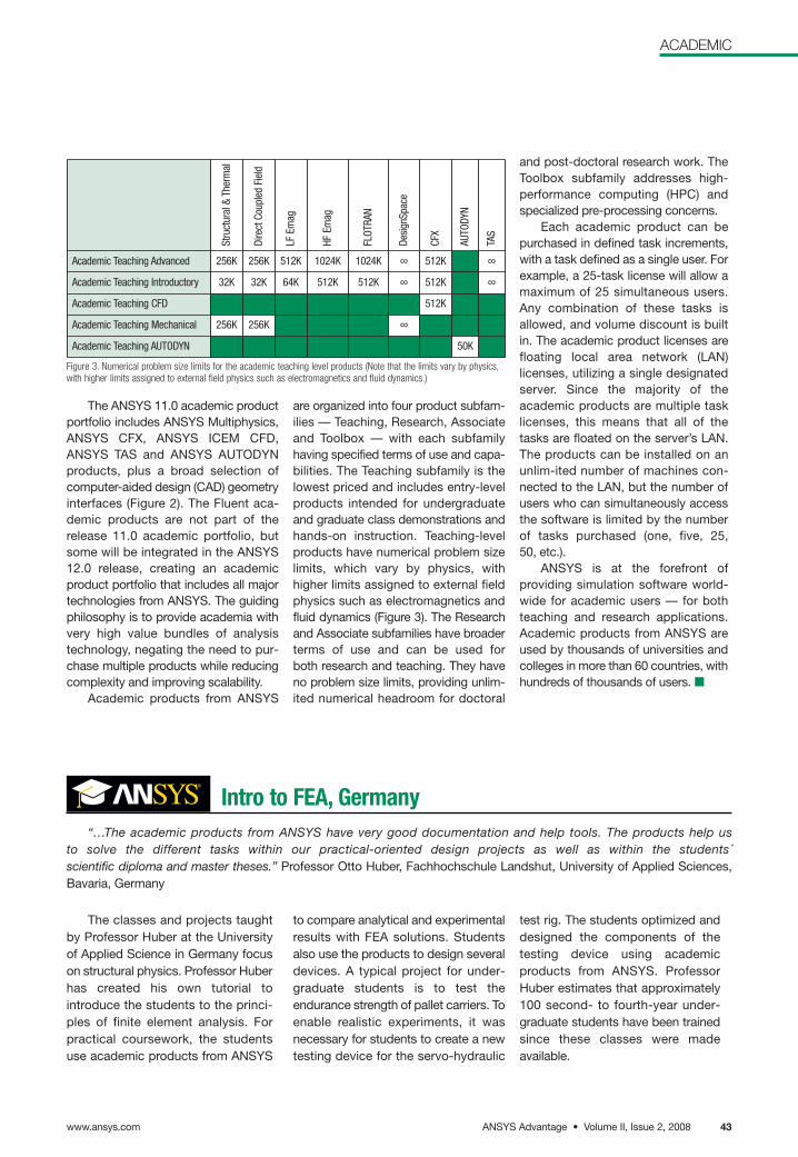
ACADEMIC
Figure 3. Numerical problem size limits for the academic teaching level products (Note that the limits vary by physics,with higher limits assigned to external field physics such as electromagnetics and fluid dynamics.)
Stru
ctur
al &
Ther
mal
Dire
ct C
oupl
ed F
ield
LF E
mag
HF E
mag
FLOT
RAN
Desi
gnSp
ace
CFX
AUTO
DYN
TAS
Academic Teaching Advanced 256K 256K 512K 1024K 1024K ∞ 512K ∞
Academic Teaching Introductory 32K 32K 64K 512K 512K ∞ 512K ∞
Academic Teaching CFD 512K
Academic Teaching Mechanical 256K 256K ∞
Academic Teaching AUTODYN 50K
The ANSYS 11.0 academic productportfolio includes ANSYS Multiphysics,ANSYS CFX, ANSYS ICEM CFD,ANSYS TAS and ANSYS AUTODYN products, plus a broad selection ofcomputer-aided design (CAD) geometryinterfaces (Figure 2). The Fluent aca-demic products are not part of therelease 11.0 academic portfolio, butsome will be integrated in the ANSYS12.0 release, creating an academicproduct portfolio that includes all majortechnologies from ANSYS. The guidingphilosophy is to provide academia withvery high value bundles of analysistechnology, negating the need to pur-chase multiple products while reducingcomplexity and improving scalability.
Academic products from ANSYS
are organized into four product subfam-ilies — Teaching, Research, Associateand Toolbox — with each subfamilyhaving specified terms of use and capa-bilities. The Teaching subfamily is thelowest priced and includes entry-levelproducts intended for undergraduateand graduate class demonstrations andhands-on instruction. Teaching-levelproducts have numerical problem sizelimits, which vary by physics, with higher limits assigned to external fieldphysics such as electromagnetics andfluid dynamics (Figure 3). The Researchand Associate subfamilies have broaderterms of use and can be used for both research and teaching. They have no problem size limits, providing unlim-ited numerical headroom for doctoral
and post-doctoral research work. TheToolbox subfamily addresses high-performance computing (HPC) andspecialized pre-processing concerns.
Each academic product can bepurchased in defined task increments,with a task defined as a single user. Forexample, a 25-task license will allow amaximum of 25 simultaneous users.Any combination of these tasks isallowed, and volume discount is builtin. The academic product licenses arefloating local area network (LAN) licenses, utilizing a single designatedserver. Since the majority of the academic products are multiple tasklicenses, this means that all of thetasks are floated on the server’s LAN.The products can be installed on anunlim-ited number of machines con-nected to the LAN, but the number ofusers who can simultaneously accessthe software is limited by the numberof tasks purchased (one, five, 25, 50, etc.).
ANSYS is at the forefront of providing simulation software world-wide for academic users — for bothteaching and research applications.Academic products from ANSYS areused by thousands of universities andcolleges in more than 60 countries, withhundreds of thousands of users. ■
The classes and projects taughtby Professor Huber at the Universityof Applied Science in Germany focuson structural physics. Professor Huberhas created his own tutorial to introduce the students to the princi-ples of finite element analysis. Forpractical coursework, the studentsuse academic products from ANSYS
to compare analytical and experimentalresults with FEA solutions. Studentsalso use the products to design severaldevices. A typical project for under-graduate students is to test theendurance strength of pallet carriers. Toenable realistic experiments, it wasnecessary for students to create a newtesting device for the servo-hydraulic
test rig. The students optimized anddesigned the components of thetesting device using academic products from ANSYS. ProfessorHuber estimates that approximately100 second- to fourth-year under-graduate students have been trainedsince these classes were made available.
“…The academic products from ANSYS have very good documentation and help tools. The products help us to solve the different tasks within our practical-oriented design projects as well as within the students´scientific diploma and master theses.” Professor Otto Huber, Fachhochschule Landshut, University of Applied Sciences,Bavaria, Germany
Intro to FEA, Germany
ANSYS Advantage • Volume II, Issue 2, 2008www.ansys.com 43
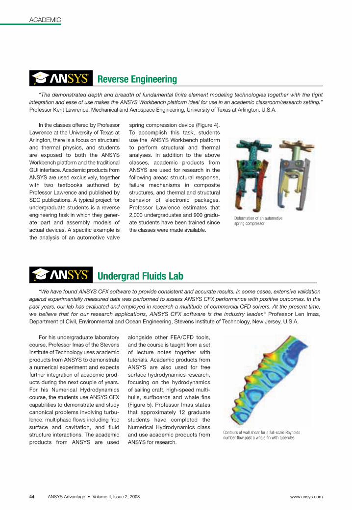
ACADEMIC
“We have found ANSYS CFX software to provide consistent and accurate results. In some cases, extensive validationagainst experimentally measured data was performed to assess ANSYS CFX performance with positive outcomes. In thepast years, our lab has evaluated and employed in research a multitude of commercial CFD solvers. At the present time,we believe that for our research applications, ANSYS CFX software is the industry leader.” Professor Len Imas, Department of Civil, Environmental and Ocean Engineering, Stevens Institute of Technology, New Jersey, U.S.A.
Contours of wall shear for a full-scale Reynoldsnumber flow past a whale fin with tubercles
For his undergraduate laboratorycourse, Professor Imas of the StevensInstitute of Technology uses academicproducts from ANSYS to demonstratea numerical experiment and expectsfurther integration of academic prod-ucts during the next couple of years.For his Numerical Hydrodynamicscourse, the students use ANSYS CFXcapabilities to demonstrate and studycanonical problems involving turbu-lence, multiphase flows including freesurface and cavitation, and fluid structure interactions. The academicproducts from ANSYS are used
alongside other FEA/CFD tools,and the course is taught from a setof lecture notes together with tutorials. Academic products fromANSYS are also used for free surface hydrodynamics research,focusing on the hydrodynamics of sailing craft, high-speed multi-hulls, surfboards and whale fins(Figure 5). Professor Imas statesthat approximately 12 graduatestudents have completed theNumerical Hydrodynamics classand use academic products fromANSYS for research.
Undergrad Fluids Lab
“The demonstrated depth and breadth of fundamental finite element modeling technologies together with the tight integration and ease of use makes the ANSYS Workbench platform ideal for use in an academic classroom/research setting.”Professor Kent Lawrence, Mechanical and Aerospace Engineering, University of Texas at Arlington, U.S.A.
Deformation of an automotivespring compressor
In the classes offered by ProfessorLawrence at the University of Texas atArlington, there is a focus on structuraland thermal physics, and students are exposed to both the ANSYS Workbench platform and the traditionalGUI interface. Academic products fromANSYS are used exclusively, togetherwith two textbooks authored by Professor Lawrence and published bySDC publications. A typical project forundergraduate students is a reverseengineering task in which they gener-ate part and assembly models ofactual devices. A specific example isthe analysis of an automotive valve
spring compression device (Figure 4).To accomplish this task, students use the ANSYS Workbench platformto perform structural and thermalanalyses. In addition to the aboveclasses, academic products fromANSYS are used for research in the following areas: structural response,failure mechanisms in compositestructures, and thermal and structuralbehavior of electronic packages. Professor Lawrence estimates that2,000 undergraduates and 900 gradu-ate students have been trained sincethe classes were made available.
Reverse Engineering
www.ansys.comANSYS Advantage • Volume II, Issue 2, 200844
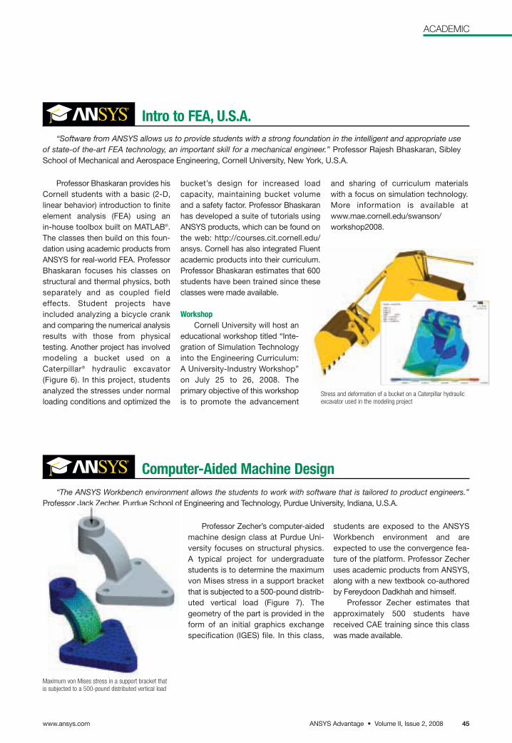
ACADEMIC
Professor Bhaskaran provides hisCornell students with a basic (2-D, linear behavior) introduction to finiteelement analysis (FEA) using an in-house toolbox built on MATLAB®.The classes then build on this foun-dation using academic products fromANSYS for real-world FEA. ProfessorBhaskaran focuses his classes onstructural and thermal physics, bothseparately and as coupled fieldeffects. Student projects haveincluded analyzing a bicycle crankand comparing the numerical analysisresults with those from physical testing. Another project has involvedmodeling a bucket used on a Caterpillar® hydraulic excavator (Figure 6). In this project, studentsanalyzed the stresses under normalloading conditions and optimized the
bucket’s design for increased load capacity, maintaining bucket volume and a safety factor. Professor Bhaskaranhas developed a suite of tutorials usingANSYS products, which can be found on the web: http://courses.cit.cornell.edu/ansys. Cornell has also integrated Fluentacademic products into their curriculum.Professor Bhaskaran estimates that 600students have been trained since theseclasses were made available.
WorkshopCornell University will host an
educational workshop titled “Inte-gration of Simulation Technologyinto the Engineering Curriculum:A University-Industry Workshop”on July 25 to 26, 2008. The primary objective of this workshopis to promote the advancement
and sharing of curriculum materials with a focus on simulation technology.More information is available atwww.mae.cornell.edu/swanson/workshop2008.
Stress and deformation of a bucket on a Caterpillar hydraulicexcavator used in the modeling project
“Software from ANSYS allows us to provide students with a strong foundation in the intelligent and appropriate useof state-of the-art FEA technology, an important skill for a mechanical engineer.” Professor Rajesh Bhaskaran, SibleySchool of Mechanical and Aerospace Engineering, Cornell University, New York, U.S.A.
“The ANSYS Workbench environment allows the students to work with software that is tailored to product engineers.”Professor Jack Zecher, Purdue School of Engineering and Technology, Purdue University, Indiana, U.S.A.
Professor Zecher’s computer-aidedmachine design class at Purdue Uni-versity focuses on structural physics. A typical project for undergraduate students is to determine the maximumvon Mises stress in a support bracketthat is subjected to a 500-pound distrib-uted vertical load (Figure 7). Thegeometry of the part is provided in theform of an initial graphics exchangespecification (IGES) file. In this class,
Intro to FEA, U.S.A.
Computer-Aided Machine Design
Maximum von Mises stress in a support bracket thatis subjected to a 500-pound distributed vertical load
students are exposed to the ANSYSWorkbench environment and areexpected to use the convergence fea-ture of the platform. Professor Zecheruses academic products from ANSYS,along with a new textbook co-authoredby Fereydoon Dadkhah and himself.
Professor Zecher estimates thatapproximately 500 students havereceived CAE training since this classwas made available.
ANSYS Advantage • Volume II, Issue 2, 2008www.ansys.com 45
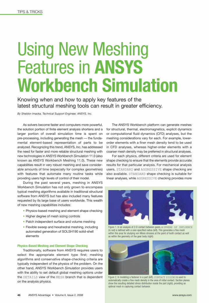
As solvers become faster and computers more powerful,the solution portion of finite element analysis shortens and alarger portion of overall simulation time is spent on pre-processing, including generating the mesh — the funda-mental element-based representation of parts to beanalyzed. Recognizing this trend, ANSYS, Inc. has addressedthe need for faster and more reliable structural meshing withnew technologies in ANSYS Workbench Simulation 11.0 (alsoknown as ANSYS Workbench Meshing 11.0). These newcapabilities result in very robust meshing and save consider-able amounts of time (especially for complex geometries)with features that automate many routine tasks while providing users high levels of control of their model.
During the past several years, meshing in ANSYS Workbench Simulation has not only grown to encompasstypical meshing algorithms available in traditional structuralsoftware from ANSYS but has also included many featuresrequested by its large base of users worldwide. This wealthof new meshing capabilities includes:
• Physics-based meshing and element shape checking
• Higher degree of mesh sizing controls
• Patch independent surface and volume meshing
• Flexible sweep and hexahedral meshing, includingautomated generation of SOLSH190 solid-shell elements
Physics-Based Meshing and Element Shape CheckingTraditionally, software from ANSYS requires users to
select the appropriate element type first; meshing algorithms and conservative shape-checking criteria aretypically independent of the physics of the problem. On theother hand, ANSYS Workbench Simulation provides userswith the ability to set default global meshing options underthe DETAILS view of the MESH branch that is dependenton the analysis physics.
The ANSYS Workbench platform can generate meshesfor structural, thermal, electromagnetics, explicit dynamics or computational fluid dynamics (CFD) analyses, but the meshing considerations vary for each. For example, lower-order elements with a finer mesh density tend to be used in CFD analyses, whereas higher-order elements with acoarser mesh density may be preferred in structural analyses.
For each physics, different criteria are used for elementshape checking to ensure that the elements provide accurateresults for that particular analysis. For mechanical analysisusers, STANDARD and AGGRESSIVE shape checking arealso available. STANDARD shape checking is suitable for linear analyses, while AGGRESSIVE checking provides more
Using New MeshingFeatures in ANSYSWorkbench Simulation Knowing when and how to apply key features of the latest structural meshing tools can result in greater efficiency.By Sheldon Imaoka, Technical Support Engineer, ANSYS, Inc.
Figure 2. In modeling a fastener in a part (left), CONTACT SIZING is used to automatically create a fine mesh density in the area of initial contact. Section planesshow the resulting detailed stress distribution inside the part (right), providing an optimal mesh in capturing contact behavior.
Figure 1. In an analysis of 2-D contact between gears, a SPHERE OF INFLUENCE(in red) is defined with a user-specified radius (left). This generates a fine mesh within this area for studying von Mises stresses at the point of tooth contact as well as within the geometry of the gear body (right).
www.ansys.comANSYS Advantage • Volume II, Issue 2, 200846
TIPS & TRICKS
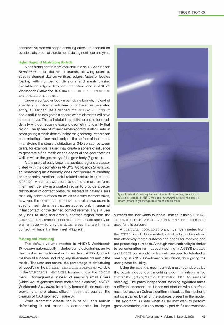
surfaces the user wants to ignore. Instead, either VIRTUALTOPOLOGY or the PATCH INDEPENDENT MESHER can beused for this purpose.
A VIRTUAL TOPOLOGY branch can be inserted fromthe MODEL branch. Once added, virtual cells can be definedthat effectively merge surfaces and edges for meshing andpre-processing purposes. Although the functionality is similarto concatenation for mapped meshing in ANSYS (ACCATand LCCAT commands), virtual cells are used for tetrahedralmeshing in ANSYS Workbench Simulation, thus giving theuser greater flexibility.
Using the METHOD mesh control, a user can also utilizethe patch independent meshing algorithm (also namedUNIFORM QUAD/TRI or UNIFORM TRI for surfacemeshing). The patch independent meshing algorithm takesa different approach, as it does not start off with a surfacemesh but uses an Octree algorithm instead, so the mesher isnot constrained by all of the surfaces present in the model.This algorithm is useful when a user may want to performgross defeaturing of a very complex part or if a user wants to
conservative element shape-checking criteria to account forpossible distortion of the elements during nonlinear analyses.
Higher Degree of Mesh Sizing ControlsMesh sizing controls are available in ANSYS Workbench
Simulation under the MESH branch, allowing users to specify element size on vertices, edges, faces or bodies(parts), with number of divisions and mesh biasing available on edges. Two features introduced in ANSYSWorkbench Simulation 10.0 are SPHERE OF INFLUENCEand CONTACT SIZING.
Under a surface or body mesh sizing branch, instead ofspecifying a uniform mesh density for the entire geometricentity, a user can use a defined COORDINATE SYSTEMand a radius to designate a sphere where elements will havea certain size. This is helpful in specifying a smaller mesh density without requiring existing geometry to identify thatregion. The sphere of influence mesh control is also useful inpropagating a mesh density inside the geometry, rather thanconcentrating a finer mesh only on the surface of the model.In analyzing the stress distribution of 2-D contact betweengears, for example, a user may create a sphere of influenceto generate a fine mesh on the edges of the gear teeth aswell as within the geometry of the gear body (Figure 1).
Many users already know that contact regions are asso-ciated with the geometry in ANSYS Workbench Simulation,so remeshing an assembly does not require re-creatingcontact pairs. Another useful related feature is CONTACTSIZING, which allows users to define a more uniform, finer mesh density in a contact region to provide a betterdistribution of contact pressure. Instead of having usersmanually select surfaces on which to define element sizes,however, the CONTACT SIZING control allows users tospecify mesh densities that are applied only in areas of initial contact for the defined contact regions. Thus, a useronly has to drag-and-drop a contact region from the CONNECTIONS branch to the MESH branch and specify anelement size — so only the actual areas that are in initialcontact will have that finer mesh (Figure 2).
Meshing and DefeaturingThe default volume mesher in ANSYS Workbench
Simulation automatically includes some defeaturing, unlikethe mesher in traditional software from ANSYS, whichmeshes all surfaces, including any sliver areas present in themodel. The user can control the percentage of defeaturingby specifying the DSMESH DEFEATUREPERCENT variablein the VARIABLE MANAGER located under the TOOLSmenu. Consequently, instead of meshing small slivers(which would generate more nodes and elements), ANSYS Workbench Simulation internally ignores these surfaces, providing a more robust, efficient mesh that requires littlecleanup of CAD geometry (Figure 3).
While automatic defeaturing is helpful, this built-in defeaturing is not meant to compensate for larger
Figure 3. Instead of modeling the small sliver in this model (top), the automaticdefeaturing capability in ANSYS Workbench Simulation intentionally ignores thissurface (bottom) in generating a more robust, efficient mesh.
ANSYS Advantage • Volume II, Issue 2, 2008www.ansys.com 47
TIPS & TRICKS
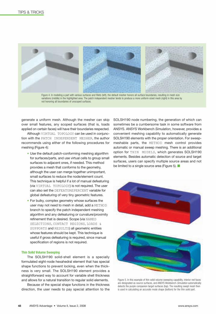
generate a uniform mesh. Although the mesher can skip over small features, any scoped surfaces (that is, loads applied on certain faces) will have their boundaries respected.
Although VIRTUAL TOPOLOGY can be used in conjunc-tion with the PATCH INDEPENDENT MESHER, the authorrecommends using either of the following procedures formeshing (Figure 4):
• Use the default patch-conforming meshing algorithmfor surfaces/parts, and use virtual cells to group smallsurfaces to adjacent ones, if needed. This methodprovides a mesh that conforms to the geometry,although the user can merge together unimportant,small surfaces to reduce the node/element count.This technique is helpful if a lot of manual defeaturing(via VIRTUAL TOPOLOGY) is not required. The usercan also set the DEFEATUREPERCENT variable forglobal defeaturing of very tiny geometric features.
• For bulky, complex geometry whose surfaces theuser may not need to mesh in detail, add a METHODbranch to specify the patch independent meshingalgorithm and any defeaturing or curvature/proximityrefinement that is desired. Scope (via NAMEDSELECTIONS, CONTACT REGIONS, LOADS &SUPPORTS and RESULTS) all geometric entitieswhose features should be kept. This technique is useful if gross defeaturing is required, since manualspecification of regions is not required.
Thin Solid Volume SweepingThe SOLSH190 solid-shell element is a specially
formulated eight-node hexahedral element that has specialshape functions to prevent locking, even when the thick-ness is very small. The SOLSH190 element provides astraightforward way to account for variable shell thicknessand allows for a natural transition to regular solid elements.
Because of the special shape functions in the thicknessdirection, the user needs to pay special attention to the
Figure 5. In this example of thin solid volume sweeping capability, interior red facesare designated as source surfaces, and ANSYS Workbench Simulation automaticallydetects the purple companion target surfaces (top). The resulting swept mesh thenis used in calculating an accurate mode shape (bottom) for the thin solid part.
Figure 4. In modeling a part with various surfaces and fillets (left), the default mesher honors all surface boundaries, resulting in mesh sizevariations (middle) in the highlighted area. The patch independent mesher tends to produce a more uniform-sized mesh (right) in this area bynot honoring all boundaries of unscoped surfaces.
SOLSH190 node numbering, the generation of which cansometimes be a cumbersome task in some software fromANSYS. ANSYS Workbench Simulation, however, provides aconvenient meshing capability to automatically generateSOLSH190 elements with the proper orientation. For sweep-meshable parts, the METHOD mesh control providesautomatic or manual sweep meshing. There is an additionaloption for THIN MODELS, which generates SOLSH190 elements. Besides automatic detection of source and targetsurfaces, users can specify multiple source areas and not be limited to a single source area (Figure 5). ■
www.ansys.comANSYS Advantage • Volume II, Issue 2, 200848
TIPS & TRICKS
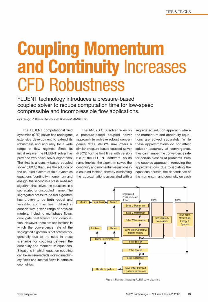
The FLUENT computational fluiddynamics (CFD) solver has undergoneextensive development to extend itsrobustness and accuracy for a widerange of flow regimes. Since its initial release, the FLUENT solver has provided two basic solver algorithms:The first is a density-based coupledsolver (DBCS) that uses the solution ofthe coupled system of fluid dynamics equations (continuity, momentum andenergy); the second is a pressure-basedalgorithm that solves the equations in asegregated or uncoupled manner. Thesegregated pressure-based algorithmhas proven to be both robust and versatile, and has been utilized in concert with a wide range of physical models, including multiphase flows,conjugate heat transfer and combus-tion. However, there are applications inwhich the convergence rate of the segregated algorithm is not satisfactory,generally due to the need in these scenarios for coupling between the continuity and momentum equations.Situations in which equation couplingcan be an issue include rotating machin-ery flows and internal flows in complexgeometries.
Coupling Momentum and Continuity IncreasesCFD Robustness FLUENT technology introduces a pressure-based coupled solver to reduce computation time for low-speed compressible and incompressible flow applications.By Franklyn J. Kelecy, Applications Specialist, ANSYS, Inc.
Figure 1. Flowchart illustrating FLUENT solver algorithms
Initialize
SegregatedPressure-BasedSolver PBCS DBCS
Begin Loop Solver?
RepeatExit Loop
Check Convergence
Update Properties
Solve U-Momentum
Solve Energy
Solve Species
Solve Turbulence
Solve Other TransportEquations as Required
Solve Mass &Momentum
Solve Mass,Momentum,
Energy &Species
Solve V-Momentum
Solve W-Momentum
Solve Mass Continuity;Update Velocity
The ANSYS CFX solver relies on a pressure-based coupled solverapproach to achieve robust conver-gence rates. ANSYS now offers asimilar pressure-based coupled solver(PBCS) for the first time with version6.3 of the FLUENT software. As itsname implies, the algorithm solves thecontinuity and momentum equations ina coupled fashion, thereby eliminatingthe approximations associated with a
segregated solution approach wherethe momentum and continuity equa-tions are solved separately. Whilethese approximations do not affectsolution accuracy at convergence,they can hamper the convergence ratefor certain classes of problems. With the coupled approach, removing theapproximations due to isolating theequations permits the dependence ofthe momentum and continuity on each
ANSYS Advantage • Volume II, Issue 2, 2008
TIPS & TRICKS
www.ansys.com 49
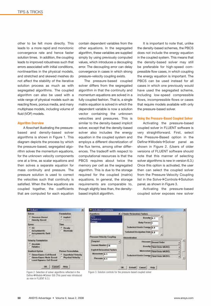
www.ansys.comANSYS Advantage • Volume II, Issue 2, 200850
TIPS & TRICKS
Figure 3. Solution controls for the pressure-based coupled solver
other to be felt more directly. Thisleads to a more rapid and monotonicconvergence rate and hence fastersolution times. In addition, the couplingleads to improved robustness such thaterrors associated with initial conditions,nonlinearities in the physical models,and stretched and skewed meshes donot affect the stability of the iterativesolution process as much as with segregated algorithms. The coupledalgorithm can also be used with awide range of physical models such asreacting flows, porous media, and manymultiphase models, including volume offluid (VOF) models.
Algorithm OverviewA flowchart illustrating the pressure-
based and density-based solveralgorithms is shown in Figure 1. This diagram depicts the process by whichthe pressure-based, segregated algo-rithm solves the momentum equations,for the unknown velocity componentsone at a time, as scalar equations andthen solves a separate equation formass continuity and pressure. The pressure solution is used to correct the velocities such that continuity is satisfied. When the flow equations arecoupled together, the coefficients that are computed for each equation
Figure 2. Selection of solver algorithms reflected in theDefineàModelsàSolver GUI (This panel was introducedas new in FLUENT 6.3.)
contain dependent variables from theother equations. In the segregated algorithm, these variables are suppliedsimply by using previously computedvalues, which introduces a decouplingerror. The decoupling error can delayconvergence in cases in which strongpressure–velocity coupling exists.
The pressure-based coupledsolver differs from the segregatedalgorithm in that the continuity andmomentum equations are solved in afully coupled fashion. That is, a singlematrix equation is solved in which thedependent variable is now a solutionvector containing the unknownvelocities and pressures. This is similar to the density-based implicitsolver, except that the density-basedsolver also includes the energy equation in the coupled system andemploys a different discretization ofthe flux terms, among other differ-ences. The tradeoff with respect tocomputational resources is that thePBCS requires about twice the memory per cell as the segregatedalgorithm. This is due to the storagerequired for the coupled (matrix)equations. In general, the storagerequirements are comparable to,though slightly less than, the density-based implicit algorithm.
It is important to note that, unlikethe density-based schemes, the PBCSdoes not include the energy equationin the coupled system. This means thatthe density-based solver may still be preferable for high-speed com-pressible flow cases, in which couplingthe energy equation is important. ThePBCS can be used instead for allcases in which one previously wouldhave used the segregated scheme,including low-speed compressibleflows, incompressible flows or casesthat require models available with onlythe pressure-based solver.
Using the Pressure-Based Coupled SolverActivating the pressure-based
coupled solver in FLUENT software isvery straightforward. First, select the Pressure-Based option in theDefineàModelsàSolver panel asshown in Figure 2. (Users of older versions of FLUENT software shouldnote that this manner of selectingsolver algorithms is new in version 6.3.)Once this option is activated, the userthen can select the coupled solverfrom the Pressure-Velocity Couplinglist in the SolveàControlsàSolutionpanel, as shown in Figure 3.
Activating the pressure-basedcoupled solver exposes new solver
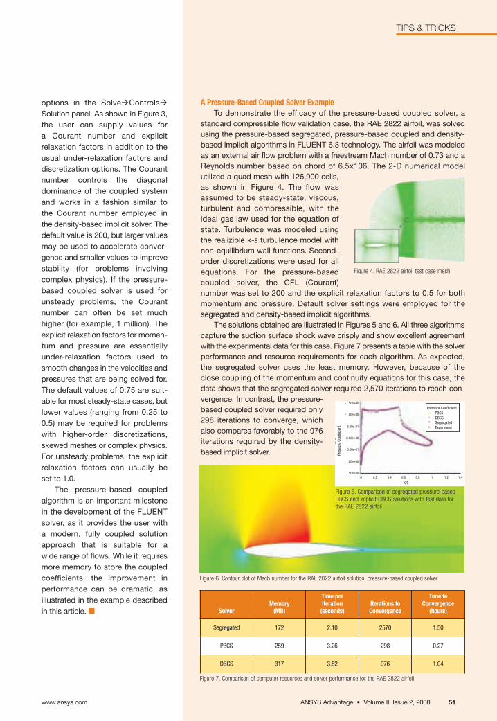
Figure 7. Comparison of computer resources and solver performance for the RAE 2822 airfoil
Figure 6. Contour plot of Mach number for the RAE 2822 airfoil solution: pressure-based coupled solver
A Pressure-Based Coupled Solver ExampleTo demonstrate the efficacy of the pressure-based coupled solver, a
standard compressible flow validation case, the RAE 2822 airfoil, was solvedusing the pressure-based segregated, pressure-based coupled and density-based implicit algorithms in FLUENT 6.3 technology. The airfoil was modeledas an external air flow problem with a freestream Mach number of 0.73 and aReynolds number based on chord of 6.5x10⁶. The 2-D numerical model utilized a quad mesh with 126,900 cells,as shown in Figure 4. The flow wasassumed to be steady-state, viscous,turbulent and compressible, with theideal gas law used for the equation ofstate. Turbulence was modeled usingthe realizible k-ε turbulence model withnon-equilibrium wall functions. Second-order discretizations were used for allequations. For the pressure-based coupled solver, the CFL (Courant) number was set to 200 and the explicit relaxation factors to 0.5 for bothmomentum and pressure. Default solver settings were employed for the segregated and density-based implicit algorithms.
The solutions obtained are illustrated in Figures 5 and 6. All three algorithmscapture the suction surface shock wave crisply and show excellent agreementwith the experimental data for this case. Figure 7 presents a table with the solverperformance and resource requirements for each algorithm. As expected, the segregated solver uses the least memory. However, because of the close coupling of the momentum and continuity equations for this case, the data shows that the segregated solver required 2,570 iterations to reach con-vergence. In contrast, the pressure-based coupled solver required only298 iterations to converge, whichalso compares favorably to the 976iterations required by the density-based implicit solver.
SolverMemory
(MB)
Time per Iteration
(seconds)Iterations to Convergence
Time to Convergence
(hours)
Segregated 172 2.10 2570 1.50
PBCS 259 3.26 298 0.27
DBCS 317 3.82 976 1.04
options in the SolveàControlsàSolution panel. As shown in Figure 3,the user can supply values for a Courant number and explicit relaxation factors in addition to theusual under-relaxation factors anddiscretization options. The Courant number controls the diagonal dominance of the coupled systemand works in a fashion similar to the Courant number employed in the density-based implicit solver. Thedefault value is 200, but larger valuesmay be used to accelerate conver-gence and smaller values to improvestability (for problems involving complex physics). If the pressure-based coupled solver is used forunsteady problems, the Courantnumber can often be set much higher (for example, 1 million). Theexplicit relaxation factors for momen-tum and pressure are essentiallyunder-relaxation factors used tosmooth changes in the velocities andpressures that are being solved for.The default values of 0.75 are suit-able for most steady-state cases, butlower values (ranging from 0.25 to0.5) may be required for problemswith higher-order discretizations,skewed meshes or complex physics.For unsteady problems, the explicitrelaxation factors can usually be set to 1.0.
The pressure-based coupledalgorithm is an important milestonein the development of the FLUENTsolver, as it provides the user with a modern, fully coupled solutionapproach that is suitable for a wide range of flows. While it requiresmore memory to store the coupledcoefficients, the improvement in performance can be dramatic, asillustrated in the example describedin this article. ■
Figure 4. RAE 2822 airfoil test case mesh
0 0.2 0.4 0.6 0.8 1 1.2 1.4
Pressure CoefficientPBCSDBCSSegregatedExperiment
X/C
-1.50e+00
-1.00e+00
-5.00e-01
0.00e+00
5.00e-01
1.00e+00
1.50e+00
Pres
sure
Coe
ffici
ent
Figure 5. Comparison of segregated pressure-basedPBCS and implicit DBCS solutions with test data forthe RAE 2822 airfoil
ANSYS Advantage • Volume II, Issue 2, 2008
TIPS & TRICKS
www.ansys.com 51
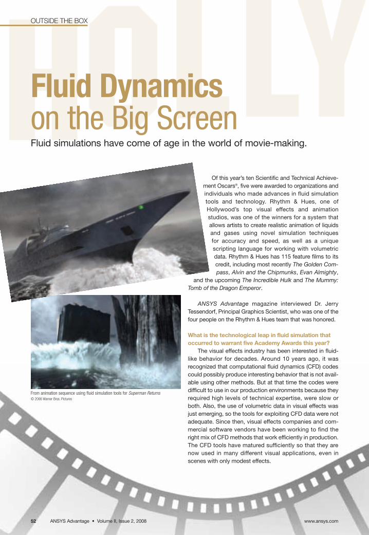
OUTSIDE THE BOX
Of this year’s ten Scientific and Technical Achieve-ment Oscars®, five were awarded to organizations andindividuals who made advances in fluid simulationtools and technology. Rhythm & Hues, one of Hollywood’s top visual effects and animation studios, was one of the winners for a system thatallows artists to create realistic animation of liquidsand gases using novel simulation techniques for accuracy and speed, as well as a unique scripting language for working with volumetricdata. Rhythm & Hues has 115 feature films to itscredit, including most recently The Golden Com-pass, Alvin and the Chipmunks, Evan Almighty,
and the upcoming The Incredible Hulk and The Mummy:Tomb of the Dragon Emperor.
ANSYS Advantage magazine interviewed Dr. JerryTessendorf, Principal Graphics Scientist, who was one of thefour people on the Rhythm & Hues team that was honored.
What is the technological leap in fluid simulation thatoccurred to warrant five Academy Awards this year?
The visual effects industry has been interested in fluid-like behavior for decades. Around 10 years ago, it wasrecognized that computational fluid dynamics (CFD) codescould possibly produce interesting behavior that is not avail-able using other methods. But at that time the codes weredifficult to use in our production environments because theyrequired high levels of technical expertise, were slow orboth. Also, the use of volumetric data in visual effects wasjust emerging, so the tools for exploiting CFD data were notadequate. Since then, visual effects companies and com-mercial software vendors have been working to find theright mix of CFD methods that work efficiently in production.The CFD tools have matured sufficiently so that they arenow used in many different visual applications, even inscenes with only modest effects.
Fluid Dynamicson the Big ScreenFluid simulations have come of age in the world of movie-making.
From animation sequence using fluid simulation tools for Superman Returns© 2006 Warner Bros. Pictures
www.ansys.comANSYS Advantage • Volume II, Issue 2, 200852
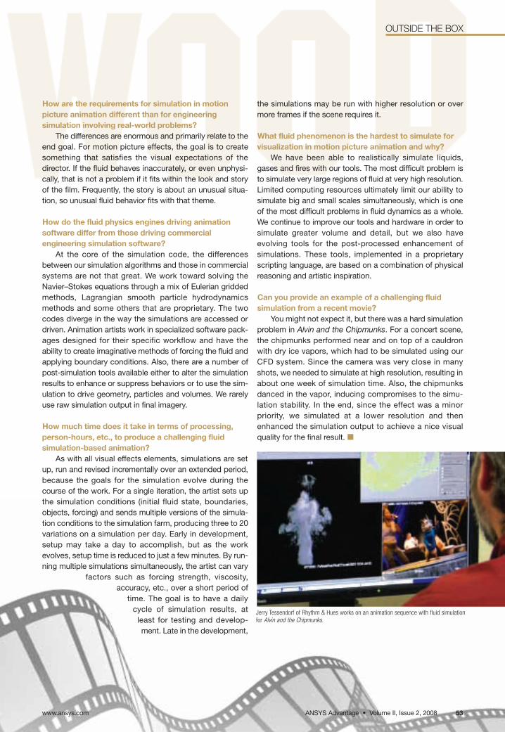
OUTSIDE THE BOX
How are the requirements for simulation in motion picture animation different than for engineering simulation involving real-world problems?
The differences are enormous and primarily relate to theend goal. For motion picture effects, the goal is to createsomething that satisfies the visual expectations of the director. If the fluid behaves inaccurately, or even unphysi-cally, that is not a problem if it fits within the look and storyof the film. Frequently, the story is about an unusual situa-tion, so unusual fluid behavior fits with that theme.
How do the fluid physics engines driving animationsoftware differ from those driving commercial engineering simulation software?
At the core of the simulation code, the differencesbetween our simulation algorithms and those in commercialsystems are not that great. We work toward solving theNavier–Stokes equations through a mix of Eulerian griddedmethods, Lagrangian smooth particle hydrodynamicsmethods and some others that are proprietary. The twocodes diverge in the way the simulations are accessed ordriven. Animation artists work in specialized software pack-ages designed for their specific workflow and have theability to create imaginative methods of forcing the fluid andapplying boundary conditions. Also, there are a number ofpost-simulation tools available either to alter the simulationresults to enhance or suppress behaviors or to use the sim-ulation to drive geometry, particles and volumes. We rarelyuse raw simulation output in final imagery.
How much time does it take in terms of processing,person-hours, etc., to produce a challenging fluid simulation-based animation?
As with all visual effects elements, simulations are setup, run and revised incrementally over an extended period,because the goals for the simulation evolve during thecourse of the work. For a single iteration, the artist sets upthe simulation conditions (initial fluid state, boundaries,objects, forcing) and sends multiple versions of the simula-tion conditions to the simulation farm, producing three to 20variations on a simulation per day. Early in development,setup may take a day to accomplish, but as the workevolves, setup time is reduced to just a few minutes. By run-ning multiple simulations simultaneously, the artist can vary
factors such as forcing strength, viscosity,accuracy, etc., over a short period of
time. The goal is to have a dailycycle of simulation results, at
least for testing and develop-ment. Late in the development,
the simulations may be run with higher resolution or overmore frames if the scene requires it.
What fluid phenomenon is the hardest to simulate forvisualization in motion picture animation and why?
We have been able to realistically simulate liquids,gases and fires with our tools. The most difficult problem isto simulate very large regions of fluid at very high resolution.Limited computing resources ultimately limit our ability tosimulate big and small scales simultaneously, which is oneof the most difficult problems in fluid dynamics as a whole.We continue to improve our tools and hardware in order tosimulate greater volume and detail, but we also have evolving tools for the post-processed enhancement of simulations. These tools, implemented in a proprietaryscripting language, are based on a combination of physicalreasoning and artistic inspiration.
Can you provide an example of a challenging fluid simulation from a recent movie?
You might not expect it, but there was a hard simulationproblem in Alvin and the Chipmunks. For a concert scene,the chipmunks performed near and on top of a cauldronwith dry ice vapors, which had to be simulated using ourCFD system. Since the camera was very close in manyshots, we needed to simulate at high resolution, resulting inabout one week of simulation time. Also, the chipmunksdanced in the vapor, inducing compromises to the simu-lation stability. In the end, since the effect was a minorpriority, we simulated at a lower resolution and thenenhanced the simulation output to achieve a nice visualquality for the final result. ■
Jerry Tessendorf of Rhythm & Hues works on an animation sequence with fluid simulationfor Alvin and the Chipmunks.
ANSYS Advantage • Volume II, Issue 2, 2008 53www.ansys.com


![[] ANSYS Advantage(Bookos.org)](https://img.pdfslide.us/doc/110x75/577cc4511a28aba71198e371/-ansys-advantagebookosorg.jpg)