Embed Size (px)
Citation preview
www.ansys.comANSYS Advantage • Volume III, Issue 1, 20094
ANSYS 12.0:Launching a New Era of Smart Engineering SimulationA full generation ahead of other solutions, ANSYS 12.0 takes product design and development to the next level. By Jim Cashman, President and CEO, ANSYS, Inc.
The current economic climate has completely changedthe way most companies view engineering simulation.Leveraging the power of virtual prototyping to compress theproduct development process and drive down costs is nolonger a choice — it’s a requirement for survival in anincreasingly competitive environment.
In nearly every industry, driving product developmentthrough engineering simulation technology has become akey strategy to develop more innovative products, reducedevelopment and manufacturing costs, and accelerate timeto market.
Backed by the unmatched power of ANSYS 12.0 software, progressive companies are taking engineering simulation a step beyond. They have already realized the enormous strategic benefits of virtual prototyping — andare now seeking more from their investments in simulation.ANSYS 12.0 enables these forward-looking companies to maximize the efficiency of their simulation processes, toincrease the accuracy of their virtual prototypes, and to capture and reuse their simulation processes and data. Thisnext level of performance signals a new era of Smart Engineering Simulation, in which product innovations can berealized more rapidly, and more cost effectively, than ever before.
There is no company better qualified to launch this newera. ANSYS has led the engineering simulation industry for nearly 40 years, revolutionizing the field of engineering
simulation in much the same way that the internet and desktoppublishing have revolutionized the broadband distribution of information. As a direct consequence of a long-standing commitment to simulation, ANSYS is the only company offering advanced simulation technologies that span all keyengineering disciplines — and bringing them together in anintegrated and flexible software platform designed specificallyto support Simulation Driven Product Development.
Over the years ANSYS has made significant technologyinvestments, acquisitions and partnership to ensure continuingleadership. We recognize that every technology breakthroughor market accomplishment has only been a stepping stone toour vision. Reflecting these investments — as well as theacquired wisdom of four decades in this industry — ANSYS12.0 represents the fullest expression of our leadership posi-tion. It is the most comprehensive engineering simulationsolution available today.
While the following pages offer a wealth of detail, I’d like tofocus on the high-level benefits that our customers will realizeas they leverage the full depth and breadth of ANSYS 12.0 tomake product development smarter, better, faster and morecollaborative than they ever thought possible.
Smart Technologies = Smart SimulationAt ANSYS, we have applied our long history of tech-
nology leadership to create the world’s smartest solution forengineering simulation — more automated, repeatable,
444 www.ansys.comANSYS Advantage • Volume III, Issue 1, 2009444
Some images courtesy FluidDA nv, Forschungszentrum Jülich GmbH,Heat Transfer Research, Inc., Riello SPA and © iStockphoto.com/iLexx.
ANSYS Advantage • Volume III, Issue 1, 2009www.ansys.com 5
persistent and intuitive than existing products. The ground-breaking ANSYS Workbench 2.0 platform is a flexibleenvironment that allows engineers to easily set up, visualizeand manage their simulations. ANSYS 12.0 offersunequalled technical breadth that allows customers toexplore a complete range of dynamic behavior, from frequency response to large overall motion of nonlinear flexible multibody systems. ANSYS has also leveraged its industry-leading capabilities to create an unequalleddepth of simulation physics, including the newly integratedANSYS FLUENT solver, advancements in all key simulationphysics, and enabling technologies for meshing, geometryand design optimization. ANSYS Engineering Knowledge Manager allows engineers to easily archive, search, retrieveand report their simulation data via a local machine or a centralized data repository. Not only does ANSYS 12.0 represent the smartest and best individual technologies, butit brings them together in a customized, scalable solutionthat meets the highly specific needs of every engineeringteam. Powerful and flexible, ANSYS 12.0 can be configuredfor advanced or professional users, deployed to a single useror enterprise, and executed on laptops or massively parallelcomputer clusters. As customer requirements grow andmature, ANSYS 12.0 is engineered to scale up accordingly.
Better Prototypes, Better Products With its unique multiphysics, high-performance
computing and complete system modeling capabilities,ANSYS 12.0 is a complete solution that takes virtual proto-typing to a new level of accuracy, realism and efficiency.ANSYS 12.0 captures the response of a completelyassembled system and assesses how a range of highly complex, real-world physical phenomena will affect not onlyindividual components but also their interactions with oneanother. Flaws in product functionality can be recognizedbefore investments are made in full-blown physical proto-types — and ideas that are validated in the virtual world canbe fast-tracked to maximize agility and capture emergingmarket opportunities. Powered by fast and accurate solvers,design optimization with ANSYS 12.0 results in prototypeswith a much higher probability of ultimate market success.
Product Design at Warp Speed ANSYS 12.0 automates many manual and tedious tasks
involved in simulation, reducing design and analysis cyclesby days or even weeks. An innovative project managementsystem allows custom simulation workflows to be created,
captured and automated with drag-and-drop ease. ANSYS12.0 amplifies the capabilities and outputs of every memberof the engineering staff, enabling them to work smarter, to intelligently make design trade-offs and to rapidly converge on the best designs. And, because ANSYS 12.0 isbased on the most advanced technology and physics,design and engineering teams can commit to manufacturingoperations with confidence — and without investing timeand money in exhaustive physical testing.
Redefining CollaborationReal-world simulation projects often involve a wide
variety of engineering personnel — and generate large volumes of data that must be shared across the enterprise.With its broad support of simulation disciplines and nativeproject management system, ANSYS 12.0 allowsengineering teams to collaborate more freely, without software barriers or other technology obstacles. Within a single project, several engineers can assess their designswithin individual disciplines, as well as easily coordinatemultiphysics simulations. The single-project environ-ment reduces redundancies and synchronization errorsamong different engineering teams. ANSYS EngineeringKnowledge Manager also provides the tools to manage the workflow of a group of engineers and a myriad of simulation projects.
At ANSYS, we have always believed that engineeringsimulation is a sound investment — and today, it is emergingas one of the smartest investments an organization canmake. We understand the incredible time and cost pressuresunder which our customers operate today, and ANSYS 12.0is specifically designed to help them meet these challenges.
In the new era of Smart Engineering Simulation heraldedby ANSYS 12.0, product development teams can workfaster and more effectively than ever before — with a greaterdegree of confidence in their finished products. Because itprovides a tremendous opportunity for engineers to designhigher-quality, more innovative products that are manu-factured faster, and at a lower cost, ANSYS 12.0 makes themost compelling case yet for engineering simulation as apowerful competitive strategy. But we are far from finished:ANSYS 12.0 is a milestone, not the destination, as we continually work to put our tools in the hands of every engineer who can benefit from them. As the power ofANSYS 12.0 is unleashed by imaginative engineering teamsaround the world, I look forward to the amazing productinnovations that will result. ■
555ANSYS Advantage • Volume III, Issue 1, 2009www.ansys.com 555
www.ansys.comANSYS Advantage • Volume III, Issue 1, 2009666 www.ansys.comwww.ansys.com66
12.0: FRAMEWORK
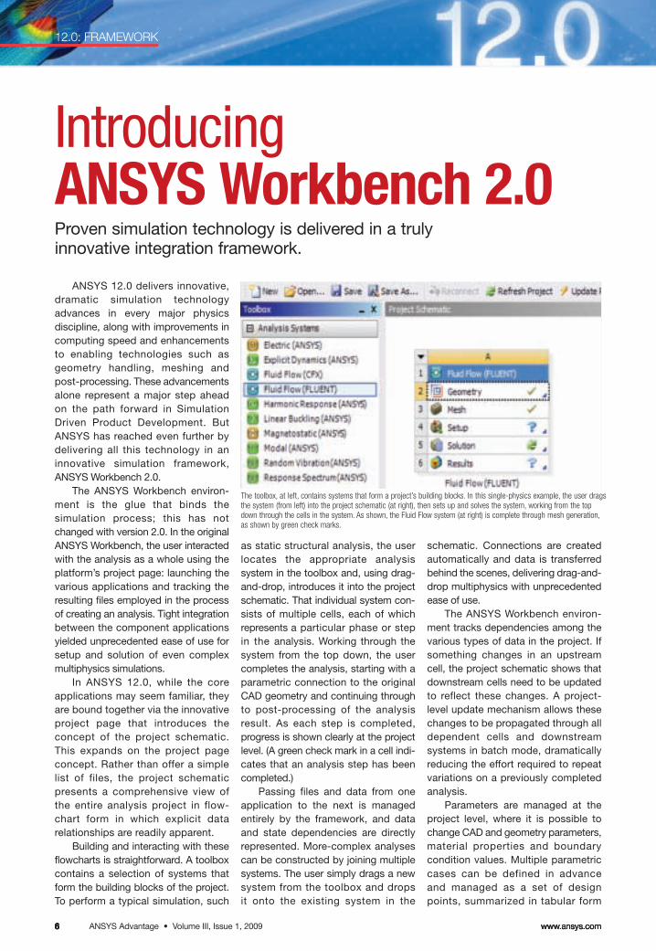
Introducing ANSYS Workbench 2.0Proven simulation technology is delivered in a truly innovative integration framework.
ANSYS 12.0 delivers innovative,dramatic simulation technologyadvances in every major physics discipline, along with improvements incomputing speed and enhancementsto enabling technologies such asgeometry handling, meshing andpost-processing. These advancementsalone represent a major step ahead on the path forward in Simulation Driven Product Development. ButANSYS has reached even further bydelivering all this technology in an innovative simulation framework,ANSYS Workbench 2.0.
The ANSYS Workbench environ-ment is the glue that binds thesimulation process; this has notchanged with version 2.0. In the originalANSYS Workbench, the user interactedwith the analysis as a whole using theplatform’s project page: launching thevarious applications and tracking theresulting files employed in the processof creating an analysis. Tight integrationbetween the component applicationsyielded unprecedented ease of use forsetup and solution of even complexmultiphysics simulations.
In ANSYS 12.0, while the coreapplications may seem familiar, theyare bound together via the innovativeproject page that introduces the concept of the project schematic.This expands on the project pageconcept. Rather than offer a simplelist of files, the project schematicpresents a comprehensive view ofthe entire analysis project in flow-chart form in which explicit datarelationships are readily apparent.
Building and interacting with theseflowcharts is straightforward. A toolboxcontains a selection of systems thatform the building blocks of the project.To perform a typical simulation, such
as static structural analysis, the userlocates the appropriate analysis system in the toolbox and, using drag-and-drop, introduces it into the projectschematic. That individual system con-sists of multiple cells, each of whichrepresents a particular phase or stepin the analysis. Working through thesystem from the top down, the usercompletes the analysis, starting with aparametric connection to the originalCAD geometry and continuing throughto post-processing of the analysisresult. As each step is completed,progress is shown clearly at the projectlevel. (A green check mark in a cell indi-cates that an analysis step has beencompleted.)
Passing files and data from oneapplication to the next is managedentirely by the framework, and data and state dependencies are directlyrepresented. More-complex analysescan be constructed by joining multiplesystems. The user simply drags a newsystem from the toolbox and drops it onto the existing system in the
schematic. Connections are createdautomatically and data is transferredbehind the scenes, delivering drag-and-drop multiphysics with unprecedentedease of use.
The ANSYS Workbench environ-ment tracks dependencies among thevarious types of data in the project. Ifsomething changes in an upstreamcell, the project schematic shows thatdownstream cells need to be updatedto reflect these changes. A project-level update mechanism allows thesechanges to be propagated through alldependent cells and downstream systems in batch mode, dramaticallyreducing the effort required to repeatvariations on a previously completedanalysis.
Parameters are managed at theproject level, where it is possible tochange CAD and geometry parameters,material properties and boundary condition values. Multiple parametriccases can be defined in advanceand managed as a set of designpoints, summarized in tabular form
The toolbox, at left, contains systems that form a project’s building blocks. In this single-physics example, the user dragsthe system (from left) into the project schematic (at right), then sets up and solves the system, working from the topdown through the cells in the system. As shown, the Fluid Flow system (at right) is complete through mesh generation,as shown by green check marks.
ANSYS Advantage • Volume III, Issue 1, 2009www.ansys.com 7
12.0: FRAMEWORK
on the ANSYS Workbench project page.Design Exploration systems can beconnected to these same project-levelparameters to drive automated designinvestigations, such as Design of Experi-ments, goal-driven optimization or Designfor Six Sigma.
In addition to serving as a frameworkfor the integration of existing applications,the ANSYS Workbench 2.0 platform alsoserves as an application developmentframework and will ultimately provide project-wide scripting, reporting, a userinterface (UI) toolkit and standard datainterfaces. These capabilities will emergeover this and subsequent releases. AtANSYS 12.0, Engineering Data andANSYS DesignXplorer are no longerindependent applications: They have beenre-engineered using the UI toolkit and integrated within the ANSYS Workbenchproject window.
Beyond managing individual simu-lation projects, ANSYS Workbenchinterfaces with the ANSYS EngineeringKnowledge Manager (EKM) product for simulation process and data management. At ANSYS 12.0, ANSYSWorkbench includes the single-userconfiguration of ANSYS EKM, calledANSYS EKM Desktop. (See sidebar.)
ANSYS Workbench 2.0 represents asizable step forward in engineering simu-lation. Within this innovative softwareframework, analysts can leverage a complete range of proven simulationtechnology, including common tools forCAD integration, geometry repair andmeshing. A novel project schematic concept guides users through complexanalyses, illustrating explicit data relationships and capturing the processfor automating subsequent analyses.Meanwhile, its parametric and persistentmodeling environment in conjunctionwith integral tools for design optimizationand statistical studies enable engineersto arrive at the best design faster. Looking beyond ANSYS 12.0, theANSYS Workbench platform will befurther refined: The aim is to deliver acomprehensive set of simulation tech-nology in an open, adaptive softwarearchitecture that allows for pervasivecustomization and the integration ofthird-party applications. ■
Judd Kaiser, Shantanu Bhide, Scott Gilmore and ToddMcDevitt of ANSYS, Inc. contributed to this article.
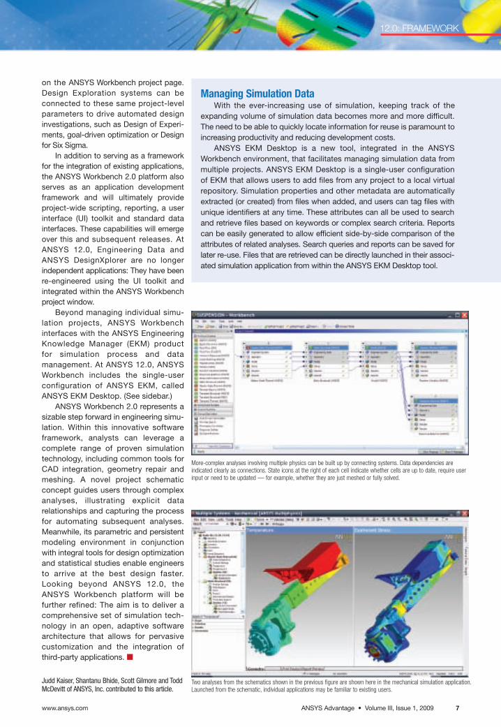
Managing Simulation Data With the ever-increasing use of simulation, keeping track of the
expanding volume of simulation data becomes more and more difficult.The need to be able to quickly locate information for reuse is paramount toincreasing productivity and reducing development costs.
ANSYS EKM Desktop is a new tool, integrated in the ANSYS Workbench environment, that facilitates managing simulation data frommultiple projects. ANSYS EKM Desktop is a single-user configuration of EKM that allows users to add files from any project to a local virtualrepository. Simulation properties and other metadata are automaticallyextracted (or created) from files when added, and users can tag files withunique identifiers at any time. These attributes can all be used to searchand retrieve files based on keywords or complex search criteria. Reportscan be easily generated to allow efficient side-by-side comparison of theattributes of related analyses. Search queries and reports can be saved forlater re-use. Files that are retrieved can be directly launched in their associ-ated simulation application from within the ANSYS EKM Desktop tool.
More-complex analyses involving multiple physics can be built up by connecting systems. Data dependencies are indicated clearly as connections. State icons at the right of each cell indicate whether cells are up to date, require userinput or need to be updated — for example, whether they are just meshed or fully solved.
Two analyses from the schematics shown in the previous figure are shown here in the mechanical simulation application.Launched from the schematic, individual applications may be familiar to existing users.
www.ansys.comANSYS Advantage • Volume III, Issue 1, 2009888
12.0: GEOMETRY AND MESHING
Taking Shape in 12.0ANSYS combines depth of simulationwith industry experience to providegeometry and meshing tools that realizesimulation results faster.
Engineering simulation softwareusers have been known to spend up to90 percent of their simulation-relatedtime working on pre-processing tasks.By targeting developments in capabilitiesto increase ease of use, simplifying pre-processing tasks, and increasing thecapabilities of pre-processing tools,ANSYS has systematically deliveredexciting advances to increase the efficiency of simulation.
ANSYS has combined rich geometry and meshing techniques with its depth of knowledge andexperience, and the end result isproducts capable of harnessing integrated geometry and meshingsolutions that share core librarieswith other applications. At releases10.0 and 11.0, ANSYS introducedrobust, new meshing capabilitiesfrom ANSYS ICEM CFD and ANSYS
CFX tools into the ANSYS meshing platform — which provides the foundationfor unifying and leveraging meshing tech-nologies, making them interoperable andavailable in multiple applications. Takingadvantage of the enhanced ANSYS Workbench 2.0 framework, the companyprovides further significant improve-ments for ANSYS 12.0 geometry andmeshing applications.
CAD ConnectionsANSYS continues to deliver a leading
CAD-neutral CAE integration environ-ment, providing direct, associative andbi-directional interfaces with all majorCAD systems, including Unigraphics®,Autodesk® Inventor®, Pro/ENGINEER®,CATIA® V5, PTC CoCreate® Modeling,SolidEdge®, SolidWorks®, and Autodesk®
Mechanical Desktop®. Software fromANSYS also supports file-based readers
for IGES, STEP, ACIS®, Parasolid®,CATIA® V4 and CATIA V5. At ANSYS12.0, geometry interfaces have beenenhanced to import more informationfrom CAD systems, including new datatypes such as line bodies for modelingbeams, additional attributes such ascolors and coordinate systems, andimproved support for named selectionscreated within the CAD systems.
For pre-processing larger models,release 12.0 includes support for 64-bitoperating systems, and smart andselective updates of CAD parts. Thenewly introduced ability to selectivelyupdate CAD components allows usersto update individual parts instead of anentire assembly, thus making geometryupdates much faster and more targeted.
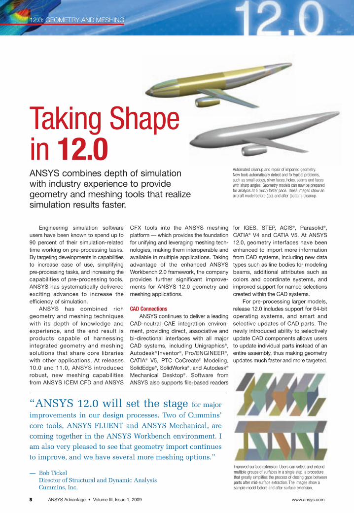
Automated cleanup and repair of imported geometry:New tools automatically detect and fix typical problems,such as small edges, sliver faces, holes, seams and faceswith sharp angles. Geometry models can now be preparedfor analysis at a much faster pace. These images show anaircraft model before (top) and after (bottom) cleanup.
“ANSYS 12.0 will set the stage for majorimprovements in our design processes. Two of Cummins’core tools, ANSYS FLUENT and ANSYS Mechanical, arecoming together in the ANSYS Workbench environment. Iam also very pleased to see that geometry import continuesto improve, and we have several more meshing options.”
— Bob Tickel Director of Structural and Dynamic AnalysisCummins, Inc.
Improved surface extension: Users can select and extendmultiple groups of surfaces in a single step, a procedurethat greatly simplifies the process of closing gaps betweenparts after mid-surface extraction. The images show asample model before and after surface extension.
ANSYS Advantage • Volume III, Issue 1, 2009www.ansys.com 9999www.ansys.com 9
12.0: GEOMETRY AND MESHING
Geometry Handling in ANSYS DesignModeler
Geometry modeling in the ANSYSWorkbench environment is greatlyimproved to provide increasedautomation, greater flexibility andimproved ease of use for the task ofpreparing geometry for analysis. Thefeature-based, parametric ANSYSDesignModeler tool, which can be usedto create parametric geometry fromscratch or to prepare an existing CADgeometry for analysis, now includesautomated options for simplification,cleanup, repair and defeaturing.
Merge, Connect and Projectfeatures have been added for improvedsurface modeling in ANSYS 12.0. Faceand Edge merge operations can beused to easily simplify models by eliminating unnecessary features andboundaries, leading to improved meshand solution quality. The Connectoperation can be applied to ensureproper connectivity in models with gapsand overlaps.
Automated cleanup and repaircapabilities have been improved in the12.0 release. New tools automaticallydetect and fix typical problems, such assmall edges, sliver faces, holes, seamsand faces with sharp angles. Geometrymodels can now be prepared for analy-sis at a much faster pace. As always,analysis settings remain persistent afterperforming these operations and areupdated automatically in response tochanges in geometry.
Shell modeling has been enhancedin several ways, including improvedsurface extensions. The ability to selectand extend groups of surfaces greatlysimplifies the process of closing gapsbetween parts after mid-surface extrac-tion. The result is easier modeling ofwelds, for example.
Analysis-specific tools within theANSYS DesignModeler product nowinclude an automated option to extractflow volumes for fluid dynamics analy-ses. In addition, several new features,including user-defined offsets, user-defined cross sections and betterorientation controls, are available forimproved beam modeling for structuralanalyses.
Improved attribute support is available with ANSYS DesignModeler12.0. This includes options to createattributes within ANSYS DesignModeleras well as to import additional attributesfrom external CAD, including namedselections, coordinate systems andwork points.
ANSYS Meshing PlatformA primary focus for ANSYS 12.0 has
been to provide an automated meshingsolution that is best in class for fluiddynamics. With the addition of cap-abilities from GAMBIT and TGridmeshing applications, major improve-ments have been made in the automaticgeneration of CFD-appropriate tetra-hedral meshes with minimal user input.Advanced size functions (similar to thosefound in GAMBIT), prism/tet meshing(from TGrid) and other ANSYS meshingtechnologies combine to provideimproved smoothness, quality, speed,curvature and proximity featurecapturing, and boundary layer capturing.
In the area of hex meshing, the tra-ditional sweep and thin sweep methodshave seen evolutionary improvements.A new method called MultiZone hasbeen integrated into the ANSYS meshing platform. By combining existing ANSYS ICEM CFD Hexatechnology with improvements inautomation, MultiZone allows the userto automatically create hex meshes formany complex geometries withoutrequiring geometry decomposition.
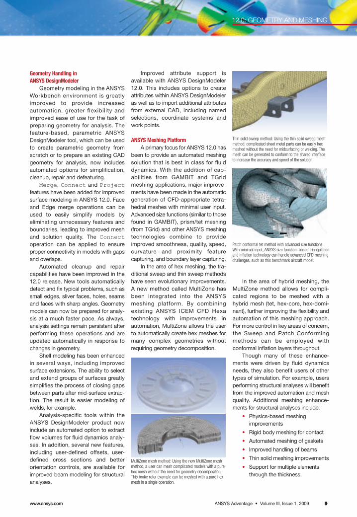
Thin solid sweep method: Using the thin solid sweep meshmethod, complicated sheet metal parts can be easily hexmeshed without the need for midsurfacing or welding. Themesh can be generated to conform to the shared interfaceto increase the accuracy and speed of the solution.
MultiZone mesh method: Using the new MultiZone meshmethod, a user can mesh complicated models with a purehex mesh without the need for geometry decomposition.This brake rotor example can be meshed with a pure hexmesh in a single operation.
Patch conformal tet method with advanced size functions:With minimal input, ANSYS size function–based triangulation and inflation technology can handle advanced CFD meshing challenges, such as this benchmark aircraft model.
In the area of hybrid meshing, theMultiZone method allows for compli-cated regions to be meshed with ahybrid mesh (tet, hex-core, hex-domi-nant), further improving the flexibility andautomation of this meshing approach.For more control in key areas of concern,the Sweep and Patch Conforming methods can be employed with conformal inflation layers throughout.
Though many of these enhance-ments were driven by fluid dynamicsneeds, they also benefit users of othertypes of simulation. For example, usersperforming structural analyses will benefitfrom the improved automation and meshquality. Additional meshing enhance-ments for structural analyses include:
• Physics-based meshing improvements
• Rigid body meshing for contact
• Automated meshing of gaskets
• Improved handling of beams
• Thin solid meshing improvements
• Support for multiple elementsthrough the thickness
www.ansys.comANSYS Advantage • Volume III, Issue 1, 20091010101010
12.0: GEOMETRY AND MESHING
Enhancements toTurbomachinery Tools
With release 12.0, a number ofenhancements have been incorpo-rated into ANSYS BladeModeler,the design tool tailored to bladedgeometries for rotating machinery.Within the BladeGen component,the integrated tools for determininginitial blade shape and size (whichwere developed in conjunction withpartner PCA Engineers Limited)have been expanded to cover cen-trifugal compressors and axial fansin addition to radial turbines andcentrifugal pumps. The other com-ponent of ANSYS BladeModeler,BladeEditor, includes new bladegeometry modeling capabilities tocreate and modify one or more bladed components. As an add-in toANSYS DesignModeler, ANSYSBladeModeler provides access toANSYS DesignModeler’s extensivefunctionality to create non-standard geometry componentsand features.
ANSYS TurboGrid softwareincludes a number of evolutionaryimprovements in release 12.0, andintroduces a completely newmeshing technology. This toolfully automates a series of top-ology and smoothing steps tolargely eliminate the need tomanually adjust mesh controls,yet still generates high-qualityfluid dynamics meshes for bladedturbomachinery components.
• Generation of conformal meshesin multi-body parts
• Enhanced and new mesh controls
• Pinch features to help in defeaturing models
• Improved smoothing
• Improved flexibility in size controls and mesh refinement
• Arbitrary mesh matching toimprove node linking and solver accuracy
These improvements, though drivenby structural analysis needs, providebenefits to the entire spectrum ofANSYS users.
ANSYS ICEM CFDFor ANSYS 12.0, ANSYS ICEM CFD
meshing development focused on twoprimary tasks: improved implement-ation of ANSYS ICEM CFD meshing
technology within the ANSYS meshingplatform and continued development toenhance the ANSYS ICEM CFD productfor interactive meshing customers.Because the ANSYS ICEM CFD integra-tion involves the sharing of corelibraries, improvements made for theANSYS meshing platform also enhancethe ANSYS ICEM CFD meshing product(and vice versa).
MultiZone meshing is an example of a crossover technology that hasreceived special attention in bothANSYS meshing and the stand-aloneANSYS ICEM CFD meshing product.This hybrid meshing method combinesthe strengths of various meshers, suchas ANSYS ICEM CFD Hexa and TGrid,in a semi-automatic blocking frame-work. Within the ANSYS Workbenchenvironment, multizone automation provides multi-source, multi-targetand multi-direction sweep capabilities reminiscent of the GAMBIT Cooper tool.In the stand-alone ANSYS ICEM CFDproduct, this is an excellent way tomesh for external aerodynamics in asemi-automated way that providesrapid hybrid meshing with a high degreeof control and quality.
Improvements for ANSYS ICEMCFD 12.0 include process and interfacestreamlining, new hexa features, BFCartmesher enhancements, mesh editingadvancements, output format updatesand more. ■
Ben Klinkhammer, Shyam Kishor, Erling Eklund,Simon Pereira and Scott Gilmore of ANSYS, Inc.contributed to this article.
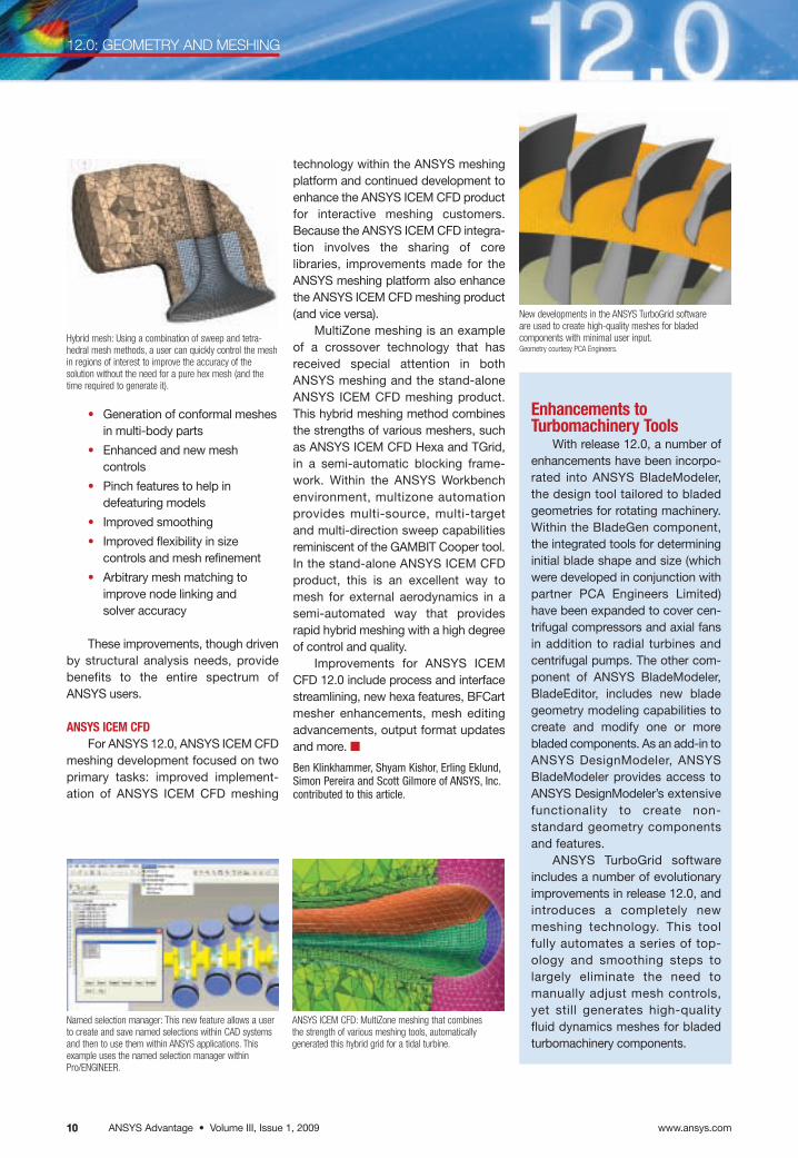
Hybrid mesh: Using a combination of sweep and tetra-hedral mesh methods, a user can quickly control the meshin regions of interest to improve the accuracy of the solution without the need for a pure hex mesh (and thetime required to generate it).
New developments in the ANSYS TurboGrid softwareare used to create high-quality meshes for bladedcomponents with minimal user input.Geometry courtesy PCA Engineers.
Named selection manager: This new feature allows a userto create and save named selections within CAD systemsand then to use them within ANSYS applications. Thisexample uses the named selection manager withinPro/ENGINEER.
ANSYS ICEM CFD: MultiZone meshing that combinesthe strength of various meshing tools, automaticallygenerated this hybrid grid for a tidal turbine.
ANSYS Advantage • Volume III, Issue 1, 2009www.ansys.com 11111111
Continuing to build on the foundation of prior releases,ANSYS 12.0 expands the company’s industry-leading comprehensive multiphysics solutions. New features andenhancements are available for solving both direct andsequentially coupled multiphysics problems, and theANSYS Workbench framework makes performing multi-physics simulations even faster than before.
ANSYS Workbench IntegrationThe integration of the broad array of ANSYS solver
technologies has taken a considerable step forward withrelease 12.0. The ANSYS Workbench environment has beenredesigned for an efficient multiphysics workflow by inte-grating the solver technology into one unified simulationenvironment. This platform now includes drag-and-dropmultiphysics, which allows the user to easily set up andvisualize multiphysics analysis, significantly reducing thetime necessary to obtain solutions to complex multiphysicsproblems.
Another new enhancement to the ANSYS Workbenchframework is the support for steady-state electric conduc-tion. There is a new analysis system that exposes 3-D solidelectric conduction elements (SOLID231 and SOLID232) inthe ANSYS Workbench platform. All the benefits of thispopular environment — leveraging CAD data, meshingcomplex geometry and design optimization features — arenow available for electric conduction analysis.
Also new in ANSYS Workbench at version 12.0 is sup-port for direct coupled-field analysis. Relevant elements(SOLID226 and SOLID227) are now natively supported in the ANSYS Workbench platform for thermal–electric coupling. There also is a new analysis system for thermal–electric coupling that supports Joule heating problems with
12.0: MULTIPHYSICS
Multiphysicsfor the Real WorldIn ANSYS 12.0, multiphysics capabilities continue toincrease in flexibility, application and ease of use.
temperature-dependent material properties and advancedthermoelectric effects, including Peltier and Seebeck effects.The applications for this new technology include Joule heating of integrated circuits and electronic traces,busbars, and thermoelectric coolers and generators.
Solver PerformanceANSYS 12.0 extends the distributed sparse solver to
support unsymmetric and complex matrices for both sharedand distributed memory parallel environments. This newsolver technology dramatically reduces the time needed toperform certain direct coupled solutions including Peltier andSeebeck effects as well as thermoelasticity. Thermo-elasticity, including thermoelastic damping, is an importantloss mechanism for many MEMS devices, such as block resonators and silicon ring gyroscopes.
ElementsA new family of direct coupled-
field elements is available in ANSYS12.0; these new elements enable themodeling of fluid flow through aporous media. This exciting newcapability, comprising coupledpore–pressure mechanical solids,
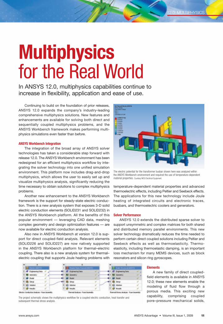
The project schematic shows the multiphysics workflow for a coupled electric conduction, heat transfer andsubsequent thermal stress analysis.
The electric potential for the transformer busbar shown here was analyzed within the ANSYS Workbench environment and required the use of temperature-dependentmaterial properties. Courtesy WEG Electrical Equipment.
www.ansys.comANSYS Advantage • Volume III, Issue 1, 200912
Coupling Electromagnetics
By joining forces with Ansoft, ANSYS can delivergreater multiphysics capabilities — specifically electro-magnetics — to the ANSYS suite. The plan to integrate thiselectromagnetics technology within the existing ANSYS
simulation environment started almost immediately afterthe acquisition. While the combined development team isworking toward a seamlessly integrated bidirectional solution, several electromagnetic-centric case studies
already have demonstrated the abilityto couple electromagnetic, thermaland structural tools within theadaptive architecture of the ANSYSWorkbench environment.
For example, a high-power elec-tronic connector used in a radarapplication to connect a transmitter toan antenna must be engineered fromelectromagnetic, thermal and structuralperspectives to ensure success. Thesimulation was performed by couplingAnsoft’s HFSS software with theANSYS Workbench environment, usingadvanced thermal and structural capa-bilities. Engineers used HFSS to ensurethat the device was transmitting in the
12.0 MULTIPHYSICS
enables multiphysics modelingof new classes of civil and biomed-ical engineering problems that relyon fluid pore pressures. The elementsallow users to model fluid pore pres-sures in soils (for simulating building foundations)and biometric materials (for modeling bone in order todevelop prosthetic implants).
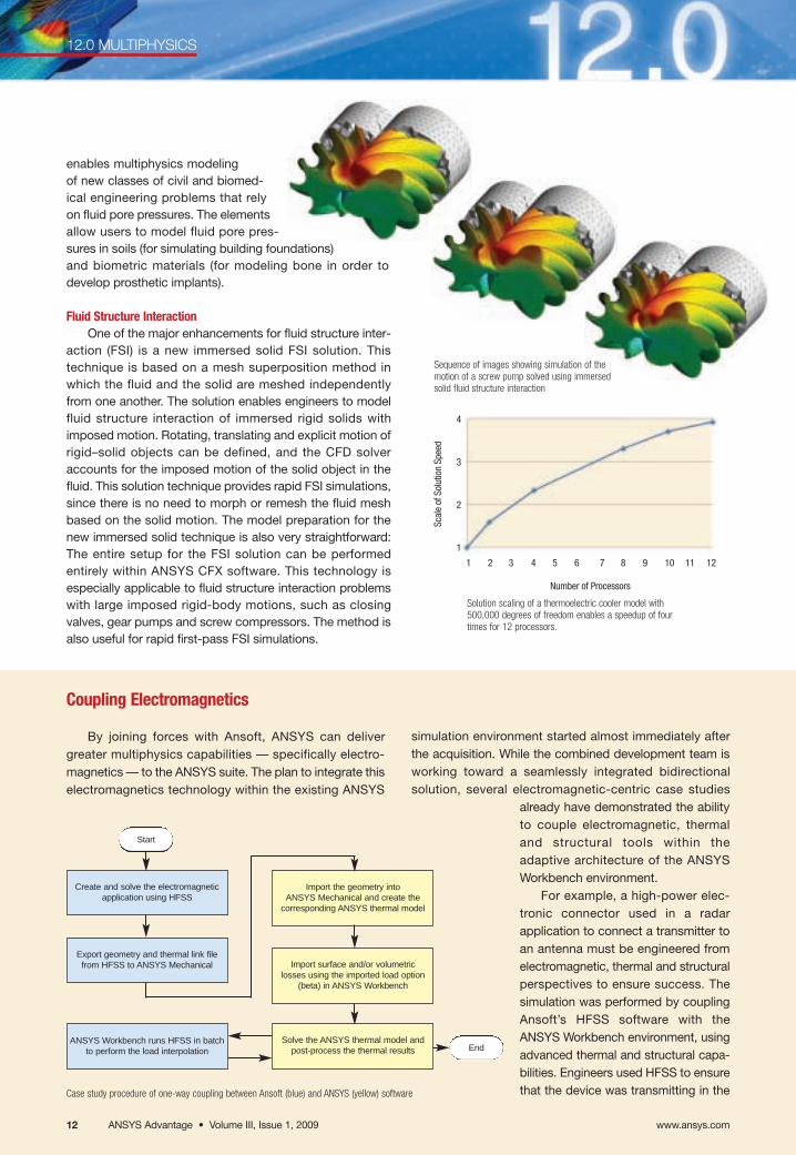
Fluid Structure InteractionOne of the major enhancements for fluid structure inter-
action (FSI) is a new immersed solid FSI solution. Thistechnique is based on a mesh superposition method inwhich the fluid and the solid are meshed independentlyfrom one another. The solution enables engineers to modelfluid structure interaction of immersed rigid solids withimposed motion. Rotating, translating and explicit motion ofrigid–solid objects can be defined, and the CFD solveraccounts for the imposed motion of the solid object in thefluid. This solution technique provides rapid FSI simulations,since there is no need to morph or remesh the fluid meshbased on the solid motion. The model preparation for thenew immersed solid technique is also very straightforward:The entire setup for the FSI solution can be performedentirely within ANSYS CFX software. This technology isespecially applicable to fluid structure interaction problemswith large imposed rigid-body motions, such as closingvalves, gear pumps and screw compressors. The method isalso useful for rapid first-pass FSI simulations.
Solution scaling of a thermoelectric cooler model with 500,000 degrees of freedom enables a speedup of four times for 12 processors.
Case study procedure of one-way coupling between Ansoft (blue) and ANSYS (yellow) software
Start
End
Create and solve the electromagneticapplication using HFSS
ANSYS Workbench runs HFSS in batchto perform the load interpolation
Export geometry and thermal link filefrom HFSS to ANSYS Mechanical Import surface and/or volumetric
losses using the imported load option(beta) in ANSYS Workbench
Import the geometry into ANSYS Mechanical and create the
corresponding ANSYS thermal model
Solve the ANSYS thermal model andpost-process the thermal results
4
3
2
1
Scal
e of
Sol
utio
n Sp
eed
1 2 3 4 5 6 7 8 9 10 11 12
Number of Processors
Sequence of images showing simulation of themotion of a screw pump solved using immersedsolid fluid structure interaction
ANSYS Advantage • Volume III, Issue 1, 2009 13
12.0: MULTIPHYSICS
Another new capability for fluid structure interaction inANSYS 12.0, FLUID136 now solves the nonlinear Reynoldssqueeze film equations for nonlinear transient FSI applica-tions involving thin fluid films. Since the nonlinear fluidic andstructural responses are coupled at the finite element level,the solution is very fast and robust for thin fluid film applica-tions. Any squeeze film application can benefit from thistechnology, including thin film fluid damping often found inRF MEMS switches.
Version 12.0 offers another exciting new FSI capability:the ability to perform one-way fluid structure interactionusing ANSYS FLUENT software as the CFD solver. This capability enables one-way load transfer for surface
temperatures or surface forces between ANSYS FLUENTand ANSYS mechanical products based on ANSYS CFX-Post. The most appropriate applications include those thatrequire one-way transfer of fluid pressures or temperaturesfrom CFD to a mechanical analysis, such as automotiveexhaust manifolds, heat sinks for electronics cooling andturbomachinery.
Multi-Field SolverThe multi-field solver (used for performing implicit
sequential coupling) contains a number of new enhance-ments at release 12.0. The first is a new solution option thatcontrols writing a multiframe restart file. This capabilityallows a user to restart an analysis from any multi-field timestep, which allows for better control over the availability of arestart file with less hard drive usage. Another enhancementis more-flexible results file controls. This capability reducesthe results file sizes for the multi-field solver, and it allows forsynchronizing the fluid and mechanical results in an FSIsolution. The final improvement is new convergence con-trols for the multi-field solution to provide more flexiblesolution controls for nonlinear convergence of the multi-fieldsolver. The applications for these enhancements are anymultiphysics application using sequential coupling includingfluid structure interaction. ■
Stephen Scampoli of ANSYS, Inc. and Ansoft LLC technical specialists contributed to this article.
The results of an RF MEMS switch solved by coupling the electrostatic, fluid andmechanical behavior of the switch in one analysis using FLUID136 to represent squeezefilm effects. Image courtesy EPCOS NL and Philips Applied Technologies.
Deformation of the high-power electronic connector can be predicted by combiningAnsoft HFSS and ANSYS Mechanical software.
solenoid. The power loss was used as an input for a thermalsimulation performed with ANSYS Mechanical software todetermine the temperature profile of the device. Subse-quently, the application predicted how the device deformeddue to the rise in temperature. Such coupling delivers a powerful analysis framework needed to solve these complex,interrelated physics problems. Thus, engineers canaddress electro-thermal-stress problems associated withoptimizing state-of-the-art radio frequency (RF) and electro-mechanical components including antennas, actuators,power converters and printed circuit boards (PCBs).
proper path, by calculating the high-frequency electro-magnetic fields, power loss density distribution and S-parameters. In such high-power applications, it is criticalto determine the temperature distribution to ensure thedevice stays below temperatures that cause material failure,such as melting. The power loss density results from the
HFSS simulation were used as the source for the thermal simulation performed withinANSYS Mechanical software,which simulated the tempera-ture distribution of the device.
In another case, a valve-actuating solenoid applicationused a coupled ANSYS andAnsoft simulation to analyzetemperature distribution.Maxwell software was used tocalculate the power loss fromthe low-frequency electro-magnetic fields within the
Eddy current and conduction loss calculated by Ansoft’s Maxwell software
www.ansys.comANSYS Advantage • Volume III, Issue 1, 20091414 www.ansys.com14
12.0: ELECTROMAGNETICS
ANSYS Emag 12.0Generates SolutionsImproved accuracy, speed and platform integration advancethe capabilities of low-frequency electromagnetic simulation.
As the combined development teams from Ansoft andANSYS set out to integrate the world-class Ansoft electronicdesign products into the ANSYS portfolio, ANSYScustomers can benefit immediately from improved andextended electromagnetics capabilities in release 12.0.
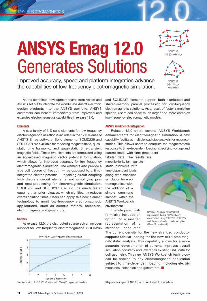
ElementsA new family of 3-D solid elements for low-frequency
electromagnetic simulation is included in the 12.0 release ofANSYS Emag software. Solid elements (SOLID236 andSOLID237) are available for modeling magnetostatic, quasi-static time harmonic, and quasi-static time-transientmagnetic fields. These two elements are formulated usingan edge-based magnetic vector potential formulation,which allows for improved accuracy for low-frequency electromagnetic simulation. The elements also provide atrue volt degree of freedom — as opposed to a time-integrated electric potential — enabling circuit couplingwith discrete circuit elements and simplifying pre- and post-processing for electromagnetic simulation.SOLID236 and SOLID237 also include much fastergauging than prior releases, which significantly reducesoverall solution times. Users can apply this new elementtechnology to most low-frequency electromagneticapplications, such as electric motors, solenoids, electromagnets and generators.
SolversAt release 12.0, the distributed sparse solver includes
support for low-frequency electromagnetics. SOLID236
and SOLID237 elements support both distributed andshared-memory parallel processing for low-frequency electromagnetic solutions. As a result of faster simulationspeeds, users can solve much larger and more complexlow-frequency electromagnetic models.
ANSYS Workbench IntegrationRelease 12.0 offers several ANSYS Workbench
enhancements for electromagnetic simulation. A newcapability facilitates multiple load step analysis for magneto-statics. This allows users to compute the magnetostaticresponse to time-dependent loading, specifying voltage andcurrent loads with time-dependenttabular data. The results aremore flexibility for magneto-static problems withtime-dependent loadsalong with transientsimulation for elec-tromagnetics, withthe addition of asimple commandsnippet, within theANSYS Workbenchenvironment.
The integrated plat-form also includes anoption for a meshed representation of astranded conductor.The current density for the new stranded conductor supports tabular loading for the new multi-step mag-netostatic analysis. This capability allows for a moreaccurate representation of current, improves overall simulation accuracy and leverages existing CAD data forcoil geometry. This new ANSYS Workbench technologycan be applied to any electromagnetic application subject to time-dependent loading, including electricmachines, solenoids and generators. ■
Stephen Scampoli of ANSYS, Inc. contributied to this article.Solution scaling of a SOLID237 model with 550,000 degrees of freedom
5
4
3
2
1
DANSYS for Low-Frequency Electromagnetics
Solu
tions
Spe
edup
Number of Processors1 2 3 4 5 6 7 8
SOLID2363-D 20-node brick
SOLID2373-D 10-node tetrahedron
Nonlinear transient rotational test rig solved in the ANSYS Workbench environment using SOLID236, SOLID237and the new stranded conductor option(TEAM24 benchmark)
ANSYS Advantage • Volume III, Issue 1, 2009www.ansys.com 1515www.ansys.com 15
12.0: FLUIDS
With release 12.0, ANSYS con-tinues to deliver on its commitment todevelop the world’s most advancedfluid dynamics technology and makeit easier and more efficient to use.Through its use, engineers can develop the most competitive prod-ucts and manufacturing processes possible. In addition to deliveringnumerous new advancements inphysics, numerics and performance,ANSYS has combined the function-ality of both ANSYS CFX and ANSYSFLUENT into the ANSYS Workbenchplatform. Customers can use thisintegrated environment to leveragesimulation technology, includingsuperior CAD connectivity, geometrycreation and repair, and advancedmeshing, all engineered to improvesimulation efficiency and compressthe overall design and analysis cycle.
Integration into ANSYS Workbench ANSYS 12.0 introduces the full
integration of its fluids products intoANSYS Workbench together with thecapability to manage simulation workflows within the environment. Thisallows users — whether they employANSYS CFX or ANSYS FLUENT soft-ware (or both) — to create, connectand re-use systems; perform auto-mated parametric analyses; andseamlessly manage simulationsusing multiple physics all within one environment.
The integration of the core CFDproducts into the ANSYS Workbenchenvironment also provides users with
access to bidirectional CADconnections, powerful geometrymodeling and advanced mesh genera-tion. (See the article Taking Shape in12.0.) Users can examine analysisresults in full detail using CFD-Post,also available within the ANSYS Workbench environment.
MultiphysicsIn some cases, fluid simulations
must consider physics beyond basicfluid flow. Both ANSYS CFX andANSYS FLUENT technologies providemany multiphysics simulation optionsand approaches, including coupling to ANSYS Mechanical software to analyze fluid structure interaction (FSI) within the ANSYS Workbenchenvironment.
Another new capability is theimmersed solid technique in ANSYSCFX 12.0 that allows users to includethe effects of large solid motion in their analyses. (See the article Multiphysics for the Real World.)
General Solver ImprovementsANSYS continues to make
progress on basic core solver speed, abenefit to all users for all types of appli-cations, steady or transient. A suite ofcases that span the range of industrialapplications has consistently shownincreases in solver speed of 10 to 20percent, or even more, for both ANSYSCFX and ANSYS FLUENT software.Beyond core solver efficiency, improve-ments to various aspects of parallelefficiency address the continued
A Flood of FluidsDevelopmentsA new integrated environment and technology enhancements make fluidssimulation faster, more intuitive andmore accurate.
growth and needs of high-performancecomputing. (See the article The Needfor Speed.)
The perennial goal of improvingaccuracy without sacrificing robustnessmotivated numerous developments,including new discretization optionssuch as the bounded second-orderoption in ANSYS FLUENT and theiteratively-bounded high-resolutiondiscretization scheme in ANSYS CFX.Being able to consistently use higher-order discretization schemes meansthat users will see further increases inthe accuracy of flow simulations withoutpenalties in robustness.
User Interface Ease of use has been enhanced in
various ways. Most noticeably, theANSYS FLUENT user interface hastaken a significant step forward byadopting a single-window interfaceparadigm, consistent with otherapplications integrated in ANSYSWorkbench. A new navigation paneand icon bar and new task pages andtools for graphics window manage-ment all reflect a more modern andintuitive interface while providingaccess to the previous version’s menubar and text user interface.
Fuel injector model with close-up of vapor volume fraction contours at the injector surface
www.ansys.comANSYS Advantage • Volume III, Issue 1, 200916
12.0: FLUIDS
16
Multiphase Multiphase flow modeling con-
tinues to receive a great deal ofdevelopment attention, in terms ofnumerics and robustness improve-ments as well as extended modelingcapabilities. ANSYS FLUENT softwareextends the single-phase couplingtechnology, introduced previously forthe pressure-based solver, to includeEulerian multiphase simulations. Thisenhancement provides more robustconvergence, especially for steady-state flows. ANSYS CFX users will findthat improvements to the option toinclude solution of the volume fractionequations as part of the coupled set ofequations make it more broadly usablein applications with separate velocityfields for each phase. Other modelingenhancements include the implemen-tation of a wall boiling model andadditional non-drag forces in ANSYSCFX as well as more robust cavitationand immiscible fluid models in ANSYSFLUENT.
Turbomachinery The significant proportion of cus-
tomers using products from ANSYS forthe design and optimization of rotatingmachinery ensured that this fieldreceived a substantial developmentfocus. This latest release contains avariety of enhancements to core solvertechnology that couple rotating andstationary components more robustly,more accurately and more efficiently.ANSYS BladeModeler and ANSYSTurboGrid, specialized products for
bladed geometry design and mesh gen-eration, continue to evolve and improve.(See the Geometry and Meshing articlefor more details.)
An exciting new development for turbo-machinery analysts is the introduction of the through-flow code ANSYS Vista™ TF.Developed together with partner PCA Engineers Limited, Vista TF complementsfull 3-D fluid dynamics analysis to providebasic performance predictions on one ormore bladed components in a matter ofseconds, allowing users to quickly and easily screen initial designs.
And More … These enhancements represent just
the tip of the iceberg in new andimproved models and capabilities withincore fluids products from ANSYS. Someother new developments include:
• Turbulence modeling extensionsand improvements
■ Reynolds-averaged Navier–Stokes (RANS) models
■ Laminar–turbulent transition
■ Large eddy simulation (LES)
■ Detached eddy simulation (DES)
■ Scale-adaptive simulation (SAS)
• Ability to use real gas propertieswith the pressure-based solver inANSYS FLUENT and, therefore,include these in reaction modeling
• Faster, more accurate chemistryacross the board
• Dramatic speedups in view factorcalculations in ANSYS FLUENT
For ANSYS CFX software, a hostof improvements have been added tothe graphical user interface (GUI).There is a completely new capabilitythat allows users to customize GUIappearance, including the option tocreate additional input panels. Thesecustom panels provide the ability to encapsulate best practices and common processes by givingthe user control over GUI layout andrequired input.
Specific Focus Areas Internal Combustion Engines
Internal combustion (IC) enginesare a primary target application for the development of numerous features. While this development isdriven by the specific needs of ICengine simulations, it benefits manyother applications and users:
• New options and flexibility forhandling variations in physicscomplexity required at differentphases of analyses
• Further-integrated options and controls for remeshing,including an IC-specific optionfor setting up an entire enginesimulation
• Extensions and improvementsto discrete particle-trackingcapabilities
• Numerous enhancements tocombustion models and theirusability
Internal combustion engine simulation is one of the focus applications for ANSYS 12.0. This snapshot from atransient simulation of the complete engine cycle shows the flow just after the intake valves open and the direct injection of fuel. New flow feature extraction options inCFD-Post are used to highlight vortex structures withvelocity vectors. Image courtesy BMW Group.
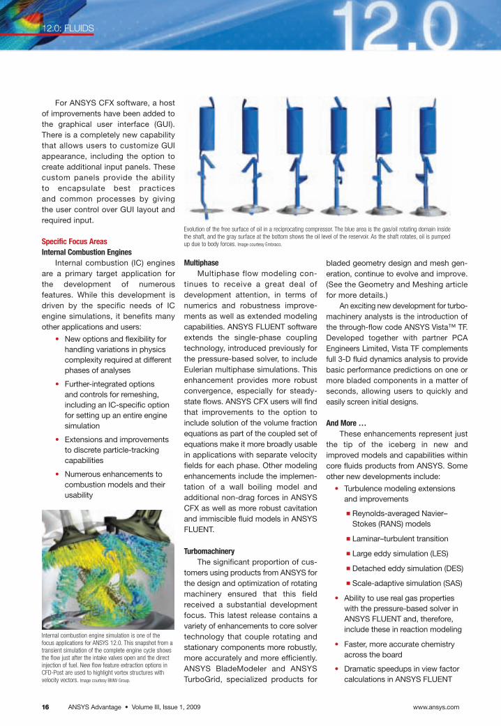
Evolution of the free surface of oil in a reciprocating compressor. The blue area is the gas/oil rotating domain insidethe shaft, and the gray surface at the bottom shows the oil level of the reservoir. As the shaft rotates, oil is pumpedup due to body forces. Image courtesy Embraco.
ANSYS Advantage • Volume III, Issue 1, 2009www.ansys.com 17
12.0: FLUIDS
1717
“ANSYS CFX 12.0 showed a 30 percent solver speedupin comparison with the previous release. This significant improvement allows
us to examine more design variations in the same time, enabling further design
optimization and considerably reducing the total development time. This helps
Embraco bring our products to the market more quickly.”
— Celso Kenzo TakemoriProduct and Process Technology ManagementEmbraco
CFD-Post can be used to compare multiple designs directly, both by examiningthem side by side and by looking at the calculated difference between results.Geometry courtesy CADFEM GmbH.
In work sponsored by BMT Seatech, partially-filled tanks on marine vessels are beingsimulated by researchers at the University of Southampton to predict structural loadsand changes in vessel behavior due to the sloshing of the fluid.
• Inclusion of convective terms insolids to model conjugate heattransfer in moving solids inANSYS CFX
• Ability to model thin surfaces inANSYS CFX
• Much more in areas such as particle tracking, fuel cells,acoustics, material propertiesand population balance methods
CFD-Post An exciting introduction is the
common post-processing applicationCFD-Post. The result of combiningtechnologies from both ANSYS FLUENT and ANSYS CFX tools and building upon the well-established
CFX-Post application, CFD-Post pro-vides a complete range of graphicalpost-processing options to allow usersto visualize and assess the flow predic-tions they have made and to createinsightful 2-D and 3-D images and animations. The application includespowerful tools for quantitative analysis,such as a complete range of options forcalculating weighted averages andautomatic report-generation capabil-ities. All steps can be scripted, allowingfor fully automated post-processing.Among the specific enhancements inrelease 12.0 are the ability to open andcompare multiple cases in the sameCFD-Post session and the addition oftools to locate vortex cores in the predicted flow field.
ConclusionThis is only a sampling of what the
fluid dynamics development teamshave produced for ANSYS 12.0. Thecombined depth and breadth of CFD knowledge and experience isdelivering benefits to all users as technologies are combined and devel-opment teams drive simulationtechnology to new levels of achieve-ment. With release 12.0, ANSYScontinues its commitment to provideleading-edge CFD technology. ■
This article was written through contributionsfrom Chris Wolfe and John Stokes of ANSYS, Inc.
www.ansys.comANSYS Advantage • Volume III, Issue 1, 20091818
12.0: STRUCTURAL MECHANICS
Designing with StructureAdvancements in structural mechanics allow more efficient and higher-fidelity modeling of complex structural phenomena.
The ability to drive the engineering design process instructural applications has taken a significant step forwardwith the improvements in release 12.0. New features andtools, many integrated into the ANSYS Workbench platform,help reduce overall solution time. Specific improvementsfocus on elements, materials and contact and solverperformance, along with linear, rigid and flexible dynamics.
ElementsThe most notable new element in release 12.0 is the
four-noded tetrahedron for modeling complex geometries inhyperelastic or forming applications. The element providesa convenient way to automate the meshing of complexstructures, avoiding the need for pure hexahedral meshes.This reduces the time it takes to develop a case from geom-etry through solution, while maintaining the accuracy of thesolution. See the table below for a summary of new andenhanced elements.
When simulating a nonlinear process, large deformationcan introduce too much distortion of the elements. Resolving
this requires local remeshing during the simulationprocess. The 2-D rezoning introduced with release 11.0extends further in ANSYS 12.0, increasing the flexibility ofthe remeshing process: The user can now define transitionregions within the refined zones and use meshes createdin external meshing tools.
MaterialsAccounting for proper cyclic softening or hardening or
damage of materials is a key factor for elastomer applica-tions and, more generally speaking, any structure whosematerial variation depends on the strain rate. Release 12.0introduces several additions to the wide choice of materi-als already available. Other feature improvements include:
• Rate-dependent Chaboche plasticity, which canbenefit turbine and engine design
• Bergström–Boyce model to enhance elastomermodeling capabilities
• New damage model based on the Ogden–Roxburgh formulation
Element New Improved Capability Applications
Four-noded tetrahedron X Provides a convenient way to automatemeshing of complex structures, avoidingneed for pure hexahedral meshes
Modeling complex geometries for forming or hyperelastic applications
General axisymmetric element X Supports contact Compatible with 3-D non-axisymmetric loading and canuse arbitrary axis of rotation
Various pipe model elements X Increased accuracy To provide refined behavior of structures in case of ovalization, warping or similar deformations of cross section for thin or moderately thick pipes and nonlinear material behavior support
Shell: linear, quadratic, axisymmetric X Improved shell thickness updating schemeand improved convergence
Provides greater accuracy in the behavior of shell modelsas well as a faster solution for nonlinear problems
Beam X Supports cubic shape function Provides additional accuracy to coarse meshes and greater support of complex load patterns
Reinforcement elements X Allows modeling of discrete fibers with a variety of nonlinear material behavior
Stresses in reinforcements can be analyzed separately from host elements
Summary of new and enhanced element features in ANSYS 12.0 structural analysis products
Warping and ovalization of pipe structureswith the new pipe elements
ANSYS Advantage • Volume III, Issue 1, 2009www.ansys.com 19191919
12.0: STRUCTURAL MECHANICS
• Anand’s viscoplasticity model, useful for metalforming applications such as solder joints
• Improvements in the calculation of J-integrals toaccount for mixed-mode stress intensity factors,which benefit improvements in fracture mechanics
• Initial strain and initial plastic stress import capabilities that allow for state transfer from a 2-D model to a 3-D model
ContactAs assemblies have become a de facto standard in
simulation, the need for advanced contact features hasgrown accordingly. ANSYS 12.0 developments include anumber of additional contact modeling features as well assignificant improvements in solving contact problems.
While Coulomb’s law for friction is widely used, there arecircumstances in which more elaborate modeling isrequired, such as wear modeling or pipelines resting on seabeds. Release 12.0 supports a friction coefficient definitionthat depends upon the contact state itself and accounts forcomplex frictional behavior. Specifically, the user is able todefine the dependency of the friction on contact parame-ters, such as sliding distance or contact pressure.
A typical contact application involves seals that are sub-ject to fluid pressure. Release 12.0 provides support of fluidpressure penetration, to model scenarios in which pressurerises higher than the contact pressure around the seal.Pressures in such cases can be applied only on the freefaces of the structure and evolve with the contact state.
Contact simulation is usually a time-consumingprocess. The latest release introduces contact modelingimprovements that significantly reduce computation timeand results file size. These enhancements include new
Performance of new modal solver
80,000
60,000
40,000
20,000
0
Number of Modes
contact search algorithms, contact trimming logic andsmart over-constraint elimination for multipoint constraint(MPC) contact.
Solver PerformanceSolver performance has improved in many different
areas. ANSYS 12.0 introduces a new modal solver, calledSNODE, that increases the speed of computation for prob-lems with a large number of modes — in the realm ofseveral hundred — on large structures that typically haveover a million degrees of freedom. This solver is well suitedfor automotive or aerospace applications and for largebeams and shell assemblies. Beyond its ability to computea larger number of modes in a reduced amount of time,SNODE also significantly reduces the amount of I/Orequired to compute the solution. (See the SupernodeEigensolver article.)
Many enhancements have been made to the distributedsolver to improve the scalability of the solution. (See the article on High Performance Computing.) More solvertechniques are supported, including:
• Partial solve capability that computes only a portionof the solution
• Prestressed analysis
• Models that employ the use of unsymmetric matrices, which are useful for scenarios that involvehigh-friction coefficients, for example
These new features can be combined for applicationssuch as brake squeal, which might combine the partialsolve and unsymmetric matrix capabilities.
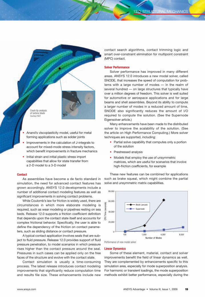
Crack tip analysis of turbine bladeCourtesy PADT
Linear DynamicsSome of these element, material, contact and solver
improvements benefit the field of linear dynamics as well.They are complemented by enhancements specific to thissimulation area, especially for mode superposition analysis.For harmonic or transient loadings, the mode superpositionmethods exhibit better performance, especially during the
CPU
Tim
e (s
econ
ds)
100 1,000 4,000 8,000
Block Lanczos
Supernode
so-called expansion pass that computes results at each frequency or time step on the full model. For very largestructures, the total computation effort can be reduced by up to 75 percent. The mode combination for spectralanalysis benefits from similar advancements. Instability predictions, such as the case of brake squeal, can becomputed faster due to several enhancements to thedamped eigensolver.
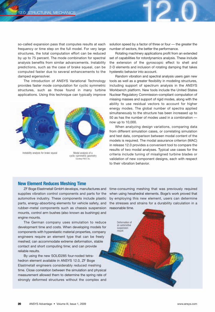
The introduction of ANSYS Variational Technology provides faster mode computation for cyclic symmetricstructures, such as those found in many turbine applications. Using this technique can typically improve
Instability analysis for brake squeal Modal analysis of a cyclic–symmetric geometry
Courtesy PADT, Inc.
solution speed by a factor of three or four — the greater thenumber of sectors, the better the performance.
Rotating machinery applications profit from an extendedset of capabilities for rotordynamics analysis. These includethe extension of the gyroscopic effect to shell and 2-D elements and inclusion of rotating damping that takeshysteretic behavior into account.
Random vibration and spectral analysis users gain newtools as well as a greater flexibility in modeling structures,including support of spectrum analysis in the ANSYS Workbench platform. New tools include the United StatesNuclear Regulatory Commission–compliant computation ofmissing masses and support of rigid modes, along with theability to use residual vectors to account for higher energy modes. The global number of spectra appliedsimultaneously to the structure has been increased up to50 as has the number of modes used in a combination —now up to 10,000.
When analyzing design variations, comparing datafrom different simulation cases, or correlating simulationand test data, comparison between modal content of themodels is required. The modal assurance criterion (MAC)in release 12.0 provides a convenient tool to compare theresults of two modal analyses. Typical use cases for thecriteria include tuning of misaligned turbine blades orvalidation of new component designs, each with respectto their vibration behavior.
New Element Reduces Meshing TimeZF Boge Elastmetall GmbH develops, manufactures and
supplies vibration control components and parts for theautomotive industry. These components include plasticparts, energy-absorbing elements for vehicle safety, and rubber–metal components such as chassis suspensionmounts, control arm bushes (also known as bushings) andengine mounts.
The German company uses simulation to reducedevelopment time and costs. When developing models forcomponents with hyperelastic material properties, companyengineers require an element type that can be freelymeshed; can accommodate extreme deformation, stablecontact and short computing time; and can provide reliable results.
By using the new SOLID285 four-noded tetra-hedron element available in ANSYS 12.0, ZF BogeElastmetall engineers considerably reduced meshingtime. Close correlation between the simulation and physicalmeasurement allowed them to determine the spring rate ofstrongly deformed structures without the complex and
Deformation ofan automotivesuspensionmount
www.ansys.comANSYS Advantage • Volume III, Issue 1, 200920202020
12.0: STRUCTURAL MECHANICS
time-consuming meshing that was previously requiredwhen using hexahedral elements. Boge’s work proved thatby employing this new element, users can determinethe stresses and strains for a durability calculation in a reasonable time.
ANSYS Advantage • Volume III, Issue 1, 2009www.ansys.com 21212121
ANSYS Workbench IntegrationThe integration of the structural applications within
the ANSYS Workbench platform provides additionalproductivity to users, including:
• New meshing techniques to improve mesh quality
• Support of additional elements, such as gasket elements as well as quadratic shells and beams that include offset definitions
• Boundary condition definitions that provide a spatial dependency for loads
• Coupling conditions
• Remote points
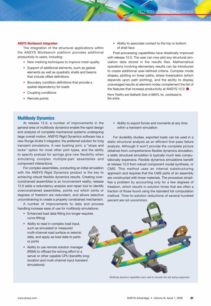
Multibody DynamicsAt release 12.0, a number of improvements in the
general area of multibody dynamics enable the rapid designand analysis of complete mechanical systems undergoinglarge overall motion. ANSYS Rigid Dynamics software has anew Runge–Kutta 5 integrator, the preferred solution for longtransient simulations. A new bushing joint, a “stops andlocks” option for most other joint types, and the ability to specify preload for springs give new flexibility when simulating complex multiple-part assemblies andcomponent interactions.
For complex assemblies, conducting an initial simulationwith the ANSYS Rigid Dynamics product is the key toachieving robust flexible dynamics results. Creating over-constrained assemblies is an inconvenient reality; release12.0 adds a redundancy analysis and repair tool to identifyoverconstrained assemblies, points out which joints ordegrees of freedom are redundant, and allows selectiveunconstraining to create a properly constrained mechanism.
A number of improvements to data and process handling increase ease of use for multibody simulations:
• Enhanced load data fitting (no longer requires curve fitting)
• Ability to read in complex load input,such as simulated or measured multi-channel road surface or seismicdata, and apply as load data to partsor joints
• Ability to use remote solution manager(RSM) to offload the solving effort to aserver or other capable CPU (benefits long-duration and multi-channel input transientsimulations)
12.0: STRUCTURAL MECHANICS
Multibody dynamics capabilities were used to simulate this leaf spring suspension.
• Ability to export forces and moments at any timewithin a transient simulation
For durability studies, exported loads can be used in astatic structural analysis as an efficient first-pass failureanalysis. Although it won’t provide the complete pictureobtained from comprehensive flexible dynamics simulation,a static structural simulation is typically much less compu-tationally expensive. Flexible dynamics simulations benefitat release 12.0 from robust component modal synthesis, orCMS. This method uses an internal substructuringapproach and requires that the CMS parts of an assemblyare constructed with linear materials. The procedure simpli-fies a problem by accounting only for a few degrees offreedom, which results in solution times that are often afraction of those found using the standard full computationmethod. Time-to-solution reductions of several hundredpercent are not uncommon.
• Ability to associate contact to the top or bottom of shell face
Post-processing capabilities have drastically improvedwith release 12.0. The user can now plot any structural sim-ulation data stored in the results files. Mathematicaloperations involving elementary results can be introducedto create additional user-defined criteria. Complex modeshapes, plotting on linear paths, stress linearization (whichdepends upon path plotting), and the ability to displayunaveraged results at element nodes complement the list ofthe features that increase productivity at ANSYS 12.0. ■
Pierre Thieffry and Siddharth Shah of ANSYS, Inc. contributed to this article.
www.ansys.comANSYS Advantage • Volume III, Issue 1, 200922222222 www.ansys.com22
12.0: EXPLICIT DYNAMICS
Explicit Dynamics Goes MainstreamANSYS 12.0 brings native explicit dynamics to ANSYS Workbench and provides the easiest explicit software for nonlinear dynamics.
ANSYS has expended significanteffort in the area of explicit dynamics forrelease 12.0 — including the addition ofa new product that will make this tech-nology accessible to users independentof their simulation experience. In addi-tion, enhancements to both the ANSYSAUTODYN and ANSYS LS-DYNAproducts provide considerable benefitsto their users.
Newly introduced in ANSYS 12.0,ANSYS Explicit STR software is the firstexplicit dynamics product with a nativeANSYS Workbench interface. It is basedon the Lagrangian portion of the ANSYSAUTODYN product. The technology willappeal to those who want to model transient dynamic events such as droptests, as well as quasi-static eventsinvolving rapidly changing contact conditions, sophisticated material failure/damage and/or severe displace-ments and rotations of structures. Inaddition, it will appeal to users who canbenefit from the productivity provided byother applications integrated within theANSYS Workbench environment.Those who have previous experienceusing ANSYS Workbench will find that
they already know most of what is needed to use ANSYS Explicit STR.
The ANSYS Explicit STR tool is wellsuited to solving:
• Drop tests (electronics and consumer goods)
• Low- to high-speed solid-to-solidimpacts (a wide range of applica-tions from sporting goods toaerospace)
• Highly nonlinear plastic buckling events (for ultimate limit state design)
• Complete material failure applications (defense and homeland security)
• Breakable contact, such as adhesives or spot welds (electronics and automotive)
The real benefit of ANSYS ExplicitSTR software is the work flow afforded by operating in the ANSYS Workbench environment. While many differentsimulation processes are possible, here is an example of the typical steps a usermight take:
• Associatively link to a parametricCAD model or import a geometry
• Create a smooth explicit mesh using the new explicit preferenceoption and/or patch-independentmesh method within the ANSYSmeshing platform; automatically create part-to-part contact by usingthe new body interactions tool
• Fine-tune contact specifications ifdesired by utilizing breakable or eroding contact options
• Load and/or support an assemblyand/or parts as usual
• Assign material properties from thecomprehensive material library
• Solve interactively either in thebackground or via remote solutionmanager (RSM)
• View progress of solution in real time using concurrent post-processing capability, new toANSYS Workbench at 12.0
• Explore alternative design ideas via parametric changes to the CAD model and easily perform re-solves,just like other ANSYS Workbenchbased applications
• Use the ANSYS Design Explorationcapability to automate the para-metric model space exploration
In addition, users of the full version ofANSYS AUTODYN (structural- plus fluids-capable) have access to the ANSYSExplicit STR interface; consequently, theywill be able to transfer implicit solutionsfrom the ANSYS Workbench environmentfor doing implicit–explicit solutions, suchas bird strike analysis of a pre-stressed fanblade. ANSYS LS-DYNA software userswill be able to use the pre-processing portion of ANSYS Explicit STR and outputa .K file for solving and post-processingoutside of ANSYS Workbench. ■
Wim J. Slagter of ANSYS, Inc. is available toanswer your questions about explicit dynamics.ANSYS Explicit STR is the first explicit dynamics product with a native ANSYS Workbench interface.
ANSYS Advantage • Volume III, Issue 1, 2009www.ansys.com 232323
12.0: EIGENSOLVER
Introducing the Supernode EigensolverA new eigensolver in ANSYS 12.0 determines large numbers of natural frequency modes more quickly and efficiently than conventional methods.By Jeff Beisheim, Senior Development Engineer, ANSYS, Inc.
In a wide range of applications, parts are subject tocyclic mechanical loading, and engineers must use aneigensolver to determine the structure’s natural frequencies— also known as eigen modes. With some modes, largevibration amplitudes can interfere with product performanceand cause damage, such as fatigue cracking. In mostcases, only the first few modes with the largest deforma-tions are of particular interest, though determining evendozens of modes can be common.
In the CAE industry, the block Lanczos eigensolver istypically used more than any other for these types of calcu-lations. This proven algorithm has been used in many finiteelement software packages, including ANSYS Mechanicaltechnology. It brings together the efficiency and accuracy ofthe Lanczos algorithm and the robustness of a sparse directequation solver. The software works in a sequential fashionby computing one mode (or a block of modes) at a time untilall desired modes have been computed.
Although the method is considered efficient in solvingfor each of these eigen modes, the amount of time andcomputer resources (both memory and I/O) required addsup when many dozens of eigen modes must be found.Elapsed solution times of several hours — or days — aretypical in applications that involve thousands of modes.Generally, determining large numbers of modes is requiredin capturing system response for studies such as transientor harmonic analyses using the mode superpositionmethod.
For such cases, the ANSYS release 12.0 includes a newsupernode eigensolver. Instead of computing each modeindividually and working with mode shapes in the globalmodel space, the supernode algorithm uses a mathematicalapproach based on substructuring to simultaneously deter-mine all modes within a given frequency range and tomanage data in a reduced model space.
By utilizing fewer resources than block Lanczos, thissupernode eigensolver becomes an ideal choice when solving on a desktop computer, which can have limitedmemory and relatively slow I/O performance. When com-bined with current eigensolver technology already availablein mechanical software from ANSYS, virtually all modalanalyses can be efficiently solved.
The ANSYS supernode eigensolver is well suited for applications such as seismic analysis of power plant cooling towers, skyscrapers and other structures in which hundreds of modes must be extracted to determine the response of the structures to multiple short-duration transient shock/impact loadings.
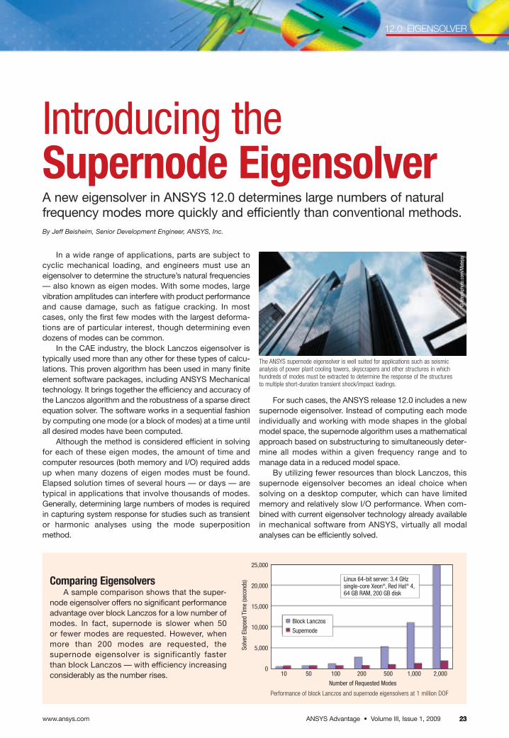
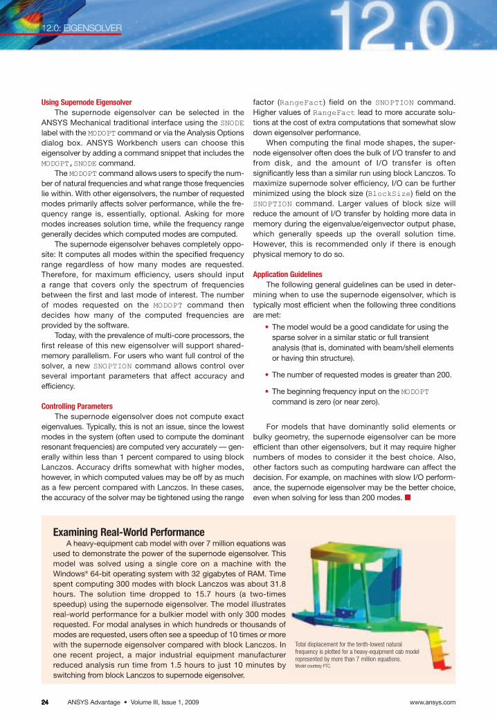
Comparing EigensolversA sample comparison shows that the super-
node eigensolver offers no significant performanceadvantage over block Lanczos for a low number ofmodes. In fact, supernode is slower when 50 or fewer modes are requested. However, whenmore than 200 modes are requested, the supernode eigensolver is significantly fasterthan block Lanczos — with efficiency increasingconsiderably as the number rises.
Performance of block Lanczos and supernode eigensolvers at 1 million DOF
25,000
20,000
15,000
10,000
5,000
0
Solv
er E
laps
ed T
ime
(sec
onds
)
10 50 100 200 500 1,000 2,000
Number of Requested Modes
Block Lanczos
Supernode
Linux 64-bit server: 3.4 GHzsingle-core Xeon®, Red Hat® 4,64 GB RAM, 200 GB disk
© is
tock
phot
o.co
m/M
atej
ay
www.ansys.comANSYS Advantage • Volume III, Issue 1, 20092424242424
12.0: EIGENSOLVER
Using Supernode EigensolverThe supernode eigensolver can be selected in the
ANSYS Mechanical traditional interface using the SNODElabel with the MODOPT command or via the Analysis Optionsdialog box. ANSYS Workbench users can choose thiseigensolver by adding a command snippet that includes theMODOPT,SNODE command.
The MODOPT command allows users to specify the num-ber of natural frequencies and what range those frequencieslie within. With other eigensolvers, the number of requestedmodes primarily affects solver performance, while the fre-quency range is, essentially, optional. Asking for moremodes increases solution time, while the frequency rangegenerally decides which computed modes are computed.
The supernode eigensolver behaves completely oppo-site: It computes all modes within the specified frequencyrange regardless of how many modes are requested.Therefore, for maximum efficiency, users should input a range that covers only the spectrum of frequenciesbetween the first and last mode of interest. The number of modes requested on the MODOPT command thendecides how many of the computed frequencies are provided by the software.
Today, with the prevalence of multi-core processors, thefirst release of this new eigensolver will support shared-memory parallelism. For users who want full control of thesolver, a new SNOPTION command allows control over several important parameters that affect accuracy and efficiency.
Controlling ParametersThe supernode eigensolver does not compute exact
eigenvalues. Typically, this is not an issue, since the lowestmodes in the system (often used to compute the dominantresonant frequencies) are computed very accurately — gen-erally within less than 1 percent compared to using blockLanczos. Accuracy drifts somewhat with higher modes,however, in which computed values may be off by as muchas a few percent compared with Lanczos. In these cases,the accuracy of the solver may be tightened using the range
Examining Real-World PerformanceA heavy-equipment cab model with over 7 million equations was
used to demonstrate the power of the supernode eigensolver. Thismodel was solved using a single core on a machine with the Windows® 64-bit operating system with 32 gigabytes of RAM. Timespent computing 300 modes with block Lanczos was about 31.8hours. The solution time dropped to 15.7 hours (a two-timesspeedup) using the supernode eigensolver. The model illustratesreal-world performance for a bulkier model with only 300 modesrequested. For modal analyses in which hundreds or thousands ofmodes are requested, users often see a speedup of 10 times or morewith the supernode eigensolver compared with block Lanczos. Inone recent project, a major industrial equipment manufacturerreduced analysis run time from 1.5 hours to just 10 minutes byswitching from block Lanczos to supernode eigensolver.
Total displacement for the tenth-lowest natural frequency is plotted for a heavy-equipment cab modelrepresented by more than 7 million equations.Model courtesy PTC.
factor (RangeFact) field on the SNOPTION command.Higher values of RangeFact lead to more accurate solu-tions at the cost of extra computations that somewhat slowdown eigensolver performance.
When computing the final mode shapes, the super-node eigensolver often does the bulk of I/O transfer to andfrom disk, and the amount of I/O transfer is oftensignificantly less than a similar run using block Lanczos. Tomaximize supernode solver efficiency, I/O can be furtherminimized using the block size (BlockSize) field on theSNOPTION command. Larger values of block size willreduce the amount of I/O transfer by holding more data inmemory during the eigenvalue/eigenvector output phase,which generally speeds up the overall solution time. However, this is recommended only if there is enoughphysical memory to do so.
Application GuidelinesThe following general guidelines can be used in deter-
mining when to use the supernode eigensolver, which istypically most efficient when the following three conditionsare met:
• The model would be a good candidate for using thesparse solver in a similar static or full transient analysis (that is, dominated with beam/shell elementsor having thin structure).
• The number of requested modes is greater than 200.
• The beginning frequency input on the MODOPTcommand is zero (or near zero).
For models that have dominantly solid elements orbulky geometry, the supernode eigensolver can be moreefficient than other eigensolvers, but it may require highernumbers of modes to consider it the best choice. Also,other factors such as computing hardware can affect thedecision. For example, on machines with slow I/O perform-ance, the supernode eigensolver may be the better choice,even when solving for less than 200 modes. ■
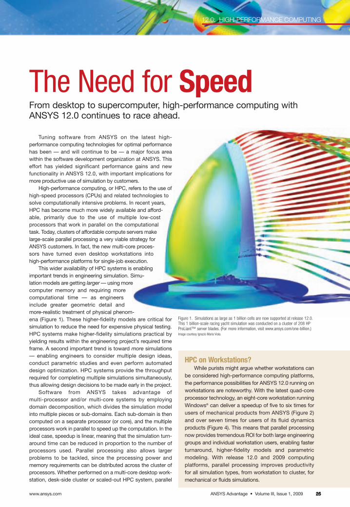
ANSYS Advantage • Volume III, Issue 1, 2009www.ansys.com 25252525
12.0: HIGH-PERFORMANCE COMPUTING
25
The Need for SpeedFrom desktop to supercomputer, high-performance computing withANSYS 12.0 continues to race ahead.
Tuning software from ANSYS on the latest high-performance computing technologies for optimal performancehas been — and will continue to be — a major focus area within the software development organization at ANSYS. Thiseffort has yielded significant performance gains and new functionality in ANSYS 12.0, with important implications formore productive use of simulation by customers.
High-performance computing, or HPC, refers to the use ofhigh-speed processors (CPUs) and related technologies tosolve computationally intensive problems. In recent years,HPC has become much more widely available and afford-able, primarily due to the use of multiple low-costprocessors that work in parallel on the computationaltask. Today, clusters of affordable compute servers makelarge-scale parallel processing a very viable strategy forANSYS customers. In fact, the new multi-core proces-sors have turned even desktop workstations intohigh-performance platforms for single-job execution.
This wider availability of HPC systems is enablingimportant trends in engineering simulation. Simu-lation models are getting larger — using morecomputer memory and requiring morecomputational time — as engineersinclude greater geometric detail andmore-realistic treatment of physical phenom-ena (Figure 1). These higher-fidelity models are critical forsimulation to reduce the need for expensive physical testing.HPC systems make higher-fidelity simulations practical byyielding results within the engineering project’s required timeframe. A second important trend is toward more simulations— enabling engineers to consider multiple design ideas, conduct parametric studies and even perform automateddesign optimization. HPC systems provide the throughputrequired for completing multiple simulations simultaneously,thus allowing design decisions to be made early in the project.
Software from ANSYS takes advantage of multi-processor and/or multi-core systems by employingdomain decomposition, which divides the simulation modelinto multiple pieces or sub-domains. Each sub-domain is thencomputed on a separate processor (or core), and the multipleprocessors work in parallel to speed up the computation. In theideal case, speedup is linear, meaning that the simulation turn-around time can be reduced in proportion to the number ofprocessors used. Parallel processing also allows larger problems to be tackled, since the processing power and memory requirements can be distributed across the cluster ofprocessors. Whether performed on a multi-core desktop work-station, desk-side cluster or scaled-out HPC system, parallel
HPC on Workstations?While purists might argue whether workstations can
be considered high-performance computing platforms,the performance possibilities for ANSYS 12.0 running onworkstations are noteworthy. With the latest quad-coreprocessor technology, an eight-core workstation runningWindows® can deliver a speedup of five to six times forusers of mechanical products from ANSYS (Figure 2)and over seven times for users of its fluid dynamicsproducts (Figure 4). This means that parallel processingnow provides tremendous ROI for both large engineeringgroups and individual workstation users, enabling fasterturnaround, higher-fidelity models and parametric modeling. With release 12.0 and 2009 computing platforms, parallel processing improves productivity for all simulation types, from workstation to cluster, formechanical or fluids simulations.
Figure 1. Simulations as large as 1 billion cells are now supported at release 12.0.This 1 billion-scale racing yacht simulation was conducted on a cluster of 208 HPProLiant™ server blades. (For more information, visit www.ansys.com/one-billion.) Image courtesy Ignazio Maria Viola.
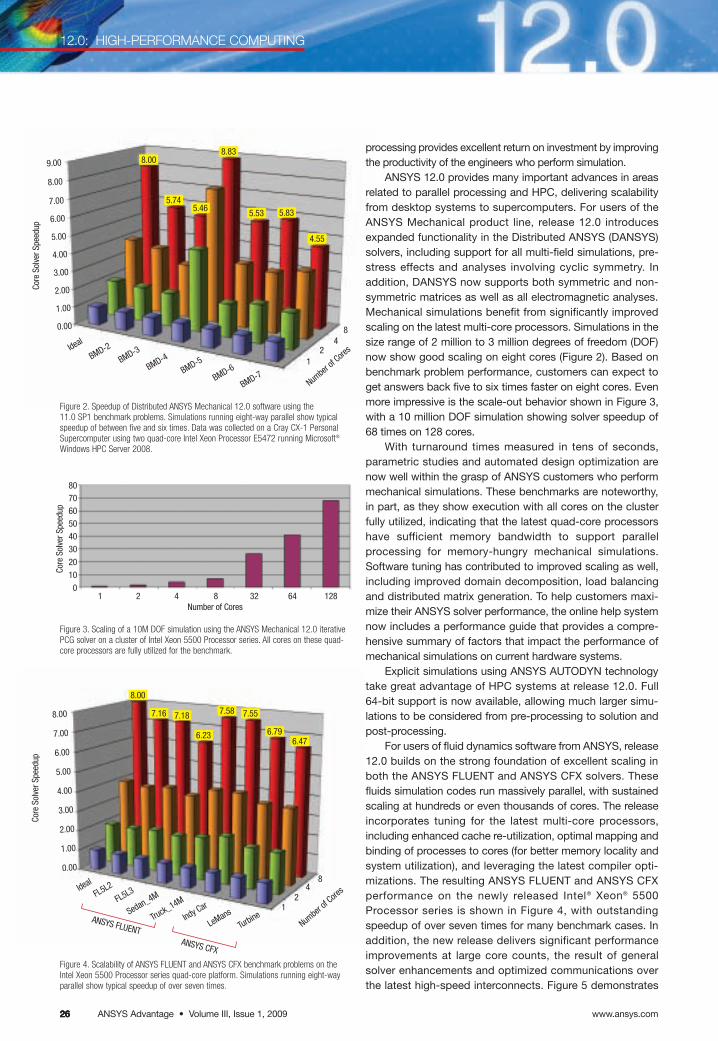
www.ansys.comANSYS Advantage • Volume III, Issue 1, 2009262626
12.0: HIGH-PERFORMANCE COMPUTING
Figure 3. Scaling of a 10M DOF simulation using the ANSYS Mechanical 12.0 iterativePCG solver on a cluster of Intel Xeon 5500 Processor series. All cores on these quad-core processors are fully utilized for the benchmark.
processing provides excellent return on investment by improvingthe productivity of the engineers who perform simulation.
ANSYS 12.0 provides many important advances in areasrelated to parallel processing and HPC, delivering scalabilityfrom desktop systems to supercomputers. For users of theANSYS Mechanical product line, release 12.0 introducesexpanded functionality in the Distributed ANSYS (DANSYS)solvers, including support for all multi-field simulations, pre-stress effects and analyses involving cyclic symmetry. Inaddition, DANSYS now supports both symmetric and non-symmetric matrices as well as all electromagnetic analyses.Mechanical simulations benefit from significantly improvedscaling on the latest multi-core processors. Simulations in thesize range of 2 million to 3 million degrees of freedom (DOF)now show good scaling on eight cores (Figure 2). Based onbenchmark problem performance, customers can expect toget answers back five to six times faster on eight cores. Evenmore impressive is the scale-out behavior shown in Figure 3,with a 10 million DOF simulation showing solver speedup of68 times on 128 cores.
With turnaround times measured in tens of seconds,parametric studies and automated design optimization arenow well within the grasp of ANSYS customers who performmechanical simulations. These benchmarks are noteworthy,in part, as they show execution with all cores on the clusterfully utilized, indicating that the latest quad-core processorshave sufficient memory bandwidth to support parallel processing for memory-hungry mechanical simulations. Software tuning has contributed to improved scaling as well,including improved domain decomposition, load balancingand distributed matrix generation. To help customers maxi-mize their ANSYS solver performance, the online help systemnow includes a performance guide that provides a compre-hensive summary of factors that impact the performance ofmechanical simulations on current hardware systems.
Explicit simulations using ANSYS AUTODYN technologytake great advantage of HPC systems at release 12.0. Full 64-bit support is now available, allowing much larger simu-lations to be considered from pre-processing to solution and post-processing.
For users of fluid dynamics software from ANSYS, release12.0 builds on the strong foundation of excellent scaling inboth the ANSYS FLUENT and ANSYS CFX solvers. These fluids simulation codes run massively parallel, with sustainedscaling at hundreds or even thousands of cores. The releaseincorporates tuning for the latest multi-core processors,including enhanced cache re-utilization, optimal mapping andbinding of processes to cores (for better memory locality andsystem utilization), and leveraging the latest compiler opti-mizations. The resulting ANSYS FLUENT and ANSYS CFXperformance on the newly released Intel® Xeon® 5500 Processor series is shown in Figure 4, with outstandingspeedup of over seven times for many benchmark cases. Inaddition, the new release delivers significant performanceimprovements at large core counts, the result of generalsolver enhancements and optimized communications overthe latest high-speed interconnects. Figure 5 demonstrates
80706050403020100
1 2 4 8 32 64 128
Core
Sol
ver S
peed
up
Number of Cores
9.00
8.00
7.00
6.00
5.00
4.00
3.00
2.00
1.00
0.00
Ideal
BMD-2
BMD-3
BMD-4
BMD-5
BMD-6
BMD-7
12
48
8.00
5.745.46
8.83
5.53 5.83
4.55
Numbe
r of C
ores
Core
Sol
ver S
peed
up
8.00
7.00
6.00
5.00
4.00
3.00
2.00
1.00
0.00
Ideal
FL5L2
FL5L3
Sedan_4M
Truck_14M
Indy Car
LeMans
Turbine1
24
8
8.00
7.16 7.18
6.23
7.58 7.55
6.796.47
Numbe
r of C
ores
Core
Sol
ver S
peed
up
ANSYS FLUENTANSYS CFX
Figure 4. Scalability of ANSYS FLUENT and ANSYS CFX benchmark problems on theIntel Xeon 5500 Processor series quad-core platform. Simulations running eight-wayparallel show typical speedup of over seven times.
Figure 2. Speedup of Distributed ANSYS Mechanical 12.0 software using the 11.0 SP1 benchmark problems. Simulations running eight-way parallel show typicalspeedup of between five and six times. Data was collected on a Cray CX-1 PersonalSupercomputer using two quad-core Intel Xeon Processor E5472 running Microsoft®
Windows HPC Server 2008.
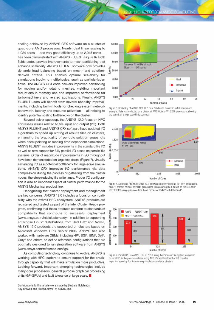
ANSYS Advantage • Volume III, Issue 1, 2009www.ansys.com 27
12.0: HIGH-PERFORMANCE COMPUTING
27
Figure 5. Scalability of ANSYS CFX 12.0 on a 10M node transonic airfoil benchmarkexample. Data was collected on a cluster of AMD Opteron™ 2218 processors, showingthe benefit of a high-speed interconnect.
Figure 7. Parallel I/O in ANSYS FLUENT 12.0 using the Panasas© file system, comparedto serial I/O in the previous release using NFS. Parallel treatment of I/O provides important speedup for time-varying simulations on large clusters.
273
345334
PanFS – FLUENT 12
NFS – FLUENT6.3
Figure 6. Scaling of ANSYS FLUENT 12.0 software is nearly ideal up to 1,024 processorsand 78 percent of ideal at 2,048 processors. Data courtesy SGI, based on the SGI Altix®
ICE 8200EX using quad-core Intel Xeon Processor E5472 with Infiniband®.
scaling achieved by ANSYS CFX software on a cluster ofquad-core AMD processors. Nearly ideal linear scaling to1,024 cores — and very good efficiency up to 2,048 cores —has been demonstrated with ANSYS FLUENT (Figure 6). Bothfluids codes provide improvements to mesh partitioning thatenhance scalability. ANSYS FLUENT software now providesdynamic load balancing based on mesh- and solution-derived criteria. This enables optimal scalability forsimulations involving multiphysics, such as particle-ladenflows. The ANSYS CFX code delivers improved partitioningfor moving and/or rotating meshes, yielding important reductions in memory use and improved performance for turbomachinery and related applications. Finally, ANSYSFLUENT users will benefit from several usability improve-ments, including built-in tools for checking system networkbandwidth, latency and resource utilization — all helping toidentify potential scaling bottlenecks on the cluster.
Beyond solver speedup, the ANSYS 12.0 focus on HPCaddresses issues related to file input and output (I/O). BothANSYS FLUENT and ANSYS CFX software have updated I/Oalgorithms to speed up writing of results files on clusters,enhancing the practicality of periodic solution snapshotswhen checkpointing or running time-dependent simulations.ANSYS FLUENT includes improvements in the standard file I/Oas well as new support for fully parallel I/O based on parallel filesystems. Order of magnitude improvements in I/O throughputhave been demonstrated on large test cases (Figure 7), virtuallyeliminating I/O as a potential bottleneck for large-scale simula-tions. ANSYS CFX improves I/O performance via datacompression during the process of gathering from the clusternodes, therefore reducing file write times. Proper I/O configura-tion is also an important aspect of cluster performance for theANSYS Mechanical product line.
Recognizing that cluster deployment and managementare key concerns, ANSYS 12.0 includes a focus on compati-bility with the overall HPC ecosystem. ANSYS products areregistered and tested as part of the Intel Cluster Ready pro-gram, confirming that these products conform to standards ofcompatibility that contribute to successful deployment(www.ansys.com/intelclusterready). In addition to supportingenterprise Linux® distributions from Red Hat® and Novell,ANSYS 12.0 products are supported on clusters based onMicrosoft Windows HPC Server 2008. ANSYS has alsoworked with hardware OEMs, including HP®, SGI®, IBM®, Dell®,Cray® and others, to define reference configurations that areoptimally designed to run simulation software from ANSYS(www.ansys.com/reference-configs).
As computing technology continues to evolve, ANSYS isworking with HPC leaders to ensure support for the break-through capability that will make simulation more productive.Looking forward, important emerging technologies includemany-core processors, general purpose graphical processingunits (GP-GPUs) and fault tolerance at large scale. ■
Contributions to this article were made by Barbara Hutchings,Ray Browell and Prasad Alavilli of ANSYS, Inc.
Spee
dup
Number of Cores
Ideal
Infiniband
Gigabit
120.00
100.00
80.00
60.00
40.00
20.00
0.00
2,048
1,536
1,024
512
00 512 1,024 1,536 2,048
Number of Cores
I/O R
ate
for D
ata
Writ
e (M
Byte
s/se
c) 400
300
200
100
0
273
39X
345334
64 128 256
Solv
er S
peed
up
Number of Cores
1,581
991
521
265128
0 16 32 48 64 80 96
PanFS — FLUENT 12.0
NFS — FLUENT6.3
Speedup
Ideal
Transonic Airfoil BenchmarkModel — 10M Nodes
Truck Benchmark Model — 111M Cells
31X 20X
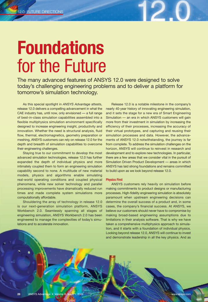
12.0: FUTURE DIRECTIONS
Foundationsfor the FutureThe many advanced features of ANSYS 12.0 were designed to solvetoday’s challenging engineering problems and to deliver a platform fortomorrow’s simulation technology.
As this special spotlight in ANSYS Advantage attests,release 12.0 delivers a compelling advancement in what theCAE industry has, until now, only envisioned — a full rangeof best-in-class simulation capabilities assembled into aflexible multiphysics simulation environment specificallydesigned to increase engineering insight, productivity andinnovation. Whether the need is structural analysis, fluidflow, thermal, electromagnetics, geometry preparation ormeshing, ANSYS customers can rely on release 12.0 for thedepth and breadth of simulation capabilities to overcometheir engineering challenges.
Staying true to our commitment to develop the mostadvanced simulation technologies, release 12.0 has furtherexpanded the depth of individual physics and more intimately coupled them to form an engineering simulationcapability second to none. A multitude of new materialmodels, physics and algorithms enable simulating real-world operating conditions and coupled physical phenomena, while new solver technology and parallel processing improvements have dramatically reduced runtimes and made complete system simulations more computationally affordable.
Shouldering the array of technology in release 12.0 is our next-generation simulation platform, ANSYSWorkbench 2.0. Seamlessly spanning all stages of engineering simulation, ANSYS Workbench 2.0 has beenengineered to manage the complexities of today’s simu-lations and to accelerate innovation.
Release 12.0 is a notable milestone in the company’snearly 40-year history of innovating engineering simulation,and it sets the stage for a new era of Smart EngineeringSimulation — an era in which ANSYS customers will gainmore from their investment in simulation by increasing theefficiency of their processes, increasing the accuracy oftheir virtual prototypes, and capturing and reusing their simulation processes and data. However, the advance-ments of ANSYS 12.0 notwithstanding, the journey is farfrom complete. To address the simulation challenges on thehorizon, ANSYS will continue to reinvest in research anddevelopment and to explore new technologies. In particular,there are a few areas that we consider vital in the pursuit ofSimulation Driven Product Development — areas in whichANSYS has laid strong foundations and remains committedto build upon as we look beyond release 12.0.
Physics FirstANSYS customers rely heavily on simulation before
making commitments to product designs or manufacturingprocesses. High-fidelity engineering simulation is absolutelyparamount when upstream engineering decisions candetermine the overall success of a product and, in somecases, the company’s financial success. At ANSYS, webelieve our customers should never have to compromise bymaking broad-based engineering assumptions due to limitations in their analysis software. That is why we havetaken a comprehensive multiphysics approach to simula-tion, and it starts with a foundation of individual physics.Looking beyond release 12.0, ANSYS will continue to investand demonstrate leadership in all the key physics. And as
www.ansys.comANSYS Advantage • Volume III, Issue 1, 20092828
12.0: FUTURE DIRECTIONS
we develop tomorrow’s advanced capabilities, we will con-tinue to allow them to be combined in ways that freeengineers from making the assumptions associated withsingle-physics simulations. Within the ANSYS Workbenchsimulation paradigm, we will enable engineers to routinelyconsider the effects of fully coupled physical phenomena.
High-Performance ComputingAs one might expect, high-performance computing
(HPC) is a strategic enabling technology for ANSYS. Theappearance of quad-core machines on the desktop and theincreased availability of compute clusters have ushered in a new era of parallel and distributed computing for our customers. ANSYS has kept pace with the exponentialincrease in computational horsepower with prolific develop-ment in the areas of parallel and distributed computing andnumerical methods. The result is improved scalability anddramatically reduced run times for large-scale fluid flow,structural and electromagnetic simulations.
Solving large-scale problems with meshes exceeding 1 billion cells has been the latest stretch goal for fluid flow simulation. Recently, HPC and software from ANSYSwere combined to investigate the aerodynamics of a racing yacht using 1 billion computational cells. Breakingthis barrier demonstrates our conviction for high-performance scientific computing. As computationalresources increase and engineering simulations becomelarger and more complex, we will continue to ensure thatour solvers scale appropriately. Moreover, our forwarddeployment of HPC technology is not limited to solvers. The complexity of today’s models and massive amounts of results data require more-scalable solutions forpreparing models and interpreting results as well.
ANSYS Workbench Framework The ANSYS Workbench 2.0 platform is a powerful multi-
domain simulation environment that harnesses the corephysics from ANSYS; enables their interoperability; andprovides common tools for interfacing with CAD, repairinggeometry, creating meshes and post-processing results.Instrumental to the successful integration of this unparal-leled breadth of technology is a “well-architected,” openand extendable software framework.
The ANSYS Workbench framework is designed to provide common services for engineering simulation
applications — data management, parameterization, scriptingand graphics, among others. Release 12.0 relies heavily onthe framework’s data management and parameterizationservices to integrate existing applications into the ANSYSWorkbench environment, where they have become highlyinteroperable. Over subsequent releases, these applicationswill leverage the framework’s graphical toolkit to establish aconsistent user interface and further blend the variousapplications integrated into the platform. At the onset ofdeveloping ANSYS Workbench 2.0, we identified scriptingand journaling as fundamental requirements of the newarchitecture. As such, a top-level scripting engine has beenthoughtfully designed and lays the groundwork for futureANSYS Workbench customization and batch processing.Looking beyond release 12.0, all these services will be further refined and will fuel rapid add-in development and a further expansion of capabilities. Over time, ANSYS customers and partners will leverage the framework’s open architecture, enlisting its services to create tailoredapplications, and will elevate ANSYS Workbench as an application development platform for the engineering simulation community.
Simulation Process and Data Management ANSYS Workbench 2.0 is an environment in which a
single analyst creates and executes one or more steps of anengineering simulation workflow. ANSYS EngineeringKnowledge Manager (EKM) extends ANSYS Workbench byproviding the tools to manage the work of a group of analysts and myriad simulation workflows. This includes system-level services to manage and foster collaborationon thousands of models, terabytes of results, hundreds ofdefined processes and huge investments in simulation.
Looking forward, ANSYS believes that managing dataand processes will become integral with engineering simu-lation. Ten years ago, simulation comprised three discreteand sequential phases: pre-processing, solving and post-processing. With the evolution of ANSYS Workbench, wenow look at engineering simulation as a continuous workflow intertwining these steps. In the same way,process and data management will become intertwined
ANSYS Advantage • Volume III, Issue 1, 2009www.ansys.com 2929
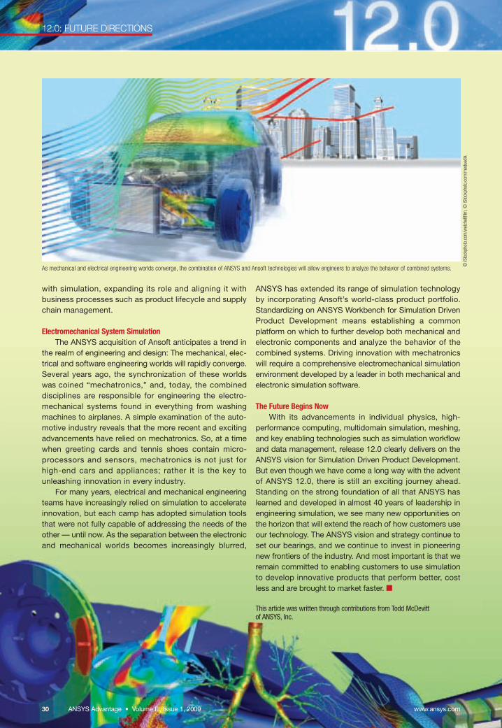
12.0: FUTURE DIRECTIONS
with simulation, expanding its role and aligning it withbusiness processes such as product lifecycle and supplychain management.
Electromechanical System SimulationThe ANSYS acquisition of Ansoft anticipates a trend in
the realm of engineering and design: The mechanical, elec-trical and software engineering worlds will rapidly converge.Several years ago, the synchronization of these worlds was coined “mechatronics,” and, today, the combineddisciplines are responsible for engineering the electro-mechanical systems found in everything from washingmachines to airplanes. A simple examination of the auto-motive industry reveals that the more recent and excitingadvancements have relied on mechatronics. So, at a timewhen greeting cards and tennis shoes contain micro-processors and sensors, mechatronics is not just forhigh-end cars and appliances; rather it is the key tounleashing innovation in every industry.
For many years, electrical and mechanical engineeringteams have increasingly relied on simulation to accelerateinnovation, but each camp has adopted simulation toolsthat were not fully capable of addressing the needs of theother — until now. As the separation between the electronicand mechanical worlds becomes increasingly blurred,
ANSYS has extended its range of simulation technology by incorporating Ansoft’s world-class product portfolio.Standardizing on ANSYS Workbench for Simulation DrivenProduct Development means establishing a common platform on which to further develop both mechanical andelectronic components and analyze the behavior of thecombined systems. Driving innovation with mechatronicswill require a comprehensive electromechanical simulationenvironment developed by a leader in both mechanical andelectronic simulation software.
The Future Begins NowWith its advancements in individual physics, high-
performance computing, multidomain simulation, meshing,and key enabling technologies such as simulation workflowand data management, release 12.0 clearly delivers on theANSYS vision for Simulation Driven Product Development.But even though we have come a long way with the adventof ANSYS 12.0, there is still an exciting journey ahead.Standing on the strong foundation of all that ANSYS haslearned and developed in almost 40 years of leadership inengineering simulation, we see many new opportunities onthe horizon that will extend the reach of how customers useour technology. The ANSYS vision and strategy continue toset our bearings, and we continue to invest in pioneeringnew frontiers of the industry. And most important is that weremain committed to enabling customers to use simulationto develop innovative products that perform better, costless and are brought to market faster. ■
This article was written through contributions from Todd McDevitt of ANSYS, Inc.
As mechanical and electrical engineering worlds converge, the combination of ANSYS and Ansoft technologies will allow engineers to analyze the behavior of combined systems. © iS
tock
phot
o.co
m/w
eich
eltfi
lm,©
iSto
ckph
oto.
com
/med
uedi
k
www.ansys.comANSYS Advantage • Volume III, Issue 1, 2009303030