Embed Size (px)
Citation preview
Pa rt BAnswers to Questions, Problems, Critical Thinking, and Online Activities
fre62745_PartB_B1-B36.indd 1 5/22/15 3:39 PM
Copyright © 2016 McGraw-Hill Education. All rights reserved. No reproduction or distribution without the prior written consent of McGraw-Hill Education.
B-2
Answers to Questions 1. In the nineteenth century. 2. Transmitter, communications channel or medium,
receiver, noise. See Fig. 1-2 in the text. 3. Wire cable, free space (radio and light), fiber-optic
cable, water, the earth. The first three are the most widely used.
4. Modulator. 5. Demodulator. 6. The combination of a transmitter and a receiver in a
single package that may share some circuits. 7. Attenuation, addition of noise. 8. Communications channel. 9. Noise. 10. Lightning, outer space (sun, stars), manufactured devices
(motors, car ignitions, fluorescent lights, etc.). 11. Baseband signals. 12. Analog and digital. 13. Simplex. Broadcasting, paging, telemetry. 14. Full-duplex. Telephones: standard, cordless, cellular. 15. Half-duplex. Two-way radio, fax machine, computer
modem. 16. Analog. 17. Digital or binary. 18. The analog signals are converted into binary signals first. 19. Information or intelligence signals. 20. Modulation. 21. Demodulation or detection. 22. One that consists of a carrier modulated by one or more
baseband signals. 23. Multiplexing. 24. Demultiplexing. 25. Radio or wireless. 26. Electric or magnetic fields. 27. 1.5 kHz: 124.2 miles, 18 MHz: 54.67 ft, 22GHz: 1.36 cm. 28. Antennas would be too long to be practical, signals
would not travel far, all signals would interfere with one another.
29. 20 Hz to 20 kHz. 30. 300–3000 Hz. 31. Yes, but only a few, usually military or government
(navigation). 32. 535–1705 kHz. 33. Short waves. 34. VHF. 35. Two-way radio, TV, cellular telephone, radar, satellites. 36. Microwave. 37. Millimeter waves. 38. A micron is one-millionth of a meter or micrometer
(µm) or 10–6 m. It is used to express light wavelength. 39. Infrared, visible, ultraviolet. 40. Heated objects or LEDs and lasers. 41. 0.7 to 100 µm. 42. An angstrom is 10–10 m and is used to state light
wavelength. 43. 0.4 to 0.8 µm. 44. Free space and fiber-optic cable. 45. Facsimile and television.
46. Paging. 47. Telemetry. 48. Cordless telephones, cellular telephones, microwave
relay, satellites. 49. The reflection of radio waves from a distant object. 50. Sonar. Passive sonar listens to underwater sounds.
Active radar sends out an ultrasonic signal and listens for its reflection or echo to determine range and bearing.
51. Amateur or ham radio. 52. Modem. 53. Local area networks (LANs). 54. Wireless. 55. Engineer, technologist, technician. 56. Design and analysis of circuits, equipment, and systems. 57. Bachelor’s degree (B.S.E.E.). 58. Associate’s degree (A.S.E.E., A.A.S., etc.). 59. Bachelor’s degree in technology. 60. Usually no. 61. Install, operate, maintain, troubleshoot, repair, and
service equipment. 62. Sales, technical writing, training. 63. Manufacturers create products, distributors transfer
products to resellers who market the products, service organizations install, repair, and maintain the products, and end users apply the products.
64. Communications standards ensure compatibility and interoperability of equipment.
65. Communications standards define modulation and/or multiplexing methods, frequencies of operation, protocols, and interface methods, including mechanical connections.
Answers to Problems 1. 7.5 MHz, 60 MHz, 3750 MHz, or 3.75 GHz. 2. ELF. 3. Radar and satellites.
Answers to Critical Thinking 1. Vary carrier amplitude, frequency, or phase. 2. TV remote control (infrared), garage door opener
(radio—VHF or UHF). 3. Stars (suns) radiate radio waves that can be received by
directional antennas that can record azimuth and elevation to plot star positions.
4. Individual student’s choice. 5. Narrow or restrict the bandwidth of some signals and their
channel bandwidth, use more multiplexing, share frequencies at different times or when signals do not carry far. Use more wire or cable systems. In digital systems, use data compression techniques. Use the optical range.
6. 982.08 ft/µs, 11.8 in/ns, 3 × 10⁸ m/s. 7. The speed of light is 186,000 miles per second (mi/s) or
300,000,000 meters per second (m/s). The speed of sound is only a fraction of that, or about 1129 feet per second (ft/s) or 344 meters per second (m/s). You cannot see light travel because its speed is so fast that it appears instantaneous. Over long distances as in space, it takes light-years to go from one place to another. The sun is
Chapter 1
fre62745_PartB_B1-B36.indd 2 5/22/15 3:39 PM
Copyright © 2016 McGraw-Hill Education. All rights reserved. No reproduction or distribution without the prior written consent of McGraw-Hill Education.
B-3
11. Some examples are telephone, cordless telephone, cellular telephone, CB radio, TV set with remote control, radio, FM stereo system, garage door opener, PC with modem to on-line service, cable TV converter box, fax machine.
12. The “cup and string” communications system is theoretically sound although very inefficient. If the string is pulled taut, but not too taut, it will carry sound waves from one cup to the other. Speaking into one cup causes the bottom of the cup to vibrate like a diaphragm in a microphone. This transmits the sound to the string. The string vibrates the bottom of the receiving cup, which acts like a speaker cone to transfer the sound to your ear. The key to the success of this system lies in the efficient coupling of the string to the bottom of the cups and the tension on the string. Tension must be present in order to pick up and transmit the sound. If the tension is too great, it will inhibit the vibration of the cup bottoms.
about 93 million miles from earth. It takes light from the sun 93,000,000 mi/186,000 mi/s = 500 seconds, or about 8.33 minutes to reach us.
Sound speed is easily observed. Lightning at a distance is an example. You see the lightning first, and then hear it (the thunder clap) later.
8. Remote control of automobile door locks and alarms by key chain transmitters, wireless speakers for stereo. Reverse control of a cable TV box by the cable company using digital signals, using cable TV modems for Internet access, telemetry of signals for water, gas, or electric utility monitoring. Radar speed measurement of baseball pitches.
9. Student ideas and innovations. 10. Call the FCC to get advice and direction. Search the
FCC website at www.fcc.gov. Communications consultants can be hired to help you with this. Order copies or the relevant U.S. Government Code of Federal Regulations (CFR) Title 47 from the U.S. Government Printing Office.
Chapter 2 Answers to Questions 1. XC decreases as frequency increases. 2. XL decreases as frequency decreases. 3. Skin effect is a phenomenon that causes electrons to
flow near the outer surface of a conductor rather than at the center or uniformly over the cross section. It reduces the area for electron flow, thus increasing resistance. The effect is frequency-sensitive, causing a resistance increase at higher frequencies. Skin effect causes Q to be lower at the higher frequencies.
4. The inductance of the wire increases, creating a low-value RF choke.
5. Toroid. 6. In a series resonant circuit at resonance, impedance is
minimum and current is maximum. 7. In a parallel resonant circuit at resonance, impedance is
maximum and line current is minimum. 8. There is an inverse relationship between Q and
bandwidth. High Q means narrow bandwidth, and low Q translates to wider bandwidth.
9. Bandpass filter. 10. Notch filter. 11. Selectivity is the ability of a circuit to pass signals on a
desired frequency or range of frequencies while rejecting other signals outside the desired range.
12. Fourier theory states that any nonsinusoidal signal may be represented or analyzed as the sum of a fundamental sine wave at the signal frequency plus odd, even, or odd plus even harmonic sine waves of different phases and amplitudes.
13. Time domain refers to displaying or expressing a signal as a varying voltage, current, or power with respect to time. In the frequency domain, signals are displayed or expressed as a sequence of voltage or power levels of sine waves at specific frequencies representing the Fourier components of the signal.
14. 2400, 4000, 5600, 7200 Hz.
15. See text Fig. 2-61. Even harmonics: half-wave rectified sine wave. Odd harmonics: 50 percent duty cycle square wave.
16. The distortion occurs because harmonics may be filtered out, leaving a different waveshape.
Answers to Problems 1. A = 50,000. 2. A = 0.607. 3. 30,357.14. 4. A = 2310, Vout (stage 3) = 0.2772 V,
Vout (stage 2) = 39.6 mV, Vout (stage 1) = 1.8 mV. 5. A = 5.4, Vin = 0.41 V. 6. 50,000 – 94 dB, 0.607 – 4.34 dB,
30,357.14 – 89.6 dB, 2310 – 67.27 dB, 5.4 – 14.65 dB.
7. 14 dB. 8. Pout = 189,737 W. 9. 37 dBm. 10. 13 dB. 11. 11.37 Ω. 12. 7.1 pF. 13. 4522 Ω. 14. 23.9 MHz. 15. Q = 24. 16. 45.78 MHz. 17. 0.978 µH. 18. fr = 4 MHz, XL = 829 Ω, Q = 59.2, BW = 67.55 kHz. 19. BW = 2.4 MHz. 20. 3.18 mV. 21. Q = 111.116. 22. 389.9 kΩ. 23. See text Fig. 2-62(c). f(t) = 10/π[sin 2π
100,000t – ½ sin 2π 200,000t + ⅓ sin 2π 300,000t – ¼ sin 2π 400,000t. . .].
24. 43.75 MHz. 25. 41.67 ns.
fre62745_PartB_B1-B36.indd 3 5/22/15 3:39 PM
Copyright © 2016 McGraw-Hill Education. All rights reserved. No reproduction or distribution without the prior written consent of McGraw-Hill Education.
B-4
loss which translates to a lower Q. Lower Q gives wider bandwidth.
6. (a) fr = 45.97 MHz; (b) Q = 77; (c) BW = 597 kHz; (d) Z = 17.78 kΩ. 7. 3.98 MHz. 8. C = .0015 µF. 9. (a) 90.44 MHz; (b) 36.17 MHz. 10. Half-wave rectifier. It produces only even harmonics
output. Therefore, its second harmonic is strong, making it a good doubler. Since no odd harmonics are present, the high-level harmonics (fourth and higher) are easy to filter out.
Answers to Critical Thinking 1. The inductance and capacitance are distributed along
wires, cables, other components, and any related conductors.
2. The cancellation of XL and XC at resonance and the low resistance produces a high current flow which, in turn, produces high voltage drops when Q is high (>10).
3. Low-pass filter. 4. High-pass filter. 5. At resonance, a parallel tuned circuit appears to be a
high pure resistance. Placing a resistor in parallel with it reduces the effective impedance of the circuit, adding
Chapter 3 Answers to Questions 1. Modulation is the process of modifying the
characteristics of a signal called a carrier with another information signal for the purpose of transmitting the information signal more efficiently or effectively.
2. Modulation is necessary because the information signal is usually incompatible with the communications medium.
3. Modulator. Carrier. Modulating, information, or intelligence signal.
4. The amplitude of the carrier varies with the intelligence signal, but frequency and phase are not affected.
5. False. 6. Envelope. It has the shape of the modulating information
signal. 7. Time domain signals. 8. Vc sin 2πfct. 9. True. 10. Multiplication. 11. Vm = Vc. 12. Percentage of modulation. 13. With overmodulation (>100 percent), clipping of the signal
occurs. This introduces harmonics, which also modulate the carrier. The effect is to distort the signal, reduce its intelligibility, and increase the bandwidth of the AM signal, possibly causing interference to adjacent signals.
14. Sidebands. 15. Time domain signal. 16. Frequency domain display. Spectrum analyzer. 17. Nonsinusoidal signals contain harmonics, which are
multiples of the fundamental modulating signal. These also create sidebands that widen the bandwidth of the signal.
18. Carrier, lower sideband, upper sideband frequencies. 19. Amplitude shift keying (ASK) or ON–OFF keying
(OOK). 20. It may help explain the operation of some types of
circuits. 21. False. This is not typical, but some kinds of modulator
circuit can cause this. 22. 66.7 percent carrier, 33.3 percent both sidebands, 16.7
percent one sideband. 23. No. The carrier is a signal frequency. The intelligence is
in the sidebands.
24. Double-sideband suppressed carrier (DSB). 25. Balanced modulator. 26. A single sideband. 27. Less bandwidth and spectrum space, more power-
efficient, less noise, less fading. 28. Vestigial sideband AM. A portion of the lower sideband
is filtered out to minimize bandwidth. 29. F3 and A4c or A3C. 30. The bandwidth of 2 kHz voice modulated AM signal is
4 kHz. The bandwidth of an AM signal modulated by a binary signal of 2 kHz is theoretically infinite. Assuming alternating binary 0s and 1s for a square wave, the square wave will produce odd harmonics. If the odd harmonics are significant to the 7th, then the bandwidth would be 7 × 2 kHz = 14 kHz × 2 = 28 kHz.
Answers to Problems 1. m = (Vmax – Vmin)/(Vmax + Vmin). 2. 31.5 percent. 3. 100 percent. 4. 37.5 V. 5. 80 percent. 6. Vm > Vc. 7. 3896 kHz, 3904 kHz; BW = 8 kHz. 8. BW = 15 kHz; 2098.5 kHz, 2101.5 kHz, 2097 kHz, 2103 kHz, 2095.5 kHz, 2104.5 kHz, 2094 kHz, 2106 kHz, 2092.5 kHz, 2107.5 kHz. 9. 800 W. 10. 3241.125 W. 11. 70.7 percent. 12. 2209 W. 13. 72.9 percent. 14. 375 W. 15. 825 W. 16. 1095 W. 17. 25 to 33.3 W average. 18. 2,299,850 to 2,295,800 Hz.
Answers to Critical Thinking 1. Yes. In many applications, the information or baseband
signal may be transmitted directly over wires as it is in the telephone system.
2. Peak envelope power.
fre62745_PartB_B1-B36.indd 4 5/22/15 3:39 PM
Copyright © 2016 McGraw-Hill Education. All rights reserved. No reproduction or distribution without the prior written consent of McGraw-Hill Education.
B-5
sidebands produced by modulating a 1-kHz carrier with a 10-kHz signal are 1 kHz + 10 kHz = 11 kHz (USB) and 1 kHz - 10 kHz = -9 kHz (LSB). A negative frequency is not possible. Some types of modulators might interpret the 10-kHz modulating signal as the carrier and the 1-kHz carrier as the information signal, resulting in an AM spectrum similar to that produced with a 10-kHz carrier and 1-kHz modulating signal.
3. 12.4232, 12.4279, 12.43, 12.4321, 12.4368, 12.5632, 12.5679, 12.57, 12.5721, 12.5768 MHz; BW = 153.6 kHz.
4. You would generate an SSB lower sideband signal with one information signal and an SSB upper sideband signal with the other information signal, using the same carrier frequency on both. Since the carrier is suppressed, there will be no interference.
5. 128 W. 6. Theoretically, the carrier can be a lower frequency than
the modulation signal, but this is never done. The
Chapter 4 Answers to Questions 1. Multiplication. 2. Square law. 3. One technique used to produce AM is to have the
modulating signal vary the gain or attenuation of a linear circuit through which the carrier is passed. Another technique for generating AM is to linearly mix the carrier and modulating signal and apply them to a nonlinear circuit with a square-law response.
4. Field-effect transistor. 5. Carrier, modulating signal, upper and lower sidebands. 6. A Schottky diode. 7. Since AM is a multiplication process, an analog
multiplier is a natural amplitude modulator. 8. Linear. 9. The gain of a differential amplifier is proportional to the
emitter current. When the modulating signal is used to vary the emitter current, the gain can be varied in proportion. The differential amplifier is then used to amplify the carrier, the amplitude of which is varied by the modulating signal.
10. Final RF power amplifier. 11. Use a half-wave rectifier diode detector. 12. The filter capacitor across the load in a diode detector
must have a value that is high enough to filter out the carrier frequency and low enough so that it does not distort the recovered lower-frequency information signal.
13. A switch or switches, either diodes or transistors. A clock oscillator inside the receiver operates the switches.
14. Upper and lower sidebands are generated. The balanced modulator eliminates or greatly suppresses the carrier.
15. Lattice modulator. 16. The crystal filter is the most commonly used. 17. Obtaining a constant 90° phase shift over the full audio
frequency range. 18. An IC balanced modulator produces more suppression
than a lattice type. 19. Product detector. 20. A signal equal to the original carrier frequency.
Answers to Problems 1. 28.8 W; 14.4 W. 2. 8.9982 MHz. 3. 200 µV.
Answers to Critical Thinking 1. A synchronous detector produces less distortion, has
better signal-to-noise ratio, and is better at reducing the effects of selective fading than a diode detector.
2. Yes, because a balanced modulator is a set of diode or transistor switches that are operated by the carrier signal.
3. The recovered tone has a frequency of 250 Hz rather than 400 Hz because the reinserted carrier differs from the carrier of 5 MHz by 150 Hz. If the carrier is not exactly at the original value, the recovered signal will be different. This means that if voice signals are involved, the frequency range of the voice will be shifted up or down from the original range, producing a low-frequency deep voice or a very- high-frequency “ducklike” voice.
Chapter 5 Answers to Questions 1. Angle modulation. 2. The carrier amplitude does not change during FM or PM. 3. Deviation (δ). 4. During FM, as the amplitude of the modulating signal
increases, the frequency deviation of the carrier increases in proportion. The rate of the deviation is the same as the frequency of the modulating signal.
5. During PM, the frequency deviation is proportional to the amplitude and the frequency of the modulating signal.
6. Maximum deviation occurs in FM at the maximum amplitude point of the modulating signal. In a PM signal, maximum deviation occurs during the maximum
rate of change of the modulating signal, which corresponds to the maximum modulating frequency at the zero crossing points.
7. To produce FM, a phase modulator must have a low-pass filter at the modulating signal input that rolls off the modulating signal amplitude at the higher frequencies to compensate for the higher deviation the phase modulator produces at the higher modulating frequencies.
8. Indirect FM. 9. When the modulating signal is constant, that is, not
changing, the PM modulator output is at the carrier frequency.
10. Frequency shift keying (FSK).
fre62745_PartB_B1-B36.indd 5 5/22/15 3:39 PM
Copyright © 2016 McGraw-Hill Education. All rights reserved. No reproduction or distribution without the prior written consent of McGraw-Hill Education.
B-6
space can be overcome by using NBFM with small deviation ratios or by operating in the UHF and microwave regions, where more spectrum space is available.
24. Class C; linear or class A or AB. 25. Limiter or clipper. 26. The capture effect is the phenomenon that occurs when
two FM stations are operating in the same frequency and the strongest “captures” the channel, thereby eliminating the other. The capture effect is caused by the limiting and demodulation action in the receiver.
27. Higher-frequency modulating signals are most affected by noise because noise contains more high frequencies.
28. Pre-emphasis is the process of passing the modulating signal through a special high-pass filter that boosts the amplitude of the higher frequencies at the modulator prior to transmission so that it will be larger than most of the noise it will pick up at the receiver.
29. High-pass filter. 30. De-emphasis is the process of flattening the frequency
response to its normal level by attenuating the previously boosted high-frequency signals. This is done at the receiver.
31. Low-pass filter. 32. fco = 2122 Hz. 33. FM radio, TV (sound), VCR, cellular or cordless
telephone, Family Radio Service.
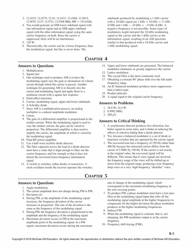
Answers to Problems 1. mf = 12 kHz/2 kHz = 6. 2. Deviation ratio = 4 kHz/2.5 kHz = 1.6. 3. For Problem 1: mf = 6 (see Fig. 1). As shown in Fig. 5-8
in the text, there are 9 significant sidebands spaced 2 kHz apart on both sides of the carrier. Bandwidth = 2(9)(2 kHz) = 36 kHz. Using Carson’s rule, the bandwidth can be calculated:
BW = 2[ fd(max) + fm(max)] BW = 2(12 kHz + 2 kHz)
= 28 kHz
11. Phase-shift keying (PSK). 12. The higher modulating frequencies must be attenuated in
proportion to their frequency by a 1/f or low-pass filter to produce FM.
13. Both the modulation index and the deviation ratio are computed by dividing the deviation by the modulating frequency. However, the deviation ratio is calculated by using the maximum allowed deviation and modulating frequency.
14. Narrow-band FM is a system with a deviation ratio of less than π/2. The goal of NBFM is to have only one significant pair of sidebands such as an AM signal to conserve spectrum space. A deviation ratio of 0.2 achieves this result, but deviation ratios of up to about 1.67 are used in practical equipment.
15. Bessel functions. 16. A negative sign on a sideband value indicates a 180°
phase shift. 17. Noise introduces amplitude variations in an otherwise
constant amplitude signal. The noise also causes phase shifts which translate to frequency shifts which in turn are interpreted as distortion.
18. Noise is minimized by clipping off the amplitude variations so that the FM signal is a constant amplitude before demodulation.
19. The primary advantage of FM over AM is that its transmission is more reliable and superior in the presence of noise.
20. Two additional advantages of FM over AM are, first, that the capture effect helps minimize interference and, second, that efficient class C amplifiers can be used for transmitter power amplifiers.
21. Most noise consists of high-frequency spikes or pulses generated by equipment.
22. An FM transmitter can use class C amplifiers, which are more efficient power amplifiers than class A, AB, or B amplifiers, which must often be used with AM transmitters.
23. The greatest disadvantage of FM is the wide bandwidth it normally requires. This excessive use of spectrum
Figure 1
BW = 36 kHz
0.02 0.060.13
0.25
0.36 0.36
0.110.15
0.11
0.36 0.36
0.25
0.130.06 0.02
12 kHz2 kHz
= 6mf=
–0.24–0.28 –0.28
–0.24
Frequency (MHz)
162 MHz
2 kHz
fre62745_PartB_B1-B36.indd 6 5/22/15 3:39 PM
Copyright © 2016 McGraw-Hill Education. All rights reserved. No reproduction or distribution without the prior written consent of McGraw-Hill Education.
B-7
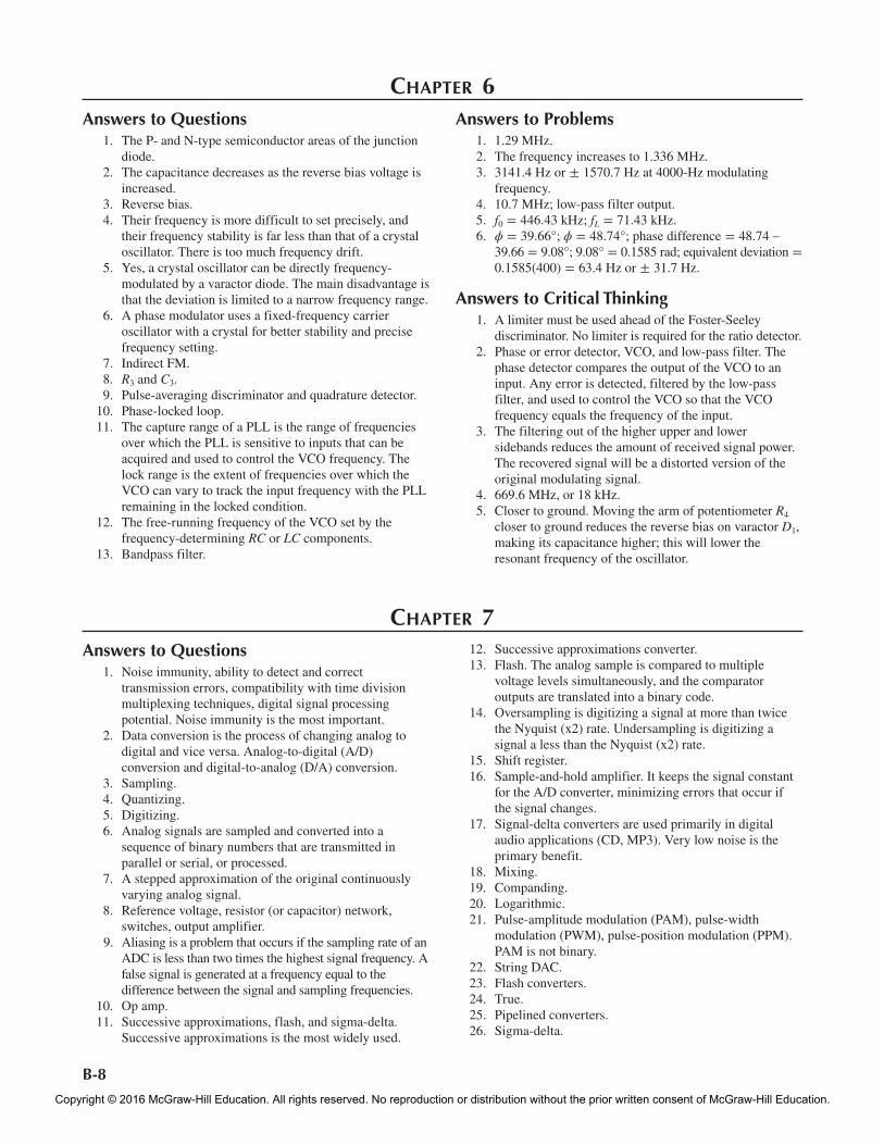
Only the single most significant sideband is produced. See Fig. 4.
3. a. See Fig. 5. b. See Fig. 6. c. BW (text Fig 5-8) = 240 kHz. d. BW (Carson’s rule) = 180 kHz. e. The BW determined by Carson’s rule is the best fit to
the actual channel assignment. 4. BW = 19 kHz by Carson’s rule; m = 6/3.5 = 1.7;
relative amplitudes: carrier = 0.43, first sideband = 0.57, second sideband = 0.25, third sideband = 0.08.
5. If the deviation ratio is 5 and the maximum deviation is 75 kHz, the maximum modulating frequency is 75/5 = 15 kHz. If this is the third harmonic, the fundamental is 15/3 = 5 kHz. A 5-kHz square could be transmitted. This would translate to a maximum data rate of 10k bits per second.
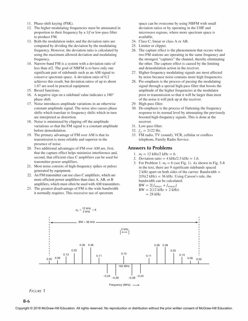
For Problem 2: mf = 1.6 (see Fig. 2). The sidebands are estimated from Fig. 5-8 in the text. There are 4 significant sidebands on each side of the carrier, spaced 2.5 kHz apart.
Bandwidth = 2(4)(2.5 kHz) = 20 kHz. Using Carson’s rule, the bandwidth can be calculated:
BW = 2[ fd(max) + fm(max)] BW = 2(4 kHz + 2.5 kHz)
= 13 kHz
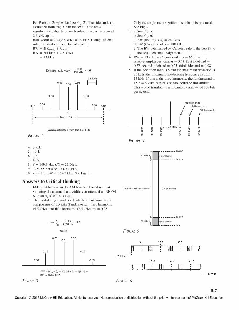
4. 3 kHz. 5. –0.1. 6. 3.8. 7. 8.57. 8. δ = 149.5 Hz, S/N = 26.76:1. 9. 3750 Ω, 3600 or 3900 Ω (EIA). 10. mf = 1.5, BW = 16.67 kHz. See Fig. 3.
Answers to Critical Thinking 1. FM could be used in the AM broadcast band without
violating the channel bandwidth restrictions if an NBFM with an mf of 0.2 was used.
2. The modulating signal is a 1.5-kHz square wave with components of 1.5 kHz (fundamental), third harmonic (4.5 kHz), and fifth harmonic (7.5 kHz). mf = 0.25.
Figure 2
0.01 0.010.06 0.06
0.23
0.560.51
0.56
0.23
Deviation ratio = mf4 kHz= = 1.6
2.5 kHz
2.5 kHz
BW = 20 kHz
fc
(Values estimated from text Fig. 5-8)
Figure 3
mf =fdfm
5 kHz3.33 kHz
= 1.5
Carrier
0.56 0.560.51
0.23 0.23
0.06 0.06
BW = 2(fm + fd) = 2(3.33 + 5) = 2(8.333)BW = 16.67 kHz
Fundamental3d harmonic
5th harmonic
48.9
925
48.9
955
48.9
985
49.0
015
49.0
045
49.0
075fc = 49 MHz
Figure 4
150-kHz modulation BW
25 kHz
25 kHz
Guard band
Guard band
fc = 99.9 MHz
100.00
99.975
99.825
99.8
Figure 5
Figure 6
fre62745_PartB_B1-B36.indd 7 5/22/15 3:39 PM
Copyright © 2016 McGraw-Hill Education. All rights reserved. No reproduction or distribution without the prior written consent of McGraw-Hill Education.
B-8
Chapter 6Answers to Questions 1. The P- and N-type semiconductor areas of the junction
diode. 2. The capacitance decreases as the reverse bias voltage is
increased. 3. Reverse bias. 4. Their frequency is more difficult to set precisely, and
their frequency stability is far less than that of a crystal oscillator. There is too much frequency drift.
5. Yes, a crystal oscillator can be directly frequency-modulated by a varactor diode. The main disadvantage is that the deviation is limited to a narrow frequency range.
6. A phase modulator uses a fixed-frequency carrier oscillator with a crystal for better stability and precise frequency setting.
7. Indirect FM. 8. R3 and C3. 9. Pulse-averaging discriminator and quadrature detector. 10. Phase-locked loop. 11. The capture range of a PLL is the range of frequencies
over which the PLL is sensitive to inputs that can be acquired and used to control the VCO frequency. The lock range is the extent of frequencies over which the VCO can vary to track the input frequency with the PLL remaining in the locked condition.
12. The free-running frequency of the VCO set by the frequency-determining RC or LC components.
13. Bandpass filter.
Answers to Problems 1. 1.29 MHz. 2. The frequency increases to 1.336 MHz. 3. 3141.4 Hz or ± 1570.7 Hz at 4000-Hz modulating
frequency. 4. 10.7 MHz; low-pass filter output. 5. f0 = 446.43 kHz; fL = 71.43 kHz. 6. ϕ = 39.66°; ϕ = 48.74°; phase difference = 48.74 –
39.66 = 9.08°; 9.08° = 0.1585 rad; equivalent deviation = 0.1585(400) = 63.4 Hz or ± 31.7 Hz.
Answers to Critical Thinking 1. A limiter must be used ahead of the Foster-Seeley
discriminator. No limiter is required for the ratio detector. 2. Phase or error detector, VCO, and low-pass filter. The
phase detector compares the output of the VCO to an input. Any error is detected, filtered by the low-pass filter, and used to control the VCO so that the VCO frequency equals the frequency of the input.
3. The filtering out of the higher upper and lower sidebands reduces the amount of received signal power. The recovered signal will be a distorted version of the original modulating signal.
4. 669.6 MHz, or 18 kHz. 5. Closer to ground. Moving the arm of potentiometer R4
closer to ground reduces the reverse bias on varactor D1, making its capacitance higher; this will lower the resonant frequency of the oscillator.
Chapter 7 Answers to Questions 1. Noise immunity, ability to detect and correct
transmission errors, compatibility with time division multiplexing techniques, digital signal processing potential. Noise immunity is the most important.
2. Data conversion is the process of changing analog to digital and vice versa. Analog-to-digital (A/D) conversion and digital-to-analog (D/A) conversion.
3. Sampling. 4. Quantizing. 5. Digitizing. 6. Analog signals are sampled and converted into a
sequence of binary numbers that are transmitted in parallel or serial, or processed.
7. A stepped approximation of the original continuously varying analog signal.
8. Reference voltage, resistor (or capacitor) network, switches, output amplifier.
9. Aliasing is a problem that occurs if the sampling rate of an ADC is less than two times the highest signal frequency. A false signal is generated at a frequency equal to the difference between the signal and sampling frequencies.
10. Op amp. 11. Successive approximations, flash, and sigma-delta.
Successive approximations is the most widely used.
12. Successive approximations converter. 13. Flash. The analog sample is compared to multiple
voltage levels simultaneously, and the comparator outputs are translated into a binary code.
14. Oversampling is digitizing a signal at more than twice the Nyquist (x2) rate. Undersampling is digitizing a signal a less than the Nyquist (x2) rate.
15. Shift register. 16. Sample-and-hold amplifier. It keeps the signal constant
for the A/D converter, minimizing errors that occur if the signal changes.
17. Signal-delta converters are used primarily in digital audio applications (CD, MP3). Very low noise is the primary benefit.
18. Mixing. 19. Companding. 20. Logarithmic. 21. Pulse-amplitude modulation (PAM), pulse-width
modulation (PWM), pulse-position modulation (PPM). PAM is not binary.
22. String DAC. 23. Flash converters. 24. True. 25. Pipelined converters. 26. Sigma-delta.
fre62745_PartB_B1-B36.indd 8 5/22/15 3:39 PM
Copyright © 2016 McGraw-Hill Education. All rights reserved. No reproduction or distribution without the prior written consent of McGraw-Hill Education.
B-9
3. 3 kHz. 4. 52.86 mV. 5. 92.06 dB. 6. 13 bits. 7. The aliased spectrum is from 52 to 68 MHz. The
optimum sampling frequency is 40 MHz.
Answers to Critical Thinking 1. Most 2-way radio is still analog (FM) including the
Family Radio Service (FM) units and Citizen’s Band radios(AM/SSB). Amateur radio is still analog with SSB and FM voice. AM and FM broadcast radio was one of the last uses to analog but with HD Radio these transmissions are now available in digital format. TV is now mostly digital. All cell phones are digital. The standard telephone is still analog from the home to the central office, but from there everything is digital. At this time virtually all communications today are digital in format.
2. The analog AM signal would be picked up by the antenna and amplified with a normal RF amplifier. The signal would then be fed to an A/D converter, which would convert it into binary data that would be sent to a DSP computer where all normal receiver functions, such as filtering for selectivity and demodulation, would be carried out. Frequency translation, as done by superheterodyne receivers, could also be implemented, although this is not necessary. The recovered signal in binary form would be sent to a D/A converter, where it would be converted into the original analog voice or music signal and then sent to an audio power amplifier where it would drive a speaker.
3. Flash or pipeline type A/D converters. These are the only A/D converters fast enough to convert video to digital.
4. Parallel transfers are faster only on short buses (< few inches). Serial is faster over very long cables (i.e., fiber optic).
27. Capacitors (D/A) converters are preferred because they use less space on an integrated circuit so can be easily integrated with other circuits. They are also less critical in adjustment and manufacturing.
28. Oversampling means that the signal to be digitized is samples at a rate many times the minimum Nyquist rate. Sigma-delta converters use this technique. It is done to provide higher resolution in the conversion process and to lower the noise level.
29. Aliasing is prevented by placing a low-pass filter at the input to the ADC with a cut-off frequency that is less than half the sampling rate.
30. Power supply voltage regulation and motor speed control. 31. DSP is the process of converting an analog signal to
binary and processing the resulting data mathematically to perform filtering and other actions, and then converting the signal back to analog.
32. A special high-speed microprocessor. 33. Multiplication and summation. 34. Von Neumann and Harvard. Von Neumann processors
use a common memory address space for both the data and the program. Harvard processors use one memory and address space for data and another for the instructions in the program.
35. Filtering, data compression, spectrum analysis, equalization, phase shifting, signal averaging.
36. The DFT and FFT output is a set of binary numbers that indicate the amplitudes of the sine wave fundamental and harmonics that make up the signal and another set of binary numbers that indicate the phase of each harmonic component.
37. Finite impulse response (FIR) and infinite impulse response (IIR) filters. The FIR filter is nonrecursive, and the IIR filter is recursive (i.e., it uses feedback).
38. Spectrum analysis.
Answers to Problems 1. 7 MHz. 2. 4095 increments of 1.221 mV.
Chapter 8 Answers to Questions 1. Crystal oscillator or frequency synthesizer, buffer
amplifier, frequency multiplier, power amplifiers, modulator. Some transmitters may include a mixer.
2. Low-power AM or any DSB/SSB transmitter. 3. 180°. 4. Signal bias. 5. Crystal oscillators may be more precisely set to a
specific frequency, but more important, the frequency remains more constant and stable over time with variations in temperature, supply voltage, and so on.
6. Add a variable capacitor in series or parallel with the crystal.
7. By changing the frequency division ratio. 8. A prescaler is a high-frequency divider circuit, usually
in IC form, that is connected between the VCO output and the input to the programmable frequency divider
used in the feedback loop of a PLL. It is used because programmable frequency dividers are usually not capable of operating at the higher VCO frequency.
9. The loop filter smoothes the output of the phase detector into a varying direct current to control the VCO frequency.
10. Digital-to-analog converter (DAC) and low pass filter (LPF).
11. The ROM stores binary values representing sine wave values at equal degree spacings.
12. Change the binary value in the phase increment counter. 13. Class D or E. 14. For individual transistors, 500 W or so; for multiple
transistors, several thousand watts. 15. Power-added efficiency is the ratio of the output power
of a PA less the driving power to the dc power consumed expressed as a percentage.
fre62745_PartB_B1-B36.indd 9 5/22/15 3:39 PM
Copyright © 2016 McGraw-Hill Education. All rights reserved. No reproduction or distribution without the prior written consent of McGraw-Hill Education.
B-10
Answers to Critical Thinking 1. Reference oscillator, phase (error) detector, low-pass
(loop) filter, VCO, frequency divider. The output is taken from the VCO.
2. Since a sine wave is symmetrical around its peak values and above and below zero, only one set of values from 0 to 90 degrees instead of 360 degrees is needed. The values are used directly from 0 to 90, than by accessing the same values in the reverse order, values of 90 to 180 degrees are achieved. The process is repeated for the negative half cycle but the resulting output voltage is inverted.
3. Ri = 5.5 Ω RL = 50 Ω
XL = 2RiRL − (Ri)2
= 2(5.5)(50) − (5.5)2
= 2275 − 30.25 = 2244.75 = 15.64 Ω XL = 2πf L L = XL/2πf f = 112 MHz L = 15.64/(6.28)(112 × 106) L = 22 nH (total series inductance) Value of L in network inductor = 22 nH – 7 nH (stray,
internal inductance) = 15 nH
Q = BRL
Ri
− 1 = B505.5
− 1 = 28.1 = 2.84
Xc =RiRL
XL
=5.5(50)15.64
= 17.58 Ω
Xc =1
2πfC
therefore, C =1
2πfXc
C =1
6.28(112 × 106)(17.58)=
80.85 pF (total shunt C) C in network = total C – stray C 80.85 - 22 = 58.85 pF 4. Np/NS = 0.2887. 5. Most modern digital transmitters use a form of
modulation such as OFDM, QAM or, spread spectrum that requires both amplitude and phase components be accurately amplified.
16. High efficiency, low heat generation, and simple circuits. 17. Both are switching-type amplifiers, but class D uses two
transistors and dual power supplies, whereas the class E amplifier uses a single supply and transistor.
18. An envelope tracking PA uses the recovered amplitude of the signal to be amplified to modulate the dc supply to the PA. This keeps the PA dc operating point in the optimum range for best efficiency.
19. A feedforword power amplifier generates the amplified signal with and without distortion and subtracts out the distortion(harmonics) before being sent to the output.
20. The feedback is a sample of the amplified output signal with distortion.
21. Zi = ZL. 22. A toroid is a donut-shaped magnetic core used to make
inductors, transformers, and baluns. 23. Toroids do not radiate their magnetic field like other coils.
Most of the magnetic field is confined to the core. The high permeability of the core permits higher-value inductors to be made with fewer turns of wire than in an air core coil.
24. Filtering out harmonics. 25. Autotransformer. 26. Balun. A common application is to convert balanced
outputs to unbalanced (grounded) loads or unbalanced outputs to balanced (ungrounded) loads.
27. So that the amplifier will amplify signals over a wide frequency range.
28. Transformers. 29. 1:1, 1:4, 1:9, 1:16, 1:25. 30. Higher Q or Q selected for a specific bandwidth.
Improved selectivity and minimized harmonics.
Answers to Problems 1. 206.4 MHz. 2. 30 ppm. 3. 25.005 MHz. 4. 8.625 MHz. 5. 1627. 6. 100 kHz. 7. 132 MHz, 50 kHz. 8. .08789 degrees. 9. 48,828.125 Hz. 10. 14.296875 MHz. 11. 72 W. 12. The network of Fig. 7-39(b) in the text is applicable;
L = 31.8 nH, C = 47.1 pF. 13. L = 48.1 nH, C = 174.2 pF. 14. L = 176.92 nH, C1 = 15.76 pF, C2 = 34.18 pF. 15. 450 Ω. 16. 7.071 to 1.
Chapter 9Answers to Questions 1. The bandwidth increases. 2. The simplest receiver is an antenna, a selective circuit
and a demodulator. 3. The higher-frequency sidebands would be greatly
attenuated, thereby distorting the signal.
4. The selectivity of a receiver is usually determined by the IF amplifier filters or in a direct conversion receiver by the filters following the downconverting mixers.
5. The shape factor of 1.8 represents the best selectivity. 6. Tuned radio frequency (TRF). 7. Superheterodyne. 8. Mixer and local oscillator.
fre62745_PartB_B1-B36.indd 10 5/22/15 3:39 PM
Copyright © 2016 McGraw-Hill Education. All rights reserved. No reproduction or distribution without the prior written consent of McGraw-Hill Education.
B-11
9. IF amplifier. 10. Automatic gain control (AGC). 11. Local oscillator frequency and input (received) signal
frequency. 12. IF amplifier, RF amplifier. 13. Image. 14. Poor (too broad) selectivity in the RF amplifier or
receiver input tuned circuits. 15. A dual-conversion superheterodyne has two mixers and
local oscillators and a first and second IF. A dual-conversion superheterodyne has better image rejection than a single-conversion receiver.
16. Ensure proper selectivity in the receiver front end. 17. f1, f2, f1 + f2, f1 – f2. 18. Doubly balanced mixer. 19. Dual-gate MOSFET. 20. Amplitude modulation. 21. An image reject mixer uses two mixers and the concepts
of the phasing method of SSB to cancel images but passing the desired signal.
22. Good frequency stability. 23. Frequency synthesizer. 24. To down-convert the VCO to a lower frequency within
the range of the variable modulus dividers used to change the frequency.
25. Manufactured or industrial, extraterrestrial (solar, cosmic), and atmospheric noise.
26. A direct conversion or zero IF receiver is a superheterodyne where the local oscillator is set to the signal frequency so that the mixer produces a difference frequency equal to the baseband signal.
27. A software defined radio is one that converts the incoming signal to an IF. The IF output is digitized in an ADC and the resulting signal is digitally processed (filtering, demodulation, etc.). High speed ADC and digital signal processing (DSP) computers make this possible.
28. Quadrature mixers in a ZIF receiver are necessary in order to preserve any frequency or phase variations in the signal due to modulation. DSP algorithms for demodulation and other processes require quadrature signals for computation.
29. Thermal noise, shot noise, 1/f or flicker noise, transit time noise, correlated noise (intermodulation modulation).
30. Lightning. 31. Automobile ignitions, fluorescent lights, motors, relays,
and solenoids. 32. Thermal or Johnson noise. 33. Power decibels. 34. The noise increases with temperature. 35. It decreases the noise level. 36. Shot noise, flicker (1/f ) noise, transit-time noise. 37. False. 38. Signal, noise, and distortion. 39. The input stage, usually an RF amplifier, contributes the
most noise in terms of its relationship to the received signal level. The mixer is the noisiest circuit in the receiver.
40. An RF amplifier boosts signal level before it is applied to the usually noisy mixer but adds noise of its own. If a very-low-noise RF amplifier can be used, it is advantageous
to boost signal level before the mixer. If the signal level is usually high, the RF amplifier may not be needed.
41. GASFETs or MESFETs. 42. Diode, double balanced, singly balanced. 43. Double-tuned coupled circuits, crystal, ceramic, or SAW
filters. 44. AWGN is a standard random noise created for the
purpose of testing receivers and comparing selectivity. 45. Limiter. 46. Limiting is allowed in FM receivers that have a
demodulator that must have a fixed amplitude input signal for proper operation.
47. Collector current. 48. 100 dB. 49. Automatic gain control (AGC). 50. In forward AGC, increasing the collector current of an
IF amplifier transistor decreases the gain. In reverse AGC, increasing the collector current increases the gain.
51. By changing the emitter current. 52. Squelch; muting. 53. The local oscillator frequency is equal to the received
signal frequency. 54. CTCSS is a squelch system that is activated only by the
receipt of a unique tone signal which provides channel privacy and security.
55. CW and SSB. 56. An SDR divides the received signal into two paths, one
in-phase (I) and one in quadrature (90 degrees) so that the signal may be demodulated by DSP.
57. Crystal, ceramic, and SAW filters. 58. In a single chip transceiver, the frequency of operation
is usually changed by sending a unique binary code to the frequency synthesizer which operated both the transmitter and receiver. The unique code is usually derived from an internal embedded controller according to some frequency scheme associated with the wireless service involved.
59. Power supply. 60. Power supply, local oscillators or frequency synthesizer,
IF or sideband filter. 61. Mixer. 62. Transmitter carrier, first local oscillator, second local
oscillator. 63. A ZIF receiver cannot in a basic form demodulate FM or
PM. FM and PM can be used if the receiver is implemented with two mixers using quadrature (90° phase shift) local oscillator signals. The two mixer outputs together contain the frequency and phase information used to recover FM or PM.
64. Mixing, filtering, demodulation, equalization. 65. The 10.7-MHz ceramic filter FIL 1. 66. As the voltage becomes more positive, the capacitance of
the varactor D1 decreases. Varactor D1 is in series with capacitor C14. This combination resonates with L 6. As the capacitance of D1 decreases, the total capacitance decreases and the resonant frequency increases.
67. MC 1350 IF IC. 68. Signal-derived. 69. No. 70. No. 71. It increases.
fre62745_PartB_B1-B36.indd 11 5/22/15 3:39 PM
Copyright © 2016 McGraw-Hill Education. All rights reserved. No reproduction or distribution without the prior written consent of McGraw-Hill Education.
B-12
Answers to Critical Thinking 1. Lower temperature produces less thermal noise. 2. First local oscillator = 515.6 MHz, second local
oscillator = 45.5 MHz, transmitter carrier oscillator = 39.216667 MHz.
3. Connect a counter to pin 6 or 7 of the NE602 mixer, which is the local oscillator output. Subtract 10.7 MHz from the counter reading to get the received frequency.
4. The PC video monitor display of an SDR consists of a frequency spectrum plot, a waterfall display, and numerical frequency display plus any controls (volume, etc.).
5. 107.7 dB. 6. The IF is usually the difference between the local
oscillator frequency and the received signal. In this case, it is zero. However, the signal has sidebands at 10.8 MHz ± 700 Hz, which will beat with the local oscillator to produce a 700-Hz output from the diode detector. This is called a direct conversion receiver. The IF is the original modulating signal. If the signal is voice, the IF amplifier is a selective audio amplifier.
7. 300 MHz minimum.
72. Pin 5 of U3-b. 73. 10.7 MHz. Input to the ceramic filter FIL 1. 74. U2.
Answers to Problems 1. 6 kHz. 2. 358.38 kHz. 3. 18.06 and 17.94 MHz. 4. 900. 5. 2.4. 6. 4.5 MHz. 7. 46 MHz. 8. First IF = 9 MHz; second IF = 400 kHz. 9. 27, 162, 189, 351 MHz. 10. 27 MHz is the most likely IF. 11. 390 MHz. 12. 3.6875 MHz, 12.5 kHz. 13. 3.44, 5.37 dB. 14. 1.43 µV. 15. Microwave frequencies. 16. 232 K. 17. -126 dBm means the best selectivity. 18. -151 dBm.
Chapter 10Answers to Questions 1. No; it is the process of transmitting multiple signals over
a single channel. 2. Economics. 3. Demultiplexer. 4. Signals to be multiplexed are used to modulate
subcarriers of different frequency. All are mixed together and transmitted in a common channel bandwidth.
5. Linear mixer or analog summer. 6. Linear mixer. 7. FM. 8. Missile and aircraft testing, space exploration, industrial
monitoring and control. 9. Spatial multiplexing allows multiple signals to use the
same frequency but prevents interference between them by using low power and directional antennas.
10. L + R. 11. L + R, or monaural signal; L – R; 19 kHz pilot carrier;
and SCA. 12. AM, DSB. 13. FM. 14. A bandpass filter centered on the subcarrier frequency. 15. The signals are sampled sequentially, and the samples
transmitted by interleaving them over time. 16. Pulse-amplitude modulation (PAM). 17. Clock recovery circuits. 18. Synchronizing signals and clock recovery circuits
ensure that the receiver stays in step with the transmitted signals.
19. Frame.
20. Low-pass filter. 21. MOSFET. 22. A binary code representing the desired channel is
contained in a counter or register which is decoded. The decoder output enables the specific MOSFET.
23. A PAM signal is transmitted by having the pulses amplitude modulate a carrier which is then amplified by a linear power amplifier. Alternately, the PAM may be converted to PCM for transmission by some frequency or phase modulation scheme.
24. Phase-locked loop. 25. By converting the analog signals to digital with an A/D
converter. 26. Codec. 27. 8 kHz. 28. 8 bits. 29. Better noise immunity and more easily reconstructed
binary signals distorted by the transmission process. 30. 193. 31. Baseband techniques are used to transmit T-1 signals;
that is, the digital data is placed on the medium (twisted-pair cable, coax, fiber-optic cable, or audio link), as opposed to the signal being used to modulate a carrier.
32. Half-duplexing means two way transmission where one party transmits and the other listens. Full-duplex means that both parties may transmit and receive at the same time.
33. Frequency division duplexing divides a segment of spectrum into channels some of which are assigned for transmission at one end and reception at the other end and vise versa. Time division duplexing defines different time slots in transmissions that are for transmission or reception.
fre62745_PartB_B1-B36.indd 12 5/22/15 3:39 PM
Copyright © 2016 McGraw-Hill Education. All rights reserved. No reproduction or distribution without the prior written consent of McGraw-Hill Education.
B-13
Answers to Critical Thinking 1. 2.78 µs. 2. 384, 2.048 MHz. 3. Yes. Separate binary data sources may modulate
subcarriers on different frequencies. The subcarriers are summed, and the resulting composite transmitted as an FDM signal.
34. FDD requires much more spectrum where as TDD can use only a single channel. TDD is more complex because of the timing and synchronization requirements of the method.
Answers to Problems 1. 66. 2. 28 kHz. 3. Bit rate 1.544 MHz, 24 channels (T1). Bit rate 44.736 MHz, 672 channels (T3).
Chapter 11Answers to Questions 1. The telegraph. 2. Morse code. 3. You cannot distinguish between uppercase and
lowercase letters with Morse code. 4. C = — · — · 7 = — — · · · ? = · · — — · · 5. Baudot code. 6. N. 7. ASCII. 8. To ring a bell, transmit the BEL code 0000111. 9. Serial and parallel. 10. Start and stop bits. 11. Baud rate. A symbol is any change in the transmitted
signal during a bit interval such as amplitude, frequency, or phase.
12. Each symbol can represent two or more bit combinations.
13. 2-bits per baud. 14. Synchronous transmission is faster because start and
stop bits are not used on each transmitted byte; the total number of bits to be transmitted in a given time is thus less.
15. The message words are sent serially in a fixed format of a specific number of words in a block. A preamble precedes the block, and a postamble error code ends the transmission.
16. Space (0) and mark (1). 17. NRZ. 18. Two or more successive binary 0 or 1s. 19. Bipolar RZ and Manchester. 20. No average DC buildup on the transmission line. 21. Manchester, biphase. 22. High speeds are obtained by using a small modulation
index and prefiltering the binary signal. 23. Number of coding levels and the transmission speed
(baud). 24. True. 25. Higher bps data rate. 26. UART, scrambler, modulator, equalizer, line interface,
adaptive receive equalizer, demodulator, descrambler, microcontroller.
27. Modems are needed to convert digital signals to analog signals and vice versa to make them compatible with the standard voice-grade telephone system. Modems are used with any computer that must communicate with another computer over long distances using the telephone system.
28. 53 kbps. 29. DMT (OFDM). 30. 1.536 Mbps (max) 384 kbps (min). 31. A scrambler ensures that long strings of binary 0s or 1s
are broken up into replacement codes with few successive 0 or 1 bits.
32. DOCSIS is Data Over Cable Service Interface Specification, the cable TV industry standards for transmission of TV and data.
33. 6 MHz. 34. Upload QDSK, 10 Mbps; downloads 64-QAM,
30 Mbps. 35. Balanced modulator. 36. Balanced modulator. 37. A carrier recovery circuit, usually a phase-locked
loop. 38. Differential BPSK. 39. XNOR gate and a 1-bit delay (flip-flop). 40. Four. 41. Two. 42. Four. 43. Yes. 44. Yes. 45. Shift register. 46. A two- to four-level converter or D/A converter. 47. AM and PSK. 48. 8 VSB. 49. Trellis code modulation is a form of QAM, used at data
rates of 9600 bps or above, that incorporates a coding scheme that makes error detection and correction faster and easier. It is used because at faster data rates over the telephone system the bit error rate is much higher than at rates less than 9600 bps.
50. 256 QAM is 8 bits per baud. 51. 64 QAM. 52. The highest level modulation in DOCSIS 3.1 is
4096 QAM.
fre62745_PartB_B1-B36.indd 13 5/22/15 3:39 PM
Copyright © 2016 McGraw-Hill Education. All rights reserved. No reproduction or distribution without the prior written consent of McGraw-Hill Education.
B-14
95. The last field in a protocol frame is usually a block check sequence or CRC for error detection.
96. Block. 97. They begin with a series of synchronizing bits or words
in order to set up the receiver’s clock recovery circuits prior to receiving the data.
98. Bisync, SDLC, HDLC. 99. A CRC word. 100. Interoperability refers to the ability of one type of
equipment to operate compatibly and communicate with the equipment of another manufacturer.
101. Use protocols based on the OSI layers. 102. Applications, presentation, session, transport, network,
data link, physical. 103. Physical, data link, network, and applications.
Answers to Problems 1. EBCDIC. 2. 14,285.71 bps = 14.3 kbps. 3. 69.44 µs. 4. 2,500,000. 5. 60 kbps. 6. 179.89 kbps. 7. 278.95 Mbps. 8. 175 Hz. 9. 8 × 10⁻⁶. 10. a. 0; b. 1; c. 0; d. 0. 11. Hamming code bits = 0010; complete code =
011001101010. 12. 1.818.
Answers to Critical Thinking 1. A temperature sensor such as a thermistor or resistive
temperature device (RTD) monitors the temperature. The resulting analog signal developed by this sensor is amplified and sent to an A/D converter. This signal is serialized and packaged into a protocol packet by a microprocessor. It is then sent to modulate a low-power radio transmitter with antenna.
The receiving antenna picks up the signal and recovers the original digital signal, which is then put back into parallel form and sent to an interface on the computer. A program in the computer reads the data from the interface and stores it in memory. The program takes the data word and processes it so that it is displayed as the correct temperature on the video screen of the computer.
2. Cellular telephone. Many phones could share a common band simultaneously. The conversations would be secure and private.
3. Remote controls for TV sets, garage doors, and car doors, radio-controlled airplanes or cars—all via AC power lines.
4. ADSL and OFDM have to use DSL because it eliminates an enormous number of complex circuits.
5. Spread spectrum and OFDM are spectrally efficient because the disperse the very high data rate signals over a broad spectrum that is typically less spectrum than other methods use for the same data rate.
53. The process of modifying an intelligence signal in such a way that its spectrum is spread over a wide frequency range rather than being confined to a narrow single-channel bandwidth.
54. Frequency-hopping and direct-sequence SS. 55. A frequency synthesizer. 56. A pseudorandom sequence generator. 57. False. 58. Random background noise. 59. The identifying characteristic of a spread spectrum
signal is the unique pseudorandom code being used. 60. Dwell time. 61. A shift register with XOR feedback or a specially
programmed microcomputer. 62. The PSN signal is a unique binary code sequence used
for each station operating over a shared spectrum. It allows one station to be distinguished from another.
63. XOR. 64. True. 65. BPSK. 66. Synchronizing the receiver to the desired signal. 67. Correlation. 68. Data security and resistance to jamming or interference
from other signals. 69. Yes. 70. Cellular telephone, satellite, and radar. 71. Voice signals are converted to serial digital data before
they are sent to the SS equipment. 72. Code division multiple access (CDMA). 73. Redundancy, special codes, encoding methods, parity,
block-check character, cyclical redundancy check. 74. Repeat the transmission until it is correctly received. 75. Reed Solomon. 76. Noise and/or weak signal. 77. Bit error rate (BER). 78. RZ-AMI. 79. Parity bit. 80. Block-check code, or BCC. The corresponding bits in
each word are added without carry to form the block-check character.
81. Vertical redundancy check. 82. XOR gate. 83. Longitudinal redundancy check. 84. A block of data is treated as if it were one very large
binary number. It is divided by a smaller binary number called the generating function. The resulting quotient is abandoned, and the remainder is retained. The remainder is the CRC.
85. A shift register with feedback through XOR gates. 86. True. 87. A CRC is generated at the receiver using the received
data block. It is then compared to the received CRC. If the two match, the data is correct.
88. Reed Solomon. 89. The sum is zero (0000), indicating no errors in a bit
position. 90. Trellis, Viterbi, turbo (recursive) codes. 91. Protocol. 92. Handshaking. 93. XON and XOFF. 94. Xmodem.
fre62745_PartB_B1-B36.indd 14 5/22/15 3:39 PM
Copyright © 2016 McGraw-Hill Education. All rights reserved. No reproduction or distribution without the prior written consent of McGraw-Hill Education.
B-15
Chapter 12Answers to Questions 1. To permit individual PCs to communicate, share
peripherals, and exchange software. 2. The MAN is smaller. 3. A cable TV network or a large company. 4. About 1000 users per LAN. 5. Node. 6. Star, ring, bus. 7. Ring and bus. 8. Server. 9. The telephone system is a WAN. The fiber optic
backbones of the Internet are WANs. 10. Fiber optic cable. 11. E-mail. 12. A SAN is a storage area network, a system made up of a
redundant array of independent disks (RAID) or just a bunch of disks (JBOD) forming a storage facility for company or organization that can be accessed by servers and users via a high speed network.
13. Wireless is the normal medium used in a PAN. 14. The main advantage of a mesh network is its reliability
because of one node in the network is disabled or out of range an alternate path can be formed or taken to ensure communications.
15. Coaxial cable is self-shielding and thus less subject to noise pickup.
16. Unshielded twisted pair (UTP) and shielded twisted pair (STP).
17. AWG 22, 24, 26. 18. RJ-45. 19. Network interface card. 20. A transceiver or repeater. 21. Bridge. 22. An Ethernet switch connects or disconnects individual
PCs or segments of a LAN together as needed. If a PC or segment of LAN is not addressed, it is disconnected. This reduces the load on the bus and collisions, thereby greatly improving transmission speed.
23. A hub is a centralized connection point for attaching individual PCs to the network bus.
24. PoE means power over Ethernet. This is a variation of the Ethernet standard that permits DC power to be distributed over the twisted pair cable that carries the high speed data. It makes remote access points for wireless LANs to be connected to a LAN without access to AC power in remote locations.
25. 10 Mbps, 100 Mbps, 1 Gbbps, 10 Gbps, 40 Gbps, 100 Gbps.
26. Bus. Star in the newer systems. 27. Manchester. It is used because clock recovery is easy. 28. Twisted pair and fiber optic cable. 29. Carrier sense multiple access with collision detection
(CSMA/CD). 30. Ethernet nodes complete (contend) for the bus. If one
node transmits, no others can transmit until the first transmission is complete. If two stations try to transmit at the same time, a collision occurs and both stations stop sending. They wait a random time and start
transmitting again. The one waiting the shorter time captures the bus first.
31. 1500 bytes. 32. 100 MHz. 33. Layers 1 and 2. 34. 1 Gigabit Ethernet over copper cable is achieved by
encoding the data bits into 2-bits per baud and transmitting over four parallel twisted pairs in a CAT5 cable at 250 Mbps each for a total of 1 Gbps.
35. Maximum range fiber optic cable 1 Gbps: 10km 10 Gbps: 40 km distance depends on the wavelength of the laser transmitters, shorter wavelengths (850 and 1310 nm) for the shorter distances and longer wavelength (1550 nm) for the longer distances.
36. Backbones connecting large LANs or small metro area networks.
37. 8B/10B. Makes clock recovery easier and permits implementation of error detection and correction.
38. Passive optical networks (PON). 39. Single mode fiber (SMF) and multi-mode fiber (MMF). 40. Unshielded twisted pair (UTP). 41. The MAC address is a 48-bit address assigned to
Ethernet interfaces to be used in Layer 2 of the OSI model communications protocol.
42. A back plane is a printed circuit board that interconnects connectors into which other boards are plugged. A router is an example.
43. Four parallel lanes of 10 Gbps paths are combined to produce 40 Gbps. Ten 10 Gbps lanes are combined to produce a 100 Gbps path.
44. The line rate of a high speed path is different from the actual raw data rate because of the extra overhead bits of forward error correction codes added for reliability.
45. True. 46. Carrier Ethernet software. 47. A data center is a facility with multiple servers,
switches, and routers that form networks and facilitate network communications.
Answers to Problems 1. 100 Mbps; t = 1/100 × 106 = 0.01 × 10–6 = 0.01 µs = 10 ns. 2. 10GH. 3. 12.5 Gbps.
Answers to Critical Thinking 1. Factory automation, in which multiple computers
controlling robots, machine tools, computer vision systems, and other equipment are usually networked.
2. Number of nodes on the network, the amount of traffic or activity on the LAN, and the access method used.
3. The 8B/10B encoding converts each byte to 10-bit words. It takes longer to transmit the two extra bits and that slows the over transmission.
4. Yes, a single fiber can support 40 Gbps or 100 Gbps over shorter distances using NRZ or over longer distances using multiplexing or modulation methods.
fre62745_PartB_B1-B36.indd 15 5/22/15 3:39 PM
Copyright © 2016 McGraw-Hill Education. All rights reserved. No reproduction or distribution without the prior written consent of McGraw-Hill Education.
B-16
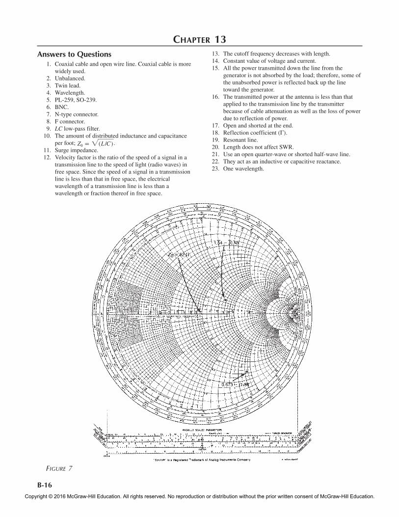
Figure 7
Chapter 13Answers to Questions 1. Coaxial cable and open wire line. Coaxial cable is more
widely used. 2. Unbalanced. 3. Twin lead. 4. Wavelength. 5. PL-259, SO-239. 6. BNC. 7. N-type connector. 8. F connector. 9. LC low-pass filter. 10. The amount of distributed inductance and capacitance
per foot; Z0 = 2(L /C ) . 11. Surge impedance. 12. Velocity factor is the ratio of the speed of a signal in a
transmission line to the speed of light (radio waves) in free space. Since the speed of a signal in a transmission line is less than that in free space, the electrical wavelength of a transmission line is less than a wavelength or fraction thereof in free space.
13. The cutoff frequency decreases with length. 14. Constant value of voltage and current. 15. All the power transmitted down the line from the
generator is not absorbed by the load; therefore, some of the unabsorbed power is reflected back up the line toward the generator.
16. The transmitted power at the antenna is less than that applied to the transmission line by the transmitter because of cable attenuation as well as the loss of power due to reflection of power.
17. Open and shorted at the end. 18. Reflection coefficient (Γ). 19. Resonant line. 20. Length does not affect SWR. 21. Use an open quarter-wave or shorted half-wave line. 22. They act as an inductive or capacitive reactance. 23. One wavelength.
fre62745_PartB_B1-B36.indd 16 5/22/15 3:40 PM
Copyright © 2016 McGraw-Hill Education. All rights reserved. No reproduction or distribution without the prior written consent of McGraw-Hill Education.
B-17
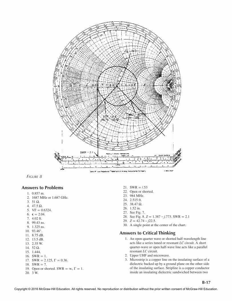
Figure 8
Answers to Problems 1. 0.857 m. 2. 1687 MHz or 1.687 GHz. 3. 51 Ω. 4. 47.5 Ω. 5. VF = 0.6324. 6. ϵ = 2.04. 7. 4.02 ft. 8. 99.43 ns. 9. 1.325 ns. 10. 93.46°. 11. 8.75 dB. 12. 13.5 dB. 13. 2.35 W. 14. 52 Ω. 15. 1.444. 16. SWR = 1. 17. SWR = 2.125, Γ = 0.36. 18. SWR = 7. 19. Open or shorted. SWR = ∞, Γ = 1. 20. 3 W.
21. SWR = /.53 22. Open or shorted. 23. 984 MHz. 24. 2.515 ft. 25. 38.47 Ω. 26. 1.52 in. 27. See Fig. 7. 28. See Fig. 8. Z = 1.387 – j.773. SWR = 2.1 29. Z = 42.74 – j22.5. 30. A single point at the center of the chart.
Answers to Critical Thinking 1. An open quarter wave or shorted half-wavelength line
acts like a series tuned or resonant LC circuit. A short quarter-wave or open half-wave line acts like a parallel resonant LC circuit.
2. Upper UHF and microwave. 3. Microstrip is a copper line on the insulating surface of a
dielectric backed up by a ground plane on the other side of the insulating surface. Stripline is a copper conductor inside an insulating dielectric sandwiched between two
fre62745_PartB_B1-B36.indd 17 5/22/15 3:40 PM
Copyright © 2016 McGraw-Hill Education. All rights reserved. No reproduction or distribution without the prior written consent of McGraw-Hill Education.
B-18
cable will be a nearly sinusoidal signal at 10 MHz. Some of the harmonic energy will still be present but in lower levels, so that the output wave will bear some resemblance to a square wave but will be highly filtered until it is almost a sine wave.
6. A shorted half wavelength of transmission line acts like a series resonant circuit. Connecting this transmission line across the receiver front end will cause it to short out the interfering frequency of 102.3 MHz. One half wave at 102.3 MHz is 492/102.3 = 4.8 ft × velocity factor of 0.66 = 3.17 ft.
ground planes on opposite sides of the dielectric. Stripline is preferred because it does not radiate, but it is harder to make.
4. Z = 2.6 + j1.1 = 130 + j55; SWR = 3. 5. Refer to text Fig. 13-14. Two hundred feet of RG-58A/U
coaxial cable has a –3-dB cutoff frequency of approximately 8 MHz. Therefore, a 10-MHz square wave, which is made up of a 10-MHz fundamental sine wave and all odd harmonics, will be attenuated and distorted. The third, fifth, seventh, and higher harmonics will be greatly attenuated. The output of the coaxial
Chapter 14 Answers to Questions 1. A radio wave is the combination of electric and
magnetic fields varying at the signal frequency. 2. Maxwell’s equations state the relationship and
interaction of the electric and magnetic fields that are radiated from an antenna. These equations state that an electric field varying over time sets up a magnetic field which, in turn, sets up an electric field, both of which are propagated in space without energy loss.
3. The electric and magnetic fields set up by the antenna are at right angles to one another, and both are at a right angle to the direction of propagation.
4. The orientation of the electric field determines the polarization—vertical, horizontal, or circular.
5. Vertical. 6. Antenna reciprocity means that an antenna will receive
as well as transmit at the operating frequency. 7. Hertz or dipole. One-half wavelength. 8. A transmission line connects the antenna to the receiver
or transmitter. The most common transmission line is coaxial cable.
9. One-half wavelength = 492/fMHz. 10. 73 Ω. 11. Height of the antenna above ground and length. 12. At resonance, resistive (73 Ω); above resonance,
inductive; below resonance, capacitive. 13. Antenna bandwidth is a function of antenna conductor
size; the larger the conductor the lower the Q and the wider the bandwidth.
14. See Fig. 14-15 in the text. Donut-shaped. 15. Directivity refers to how an antenna “shapes”
electromagnetic waves so that they are emitted (or received) in a specific direction in relation to the antenna conductors.
16. Signal strength in relative power or decibels over a given azimuth.
17. Antenna gain is the apparent signal strength increase over an isotropic antenna or dipole caused by the directivity of the antenna that comes from concentrating or focusing the signal into narrow beams.
18. An isotropic radiator is an imaginary point source of electromagnetic energy that radiates equally in all directions.
19. 1.64 power gain or 2.15 dB.
20. Antenna gain is expressed as a power ratio or in decibels referenced to an isotropic source or a dipole.
21. Effective radiated power. This is the apparent power radiated by a directional antenna which is a product of the power applied to the antenna and the antenna gain.
22. A folded dipole is a continuous-loop conductor formed into a half-wavelength center-fed dipole. It has a 300-Ω characteristic impedance that makes it a good match to 300-Ω twin-lead cable and broader bandwidth.
23. Marconi and ground plane. 24. A circle. 25. Omnidirectional. 26. Radials. 27. A counterpoise array of conductors. 28. 50-Ω coaxial cable. 29. Bidirectional. 30. An antenna that transmits essentially in one direction or
over a narrow range of azimuth. 31. A directional antenna amplifies because it focuses the
radiated energy into a narrow beam or beams. 32. A directional antenna with gain usually consists of at
least two separate conductors that together help direct or focus the radiation. Antennas longer than one-half wavelength also exhibit gain and directivity.
33. Driven and parasitic. 34. Driven element, reflector, and director. 35. Reflector and director. 36. Theoretically there is no upper limit, but the number is
usually limited by the size of the antenna at the operating frequency and any resulting physical restrictions. The desired beamwidth, gain, and front-to-back ratio are also factors.
37. 20 to 40°. 38. Number or directors and their spacing. 39. The front-to-back ratio is the ratio of the power of the
signal sent forward in the main directivity pattern of the antenna to the power delivered to the opposite (180°) end of the antenna.
40. True. 41. Horizontal. 42. Broadside, collinear, end fire. 43. The resulting radiation pattern will resemble a very
narrow and tall “figure 8” design. 44. Yes.
fre62745_PartB_B1-B36.indd 18 5/22/15 3:40 PM
Copyright © 2016 McGraw-Hill Education. All rights reserved. No reproduction or distribution without the prior written consent of McGraw-Hill Education.
B-19
75. Multipath signal reflections. 76. Rayleigh fading. 77. It requires multiple sets of transceivers and multiple
frequencies. 78. Spatial diversity uses two or more antennas spaced as far
apart as practical so that each receives a slightly different version of the signal. The best signal is selected or the signals are combined.
79. Wideband signals.
Answers to Problems 1. 0.1 wavelength, 20 Ω; 0.3 wavelength, 90 Ω
(see text Fig. 14-12). 2. 468/16 = 29.25 ft. 3. 468/27 = 17.333 MHz; bandwidth = 520 kHz to 1.04 MHz. 4. Horizontal. 5. 50 or 75-Ω coaxial cable. 6. 12.56 W. 7. 1.822 ft. 8. 0.2 ft = 6.24 in. 9. 1.65 ft. 10. One-half wavelength = 1.734 ft. 11. 24 in. 12. 14.14 mi. 13. 23.5 mi. 14. 179.4 dB. 15. 8.15 dB. 16. 9.09 ft.
Answers to Critical Thinking 1. The antenna made with tubing has a wider bandwidth. 2. Antenna length = 400 tan 30° = 231 ft;
f = 234/231 = 1.01 MHz. 3. The center conductor attaches at the base of the vertical
antenna element; the shield braid is connected to a good earth ground, radials, or a counterpoise array of conductors.
4. The quarter-wave vertical and dipole perform in exactly the same way. Polarization is different, but gain is the same.
5. The impedance is 36.5 Ω. The angle or “droop” of the radials affects the impedance, as does the height of the antenna above ground.
6. Add an inductive loading coil at the base or in the center of the vertical radiator.
7. Add a capacitor in series with the antenna, or add a capacitive top hat.
8. 20° at the –3-dB down points. Front-to-back ratio = 0 dB – 24 dB = 24 dB; x = 2 log (203/dB) = 2.013;
gain = 10x = 20.13 dB. 9. 0.637 nW, 178.4 µV. 10. 188.2 mi. 11. Wavelength = 984/f = 984/902 = 1.09 m; 5/8 wavelength = 0.625 wavelength = 0.682 m or 26.84 in. 12. Since the transmitter cannot be accessed or changed in
any way, some improvements can be made at the receiver: Add a low-noise RF amplifier to the receiver front end, add a directional gain antenna pointed at the transmitter, increase antenna height, and/or add bandpass filtering that might improve the signal-to-noise ratio.
45. Log periodic. 46. Very wide bandwidth. 47. 50 Ω. 48. To achieve low SWR and maximum power transfer to
the antenna. 49. Toroid balun. 50. Q section. 51. 4:1 or 1:4. 52. An antenna tuner consists of one or more variable
capacitors and inductors that may be connected in a variety of configurations to match transmitter to the load, reduce SWR, and increase transmitted power.
53. Tune for low SWR and maximum output power. 54. Radio signals are reflected by any conductive surface.
The better the conductor, the greater the amount of reflection and the lesser the amount of signal absorbed by the reflecting surface.
55. Theoretically no, but in the real world vertically polarized waves will induce a small signal into a horizontal antenna.
56. Circular polarization is the orientation of a radio wave so that its electric and magnetic fields continuously rotate in a circle. Clockwise rotation is called right-hand circular polarization (RHCP), and counterclockwise rotation is called left-hand circular polarization (LHCP).
57. Yes, but reception will not be optimum. 58. Refraction is the bending of radio waves caused by the
waves passing from the atmosphere into differently charged layers of the ionosphere.
59. Diffraction is the bending of light or radio waves around the edges of objects blocking the waves. Diffraction is beneficial in that it permits communications when obstacles might prevent propagation.
60. Ground, sky, and space waves. 61. Ground wave or surface wave. The waves must be
vertically polarized. 62. 30 kHz to 3 MHz. 63. Sky wave. 64. 3 to 30 MHz. 65. The ionosphere is an area 30 to 250 mi above the earth
which has been highly ionized by the sun, making it a form of conducting medium that affects radio waves.
66. The F layers. 67. False. It reflects or bends them in such a way that it
looks as if the waves have been reflected. 68. Multiple-skip transmission; the wave refracted back to
earth is reflected by the earth back to the ionosphere and again refracted back to earth for another reflection, and so on.
69. The angle of entry into the ionosphere and the frequency of the wave.
70. A space or direct wave. 71. VHF, UHF, and microwave, or approximately 30 MHz
and above. 72. Increase the height of the transmitting and/or receiving
antenna. 73. Use a repeater or a chain of retransmitting repeaters. 74. A repeater is usually located at a high point to permit
maximum receiving and transmitting distances. It consists of a receiver that picks up signals on one frequency, demodulates them, and remodulates a high-power transmitter on another frequency for retransmission.
fre62745_PartB_B1-B36.indd 19 5/22/15 3:40 PM
Copyright © 2016 McGraw-Hill Education. All rights reserved. No reproduction or distribution without the prior written consent of McGraw-Hill Education.
B-20
Chapter 15 Answers to Questions 1. Email, file transfer, accessing websites, searches,
e-commerce, IPTV, and VoIP. 2. The domain is an Internet service provider (.net) and the
host is qxrj. 3. The @ symbol designates an email address. 4. Dial up modem via the phone line, a DSL modem via
the phone line or a cable modem via a cable TV system. 5. Internet service provider (ISP). 6. A browser. 7. Optical transport network (OTN). 8. 53 octets. 9. ATM switches. 10. The main advantages of OTN are higher maximum data
rate, asynchronous operation compatible with Ethernet and TCP/IP, encapsulation format to carry any other network technology.
11. Ring topology. 12. OC-768, 40 Gbps (39.812). 13. Router. 14. 810. 15. True. 16. The fastest OTN rate is 112 Gbps line rate and 100 Gbps
data rate. 17. Maximum OTN payload is 15,232 octets. 18. The OTN FEC is Reed-Solomon (255, 239). 19. IP destination address. 20. The router stores information about connected routers
and networks in routing tables. 21. Line cards. 22. Switch matrix. 23. The net data rate is lower than the line rate because of
the added FEC overhead. 24. SERDES. 25. Internet backbone. 26. Fiber optic systems like ATM and Sonet using TCP/IP. 27. In packet switching systems, each packet is handled by a
router and can be transmitted over one of usually several paths depending upon the traffic being handled. Packets are transmitted from router to router until the destination is reached.
28. Router. 29. Transmission control protocol (TCP). 30. Internet protocol (IP). 31. TCP. 32. TCP is not use during packet transmission that is
handled by the Internet protocol. 33. 2.5 and 10 Gbps. 34. Dotted decimal. 35. 5 classes, A through E. 36. Workstations (PCs), routers, and switches. 37. Class C, network ID is 133.46, host ID is 182.9. 38. A mask is a sequence of bits used by a router to
determine if a packet is destined to that router. 39. Logical AND. 40. A subnet is a smaller segment of a larger network
defined to more efficiently route packets in very large networks.
41. Redundant array of independent disks (RAID) and just a bunch of disks (JBOD).
42. Direct attached storage (DAS). 43. Small computer systems interface (SCSI), skuzzy. 44. Network attached storage (NAS) and storage area
networks (SAN). NAS disk drives are connected to the computers via Ethernet and are given an IP address. SAN is a complete separate network that connects to servers and PCs via interface cards.
45. Fibre Channel (FC). 46. Fiber optical cable. 47. 1, 2, 4, and 10 Gbps. 48. Host bus adapter (HBA). 49. Switch fabric. 50. Internet SCSI (iSCSI). 51. iSCSI is low in cost because it uses standard inexpensive
and readily available Ethernet interface cards. iSCSI is more vulnerable to hacking, virus, and other security problems.
52. Ethernet and twisted pair cable. 53. Viruses, spam, spyware, and denial-of-service (DoS)
attacks. 54. Worms replicate themselves. 55. False. 56. Spyware monitors a users application of the Internet
then sends relevant ads and other information. 57. Special security software is available to minimize
viruses, spam, spyware, and DoS attacks. 58. Secret key encryption (SKE) and public key encryption
(PKE). 59. Input is plaintext and output is ciphertext. 60. A key is a long unique binary bit pattern used in
encryption and decryption. 61. With SKE, sharing or distributing the key is difficult and
prone to detection. 62. PKE uses two keys one public and the other private. The
public key is readily shared and distributed and is usually sent by the receiving party to the transmitting party. The private key is kept secret. Both are used in encryption and decryption.
63. SKE: DES, 3DES, AES and RC4. 64. PKE: Diffie-Hellman and elliptic curve cryptosystem
(ECC). 65. Use of very long keys. 66. Hash functions detect if a message has been changed in
any way during transmission. MD-5, SHA-1/SHA-2. 67. A digital signature is a form of authentication that
proves who you say you are. 68. Secure socket layer (SSL). 69. A firewall is a piece of software used on a network to
screen all incoming data to ensure it conforms to what the network is allowed to admit.
70. A virtual private network (VPN) is a software technique that is used to create a private secure connection between computers or networks over an unsecured link such as the Internet.
71. IPsec and SSL. 72. True.
fre62745_PartB_B1-B36.indd 20 5/22/15 3:40 PM
Copyright © 2016 McGraw-Hill Education. All rights reserved. No reproduction or distribution without the prior written consent of McGraw-Hill Education.
B-21
Answers to Critical Thinking 1. Local area networks, metro networks, and even WANs. 2. SKE: one, PKE: two. 3. Yes. The RAID connected to a SAN can be accessed via
a server connected to the Internet. 4. Highly directive antennas, limited RF power to restrict
range, rules to restrict the transmission of highly sensitive information.
Answers to Problems 1. 8.48 µS 2. 32-bits 3. 11011110.10011011.00001000.00010001, DE9B0811. 4. Zero in all cases. 5. 32 hex digits, 16 octets, 128 bits.
Chapter 16 Answers to Questions 1. 1 GHz to 300 GHz. 2. Greater spectrum space for more services, signals, or
stations, and wider bandwidth for video, data, or other information signals requiring a larger spectrum. Main disadvantages are shorter ranges and more complex and costly components.
3. Standard components do not work well, if at all; standard semiconductors do not work; it is difficult to implement resonant circuits and filters with standard parts; conventional analysis and design practices do not apply; different and more difficult and expensive measurement techniques and equipment are needed; line-of-sight transmission distances limit transmission range; and signals are more easily reflected and absorbed by objects and atmospheric phenomena.
4. The L band, 1–2 GHz. 5. Millimeter-wave bands. 6. Multiplexing, single-sideband operation, improved
receiver selectivity, use of special modulation techniques with digital data such as PSK and QAM, and digital data compression techniques.
7. The primary architecture is in-phase (I) and quadrature (Q) modulation and demodulation.
8. Generate a base carrier with a crystal oscillator or a frequency synthesizer and then use a chain of frequency multipliers to boost it into the desired microwave range. Generate a base carrier at a lower frequency and use mixing to translate the frequency to the desired higher frequency.
9. Receiver: RF amplifier, mixer, local oscillator; transmitter: RF power amplifier and frequency multipliers.
10. Microstrip and stripline. Microstrip is more widely used because it is easier to work with and the materials are cheaper.
11. Inductors, capacitors, tuned or resonant circuits. 12. Hybrid ring. 13. Internal geometries are designed to lower interelement
capacitances, and large flat leads are used to minimize lead inductances.
14. GaAs, InP, SiGe, GaN. 15. Microstrip lines are used in amplifiers for impedance
matching as well as for needed inductance, capacitance, and tuned circuits.
16. 100 GHz for small-signal amplifier and oscillator applications, and up to 20 GHz for power amplification.
17. Linear amplifiers used in microwave work are usually biased with a constant-current source that is not only variable to optimize bias but also more stable with temperature and minimizes damage to the devise due to thermal problems.
18. Very high attenuation per foot. 19. 6 GHz. Higher for short lengths. 20. Rigid or “hard” line coaxial cable made from tubing filled
with a gas. This line cannot be easily bent or routed. 21. A small quarter-wave probe or antenna or a loop near the
closed end of the waveguide. 22. High-pass filter. 23. True. 24. Electric (E) and magnetic (H). 25. TE0,1. 26. Choke joint. 27. Shunt T and series T. Used as power divider and power
combiner. 28. A hybrid T is a waveguide assembly with four ports. The
arrangement of the ports causes the signals, either inputs or outputs, to go to some outputs but not to others because of electric and magnetic wave propagation. The hybrid T is frequently used to permit a single antenna to be used as both transmitter and receiver so that a signal from the transmitter is passed to the antenna but is prevented from entering the receiver front end and damaging it.
29. Typical terminations are metallic pyramids, powdered graphite, or a resistive wedge or pyramid. Waveguides not open or shorted and some multiple of a quarter-wave must be terminated to avoid reflections and high SWR.
30. To provide a way to tap off a small fraction of power to enable the power output to be measured by a low-power wattmeter.
31. Cavity resonator. 32. Parallel resonant circuit. 33. Bandpass filters. 34. Resonant frequency. 35. A circulator is a three-port device that transfers energy
applied to one port to the second port but not the third port. Circulators are used primarily as diplexers that allow a transmitter and receiver to share an antenna simultaneously, with transmitter power getting back into the receiver front end.
36. An isolator is a two-port device that is unidirectional; that is, power is passed in one direction but not the other.
37. Silicon diodes have high PN capacitance. Silicon has lower electron mobility than other materials.
fre62745_PartB_B1-B36.indd 21 5/22/15 3:40 PM
Copyright © 2016 McGraw-Hill Education. All rights reserved. No reproduction or distribution without the prior written consent of McGraw-Hill Education.
B-22
82. MIMO, adaptive beam forming, and diversity. 83. Higher gain and directivity to isolate signals to minimize
interference. 84. Spatial division multiplexing uses smart antennas to
allow the use of a single channel to carry multiple calls by using the directive nature of the antennas to keep the signals separate and from interfering with one another.
85. Radar, satellites, cell phones, wireless LANs. 86. Distance or range. 87. Directional characteristic. 88. The size of the target is the most important
characteristic, but the material of the target also affects the amount of reflection.
89. K and X bands. 90. True. 91. Pulse and Doppler. 92. Doppler shift. 93. False. 94. The magnetron power oscillator. 95. Transmit-receive and anti-transmit-receive tubes, which
are spark gaps that conduct when the high-power transmitter signal is turned on to prevent damage to the receiver.
96. Cathode-ray tube (CRT). 97. Military, search, tracking, navigation; civilian, aviation,
marine navigation, weather, speed limit enforcement. 98. Benefit: high precision in range and detail or resolution.
Problem: very short range.
Answers to Problems 1. 36 percent, 0.36 percent. 2. 255.68 Ω, inductive reactance. 3. 0.632 in. 4. 4.22 GHz. 5. 50 mW. 6. 2.46 in. 7. 8.43 in. 8. 22.2° and 17.35 dB. 9. Gain = 960,000 or 59.82 dB; beamwidth = 0.145°. 10. Assuming a dish of one wavelength at the lowest
frequency, 4.225 GHz. 11. 6.18 µs per nautical mile. 12. 25.3 nautical miles. 13. 1.934 nautical miles. 14. 10.975 µs. 15. The size of the target should be at least one-quarter
wavelength or greater for a good reflection. The larger the size in wavelength, the greater the reflection.
16. 1283.33 mph.
Answers to Critical Thinking 1. Use multiple 100-W power amplifiers driven by the
same source and combine their outputs in a power combiner to a common load, thus producing a 1-kW signal.
2. As the spacecraft gets farther away, its signal strength will decrease. One way to maintain or possibly increase signal strength is to build a larger antenna. Typical antennas used in space probe monitoring are very large (diameters of 64 m or about 210 ft). Such antennas thus
38. Hot carrier diode or Schottky barrier diode. 39. Mixing or frequency translation. 40. Varactor; used as a frequency multiplier. 41. Varactor and step-recovery diode. These diodes do not
amplify. 42. Gunn diode and IMPATT or TRAPATT diodes. 43. Switch and variable resistance. 44. Reverse bias. 45. True. 46. False. 47. True. 48. Velocity modulation. 49. Input, buncher cavity; output, catcher cavity. 50. Low-power, by transistor amplifiers and/or low- power
Gunn diode oscillators; high-power, by TWTs. 51. The U-shaped magnet. 52. Microwave ovens and radar transmitters. 53. Microwave power amplification for transmitters. 54. With a helical coaxial cable or wire wound the length of
the tube through which the electrons pass. 55. Wide bandwidth. 56. Horn or horn with parabolic reflector. 57. Gain increases and beamwidth decreases with horn
length. 58. 10 to 60°. 59. Wide. 60. Paraboloid. 61. The antenna must be at the focal point of the paraboloid. 62. Horn. 63. Cassegrain feed. Its purpose is to permit the horn to be
at the center of the dish, which is usually a more convenient physical mounting arrangement.
64. Simplicity and low cost. 65. 12 to 20 dB. 66. 12 to 45°. 67. Circular polarization. 68. Right-hand circular polarization; left-hand circular
polarization. 69. True. 70. False. 71. Bicone. 72. One-half wavelength. 73. In high-speed aircraft where protruding antennas add
drag. 74. By a waveguide. 75. To focus the waves into a narrower beam. 76. Patch antennas. 77. Circular and rectangular. 78. Coaxial or edge using a quarter-wave Q section. 79. Phased array. It is used in military radar. 80. Loop, inverted-F, meander line. 81. MIMO is multiple input multiple output and is a
technique using multiple transmitters, receivers and antennas to create multiple signals with multiple paths from transmitter to receiver. This multiplies the data rate and because of the signal combining techniques with signals from multiple antennas, the effects of multipath fading and cancellation are mitigated making transmission more reliable. MIMO is used in the latest wireless LAN systems (802.11n) and will also be used in WiMAX and other wireless systems.
fre62745_PartB_B1-B36.indd 22 5/22/15 3:40 PM
Copyright © 2016 McGraw-Hill Education. All rights reserved. No reproduction or distribution without the prior written consent of McGraw-Hill Education.
B-23
front end to nearly cryogenic temperatures will lower the noise.
3. The physics of shorter wavelengths results in short transmission ranges. Consider the Friis formula where wavelength is a key factor in computing distance.
4. CMOS integrated circuits.
have tremendous gain. Keep in mind that as the size and gain of the antenna increase, the beamwidth gets smaller and smaller, making it ever more difficult to aim the antenna at the location of the spacecraft. Further, any improvement in signal-to-noise ratio will also help. Using a lower-noise front-end amplifier or cooling the
Chapter 17 Answers to Questions 1. Posigrade orbit. 2. Ellipse. 3. Geocenter. 4. Period. 5. An ascending orbit is the movement of a satellite from
south to north across the equator. A descending orbit is the movement of a satellite in orbit from north to south across the equator.
6. A satellite signal is more attenuated with a low angle of elevation because the signal must pass through more of the earth’s atmosphere. At microwave frequencies this causes reflection and refraction, which degrade the signal.
7. Geosynchronous or geostationary. 8. To make minor adjustments in the satellite’s position or
attitude. 9. Subsatellite point. 10. Azimuth and elevation. 11. A satellite is a radio relay station that receives a signal
and retransmits it. Space-based relay stations like satellites are used because greater communications distances can be achieved at lower cost than by the use of multiple earth-based stations.
12. The earth or ground station. 13. Downlink. Uplink. 14. Transponder. The transponder consists of a low-noise
amplifier that picks up the weak signal from the ground station and sends it to a mixer, where it is mixed with a local oscillator signal. All modulation is translated as well. The mixer output is then amplified by a power amplifier and retransmitted back to earth. A common antenna is used for receiving and transmitting.
15. Microwaves. 16. C band. 17. X band. 18. Ku: 10.95 to 14.5 GHz. Ka: 17.7-3. 19. 500 MHz. 20. 12 channels, 36 MHz each. 21. Telephone calls, computer data, and TV signals. 22. RF power transistors are used in lower-power satellites,
and TWT amplifiers are used in higher-power satellites. 23. 70 and 140 MHz; 700 or 770 MHz for the first IF in a
dual-conversion receiver. 24. Demultiplexer. 25. Solar battery panels. 26. Onboard batteries.
27. The TC&C system allows an earth station to track and monitor a satellite independent of its other communications functions and to issue control signals to the satellite’s various subsystems.
28. Baseband. 29. Amplifies it in a low-noise amplifier. The signal may
also be filtered for selectivity and sent to a power divider.
30. Phase-locked loop frequency synthesizer. 31. Transistor, klystron, and TWT. 32. FMDA, TDMA, CDMA, SDMA. 33. Sirius Satellite Radio and XM Radio. 2.3 GHz. 34. A VSAT is a very small aperture terminal, a small low
cost satellite earth station used for communicating with satellites.
35. An example of a RO (read only) VSAT is a satellite TV receiver.
36. Digital compression techniques like MPEG2 allows satellites to transmit high speed video.
37. Ku. 38. An LNB contains the horn antenna, a LNA, mixer, and
local oscillator. 39. The LNB is used because the Ku band signals from the
antenna would be attenuated too much by any coax transmission line.
40. Horizontal and vertical polarization keeps signals separate.
Answers to Problems 1. Zero degrees. 2. Latitude and longitude. 3. The TC&C system is used to fire small hydrazine
thrusters that move the satellite in one of several directions.
4. Each satellite transmits two unique pseudorandom identification codes (C/A and P) that the receivers can recognize.
5. The L1 signal on 1575.42 MHz transmits the location information.
6. L band. 7. Differential GPS uses a precisely placed earth station
that receives the L1 GPS signals and computes the error between them and its own precisely known location. The error is transmitted to special DGPS receivers that can decipher the error data and correct the output. Accuracies to within 3 to 6 ft are possible.
8. To achieve a higher data rate in the same bandwidth.
fre62745_PartB_B1-B36.indd 23 5/22/15 3:40 PM
Copyright © 2016 McGraw-Hill Education. All rights reserved. No reproduction or distribution without the prior written consent of McGraw-Hill Education.
B-24
view with a minimum amount of repositioning or pointing of the antenna. If high gain is required, the beamwidth will be very narrow, and some type of automatic tracking and pointing mechanism must be used on the antenna to keep it pointing at the satellite.
Highly directional antennas with gain are preferred, to ensure reliable communications, but they cost more and are more complex because of the automatic tracking equipment. The communications link will be broken one per orbit, when the satellite goes on the opposite side of the earth, at which time a blackout will exist for approximately one satellite period.
4. Use a map marked with latitude and longitude. 5. Use spread spectrum. 6. LEO satellites are closer to earth so less power is needed
in the handsets but more satellites are needed for full continuous coverage, making initial costs high. In MEO systems, fewer satellites are needed but for higher power more expensive handsets are needed. GEO satellite cell phones are impractical as the distance is too great, making handsets too large and expensive.
7. The pseudo random code (PRC) transmitted by each satellite is unique and is used by the receiver to identify each satellite.
Answers to Critical Thinking 1. A satellite stays in orbit because of the balancing effect
of the satellite’s forward motion and inertia against the earth’s gravitational pull.
2. The C/A code is a 1023-bit pseudorandom binary number transmitted at a rate of 1.023 MHz. The P code is also a pseudorandom code and has a rate of 10.23 MHz. The Y code is an encrypted version of the P code that prevents unauthorized use of certain precision features of GPS.
3. Almost any standard antenna may be used for satellite uplink or downlink, including dipoles, ground planes, and Yagis. Since the satellite will be moving continuously with respect to the position of the ground stations, the antennas must be positioned so that their pattern is within range of the satellite. The simplest approach is to use omnidirectional antennas so that regardless of the position of the satellite, the uplink and downlink stations can “see” the satellite at all times. The downside to this is that omnidirectional antennas have no gain. If satellite power is sufficient and receiver gain and signal-to-noise ratio are satisfactory, this approach will work fine. If gain antennas are to be used, the beamwidth should be broad so that the satellite is within
Chapter 18 Answers to Questions 1. The local loop is the connection between a telephone
subscriber’s facility and the local exchange office that uses twisted-pair wiring.
2. The telephone is powered by DC voltage (approximately 48 V with respect to ground) supplied over the local loop by the telephone company.
3. The ringing signal is a sine wave at approximately 20 Hz with a value of about 90 V rms.
4. A hybrid is a transformer-like device that allows two signals to share a common pair of wires so that they may send and receive at the same time. A hybrid may also be an electronic circuit that accomplishes the same result.
5. True. 6. Standard telephones use a carbon microphone which
consists of carbon granules inside a chamber covered by a diaphragm. When voice waves strike the diaphragm, it vibrates and thus compresses and decompresses the carbon granules, causing their overall resistance to vary. The resistance variations are converted to voltage by connecting a voltage source to the carbon element.
7. Tip and ring are the two connections to and from the twisted-pair line. Tip is green, and ring is red. If a second line is used, the tip may be yellow and the ring black.
8. Dual-tone multifrequency (DTMF). 9. 941 and 1477 Hz. 10. Central office or local exchange. 11. Electret. 12. The bridge rectifier is used to prevent damage to
telephone circuits due to polarity reversal of the DC voltage supplied by the telephone company.
13. Piezoelectric sounder. 14. False. 15. Modular connector or RJ-11. 16. 46.61 to 46.97 MHz (base transmit) and 49.67 to
49.97 MHz (handset transmit). There are 20 channels. Cordless phones, especially the newer ones, use the 915 MHz, 2.4 GHz, and 5.8 GHz. Modulation: GFSK
17. Subscriber line interface circuit (SLIC). 18. A key telephone system allows the connection of many
telephones to one of several telephone lines. They can usually accommodate up to about 50 telephones and three or four separate lines to the local exchange.
19. No. 20. POTS is the plain old telephone system while PSTN is
the public switched telephone network. Both reference the original wired telephone system still in wide use.
21. True. 22. The telephone system; radio. 23. True. 24. ITU. 25. Group 2. 26. Charged coupled device (CCD). 27. Group 3 or G3. 28. Handshaking. 29. The modem. 30. 9600 baud. 31. 200 lines per inch. 32. Half-duplex. 33. Analog (shades of gray). 34. True. 35. 56 kbps, 400 lines per inch.
fre62745_PartB_B1-B36.indd 24 5/22/15 3:40 PM
Copyright © 2016 McGraw-Hill Education. All rights reserved. No reproduction or distribution without the prior written consent of McGraw-Hill Education.
B-25
separated before transmission between exchanges. These links may be twisted-pair, fiber-optic cable, or microwave radio and may be analog or digital, either with multiplexing.
5. LATA is the local access and transport area defining a group of central offices, LEC is the local exchange company that links several central offices, POP is the point of presence, which is the connection to the long-distance carriers for the LATA, and IXC is the interexchange carrier or long-distance company.
6. A newer class of cordless telephone uses digital spread spectrum and TDMA in the 915 MHz, 2.4 GHz, or 5.8 GHz ranges.
7. The document to be transmitted is divided into many fine horizontal lines as it is scanned a line at a time by a transducer that converts the dark and light portions into an electrical signal that is used to modulate a carrier.
8. CCD array with lens or LED array and one-line CCD. 9. Thermal. Heated print wires darken heat-sensitive paper
in a dot matrix format. 10. They are compressed by taking out blank spaces to
speed up transmission. 11. The basic telephone twisted pair local loop has a
bandwidth of approximately 4 kHz, which is suitable for voice. However, it can be used for data transmission if the speed is not too great. With multilevel encoding a higher data rate can be achieved over moderate distances (several kilometers).
12. 64 kbps. 13. 8 kbps for G.729a and 5.3 kbps for G.723. 14. 150 mS.
Answers to Critical Thinking 1. The AC power lines can be used to carry voice data by
simply superimposing the voice signals on the 60-Hz power line voltage. This is the same as linearly mixing the 60-Hz voltage and the voice. The voice range is 300 to 3000 Hz, which does not include the 60-Hz signal, which should be filtered out of the voice circuits by a notch filter. Audio amplifiers would be needed to transmit reliably over distance. The primary limitation of this system is that it can transmit only over relatively short distances. The AC power lines would act as low-pass filters to attenuate the signal and reduce the frequency response. The audio signal would not pass through any step-down or step-up transformers because they are designed for 60 Hz and have a poor frequency response to the audio. High noise levels picked up by the AC lines would make the signal noisy. Despite these limitations, power line communication does exist. It is generally known as carrier current transmission and is used primarily for signaling and control with binary pulses, which modulate a higher-frequency carrier that is transmitted over the power lines. Low-cost intercoms are implemented this way, as is the popular X-10 home control system for turning lights and appliances off and on from a remote source using binary coded carrier pulses.
2. Transmitter power, receiver sensitivity, frequency, antenna height, environment (obstructions—e.g., walls).
36. The phone number of a calling party is displayed on the phone when the ring tones are received.
37. The caller ID data is transmitted by FSK between ring tones.
38. FSK at 1200 bps, 1 = 1200 Hz, 0 = 2200 Hz. 39. Caller ID number can be blocked by arranging for this
with the service provider or by dialing *67 before a call. 40. 46–49 MHz, 915 MHz, 2.4 GHz, 5.8 GHz. 41. Limited number of channels, limited distance,
susceptible to noise. 42. Analog, digital, spread spectrum. 43. Spread spectrum (direct sequence). 44. Because spread spectrum is used. 45. 5000–7000 ft. max. 46. Digital Enhanced Cordless Telecommunications
(DECT). 47. Signaling refers to the process of setting up and tearing
down a telephone circuit connection. 48. SS7. 49. VoIP phones do not use the PSTN. They use an IP
Internet connection. However, if the Internet connection is a DSL line, part of the PSTN is used.
50. Codec. 51. ITU H.323 and IETF SIP. 52. G.711, G.723, G.729a. 53. Compression is needed to limit data speed and
bandwidth so more calls can be handled. 54. Compression is accomplished with DSP. 55. ITU H.323 and IETF SIP. 56. Analog terminal adapter, VozIP gateway. 57. True. 58. True. 59. The latency of the communications link adds delay that
is annoying. 60. Compression is needed to reduce the data rate of the
digital voice signal so that it can pass through narrow bandwidth channels.
61. Compression and decompression is accomplished by algorithms implemented in DSP.
62. G.729a and G.723. 63. Analog Terminal Adapter (ATA) and VoIP gateway. 64. True. 65. False. 66. The delay time or latency that causes the voice to appear
at the receiver later than simultaneous real time. It is caused by the delay as voice packet pass through routers, servers and other devices on the Internet.
Answers to Problems 1. A SLIC is a subscriber line interface circuit, usually an
IC that performs the BOSCHT functions. 2. BORSCHT functions are battery power, overvoltage
protection, ringing, supervision, coding, hybrid, test. 3. The first three digits are the area code which defines a
given geographical area, the second group of three numbers defines a specific exchange or central office, and the remaining four numbers are the subscriber’s unique number within the exchange.
4. Links between exchanges are four-line rather than two-line; that is, the send and receive signals are
fre62745_PartB_B1-B36.indd 25 5/22/15 3:40 PM
Copyright © 2016 McGraw-Hill Education. All rights reserved. No reproduction or distribution without the prior written consent of McGraw-Hill Education.
B-26
Chapter 19 Answers to Questions 1. True. 2. Infrared, visible, ultraviolet. 3. Ultraviolet has the highest frequency and shortest
wavelength; infrared has the lowest frequency and the longest wavelength.
4. Straight line. 5. Micron, micrometer, nanometer, angstrom. 6. Red has the longest wavelength, 770 nm; violet has the
shortest wavelength, about 400 nm. 7. 0.8 µm (near IR) to 1000 µm (far IR). 8. False. 9. Index of refraction. 10. A reflector such as a mirror. 11. Refraction. 12. The light ray travels along the interface between the two
media. 13. The wave is refracted in such a way to appear that it is
being reflected as with a mirror. 14. The position of the light source with respect to the
medium. 15. No value. 16. Free space and fiber-optic cable. 17. A light source is modulated by varying its amplitude.
The most common type of modulation is binary on-off modulation. Continuous variation of the brightness of the light (amplitude modulation) is possible with analog signals.
18. A light transmitter like an LED or semiconductor laser may be turned off and on with a fast switching transistor by the serial data to be transmitted. An analog signal may modulate the intensity of an LED or laser by operating the driving transistor in the linear mode and having the signal continuously vary the conductance of the transistor over its linear range.
19. LED and solid-state laser. The laser is brighter and faster and thus preferred. The LED is slower and less bright but sufficient for many short-distance and low-speed applications. The laser is very expensive compared to the LED.
20. High attenuation of the communications path due to dispersion of light caused by fog, smog, moisture, and other atmospheric conditions. The spreading of the light beam over distance also weakens the signal over long distances.
21. Light signals, usually infrared, of the digital variety. 22. Internal reflection of the light beam from the interface
between the light-carrying medium and the cladding surrounding it.
23. Glass and plastic. 24. Digital data as in a LAN, video signals as in modern
cable TV, and telephone signals. 25. Telephone long distance and interoffice and central
office communications. Internet traffic. 26. Wider bandwidth, which means greater information-
carrying ability. 27. False. 28. True.
29. Higher cost and more difficult to work with because of its small size and brittleness.
30. Photodiode or phototransistor. 31. Repeater. 32. Glass. 33. Cladding. 34. Glass for the core and plastic for the cladding. 35. Core. 36. Multimode step index, single-mode step index, and
multimode graded index. 37. Modal dispersion. It is caused by multiple light paths
with different lengths and thus different transmission times through the cable which results in the light waves reaching the end of the cable at different times.
38. Multimode step index and multimode graded index. Modal dispersion is minimal in single-mode step index cable.
39. Single-mode step index cable. 40. Decrease. 41. Chromatic dispersion is pulse stretching caused by
multiple light frequencies in the same cable. 42. Electronic dispersion compensation (EDC) is a
technique of using digital signal processing (DSP) with unique FIR equalization filter algorithms at the receiver in a fiber optic system to correct for the various type of dispersion that occurs.
43. 2–15 µm. 44. Plastic sleeve of PVC or similar material. 45. True. 46. Attenuation. 47. Light absorption, scattering, and dispersion. 48. Decibels per kilometer (dB/km). 49. True. 50. Small connectors are attached to the end of fiber-optic
cables to provide a way to properly align two cables and to provide a convenient way to attach and disconnect cables.
51. ST and SMA. The ST connectors use a bayonet connection, and the SMA connectors are threaded.
52. 62.5/125 µm and 50/125 µm (also 100/140 µm) and 9/125 µm.
53. Bandwidth refers to the data rate possibilities of a fiber-optic cable. It is usually specified as the product of the bit rate and distance, that is, in megahertz-kilometers (MHz-km).
54. Hydroxyl losses, at 1.4 and 0.95 µm. 55. LEDs and solid-state lasers, usually at infrared
frequencies. 56. False. 57. 1.3, 1.55, and 0.86 µm; the loss of the cable is minimal
at these frequencies. See text Fig. 18-24. 58. False. 59. Gallium arsenide or indium phosphide. 60. Monochromatic. 61. Coherent. 62. Optical cavity resonator. It causes all light waves to be in
phase and to reinforce one another so that an intense single-frequency beam of light is emitted.
fre62745_PartB_B1-B36.indd 26 5/22/15 3:40 PM
Copyright © 2016 McGraw-Hill Education. All rights reserved. No reproduction or distribution without the prior written consent of McGraw-Hill Education.
B-27
filters it and reproduces and output at the clock frequency to time the incoming data.
90. A CMU is a clock multiplier unit. It is a PLL driven by an precision crystal oscillator with a frequency divider in the feedback path from the VCO to the error detector. The VCO output therefore is equal to the input crystal frequency multiplied by the frequency division ratio. This circuit provides a clock signal with the precision and stability of a crystal but at a higher frequency obtainable with a crystal alone.
91. SERDES. 92. SFF, SFP, XENPAK, X2, XFP XPAK, and 300 pin. 93. SPI-4. 94. The electrical interface on a XENPAK module is XAUI
which stands for 10 Gbps attachment unit interface. It uses four 3.125 GHz serial paths in parallel to transfer data at a gross rate of 12.5 Gbps and a data rate of 10 Gbps.
95. The electrical interface on a XFP module is a serial path designated XFI.
96. The term “reach” in fiber optical systems refers to the maximum range or distance that a signal can carry. Long reach (LR) refers to a distance of 40 to 80 km.
97. It is similar to frequency division multiplexing with different “colors” of light, permitting multiple channels of date to be transmitted on the same cable.
98. Four. 99. More than 160 channels. 100. Array waveguide grating (AWG). 101. C: 1525 to 1565 nm. L: 1570 to 1610 nm. S: 1525 to 1538 nm. 102. Splitters or combiners. Array waveguides (AWG). 103. MAN or metro. 104. PONs are used primarily to deliver high speed Internet
service to consumers. This includes VoIP as well a Internet Protocol TV.
105. The central office (CO) is usually called the optical line terminal (OLT) while the subscriber device is called the optical line unit (ONU) or optical line terminal (ONT).
106. A combiner is a passive optical device that multiplexes two or more optical signals on a single fiber. A splitter is a passive optical device that demultiplexes two or more signals or divides the power of a single signal into multiple lower level signals. A single device may be used as either a splitter or combiner.
107. 25 µW. 108. BPON originally now GPON. Upload 1.25 Gbps,
download 2.5 Gbps. 109. EPON is Ethernet PON which is used primarily in Asia
(Japan, Korea and Europe). 110. EPON operates at a symmetrical rate of 1.25 Gbps
upload and download. 111. Down stream 1490 nm. Up stream 1310 nm. Video 1550 nm. 112. In some systems, fiber is run to a neighborhood or small
geographic region and then the basic telephone wiring (local loops) are used to transmit the signal to the homes using DSL technology, ADSL2 or VDSL in the newer systems.
63. Forward-biased. 64. ILD. 65. ILD. 66. ILD or Fabry-Perot, distributed feedback laser (DFB)
vertical cavity surface emitting laser (VCSEL). The DFB or ILD lasers are preferred for long haul operation.
67. In DWDM systems, many different light frequencies are used. A tuneable laser can be set to any of the frequencies. Otherwise, standard lasers operate at a fixed frequency only so many are required. Tuneable lasers reduce costs.
68. Reverse-biased. 69. PIN and APD diodes. 70. Light amplifier and shaper such as a comparator or
Schmitt trigger. 71. The clock signal can be more easily and reliably
recovered from a signal using Manchester encoding. 72. Ethernet and fiber digital data interface (FDDI). 73. µW or µA/µW. 74. 850 nm, 1310 nm, 1550 nm. The longer wavelength
cable preferred as the attenuation of the cable is less. 75. It takes too long to turn the laser off or on so it is
constantly biased into conduction, permitting maximum data speed.
76. Electro-absorption modulator (EAM). Higher data rates are possible than by turning the laser off and on.
77. APC corrects for temperature variations in the laser that vary the light level. It also helps protect the laser and ensure longer life. A photo diode monitors light output from the laser that is used as a feedback signal to adjust laser current.
78. Transimpedance amplifier (TIA). 79. Regeneration is the process of restoring signal level and
shape after a long transmission path is traversed. The light signal detected is converted to an electrical signal, amplified and squared up, then retransmitted.
80. In regeneration, the optical signal is converted to electrical, then back to optical or optical-electrical-optical (OEO).
81. Erbium doped fiber, laser pump, isolators, and filter. 82. 15–20 dB. 83. Long distance transmission without expensive OEO. 84. MSA means multi-source agreement. This is formal
written agreement amongst manufacturers of fiber optical transceivers that is similar to a standard. It defines the electronics and physical characteristics of transceivers so that a unit from one manufacturer is interchangeable with one from another manufacturer. The benefit is the compatibility and interchangeability that users of the modules enjoy making their designs simpler and second sources of transceivers available.
85. X (Roman numeral) means 10 gigabit. 86. Optical transceivers or transponders. 87. ROSA means receive optical subassembly that consists
of the photo diode and the transimpedance amplifier (TIA) and possibly EDC.
88. TOSA means transmit optical subassembly that consists of the directly modulated laser diode (DML) and the laser driver (LD) circuits.
89. A CDR is a clock and data recovery unit. It is a phase-locked loop (PLL) that captures the incoming signal,
fre62745_PartB_B1-B36.indd 27 5/22/15 3:40 PM
Copyright © 2016 McGraw-Hill Education. All rights reserved. No reproduction or distribution without the prior written consent of McGraw-Hill Education.
B-28
Answers to Critical Thinking 1. Video telephones, direct connection for consumer
computers to the Internet, “tapless” consumer and business telephones for greater security.
2. Half-duplex communications over a single fiber-optic cable is accomplished by having a transmitter and receiver at each end of the cable. One transmits while the other receives. To implement full-duplex, a transmitter and receiver is required at each end, but the transmitters operate at different infrared frequencies so that the two data sources can be separated and detected during simultaneous transmission. Alternatively, the same infrared frequency could be used in both directions, but the data would modulate different carrier frequencies so that the two signals could be distinguished from one another.
3. Yes. The very slow response time of a heated filament in a light bulb would restrict the speed of operation to a very low and unacceptable level. The light bulb would also have a very short life. The benefit would be low cost.
4. The benefits of a wireless system are that no cables are required. This eliminates the cost of the cable, the installation cost, the maintenance and possible replacement cost, and the cost of any right of way necessary to bury the cable in or string it across the property of others. The disadvantage of the radio wireless system is that relatively expensive equipment must be used. To transmit a 75-Mbps data stream requires a significant bandwidth (37.5 MHz minimum). A channel this wide is available only in the microwave region. Therefore, microwave equipment would be needed, including transmitter, receiver, parabolic dish antennas, and the related towers. An FCC license would no doubt be required.
The benefits of the fiber-optic cable system is that a data rate of 75 Mbps is easily accomplished over the 1-km distance with minimum power and cost. The transmit and receive circuits are very simple and inexpensive compared to the microwave radio equipment. On the other hand, the disadvantages are the cost of right of way, cable installation, and maintenance. This offsets some of the advantages associated with the lower cost of the transmit and receive equipment. Overall, the fiber-optic system is probably the better system in terms of cost. Otherwise, the two systems give comparable results and performance.
5. Use 8 channels of light with each bit in the byte transmitting on one of the eight channels.
113. FTTH is fiber to the home. This is the ultimate fiber system where the fiber optic cable is run directly into the home.
114. The first/last mile is usually the local loop telephone connection but could refer to the FTTH connection in newer systems.
115. Phase or polarization. 116. By using an interferometer technique by mixing two
light sources so that they aid or oppose one another. 117. Lithium niobate. 118. 100 Gbps is achieved by using four lanes of 25 Gbps or
10 lanes of 10 Gbps. Individual fibers can be used or DWDM.
119. DP-QPSK. 120. 100GBASE-LR4, 100GBASE-ER4. 121. Using DWDM or modulation like DP-QPSK. 122. CFP, CSP, or CDFP. 123. OTU4, 112 Gbps. 124. 10 lanes at 10 Gbps or 4 lanes of 25 Gbps. 125. 200 and 400 Gbps and eventually 1 Tbps.
Answers to Problems 1. 300,000,000 m/s, 186,000 mi/s. 2. 28.4°. 3. See Fig. 18-8 and the related text. 4. Voice and video signals are usually converted into serial
binary signals which are transmitted by turning the light transmitter off and on. In some cases, video signals are transmitted by amplitude modulation of the light beam.
5. 12 percent. 6. 0.75 mi, 3960 ft. 7. 9.6 km. 8. 86 dB. 9. 100 MHz, 200 MHz. 10. Light increases the leakage current in the reverse-biased
PN junction. 11. 75 Mbps. 12. 10 to 30 km. 13. The analog signal to be transmitted continuously
amplitude-modulates the intensity of the laser beam. This is often done in cable TV systems using fiber-optic cable.
14. 7.575 Mbps. 15. 3.2-µW minimum receiver sensitivity; 3.175-Mbps
maximum data rate. 16. Note: There is an error in the text. Sonet should read
SONET. Assume OC-48 rate is 2.5 Gbps. 64 × 2.5 = 160 Gbps. 17. 2800 to 3200 Mbps.
Chapter 20 Answers to Questions 1. Cell phones and wireless LANs. Selected wireless
specialties. 2. 4G LTE. 3. 800 MHz, 1900 MHz. 4. Height of antenna and antenna directivity.
5. 800 to 2500 MHz. 6. FMDA, CDMA, TDMA, OFDM. 7. True. 8. True. 9. AT&T, Sprint, T-Mobile, Verizon. 10. False.
fre62745_PartB_B1-B36.indd 28 5/22/15 3:40 PM
Copyright © 2016 McGraw-Hill Education. All rights reserved. No reproduction or distribution without the prior written consent of McGraw-Hill Education.
B-29
48. LTE. 49. OFDM and QAM. 50. A resource block is a group of 12 15 kHz OFDM
subcarriers used to assign to a call. 51. LTE is mostly FDD but a TDD version is also used. 52. No. The LTE is the same but operate on different
frequency bands. 53. Maximum bandwidth is 20 MHz but bandwidths of 1.4,
3, 5, 10 and 15 MHz can be used. 54. Cyclical prefix. 55. LTE: 4×4, LTE-A: 8×8. 56. Antenna spacing. Two antennas is the maximum
practical. 57. LTE can achieve 100 Mbps. LTE-A can achieve up to 1
Gbps. 58. OFDMA. Blocks of subcarriers are assigned to different
callers within the channel bandwidth. 59. LTE-A uses a combination of multiple channel
aggregation, MIMO and 64 QAM to reach 1 Gbps. 60. A remote radio head is a base station RF section
packaged to mount at the antenna. 61. Yes, for backward compatibility. 62. GSM, WCDMA, LTE, Wi-Fi, Bluetooth, GPS, NFC. 63. Voice calls a handled by older 2G or 3G technology. 64. VoIP called VoLTE. 65. HetNet refers to a network of regular cell sites as well as
smaller, micro or pico cells. 66. Femto, pico, micro/Metro, Macro. See Table 20-2. 67. A macrocell is a normal standard cell site. 68. Small cells provide better coverage because there are
more of them. Reliability and speed are increased. 69. Larger ICs, improved processors, DSP and higher
microwave frequencies. 70. The link between the basestation and the central office.
Fiber and microwave. 71. Wi-Fi off-load transfers data traffic away from the
cellular network to available Wi-Fi hotspots. It unburdens the cellular network to handle more traffic.
72. Distributed antenna systems. 73. Millimeter waves, MIMO and small cells.
Answers to Problems 1. 1.6 bits/Hz. 2. Approximately 1.2 MHz. 3. Eight. 4. 111. 5. 15 kHz. 6. 16.
11. Spectrum shortage. 12. Video. 13. CDMA. 14. FDD. 15. Duplexer (isolator). 16. TDD uses half the bandwidth of FDD. 17. Data rate is roughly proportional to the channel
bandwidth. 18. Directional antennas divided into three sectors. 19. A vocoder digitizes the voice signal. 20. GSM, CDMA. GSM is the most widely used. 21. A vocoder is a circuit that converts the analog voice
signal to digital, then compresses it to reduce the data rate and narrow the bandwidth.
22. Bits per second / Hz of bandwidth. 23. 200 kHz. 24. Eight. 25. True. 26. GMSK. 27. Spread spectrum. 28. 1.25 Hz, 64 max, 10–40 typical. 29. Automatic power control. 30. Pseudo-random (Walsh) codes. 31. Direct conversion, low IF superheterodyne. 32. So signals using forms of FSK or PSK can be
demodulated. 33. Mixing, demodulation, filtering, equalization. 34. After the first (input) mixers. 35. A triangular physical structure with vertical antenna
arrays. 36. The most common radiation pattern is three 120°
sectors. 37. The three sectors keep signals isolated and separated so
common channels can be reused. 38. Class AB line or power amplifiers up to 40 watts. 39. To minimize the production of harmonics and
intermodulation signals. 40. CDMA2000 is a 2.5G and 3G technology. It started with
a basic data capability called 1xRTT then progressed in data rate past the 2 Mbps rate needed to be called 3G. It was developed by Qualcomm.
41. 1xRTT: 144 kbps, 3xRTT: 432 kbps, 1xEV-DO: 3.1 Mbps.
42. HSPA, QAM. 43. False. 44. HSPA can achieve 14.4 Mbps downlink using 16 QAM. 45. AT&T and T-Mobile. 46. Verizon and Sprint. 47. Smart antennas with automatic steering and beamforming.
Chapter 21 Answers to Questions 1. Mobility, convenience. 2. 802.11. 3. Wi-Fi. 4. 802.11b: 2.4 GHz, 11 Mbps; 802.11a: 5.8 GHz, 54 Mbps; 802.11g: 2.4 GHz, 54 Mbps; 802.11n:
2.4 and 5.8 GHz, 300 Mbps, 802.11ac: 5.8 GHz, 900 Mbps, 802.11ad: 60 GHz, 1 Gbps+.
5. An access point is a transceiver set up to communicate with PCs and laptops containing an 802.11 WLAN capability. A hot spot is an access located in a public place like an airport.
6. Router or gateway.
fre62745_PartB_B1-B36.indd 29 5/22/15 3:40 PM
Copyright © 2016 McGraw-Hill Education. All rights reserved. No reproduction or distribution without the prior written consent of McGraw-Hill Education.
B-30
39. Direct line of sight path. 40. Radio frequency identification. A wireless method similar
to bar coding to identify and track devices with RFID tags. 41. Bar coding. 42. It rectifies the received RF from a reader and rectifies
and filters it into DC. 43. 125 kHz, 13.56 MHz, 902-928 MHz. 44. Several feet. 45. ASK by cloaking. 46. Animal tracking, shipping, inventory tracking, personal
security entry, baggage handling, asset tracking. 47. EPCGlobal Gen 2, 868 or 915 MHz, security code, high
read rate for multiple tags. 48. In an EEPROM. 49. Near field communications. 50. 13.56 MHz, data rates of 106, 212 or 424 kbps. 51. Automatic payment, automated gate entry, peer-to-peer
set up of other protocols. 52. UWB is very low power signal spread over a wide
frequency range with high data rate. A carrier is not used with pulse-type UWB but multiple carriers are under in the OFDM version.
53. Monopulse or monocycle. 54. 3.1 to 10.6 GHz. 55. Pulse position and phase shift. In MB-OFDM, BPSK
or QPSK. 56. Very low power, shares spectrum, highly secure, fast
data rates, superior resolution, very efficient. 57. Potential interference to other services sharing the same
spectrum. Very short range. 58. UWBW is no longer widely used as there are faster
versions of Wi-Fi not available. 59. WiMedia UWB uses OFDM and BPSK/QPSK. 60. 480 Mbps. 61. Wireless computer peripherals via USB and wireless
video. 62. White space radios use the unused TV channels for data
applications. 63. 470 to 710 MHz. 64. Cognitive radio. Access a data base of available channels
and active listening. 65. Proprietary, 802.11af, 802.22. 66. Backhaul and rural Internet access. 67. Wireless connectivity between devices or devices and
humans. 68. Vending machines, truck/trailer monitoring, industrial
monitoring, environmental monitoring, pipelines. 69. Cellular service. 70. Cellular 2G or 3G although 4G is being adopted. 71. Connecting virtual any device to the Internet for
monitoring or control. 72. In the home. Home energy monitoring, appliances,
video, security, lighting, door locks. 73. The laptop and the smartphone. 74. Wi-Fi is the most common with ZigBee and Bluetooth
also used.
Answers to Problems 1. a. ISM band radios. b. WiMAX or cell phones. 2. 16.7 GHz.
7. 2.4, 5.8 and 60 GHz. 8. Higher operating frequency, wider bandwidth, and
MIMO. 9. 802.11ad. Video transport. 10. Offload means directing data traffic on the cellular
network to a nearby Wi-Fi hotspot to unburden the network for greater traffic and higher speeds. Offload is enabled by IEEE 802.11u and Wi-Fi Alliance Hotspot 2.0.
11. Wi-Fi Direct allows Wi-Fi enabled devices to talk directly to one another and not through an access point.
12. Interoperability is ensured by a testing and certification program that makes sure all vendors equipment works together properly. This program is run by the Wi-Fi Alliance.
13. Personal area network. An ad hoc short range wireless network between peers.
14. Bluetooth, ZigBee. 15. Frequency hopping spread spectrum (FHSS), GFSK. 16. Version 2.0 of Bluetooth uses FHSS and GFSK for
1 Mbps but uses π/4-QPSK. 17. BLE uses a different frequency hopping scheme, uses
less power, with a maximum data rate of 1 Mbps. 18. Class 1: 100 meters, class 3: 10 meters. 19. A piconet is a group of up to 8 Bluetooth transceivers
linked in a star network. A scatternet is two or more piconets linked together.
20. Bluetooth applications: PC/laptop to cell phone, hands free kit for cell phone in a car, wireless headset for cell phone. The latter is the most widely used application.
21. 802.15.4. 22. Wireless mesh sensor networks. 23. 868 MHz: 20kbps, 915 MHz: 40 kbps, 2.4 GHz: 250 kbps. 24. The 2.4 GHz/250 kbps version is the most popular. 25. DSSS CSMA/CA and O-QPSK. 26. Star and mesh. 27. A mesh network extends its range by having all nodes
link with nearby nodes then transmitting a packet from one to another over long distances by using intermediate nodes as repeaters. If one node fails, alternate links are established with other nearby nodes as repeaters.
28. Wireless sensor mesh networks, lighting off/on control, heating and A/C ventilation control, industrial monitoring and control, automotive or medical sensor reading.
29. WiMAX. 30. 802.16 standard is a MAN technology because it is used
to cover a large geographic area in a town, city or part thereof.
31. Point-to-point and point-to-multipoint. 32. 2 to 6 GHz. 33. LTE. 34. OFDMA, BPSK, QPSK, and QAM. 35. Absolute maximum speed: 75 Mbps and range:
30 miles. 36. 802.16e is the version of WiMAX optimized for mobile
operation where users may be moving as with a cell phone.
37. TV remote control. 38. Infrared Data Association (IrDA).
fre62745_PartB_B1-B36.indd 30 5/22/15 3:40 PM
Copyright © 2016 McGraw-Hill Education. All rights reserved. No reproduction or distribution without the prior written consent of McGraw-Hill Education.
B-31
3. Range, data rate and need for security. 4. The basic physics of wireless means less range at higher
frequencies for a given power, etc. This is overcome in 802.11ad by using high gain directional antennas and higher power.
Answers to Critical Thinking 1. Garage door openers, remote keyless entry in vehicles,
wireless tire gauge, wireless medical monitors. 2. Wireless tracking of children via GPS and cell phone
technology. Remote control of light switches. Remote thermometer. Any other not described.
Chapter 22 Answers to Questions 1. Frequency response. 2. A digital oscilloscope displays any analog or digital
signal by first digitizing the signal with an A/D converter and storing one sweep in a memory. A microprocessor associated with the memory controls the output of the sampled data to a D/A converter, which produces the signal for the vertical sweep of the CRT. The major sections are input amplifier and attenuator, S/H and A/D converter, RAM and microprocessor, vertical output D/A converter, clock and counter circuits and D/A converter for horizontal sweep, and the CRT.
3. Noninductive resistors with minimum capacitance. 4. Bridge type and one that derives SWR from power
measurements. 5. Monomatch and directional coupler.
6. SWR =1 + VPR/PF
1 − VPR/PF
In the above, the V means the square root of all the entire term to the right (PR/PF).
7. Function generator. 8. With a switch step attenuator. 9. 50 Ω. 10. Use the proper type and size of coaxial cables with
matching connectors and be sure to match impedances and ensure that all cables are terminated in the correct impedance. A warm up minimizes frequency drift.
11. A sweep generator continuously varies the frequency of the output at a constant amplitude over a linear range. The frequency usually varies from some low-frequency limit linearly up to some high-frequency limit. This signal is applied to circuits to be tested.
12. Determine filter characteristics and amplifier frequency response.
13. A diode detector RF probe is used on an oscilloscope. 14. Input circuit, clock/time base, control circuits, counter,
gate, and display. 15. A VSG consists of a software-defined waveform that is
converted to I and Q signals that go to DACs. The DAC outputs modulate a carrier for final output.
16. A network analyzer is an instrument that measures and analyzes the complex impedance of a circuit and displays it as a frequency or phase plot or on a Smith Chart.
17. The amplitude versus frequency of the frequency components of a complex wave such as the fundamental or carrier plus sidebands and harmonics.
18. A field strength meter detects the presence of an RF signal. The circuit is a short antenna connected to a diode detector, capacitor filter, and DC meter.
19. Frequency, power, modulation, and spurious outputs. 20. A VSA is a digital signal analysis tool. It digitizes an
input signal and uses software to discover modulation type. Typical outputs are power spectrum or a constellation diagram.
21. Spectrum analyzer. 22. 2 to 1. 23. SINAD stands for signal plus noise and distortion, a
composite signal used in measuring receiver performance.
24. A receiver blocking test ensures that adjacent channel interference is reduced to some specified attenuation.
25. The IP3 test determines the degree of linearity or non-linearity of an amplifier to determine the degree of mixing and generation of spurious signals.
26. An eye pattern shows multiple bits of a serial binary signal overlapped on an oscilloscope screen. The general appearance is that of an open eye. The more “open” the eye, the steeper the rise fall times, the wider the bandwidth of the circuit or channel.
27. A closing eye means that the cable or other medium is bandwidth-limited.
28. Horizontal and vertical jitter is excessive. 29. BER analyzer. 30. A message is sent and compared to an accurate version
of the same message. Bit errors are counted. The BER is calculated as a percentage of errors to total bits sent.
31. A protocol analyzer examines a serial bit stream and determines the protocol of the data by comparing it to known protocols. It identifies total bits per frame, preamble and sync fields, source and destination addresses, the data block, the error-detection word, and other features and displays the result on a video monitor.
32. Mechanical components. 33. Power supply, cables and connectors, antenna. 34. The equipment documention, schematics, user’s guide,
service manual, and so on. 35. Broken or misadjusted elements. Open, shorted, or
otherwise damaged transmission line. 36. Signal tracing (transmitters). Signal injection (receivers). 37. Signal generators, RF voltmeters, oscilloscopes with RF
probes, spectrum analyzer. 38. Attentuation, TDR, jitter, cable alignment. 39. High speed fiber optic data communications systems
such as SONET at a rate greater than 1 Gbps.
fre62745_PartB_B1-B36.indd 31 5/22/15 3:40 PM
Copyright © 2016 McGraw-Hill Education. All rights reserved. No reproduction or distribution without the prior written consent of McGraw-Hill Education.
B-32
waveform. The RAM and DAC speeds limit the upper frequency of the output.
2. The signal to be displayed is sent to the mixer and downconverted to an IF where it is filtered and detected with an AM demodulator. The local oscillator frequency applied to the mixer is swept linearly over a narrow frequency range. The mixer converts each frequency component (sidebands, harmonics, etc.) into a frequency within the IF range. The linear sweep signal also sweeps the beam of a crt (or LCD) horizontally while the detected output is fed to the vertical deflection plates of the crt. The resolution of the spectrum analyzer is determined by the bandwidth of the IF section.
3. 23 mV. 4. The second mixer or its LO are likely. Or any circuit
prior to the second mixer including the input signal, LNA, first mixer and LO, IF amp or the BPF. Signal trace to discover.
5. SWR = 2.62.
Answers to Critical Thinking 1. DSOs can often measure and display very high
frequencies not possible on an analog scope if the equivalent time display method is used. DSOs store the sampled signal in a memory and a DSP processor can be used to make additional measurements or perform mathematical operations such a averaging multiple samples to reduce noise or to compute rise time.
2. Adjust the transmitter output impedance matching circuits, adjust the antenna, add an antenna tuner or add an impedance matching circuit.
3. Before making a decision, check the unit thoroughly to be sure that it is not an easily corrected problem. The most common cell phone problems are defective batteries or charger and a broken antenna. You may wish to take the unit to a service depot and let a technician check it and give you an estimate. If the unit has to be repaired, figure an approximate price of 2 hours at $75 per hour or $150 plus parts. This amount is probably more than the price of most new phones so a repair does not make sense. In some cases, no repair services will be offered, only the sale of new phones or exact replacements.
4. House hold devices that can interfere with other equipment are mostly those with motors. Hair dryers, mixers, and other small motor appliances car create noise and interference in radios, cordless phones, and TV sets. A microwave oven can interfere with a cordless phone and a wireless network.
5. Radio equipment like CB radio can create harmonics that can interfere with FM radio or TV. FRS radios can interfere with TV and some cordless phones. Amateur radio equipment because of its higher power can interfere with TV and FM radio.
6. JTAG systems cannot test analog and RF signals.
Answers to Online Activities Questions 1-1 Exploring the Regulatory Agencies
1. The FCC reports to Congress. 2. The NTIA reports to the Department of Commerce.
40. Jitter is rapid variation in the phase or frequency of a received serial binary signal caused by noise or instabilities in the system. It shows up as imperfect overlapping of the eye pattern from sweep to sweep. Phase jitter would show up as a horizontal variation of the position of the eye pattern.
41. Unit interval (UI) = one bit time. 42. Access to critical points in a circuit may not be
accessible via external pins. 43. Boundary scan circuitry. 44. Boundary scan cell. 45. Through an internal shift register connected to each
boundary scan cell. 46. An external program on a test computer. 47. IEEE 1149.1 or JTAG. 48. Interference to any communications device by any other
electrical or electronic device. 49. FCC. 50. Local oscillator circuits, VCOs in phase lock loop
synthesizers. 51. Switching power supplies generate transients that
produce EMI. 52. EMI is conducted back through a power supply to the AC
line. The AC line may radiate this EMI as well as conduct it. Switching transients on the line produce EMI.
53. Radiation, inductive or capacitive coupling, conduction by cable or AC power line.
54. Computers, PC, or embedded controllers. 55. Grounding, shielding, filtering. 56. A large area of copper called a ground plane. 57. An earth ground. 58. A circuit formed where two (or more) grounds are not at
the same (zero) potential. Separate widely spaced ground connections.
59. Use a single ground connection point. 60. Large, heavy copper wire or braid. Very low resistance.
Less than l/4 at the operating frequency. 61. Shielding with metal prevents the electric and magnetic
fields from being radiated. 62. Use special flexible metal seals on the shield housing. 63. Power supply decoupling adds low pass filtering
between the connections to circuits and the power source to keep signals out of the power supply.
64. A ferrite bead over a short wire or component lead. 65. AC line filters keep high frequency transients from
entering the equipment and prevent high frequencies generated in the equipment from getting on to the power line.
66. Inductive or capacitively coupled, common mode signals.
67. FCC Code of Federal Regulations, Title 47 Parts 15 and 18.
68. Receivers with antennas, or inductive/capacitive probes on oscilloscopes.
69. µV/meter. This is the field strength measurement made over a fixed distance (3 or 10 feet).
70. Antenna (directional) or probes.
Answers to Problems 1. A sequence of binary numbers stored in a RAM or ROM
are sent to a D/A converter to create the AC output
fre62745_PartB_B1-B36.indd 32 5/22/15 3:40 PM
Copyright © 2016 McGraw-Hill Education. All rights reserved. No reproduction or distribution without the prior written consent of McGraw-Hill Education.
B-33
5. Typical impedance levels are 1000 or 2000 ohms for ceramic and mechanical filters and 50 ohms for dielectric filters.
3-1 AM and SSB Radio Applications 1. Amateur radio, citizen’s band (CB) radio, U.S. AM
broadcasting, shortwave broadcasting, aeronautical radio.
2. Amateur radio, citizens band radio, U.S. TV broadcasting (8VSB), marine radio.
3. Less bandwidth used. Greater power efficiency. 4. Receiving demodulation. 5. Typically in the 3 to 30 MHz range.
4-1 ASK Transmitters and Receivers 1. Analog Devices, Infineon, Maxim Integrated,
Melexis, Texas Instruments. 2. 315, 345, 433.92, 868 MHz. 3. -90 to -120 dBm. 4. -15 to +20 dBm. 5. 2.1 to 5.5 V, 3 or 3.3 V the most common. 6. Garage door openers, remote control of access,
security systems, sensor telemetry. 5-1 FM Radio Applications
1. FM broadcast, amateur radio, family radio service (FRS), public service (police, fire, taxi, etc.) radio, marine radio, weather radio.
2. Main benefit is greater resistance to noise and fading than AM.
3. Main disadvantage is wider bandwidth needed than AM.
4. Above 70 MHz. 5. Frequency shift keying (FSK).
6-1 FSK Radios 1. Analog Devices, Infineon, Maxim Integrated,
Melexis, Texas Instruments. 2. 315, 345, 433.92, 868, 915 MHz. 3. -80 to -120 dBm. 4. -15 to +20 dBm. 5. 2.1 to 5.5 V, 3 or 3.3 V the most common. 6. Remote keyless entry, tire pressure monitor, remote
control of access, security systems, sensor telemetry. 7-1 Exploring DSP
1. See accompanying figure. The IIR filer uses feedback to improve frequency response.
2. IIR filter would be used where greater selectivity near the cut-off frequency is needed.
3. Equalization is the process of reversing the effects of frequency distortion on a signal. If a signal has its high frequency signals attenuated in a cable or amplifier, a circuit that emphasizes the high frequencies is added to the signal chain to equalize the result creating a flat response. If a digital pulse is distorted by low pass filtering in a channel causing the rise time to slow and pulse width to expand, a circuit capable of reversing this effect is added. Equalizers can be implemented with DSP filters that reverse the effect of the predicted channel effects.
4. A sine wave is generated by storing a table of digital values that sequentially equal increments of a sine wave that might be derived from an ADC. The sine
3. The function of the FCC is to regulate all commercial communications including telephone, telegraph, radio/TV broadcast, cable TV and other broadband and all wireless including satellite. The FCC also manages the U.S. frequency spectrum.
4. The function of the NTIA is to serve as an advisor to the president on telecommunications issues, engage in research and to manage the military and government spectrum.
5. The CFR Title 47 contains all the rules and regulations pertaining to electronic communications.
6. Yes, the NTIA frequency spectrum chart is available for purchase.
1-2 Examining the FCC Rules and Regulations 1. Terms and definitions. 2. Aeronautical communications. 3. Part 13. 4. Part 15 covers unintentional radiators and unli-
censed wireless devices. Also included are ultra-wideband, power line communications, and TV band devices.
5. Part 18 covers industrial, scientific and medical equipment that radiates.
6. Part 76. 7. Parts 80, 87 and 101. 8. Part 95 covers FRS and CB operations. FRS: 462 to
468 MHz, CB: 26.965 to 27.405 MHz. 9. Yes, Part 76. 10. CW, voice (phone), RTTY, TV using AM, SSB,
or FM. 11. Parts 15 and 18. 12. Parts 22 and 24 cover the cellular telephone sector.
Part 15 covers WLAN. 1-3 Investigate Licensing and Certification
1. General Radiotelephone Operators License. Those who work on aircraft and marine communications equipment.
2. Pass an FCC exam on rules and regulations (Element 1) and electronic and communications theory (Element 3).
3. Supplements to the GROL are a radar endorsement (Element 8) and Global Marine Distress and Safety System (GMDSS) endorsement (Element 7).
4. Certifications from ETA-I and ISCET require an exam on basis electronics theory and an exam on communication electronics.
5. iNARTE. 2-1 Exploring filter Options
1. Trans-Tech (dielectric resonators), Murata and Toko (ceramic filters), Rockwell/Collins (mechanical filters).
2. Most of these filters are of the band pass type. 3. The frequency range is 6 to 100 GHz for dielectric
resonators, 455 kHz, 10.7 MHz for ceramic filters, 455 kHz for mechanical filters.
4. Insertion loss is the attenuation that the filter offers to the passing signal usually given in dB. Insertion losses vary widely but are typically in the 2 to 10 dB range.
fre62745_PartB_B1-B36.indd 33 5/22/15 3:40 PM
Copyright © 2016 McGraw-Hill Education. All rights reserved. No reproduction or distribution without the prior written consent of McGraw-Hill Education.
B-34
10-1 Understanding Quadrature Multiplexing 1. Two separate signals modulate a carrier in one
modulator and the same carrier shifted 90 degrees and the two modulator outputs are added together to form the output.
2. Two. 3. See Figs. 11-25 and 11-27 in the textbook. 4. Quadrature means at a 90 degree angle or phase shift. 5. FDM. 6. QPSK modulation in wireless systems is the most
common example. 10-2 Digital Television Multiplexing
1. Six audio channels and one video channel. 2. TDM. 3. 6 MHz. 4. 19.3 Mbps. 5. 8VSB AM.
11-1 Spectral Efficiency 1. OFDM. 2. QAM. 3. Complex modulations using amplitude and phase
need a higher signal to noise ratio to achieve a good BER.
4. BPSK and FSK. 5. DSP.
12-1 Exploring Ethernet in More Depth 1. Robert Metcalfe, David Boggs. 2. Developed in 1973. 3. RG-8/U coax and 2.93 Mbps. 4. 802.3. 5. Unshielded twisted pair. 6. Layer 2. 7. Energy Efficient Ethernet is an enhancement to
Ethernet that puts the high power transceivers which are on all the time to sleep during periods when data flow has stopped or is very infrequent. This saves considerable power.
8. CAT8 cable is now available but is not widely used. 9. EtherNet/IP and EtherCAT. 10. IEEE 1588 Precision Timing Protocol and Network
Time Protocol. 11. Broadcom, Intel, Marvell, Vitesse. 12. PCs and laptops do have an Ethernet port but not
tablets. 13-1 Coax Cable Variations
1. 50 ohms. 2. Rigid coax is not flexible and is more like a pipe. It
is used in long cable runs like those in cellular base stations.
3. Rigid coax has less attenuation than flexible coax and can handle higher power.
4. Some coax cables can carry signals up to 40 GHz or more but with very high attenuation. An example is a cable to carry signals up to 18 GHz with an attenuation of 32 dB/100 feet.
5. TNC, SMB, MCX. 14-1 Understanding Passive Intermodulation
1. PIM is generation of spurious signals by the non-linear effects of mechanical components in an antenna and/or transmission line.
values are then fed sequentially to a DAC that creates a stepped equivalent of the sine wave.
5. Amplitude modulation is generated by streaming or storing (buffering) the digital versions of a carrier sine wave and a modulating signal then multiplying the two signals to produce the upper and lower sidebands. Add the carrier signal to this product to create the final AM signal.
[(Carrier × Modulating signal) + Carrier] AM demodulation is accomplished by digitizing
the AM signal in an ADC then multiplying it by the carrier signal into two mixer/modulators one with a sine carrier and another with a cosine (90 degree) carrier. This creates the in-phase (I) and quadrature (Q) signals. The I and Q signals are each squared and summed. The square root of this sum is the original modulating signal.
6. One algorithm for FM is to use the formula for FM in the textbook and compute it in DSP. This expression is vFM = Vc sin[2πfct + mf sin(2πfmt)]. It requires a significant amount of computing power but today’s DSPs or FPGAs have the power to do it. Other simpler algorithms may also be available.
8-1 Exploring MEMS Oscillators 1. A vibrating mechanical structure made of silicon. 2. The basic resonator operates at kHz or low MHz
frequencies. 3. Higher frequencies are obtained by packaging the reso-
nator with a frequency multiplier PLL. Frequencies up to about 220 MHz are possible with this approach.
4. 20 to 100 ppm is typical but levels of 0.5 to 5 ppm are possible with a voltage controlled and/or temperature controlled approach.
5. Yes, in most applications. 6. Less expensive.
8-2 Examining IC RF Power Amplifiers 1. Power amplifiers are available for all cellular bands.
Some typical ones are 814–849 MHz, 1850–1915 MHz, 1710–1755 MHz, and 2500–2700 MHz.
2. 50-ohms. 3. 26.5 to 28.6 dBm. 4. GaAs, InGaP, Si, GaN. 5. Linear usually class AB. 6. Ga As and GaN. 7. Yes, Freescale.
9-1 Investigating Filter Options in Receivers 1. LC, crystal, ceramic, DSP. 2. Yes, a band pass filter used in some IF amplifiers.
455 kHz. Rockwell/Collins. 3. Yes, band pass. 6 to 100 GHz. Trans-Tech. 4. Bulk Acoustic Wave. Film Bulk Acoustic Resonator.
700 MHz to 6 GHz. 9-2 Becoming Familiar with IC Receiver Data Sheets
1. The design engineer. 2. Si473x: 2.7 to 5.5 volts. AD9361: 1.3, 1.8 and
3.3 volts. 3. Capacitors, inductors, crystals. 4. Si473x: 20-pin QFN and 24-pin SSOP. AD9361:
144-pin CSP_BGA.
fre62745_PartB_B1-B36.indd 34 5/22/15 3:40 PM
Copyright © 2016 McGraw-Hill Education. All rights reserved. No reproduction or distribution without the prior written consent of McGraw-Hill Education.
B-35
3. 950 to 2150 MHz. 4. Antenna polarization: linear horizontal or vertical
and circular (RHCP and LHCP). 5. Horn with parabolic reflector. 6. Over the coax connection.
17-2 Global Positioning System 1. Surveying, fitness run distance measurement,
farming, mapping. 2. Garmin, Trimble, Magellan, TomTom, Kenwood,
Panasonic. 3. Trimble and Magellan. 4. Broadcom, Maxim Integrated, ST Microelectronics,
Texas Instruments, others. 5. -120 to -185 dBm. 6. Yes, the GPS receiver would need to feed its output to
a transmitter such as a cell phone to track the vehicle. 7. Yes, most GPS receivers have a precise 1 pps or
10 MHz output derived from the satellite atomic clock signals.
18-1 The Future of the Telephone System 1. The massive increased use of cell phones. 2. Estimates vary but some say only about 20% of U.S.
home use a standard analog phone. 3. Timing will vary by service provider. 4. Most usage will come from Internet service using
DSL. 5. Cable TV with VoIP.
19-1 Fiber Optic Alternatives 1. True. 2. 10GE – 802.3ae, 40GE – 802.3ba/bm,
100GE – 802.3ba, bj. 3. High Definition Multimedia Interface (HDMI) is a
fast copper cable and interface used mainly for video connections to HDTV sets, cameras, PCs, laptops and other video equipment.
4. Differential copper wire pairs. Most cables are 5 meters or less but up to 15 meters.
Maximum speed with 8B/10B encoding varies with version: 1.65, 3.4 or 6 Gbps.
5. InfiniBand defines a cable and interface for connecting high speed computers, servers in data centers, and storage area networks.
6. InfiniBand uses a dual differential pair cable with lengths of 7, 10 or 20 meters. Maximum speeds are 2.5 to 50 Gbps depending on coding, version, and cable length.
7. Thunderbolt is a cable and interface option for connecting high speed (e.g. video) peripherals to computers.
8. Thunderbolt cable uses four differential pairs for full-duplex operation. Maximum length is 3 meters. Data rate is 10 Gbps per pair for a total of 20 Gbps.
20-1 Investigating the SIM Card 1. Subscriber Identity Module. It identifies and
authenticates a specific user. 2. It plugs into a slot on most GSM/WCDMA/LTE cell
phones. 3. No, but CDMA phones have a similar module
(Universal Integrated Circuit Card – UICC).
2. PIM is caused by the interaction of dissimilar metals in conductor and connectors or the influence of corrosion, loose connections, dirt, oxidation or similar problems. The result is a non-linear, diode-like effect that produces mixing.
3. The problem must produce a non-linear segment. 4. PIM increases the noise level in the receiver and can
reduce its sensitivity. 5. Clean and/or tighten any metal-to-metal connections
regularly. 6. A spectrum analyzer can be used but it is best to use
a special PIM tester. 14-2 Discovering Near Vertical Incidence Skywave
1. NVIS is the process of using a horizontal antenna with the earth as a reflector to aim RF signals upward to that short range communications can be facilitated.
2. 1 to 30 MHz is common. 3. High frequencies in the 1 to 30 MHz range use the
refracted sky wave to achieve long range communi-cations. Short range communications (less than about 400 miles) is usually not possible or greatly compromised. NVIS solves this problem.
4. Usually a horizontal dipole with a ground reflector or a separate reflector wire below the dipole.
5. No. 6. Short range amateur radio or military communications.
15-1 Internet Details 1. Internet Corporation for Assigned Names and
Numbers (ICANN). 2. GoDaddy, 1&1, Microsoft, Yahoo, many others. 3. IPv4 is still the most used but IPv6 use is growing. 4. International Telecommunications Union (ITU) G.709. 5. Transport Layer Security (TLS) and Secure Sockets
Layer (SSL). 16-1 Exploring GaN Technology
1. Cree, Efficient Power Conversion, Integra Tech-nologies, MACOM, TriQuint, others.
2. Currently about 30 GHz. Depends on power level. 3. pHEMT. 4. 100 watts. This keeps improving. 5. Microwave power amplifiers, switch mode power
supplies, power inverters, LED lighting. 6. TWTs.
16-2 Terahertz Technology 1. 1000. 2. Above 300 GHz millimeter waves to below infrared
light frequencies. 3. No. 4. Medical imaging, security scanning, spectroscopy,
radar, radio communications. 5. No commercial equipment, research and develop-
ment only. 6. No one emphasis currently.
17-1 Low-Noise Block Converters 1. Ku band from 12.2 to 12.7 GHz in eh U.S. Some
system use C band from 3.4 to 4.8 GHz. Other countries may use or 10.7 to 11.7 GHz or Ka
band 19.2 .to 21.2 GHz. 2. 9.75, 10, 10.5, 10.6, 10.75, or 11.3 GHz for Ku band.
fre62745_PartB_B1-B36.indd 35 5/22/15 3:40 PM
Copyright © 2016 McGraw-Hill Education. All rights reserved. No reproduction or distribution without the prior written consent of McGraw-Hill Education.
B-36
21-1 Wireless Alliances 1. Approximate number of members: Wi-Fi Alliance:
600, Bluetooth SIG: 24,500 , ZigBee Alliance: 160. 2. For Bluetooth there are dozens of profiles. Some
include: health/medical monitoring (temperature, heart rate, blood pressure), printing, human interface devices (HID), wireless headset, hands-free vehicle communications, audio distribution, and basic cable replacement and file transfer. For ZigBee the main categories of applications are: building automation, remote control, Smart Energy, health care, home automation, input devices, lighting control, retail services, telecom services, and network connectivity.
3. 2.4–2.5 GHz. 4. By using different frequencies and special
“co-existence” techniques to mitigate interference. 5. No. 6. Promote, support and manage the standard. Testing
and certification for interoperability. 22-1 Test Equipment Suppliers
1. Keysight Technologies (formerly Agilent), Tektronix, Rhode & Schwarz, Anritsu, Aeroflex, National Instruments.
2. All offer many excellent white papers, tutorials, and application note worthy of download.
4. A programmable memory and interface chips. 5. Yes.
20-2 Explore the Remote Radio Head Concept 1. The remote radio head is a module with all base
station RF equipment inside designed to mount at the antenna rather than the bottom of a base station tower.
2. All receiver and transmitter units including power amplifiers.
3. At the top of a tower near the antenna. 4. DC power is run by a cable up the tower. 5. CPRI is Common Public Radio Interface a cable
and interface that connects the base station equip-ment to the RF equipment.
6. CPRI uses a fiber optic cable to carry I and Q digital data and control signals to and from the RRH. This eliminates the high cost and attenuation of coax cable in older base stations.
20-3 Investigate the Base Station 1. Node B describes the older GSM/WCDMA base
station transceivers. It is controlled by a unit called the radio network controller (RNC).
2. The term eNode B means evolved Node B. It is made up of the LTE transceivers in base stations. No RNC is used.
3. Radio Access Network (RAN) is all the equipment between the cell phone user and the core cellular network.
4. eNode B.
fre62745_PartB_B1-B36.indd 36 5/22/15 3:40 PM
Copyright © 2016 McGraw-Hill Education. All rights reserved. No reproduction or distribution without the prior written consent of McGraw-Hill Education.
Copyright © McGraw-Hill Education. All rights reserved. No reproduction or distribution without the prior written consent of McGraw-Hill Education.
radar: Part 87.9. Part 95. CB: 40 channels, 26.965 to27.405 MHz, 4 watts carrier AM, 12 watts PEP SSB.
FRS: 14 channels, 462.5625 to467.7125 MHz, 0.5 watt.10. AM/SSB, narrow band FM, RTTY (FSK), modulated CW, CW, data, video (AM).11. Part 18.12. Cell phones, Parts 22 and 24. WLAN, Part 15.
PROJECT 1-3 EXPLORING COMMUNICATIONS APPLICATIONS
1. a. Wireless mouse, keyboard, printer, etc. Eliminate cables in PC installations.
b. Wireless connections in consumer electronics (TV, DVD, PVR, etc.) Eliminate cables.
c. Radar in vehicles to control distance to vehicle ahead. Part of cruise control. Safety.
2. a. Networking of audio in an aircraft to each seat. Minimizing wiring and provide traveler entertainment.
b. Networking of all systems in an automobile. Centralized control and management.
c. Networking to large scale memory and storage systems with fiber optics. Remote access to mass memory.
PROJECT 1-4 WIRELESS TECHNOLOGY OVERVIEW
Online activity.
CHAPTER 2
PROJECT 2-1 LC LOW PASS FILTER DESIGN AND TESTING
1. The two most commonly referred to
filters at the websites are Butterworth and Chebyshev.2. The site is a filter design program for all four types of LC filters. You enter filter
Copyright © McGraw-Hill Education. All rights reserved. No reproduction or distribution without the prior written consent of McGraw-Hill Education.
type, cut off frequency, number of poles, ripple (for Chebyshev), and characteristic impedance. The software returns a filter design.3. The AADE software will be installed on your computer.4. You enter the specifications given and the software will return the filter design configuration and the component values.5. The filter should be as shown in Figure 2-1. Component values are given.6. The software should produce a frequency plot showing a 32 kHz cut-off frequency and a roll-off of 40 dB/decade.7. Since components with the calculated values are not readily available, you can use the closest standard values which are 0.005 μF for C and 10 mH for L.8. The performance of the breadboarded filter should very closely approximate the design prediction.9. The insertion loss at 30 kHz should be less than 1 dB.10. The roll-off rate should be close to but slightly less than the theoretical 40 dB/decade.
PROJECT 2-2 RC ACTIVE FILTER DESIGN AND TESTING
1. This a good and practical design procedure for non-critical active filters.2. The filter should appear as shown in Figure 2-2. Component values are shown. Almost any common low cost op amp can be used.3. Use standard component values close to those computed.4. The frequency response should be the classical band pass filter curve.5. a. The circuit is designed for a voltage gain of 10 or 20 dB. Measured
gain should be close.b. Filter bandwidth should be 1.9
kHz or close to it as measured from your Bode plot.
c. The Q is fixed for this circuit at
Copyright © McGraw-Hill Education. All rights reserved. No reproduction or distribution without the prior written consent of McGraw-Hill Education.
10 by the design. Calculated value from BW isQ = fc/BW which should be
close to this value.d. With ± 12 volt supplies output
clipping will occur about at the 10.5 to 11 volt range giving a maximum output of 22 V peak- to-peak (pp). With a gain of 10 the maximum input before clipping is about 22/10 or 2.2 volts pp.
PROJECT 2-3 LAB EXPERIMENT: CERAMIC IF FILTERS
1. Ceramic filters are available from several sources and have different input and load resistance values. This one used 2-kΩ resistors. Be sure to use the value specifiedby the manufacturer if you select a different filter. Further, these filters are available with different bandwidths, typically 4, 6, 8, 10,or 12 kHz, usually specified at +/-6 dB down. This one had an 8-kHz bandwidth.
2. Connect the oscilloscope across the output.
3. A typical output voltage is 1.8Vp-p
at the 455-kHz center frequency.Filters with wide bandwidths often show two peaks, one on each side of the center frequency.
4. Loss in dB is 20 log (1.8/4) = -6.9 dB.
5. The peak is very sharp, and the output drops to a very low value at frequencies above and below the center frequency. Selectivity is very good.
6. This detector circuit rectifies the filter output and filters it into a vary dc voltage in the shape of the frequency response curve.
7. Set the function generator to about 400 kHz.
8. Some experimenting with oscilloscope sweep-rate and sweep- generator controls is necessary to see the filter response curve, which has a typical bandpass filter shape.
QUESTIONS1. The diode detector converts the ac
filter output into a proportional dc voltage. As the generator frequency rises linearly, the detector output rises and falls in accordance with the frequency response of the filter.
2. -6 dB down from the peak output voltage is:
-6 dB = 20 log(V/1.8)antilog (-3) = antilog {log (V/1.8)}0.5 = V/1.8 V = 0.9 V
3. With the narrower bandwidth filters, there is a single peak. The shape of the response curve approximates an LC bandpass filter response, except that it has steep sides. Broad- bandwidth filters may be flat on top over a narrow frequency range or may show two output peaks.
PROJECT 2-4 FREQUENCY DIVISION MUTLIPLEXING AND SWITCHED
CAPACITOR FILTERS
It is strongly recommended that you get the data sheet for the MF10 filter. It appears in a Texas Instruments or Maxim data sheet. You can also get a copy from the Web at www.ti.com and/or www.maximintegrated.com.
1. Be careful in building the circuit to avoid wiring errors and static discharge damage to the MF10. The filter gains are set to –R3/R1 = 220Ω/220 kΩ = 330 kΩ/330 kΩ =
Copyright © McGraw-Hill Education. All rights reserved. No reproduction or distribution without the prior written consent of McGraw-Hill Education.
-1. The minus sign indicates phase inversion (180°).
2. The center frequencies of the filters are f
o – f
CLK/50. The clock
for the first filter is 500 kHz/2 = 250 kHz.(The B flip-flop in the 74LS93 divides the clock by 2.) The center frequency is fo = 250 kHz/50 = 5 kHz. The clock frequency on the second filter is 500 kHz/8 = 62.5 kHz. (Flip-flops B, C and D in the 73LS93 divide by 8.) The filter frequency is fo = 62.5/50 = 1.25 kHz.
3. Connect a function generator to the V
in/A.
4. Start with a generator frequency of1 kHz and tune upward. fo = 5 kHz, VoA = 2 Vpp. These are the ideal values but could be off becauseof component tolerances and measurement errors.
5. The output sine wave is a stepped version of a sine wave. The signal varies in small discrete increments to approximate the sine wave.The reason for this shape is the incremental sampling nature of the SCF.
6. The -3-db value is 0.707 x 2 =
1.414 Vp-p.7. f
L = 4.75 kHz, f
U = 5.25 kHz.
8. BW = 5.25 – 4.75 = 0.500 kHz =500 Hz
9. Q = fo/BW = 5000/500 = 10
10. fCLK-B
= 160 kHz/8 = 20 kHz, fo
= 20 kHz/50 = 400 Hz, VoA = 2 Vp-p,-3 dB voltage = 1.414 V
p-p, f
L = 380
Hz, fU = 420 Hz, BW = 40 Hz, Q = 10.
11. If you have two external function generators, you won’t need to build the XR2206 generator circuit. Just build the op-amp summer without the 10-kΩ potentiometers.
12. The multiplexed waveform is a 5- kHz sine waves riding on the 1.25- kHz sine wave.
13. With the external clock set to 2 MHz, the fCLK-A is 1 MHz, and the
fCLK-B is 250 kHz. This sets the filterfrequencies to foA = 1000 kHz/50 = 20 kHz, f
oB = 250 kHz/50 = 5 kHz.
14. You should see separate steppedapproximation sine waves of 20 and 5 kHz at the outputs of filters A and B respectively.
QUESTIONS
1. fo = fCLK/50 = 72 kHz/50 = 1.44 kHz, Q = R3/R2 = 47 kΩ/22 kΩ = 2.14, BW = fo /Q = 1.44 kHz/214 =0.672 kHz = 672 Hz
2. Same center frequency, narrower bandwidth.
3. By changing the clock frequency.4. True
PROJECT 2-4 FOURIER THEORY REVIEW Online activity.
CHAPTER 3
PROJECT 3-1 MEASURING THE PERCENT OF MODULATION
1. Circuit construction.2. The carrier output at pin 2 should be
a sine wave. The period for a 40-kHz carrier is 25 µs.
3. Carrier amplitude: 1.6 Vp-p, 0.8 Vpeak4. The peak-to-peak modulating signal
amplitude should be equal to the peak value of the carrier, or 0.8 V for 100 percent modulation.
5. The output should vary from a steady carrier to an Am signal with greater than 100 per4cent modulation and distortion.
Copyright © 2016 McGraw-Hill Education. All rights reserved. No reproduction or distribution without the prior written consent of McGraw-Hill Education.
Forth Edition
Louis Frenzel
Copyright © 2016 McGraw-Hill Education. All rights reserved. No reproduction or distribution without the prior written consent of McGraw-Hill Education.
The Fundamentals of Electronics: A Review
Copyright © 2016 McGraw-Hill Education. All rights reserved. No reproduction or distribution without the prior written consent of McGraw-Hill Education.
2-1: Gain, Attenuation, and Decibels
2-2: Tuned Circuits
2-3: Filters
2-4: Fourier Theory
Copyright © 2016 McGraw-Hill Education. All rights reserved. No reproduction or distribution without the prior written consent of McGraw-Hill Education.
Most circuits in electronic communication are used to manipulate signals to produce a desired result.
All signal processing circuits involve:
Gain
Attenuation
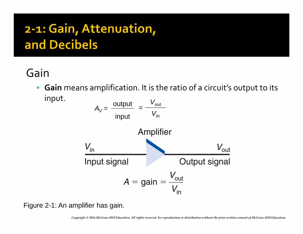
Copyright © 2016 McGraw-Hill Education. All rights reserved. No reproduction or distribution without the prior written consent of McGraw-Hill Education.
Gain Gain means amplification. It is the ratio of a circuit’s output to its
input.
Figure 2-1: An amplifier has gain.
AV = =output
input
Vout
Vin
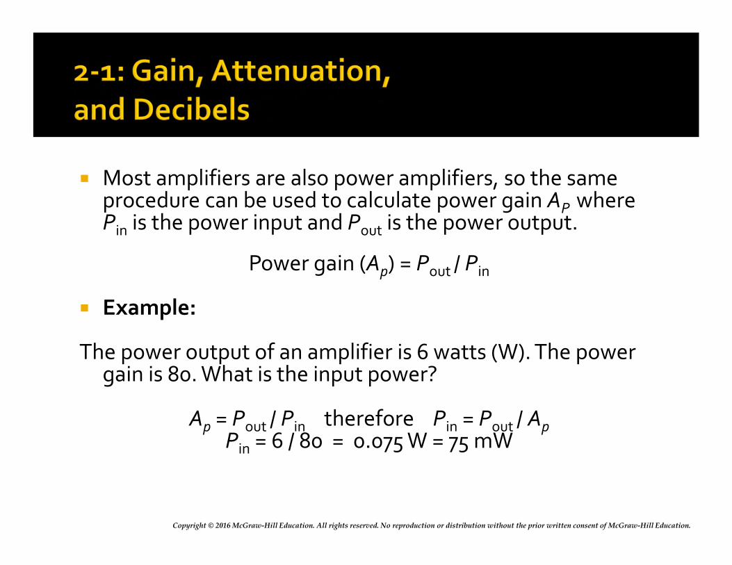
Copyright © 2016 McGraw-Hill Education. All rights reserved. No reproduction or distribution without the prior written consent of McGraw-Hill Education.
Most amplifiers are also power amplifiers, so the same procedure can be used to calculate power gain AP where Pin is the power input and Pout is the power output.
Power gain (Ap) = Pout / Pin
Example:
The power output of an amplifier is 6 watts (W). The power gain is 80. What is the input power?
Ap = Pout / Pin therefore Pin = Pout / ApPin = 6 / 80 = 0.075 W = 75 mW
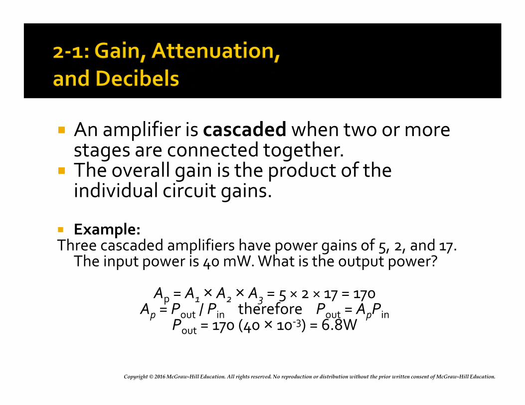
Copyright © 2016 McGraw-Hill Education. All rights reserved. No reproduction or distribution without the prior written consent of McGraw-Hill Education.
An amplifier is cascaded when two or more stages are connected together.
The overall gain is the product of the individual circuit gains.
Example:Three cascaded amplifiers have power gains of 5, 2, and 17.
The input power is 40 mW. What is the output power?
Ap = A1 × A2 × A3 = 5 × 2 × 17 = 170Ap = Pout / Pin therefore Pout = ApPin
Pout = 170 (40 × 10-3) = 6.8W
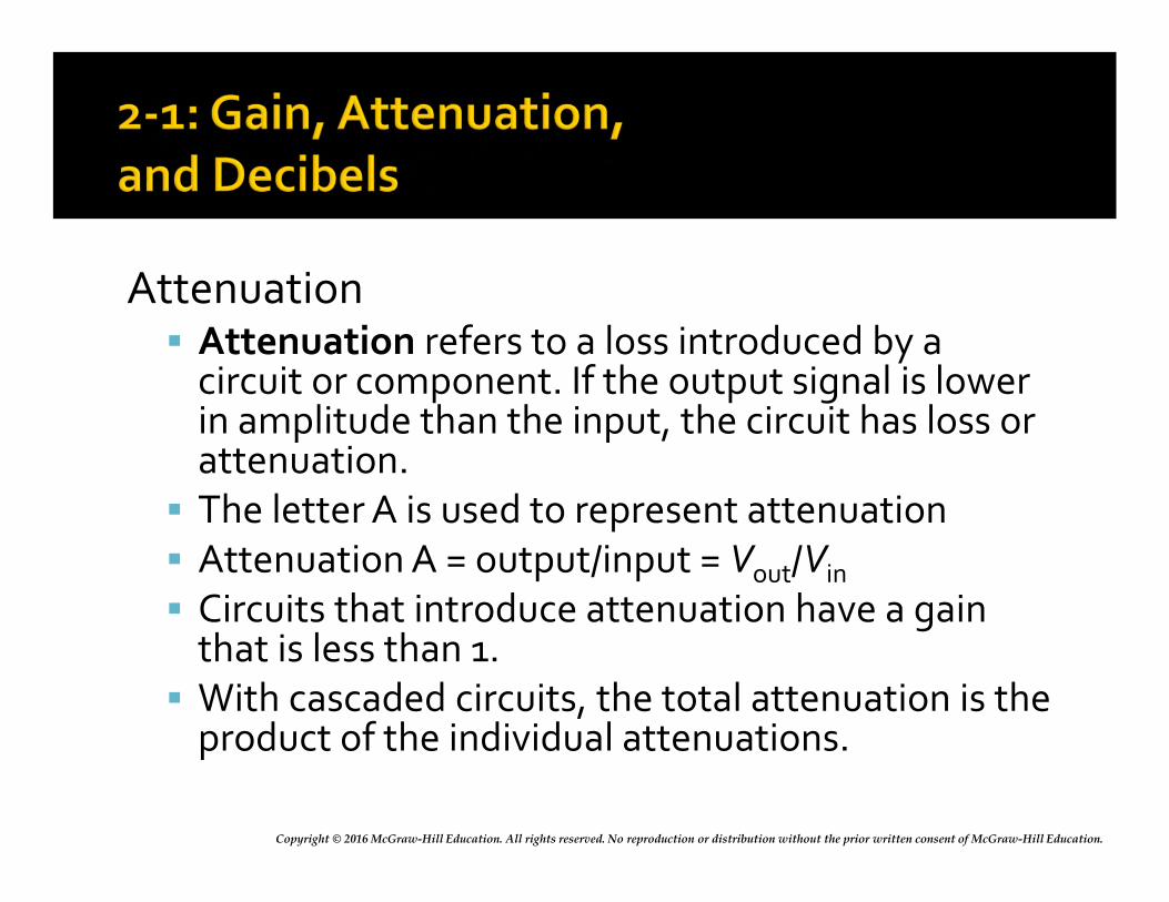
Copyright © 2016 McGraw-Hill Education. All rights reserved. No reproduction or distribution without the prior written consent of McGraw-Hill Education.
Attenuation Attenuation refers to a loss introduced by a
circuit or component. If the output signal is lower in amplitude than the input, the circuit has loss or attenuation. The letter A is used to represent attenuation Attenuation A = output/input = Vout/Vin
Circuits that introduce attenuation have a gain that is less than 1. With cascaded circuits, the total attenuation is the
product of the individual attenuations.
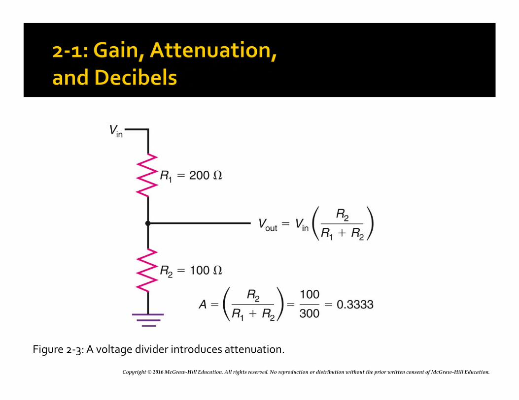
Copyright © 2016 McGraw-Hill Education. All rights reserved. No reproduction or distribution without the prior written consent of McGraw-Hill Education.
Figure 2-3: A voltage divider introduces attenuation.
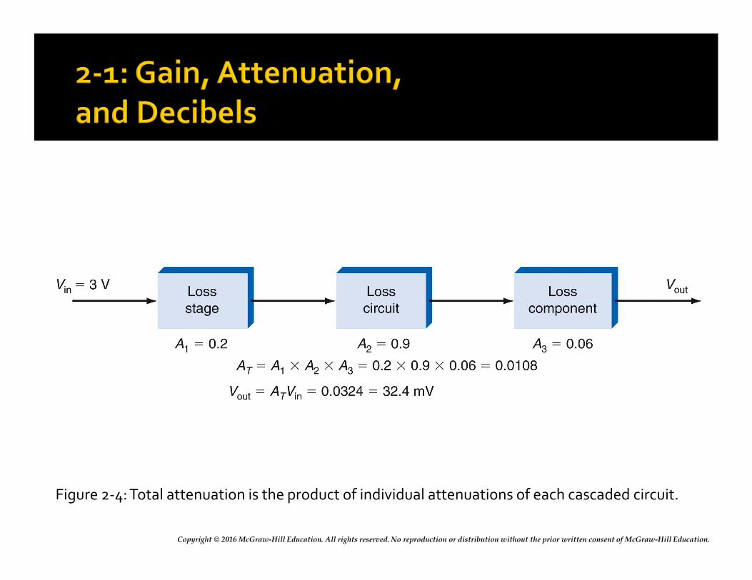
Copyright © 2016 McGraw-Hill Education. All rights reserved. No reproduction or distribution without the prior written consent of McGraw-Hill Education.
Figure 2-4: Total attenuation is the product of individual attenuations of each cascaded circuit.
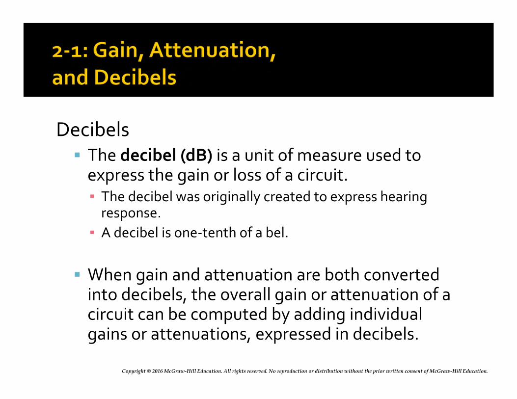
Copyright © 2016 McGraw-Hill Education. All rights reserved. No reproduction or distribution without the prior written consent of McGraw-Hill Education.
Decibels The decibel (dB) is a unit of measure used to
express the gain or loss of a circuit.▪ The decibel was originally created to express hearing
response.
▪ A decibel is one-tenth of a bel.
When gain and attenuation are both converted into decibels, the overall gain or attenuation of a circuit can be computed by adding individual gains or attenuations, expressed in decibels.
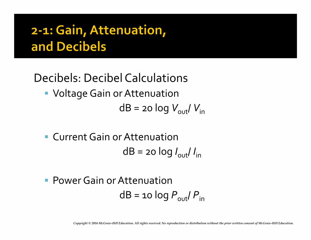
Copyright © 2016 McGraw-Hill Education. All rights reserved. No reproduction or distribution without the prior written consent of McGraw-Hill Education.
Decibels: Decibel Calculations Voltage Gain or Attenuation
dB = 20 log Vout/ Vin
Current Gain or Attenuation
dB = 20 log Iout/ Iin
Power Gain or Attenuation
dB = 10 log Pout/ Pin
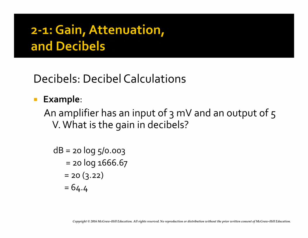
Copyright © 2016 McGraw-Hill Education. All rights reserved. No reproduction or distribution without the prior written consent of McGraw-Hill Education.
Decibels: Decibel Calculations
Example:
An amplifier has an input of 3 mV and an output of 5 V. What is the gain in decibels?
dB = 20 log 5/0.003
= 20 log 1666.67
= 20 (3.22)
= 64.4
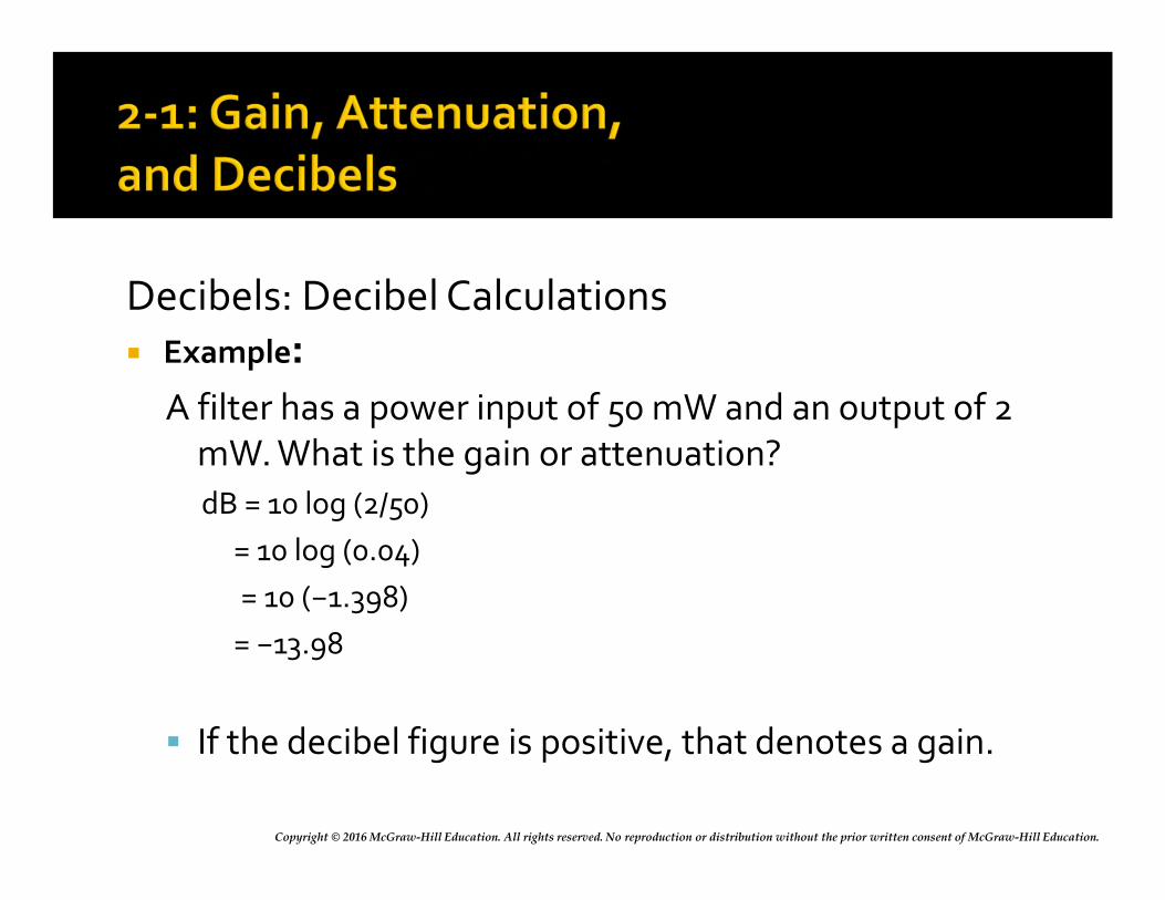
Copyright © 2016 McGraw-Hill Education. All rights reserved. No reproduction or distribution without the prior written consent of McGraw-Hill Education.
Decibels: Decibel Calculations Example:
A filter has a power input of 50 mW and an output of 2 mW. What is the gain or attenuation?
dB = 10 log (2/50)
= 10 log (0.04)
= 10 (−1.398)
= −13.98
If the decibel figure is positive, that denotes a gain.
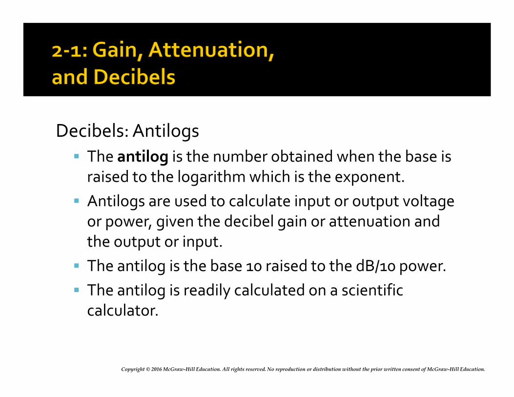
Copyright © 2016 McGraw-Hill Education. All rights reserved. No reproduction or distribution without the prior written consent of McGraw-Hill Education.
Decibels: Antilogs
The antilog is the number obtained when the base is raised to the logarithm which is the exponent.
Antilogs are used to calculate input or output voltage or power, given the decibel gain or attenuation and the output or input.
The antilog is the base 10 raised to the dB/10 power.
The antilog is readily calculated on a scientific calculator.
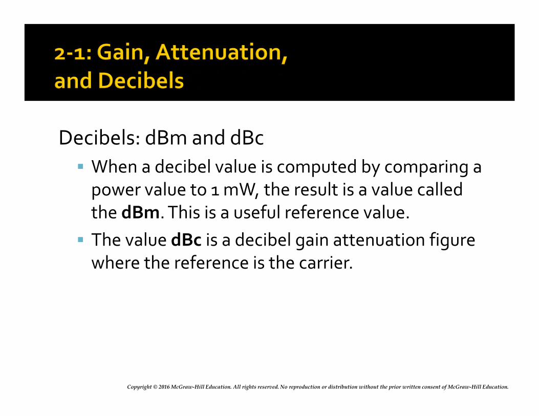
Copyright © 2016 McGraw-Hill Education. All rights reserved. No reproduction or distribution without the prior written consent of McGraw-Hill Education.
Decibels: dBm and dBc
When a decibel value is computed by comparing a power value to 1 mW, the result is a value called the dBm. This is a useful reference value.
The value dBc is a decibel gain attenuation figure where the reference is the carrier.
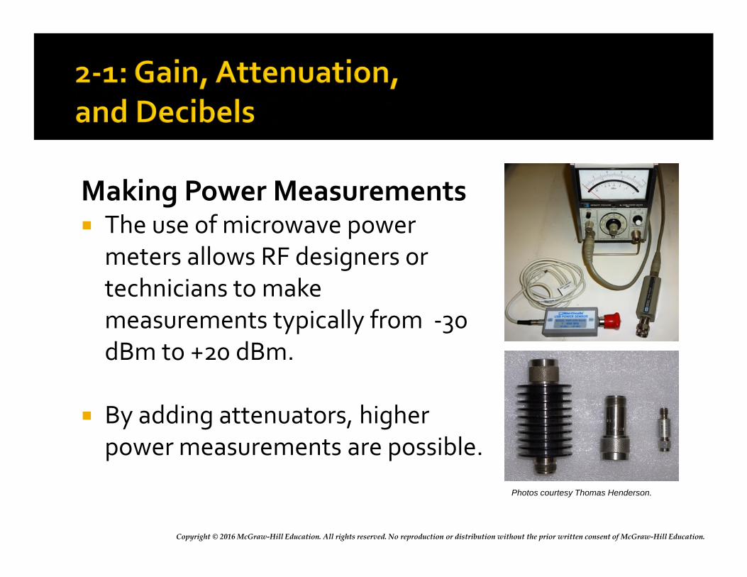
Copyright © 2016 McGraw-Hill Education. All rights reserved. No reproduction or distribution without the prior written consent of McGraw-Hill Education.
Making Power Measurements The use of microwave power
meters allows RF designers or technicians to make measurements typically from -30 dBm to +20 dBm.
By adding attenuators, higher power measurements are possible.
Photos courtesy Thomas Henderson.
Copyright © 2016 McGraw-Hill Education. All rights reserved. No reproduction or distribution without the prior written consent of McGraw-Hill Education.
Virtually all communications equipment contains tuned circuits made up of inductors and capacitors that resonate at specific frequencies.
Copyright © 2016 McGraw-Hill Education. All rights reserved. No reproduction or distribution without the prior written consent of McGraw-Hill Education.
Reactive Components
All tuned circuits and many filters are made up of inductive and capacitive elements.
Opposition to alternating-current flow offered by coils and capacitors is known as reactance.
Reactance is expressed in ohms (Ω).
Copyright © 2016 McGraw-Hill Education. All rights reserved. No reproduction or distribution without the prior written consent of McGraw-Hill Education.
Reactive Components: Capacitors A capacitor used in an ac circuit charges and
discharges.
Capacitors tend to oppose voltage changes across them.
Opposition to alternating current offered by a capacitor is known as capacitive reactance (Xc).
Capacitive reactance (Xc) is inversely proportional to the value of capacitance (C) and operating frequency (f).
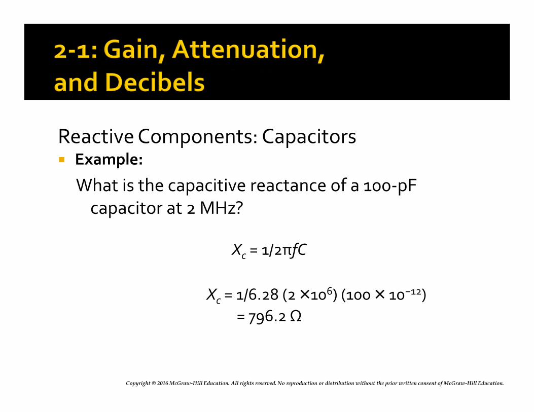
Copyright © 2016 McGraw-Hill Education. All rights reserved. No reproduction or distribution without the prior written consent of McGraw-Hill Education.
Reactive Components: Capacitors Example:
What is the capacitive reactance of a 100-pF capacitor at 2 MHz?
Xc = 1/2πfC
Xc = 1/6.28 (2 ×10⁶) (100 × 10−12)
= 796.2 Ω
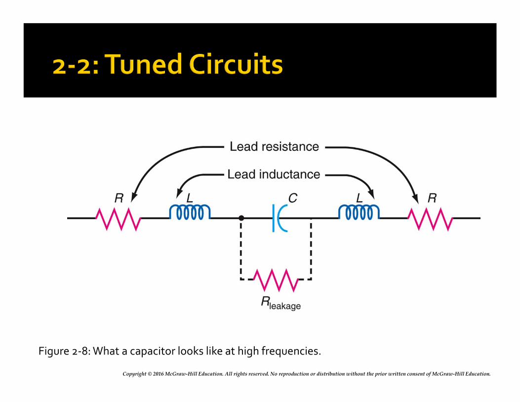
Copyright © 2016 McGraw-Hill Education. All rights reserved. No reproduction or distribution without the prior written consent of McGraw-Hill Education.
Figure 2-8: What a capacitor looks like at high frequencies.
Copyright © 2016 McGraw-Hill Education. All rights reserved. No reproduction or distribution without the prior written consent of McGraw-Hill Education.
Reactive Components: Inductors An inductor, also called a coil or choke, is a winding of
multiple turns of wire.
When a current is passed through a coil, a magnetic field is produced around the coil.
If the applied voltage and current are varying, this causes a voltage to be self-induced into the coil winding.
This process has the effect of opposing current changes in the coil. This effect is known as inductance.
Copyright © 2016 McGraw-Hill Education. All rights reserved. No reproduction or distribution without the prior written consent of McGraw-Hill Education.
Reactive Components: Inductors
The basic unit of inductance is the henry (H). However, practical inductance values are in the millihenry (mH = 10-3), microhenry (μH = 10-6), and nanohenry (nH = 10−9 H) regions.
Opposition to alternating current offered by inductors is continuous and constant and is known as inductive reactance (XL).
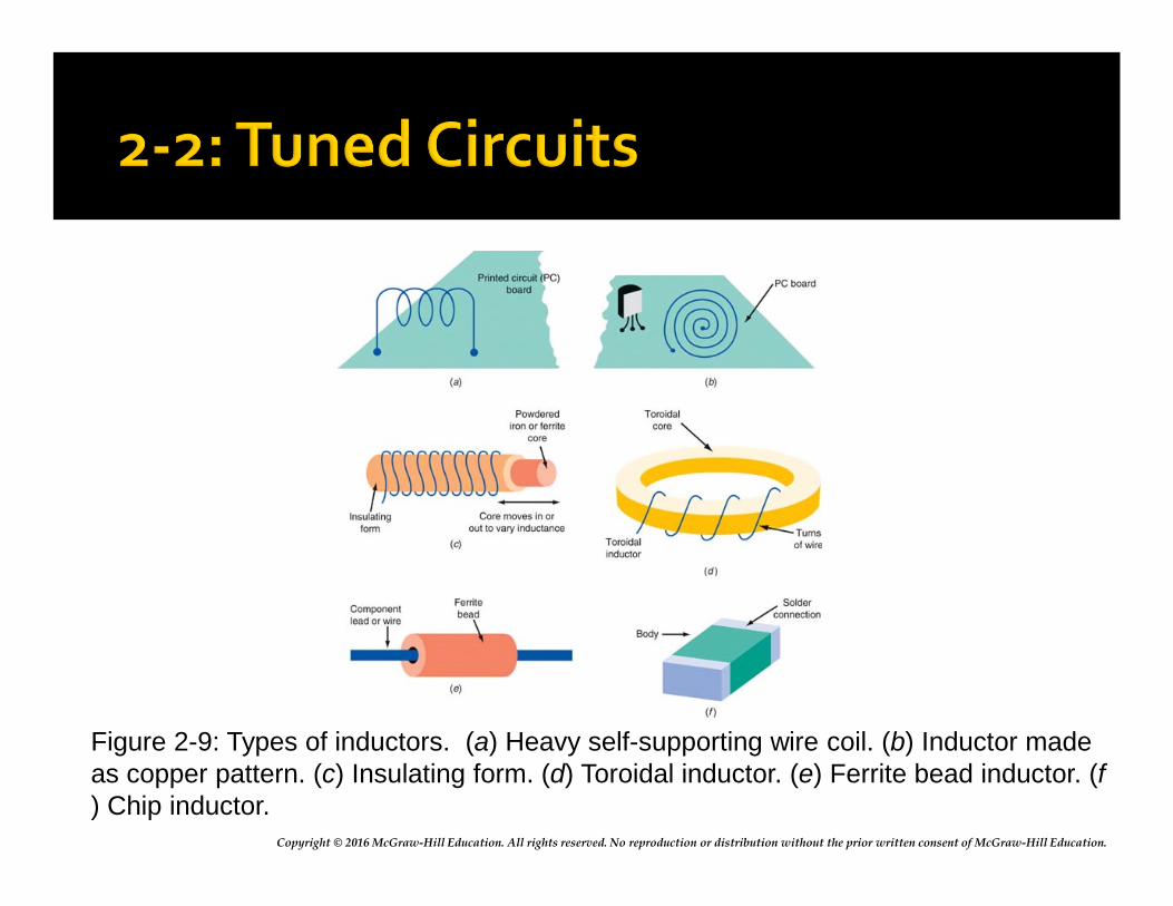
Copyright © 2016 McGraw-Hill Education. All rights reserved. No reproduction or distribution without the prior written consent of McGraw-Hill Education.
Figure 2-9: Types of inductors. (a) Heavy self-supporting wire coil. (b) Inductor made as copper pattern. (c) Insulating form. (d) Toroidal inductor. (e) Ferrite bead inductor. (f ) Chip inductor.
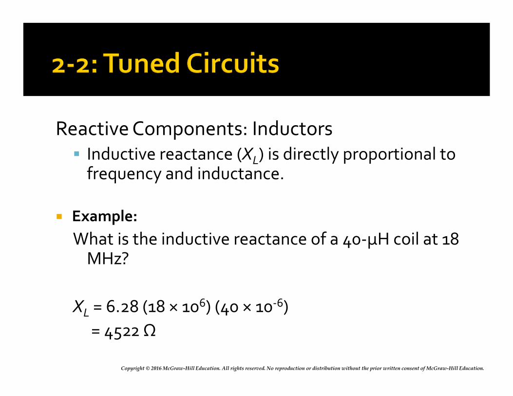
Copyright © 2016 McGraw-Hill Education. All rights reserved. No reproduction or distribution without the prior written consent of McGraw-Hill Education.
Reactive Components: Inductors Inductive reactance (XL) is directly proportional to
frequency and inductance.
Example:
What is the inductive reactance of a 40-μH coil at 18 MHz?
XL = 6.28 (18 × 106) (40 × 10-6)
= 4522 Ω
Copyright © 2016 McGraw-Hill Education. All rights reserved. No reproduction or distribution without the prior written consent of McGraw-Hill Education.
Reactive Components: Resistors At low frequencies, a standard resistor offers
nearly pure resistance.
At high frequencies, a resistor’s leads have inductance.
A resistor’s lead inductance and stray capacitance cause the resistor to act like a complex RLC circuit.
Tiny resistor chips used in surface mount circuits minimize inductance and stray capacitance.
Film resistors minimize thermal effect noise.
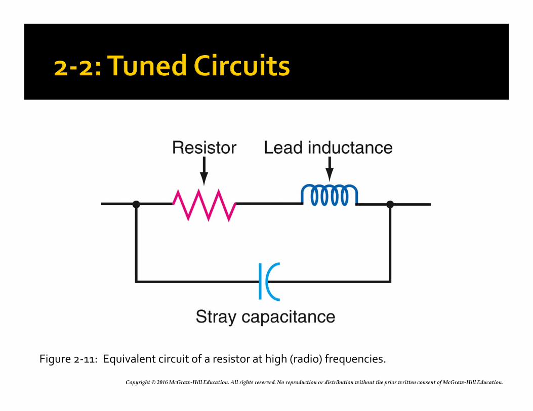
Copyright © 2016 McGraw-Hill Education. All rights reserved. No reproduction or distribution without the prior written consent of McGraw-Hill Education.
Figure 2-11: Equivalent circuit of a resistor at high (radio) frequencies.
Copyright © 2016 McGraw-Hill Education. All rights reserved. No reproduction or distribution without the prior written consent of McGraw-Hill Education.
Reactive Components: Skin Effect.
Skin effect is the tendency of electrons flowing in a conductor to flow near and on the outer surface of the conductor frequencies in the VHF, UHF, and microwave regions.
This process increases the resistance of the conductor and greatly affects the performance of the circuit.
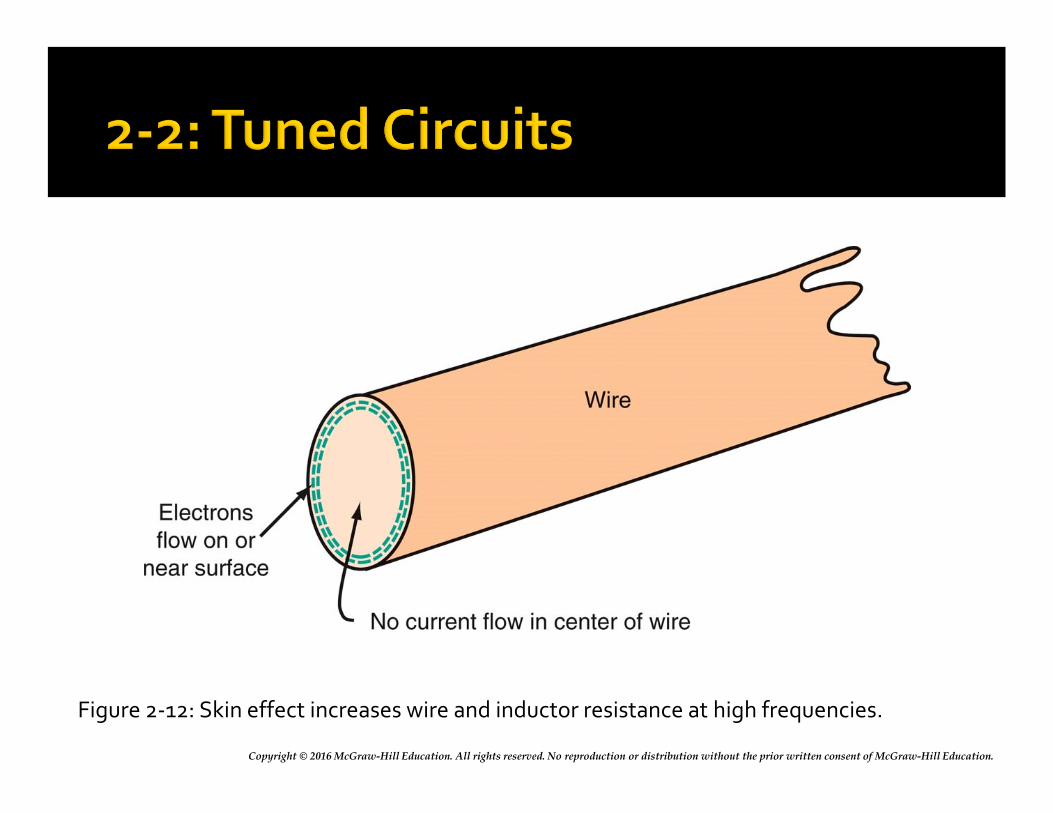
Copyright © 2016 McGraw-Hill Education. All rights reserved. No reproduction or distribution without the prior written consent of McGraw-Hill Education.
Figure 2-12: Skin effect increases wire and inductor resistance at high frequencies.
Copyright © 2016 McGraw-Hill Education. All rights reserved. No reproduction or distribution without the prior written consent of McGraw-Hill Education.
Tuned Circuits and Resonance
A tuned circuit is made up of inductance and capacitance and resonates at a specific frequency, the resonant frequency.
The terms tuned circuit and resonant circuit are used interchangeably.
Tuned circuits are frequency-selective and respond best at their resonant frequency.
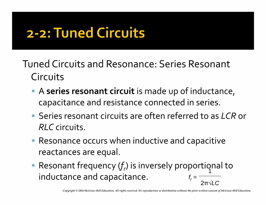
Copyright © 2016 McGraw-Hill Education. All rights reserved. No reproduction or distribution without the prior written consent of McGraw-Hill Education.
Tuned Circuits and Resonance: Series Resonant Circuits
A series resonant circuit is made up of inductance, capacitance and resistance connected in series.
Series resonant circuits are often referred to as LCR or RLC circuits.
Resonance occurs when inductive and capacitive reactances are equal.
Resonant frequency (fr) is inversely proportional to inductance and capacitance. fr =
1
2π√LC
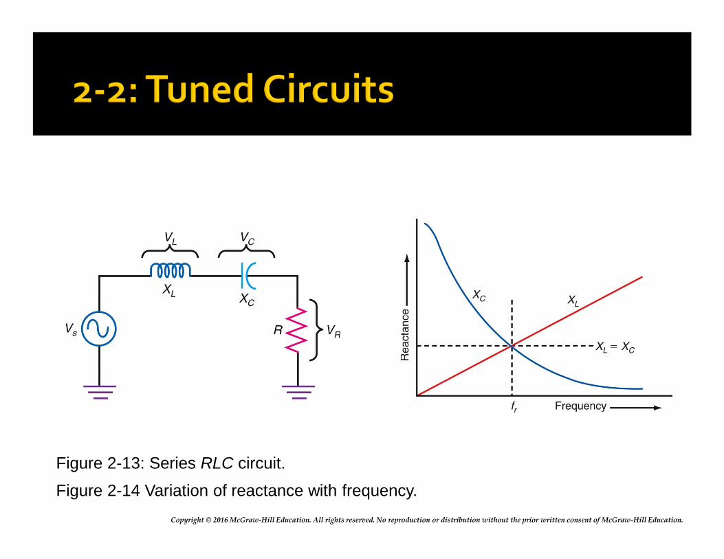
Copyright © 2016 McGraw-Hill Education. All rights reserved. No reproduction or distribution without the prior written consent of McGraw-Hill Education.
Figure 2-13: Series RLC circuit.
Figure 2-14 Variation of reactance with frequency.
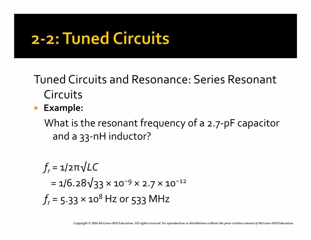
Copyright © 2016 McGraw-Hill Education. All rights reserved. No reproduction or distribution without the prior written consent of McGraw-Hill Education.
Tuned Circuits and Resonance: Series Resonant Circuits
Example:
What is the resonant frequency of a 2.7-pF capacitor and a 33-nH inductor?
fr = 1/2π√LC
= 1/6.28√33 × 10−9 × 2.7 × 10−12
fr = 5.33 × 10⁸ Hz or 533 MHz
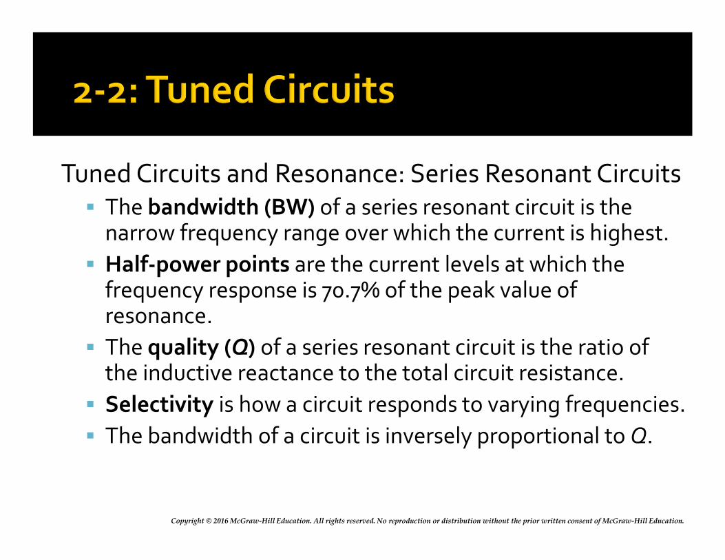
Copyright © 2016 McGraw-Hill Education. All rights reserved. No reproduction or distribution without the prior written consent of McGraw-Hill Education.
Tuned Circuits and Resonance: Series Resonant Circuits The bandwidth (BW) of a series resonant circuit is the
narrow frequency range over which the current is highest.
Half-power points are the current levels at which the frequency response is 70.7% of the peak value of resonance.
The quality (Q) of a series resonant circuit is the ratio of the inductive reactance to the total circuit resistance.
Selectivity is how a circuit responds to varying frequencies.
The bandwidth of a circuit is inversely proportional to Q.
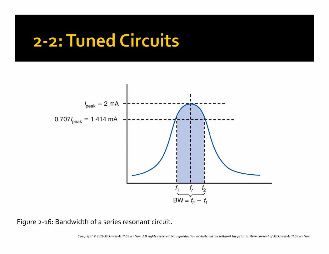
Copyright © 2016 McGraw-Hill Education. All rights reserved. No reproduction or distribution without the prior written consent of McGraw-Hill Education.
Figure 2-16: Bandwidth of a series resonant circuit.
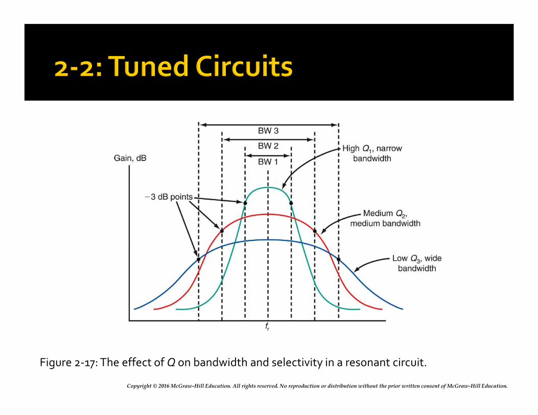
Copyright © 2016 McGraw-Hill Education. All rights reserved. No reproduction or distribution without the prior written consent of McGraw-Hill Education.
Figure 2-17: The effect of Q on bandwidth and selectivity in a resonant circuit.
Copyright © 2016 McGraw-Hill Education. All rights reserved. No reproduction or distribution without the prior written consent of McGraw-Hill Education.
Tuned Circuits and Resonance: Parallel Resonant Circuits A parallel resonant circuit is formed when the
inductor and capacitor of a tuned circuit are connected in parallel with the applied voltage.
A parallel resonant circuit is often referred to as a LCRor RLC circuit.
Resonance occurs when inductive and capacitive reactances are equal.
The resonant frequency (fr) is inversely proportional to inductance and capacitance.
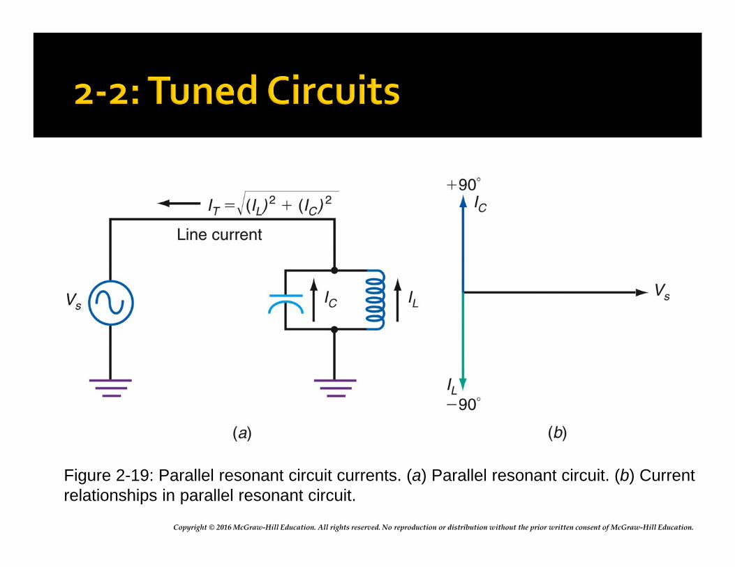
Copyright © 2016 McGraw-Hill Education. All rights reserved. No reproduction or distribution without the prior written consent of McGraw-Hill Education.
Figure 2-19: Parallel resonant circuit currents. (a) Parallel resonant circuit. (b) Currentrelationships in parallel resonant circuit.
Copyright © 2016 McGraw-Hill Education. All rights reserved. No reproduction or distribution without the prior written consent of McGraw-Hill Education.
Tuned Circuits and Resonance: Parallel Resonant Circuits At resonance, a parallel tuned circuit appears to ▪ have infinite resistance
▪ draw no current from the source
▪ have infinite impedance
▪ act as an open circuit.
However, there is a high circulating current between the inductor and capacitor, storing and transferring energy between them.
Copyright © 2016 McGraw-Hill Education. All rights reserved. No reproduction or distribution without the prior written consent of McGraw-Hill Education.
Tuned Circuits and Resonance: Parallel Resonant Circuit
Because such a circuit acts as a kind of storage vessel for electric energy, it is often referred to as a tank circuit and the circulating current is referred to as the tank current.
Copyright © 2016 McGraw-Hill Education. All rights reserved. No reproduction or distribution without the prior written consent of McGraw-Hill Education.
A filter is a frequency-selective circuit. Filters pass certain frequencies and reject
others. Passive filters are created using components
such as: resistors, capacitors, and inductors that do not amplify.
Active filters use amplifying devices such as transistors and operational amplifiers.
Copyright © 2016 McGraw-Hill Education. All rights reserved. No reproduction or distribution without the prior written consent of McGraw-Hill Education.
There are five basic kinds of filter circuits: Low-pass filters only pass frequencies below a critical
(cutoff) frequency. High-pass filters only pass frequencies above the
cutoff frequency. Bandpass filters pass frequencies over a narrow
range between lower and upper cutoff frequencies. Band-reject filters reject or stop frequencies over a
narrow range between lower and upper cutoff frequencies.
All-pass filters pass all frequencies over a desired range but have a predictable phase shift characteristic.
Copyright © 2016 McGraw-Hill Education. All rights reserved. No reproduction or distribution without the prior written consent of McGraw-Hill Education.
RC Filters
RC filters use combinations of resistors and capacitors to achieve a desired frequency response.
Most RC filters are of the low-pass or high-pass type.
Any low-pass or high-pass filter is effectively a frequency-dependent voltage divider.
An RC coupling circuit is a high-pass filter because the ac input component is developed across the resistor while dc voltage is blocked by a capacitor.
Copyright © 2016 McGraw-Hill Education. All rights reserved. No reproduction or distribution without the prior written consent of McGraw-Hill Education.
RC Filters: Low-Pass Filter A low-pass filter is a circuit that introduces no
attenuation at frequencies below the cutoff frequency but completely eliminates all signals with frequencies above the cutoff.
Low-pass filters are sometimes referred to as high cut filters.
The cutoff frequency of a filter is that point where the resistance (R) and capacitive reactance (XC) are equal.
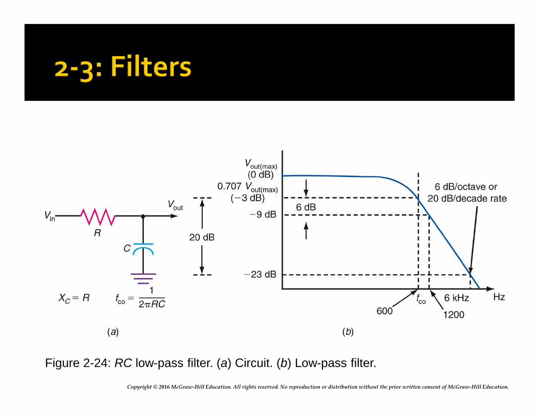
Copyright © 2016 McGraw-Hill Education. All rights reserved. No reproduction or distribution without the prior written consent of McGraw-Hill Education.
Figure 2-24: RC low-pass filter. (a) Circuit. (b) Low-pass filter.
Copyright © 2016 McGraw-Hill Education. All rights reserved. No reproduction or distribution without the prior written consent of McGraw-Hill Education.
RC Filters: High-Pass Filter
A high-pass filter passes frequencies above the cutoff frequency with little or no attenuation but greatly attenuates those signals below the cutoff.
The basic high-pass filter is a voltage divider with the capacitor serving as the frequency-sensitive component.
A high-pass filter can be implemented with a coil and a resistor.
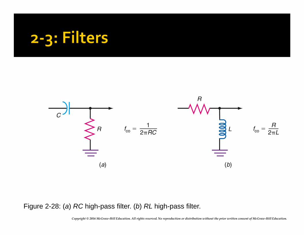
Copyright © 2016 McGraw-Hill Education. All rights reserved. No reproduction or distribution without the prior written consent of McGraw-Hill Education.
Figure 2-28: (a) RC high-pass filter. (b) RL high-pass filter.
Copyright © 2016 McGraw-Hill Education. All rights reserved. No reproduction or distribution without the prior written consent of McGraw-Hill Education.
RC Filters: RC Notch Filter Notch filters, also called bandstop or band-reject
filters, attenuate a narrow range of frequencies around a center point (frequency).
A simple notch filter implemented with resistors and capacitors is called a parallel-T or twin-T filter.
The center notch frequency is calculated:
fnotch = 1
2πRC
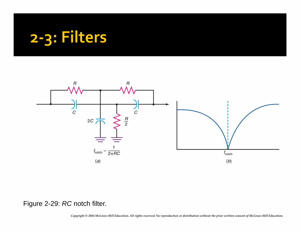
Copyright © 2016 McGraw-Hill Education. All rights reserved. No reproduction or distribution without the prior written consent of McGraw-Hill Education.
Figure 2-29: RC notch filter.
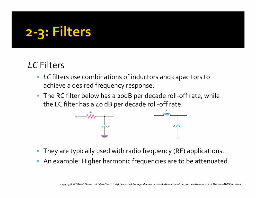
Copyright © 2016 McGraw-Hill Education. All rights reserved. No reproduction or distribution without the prior written consent of McGraw-Hill Education.
LC Filters LC filters use combinations of inductors and capacitors to
achieve a desired frequency response.
The RC filter below has a 20dB per decade roll-off rate, while the LC filter has a 40 dB per decade roll-off rate.
They are typically used with radio frequency (RF) applications.
An example: Higher harmonic frequencies are to be attenuated.
Copyright © 2016 McGraw-Hill Education. All rights reserved. No reproduction or distribution without the prior written consent of McGraw-Hill Education.
LC Filters
Passband is the frequency range over which the filter passes signals.
Stop band is the range of frequencies outside the passband; that is, the range of frequencies that is greatly attenuated by the filter.
Attenuation is the amount by which undesired frequencies in the stop band are reduced.
Copyright © 2016 McGraw-Hill Education. All rights reserved. No reproduction or distribution without the prior written consent of McGraw-Hill Education.
LC Filters
Insertion loss is the loss the filter introduces to the signals in the passband.
Impedance is the resistive value of the load and source terminations of the filter.
Ripple is a term used to describe the amplitude variation with frequency in the passband.
Shape factor is the ratio of the stop bandwidth to the pass bandwidth of a bandpass filter.
Copyright © 2016 McGraw-Hill Education. All rights reserved. No reproduction or distribution without the prior written consent of McGraw-Hill Education.
LC Filters A pole is a frequency at which there is a high
impedance in the circuit.
Zero is a term used to refer to a frequency at which there is zero impedance in the circuit.
Envelope delay or time delay is the time it takes for a specific point on an input waveform to pass through the filter.
Roll-off or attenuation rate is the rate of change of amplitude with frequency in a filter.
Copyright © 2016 McGraw-Hill Education. All rights reserved. No reproduction or distribution without the prior written consent of McGraw-Hill Education.
Types of Filters
The most widely used LC filters are named after the people who discovered them and developed the analysis and design method for each.
▪ Butterworth: The Butterworth filter effect has maximum flatness in response in the passband and a uniform attenuation with frequency.
▪ Chebyshev: Has extremely good selectivity, and attenuation just outside the passband is very high, but has ripple in the passband.
Copyright © 2016 McGraw-Hill Education. All rights reserved. No reproduction or distribution without the prior written consent of McGraw-Hill Education.
Types of Filters ▪ Cauer (Elliptical): Produces greater attenuation out of
the passband, but with higher ripple within and outside of the passband.
▪ Bessel (Thomson): Provides the desired frequency response (i.e., low-pass, bandpass, etc.) but has a constant time delay in the passband.
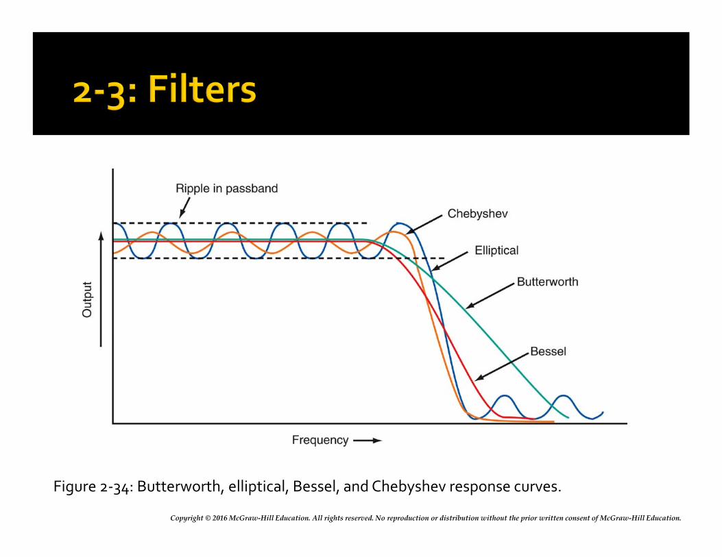
Copyright © 2016 McGraw-Hill Education. All rights reserved. No reproduction or distribution without the prior written consent of McGraw-Hill Education.
Figure 2-34: Butterworth, elliptical, Bessel, and Chebyshev response curves.
Copyright © 2016 McGraw-Hill Education. All rights reserved. No reproduction or distribution without the prior written consent of McGraw-Hill Education.
Types of Filters: Mechanical and Bandpass Filters
A mechanical filter uses resonant vibrations of mechanical disks to provide the selectivity.
Bandpass filters, configured with series or parallel resonant circuits, allow a narrow range of frequencies around a center frequency to pass with minimum attenuation but rejects frequencies above and below this range.
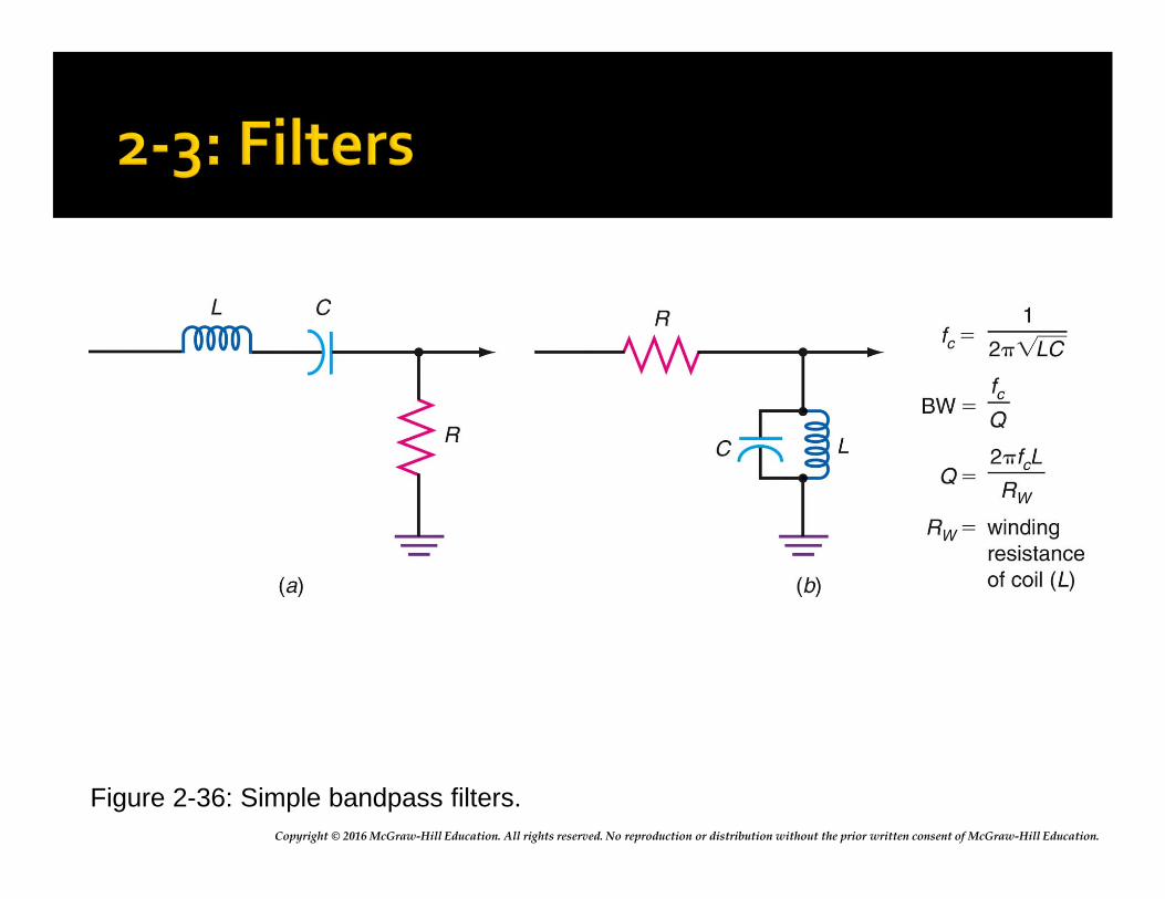
Copyright © 2016 McGraw-Hill Education. All rights reserved. No reproduction or distribution without the prior written consent of McGraw-Hill Education.
Figure 2-36: Simple bandpass filters.
Copyright © 2016 McGraw-Hill Education. All rights reserved. No reproduction or distribution without the prior written consent of McGraw-Hill Education.
Types of Filters: Band-Reject Filters
Band-reject filters reject a narrow band of frequencies around a center or notch frequency.
Band-reject filters are also known as bandstop filters or traps.
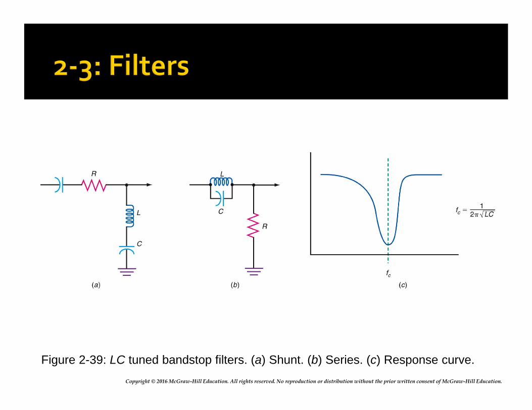
Copyright © 2016 McGraw-Hill Education. All rights reserved. No reproduction or distribution without the prior written consent of McGraw-Hill Education.
Figure 2-39: LC tuned bandstop filters. (a) Shunt. (b) Series. (c) Response curve.
Copyright © 2016 McGraw-Hill Education. All rights reserved. No reproduction or distribution without the prior written consent of McGraw-Hill Education.
Active Filters Active filters are frequency-selective circuits that
incorporate RC networks and amplifiers with feedback to produce low-pass, high-pass, bandpass, and bandstop performance. Advantages are:▪ Gain
▪ No inductors
▪ Easy to tune
▪ Isolation
▪ Easier impedance matching
Copyright © 2016 McGraw-Hill Education. All rights reserved. No reproduction or distribution without the prior written consent of McGraw-Hill Education.
Active Filters
A special form of active filter is the variable-state filter, which can simultaneously provide low-pass, high-pass, and bandpass operation from one circuit.
Copyright © 2016 McGraw-Hill Education. All rights reserved. No reproduction or distribution without the prior written consent of McGraw-Hill Education.
Crystal and Ceramic Filters Crystal and ceramic filters are made of thin
slivers of quartz crystal or certain other types of ceramic materials.
Crystals and ceramic elements are widely used in oscillators to set frequency of operation to a precise value.
Crystals and ceramic elements are also used as circuit elements to form filters, specifically bandpass filters.
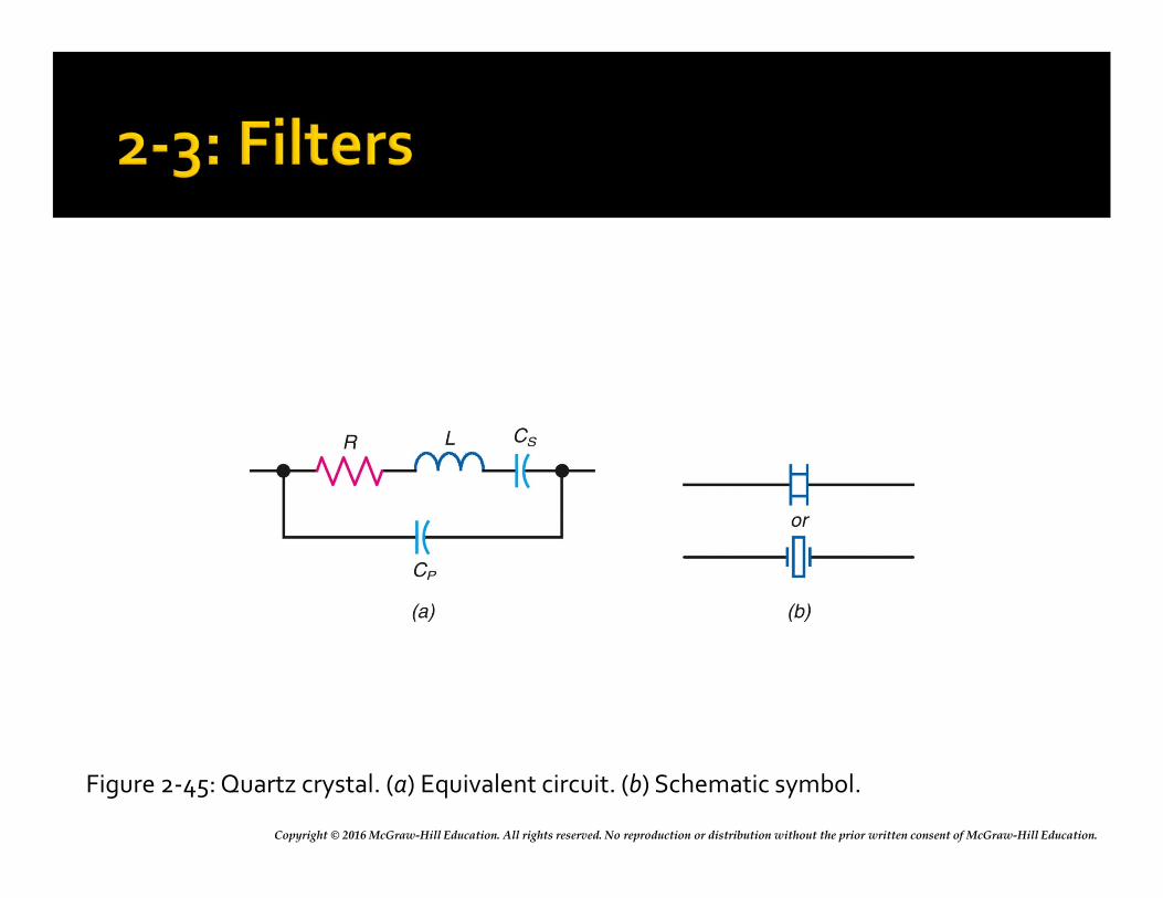
Copyright © 2016 McGraw-Hill Education. All rights reserved. No reproduction or distribution without the prior written consent of McGraw-Hill Education.
Figure 2-45: Quartz crystal. (a) Equivalent circuit. (b) Schematic symbol.
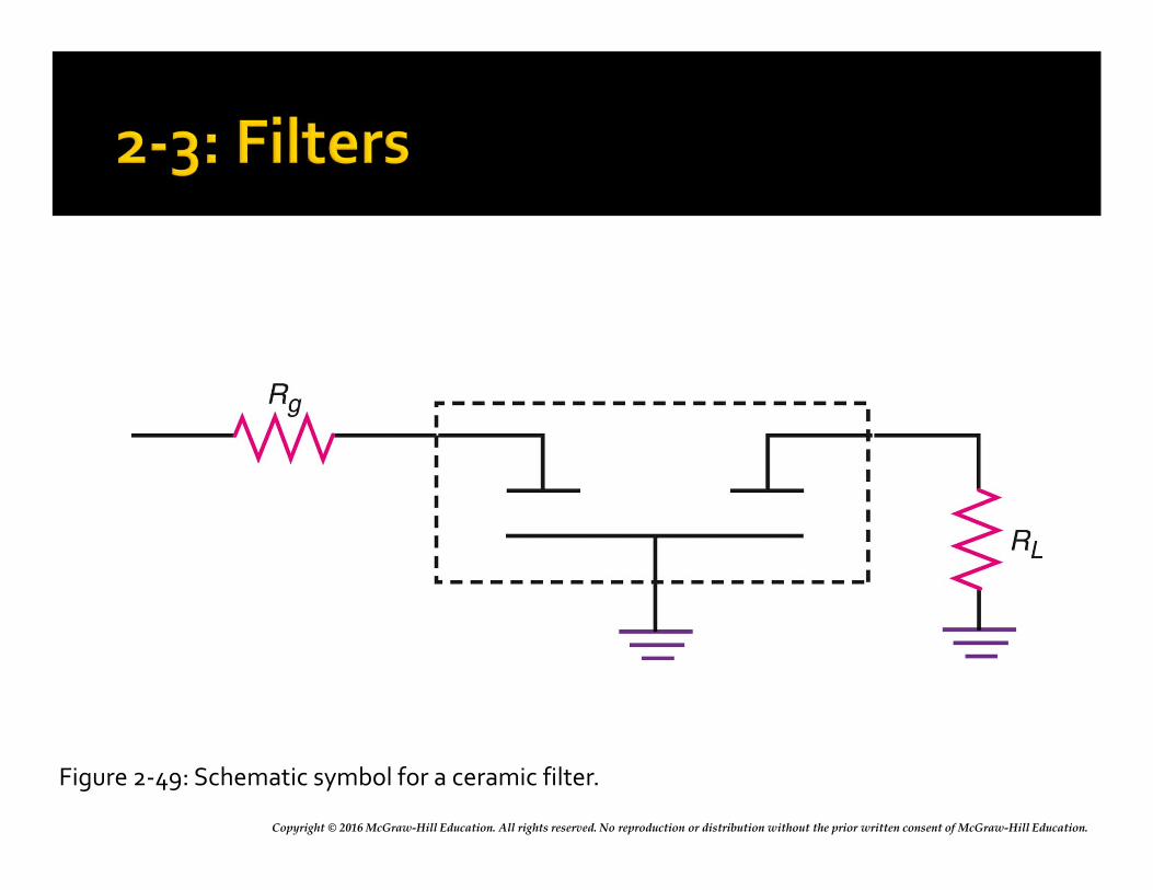
Copyright © 2016 McGraw-Hill Education. All rights reserved. No reproduction or distribution without the prior written consent of McGraw-Hill Education.
Figure 2-49: Schematic symbol for a ceramic filter.
Copyright © 2016 McGraw-Hill Education. All rights reserved. No reproduction or distribution without the prior written consent of McGraw-Hill Education.
Crystal and Ceramic Filters: Surface Acoustic Wave Filters The surface acoustic wave (SAW) filter is a
special form of a crystal filter designed to provide the exact selectivity required by a given application.
SAW filters are normally used at very high radio frequencies where selectivity is difficult to obtain.
They are widely used in modern TV receivers, radar receivers, wireless LANs, and cell phones.
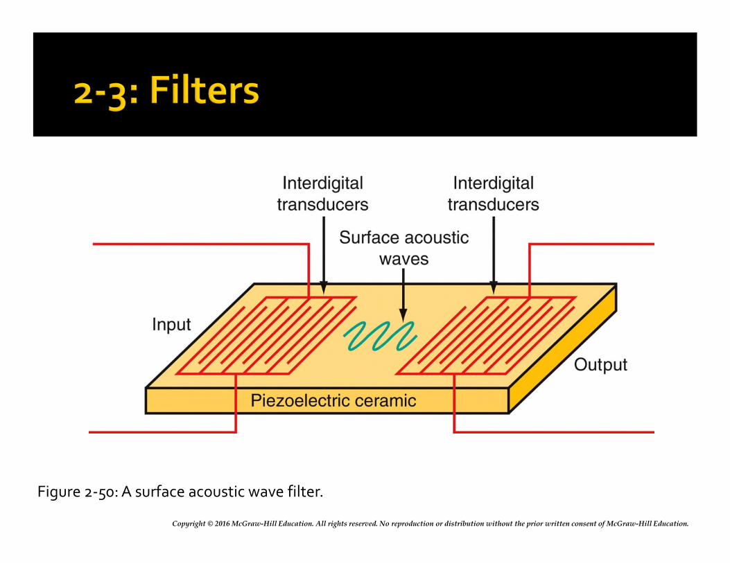
Copyright © 2016 McGraw-Hill Education. All rights reserved. No reproduction or distribution without the prior written consent of McGraw-Hill Education.
Figure 2-50: A surface acoustic wave filter.
Copyright © 2016 McGraw-Hill Education. All rights reserved. No reproduction or distribution without the prior written consent of McGraw-Hill Education.
Switched Capacitor Filters
Switched capacitor filters (SCFs), also known as analog sampled data filters or commutating filters, are active IC filters made of op amps, capacitors, and transistor switches.
They provide a way to make tuned or selective circuits in an IC without the use of discrete inductors, capacitors, or resistors.
The secret to the SCF is that all resistors are replaced by capacitors that are switched by MOSFET switches.
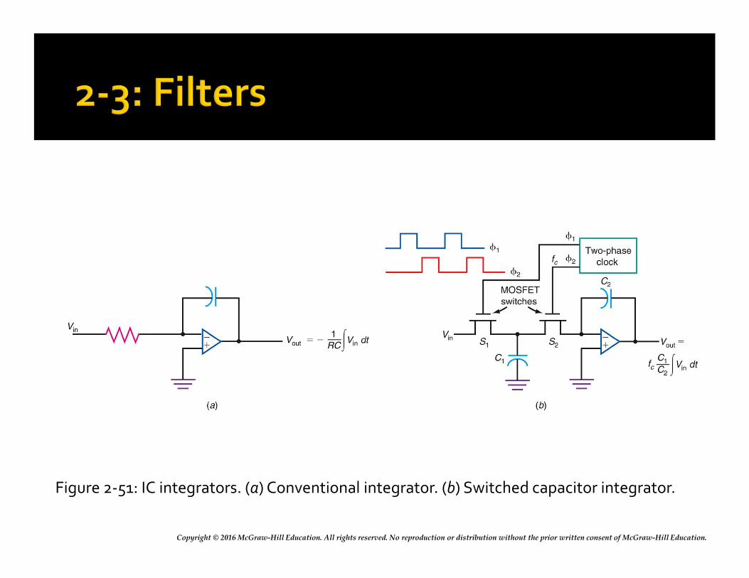
Copyright © 2016 McGraw-Hill Education. All rights reserved. No reproduction or distribution without the prior written consent of McGraw-Hill Education.
Figure 2-51: IC integrators. (a) Conventional integrator. (b) Switched capacitor integrator.
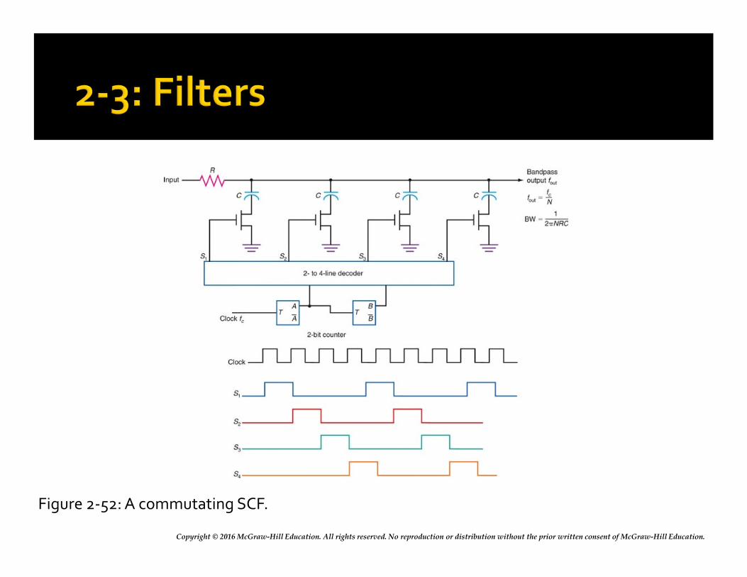
Copyright © 2016 McGraw-Hill Education. All rights reserved. No reproduction or distribution without the prior written consent of McGraw-Hill Education.
Figure 2-52: A commutating SCF.
Copyright © 2016 McGraw-Hill Education. All rights reserved. No reproduction or distribution without the prior written consent of McGraw-Hill Education.
One method used to determine the characteristics and performance of a communication circuit or system, specifically for non-sine wave approach, is Fourier analysis.
The Fourier theory states that a nonsinusoidal waveform can be broken down into individual harmonically related sine wave or cosine wave components.
A square wave is one classic example of this phenomenon.
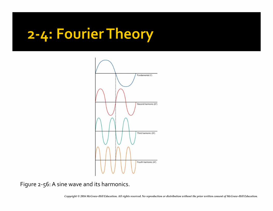
Copyright © 2016 McGraw-Hill Education. All rights reserved. No reproduction or distribution without the prior written consent of McGraw-Hill Education.
Figure 2-56: A sine wave and its harmonics.
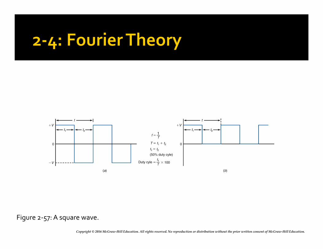
Copyright © 2016 McGraw-Hill Education. All rights reserved. No reproduction or distribution without the prior written consent of McGraw-Hill Education.
Figure 2-57: A square wave.
Copyright © 2016 McGraw-Hill Education. All rights reserved. No reproduction or distribution without the prior written consent of McGraw-Hill Education.
Basic Concepts
Fourier analysis states that a square wave is made up of a sine wave at the fundamental frequency of the square wave plus an infinite number of odd harmonics.
Fourier analysis allows us to determine not only sine-wave components in a complex signal but also a signal’s bandwidth.
Copyright © 2016 McGraw-Hill Education. All rights reserved. No reproduction or distribution without the prior written consent of McGraw-Hill Education.
Time Domain Versus Frequency Domain
Analysis of variations of voltage, current, or power with respect to time are expressed in the time domain.
A frequency domain plots amplitude variations with respect to frequency.
Fourier theory gives us a new and different way to express and illustrate complex signals, that is, with respect to frequency.
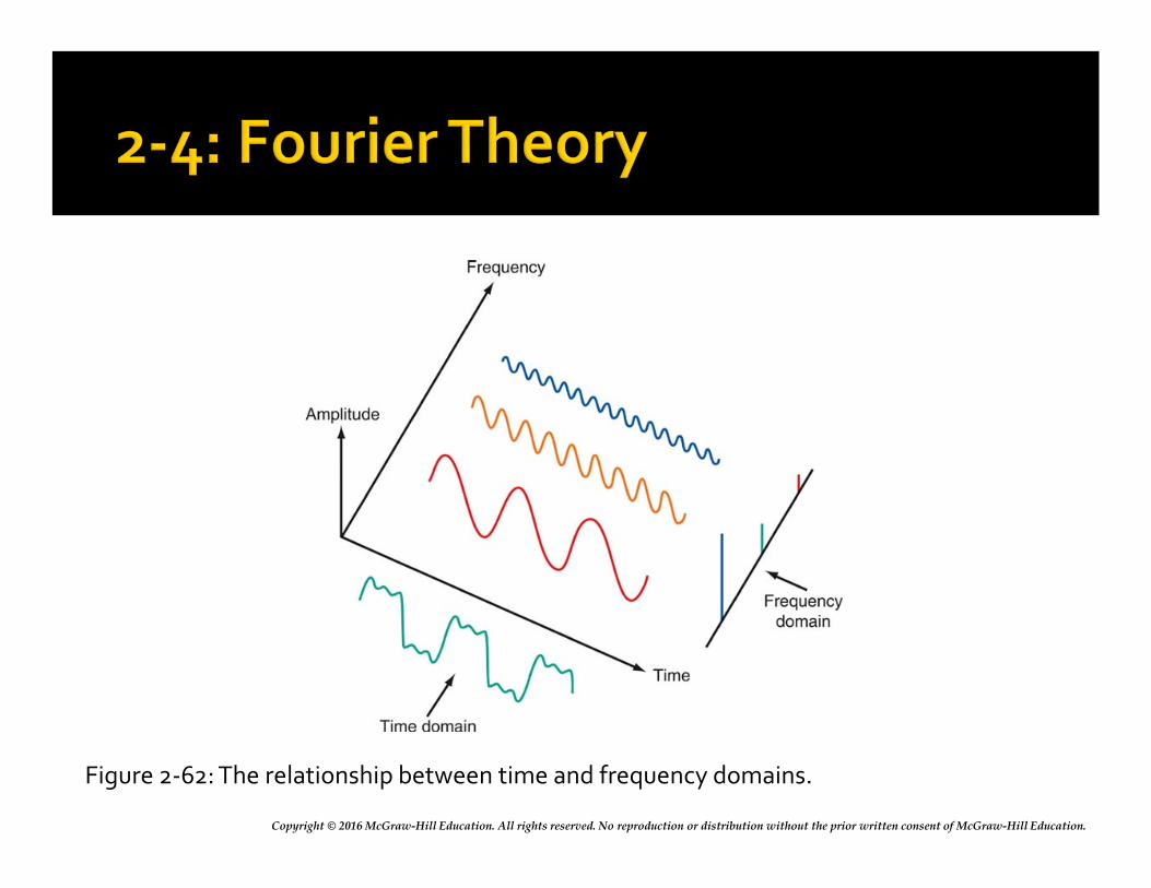
Copyright © 2016 McGraw-Hill Education. All rights reserved. No reproduction or distribution without the prior written consent of McGraw-Hill Education.
Figure 2-62: The relationship between time and frequency domains.
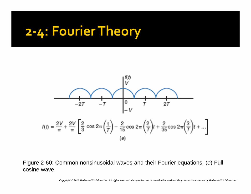
Copyright © 2016 McGraw-Hill Education. All rights reserved. No reproduction or distribution without the prior written consent of McGraw-Hill Education.
Figure 2-60: Common nonsinusoidal waves and their Fourier equations. (e) Full cosine wave.
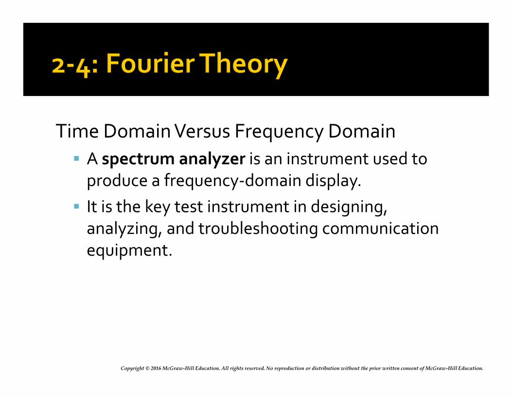
Copyright © 2016 McGraw-Hill Education. All rights reserved. No reproduction or distribution without the prior written consent of McGraw-Hill Education.
Time Domain Versus Frequency Domain
A spectrum analyzer is an instrument used to produce a frequency-domain display.
It is the key test instrument in designing, analyzing, and troubleshooting communication equipment.


![arXiv:2005.13949v1 [physics.app-ph] 25 May 20207.5 MHz F4 6.5 MHz F5 F6 7.5 MHz F7 F8 6.5 MHz F14 9.5 MHz F15 NA F16 8.5 MHz F17 NA F18 NA F19 7.5 MHz F11 6.5 MHz F20 NA F21 8.5 MHz](https://img.pdfslide.us/doc/110x75/5f758878eb2d114487007824/arxiv200513949v1-25-may-2020-75-mhz-f4-65-mhz-f5-f6-75-mhz-f7-f8-65-mhz.jpg)