Embed Size (px)
Citation preview

April 2008 © 2008 Fluke Corporation, All rights reserved. All product names are trademarks of their respective companies
Ansur Test Executive
Users Manual
2
Table of Contents 1 Introducing Ansur.......................................................................................................................................... 4
1.1 About this manual .............................................................................................................................. 4 1.2 Terms and abbreviations .................................................................................................................. 5
2 Getting Started .............................................................................................................................................. 7 2.1 Installing Ansur .................................................................................................................................. 7 2.2 Entering license key ........................................................................................................................ 10 2.3 Selecting proper language .............................................................................................................. 10 2.4 Installing additional plug-ins ......................................................................................................... 11 2.5 Uninstalling Ansur ........................................................................................................................... 12 2.6 System requirements ....................................................................................................................... 12
3 Key Concepts ............................................................................................................................................... 13 4 Basic Tasks ................................................................................................................................................... 15
4.1 Loading an Ansur file ...................................................................................................................... 15 4.2 Running a test template .................................................................................................................. 16 4.3 Storing your data ............................................................................................................................. 20 4.4 Printing a test report........................................................................................................................ 21 4.5 Creating a checklist ......................................................................................................................... 23 4.6 Creating a numerical list ................................................................................................................. 26 4.7 Creating a general list ..................................................................................................................... 28
5 Working with Procedures........................................................................................................................... 31 5.1 Displaying a picture in a procedure .............................................................................................. 31 5.2 Inserting a hyperlink in a procedure ............................................................................................. 35 5.3 Using an external file as a procedure ............................................................................................ 36
6 Working with General Tests ...................................................................................................................... 39 6.1 Changing a checklist’s options ....................................................................................................... 39 6.2 Adding limits to numerical list ....................................................................................................... 42 6.3 Creating test blocks ......................................................................................................................... 44
7 Working with Test Templates ................................................................................................................... 46 7.1 Moving test elements ...................................................................................................................... 46 7.2 Copying test elements ..................................................................................................................... 46 7.3 Copying tests from another template ............................................................................................ 47 7.4 Testing against multiple standards ............................................................................................... 48 7.5 Running different tests based on the job performed .................................................................. 51
8 Working with Test Sequences ................................................................................................................... 58 8.1 Creating a test sequence ................................................................................................................. 58 8.2 Editing DUT info ............................................................................................................................... 59
9 Working with Test Records ....................................................................................................................... 60 9.1 Determining a test’s status ............................................................................................................. 60 9.2 Viewing skipped tests ..................................................................................................................... 60 9.3 Printing failed tests only ................................................................................................................. 61 9.4 Changing the report’s language .................................................................................................... 62 9.5 Exporting the test template ............................................................................................................ 62
10 Reference ............................................................................................................................................... 64 10.1 Main window ................................................................................................................................... 64 10.2 Test template window .................................................................................................................... 66 10.3 Service events window ................................................................................................................... 77 10.4 Document properties window ........................................................................................................ 79 10.5 Test Guide ......................................................................................................................................... 80 10.6 Visual Tests ....................................................................................................................................... 84 10.7 Test sequence window ................................................................................................................... 90 10.8 Test record window ......................................................................................................................... 91 10.9 Ansur preferences ............................................................................................................................ 93 10.10 Work Orders ...................................................................................................................................... 95 10.11 Ansur Instrument Link Control ....................................................................................................... 97
Appendix A. Language Translation ................................................................................................................... 99
3
File Format ....................................................................................................................................................... 99 Creating a new language ............................................................................................................................ 100
Appendix B. Configuring the report header .................................................................................................. 101 Appendix C. Changing DUT info ..................................................................................................................... 102 Appendix D. Retrieving updates ..................................................................................................................... 103 Appendix E. Ansur command line interface (AAL) ....................................................................................... 104 Appendix F. Adding Standards ....................................................................................................................... 105
4
1 Introducing Ansur
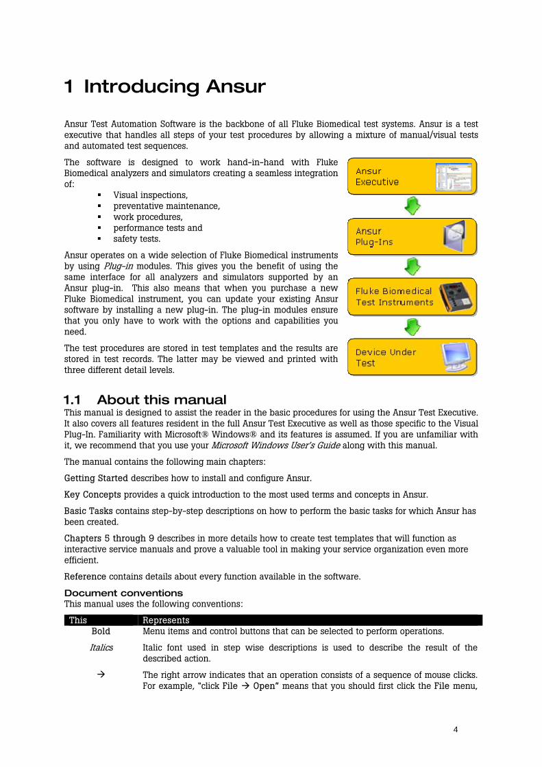
Ansur Test Automation Software is the backbone of all Fluke Biomedical test systems. Ansur is a test executive that handles all steps of your test procedures by allowing a mixture of manual/visual tests and automated test sequences.
The software is designed to work hand-in-hand with Fluke Biomedical analyzers and simulators creating a seamless integration of:
Visual inspections, preventative maintenance, work procedures, performance tests and safety tests.
Ansur operates on a wide selection of Fluke Biomedical instruments by using Plug-in modules. This gives you the benefit of using the same interface for all analyzers and simulators supported by an Ansur plug-in. This also means that when you purchase a new Fluke Biomedical instrument, you can update your existing Ansur software by installing a new plug-in. The plug-in modules ensure that you only have to work with the options and capabilities you need.
The test procedures are stored in test templates and the results are stored in test records. The latter may be viewed and printed with three different detail levels.
1.1 About this manual This manual is designed to assist the reader in the basic procedures for using the Ansur Test Executive. It also covers all features resident in the full Ansur Test Executive as well as those specific to the Visual Plug-In. Familiarity with Microsoft® Windows® and its features is assumed. If you are unfamiliar with it, we recommend that you use your Microsoft Windows User’s Guide along with this manual.
The manual contains the following main chapters:
Getting Started describes how to install and configure Ansur.
Key Concepts provides a quick introduction to the most used terms and concepts in Ansur.
Basic Tasks contains step-by-step descriptions on how to perform the basic tasks for which Ansur has been created.
Chapters 5 through 9 describes in more details how to create test templates that will function as interactive service manuals and prove a valuable tool in making your service organization even more efficient.
Reference contains details about every function available in the software.
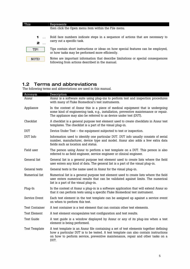
Document conventions This manual uses the following conventions:
This Represents Bold Menu items and control buttons that can be selected to perform operations.
Italics Italic font used in step wise descriptions is used to describe the result of the described action.
The right arrow indicates that an operation consists of a sequence of mouse clicks. For example, “click File Open” means that you should first click the File menu,
5
This Represents then click the Open menu item within the File menu.
1 …
2 …
Bold face numbers indicate steps in a sequence of actions that are necessary to carry out a specific task.
TIP! Tips contain short instructions or ideas on how special features can be employed, or how tasks may be performed more efficiently.
NOTE! Notes are important information that describe limitations or special consequences following from actions described in the manual.
1.2 Terms and abbreviations The following terms and abbreviations are used in this manual.
Acronym Description Ansur Ansur is a software suite using plug-ins to perform test and inspection procedures
with many of Fluke Biomedical’s test instruments.
Appliance In the context of Ansur this is a piece of medical equipment that is undergoing some kind of engineering task, e.g., installation, preventive maintenance or repair. The appliance may also be referred to as device under test (DUT).
Checklist A checklist is a general purpose test element used to create checklists in Ansur test templates. The checklist is a part of the visual plug-in.
DUT Device Under Test – the equipment subjected to test or inspection.
DUT Info Information used to identify one particular DUT. DUT info usually consists of serial number, manufacturer, device type and model. Ansur also adds a few extra data fields such as location and status.
Field user The person using Ansur to perform a test template on a DUT. This person is also referred to as field engineer, service engineer or clinical engineer.
General list General list is a general purpose test element used to create lists where the field user enters any kind of data. The general list is a part of the visual plug-in.
General tests General tests is the name used in Ansur for the visual plug-in.
Numerical list Numerical list is a general purpose test element used to create lists where the field user enters numerical results that can be validated against limits. The numerical list is a part of the visual plug-in.
Plug-In In the context of Ansur a plug-in is a software application that will extend Ansur so that it can perform tests using a specific Fluke Biomedical test instrument.
Service Event Each test element in the test template can be assigned up against a service event on when to perform this test.
Test Container A test container is a test element that can contain other test elements.
Test Element A test element encapsulates test configuration and test results.
Test Guide A test guide is a window displayed by Ansur or any of its plug-ins when a test element is being performed.
Test Template A test template is an Ansur file containing a set of test elements together defining how a particular DUT is to be tested. A test template can also contain instructions on how to perform service, preventive maintenance, repair and other tasks on a DUT.

6
Acronym Description Test Sequence A test sequence contains a test template as well as additional information about
the test and the DUT. This information could include any information about the product being tested, specifics about the template itself, or the result data that is compiled after the test runs.
Test Setup The test sequence contains a tab labeled test setup and here the information for the device under test (DUT info) is placed. Related documents for the device can be linked up, and also Plug-in test setup is entered here.
Test Record A test record is an Ansur file containing the results of a performed test template. The test record can be printed as a test report.
Visual plug-in The visual plug-in is a part of Ansur that contains the test elements checklist, numerical list, general list, test container and user message.
Visual tests Visual tests is often used as a common name for all test elements provided by the visual plug-in.
7
2 Getting Started
This chapter will tell you how to get started using Ansur.
NOTE! If you plan to use Ansur with one or more test instruments you will need to install additional plug-ins.
Plug-ins for your test instruments can be downloaded from Fluke Biomedical’s web site: http://www.flukebiomedical.com.
2.1 Installing Ansur Ansur must be installed on your computer before you can use the features described in this user manual. Please contact your local Fluke Biomedical representative or refer to the Fluke Biomedical web site (http://www.flukebiomedical.com) for information on how to retrieve Ansur.
NOTE! You must have administrator privileges on your computer in order to install Ansur. If you do not have administrator privileges you must contact your company’s system administrator.
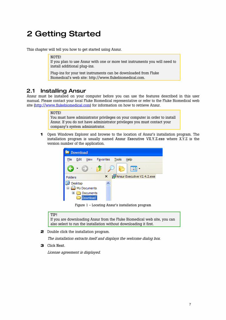
1 Open Windows Explorer and browse to the location of Ansur’s installation program. The installation program is usually named Ansur Executive VX.Y.Z.exe where X.Y.Z is the version number of the application.
Figure 1 - Locating Ansur’s installation program
TIP! If you are downloading Ansur from the Fluke Biomedical web site, you can also select to run the installation without downloading it first.
2 Double click the installation program.
The installation extracts itself and displays the welcome dialog box.
3 Click Next.
License agreement is displayed.
8
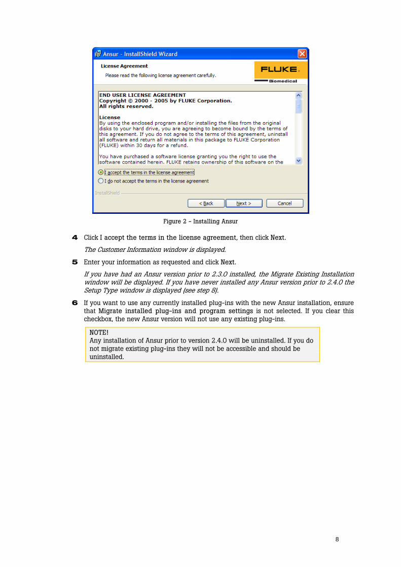
Figure 2 - Installing Ansur
4 Click I accept the terms in the license agreement, then click Next.
The Customer Information window is displayed.
5 Enter your information as requested and click Next.
If you have had an Ansur version prior to 2.3.0 installed, the Migrate Existing Installation window will be displayed. If you have never installed any Ansur version prior to 2.4.0 the Setup Type window is displayed (see step 8).
6 If you want to use any currently installed plug-ins with the new Ansur installation, ensure that Migrate installed plug-ins and program settings is not selected. If you clear this checkbox, the new Ansur version will not use any existing plug-ins.
NOTE! Any installation of Ansur prior to version 2.4.0 will be uninstalled. If you do not migrate existing plug-ins they will not be accessible and should be uninstalled.

9
Figure 3 - Installing Ansur: Migrating an old installation
7 Click Next.
The Setup Type window is displayed.
Figure 4 - Installing Ansur: Setup type
8 Select Complete setup type and click Next. If you want to change the destination folder or remove samples from the installation you must select Custom setup type. However, the Complete selection is recommended.
The Ready to Install window is displayed.
9 Click Install to begin installation.
Installing Ansur window is shown with a progress bar that indicates how the installation is commencing.
10
10 Click Finish.
Ansur is now installed on your computer.
2.2 Entering license key Before you start using Ansur to perform test and inspections you should enter the license key provided by your Fluke Biomedical representative.
NOTE! Even without a license key you can still create test templates and go through a lot of the tasks described in this user manual. However, without licensing Ansur you will not be able to save or print test records.
If you have the license key for an Ansur plug-in you do not need to provide a license for the Ansur Executive. Install the plug-in and provide its license key and Ansur will automatically grant you a license for Ansur Executive.
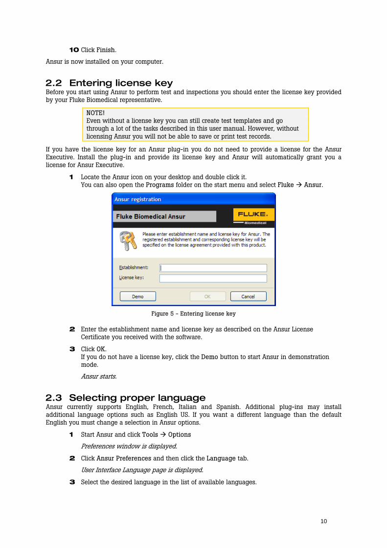
1 Locate the Ansur icon on your desktop and double click it. You can also open the Programs folder on the start menu and select Fluke Ansur.
Figure 5 - Entering license key
2 Enter the establishment name and license key as described on the Ansur License Certificate you received with the software.
3 Click OK. If you do not have a license key, click the Demo button to start Ansur in demonstration mode.
Ansur starts.
2.3 Selecting proper language Ansur currently supports English, French, Italian and Spanish. Additional plug-ins may install additional language options such as English US. If you want a different language than the default English you must change a selection in Ansur options.
1 Start Ansur and click Tools Options
Preferences window is displayed.
2 Click Ansur Preferences and then click the Language tab.
User Interface Language page is displayed.
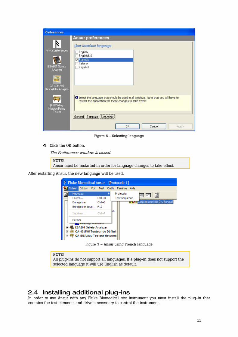
3 Select the desired language in the list of available languages.
11
Figure 6 - Selecting language
4 Click the OK button.
The Preferences window is closed.
NOTE! Ansur must be restarted in order for language changes to take effect.
After restarting Ansur, the new language will be used.
Figure 7 – Ansur using French language
NOTE! All plug-ins do not support all languages. If a plug-in does not support the selected language it will use English as default.
2.4 Installing additional plug-ins In order to use Ansur with any Fluke Biomedical test instrument you must install the plug-in that contains the test elements and drivers necessary to control the instrument.
12
1 Locate and download the installation program for the plug-in corresponding with your test instrument(s) from Fluke Biomedical’s web site (http://www.flukebiomedical.com).
2 Follow a procedure similar to the one described in section 2.1 Installing Ansur to install the plug-in.
Plug-in is installed with ansur.
TIP! If you download the user manual for the plug-in you will find detailed installation instruction in the Getting Started section of the plug-in’s user manual.
3 Start Ansur and enter license key as described in the plug-in’s user manual.
Plug-in is loaded with Ansur and its test elements are available in the Ansur Explorer.
2.5 Uninstalling Ansur Uninstalling Ansur must be performed using the Control Panel.
1 Open Control Panel from Windows’ start menu and double click Add or Remove programs.
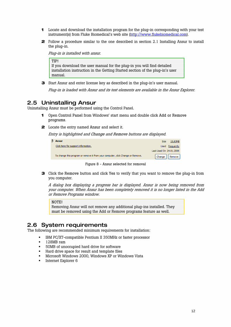
2 Locate the entry named Ansur and select it.
Entry is highlighted and Change and Remove buttons are displayed.
Figure 8 - Ansur selected for removal
3 Click the Remove button and click Yes to verify that you want to remove the plug-in from you computer.
A dialog box displaying a progress bar is displayed. Ansur is now being removed from your computer. When Ansur has been completely removed it is no longer listed in the Add or Remove Programs window.
NOTE! Removing Ansur will not remove any additional plug-ins installed. They must be removed using the Add or Remove programs feature as well.
2.6 System requirements The following are recommended minimum requirements for installation:
IBM PC/XT-compatible Pentium II 350MHz or faster processor 128MB ram 50MB of unoccupied hard drive for software Hard drive space for result and template files Microsoft Windows 2000, Windows XP or Windows Vista Internet Explorer 6
13
3 Key Concepts
Fluke Biomedical Ansur is a ground-breaking application that introduces some new concepts into the business of test, inspection and maintenance. In order to benefit fully from this manual it is necessary that you understand a few of these concepts. This is especially useful if you plan to create your own test templates with Ansur.
TIP! If your purpose of using Ansur is to run a few ready-made templates you may skip this chapter and read section 4.2, 4.3 and 4.4 in chapter 4 Basic Tasks. These sections will give you a quick introduction on how to use Ansur to perform tests and save and print test reports.
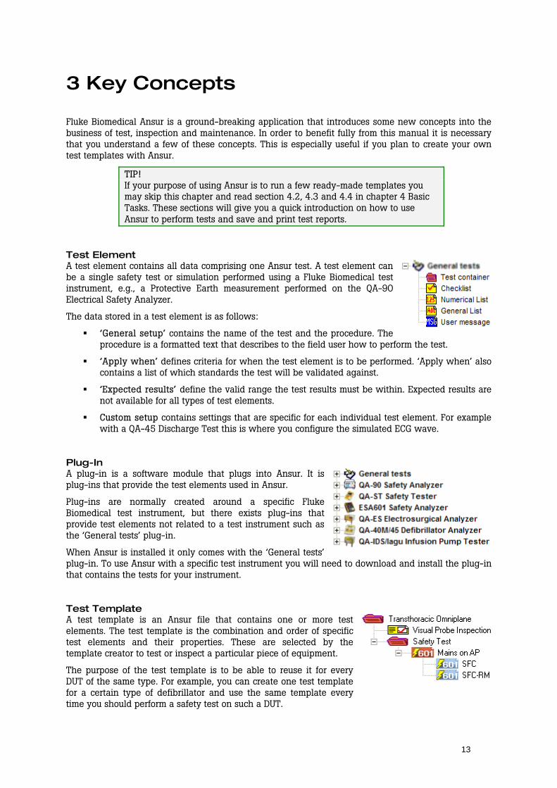
Test Element A test element contains all data comprising one Ansur test. A test element can be a single safety test or simulation performed using a Fluke Biomedical test instrument, e.g., a Protective Earth measurement performed on the QA-90 Electrical Safety Analyzer.
The data stored in a test element is as follows:
‘General setup’ contains the name of the test and the procedure. The procedure is a formatted text that describes to the field user how to perform the test.
‘Apply when’ defines criteria for when the test element is to be performed. ‘Apply when’ also contains a list of which standards the test will be validated against.
‘Expected results’ define the valid range the test results must be within. Expected results are not available for all types of test elements.
Custom setup contains settings that are specific for each individual test element. For example with a QA-45 Discharge Test this is where you configure the simulated ECG wave.
Plug-In A plug-in is a software module that plugs into Ansur. It is plug-ins that provide the test elements used in Ansur.
Plug-ins are normally created around a specific Fluke Biomedical test instrument, but there exists plug-ins that provide test elements not related to a test instrument such as the ‘General tests’ plug-in.
When Ansur is installed it only comes with the ‘General tests’ plug-in. To use Ansur with a specific test instrument you will need to download and install the plug-in that contains the tests for your instrument.
Test Template A test template is an Ansur file that contains one or more test elements. The test template is the combination and order of specific test elements and their properties. These are selected by the template creator to test or inspect a particular piece of equipment.
The purpose of the test template is to be able to reuse it for every DUT of the same type. For example, you can create one test template for a certain type of defibrillator and use the same template every time you should perform a safety test on such a DUT.

14
Test Record When a test template has been performed it becomes a test record. The test record can contain any data gathered while testing a piece of equipment, the test template used to test the equipment and any information that was entered into the test sequence prior to testing.
While the information is available to view, copy or print, anything that was entered into the template or sequence prior to the testing, or information gathered during the test/inspection cannot be manipulated in any way.
A test record will always have an overall status indicating whether all tests passed or any test failed.
Test Sequence A test sequence is the combination of a test template and the specific device information that accompanies a test template. This information could include any information about the product being tested, specifics about the template itself, or the result data that is compiled after the test runs.
A test sequence can be used to perform a test instead of a test template.
Service Events Service events are created on a test template and are used to define when different tests are to be performed. Using service events you can create one template to handle all tasks that need be carried out on a specific type of appliance.
When the template is performed, the field user will specify the service event currently being carried out. Ansur will make sure that only the tests valid for the current operation are presented to the user.
Procedure Each test element permits a descriptive procedure that explains its execution.
The written procedure can be formatted using Ansur’s built in word processor, and it can be enhanced with pictures, different fonts and colors.
The procedure is edited in a test element’s General setup and is displayed in the Test Guide when the test is performed.
Test Guide The Test Guide is displayed for each test element when an Ansur test template is performed.
The Test Guide displays the test’s procedure which describes for the field user how the test is to be carried out.
The Test Guide also displays the test results as well as additional information such as DUT info and comments.
15
4 Basic Tasks
This chapter describes the basic tasks you need to know in order to operate Ansur.
TIP! If you have no interest in the features used to create new tests, but only plan to run existing tests only, then sections 4.1 through 4.4 will be of interest. You may want to read section 10.5 Test Guide on page 80 for more information on how to run tests using Ansur.
4.1 Loading an Ansur file Ansur uses three different files to store test setup and result data.
Test templates define how a DUT is to be tested. They are stored with the file extension .mtt.
Test sequences contain a test template together with information about the DUT that is to be tested such as its serial number and location. Test sequences are stored with the file extension .mts.
Test records contain a test sequence together with test results when a test has been performed. Test records are stored with the file extension .mtr.
TIP! You can open an Ansur file by double clicking it in the Windows Explorer.
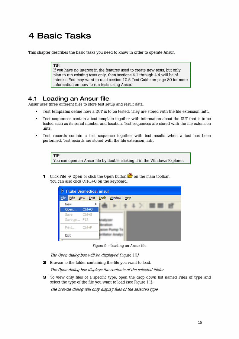
1 Click File Open or click the Open button on the main toolbar. You can also click CTRL+O on the keyboard.
Figure 9 - Loading an Ansur file
The Open dialog box will be displayed (Figure 10).
2 Browse to the folder containing the file you want to load.
The Open dialog box displays the contents of the selected folder.
3 To view only files of a specific type, open the drop down list named Files of type and select the type of the file you want to load (see Figure 11).
The browse dialog will only display files of the selected type.

16
Figure 10 - Browsing for an Ansur file
Figure 11 - Selecting file type to load
4 Click a file name and then click the Open button, or double click the file name.
Ansur loads the selected template and displays its contents.
Figure 12 - Ansur with a test template loaded
4.2 Running a test template Several ready-to-use test templates are copied to the Ansur Test Library folder when you install Ansur. These test templates contain sample test and inspection procedures for a wide variety of hospital equipment. You can load and run the templates in Ansur Test Library without further editing.
17
If you have installed additional plug-ins there may be sub folders containing complete safety tests for the most common standards supported by the actual test instrument.
TIP! You can also use these templates as a foundation when creating new, customized test templates. Load a template from the test library then use Save As to give it another name. Now you can add new visual inspections and safety test to suit the needs of your organization.
Load a test template 1 Click File Open or click the Open button on the main toolbar.
You can also click CTRL+O on the keyboard.
The Open dialog box will be displayed.
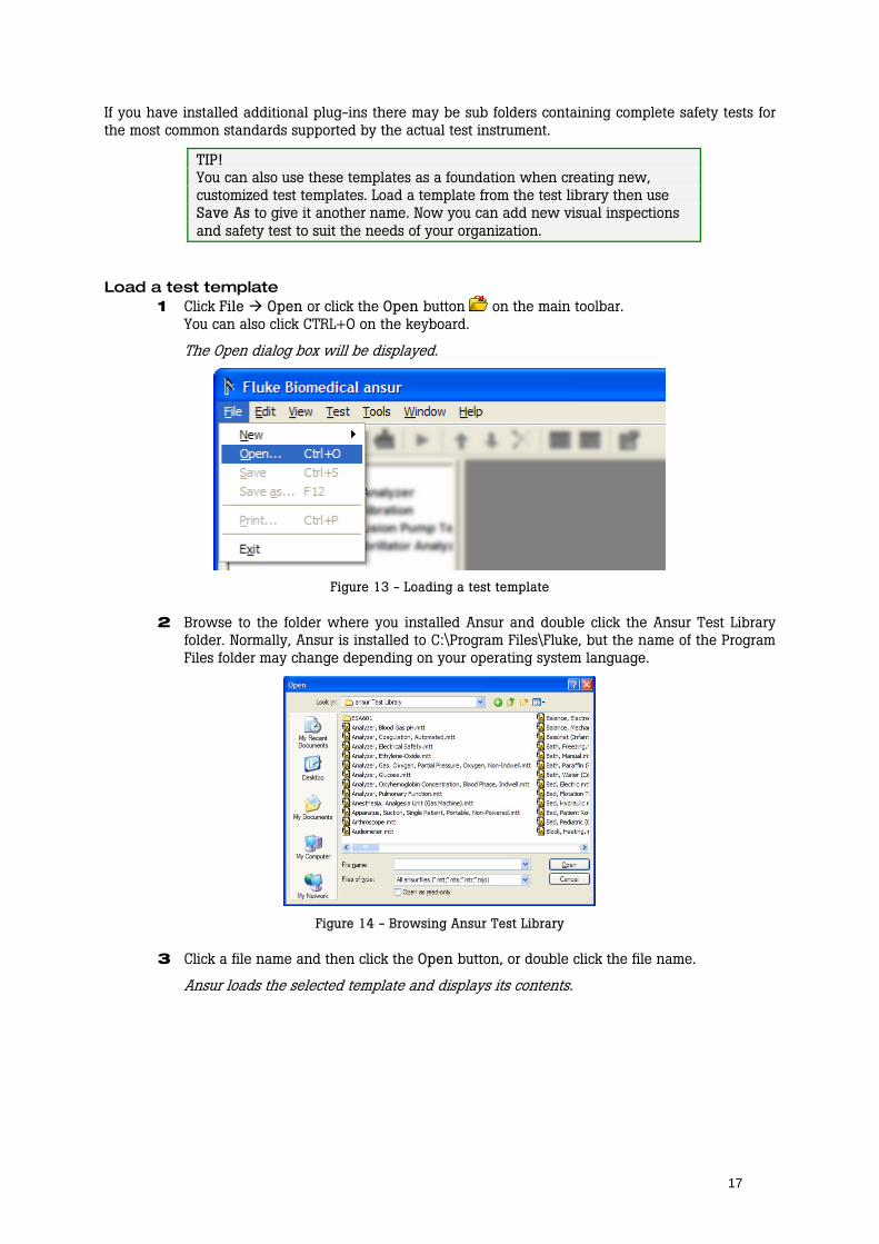
Figure 13 - Loading a test template
2 Browse to the folder where you installed Ansur and double click the Ansur Test Library folder. Normally, Ansur is installed to C:\Program Files\Fluke, but the name of the Program Files folder may change depending on your operating system language.
Figure 14 - Browsing Ansur Test Library
3 Click a file name and then click the Open button, or double click the file name.
Ansur loads the selected template and displays its contents.
18
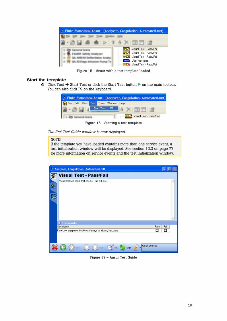
Figure 15 - Ansur with a test template loaded
Start the template 4 Click Test Start Test or click the Start Test button on the main toolbar.
You can also click F9 on the keyboard.
Figure 16 - Starting a test template
The first Test Guide window is now displayed.
NOTE! If the template you have loaded contains more than one service event, a test initialization window will be displayed. See section 10.3 on page 77 for more information on service events and the test initialization window.
Figure 17 – Ansur Test Guide

19
Perform the tests 5 Follow the instructions displayed in the Test Guide to complete each step. For automatic
safety tests you may have to click the Start Test button on the Test Guide’s toolbar to get the test running.
When the test step is completed the Next button on the toolbar will be enabled and the toolbar will display the status of the test.
NOTE! Test elements from other plug-ins may require specific set up operations to be completed before the test can be run. These specifics are described in the plug-in’s user manual.
Figure 18 - Test Guide's toolbar when a test has been completed
6 Click the Next button to continue to the next test in the template. You can also press F9 on the keyboard.
The next Test Guide window is displayed.
TIP! If you want to repeat the safety test, click the Back button to return to the previous Test Guide.
7 Repeat the instructions in step 5 and 6 until all tests have been completed.
Complete the test 8 When you click the Next button on the last test element the Test Summary window is
displayed.
Test Summary window is displayed.
Figure 19 - Test Summary window
9 Click the Next button in order to create a Test Record. You can also press F9 on the keyboard.

20
The Test Summary window is closed and a Test Record is opened in the main Ansur window.
Figure 20 - Ansur Test Record
4.3 Storing your data If you are to save the contents of a test record or a test template it must be saved as a file on your computer.
1 Click File Save on the main menu or click the save button on the toolbar. You can also press CTRL+S on the keyboard.
Figure 21 - Saving a test record
21
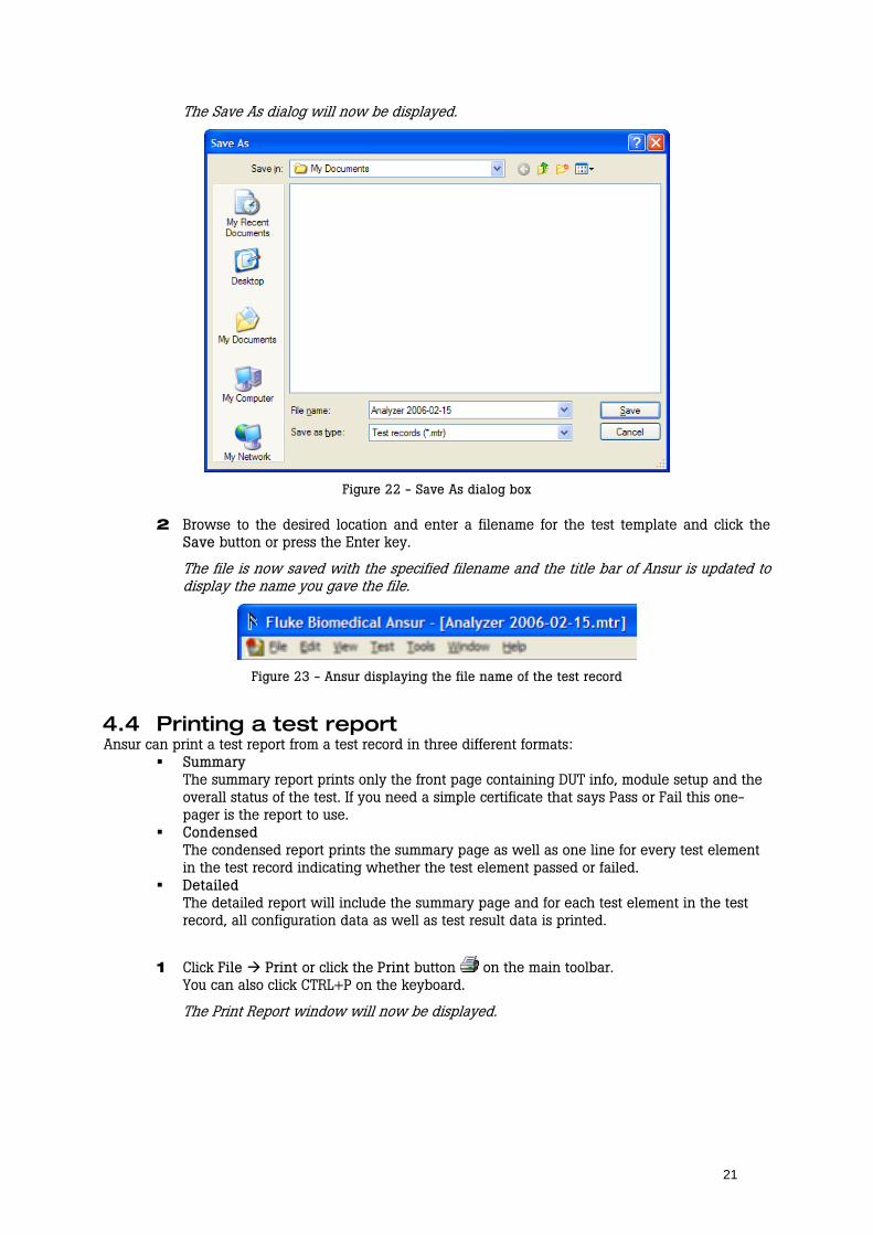
The Save As dialog will now be displayed.
Figure 22 - Save As dialog box
2 Browse to the desired location and enter a filename for the test template and click the Save button or press the Enter key.
The file is now saved with the specified filename and the title bar of Ansur is updated to display the name you gave the file.
Figure 23 - Ansur displaying the file name of the test record
4.4 Printing a test report Ansur can print a test report from a test record in three different formats:
Summary The summary report prints only the front page containing DUT info, module setup and the overall status of the test. If you need a simple certificate that says Pass or Fail this one-pager is the report to use.
Condensed The condensed report prints the summary page as well as one line for every test element in the test record indicating whether the test element passed or failed.
Detailed The detailed report will include the summary page and for each test element in the test record, all configuration data as well as test result data is printed.
1 Click File Print or click the Print button on the main toolbar. You can also click CTRL+P on the keyboard.
The Print Report window will now be displayed.
22
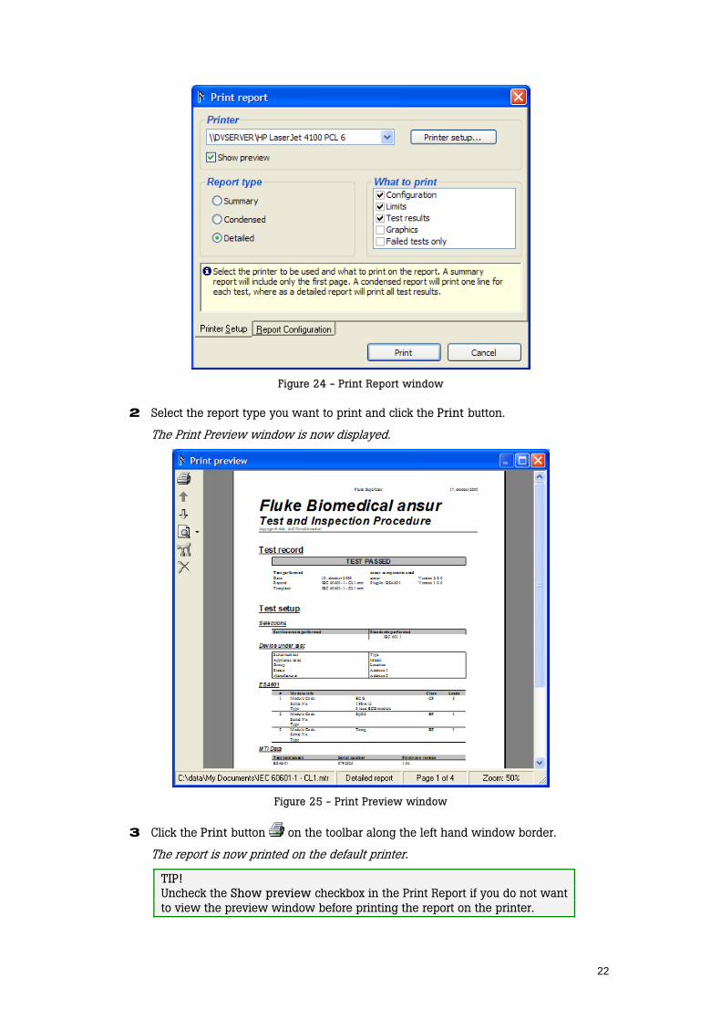
Figure 24 - Print Report window
2 Select the report type you want to print and click the Print button.
The Print Preview window is now displayed.
Figure 25 - Print Preview window
3 Click the Print button on the toolbar along the left hand window border.
The report is now printed on the default printer.
TIP! Uncheck the Show preview checkbox in the Print Report if you do not want to view the preview window before printing the report on the printer.

23
4.5 Creating a checklist A checklist is a test element that displays a list where each item can be given a status Pass or Fail.
Create an empty test template Normally, Ansur will open with a blank test template and you can start defining your template there. If you have closed the blank template (and the main window contains a big dark gray frame) you will have to create a new test template.
1 Click File New Template or click the New Template button on the main toolbar.
Figure 26 - Creating a new test template
A blank template will now be displayed in Ansur’s main window.
Add a checklist to the template In order to create a test template comprising several tests and/or inspections, you must add tests to the template from Ansur Text Explorer.
2 Click the plus button next to the plug-in name in Ansur’s Test Explorer in order to access the test elements provided by the plug-in.
The plug-in entry expands and displays a list of provided tests.
3 Click and hold the left mouse button on the Checklist element found under the heading General tests.
4 Without releasing the mouse button, drag the test element onto the blank test template.
The test element is highlighted, and the mouse pointer changes to a drop cursor.
Figure 27 - Creating a checklist
5 Release the left mouse button.
A copy of the test element is shown in the test template window.
24
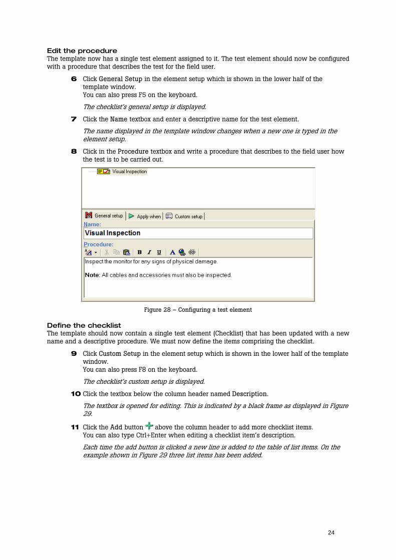
Edit the procedure The template now has a single test element assigned to it. The test element should now be configured with a procedure that describes the test for the field user.
6 Click General Setup in the element setup which is shown in the lower half of the template window. You can also press F5 on the keyboard.
The checklist’s general setup is displayed.
7 Click the Name textbox and enter a descriptive name for the test element.
The name displayed in the template window changes when a new one is typed in the element setup.
8 Click in the Procedure textbox and write a procedure that describes to the field user how the test is to be carried out.
Figure 28 – Configuring a test element
Define the checklist The template should now contain a single test element (Checklist) that has been updated with a new name and a descriptive procedure. We must now define the items comprising the checklist.
9 Click Custom Setup in the element setup which is shown in the lower half of the template window. You can also press F8 on the keyboard.
The checklist’s custom setup is displayed.
10 Click the textbox below the column header named Description.
The textbox is opened for editing. This is indicated by a black frame as displayed in Figure 29.
11 Click the Add button above the column header to add more checklist items. You can also type Ctrl+Enter when editing a checklist item’s description.
Each time the add button is clicked a new line is added to the table of list items. On the example shown in Figure 29 three list items has been added.

25
Figure 29 - Defining the checklist
Preview the checklist In order to see how the checklist will look for the field user you can preview it in the Test Guide.
12 Select View Preview test element from Ansur’s main menu.
The Test Guide for the checklist is displayed.
Figure 30 - Preview menu
13 Click the Abort button in order to return to the test template. You must click Yes when Ansur asks whether you want to abort the test template.
The Test Guide for the checklist disappears.
Figure 31 - Test guide previewing a checklist
TIP! Remember to save your changes on a regular basis, e.g., after verifying the preview of the checklist. Click the save button on the toolbar, or press Ctrl+S on your keyboard. See also section 4.3 Storing your data.

26
4.6 Creating a numerical list A numerical list is a test element that displays a list where the field user must enter a numerical value for each item. Each item in the list can be assigned a high and low limit against which the entered results will be validated.
In this section we will add a numerical list to the template created in section 4.5 Creating a checklist. For information on how to create a new test template see Create an empty test template on page 23.
Add a numerical list to a template 1 Locate the Numerical List test element listed under the General tests plug-in in Ansur
Test Explorer.
2 Click and hold the left mouse button on the test element in the Test Explorer.
3 Without releasing the mouse button, drag the test element onto the test template.
The test element is highlighted, and the mouse pointer changes to a drop cursor.
4 Release the left mouse button.
A copy of the test element is shown in the test template window.
Figure 32 - Adding a numerical list
Edit the procedure 5 Click General Setup in the element setup which is shown in the lower half of the
template window. You can also press F5 on the keyboard.
The numerical list’s general setup is displayed.
6 Click the Name textbox and enter a descriptive name for the test element.
The name displayed in the template window changes when a new one is typed in the element setup.
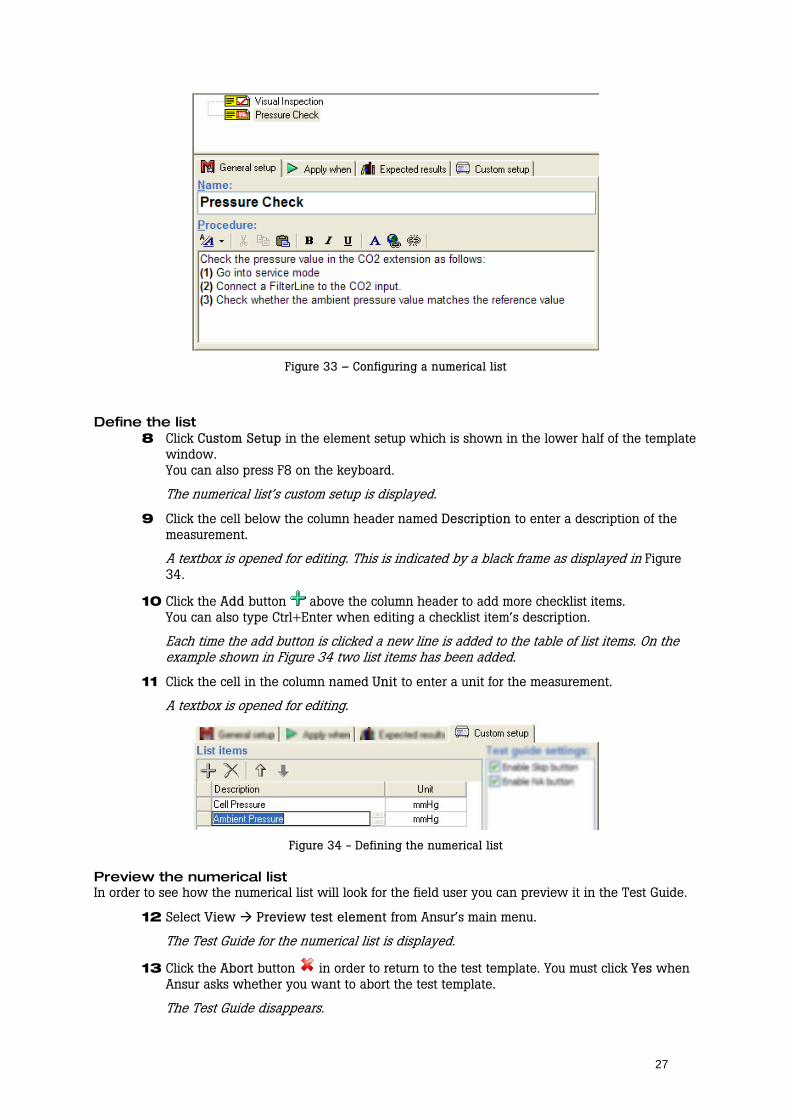
7 Click in the Procedure textbox and write a procedure that describes to the field user how the test is to be carried out.
27
Figure 33 – Configuring a numerical list
Define the list 8 Click Custom Setup in the element setup which is shown in the lower half of the template
window. You can also press F8 on the keyboard.
The numerical list’s custom setup is displayed.
9 Click the cell below the column header named Description to enter a description of the measurement.
A textbox is opened for editing. This is indicated by a black frame as displayed in Figure 34.
10 Click the Add button above the column header to add more checklist items. You can also type Ctrl+Enter when editing a checklist item’s description.
Each time the add button is clicked a new line is added to the table of list items. On the example shown in Figure 34 two list items has been added.
11 Click the cell in the column named Unit to enter a unit for the measurement.
A textbox is opened for editing.
Figure 34 - Defining the numerical list
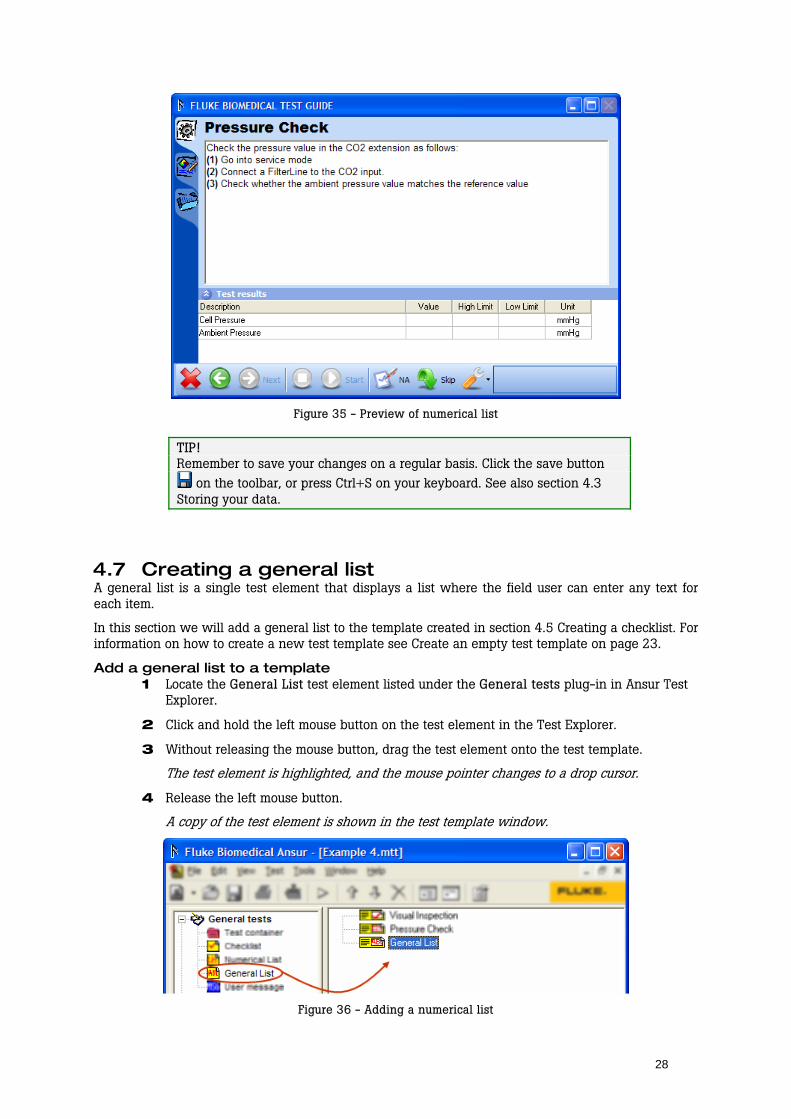
Preview the numerical list In order to see how the numerical list will look for the field user you can preview it in the Test Guide.
12 Select View Preview test element from Ansur’s main menu.
The Test Guide for the numerical list is displayed.
13 Click the Abort button in order to return to the test template. You must click Yes when Ansur asks whether you want to abort the test template.
The Test Guide disappears.
28
Figure 35 - Preview of numerical list
TIP! Remember to save your changes on a regular basis. Click the save button
on the toolbar, or press Ctrl+S on your keyboard. See also section 4.3 Storing your data.
4.7 Creating a general list A general list is a single test element that displays a list where the field user can enter any text for each item.
In this section we will add a general list to the template created in section 4.5 Creating a checklist. For information on how to create a new test template see Create an empty test template on page 23.
Add a general list to a template 1 Locate the General List test element listed under the General tests plug-in in Ansur Test
Explorer.
2 Click and hold the left mouse button on the test element in the Test Explorer.
3 Without releasing the mouse button, drag the test element onto the test template.
The test element is highlighted, and the mouse pointer changes to a drop cursor.
4 Release the left mouse button.
A copy of the test element is shown in the test template window.
Figure 36 - Adding a numerical list

29
Edit the procedure 5 Click General Setup in the element setup which is shown in the lower half of the
template window. You can also press F5 on the keyboard.
The general list’s general setup is displayed.
6 Click the Name textbox and enter a descriptive name for the test element.
The name displayed in the template window changes when a new one is typed in the element setup.
7 Click in the Procedure textbox and write a procedure that describes to the field user how the test is to be carried out.
Figure 37 – Configuring a general list
Define the list 8 Click Custom Setup in the element setup which is shown in the lower half of the template
window. You can also press F8 on the keyboard.
The general list’s custom setup is displayed.
9 Click the cell below the column header named Description to enter a description of the item.
A textbox is opened for editing. This is indicated by a black frame as displayed in Figure 34.
10 Click the Add button above the column header to add more checklist items. You can also type Ctrl+Enter when editing a checklist item’s description.
Each time the add button is clicked a new line is added to the table of list items. On the example shown in Figure 38 three list items has been added.
11 Click the cell in the column named Unit to enter a unit for the measurement.
A textbox is opened for editing.
30
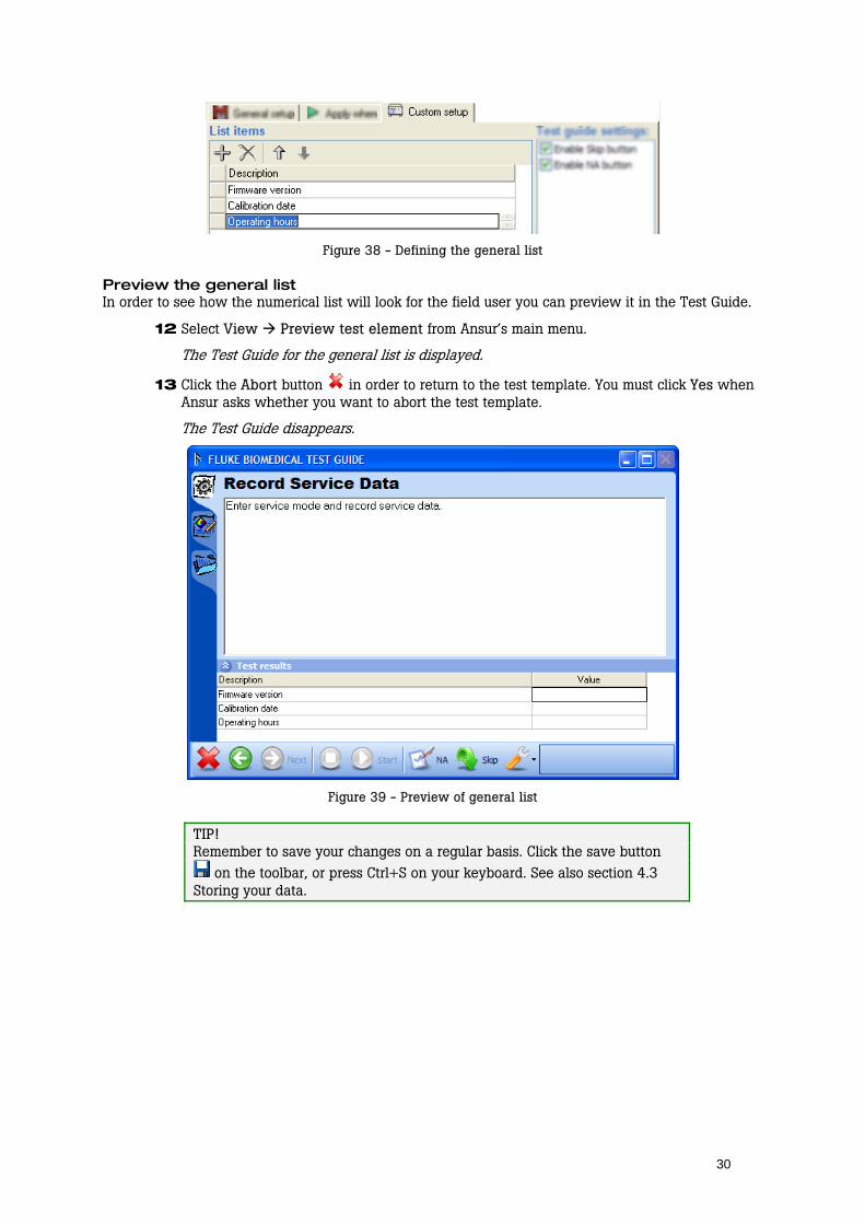
Figure 38 - Defining the general list
Preview the general list In order to see how the numerical list will look for the field user you can preview it in the Test Guide.
12 Select View Preview test element from Ansur’s main menu.
The Test Guide for the general list is displayed.
13 Click the Abort button in order to return to the test template. You must click Yes when Ansur asks whether you want to abort the test template.
The Test Guide disappears.
Figure 39 - Preview of general list
TIP! Remember to save your changes on a regular basis. Click the save button
on the toolbar, or press Ctrl+S on your keyboard. See also section 4.3 Storing your data.
31
5 Working with Procedures
Each test element permits a descriptive procedure to be added that explains how the test is to be executed. The written procedure can be formatted using Ansur’s built in word processor, and it can be enhanced with pictures, different fonts and colors. The procedure is edited in a test element’s General setup and is displayed in the Test Guide when the test is performed.
Ansur supports using plain text, RTF or HTML in test element procedures. Plain text does not support text formatting or pictures. Hence it is fastest and best suited if your field users are using old computers. RTF is best suited for printed reports and HTML is best for viewing on the web.
The instructions in this chapter assume that you are familiar with the basic tasks described in chapter 4 starting on page 15.
5.1 Displaying a picture in a procedure In this section we will create a formatted test procedure with an inline picture. We will use HTML as the format of our procedure.
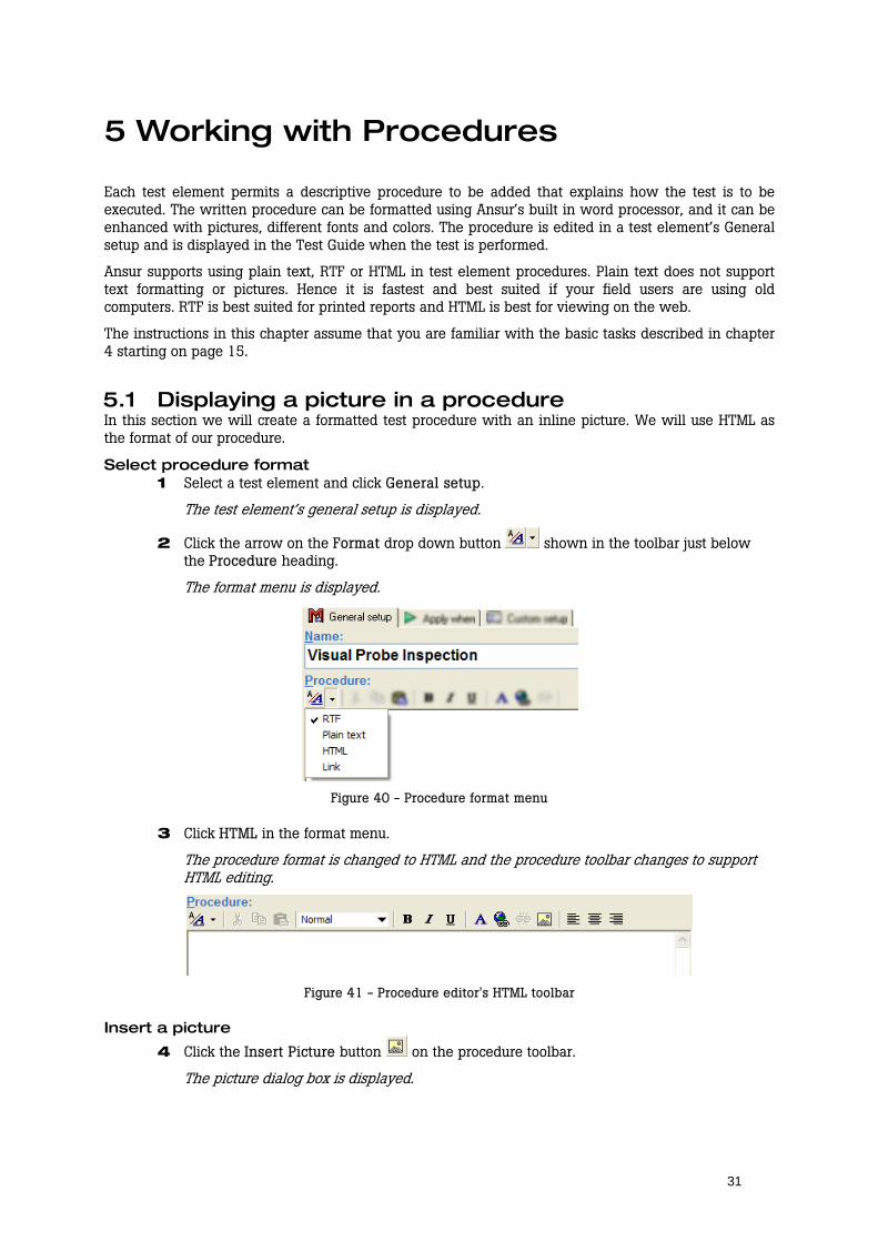
Select procedure format 1 Select a test element and click General setup.
The test element’s general setup is displayed.
2 Click the arrow on the Format drop down button shown in the toolbar just below the Procedure heading.
The format menu is displayed.
Figure 40 - Procedure format menu
3 Click HTML in the format menu.
The procedure format is changed to HTML and the procedure toolbar changes to support HTML editing.
Figure 41 - Procedure editor's HTML toolbar
Insert a picture
4 Click the Insert Picture button on the procedure toolbar.
The picture dialog box is displayed.

32
Figure 42 - Procedure editor's picture dialog box
5 Click the Browse button
A file dialog is shown
Figure 43 - Select picture file
6 Locate the picture to be inserted into the procedure. Click its filename and then click the Open button. You can also double click the filename.
The filename is now displayed as Picture Source in the picture dialog box. This example uses a JPEG image named probe.jpg stored in the folder c:\templates\pictures.
NOTE! Pictures referenced by Ansur must be stored in the same location on every computer that is to use the template. It is therefore a good idea to create a common location for all pictures used in Ansur templates.
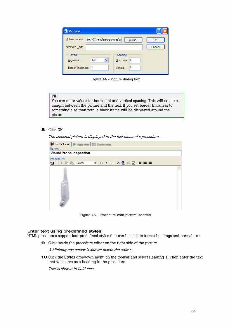
7 Click the dropdown named Alignment and select Left in the dropdown menu.
This will make the picture be aligned against the left margin of the procedure and allow text on the right side of the picture.
33
Figure 44 - Picture dialog box
TIP! You can enter values for horizontal and vertical spacing. This will create a margin between the picture and the text. If you set border thickness to something else than zero, a black frame will be displayed around the picture.
8 Click OK.
The selected picture is displayed in the test element’s procedure.
Figure 45 - Procedure with picture inserted
Enter text using predefined styles HTML procedures support four predefined styles that can be used to format headings and normal text.
9 Click inside the procedure editor on the right side of the picture.
A blinking text cursor is shown inside the editor.
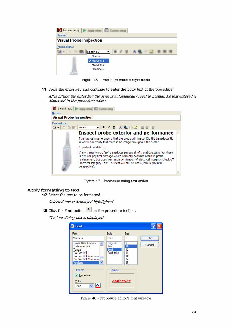
10 Click the Styles dropdown menu on the toolbar and select Heading 1. Then enter the text that will serve as a heading in the procedure.
Text is shown in bold face.
34
Figure 46 - Procedure editor's style menu
11 Press the enter key and continue to enter the body text of the procedure.
After hitting the enter key the style is automatically reset to normal. All text entered is displayed in the procedure editor.
Figure 47 - Procedure using text styles
Apply formatting to text 12 Select the text to be formatted.
Selected text is displayed highlighted.
13 Click the Font button on the procedure toolbar.
The font dialog box is displayed.
Figure 48 - Procedure editor's font window

35
14 Adjust the formatting as desired and click OK.
The selected text is updated with the new formatting.
Figure 49 - Procedure with picture and formatted text
5.2 Inserting a hyperlink in a procedure Every test element procedure in Ansur can contain hyperlinks to other documents. Either to a file stored on the computer or to a web address.
Hyperlinks can only be used in RTF or HTML procedures.
1 Select a test element and click General setup.
The test element’s general setup is displayed.
2 Select the text that is going to be the hyperlink.
The selected text is highlighted.
Figure 50 – Selecting hyperlink text
3 Click Insert Hyperlink on the editor’s toolbar.
The Insert Hyperlink window is displayed.
4 Specify the address of the document that is the target of the hyperlink. The document can be a picture, an HTML document, a PDF document or a Word document.
This example will use a PDF document named D1987A User Manual.pdf stored in the folder c:\templates\documents.
NOTE! If you link to a special file type such as PDF or Word documents, a proper viewer for the document (e.g. Acrobat® Reader or Microsoft® Word) must be installed on the field user’s computer otherwise they will not be able to view it.

36
5 Click OK.
The Insert Hyperlink window disappears and the selected text is underlined in blue.
Figure 51 – Insert hyperlink window
Figure 52 - Procedure with a hyperlink
NOTE! Documents referenced by Ansur must be stored in the same location on every computer that is to use the template. It is therefore a good idea to create a common location for all documents used in Ansur templates.
5.3 Using an external file as a procedure Instead of using Ansur’s internal editor to write test element procedures you can write the procedures in the editor of your choice and link it to a test element procedure. When the test is performed Ansur will display the linked document inside the test’s Test Guide. The document can be an HTML document, a Microsoft® Word® document, a text file, an Adobe® PDF™ document or a picture.
The purpose of the link-to-file procedure is to allow you to use even more advanced formatting in the procedure than supported by Ansur’s editor, e.g. tables.
1 Create a document to be used as a procedure for a test element using the text editor of your choice. Store the document in a known location.
This example will use an HTML document named CalibProc.html stored in the folder c:\templates\procedures.
NOTE! Documents referenced by Ansur must be stored in the same location on every computer that is to use the template. It is therefore a good idea to create a common location for all documents used in Ansur templates.
2 Select a test element and click General setup.
The test element’s general setup is displayed.
3 Click the arrow on the Format drop down button shown in the toolbar just below the Procedure heading. Then click the Link menu.
When the Link item is selected in the format menu, the procedure’s toolbar changes.
37
Figure 53 – Selecting link as procedure format
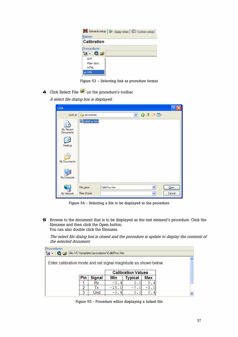
4 Click Select File on the procedure’s toolbar
A select file dialog box is displayed.
Figure 54 - Selecting a file to be displayed in the procedure
5 Browse to the document that is to be displayed as the test element’s procedure. Click the filename and then click the Open button. You can also double click the filename.
The select file dialog box is closed and the procedure is update to display the contents of the selected document.
Figure 55 - Procedure editor displaying a linked file
38
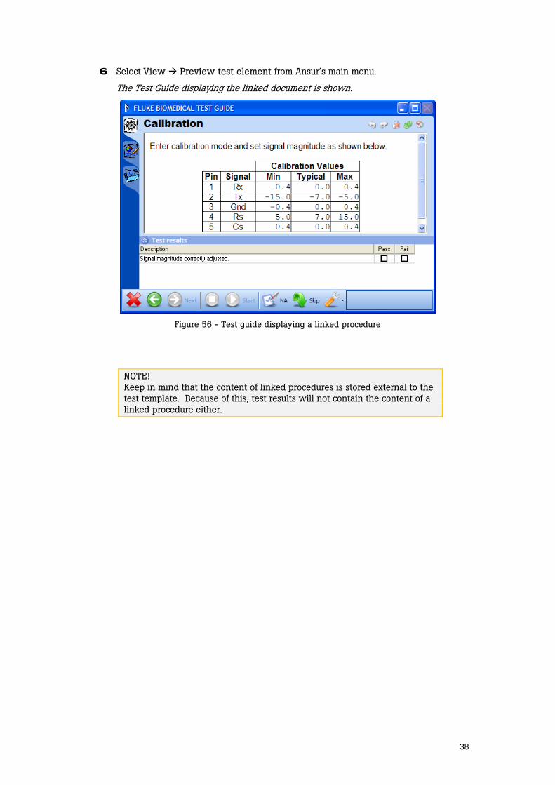
6 Select View Preview test element from Ansur’s main menu.
The Test Guide displaying the linked document is shown.
Figure 56 - Test guide displaying a linked procedure
NOTE! Keep in mind that the content of linked procedures is stored external to the test template. Because of this, test results will not contain the content of a linked procedure either.
39
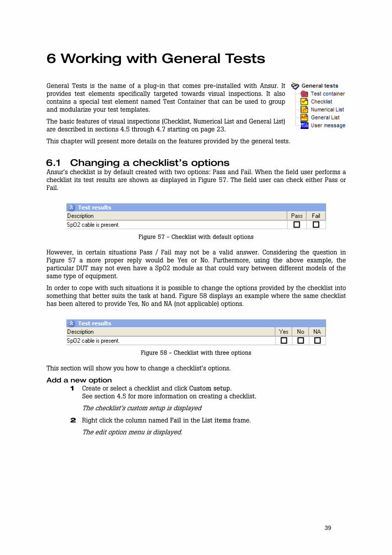
6 Working with General Tests
General Tests is the name of a plug-in that comes pre-installed with Ansur. It provides test elements specifically targeted towards visual inspections. It also contains a special test element named Test Container that can be used to group and modularize your test templates.
The basic features of visual inspections (Checklist, Numerical List and General List) are described in sections 4.5 through 4.7 starting on page 23.
This chapter will present more details on the features provided by the general tests.
6.1 Changing a checklist’s options Ansur’s checklist is by default created with two options: Pass and Fail. When the field user performs a checklist its test results are shown as displayed in Figure 57. The field user can check either Pass or Fail.
Figure 57 - Checklist with default options
However, in certain situations Pass / Fail may not be a valid answer. Considering the question in Figure 57 a more proper reply would be Yes or No. Furthermore, using the above example, the particular DUT may not even have a SpO2 module as that could vary between different models of the same type of equipment.
In order to cope with such situations it is possible to change the options provided by the checklist into something that better suits the task at hand. Figure 58 displays an example where the same checklist has been altered to provide Yes, No and NA (not applicable) options.
Figure 58 - Checklist with three options
This section will show you how to change a checklist’s options.
Add a new option 1 Create or select a checklist and click Custom setup.
See section 4.5 for more information on creating a checklist.
The checklist’s custom setup is displayed
2 Right click the column named Fail in the List items frame.
The edit option menu is displayed.
40
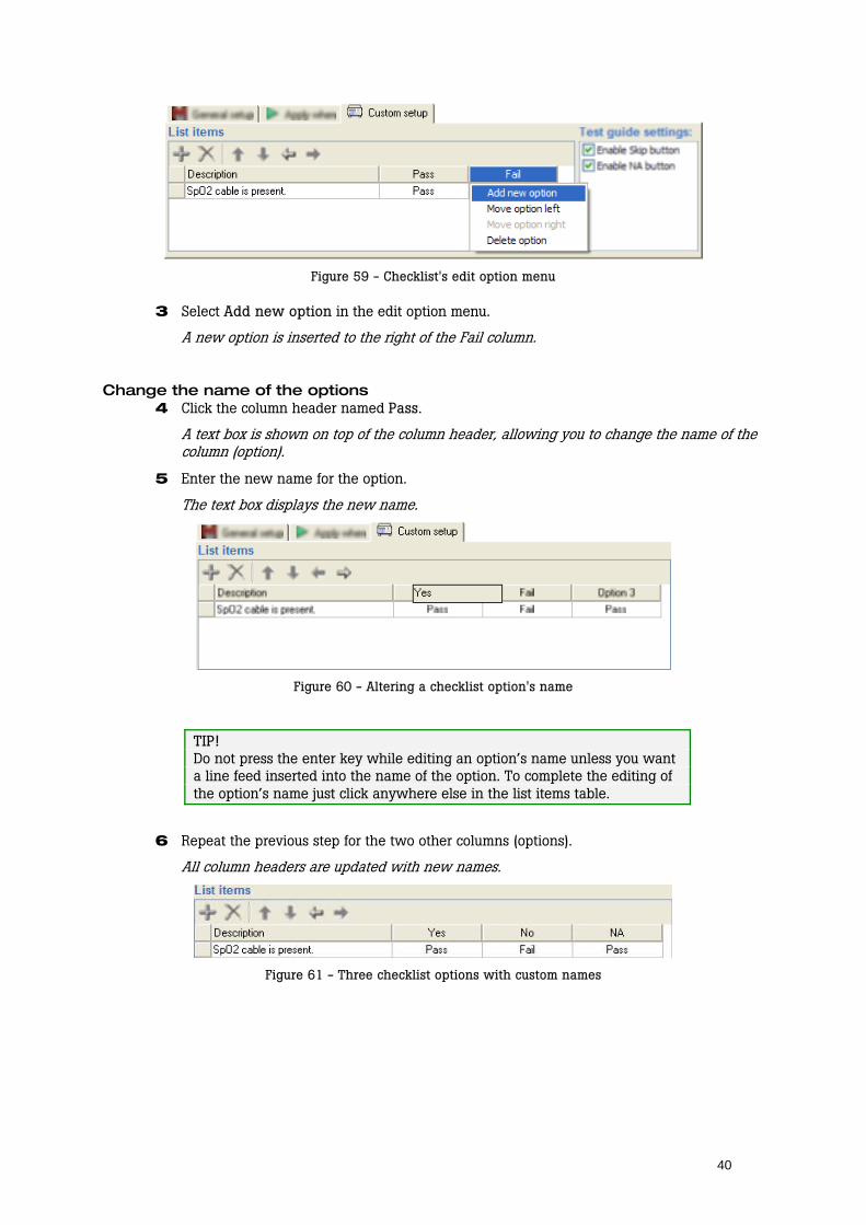
Figure 59 - Checklist's edit option menu
3 Select Add new option in the edit option menu.
A new option is inserted to the right of the Fail column.
Change the name of the options 4 Click the column header named Pass.
A text box is shown on top of the column header, allowing you to change the name of the column (option).
5 Enter the new name for the option.
The text box displays the new name.
Figure 60 - Altering a checklist option's name
TIP! Do not press the enter key while editing an option’s name unless you want a line feed inserted into the name of the option. To complete the editing of the option’s name just click anywhere else in the list items table.
6 Repeat the previous step for the two other columns (options).
All column headers are updated with new names.
Figure 61 - Three checklist options with custom names

41
Alter the status of each option Each cell shown in the list items table that displays a status (Pass or Fail) corresponds to a check box when the checklist is performed by the field user. When you define the checklist you can determine the status that each check box will give the checklist when it is clicked by the user.
For this example we’ll leave the status as is for the Yes and No options, but we will update the status of the NA option to Not Applicable.
7 Click the cell below the column header named NA (see Figure 62).
The cell is highlighted and the option status menu is displayed.
Figure 62 - Checklist's option status menu
8 Click the menu item Not Applicable.
The menu is hidden and the cell is updated with the text Not Applicable.
Figure 63 - New status for one checklist option
TIP! If you plan to add several list items that should have the same status for the options you should set the options first. New items will copy the option status settings of the previous list item.
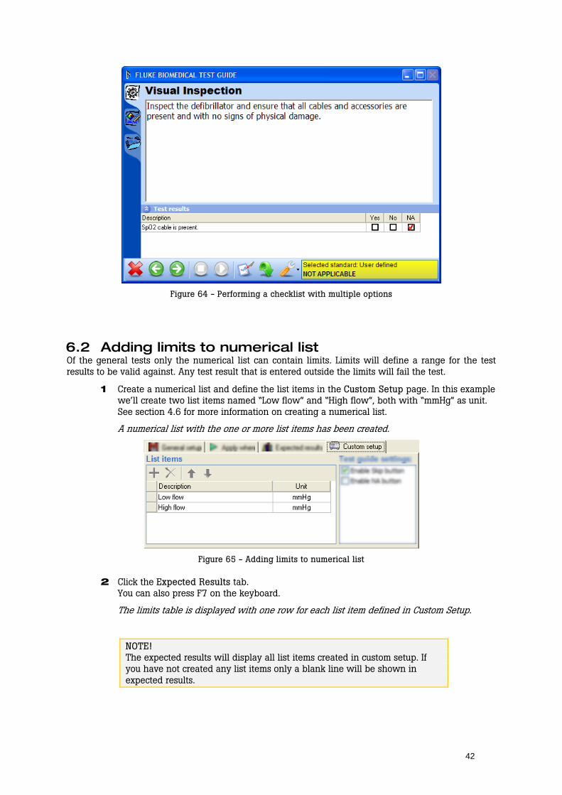
The checklist will now have three options, each with a custom name. If you perform the test and enter results for the checklist you will see that checking the NA column (option) will result in a checklist with an overall status of Not Applicable (see Figure 64).
You may now continue to add new list items as described in Define the checklist on page 24.
42
Figure 64 - Performing a checklist with multiple options
6.2 Adding limits to numerical list Of the general tests only the numerical list can contain limits. Limits will define a range for the test results to be valid against. Any test result that is entered outside the limits will fail the test.
1 Create a numerical list and define the list items in the Custom Setup page. In this example we’ll create two list items named “Low flow” and “High flow”, both with “mmHg” as unit. See section 4.6 for more information on creating a numerical list.
A numerical list with the one or more list items has been created.
Figure 65 - Adding limits to numerical list
2 Click the Expected Results tab. You can also press F7 on the keyboard.
The limits table is displayed with one row for each list item defined in Custom Setup.
NOTE! The expected results will display all list items created in custom setup. If you have not created any list items only a blank line will be shown in expected results.
43
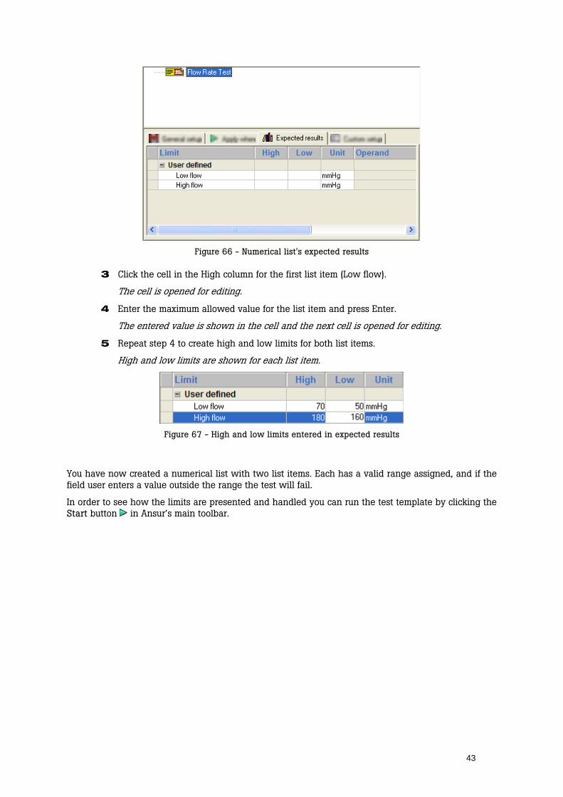
Figure 66 - Numerical list's expected results
3 Click the cell in the High column for the first list item (Low flow).
The cell is opened for editing.
4 Enter the maximum allowed value for the list item and press Enter.
The entered value is shown in the cell and the next cell is opened for editing.
5 Repeat step 4 to create high and low limits for both list items.
High and low limits are shown for each list item.
Figure 67 - High and low limits entered in expected results
You have now created a numerical list with two list items. Each has a valid range assigned, and if the field user enters a value outside the range the test will fail.
In order to see how the limits are presented and handled you can run the test template by clicking the Start button in Ansur’s main toolbar.

44
Figure 68 - Test guide showing a numerical list with limits
6.3 Creating test blocks The ability to create test blocks in Ansur gives you a much preferred hierarchical overview of your test and service procedures. Test blocks can be created using test containers and enable you to group related test elements together. Test blocks are also very handy when you start to use service events as illustrated in section 7.5 starting on page 51.
Create a test container 1 Click the plus button next to the plug-in name in Ansur’s Test Explorer in order to access
the test elements provided by the plug-in.
The plug-in entry expands and displays a list of provided tests.
2 Click and hold the left mouse button on the Test Container element in the Test Explorer
3 Without releasing the mouse button, drag the test element onto the blank test template.
The test element is highlighted, and the mouse pointer changes to a drop cursor.
4 Release the left mouse button.
A copy of the test element is shown in the test template window.
Figure 69 - Creating a test container
45
Name the test container The template now has a single test container assigned to it. The test container should now be configured with a name that describes the test block for the field user.
5 Click General Setup in the element setup which is shown in the lower half of the template window. You can also press F5 on the keyboard.
The test container’s general setup is displayed.
6 Click the Name textbox and enter a descriptive name for the test container.
The name displayed in the template window changes when a new one is typed in the element setup.
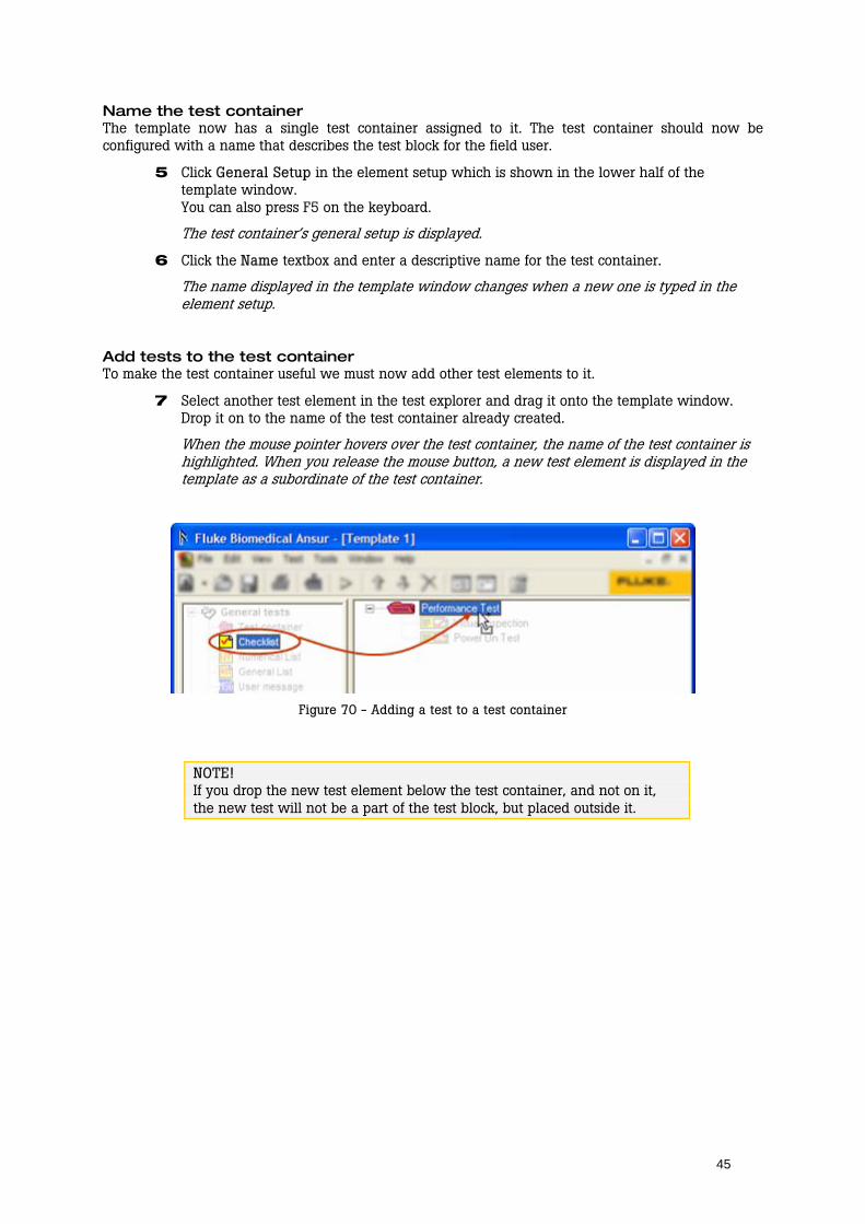
Add tests to the test container To make the test container useful we must now add other test elements to it.
7 Select another test element in the test explorer and drag it onto the template window. Drop it on to the name of the test container already created.
When the mouse pointer hovers over the test container, the name of the test container is highlighted. When you release the mouse button, a new test element is displayed in the template as a subordinate of the test container.
Figure 70 - Adding a test to a test container
NOTE! If you drop the new test element below the test container, and not on it, the new test will not be a part of the test block, but placed outside it.

46
7 Working with Test Templates
A test template is an Ansur file that contains one or more test elements. The test template is the combination and order of specific test elements and their properties. These are selected by the template creator to test or inspect a particular piece of equipment.
This chapter will present more details on working with test templates in Ansur. The basic tasks of creating templates using general tests are described in chapter 4 starting on page 15.
7.1 Moving test elements To move test elements up or down, you will find a group of icons on the main toolbar. On that toolbar you can use the up and down arrow buttons to move elements up and down within the template.
You can also move test elements by clicking and dragging elements within the template.
Test elements can be deleted from a template by selecting the element and then clicking on the Delete button next to the arrow buttons.
Figure 71 - Moving test elements in the template
7.2 Copying test elements If you need several test elements to perform the same test, but maybe with some small changes in the configuration it is a good idea to create one element first and then copy it and change the copy’s settings.
1 Click and hold down the control button on your keyboard.
2 Click the test element you want to copy and hold down the left mouse button while you drag the test element to it’s new location.
The mouse pointer changes to a “copy”-cursor and a horizontal line is displayed in the template window indicating where the test element will be copied.
Figure 72 - Copying a test element
47
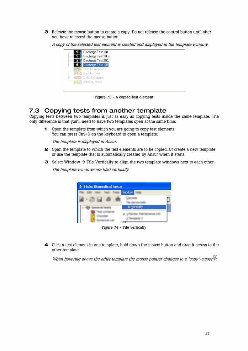
3 Release the mouse button to create a copy. Do not release the control button until after you have released the mouse button.
A copy of the selected test element is created and displayed in the template window.
Figure 73 - A copied test element
7.3 Copying tests from another template Copying tests between two templates is just as easy as copying tests inside the same template. The only difference is that you’ll need to have two templates open at the same time.
1 Open the template from which you are going to copy test elements. You can press Ctrl+O on the keyboard to open a template.
The template is displayed in Ansur.
2 Open the template to which the test elements are to be copied. Or create a new template or use the template that is automatically created by Ansur when it starts.
3 Select Window Tile Vertically to align the two template windows next to each other.
The template windows are tiled vertically.
Figure 74 - Tile vertically
4 Click a test element in one template, hold down the mouse button and drag it across to the other template.
When hovering above the other template the mouse pointer changes to a “copy”-cursor .
48
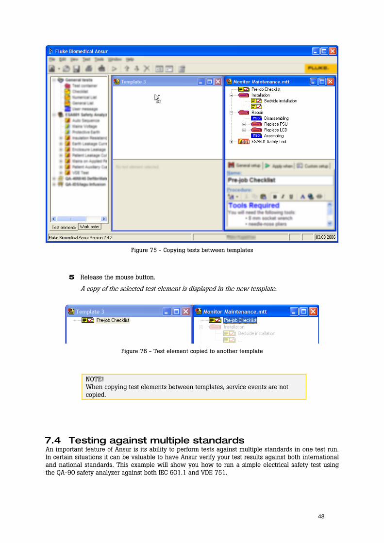
Figure 75 - Copying tests between templates
5 Release the mouse button.
A copy of the selected test element is displayed in the new template.
Figure 76 - Test element copied to another template
NOTE! When copying test elements between templates, service events are not copied.
7.4 Testing against multiple standards An important feature of Ansur is its ability to perform tests against multiple standards in one test run. In certain situations it can be valuable to have Ansur verify your test results against both international and national standards. This example will show you how to run a simple electrical safety test using the QA-90 safety analyzer against both IEC 601.1 and VDE 751.

49
NOTE! The example shown here is not a complete IEC or VDE test, it just illustrates how to create a template to test against multiple standards in one test run.
In order to use safety tests for the QA-90 instrument you must have the QA-90 plug-in installed.
If you have only Ansur installed, the only standard listed will be Ansur – User Defined. If you have installed certain additional plug-ins, such as the QA-90 plug-in, several additional standards will be listed.
Create a new template 1 Create a new test template and add the required safety tests. We’ll place all safety tests in
a QA-90 Test Sequence so that they are performed automatically. See the QA-90 plug-in’s user manual for more information on automatic test sequences.
Safety tests are displayed in the template.
Figure 77 - Safety test template
Select the standards 2 Select the QA-90 Test Sequence test element and click Apply when in the test element
setup. You may also press F6 on the keyboard.
The Apply when page is displayed.
3 In the list named Apply when performing, select the standards against which you want to enter limits. In this example we’ll tick off IEC 601.1 and VDE-751.
A checkbox is shown next to the selected standards.
Figure 78 - Selecting standards
NOTE! The tests from the QA-90 plug-in will have limits assigned to the IEC 601.1 and VDE 751 standards. This is not the case for all tests and all standards. See the plug-in’s user manual for information on the tests that have limits assigned.
50
Perform the safety tests 4 Click Test Start Test or click the Start Test button on the main toolbar.
You can also click F9 on the keyboard.
Figure 79 - Starting a test template
The Test Guide window for the QA-90 test sequence is now displayed.
5 Connect the QA-90. Define modules and calibrate the test leads if needed.
See the QA-90 plug-in’s user manual for more information on preparing for a QA-90 safety test.
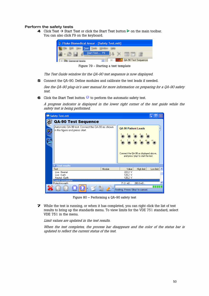
6 Click the Start Test button to perform the automatic safety test.
A progress indicator is displayed in the lower right corner of the test guide while the safety test is being performed.
Figure 80 – Performing a QA-90 safety test
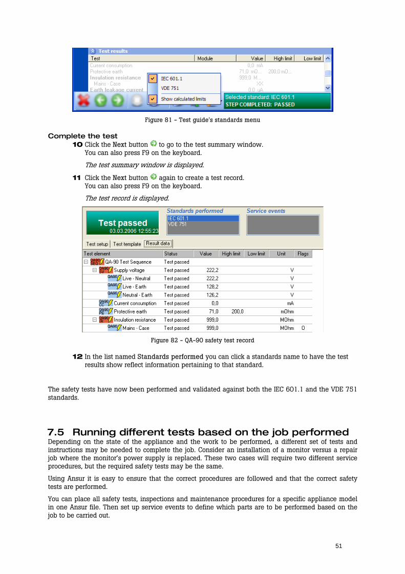
7 While the test is running, or when it has completed, you can right click the list of test results to bring up the standards menu. To view limits for the VDE 751 standard, select VDE 751 in the menu.
Limit values are updated in the test results.
When the test completes, the process bar disappears and the color of the status bar is updated to reflect the current status of the test.
51
Figure 81 - Test guide's standards menu
Complete the test 10 Click the Next button to go to the test summary window.
You can also press F9 on the keyboard.
The test summary window is displayed.
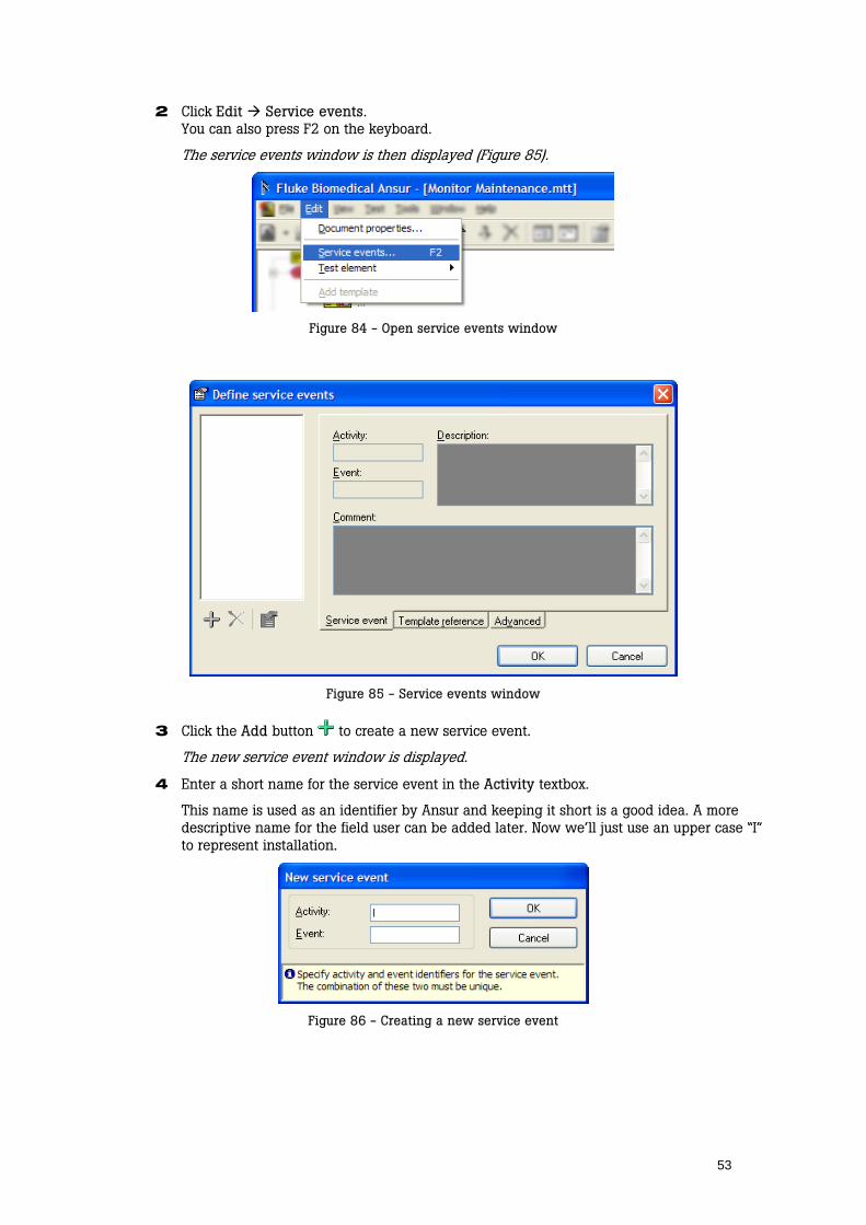
11 Click the Next button again to create a test record. You can also press F9 on the keyboard.
The test record is displayed.
Figure 82 - QA-90 safety test record
12 In the list named Standards performed you can click a standards name to have the test results show reflect information pertaining to that standard.
The safety tests have now been performed and validated against both the IEC 601.1 and the VDE 751 standards.
7.5 Running different tests based on the job performed Depending on the state of the appliance and the work to be performed, a different set of tests and instructions may be needed to complete the job. Consider an installation of a monitor versus a repair job where the monitor’s power supply is replaced. These two cases will require two different service procedures, but the required safety tests may be the same.
Using Ansur it is easy to ensure that the correct procedures are followed and that the correct safety tests are performed.
You can place all safety tests, inspections and maintenance procedures for a specific appliance model in one Ansur file. Then set up service events to define which parts are to be performed based on the job to be carried out.

52
In this example we will create a template containing service procedures for both installation and repair, while the final safety test is the same for both activities. You will see how easy it is to create and maintain complete service procedures using Ansur.
NOTE! The template created here is not a complete test template for a medical monitor. It is only a simple example indicating how to handle different service events using the same test template.
Create the template First, create the template that is to be used for the two service events: installation and repair. The details of each test are not discussed as the focus is now on how to have Ansur run only the tests that apply to the selected service event.
1 Create a test template and add visual tests and safety tests to suit your needs for service procedures and safety testing. More information on creating and configuring test templates can be found in chapters 4 through 6.
The template created is now displayed in Ansur. Figure 83 illustrates an example of such a template. The Ansur explorer has been hidden on this figure.
Figure 83 - Sample template for monitor maintenance
The example template shown in Figure 83 contains three main test blocks: Installation, Repair and ESA601 Safety Test. These test blocks have been created by placing test elements within test containers (see section 6.3 on page 44).
We will now set up the template so that the Installation test block is only run when the field user performs an installation, and that the Repair test block is only run when a repair is carried out. We will ensure that Pre-job Checklist and ESA601 Safety Test always are run.
Define service events A service event defines one job or activity the template can be used to verify.
53
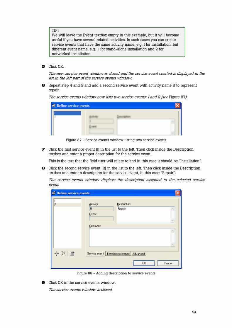
2 Click Edit Service events. You can also press F2 on the keyboard.
The service events window is then displayed (Figure 85).
Figure 84 - Open service events window
Figure 85 - Service events window
3 Click the Add button to create a new service event.
The new service event window is displayed.
4 Enter a short name for the service event in the Activity textbox.
This name is used as an identifier by Ansur and keeping it short is a good idea. A more descriptive name for the field user can be added later. Now we’ll just use an upper case “I” to represent installation.
Figure 86 - Creating a new service event
54
TIP! We will leave the Event textbox empty in this example, but it will become useful if you have several related activities. In such cases you can create service events that have the same activity name, e.g. I for installation, but different event name, e.g. 1 for stand-alone installation and 2 for networked installation.
5 Click OK.
The new service event window is closed and the service event created is displayed in the list in the left part of the service events window.
6 Repeat step 4 and 5 and add a second service event with activity name R to represent repair.
The service events window now lists two service events: I and R (see Figure 87).
Figure 87 - Service events window listing two service events
7 Click the first service event (I) in the list to the left. Then click inside the Description textbox and enter a proper description for the service event.
This is the text that the field user will relate to and in this case it should be “Installation”.
8 Click the second service event (R) in the list to the left. Then click inside the Description textbox and enter a description for the service event, in this case “Repair”.
The service events window displays the description assigned to the selected service event.
Figure 88 - Adding description to service events
9 Click OK in the service events window.
The service events window is closed.

55
Assign tests to the service events Your test template now defines two service events: Installation and Repair. The next step is to determine which tests are to be run for the different service events.
10 Click the test element named Installation shown in the template window on Figure 83. Then click the Apply when tab in the test element setup frame.
The Apply when page is displayed and the service events just created are listed in the frame named Service events.
11 Click the checkbox I: Installation displayed in the Service events list.
The checkbox now displays a red check mark (Figure 89). You have now told Ansur that this test block should only be run when the field user has selected the Installation service event.
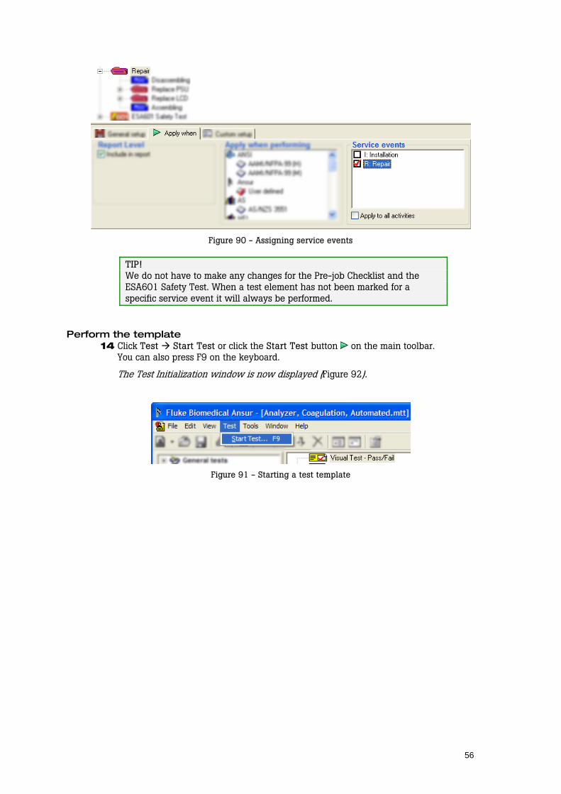
Figure 89 - Assigning service events
12 Click the test element named Repair shown in the template window on Figure 83.
The Apply when page is displayed and the service events just created are listed in the frame named Service events. None of the service events are checked off yet.
13 Click the checkbox R: Repair displayed in the Service events list.
The checkbox now displays a red check mark (Figure 90). You have now told Ansur that this test block should only be run when the field user has selected the Repair service event.
56
Figure 90 - Assigning service events
TIP! We do not have to make any changes for the Pre-job Checklist and the ESA601 Safety Test. When a test element has not been marked for a specific service event it will always be performed.
Perform the template 14 Click Test Start Test or click the Start Test button on the main toolbar.
You can also press F9 on the keyboard.
The Test Initialization window is now displayed (Figure 92).
Figure 91 - Starting a test template

57
Figure 92 - Selecting service events in the Test Initialization window
15 Select the service event that is to be performed and click the Next button to continue to the first test guide.
The Pre-job Checklist is displayed. When you complete this test and continue with the next you will see that the Installation and Repair tests are only included if you have selected the corresponding service event. The ESA601 Safety Test is always performed.
58
8 Working with Test Sequences
A test sequence is the combination of a test template and specific DUT information that you wish to associate with the test template. This information could include any information about the product being tested, specifics about the template itself, or the result data that is compiled after the test runs.
8.1 Creating a test sequence
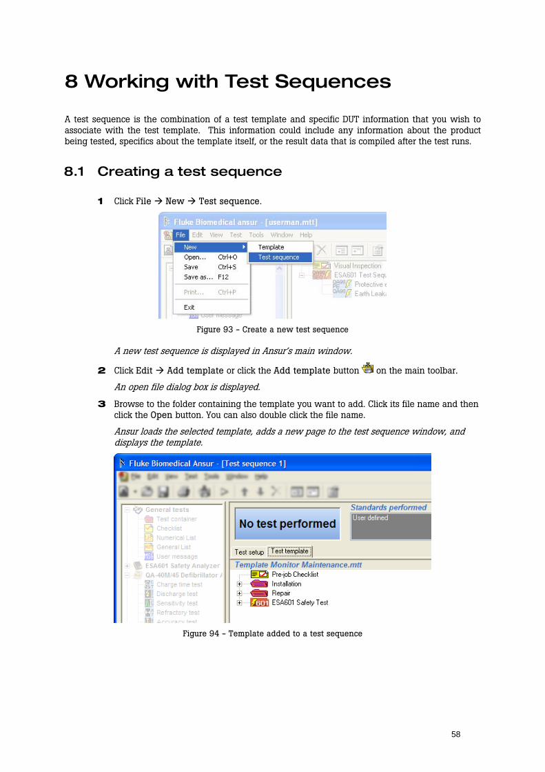
1 Click File New Test sequence.
Figure 93 - Create a new test sequence
A new test sequence is displayed in Ansur’s main window.
2 Click Edit Add template or click the Add template button on the main toolbar.
An open file dialog box is displayed.
3 Browse to the folder containing the template you want to add. Click its file name and then click the Open button. You can also double click the file name.
Ansur loads the selected template, adds a new page to the test sequence window, and displays the template.
Figure 94 - Template added to a test sequence
59
8.2 Editing DUT info
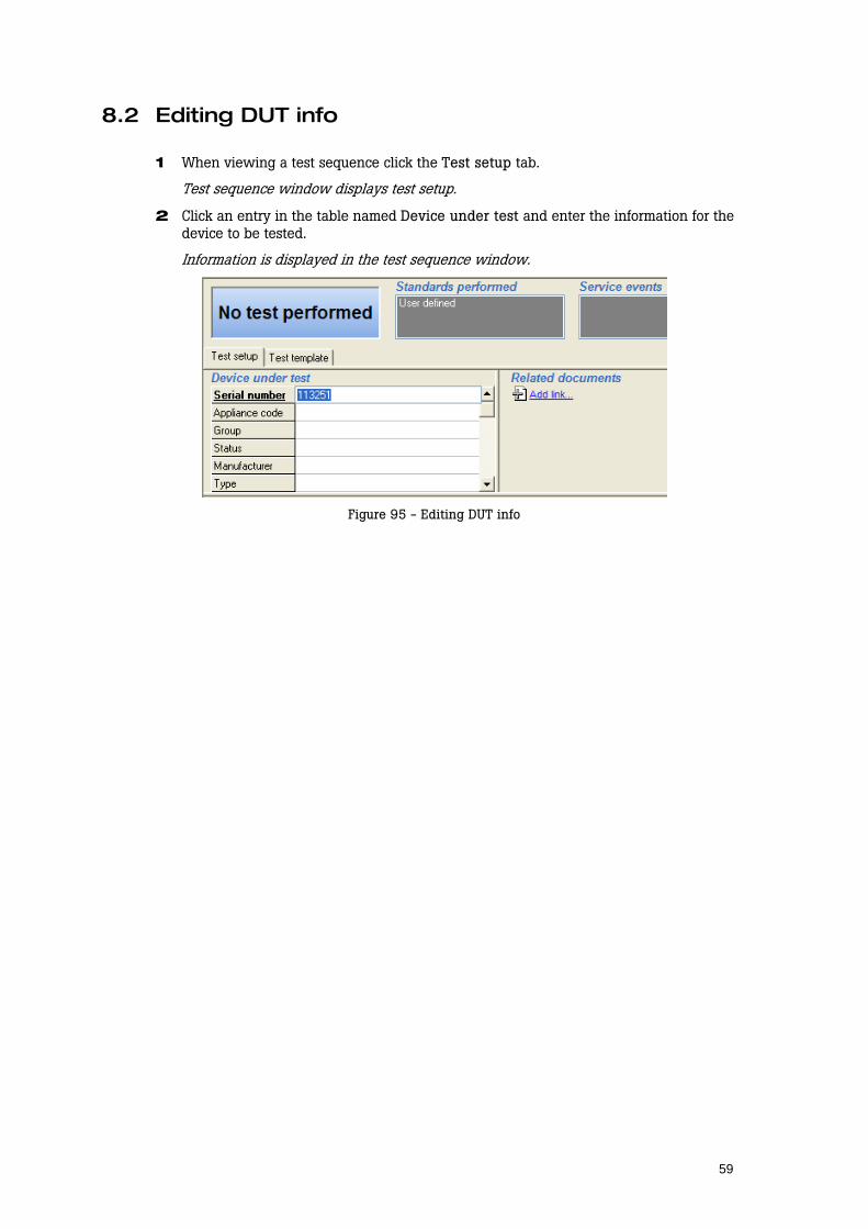
1 When viewing a test sequence click the Test setup tab.
Test sequence window displays test setup.
2 Click an entry in the table named Device under test and enter the information for the device to be tested.
Information is displayed in the test sequence window.
Figure 95 - Editing DUT info

60
9 Working with Test Records
Test records are the information that is compiled after the test template runs. It can consist of any data gathered while testing/inspecting a piece of equipment, the particular test template (and its properties) used to test the equipment and any information that was entered into the test sequence prior to the testing. While the information is available to view, copy or print, anything that was entered into the template or sequence prior to the test run, or information gathered during the test/inspection is not available to be manipulated in any way.
9.1 Determining a test’s status The test status displayed in the upper left corner of the test record window can display five different statuses, each giving you important information on the test performed.
All performed tests passed. The date and time indicates the point when the test was completed.
One or more tests failed.
All performed tests are flagged as not applicable.
The test was aborted by the field user and was not completed properly.
No test has been performed.
9.2 Viewing skipped tests You can filter the test results so that it only displays tests that failed or even tests that were skipped when the template was performed. By default Ansur will display only the tests that have been performed.
1 Right click the test results list to bring up the test results’ Display menu.
The display menu is shown.
Figure 96 - Test results' display menu
61
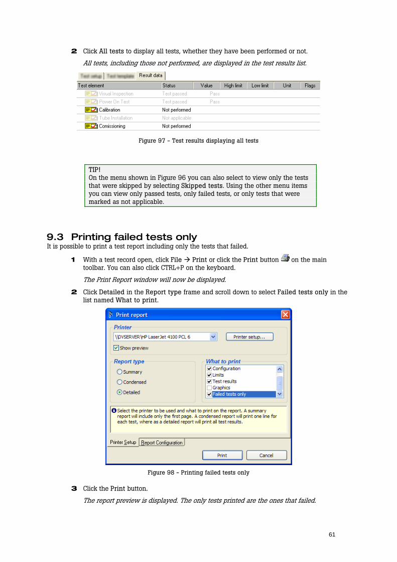
2 Click All tests to display all tests, whether they have been performed or not.
All tests, including those not performed, are displayed in the test results list.
Figure 97 - Test results displaying all tests
TIP! On the menu shown in Figure 96 you can also select to view only the tests that were skipped by selecting Skipped tests. Using the other menu items you can view only passed tests, only failed tests, or only tests that were marked as not applicable.
9.3 Printing failed tests only It is possible to print a test report including only the tests that failed.
1 With a test record open, click File Print or click the Print button on the main toolbar. You can also click CTRL+P on the keyboard.
The Print Report window will now be displayed.
2 Click Detailed in the Report type frame and scroll down to select Failed tests only in the list named What to print.
Figure 98 - Printing failed tests only
3 Click the Print button.
The report preview is displayed. The only tests printed are the ones that failed.
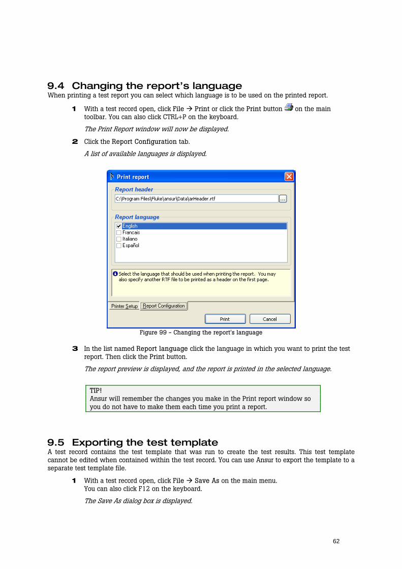
62
9.4 Changing the report’s language When printing a test report you can select which language is to be used on the printed report.
1 With a test record open, click File Print or click the Print button on the main toolbar. You can also click CTRL+P on the keyboard.
The Print Report window will now be displayed.
2 Click the Report Configuration tab.
A list of available languages is displayed.
Figure 99 - Changing the report's language
3 In the list named Report language click the language in which you want to print the test report. Then click the Print button.
The report preview is displayed, and the report is printed in the selected language.
TIP! Ansur will remember the changes you make in the Print report window so you do not have to make them each time you print a report.
9.5 Exporting the test template A test record contains the test template that was run to create the test results. This test template cannot be edited when contained within the test record. You can use Ansur to export the template to a separate test template file.
1 With a test record open, click File Save As on the main menu. You can also click F12 on the keyboard.
The Save As dialog box is displayed.
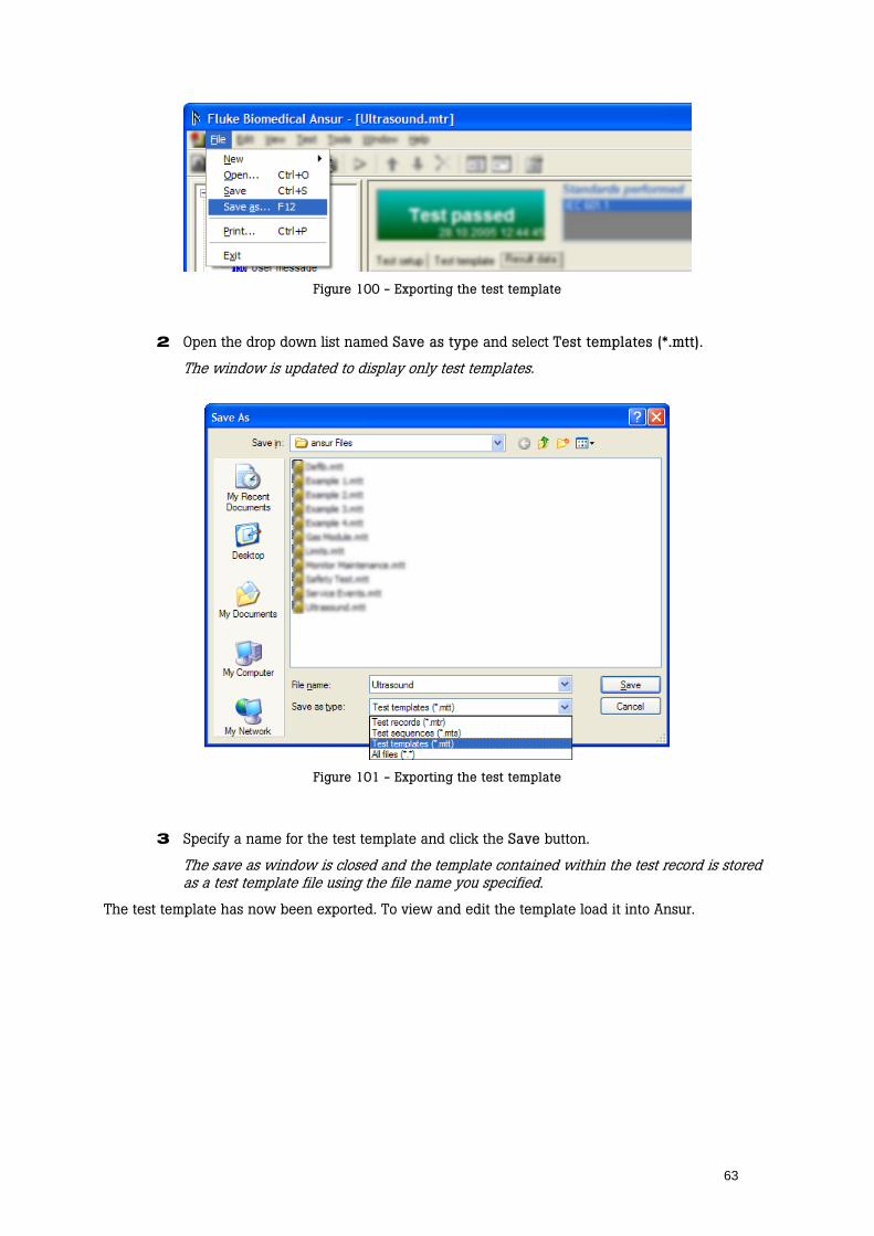
63
Figure 100 - Exporting the test template
2 Open the drop down list named Save as type and select Test templates (*.mtt).
The window is updated to display only test templates.
Figure 101 - Exporting the test template
3 Specify a name for the test template and click the Save button.
The save as window is closed and the template contained within the test record is stored as a test template file using the file name you specified.
The test template has now been exported. To view and edit the template load it into Ansur.
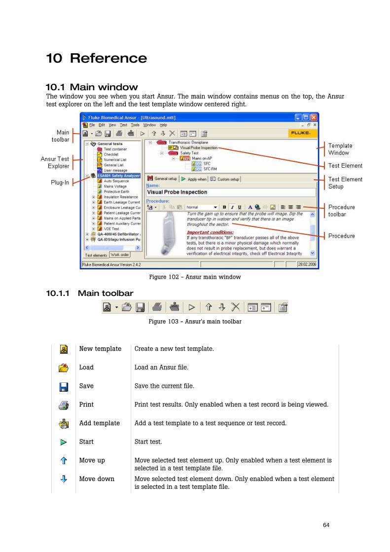
64
10 Reference
10.1 Main window The window you see when you start Ansur. The main window contains menus on the top, the Ansur test explorer on the left and the test template window centered right.
Figure 102 - Ansur main window
10.1.1 Main toolbar
Figure 103 - Ansur's main toolbar
New template Create a new test template.
Load Load an Ansur file.
Save Save the current file.
Print Print test results. Only enabled when a test record is being viewed.
Add template Add a test template to a test sequence or test record.
Start Start test.
Move up Move selected test element up. Only enabled when a test element is selected in a test template file.
Move down Move selected test element down. Only enabled when a test element is selected in a test template file.
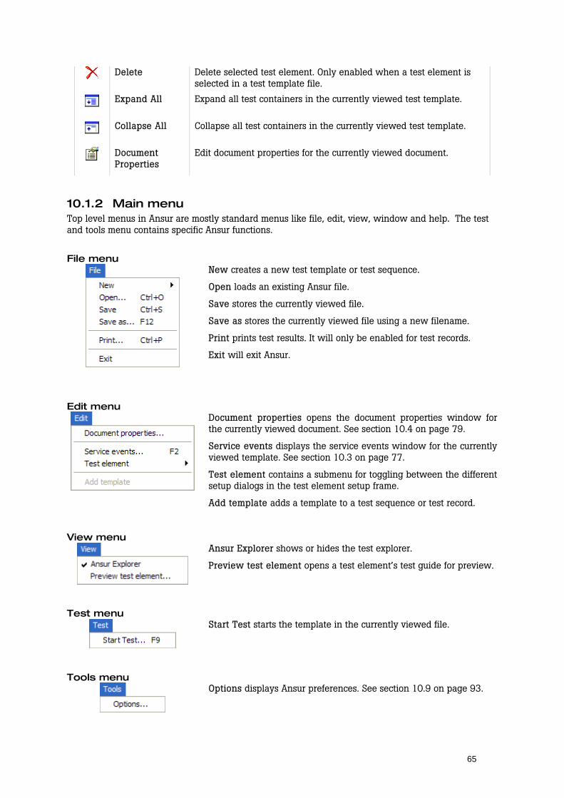
65
Delete Delete selected test element. Only enabled when a test element is selected in a test template file.
Expand All Expand all test containers in the currently viewed test template.
Collapse All Collapse all test containers in the currently viewed test template.
Document Properties
Edit document properties for the currently viewed document.
10.1.2 Main menu Top level menus in Ansur are mostly standard menus like file, edit, view, window and help. The test and tools menu contains specific Ansur functions.
File menu
New creates a new test template or test sequence.
Open loads an existing Ansur file.
Save stores the currently viewed file.
Save as stores the currently viewed file using a new filename.
Print prints test results. It will only be enabled for test records.
Exit will exit Ansur.
Edit menu
Document properties opens the document properties window for the currently viewed document. See section 10.4 on page 79.
Service events displays the service events window for the currently viewed template. See section 10.3 on page 77.
Test element contains a submenu for toggling between the different setup dialogs in the test element setup frame.
Add template adds a template to a test sequence or test record.
View menu
Ansur Explorer shows or hides the test explorer.
Preview test element opens a test element’s test guide for preview.
Test menu
Start Test starts the template in the currently viewed file.
Tools menu
Options displays Ansur preferences. See section 10.9 on page 93.
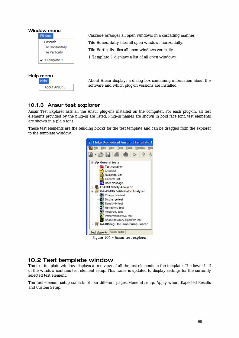
66
Window menu
Cascade arranges all open windows in a cascading manner.
Tile Horizontally tiles all open windows horizontally.
Tile Vertically tiles all open windows vertically.
1 Template 1 displays a list of all open windows.
Help menu
About Ansur displays a dialog box containing information about the software and which plug-in versions are installed.
10.1.3 Ansur test explorer Ansur Test Explorer lists all the Ansur plug-ins installed on the computer. For each plug-in, all test elements provided by the plug-in are listed. Plug-in names are shown in bold face font, test elements are shown in a plain font.
These test elements are the building blocks for the test template and can be dragged from the explorer to the template window.
Figure 104 - Ansur test explorer
10.2 Test template window The test template window displays a tree view of all the test elements in the template. The lower half of the window contains test element setup. This frame is updated to display settings for the currently selected test element.
The test element setup consists of four different pages: General setup, Apply when, Expected Results and Custom Setup.
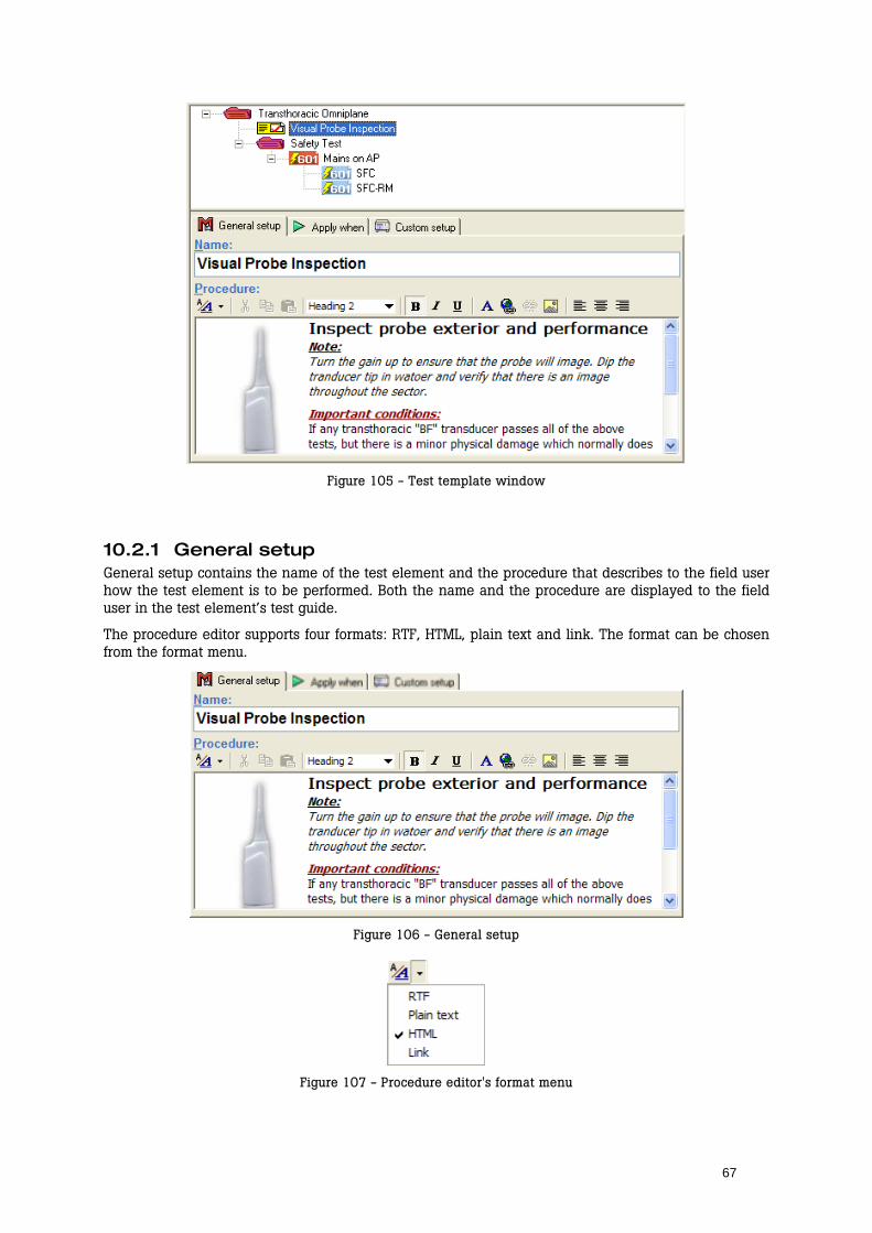
67
Figure 105 - Test template window
10.2.1 General setup General setup contains the name of the test element and the procedure that describes to the field user how the test element is to be performed. Both the name and the procedure are displayed to the field user in the test element’s test guide.
The procedure editor supports four formats: RTF, HTML, plain text and link. The format can be chosen from the format menu.
Figure 106 - General setup
Figure 107 - Procedure editor's format menu
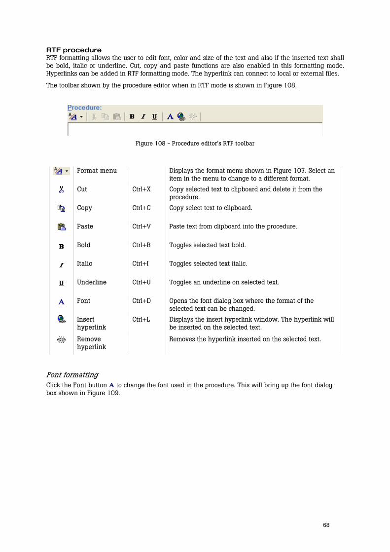
68
RTF procedure RTF formatting allows the user to edit font, color and size of the text and also if the inserted text shall be bold, italic or underline. Cut, copy and paste functions are also enabled in this formatting mode. Hyperlinks can be added in RTF formatting mode. The hyperlink can connect to local or external files.
The toolbar shown by the procedure editor when in RTF mode is shown in Figure 108.
Figure 108 - Procedure editor's RTF toolbar
Format menu Displays the format menu shown in Figure 107. Select an item in the menu to change to a different format.
Cut Ctrl+X Copy selected text to clipboard and delete it from the procedure.
Copy Ctrl+C Copy select text to clipboard.
Paste Ctrl+V Paste text from clipboard into the procedure.
Bold Ctrl+B Toggles selected text bold.
Italic Ctrl+I Toggles selected text italic.
Underline Ctrl+U Toggles an underline on selected text.
Font Ctrl+D Opens the font dialog box where the format of the selected text can be changed.
Insert hyperlink
Ctrl+L Displays the insert hyperlink window. The hyperlink will be inserted on the selected text.
Remove hyperlink
Removes the hyperlink inserted on the selected text.
Font formatting Click the Font button to change the font used in the procedure. This will bring up the font dialog box shown in Figure 109.
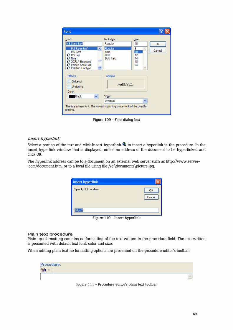
69
Figure 109 - Font dialog box
Insert hyperlink Select a portion of the text and click Insert hyperlink to insert a hyperlink in the procedure. In the insert hyperlink window that is displayed, enter the address of the document to be hyperlinked and click OK.
The hyperlink address can be to a document on an external web server such as http://www.server-.com/document.htm, or to a local file using file://c:\documents\picture.jpg.
Figure 110 - Insert hyperlink
Plain text procedure Plain text formatting contains no formatting of the text written in the procedure field. The text written is presented with default text font, color and size.
When editing plain text no formatting options are presented on the procedure editor’s toolbar.
Figure 111 - Procedure editor's plain text toolbar

70
HTML procedure HTML formatting provides all the same formatting features as RTF, and in addition the option to insert pictures into the procedure field. The text and pictures can also be justified right, left or center in the HTML formatting mode.
Figure 112 - Procedure editor's HTML toolbar
Format menu Displays the format menu shown in Figure 107. Select an item in the menu to change to a different format.
Cut Ctrl+X Copy selected text to clipboard and delete it from the procedure.
Copy Ctrl+C Copy select text to clipboard.
Paste Ctrl+V Paste text from clipboard into the procedure.
Style Select a style to be applied to the selected text. The available styles are Normal, Heading 1, Heading 2 and Heading 3. These styles are defined in the cascading style sheet referenced by Ansur preferences (see section 10.9)
Bold Ctrl+B Toggles selected text bold.
Italic Ctrl+I Toggles selected text italic.
Underline Ctrl+U Toggles an underline on selected text.
Font Ctrl+D Opens the font dialog box where the format of the selected text can be changed.
Insert hyperlink
Ctrl+L Displays the insert hyperlink window. The hyperlink will be inserted on the selected text.
Remove hyperlink
Removes the hyperlink inserted on the selected text.
Insert picture Insert a picture at the location of the cursor.
Align left Align selected paragraph left.
Align center Align selected paragraph center.
Align right Align selected paragraph right.
Font formatting Click the Font button to change the font used in the procedure. This will bring up the font dialog box shown below.
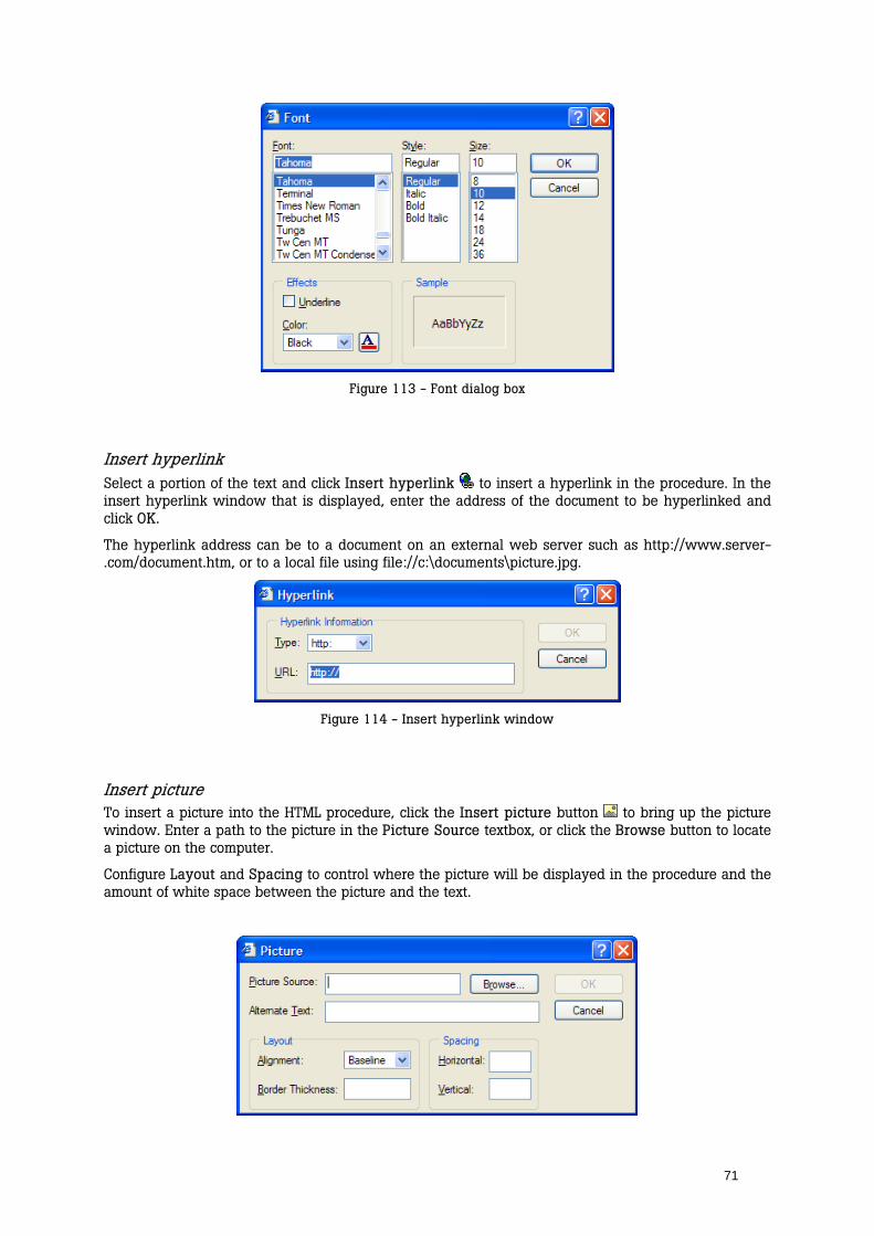
71
Figure 113 - Font dialog box
Insert hyperlink Select a portion of the text and click Insert hyperlink to insert a hyperlink in the procedure. In the insert hyperlink window that is displayed, enter the address of the document to be hyperlinked and click OK.
The hyperlink address can be to a document on an external web server such as http://www.server-.com/document.htm, or to a local file using file://c:\documents\picture.jpg.
Figure 114 - Insert hyperlink window
Insert picture To insert a picture into the HTML procedure, click the Insert picture button to bring up the picture window. Enter a path to the picture in the Picture Source textbox, or click the Browse button to locate a picture on the computer.
Configure Layout and Spacing to control where the picture will be displayed in the procedure and the amount of white space between the picture and the text.
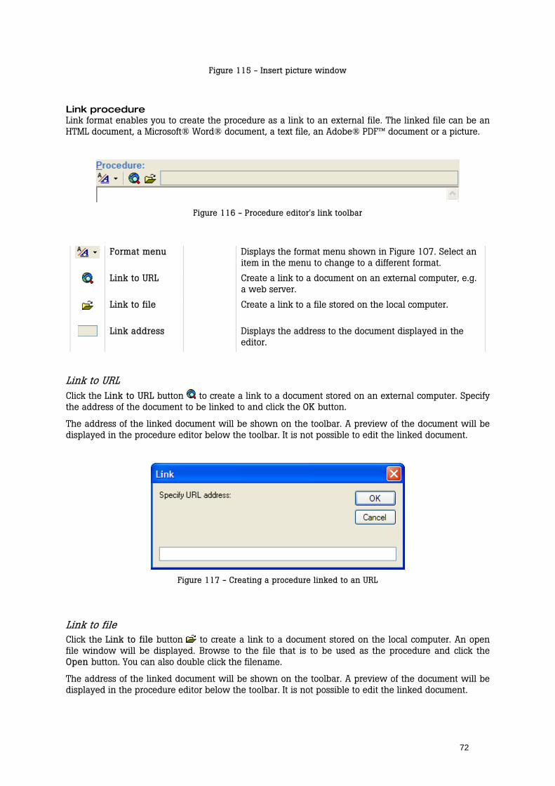
72
Figure 115 - Insert picture window
Link procedure Link format enables you to create the procedure as a link to an external file. The linked file can be an HTML document, a Microsoft® Word® document, a text file, an Adobe® PDF™ document or a picture.
Figure 116 - Procedure editor's link toolbar
Format menu Displays the format menu shown in Figure 107. Select an item in the menu to change to a different format.
Link to URL Create a link to a document on an external computer, e.g. a web server.
Link to file Create a link to a file stored on the local computer.
Link address Displays the address to the document displayed in the editor.
Link to URL Click the Link to URL button to create a link to a document stored on an external computer. Specify the address of the document to be linked to and click the OK button.
The address of the linked document will be shown on the toolbar. A preview of the document will be displayed in the procedure editor below the toolbar. It is not possible to edit the linked document.
Figure 117 - Creating a procedure linked to an URL
Link to file Click the Link to file button to create a link to a document stored on the local computer. An open file window will be displayed. Browse to the file that is to be used as the procedure and click the Open button. You can also double click the filename.
The address of the linked document will be shown on the toolbar. A preview of the document will be displayed in the procedure editor below the toolbar. It is not possible to edit the linked document.

73
Figure 118 - Creating a procedure linked to a file
10.2.2 Apply when The test element setup page named Apply when controls when the test is performed. It also allows you to specify the standards that can have limits assigned, as well as whether the test should show up on the printed report.
Figure 119 - Apply when
Report level Include in report specifies whether the test should be shown on the printed report. Uncheck this to remove the test from the printed report.
Apply when performing The list displays all standards available to Ansur. For a default Ansur installation without any additional plug-ins, only the User defined standard will be listed. See also Appendix F. Adding Standards on page 105 for information on how to add custom standards.
The standards selected will also be displayed on the Expected results page where limits can be assigned.
NOTE! If the test element is placed within a container, the list will only display the standards selected on the container. If no standard is selected on the container all available standards will be listed.

74
Service events The service events list shows all activities defined in the template. A service event defines the type of activity for which the test element is applicable (i.e. if it should be executed for PM, certain types of repair activities, etc). See section 10.3 on page 77 for more information on service events.
If one or several service events are checked, then the test element will be performed if at least one of the selected events also is selected in the Test Initialization window (Figure 135) when the template is performed.
For activities containing several events (e.g. I1 and I2 on Figure 119) it is possible to check mark the overall activity to have the test element execute for all events in this activity.
The test element will always be performed if no service events are selected.
NOTE! If the test element is placed within a container, the list will only display the service events selected on the container. If no service event is selected on the container all service events defined in the template will be listed.
10.2.3 Expected results The test element setup page named Expected results displays a table that lists every measurement taken by the test for each standard selected in Apply when. A maximum (high) and minimum (low) legal value can be assigned.
Figure 120 - Expected results
There are three types of limits that can be used in Ansur:
Absolute limits where the value entered will be the limit applied to the test.
Dynamic limits where the value entered will be added to or subtracted from a given predefined value. This is used with tests where the DUT should provide a known value, e.g. a defibrillator discharge test. Dynamic limits will be indicated by this icon next to the limit’s name.
Relative limits will retrieve a value from another Ansur test and use it to calculate the limit value to be applied. Relative limits will be indicated by this icon next to the limit’s name.
Dynamic limits Dynamic limits are supported by several test elements in some of the additional plug-ins, (e.g. the charge time test found in the QA-45 plug-in and the flow test found in the lagu plug-in.)
The value entered in expected results for a dynamic limit will be used in a calculation together with a predefined value for the measurement to create the final value against which the measurement will be compared.
The energy limits displayed in Figure 121 will be calculated as ±10% of a preset energy level that is entered in the test element’s custom setup. Hence a preset energy of 360J will be tested against the limits 396J and 324J.
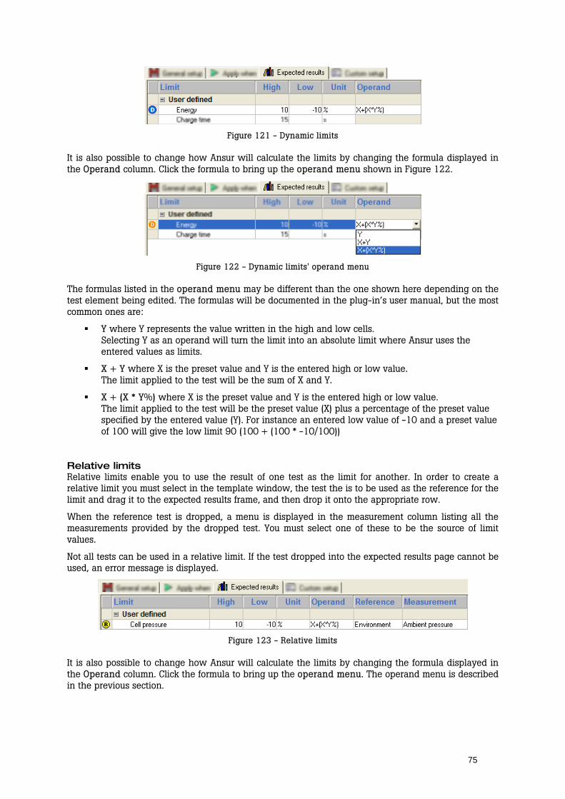
75
Figure 121 - Dynamic limits
It is also possible to change how Ansur will calculate the limits by changing the formula displayed in the Operand column. Click the formula to bring up the operand menu shown in Figure 122.
Figure 122 - Dynamic limits' operand menu
The formulas listed in the operand menu may be different than the one shown here depending on the test element being edited. The formulas will be documented in the plug-in’s user manual, but the most common ones are:
Y where Y represents the value written in the high and low cells. Selecting Y as an operand will turn the limit into an absolute limit where Ansur uses the entered values as limits.
X + Y where X is the preset value and Y is the entered high or low value. The limit applied to the test will be the sum of X and Y.
X + (X * Y%) where X is the preset value and Y is the entered high or low value. The limit applied to the test will be the preset value (X) plus a percentage of the preset value specified by the entered value (Y). For instance an entered low value of -10 and a preset value of 100 will give the low limit 90 (100 + (100 * -10/100))
Relative limits Relative limits enable you to use the result of one test as the limit for another. In order to create a relative limit you must select in the template window, the test the is to be used as the reference for the limit and drag it to the expected results frame, and then drop it onto the appropriate row.
When the reference test is dropped, a menu is displayed in the measurement column listing all the measurements provided by the dropped test. You must select one of these to be the source of limit values.
Not all tests can be used in a relative limit. If the test dropped into the expected results page cannot be used, an error message is displayed.
Figure 123 - Relative limits
It is also possible to change how Ansur will calculate the limits by changing the formula displayed in the Operand column. Click the formula to bring up the operand menu. The operand menu is described in the previous section.
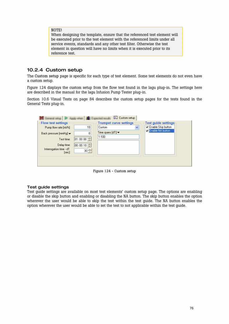
76
NOTE! When designing the template, ensure that the referenced test element will be executed prior to the test element with the referenced limits under all service events, standards and any other test filter. Otherwise the test element in question will have no limits when it is executed prior to its reference test.
10.2.4 Custom setup The Custom setup page is specific for each type of test element. Some test elements do not even have a custom setup.
Figure 124 displays the custom setup from the flow test found in the lagu plug-in. The settings here are described in the manual for the lagu Infusion Pump Tester plug-in.
Section 10.6 Visual Tests on page 84 describes the custom setup pages for the tests found in the General Tests plug-in.
Figure 124 - Custom setup
Test guide settings Test guide settings are available on most test elements’ custom setup page. The options are enabling or disable the skip button and enabling or disabling the NA button. The skip button enables the option wherever the user would be able to skip the test within the test guide. The NA button enables the option wherever the user would be able to set the test to not applicable within the test guide.
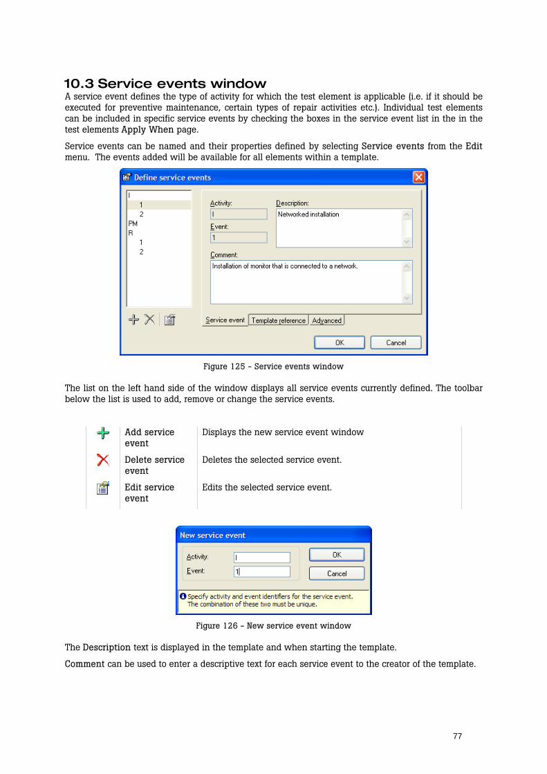
77
10.3 Service events window A service event defines the type of activity for which the test element is applicable (i.e. if it should be executed for preventive maintenance, certain types of repair activities etc.). Individual test elements can be included in specific service events by checking the boxes in the service event list in the in the test elements Apply When page.
Service events can be named and their properties defined by selecting Service events from the Edit menu. The events added will be available for all elements within a template.
Figure 125 - Service events window
The list on the left hand side of the window displays all service events currently defined. The toolbar below the list is used to add, remove or change the service events.
Add service event
Displays the new service event window
Delete service event
Deletes the selected service event.
Edit service event
Edits the selected service event.
Figure 126 - New service event window
The Description text is displayed in the template and when starting the template.
Comment can be used to enter a descriptive text for each service event to the creator of the template.

78
TIP! See section 10.5.1 on page 83 for information on how the field user selects the service events when starting the template.
Template reference Template references create references to another template. This feature is reserved for database integration.
Advanced Each group of service events (i.e. Activity) can be assigned a level. When a test is to be performed it must correspond to a selected service event on each level to which it has been assigned. This allows us to include different tests depending on the DUT model or tools and test instruments available.
Common examples when service event levels are handy are situations where the field engineers use different Fluke instruments to perform service on the same type of DUT. The regular service events will still be Installation, Repair, Preventive Maintenance and so on, but the field engineer must also be able to select the test instrument to be used.
To create service events on a different level, add a new group of activities using the Define service events window. Click the Advanced tab and increase the Level field. When changing the Level field for one service event, all events within the same activity will be assigned the same level.
Figure 127 - Advanced service event settings
Assign service events as usual, but for instrument specific tests, assign the proper Test Instrument event. The picture below has two test containers with safety tests. One with ESA601 safety tests, the other with QA-90 safety tests.
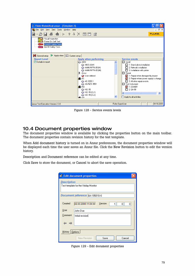
79
Figure 128 - Service events levels
10.4 Document properties window The document properties window is available by clicking the properties button on the main toolbar. The document properties contain revision history for the test template.
When Add document history is turned on in Ansur preferences, the document properties window will be displayed each time the user saves an Ansur file. Click the New Revision button to edit the version history.
Description and Document reference can be edited at any time.
Click Save to store the document, or Cancel to abort the save operation.
Figure 129 - Edit document properties
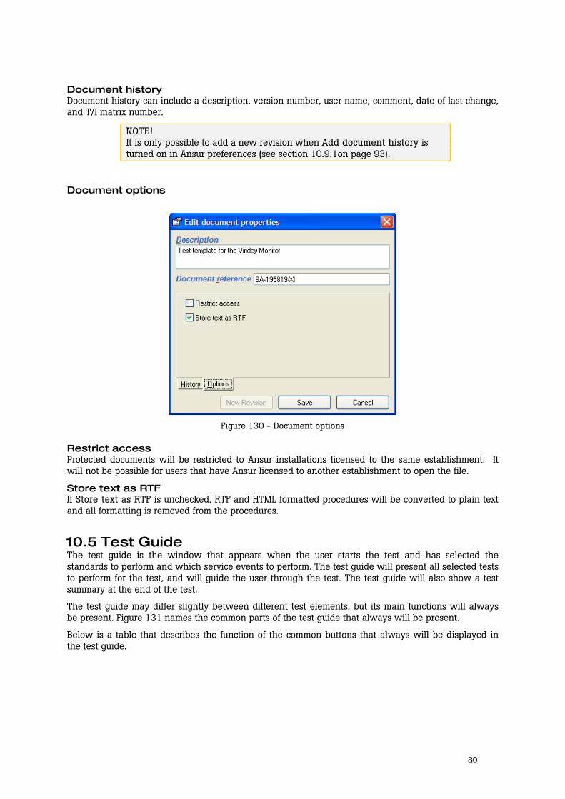
80
Document history Document history can include a description, version number, user name, comment, date of last change, and T/I matrix number.
NOTE! It is only possible to add a new revision when Add document history is turned on in Ansur preferences (see section 10.9.1on page 93).
Document options
Figure 130 - Document options
Restrict access Protected documents will be restricted to Ansur installations licensed to the same establishment. It will not be possible for users that have Ansur licensed to another establishment to open the file.
Store text as RTF If Store text as RTF is unchecked, RTF and HTML formatted procedures will be converted to plain text and all formatting is removed from the procedures.
10.5 Test Guide The test guide is the window that appears when the user starts the test and has selected the standards to perform and which service events to perform. The test guide will present all selected tests to perform for the test, and will guide the user through the test. The test guide will also show a test summary at the end of the test.
The test guide may differ slightly between different test elements, but its main functions will always be present. Figure 131 names the common parts of the test guide that always will be present.
Below is a table that describes the function of the common buttons that always will be displayed in the test guide.
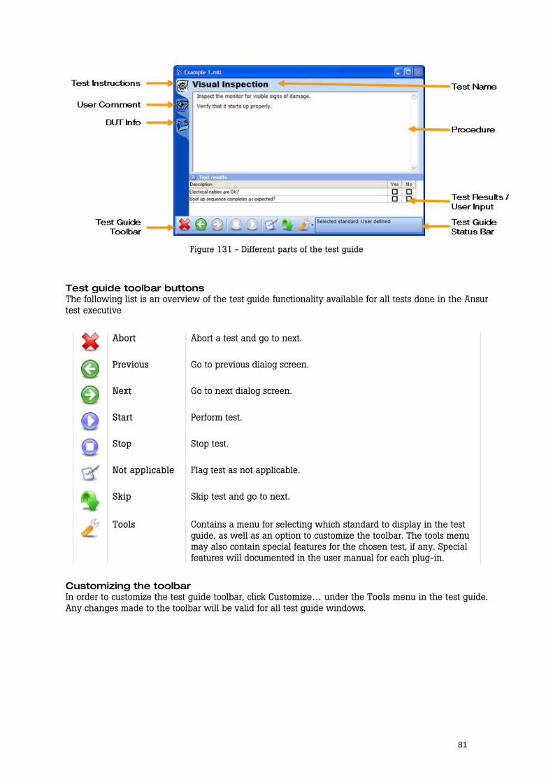
81
Figure 131 - Different parts of the test guide
Test guide toolbar buttons The following list is an overview of the test guide functionality available for all tests done in the Ansur test executive
Abort Abort a test and go to next.
Previous Go to previous dialog screen.
Next Go to next dialog screen.
Start Perform test.
Stop Stop test.
Not applicable Flag test as not applicable.
Skip Skip test and go to next.
Tools Contains a menu for selecting which standard to display in the test
guide, as well as an option to customize the toolbar. The tools menu may also contain special features for the chosen test, if any. Special features will documented in the user manual for each plug-in.
Customizing the toolbar In order to customize the test guide toolbar, click Customize… under the Tools menu in the test guide. Any changes made to the toolbar will be valid for all test guide windows.
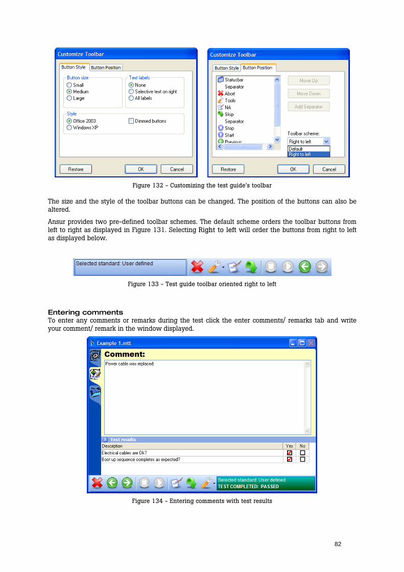
82
Figure 132 - Customizing the test guide's toolbar
The size and the style of the toolbar buttons can be changed. The position of the buttons can also be altered.
Ansur provides two pre-defined toolbar schemes. The default scheme orders the toolbar buttons from left to right as displayed in Figure 131. Selecting Right to left will order the buttons from right to left as displayed below.
Figure 133 - Test guide toolbar oriented right to left
Entering comments To enter any comments or remarks during the test click the enter comments/ remarks tab and write your comment/ remark in the window displayed.
Figure 134 - Entering comments with test results
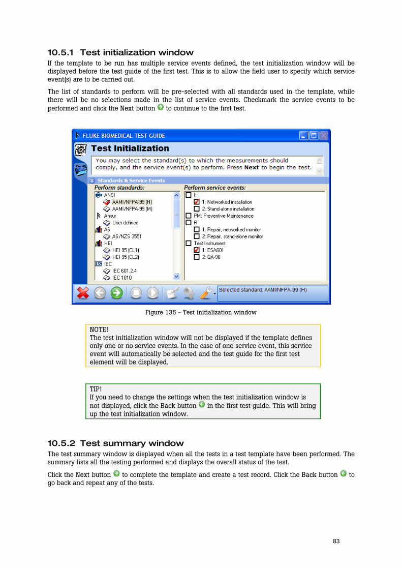
83
10.5.1 Test initialization window If the template to be run has multiple service events defined, the test initialization window will be displayed before the test guide of the first test. This is to allow the field user to specify which service event(s) are to be carried out.
The list of standards to perform will be pre-selected with all standards used in the template, while there will be no selections made in the list of service events. Checkmark the service events to be performed and click the Next button to continue to the first test.
Figure 135 - Test initialization window
NOTE! The test initialization window will not be displayed if the template defines only one or no service events. In the case of one service event, this service event will automatically be selected and the test guide for the first test element will be displayed.
TIP! If you need to change the settings when the test initialization window is not displayed, click the Back button in the first test guide. This will bring up the test initialization window.
10.5.2 Test summary window The test summary window is displayed when all the tests in a test template have been performed. The summary lists all the testing performed and displays the overall status of the test.
Click the Next button to complete the template and create a test record. Click the Back button to go back and repeat any of the tests.

84
Figure 136 - Test summary window
10.6 Visual Tests The tests found under the heading General tests are included in the basic Ansur test executive and are referred to as visual tests.
The tests provided by the visual plug-in are a test container, checklist, numerical list, general list and user message.
This section will present the details on these test elements.
10.6.1 Test Container The test container is a container that can hold various combinations of test elements decided upon by the user. The elements are selected and designed for the specific application and placed within the test container. The test container is general, and is normally used for structuring/grouping your test so the template is more manageable when you edit it.
Conditional test containers A test container can also be used to include tests only when a certain condition is met. For example, an electrical safety test may only need to be performed if there are signs of damage that may compromise the safety of the equipment.
To create a conditional test add a Test Container and go to the Custom setup window. In the second drop down menu select the test which condition is to be tested. To test an individual step, select it in the third drop down menu. In the fourth and fifth drop down menu, select the comparison to be made and the valid outcome. Then click the Add to list button.
When adding several conditions to the same test container, the first drop down menu selects the logic that will be used to test whether or not to perform the container. The available selections are:
and The container will be performed only if both the condition with the and-operator and the condition above evaluates to true.
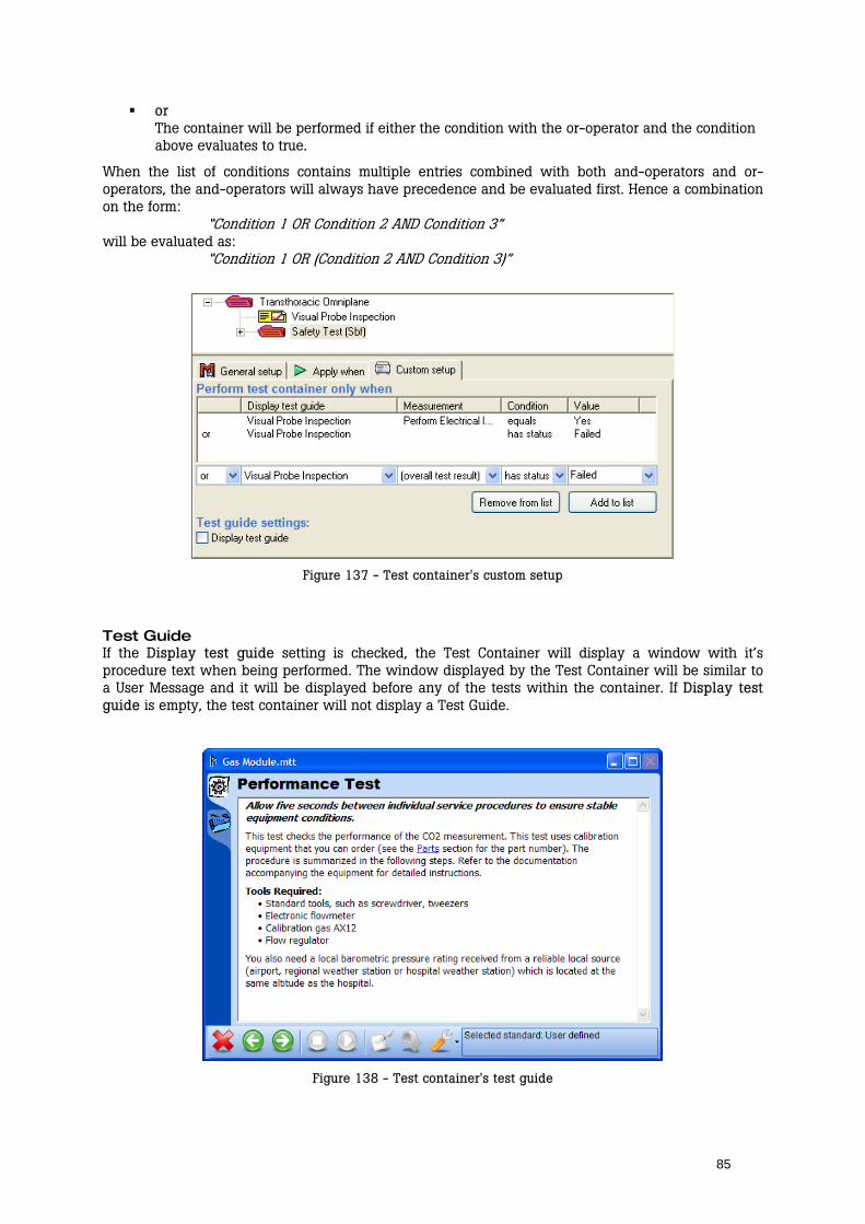
85
or The container will be performed if either the condition with the or-operator and the condition above evaluates to true.
When the list of conditions contains multiple entries combined with both and-operators and or-operators, the and-operators will always have precedence and be evaluated first. Hence a combination on the form:
“Condition 1 OR Condition 2 AND Condition 3” will be evaluated as:
“Condition 1 OR (Condition 2 AND Condition 3)”
Figure 137 - Test container's custom setup
Test Guide If the Display test guide setting is checked, the Test Container will display a window with it’s procedure text when being performed. The window displayed by the Test Container will be similar to a User Message and it will be displayed before any of the tests within the container. If Display test guide is empty, the test container will not display a Test Guide.
Figure 138 - Test container's test guide

86
10.6.2 Checklist A checklist is a test element that contains no quantifiable data. They are successful or unsuccessful based solely on what the user/operator can perceive without applying any kind of range to the test. The visual tests have a unique feature over automatic tests, there can be several instructions (list items) given to the user. This gives a checklist like facility available through the Custom Setup window of the selected visual test element.
Adding check items Click the + button to add new check items to a check list. Click a cell to edit an item’s description. Add a new column by clicking any of the option columns’ titles and click the + button. To change the name of the option, click the option column’s title and enter a new name.
Figure 139 - Checklist's custom setup
Cell status The text Pass or Fail in the cells next to the description determines the status that the test element will be given when the operator checks off an option when the test is being performed. To change the status for a given item, click the cell to be altered and select a new status from the pop up menu.
There are four possible values that a cell can have: Pass
If a cell has status pass the test will be given the status pass when the corresponding checkbox is clicked in the test guide.
Fail If a cell has status fail the test will be given status fail when the corresponding checkbox is clicked in the test guide. The failed item will always take precedence over any other items.
Not Applicable If the operator clicks a checkbox that has its status set to Not Applicable, the test will be flagged as Not Applicable. However, this status has the lowest precedence. Hence if there exists another selection that is pass or fail, the test will be set to pass or fail instead.
Ignored By setting the cell’s status to Ignored, no checkbox will be displayed in the Test Guide and this option becomes unavailable to the operator.
Required items Each list item added to a checklist will be required by default. A required item will require an answer before the operator is allowed to continue in the test template. Consequently, the operator must check off all required items before the next button is enabled in the test guide.
Items that are not required will be shown with an alert icon next to the description.
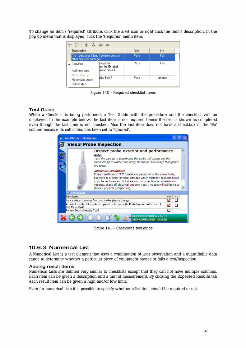
87
To change an item’s ‘required’ attribute, click the alert icon or right click the item’s description. In the pop up menu that is displayed, click the ‘Required’ menu item.
Figure 140 - Required checklist items
Test Guide When a Checklist is being performed, a Test Guide with the procedure and the checklist will be displayed. In the example below, the last item is not required hence the test is shown as completed even though the last item is not checked. Also the last item does not have a checkbox in the ‘No’ column because its cell status has been set to ‘Ignored’.
Figure 141 - Checklist's test guide
10.6.3 Numerical List A Numerical List is a test element that uses a combination of user observation and a quantifiable data range to determine whether a particular piece of equipment passes or fails a test/inspection.
Adding result items Numerical Lists are defined very similar to checklists except that they can not have multiple columns. Each item can be given a description and a unit of measurement. By clicking the Expected Results tab each result item can be given a high and/or low limit.
Even for numerical lists it is possible to specify whether a list item should be required or not.
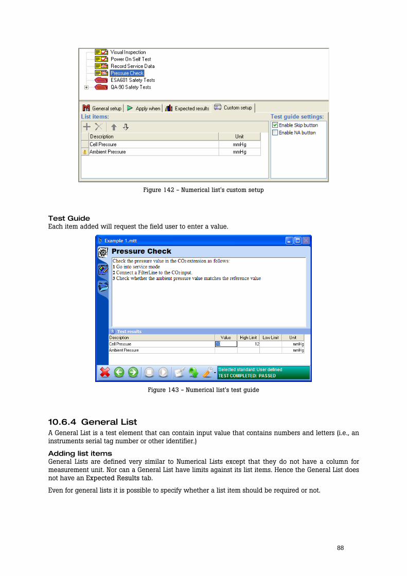
88
Figure 142 - Numerical list's custom setup
Test Guide Each item added will request the field user to enter a value.
Figure 143 - Numerical list's test guide
10.6.4 General List A General List is a test element that can contain input value that contains numbers and letters (i.e., an instruments serial tag number or other identifier.)
Adding list items General Lists are defined very similar to Numerical Lists except that they do not have a column for measurement unit. Nor can a General List have limits against its list items. Hence the General List does not have an Expected Results tab.
Even for general lists it is possible to specify whether a list item should be required or not.
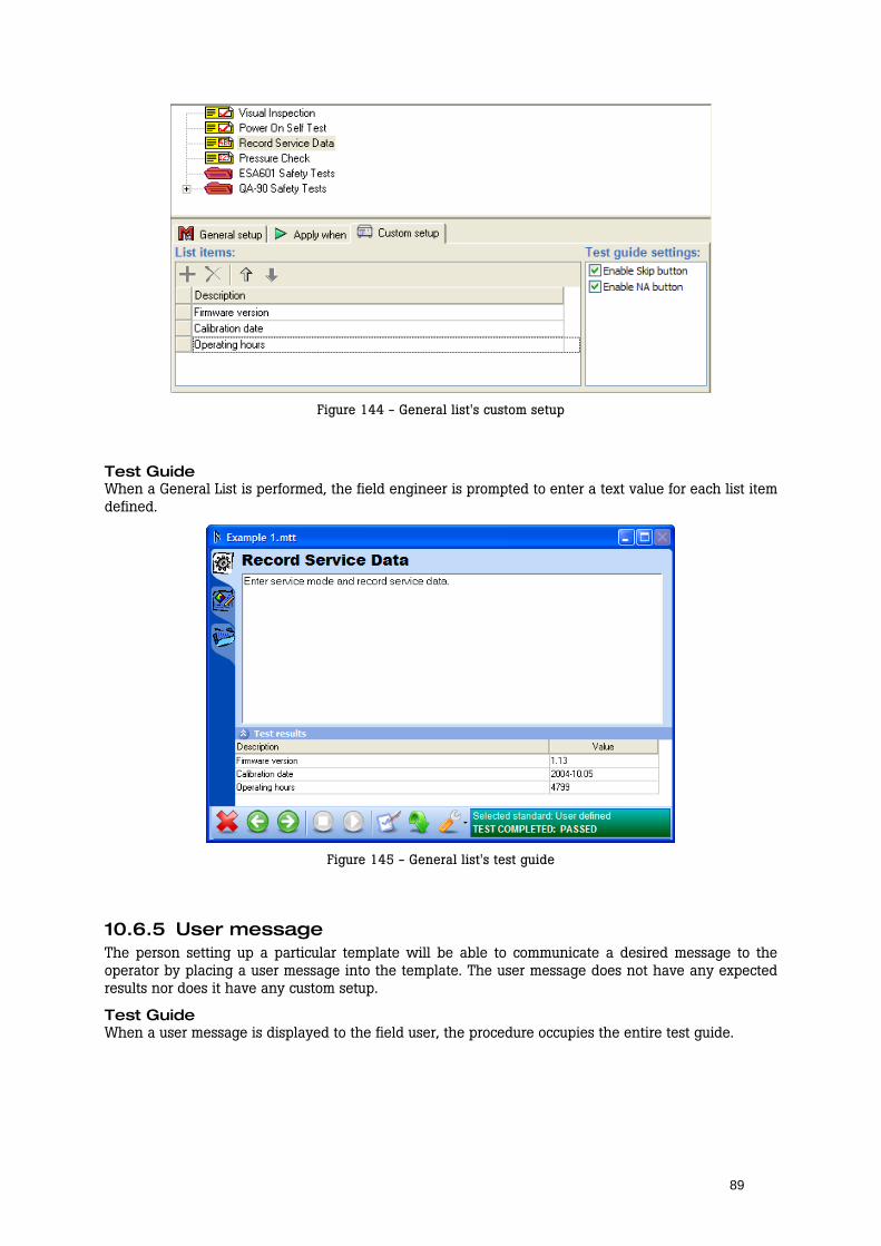
89
Figure 144 - General list's custom setup
Test Guide When a General List is performed, the field engineer is prompted to enter a text value for each list item defined.
Figure 145 - General list's test guide
10.6.5 User message The person setting up a particular template will be able to communicate a desired message to the operator by placing a user message into the template. The user message does not have any expected results nor does it have any custom setup.
Test Guide When a user message is displayed to the field user, the procedure occupies the entire test guide.
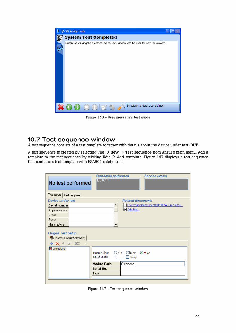
90
Figure 146 - User message's test guide
10.7 Test sequence window A test sequence consists of a test template together with details about the device under test (DUT).
A test sequence is created by selecting File New Test sequence from Ansur’s main menu. Add a template to the test sequence by clicking Edit Add template. Figure 147 displays a test sequence that contains a test template with ESA601 safety tests.
Figure 147 - Test sequence window

91
Device under test The table named Device under test contains information about the DUT. This information will be stored in the test sequence, as well as in the test record when the test sequence has been performed. The DUT information will also be shown on the printed report.
Figure 148 - DUT info on printed report
Plug-In Test Setup Plug-in Test Setup will only be used when tests used in the assigned test template requires additional information. Tests from the QA-90 and ESA601 plug-ins generally require additional information such as module setup in order to know how to perform safety tests. Documentation on how to use the features displayed in this frame is found in the corresponding plug-in’s user manual.
If no test in the assigned template requires additional test setup, this frame will be empty.
Related documents Related documents is an obsolete feature that is still present in Ansur in order to maintain backwards compatibility. In the related documents frame you can create links to other documents that are of importance for the test. However, we recommend that you rather use the new features for hyperlinks and linked test procedures available in the procedure editor.
See section 10.2.1 General setup on page 67 for more details on editing test procedures and creating links to other documents.
10.8 Test record window A test record consists of test setup, a test template and result data. Whenever a test template or a test sequence has been performed, a test record is created.
The test record window contains three pages accessible through tabs just below the status fields at the top of the window:
Test setup is the same as described in section 10.7 above.
Test template contains the template that has been run. The template cannot be edited in the test record window.
Result data displays the results of the test.
The status fields at the top of the test record window display the overall status of the test record as well as listing all standards and service events that have been performed.

92
Figure 149 - Test record window
Test Status The test status displayed in the upper left corner of the test record window can display five different statuses, each giving you important information on the test performed.
All performed tests passed. The date and time indicates the point when the test was completed.
One or more tests failed.
All performed tests are flagged as not applicable.
The test was aborted by the field user and was not completed properly.
No test has been performed.
Result data The result data can be filtered to display only passed or failed tests. Right click the result view to open the display menu.
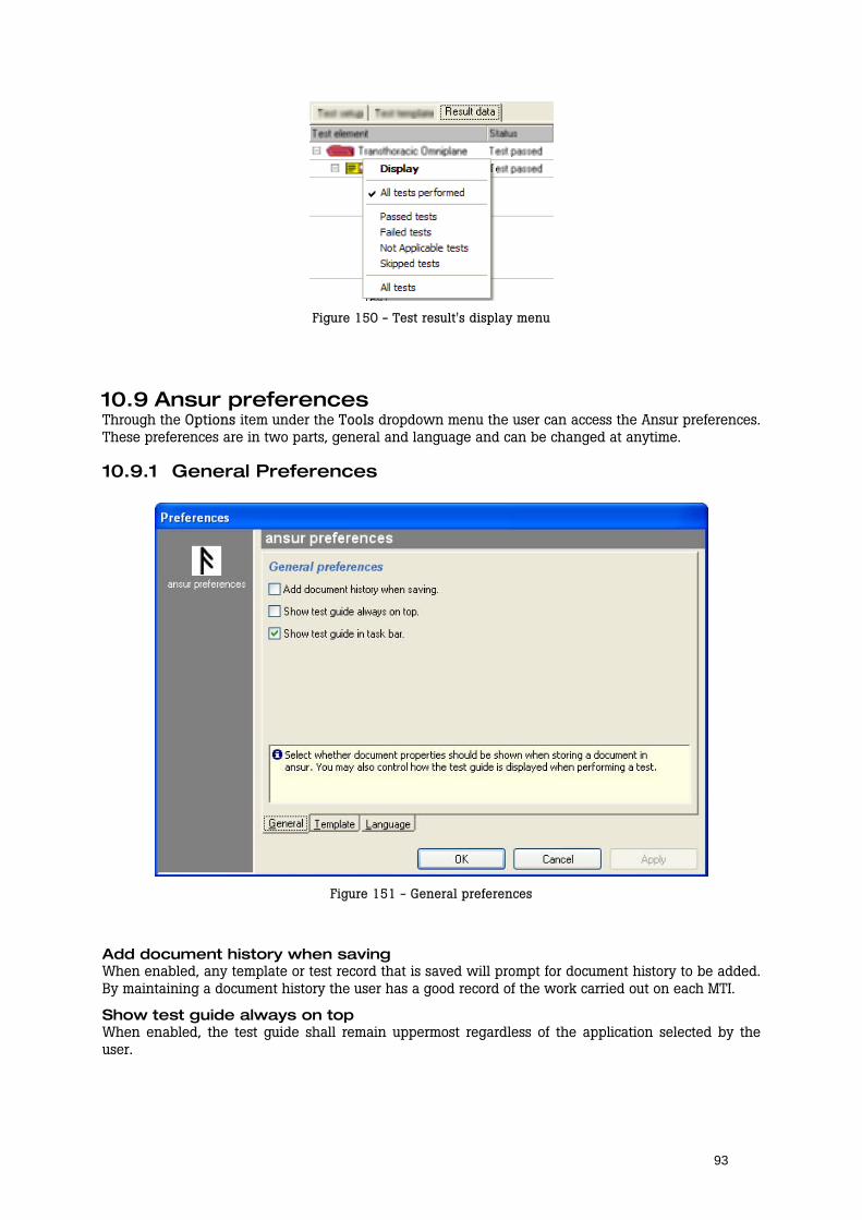
93
Figure 150 - Test result's display menu
10.9 Ansur preferences Through the Options item under the Tools dropdown menu the user can access the Ansur preferences. These preferences are in two parts, general and language and can be changed at anytime.
10.9.1 General Preferences
Figure 151 - General preferences
Add document history when saving When enabled, any template or test record that is saved will prompt for document history to be added. By maintaining a document history the user has a good record of the work carried out on each MTI.
Show test guide always on top When enabled, the test guide shall remain uppermost regardless of the application selected by the user.
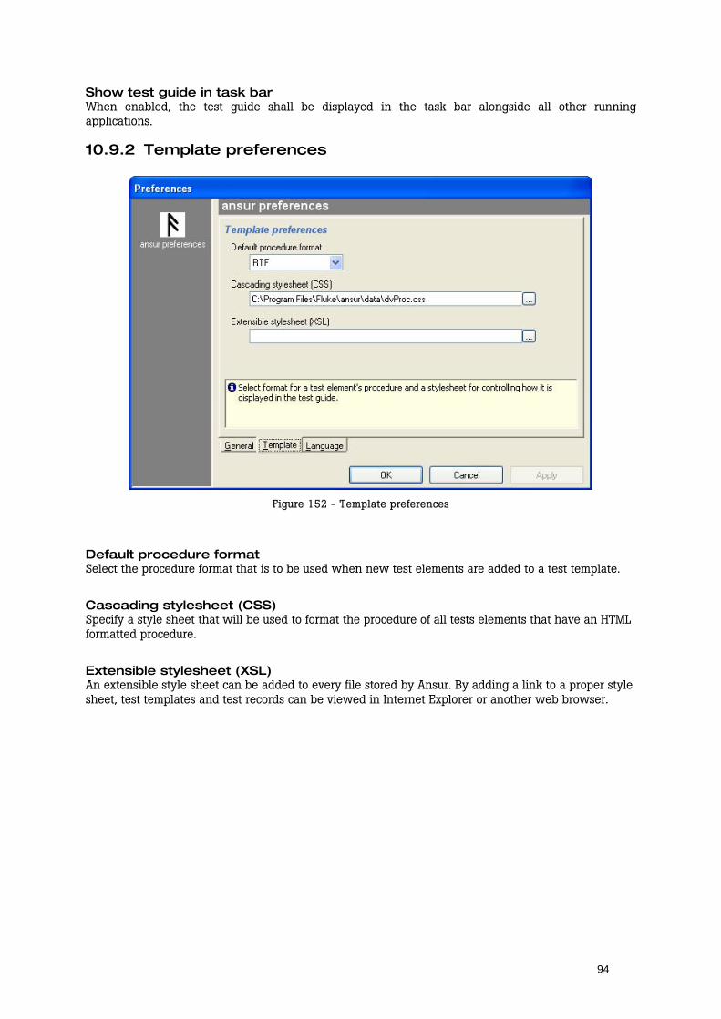
94
Show test guide in task bar When enabled, the test guide shall be displayed in the task bar alongside all other running applications.
10.9.2 Template preferences
Figure 152 - Template preferences
Default procedure format Select the procedure format that is to be used when new test elements are added to a test template.
Cascading stylesheet (CSS) Specify a style sheet that will be used to format the procedure of all tests elements that have an HTML formatted procedure.
Extensible stylesheet (XSL) An extensible style sheet can be added to every file stored by Ansur. By adding a link to a proper style sheet, test templates and test records can be viewed in Internet Explorer or another web browser.
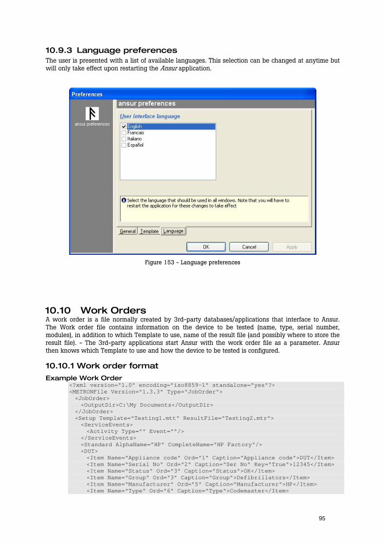
95
10.9.3 Language preferences The user is presented with a list of available languages. This selection can be changed at anytime but will only take effect upon restarting the Ansur application.
Figure 153 - Language preferences
10.10 Work Orders A work order is a file normally created by 3rd-party databases/applications that interface to Ansur. The Work order file contains information on the device to be tested (name, type, serial number, modules), in addition to which Template to use, name of the result file (and possibly where to store the result file). - The 3rd-party applications start Ansur with the work order file as a parameter. Ansur then knows which Template to use and how the device to be tested is configured.
10.10.1 Work order format
Example Work Order <?xml version="1.0" encoding="iso8859-1" standalone="yes"?> <METRONFile Version="1.3.3" Type="JobOrder"> <JobOrder> <OutputDir>C:\My Documents</OutputDir> </JobOrder> <Setup Template="Testing1.mtt" ResultFile="Testing2.mtr"> <ServiceEvents> <Activity Type="" Event=""/> </ServiceEvents> <Standard AlphaName="HP" CompleteName="HP Factory"/> <DUT> <Item Name="Appliance code" Ord="1" Caption="Appliance code">DUT</Item> <Item Name="Serial No" Ord="2" Caption="Ser No" Key="True">12345</Item> <Item Name="Status" Ord="3" Caption="Status">OK</Item> <Item Name="Group" Ord="3" Caption="Group">Defibrillators</Item> <Item Name="Manufacturer" Ord="5" Caption="Manufacturer">HP</Item> <Item Name="Type" Ord="6" Caption="Type">Codemaster</Item>
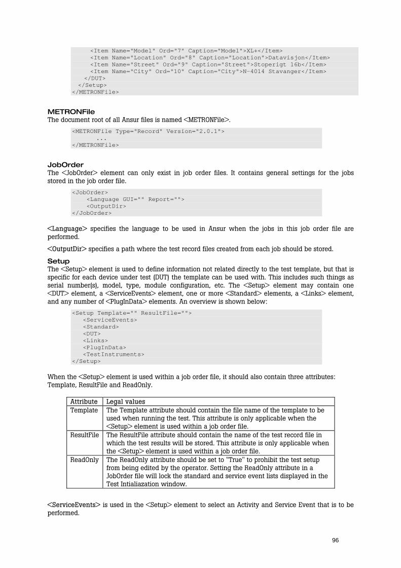
96
<Item Name="Model" Ord="7" Caption="Model">XL+</Item> <Item Name="Location" Ord="8" Caption="Location">Datavisjon</Item> <Item Name="Street" Ord="9" Caption="Street">Stoperigt 16b</Item> <Item Name="City" Ord="10" Caption="City">N-4014 Stavanger</Item> </DUT> </Setup> </METRONFile>
METRONFile The document root of all Ansur files is named <METRONFile>.
<METRONFile Type="Record" Version="2.0.1"> ... </METRONFile>
JobOrder The <JobOrder> element can only exist in job order files. It contains general settings for the jobs stored in the job order file.
<JobOrder> <Language GUI="" Report=""> <OutputDir> </JobOrder>
<Language> specifies the language to be used in Ansur when the jobs in this job order file are performed.
<OutputDir> specifies a path where the test record files created from each job should be stored.
Setup The <Setup> element is used to define information not related directly to the test template, but that is specific for each device under test (DUT) the template can be used with. This includes such things as serial number(s), model, type, module configuration, etc. The <Setup> element may contain one <DUT> element, a <ServiceEvents> element, one or more <Standard> elements, a <Links> element, and any number of <PlugInData> elements. An overview is shown below:
<Setup Template="" ResultFile=""> <ServiceEvents> <Standard> <DUT> <Links> <PlugInData> <TestInstruments> </Setup>
When the <Setup> element is used within a job order file, it should also contain three attributes: Template, ResultFile and ReadOnly.
Attribute Legal values Template The Template attribute should contain the file name of the template to be
used when running the test. This attribute is only applicable when the <Setup> element is used within a job order file.
ResultFile The ResultFile attribute should contain the name of the test record file in which the test results will be stored. This attribute is only applicable when the <Setup> element is used within a job order file.
ReadOnly The ReadOnly attribute should be set to "True" to prohibit the test setup from being edited by the operator. Setting the ReadOnly attribute in a JobOrder file will lock the standard and service event lists displayed in the Test Intialiazation window.
<ServiceEvents> is used in the <Setup> element to select an Activity and Service Event that is to be performed.
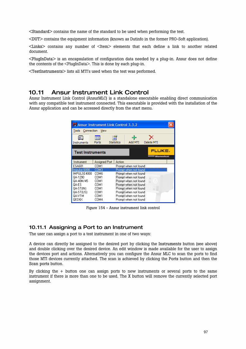
97
<Standard> contains the name of the standard to be used when performing the test.
<DUT> contains the equipment information (known as Dutinfo in the former PRO-Soft application).
<Links> contains any number of <Item> elements that each define a link to another related document.
<PlugInData> is an encapsulation of configuration data needed by a plug-in. Ansur does not define the contents of the <PlugInData>. This is done by each plug-in.
<TestInstruments> lists all MTI’s used when the test was performed.
10.11 Ansur Instrument Link Control Ansur Instrument Link Control (AnsurMLC) is a standalone executable enabling direct communication with any compatible test instrument connected. This executable is provided with the installation of the Ansur application and can be accessed directly from the start menu.
Figure 154 - Ansur instrument link control
10.11.1 Assigning a Port to an Instrument The user can assign a port to a test instrument in one of two ways: A device can directly be assigned to the desired port by clicking the Instruments button (see above) and double clicking over the desired device. An edit window is made available for the user to assign the devices port and actions. Alternatively you can configure the Ansur MLC to scan the ports to find those MTI devices currently attached. The scan is achieved by clicking the Ports button and then the Scan ports button.
By clicking the + button one can assign ports to new instruments or several ports to the same instrument if there is more than one to be used. The X button will remove the currently selected port assignment.
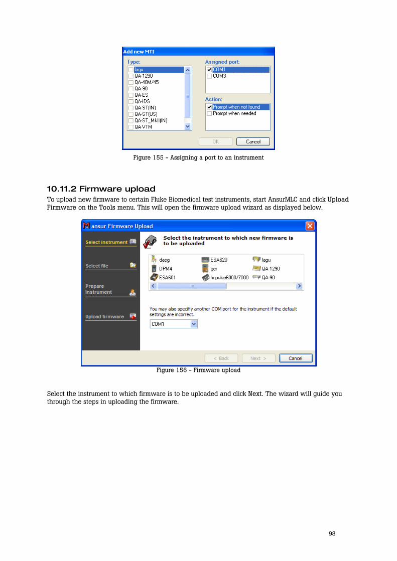
98
Figure 155 - Assigning a port to an instrument
10.11.2 Firmware upload To upload new firmware to certain Fluke Biomedical test instruments, start AnsurMLC and click Upload Firmware on the Tools menu. This will open the firmware upload wizard as displayed below.
Figure 156 - Firmware upload
Select the instrument to which firmware is to be uploaded and click Next. The wizard will guide you through the steps in uploading the firmware.
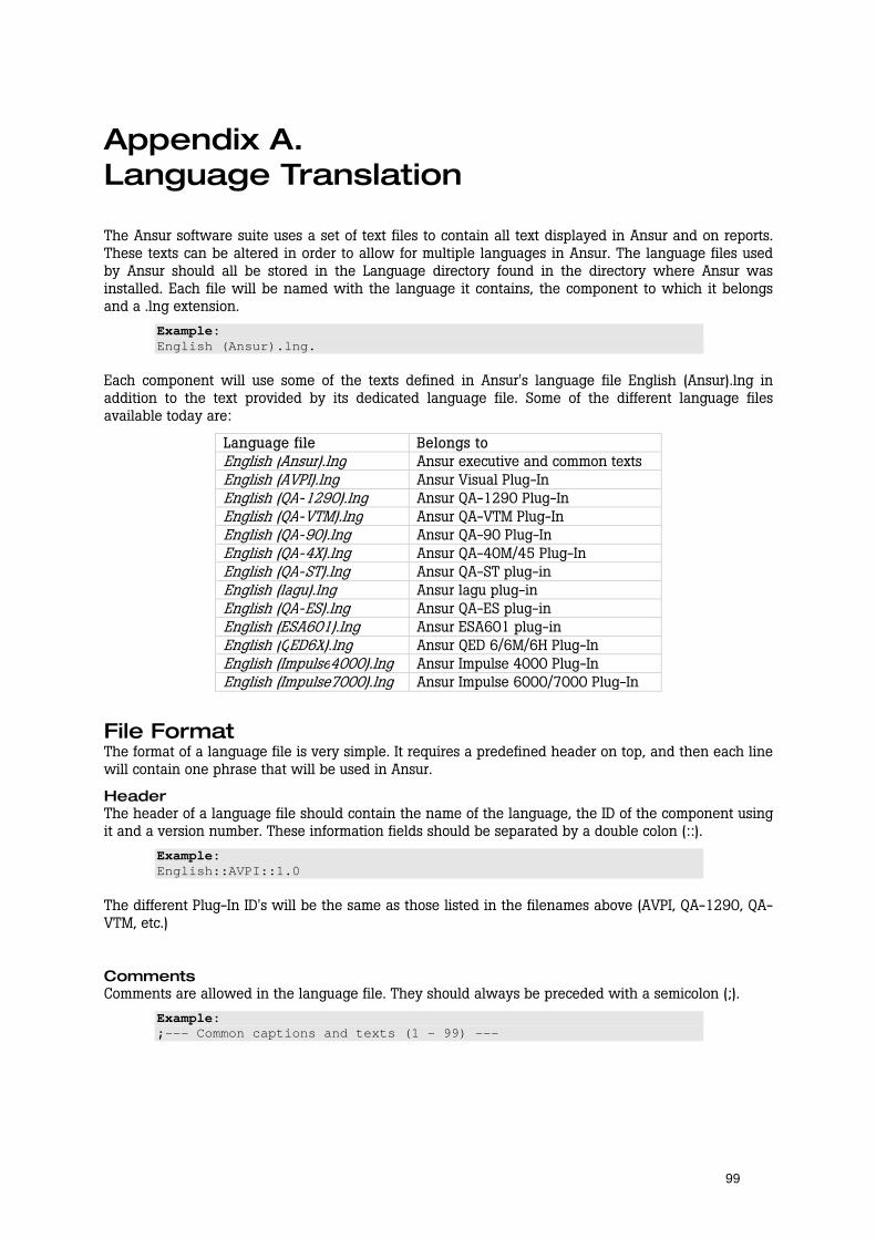
99
Appendix A. Language Translation
The Ansur software suite uses a set of text files to contain all text displayed in Ansur and on reports. These texts can be altered in order to allow for multiple languages in Ansur. The language files used by Ansur should all be stored in the Language directory found in the directory where Ansur was installed. Each file will be named with the language it contains, the component to which it belongs and a .lng extension.
Example: English (Ansur).lng.
Each component will use some of the texts defined in Ansur's language file English (Ansur).lng in addition to the text provided by its dedicated language file. Some of the different language files available today are:
Language file Belongs toEnglish (Ansur).lng Ansur executive and common texts English (AVPI).lng Ansur Visual Plug-InEnglish (QA-1290).lng Ansur QA-1290 Plug-InEnglish (QA-VTM).lng Ansur QA-VTM Plug-InEnglish (QA-90).lng Ansur QA-90 Plug-InEnglish (QA-4X).lng Ansur QA-40M/45 Plug-InEnglish (QA-ST).lng Ansur QA-ST plug-inEnglish (lagu).lng Ansur lagu plug-inEnglish (QA-ES).lng Ansur QA-ES plug-inEnglish (ESA601).lng Ansur ESA601 plug-inEnglish (QED6X).lng Ansur QED 6/6M/6H Plug-InEnglish (Impulse4000).lng Ansur Impulse 4000 Plug-InEnglish (Impulse7000).lng Ansur Impulse 6000/7000 Plug-In
File Format The format of a language file is very simple. It requires a predefined header on top, and then each line will contain one phrase that will be used in Ansur.
Header The header of a language file should contain the name of the language, the ID of the component using it and a version number. These information fields should be separated by a double colon (::).
Example: English::AVPI::1.0
The different Plug-In ID's will be the same as those listed in the filenames above (AVPI, QA-1290, QA-VTM, etc.)
Comments Comments are allowed in the language file. They should always be preceded with a semicolon (;).
Example: ;--- Common captions and texts (1 - 99) ---

100
Text entries The text entries listed in the language file consist of one numeric ID and text enclosed in apostrophes ("). The ID and the apostrophes are required and must be present in every text entry. The numeric IDs should always be in an ascending order and should never be changed.
Example: 1 "&OK"
Macros Macros can be present in the text entries. These macros are used to include variable text such as file names, error numbers and the like into the text in the text entry. The macros are designed so that different languages can place the subjects, e.g. filenames, grammatically correct. Currently the following macros are implemented:
Macro Description \n Inserts a line feed in the text. Often used in long error messages. %%X The macros named %%1 - %%5 (X being a number from 1 to 5) is used
to include variable text into the text entry. A very normal use is "Can not find the file %%1."
Example: "Page %%1 of %%2"
Creating a new language In order to create a new language a new language set should be placed in Ansur's Language directory. By following the steps below you should be able to create such a language set.
1) Create a new set of language files Create a new copy of each of the English (*).lng files currently available, and replace the language in the file name with the new language. After this you should have at least two new .lng files in the language directory plus one additional file for each installed plug-in.
2) Update the language file's header Update the header by replacing the name of the language in front of the first double colon with the name of the new language created. The ID and the version number can be left as is. This operation must be repeated for each new language file created in step (1).
3) Translate the text in the language file Replace the English text with the translated version in the new language. Note that the macros present in the text should be used also in the translated version. This operation should be repeated for each new language file created in step (1).
101
Appendix B. Configuring the report header
To change the details in the header on the print report open the header file in WordPad. The file can be located at: C:\Program Files\Fluke\Ansur\Data\arHeader.rtf.
Make the desired changes and save the file. The file can also be saved with a different file name and the path can be set in printer setup in Ansur.

102
Appendix C. Changing DUT info
DUT Info The DUT info can be changed in the registry under HKEY_LOCAL_MACHINE\SOFTWARE\Fluke\Ansur\-Executive\Test Record\DUT Info. All keys in the DUT Info key can be altered and even new keys can be added. The new settings on DUT info will apply on all new test records created and saved. Old test records will show the DUT info with the old DUT settings.
Caption The caption in the DUT info string is attached to the language file. If any changes are made to this string the language file also needs to be updated.
Key Reserved for future use
Ord The Ord key determines the order the entry will appear. The values are entered in hexadecimal.
Required Reserved for future use

103
Appendix D. Retrieving updates
Updates for Ansur are published from Fluke Biomedical’s web pages
- http://www.flukebiomedical.com/

104
Appendix E. Ansur command line interface (AAL)
Ansur implements a set of command line switches that may be used to control the behavior of the application, and send commands and data to and from Ansur. This chapter describes the commands available through the interface called Ansur Access Layer (AAL).
Run test: /r file [/h] The /r command causes Ansur to open the file specified by name and runs the test. If the /h switch is specified we will only show the windows necessary to prompt the user for information. When the test is completed, and after the user is finished viewing the test results, Ansur terminates.
Print file: /p file [/h] Prints the file given. Specifying the /h switch will cause Ansur to operate in hidden mode, and terminate when the printing is completed.
Show file: /s file The /s command starts the Ansur application, loads and displays the file specified.

105
Appendix F. Adding Standards
Standards are maintained and accessed via the registry. There are two ways to do this, firstly through a registry file and secondly by accessing the registry directly via the regedit Microsoft application.
To add standards using a registry file requires the instructions listed below.
REGEDIT4 [HKEY_LOCAL_MACHINE\Software\Fluke\Ansur\Limits] [HKEY_LOCAL_MACHINE\Software\Fluke\Ansur\Limits\<Alphaname>] "<CompleteName>"="" "#icon#"="<Icon file reference>"
The <AlphaName> is the shorthand of the <CompleteName>, the <CompleteName> being the full standard name. Any number of user-defined standards may be added into the file. Give it a filename with a “reg” extension and then double click.
Alternatively, from the start menu run the “regedit” internal Microsoft application. Search for the registry path HKEY_LOCAL_MACHINE\Software\Fluke\Ansur\Limits under which will be listed all available standards for Ansur. These standards can be edited, added or deleted at will. If deleting a standard, ensure that no existing template has used the standard as a filter.