Embed Size (px)
Citation preview
PNNL-26917
ANSI/ASHRAE/IES Standard 90.1-2016 Performance Rating Method Reference Manual
S Goel
M Rosenberg
C Eley
September 2017
PNNL-26917
ANSI/ASHRAE/IES Standard 90.1-2016 Performance Rating Method Reference Manual
S Goel
M Rosenberg
C Eley1 September 2017 Prepared for the U.S. Department of Energy under Contract DE-AC05-76RL01830 Pacific Northwest National Laboratory Richland, Washington 99352
1 Eley and Associates
iii
Acknowledgments
This document was prepared by Pacific Northwest National Laboratory (PNNL) for the U.S. Department of Energy’s (DOE’s) Building Energy Codes Program. The authors would like to thank the following organizations and individuals:
• Commercial Energy Services Network (COMNET) team for developing the framework for thisdocument through the Standard 90.1-2016 Commercial Building Energy Modeling Guidelines andProcedures.
• California Energy Commission (CEC) for providing guidance through the Nonresidential AlternativeCalculation Method (NACM) Reference Manual. The Reference Manual has been built off workoriginally done by COMNET for the Standard 90.1-2016 Commercial Building Energy ModelingGuidelines and Procedures and by CEC for the NACM Reference Manual.
• American Society of Heating, Refrigerating, and Air-Conditioning Engineers (ASHRAE) 90.1Standing Standard Project Committee (SSPC) for their insight.
• The external peer review team and advisors:
Maria Karpman, Karpman Consulting
Matt Swenka, The Weidt Group
Andrew Parker, National Renewable Energy Laboratory
Chris Balbach, Performance Systems Development
Fred Betz, Affiliated Engineers
Sagar Rao, Affiliated Engineers
Gail Hampsmire, Green Building Certification Institute
Roger Hedrick, Noresco
Michael Patterson, Trane
Fred Porter, Noresco
William Talbert, MEP Associates, LLC
• Matt Wilburn and Mark Halverson at PNNL for editorial and technical reviews.
• David Cohan, Amir Roth, Jeremiah Williams at DOE
• Bing Liu, Manager of the Building Energy Codes Program at PNNL
v
Acronyms and Abbreviations
ACH air changes per hour AFUE annual fuel utilization efficiency AHRI Air-Conditioning, Heating and Refrigeration Institute AHU air handling unit ANSI American National Standards Institute ARI Air-conditioning, Heating and Refrigeration Institute ASHRAE American Society of Heating, Refrigerating and Air-Conditioning Engineers ASTM American Society for Testing Materials BDL building design language C-factor thermal conductance CCF centum cubic feet CEC California Energy Commission CRRC Cool Roof Rating Council CFA conditioned floor area cfm cubic feet per minute CHP combined heat and power CHW chilled water COMNET Commercial Energy Services Network COP coefficient of performance DCV demand controlled ventilation DDC dynamic demand control DOAS dedicated outdoor air system DV displacement ventilation DOE U.S. Department of Energy DX direct expansion EA effective aperture Ec combustion efficiency EF energy factor EER energy efficiency ratio EFLH equivalent full load hours EIA Energy Information Administration EILP exterior installed lighting power EIR energy input ratio ELAP exterior lighting power allowance ERV energy recovery ventilator Et thermal efficiency
vi
F-factor heat transfer coefficient of a slab edge unit of perimeter length FPLR function of part load ratio FT function of temperature HSPF heating seasonal performance factor HVAC heating, ventilation, and air conditioning HW hot water IES Illuminating Engineering Society ILPA interior lighting power allowance kBtu/hr thousand British thermal units per hour LPD lighting power density MBH thousand British thermal units per hour MCF thousand cubic feet MBtu thousand British thermal units MJ megajoule MMBtu million British thermal units NACM Non-residential Alternate Calculation Method NAECA National Appliance Energy Conservation Act NFRC National Fenestration Rating Council OA outdoor air OAT outdoor air temperature PAF power adjustment factor PFP parallel fan powered PIU powered induction unit PLF part-load fraction PNNL Pacific Northwest National Laboratory PSZ-AC packaged single zone air conditioner PTAC packaged terminal air conditioner PTHP packaged terminal heat pump PRM Performance Rating Method PVAV packaged variable air volume RCR room cavity ratio RDP relative daylight potential SAT supply air temperature SEER seasonal energy efficiency ratio SHGC solar heat gain coefficient SO source orientation SRR skylight roof ratio SSPC Standing Standard Project Committee
vii
TOU time of use U-factor thermal transmittance UFAD underfloor air distribution system UMLH unmet load hours VAV variable air volume VRP ventilation rate procedure VT visible light transmittance W watt w.c. water column WSHP water source heat pump WWR window-to-wall ratio
ix
Contents
Acknowledgments ........................................................................................................................................ iii Acronyms and Abbreviations ....................................................................................................................... v 1.0 Overview ........................................................................................................................................... 1.1
1.1 Purpose ...................................................................................................................................... 1.1 1.2 Applications of the PRM-RM ................................................................................................... 1.1 1.3 Standard 90.1-2016 Performance Rating Method Compliance Calculations ............................ 1.2 1.4 Organization .............................................................................................................................. 1.4 1.5 Type of Project Submittal ......................................................................................................... 1.4
2.0 General Modeling Procedures ........................................................................................................... 2.5 2.1 General Requirements for Data from the User .......................................................................... 2.5
2.1.1 General ........................................................................................................................... 2.5 2.1.2 Definition of Building Descriptors ................................................................................. 2.5 2.1.3 Treatment of Descriptors Not Fully Addressed by this Document ................................ 2.6 2.1.4 Regulated and Unregulated Energy Use ........................................................................ 2.6
2.2 Thermal Blocks, HVAC Zones, and Space Functions .............................................................. 2.7 2.2.1 Definitions ...................................................................................................................... 2.7
2.3 Modeling Requirements for Zones ............................................................................................ 2.9 2.3.1 Required Zone Modeling Capabilities ........................................................................... 2.9 2.3.2 Modeling Requirements for Unconditioned Spaces ....................................................... 2.9 2.3.3 Modeling Requirements for Parking Garages, Attics, and Crawlspaces ...................... 2.10 2.3.4 Modeling Requirements for Semi-Heated Spaces ........................................................ 2.11 2.3.5 Space Use Classification .............................................................................................. 2.11
2.4 Unmet Load Hours .................................................................................................................. 2.12 2.5 Calculation Procedures ............................................................................................................ 2.13 2.6 HVAC Capacity Requirements and Sizing ............................................................................. 2.15
2.6.1 Specifying HVAC Capacities for the Proposed Design ............................................... 2.15 2.6.2 Sizing Equipment in the Baseline Building ................................................................. 2.16 2.6.3 Proposed Design with No HVAC Equipment .............................................................. 2.17
3.0 Building Descriptors Reference ......................................................................................................... 3.1 3.1 Overview ................................................................................................................................... 3.1
3.1.1 HVAC System Map ....................................................................................................... 3.1 3.1.2 Organization of Information ......................................................................................... 3.10 3.1.3 General Information ..................................................................................................... 3.10 3.1.4 Building Model Classification ..................................................................................... 3.12 3.1.5 Geographic and Climate Data ...................................................................................... 3.14 3.1.6 Site Characteristics ....................................................................................................... 3.19
x
3.1.7 Calendar ....................................................................................................................... 3.19 3.1.8 Simulation Control ....................................................................................................... 3.20
3.2 HVAC Zones ........................................................................................................................... 3.21 3.2.1 General Information ..................................................................................................... 3.21 3.2.2 Interior Lighting ........................................................................................................... 3.26 3.2.3 Receptacle and Process Loads ...................................................................................... 3.26 3.2.4 Occupants ..................................................................................................................... 3.27 3.2.5 Infiltration..................................................................................................................... 3.28 3.2.6 Natural Ventilation ....................................................................................................... 3.31 3.2.7 Thermal Mass ............................................................................................................... 3.35
3.3 Space Uses .............................................................................................................................. 3.36 3.3.1 General Information ..................................................................................................... 3.36 3.3.2 Occupants ..................................................................................................................... 3.37 3.3.3 Interior Lighting ........................................................................................................... 3.38 3.3.4 Daylighting Control ...................................................................................................... 3.46 3.3.5 Receptacle and Process Loads ...................................................................................... 3.56 3.3.6 Commercial Refrigeration Equipment ......................................................................... 3.61 3.3.7 Elevators, Escalators, and Moving Walkways ............................................................. 3.68 3.3.8 Gas Process Equipment ................................................................................................ 3.72
3.4 Building Envelope Data .......................................................................................................... 3.75 3.4.1 Building Orientation ..................................................................................................... 3.75 3.4.2 Materials ....................................................................................................................... 3.76 3.4.3 Construction Assemblies .............................................................................................. 3.77 3.4.4 Roofs ............................................................................................................................ 3.79 3.4.5 Exterior Wall ................................................................................................................ 3.82 3.4.6 Exterior Floors.............................................................................................................. 3.86 3.4.7 Doors ............................................................................................................................ 3.89 3.4.8 Fenestration .................................................................................................................. 3.90 3.4.9 Below-Grade Walls ...................................................................................................... 3.97 3.4.10 Slab Floors in Contact with Ground ............................................................................. 3.99 3.4.11 Heat Transfer between Thermal Zones ...................................................................... 3.101
3.5 HVAC Zone Level Systems .................................................................................................. 3.102 3.5.1 Zone Temperature Control ......................................................................................... 3.102 3.5.2 Terminal Device Data ................................................................................................ 3.103 3.5.3 Terminal Heating ........................................................................................................ 3.104 3.5.4 Baseboard Heat .......................................................................................................... 3.106 3.5.5 Zone Level Airflow .................................................................................................... 3.106
3.6 HVAC Secondary Systems ................................................................................................... 3.124 3.6.1 Basic System Information .......................................................................................... 3.132
xi
3.6.2 System Controls ......................................................................................................... 3.135 3.6.3 Fan Systems................................................................................................................ 3.143 3.6.4 Outdoor Air Controls and Economizers ..................................................................... 3.162 3.6.5 Cooling Systems ......................................................................................................... 3.167 3.6.6 Heating Systems ......................................................................................................... 3.191 3.6.7 Humidity Controls and Devices ................................................................................. 3.206
3.7 HVAC Primary Systems ....................................................................................................... 3.212 3.7.1 Boilers ........................................................................................................................ 3.212 3.7.2 Chillers ....................................................................................................................... 3.220 3.7.3 Cooling Towers .......................................................................................................... 3.231 3.7.4 Fluid Economizers ...................................................................................................... 3.240 3.7.5 Pumps ......................................................................................................................... 3.243 3.7.6 Thermal Storage ......................................................................................................... 3.254 3.7.7 Heat Recovery Equipment.......................................................................................... 3.257 3.7.8 Plant Management ...................................................................................................... 3.260
3.8 Miscellaneous Energy Uses .................................................................................................. 3.261 3.8.1 Water Heating ............................................................................................................ 3.261 3.8.2 Swimming Pools ........................................................................................................ 3.275 3.8.3 Transformers .............................................................................................................. 3.278 3.8.4 Exterior Lighting ........................................................................................................ 3.278 3.8.5 Other Electricity Use .................................................................................................. 3.285 3.8.6 Other Gas Use ............................................................................................................ 3.286
3.9 On-Site Power Generation .................................................................................................... 3.286 3.9.1 Photovoltaic Systems ................................................................................................. 3.287 3.9.2 Wind Systems ............................................................................................................. 3.293
3.10 Common Data Structures ...................................................................................................... 3.294 3.10.1 Schedule ..................................................................................................................... 3.294 3.10.2 Holidays ..................................................................................................................... 3.295 3.10.3 Surface Geometry ....................................................................................................... 3.295 3.10.4 Opening Geometry ..................................................................................................... 3.295 3.10.5 Opening Shade ........................................................................................................... 3.295 3.10.6 Construction Assembly .............................................................................................. 3.296 3.10.7 Fenestration Construction .......................................................................................... 3.296 3.10.8 Material ...................................................................................................................... 3.296 3.10.9 Slab Construction ....................................................................................................... 3.296 3.10.10 Exterior Surface Properties ..................................................................................... 3.296 3.10.11 Occupant Heat Rate ................................................................................................ 3.296 3.10.12 Furniture and Contents ............................................................................................ 3.296 3.10.13 Reference Position in a Space ................................................................................. 3.297
xii
3.10.14 Two Dimensional Curve ......................................................................................... 3.297 3.10.15 Three Dimensional Curve ....................................................................................... 3.297 3.10.16 Temperature Reset Schedule ................................................................................... 3.297
4.0 Energy Price Data .............................................................................................................................. 4.1 4.1 State Average Energy Costs ...................................................................................................... 4.1 4.2 Custom Energy Costs ................................................................................................................ 4.2
4.2.1 Utility Costs: Tariffs ....................................................................................................... 4.2 4.2.2 Utility Costs: Charges .................................................................................................... 4.6 4.2.3 Utility Costs: Ratchets .................................................................................................. 4.11
5.0 Reporting ........................................................................................................................................... 5.1 5.1 Content ...................................................................................................................................... 5.1
5.1.1 Building Summary ......................................................................................................... 5.2 5.1.2 Performance Outputs ...................................................................................................... 5.2 5.1.3 Model Input Documentation .......................................................................................... 5.7 5.1.4 Representations ............................................................................................................ 5.21 5.1.5 Supporting Documentation .......................................................................................... 5.22
5.2 Format of Report ..................................................................................................................... 5.22 6.0 References ......................................................................................................................................... 6.1
xiii
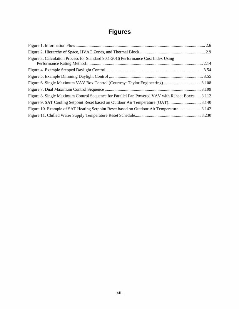
Figures
Figure 1. Information Flow ........................................................................................................................ 2.6 Figure 2. Hierarchy of Space, HVAC Zones, and Thermal Block............................................................. 2.9 Figure 3. Calculation Process for Standard 90.1-2016 Performance Cost Index Using
Performance Rating Method ............................................................................................................ 2.14 Figure 4. Example Stepped Daylight Control .......................................................................................... 3.54 Figure 5. Example Dimming Daylight Control ....................................................................................... 3.55 Figure 6. Single Maximum VAV Box Control (Courtesy: Taylor Engineering) ................................... 3.108 Figure 7. Dual Maximum Control Sequence ......................................................................................... 3.109 Figure 8. Single Maximum Control Sequence for Parallel Fan Powered VAV with Reheat Boxes ..... 3.112 Figure 9. SAT Cooling Setpoint Reset based on Outdoor Air Temperature (OAT) .............................. 3.140 Figure 10. Example of SAT Heating Setpoint Reset based on Outdoor Air Temperature. ................... 3.142 Figure 11. Chilled Water Supply Temperature Reset Schedule............................................................. 3.230
xiv
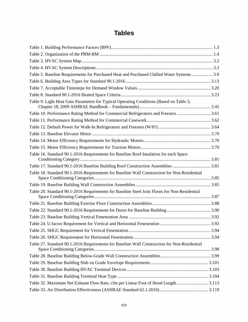
Tables
Table 1. Building Performance Factors (BPF) ........................................................................................... 1.3 Table 2. Organization of the PRM-RM ..................................................................................................... 1.4 Table 3. HVAC System Map ..................................................................................................................... 3.2 Table 4. HVAC System Descriptions ........................................................................................................ 3.3 Table 5. Baseline Requirements for Purchased Heat and Purchased Chilled Water Systems ................... 3.9 Table 6. Building Area Types for Standard 90.1-2016 ............................................................................ 3.13 Table 7. Acceptable Timesteps for Demand Window Values ................................................................. 3.20 Table 8. Standard 90.1-2016 Heated Space Criteria ................................................................................ 3.23 Table 9. Light Heat Gain Parameters for Typical Operating Conditions (Based on Table 3,
Chapter 18, 2009 ASHRAE Handbook – Fundamentals)................................................................ 3.45 Table 10. Performance Rating Method for Commercial Refrigerators and Freezers .............................. 3.61 Table 11. Performance Rating Method for Commercial Casework ......................................................... 3.62 Table 12. Default Power for Walk-In Refrigerators and Freezers (W/ft²) ............................................... 3.64 Table 13. Baseline Elevator Motor .......................................................................................................... 3.70 Table 14. Motor Efficiency Requirements for Hydraulic Motors ............................................................ 3.70 Table 15. Motor Efficiency Requirements for Traction Motors .............................................................. 3.70 Table 16. Standard 90.1-2016 Requirements for Baseline Roof Insulation for each Space
Conditioning Category ..................................................................................................................... 3.81 Table 17. Standard 90.1-2016 Baseline Building Roof Construction Assemblies .................................. 3.81 Table 18. Standard 90.1-2016 Requirements for Baseline Wall Construction for Non-Residential
Space Conditioning Categories ........................................................................................................ 3.85 Table 19. Baseline Building Wall Construction Assemblies ................................................................... 3.85 Table 20. Standard 90.1-2016 Requirements for Baseline Steel Joist Floors for Non-Residential
Space Conditioning Categories ........................................................................................................ 3.87 Table 21. Baseline Building Exterior Floor Construction Assemblies .................................................... 3.88 Table 22. Standard 90.1-2016 Requirements for Doors for Baseline Building ....................................... 3.90 Table 23. Baseline Building Vertical Fenestration Area ......................................................................... 3.92 Table 24. U-factor Requirement for Vertical and Horizontal Fenestration ............................................. 3.93 Table 25. SHGC Requirement for Vertical Fenestration ......................................................................... 3.94 Table 26. SHGC Requirement for Horizontal Fenestration ..................................................................... 3.94 Table 27. Standard 90.1-2016 Requirements for Baseline Wall Construction for Non-Residential
Space Conditioning Categories ........................................................................................................ 3.98 Table 28. Baseline Building Below-Grade Wall Construction Assemblies............................................. 3.99 Table 29. Baseline Building Slab on Grade Envelope Requirements .................................................... 3.101 Table 30. Baseline Building HVAC Terminal Devices ......................................................................... 3.103 Table 31. Baseline Building Terminal Heat Type ................................................................................. 3.104 Table 32. Maximum Net Exhaust Flow Rate, cfm per Linear Foot of Hood Length ............................ 3.113 Table 33. Air Distribution Effectiveness (ASHRAE Standard 62.1-2010) ........................................... 3.119
xv
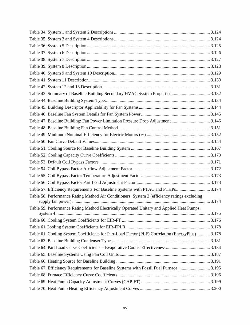
Table 34. System 1 and System 2 Descriptions ..................................................................................... 3.124 Table 35. System 3 and System 4 Descriptions ..................................................................................... 3.124 Table 36. System 5 Description ............................................................................................................. 3.125 Table 37. System 6 Description ............................................................................................................. 3.126 Table 38. System 7 Description ............................................................................................................. 3.127 Table 39. System 8 Description ............................................................................................................. 3.128 Table 40. System 9 and System 10 Description ..................................................................................... 3.129 Table 41. System 11 Description ........................................................................................................... 3.130 Table 42. System 12 and 13 Description ............................................................................................... 3.131 Table 43. Summary of Baseline Building Secondary HVAC System Properties .................................. 3.132 Table 44. Baseline Building System Type ............................................................................................. 3.134 Table 45. Building Descriptor Applicability for Fan Systems ............................................................... 3.144 Table 46. Baseline Fan System Details for Fan System Power ............................................................. 3.145 Table 47. Baseline Building: Fan Power Limitation Pressure Drop Adjustment .................................. 3.146 Table 48. Baseline Building Fan Control Method ................................................................................. 3.151 Table 49. Minimum Nominal Efficiency for Electric Motors (%) ........................................................ 3.152 Table 50. Fan Curve Default Values ...................................................................................................... 3.154 Table 51. Cooling Source for Baseline Building System ...................................................................... 3.167 Table 52. Cooling Capacity Curve Coefficients .................................................................................... 3.170 Table 53. Default Coil Bypass Factors .................................................................................................. 3.171 Table 54. Coil Bypass Factor Airflow Adjustment Factor .................................................................... 3.172 Table 55. Coil Bypass Factor Temperature Adjustment Factor ............................................................. 3.173 Table 56. Coil Bypass Factor Part Load Adjustment Factor ................................................................. 3.173 Table 57. Efficiency Requirements For Baseline Systems with PTAC and PTHPs .............................. 3.174 Table 58. Performance Rating Method Air Conditioners: System 3 (efficiency ratings excluding
supply fan power) .......................................................................................................................... 3.174 Table 59. Performance Rating Method Electrically Operated Unitary and Applied Heat Pumps:
System 4 ......................................................................................................................................... 3.175 Table 60. Cooling System Coefficients for EIR-FT .............................................................................. 3.176 Table 61.Cooling System Coefficients for EIR-FPLR .......................................................................... 3.178 Table 61. Cooling System Coefficients for Part-Load Factor (PLF) Correlation (EnergyPlus) ............ 3.178 Table 63. Baseline Building Condenser Type ....................................................................................... 3.181 Table 64. Part Load Curve Coefficients – Evaporative Cooler Effectiveness ....................................... 3.184 Table 65. Baseline Systems Using Fan Coil Units ................................................................................ 3.187 Table 66. Heating Source for Baseline Building ................................................................................... 3.191 Table 67. Efficiency Requirements for Baseline Systems with Fossil Fuel Furnace ............................ 3.195 Table 68. Furnace Efficiency Curve Coefficients .................................................................................. 3.196 Table 69. Heat Pump Capacity Adjustment Curves (CAP-FT) ............................................................. 3.199 Table 70. Heat Pump Heating Efficiency Adjustment Curves .............................................................. 3.200
xvi
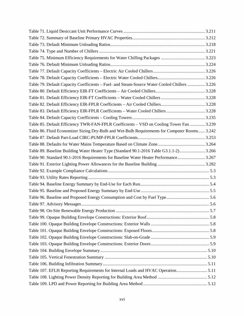
Table 71. Liquid Desiccant Unit Performance Curves .......................................................................... 3.211 Table 72. Summary of Baseline Primary HVAC Properties .................................................................. 3.212 Table 73. Default Minimum Unloading Ratios...................................................................................... 3.218 Table 74. Type and Number of Chillers ................................................................................................ 3.221 Table 75. Minimum Efficiency Requirements for Water Chilling Packages ........................................ 3.223 Table 76. Default Minimum Unloading Ratios...................................................................................... 3.224 Table 77. Default Capacity Coefficients – Electric Air Cooled Chillers ............................................... 3.226 Table 78. Default Capacity Coefficients – Electric Water Cooled Chillers ........................................... 3.226 Table 79. Default Capacity Coefficients – Fuel- and Steam-Source Water Cooled Chillers ................ 3.226 Table 80. Default Efficiency EIR-FT Coefficients – Air Cooled Chillers ............................................. 3.228 Table 81. Default Efficiency EIR-FT Coefficients – Water Cooled Chillers ........................................ 3.228 Table 82. Default Efficiency EIR-FPLR Coefficients – Air Cooled Chillers ........................................ 3.228 Table 83. Default Efficiency EIR-FPLR Coefficients – Water Cooled Chillers ................................... 3.228 Table 84. Default Capacity Coefficients – Cooling Towers .................................................................. 3.235 Table 85. Default Efficiency TWR-FAN-FPLR Coefficients – VSD on Cooling Tower Fan .............. 3.239 Table 86. Fluid Economizer Sizing Dry-Bulb and Wet-Bulb Requirements for Computer Rooms ...... 3.242 Table 87. Default Part-Load CIRC-PUMP-FPLR Coefficients ............................................................. 3.253 Table 88. Defaults for Water Mains Temperature Based on Climate Zone ........................................... 3.264 Table 89. Baseline Building Water Heater Type (Standard 90.1-2016 Table G3.1.1-2) ....................... 3.266 Table 90. Standard 90.1-2016 Requirements for Baseline Water Heater Performance ......................... 3.267 Table 91. Exterior Lighting Power Allowances for the Baseline Building ........................................... 3.282 Table 92. Example Compliance Calculations ............................................................................................ 5.3 Table 93. Utility Rates Reporting .............................................................................................................. 5.3 Table 94. Baseline Energy Summary by End-Use for Each Run............................................................... 5.4 Table 95. Baseline and Proposed Energy Summary by End-Use .............................................................. 5.5 Table 96. Baseline and Proposed Energy Consumption and Cost by Fuel Type ....................................... 5.6 Table 97. Advisory Messages .................................................................................................................... 5.6 Table 98. On-Site Renewable Energy Production ..................................................................................... 5.7 Table 99. Opaque Building Envelope Constructions: Exterior Roof ......................................................... 5.8 Table 100. Opaque Building Envelope Constructions: Exterior Walls ..................................................... 5.8 Table 101. Opaque Building Envelope Constructions: Exposed Floors .................................................... 5.8 Table 102. Opaque Building Envelope Constructions: Slab-on-Grade ..................................................... 5.9 Table 103. Opaque Building Envelope Constructions: Exterior Doors ..................................................... 5.9 Table 104. Building Envelope Summary ................................................................................................. 5.10 Table 105. Vertical Fenestration Summary ............................................................................................. 5.10 Table 106. Building Infiltration Summary ............................................................................................... 5.11 Table 107. EFLH Reporting Requirements for Internal Loads and HVAC Operation ............................ 5.11 Table 108. Lighting Power Density Reporting for Building Area Method ............................................. 5.12 Table 109. LPD and Power Reporting for Building Area Method .......................................................... 5.12
xvii
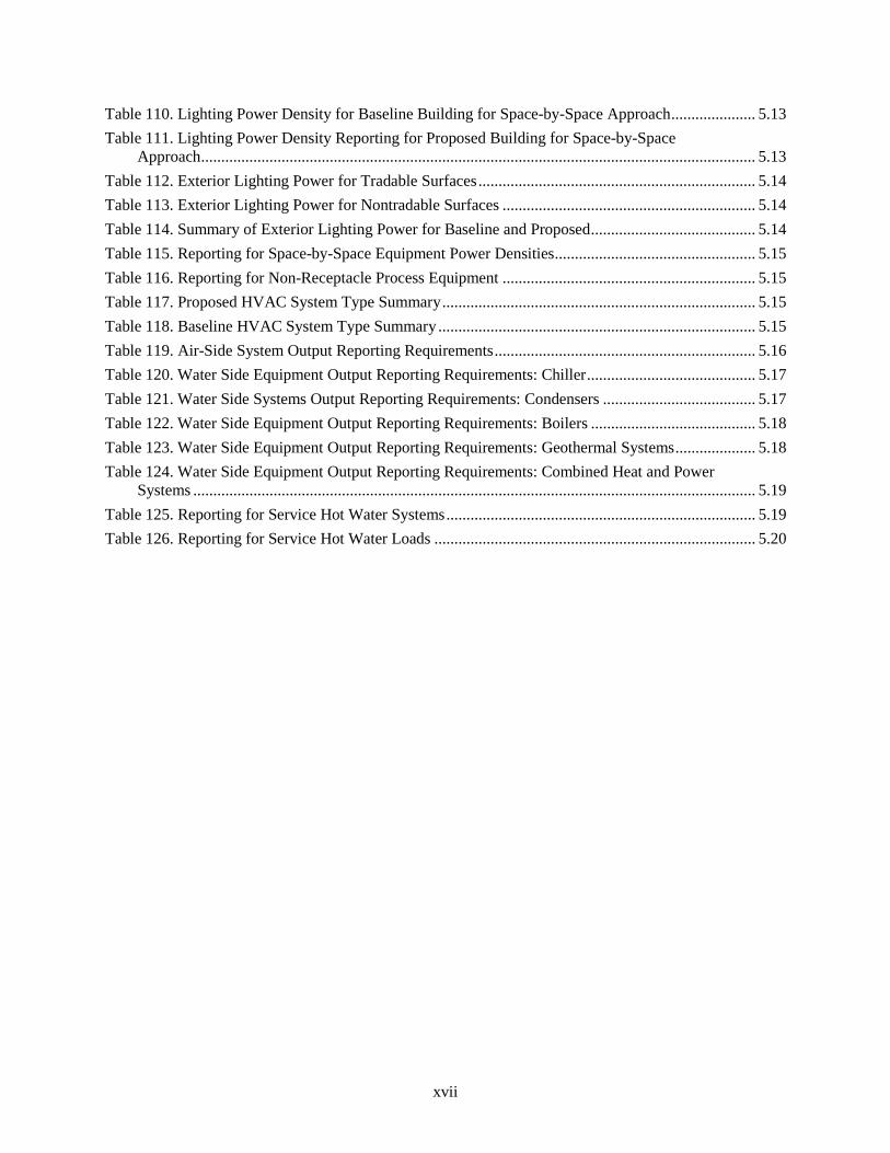
Table 110. Lighting Power Density for Baseline Building for Space-by-Space Approach ..................... 5.13 Table 111. Lighting Power Density Reporting for Proposed Building for Space-by-Space
Approach .......................................................................................................................................... 5.13 Table 112. Exterior Lighting Power for Tradable Surfaces ..................................................................... 5.14 Table 113. Exterior Lighting Power for Nontradable Surfaces ............................................................... 5.14 Table 114. Summary of Exterior Lighting Power for Baseline and Proposed ......................................... 5.14 Table 115. Reporting for Space-by-Space Equipment Power Densities .................................................. 5.15 Table 116. Reporting for Non-Receptacle Process Equipment ............................................................... 5.15 Table 117. Proposed HVAC System Type Summary .............................................................................. 5.15 Table 118. Baseline HVAC System Type Summary ............................................................................... 5.15 Table 119. Air-Side System Output Reporting Requirements ................................................................. 5.16 Table 120. Water Side Equipment Output Reporting Requirements: Chiller .......................................... 5.17 Table 121. Water Side Systems Output Reporting Requirements: Condensers ...................................... 5.17 Table 122. Water Side Equipment Output Reporting Requirements: Boilers ......................................... 5.18 Table 123. Water Side Equipment Output Reporting Requirements: Geothermal Systems .................... 5.18 Table 124. Water Side Equipment Output Reporting Requirements: Combined Heat and Power
Systems ............................................................................................................................................ 5.19 Table 125. Reporting for Service Hot Water Systems ............................................................................. 5.19 Table 126. Reporting for Service Hot Water Loads ................................................................................ 5.20
1.1
1.0 Overview
1.1 Purpose
This document is intended to be a reference manual for the Appendix G Performance Rating Method (PRM) of ANSI/ASHRAE/IES Standard 90.1-2016 (Standard 90.1-2016). The PRM can be used to demonstrate compliance with the standard and to rate the energy efficiency of commercial and high-rise residential buildings with designs that exceed the requirements of Standard 90.1. Use of the PRM for demonstrating compliance with Standard 90.1 is a new feature of the 2016 edition. The procedures and processes described in the PRM reference manual (PRM-RM) are designed to provide consistency and accuracy by filling in gaps and providing additional details needed by users of the PRM. Note that this document has been created independently from ASHRAE and Standing Standard Project Committee (SSPC) 90.1 and is neither sanctioned nor approved by either of those entities.
Interpretations to Standard 90.1-2016 Code requirements can be found out here1. Users can also request official interpretations to code requirements out here2. In cases where the official interpretation conflicts with interpretations provided by the PRM-RM, the official interpretations should be used.
1.2 Applications of the PRM-RM
Users of this manual include energy modelers, software developers, and program administrators.
• Energy Modelers. When available, modelers can use software that automatically generates the baseline building, and refer to PRM-RM for rules on generating the model of the proposed design. Else, energy modeler can also manually apply the PRM-RM modeling rules and procedures to create the baseline buildings.
• Software Developers. Software developers can use the PRM-RM modeling guidelines to customize their software to automatically create the baseline building model and assure that schedules and other modeling assumptions are neutral. The PRM-RM also defines contents for a standard output reports that address the reporting requirements as defined for the PRM as well as United States Green Building Council’s (USGBC) Leadership in Energy and Environmental Design ( LEED) certification.
• Program Administrators. Program administrators, code officials and rating authorities that administer incentive programs that are based on the PRM of Standard 90.1-2016. Program administrators can use this document to better understand the building modeling requirements.
1 https://www.ashrae.org/standards-research--technology/standards-interpretations/interpretations-for-standard-90-1-2016 2 https://www.ashrae.org/standards-research--technology/standards-forms--procedures/how-to-request-an-interpretation
1.2
1.3 Standard 90.1-2016 Performance Rating Method Compliance Calculations
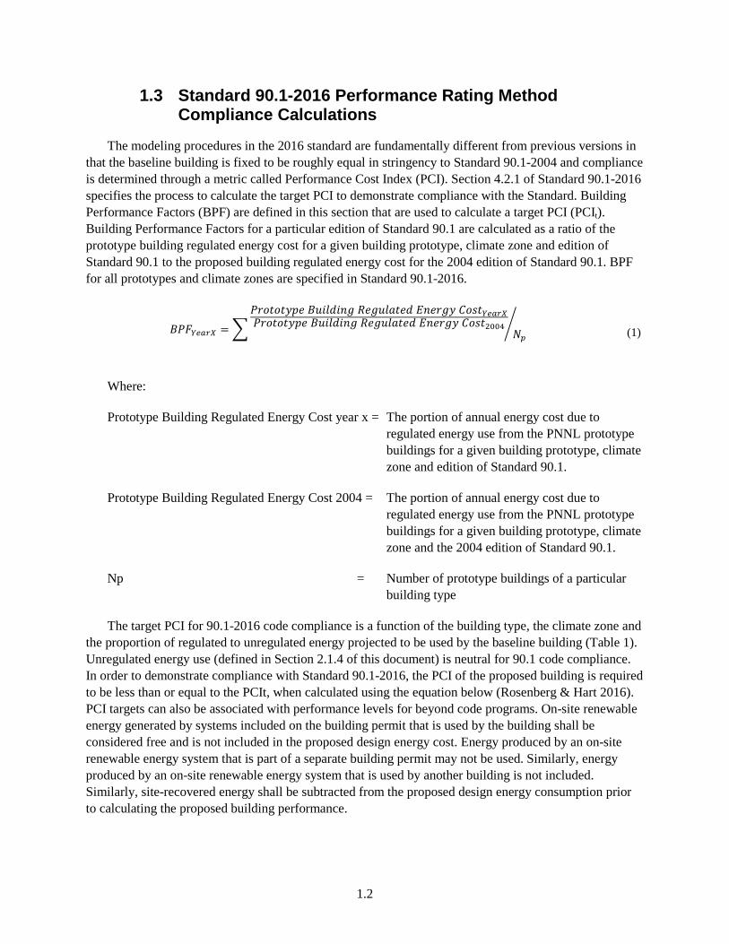
The modeling procedures in the 2016 standard are fundamentally different from previous versions in that the baseline building is fixed to be roughly equal in stringency to Standard 90.1-2004 and compliance is determined through a metric called Performance Cost Index (PCI). Section 4.2.1 of Standard 90.1-2016 specifies the process to calculate the target PCI to demonstrate compliance with the Standard. Building Performance Factors (BPF) are defined in this section that are used to calculate a target PCI (PCIt). Building Performance Factors for a particular edition of Standard 90.1 are calculated as a ratio of the prototype building regulated energy cost for a given building prototype, climate zone and edition of Standard 90.1 to the proposed building regulated energy cost for the 2004 edition of Standard 90.1. BPF for all prototypes and climate zones are specified in Standard 90.1-2016.
𝐵𝐵𝐵𝐵𝐵𝐵𝑌𝑌𝑌𝑌𝑌𝑌𝑌𝑌𝑌𝑌 = �𝐵𝐵𝑃𝑃𝑃𝑃𝑃𝑃𝑃𝑃𝑃𝑃𝑃𝑃𝑃𝑃𝑃𝑃 𝐵𝐵𝐵𝐵𝐵𝐵𝐵𝐵𝐵𝐵𝐵𝐵𝐵𝐵𝐵𝐵 𝑅𝑅𝑃𝑃𝐵𝐵𝐵𝐵𝐵𝐵𝑅𝑅𝑃𝑃𝑃𝑃𝐵𝐵 𝐸𝐸𝐵𝐵𝑃𝑃𝑃𝑃𝐵𝐵𝑃𝑃 𝐶𝐶𝑃𝑃𝐶𝐶𝑃𝑃𝑌𝑌𝑌𝑌𝑌𝑌𝑌𝑌𝑌𝑌𝐵𝐵𝑃𝑃𝑃𝑃𝑃𝑃𝑃𝑃𝑃𝑃𝑃𝑃𝑃𝑃𝑃𝑃 𝐵𝐵𝐵𝐵𝐵𝐵𝐵𝐵𝐵𝐵𝐵𝐵𝐵𝐵𝐵𝐵 𝑅𝑅𝑃𝑃𝐵𝐵𝐵𝐵𝐵𝐵𝑅𝑅𝑃𝑃𝑃𝑃𝐵𝐵 𝐸𝐸𝐵𝐵𝑃𝑃𝑃𝑃𝐵𝐵𝑃𝑃 𝐶𝐶𝑃𝑃𝐶𝐶𝑃𝑃2004
𝑁𝑁𝑝𝑝� (1)
Where:
Prototype Building Regulated Energy Cost year x = The portion of annual energy cost due to regulated energy use from the PNNL prototype buildings for a given building prototype, climate zone and edition of Standard 90.1.
Prototype Building Regulated Energy Cost 2004 = The portion of annual energy cost due to regulated energy use from the PNNL prototype buildings for a given building prototype, climate zone and the 2004 edition of Standard 90.1.
Np = Number of prototype buildings of a particular building type
The target PCI for 90.1-2016 code compliance is a function of the building type, the climate zone and the proportion of regulated to unregulated energy projected to be used by the baseline building (Table 1). Unregulated energy use (defined in Section 2.1.4 of this document) is neutral for 90.1 code compliance. In order to demonstrate compliance with Standard 90.1-2016, the PCI of the proposed building is required to be less than or equal to the PCIt, when calculated using the equation below (Rosenberg & Hart 2016). PCI targets can also be associated with performance levels for beyond code programs. On-site renewable energy generated by systems included on the building permit that is used by the building shall be considered free and is not included in the proposed design energy cost. Energy produced by an on-site renewable energy system that is part of a separate building permit may not be used. Similarly, energy produced by an on-site renewable energy system that is used by another building is not included. Similarly, site-recovered energy shall be subtracted from the proposed design energy consumption prior to calculating the proposed building performance.
1.3
𝐵𝐵𝐶𝐶𝑃𝑃 =𝐵𝐵𝑃𝑃𝑃𝑃𝑃𝑃𝑃𝑃𝐶𝐶𝑃𝑃𝐵𝐵 𝐷𝐷𝑃𝑃𝐶𝐶𝐵𝐵𝐵𝐵𝐵𝐵 𝐸𝐸𝐵𝐵𝑃𝑃𝑃𝑃𝐵𝐵𝑃𝑃 𝐶𝐶𝑃𝑃𝐶𝐶𝑃𝑃𝐵𝐵𝑅𝑅𝐶𝐶𝑃𝑃𝐵𝐵𝐵𝐵𝐵𝐵𝑃𝑃 𝐵𝐵𝐵𝐵𝐵𝐵𝐵𝐵𝐵𝐵𝐵𝐵𝐵𝐵𝐵𝐵 𝐸𝐸𝐵𝐵𝑃𝑃𝑃𝑃𝐵𝐵𝑃𝑃 𝐶𝐶𝑃𝑃𝐶𝐶𝑃𝑃
(2)
𝐵𝐵𝐶𝐶𝑃𝑃𝑡𝑡 =[𝐵𝐵𝐵𝐵𝐵𝐵𝐸𝐸𝐶𝐶 + (𝐵𝐵𝐵𝐵𝐵𝐵 𝑥𝑥 𝐵𝐵𝐵𝐵𝑅𝑅𝐸𝐸𝐶𝐶)]
𝐵𝐵𝐵𝐵𝐵𝐵 (3)
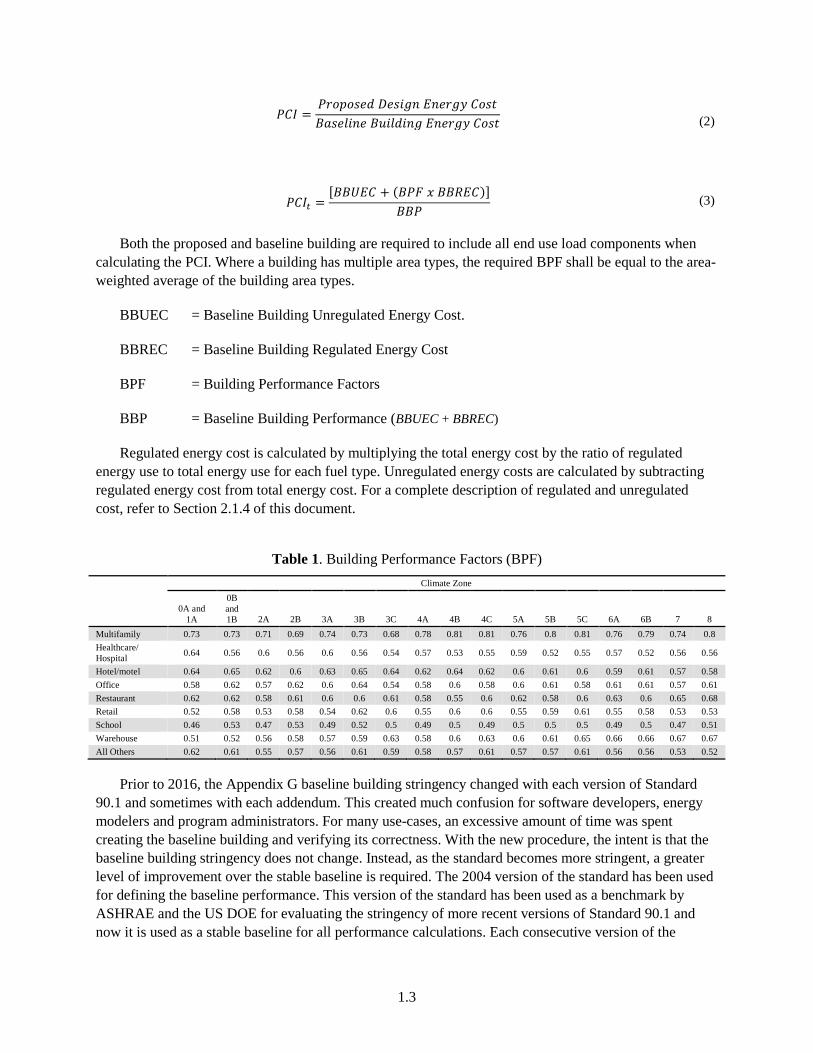
Both the proposed and baseline building are required to include all end use load components when calculating the PCI. Where a building has multiple area types, the required BPF shall be equal to the area-weighted average of the building area types.
BBUEC = Baseline Building Unregulated Energy Cost.
BBREC = Baseline Building Regulated Energy Cost
BPF = Building Performance Factors
BBP = Baseline Building Performance (BBUEC + BBREC)
Regulated energy cost is calculated by multiplying the total energy cost by the ratio of regulated energy use to total energy use for each fuel type. Unregulated energy costs are calculated by subtracting regulated energy cost from total energy cost. For a complete description of regulated and unregulated cost, refer to Section 2.1.4 of this document.
Table 1. Building Performance Factors (BPF)
Climate Zone
0A and 1A
0B and 1B 2A 2B 3A 3B 3C 4A 4B 4C 5A 5B 5C 6A 6B 7 8
Multifamily 0.73 0.73 0.71 0.69 0.74 0.73 0.68 0.78 0.81 0.81 0.76 0.8 0.81 0.76 0.79 0.74 0.8 Healthcare/ Hospital 0.64 0.56 0.6 0.56 0.6 0.56 0.54 0.57 0.53 0.55 0.59 0.52 0.55 0.57 0.52 0.56 0.56
Hotel/motel 0.64 0.65 0.62 0.6 0.63 0.65 0.64 0.62 0.64 0.62 0.6 0.61 0.6 0.59 0.61 0.57 0.58 Office 0.58 0.62 0.57 0.62 0.6 0.64 0.54 0.58 0.6 0.58 0.6 0.61 0.58 0.61 0.61 0.57 0.61 Restaurant 0.62 0.62 0.58 0.61 0.6 0.6 0.61 0.58 0.55 0.6 0.62 0.58 0.6 0.63 0.6 0.65 0.68 Retail 0.52 0.58 0.53 0.58 0.54 0.62 0.6 0.55 0.6 0.6 0.55 0.59 0.61 0.55 0.58 0.53 0.53 School 0.46 0.53 0.47 0.53 0.49 0.52 0.5 0.49 0.5 0.49 0.5 0.5 0.5 0.49 0.5 0.47 0.51 Warehouse 0.51 0.52 0.56 0.58 0.57 0.59 0.63 0.58 0.6 0.63 0.6 0.61 0.65 0.66 0.66 0.67 0.67 All Others 0.62 0.61 0.55 0.57 0.56 0.61 0.59 0.58 0.57 0.61 0.57 0.57 0.61 0.56 0.56 0.53 0.52
Prior to 2016, the Appendix G baseline building stringency changed with each version of Standard 90.1 and sometimes with each addendum. This created much confusion for software developers, energy modelers and program administrators. For many use-cases, an excessive amount of time was spent creating the baseline building and verifying its correctness. With the new procedure, the intent is that the baseline building stringency does not change. Instead, as the standard becomes more stringent, a greater level of improvement over the stable baseline is required. The 2004 version of the standard has been used for defining the baseline performance. This version of the standard has been used as a benchmark by ASHRAE and the US DOE for evaluating the stringency of more recent versions of Standard 90.1 and now it is used as a stable baseline for all performance calculations. Each consecutive version of the
1.4
Standard would update the target PCI without modifying the stringency of the baseline building requirements.
1.4 Organization
This document is organized into five chapters, as described below.
Table 2. Organization of the PRM-RM
Chapter Description 1.0 Overview The purpose, organization, content, and intent of the manual (this chapter). 2.0 General Modeling Procedures An overview of the modeling process, outlining the modeling rules and
assumptions that are implemented in the same way for both the baseline building and the proposed design, and procedures for determining system types and equipment sizes.
3.0 Building Descriptors Reference The acceptable range of inputs for the proposed design and a specification for the baseline building.
4.0 Energy Price Data Process for defining state average and custom utility rates. 5.0 Reporting Standard output reports required to be generated from a software tool to meet
Standard 90.1-2016 PRM reporting requirements.
This document references COMNET (COMNET 2017) for several appendices containing reference material that support definition of the baseline building. References appendices from the NACM can also be used for default assumptions for the proposed and baseline building (CEC 2016).
1.5 Type of Project Submittal
The type of project could be any one or combination of the following:
• New building
• Additions to an existing building
• Alterations of an existing building
Baseline for unmodified existing building systems or components is the same as the baseline for new systems and components except for vertical fenestration area in existing buildings, as described in Section 3.4.8. However, it is acceptable to predict performance using building models that exclude parts of the existing building, provided that all of the following conditions are met:
a. Work to be performed in excluded parts of the building shall meet the requirements of Sections 5 through 10 of Standard 90.1-2016.
b. Excluded parts of the building are served by HVAC systems that are entirely separate from those serving parts of the building that are included in the building model.
c. Design space temperature and HVAC system operating set points and schedules on either side of the boundary between included and excluded parts of the building are essentially the same.
2.5
d. If a declining block or similar utility rate is being used in the analysis, and the excluded and included parts of the building are on the same utility meter, the rate shall reflect the utility block or rate for the building plus the addition.
2.0 General Modeling Procedures
2.1 General Requirements for Data from the User
2.1.1 General
This document lists the building descriptors that are used in the simulation. Users must provide valid data for all descriptors that do not have defaults specified and that apply to parts of the building that must be modeled.
2.1.2 Definition of Building Descriptors
Building descriptors provide information about the proposed design and the baseline building. In this chapter, the building descriptors are discussed in the generic terms of engineering drawings and specifications. By using generic building descriptors, this manual avoids bias toward any particular energy simulation engine. The building descriptors in this chapter are compatible with commonly used simulation software.
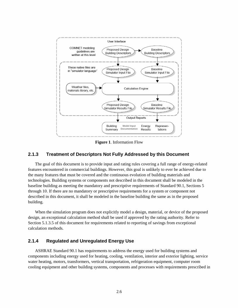
Each energy simulation program has its own way of accepting building information. EnergyPlus, for instance, uses a comma delimited data file called an IDF file. DOE-2 uses BDL (building design language) to accept information. It is the software’s responsibility to translate the generic terms used in this chapter into the “native language” of the simulation program. Figure 1 illustrates the flow of information.
2.6
Figure 1. Information Flow
2.1.3 Treatment of Descriptors Not Fully Addressed by this Document
The goal of this document is to provide input and rating rules covering a full range of energy-related features encountered in commercial buildings. However, this goal is unlikely to ever be achieved due to the many features that must be covered and the continuous evolution of building materials and technologies. Building systems or components not described in this document shall be modeled in the baseline building as meeting the mandatory and prescriptive requirements of Standard 90.1, Sections 5 through 10. If there are no mandatory or prescriptive requirements for a system or component not described in this document, it shall be modeled in the baseline building the same as in the proposed building.
When the simulation program does not explicitly model a design, material, or device of the proposed design, an exceptional calculation method shall be used if approved by the rating authority. Refer to Section 5.1.3.5 of this document for requirements related to reporting of savings from exceptional calculation methods.
2.1.4 Regulated and Unregulated Energy Use
ASHRAE Standard 90.1 has requirements to address the energy used for building systems and components including energy used for heating, cooling, ventilation, interior and exterior lighting, service water heating, motors, transformers, vertical transportation, refrigeration equipment, computer room cooling equipment and other building systems, components and processes with requirements prescribed in
Model Input Documentation
2.7
Standard 90.1 Sections 5 through 10. But there is a multitude of unregulated energy use within the building that is not addressed by the standard, including:
• All the things that are plugged into convenience outlets such as personal computers, printers, coffee machines, and refrigerators;
• Grills, ovens, fryers, steam trays, and other cooking equipment in restaurants and cafeterias;
• Compressed air systems in manufacturing and warehouse facilities; and
• Specialized equipment in laboratories, hospitals, and manufacturing plants.
• Non Refrigeration Related Process Loads – Energy consumed in the support a manufacturing, industrial, or commercial process other than serving commercial refrigeration equipment, conditioning spaces and maintaining comfort and amenities for the occupants of a building. For example:
o Computer equipment in the data center would be unregulated while the HVAC system used to condition the data center is regulated.
• If chiller/boiler is used to provide chilled water or hot water to meet process loads and are covered by conditions in Standard 90.1-2016 Table 6.8.1-3 and Table 6.8.1-6, then the baseline equipment used to model the chilled water and hot water should use the efficiency specified in Standard 90.1-2016 Table G3.5-3 and Table G3.5-6, else it should be modeled as same as proposed.
Energy modelers and software developers must be able to distinguish between regulated and unregulated energy use since this is an important factor in determining the PCI target for compliance with 90.1-2016. The target performance cost index (PCIt) assumes that the unregulated energy use is neutral for both the proposed design and the baseline building, and the procedure for determining PCIt has adjustments for the percent of unregulated energy.
2.2 Thermal Blocks, HVAC Zones, and Space Functions
2.2.1 Definitions
A space is a subcomponent of an HVAC zone that has values identified for lighting, outdoor air ventilation, occupancy, receptacle loads, and hot water consumption requirements. A space could be conditioned, semi-heated, or unconditioned. An HVAC zone may contain more than one space type.
A Heating Ventilation and Air Conditioning (HVAC) zone is a space or collection of spaces within a building having space conditioning requirements that are similar enough to be maintained with a single thermal controlling device. An HVAC zone is a thermal and not a geometric concept: spaces need not be contiguous to be combined within a single HVAC zone. However, daylighting requirements may prevent combining non-contiguous spaces into a single HVAC zone. If individual spaces are not modeled but combined into a zone, the space type breakdown (floor area of each space) should be provided.
A thermal block is a collection of one or more HVAC zones grouped together for simulation purposes. Spaces need not be contiguous to be combined within a single thermal block.
Similar HVAC zones can be combined into a single thermal block provided they
2.8
a. Are served by the same type of HVAC system
b. Consist of a similar distribution of space types
c. Have the same occupancy, equipment, lighting, and thermostat schedules and setpoints
d. Are adjacent to opaque walls only, or if adjacent to glazed walls, their orientation differs by less than 45°.
Residential spaces shall be modeled using at least one thermal block per dwelling unit, except that those units facing the same orientations may be combined into one thermal block. Corner units and units with roof or floor loads shall only be combined with units sharing these features.
Where the HVAC zones and systems have not yet been designed, thermal blocks shall be defined based on similar internal load densities, occupancy, lighting, thermal and space temperature schedules, and in combination with the following guidelines:
a. Separate thermal blocks shall be assumed for interior and perimeter spaces. Interior spaces shall be those located greater than 15 ft from an exterior wall. Perimeter spaces shall be those located within 15 ft of an exterior wall.
b. Separate thermal blocks shall be assumed for spaces adjacent to glazed exterior walls; a separate zone shall be provided for each orientation, except that orientations that differ by less than 45° may be considered the same orientation. Each zone shall include all floor area that is 15 ft or less from a glazed perimeter wall, except that floor area within 15 ft of glazed perimeter walls having more than one orientation shall be divided proportionately between zones.
c. Separate thermal blocks shall be assumed for spaces having floors that are in contact with the ground or exposed to ambient conditions from zones that do not share these features.
d. Floors with identical thermal blocks can be grouped for modeling purposes.
e. Separate thermal blocks shall be assumed for spaces having exterior ceiling or roof assemblies from zones that do not share these features.
For example, residential spaces should be modeled using one thermal block per unit. Where units are thermally similar, dwelling units or hotel rooms may be combined. Corner units and units with roof or floor loads shall only be combined with units sharing these features.
f. Plenums are spaces typically located above the ceiling and/or below the floor above used to transfer air, where lighting fixtures, pipes, ducts and other building services are often located. Plenums are often used as part of a building’s return air pathway. Because of the leakage through the ceiling (typically suspended with lay-in panels), the temperature of the plenum tracks the temperature of the space, except that it is generally warmer because of heat stratification and heat produced by lighting fixtures located at the ceiling or in the plenum.
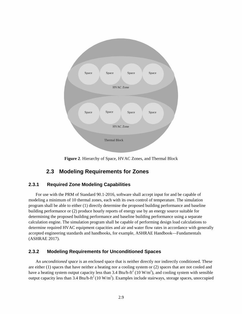
It is generally recommended that plenums be modeled as separate thermal blocks, but at the modeler’s discretion, they may be combined with conditioned space below for modeling simplicity. Figure 2 shows the hierarchy of spaces and HVAC zones.
2.9
Figure 2. Hierarchy of Space, HVAC Zones, and Thermal Block
2.3 Modeling Requirements for Zones
2.3.1 Required Zone Modeling Capabilities
For use with the PRM of Standard 90.1-2016, software shall accept input for and be capable of modeling a minimum of 10 thermal zones, each with its own control of temperature. The simulation program shall be able to either (1) directly determine the proposed building performance and baseline building performance or (2) produce hourly reports of energy use by an energy source suitable for determining the proposed building performance and baseline building performance using a separate calculation engine. The simulation program shall be capable of performing design load calculations to determine required HVAC equipment capacities and air and water flow rates in accordance with generally accepted engineering standards and handbooks, for example, ASHRAE Handbook—Fundamentals (ASHRAE 2017).
2.3.2 Modeling Requirements for Unconditioned Spaces
An unconditioned space is an enclosed space that is neither directly nor indirectly conditioned. These are either (1) spaces that have neither a heating nor a cooling system or (2) spaces that are not cooled and have a heating system output capacity less than 3.4 Btu/h-ft2 (10 W/m2), and cooling system with sensible output capacity less than 3.4 Btu/h-ft2 (10 W/m2). Examples include stairways, storage spaces, unoccupied
Space
Space
Space
Space
HVAC Zone
Space
Space
Space
HVAC Zone
Thermal Block
Space
2.10
adjacent tenant spaces, and attached sunspaces. Ventilated parking garages, attics, and crawlspaces are defined by Standard 90.1-2016 as unenclosed spaces and are not considered as unconditioned spaces. Modeling requirements for ventilated parking garages, attics, and crawlspaces are documented in the section below.
Unconditioned spaces shall be modeled if they are part of the permitted space. Permitted space includes all spaces in the building that are being analyzed for compliance with the use-case, which could be a beyond code program, a code compliance program or any other application which requires compliance with Standard 90.1-2016 PRM. All applicable envelope information shall be specified in a similar manner to conditioned space. If the unconditioned space is not a part of the permitted space, the space may be explicitly modeled or its impact on the permitted space may be approximated by modeling the space as outdoor space and turning off solar gains to the demising wall that separates the permitted space from the adjacent unconditioned space. The baseline envelope of conditioned, semi-heated, or plenum space adjacent to any other “unconditioned” enclosed space would be semi-exterior. Fenestration on these surfaces would be included in the fenestration area calculations for semi-exterior surfaces. For unconditioned spaces that are explicitly modeled, all internal gains and operational loads (occupants, water heating, receptacle, lighting and process loads) shall be modeled as designed if known or as specified in COMNET Appendix B (COMNET 2017) if unknown.
Return air plenums are considered indirectly conditioned spaces and shall be modeled with equipment, lighting power, and occupant loads at zero. Where recessed lights are used, heat from lights can be modeled to be transferred to the plenum.
Indirectly conditioned spaces can be either occupiable or not occupiable. For spaces that are not occupiable (such as plenums), lighting, receptacle, and occupant loads shall be zero. For indirectly conditioned spaces that are occupied, such as retail spaces, portions of restaurants etc., the lighting, receptacle and occupant loads would be as designed. Indirectly conditioned zones will not have thermostat setpoint schedules. The allocation of zones into conditioned, indirectly-conditioned, and unconditioned zones shall be the same in baseline and proposed building models.
Unconditioned spaces may not be located in the same thermal zone as conditioned spaces. Conditioned spaces and indirectly conditioned spaces may be located in the same zone; when this occurs, the indirectly conditioned spaces will assume the space temperature schedule of the conditioned space.
2.3.3 Modeling Requirements for Parking Garages, Attics, and Crawlspaces
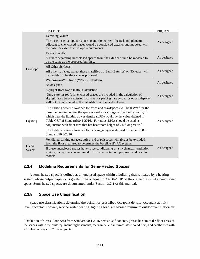
Space types such as ventilated parking garage, attics, and crawlspaces are defined by Standard 90.1-2016 as unenclosed spaces, and for the purposes of envelope requirements, envelope components adjacent to them are treated as exterior surfaces. Therefore, the following rules apply:
2.11
Baseline Proposed
Envelope
Demising Walls: The baseline envelope for spaces (conditioned, semi-heated, and plenum) adjacent to unenclosed spaces would be considered exterior and modeled with the baseline exterior envelope requirements.
As designed
Exterior Walls: Surfaces separating unenclosed spaces from the exterior would be modeled to be the same as the proposed building.
As designed
All Other Surfaces: All other surfaces, except those classified as ‘Semi-Exterior’ or ‘Exterior’ will be modeled to be the same as proposed.
As designed
Window-to-Wall Ratio (WWR) Calculation: As designed
As designed
Skylight Roof Ratio (SRR) Calculation: Only exterior roofs for enclosed spaces are included in the calculation of skylight area, hence exterior roof area for parking garages, attics or crawlspaces will not be considered in the calculation of the skylight area.
As designed
Lighting
The lighting power allowance for attics and crawlspaces will be 0 W/ft2 for the baseline building unless the space is used as a storage or mechanical room, in which case the lighting power density (LPD) would be the value defined in Table G3.7 of Standard 90.1-2016. . For attics, LPDs should be used in conjunction with floor area that has headroom height of 7.5 ft or greater.3 The lighting power allowance for parking garages is defined in Table G3.8 of Standard 90.1-2016.
As designed
HVAC System
Ventilated parking garages, attics, and crawlspaces will always be excluded from the floor area used to determine the baseline HVAC system.
As designed If these unenclosed spaces have space conditioning or a mechanical ventilation system, the systems are assumed to be the same in both proposed and baseline models.
2.3.4 Modeling Requirements for Semi-Heated Spaces
A semi-heated space is defined as an enclosed space within a building that is heated by a heating system whose output capacity is greater than or equal to 3.4 Btu/h·ft2 of floor area but is not a conditioned space. Semi-heated spaces are documented under Section 3.2.1 of this manual.
2.3.5 Space Use Classification
Space use classifications determine the default or prescribed occupant density, occupant activity level, receptacle power, service water heating, lighting load, area-based minimum outdoor ventilation air,
3 Definition of Gross Floor Area from Standard 90.1-2016 Section 3: floor area, gross: the sum of the floor areas of the spaces within the building, including basements, mezzanine and intermediate-floored tiers, and penthouses with a headroom height of 7.5 ft or greater.
2.12
daylighting setpoints, and operating schedules used in the analysis. Process loads and refrigeration loads are also provided for applicable space types. The user shall designate space use classifications that best match the uses for which the building or individual spaces within the building are being designed.
The user may override the default assumptions for some building descriptors dependent on the space use classification with supporting documentation. Details are provided in Section 3.3.1 of this manual.
2.3.5.1 Space Use Classification Considerations
Space function inputs and how they translate to thermal zone and HVAC system analysis assumptions are defined by the following rules:
• Schedule Group: 12 different schedule groups are defined in COMNET Appendix C (COMNET 2017) for the Standard 90.1-2016 PRM. Each schedule group defines building-specific hourly profiles for thermostat setpoints, HVAC system availability, occupancy, lighting, etc. The schedules of operation can be entered by the user or defaulted to the values defined in COMNET Appendix C (COMNET 2017).
• Space Functions: Each building space is assigned one space function. Design internal loads and other space function input assumptions, including the assigned schedule group described above, can be input by the user or can be defaulted to the values defined in COMNET Appendix B (COMNET 2017). This is discussed in Section 3.3 of this manual.
• HVAC Zones: The makeup of spaces in thermal zones shall match the proposed building design. If HVAC zones have not yet been designed, they shall be determined in accordance with Section 3.2.1. Where HVAC zones include different space types, peak internal loads and other design inputs for the HVAC zone are determined by weight-averaging the space function design inputs by floor area. Thermal zone schedules are based on the schedule group of the predominant space function (by floor area) included in the thermal zone
2.4 Unmet Load Hours
This manual uses the term unmet load hours (UMLH) as a criterion for sizing equipment, for qualifying natural ventilation systems, and for other purposes. . For a thermal zone, it represents the number of hours during a year when the HVAC system serving the thermal zone is unable to maintain the setpoint temperatures for heating and/or cooling. During periods of unmet loads, the space temperature drifts above the cooling setpoint or below the heating setpoint. A thermal zone is considered to have an unmet load hour if the space temperature is below the heating temperature setpoint or above the cooling temperature setpoint by more than 50% of the temperature control throttling range. Unmet load hours for the proposed design or baseline building designs shall not exceed 300 (of the 8760 hours simulated). Alternatively, unmet load hours exceeding these limits may be accepted at the discretion of the rating authority provided that sufficient justification is given indicating that the accuracy of the simulation is not significantly compromised by these unmet loads. One hour with unmet loads in one or more thermal zones counts as a single unmet load hour for the building
UMLH can occur because fans, airflows, coils, furnaces, air conditioners, or other equipment is undersized. UMLH can also occur due to user errors, including mismatches between the thermostat setpoint schedules and HVAC operating schedules, or from other input errors. It is the user’s
2.13
responsibility to address causes of UMLH in the proposed design. There can be many reasons for UMLH; the following list is a starting point to help identify the reasons:
• The thermostat schedules should agree with schedules of HVAC system operation, occupant schedules, miscellaneous equipment schedules, outside air ventilation schedules, and other schedules of operation that could affect the HVAC system’s ability to meet loads in the thermal block.
• The inputs for internal gains, occupants, and outside air ventilation should be reasonable and consistent with the intended operation of the building.
• The simulated operation of controls can be examined to determine if primary or secondary heating or cooling equipment (pumps, coils, boilers, etc.) is activated. The control scheme for secondary equipment should be verified.
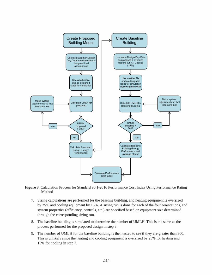
2.5 Calculation Procedures The general calculation procedure is illustrated in Figure 3 and explained in the steps below.
1. The process begins with a detailed description of the proposed design. Information is required to be provided in enough detail to enable an estimate of annual energy use for a typical weather year. This information includes the building envelope, the lighting systems, the HVAC systems, the water heating systems, and other important energy-using systems. This collection of information is referred to in this manual as building descriptors. Details on the building descriptors are provided in Chapter 2.
2. If the values of occupant density, equipment power density, ventilation rates, and water heating loads for the proposed building are not known, defaults based on the building type shall be used. Each building descriptor shall be either a user-defined input or the default value for that input where a default is available.
3. The next step is to simulate the proposed design to determine how well the heating and cooling loads are being satisfied. The indicator is the total number of UMLH. Test the number of UMLH and proceed only if the hours are less than or equal to 300 for the year of the proposed design simulation.
4. If the UMLH are greater than 300 for the year, then the user adjusts the proposed building simulation model to reduce the UMLH to less than or equal to 300. See Sections 2.4 and 2.6 for discussion on how UMLHs can be reduced.
5. If the UMLH are less than or equal to 300, then the final simulation is performed. If no changes are made in the model, the simulation from step 3 may be considered final. These calculations produce the results that are compared to the baseline building, which is calculated in steps 7 through 16.
6. The next steps relate to the creation of the baseline building model. The baseline building is created following the rules in this manual. It has the same floor area, number of floors, and spatial configuration as the proposed design; however, systems and components are modified to be in minimum compliance with Standard 90.1-2016 PRM. The HVAC systems for the baseline building are established according to rules in this manual and depend on the primary building activity (residential or non-residential), the floor area, and the number of stories. See Section 3.1.
2.14
Figure 3. Calculation Process for Standard 90.1-2016 Performance Cost Index Using Performance Rating Method
7. Sizing calculations are performed for the baseline building, and heating equipment is oversized by 25% and cooling equipment by 15%. A sizing run is done for each of the four orientations, and system properties (efficiency, controls, etc.) are specified based on equipment size determined through the corresponding sizing run.
8. The baseline building is simulated to determine the number of UMLH. This is the same as the process performed for the proposed design in step 3.
9. The number of UMLH for the baseline building is then tested to see if they are greater than 300. This is unlikely since the heating and cooling equipment is oversized by 25% for heating and 15% for cooling in step 7.
Calculate Performance Cost Index
Make system adjustments so that
loads are met
Create Baseline Building
Calculate Baseline Building Energy
Performance and average of four
Create Proposed Building Model
Use same Design Day Data as proposed + oversize Heating (25%), Cooling
(15%)
Use local weather Design Day Data and size with as-
designed load assumptions
Use weather file and as-designed
loads for simulation
Make system adjustments so that
loads are met Calculate UMLH for
proposed Calculate UMLH for Baseline Building
Use weather file and as-designed
loads for simulation (following the PRM
Calculate Proposed Design Energy Performance
UMLH proposed
> 300? UMLH
baseline > 300? Yes Yes
No No
2.15
10. If the UMLH are greater than 300, then steps need to be taken to reduce the unmet hours to less than or equal to 300. See Sections 2.4 and 2.6 for discussion on how UMLHs can be reduced.
11. Once the tests on UMLH are satisfied, the energy consumption of the baseline building is calculated. If the tests on unmet hours are satisfied the first time through, this step is the same as step 9.
12. The baseline building is rotated 90 degrees and modeled again. This is repeated for four orientations. Each time the building is rotated the equipment is resized. This step may be omitted if the building orientation is dictated by the site or if fenestration area on each orientation varies by less than 5%.
13. The baseline energy use for the baseline building is calculated as the average of the energy use for the four orientations.
14. Finally, the performance cost index is calculated as the ratio of the proposed design energy cost and baseline building energy cost.
The next two steps are followed if the PRM is being used for determination of compliance with Standard 90.1.
1. The PCIt is calculated in accordance with Section 1.3.
2. The PCI is compared to the PCIt to determine if the proposed building design is in compliance with Standard 90.1.
2.6 HVAC Capacity Requirements and Sizing
To ensure that the simulated space-conditioning loads are adequately met, adequate capacity must be available in each component of the HVAC system (e.g., supply-airflow rates, cooling coils, chillers, and cooling towers). If any component of the system is incapable of adequate performance, the simulation program will report UMLH, which need to be addressed following the steps in Section 2.5. Adequate capacities are required in the simulations of both the proposed design and the baseline building. If the equipment capacity is not sufficient to meet demands, then UMLH are evaluated at the building level by looking at the UMLH for each thermal zone being modeled. The subsections below describe the procedures that shall be followed to ensure that both the baseline and proposed building models are simulated with adequate space-conditioning capacities.
2.6.1 Specifying HVAC Capacities for the Proposed Design
If loads are not met for more than 300 hours, the software shall require the user to change the proposed design building description to bring the UMLH equal to or below 300. This process might not be automated by the software, in which case the user is required to modify the design model to bring the UMLH within acceptable limits. Two tests must be met:
• Space loads must be satisfied and space temperatures in all zones must be maintained within one half of the throttling range (1°F with a 2°F throttling range) of the scheduled heating or cooling thermostat setpoints. This criterion may be exceeded for no more than 300 hours for a typical year.
2.16
• System loads must be satisfied: Plant equipment must have adequate capacity to satisfy the HVAC system loads. This criterion may be exceeded for no more than 300 hours for a typical year.
Equipment sizes for the proposed design shall be entered into the model by the energy analyst and shall agree with the equipment sizes specified in the construction documents. When the simulations of these actual systems indicate that specified space conditions are not being adequately maintained in one or more thermal zone(s), the user shall be prompted to verify the model inputs to reduce the number of UMLHs.
2.6.2 Sizing Equipment in the Baseline Building
System coil capacities in the baseline building are automatically oversized by the program (25% for heating and 15% for cooling). Equipment is sized using design day data and weather files for the building location. These are discussed in Section 3.1.5 of this manual. The coil capacities shall be based on sizing runs for each orientation in accordance to Section 2.5 of this manual.
Oversizing would be carried out at the zone level, where the sizing parameters would be applied to the zone design coil loads, but not to the supply airflow. The system sizing calculations would sum the zone design airflow rates to obtain a system level airflow rate. The design conditions and the outdoor airflow rate would be used by the simulation program to calculate a design mixed air temperature. The temperature plus the design supply air temperatures (SATs) would allow for the calculation of system design heating and cooling capacities. The sizing option would be specified as “Coincident,” which specifies that the central system airflow rate will be sized on the sum of the coincident zone airflow rates. There would be no oversizing factor specified at the system level or the central plant level. Plant capacities shall be based on coincident loads.
For cooling sizing runs, schedules for internal loads including those used for infiltration, occupants, lighting, gas and electricity using equipment shall be equal to the highest value used in the annual simulation runs. For heating sizing runs, schedules for internal loads including those used for infiltration, occupants, lighting, gas and electricity using equipment shall be equal to the lowest value used in the annual simulation runs.
If the automatic oversizing percentage is not sufficient to meet demands, then UMLH are evaluated at the building level by looking at the UMLH for each thermal zone being modeled. The first step would be to determine if the UMLH are high (>300) for the proposed building design as well as the baseline building. If that is the case, the issue is usually related to fan operation, HVAC availability, and occupancy schedules where the HVAC system has an incorrectly specified schedule that makes it unavailable during occupied hours. Optimal start controls can also help eliminate UMLH during startup times. Since the same schedules are used for the baseline design, UMLH are seen in the baseline building as well. Other user inputs that could cause UMLH include incorrectly specified zone minimum airflows, which could result in unmet heating load hours. In this case, the software should notify the user and ask the user to verify schedules of operation. If a space is being conditioned via transfer air, it might be that the temperature of the transfer air is not sufficient to meet space conditioning requirements.
1. If this is not the case and UMLH are seen only with the baseline design, the software tool is required to incrementally increase system airflows and equipment capacities, following the steps outlined below.
2.17
a. In the case where UMLH for cooling are a bigger problem, the equipment in the baseline building model is resized by first increasing the design airflow of all zones with significant UMLH (greater than 150 for an individual zone) by 10%, increasing the design airflow of all zones with some UMLH (between 50 and 150) by 5%. Then, the equipment capacity for the system(s) serving the affected zones is increased to handle the increased zone loads. For the central plant, the chiller(s) and towers are resized proportionally to handle the increased system loads.
b. In the case where UMLH for heating are a bigger problem, the same procedure is followed, with zone airflows resized first, then heating secondary equipment capacity and then boiler capacity as necessary. The capacity of the boiler or furnace shall be increased in proportion to capacities of coils required to meet the increased airflows at the baseline supply air. For heat pumps, the capacity of the coil is increased so that the additional load is not met by auxiliary heat.
2.6.3 Proposed Design with No HVAC Equipment
2.6.3.1 No HVAC System Intended
Standard 90.1-2016 PRM doesn’t address buildings that are intended to have no HVAC system. Portions of a building with no heating and cooling system shall be simulated to be unconditioned for the baseline as well.
2.6.3.2 No HVAC System Designed
When the PRM is applied to buildings for which systems have not been designed, such as core and shell office buildings, the systems in the proposed design must be the same type as those in the baseline building and comply with, but not exceed the requirements of Standard 90.1-2016 Section 6.
Spaces that are cooled but not heated, are required to be simulated with heating. Spaces that are heated but not cooled are required to be simulated with a cooling system, unless they qualify as heated only spaces in accordance with Section 3.1.1.1(d).
3.1
3.0 Building Descriptors Reference
3.1 Overview
This chapter specifies the rules that apply to the proposed design and to the baseline building for each building descriptor.
3.1.1 HVAC System Map
The HVAC system in the baseline building depends on the primary building activity, the number of floors, conditioned floor area and climate zone. Details about these systems are provided in subsequent sections.
For many of the building descriptors there is a one-to-one relationship between the proposed design and the baseline building; for example, every wall in the proposed design has a corresponding wall in the baseline building. However, for HVAC systems, this one-to-one relationship generally does not hold. There may be the different number of HVAC systems serving the proposed design compared to the baseline building, and equipment such as cooling towers, circulation pumps, etc. may be present in the baseline but not proposed design.
The HVAC system in the baseline building shall be selected from Table 3, HVAC System Map, and be based on building type, number of floors, conditioned floor area, and climate zone. The selected system shall conform to the descriptions in Table 4, HVAC System Descriptions.
For systems 1, 2, 3, 4, 9, 10, 11, 12, and 13, each thermal zone shall be modeled with its own HVAC system. For systems 5, 6, 7, and 8, each floor shall be modeled with a separate HVAC system. Floors with identical thermal zones can be grouped for modeling purposes.
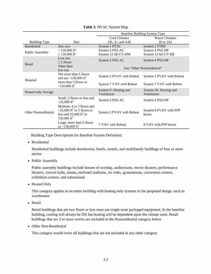
3.2
Table 3. HVAC System Map
Building Type Size
Baseline Building System Type Cool Climates
(3b, 3c, and 4-8) Warm Climates
(0 to 3A) Residential Any size System 1 PTAC System 2 PTHP
Public Assembly < 120,000 ft² System 3 PSZ-AC System 4 PSZ-HP ≥ 120,000 ft² System 12 SZ-CV-HW System 13 SZ-CV-ER
Retail
Low rise ≤ 2 floors System 3 PSZ-AC System 4 PSZ-HP
Other than low rise Use “Other Nonresidential”
Hospital
Not more than 5 floors and not >150,000 ft2 System 5 PVAV with Reheat System 5 PVAV with Reheat
more than 5 floors or >150,000 ft2 System 7 VAV with Reheat System 7 VAV with Reheat
Heated-only Storage System 9- Heating and Ventilation
System 10- Heating and Ventilation
Other Nonresidential
Small, 3 floors or less and <25,000 ft2 System 3 PSZ-AC System 4 PSZ-HP
Medium, 4 or 5 floors and <25,000 ft2 or 5 floors or less and 25,000 ft2 to 150,000 ft2
System 5 PVAV with Reheat System 6 PVAV with PFP boxes
Large, more than 5 floors or >150,000 ft2 7 VAV with Reheat 8 VAV with PFP boxes
Building Type Descriptions for Baseline System Definition:
• Residential
Residential buildings include dormitories, hotels, motels, and multifamily buildings of four or more stories
• Public Assembly
Public assembly buildings include houses of worship, auditoriums, movie theaters, performance theaters, concert halls, arenas, enclosed stadiums, ice rinks, gymnasiums, convention centers, exhibition centers, and natatoriums
• Heated Only
This category applies to an entire building with heating only systems in the proposed design, such as warehouses
• Retail
Retail buildings that are two floors or less must use single-zone packaged equipment. In the baseline building, cooling will always be DX but heating will be dependent upon the climate zone. Retail buildings that are 3 or more stories are included in the Nonresidential category below
• Other Non-Residential
This category would cover all buildings that are not included in any other category
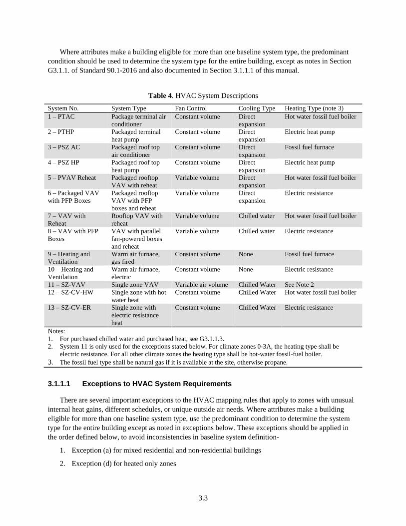
3.3
Where attributes make a building eligible for more than one baseline system type, the predominant condition should be used to determine the system type for the entire building, except as notes in Section G3.1.1. of Standard 90.1-2016 and also documented in Section 3.1.1.1 of this manual.
Table 4. HVAC System Descriptions
System No. System Type Fan Control Cooling Type Heating Type (note 3) 1 – PTAC Package terminal air
conditioner Constant volume Direct
expansion Hot water fossil fuel boiler
2 – PTHP Packaged terminal heat pump
Constant volume Direct expansion
Electric heat pump
3 – PSZ AC Packaged roof top air conditioner
Constant volume Direct expansion
Fossil fuel furnace
4 – PSZ HP Packaged roof top heat pump
Constant volume Direct expansion
Electric heat pump
5 – PVAV Reheat Packaged rooftop VAV with reheat
Variable volume Direct expansion
Hot water fossil fuel boiler
6 – Packaged VAV with PFP Boxes
Packaged rooftop VAV with PFP boxes and reheat
Variable volume Direct expansion
Electric resistance
7 – VAV with Reheat
Rooftop VAV with reheat
Variable volume Chilled water Hot water fossil fuel boiler
8 – VAV with PFP Boxes
VAV with parallel fan-powered boxes and reheat
Variable volume Chilled water Electric resistance
9 – Heating and Ventilation
Warm air furnace, gas fired
Constant volume None Fossil fuel furnace
10 – Heating and Ventilation
Warm air furnace, electric
Constant volume None Electric resistance
11 – SZ-VAV Single zone VAV Variable air volume Chilled Water See Note 2 12 – SZ-CV-HW Single zone with hot
water heat Constant volume Chilled Water Hot water fossil fuel boiler
13 – SZ-CV-ER Single zone with electric resistance heat
Constant volume Chilled Water Electric resistance
Notes: 1. For purchased chilled water and purchased heat, see G3.1.1.3. 2. System 11 is only used for the exceptions stated below. For climate zones 0-3A, the heating type shall be
electric resistance. For all other climate zones the heating type shall be hot-water fossil-fuel boiler. 3. The fossil fuel type shall be natural gas if it is available at the site, otherwise propane.
3.1.1.1 Exceptions to HVAC System Requirements
There are several important exceptions to the HVAC mapping rules that apply to zones with unusual internal heat gains, different schedules, or unique outside air needs. Where attributes make a building eligible for more than one baseline system type, use the predominant condition to determine the system type for the entire building except as noted in exceptions below. These exceptions should be applied in the order defined below, to avoid inconsistencies in baseline system definition-
1. Exception (a) for mixed residential and non-residential buildings
2. Exception (d) for heated only zones
3.4
3. Exception (e) for baseline system 9 and 10
4. Exception (f) for computer rooms
5. Exception (c) for laboratory spaces
6. Exception (b) for internal loads
a. Mixed Residential and Non-Residential Buildings:
The baseline HVAC system must be determined separately for buildings with both residential and non-residential zones. Additional system type(s) are required to be used if the non-predominant conditions (use type) apply to more than 20,000 ft2 of conditioned floor area. Residential building types include dormitory, hotel, motel, and multifamily. Residential space types include guest rooms, living quarters, private living space, and sleeping quarters. Other building and space types including common areas associated with residential buildings are considered nonresidential.
b. Internal Loads:
This exception is triggered for zones with peak thermal loads (excluding ventilation or envelope loads) that differ by more than 10 Btu/h-ft2 (31.5 W/m2) from the average of other zones served by the system or when the weekly operating hours of the HVAC system are different by more than 40 equivalent full load hours (EFLH) from other spaces served by the system. A full load hour is an hour during which the zone is occupied and supply and return fans operate continuously. The baseline system for such spaces would be system type 3 or 4, depending on the heating source for the main building. This exception does not apply to computer rooms, see (f) below for the exception related to computer rooms.
When multiple proposed systems with schedules varying for less than 40 hours are combined into a single baseline system as a whole floor variable air volume (VAV), the baseline system fan schedule is defined to include the earliest start hour and latest end hour, so that all spaces are designated to have HVAC system availability. Section 3.6.2.1 has more details regarding HVAC availability.
This exception doesn’t apply to computer rooms (see f. below).
The process for calculating internal loads for spaces is defined below-
Calculate the area-weighted average (Btu/ft2 or EFLH) for all the zones that would be served by a single system.
Find the zone whose value is most different from the area-weighted average.
a. If the difference is more than 10 Btu/ft2 or 40 hrs, remove that zone from the list and repeat steps with the reduced list. The zone should then be assigned system 3 or 4 depending on the heating source for the main building.
b. If the difference is less than 10 Btu/ft2 or 40 hr., then none of the zones on the system qualify for the internal loads exception.
Example 1: For a floor with zones with peak thermal loads specified as 6 Btu/h-ft2, 14 Btu/h-ft2, 24 Btu/h-ft2, and 34 Btu/h-ft2, the average of all zones is 19.5 Btu/h- ft2. Zone 4 would be subject to the exception since its peak thermal loads differ by more than 10 Btu/h-ft2 and the baseline system for this space would be system type 3 or 4 (depending on building heating source).Zone 4 would then be removed from the list and the average would be calculated again. The average thermal loads for the
3.5
three zones are now 14.67 Btu/h-ft2. All three zones have peak thermal loads differing by less than 10 Btu/h-ft2 and would hence stay on the same baseline system.
Example 2: An office building with baseline system 5 has the following thermal blocks on one floor:
Thermal Block A: Zones with predominantly office occupancy, to be occupied 50 hours per week;
Thermal Block B: Zones for security service, to be occupied 24/7 (168 hours per week);
Thermal Block C: Zones for help desk, to be occupied 80 hours per week.
Following the methodology outlined above, the average EFLHs for these 3 thermal blocks is 99.3. Since the difference from the average is greater than 40, Thermal Block B would be modeled with baseline system 3 and the average EFLHs would be calculated again. The average for Thermal Block A and Thermal Block C is 65 hours/week, hence both of these block would remain on the same baseline system.
Example 3: An office building with baseline system 5 has the following thermal zones on one floor:
Zone A: Occupied 25 hours per week;
Zone B: Occupied 30 hours per week;
Zone C: Occupied 35 hours per week;
Zone D: Occupied 80 hours per week;
Following the methodology outlined above, the average EFLHs for these 3 thermal blocks is 42.5 hours/week. Since the difference from the average is not greater than 40 for any zone, all zones would remain on the same baseline HVAC system.
c. Laboratory Spaces:
All zones with laboratory spaces in a building having a total laboratory exhaust rate greater than 15,000 cfm, use a single system of type 5 or 7 serving only those spaces. .The baseline system serving laboratory spaces shall be system 5 (PVAV with hot water reheat) or 7 (VAV with hot water reheat) depending on the size of the building. If the building is more than 5 floors or >150,000 ft2 use system 7. Otherwise, use system 5. The lab exhaust fan shall be modeled as constant horsepower reflecting constant volume stack discharge with outdoor air bypass. Heated only Zones:
d. Heated Only Zones Thermal zones designed with heating only systems in the proposed design, serving storage rooms, stairwells, vestibules, electrical/mechanical rooms, and restrooms not exhausting or transferring air from mechanically cooled thermal zones in the proposed design shall use system type 9 or 10 in the baseline building design. If a space type doesn’t fall in the list of “storage, stairwells, vestibules, electrical/mechanical rooms or restrooms,” then, despite being heated only, it would be modeled as heated and cooled. This rule applies even if the total area of such zones is below 20,000 ft2.
e. Baseline System 9, 10:
If the baseline HVAC system type is 9 or 10, all zones that are mechanically cooled in the proposed building design shall be assigned to a separate baseline system determined according to Table 3 by using the climate zone and floor area of the mechanically cooled zones. This rule applies even if the total area of such zones is below 20,000 ft2.
3.6
f. Computer Rooms:
Standard 90.1-2016 defines computer rooms as a room whose primary function is to house equipment for the processing and storage of electronic data and that has a design electronic data equipment power density exceeding 20 W/ft2 of conditioned floor area. This exception would also apply to server closets or telecom equipment closets if these requirements are met.
All zones with computer rooms would be modeled with systems 3 or 4 with the exception of-
i. Computer rooms in buildings with a total computer room peak cooling load>3,000,000 Btu/h
ii. Computer rooms in buildings with a total computer room peak cooling load>600,000 Btu/h where the baseline HVAC system type is 7 or 8.
Computer rooms meeting either of these two exceptions will use system 11 with the heating source determined by climate zone as described in footnote 2 to Table 4.
These special systems serve just the spaces that trigger the exceptions. The rest of the building/floor is served by the baseline building HVAC system as indicated in Table 3.
3.1.1.2 Process for Determining the Baseline System
This section provides guidance for determining the baseline HVAC system for a proposed design to address all requirements and exceptions specified in Section 3.1.1.
Step 1: Determine Predominant Building Type
The building type for use in Table 3 is determined by the “predominant occupancy” type. The predominant occupancy is defined as the occupancy with the greatest conditioned floor area (CFA) and other occupancy types are defined as the “non-predominant occupancy”. The building types include:
a. Residential
b. Public Assembly
c. Retail
d. Hospital
e. Heated-Only Storage
f. Other Non-Residential
Once the building type is determined based on the predominant occupancy as described above, the appropriate baseline system is chosen from Table 3 based on:
a. Number of floors (including floors above grade and below grade but not including floors solely devoted to parking).
b. Gross conditioned floor area (CFA).
c. Climate zone
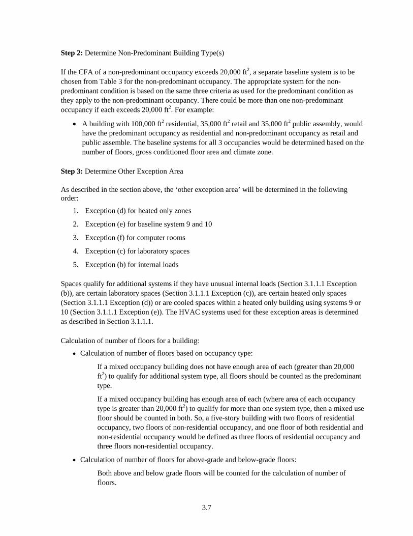
3.7
Step 2: Determine Non-Predominant Building Type(s)
If the CFA of a non-predominant occupancy exceeds 20,000 ft2, a separate baseline system is to be chosen from Table 3 for the non-predominant occupancy. The appropriate system for the non-predominant condition is based on the same three criteria as used for the predominant condition as they apply to the non-predominant occupancy. There could be more than one non-predominant occupancy if each exceeds 20,000 ft2. For example:
• A building with 100,000 ft2 residential, 35,000 ft2 retail and 35,000 ft2 public assembly, would have the predominant occupancy as residential and non-predominant occupancy as retail and public assemble. The baseline systems for all 3 occupancies would be determined based on the number of floors, gross conditioned floor area and climate zone.
Step 3: Determine Other Exception Area
As described in the section above, the ‘other exception area’ will be determined in the following order:
1. Exception (d) for heated only zones
2. Exception (e) for baseline system 9 and 10
3. Exception (f) for computer rooms
4. Exception (c) for laboratory spaces
5. Exception (b) for internal loads
Spaces qualify for additional systems if they have unusual internal loads (Section 3.1.1.1 Exception (b)), are certain laboratory spaces (Section 3.1.1.1 Exception (c)), are certain heated only spaces (Section 3.1.1.1 Exception (d)) or are cooled spaces within a heated only building using systems 9 or 10 (Section 3.1.1.1 Exception (e)). The HVAC systems used for these exception areas is determined as described in Section 3.1.1.1.
Calculation of number of floors for a building:
• Calculation of number of floors based on occupancy type:
If a mixed occupancy building does not have enough area of each (greater than 20,000 ft2) to qualify for additional system type, all floors should be counted as the predominant type.
If a mixed occupancy building has enough area of each (where area of each occupancy type is greater than 20,000 ft2) to qualify for more than one system type, then a mixed use floor should be counted in both. So, a five-story building with two floors of residential occupancy, two floors of non-residential occupancy, and one floor of both residential and non-residential occupancy would be defined as three floors of residential occupancy and three floors non-residential occupancy.
• Calculation of number of floors for above-grade and below-grade floors:
Both above and below grade floors will be counted for the calculation of number of floors.
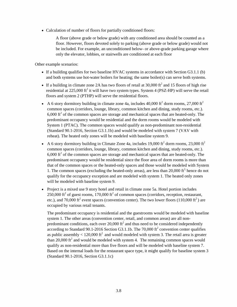
3.8
• Calculation of number of floors for partially conditioned floors:
A floor (above grade or below grade) with any conditioned area should be counted as a floor. However, floors devoted solely to parking (above grade or below grade) would not be included. For example, an unconditioned below- or above-grade parking garage where only the elevator, lobbies, or stairwells are conditioned at each floor
Other example scenarios:
• If a building qualifies for two baseline HVAC systems in accordance with Section G3.1.1 (b) and both systems use hot-water boilers for heating; the same boiler(s) can serve both systems.
• If a building in climate zone 2A has two floors of retail at 30,000 ft2 and 15 floors of high rise residential at 225,000 ft2 it will have two system types. System 4 (PSZ-HP) will serve the retail floors and system 2 (PTHP) will serve the residential floors.
• A 6 story dormitory building in climate zone 4a, includes 40,000 ft2 dorm rooms, 27,000 ft2 common spaces (corridors, lounge, library, common kitchen and dining, study rooms, etc.). 6,000 ft2 of the common spaces are storage and mechanical spaces that are heated-only. The predominant occupancy would be residential and the dorm rooms would be modeled with System 1 (PTAC). The common spaces would qualify as non-predominant non-residential (Standard 90.1-2016, Section G3.1.1b) and would be modeled with system 7 (VAV with reheat). The heated only zones will be modeled with baseline system 9.
• A 6 story dormitory building in Climate Zone 4a, includes 19,000 ft2 dorm rooms, 23,000 ft2 common spaces (corridors, lounge, library, common kitchen and dining, study rooms, etc.). 6,000 ft2 of the common spaces are storage and mechanical spaces that are heated-only. The predominant occupancy would be residential since the floor area of dorm rooms is more than that of the common spaces or the heated-only spaces and those would be modeled with System 1. The common spaces (excluding the heated-only areas), are less than 20,000 ft2, hence do not qualify for the occupancy exception and are modeled with system 1. The heated only zones will be modeled with baseline system 9.
• Project is a mixed use 9 story hotel and retail in climate zone 5a. Hotel portion includes 250,000 ft2 of guest rooms, 170,000 ft2 of common spaces (corridors, reception, restaurant, etc.), and 70,000 ft2 event spaces (convention center). The two lower floors (110,000 ft2 ) are occupied by various retail tenants.
The predominant occupancy is residential and the guestrooms would be modeled with baseline system 1. The other areas (convention center, retail, and common areas) are all non-predominant conditions, each over 20,000 ft2 and thus need to be considered independently according to Standard 90.1-2016 Section G3.1.1b. The 70,000 ft2 convention center qualifies as public assembly < 120,000 ft2 and would modeled with system 3. The retail area is greater than 20,000 ft2 and would be modeled with system 4. The remaining common spaces would qualify as non-residential more than five floors and will be modeled with baseline system 7. Based on the internal loads for the restaurant space type, it might qualify for baseline system 3 (Standard 90.1-2016, Section G3.1.1c)
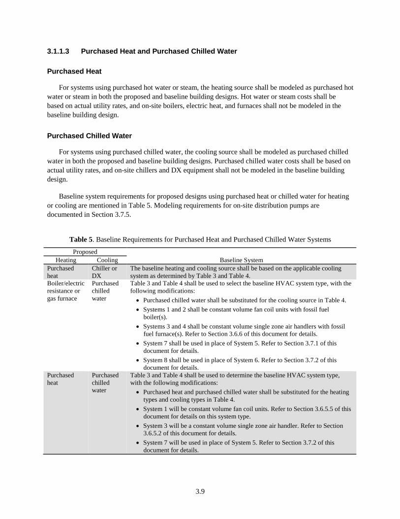
3.9
3.1.1.3 Purchased Heat and Purchased Chilled Water
Purchased Heat
For systems using purchased hot water or steam, the heating source shall be modeled as purchased hot water or steam in both the proposed and baseline building designs. Hot water or steam costs shall be based on actual utility rates, and on-site boilers, electric heat, and furnaces shall not be modeled in the baseline building design.
Purchased Chilled Water
For systems using purchased chilled water, the cooling source shall be modeled as purchased chilled water in both the proposed and baseline building designs. Purchased chilled water costs shall be based on actual utility rates, and on-site chillers and DX equipment shall not be modeled in the baseline building design.
Baseline system requirements for proposed designs using purchased heat or chilled water for heating or cooling are mentioned in Table 5. Modeling requirements for on-site distribution pumps are documented in Section 3.7.5.
Table 5. Baseline Requirements for Purchased Heat and Purchased Chilled Water Systems
Proposed Baseline System Heating Cooling
Purchased heat
Chiller or DX
The baseline heating and cooling source shall be based on the applicable cooling system as determined by Table 3 and Table 4.
Boiler/electric resistance or gas furnace
Purchased chilled water
Table 3 and Table 4 shall be used to select the baseline HVAC system type, with the following modifications:
• Purchased chilled water shall be substituted for the cooling source in Table 4. • Systems 1 and 2 shall be constant volume fan coil units with fossil fuel
boiler(s). • Systems 3 and 4 shall be constant volume single zone air handlers with fossil
fuel furnace(s). Refer to Section 3.6.6 of this document for details. • System 7 shall be used in place of System 5. Refer to Section 3.7.1 of this
document for details. • System 8 shall be used in place of System 6. Refer to Section 3.7.2 of this
document for details. Purchased heat
Purchased chilled water
Table 3 and Table 4 shall be used to determine the baseline HVAC system type, with the following modifications:
• Purchased heat and purchased chilled water shall be substituted for the heating types and cooling types in Table 4.
• System 1 will be constant volume fan coil units. Refer to Section 3.6.5.5 of this document for details on this system type.
• System 3 will be a constant volume single zone air handler. Refer to Section 3.6.5.2 of this document for details.
• System 7 will be used in place of System 5. Refer to Section 3.7.2 of this document for details.
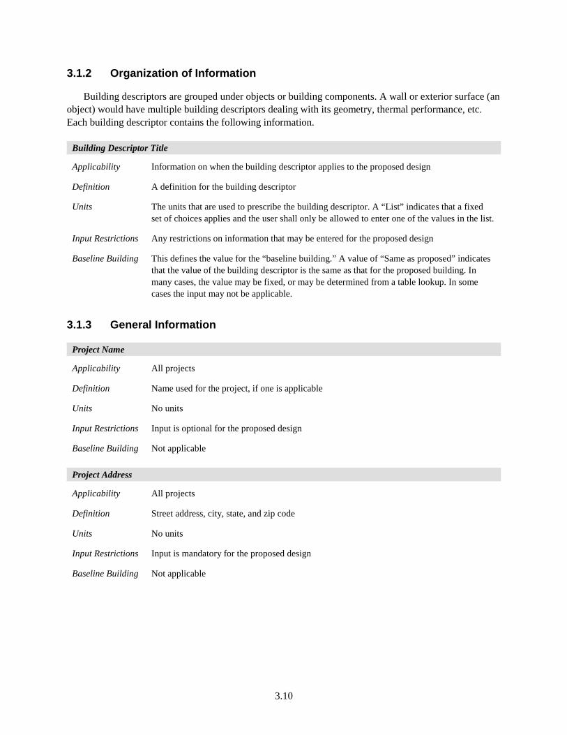
3.10
3.1.2 Organization of Information
Building descriptors are grouped under objects or building components. A wall or exterior surface (an object) would have multiple building descriptors dealing with its geometry, thermal performance, etc. Each building descriptor contains the following information.
Building Descriptor Title
Applicability Information on when the building descriptor applies to the proposed design
Definition A definition for the building descriptor
Units The units that are used to prescribe the building descriptor. A “List” indicates that a fixed set of choices applies and the user shall only be allowed to enter one of the values in the list.
Input Restrictions Any restrictions on information that may be entered for the proposed design
Baseline Building This defines the value for the “baseline building.” A value of “Same as proposed” indicates that the value of the building descriptor is the same as that for the proposed building. In many cases, the value may be fixed, or may be determined from a table lookup. In some cases the input may not be applicable.
3.1.3 General Information
Project Name
Applicability All projects
Definition Name used for the project, if one is applicable
Units No units
Input Restrictions Input is optional for the proposed design
Baseline Building Not applicable
Project Address
Applicability All projects
Definition Street address, city, state, and zip code
Units No units
Input Restrictions Input is mandatory for the proposed design
Baseline Building Not applicable
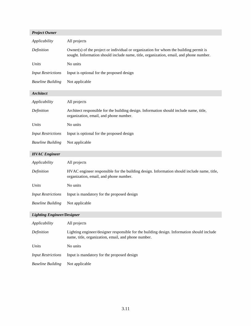
3.11
Project Owner
Applicability All projects
Definition Owner(s) of the project or individual or organization for whom the building permit is sought. Information should include name, title, organization, email, and phone number.
Units No units
Input Restrictions Input is optional for the proposed design
Baseline Building Not applicable
Architect
Applicability All projects
Definition Architect responsible for the building design. Information should include name, title, organization, email, and phone number.
Units No units
Input Restrictions Input is optional for the proposed design
Baseline Building Not applicable
HVAC Engineer
Applicability All projects
Definition HVAC engineer responsible for the building design. Information should include name, title, organization, email, and phone number.
Units No units
Input Restrictions Input is mandatory for the proposed design
Baseline Building Not applicable
Lighting Engineer/Designer
Applicability All projects
Definition Lighting engineer/designer responsible for the building design. Information should include name, title, organization, email, and phone number.
Units No units
Input Restrictions Input is mandatory for the proposed design
Baseline Building Not applicable
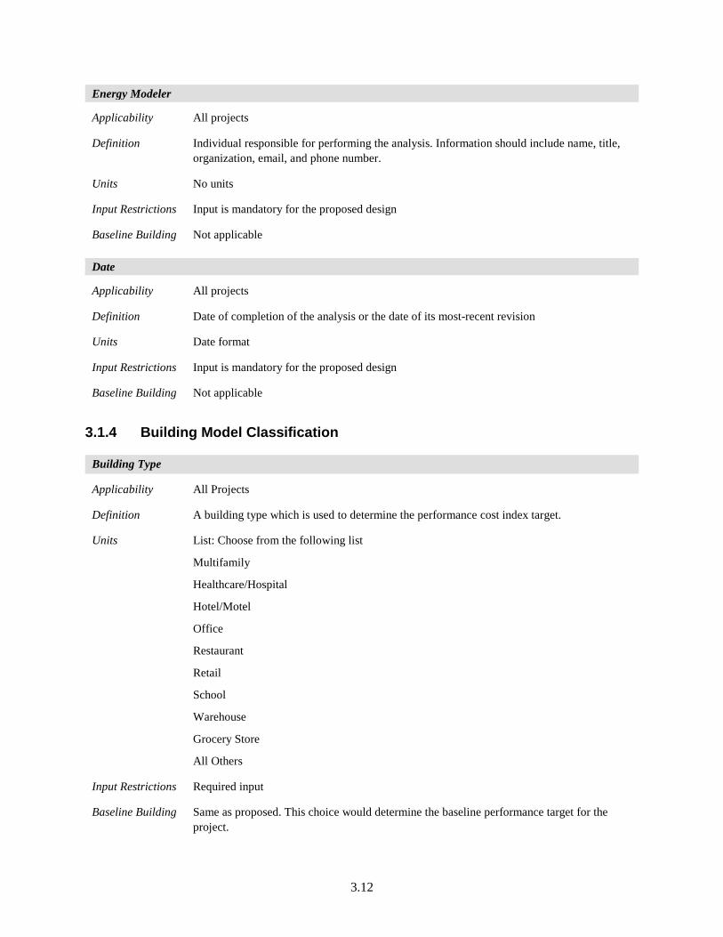
3.12
Energy Modeler
Applicability All projects
Definition Individual responsible for performing the analysis. Information should include name, title, organization, email, and phone number.
Units No units
Input Restrictions Input is mandatory for the proposed design
Baseline Building Not applicable
Date
Applicability All projects
Definition Date of completion of the analysis or the date of its most-recent revision
Units Date format
Input Restrictions Input is mandatory for the proposed design
Baseline Building Not applicable
3.1.4 Building Model Classification
Building Type
Applicability All Projects
Definition A building type which is used to determine the performance cost index target.
Units List: Choose from the following list
Multifamily
Healthcare/Hospital
Hotel/Motel
Office
Restaurant
Retail
School
Warehouse
Grocery Store
All Others
Input Restrictions Required input
Baseline Building Same as proposed. This choice would determine the baseline performance target for the project.
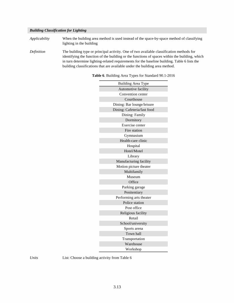
3.13
Building Classification for Lighting
Applicability When the building area method is used instead of the space-by-space method of classifying lighting in the building
Definition The building type or principal activity. One of two available classification methods for identifying the function of the building or the functions of spaces within the building, which in turn determine lighting-related requirements for the baseline building. Table 6 lists the building classifications that are available under the building area method.
Table 6. Building Area Types for Standard 90.1-2016
Building Area Type Automotive facility Convention center
Courthouse Dining: Bar lounge/leisure Dining: Cafeteria/fast food
Dining: Family Dormitory
Exercise center Fire station Gymnasium
Health-care clinic Hospital
Hotel/Motel Library
Manufacturing facility Motion picture theater
Multifamily Museum Office
Parking garage Penitentiary
Performing arts theater Police station
Post office Religious facility
Retail School/university
Sports arena Town hall
Transportation Warehouse Workshop
Units List: Choose a building activity from Table 6
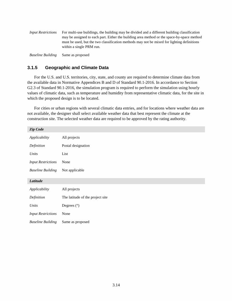
3.14
Input Restrictions For multi-use buildings, the building may be divided and a different building classification may be assigned to each part. Either the building area method or the space-by-space method must be used, but the two classification methods may not be mixed for lighting definitions within a single PRM run.
Baseline Building Same as proposed
3.1.5 Geographic and Climate Data
For the U.S. and U.S. territories, city, state, and county are required to determine climate data from the available data in Normative Appendices B and D of Standard 90.1-2016. In accordance to Section G2.3 of Standard 90.1-2016, the simulation program is required to perform the simulation using hourly values of climatic data, such as temperature and humidity from representative climatic data, for the site in which the proposed design is to be located.
For cities or urban regions with several climatic data entries, and for locations where weather data are not available, the designer shall select available weather data that best represent the climate at the construction site. The selected weather data are required to be approved by the rating authority.
Zip Code
Applicability All projects
Definition Postal designation
Units List
Input Restrictions None
Baseline Building Not applicable
Latitude
Applicability All projects
Definition The latitude of the project site
Units Degrees (°)
Input Restrictions None
Baseline Building Same as proposed
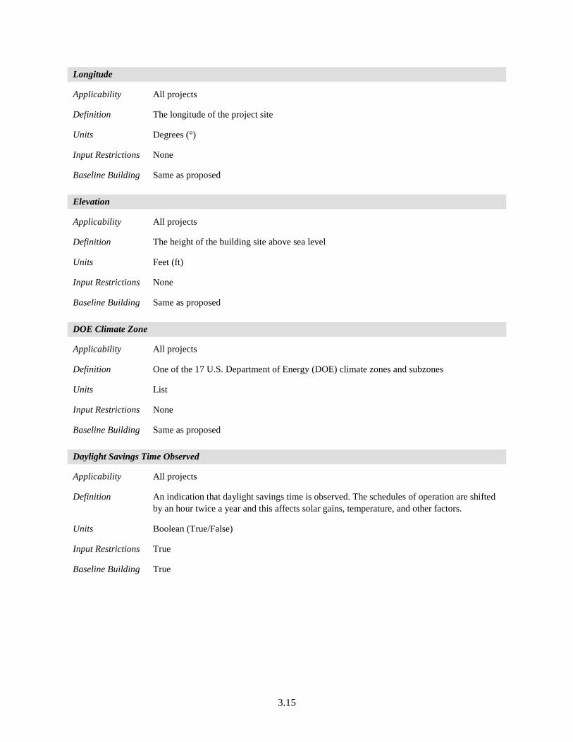
3.15
Longitude
Applicability All projects
Definition The longitude of the project site
Units Degrees (°)
Input Restrictions None
Baseline Building Same as proposed
Elevation
Applicability All projects
Definition The height of the building site above sea level
Units Feet (ft)
Input Restrictions None
Baseline Building Same as proposed
DOE Climate Zone
Applicability All projects
Definition One of the 17 U.S. Department of Energy (DOE) climate zones and subzones
Units List
Input Restrictions None
Baseline Building Same as proposed
Daylight Savings Time Observed
Applicability All projects
Definition An indication that daylight savings time is observed. The schedules of operation are shifted by an hour twice a year and this affects solar gains, temperature, and other factors.
Units Boolean (True/False)
Input Restrictions True
Baseline Building True
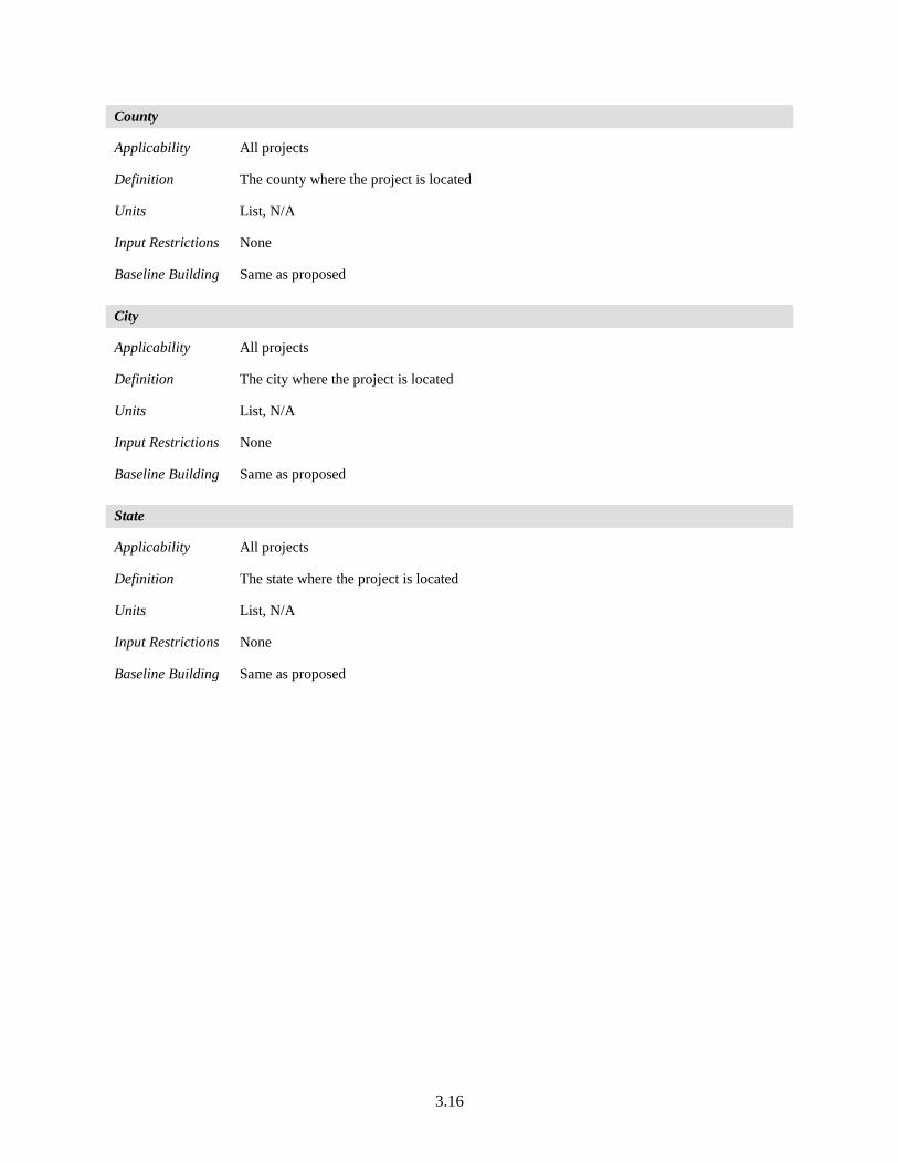
3.16
County
Applicability All projects
Definition The county where the project is located
Units List, N/A
Input Restrictions None
Baseline Building Same as proposed
City
Applicability All projects
Definition The city where the project is located
Units List, N/A
Input Restrictions None
Baseline Building Same as proposed
State
Applicability All projects
Definition The state where the project is located
Units List, N/A
Input Restrictions None
Baseline Building Same as proposed
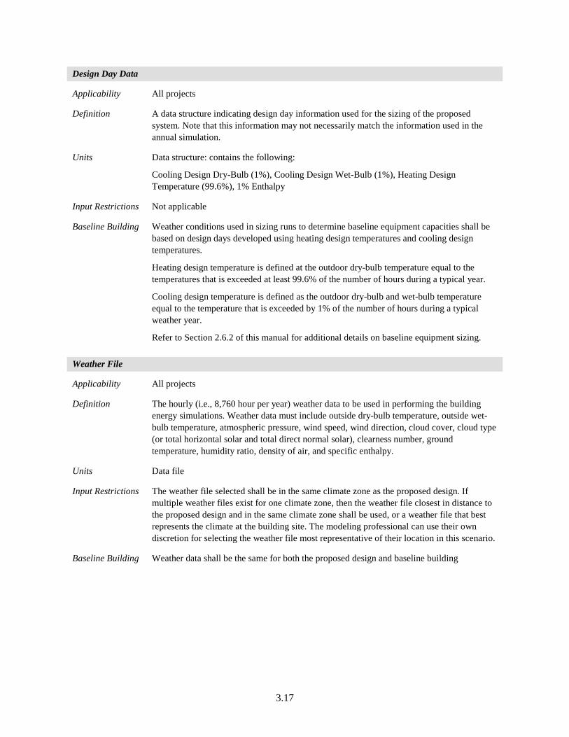
3.17
Design Day Data
Applicability All projects
Definition A data structure indicating design day information used for the sizing of the proposed system. Note that this information may not necessarily match the information used in the annual simulation.
Units Data structure: contains the following:
Cooling Design Dry-Bulb (1%), Cooling Design Wet-Bulb (1%), Heating Design Temperature (99.6%), 1% Enthalpy
Input Restrictions Not applicable
Baseline Building Weather conditions used in sizing runs to determine baseline equipment capacities shall be based on design days developed using heating design temperatures and cooling design temperatures.
Heating design temperature is defined at the outdoor dry-bulb temperature equal to the temperatures that is exceeded at least 99.6% of the number of hours during a typical year.
Cooling design temperature is defined as the outdoor dry-bulb and wet-bulb temperature equal to the temperature that is exceeded by 1% of the number of hours during a typical weather year.
Refer to Section 2.6.2 of this manual for additional details on baseline equipment sizing.
Weather File
Applicability All projects
Definition The hourly (i.e., 8,760 hour per year) weather data to be used in performing the building energy simulations. Weather data must include outside dry-bulb temperature, outside wet-bulb temperature, atmospheric pressure, wind speed, wind direction, cloud cover, cloud type (or total horizontal solar and total direct normal solar), clearness number, ground temperature, humidity ratio, density of air, and specific enthalpy.
Units Data file
Input Restrictions The weather file selected shall be in the same climate zone as the proposed design. If multiple weather files exist for one climate zone, then the weather file closest in distance to the proposed design and in the same climate zone shall be used, or a weather file that best represents the climate at the building site. The modeling professional can use their own discretion for selecting the weather file most representative of their location in this scenario.
Baseline Building Weather data shall be the same for both the proposed design and baseline building
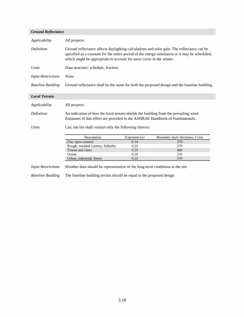
3.18
Ground Reflectance
Applicability All projects
Definition Ground reflectance affects daylighting calculations and solar gain. The reflectance can be specified as a constant for the entire period of the energy simulation or it may be scheduled, which might be appropriate to account for snow cover in the winter.
Units Data structure: schedule, fraction
Input Restrictions None
Baseline Building Ground reflectance shall be the same for both the proposed design and the baseline building.
Local Terrain
Applicability All projects
Definition An indication of how the local terrain shields the building from the prevailing wind. Estimates of this effect are provided in the ASHRAE Handbook of Fundamentals.
Units List: the list shall contain only the following choices:
Description Exponent (α) Boundary layer thickness, δ (m) Flat, open country 0.14 270 Rough, wooded country, Suburbs 0.22 370 Towns and cities 0.33 460 Ocean 0.10 210 Urban, industrial, forest 0.22 370
Input Restrictions Weather data should be representative of the long-term conditions at the site
Baseline Building The baseline building terrain should be equal to the proposed design
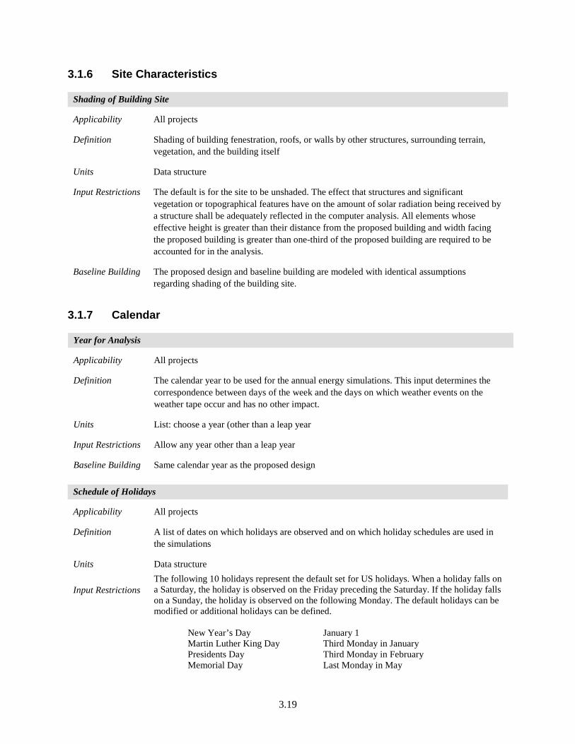
3.19
3.1.6 Site Characteristics
Shading of Building Site
Applicability All projects
Definition Shading of building fenestration, roofs, or walls by other structures, surrounding terrain, vegetation, and the building itself
Units Data structure
Input Restrictions The default is for the site to be unshaded. The effect that structures and significant vegetation or topographical features have on the amount of solar radiation being received by a structure shall be adequately reflected in the computer analysis. All elements whose effective height is greater than their distance from the proposed building and width facing the proposed building is greater than one-third of the proposed building are required to be accounted for in the analysis.
Baseline Building The proposed design and baseline building are modeled with identical assumptions regarding shading of the building site.
3.1.7 Calendar
Year for Analysis
Applicability All projects
Definition The calendar year to be used for the annual energy simulations. This input determines the correspondence between days of the week and the days on which weather events on the weather tape occur and has no other impact.
Units List: choose a year (other than a leap year
Input Restrictions Allow any year other than a leap year
Baseline Building Same calendar year as the proposed design
Schedule of Holidays
Applicability All projects
Definition A list of dates on which holidays are observed and on which holiday schedules are used in the simulations
Units Data structure
Input Restrictions The following 10 holidays represent the default set for US holidays. When a holiday falls on a Saturday, the holiday is observed on the Friday preceding the Saturday. If the holiday falls on a Sunday, the holiday is observed on the following Monday. The default holidays can be modified or additional holidays can be defined. New Year’s Day January 1 Martin Luther King Day Third Monday in January Presidents Day Third Monday in February Memorial Day Last Monday in May
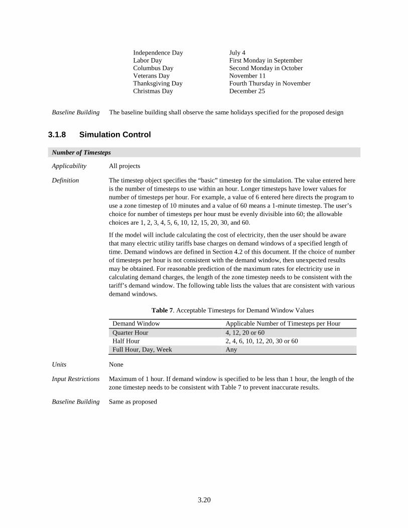
3.20
Independence Day July 4 Labor Day First Monday in September Columbus Day Second Monday in October Veterans Day November 11 Thanksgiving Day Fourth Thursday in November Christmas Day December 25
Baseline Building The baseline building shall observe the same holidays specified for the proposed design
3.1.8 Simulation Control
Number of Timesteps
Applicability All projects
Definition The timestep object specifies the “basic” timestep for the simulation. The value entered here is the number of timesteps to use within an hour. Longer timesteps have lower values for number of timesteps per hour. For example, a value of 6 entered here directs the program to use a zone timestep of 10 minutes and a value of 60 means a 1-minute timestep. The user’s choice for number of timesteps per hour must be evenly divisible into 60; the allowable choices are 1, 2, 3, 4, 5, 6, 10, 12, 15, 20, 30, and 60.
If the model will include calculating the cost of electricity, then the user should be aware that many electric utility tariffs base charges on demand windows of a specified length of time. Demand windows are defined in Section 4.2 of this document. If the choice of number of timesteps per hour is not consistent with the demand window, then unexpected results may be obtained. For reasonable prediction of the maximum rates for electricity use in calculating demand charges, the length of the zone timestep needs to be consistent with the tariff’s demand window. The following table lists the values that are consistent with various demand windows.
Table 7. Acceptable Timesteps for Demand Window Values
Demand Window Applicable Number of Timesteps per Hour Quarter Hour 4, 12, 20 or 60 Half Hour 2, 4, 6, 10, 12, 20, 30 or 60 Full Hour, Day, Week Any
Units None
Input Restrictions Maximum of 1 hour. If demand window is specified to be less than 1 hour, the length of the zone timestep needs to be consistent with Table 7 to prevent inaccurate results.
Baseline Building Same as proposed
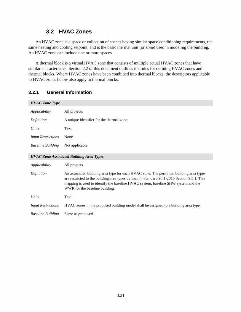
3.21
3.2 HVAC Zones
An HVAC zone is a space or collection of spaces having similar space-conditioning requirements, the same heating and cooling setpoint, and is the basic thermal unit (or zone) used in modeling the building. An HVAC zone can include one or more spaces.
A thermal block is a virtual HVAC zone that consists of multiple actual HVAC zones that have similar characteristics. Section 2.2 of this document outlines the rules for defining HVAC zones and thermal blocks. Where HVAC zones have been combined into thermal blocks, the descriptors applicable to HVAC zones below also apply to thermal blocks.
3.2.1 General Information
HVAC Zone Type
Applicability All projects
Definition A unique identifier for the thermal zone.
Units Text
Input Restrictions None
Baseline Building Not applicable
HVAC Zone Associated Building Area Types
Applicability All projects
Definition An associated building area type for each HVAC zone. The permitted building area types are restricted to the building area types defined in Standard 90.1-2016 Section 9.5.1. This mapping is used to identify the baseline HVAC system, baseline SHW system and the WWR for the baseline building.
Units Text
Input Restrictions HVAC zones in the proposed building model shall be assigned to a building area type.
Baseline Building Same as proposed
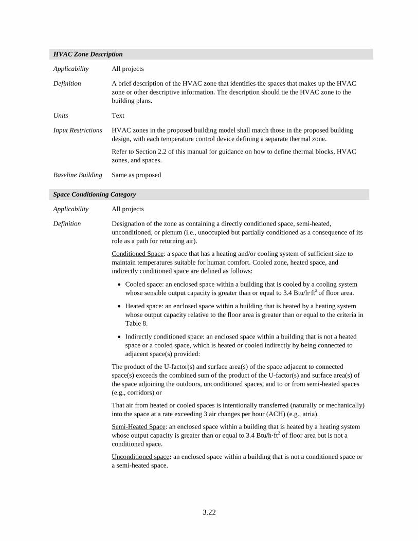
3.22
HVAC Zone Description
Applicability All projects
Definition A brief description of the HVAC zone that identifies the spaces that makes up the HVAC zone or other descriptive information. The description should tie the HVAC zone to the building plans.
Units Text
Input Restrictions HVAC zones in the proposed building model shall match those in the proposed building design, with each temperature control device defining a separate thermal zone.
Refer to Section 2.2 of this manual for guidance on how to define thermal blocks, HVAC zones, and spaces.
Baseline Building Same as proposed
Space Conditioning Category
Applicability All projects
Definition Designation of the zone as containing a directly conditioned space, semi-heated, unconditioned, or plenum (i.e., unoccupied but partially conditioned as a consequence of its role as a path for returning air).
Conditioned Space: a space that has a heating and/or cooling system of sufficient size to maintain temperatures suitable for human comfort. Cooled zone, heated space, and indirectly conditioned space are defined as follows:
• Cooled space: an enclosed space within a building that is cooled by a cooling system whose sensible output capacity is greater than or equal to 3.4 Btu/h·ft2 of floor area.
• Heated space: an enclosed space within a building that is heated by a heating system whose output capacity relative to the floor area is greater than or equal to the criteria in Table 8.
• Indirectly conditioned space: an enclosed space within a building that is not a heated space or a cooled space, which is heated or cooled indirectly by being connected to adjacent space(s) provided:
The product of the U-factor(s) and surface area(s) of the space adjacent to connected space(s) exceeds the combined sum of the product of the U-factor(s) and surface area(s) of the space adjoining the outdoors, unconditioned spaces, and to or from semi-heated spaces (e.g., corridors) or
That air from heated or cooled spaces is intentionally transferred (naturally or mechanically) into the space at a rate exceeding 3 air changes per hour (ACH) (e.g., atria).
Semi-Heated Space: an enclosed space within a building that is heated by a heating system whose output capacity is greater than or equal to 3.4 Btu/h·ft2 of floor area but is not a conditioned space.
Unconditioned space: an enclosed space within a building that is not a conditioned space or a semi-heated space.
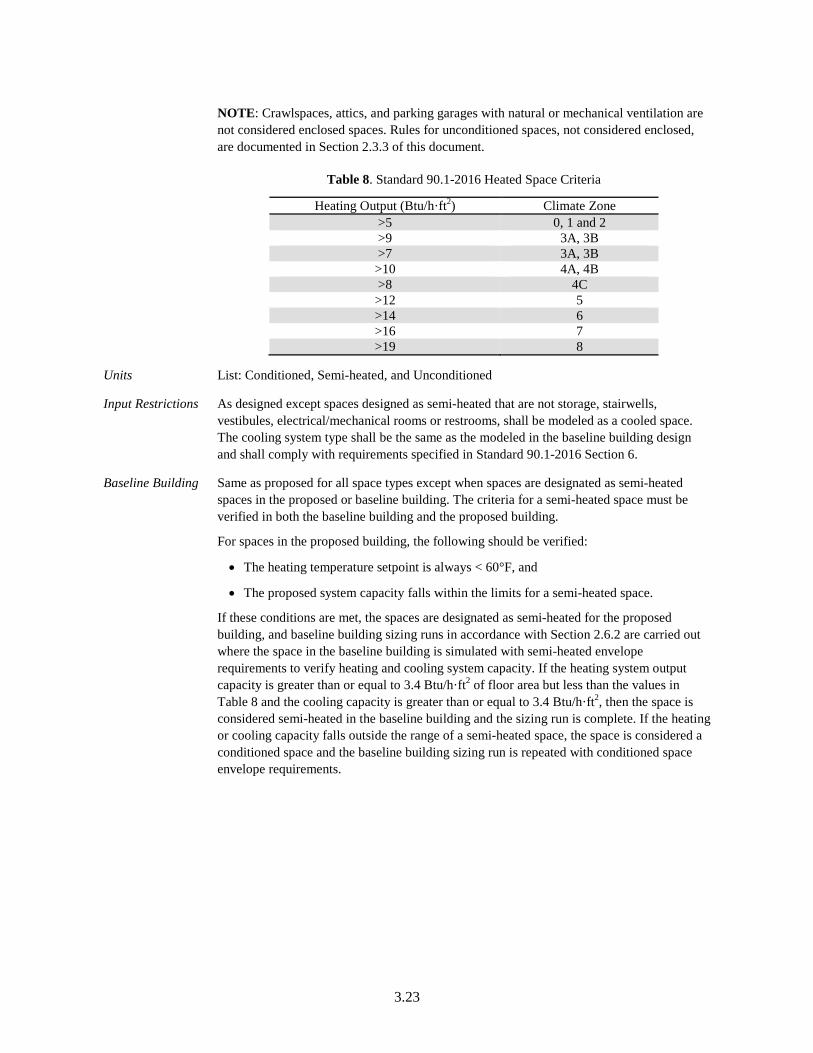
3.23
NOTE: Crawlspaces, attics, and parking garages with natural or mechanical ventilation are not considered enclosed spaces. Rules for unconditioned spaces, not considered enclosed, are documented in Section 2.3.3 of this document.
Table 8. Standard 90.1-2016 Heated Space Criteria
Heating Output (Btu/h·ft2) Climate Zone >5 0, 1 and 2 >9 3A, 3B >7 3A, 3B >10 4A, 4B >8 4C >12 5 >14 6 >16 7 >19 8
Units List: Conditioned, Semi-heated, and Unconditioned
Input Restrictions As designed except spaces designed as semi-heated that are not storage, stairwells, vestibules, electrical/mechanical rooms or restrooms, shall be modeled as a cooled space. The cooling system type shall be the same as the modeled in the baseline building design and shall comply with requirements specified in Standard 90.1-2016 Section 6.
Baseline Building Same as proposed for all space types except when spaces are designated as semi-heated spaces in the proposed or baseline building. The criteria for a semi-heated space must be verified in both the baseline building and the proposed building.
For spaces in the proposed building, the following should be verified:
• The heating temperature setpoint is always < 60°F, and
• The proposed system capacity falls within the limits for a semi-heated space.
If these conditions are met, the spaces are designated as semi-heated for the proposed building, and baseline building sizing runs in accordance with Section 2.6.2 are carried out where the space in the baseline building is simulated with semi-heated envelope requirements to verify heating and cooling system capacity. If the heating system output capacity is greater than or equal to 3.4 Btu/h·ft2 of floor area but less than the values in Table 8 and the cooling capacity is greater than or equal to 3.4 Btu/h·ft2, then the space is considered semi-heated in the baseline building and the sizing run is complete. If the heating or cooling capacity falls outside the range of a semi-heated space, the space is considered a conditioned space and the baseline building sizing run is repeated with conditioned space envelope requirements.
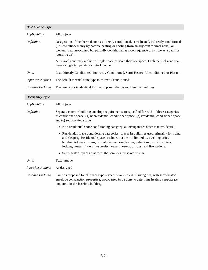
3.24
HVAC Zone Type
Applicability All projects
Definition Designation of the thermal zone as directly conditioned, semi-heated, indirectly conditioned (i.e., conditioned only by passive heating or cooling from an adjacent thermal zone), or plenum (i.e., unoccupied but partially conditioned as a consequence of its role as a path for returning air).
A thermal zone may include a single space or more than one space. Each thermal zone shall have a single temperature control device.
Units List: Directly Conditioned, Indirectly Conditioned, Semi-Heated, Unconditioned or Plenum
Input Restrictions The default thermal zone type is “directly conditioned”
Baseline Building The descriptor is identical for the proposed design and baseline building
Occupancy Type
Applicability All projects
Definition Separate exterior building envelope requirements are specified for each of three categories of conditioned space: (a) nonresidential conditioned space, (b) residential conditioned space, and (c) semi-heated space.
• Non-residential space conditioning category: all occupancies other than residential.
• Residential space conditioning categories: spaces in buildings used primarily for living and sleeping. Residential spaces include, but are not limited to, dwelling units, hotel/motel guest rooms, dormitories, nursing homes, patient rooms in hospitals, lodging houses, fraternity/sorority houses, hostels, prisons, and fire stations.
• Semi-heated: spaces that meet the semi-heated space criteria.
Units Text, unique
Input Restrictions As designed
Baseline Building Same as proposed for all space types except semi-heated. A sizing run, with semi-heated envelope construction properties, would need to be done to determine heating capacity per unit area for the baseline building.
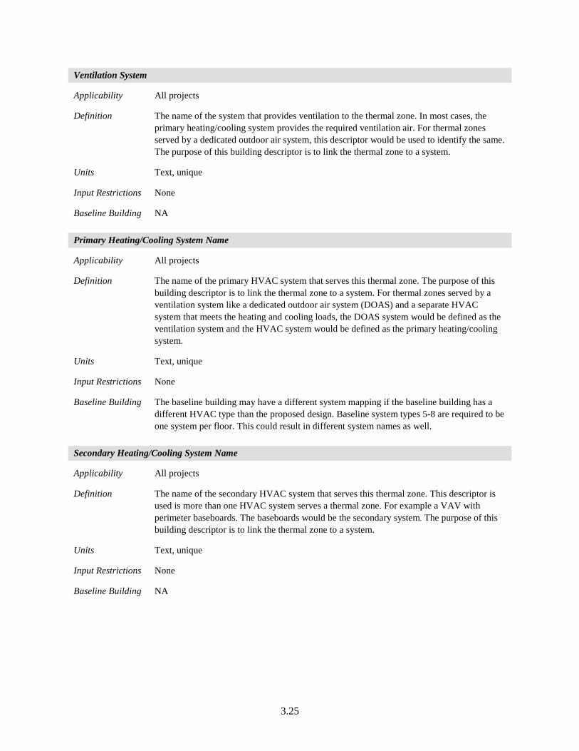
3.25
Ventilation System
Applicability All projects
Definition The name of the system that provides ventilation to the thermal zone. In most cases, the primary heating/cooling system provides the required ventilation air. For thermal zones served by a dedicated outdoor air system, this descriptor would be used to identify the same. The purpose of this building descriptor is to link the thermal zone to a system.
Units Text, unique
Input Restrictions None
Baseline Building NA
Primary Heating/Cooling System Name
Applicability All projects
Definition The name of the primary HVAC system that serves this thermal zone. The purpose of this building descriptor is to link the thermal zone to a system. For thermal zones served by a ventilation system like a dedicated outdoor air system (DOAS) and a separate HVAC system that meets the heating and cooling loads, the DOAS system would be defined as the ventilation system and the HVAC system would be defined as the primary heating/cooling system.
Units Text, unique
Input Restrictions None
Baseline Building The baseline building may have a different system mapping if the baseline building has a different HVAC type than the proposed design. Baseline system types 5-8 are required to be one system per floor. This could result in different system names as well.
Secondary Heating/Cooling System Name
Applicability All projects
Definition The name of the secondary HVAC system that serves this thermal zone. This descriptor is used is more than one HVAC system serves a thermal zone. For example a VAV with perimeter baseboards. The baseboards would be the secondary system. The purpose of this building descriptor is to link the thermal zone to a system.
Units Text, unique
Input Restrictions None
Baseline Building NA
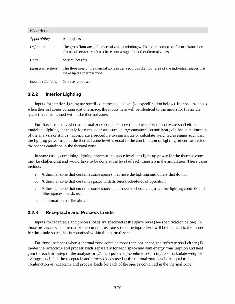
3.26
Floor Area
Applicability All projects
Definition The gross floor area of a thermal zone, including walls and minor spaces for mechanical or electrical services such as chases not assigned to other thermal zones
Units Square feet (ft²)
Input Restrictions The floor area of the thermal zone is derived from the floor area of the individual spaces that make up the thermal zone
Baseline Building Same as proposed
3.2.2 Interior Lighting
Inputs for interior lighting are specified at the space level (see specification below). In those instances when thermal zones contain just one space, the inputs here will be identical to the inputs for the single space that is contained within the thermal zone.
For those instances when a thermal zone contains more than one space, the software shall either model the lighting separately for each space and sum energy consumption and heat gain for each timestep of the analysis or it must incorporate a procedure to sum inputs or calculate weighted averages such that the lighting power used at the thermal zone level is equal to the combination of lighting power for each of the spaces contained in the thermal zone.
In some cases, combining lighting power at the space level into lighting power for the thermal zone may be challenging and would have to be done at the level of each timestep in the simulation. These cases include:
a. A thermal zone that contains some spaces that have daylighting and others that do not
b. A thermal zone that contains spaces with different schedules of operation
c. A thermal zone that contains some spaces that have a schedule adjusted for lighting controls and other spaces that do not
d. Combinations of the above
3.2.3 Receptacle and Process Loads
Inputs for receptacle and process loads are specified at the space level (see specification below). In those instances when thermal zones contain just one space, the inputs here will be identical to the inputs for the single space that is contained within the thermal zone.
For those instances when a thermal zone contains more than one space, the software shall either (1) model the receptacle and process loads separately for each space and sum energy consumption and heat gain for each timestep of the analysis or (2) incorporate a procedure to sum inputs or calculate weighted averages such that the receptacle and process loads used at the thermal zone level are equal to the combination of receptacle and process loads for each of the spaces contained in the thermal zone.
3.27
When the spaces contained in a thermal zone have different schedules, combining receptacle and process loads from the space level may be challenging and would have to be done at the level of each timestep in the simulation. See discussion above on lighting.
3.2.4 Occupants
Inputs for occupant loads are specified at the space level (see specification below). In those instances when thermal zones contain just one space, the inputs here will be identical to the inputs for the single space that is contained within the thermal zone.
For those instances when a thermal zone contains more than one space, the software shall either (1) model the occupant loads separately for each space and the heat gain for each timestep of the analysis or (2) incorporate a procedure to sum inputs or calculate weighted averages such that the occupant loads used at the thermal zone level are equal to the combination of occupant loads for each of the spaces contained in the thermal zone.
When the spaces contained in a thermal zone have different occupant schedules, rolling up occupant loads from the space level may be challenging and would have to be done at the level of each timestep in the simulation.
Additionally, for occupants, outside air ventilation is potentially impacted when the Ventilation Rate Procedure (VRP) is used accordance with ASHRAE Standard 62.1-2013 (ASHRAE 2013b) or the International Mechanical Code 2015 (IMC 2015), to determine system level ventilation rates. Demand controlled ventilation (DCV) can also affect the ventilation rates based on occupancy. Section 3.5.5.5 and Section 3.5.5.4 discuss the occupancy-based ventilation requirements for VRP and DCV controls.
3.28
3.2.5 Infiltration
Infiltration Method
Applicability All projects
Definition Energy simulation programs have a variety of methods for modeling uncontrolled air leakage or infiltration.
• Some procedures use the effective leakage area (ELA), which is generally applicable for small residential-scale buildings.
• The component leakage method requires the user to specify the average leakage through the building envelope per unit area (ft²). This could be a function of floor area or a function of area of the above-grade walls.
• Other methods require the specification of a maximum rate (like air change hours), which is modified by a schedule.
Units List: ELA, Component Leakage Method (function of floor area or function of above-grade wall area or function of all exterior surfaces), ACH
Input Restrictions For Standard 90.1-2016, a fixed infiltration rate can be specified and calculated.
• As a leakage per area of exterior envelope, including the gross area of exterior walls, roofs, and exposed floors, but excluding slabs on grade and interior partitions.
• A zone ACH input
• The default method is component leakage method; however, there are no restrictions on the use of other listed methods.
Baseline Building The infiltration method used for the baseline building shall be the same as the proposed design
3.29
Infiltration Data
Applicability All projects
Definition Information needed to characterize the infiltration rate in buildings. The required information will depend on the infiltration method selected above. Infiltration shall be modeled using the same methodology, and adjustments for weather and building operation in both the proposed design and the baseline building design. These adjustments shall be made for each simulation time step and must account for but not be limited to weather conditions and HVAC system operation, including strategies that are intended to positively pressurize the building
For the effective leakage area method, typical inputs are leakage per exterior wall area in square feet or other suitable units and information to indicate the height of the building and how shielded the site is from wind pressures. Only zones with exterior surfaces are assumed to be subject to infiltration.
Units A data structure is required to define the effective leakage area model
Input Restrictions When the infiltration rate is not determined by whole building air leakage testing in accordance with ASTM E779, the air leakage rate of the building envelope (I75Pa) at a fixed building pressure differential of 0.3 in. H2O shall be defaulted to be 0.4 cfm/ ft2 of exterior building enclosure area. If infiltration rate is determined by whole building air leakage testing in accordance with ASTM E779, the actual tested values can be used. When infiltration inputs are based on air leakage testing, test results shall be submitted with the other required documentation identified in Section 5.1.2.2 The air leakage rate of the building envelope shall be converted to appropriate units for the simulation program using one of the two methods described below.
Any reasonable inputs may be specified, consistent with the chosen infiltration modeling method. Acceptable ranges for inputs should be defined for each method supported by rating software. The peak infiltration rate of the building envelope (I75Pa) at a fixed building pressure differential of 0.3 in. H2O will be defaulted to 0.4 cfm/ft2 exterior building enclosure area, unless a different value is provided by the user and approved by the rating authority.
( )2wsDwsCttBAFIonInfiltrati odbzonescheduledesign ⋅+⋅+−⋅+⋅⋅=
Where:
Infiltration = Zone infiltration airflow (m³/s-m²)
Idesign = Design zone infiltration airflow (m³/s-m²)
Fschedule = Fractional adjustment from a prescribed schedule, based on HVAC availability schedules in COMNET Appendix C (COMNET 2017) (unit less)
tzone = Zone air temperature (°C)
todb = Outdoor dry bulb temperature (°C)
ws = Wind speed (m/s)
A = Overall coefficient (unitless)
B = Temperature coefficient (1/°C)
C = Wind speed coefficient (s/m)
3.30
D = Wind speed squared coefficient (s²/m²)
The DOE-2 Infiltration methodology coefficients would be used, where:
A = 0
B = 0
C = 0.224
D = 0
above grade walls are used, the air leakage rate of the building envelope (I75Pa), at a pressure differential of 0.3 in. H2O shall be converted to appropriate units for the simulation program using the following formula describing infiltration as a function of exterior wall area:
IEW = 0.112 × I75Pa × S/AEW
Source: (ANSI/ASHRAE/IES 2016)
When the component leakage method for floor area is used, the air leakage rate of the building envelope (I75Pa), at a pressure differential of 0.3 in. H2O shall be converted to appropriate units for the simulation program using the following formula describing infiltration as a function of floor area:
IFLR = 0.112 × I75Pa × S/AFLR
When using the measured air leakage rate of the building envelope at a pressure differential of 0.3 in. H2O for the proposed design, the air leakage rate shall be calculated as follows:
I75pa = Q/S
Where:
I75Pa = Air leakage rate of the building envelope expressed in cfm/ft2 at a fixed building pressure differential of 0.3 in. H2O, or 75 Pa
Q = Volume of air in cfm flowing through the whole building envelope when subjected to an indoor/outdoor pressure differential of 0.3 in H2O or 1.57 PSF in accordance with ASTM E779
S = Total area of the envelope air pressure boundary (expressed in ft2), including the lowest floor, any below or above-grade walls, and roof (or ceiling) (including windows and skylights), separating the interior conditioned space from the unconditioned environment
IEW = Adjusted air leakage rate (expressed in cfm/ft2) of the building envelope at a reference wind speed of 10 mph and the above ground exterior wall area
AEW = Total above-grade exterior wall area, ft2
IFLR = Adjusted air leakage rate (expressed in cfm/ft2) of the building envelope at a reference wind speed of 10 mph and relative to gross floor area
AFLR = Gross floor area. ft2
3.31
Baseline Building The air leakage rate of the building envelope (I75Pa) at a fixed building pressure differential of 0.3 in. H2O shall be defaulted to be 0.4 cfm/ ft2 of exterior building enclosure area.
Infiltration modeling approach for the baseline building shall be identical to the proposed. The following aspects are required to be the same for baseline and proposed building models:
• The same methodology as defined in the section above
• Adjustments for weather. The coefficients A, B, C, D will be same as designed. If not provided by user, they would be the same as the default values outlined above.
• Building operation in both the proposed design and the baseline design
• HVAC system operation, including strategies that are intended to positively pressurize the building
NOTE: If a value for I75Pa or Q is provided by the user for the proposed design, the infiltration value would be flagged and reported by the software tool.
Infiltration Schedule
Applicability When an infiltration method is used that requires the specification of a schedule to adjust the peak infiltration rate.
Definition With the ACH method and other methods (see above), it may be necessary to specify a schedule that modifies the infiltration rate for each hour or time step of the simulation. Such schedules are typically used to account for building pressurization due to the HVAC system.
Units Data structure: schedule, fractional
Input Restrictions The schedules for infiltration can be specified by the user or the default schedule can be used. The default infiltration schedule shall be set equal to 1 when the fan system is off, and 0.25 when the fan system is on. This is based on the assumption that when the fan system is on it brings the pressure of the interior space above the pressure of the exterior, and decreases the infiltration of outside air. When the fan system is off, interior pressure drops below exterior pressure and infiltration increases. Schedules other than the default shall be permitted to account for building ingress and egress.
Baseline Building The infiltration schedule for the baseline building shall be the same as the proposed design.
3.2.6 Natural Ventilation
Natural ventilation may be modeled for a thermal zone in the proposed design when the following conditions are met:
a. Outside air intake from natural ventilation systems shall not be less than the minimum required outdoor air ventilation rates during occupied times in the proposed building model.
b. Controls for cooling system operation and availability of natural ventilation are automatic.
c. Rating authority approves of the proposed procedure.
• In the case when the thermal zone does not have a cooling system: The thermal zone in the proposed design is modeled with no cooling when the natural ventilation system maintains
3.32
temperature. For periods when the space temperature is greater than the cooling setpoint, a cooling system like the one for the baseline building is assumed to operate to maintain temperature. The fans in this simulated system cycle with loads. The corresponding thermal zone in the baseline building is not modeled with natural ventilation. The baseline building HVAC system, as defined in Standard 90.1-2016, Section G3.1.1 (Table 3 and Table 4 of this document), provides cooling to maintain thermostat setpoint.
• In the case where the thermal zone has a cooling system: In the case where the thermal zone has an installed cooling system in the proposed design, the fans are required to operate when natural ventilation is insufficient to meet cooling or outdoor air ventilation loads. The cooling system comes on when natural ventilation is insufficient to maintain the temperature setpoint.
The corresponding thermal zone in the baseline building is not modeled with natural ventilation. In the baseline building, the fans are required to run constantly during occupied periods, and cycle with loads during unoccupied periods, same as the proposed building. The baseline building HVAC system, as defined in Standard 90.1-2016, Section G3.1.1 (Table 3 and Table 4 of this document), provides cooling to maintain thermostat setpoint.
The infiltration rate for the proposed building will be as designed. If natural ventilation is modeled as an increased infiltration rate, it will be specified through two inputs: “Infiltration through building envelope” and “Infiltration as a result of automatically controlled natural ventilation system”. Infiltration as a result of automatically controlled natural ventilation is not modeled for the baseline building.
Outputs for the proposed building with natural ventilation need to demonstrate that minimum outdoor air requirements are being met during all occupied hours. Refer to Section 5.1.3.3 of this document for requirements pertaining to buildings with natural ventilation.
3.33
Natural Ventilation Method
Applicability All thermal zones with natural ventilation
Definition The method used to model natural ventilation. The choices will depend to some extent on the capabilities of the energy simulation program. One procedure that could be used with most energy simulation programs would be to approximate the effect of natural ventilation by scheduling a high rate of infiltration when conditions are right. The schedule would typically be developed through computational fluid dynamic software or with other software that can estimate the cooling benefit of natural ventilation and relate it to climate so that the schedule can be developed.
Units List: Choices depend on the capabilities of the energy simulation program
Input Restrictions As designed. If natural ventilation is modeled as an increased infiltration rate, it shall be specified through two inputs: “Infiltration through building envelope” and “Infiltration as a result of Automatically Controlled Natural Ventilation System.”
Baseline Building The baseline building is not modeled with natural ventilation. If natural ventilation is modeled as an increased infiltration rate in the proposed design, the component “Infiltration as a result of Automatically Controlled Natural Ventilation” is not modeled for the baseline building.
NOTE: If the effect of natural ventilation is approximated by scheduling a high rate of infiltration, additional documentation needs to be provided, supporting the calculation process.
Airflow Rate
Applicability All projects with natural ventilation that use a method that requires the specification of an airflow rate
Definition The rate of airflow through the thermal zone when the natural ventilation system is operating
Units ACH or cfm
Input Restrictions The airflow rate for the proposed design shall be determined using sound engineering methods, and supporting documentation shall be provided.
If not modeled directly by the simulation program, the exceptional calculation method shall be used, with proper documentation submitted.
Baseline Building The baseline building is not modeled with natural ventilation
3.34
Natural Ventilation Schedule
Applicability All projects with natural ventilation that use a method that requires a schedule
Definition A schedule that modifies the airflow rate through the thermal zone dictates when natural ventilation is enabled
Units Data structure: schedule, fractional
Input Restrictions The schedule for the proposed design shall be determined using sound engineering methods and keyed to outdoor temperature and perhaps other conditions on the weather file used for the simulation
Baseline Building The baseline building is not modeled with natural ventilation
Minimum Indoor Temperature
Applicability All projects with natural ventilation or mixed mode ventilation with automatic controls
Definition The minimum indoor temperature below which natural ventilation is disabled
Units °F
Input Restrictions As designed
Baseline Building Not applicable
Maximum Indoor Temperature
Applicability All projects with natural ventilation or mixed mode ventilation with automatic controls
Definition The maximum indoor temperature above which natural ventilation is disabled
Units °F
Input Restrictions As designed
Baseline Building Not applicable
Minimum Outdoor Temperature
Applicability All projects with natural ventilation or mixed mode ventilation with automatic controls
Definition The minimum outdoor temperature below which natural ventilation is disabled
Units °F
Input Restrictions As designed
Baseline Building Not applicable
3.35
Maximum Outdoor Temperature
Applicability All projects with natural ventilation or mixed mode ventilation with automatic controls
Definition The maximum outdoor temperature above which natural ventilation is disabled
Units °F
Input Restrictions As designed
Baseline Building Not applicable
3.2.7 Thermal Mass
This set of building descriptors characterize the thermal mass that is not explicitly captured by the definition of exterior surfaces and interior partitions.
Thermal Response Characteristics
Applicability All projects
Definition This building descriptor only addresses the building structure’s response to changes in temperature and heat flux. Thermal mass associated with floors, interior walls, and other building envelope components is derived from the thermal properties and materials that make up these components. However, if interior partitions are not explicitly entered (see below) their effect may be captured with this input.
The thermal capacitance of the building contents are typically specified in terms of the composite weight of the building contents in lb/ft² or absolute lb. In this instance, the software assumes an average specific heat for the contents. This input can also be specified as the mass of the contents multiplied by the specific heat of the contents. The latter method would be a summation, since each item may have a different specific heat.
Units lb/ft² or lb
Input Restrictions As designed
Baseline Building The interior thermal mass in the baseline building shall be the same as the proposed design
Furniture and Contents
Applicability All projects
Definition A specification of the mass and heat capacity of furniture and other elements in the interior of the building. This includes information about the coverage and weight of furniture in the space as well as how much of the floor is covered by furniture. The latter affects how much of the solar gain that enters the space is directed to the floor with delayed heat gain and how much becomes a more instantaneous load.
Units Data structure
Input Restrictions As designed
Baseline Building The interior thermal mass and modeling assumptions in the baseline building shall be the same as the proposed design.
3.36
3.3 Space Uses
Each thermal zone discussed above may be subdivided into space uses. This section presents the building descriptors that relate to the space uses. Space uses and the defaults associated with them are listed in COMNET Appendix B (COMNET 2017). Every thermal zone shall have at least one space, as defined in this section. Daylit spaces should generally be separately defined.
3.3.1 General Information
Space Function
Applicability All projects
Definition Spaces need to be identified using the Space-by-Space method, when know. When space types are not known, the Building Area Method can be used for the space use classification. The building area types and space-by-space type classifications will be defined from Standard 90.1-2016, Section 9.5.1 and Section 9.6.1 respectively.
More than one building type category may be used in a building if it is a mixed-use facility. If space type categories are used, the user may simplify the placement of the various space types within the building model, provided that building-total areas for each space type are accurate.
The allowed building types in building area method or space-by-space method are documented in COMNET Appendix B (COMNET 2017). The building or space type provides default values for the following:
• Number of Occupants (occupant density)
• Equipment Power Density
• Lighting Power Density
• Hot Water Load
• Ventilation Rate
• Schedules
When the space classification for a space is not known, the space is required to be classified as an office space.
Units List
Input Restrictions The space-by-space method is restricted to the space types defined in Section 9 of Standard 90.1 and listed in COMNET Appendix B (COMNET 2017)
Baseline Building Same as proposed
3.37
Floor Area
Applicability All projects that use the space-by-space classification method (see above)
Definition The floor area of the space. The area of the spaces that make up a thermal zone shall sum to the floor area of the thermal zone.
Units Square feet (ft²)
Input Restrictions Area shall be measured to the outside of exterior walls and to the center line of partitions
Baseline Building Same as proposed
3.3.2 Occupants
COMNET Appendix B (COMNET 2017) provides space level information on occupancy, lighting, and plug load schedules, as well as occupant density, allowed LPD, and occupant heat gain.
Number of Occupants
Applicability All projects
Definition The number of persons in a space. The number of persons is modified by an hourly schedule (see below), which approaches but does not exceed 1.0. Therefore, the number of persons specified by the building descriptor is similar to design conditions as opposed to average occupancy.
Units The number of persons may be specified in an absolute number, ft²/person, or persons/1000 ft²
Input Restrictions The design occupancy is to be used when known. For cases where the design occupancy is not known, the number of occupants given by space function in COMNET Appendix B (COMNET 2017) can be used.
Baseline Building Same as proposed
Occupant Heat Rate
Applicability All projects
Definition The sensible and latent heat produced by each occupant in an hour. This depends on the activity level of the occupants and other factors. Heat produced by occupants must be removed by the air conditioning system as well as the outside air ventilation rate and can have a significant impact on energy consumption.
Units Btu/h, specified separately for sensible and latent gains
Input Restrictions The occupant heat rate is determined by the user and, if unknown, can use the values in COMNET Appendix B (COMNET 2017)
Baseline Building Same as proposed
3.38
Occupancy Schedule
Applicability All projects
Definition The occupancy schedule modifies the number of occupants to account for expected operational patterns in the building. The schedule adjusts the heat contribution from occupants to the space hourly to reflect time-dependent usage patterns. The occupancy schedule can also affect other factors such as outside air ventilation, depending on the control mechanisms specified.
Units Data structure: schedule, fractional
Input Restrictions The actual occupancy schedule is to be used when known. When actual schedules are not known, default values specified in COMNET Appendix C (COMNET 2017) may be used
Baseline Building Same as proposed
3.3.3 Interior Lighting
For building descriptors related to exterior lighting, see Section 3.8.3 of this document.
Lighting Classification Method
Applicability Each space in the building
Definition Indoor lighting power can be specified using the building area method, or the space-by-space method. The procedure specified in Standard 90.1-2016, Section 9.6.1 should be followed while determining applicable space types, and in Section 9.5.1 to determine applicable building types.
Units List
Input Restrictions When a lighting system exists or a lighting system has been designed, it is not applicable. Where lighting neither exists nor is submitted with design documents:
• Where space types are known, lighting power shall be determined in accordance with the Space-by-Space Method (Standard 90.1-2016, Section 9.6.1).
• Where space types are not known, lighting power shall be determined in accordance with the Building Area Method (Standard 90.1-2016, Section 9.5.1).
Baseline Building Space by Space in accordance with Standard 90.1-2016 Table G3.7, except where lighting neither exists nor is submitted with design documents, the lighting classification method shall be the same as proposed.
3.39
Regulated Interior Lighting Power
Applicability All projects
Definition Total connected lighting power for all regulated interior lighting power applications except Additional Lighting Power: Retail Display Lighting Power. This includes the loads for lamps and ballasts.
Units Watts
Input Restrictions As designed. Where a complete lighting system exists or has been submitted with the design documents, the lighting system power is determined by applying the rules of Section 9.1.3 and 9.1.4 to the existing or designed fixtures and equipment excluding the applications described in the Unregulated Lighting Power and Additional Lighting Power: Retail Display Lighting Power subsections below. The modeled lighting power in each thermal block must be based on the fixtures within each thermal block. For spaces without unregulated lighting power or additional lighting power, this input will be the same as the proposed building interior lighting power.
For areas of the building where lighting neither exists nor is fully designed:
• Where space types are known, lighting power shall be determined in accordance with the Space-by-Space Method (Standard 90.1-2016, Section 9.6.1) using the values in Table 9.6.1.
• Where space types are not known, lighting power shall be determined in accordance with the Building Area Method (Standard 90.1-2016, Section 9.6.1) using the values in Table 9.5.1.
For dwelling units not less than 75% of the permanently installed lighting fixtures shall use lamps with an efficacy of at least 55 lm/W or have a total luminaire efficacy of at least 45 lm/W.
Baseline Building Where the complete lighting system exists or have been submitted with the design documents, the modeled Lighting Power in each thermal block is the sum of the product of the LPDs for the space types from Standard 90.1-2016, Table G3.7 and the floor areas for the corresponding spaces.
For areas of the building where lighting neither exists nor is fully designed in the proposed building:
• Where space types are known, baseline lighting power shall be determined using the values in Table G3.7 as described above.
• Where space types are not known, the baseline lighting power in each thermal block is the sum of the product of the area of the block and the LPD in the Building Area Method, Table G3.8 of Standard 90.1-2016.
For dwelling units the regulated interior lighting power is same as proposed. For spaces without unregulated lighting power or additional lighting power, this input will be the same as the baseline building interior lighting power.
3.40
Additional Lighting Power: Retail Display Lighting Power
Applicability All projects that have display lighting in retail spaces when using the space-by-space classification
Definition Display lighting is special lighting to highlight merchandise. To qualify for display lighting under these standards, the lighting must be specifically designed and directed to highlight merchandise and separately controlled from the general lighting. ASHRAE Standard 90.1-2016 defines the following types of retail lighting:
Retail Area Type 1: Includes all retail sales floor area that doesn’t qualify for Type 2, 3, or 4. The additional allowance for this type is 0.45 W/ft2.
Retail Area Type 2: Includes the sales floor area for vehicles, sporting goods, and small electronics. The allowance is 0.45 W/ft2.
Retail Area Type 3: Includes sales floor area for the sale of furniture, clothing, cosmetics, and artwork. The allowance is 1.05 W/ft2.
Retail Area Type 4: Includes sales floor area for jewelry, crystal, and china. The allowance is 1.88 W/ft2.
Units W/ft2
Input Restrictions As designed. The default for lighting power for retail display wattage is 0.0 watts. The user is required to specify the purpose for additional interior lighting power allowance through retail display lighting. These are then required to be classified in one of the four categories mentioned above.
Baseline Building The floor area in Retail Area Types 1 through 3 illuminated by retail display lighting times 1.6 W/ ft2 plus the floor area in Retail Area Type 4 illuminated by retail display lighting times 3.9 W/ ft2
Unregulated Interior Lighting Power
Applicability All projects
Definition This includes power for lighting equipment and applications exempt from LPD requirements. However, these exceptions apply only to lighting systems that are an addition to general lighting and are controlled by an independent control device.
Standard 90.1-2016, Section 9.2.2.3, exempts the following lighting systems from all requirements:
a. Display or accent lighting that is an essential element for the function performed in galleries, museums, and monuments.
b. Lighting that is integral to equipment or instrumentation and is installed by its manufacturer.
c. Lighting specifically designed for use only during medical or dental procedures and lighting integral to medical equipment.
d. Lighting integral to both open and glass-enclosed refrigerator and freezer cases.
e. Lighting integral to food warming and food preparation equipment.
f. Lighting specifically designed for the life support of nonhuman life forms.
3.41
g. Lighting in retail display windows, provided the display area is enclosed by ceiling-height partitions.
h. Lighting in interior spaces that have been specifically designated as a registered interior historic landmark.
i. Lighting that is an integral part of advertising or directional signage.
j. Exit signs.
k. Lighting that is for sale or lighting educational demonstration systems.
l. Lighting for theatrical purposes, including performance, stage, and film and video production.
m. Lighting for television broadcasting in sporting activity areas.
n. Casino gaming areas.
o. Furniture-mounted supplemental task lighting that is controlled by automatic shutoff and complies with Standard 90.1-2016 Section 9.4.1.3(c).
p. Mirror lighting in dressing rooms and accent lighting in religious pulpit and choir areas.
q. Parking garage transition lighting—lighting for covered vehicle entrances and exits from buildings and parking structures—that complies with Standard 90.1-2016 Section 9.4.1.2(a) and 9.4.1.2(c); each transition zone shall not exceed a depth of 66 ft inside the structure and a width of 50 ft.
Units W/ft² or watts
Input Restrictions As designed. The unregulated lighting power should be cross-referenced to the type of exception and to the construction documents. The default for unregulated lighting power is zero.
Baseline Building The unregulated interior lighting in the baseline building shall be the same as the proposed design.
Interior Lighting Power
Applicability All spaces or projects
Definition Interior lighting power is the power used by all installed electric lighting in each space.
Units Watts
Input Restrictions Derived – not a user input. The proposed value includes all lighting and is the sum of the proposed Regulated Interior Lighting Power, Additional Lighting Power: Retail Display Lighting Power and Unregulated Interior Lighting Power
Baseline Building The baseline value is the sum of the baseline Regulated Interior Lighting Power, the Additional Lighting Power: Retail Display Lighting Power and the Unregulated Interior Lighting Power.
3.42
Automatic Interior Lighting Controls (including indoor parking garages)
Applicability All projects
Definition Automatic interior lighting controls include automatic daylight responsive controls for sidelighting and toplighting, occupancy sensors, and programmable controls such as scheduled shutoff controls. Lighting controls included in Section 9.4.1.1 of Standard 90.1-2016 are mandatory and must be included in the proposed building design. Modeling of daylighting controls is discussed in Section 3.3.4. Modeling of occupancy sensors and other automatic controls is accomplished as described below.
Units List: Control types :
a. Occupancy Sensor with full automatic on
All of the lighting is automatically controlled to turn on when occupants are detected and turn off within 20 minutes when no occupants are detected in the space
b. Occupancy Sensor restricted to partial automatic on
Between 50% and less than 100% of lighting is automatically controlled to turn on when occupants are detected and 100% of the lighting is turned off within 20 minutes when no occupants are detected in the space
c. Occupancy Sensor restricted to manual on
None of the lighting is automatically controlled to turn on when occupants are detected and 100% of the lighting is turned off within 20 minutes when no occupants are detected in the space
d. Automatic Daylight Responsive Controls for Sidelighting
Refer to Section 3.3.4 for additional details related to daylighting controls.
e. Automatic Daylight Responsive Controls for Toplighting
Refer to Section 3.3.4 for additional details related to daylighting controls.
f. Scheduled Shut-Off
All lighting in a space automatically shut-off when a space is scheduled to be unoccupied, using either a time of day control device or a signal from an automatic control device or security system.
Input Restrictions For each space in the proposed building indicate which control types from the list above are included and the wattage of lighting that is controlled. For spaces where lighting neither exists nor is submitted with design documents, mandatory controls as specified in Standard 90.1-2016 Section 9.4 shall be included.
Credit for lighting controls other than daylighting controls is taken by decreasing the lighting schedule in the proposed building design according to the following.
• Scheduled shut-off in buildings 5,000 ft2 or greater – no credit.
• Scheduled shut-off in buildings < 5,000 ft2 – decrease lighting schedule by 10% for all hours in spaces without occupancy sensor controls.
3.43
• Occupancy sensors with full automatic on – decrease the lighting schedule by the occupancy sensor reduction factor from Table G3.7 in each space with full automatic on occupancy sensors.
• Occupancy sensors with manual on or partial automatic on - decrease the lighting schedule by the occupancy sensor reduction factor from Table G3.7 multiplied by 1.25 in each space with manual on or partial on occupancy sensors.
• Occupancy sensors of any configuration controlling individual office work stations - decrease the lighting schedule by 30% for lighting with occupancy sensors controlling individual work stations in open office areas.
Baseline Building The lighting schedule for the baseline building shall be the same as proposed before lighting control credits described above are taken.
Lighting Schedules
Applicability All projects
Definition Schedule of operation for interior lighting power used to adjust the energy use of lighting systems hourly to reflect time-dependent patterns of lighting usage. Different schedules may be defined for different lighting circuits, depending on the capabilities of the software.
Units Data structure: schedule, fractional (not exceeding 1.0)
Input Restrictions Actual schedules are required to be used when available. For cases where design schedules are not available, an appropriate schedule from COMNET Appendix C (COMNET 2017) may be used. The schedules for the proposed building shall be modified according to Automatic Interior Lighting Controls and Daylighting Modeling Method
Baseline Building The baseline building shall use the same lighting schedules as the proposed design, previous to any adjustments made for automatic lighting controls or daylighting controls.
Fixture Type
Applicability All interior lighting fixtures
Definition The type of lighting fixture, which is used to determine the light heat gain distribution
Units List: one of three choices: Recessed with Lens, Recessed/Downlight, Not in Ceiling
Input Restrictions As designed
Baseline Building As designed
3.44
Luminaire Type
Applicability All interior lighting fixtures
Definition The type of lighting luminaire, which is used to determine the light heat gain distribution
The dominant luminaire type determines the daylight dimming characteristics, when there is more than one type of luminaire in the space.
Units List: Linear Fluorescent, Compact Fluorescent Lighting (CFL), Incandescent, Light Emitting Diode (LED), Metal Halide, Mercury Vapor, High Pressure Sodium
Input Restrictions As designed
Baseline Building As designed
Light Heat Gain Distribution
Applicability All projects
Definition The distribution of the heat generated by the lighting system that is directed to the space, the plenum, the HVAC return air, or other locations. This input is a function of the luminaire type and location. Luminaires recessed into a return air plenum contribute more of their heat to the plenum or the return air stream if the plenum is used for return air; while pendant mounted fixtures hanging in the space contribute more of their heat to the space. Common luminaire type/space configurations are listed in Table 3, Chapter 18, 2009 ASHRAE Handbook of Fundamentals, summarized in Table 9 below. Typically the data will be linked to a list of common luminaire configurations similar to Table 9 so that the user chooses a luminaire type category and heat gain is automatically distributed to the appropriate locations.
Units List (of luminaire types) or data structure consisting of a series of decimal fractions that assign heat gain to various locations
Input Restrictions Default values listed in Table 9 shall be used as a default when the luminaire categories apply. Where lighting fixtures having different heat venting characteristics are used within a single space, the wattage weighted average heat-to-return-air fraction shall be used. When lighting is entered through the LPD input, this value can be specified by the user for the proposed building.
Baseline Building Same as proposed
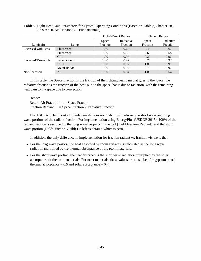
3.45
Table 9. Light Heat Gain Parameters for Typical Operating Conditions (Based on Table 3, Chapter 18, 2009 ASHRAE Handbook – Fundamentals)
Luminaire
Lamp
Ducted/Direct Return Plenum Return Space
Fraction Radiative Fraction
Space Fraction
Radiative Fraction
Recessed with Lens Fluorescent 1.00 0.67 0.45 0.67
Recessed/Downlight
Fluorescent 1.00 0.58 0.69 0.58 CFL 1.00 0.97 0.20 0.97 Incandescent 1.00 0.97 0.75 0.97 LED 1.00 0.97 1.00 0.97 Metal Halide 1.00 0.97 0.75 0.97
Not Recessed All 1.00 0.54 1.00 0.54
In this table, the Space Fraction is the fraction of the lighting heat gain that goes to the space; the radiative fraction is the fraction of the heat gain to the space that is due to radiation, with the remaining heat gain to the space due to convection.
Hence: Return Air Fraction = 1 – Space Fraction Fraction Radiant = Space Fraction × Radiative Fraction
The ASHRAE Handbook of Fundamentals does not distinguish between the short wave and long wave portions of the radiant fraction. For implementation using EnergyPlus (USDOE 2015), 100% of the radiant fraction is assigned to the long wave property in the tool (Field:Fraction Radiant), and the short wave portion (Field:Fraction Visible) is left as default, which is zero.
In addition, the only difference in implementation for fraction radiant vs. fraction visible is that:
• For the long wave portion, the heat absorbed by room surfaces is calculated as the long wave radiation multiplied by the thermal absorptance of the room materials.
• For the short wave portion, the heat absorbed is the short wave radiation multiplied by the solar absorptance of the room materials. For most materials, these values are close, i.e., for gypsum board thermal absorptance = 0.9 and solar absorptance = 0.7.
3.46
3.3.4 Daylighting Control
This group of building descriptors is applicable for spaces that have daylighting controls or daylighting control requirements. Spaces that have daylighting should be defined separately from spaces that do not.
Daylight Modeling Method
Applicability Daylighted spaces
Definition The method used to model daylighting. Building descriptors are provided in this section for an internal daylighting model, two variations of an external daylighting model, and a simplified approach based on power adjustment factors (PAFs):
Internal daylighting model. With this method, the simulation model has the capability to model the daylighting contribution for each hour of the simulation and make an adjustment to the lighting power for each hour, taking into account factors such as daylighting availability, geometry of the space, daylighting aperture, control type and the lighting system. The assumption is that the geometry of the space, the reflectance of surfaces, the size and configuration of the daylight apertures, and the light transmission of the glazing are taken from other building descriptors.
External daylighting model. An external daylighting model may be used in combination with an hourly simulation program to calculate daylighting savings as long as it produces consistent results and makes use of the key assumptions described below for internal daylighting models. Exterior daylight models include, but are not limited to, the following types of methods:
Schedule adjustments. With this method, a space is modeled in a standalone daylighting program to determine the amount of interior daylight available different times of the year and for different times of the day. In addition this program has an electric lighting model that calculates the electricity savings by hour based on interior illuminance and the daylighting control type (switching, dimming etc.). These savings values are converted into a schedule of electric lighting power reduction multipliers. This lighting power reduction schedule is applied to the proposed design energy simulation model and results in reduced electric lighting energy consumption and reduced internal heat gain, both of which are reflected in the proposed design energy consumption.
Daylight ratio. With this method, an outside program pre-calculates a relationship between outdoor daylight conditions (illuminances or luminance) and interior illuminance. Within the rating software, interior illuminance is calculated from the daylighting ratios and the daylight conditions derived from data on the local weather file. The remainder of the calculations are the same as for an internally calculated daylight model where the interior illuminances are compared to an illuminance setpoint and electric lighting power is calculated based on control type. The two most widely used methods of pre-calculating daylighting ratios are the modified daylight factor method and the daylight coefficients method.
a. The modified daylight factor method uses pre-calculated diffuse and direct illuminance daylight factors and multiplies these by diffuse and direct beam outdoor illuminance from the weather file to calculate interior illuminance (Winkelmann & Selkowitz 1985). Daylight factors are calculated from a simulation of the space that relies on user entered information about the space modeled such as orientation, geometry, material properties
3.47
(transmittances and reflectance), etc. For any given hour, the interior illuminance at the reference point is calculated by the direct beam angle specific daylight factor multiplied by the outdoor direct beam and clear sky illuminance and this is added to the overcast daylight factor multiplied by the overcast sky illuminance. Outdoor direct beam, clear sky and overcast sky illuminances are calculated from the weather data used in the proposed building energy simulation.
b. The daylight coefficients method is essentially a similar but more accurate method that relates internal illuminance to the luminance of patches of the sky (Tregenza & Waters 1983). The sky is divided up into patches as defined by altitude and azimuth. The daylight coefficients are ratios of interior illuminance to luminance for patches or areas on the sky dome. An outside daylight simulation program uses information about the space modeled: its orientation, geometry, material properties (transmittances and reflectance), etc., and calculates daylight coefficients for each sky patch. The precalculated daylight coefficients are then used to calculate interior illuminances for each hour. The illuminance for a location with the space at any point in time is the product of the luminance for each sky patch multiplied by the specific daylight coefficient for each sky patch integrated over the entire sky dome. The luminance for each sky patch is calculated from the weather data used in the proposed building energy simulation.
Units Watts
Input Restrictions As designed
Baseline Building Not applicable
3.48
Daylight Areas
Applicability All daylighted spaces
Definition The floor area that is daylighted. The skylit area is the portion of the floor area that gets daylighting from a skylight. Two types of sidelit daylighted areas are recognized. The primary daylighted area is the portion that is closest to the daylighting source and receives the most illumination. The secondary daylighted area is an area farther from the daylighting source, but still receives useful daylight.
Sidelighted Areas:
Primary Sidelighted Area: The primary daylight area for sidelighting is the area near the window with a width equal to the width of the vertical fenestration plus smaller of
a. One half of the vertical fenestration head height (where head height is the distance from the floor to the top of the glazing) or
b. The distance to any 5 ft or higher opaque vertical obstruction.
The primary sidelighted area depth is the horizontal distance perpendicular to the vertical fenestration, which is the smaller of
a. One vertical fenestration head height or
b. The distance to any 5 ft or higher opaque vertical obstruction.
Secondary Sidelighted Area: The total secondary sidelighted area is the combined secondary sidelighted area within a space. Each secondary sidelighted area is directly adjacent to a primary sidelighted area The secondary sidelighted area width is the width of the vertical fenestration plus, on each side, the smaller of-
a. One half of the vertical fenestration head height o
b. the distance to any 5 ft or higher opaque vertical obstruction.
The secondary sidelighted area depth is the horizontal distance perpendicular to the vertical fenestration, which begins at the edge of the primary sidelighted area depth and ends at the smaller of-
a. One vertical fenestration head height or,
b. The distance to any 5 ft or higher opaque vertical obstruction.
If the adjacent primary sidelighted area ends at a 5 ft or higher opaque vertical obstruction, there is no secondary sidelighted area beyond such obstruction.
Toplighted Areas under Skylights:
The daylight area under skylights is the combined daylight area under each skylight within a space. The daylight area under each skylight is bounded by the opening beneath the skylight and horizontally in each direction, the smaller of
a. 70% of the ceiling height (0.7 × CH) or
b. the distance to the nearest face of any opaque vertical obstruction, where any part of the obstruction is farther away than 70% of the distance between the top of the obstruction and the ceiling (0.7 × [CH – OH], where CH = the height of the ceiling at the lowest edge of the skylight and OH = the height to the top of the obstruction)
3.49
Toplighted Areas under Roof Monitors:
The daylight area under roof monitors is the combined daylight area under each roof monitor within each space. The daylight area under each roof monitor is the product of
a. The width of the vertical fenestration above the ceiling level plus, on each side, the smallest of • 2 ft, • The distance to any 5 ft or higher vertical obstruction, or • The distance to the edge of any primary sidelighted area
And
b. the smaller of the following horizontal distances inward from the bottom edge of the vertical fenestration: • The monitor sill height (MSH) (the vertical distance from the floor to the
bottom edge of the monitor glazing). • The distance to the nearest face of any opaque vertical obstruction, where any
part of the obstruction is farther away than the difference between the height of the obstruction and the monitor sill height (MSH – OH).
Units ft²
Input Restrictions The daylit areas in a space are derived using other modeling inputs like dimensions of the fenestration and ceiling height of the space.
Baseline Building Not applicable
3.50
Daylight Control Requirements
Applicability All spaces with daylighting controls
Definition The conditions that determine if daylighting has to be modeled in a space.
Standard 90.1-2016 identifies several types of daylighted areas: primary sidelighted area, toplighted areas under roof monitors, toplighted areas under skylights, and secondary sidelighted areas.
Primary Sidelighted Area Control Requirements:
The daylighting control system is required to have the following characteristics:
a. The calibration adjustment control shall be located no higher than 11 ft above the finished floor.
b. The photocontrol shall reduce electric lighting in response to available daylight using continuous dimming or with at least one control point between 50% and 70% of design lighting power, a second control point between 20% and 40% of design lighting power or the lowest dimming level the technology allows, and a third control point that turns off all the controlled lighting.
c. The calibration shall not require the physical presence of a person at the sensor while the calibration is processing.
Toplighted Area Control Requirements:
The toplighting daylighting control system is required to have the following characteristics
a. The photocontrol shall reduce electric lighting in response to available daylight using continuous dimming or with at least one control point that is between 50% and 70% of design lighting power, a second control point between 20% and 40% of design lighting power or the lowest dimming level the technology allows, and a third control point that turns off all the controlled lighting.
b. The calibration shall not require the physical presence of a person at the sensor while the calibration is processing.
c. General lighting in overlapping toplighted and sidelighted daylight areas shall be controlled together with general lighting in the daylight area under skylights or daylight area under roof monitors.
Units List:
• Primary Sidelighting Controls
• Secondary Sidelighting Controls
• Toplighting controls
Input Restrictions As designed
Input restrictions for sidelighted area:
In accordance to Standard 90.1-2016, daylighting controls are required for the primary sidelighted area when the input power of all general lighting completely or partially within the primary sidelighted area is 150W or greater.
3.51
In any space where the general lighting completely or partially within the primary sidelighting area and secondary sidelighting area is 300W or greater, daylighting controls are required to be installed in both primary and secondary sidelighting area. The control system is required to have characteristics as defined in the ‘Definitions’ section above.
Exceptions to Primary Sidelighted Area Requirements:
a. Primary sidelighted areas where the tops of the existing adjacent structures are twice as high above the windows as their distance from the windows
b. Sidelighted areas where the total glazing area is less than 20 ft2
c. Retail spaces.
In accordance to Standard 90.1-2016, Section 9.4.1.1(f), automatic controls are required for toplit areas when the combined input power for all general lighting completely or partially within daylight area under skylights and daylight area under roof monitors is 150 W or greater, The control system is required to have characteristics as defined in the ‘Definitions’ section above.
Exceptions to Toplight Area Control Requirements:
a. Daylighted areas under skylights where it is documented that existing adjacent structures or natural objects block direct beam sunlight for more than 1500 daytime hours per year between 8 a.m. and 4 p.m.
b. Daylighted areas where the skylight EA is less than 0.006 (0.6%).
𝑆𝑆𝑆𝑆𝑃𝑃𝐵𝐵𝐵𝐵𝐵𝐵ℎ𝑃𝑃 𝐸𝐸𝐸𝐸𝐸𝐸𝑃𝑃𝐸𝐸𝑃𝑃𝐵𝐵𝐸𝐸𝑃𝑃 𝐴𝐴𝑃𝑃𝑃𝑃𝑃𝑃𝑃𝑃𝐵𝐵𝑃𝑃𝑃𝑃 = 0.85 × 𝑆𝑆𝑆𝑆𝑃𝑃𝐵𝐵𝐵𝐵𝐵𝐵ℎ𝑃𝑃 𝐴𝐴𝑃𝑃𝑃𝑃𝑅𝑅 × 𝑆𝑆𝑆𝑆𝑃𝑃𝐵𝐵𝐵𝐵𝐵𝐵ℎ𝑃𝑃 𝑉𝑉𝑉𝑉 × 𝑊𝑊𝐵𝐵
𝐷𝐷𝑅𝑅𝑃𝑃𝐵𝐵𝐵𝐵𝑃𝑃 𝐴𝐴𝑃𝑃𝑃𝑃𝑅𝑅 𝐵𝐵𝐵𝐵𝐵𝐵𝑃𝑃𝑃𝑃 𝑆𝑆𝑆𝑆𝑃𝑃𝐵𝐵𝐵𝐵𝐵𝐵ℎ𝑃𝑃
Where:
Skylight Area = Total fenestration area of skylights
Skylight VT = Area weighted average visible transmittance of skylights as determined in accordance with Standard 90.1-2016, Section 5.8.2.5
WF = Area weighted average well factor, where well factor is 0.9 if light well depth is less than 2 ft, or 0.7 if light well depth is 2 ft or greater. Light well depth is measured vertically from the underside of the lowest point on the skylight glazing to the ceiling plane under the skylight.
c. Buildings in climate zone 8 where the input power of the general lighting within daylight areas is less than 200W.
Baseline Building Daylighting controls are not modeled for the baseline building.
3.52
Installed General Lighting Power in the Primary and Toplight Daylit Zone
Applicability Daylighted spaces
Definition The installed lighting power of general lighting in the primary and toplight daylit zone. The primary and toplight daylit zone shall be defined on the plans and be consistent with the definition of the primary and toplight daylit zone in the Standard. Note that a separate building descriptor, Fraction of Controlled Lighting, defines the fraction of the lighting power in the space that is controlled by daylighting.
Units Watts
Input Restrictions As designed
Baseline Building Not applicable
Installed General Lighting Power in the Secondary Daylit Zone
Applicability Daylighted spaces
Definition The installed lighting power of general lighting in the secondary daylit zone. The secondary daylit zone shall be defined on the plans and be consistent with the definition of the secondary daylit zone in the Standard. Note that a separate building descriptor, Fraction of Controlled Lighting, defines the fraction of the lighting power in the space that is controlled by daylighting.
Units Watts
Input Restrictions As designed
Baseline Building Not applicable
Reference Position for Illuminance Calculations
Applicability All spaces or thermal zones, depending on which object is the primary container for daylighting controls
Definition The position of the two daylight reference points within the daylit space. Lighting is maintained at or above the illuminance setpoint. Thus, for step switching controls, the combined daylight illuminance plus uncontrolled electric light illuminance at the reference position must be greater than the setpoint illuminance before the controlled lighting can be dimmed or tuned off for stepped controls. Similarly, dimming controls will be dimmed so that the combination of the daylight illuminance plus the controlled lighting illuminance is equal to the setpoint illuminance.
Units Data structure
Input Restrictions As designed
Baseline Building Not applicable
3.53
Daylight Illuminance Setpoint
Applicability Spaces with daylighting controls
Definition The design illuminance for the daylit space for purposes of daylighting control
Units Footcandles
Input Restrictions As designed, but should be consistent with the visual tasks in the space and the recommendations of Illuminating Engineering Society of North America (IES) or other lighting design guidance.
Baseline Building Not applicable. NOTE: If the user input for illumination setpoint is above or below the IESNA specification, the input should be flagged and reported in the compliance reports. The user needs to provide documentation in support of the illumination setpoint specified for the proposed design.
Fraction of Zone Controlled Lighting Power
Applicability Spaces with daylighting controls
Definition The fraction of the zone’s electric lighting power that is controlled by the daylight illuminance through all the first and second reference points
Units Numeric: fraction
Input Restrictions If there is only one reference point, then a fraction equal to:
1.0 – (Fraction of Zone Controlled by First Reference Point) is assumed to have no lighting control.
If there are 2 reference points:
1.0 – ([Fraction of Zone Controlled by First Reference Point] + [Fraction of Zone Controlled by Second Reference Point]) is assumed to have no lighting control.
Baseline Building Not applicable
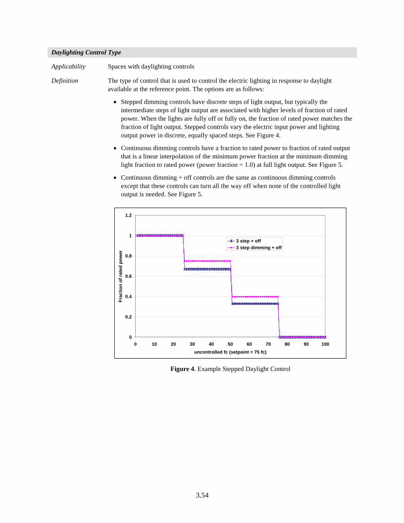
3.54
Daylighting Control Type
Applicability Spaces with daylighting controls
Definition The type of control that is used to control the electric lighting in response to daylight available at the reference point. The options are as follows:
• Stepped dimming controls have discrete steps of light output, but typically the intermediate steps of light output are associated with higher levels of fraction of rated power. When the lights are fully off or fully on, the fraction of rated power matches the fraction of light output. Stepped controls vary the electric input power and lighting output power in discrete, equally spaced steps. See Figure 4.
• Continuous dimming controls have a fraction to rated power to fraction of rated output that is a linear interpolation of the minimum power fraction at the minimum dimming light fraction to rated power (power fraction = 1.0) at full light output. See Figure 5.
• Continuous dimming + off controls are the same as continuous dimming controls except that these controls can turn all the way off when none of the controlled light output is needed. See Figure 5.
Figure 4. Example Stepped Daylight Control
0
0.2
0.4
0.6
0.8
1
1.2
0 10 20 30 40 50 60 70 80 90 100uncontrolled fc (setpoint = 75 fc)
Frac
tion
of ra
ted
pow
er
3 step + off3 step dimming + off
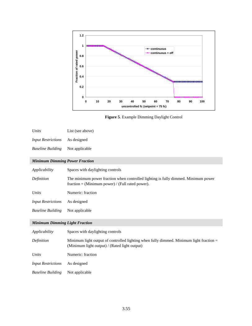
3.55
Figure 5. Example Dimming Daylight Control
Units List (see above)
Input Restrictions As designed
Baseline Building Not applicable
Minimum Dimming Power Fraction
Applicability Spaces with daylighting controls
Definition The minimum power fraction when controlled lighting is fully dimmed. Minimum power fraction = (Minimum power) / (Full rated power).
Units Numeric: fraction
Input Restrictions As designed
Baseline Building Not applicable
Minimum Dimming Light Fraction
Applicability Spaces with daylighting controls
Definition Minimum light output of controlled lighting when fully dimmed. Minimum light fraction = (Minimum light output) / (Rated light output)
Units Numeric: fraction
Input Restrictions As designed
Baseline Building Not applicable
0
0.2
0.4
0.6
0.8
1
1.2
0 10 20 30 40 50 60 70 80 90 100uncontrolled fc (setpoint = 75 fc)
Frac
tion
of ra
ted
pow
er
continuouscontinuous + off
3.56
Number of Control Steps
Applicability Daylighted spaces that use stepped controls
Definition Number of control steps. For step dimming, identifies number of steps that require fraction of rated light output and rated power fraction.
Units Numeric: integer
Input Restrictions As designed if stepped controls are provided in proposed building
Baseline Building Not applicable
3.3.5 Receptacle and Process Loads
Receptacle loads contribute to heat gains in spaces and directly use energy.
Receptacle Power
Applicability All building projects
Definition Receptacle power is power for typical general service loads in the building. Receptacle power includes equipment loads normally served through electrical receptacles, such as office equipment and printers, but does not include either task lighting or equipment used for HVAC purposes. Receptacle power values are generally higher than the largest hourly receptacle load that is actually modeled because the receptacle power values are modified by the receptacle schedule, which approaches but does not exceed 1.0.
The equipment plugged into receptacles are considered unregulated loads, hence no credit is given for improvements to the efficiency of that equipment, when the PRM is used for compliance with the standard. However, when quantifying performance that exceeds the requirements of Standard 90.1, credit for reductions in receptacle power may be granted as described below under Baseline Building.
Control of those receptacles is regulated by Standard 90.1 and that is discussed in descriptor Automatic Receptacle Control.
Units Total power (W) for the space or power density (W/ft²)
Software shall also use the prescribed values below to specify the latent heat gain fraction and the radiative/convective heat gain split.
For software that specifies the fraction of the heat gain that is lost from the space, this fraction shall be prescribed at 0 unless the equipment is located under an exhaust hood.
Input Restrictions Receptacle and process loads, such as those for office and other equipment, shall be estimated based on the building type or space type category. These loads shall be included in simulations of the building and shall be included when calculating the baseline building performance and proposed building performance.
For Standard 90.1-2016, receptacle loads in the proposed design may be calculated in one of two ways:
• As designed or assumed by the design team for loads calculation. Great care must be used in the application of space design receptacle loads from HVAC or electrical
3.57
designers as these may not include appropriate diversity to represent annual operation.
• Standard 90.1-2016 recommended defaults may be used, in which case the same values must be used for the baseline building and there is no credit for reductions.
Baseline Building The receptacle power in the baseline building shall be the same as the proposed design.
However, when quantifying performance that exceeds the requirements of Standard 90.1 (but not when using the Performance Rating as an alternative path for minimum standard compliance ), with approval of the rating authority, variations of the power requirements, schedules, or control sequences of the equipment modeled in the baseline building from those in the proposed design shall be allowed by the rating authority based upon documentation that the equipment installed in the proposed design represents a significant verifiable departure from documented conventional practice. The burden of this documentation is to demonstrate that accepted conventional practice would result in baseline building equipment different from that installed in the proposed design. If baseline building plug loads differ from the proposed building, this input must be flagged and instructions given to provide the proper documentation.
3.58
Receptacle Heat Gain Fraction
Applicability All projects
Definition The electrical input to the equipment ultimately appears as heat that contributes to zone loads. This heat can be divided into four different fractions. These are given by the input fields:
• Fraction Latent: This field is a decimal number between 0.0 and 1.0 and is used to characterize the amount of latent heat given off by electric equipment in a zone. The number specified in this field will be multiplied by the total energy consumed by electric equipment to give the amount of latent energy produced by the electric equipment. This energy affects the moisture balance within the zone.
• Fraction Radiant: This field is a decimal number between 0.0 and 1.0 and is used to characterize the amount of long-wave radiant heat being given off by electric equipment in a zone. The number specified in this field will be multiplied by the total energy consumed by electric equipment to give the amount of long wavelength radiation gain from electric equipment in a zone.
• Fraction Lost: This field is a decimal number between 0.0 and 1.0 and is used to characterize the amount of “lost” heat being given off by electric equipment in a zone. The number specified in this field will be multiplied by the total energy consumed by electric equipment to give the amount of heat that is “lost” and does not impact the zone energy balances. This might correspond to electrical energy converted to mechanical work or heat that is vented to the atmosphere.
• Fraction Convected: This field is a decimal number between 0.0 and 1.0 and is used to characterize the fraction of the heat from electric equipment convected to the zone air.
The sum of all 4 of these fractions should be 1.
Units Data structure: fraction
Input Restrictions As designed. If not specified by the user, default values for receptacle power heat gain fractions will be used.
Radiative = 0.20, Latent = 0.00, Convective = 0.80, Lost =0.00
Baseline Building Same as proposed
3.59
Receptacle Schedule
Applicability All projects
Definition Schedule for receptacle power loads used to adjust the intensity hourly to reflect time-dependent patterns of usage. These schedules are assumed to reflect the mandatory automatic receptacle control requirements.
Units Data structure: schedule, fraction
Input Restrictions Actual schedules shall be used when known. Default schedules documented in COMNET Appendix C (COMNET 2017) can be used when design schedules are not available.
Baseline Building Schedules for the baseline building shall be identical to those for the proposed design
However, when quantifying performance that exceeds the requirements of Standard 90.1 (but not when using the Performance Rating as an alternative path for minimum standard compliance ),with approval of the rating authority, variations of the power requirements, schedules, or control sequences of the equipment modeled in the baseline building from those in the proposed design shall be allowed based upon documentation that the equipment installed in the proposed design represents a significant verifiable departure from documented conventional practice. The burden of this documentation is to demonstrate that accepted conventional practice would result in baseline building equipment different from that installed in the proposed design. If baseline building plug loads differ from the proposed building, this input must be flagged and instructions given to provide the proper documentation.
Computer Room Equipment Schedule
Applicability All projects with computer rooms
Definition Schedule for computer room equipment loads used to adjust the intensity hourly to reflect time-dependent patterns of usage. Standard 90.1-2016 requires the use of a randomized schedule for computer rooms. The randomized computer room equipment schedule is intended to capture part load system performance in the proposed and base case models. While it is not realistic to have computer room loads vary drastically month to month, it is common for loads to vary gradually over months or years. The schedule shown here captures this effect in a single annual simulation. It also allows the various load conditions to be simulated under the various weather conditions.
Units Data structure: schedule, fraction
Input Restrictions Computer room equipment schedules shall be modeled as a constant fraction of the peak design load per the following monthly schedule:
Month 1, 5, 9—25%
Month 2, 6, 10—50%
Month 3, 7, 11—75%
Month 4, 8, 12—100%
Baseline Building Same as proposed
3.60
Automatic Receptacle Control
Applicability All projects
Definition Automatic receptacle controls include devices that control receptacles based on time of day, occupancy sensors or a central control signal based on occupancy as required by Standard 90.1-2016, Section 8.4.2 requires that 50% of all applicable receptacle and 25% of applicable branch circuit feeders to be controlled using automatic receptacle controls which function on either:
a. A scheduled basis using a time-of-day operated control device that turns receptacles off at specific programmed times. This shall be provided for controlled areas of no more than 5000 ft2 and not more than one floor (the occupant shall be able to manually override the control device for up to two hours);
b. An occupant sensor that shall turn receptacles off within 20 minutes of all occupants leaving a space; or
c. An automated signal from another control or alarm system that shall turn receptacles off within 20 minutes after determining that the area is unoccupied.
All controlled receptacles should be uniformly distributed throughout the space.
Plug-in controls devices cannot be used to comply with these requirements
Exceptions to this requirement include:
a. Receptacles specifically designated for equipment requiring continuous operation (24/day, 365 days/year).
b. Spaces where an automatic control would endanger the safety or security of the room or building occupants.
Units No units
Input Restrictions As designed. For each space in the proposed building indicate which receptacle control strategies from the list above are included and the percentage of receptacles that are controlled. .
Credit for receptacle controls in the proposed design is taken by decreasing the receptacle schedule in the proposed building design according to the following.
RPC = RC × 10%
Hence, the receptacle schedule for each hour for the proposed building =
EPSpro = EPSbas x (1- RPC)
Where:
RPC = Receptacle power credit
RC = Percentage of receptacles controlled according to one of the methods described above.
EPSbas = Baseline equipment power hourly schedule (fraction)
EPSpro = Proposed equipment power hourly schedule (fraction)
Baseline Building Same as proposed before the automatic receptacle control credit is applied
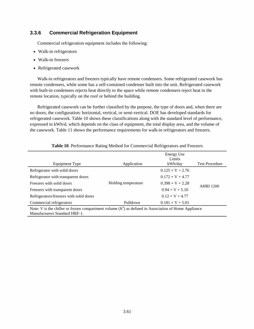
3.61
3.3.6 Commercial Refrigeration Equipment
Commercial refrigeration equipment includes the following:
• Walk-in refrigerators
• Walk-in freezers
• Refrigerated casework
Walk-in refrigerators and freezers typically have remote condensers. Some refrigerated casework has remote condensers, while some has a self-contained condenser built into the unit. Refrigerated casework with built-in condensers rejects heat directly to the space while remote condensers reject heat in the remote location, typically on the roof or behind the building.
Refrigerated casework can be further classified by the purpose, the type of doors and, when there are no doors, the configuration: horizontal, vertical, or semi-vertical. DOE has developed standards for refrigerated casework. Table 10 shows these classifications along with the standard level of performance, expressed in kWh/d, which depends on the class of equipment, the total display area, and the volume of the casework. Table 11 shows the performance requirements for walk-in refrigerators and freezers.
Table 10. Performance Rating Method for Commercial Refrigerators and Freezers
Equipment Type Application
Energy Use Limits
kWh/day Test Procedure Refrigerator with solid doors
Holding temperature
0.125 × V + 2.76
AHRI 1200
Refrigerator with transparent doors 0.172 × V + 4.77 Freezers with solid doors 0.398 × V + 2.28 Freezers with transparent doors 0.94 × V + 5.10 Refrigerators/freezers with solid doors 0.12 × V + 4.77 Commercial refrigerators Pulldown 0.181 × V + 5.01 Note: V is the chiller or frozen compartment volume (ft3) as defined in Association of Home Appliance Manufacturers Standard HRF-1.
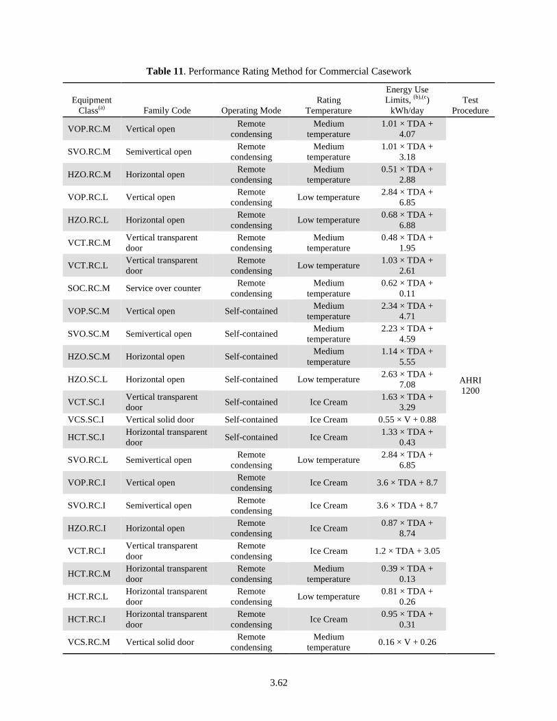
3.62
Table 11. Performance Rating Method for Commercial Casework
Equipment Class(a) Family Code Operating Mode
Rating Temperature
Energy Use Limits, (b),(c)
kWh/day Test
Procedure
VOP.RC.M Vertical open Remote condensing
Medium temperature
1.01 × TDA + 4.07
AHRI 1200
SVO.RC.M Semivertical open Remote condensing
Medium temperature
1.01 × TDA + 3.18
HZO.RC.M Horizontal open Remote condensing
Medium temperature
0.51 × TDA + 2.88
VOP.RC.L Vertical open Remote condensing Low temperature 2.84 × TDA +
6.85
HZO.RC.L Horizontal open Remote condensing Low temperature 0.68 × TDA +
6.88
VCT.RC.M Vertical transparent door
Remote condensing
Medium temperature
0.48 × TDA + 1.95
VCT.RC.L Vertical transparent door
Remote condensing Low temperature 1.03 × TDA +
2.61
SOC.RC.M Service over counter Remote condensing
Medium temperature
0.62 × TDA + 0.11
VOP.SC.M Vertical open Self-contained Medium temperature
2.34 × TDA + 4.71
SVO.SC.M Semivertical open Self-contained Medium temperature
2.23 × TDA + 4.59
HZO.SC.M Horizontal open Self-contained Medium temperature
1.14 × TDA + 5.55
HZO.SC.L Horizontal open Self-contained Low temperature 2.63 × TDA + 7.08
VCT.SC.I Vertical transparent door Self-contained Ice Cream 1.63 × TDA +
3.29 VCS.SC.I Vertical solid door Self-contained Ice Cream 0.55 × V + 0.88
HCT.SC.I Horizontal transparent door Self-contained Ice Cream 1.33 × TDA +
0.43
SVO.RC.L Semivertical open Remote condensing Low temperature 2.84 × TDA +
6.85
VOP.RC.I Vertical open Remote condensing Ice Cream 3.6 × TDA + 8.7
SVO.RC.I Semivertical open Remote condensing Ice Cream 3.6 × TDA + 8.7
HZO.RC.I Horizontal open Remote condensing Ice Cream 0.87 × TDA +
8.74
VCT.RC.I Vertical transparent door
Remote condensing Ice Cream 1.2 × TDA + 3.05
HCT.RC.M Horizontal transparent door
Remote condensing
Medium temperature
0.39 × TDA + 0.13
HCT.RC.L Horizontal transparent door
Remote condensing Low temperature 0.81 × TDA +
0.26
HCT.RC.I Horizontal transparent door
Remote condensing Ice Cream 0.95 × TDA +
0.31
VCS.RC.M Vertical solid door Remote condensing
Medium temperature 0.16 × V + 0.26
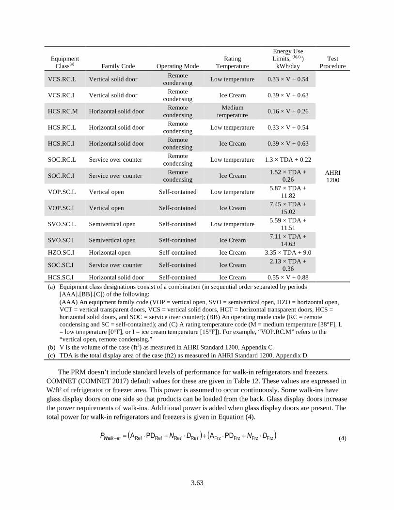
3.63
Equipment Class(a) Family Code Operating Mode
Rating Temperature
Energy Use Limits, (b),(c)
kWh/day Test
Procedure
VCS.RC.L Vertical solid door Remote condensing Low temperature 0.33 × V + 0.54
AHRI 1200
VCS.RC.I Vertical solid door Remote condensing Ice Cream 0.39 × V + 0.63
HCS.RC.M Horizontal solid door Remote condensing
Medium temperature 0.16 × V + 0.26
HCS.RC.L Horizontal solid door Remote condensing Low temperature 0.33 × V + 0.54
HCS.RC.I Horizontal solid door Remote condensing Ice Cream 0.39 × V + 0.63
SOC.RC.L Service over counter Remote condensing Low temperature 1.3 × TDA + 0.22
SOC.RC.I Service over counter Remote condensing Ice Cream 1.52 × TDA +
0.26
VOP.SC.L Vertical open Self-contained Low temperature 5.87 × TDA + 11.82
VOP.SC.I Vertical open Self-contained Ice Cream 7.45 × TDA + 15.02
SVO.SC.L Semivertical open Self-contained Low temperature 5.59 × TDA + 11.51
SVO.SC.I Semivertical open Self-contained Ice Cream 7.11 × TDA + 14.63
HZO.SC.I Horizontal open Self-contained Ice Cream 3.35 × TDA + 9.0
SOC.SC.I Service over counter Self-contained Ice Cream 2.13 × TDA + 0.36
HCS.SC.I Horizontal solid door Self-contained Ice Cream 0.55 × V + 0.88 (a) Equipment class designations consist of a combination (in sequential order separated by periods
[AAA].[BB].[C]) of the following: (AAA) An equipment family code (VOP = vertical open, SVO = semivertical open, HZO = horizontal open, VCT = vertical transparent doors, VCS = vertical solid doors, HCT = horizontal transparent doors, HCS = horizontal solid doors, and SOC = service over counter); (BB) An operating mode code (RC = remote condensing and SC = self-contained); and (C) A rating temperature code (M = medium temperature [38°F], L = low temperature [0°F], or I = ice cream temperature [15°F]). For example, “VOP.RC.M” refers to the “vertical open, remote condensing.”
(b) V is the volume of the case (ft3) as measured in AHRI Standard 1200, Appendix C. (c) TDA is the total display area of the case (ft2) as measured in AHRI Standard 1200, Appendix D.
The PRM doesn’t include standard levels of performance for walk-in refrigerators and freezers. COMNET (COMNET 2017) default values for these are given in Table 12. These values are expressed in W/ft² of refrigerator or freezer area. This power is assumed to occur continuously. Some walk-ins have glass display doors on one side so that products can be loaded from the back. Glass display doors increase the power requirements of walk-ins. Additional power is added when glass display doors are present. The total power for walk-in refrigerators and freezers is given in Equation (4).
( ) ( )FrzFrzFrzFrzReReRefRef PDAPDA DNDNP ffinWalk ⋅++⋅+= ⋅⋅− (4)
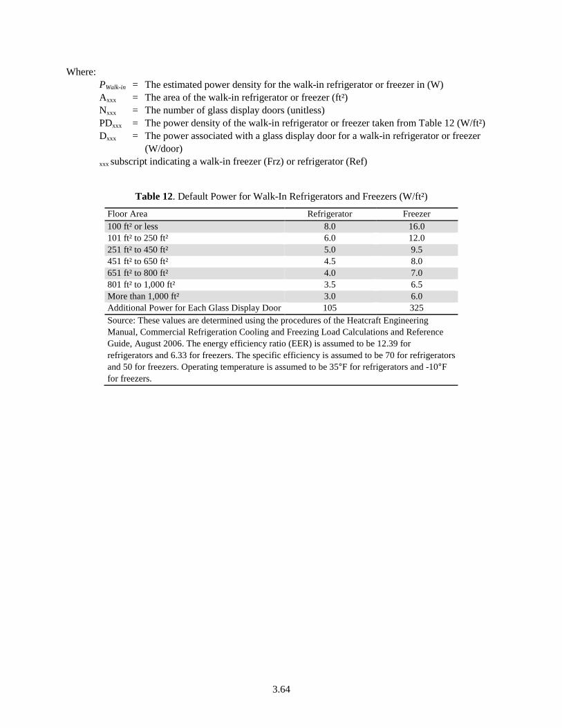
3.64
Where: PWalk-in = The estimated power density for the walk-in refrigerator or freezer in (W) Axxx = The area of the walk-in refrigerator or freezer (ft²) Nxxx = The number of glass display doors (unitless) PDxxx = The power density of the walk-in refrigerator or freezer taken from Table 12 (W/ft²) Dxxx = The power associated with a glass display door for a walk-in refrigerator or freezer
(W/door) xxx subscript indicating a walk-in freezer (Frz) or refrigerator (Ref)
Table 12. Default Power for Walk-In Refrigerators and Freezers (W/ft²)
Floor Area Refrigerator Freezer 100 ft² or less 8.0 16.0 101 ft² to 250 ft² 6.0 12.0 251 ft² to 450 ft² 5.0 9.5 451 ft² to 650 ft² 4.5 8.0 651 ft² to 800 ft² 4.0 7.0 801 ft² to 1,000 ft² 3.5 6.5 More than 1,000 ft² 3.0 6.0 Additional Power for Each Glass Display Door 105 325 Source: These values are determined using the procedures of the Heatcraft Engineering Manual, Commercial Refrigeration Cooling and Freezing Load Calculations and Reference Guide, August 2006. The energy efficiency ratio (EER) is assumed to be 12.39 for refrigerators and 6.33 for freezers. The specific efficiency is assumed to be 70 for refrigerators and 50 for freezers. Operating temperature is assumed to be 35°F for refrigerators and -10°F for freezers.
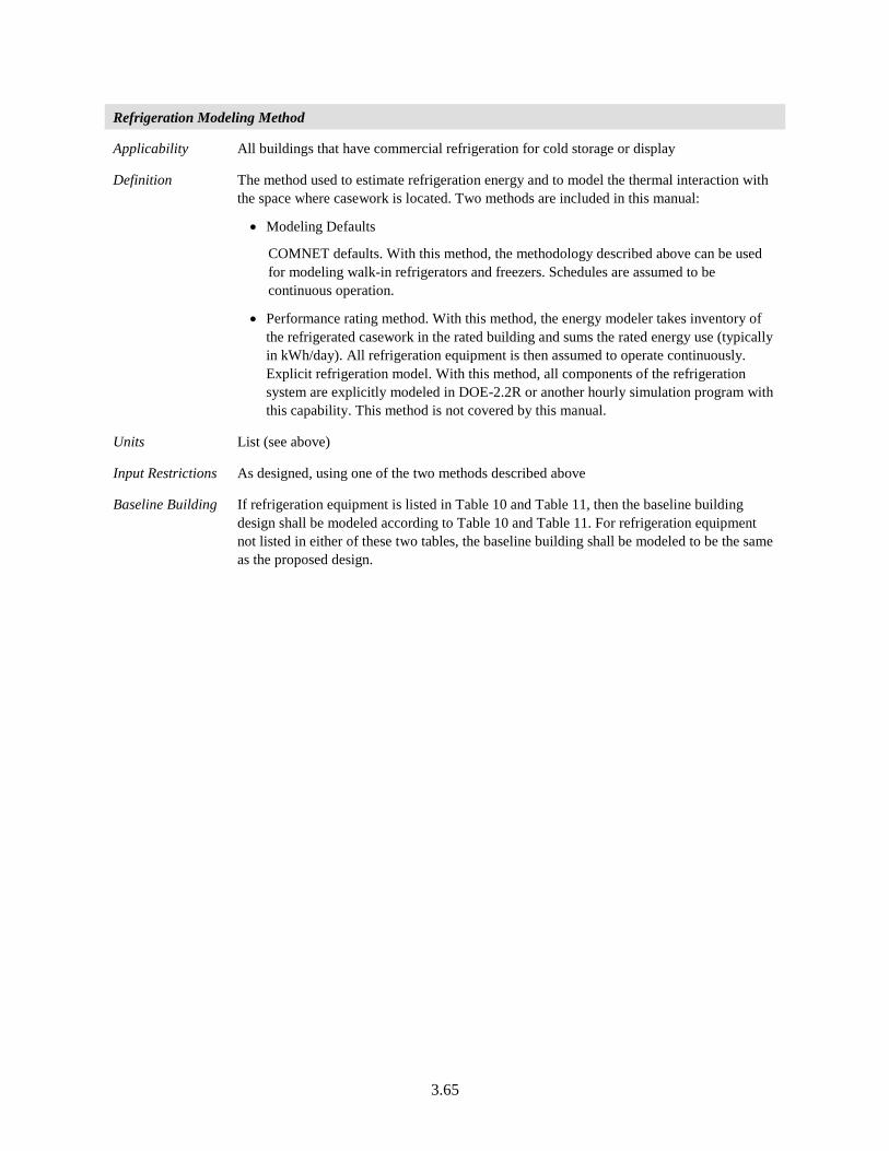
3.65
Refrigeration Modeling Method
Applicability All buildings that have commercial refrigeration for cold storage or display
Definition The method used to estimate refrigeration energy and to model the thermal interaction with the space where casework is located. Two methods are included in this manual:
• Modeling Defaults
COMNET defaults. With this method, the methodology described above can be used for modeling walk-in refrigerators and freezers. Schedules are assumed to be continuous operation.
• Performance rating method. With this method, the energy modeler takes inventory of the refrigerated casework in the rated building and sums the rated energy use (typically in kWh/day). All refrigeration equipment is then assumed to operate continuously. Explicit refrigeration model. With this method, all components of the refrigeration system are explicitly modeled in DOE-2.2R or another hourly simulation program with this capability. This method is not covered by this manual.
Units List (see above)
Input Restrictions As designed, using one of the two methods described above
Baseline Building If refrigeration equipment is listed in Table 10 and Table 11, then the baseline building design shall be modeled according to Table 10 and Table 11. For refrigeration equipment not listed in either of these two tables, the baseline building shall be modeled to be the same as the proposed design.
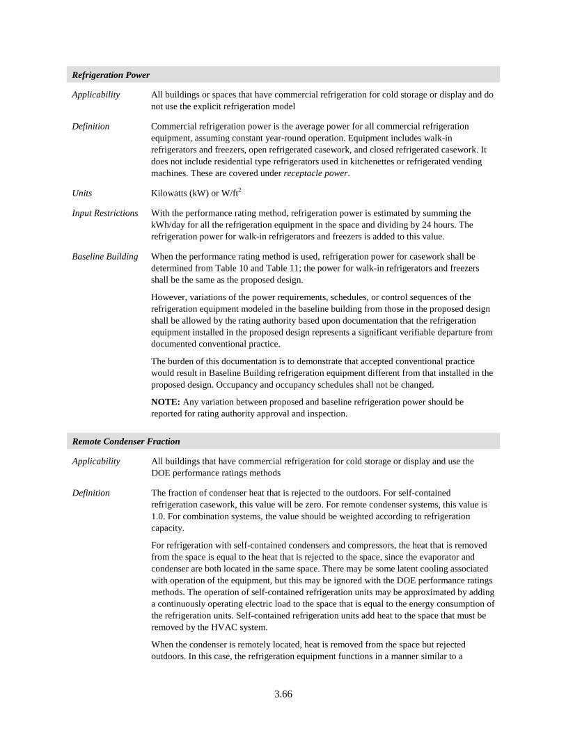
3.66
Refrigeration Power
Applicability All buildings or spaces that have commercial refrigeration for cold storage or display and do not use the explicit refrigeration model
Definition Commercial refrigeration power is the average power for all commercial refrigeration equipment, assuming constant year-round operation. Equipment includes walk-in refrigerators and freezers, open refrigerated casework, and closed refrigerated casework. It does not include residential type refrigerators used in kitchenettes or refrigerated vending machines. These are covered under receptacle power.
Units Kilowatts (kW) or W/ft2
Input Restrictions With the performance rating method, refrigeration power is estimated by summing the kWh/day for all the refrigeration equipment in the space and dividing by 24 hours. The refrigeration power for walk-in refrigerators and freezers is added to this value.
Baseline Building When the performance rating method is used, refrigeration power for casework shall be determined from Table 10 and Table 11; the power for walk-in refrigerators and freezers shall be the same as the proposed design.
However, variations of the power requirements, schedules, or control sequences of the refrigeration equipment modeled in the baseline building from those in the proposed design shall be allowed by the rating authority based upon documentation that the refrigeration equipment installed in the proposed design represents a significant verifiable departure from documented conventional practice.
The burden of this documentation is to demonstrate that accepted conventional practice would result in Baseline Building refrigeration equipment different from that installed in the proposed design. Occupancy and occupancy schedules shall not be changed.
NOTE: Any variation between proposed and baseline refrigeration power should be reported for rating authority approval and inspection.
Remote Condenser Fraction
Applicability All buildings that have commercial refrigeration for cold storage or display and use the DOE performance ratings methods
Definition The fraction of condenser heat that is rejected to the outdoors. For self-contained refrigeration casework, this value will be zero. For remote condenser systems, this value is 1.0. For combination systems, the value should be weighted according to refrigeration capacity.
For refrigeration with self-contained condensers and compressors, the heat that is removed from the space is equal to the heat that is rejected to the space, since the evaporator and condenser are both located in the same space. There may be some latent cooling associated with operation of the equipment, but this may be ignored with the DOE performance ratings methods. The operation of self-contained refrigeration units may be approximated by adding a continuously operating electric load to the space that is equal to the energy consumption of the refrigeration units. Self-contained refrigeration units add heat to the space that must be removed by the HVAC system.
When the condenser is remotely located, heat is removed from the space but rejected outdoors. In this case, the refrigeration equipment functions in a manner similar to a
3.67
continuously running split system air conditioner. Some heat is added to the space for the evaporator fan, the anti-fog heaters, and other auxiliary energy uses, but refrigeration systems with remote condensers remove more heat from the space where they are located than they add. The HVAC system must compensate for this imbalance.
For remotely located condensers using the DOE performance rating method, the heat that is removed from the space is determined as follows:
( )[ ] 413.3)(1 ×××−×−= COPkWFkWFQ (5)
Where:
Q = The rate of heat removal from the space due to the continuous operation of the refrigeration system (kBtu/h). A negative number means that heat is being removed from the space; a positive number means that heat is being added.
kW = The power of the refrigeration system determined by using the DOE performance rating method (kW)
F = The remote condenser fraction (see building descriptor below) (unitless)
COP = The coefficient of performance of the refrigeration system (unitless)
The simple approach outlined above assumes that there is no latent cooling associated with the refrigeration system. The heat addition or removal resulting from the above equation can be modeled in a number of ways to accommodate the variety of calculation engines available. It can be scheduled if the engine can accommodate a heat removal schedule. It can be modeled as a separate, constantly running air conditioner if the engine can accommodate two cooling systems serving the same thermal zone. Other modeling techniques are acceptable as long as they are thermodynamically equivalent.
Units Fraction
Input Restrictions None
Baseline Building Same as the proposed design
Refrigeration COP
Applicability All buildings that have commercial refrigeration for cold storage or display and use the DOE performance ratings methods
Definition The coefficient of performance (COP) of the refrigeration system. This is used only to determine the heat removed or added to the space, not to determine the refrigeration power or energy.
Units Fraction
Input Restrictions This value is prescribed to be 3.6 for refrigerators and 1.8 for freezers1
Baseline Building Same as the proposed design 1 These values are consistent with the assumptions for the default values for walk-ins, which assume an EER of 12.39 for refrigerators and 6.33 for freezers.
3.68
Refrigeration Schedule
Applicability All buildings that have commercial refrigeration for cold storage or display
Definition The schedule of operation for commercial refrigeration equipment. This is used to convert refrigeration power to energy use.
Units Data structure: schedule, fractional
Input Restrictions Continuous operation is prescribed
Baseline Building Same as the proposed design
3.3.7 Elevators, Escalators, and Moving Walkways
Elevators, escalators, and moving walkways account for 3% to 5% of electric energy use in buildings.2 Buildings up to about five to seven stories typically use hydraulic elevators because of their lower initial cost. Mid-rise buildings commonly use traction elevators with geared motors, while high-rise buildings typically use gearless systems where the motor directly drives the sheave. The energy using components include the motors and controls as well as the lighting and ventilation systems for the cabs.
Elevators are custom designed for each building. In this respect they are less like products than they are engineered systems, e.g., they are more akin to chilled water plants where the engineer chooses a chiller, a tower, pumping, and other components, which are field engineered into a system. The main design criteria are safety and service. Some manufacturers have focused on energy efficiency of late and introduced technologies such as advanced controls that optimize the position of cars for minimum travel and regeneration motors that become generators when a loaded car descends or an empty car rises. These technologies can result in 35% to 40% savings.2
The motors and energy using equipment is often located within the building envelope so it produces heat that must be removed by ventilation or by air conditioning systems. In energy models, a dedicated thermal zone (elevator shaft) will typically be created and this space can be indirectly cooled (from adjacent spaces) or positively cooled. Motors, drives, and braking equipment are usually located in a separate space that is often cooled by independent cooling equipment. The elevator energy use should be divided equally between the shaft and the equipment room. In the scenario, where geometrically modeling a separate elevator shaft is complicated, it is acceptable to model separate “virtual” shaft space/zones on each floor. These spaces need to be identified so that they’re not included in the gross floor area calculation.
2 Sachs, Harvey M., Opportunities for Elevator Energy Efficiency Improvements, American Council for an Energy Efficient Economy, April 2005.
3.69
Elevator/Escalator Power
Applicability All buildings that have elevators, escalators, or moving walkways
Definition The power for elevators, escalators, and moving walkways for different modes of operation. Elevators typically operate in three modes: active (when the car is moving passengers), ready (when the lighting and ventilation systems are active but the car is not moving), and standby (when the lights and ventilation systems are off). Escalators and moving walkways are either active or turned off.
Units W/unit
Input Restrictions
The power values for different modes of operation for elevators, escalators, and moving walkways can be defined by the user if that information is available for the specific equipment being installed.
Baseline Building
Escalator power shall be same as proposed. However, when quantifying performance that exceeds the requirements of Standard 90.1 (but not when using the Performance Rating as an alternative path for minimum standard compliance ), with approval of the rating authority, variations of the power requirements, schedules, or control sequences of escalators modeled in the baseline building from those in the proposed design shall be allowed by the rating authority based upon documentation that the equipment installed in the proposed design represents a significant verifiable departure from documented conventional practice.
The elevator peak motor power shall be calculated as follows:
bhp = (Weight of Car + Rated Load – Counterweight) × Speed of Car/(33,000 × hmechanical)
(6)
Pm = bhp × 746/hmotor (7)
Where:
Weight of Car = the proposed design elevator car weight, lb
Rated Load = the proposed design elevator load at which to operate, lb
Counterweight of Car = the elevator car counterweight, from Table 13, lb
Speed of Car = the speed of the proposed elevator, ft/min
hmechanical = the mechanical efficiency of the elevator from Table 13
hmotor = the motor efficiency from Table G3.9.2
Pm = peak elevator motor power, W
The percent of peak power for each mode of operation specified in Table 13 shall be the same as proposed.
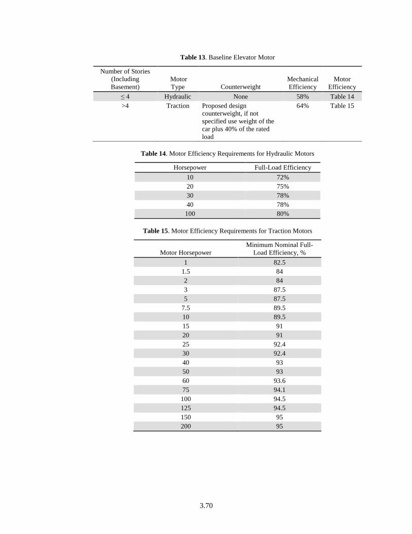
3.70
Table 13. Baseline Elevator Motor
Number of Stories (Including Basement)
Motor Type Counterweight
Mechanical Efficiency
Motor Efficiency
≤ 4 Hydraulic None 58% Table 14 >4 Traction Proposed design
counterweight, if not specified use weight of the car plus 40% of the rated load
64% Table 15
Table 14. Motor Efficiency Requirements for Hydraulic Motors
Horsepower Full-Load Efficiency 10 72% 20 75% 30 78% 40 78%
100 80%
Table 15. Motor Efficiency Requirements for Traction Motors
Motor Horsepower Minimum Nominal Full-
Load Efficiency, % 1 82.5
1.5 84 2 84 3 87.5 5 87.5
7.5 89.5 10 89.5 15 91 20 91 25 92.4 30 92.4 40 93 50 93 60 93.6 75 94.1
100 94.5 125 94.5 150 95 200 95
3.71
Elevator/Escalator Schedule
Applicability All buildings that have commercial elevators, escalators, or moving walkways
Definition The schedule of operation for elevators, escalators, and moving walkways. This is used to convert elevator/escalator power to energy use.
Units Data structure: schedule, state
Input Restrictions The schedule specified for the building should match the operation patterns of the building. If no schedules are present, defaults based NACM3 (CEC 2016) on the building area type or space type may be used.
Baseline Building Same as the proposed design
However, with approval of the rating authority variations of the schedules, or control sequences of elevators, escalators, and moving walkways modeled in the baseline building from those in the proposed design shall be allowed based upon documentation that operation of the elevators, escalators, and moving walkways installed in the proposed design represent a significant verifiable departure from documented conventional practice.
NOTE: If elevators, escalators, and moving walkways loads/schedule for the baseline building differ from the proposed design, this needs to be flagged and reported in the compliance reports.
Elevator/Escalator Ventilation Fan Power
Applicability All buildings that have commercial elevators
Definition The schedule of operations for elevator ventilation fans
Units Watts
Input Restrictions As designed
Baseline Building The baseline elevator cab ventilation shall be 0.33 W/cfm and will be modeled with the same airflow as the proposed design.
Elevator/Escalator Ventilation Fan Schedule
Applicability All buildings that have commercial elevators
Definition The schedule of operation for the ventilation fan for the elevator cab
Units Data structure: schedule, state
Input Restrictions As designed. The elevator cab ventilation is required to be de-energized while the elevator is in standby mode or off. Therefore ventilation fans shall be modeled with the same schedule as the elevator motor.
Baseline Building The baseline elevator ventilation fan shall be modeled to run continuously
3 http://www.energy.ca.gov/title24/2016standards/ACM_Supporting_Content//
3.72
Elevator/Escalator Lighting Power
Applicability All buildings that have commercial elevators
Definition The lighting power density for the elevator cab
Units Watts
Input Restrictions As designed
Baseline Building The baseline elevator cab lighting power density shall be 3.14 W/ft2 and based on the same size elevators as the proposed design.
Elevator/Escalator Lighting Schedule
Applicability All buildings that have commercial elevators
Definition The schedule of operation for the elevator cab lighting
Units Data structure: schedule, state
Input Restrictions As designed. The elevator cab lighting is required to be de-energized while the elevator is in standby mode or off. Therefore cab lighting shall be modeled with the same schedule as the elevator motor.
Baseline Building The baseline elevator cab lighting shall be modeled to run continuously
3.3.8 Gas Process Equipment
Commercial gas equipment includes the following:
• Ovens
• Fryers
• Grills
• Other equipment
The majority of gas equipment is located in the space, but is often placed under an exhaust hood, and may contribute both sensible and latent heat. Gas equipment is typically modeled by specifying the rate of peak gas consumption and modifying this with a fractional schedule. Energy consumption data for gas equipment is only beginning to emerge.
Because of these limits, the procedure for commercial gas is limited. The procedure consists of default values for power density for both the proposed design and the baseline building. These defaults can be overridden if actual values are known. No credit for commercial gas energy efficiency features is offered.
COMNET Appendix B (COMNET 2017) specifies default values that can be used for process and gas loads. Schedules are specified in COMNET Appendix C (COMNET 2017) that reflect diversity in equipment operation. Process and gas loads can also be specified through an input for peak equipment power and associated diversity schedule.
3.73
Gas Equipment Power and Power Density
Applicability All buildings that have commercial gas equipment
Definition Commercial gas power density is the peak power for commercial gas equipment, with operation schedules defined through a separate descriptor.
The gas equipment energy use can also be defined through an input of peak gas equipment power with operation schedules defined through a separate descriptor.
Units Btu/h or Btu/h-ft²
Input Restrictions As designed. For cases where design values are not available, defaults specified in COMNET Appendix B (COMNET 2017) may be used.
Baseline Building Same as the proposed design. However, when quantifying performance that exceeds the requirements of Standard 90.1 (but not when using the Performance Rating as an alternative path for minimum standard compliance ), variations of the power requirements, schedules, or control sequences of the gas equipment modeled in the baseline building from those in the proposed design shall be allowed by the rating authority based upon documentation that the gas equipment installed in the proposed design represents a significant verifiable departure from documented conventional practice.
The burden of this documentation is to demonstrate that accepted conventional practice would result in baseline building gas equipment different from that installed in the proposed design. Occupancy and occupancy schedules shall not be changed.
NOTE: Any variation between proposed and baseline gas equipment power should be flagged for rating authority approval and inspection.
Gas Equipment Heat Gain Fractions
Applicability All projects
Definition The fuel input to the gas equipment ultimately appears as heat that contributes to zone loads. This heat can be divided into four different fractions. These are given by the input fields.
• Fraction Latent: This field is a decimal number between 0.0 and 1.0 and is used to characterize the amount of latent heat given off by the gas equipment in a zone. The number specified in this field will be multiplied by the total energy consumed by gas equipment to give the amount of latent energy produced by the gas equipment. This energy affects the moisture balance within the zone.
• Fraction Radiant: This field is a decimal number between 0.0 and 1.0 and is used to characterize the amount of long-wave radiant heat being given off by gas equipment in a zone. The number specified in this field will be multiplied by the total energy consumed by gas equipment to give the amount of long wavelength radiation gain from electric equipment in a zone.
• Fraction Lost: This field is a decimal number between 0.0 and 1.0 and is used to characterize the amount of “lost” heat being given off by gas equipment in a zone. The number specified in this field will be multiplied by the total energy consumed by gas equipment to give the amount of heat that is “lost” and does not impact the zone energy balances. This might correspond to gas energy converted to mechanical work or heat
3.74
that is vented to the atmosphere.
• Fraction Convected: This field is a decimal number between 0.0 and 1.0 and is used to characterize the fraction of the heat from gas equipment convected to the zone air.
The sum of all 4 of these fractions should be 1.
Units Data structure: fraction
Input Restrictions As designed. If not specified by the user, default values for gas equipment heat gain fractions will be used.
For software that specifies the fraction of the heat gain that is lost from the space, this fraction shall be defaulted to 0.70.
The default values for fraction radiant, fraction latent, and fraction convected will be specified as 0.15, 0.05, and 0.10 respectively.
Baseline Building Same as proposed
Gas Equipment Schedule
Applicability All buildings that have commercial gas equipment
Definition The schedule of operation for commercial gas equipment. This is used to convert gas power to energy use.
Units Data structure: schedule, fractional
Input Restrictions As determined by building owner or design professional
Baseline Building Same as the proposed design
Gas Equipment Location
Applicability All buildings that have commercial gas equipment
Definition The assumed location of the gas equipment for modeling purposes. Choices are in the space or external.
Units List (see above)
Input Restrictions As designed
Baseline Building Same as the proposed design
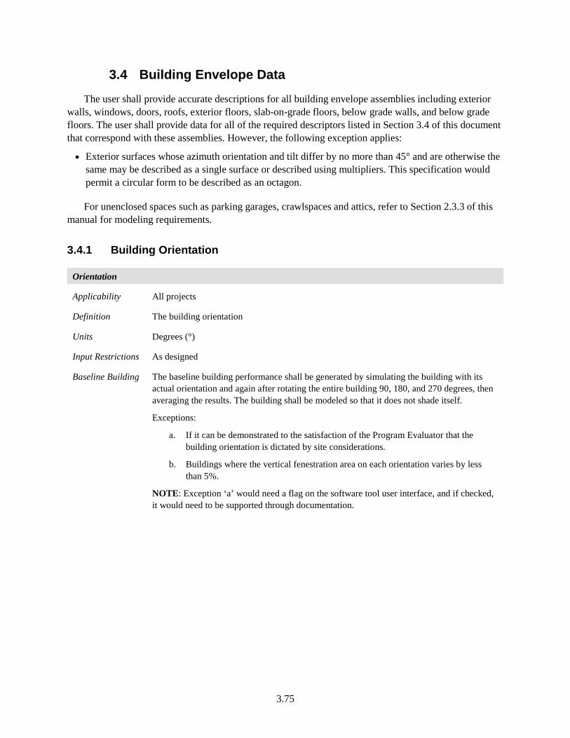
3.75
3.4 Building Envelope Data
The user shall provide accurate descriptions for all building envelope assemblies including exterior walls, windows, doors, roofs, exterior floors, slab-on-grade floors, below grade walls, and below grade floors. The user shall provide data for all of the required descriptors listed in Section 3.4 of this document that correspond with these assemblies. However, the following exception applies:
• Exterior surfaces whose azimuth orientation and tilt differ by no more than 45° and are otherwise the same may be described as a single surface or described using multipliers. This specification would permit a circular form to be described as an octagon.
For unenclosed spaces such as parking garages, crawlspaces and attics, refer to Section 2.3.3 of this manual for modeling requirements.
3.4.1 Building Orientation
Orientation
Applicability All projects
Definition The building orientation
Units Degrees (°)
Input Restrictions As designed
Baseline Building The baseline building performance shall be generated by simulating the building with its actual orientation and again after rotating the entire building 90, 180, and 270 degrees, then averaging the results. The building shall be modeled so that it does not shade itself.
Exceptions:
a. If it can be demonstrated to the satisfaction of the Program Evaluator that the building orientation is dictated by site considerations.
b. Buildings where the vertical fenestration area on each orientation varies by less than 5%.
NOTE: Exception ‘a’ would need a flag on the software tool user interface, and if checked, it would need to be supported through documentation.
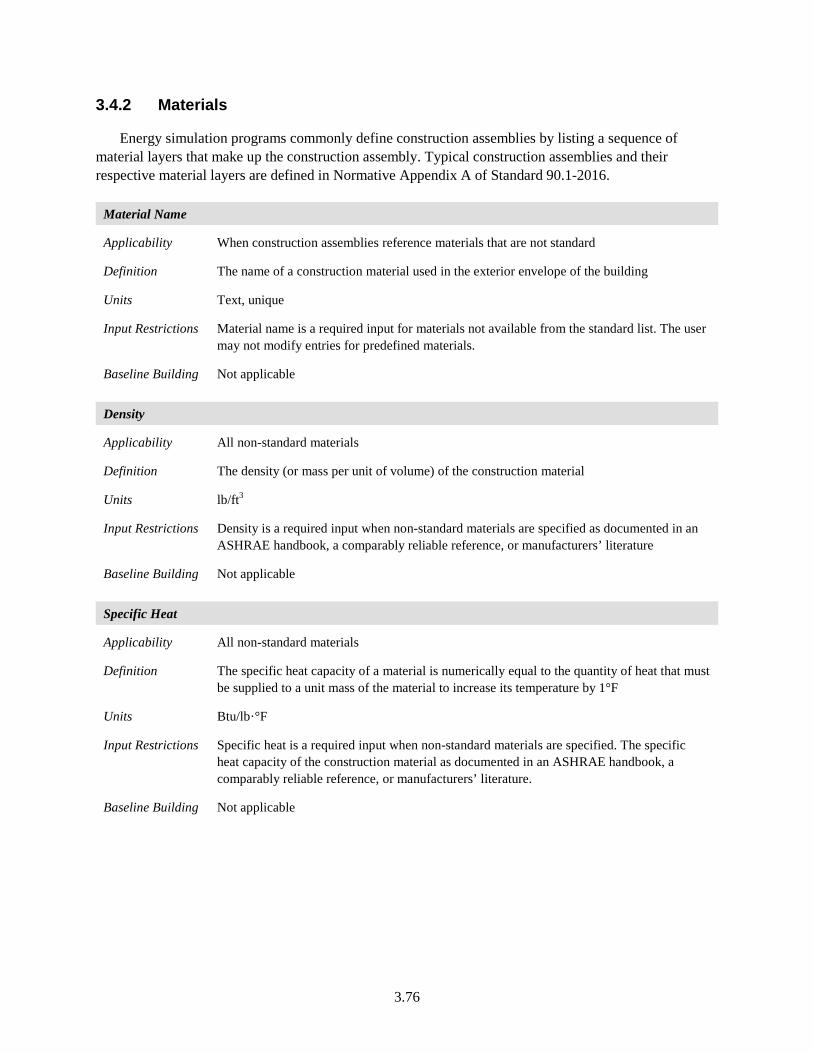
3.76
3.4.2 Materials
Energy simulation programs commonly define construction assemblies by listing a sequence of material layers that make up the construction assembly. Typical construction assemblies and their respective material layers are defined in Normative Appendix A of Standard 90.1-2016.
Material Name
Applicability When construction assemblies reference materials that are not standard
Definition The name of a construction material used in the exterior envelope of the building
Units Text, unique
Input Restrictions Material name is a required input for materials not available from the standard list. The user may not modify entries for predefined materials.
Baseline Building Not applicable
Density
Applicability All non-standard materials
Definition The density (or mass per unit of volume) of the construction material
Units lb/ft3
Input Restrictions Density is a required input when non-standard materials are specified as documented in an ASHRAE handbook, a comparably reliable reference, or manufacturers’ literature
Baseline Building Not applicable
Specific Heat
Applicability All non-standard materials
Definition The specific heat capacity of a material is numerically equal to the quantity of heat that must be supplied to a unit mass of the material to increase its temperature by 1°F
Units Btu/lb·°F
Input Restrictions Specific heat is a required input when non-standard materials are specified. The specific heat capacity of the construction material as documented in an ASHRAE handbook, a comparably reliable reference, or manufacturers’ literature.
Baseline Building Not applicable
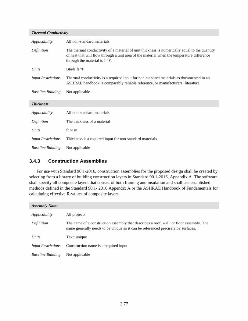
3.77
Thermal Conductivity
Applicability All non-standard materials
Definition The thermal conductivity of a material of unit thickness is numerically equal to the quantity of heat that will flow through a unit area of the material when the temperature difference through the material is 1 °F.
Units Btu/h·ft·°F
Input Restrictions Thermal conductivity is a required input for non-standard materials as documented in an ASHRAE handbook, a comparably reliable reference, or manufacturers’ literature.
Baseline Building Not applicable
Thickness
Applicability All non-standard materials
Definition The thickness of a material
Units ft or in.
Input Restrictions Thickness is a required input for non-standard materials
Baseline Building Not applicable
3.4.3 Construction Assemblies
For use with Standard 90.1-2016, construction assemblies for the proposed design shall be created by selecting from a library of building construction layers in Standard 90.1-2016, Appendix A. The software shall specify all composite layers that consist of both framing and insulation and shall use established methods defined in the Standard 90.1- 2016 Appendix A or the ASHRAE Handbook of Fundamentals for calculating effective R-values of composite layers.
Assembly Name
Applicability All projects
Definition The name of a construction assembly that describes a roof, wall, or floor assembly. The name generally needs to be unique so it can be referenced precisely by surfaces.
Units Text: unique
Input Restrictions Construction name is a required input
Baseline Building Not applicable
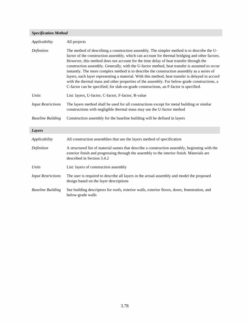
3.78
Specification Method
Applicability All projects
Definition The method of describing a construction assembly. The simpler method is to describe the U-factor of the construction assembly, which can account for thermal bridging and other factors. However, this method does not account for the time delay of heat transfer through the construction assembly. Generally, with the U-factor method, heat transfer is assumed to occur instantly. The more complex method is to describe the construction assembly as a series of layers, each layer representing a material. With this method, heat transfer is delayed in accord with the thermal mass and other properties of the assembly. For below-grade constructions, a C-factor can be specified; for slab-on-grade constructions, an F-factor is specified.
Units List: layers, U-factor, C-factor, F-factor, R-value
Input Restrictions The layers method shall be used for all constructions except for metal building or similar constructions with negligible thermal mass may use the U-factor method
Baseline Building Construction assembly for the baseline building will be defined in layers
Layers
Applicability All construction assemblies that use the layers method of specification
Definition A structured list of material names that describe a construction assembly, beginning with the exterior finish and progressing through the assembly to the interior finish. Materials are described in Section 3.4.2
Units List: layers of construction assembly
Input Restrictions The user is required to describe all layers in the actual assembly and model the proposed design based on the layer descriptions
Baseline Building See building descriptors for roofs, exterior walls, exterior floors, doors, fenestration, and below-grade walls
3.79
3.4.4 Roofs
Geometry
The geometry of roofs, walls, floors, doors, and fenestration should match the construction documents or as-built drawings as accurately as possible. Curved surfaces such as a dome or semi-circular wall may be approximated by a series of flat constructions with orientation or tilt differences of no more than 45 degrees from the actual surface.
Roof Name
Applicability All roof surfaces
Definition A unique name or code that identifies the roof and ties it to the construction documents submitted for energy code review. It is not mandatory to name roofs.
Units Text: unique
Input Restrictions None
Baseline Building None
Roof Type
Applicability All roof surfaces
Definition One of three classifications of roofs defined in Standard 90.1-2016, i.e., insulation entirely above deck, metal building, and attic and other. The prescriptive U-factor requirements for roofs depend on the type. The PRM fixes the type for the baseline building to “insulation entirely above deck.”
Units List: Attic and Other Roofs; Metal Building Roofs; and Roofs with Insulation Entirely Above Deck
Input Restrictions As designed
Baseline Building The baseline building roof type is of the type “insulation entirely above deck.” Refer to descriptor ‘Roof Construction’ for more details.
3.80
Roof Geometry
Applicability All roofs, required input
Definition Roof geometry defines the position, orientation, azimuth, tilt, and dimensions of the roof surface. The geometry of roofs should match the construction documents or as-built drawings as accurately as possible. Unusual curved surfaces such as a dome or semi-circular wall may be approximated by a series of flat constructions with orientation or tilt differences of no more than 45 degrees from the actual surface. The details of how the coordinate system is implemented may vary among software programs. The data structure for surfaces is described in Section 3.10.3 of this manual.
Units Data structure: surface
Input Restrictions The only restriction is that the surfaces defined must agree with the building being modeled, as represented on the construction drawings or as-built drawings
Baseline Building Roof geometry will be identical in the proposed and baseline building designs
Roof Construction
Applicability All roofs, required input
Definition A specification containing a series of layers that result in a construction assembly for the proposed design. The first layer in the series represents the outside (or exterior) layer and the last layer represents the inside (or interior) layer. See the building descriptors above for roof construction type.
Units List: layers
Input Restrictions The construction assembly, as designed, defined by a series of layers. Each layer specified must consist of materials as described in Section 3.4.2.
NOTE: Table A9.2A in Standard 90.1-2016 Appendix A specifies the effective insulation/framing layer R-values for roof and floor insulation installed between metal framing 4’ OC. These values are intended to be used for all other framing, 16”, 2’ and 3’.
Baseline Building Roofs in the baseline building are of the type “insulation entirely above deck.” The insulation requirement is determined by climate zone and baseline standard. The baseline building roof construction shall be modeled as layers.
For new construction, the baseline building roof type is insulation above deck. The U-factor required for baseline roof construction is defined in Table 16. The layer by layer construction corresponding to each U-factor shall be modeled as shown in Table 17. For existing buildings, the baseline roof shall follow the same rules as new buildings.
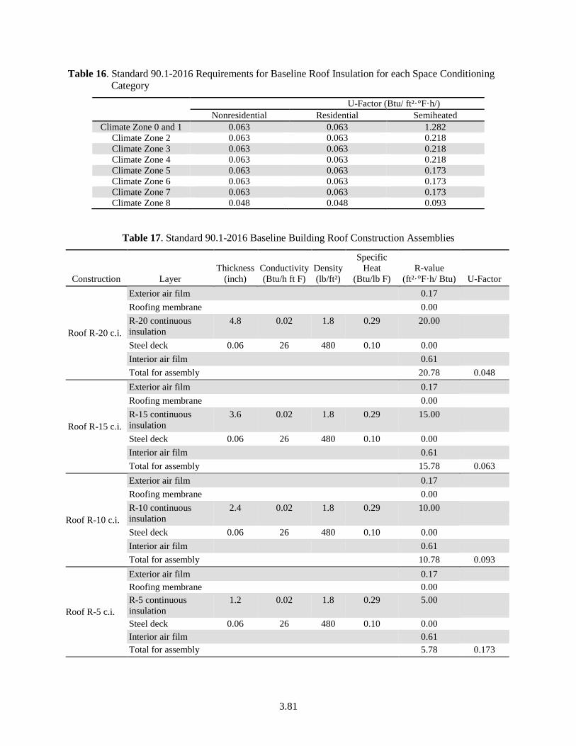
3.81
Table 16. Standard 90.1-2016 Requirements for Baseline Roof Insulation for each Space Conditioning Category
U-Factor (Btu/ ft²·°F·h/)
Nonresidential Residential Semiheated Climate Zone 0 and 1 0.063 0.063 1.282
Climate Zone 2 0.063 0.063 0.218 Climate Zone 3 0.063 0.063 0.218 Climate Zone 4 0.063 0.063 0.218 Climate Zone 5 0.063 0.063 0.173 Climate Zone 6 0.063 0.063 0.173 Climate Zone 7 0.063 0.063 0.173 Climate Zone 8 0.048 0.048 0.093
Table 17. Standard 90.1-2016 Baseline Building Roof Construction Assemblies
Construction Layer Thickness
(inch) Conductivity (Btu/h ft F)
Density (lb/ft²)
Specific Heat
(Btu/lb F) R-value
(ft²·°F·h/ Btu) U-Factor
Roof R-20 c.i.
Exterior air film 0.17 Roofing membrane 0.00 R-20 continuous insulation
4.8 0.02 1.8 0.29 20.00
Steel deck 0.06 26 480 0.10 0.00 Interior air film 0.61 Total for assembly 20.78 0.048
Roof R-15 c.i.
Exterior air film 0.17 Roofing membrane 0.00 R-15 continuous insulation
3.6 0.02 1.8 0.29 15.00
Steel deck 0.06 26 480 0.10 0.00 Interior air film 0.61 Total for assembly 15.78 0.063
Roof R-10 c.i.
Exterior air film 0.17 Roofing membrane 0.00 R-10 continuous insulation
2.4 0.02 1.8 0.29 10.00
Steel deck 0.06 26 480 0.10 0.00 Interior air film 0.61 Total for assembly 10.78 0.093
Roof R-5 c.i.
Exterior air film 0.17 Roofing membrane 0.00 R-5 continuous insulation
1.2 0.02 1.8 0.29 5.00
Steel deck 0.06 26 480 0.10 0.00 Interior air film 0.61 Total for assembly 5.78 0.173
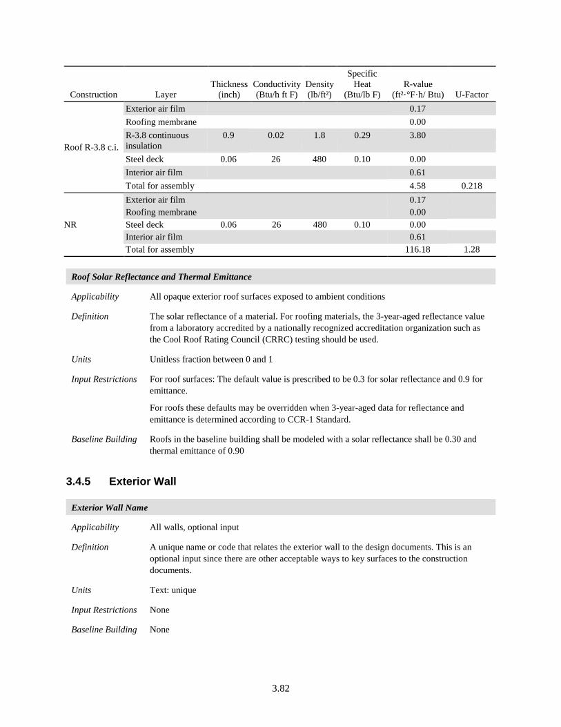
3.82
Construction Layer Thickness
(inch) Conductivity (Btu/h ft F)
Density (lb/ft²)
Specific Heat
(Btu/lb F) R-value
(ft²·°F·h/ Btu) U-Factor
Roof R-3.8 c.i.
Exterior air film 0.17 Roofing membrane 0.00 R-3.8 continuous insulation
0.9 0.02 1.8 0.29 3.80
Steel deck 0.06 26 480 0.10 0.00 Interior air film 0.61 Total for assembly 4.58 0.218
NR
Exterior air film 0.17 Roofing membrane 0.00 Steel deck 0.06 26 480 0.10 0.00 Interior air film 0.61 Total for assembly 116.18 1.28
Roof Solar Reflectance and Thermal Emittance
Applicability All opaque exterior roof surfaces exposed to ambient conditions
Definition The solar reflectance of a material. For roofing materials, the 3-year-aged reflectance value from a laboratory accredited by a nationally recognized accreditation organization such as the Cool Roof Rating Council (CRRC) testing should be used.
Units Unitless fraction between 0 and 1
Input Restrictions For roof surfaces: The default value is prescribed to be 0.3 for solar reflectance and 0.9 for emittance.
For roofs these defaults may be overridden when 3-year-aged data for reflectance and emittance is determined according to CCR-1 Standard.
Baseline Building Roofs in the baseline building shall be modeled with a solar reflectance shall be 0.30 and thermal emittance of 0.90
3.4.5 Exterior Wall
Exterior Wall Name
Applicability All walls, optional input
Definition A unique name or code that relates the exterior wall to the design documents. This is an optional input since there are other acceptable ways to key surfaces to the construction documents.
Units Text: unique
Input Restrictions None
Baseline Building None
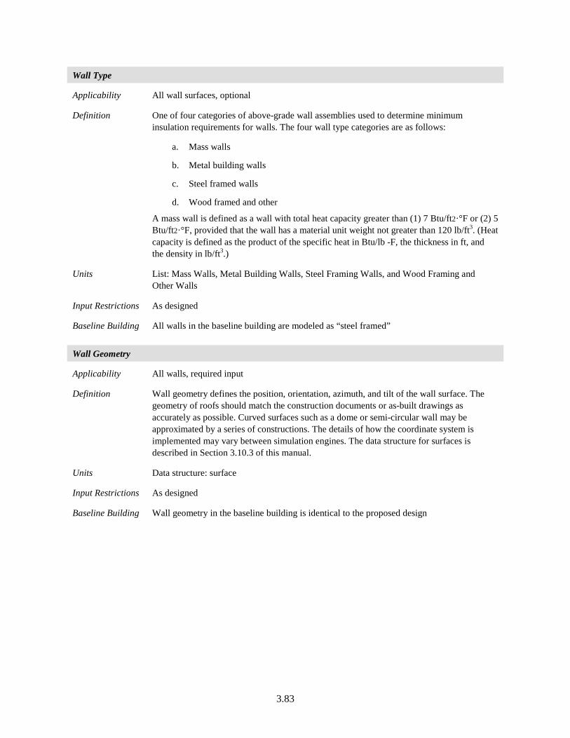
3.83
Wall Type
Applicability All wall surfaces, optional
Definition One of four categories of above-grade wall assemblies used to determine minimum insulation requirements for walls. The four wall type categories are as follows:
a. Mass walls
b. Metal building walls
c. Steel framed walls
d. Wood framed and other
A mass wall is defined as a wall with total heat capacity greater than (1) 7 Btu/ft2·°F or (2) 5 Btu/ft2·°F, provided that the wall has a material unit weight not greater than 120 lb/ft3. (Heat capacity is defined as the product of the specific heat in Btu/lb -F, the thickness in ft, and the density in lb/ft3.)
Units List: Mass Walls, Metal Building Walls, Steel Framing Walls, and Wood Framing and Other Walls
Input Restrictions As designed
Baseline Building All walls in the baseline building are modeled as “steel framed”
Wall Geometry
Applicability All walls, required input
Definition Wall geometry defines the position, orientation, azimuth, and tilt of the wall surface. The geometry of roofs should match the construction documents or as-built drawings as accurately as possible. Curved surfaces such as a dome or semi-circular wall may be approximated by a series of constructions. The details of how the coordinate system is implemented may vary between simulation engines. The data structure for surfaces is described in Section 3.10.3 of this manual.
Units Data structure: surface
Input Restrictions As designed
Baseline Building Wall geometry in the baseline building is identical to the proposed design
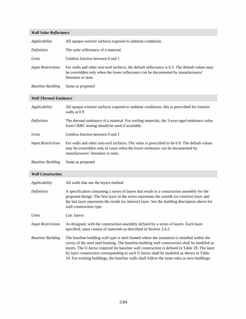
3.84
Wall Solar Reflectance
Applicability All opaque exterior surfaces exposed to ambient conditions
Definition The solar reflectance of a material
Units Unitless fraction between 0 and 1
Input Restrictions For walls and other non-roof surfaces, the default reflectance is 0.3. The default values may be overridden only when the lower reflectance can be documented by manufacturers’ literature or tests.
Baseline Building Same as proposed
Wall Thermal Emittance
Applicability All opaque exterior surfaces exposed to ambient conditions; this is prescribed for exterior walls at 0.9
Definition The thermal emittance of a material. For roofing materials, the 3-year-aged emittance value from CRRC testing should be used if available.
Units Unitless fraction between 0 and 1
Input Restrictions For walls and other non-roof surfaces: The value is prescribed to be 0.9. The default values may be overridden only in cases when the lower emittance can be documented by manufacturers’ literature or tests.
Baseline Building Same as proposed
Wall Construction
Applicability All walls that use the layers method
Definition A specification containing a series of layers that result in a construction assembly for the proposed design. The first layer in the series represents the outside (or exterior) layer and the last layer represents the inside (or interior) layer. See the building descriptors above for wall construction type.
Units List: layers
Input Restrictions As designed, with the construction assembly defined by a series of layers. Each layer specified, must consist of materials as described in Section 3.4.2.
Baseline Building The baseline building wall type is steel framed where the insulation is installed within the cavity of the steel stud framing. The baseline building wall construction shall be modeled as layers. The U-factor required for baseline wall construction is defined in Table 18. The layer by layer construction corresponding to each U-factor shall be modeled as shown in Table 19. For existing buildings, the baseline walls shall follow the same rules as new buildings.
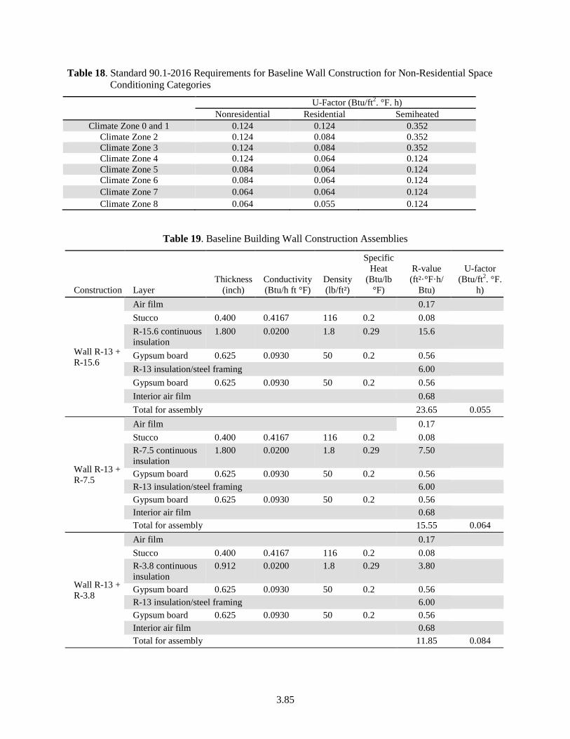
3.85
Table 18. Standard 90.1-2016 Requirements for Baseline Wall Construction for Non-Residential Space Conditioning Categories
U-Factor (Btu/ft2. °F. h) Nonresidential Residential Semiheated
Climate Zone 0 and 1 0.124 0.124 0.352 Climate Zone 2 0.124 0.084 0.352 Climate Zone 3 0.124 0.084 0.352 Climate Zone 4 0.124 0.064 0.124 Climate Zone 5 0.084 0.064 0.124 Climate Zone 6 0.084 0.064 0.124 Climate Zone 7 0.064 0.064 0.124 Climate Zone 8 0.064 0.055 0.124
Table 19. Baseline Building Wall Construction Assemblies
Construction Layer Thickness
(inch) Conductivity (Btu/h ft °F)
Density (lb/ft²)
Specific Heat
(Btu/lb °F)
R-value (ft²·°F·h/
Btu)
U-factor (Btu/ft2. °F.
h)
Wall R-13 + R-15.6
Air film 0.17 Stucco 0.400 0.4167 116 0.2 0.08 R-15.6 continuous insulation
1.800 0.0200 1.8 0.29 15.6
Gypsum board 0.625 0.0930 50 0.2 0.56 R-13 insulation/steel framing 6.00 Gypsum board 0.625 0.0930 50 0.2 0.56 Interior air film 0.68 Total for assembly 23.65 0.055
Wall R-13 + R-7.5
Air film 0.17 Stucco 0.400 0.4167 116 0.2 0.08 R-7.5 continuous insulation
1.800 0.0200 1.8 0.29 7.50
Gypsum board 0.625 0.0930 50 0.2 0.56 R-13 insulation/steel framing 6.00 Gypsum board 0.625 0.0930 50 0.2 0.56 Interior air film 0.68 Total for assembly 15.55 0.064
Wall R-13 + R-3.8
Air film 0.17 Stucco 0.400 0.4167 116 0.2 0.08 R-3.8 continuous insulation
0.912 0.0200 1.8 0.29 3.80
Gypsum board 0.625 0.0930 50 0.2 0.56 R-13 insulation/steel framing 6.00 Gypsum board 0.625 0.0930 50 0.2 0.56 Interior air film 0.68 Total for assembly 11.85 0.084
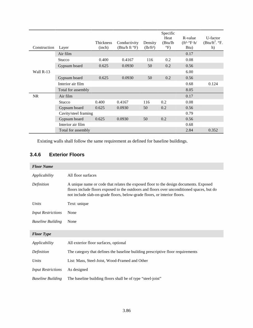
3.86
Construction Layer Thickness
(inch) Conductivity (Btu/h ft °F)
Density (lb/ft²)
Specific Heat
(Btu/lb °F)
R-value (ft²·°F·h/
Btu)
U-factor (Btu/ft2. °F.
h)
Wall R-13
Air film 0.17 Stucco 0.400 0.4167 116 0.2 0.08 Gypsum board 0.625 0.0930 50 0.2 0.56 6.00 Gypsum board 0.625 0.0930 50 0.2 0.56 Interior air film 0.68 0.124 Total for assembly 8.05
NR Air film 0.17 Stucco 0.400 0.4167 116 0.2 0.08 Gypsum board 0.625 0.0930 50 0.2 0.56 Cavity/steel framing 0.79 Gypsum board 0.625 0.0930 50 0.2 0.56 Interior air film 0.68 Total for assembly 2.84 0.352
Existing walls shall follow the same requirement as defined for baseline buildings.
3.4.6 Exterior Floors
Floor Name
Applicability All floor surfaces
Definition A unique name or code that relates the exposed floor to the design documents. Exposed floors include floors exposed to the outdoors and floors over unconditioned spaces, but do not include slab-on-grade floors, below-grade floors, or interior floors.
Units Text: unique
Input Restrictions None
Baseline Building None
Floor Type
Applicability All exterior floor surfaces, optional
Definition The category that defines the baseline building prescriptive floor requirements
Units List: Mass, Steel-Joist, Wood-Framed and Other
Input Restrictions As designed
Baseline Building The baseline building floors shall be of type “steel-joist”
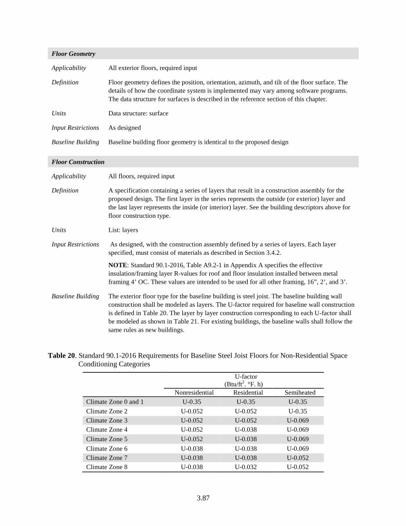
3.87
Floor Geometry
Applicability All exterior floors, required input
Definition Floor geometry defines the position, orientation, azimuth, and tilt of the floor surface. The details of how the coordinate system is implemented may vary among software programs. The data structure for surfaces is described in the reference section of this chapter.
Units Data structure: surface
Input Restrictions As designed
Baseline Building Baseline building floor geometry is identical to the proposed design
Floor Construction
Applicability All floors, required input
Definition A specification containing a series of layers that result in a construction assembly for the proposed design. The first layer in the series represents the outside (or exterior) layer and the last layer represents the inside (or interior) layer. See the building descriptors above for floor construction type.
Units List: layers
Input Restrictions As designed, with the construction assembly defined by a series of layers. Each layer specified, must consist of materials as described in Section 3.4.2.
NOTE: Standard 90.1-2016, Table A9.2-1 in Appendix A specifies the effective insulation/framing layer R-values for roof and floor insulation installed between metal framing 4’ OC. These values are intended to be used for all other framing, 16”, 2’, and 3’.
Baseline Building The exterior floor type for the baseline building is steel joist. The baseline building wall construction shall be modeled as layers. The U-factor required for baseline wall construction is defined in Table 20. The layer by layer construction corresponding to each U-factor shall be modeled as shown in Table 21. For existing buildings, the baseline walls shall follow the same rules as new buildings.
Table 20. Standard 90.1-2016 Requirements for Baseline Steel Joist Floors for Non-Residential Space Conditioning Categories
U-factor (Btu/ft2. °F. h)
Nonresidential Residential Semiheated Climate Zone 0 and 1 U-0.35 U-0.35 U-0.35 Climate Zone 2 U-0.052 U-0.052 U-0.35 Climate Zone 3 U-0.052 U-0.052 U-0.069 Climate Zone 4 U-0.052 U-0.038 U-0.069 Climate Zone 5 U-0.052 U-0.038 U-0.069 Climate Zone 6 U-0.038 U-0.038 U-0.069 Climate Zone 7 U-0.038 U-0.038 U-0.052 Climate Zone 8 U-0.038 U-0.032 U-0.052
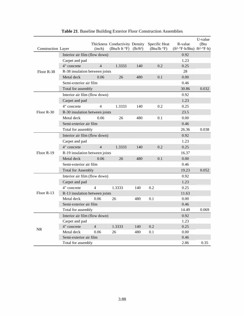
3.88
Table 21. Baseline Building Exterior Floor Construction Assemblies
Construction Layer Thickness
(inch) Conductivity (Btu/h ft °F)
Density (lb/ft²)
Specific Heat (Btu/lb °F)
R-value (ft²·°F·h/Btu)
U-value (Btu
/ft²·°F·h)
Floor R-38
Interior air film (flow down) 0.92 Carpet and pad 1.23 4" concrete 4 1.3333 140 0.2 0.25 R-38 insulation between joists 28 Metal deck 0.06 26 480 0.1 0.00 Semi-exterior air film 0.46 Total for assembly 30.86 0.032
Floor R-30
Interior air film (flow down) 0.92 Carpet and pad 1.23 4" concrete 4 1.3333 140 0.2 0.25 R-30 insulation between joists 23.5 Metal deck 0.06 26 480 0.1 0.00 Semi-exterior air film 0.46 Total for assembly 26.36 0.038
Floor R-19
Interior air film (flow down) 0.92 Carpet and pad 1.23 4" concrete 4 1.3333 140 0.2 0.25 R-19 insulation between joists 16.37 Metal deck 0.06 26 480 0.1 0.00 Semi-exterior air film 0.46 Total for Assembly 19.23 0.052
Floor R-13
Interior air film (flow down) 0.92 Carpet and pad 1.23 4" concrete 4 1.3333 140 0.2 0.25 R-13 insulation between joists 11.63 Metal deck 0.06 26 480 0.1 0.00 Semi-exterior air film 0.46 Total for assembly 14.49 0.069
NR
Interior air film (flow down) 0.92 Carpet and pad 1.23 4" concrete 4 1.3333 140 0.2 0.25 Metal deck 0.06 26 480 0.1 0.00 Semi-exterior air film 0.46 Total for assembly 2.86 0.35
3.89
3.4.7 Doors
Door Name
Applicability All exterior doors, optional input
Definition A unique name or code that relates the door to the design documents submitted. Doors that are more than 50% glass are treated as windows and must be determined and entered by using the fenestration building descriptors.
Units Text: unique
Input Restrictions None
Baseline Building None
Door Type
Applicability All exterior doors, required input
Definition For the purposes of determining building envelope requirements, the classifications are defined as follows:
1. Non-swinging: roll-up, metal coiling, sliding, and all other doors that are not swinging doors.
2. Swinging: all operable opaque panels with hinges on one side and opaque revolving doors. The prescriptive U-factor requirements depend on door type and climate. This building descriptor may be derived from other building descriptors, in which case a specific input is not necessary.
Units List: Swinging or Non-swinging
Input Restrictions The door type shall be consistent with the type of door represented on the construction documents or as-built drawings
Baseline Building The baseline building door type shall be the same as the proposed design
Door Geometry
Applicability All exterior doors
Definition Door geometry defines the position and dimensions of the door surface relative to its parent wall surface. The azimuth and tilt (if any) of the door are inherited from the parent surface. The position of the door within the parent surface is specified through X,Y coordinates. The size is specified as a height and width (all doors are generally assumed to be rectangular). The details of how the geometry of doors is specified may vary for each energy simulation program.
Units Data structure: opening
Input Restrictions As designed
Baseline Building Door geometry in the baseline building is identical to the proposed design
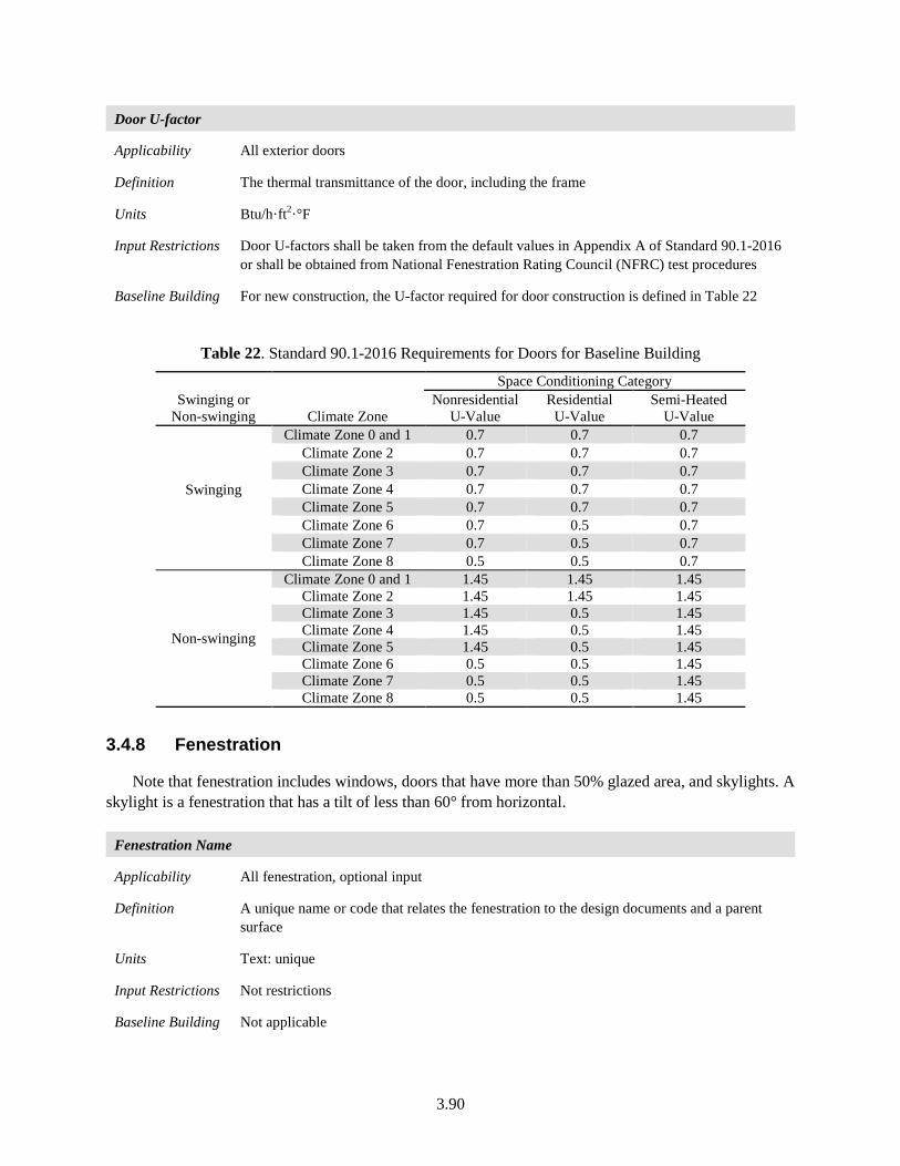
3.90
Door U-factor
Applicability All exterior doors
Definition The thermal transmittance of the door, including the frame
Units Btu/h·ft2·°F
Input Restrictions Door U-factors shall be taken from the default values in Appendix A of Standard 90.1-2016 or shall be obtained from National Fenestration Rating Council (NFRC) test procedures
Baseline Building For new construction, the U-factor required for door construction is defined in Table 22
Table 22. Standard 90.1-2016 Requirements for Doors for Baseline Building
Swinging or Non-swinging Climate Zone
Space Conditioning Category Nonresidential
U-Value Residential
U-Value Semi-Heated
U-Value
Swinging
Climate Zone 0 and 1 0.7 0.7 0.7 Climate Zone 2 0.7 0.7 0.7 Climate Zone 3 0.7 0.7 0.7 Climate Zone 4 0.7 0.7 0.7 Climate Zone 5 0.7 0.7 0.7 Climate Zone 6 0.7 0.5 0.7 Climate Zone 7 0.7 0.5 0.7 Climate Zone 8 0.5 0.5 0.7
Non-swinging
Climate Zone 0 and 1 1.45 1.45 1.45 Climate Zone 2 1.45 1.45 1.45 Climate Zone 3 1.45 0.5 1.45 Climate Zone 4 1.45 0.5 1.45 Climate Zone 5 1.45 0.5 1.45 Climate Zone 6 0.5 0.5 1.45 Climate Zone 7 0.5 0.5 1.45 Climate Zone 8 0.5 0.5 1.45
3.4.8 Fenestration
Note that fenestration includes windows, doors that have more than 50% glazed area, and skylights. A skylight is a fenestration that has a tilt of less than 60° from horizontal.
Fenestration Name
Applicability All fenestration, optional input
Definition A unique name or code that relates the fenestration to the design documents and a parent surface
Units Text: unique
Input Restrictions Not restrictions
Baseline Building Not applicable
3.91
Vertical Fenestration Geometry and Area
Applicability All fenestration
Definition Fenestration geometry defines the position and dimensions of the fenestration surface within its parent surface and the identification of the parent surface. The orientation and tilt are inherited from the parent surface. The details of how the coordinate system is implemented may vary between software programs.
Units Data structure: opening
Input Restrictions As designed. The defined fenestration should match with the construction drawings or as-built drawings.
Specification of the fenestration position within its parent surface is required for the following conditions:
• Exterior shading is modeled from buildings, vegetation, and other objects. All elements whose effective height is greater than their distance from a proposed building and whose width facing the proposed building is greater than one-third that of the proposed building shall be accounted for in the analysis
• If daylighting is modeled within the adjacent space.
Baseline Building The geometry of the vertical fenestration shall be similar to the proposed design but each fenestration shall be increased or reduced in size in proportion to the proposed design size such that the overall fenestration area as a percentage of the above-grade exterior wall area is equal to the values in Table 23. For building areas not shown in Table 23, vertical fenestration areas shall equal that in the proposed design or 40% of gross above-grade wall area, whichever is smaller, and shall be distributed on each face of the building in the same proportions in the proposed design.
If the gross area of all windows (including framing) in each space conditioning category in the building exceeds the value specified in Table 23 of the gross above-grade exterior wall area for that building area type, the dimensions of each window shall be reduced such that the window to wall ration is equal to the value specified in Table 23. This reduction needs to be done by increasing the sill height until the limit is reached for each building area type.
If the WWR of the proposed building design is less than the value specified in Table 23, the dimensions of each window shall be increased equally from the center of the window until a wall or partition is reached. If window area needs to be increased further, then the sill height will be reduced will the maximum WWR limit is reached.
The fenestration area for an existing building shall equal the existing fenestration area prior to the proposed work and shall be distributed on each face of the building in the same proportions as the existing building.
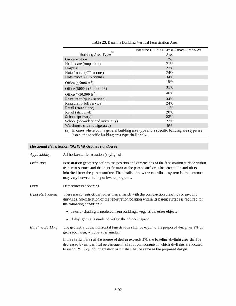
3.92
Table 23. Baseline Building Vertical Fenestration Area
Building Area Types(a)
Baseline Building Gross Above-Grade-Wall
Area Grocery Store 7% Healthcare (outpatient) 21% Hospital 27% Hotel/motel (≤75 rooms) 24% Hotel/motel (>75 rooms) 34% Office (≤5000 ft2) 19%
Office (5000 to 50,000 ft2) 31%
Office (>50,000 ft2) 40% Restaurant (quick service) 34% Restaurant (full service) 24% Retail (standalone) 11% Retail (strip mall) 20% School (primary) 22% School (secondary and university) 22% Warehouse (non-refrigerated) 6% (a) In cases where both a general building area type and a specific building area type are
listed, the specific building area type shall apply.
Horizontal Fenestration (Skylight) Geometry and Area
Applicability All horizontal fenestration (skylights)
Definition Fenestration geometry defines the position and dimensions of the fenestration surface within its parent surface and the identification of the parent surface. The orientation and tilt is inherited from the parent surface. The details of how the coordinate system is implemented may vary between rating software programs.
Units Data structure: opening
Input Restrictions There are no restrictions, other than a match with the construction drawings or as-built drawings. Specification of the fenestration position within its parent surface is required for the following conditions:
• exterior shading is modeled from buildings, vegetation, other objects
• if daylighting is modeled within the adjacent space.
Baseline Building The geometry of the horizontal fenestration shall be equal to the proposed design or 3% of gross roof area, whichever is smaller.
If the skylight area of the proposed design exceeds 3%, the baseline skylight area shall be decreased by an identical percentage in all roof components in which skylights are located to reach 3%. Skylight orientation as tilt shall be the same as the proposed design.
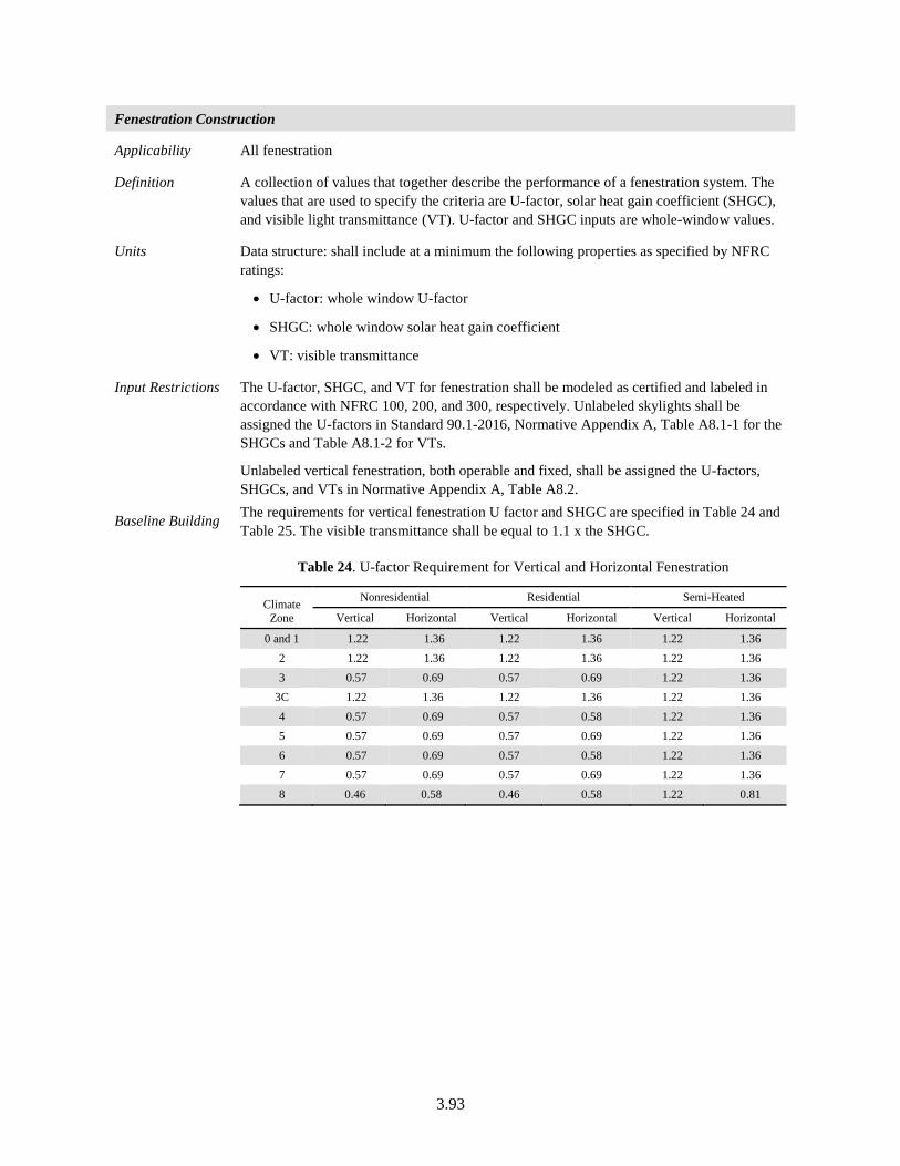
3.93
Fenestration Construction
Applicability All fenestration
Definition A collection of values that together describe the performance of a fenestration system. The values that are used to specify the criteria are U-factor, solar heat gain coefficient (SHGC), and visible light transmittance (VT). U-factor and SHGC inputs are whole-window values.
Units Data structure: shall include at a minimum the following properties as specified by NFRC ratings:
• U-factor: whole window U-factor
• SHGC: whole window solar heat gain coefficient
• VT: visible transmittance
Input Restrictions The U-factor, SHGC, and VT for fenestration shall be modeled as certified and labeled in accordance with NFRC 100, 200, and 300, respectively. Unlabeled skylights shall be assigned the U-factors in Standard 90.1-2016, Normative Appendix A, Table A8.1-1 for the SHGCs and Table A8.1-2 for VTs.
Unlabeled vertical fenestration, both operable and fixed, shall be assigned the U-factors, SHGCs, and VTs in Normative Appendix A, Table A8.2.
Baseline Building The requirements for vertical fenestration U factor and SHGC are specified in Table 24 and Table 25. The visible transmittance shall be equal to 1.1 x the SHGC.
Table 24. U-factor Requirement for Vertical and Horizontal Fenestration
Climate Zone
Nonresidential Residential Semi-Heated
Vertical Horizontal Vertical Horizontal Vertical Horizontal
0 and 1 1.22 1.36 1.22 1.36 1.22 1.36 2 1.22 1.36 1.22 1.36 1.22 1.36 3 0.57 0.69 0.57 0.69 1.22 1.36
3C 1.22 1.36 1.22 1.36 1.22 1.36 4 0.57 0.69 0.57 0.58 1.22 1.36 5 0.57 0.69 0.57 0.69 1.22 1.36 6 0.57 0.69 0.57 0.58 1.22 1.36 7 0.57 0.69 0.57 0.69 1.22 1.36 8 0.46 0.58 0.46 0.58 1.22 0.81
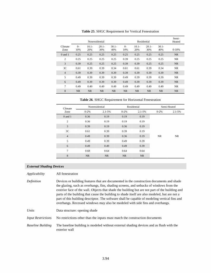
3.94
Table 25. SHGC Requirement for Vertical Fenestration
Climate Zone
Nonresidential Residential Semi-Heated
0-10%
10.1-20%
20.1-30%
30.1-40%
0-10%
10.1-20%
20.1-30%
30.1-40% 0-10%
0 and 1 0.25 0.25 0.25 0.25 0.25 0.25 0.25 0.25 NR 2 0.25 0.25 0.25 0.25 0.39 0.25 0.25 0.25 NR 3 0.39 0.25 0.25 0.25 0.39 0.39 0.25 0.25 NR
3C 0.61 0.39 0.39 0.34 0.61 0.61 0.39 0.34 NR 4 0.39 0.39 0.39 0.39 0.39 0.39 0.39 0.39 NR 5 0.49 0.39 0.39 0.39 0.49 0.39 0.39 0.39 NR 6 0.49 0.39 0.39 0.39 0.49 0.39 0.39 0.39 NR 7 0.49 0.49 0.49 0.49 0.49 0.49 0.49 0.49 NR 8 NR NR NR NR NR NR NR NR NR
Table 26. SHGC Requirement for Horizontal Fenestration
Climate Zone
Nonresidential Residential Semi-Heated
0-2% 2.1-5% 0-2% 2.1-5% 0-2% 2.1-5%
0 and 1 0.36 0.19 0.19 0.19
NR NR
2 0.36 0.19 0.19 0.19
3 0.39 0.19 0.36 0.19
3C 0.61 0.39 0.39 0.19
4 0.49 0.39 0.36 0.19
5 0.49 0.39 0.49 0.39
6 0.49 0.49 0.49 0.39
7 0.68 0.64 0.64 0.64
8 NR NR NR NR
External Shading Devices
Applicability All fenestration
Definition Devices or building features that are documented in the construction documents and shade the glazing, such as overhangs, fins, shading screens, and setbacks of windows from the exterior face of the wall. Objects that shade the building but are not part of the building and parts of the building that cause the building to shade itself are also modeled, but are not a part of this building descriptor. The software shall be capable of modeling vertical fins and overhangs. Recessed windows may also be modeled with side fins and overhangs.
Units Data structure: opening shade
Input Restrictions No restrictions other than the inputs must match the construction documents
Baseline Building The baseline building is modeled without external shading devices and as flush with the exterior wall
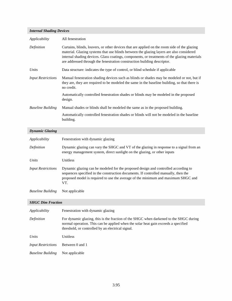
3.95
Internal Shading Devices
Applicability All fenestration
Definition Curtains, blinds, louvers, or other devices that are applied on the room side of the glazing material. Glazing systems that use blinds between the glazing layers are also considered internal shading devices. Glass coatings, components, or treatments of the glazing materials are addressed through the fenestration construction building descriptor.
Units Data structure: indicates the type of control, or blind schedule if applicable
Input Restrictions Manual fenestration shading devices such as blinds or shades may be modeled or not, but if they are, they are required to be modeled the same in the baseline building, so that there is no credit.
Automatically controlled fenestration shades or blinds may be modeled in the proposed design.
Baseline Building Manual shades or blinds shall be modeled the same as in the proposed building.
Automatically controlled fenestration shades or blinds will not be modeled in the baseline building.
Dynamic Glazing
Applicability Fenestration with dynamic glazing
Definition Dynamic glazing can vary the SHGC and VT of the glazing in response to a signal from an energy management system, direct sunlight on the glazing, or other inputs
Units Unitless
Input Restrictions Dynamic glazing can be modeled for the proposed design and controlled according to sequences specified in the construction documents. If controlled manually, then the proposed model is required to use the average of the minimum and maximum SHGC and VT.
Baseline Building Not applicable
SHGC Dim Fraction
Applicability Fenestration with dynamic glazing
Definition For dynamic glazing, this is the fraction of the SHGC when darkened to the SHGC during normal operation. This can be applied when the solar heat gain exceeds a specified threshold, or controlled by an electrical signal.
Units Unitless
Input Restrictions Between 0 and 1
Baseline Building Not applicable
3.96
VT Dim Fraction
Applicability Fenestration with dynamic glazing
Definition For dynamic glazing, this is the fraction of the visible transmittance when darkened to the visible transmittance during normal operation. This can be applied when the solar heat gain exceeds a specified threshold, or controlled by an electrical signal.
Units Unitless
Input Restrictions Between 0 and 1
Baseline Building Not applicable
Dynamic Solar Heat Gain Threshold
Applicability Fenestration with automatically controlled dynamic glazing
Definition For dynamic glazing, this is the solar heat gain threshold above which the dynamic glazing is active (darkened). When the solar heat gain drops below this threshold, the glazing is switched back to being inactive (clearest setting). Indoor and outdoor air temperatures (OATs) can also be used as setpoints for controlling the switchable solar heat gain threshold. This may be used in combination with the solar heat gain and illuminance thresholds for control. A flag may be used to indicate that this control is not used.
Units Incident solar threshold (Btu/h-ft2)
Input Restrictions As designed
Baseline Building Not applicable
Switchable Space Temperature Threshold
Applicability Fenestration with automatically controlled dynamic glazing
Definition For dynamic glazing, this is the space temperature above which the dynamic glazing is active (darkened). When the space temperature drops below this threshold, the glazing is switched back to being inactive (clearest setting). Indoor and outdoor air temperatures are the setpoints required for controlling the dynamic solar heat gain threshold. This may be used in combination with the solar heat gain and illuminance thresholds for control. A flag may be used to indicate that this control is not used.
Units °F
Input Restrictions As designed
Baseline Building Not applicable
3.97
Dynamic Illuminance Threshold
Applicability Fenestration with automatically controlled dynamic glazing
Definition For dynamic glazing, this is the illuminance threshold above which the dynamic glazing is regulated between active (darkened) and inactive (clearest setting). With a single illuminance setpoint, the dynamic glazing will adjust between the clearest and darkest setting to allow the desired illuminance level. A flag may be used to indicate that this control is not used.
Units lux
Input Restrictions As designed
Baseline Building Not applicable
Dynamic Glazing Schedule
Applicability Fenestration with dynamic glazing controlled by an electrical signal
Definition For dynamic glazing, this is an hourly schedule for when the dynamic glazing is darkened, when controlled by an electrical signal
Units Boolean: 1 if dynamic glazing is active (darkened); 0 if not active
Input Restrictions 0 or 1 for schedule values. As designed.
Baseline Building Not applicable
3.4.9 Below-Grade Walls
Below-Grade Wall Name
Applicability All projects, optional input
Definition A unique name that keys the below-grade wall to the construction documents
Units Text: unique
Input Restrictions None
Baseline Building Not applicable
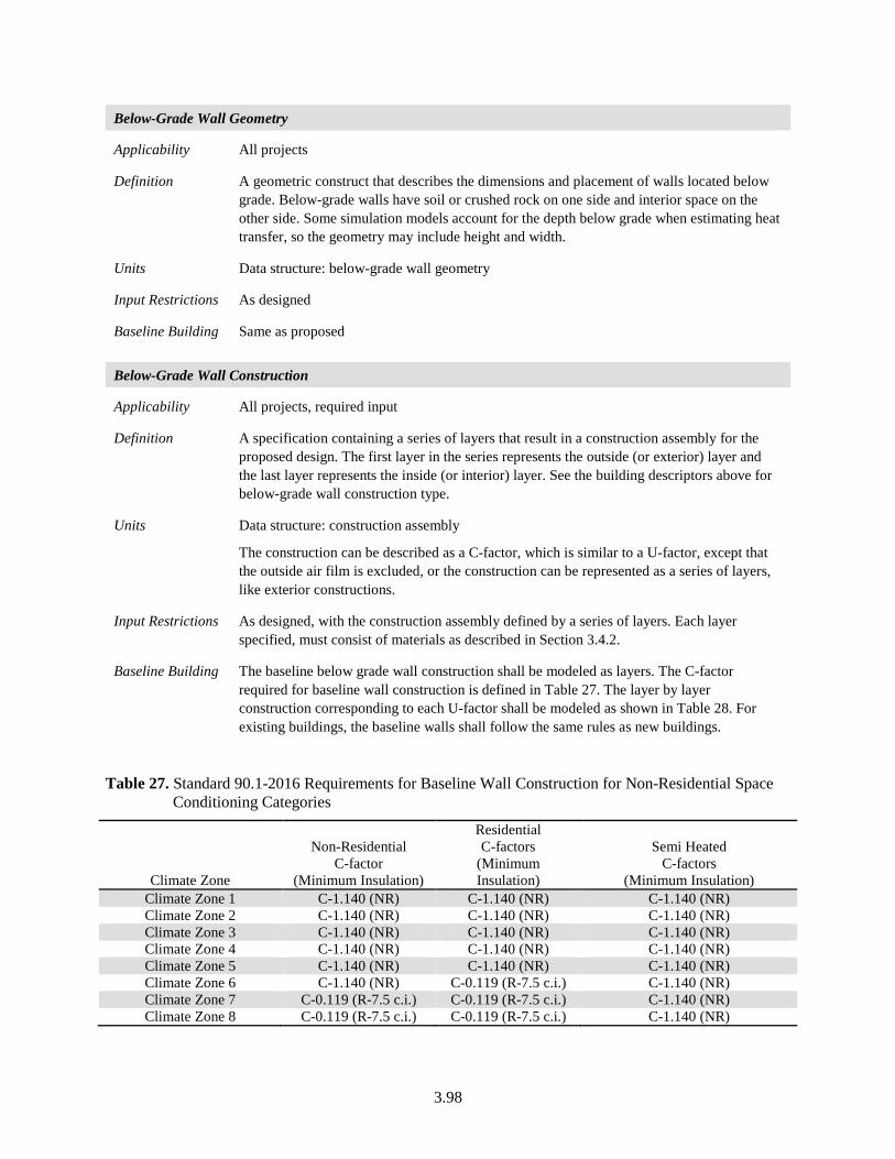
3.98
Below-Grade Wall Geometry
Applicability All projects
Definition A geometric construct that describes the dimensions and placement of walls located below grade. Below-grade walls have soil or crushed rock on one side and interior space on the other side. Some simulation models account for the depth below grade when estimating heat transfer, so the geometry may include height and width.
Units Data structure: below-grade wall geometry
Input Restrictions As designed
Baseline Building Same as proposed
Below-Grade Wall Construction
Applicability All projects, required input
Definition A specification containing a series of layers that result in a construction assembly for the proposed design. The first layer in the series represents the outside (or exterior) layer and the last layer represents the inside (or interior) layer. See the building descriptors above for below-grade wall construction type.
Units Data structure: construction assembly
The construction can be described as a C-factor, which is similar to a U-factor, except that the outside air film is excluded, or the construction can be represented as a series of layers, like exterior constructions.
Input Restrictions As designed, with the construction assembly defined by a series of layers. Each layer specified, must consist of materials as described in Section 3.4.2.
Baseline Building The baseline below grade wall construction shall be modeled as layers. The C-factor required for baseline wall construction is defined in Table 27. The layer by layer construction corresponding to each U-factor shall be modeled as shown in Table 28. For existing buildings, the baseline walls shall follow the same rules as new buildings.
Table 27. Standard 90.1-2016 Requirements for Baseline Wall Construction for Non-Residential Space Conditioning Categories
Climate Zone
Non-Residential C-factor
(Minimum Insulation)
Residential C-factors
(Minimum Insulation)
Semi Heated C-factors
(Minimum Insulation) Climate Zone 1 C-1.140 (NR) C-1.140 (NR) C-1.140 (NR) Climate Zone 2 C-1.140 (NR) C-1.140 (NR) C-1.140 (NR) Climate Zone 3 C-1.140 (NR) C-1.140 (NR) C-1.140 (NR) Climate Zone 4 C-1.140 (NR) C-1.140 (NR) C-1.140 (NR) Climate Zone 5 C-1.140 (NR) C-1.140 (NR) C-1.140 (NR) Climate Zone 6 C-1.140 (NR) C-0.119 (R-7.5 c.i.) C-1.140 (NR) Climate Zone 7 C-0.119 (R-7.5 c.i.) C-0.119 (R-7.5 c.i.) C-1.140 (NR) Climate Zone 8 C-0.119 (R-7.5 c.i.) C-0.119 (R-7.5 c.i.) C-1.140 (NR)
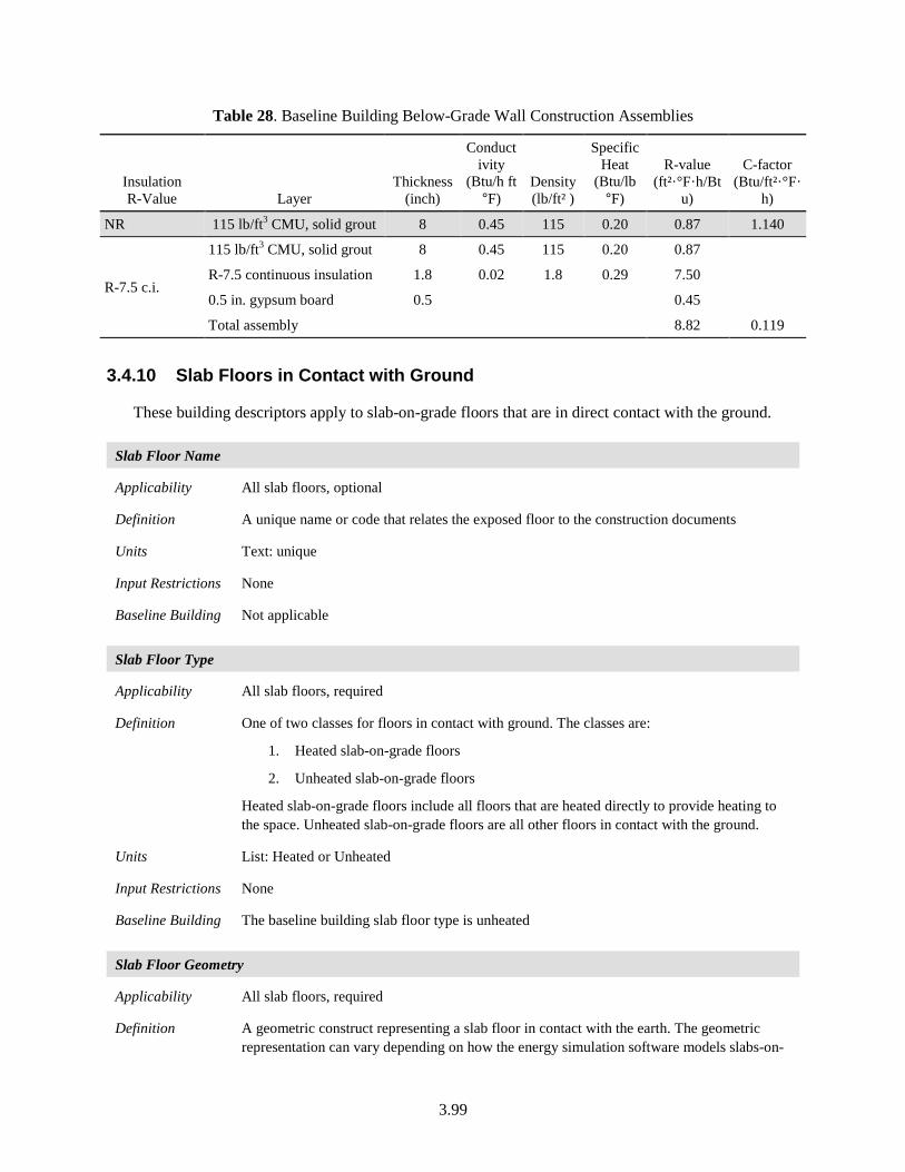
3.99
Table 28. Baseline Building Below-Grade Wall Construction Assemblies
Insulation R-Value Layer
Thickness (inch)
Conductivity
(Btu/h ft °F)
Density (lb/ft² )
Specific Heat
(Btu/lb °F)
R-value (ft²·°F·h/Bt
u)
C-factor (Btu/ft²·°F·
h)
NR 115 lb/ft3 CMU, solid grout 8 0.45 115 0.20 0.87 1.140
R-7.5 c.i.
115 lb/ft3 CMU, solid grout 8 0.45 115 0.20 0.87
R-7.5 continuous insulation 1.8 0.02 1.8 0.29 7.50
0.5 in. gypsum board 0.5 0.45
Total assembly 8.82 0.119
3.4.10 Slab Floors in Contact with Ground
These building descriptors apply to slab-on-grade floors that are in direct contact with the ground.
Slab Floor Name
Applicability All slab floors, optional
Definition A unique name or code that relates the exposed floor to the construction documents
Units Text: unique
Input Restrictions None
Baseline Building Not applicable
Slab Floor Type
Applicability All slab floors, required
Definition One of two classes for floors in contact with ground. The classes are:
1. Heated slab-on-grade floors
2. Unheated slab-on-grade floors
Heated slab-on-grade floors include all floors that are heated directly to provide heating to the space. Unheated slab-on-grade floors are all other floors in contact with the ground.
Units List: Heated or Unheated
Input Restrictions None
Baseline Building The baseline building slab floor type is unheated
Slab Floor Geometry
Applicability All slab floors, required
Definition A geometric construct representing a slab floor in contact with the earth. The geometric representation can vary depending on how the energy simulation software models slabs-on-
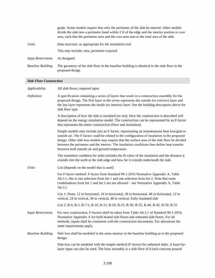
3.100
grade. Some models require that only the perimeter of the slab be entered. Other models divide the slab into a perimeter band within 2 ft of the edge and the interior portion or core area, such that the perimeter area and the core area sum to the total area of the slab.
Units Data structure: as appropriate for the simulation tool
This may include: area, perimeter exposed
Input Restrictions As designed
Baseline Building The geometry of the slab floor in the baseline building is identical to the slab floor in the proposed design
Slab Floor Construction
Applicability All slab floors, required input
Definition A specification containing a series of layers that result in a construction assembly for the proposed design. The first layer in the series represents the outside (or exterior) layer and the last layer represents the inside (or interior) layer. See the building descriptors above for slab floor type.
A description of how the slab is insulated (or not). How the construction is described will depend on the energy simulation model. The construction can be represented by an F-factor that represents the entire construction (floor and insulation).
Simple models may include just an F-factor, representing an instantaneous heat loss/gain to outside air. The F-factor could be related to the configuration of insulation in the proposed design. Other slab loss models may require that the surface area of the slab floor be divided between the perimeter and the interior. The insulation conditions then define heat transfer between both outside air and ground temperature.
The insulation condition for slabs includes the R-value of the insulation and the distance it extends into the earth at the slab edge and how far it extends underneath the slab.
Units List (depends on the model that is used)
For F-factor method: F-factor from Standard 90.1-2016 Normative Appendix A, Table A6.3.1; this is one selection from list 1 and one selection from list 2. Note that some combinations from list 1 and list 2 are not allowed – see Normative Appendix A, Table A6.3.1.
List 1: None, 12 in horizontal, 24 in horizontal, 36 in horizontal, 48 in horizontal, 12 in vertical, 24 in vertical, 36 in vertical, 48 in vertical, Fully insulated slab
List 2: R-0, R-5, R-7.5, R-10, R-15, R-20, R-25, R-30, R-35, R-40, R-45, R-50, R-55
Input Restrictions For new construction, F-factors shall be taken from Table A6.3.1 of Standard 90.1-2016, Normative Appendix A for both heated slab floors and unheated slab floors. For all methods, inputs shall be consistent with the construction documents. For alterations the same requirements apply.
Baseline Building Slab loss shall be modeled in the same manner in the baseline building as in the proposed design.
Slab loss can be modeled with the simple method (F-factor) for unheated slabs. A layer-by-layer input can also be used. The base assembly is a slab floor of 6-inch concrete poured
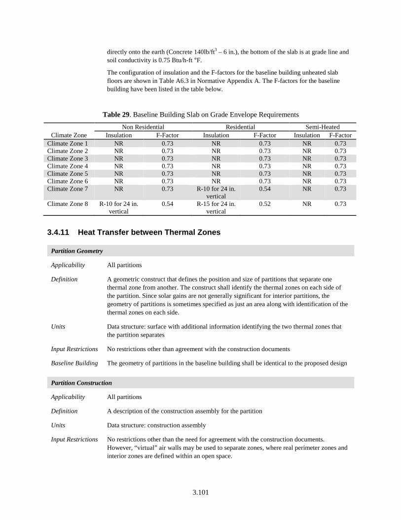
3.101
directly onto the earth (Concrete 140lb/ft3 – 6 in.), the bottom of the slab is at grade line and soil conductivity is 0.75 Btu/h-ft °F.
The configuration of insulation and the F-factors for the baseline building unheated slab floors are shown in Table A6.3 in Normative Appendix A. The F-factors for the baseline building have been listed in the table below.
Table 29. Baseline Building Slab on Grade Envelope Requirements
Climate Zone Non Residential Residential Semi-Heated
Insulation F-Factor Insulation F-Factor Insulation F-Factor Climate Zone 1 NR 0.73 NR 0.73 NR 0.73 Climate Zone 2 NR 0.73 NR 0.73 NR 0.73 Climate Zone 3 NR 0.73 NR 0.73 NR 0.73 Climate Zone 4 NR 0.73 NR 0.73 NR 0.73 Climate Zone 5 NR 0.73 NR 0.73 NR 0.73 Climate Zone 6 NR 0.73 NR 0.73 NR 0.73 Climate Zone 7 NR 0.73 R-10 for 24 in.
vertical 0.54 NR 0.73
Climate Zone 8 R-10 for 24 in. vertical
0.54 R-15 for 24 in. vertical
0.52 NR 0.73
3.4.11 Heat Transfer between Thermal Zones
Partition Geometry
Applicability All partitions
Definition A geometric construct that defines the position and size of partitions that separate one thermal zone from another. The construct shall identify the thermal zones on each side of the partition. Since solar gains are not generally significant for interior partitions, the geometry of partitions is sometimes specified as just an area along with identification of the thermal zones on each side.
Units Data structure: surface with additional information identifying the two thermal zones that the partition separates
Input Restrictions No restrictions other than agreement with the construction documents
Baseline Building The geometry of partitions in the baseline building shall be identical to the proposed design
Partition Construction
Applicability All partitions
Definition A description of the construction assembly for the partition
Units Data structure: construction assembly
Input Restrictions No restrictions other than the need for agreement with the construction documents. However, “virtual” air walls may be used to separate zones, where real perimeter zones and interior zones are defined within an open space.
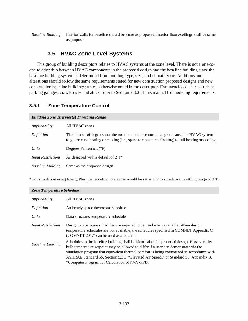
3.102
Baseline Building Interior walls for baseline should be same as proposed. Interior floors/ceilings shall be same as proposed
3.5 HVAC Zone Level Systems
This group of building descriptors relates to HVAC systems at the zone level. There is not a one-to-one relationship between HVAC components in the proposed design and the baseline building since the baseline building system is determined from building type, size, and climate zone. Additions and alterations should follow the same requirements stated for new construction proposed designs and new construction baseline buildings; unless otherwise noted in the descriptor. For unenclosed spaces such as parking garages, crawlspaces and attics, refer to Section 2.3.3 of this manual for modeling requirements.
3.5.1 Zone Temperature Control
Building Zone Thermostat Throttling Range
Applicability All HVAC zones
Definition The number of degrees that the room temperature must change to cause the HVAC system to go from no heating or cooling (i.e., space temperatures floating) to full heating or cooling
Units Degrees Fahrenheit (°F)
Input Restrictions As designed with a default of 2°F*
Baseline Building Same as the proposed design
* For simulation using EnergyPlus, the reporting tolerances would be set as 1°F to simulate a throttling range of 2°F.
Zone Temperature Schedule
Applicability All HVAC zones
Definition An hourly space thermostat schedule
Units Data structure: temperature schedule
Input Restrictions Design temperature schedules are required to be used when available. When design temperature schedules are not available, the schedules specified in COMNET Appendix C (COMNET 2017) can be used as a default.
Baseline Building Schedules in the baseline building shall be identical to the proposed design. However, dry bulb temperature setpoint may be allowed to differ if a user can demonstrate via the simulation program that equivalent thermal comfort is being maintained in accordance with ASHRAE Standard 55, Section 5.3.3, “Elevated Air Speed,” or Standard 55, Appendix B, “Computer Program for Calculation of PMV-PPD.”

3.103
3.5.2 Terminal Device Data
Terminal Type
Applicability All HVAC zones
Definition A terminal unit includes any device serving a zone (or group of zones collected in a thermal zone) that has the ability to reheat or re-cool in response to the zone thermostat. This includes:
• None (the case for single zone units)
• VAV box
• Series fan-powered VAV box
• Parallel fan-powered VAV box
• Induction-type VAV box
• Dual-duct mixing box (constant volume and VAV)
• Two- and three-duct mixing dampers (multi-zone systems)
• Reheat coil (constant volume systems)
• Perimeter induction units
• Chilled beams
• Radiant heating and cooling
• Fan coil units
• Variable refrigerant flow terminal units
Units List (see above)
Input Restrictions As designed
Baseline Building Table 30 specifies the HVAC terminal device for each of the baseline building systems. See Table 3 for a summary of the HVAC mapping.
Table 30. Baseline Building HVAC Terminal Devices
Baseline System HVAC Terminal Type Baseline Building System Terminal Type
System 1 PTAC None System 2 PTHP None System 3 PSZ AC None System 4 PSZ HP None System 5 PVAV reheat VAV with hot water reheat System 6 Packaged VAV with PFP boxes Parallel fan-powered boxes with electric reheat System 7 VAV with Reheat VAV with hot water reheat System 8 VAV with PFP boxes Parallel fan-powered boxes with electric reheat System 9 Heating and ventilation None
System 10 Heating and ventilation None System 11 SZ-VAV None System 12 SZ-CV-HW None System 13 SZ-CV-ER None
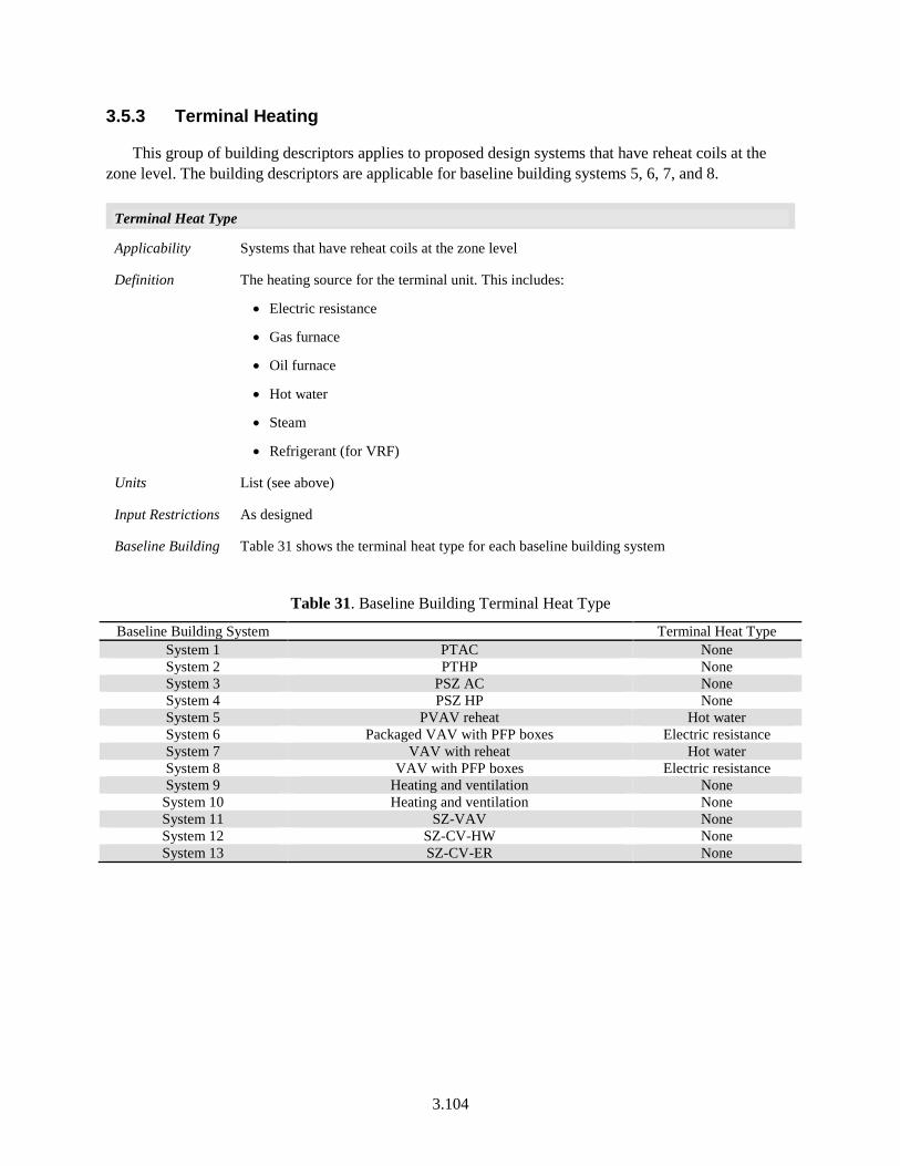
3.104
3.5.3 Terminal Heating
This group of building descriptors applies to proposed design systems that have reheat coils at the zone level. The building descriptors are applicable for baseline building systems 5, 6, 7, and 8.
Terminal Heat Type
Applicability Systems that have reheat coils at the zone level
Definition The heating source for the terminal unit. This includes:
• Electric resistance
• Gas furnace
• Oil furnace
• Hot water
• Steam
• Refrigerant (for VRF)
Units List (see above)
Input Restrictions As designed
Baseline Building Table 31 shows the terminal heat type for each baseline building system
Table 31. Baseline Building Terminal Heat Type
Baseline Building System Terminal Heat Type System 1 PTAC None System 2 PTHP None System 3 PSZ AC None System 4 PSZ HP None System 5 PVAV reheat Hot water System 6 Packaged VAV with PFP boxes Electric resistance System 7 VAV with reheat Hot water System 8 VAV with PFP boxes Electric resistance System 9 Heating and ventilation None
System 10 Heating and ventilation None System 11 SZ-VAV None System 12 SZ-CV-HW None System 13 SZ-CV-ER None
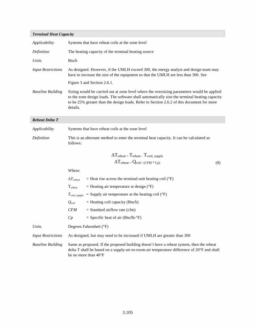
3.105
Terminal Heat Capacity
Applicability Systems that have reheat coils at the zone level
Definition The heating capacity of the terminal heating source
Units Btu/h
Input Restrictions As designed. However, if the UMLH exceed 300, the energy analyst and design team may have to increase the size of the equipment so that the UMLH are less than 300. See
Figure 3 and Section 2.6.1.
Baseline Building Sizing would be carried out at zone level where the oversizing parameters would be applied to the zone design loads. The software shall automatically size the terminal heating capacity to be 25% greater than the design loads. Refer to Section 2.6.2 of this document for more details.
Reheat Delta T
Applicability Systems that have reheat coils at the zone level
Definition This is an alternate method to enter the terminal heat capacity. It can be calculated as follows:
∆Treheat = Treheat - Tcool_supply
∆Treheat = Qcoil / (CFM * Cp) (8)
Where:
∆Treheat = Heat rise across the terminal unit heating coil (°F)
Treheat = Heating air temperature at design (°F)
Tcool_supply = Supply air temperature at the heating coil (°F)
Qcoil = Heating coil capacity (Btu/h)
CFM = Standard airflow rate (cfm)
Cp = Specific heat of air (Btu/lb-°F)
Units Degrees Fahrenheit (°F)
Input Restrictions As designed, but may need to be increased if UMLH are greater than 300
Baseline Building Same as proposed. If the proposed building doesn’t have a reheat system, then the reheat delta T shall be based on a supply-air-to-room-air temperature difference of 20°F and shall be no more than 40°F
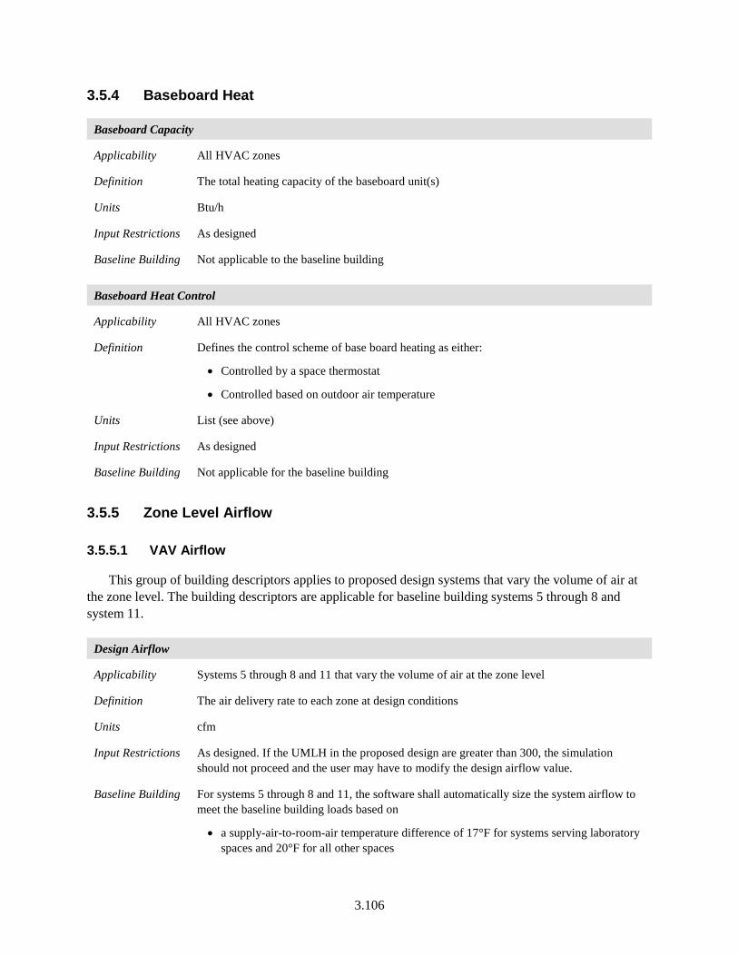
3.106
3.5.4 Baseboard Heat
Baseboard Capacity
Applicability All HVAC zones
Definition The total heating capacity of the baseboard unit(s)
Units Btu/h
Input Restrictions As designed
Baseline Building Not applicable to the baseline building
Baseboard Heat Control
Applicability All HVAC zones
Definition Defines the control scheme of base board heating as either:
• Controlled by a space thermostat
• Controlled based on outdoor air temperature
Units List (see above)
Input Restrictions As designed
Baseline Building Not applicable for the baseline building
3.5.5 Zone Level Airflow
3.5.5.1 VAV Airflow
This group of building descriptors applies to proposed design systems that vary the volume of air at the zone level. The building descriptors are applicable for baseline building systems 5 through 8 and system 11.
Design Airflow
Applicability Systems 5 through 8 and 11 that vary the volume of air at the zone level
Definition The air delivery rate to each zone at design conditions
Units cfm
Input Restrictions As designed. If the UMLH in the proposed design are greater than 300, the simulation should not proceed and the user may have to modify the design airflow value.
Baseline Building For systems 5 through 8 and 11, the software shall automatically size the system airflow to meet the baseline building loads based on
• a supply-air-to-room-air temperature difference of 17°F for systems serving laboratory spaces and 20°F for all other spaces
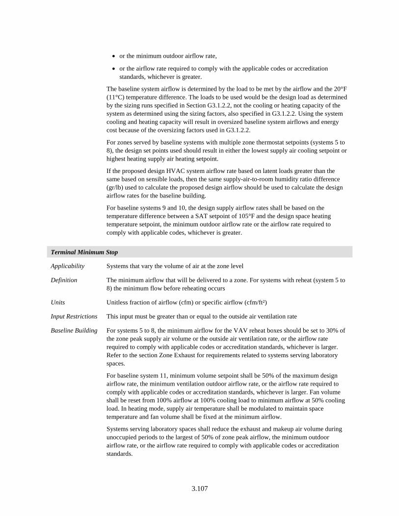
3.107
• or the minimum outdoor airflow rate,
• or the airflow rate required to comply with the applicable codes or accreditation standards, whichever is greater.
The baseline system airflow is determined by the load to be met by the airflow and the 20°F (11°C) temperature difference. The loads to be used would be the design load as determined by the sizing runs specified in Section G3.1.2.2, not the cooling or heating capacity of the system as determined using the sizing factors, also specified in G3.1.2.2. Using the system cooling and heating capacity will result in oversized baseline system airflows and energy cost because of the oversizing factors used in G3.1.2.2.
For zones served by baseline systems with multiple zone thermostat setpoints (systems 5 to 8), the design set points used should result in either the lowest supply air cooling setpoint or highest heating supply air heating setpoint.
If the proposed design HVAC system airflow rate based on latent loads greater than the same based on sensible loads, then the same supply-air-to-room humidity ratio difference (gr/lb) used to calculate the proposed design airflow should be used to calculate the design airflow rates for the baseline building.
For baseline systems 9 and 10, the design supply airflow rates shall be based on the temperature difference between a SAT setpoint of 105°F and the design space heating temperature setpoint, the minimum outdoor airflow rate or the airflow rate required to comply with applicable codes, whichever is greater.
Terminal Minimum Stop
Applicability Systems that vary the volume of air at the zone level
Definition The minimum airflow that will be delivered to a zone. For systems with reheat (system 5 to 8) the minimum flow before reheating occurs
Units Unitless fraction of airflow (cfm) or specific airflow (cfm/ft²)
Input Restrictions This input must be greater than or equal to the outside air ventilation rate
Baseline Building For systems 5 to 8, the minimum airflow for the VAV reheat boxes should be set to 30% of the zone peak supply air volume or the outside air ventilation rate, or the airflow rate required to comply with applicable codes or accreditation standards, whichever is larger. Refer to the section Zone Exhaust for requirements related to systems serving laboratory spaces.
For baseline system 11, minimum volume setpoint shall be 50% of the maximum design airflow rate, the minimum ventilation outdoor airflow rate, or the airflow rate required to comply with applicable codes or accreditation standards, whichever is larger. Fan volume shall be reset from 100% airflow at 100% cooling load to minimum airflow at 50% cooling load. In heating mode, supply air temperature shall be modulated to maintain space temperature and fan volume shall be fixed at the minimum airflow.
Systems serving laboratory spaces shall reduce the exhaust and makeup air volume during unoccupied periods to the largest of 50% of zone peak airflow, the minimum outdoor airflow rate, or the airflow rate required to comply with applicable codes or accreditation standards.
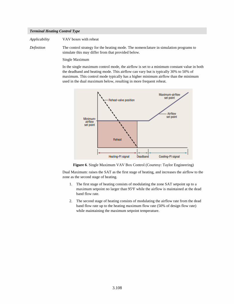
3.108
Terminal Heating Control Type
Applicability VAV boxes with reheat
Definition The control strategy for the heating mode. The nomenclature in simulation programs to simulate this may differ from that provided below.
Single Maximum
In the single maximum control mode, the airflow is set to a minimum constant value in both the deadband and heating mode. This airflow can vary but is typically 30% to 50% of maximum. This control mode typically has a higher minimum airflow than the minimum used in the dual maximum below, resulting in more frequent reheat.
Figure 6. Single Maximum VAV Box Control (Courtesy: Taylor Engineering)
Dual Maximum: raises the SAT as the first stage of heating, and increases the airflow to the zone as the second stage of heating.
1. The first stage of heating consists of modulating the zone SAT setpoint up to a maximum setpoint no larger than 95ºF while the airflow is maintained at the dead band flow rate.
2. The second stage of heating consists of modulating the airflow rate from the dead band flow rate up to the heating maximum flow rate (50% of design flow rate) while maintaining the maximum setpoint temperature.
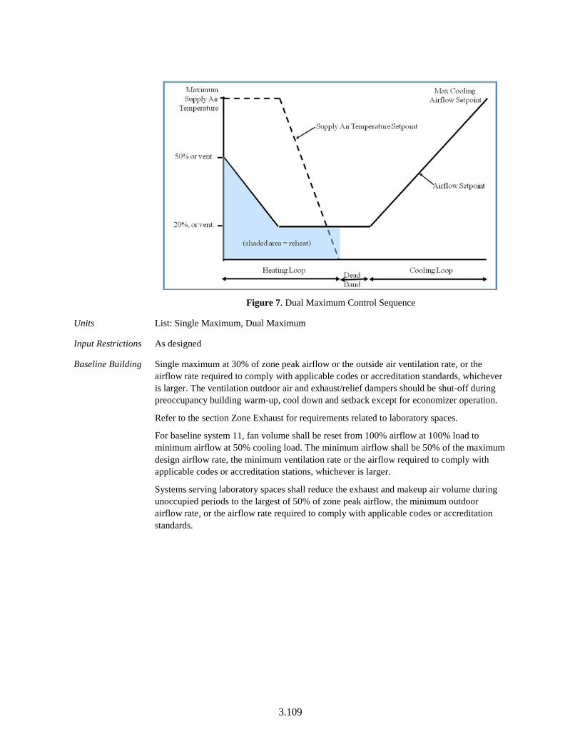
3.109
Figure 7. Dual Maximum Control Sequence
Units List: Single Maximum, Dual Maximum
Input Restrictions As designed
Baseline Building Single maximum at 30% of zone peak airflow or the outside air ventilation rate, or the airflow rate required to comply with applicable codes or accreditation standards, whichever is larger. The ventilation outdoor air and exhaust/relief dampers should be shut-off during preoccupancy building warm-up, cool down and setback except for economizer operation.
Refer to the section Zone Exhaust for requirements related to laboratory spaces.
For baseline system 11, fan volume shall be reset from 100% airflow at 100% load to minimum airflow at 50% cooling load. The minimum airflow shall be 50% of the maximum design airflow rate, the minimum ventilation rate or the airflow required to comply with applicable codes or accreditation stations, whichever is larger.
Systems serving laboratory spaces shall reduce the exhaust and makeup air volume during unoccupied periods to the largest of 50% of zone peak airflow, the minimum outdoor airflow rate, or the airflow rate required to comply with applicable codes or accreditation standards.
3.110
3.5.5.2 Overhead Fan-Powered Boxes
This group of building descriptors applies to terminal equipment that includes zone fans for overhead VAV systems. The building descriptors are applicable for baseline building systems 6 and 8. When parallel fan powered boxes are required for the baseline building, terminal fans shall run as the first stage of heating before the reheat coil is energized. Fans in parallel VAV fan-powered boxes shall be sized for 50% of the peak design primary air (from the VAV air-handling unit) flow rate and shall be modeled with 0.35 W/cfm fan power. Minimum volume setpoints for fan-powered boxes shall be equal to 30% of peak design primary airflow rate or the rate required to meet the minimum outdoor air ventilation requirement, whichever is larger. The supply air temperature setpoint shall be constant at the design condition.
Fan-Powered Box Type
Applicability HVAC zones that have fan-powered boxes
Definition Defines the type of fan-powered induction box. This is either:
• Series, constant volume box fan; or
• Parallel, constant volume box fan
Units List (see above)
Input Restrictions As designed
Baseline Building Applicable to baseline systems 6 and 8 and the fan-powered box type is parallel, with a constant volume fan
Fan Power
Applicability HVAC zones that have fan-powered boxes
Definition The rated power input of the fan in a fan-powered box
Units W or W/cfm
Input Restrictions As designed
Baseline Building For baseline building systems 6 and 8, power is prescribed at 0.35 W/cfm
Parallel Fan-Powered Box-Induced Air Zone
Applicability HVAC zones that have fan-powered boxes
Definition Zone from which a series or parallel fan-powered box draws its air
Units List (of zones)
Input Restrictions As designed
Baseline Building If the proposed design has a plenum, then induced air will be drawn from that plenum. If the proposed design does not have a plenum, then induced air will be drawn from the space.
3.111
Parallel Fan-Powered Box- Induction Ratio
Applicability HVAC zones that have fan-powered boxes
Definition The ratio of induction-side airflow of a fan-powered box at design heating conditions to the design primary airflow
Units Ratio
Input Restrictions As designed
Baseline Building 50%
Parallel Fan Box Thermostat Setpoint
Applicability HVAC zones that have parallel fan-powered boxes
Definition The temperature difference above the heating setpoint at which the parallel fan is turned on
Units Degrees Fahrenheit (°F)
Input Restrictions 2°F above the heating setpoint schedule
Baseline Building 2°F above the heating setpoint schedule
Fan-Powered Boxes: Terminal Heating Control Type
Applicability HVAC zones that have parallel fan-powered boxes
Definition Fan Control: With parallel style fan-powered VAV boxes, the constant volume terminal unit fan is only on when the primary airflow is at design minimum and the zone temperature is less than 2°F above the heating setpoint schedule. When the system is scheduled to operate and the zone terminal fan is running, the box mixes plenum air with primary air.
Heating Operation: During heating mode, the terminal unit discharge air temperature is increased from minimum to the design heating temperature. Throughout occupied heating the cooling, primary airflow is kept at design minimum and the terminal unit fan is running.
Deadband Operation: The cooling primary airflow is kept at minimum airflow and the heating valve is closed. The terminal unit fan will energize as the first stage of heating when the zone temperature drops to 2°F. above heating setpoint.
Cooling Operation: As the space temperature increases, the cooling supply airflow is increased from minimum to design cooling maximum. Throughout cooling the box fan is off. To comply with Standard 90.1-2016 Section 6.5.2.1, Exception (1), the minimum primary airflow for this control logic must be no larger than 30% of the zone design cooling airflow or the minimum airflow for ventilation.
Night Cycle Heating Control: A call for heating during night cycle control shall be met by running the terminal fan and increasing the terminal unit discharge air temperature from minimum to the design heating temperature without the use of primary air.
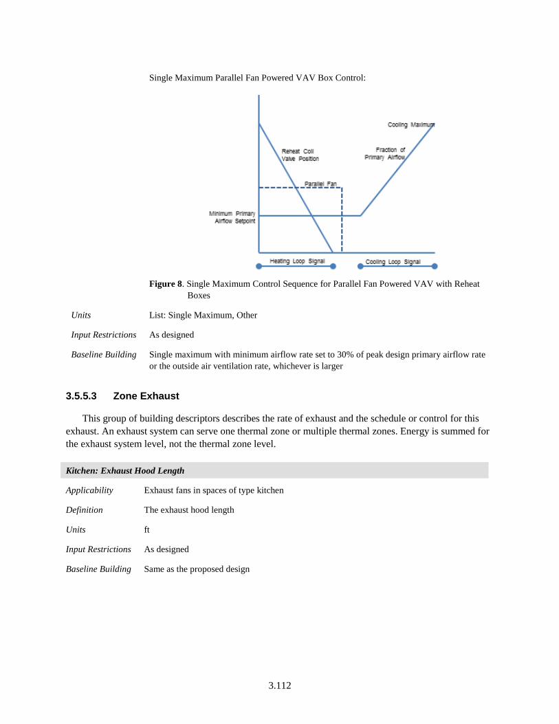
3.112
Single Maximum Parallel Fan Powered VAV Box Control:
Figure 8. Single Maximum Control Sequence for Parallel Fan Powered VAV with Reheat
Boxes
Units List: Single Maximum, Other
Input Restrictions As designed
Baseline Building Single maximum with minimum airflow rate set to 30% of peak design primary airflow rate or the outside air ventilation rate, whichever is larger
3.5.5.3 Zone Exhaust
This group of building descriptors describes the rate of exhaust and the schedule or control for this exhaust. An exhaust system can serve one thermal zone or multiple thermal zones. Energy is summed for the exhaust system level, not the thermal zone level. Kitchen: Exhaust Hood Length
Applicability Exhaust fans in spaces of type kitchen
Definition The exhaust hood length
Units ft
Input Restrictions As designed
Baseline Building Same as the proposed design
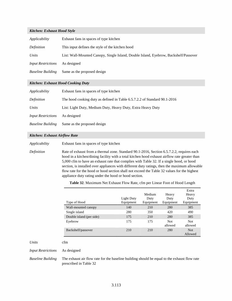
3.113
Kitchen: Exhaust Hood Style
Applicability Exhaust fans in spaces of type kitchen
Definition This input defines the style of the kitchen hood
Units List: Wall-Mounted Canopy, Single Island, Double Island, Eyebrow, Backshelf/Passover
Input Restrictions As designed
Baseline Building Same as the proposed design
Kitchen: Exhaust Hood Cooking Duty
Applicability Exhaust fans in spaces of type kitchen
Definition The hood cooking duty as defined in Table 6.5.7.2.2 of Standard 90.1-2016
Units List: Light Duty, Medium Duty, Heavy Duty, Extra Heavy Duty
Input Restrictions As designed
Baseline Building Same as the proposed design
Kitchen: Exhaust Airflow Rate
Applicability Exhaust fans in spaces of type kitchen
Definition Rate of exhaust from a thermal zone. Standard 90.1-2016, Section 6.5.7.2.2, requires each hood in a kitchen/dining facility with a total kitchen hood exhaust airflow rate greater than 5,000 cfm to have an exhaust rate that complies with Table 32. If a single hood, or hood section, is installed over appliances with different duty ratings, then the maximum allowable flow rate for the hood or hood section shall not exceed the Table 32 values for the highest appliance duty rating under the hood or hood section.
Table 32. Maximum Net Exhaust Flow Rate, cfm per Linear Foot of Hood Length
Type of Hood Light Duty Equipment
Medium Duty
Equipment
Heavy Duty
Equipment
Extra Heavy Duty
Equipment Wall-mounted canopy 140 210 280 385 Single island 280 350 420 490 Double island (per side) 175 210 280 385 Eyebrow 175 175 Not
allowed Not
allowed Backshelf/passover 210 210 280 Not
Allowed
Units cfm
Input Restrictions As designed
Baseline Building The exhaust air flow rate for the baseline building should be equal to the exhaust flow rate prescribed in Table 32
3.114
Kitchen: Demand Ventilation
Applicability All kitchen HVAC zones
Definition A demand ventilation system uses a light beam and a photo detector to detect the presence of smoke. It also has a temperature sensor to detect heat. The exhaust fan slows down below design levels and both exhaust and replacement airflow rates are reduced when the system detects no smoke or heat.
Units Unitless
Input Restrictions As designed. Exhaust fans controlled with a demand ventilation system with a minimum flow no more than 50% shall be modeled as running at 75% during all exhaust fan operating hours.
Baseline Building Same as proposed except fan speed would not be reduced due to demand ventilation systems
Laboratory: Exhaust Minimum Airflow Rate
Applicability All laboratory zones
Definition Rate of exhaust from a zone
Units cfm
Input Restrictions As designed
Baseline Building Same as proposed except for the unoccupied periods, where systems serving laboratory spaces shall reduce the exhaust and makeup air volume during unoccupied periods to the largest of 50% of zone peak airflow, the minimum outdoor airflow rate, or the airflow rate required to comply with applicable codes or accreditation standards.
Baseline systems serving only laboratory spaces that are prohibited from recirculating return air by code or accretion standard, the baseline system shall be modeled with 100% outdoor air.
Exhaust Fan Name
Applicability All HVAC zones
Definition A reference to an exhaust fan system that serves the thermal zone
Units Text or other unique reference to an exhaust fan system defined in the secondary systems section
Input Restrictions As designed
Baseline Building Same as the proposed design
3.115
Exhaust Fan Operation Schedule
Applicability All HVAC zones
Definition Schedule indicating the pattern of use for exhaust air from the thermal zone. For laboratory exhaust hoods, this input should consider the position of fume hood sash opening. For toilets and other exhaust applications, the schedule may coincide with the operation of the exhaust fan system.
Units Data structure: schedule, fraction
Input Restrictions As designed
Baseline Building Same as proposed except for the unoccupied periods, where systems serving laboratory spaces shall reduce the exhaust and makeup air volume during unoccupied periods to the largest of 50% of zone peak airflow, the minimum outdoor airflow rate, or the airflow rate required to comply with applicable codes or accreditation standards
3.5.5.4 Outdoor Air Ventilation
Outdoor Air Ventilation Source
Applicability All HVAC zones
Definition The source of outdoor air ventilation for an HVAC system. The choices are:
• Natural (by operable openings)
• Mechanical (by fan)
Units List: Natural or mechanical
Input Restrictions As designed
Baseline Building Ventilation is set to mechanical for the baseline building
Minimum Outdoor Air Ventilation Rate
Applicability All HVAC zones
Definition The minimum quantity of outdoor ventilation air that must be provided to the space when it is occupied
Units cfm or cfm/ft²
Input Restrictions As designed
Baseline Building Minimum ventilation system outdoor air intake flow shall be the same for the proposed and baseline building designs. Except in the following conditions:
• Demand control ventilation shall not be modeled in zones served by systems with outdoor air less than 3000 cfm and occupant density of 100 people per 1000 ft2 or less.
• If the minimum outdoor air intake flow in the proposed design is provided in excess of the amount required by the rating authority or building official, then the baseline building design shall be modeled to reflect the greater of that required by the rating
3.116
authority or building official and will be less than the proposed design.
• For systems serving kitchens, the minimum outside air ventilation rate is the exhaust air ventilation rate minus available transfer air. Refer to building descriptor Kitchen Exhaust.
• For systems serving laboratories, refer to building descriptor Laboratory Exhaust, Section 3.5.5.3.
• When designing systems in accordance to Standard 62.1, Section 6.2, “Ventilation Rate Procedure”. Refer to Section 3.5.5.5 of this document for requirements.
Design Outdoor Air Ventilation Rate and Schedule
Applicability All HVAC zones
Definition The quantity of outdoor air ventilation that is provided to the space for the specified thermal zone at maximum occupancy
Units cfm or cfm/occupant
Input Restrictions The outdoor air ventilation rate would be as designed.
Outdoor air ventilation schedule for proposed building can be either of the two:
a. As designed
b. The outdoor air ventilation schedule follows the HVAC availability schedule. In this case outdoor air isn’t supplied during unoccupied times or during night cycling operation.
Some proposed building designs might bring in ventilation air during unoccupied hours for night flush or economizer operation. Due to these reasons, an option for user input of schedule for outdoor air availability is provided.
Baseline Building Same as proposed, except:
• When designing systems in accordance with ASHRAE Standard 62.1, Section 6.2, Ventilation Rate Procedure, where the proposed design has a zone air distribution effectiveness greater than 1.0, the baseline ventilation shall be calculated using the proposed design ventilation rate procedure calculation with the zone air distribution effectiveness changed to 1.0. Refer to Section 3.5.5.5 for details on the ventilation rate procedure.
• If the proposed design ventilation rate exceeds that required by the rating authority or building official, then the baseline design ventilation rate shall be only what is required by the rating authority or building official, whichever is greater.
3.117
Ventilation Control Method
Applicability All HVAC zones
Definition The method used to determine outside air ventilation needed for each hour in the simulation. This information is reported to the system serving the zone. The method of controlling outside air at the system level in response to this information is discussed under secondary systems. Options at the zone level are:
• Occupant sensors: When the space is occupied, the outside air requirement is equal to the design ventilation rate; otherwise, the outside air requirement is the minimum ventilation rate.
• CO2 sensors in the space: The outside air is varied to maintain a maximum CO2 concentration in the space. This shall be approximated by multiplying the ventilation rate per occupant by the number of occupants for that hour. (When turnstile counts are used to automatically adjust ventilation levels based on occupancy, this method may also be used.)
• Fixed ventilation rate: Outside air is delivered to the zone at a constant rate and is equal to the design ventilation rate (see above).
Units List (see above)
Input Restrictions As designed
Baseline Building Baseline building shall be modeled with a fixed ventilation rate which would be equal to the design ventilation rate (see above). No ventilation control methods shall be modeled for the baseline building design except for the following:
• Demand control ventilation shall be modeled in zones served by systems with outdoor air greater than or equal to 3000 cfm and occupant density of 100 people per 1000 ft2 or less.
Design Ventilation Rate: Demand Control Ventilation
Applicability All HVAC zones
Definition Demand control ventilation is required for spaces larger than 500 ft2 and with a design occupancy for ventilation of greater than or equal to 25 people per 1000 ft2 of floor area and served by systems with one or more of the following:
a. An air-side economizer
b. Automatic modulating control of the outdoor air damper
c. A design outdoor airflow greater than 3000 cfm
Exceptions:
a. Systems with the exhaust air energy recovery complying with Standard 90.1-2016, Section 6.5.6.1
b. Multiple-zone systems without dynamic demand control (DDC) of individual zones communicating with a central control panel
c. Systems with a design outdoor airflow less than 750 cfm
g. Spaces where >75% of the space design outdoor airflow is required for makeup air
3.118
that is exhausted from the space or transfer air that is required for makeup air that is exhausted from other spaces.
h. Spaces with one of the following occupancy categories as defined in ASHRAE Standard 62.1: correctional cells, daycare sickrooms, science labs, barbers, beauty and nail salons, and bowling alley seating.
Units cfm or cfm/occupant
Input Restrictions As designed. DCV is a mandatory requirement for spaces larger than 500 ft2, with design occupancy of more than 25 people per 1000 ft2 unless any of the exceptions specified above apply.
Baseline Building DCV is not modeled for the baseline building except for zones served by systems with outdoor air greater than or equal to 3000 cfm and occupant density of 100 people per 1000 ft2 or less
3.5.5.5 Ventilation Rate Procedure
Ventilation Standard
Applicability All projects
Definition The ventilation standard used for the calculation of minimum ventilation rate required. The ventilation rates are defined based on the ventilation standard selected. This should be specified at the project level.
Units List. ASHRAE Standard 62.1, IMC-2012, Title-24-2013, ASHRAE 170, Other
Input Restrictions No restrictions. Any of the defined standards can be selected.
Baseline Building Same as proposed
The baseline rules for determining the use of DCV are defined according to Standard 90.1-2016, for any specified standard, including ‘Other’.
Ventilation Specification Method
Applicability All HVAC zones
Definition The method used to calculate total ventilation rates to a zone. The input must be either “Sum,” “Maximum,” or “No Ventilation.”
• Sum means that the flows calculated from the fields Outdoor Airflow per Person and Outdoor Airflow per Area will be added to obtain the zone outdoor airflow rate.
• Maximum means that the maximum flow derived from Outdoor Airflow per Person, Outdoor Airflow per Area, and Air Changes per Hour (using the associated conversions to cfm for each field) will be used as the zone outdoor airflow rate.
• No ventilation indicates that the zone doesn’t receive any outdoor air.
Units List: Sum, Maximum, No Ventilation
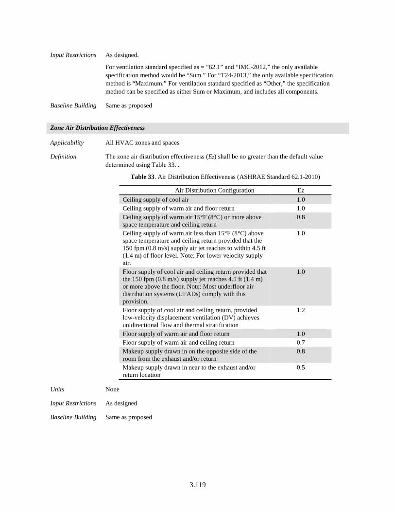
3.119
Input Restrictions As designed.
For ventilation standard specified as = “62.1” and “IMC-2012,” the only available specification method would be “Sum.” For “T24-2013,” the only available specification method is “Maximum.” For ventilation standard specified as “Other,” the specification method can be specified as either Sum or Maximum, and includes all components.
Baseline Building Same as proposed
Zone Air Distribution Effectiveness
Applicability All HVAC zones and spaces
Definition The zone air distribution effectiveness (Ez) shall be no greater than the default value determined using Table 33. .
Table 33. Air Distribution Effectiveness (ASHRAE Standard 62.1-2010)
Air Distribution Configuration Ez Ceiling supply of cool air 1.0 Ceiling supply of warm air and floor return 1.0 Ceiling supply of warm air 15°F (8°C) or more above space temperature and ceiling return
0.8
Ceiling supply of warm air less than 15°F (8°C) above space temperature and ceiling return provided that the 150 fpm (0.8 m/s) supply air jet reaches to within 4.5 ft (1.4 m) of floor level. Note: For lower velocity supply air.
1.0
Floor supply of cool air and ceiling return provided that the 150 fpm (0.8 m/s) supply jet reaches 4.5 ft (1.4 m) or more above the floor. Note: Most underfloor air distribution systems (UFADs) comply with this provision.
1.0
Floor supply of cool air and ceiling return, provided low-velocity displacement ventilation (DV) achieves unidirectional flow and thermal stratification
1.2
Floor supply of warm air and floor return 1.0 Floor supply of warm air and ceiling return 0.7 Makeup supply drawn in on the opposite side of the room from the exhaust and/or return
0.8
Makeup supply drawn in near to the exhaust and/or return location
0.5
Units None
Input Restrictions As designed
Baseline Building Same as proposed
3.120
Ventilation Multiplier
Applicability All projects
Definition The ventilation multiplier is defined at the project level. This multiplier is applied to the user’s design component ventilation rates (Ra and Rp) to uniformly increase the component ventilation rates entered. The principal purpose of the multiplier is to facilitate simulating a uniform increase in proposed design ventilation rates, such as for buildings pursuing the LEED credit for 30% increased ventilation.
Units No units
Input Restrictions As designed. The default value is 1.
Baseline Building The ventilation multiplier is always 1 for the baseline building
Ventilation Rates
Applicability All HVAC zones
Definition The method used to calculate total ventilation rates to a zone. The input must be either flow/person, flow/area, flow/zone, air changes/hour, sum, or maximum.
• Flow/Person (Rp) means the program will use the input from the field Outdoor Airflow per Person and the actual zone occupancy to calculate a zone outdoor airflow rate.
• Flow/Area (Ra) means that the program will use the input from the field Outdoor Airflow per Zone Floor Area and the actual zone floor area as the zone outdoor airflow rate. Flow/Zone means that the program will use the input of the field Outdoor Airflow per Zone as the zone outdoor airflow rate.
• Air changes per hour (ACH) means that the program will use the input from the field Air Changes per Hour and the actual zone volume (divided by 3600 seconds per hour) as the zone outdoor airflow rate.
• For non-occupied spaces, the values for Ra, Rp and ACH can be zero for the proposed and baseline building. Software tools can allow a check-box for indicating spaces that would be non-occupied and hence are permitted to have a value for zero for Ra and Rp.
Units List: Flow/Person, Flow/Area, Air Changes per Hour
Input Restrictions As designed. If the user specifies ventilation standard as ‘Other’ and DCV is used, a non-zero value for Rp must be specified for the ventilation air flow to vary with occupancy.
Baseline Building The ventilation rates for the baseline building are determined by the ventilation standard and the space function. The code minimum ventilation rates cannot be overridden by the user.
For zones/spaces with ventilation standard specified as ‘Other’
• The code minimum ventilation rates are required to be specified by the user.
• If DCV controls are not specified for the proposed but are required for the baseline, the ventilation rate for the area component is determined based on Standard 62.1 and the balance of the user’s total design air flow is allocated to the Rp component for the baseline.
3.121
Total Design Zone Ventilation Airflow
Applicability All HVAC zones
Definition The total design outdoor air supplied to a zone (Vz-design).
Minimum outdoor air supplied to a zone (Vbz-min) is calculated based on the user input values of the ventilation multiplier (Vm), Ez, Ra and Rp. The method used to calculate total minimum ventilation airflow to a zone is specified below-
𝑉𝑉𝑏𝑏𝑏𝑏−𝑚𝑚𝑚𝑚𝑚𝑚 = 𝑉𝑉𝑚𝑚 × [(𝑅𝑅𝑝𝑝 × 𝐵𝐵𝑏𝑏 + 𝑅𝑅𝑌𝑌 × 𝐴𝐴𝑏𝑏)/𝐸𝐸𝑏𝑏] (9)
Where,
Vbz-min = Total Breathing Zone Outdoor Airflow (CFM)
Vm = Ventilation Multiplier
Rp = Outdoor Airflow Rate per Person (CFM/person)
Ra = Outdoor Airflow Rate per unit Area (CFM/ft2)
Pz = Zone Population: The number of people in the zone during typical occupancy
Az = Zone Floor Area (ft2): the net occupiable floor area of the zone.
Units List: CFM
Input Restrictions As designed. The total design ventilation airflows should also include the impact of Ez and the ventilation multiplier. The user entered value for space/zone design ventilation airflow is required to be within 3% of the value calculated from the user entered Ra, Rp, Ez and Vm values, else the compliance analysis shouldn’t be allowed to proceed. The user is required to modify the values for Ra, Rp or Ez such that the total airflow calculated from the components and the user defined airflow is within the tolerance limit. Similarly, if DCV controls are used in the proposed building design, the user entered value for Vz-design should be within 3% tolerance of the value calculated by the design area rate component (Ra) and Ez.
Exhaust airflows are checked at the building story level. If the sum of proposed total design ventilation airflows for all spaces on a building story level (excluding spaces with ventilation standard specified as ‘Other’) is not within 10% of the calculated total code minimum ventilation airflow, compliance analysis should not be allowed to proceed. To proceed, either the ventilation airflows for spaces that are under-ventilated, need to be increased or alternatively, the ventilation standard should be specified as ‘Other’ for spaces that are under-ventilated. For zones/spaces with DCV controls, the minimum ventilation airflow is the airflow when the space is unoccupied, calculated using the area component and Ez.
Baseline Building The baseline design ventilation airflow rates for all spaces/thermal zones equal the proposed with the exception of the following:
a. The zone distribution effectiveness for the proposed building (Ez) > 1. In this case, Ez = 1 for the baseline building.
b. The proposed design ventilation airflow, on a building story basis, exceeds the code minimum ventilation airflow for the building story. In this case, the baseline ventilation rates will be calculated by uniformly reducing the proposed rates such that the total ventilation airflow to spaces on the building story equals the code
3.122
minimum flow. This maintains a proportional distribution of ventilation air to spaces/zones on the building story between the proposed and baseline designs. Spaces with ventilation standard specified as “Other” are excluded from adjustments, and the baseline design ventilation rate equals the proposed.
c. The proposed design ventilation multiplier is greater than 1. In this case, the baseline design ventilation airflow is not increased by the multiplier. Instead, the total baseline design ventilation airflow is adjusted, as described in exception b, to be equal to the code minimum ventilation airflow.
d. The total proposed design ventilation airflow (excluding spaces with ventilation standard specified as “Other”), on a building story basis, is greater than 110% of the total building story exhaust airflow. In this case, the baseline design ventilation airflows will be calculated by uniformly reducing the proposed inputs (excluding spaces with ventilation standard specified as “Other”) such that the total ventilation airflow on the building story equals 110% of the total building story exhaust airflow. This maintains a proportional distribution of ventilation air (at design conditions) to spaces on the building story, while allowing sufficient additional ventilation air for pressurization.
Total System Design Ventilation Airflow
Applicability All HVAC systems.
Definition The design outdoor air intake at the system level (Vs-design)
Units CFM
Input Restrictions As designed
Software tools are required to verify the input value for Vs-design. For all the zones served by the system, software tools are required to sum the zone level ventilation (Vbz-min) to calculate the minimum ventilation at the system level (Vs-min). If the design outdoor air intake (Vs-
design) is less than the minimum ventilation airflow (Vs-min), the input should be flagged and the user should be required to increase the value for Vs-design until it is equal to or greater than
Vs-min.
Baseline Building The total system ventilation airflow for the baseline building is the sum of the zone level ventilation for the baseline building
3.123
System Ventilation Efficiency
Applicability All HVAC systems
Definition The efficiency of the ventilation system (Ev). This is the ratio of the design ventilation airflow to the minimum system ventilation airflow.
Ev = Vs-min / Vs-design (10)
Units Ratio (unitless)
Input Restrictions Calculated by software tool
Software tools are required to calculate and verify the input value for Ev. The maximum value of Ev=1 (for single zone systems). If Ev is greater than 1, an error should be displayed to the user and the user is required to increase the value of Vs-design until the value of Ev is less than or equal to 1.
Baseline Building Same as proposed for all zones served by the proposed system. In the scenario where the building has a multizone system in the proposed case, but single zone system in the baseline case, all the zones served by the Multizone system in the proposed case have Ev same as the proposed system.
Similarly, if the proposed system is single zone and the baseline building has multizone systems, then the corresponding zones would have Ev specified as 1, same as the proposed building.
This approach ensures that the ventilation rates are the same between the baseline and the proposed building.
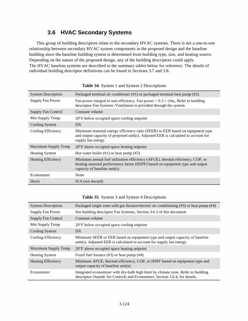
3.124
3.6 HVAC Secondary Systems
This group of building descriptors relate to the secondary HVAC systems. There is not a one-to-one relationship between secondary HVAC system components in the proposed design and the baseline building since the baseline building system is determined from building type, size, and heating source. Depending on the nature of the proposed design, any of the building descriptors could apply. The HVAC baseline systems are described in the summary tables below for reference. The details of individual building descriptor definitions can be found in Sections 3.7 and 3.8.
Table 34. System 1 and System 2 Descriptions
System Description Packaged terminal air conditioner (#1) or packaged terminal heat pump (#2) Supply Fan Power Fan power integral to unit efficiency. Fan power = 0.3 × cfms. Refer to building
descriptor Fan Systems. Ventilation is provided through the system. Supply Fan Control Constant volume Min Supply Temp 20°F below occupied space cooling setpoint Cooling System DX Cooling Efficiency Minimum seasonal energy efficiency ratio (SEER) or EER based on equipment type
and output capacity of proposed unit(s). Adjusted EER is calculated to account for supply fan energy.
Maximum Supply Temp 20°F above occupied space heating setpoint Heating System Hot water boiler (#1) or heat pump (#2) Heating Efficiency Minimum annual fuel utilization efficiency (AFUE), thermal efficiency, COP, or
heating seasonal performance factor (HSPF) based on equipment type and output capacity of baseline unit(s)
Economizer None Ducts N/A (not ducted)
Table 35. System 3 and System 4 Descriptions
System Description Packaged single zone with gas furnace/electric air conditioning (#3) or heat pump (#4) Supply Fan Power See building descriptor Fan Systems, Section 3.6.3 of this document Supply Fan Control Constant volume Min Supply Temp 20°F below occupied space cooling setpoint Cooling System DX Cooling Efficiency Minimum SEER or EER based on equipment type and output capacity of baseline
unit(s). Adjusted EER is calculated to account for supply fan energy. Maximum Supply Temp 20°F above occupied space heating setpoint Heating System Fossil fuel furnace (#3) or heat pump (#4) Heating Efficiency Minimum AFUE, thermal efficiency, COP, or HSPF based on equipment type and
output capacity of baseline unit(s) Economizer Integrated economizer with dry-bulb high limit by climate zone. Refer to building
descriptor Outside Air Controls and Economizer, Section 3.6.4, for details.
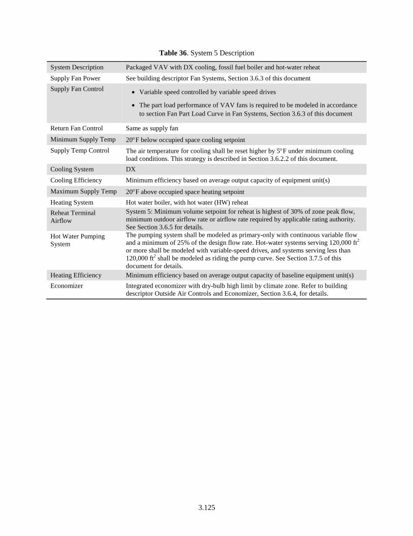
3.125
Table 36. System 5 Description
System Description Packaged VAV with DX cooling, fossil fuel boiler and hot-water reheat Supply Fan Power See building descriptor Fan Systems, Section 3.6.3 of this document Supply Fan Control • Variable speed controlled by variable speed drives
• The part load performance of VAV fans is required to be modeled in accordance to section Fan Part Load Curve in Fan Systems, Section 3.6.3 of this document
Return Fan Control Same as supply fan
Minimum Supply Temp 20°F below occupied space cooling setpoint Supply Temp Control The air temperature for cooling shall be reset higher by 5°F under minimum cooling
load conditions. This strategy is described in Section 3.6.2.2 of this document. Cooling System DX Cooling Efficiency Minimum efficiency based on average output capacity of equipment unit(s)
Maximum Supply Temp 20°F above occupied space heating setpoint Heating System Hot water boiler, with hot water (HW) reheat Reheat Terminal Airflow
System 5: Minimum volume setpoint for reheat is highest of 30% of zone peak flow, minimum outdoor airflow rate or airflow rate required by applicable rating authority. See Section 3.6.5 for details.
Hot Water Pumping System
The pumping system shall be modeled as primary-only with continuous variable flow and a minimum of 25% of the design flow rate. Hot-water systems serving 120,000 ft2 or more shall be modeled with variable-speed drives, and systems serving less than 120,000 ft2 shall be modeled as riding the pump curve. See Section 3.7.5 of this document for details.
Heating Efficiency Minimum efficiency based on average output capacity of baseline equipment unit(s) Economizer Integrated economizer with dry-bulb high limit by climate zone. Refer to building
descriptor Outside Air Controls and Economizer, Section 3.6.4, for details.
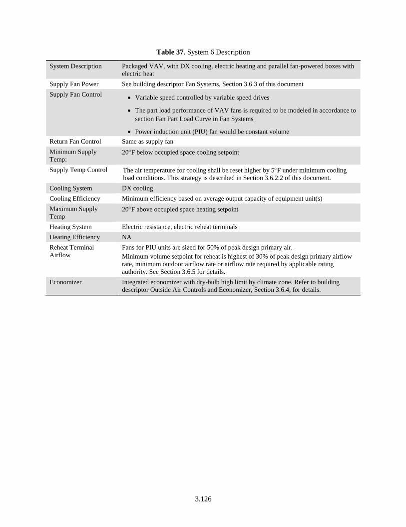
3.126
Table 37. System 6 Description
System Description Packaged VAV, with DX cooling, electric heating and parallel fan-powered boxes with electric heat
Supply Fan Power See building descriptor Fan Systems, Section 3.6.3 of this document Supply Fan Control • Variable speed controlled by variable speed drives
• The part load performance of VAV fans is required to be modeled in accordance to section Fan Part Load Curve in Fan Systems
• Power induction unit (PIU) fan would be constant volume Return Fan Control Same as supply fan Minimum Supply Temp:
20°F below occupied space cooling setpoint
Supply Temp Control The air temperature for cooling shall be reset higher by 5°F under minimum cooling load conditions. This strategy is described in Section 3.6.2.2 of this document.
Cooling System DX cooling Cooling Efficiency Minimum efficiency based on average output capacity of equipment unit(s) Maximum Supply Temp
20°F above occupied space heating setpoint
Heating System Electric resistance, electric reheat terminals Heating Efficiency NA Reheat Terminal Airflow
Fans for PIU units are sized for 50% of peak design primary air. Minimum volume setpoint for reheat is highest of 30% of peak design primary airflow rate, minimum outdoor airflow rate or airflow rate required by applicable rating authority. See Section 3.6.5 for details.
Economizer Integrated economizer with dry-bulb high limit by climate zone. Refer to building descriptor Outside Air Controls and Economizer, Section 3.6.4, for details.
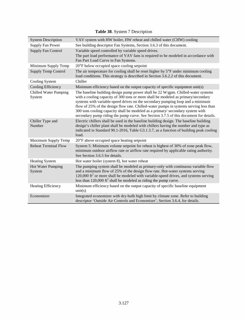
3.127
Table 38. System 7 Description
System Description VAV system with HW boiler, HW reheat and chilled water (CHW) cooling Supply Fan Power See building descriptor Fan Systems, Section 3.6.3 of this document. Supply Fan Control Variable speed controlled by variable speed drives.
The part load performance of VAV fans is required to be modeled in accordance with Fan Part Load Curve in Fan Systems.
Minimum Supply Temp 20°F below occupied space cooling setpoint Supply Temp Control The air temperature for cooling shall be reset higher by 5°F under minimum cooling
load conditions. This strategy is described in Section 3.6.2.2 of this document. Cooling System Chiller Cooling Efficiency Minimum efficiency based on the output capacity of specific equipment unit(s) Chilled Water Pumping System
The baseline building design pump power shall be 22 W/gpm. Chilled-water systems with a cooling capacity of 300 tons or more shall be modeled as primary/secondary systems with variable-speed drives on the secondary pumping loop and a minimum flow of 25% of the design flow rate. Chilled-water pumps in systems serving less than 300 tons cooling capacity shall be modeled as a primary/ secondary system with secondary pump riding the pump curve. See Section 3.7.5 of this document for details.
Chiller Type and Number
Electric chillers shall be used in the baseline building design. The baseline building design’s chiller plant shall be modeled with chillers having the number and type as indicated in Standard 90.1-2016, Table G3.1.3.7, as a function of building peak cooling load.
Maximum Supply Temp 20°F above occupied space heating setpoint Reheat Terminal Flow System 5: Minimum volume setpoint for reheat is highest of 30% of zone peak flow,
minimum outdoor airflow rate or airflow rate required by applicable rating authority. See Section 3.6.5 for details.
Heating System Hot water boiler (system 8), hot water reheat Hot Water Pumping System
The pumping system shall be modeled as primary-only with continuous variable flow and a minimum flow of 25% of the design flow rate. Hot-water systems serving 120,000 ft2 or more shall be modeled with variable-speed drives, and systems serving less than 120,000 ft2 shall be modeled as riding the pump curve.
Heating Efficiency Minimum efficiency based on the output capacity of specific baseline equipment unit(s)
Economizer Integrated economizer with dry-bulb high limit by climate zone. Refer to building descriptor ‘Outside Air Controls and Economizer’, Section 3.6.4, for details.
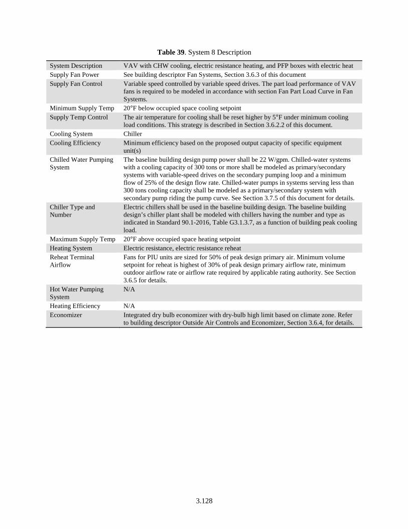
3.128
Table 39. System 8 Description
System Description VAV with CHW cooling, electric resistance heating, and PFP boxes with electric heat Supply Fan Power See building descriptor Fan Systems, Section 3.6.3 of this document Supply Fan Control Variable speed controlled by variable speed drives. The part load performance of VAV
fans is required to be modeled in accordance with section Fan Part Load Curve in Fan Systems.
Minimum Supply Temp 20°F below occupied space cooling setpoint Supply Temp Control The air temperature for cooling shall be reset higher by 5°F under minimum cooling
load conditions. This strategy is described in Section 3.6.2.2 of this document. Cooling System Chiller Cooling Efficiency Minimum efficiency based on the proposed output capacity of specific equipment
unit(s) Chilled Water Pumping System
The baseline building design pump power shall be 22 W/gpm. Chilled-water systems with a cooling capacity of 300 tons or more shall be modeled as primary/secondary systems with variable-speed drives on the secondary pumping loop and a minimum flow of 25% of the design flow rate. Chilled-water pumps in systems serving less than 300 tons cooling capacity shall be modeled as a primary/secondary system with secondary pump riding the pump curve. See Section 3.7.5 of this document for details.
Chiller Type and Number
Electric chillers shall be used in the baseline building design. The baseline building design’s chiller plant shall be modeled with chillers having the number and type as indicated in Standard 90.1-2016, Table G3.1.3.7, as a function of building peak cooling load.
Maximum Supply Temp 20°F above occupied space heating setpoint Heating System Electric resistance, electric resistance reheat Reheat Terminal Airflow
Fans for PIU units are sized for 50% of peak design primary air. Minimum volume setpoint for reheat is highest of 30% of peak design primary airflow rate, minimum outdoor airflow rate or airflow rate required by applicable rating authority. See Section 3.6.5 for details.
Hot Water Pumping System
N/A
Heating Efficiency N/A Economizer Integrated dry bulb economizer with dry-bulb high limit based on climate zone. Refer
to building descriptor Outside Air Controls and Economizer, Section 3.6.4, for details.
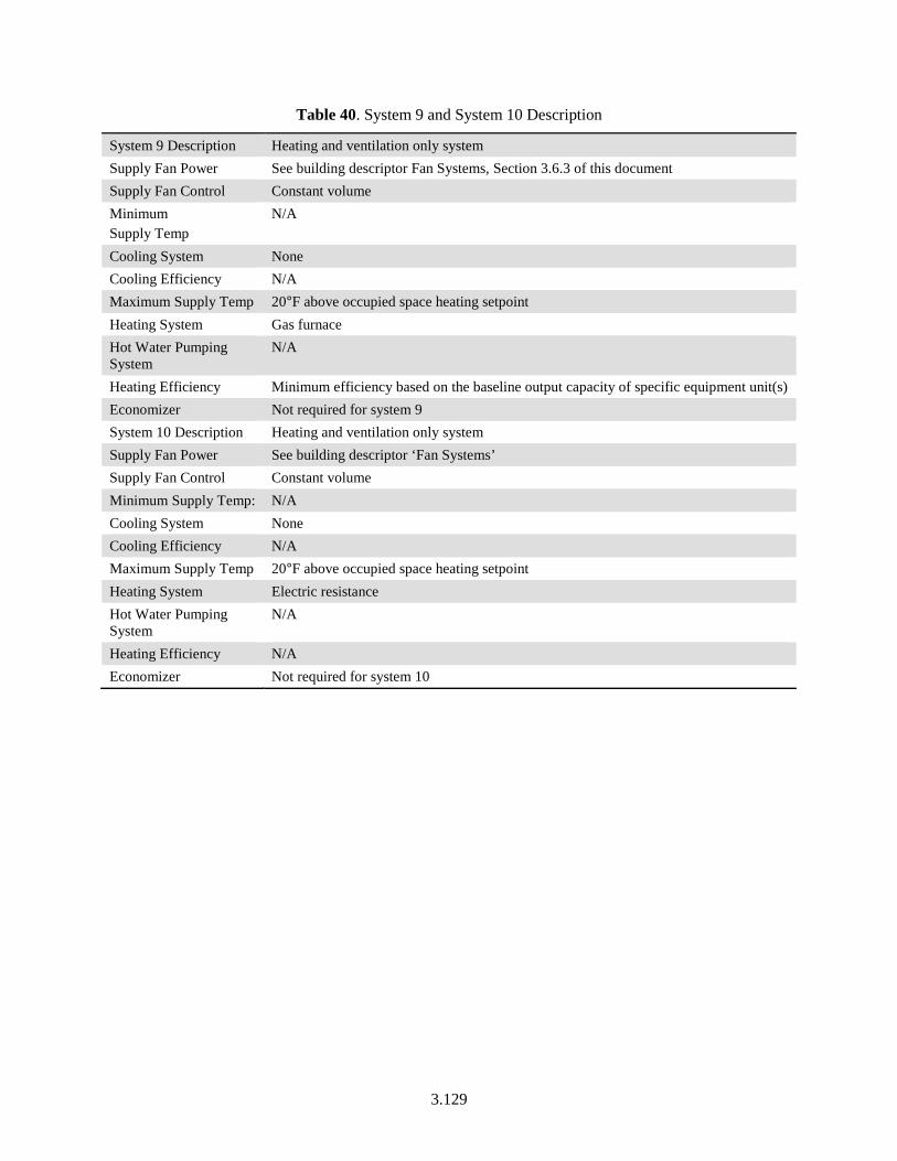
3.129
Table 40. System 9 and System 10 Description
System 9 Description Heating and ventilation only system Supply Fan Power See building descriptor Fan Systems, Section 3.6.3 of this document Supply Fan Control Constant volume Minimum Supply Temp
N/A
Cooling System None Cooling Efficiency N/A Maximum Supply Temp 20°F above occupied space heating setpoint Heating System Gas furnace Hot Water Pumping System
N/A
Heating Efficiency Minimum efficiency based on the baseline output capacity of specific equipment unit(s) Economizer Not required for system 9 System 10 Description Heating and ventilation only system Supply Fan Power See building descriptor ‘Fan Systems’ Supply Fan Control Constant volume Minimum Supply Temp: N/A Cooling System None Cooling Efficiency N/A Maximum Supply Temp 20°F above occupied space heating setpoint Heating System Electric resistance Hot Water Pumping System
N/A
Heating Efficiency N/A Economizer Not required for system 10
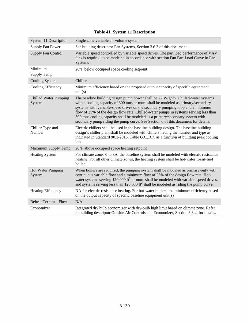
3.130
Table 41. System 11 Description
System 11 Description Single zone variable air volume system Supply Fan Power See building descriptor Fan Systems, Section 3.6.3 of this document Supply Fan Control Variable speed controlled by variable speed drives. The part load performance of VAV
fans is required to be modeled in accordance with section Fan Part Load Curve in Fan Systems
Minimum Supply Temp
20°F below occupied space cooling setpoint
Cooling System Chiller Cooling Efficiency Minimum efficiency based on the proposed output capacity of specific equipment
unit(s) Chilled Water Pumping System
The baseline building design pump power shall be 22 W/gpm. Chilled-water systems with a cooling capacity of 300 tons or more shall be modeled as primary/secondary systems with variable-speed drives on the secondary pumping loop and a minimum flow of 25% of the design flow rate. Chilled-water pumps in systems serving less than 300 tons cooling capacity shall be modeled as a primary/secondary system with secondary pump riding the pump curve. See Section 0 of this document for details.
Chiller Type and Number
Electric chillers shall be used in the baseline building design. The baseline building design’s chiller plant shall be modeled with chillers having the number and type as indicated in Standard 90.1-2016, Table G3.1.3.7, as a function of building peak cooling load.
Maximum Supply Temp 20°F above occupied space heating setpoint Heating System For climate zones 0 to 3A, the baseline system shall be modeled with electric resistance
heating. For all other climate zones, the heating system shall be hot-water fossil-fuel boiler.
Hot Water Pumping System
When boilers are required, the pumping system shall be modeled as primary-only with continuous variable flow and a minimum flow of 25% of the design flow rate. Hot-water systems serving 120,000 ft2 or more shall be modeled with variable-speed drives, and systems serving less than 120,000 ft2 shall be modeled as riding the pump curve.
Heating Efficiency NA for electric resistance heating. For hot-water boilers, the minimum efficiency based on the output capacity of specific baseline equipment unit(s)
Reheat Terminal Flow N/A Economizer Integrated dry bulb economizer with dry-bulb high limit based on climate zone. Refer
to building descriptor Outside Air Controls and Economizer, Section 3.6.4, for details.
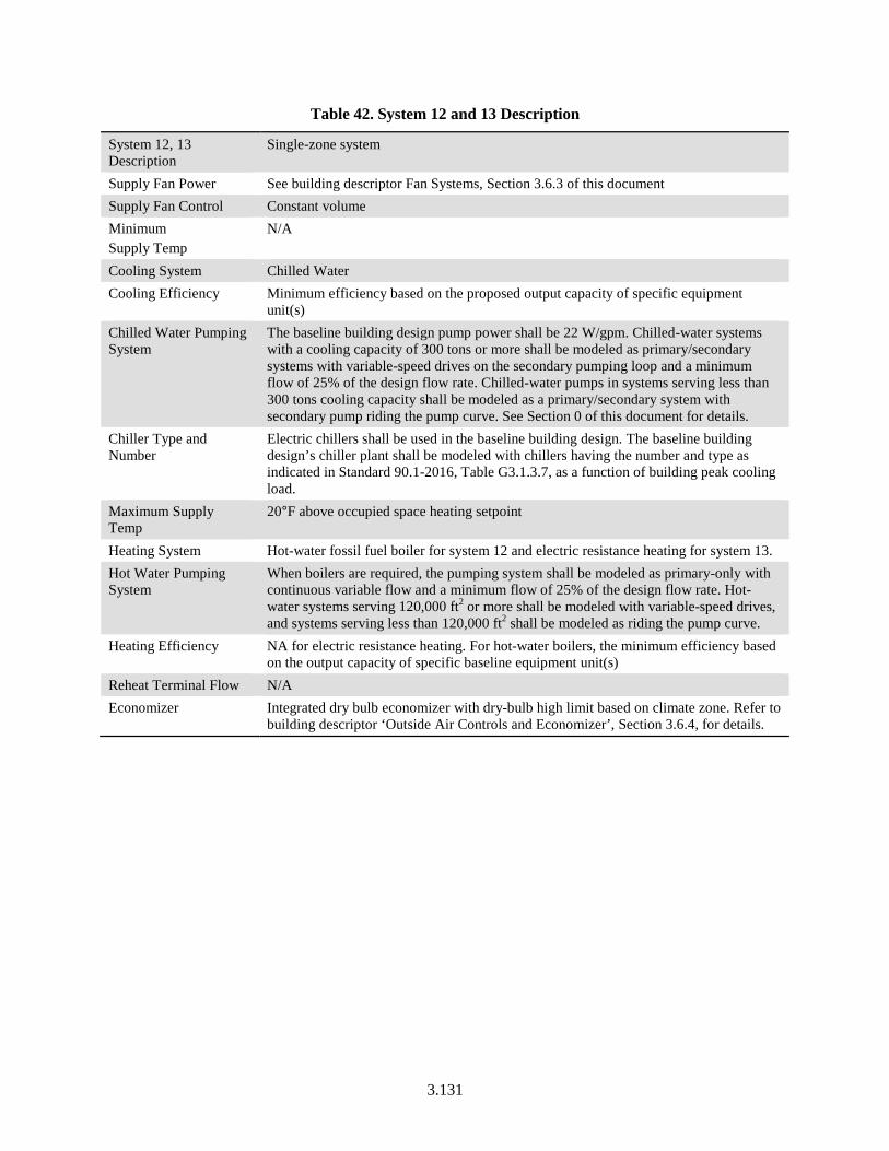
3.131
Table 42. System 12 and 13 Description
System 12, 13 Description
Single-zone system
Supply Fan Power See building descriptor Fan Systems, Section 3.6.3 of this document Supply Fan Control Constant volume Minimum Supply Temp
N/A
Cooling System Chilled Water Cooling Efficiency Minimum efficiency based on the proposed output capacity of specific equipment
unit(s) Chilled Water Pumping System
The baseline building design pump power shall be 22 W/gpm. Chilled-water systems with a cooling capacity of 300 tons or more shall be modeled as primary/secondary systems with variable-speed drives on the secondary pumping loop and a minimum flow of 25% of the design flow rate. Chilled-water pumps in systems serving less than 300 tons cooling capacity shall be modeled as a primary/secondary system with secondary pump riding the pump curve. See Section 0 of this document for details.
Chiller Type and Number
Electric chillers shall be used in the baseline building design. The baseline building design’s chiller plant shall be modeled with chillers having the number and type as indicated in Standard 90.1-2016, Table G3.1.3.7, as a function of building peak cooling load.
Maximum Supply Temp
20°F above occupied space heating setpoint
Heating System Hot-water fossil fuel boiler for system 12 and electric resistance heating for system 13. Hot Water Pumping System
When boilers are required, the pumping system shall be modeled as primary-only with continuous variable flow and a minimum flow of 25% of the design flow rate. Hot-water systems serving 120,000 ft2 or more shall be modeled with variable-speed drives, and systems serving less than 120,000 ft2 shall be modeled as riding the pump curve.
Heating Efficiency NA for electric resistance heating. For hot-water boilers, the minimum efficiency based on the output capacity of specific baseline equipment unit(s)
Reheat Terminal Flow N/A Economizer Integrated dry bulb economizer with dry-bulb high limit based on climate zone. Refer to
building descriptor ‘Outside Air Controls and Economizer’, Section 3.6.4, for details.
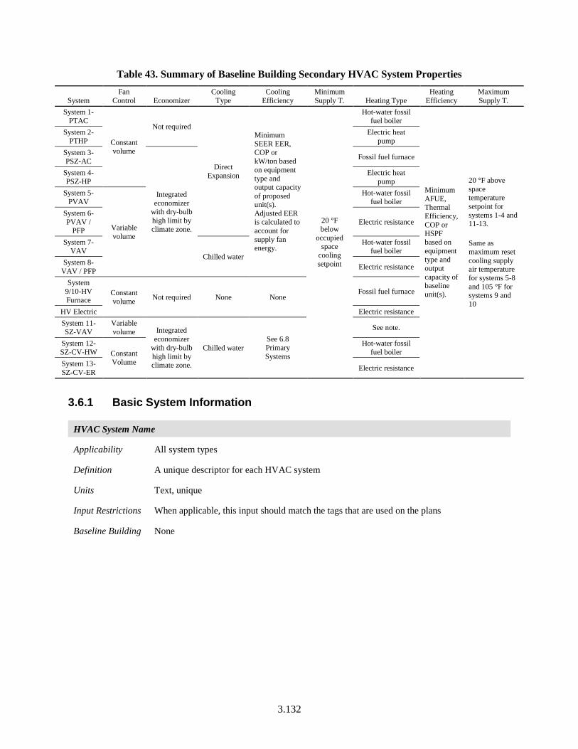
3.132
Table 43. Summary of Baseline Building Secondary HVAC System Properties
System Fan
Control Economizer Cooling
Type Cooling
Efficiency Minimum Supply T. Heating Type
Heating Efficiency
Maximum Supply T.
System 1-PTAC
Constant volume
Not required
Direct Expansion
Minimum SEER EER, COP or kW/ton based on equipment type and output capacity of proposed unit(s). Adjusted EER is calculated to account for supply fan energy.
20 °F below
occupied space
cooling setpoint
Hot-water fossil fuel boiler
Minimum AFUE, Thermal Efficiency, COP or HSPF based on equipment type and output capacity of baseline unit(s).
20 °F above space temperature setpoint for systems 1-4 and 11-13. Same as maximum reset cooling supply air temperature for systems 5-8 and 105 °F for systems 9 and 10
System 2-PTHP
Electric heat pump
System 3-PSZ-AC
Integrated economizer
with dry-bulb high limit by climate zone.
Fossil fuel furnace
System 4-PSZ-HP
Electric heat pump
System 5-PVAV
Variable volume
Hot-water fossil fuel boiler
System 6-PVAV /
PFP Electric resistance
System 7-VAV
Chilled water
Hot-water fossil fuel boiler
System 8-VAV / PFP Electric resistance
System 9/10-HV Furnace
Constant volume Not required None None
Fossil fuel furnace
HV Electric Electric resistance System 11-SZ-VAV
Variable volume Integrated
economizer with dry-bulb high limit by climate zone.
Chilled water See 6.8 Primary Systems
See note.
System 12-SZ-CV-HW Constant
Volume
Hot-water fossil fuel boiler
System 13-SZ-CV-ER Electric resistance
3.6.1 Basic System Information
HVAC System Name
Applicability All system types
Definition A unique descriptor for each HVAC system
Units Text, unique
Input Restrictions When applicable, this input should match the tags that are used on the plans
Baseline Building None
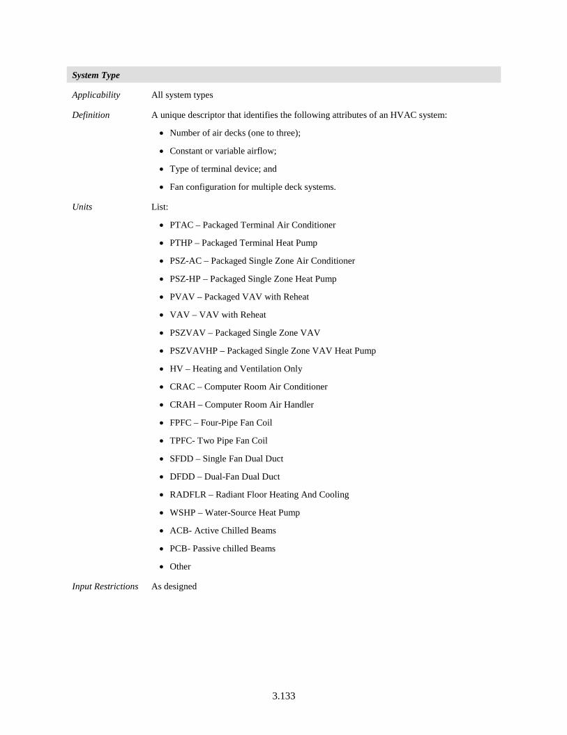
3.133
System Type
Applicability All system types
Definition A unique descriptor that identifies the following attributes of an HVAC system:
• Number of air decks (one to three);
• Constant or variable airflow;
• Type of terminal device; and
• Fan configuration for multiple deck systems.
Units List:
• PTAC – Packaged Terminal Air Conditioner
• PTHP – Packaged Terminal Heat Pump
• PSZ-AC – Packaged Single Zone Air Conditioner
• PSZ-HP – Packaged Single Zone Heat Pump
• PVAV – Packaged VAV with Reheat
• VAV – VAV with Reheat
• PSZVAV – Packaged Single Zone VAV
• PSZVAVHP – Packaged Single Zone VAV Heat Pump
• HV – Heating and Ventilation Only
• CRAC – Computer Room Air Conditioner
• CRAH – Computer Room Air Handler
• FPFC – Four-Pipe Fan Coil
• TPFC- Two Pipe Fan Coil
• SFDD – Single Fan Dual Duct
• DFDD – Dual-Fan Dual Duct
• RADFLR – Radiant Floor Heating And Cooling
• WSHP – Water-Source Heat Pump
• ACB- Active Chilled Beams
• PCB- Passive chilled Beams
• Other
Input Restrictions As designed
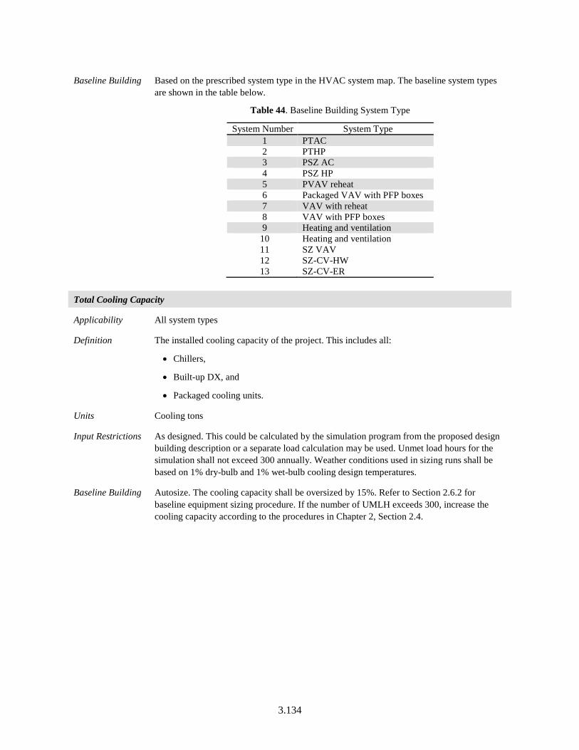
3.134
Baseline Building Based on the prescribed system type in the HVAC system map. The baseline system types are shown in the table below.
Table 44. Baseline Building System Type
System Number System Type 1 PTAC 2 PTHP 3 PSZ AC 4 PSZ HP 5 PVAV reheat 6 Packaged VAV with PFP boxes 7 VAV with reheat 8 VAV with PFP boxes 9 Heating and ventilation
10 Heating and ventilation 11 SZ VAV 12 SZ-CV-HW 13 SZ-CV-ER
Total Cooling Capacity
Applicability All system types
Definition The installed cooling capacity of the project. This includes all:
• Chillers,
• Built-up DX, and
• Packaged cooling units.
Units Cooling tons
Input Restrictions As designed. This could be calculated by the simulation program from the proposed design building description or a separate load calculation may be used. Unmet load hours for the simulation shall not exceed 300 annually. Weather conditions used in sizing runs shall be based on 1% dry-bulb and 1% wet-bulb cooling design temperatures.
Baseline Building Autosize. The cooling capacity shall be oversized by 15%. Refer to Section 2.6.2 for baseline equipment sizing procedure. If the number of UMLH exceeds 300, increase the cooling capacity according to the procedures in Chapter 2, Section 2.4.
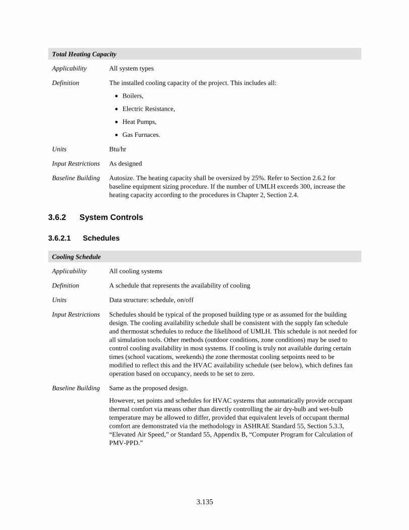
3.135
Total Heating Capacity
Applicability All system types
Definition The installed cooling capacity of the project. This includes all:
• Boilers,
• Electric Resistance,
• Heat Pumps,
• Gas Furnaces.
Units Btu/hr
Input Restrictions As designed
Baseline Building Autosize. The heating capacity shall be oversized by 25%. Refer to Section 2.6.2 for baseline equipment sizing procedure. If the number of UMLH exceeds 300, increase the heating capacity according to the procedures in Chapter 2, Section 2.4.
3.6.2 System Controls
3.6.2.1 Schedules
Cooling Schedule
Applicability All cooling systems
Definition A schedule that represents the availability of cooling
Units Data structure: schedule, on/off
Input Restrictions Schedules should be typical of the proposed building type or as assumed for the building design. The cooling availability schedule shall be consistent with the supply fan schedule and thermostat schedules to reduce the likelihood of UMLH. This schedule is not needed for all simulation tools. Other methods (outdoor conditions, zone conditions) may be used to control cooling availability in most systems. If cooling is truly not available during certain times (school vacations, weekends) the zone thermostat cooling setpoints need to be modified to reflect this and the HVAC availability schedule (see below), which defines fan operation based on occupancy, needs to be set to zero.
Baseline Building Same as the proposed design.
However, set points and schedules for HVAC systems that automatically provide occupant thermal comfort via means other than directly controlling the air dry-bulb and wet-bulb temperature may be allowed to differ, provided that equivalent levels of occupant thermal comfort are demonstrated via the methodology in ASHRAE Standard 55, Section 5.3.3, “Elevated Air Speed,” or Standard 55, Appendix B, “Computer Program for Calculation of PMV-PPD.”
3.136
Heating Schedule
Applicability All systems
Definition A schedule that represents the availability of heating
Units Data structure: schedule, on/off
Input Restrictions Schedules should be typical of the proposed building type or assumed for the building design. COMNET Appendix C (COMNET 2017) can be used as a default. The heating availability schedule shall be consistent with the supply fan schedule.
Baseline Building Same as the proposed design
However, set points and schedules for HVAC systems that automatically provide occupant thermal comfort via means other than directly controlling the air dry-bulb and wet-bulb temperature may be allowed to differ, provided that equivalent levels of occupant thermal comfort are demonstrated via the methodology in ASHRAE Standard 55, Section 5.3.3, “Elevated Air Speed,” or Standard 55, Appendix B, “Computer Program for Calculation of PMV-PPD.”
HVAC Availability Schedule
Applicability All systems
Definition A schedule that indicates when the air handler operates continuously
Units Data structure: schedule, on/off
Input Restrictions Schedules should be typical of the proposed building type or assumed for the building design. The fan schedule can be defaulted to the applicable schedule from COMNET Appendix C (COMNET 2017). Other schedules may be used when detailed information is known about the proposed design.
Baseline Building Same as the proposed design unless one baseline HVAC system serves a combination of systems in the proposed design with varying HVAC availability schedules. For those systems the HVAC availability schedule is determined by the most inclusive schedule represented in the proposed building design. If the most inclusive schedule does not cover the full range of availability, a hybrid schedule that does shall be created.
Air Handler Fan Cycling
Applicability All fan systems
Definition This building descriptor indicates whether the system supply fan operates continuously or cycles with building loads. The fan systems in most commercial buildings operate continuously during occupied hours.
Units List: Continuous or Cycles with Loads
Input Restrictions Schedules for HVAC fans shall run continuously whenever spaces are occupied and shall be cycled on and off to meet heating and cooling loads during unoccupied hours. Hours with occupancy >5% are considered to be occupied hours and require continuously operated fans.
3.137
Exceptions:
• HVAC fans that do not provide outdoor air for ventilation shall cycle on and off to meet heating and/or cooling loads. This requires that outdoor air is introduced through some other approved means such as natural ventilation or another fan system.
• Where no heating and/or cooling system is to be installed and a heating or cooling system is being simulated only to meet the requirements described in Standard 90.1-2016 PRM, heating and/or cooling system fans shall not be simulated as running continuously during occupied hours but shall be cycled on and off to meet heating and cooling loads during all hours.
• HVAC fans shall remain on during occupied and unoccupied hours in spaces that have health and safety mandated minimum ventilation requirements during unoccupied hours.
• HVAC fans shall remain on during occupied and unoccupied hours in systems primarily serving computer rooms
• For hotel guest rooms and high-rise residential, continuous operation is the default, however, the option to let the fan cycle with loads may be used when the following conditions are met and documented:
The spaces served by the system are located within 25 ft of an operable window.
The openable window area is at least 4% of the floor space.
Other requirements for natural ventilation specified in ASHRAE Standard 62.1-2016 are satisfied.
Baseline Building • HVAC fans shall run continuously whenever spaces are occupied and shall be cycled on and off to meet heating and cooling loads during unoccupied hours.
Except:
• HVAC fans shall remain on during occupied and unoccupied hours in systems primarily serving computer rooms
• HVAC fans shall remain on during occupied and unoccupied hours in spaces that have health and safety mandated minimum ventilation requirements during unoccupied hours.
3.138
Optimal Start Control
Applicability Systems with the control capability for flexible scheduling of system start time based on building loads
Definition Optimal start control adjusts the start time of the HVAC unit such that the space is brought to setpoint just prior to occupancy. This control strategy modifies the heating, cooling, and fan schedules.
Units Boolean (Yes/No)
Input Restrictions As designed
Heating and cooling systems with design air capacities greater than 10,000 cfm served by one or more supply fans are required to have optimum start controls.
Baseline Building Heating and cooling systems with design air capacity greater than 10,000 cfm served by one or more supply fans are required to have optimum start controls.
Optimal Start Control: Control Zone
Applicability Systems with optimal start controls that serve multiple zones
Definition The zone that governs the start time for applying optimal start controls
Units Boolean (Yes/No)
Input Restrictions List: “Any Zone,” all zones served by the system
Baseline Building Same as proposed
If optimal start controls are not required by the proposed design, but required in the baseline building, then this input will be set to “Any Zone”
3.6.2.2 Cooling Control
Cooling Supply Air Temperature
Applicability Applicable to all systems
Definition The SAT setpoint at design cooling conditions
Units Degrees Fahrenheit (°F)
Input Restrictions As designed
Baseline Building 20°F below the zone temperature setpoint, except in laboratories, where it is to be set at 17°F below the zone temperature
3.139
Cooling Supply Air Temperature Control
Applicability Any cooling system
Definition The method of controlling the SAT. Choices are:
• No control – for this scheme the cooling coils are energized whenever there is a call for cooling
• Fixed (constant)
• Reset by warmest zone, airflow first This control strategy resets the cooling SAT of a central forced air HVAC system according to the cooling demand of the warmest zone. The airflow first control approach tries to find the lowest supply airflow rate that will satisfy all the zone cooling loads at the maximum setpoint temperature. If this flow is greater than the maximum, the flow is set to the maximum and the setpoint temperature is reduced to satisfy the cooling loads. The airflow first strategy minimizes zone reheat coil energy (or overcooling) and central chiller energy consumption at the cost of possible increased fan energy.
• Reset by warmest zone, temperature first This control strategy resets the cooling SAT of a central forced air HVAC system according to the cooling demand of the warmest zone. The temperature first control approach tries to find the highest setpoint temperature that will satisfy all the zone cooling loads at the minimum supply airflow rate. If this setpoint temperature is less than the minimum, the setpoint temperature is set to the minimum, and the supply airflow rate is increased to meet the loads. The temperature first strategy minimizes fan energy consumption at the cost of possible increased zone reheat coil energy (or overcooling) and central chiller energy consumption.
• Reset by outside air dry-bulb temperature
• Scheduled setpoint
• Staged setpoint (for single zone VAV and DX with multiple stages)
Units List (see above)
Input Restrictions As designed
Baseline Building For baseline building systems 1 through 4, there is no SAT control. The cooling coil modulates based on the zone thermostat setpoint.
For systems 5 through 8, the air temperature for cooling shall be reset higher by 5°F under the minimum cooling load conditions using a reset by warmest zone, airflow first strategy.
For system 11, the supply air temperature setpoint shall be reset from minimum supply air temperature at 50% cooling load to space temperature at 0% cooling load.
For systems 9, 10, 12, and 13 (heating and ventilation and single zone systems), this input is not applicable.
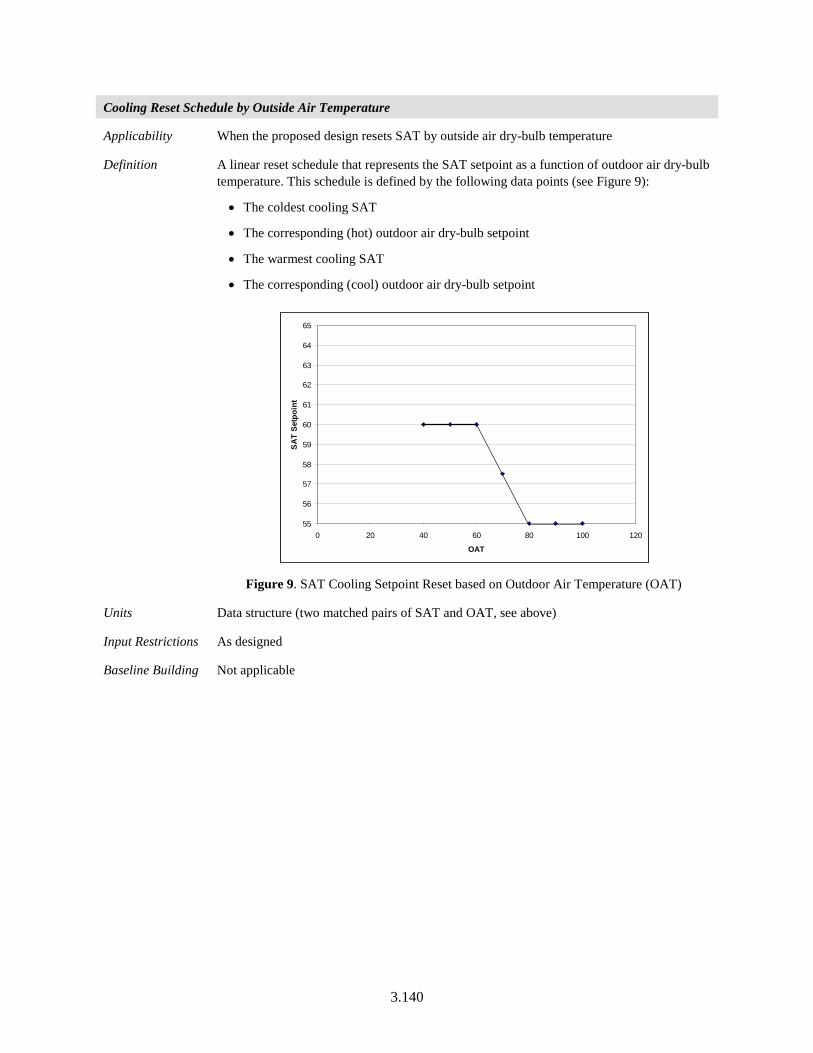
3.140
Cooling Reset Schedule by Outside Air Temperature
Applicability When the proposed design resets SAT by outside air dry-bulb temperature
Definition A linear reset schedule that represents the SAT setpoint as a function of outdoor air dry-bulb temperature. This schedule is defined by the following data points (see Figure 9):
• The coldest cooling SAT
• The corresponding (hot) outdoor air dry-bulb setpoint
• The warmest cooling SAT
• The corresponding (cool) outdoor air dry-bulb setpoint
Figure 9. SAT Cooling Setpoint Reset based on Outdoor Air Temperature (OAT)
Units Data structure (two matched pairs of SAT and OAT, see above)
Input Restrictions As designed
Baseline Building Not applicable
55
56
57
58
59
60
61
62
63
64
65
0 20 40 60 80 100 120
OAT
SAT
Setp
oint
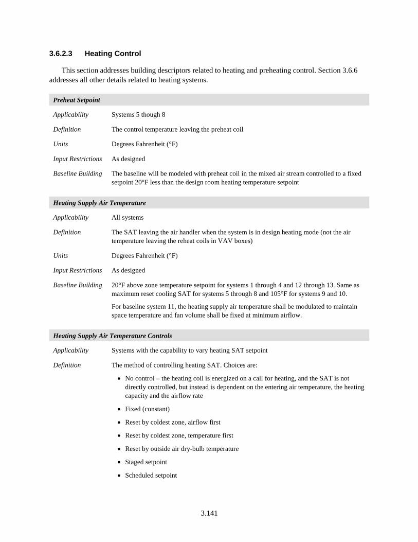
3.141
3.6.2.3 Heating Control
This section addresses building descriptors related to heating and preheating control. Section 3.6.6 addresses all other details related to heating systems.
Preheat Setpoint
Applicability Systems 5 though 8
Definition The control temperature leaving the preheat coil
Units Degrees Fahrenheit (°F)
Input Restrictions As designed
Baseline Building The baseline will be modeled with preheat coil in the mixed air stream controlled to a fixed setpoint 20°F less than the design room heating temperature setpoint
Heating Supply Air Temperature
Applicability All systems
Definition The SAT leaving the air handler when the system is in design heating mode (not the air temperature leaving the reheat coils in VAV boxes)
Units Degrees Fahrenheit (°F)
Input Restrictions As designed
Baseline Building 20°F above zone temperature setpoint for systems 1 through 4 and 12 through 13. Same as maximum reset cooling SAT for systems 5 through 8 and 105°F for systems 9 and 10.
For baseline system 11, the heating supply air temperature shall be modulated to maintain space temperature and fan volume shall be fixed at minimum airflow.
Heating Supply Air Temperature Controls
Applicability Systems with the capability to vary heating SAT setpoint
Definition The method of controlling heating SAT. Choices are:
• No control – the heating coil is energized on a call for heating, and the SAT is not directly controlled, but instead is dependent on the entering air temperature, the heating capacity and the airflow rate
• Fixed (constant)
• Reset by coldest zone, airflow first
• Reset by coldest zone, temperature first
• Reset by outside air dry-bulb temperature
• Staged setpoint
• Scheduled setpoint
3.142
Units Degrees Fahrenheit (°F)
Input Restrictions As designed
Baseline Building No control is specified for heating SAT for systems 1 through 4, 9, 10, and 11 through 13. For systems 5 through 8, the heating SAT is fixed to the maximum reset cooling SAT.
Heating Reset Schedule by Outside Air
Applicability Systems that reset the heating SAT by outside dry-bulb temperature (this typically applies to dual-duct systems or to single zone systems with hydronic heating coils)
Definition A linear reset schedule that represents the heating SAT or hot deck SAT (for dual duct systems) as a function of outdoor air dry-bulb temperature. This schedule is defined by the following data points (see Figure 10):
• The hottest heating SAT
• The corresponding (cold) outdoor air dry-bulb threshold
• The coolest heating SAT
• The corresponding (mild) outdoor air dry-bulb threshold
Figure 10. Example of SAT Heating Setpoint Reset based on Outdoor Air Temperature.
Units Data structure (°F)
Input Restrictions As designed
Baseline Building Not applicable
60
70
80
90
100
110
120
0 10 20 30 40 50 60 70 80 90
OAT
SAT
Setp
oint
3.143
3.6.2.4 Night Purge
The baseline building does not have night purge controls. If the software supports it and the proposed design has the features, the following keywords may be used to model night purge. Note that night purge is coupled with thermal mass in the building, which is specified by other building descriptors.
Night Purge Availability Schedule
Applicability Systems that operate the fans for nighttime purge of heat gains
Definition A schedule that represents the availability of night purge controls
Units Data structure: schedule, on/off
Input Restrictions As designed. The default is no night purge control.
Baseline Building Not applicable
Night Purge Control
Applicability Systems that operate the fans for nighttime purge of heat gains
Definition The control strategy for operation of nighttime purge. The control strategy may account for indoor temperature, season, and other factors.
Units Data structure
Input Restrictions As designed
Baseline Building Not applicable
Night Purge Fan Ratio
Applicability Systems that operate the fans for nighttime purge of heat gains
Definition The ratio of fan speed for a night purge cycle
Units Fraction (0 to 1)
Input Restrictions As designed. The default is 100% (or fans available at full speed).
Baseline Building Not applicable
3.6.3 Fan Systems
3.6.3.1 Baseline Building Fan System Summary
The baseline building fan system is summarized in this section. See Table 3 for the HVAC baseline building system mapping.
Total baseline building fan system power for the baseline building fan systems is given in the following sections as well as Table 46 and Table 47. Table 45 summarizes all descriptors for fan systems and their applicability to supply, return/relief, and exhaust fans.
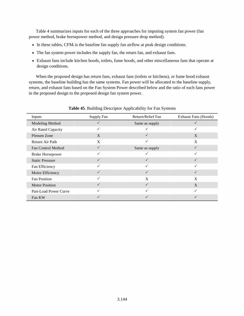
3.144
Table 4 summarizes inputs for each of the three approaches for imputing system fan power (fan power method, brake horsepower method, and design pressure drop method).
• In these tables, CFMs is the baseline fan supply fan airflow at peak design conditions.
• The fan system power includes the supply fan, the return fan, and exhaust fans.
• Exhaust fans include kitchen hoods, toilets, fume hoods, and other miscellaneous fans that operate at design conditions.
When the proposed design has return fans, exhaust fans (toilets or kitchens), or fume hood exhaust systems, the baseline building has the same systems. Fan power will be allocated to the baseline supply, return, and exhaust fans based on the Fan System Power described below and the ratio of each fans power in the proposed design to the proposed design fan system power.
Table 45. Building Descriptor Applicability for Fan Systems
Inputs Supply Fan Return/Relief Fan Exhaust Fans (Hoods)
Modeling Method Same as supply Air Rated Capacity Plenum Zone X X Return Air Path X X Fan Control Method Same as supply Brake Horsepower Static Pressure Fan Efficiency Motor Efficiency Fan Position X X Motor Position X Part-Load Power Curve Fan KW
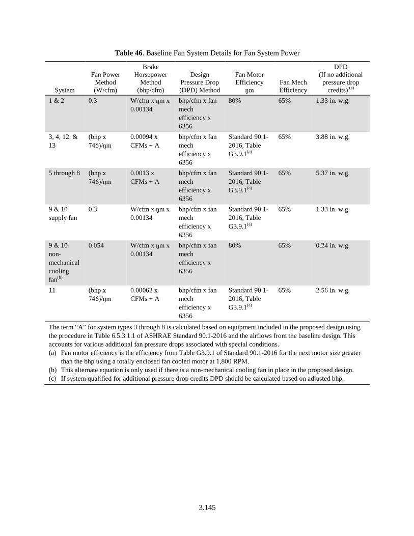
3.145
Table 46. Baseline Fan System Details for Fan System Power
System
Fan Power Method (W/cfm)
Brake Horsepower
Method (bhp/cfm)
Design Pressure Drop (DPD) Method
Fan Motor Efficiency
ŋm Fan Mech Efficiency
DPD (If no additional
pressure drop credits) (a)
1 & 2 0.3 W/cfm x ŋm x 0.00134
bhp/cfm x fan mech efficiency x 6356
80% 65% 1.33 in. w.g.
3, 4, 12. & 13
(bhp x 746)/ŋm
0.00094 x CFMs + A
bhp/cfm x fan mech efficiency x 6356
Standard 90.1-2016, Table G3.9.1(a)
65% 3.88 in. w.g.
5 through 8 (bhp x 746)/ŋm
0.0013 x CFMs + A
bhp/cfm x fan mech efficiency x 6356
Standard 90.1-2016, Table G3.9.1(a)
65% 5.37 in. w.g.
9 & 10 supply fan
0.3 W/cfm x ŋm x 0.00134
bhp/cfm x fan mech efficiency x 6356
Standard 90.1-2016, Table G3.9.1(a)
65% 1.33 in. w.g.
9 & 10 non-mechanical cooling fan(b)
0.054 W/cfm x ŋm x 0.00134
bhp/cfm x fan mech efficiency x 6356
80% 65% 0.24 in. w.g.
11 (bhp x 746)/ŋm
0.00062 x CFMs + A
bhp/cfm x fan mech efficiency x 6356
Standard 90.1-2016, Table G3.9.1(a)
65% 2.56 in. w.g.
The term “A” for system types 3 through 8 is calculated based on equipment included in the proposed design using the procedure in Table 6.5.3.1.1 of ASHRAE Standard 90.1-2016 and the airflows from the baseline design. This accounts for various additional fan pressure drops associated with special conditions. (a) Fan motor efficiency is the efficiency from Table G3.9.1 of Standard 90.1-2016 for the next motor size greater
than the bhp using a totally enclosed fan cooled motor at 1,800 RPM. (b) This alternate equation is only used if there is a non-mechanical cooling fan in place in the proposed design. (c) If system qualified for additional pressure drop credits DPD should be calculated based on adjusted bhp.
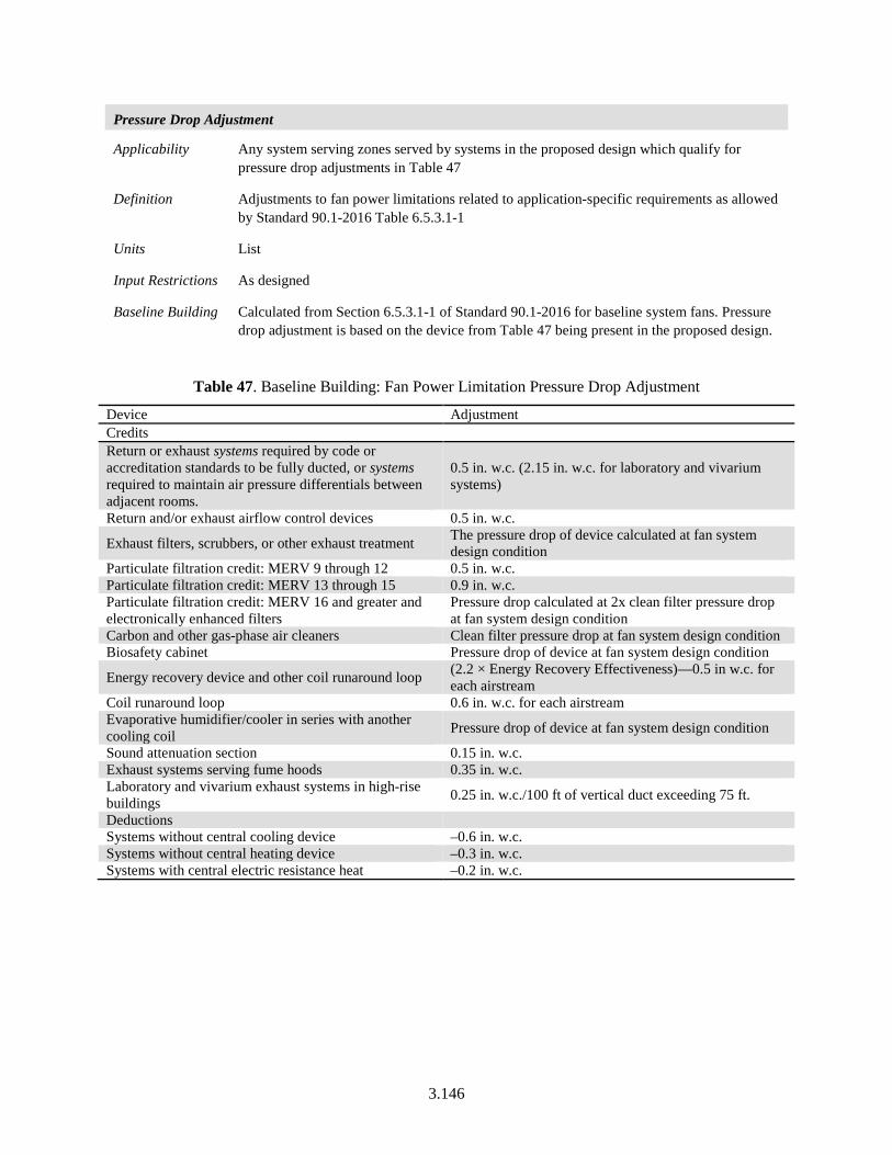
3.146
Pressure Drop Adjustment
Applicability Any system serving zones served by systems in the proposed design which qualify for pressure drop adjustments in Table 47
Definition Adjustments to fan power limitations related to application-specific requirements as allowed by Standard 90.1-2016 Table 6.5.3.1-1
Units List
Input Restrictions As designed
Baseline Building Calculated from Section 6.5.3.1-1 of Standard 90.1-2016 for baseline system fans. Pressure drop adjustment is based on the device from Table 47 being present in the proposed design.
Table 47. Baseline Building: Fan Power Limitation Pressure Drop Adjustment
Device Adjustment Credits Return or exhaust systems required by code or accreditation standards to be fully ducted, or systems required to maintain air pressure differentials between adjacent rooms.
0.5 in. w.c. (2.15 in. w.c. for laboratory and vivarium systems)
Return and/or exhaust airflow control devices 0.5 in. w.c.
Exhaust filters, scrubbers, or other exhaust treatment The pressure drop of device calculated at fan system design condition
Particulate filtration credit: MERV 9 through 12 0.5 in. w.c. Particulate filtration credit: MERV 13 through 15 0.9 in. w.c. Particulate filtration credit: MERV 16 and greater and electronically enhanced filters
Pressure drop calculated at 2x clean filter pressure drop at fan system design condition
Carbon and other gas-phase air cleaners Clean filter pressure drop at fan system design condition Biosafety cabinet Pressure drop of device at fan system design condition
Energy recovery device and other coil runaround loop (2.2 × Energy Recovery Effectiveness)—0.5 in w.c. for each airstream
Coil runaround loop 0.6 in. w.c. for each airstream Evaporative humidifier/cooler in series with another cooling coil Pressure drop of device at fan system design condition
Sound attenuation section 0.15 in. w.c. Exhaust systems serving fume hoods 0.35 in. w.c. Laboratory and vivarium exhaust systems in high-rise buildings 0.25 in. w.c./100 ft of vertical duct exceeding 75 ft.
Deductions Systems without central cooling device –0.6 in. w.c. Systems without central heating device –0.3 in. w.c. Systems with central electric resistance heat –0.2 in. w.c.
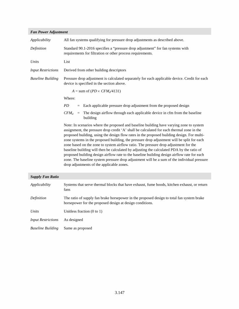
3.147
Fan Power Adjustment
Applicability All fan systems qualifying for pressure drop adjustments as described above.
Definition Standard 90.1-2016 specifies a “pressure drop adjustment” for fan systems with requirements for filtration or other process requirements.
Units List
Input Restrictions Derived from other building descriptors
Baseline Building Pressure drop adjustment is calculated separately for each applicable device. Credit for each device is specified in the section above.
A = sum of (PD × CFMd/4131)
Where:
PD = Each applicable pressure drop adjustment from the proposed design
CFMd = The design airflow through each applicable device in cfm from the baseline building
Note: In scenarios where the proposed and baseline building have varying zone to system assignment, the pressure drop credit ‘A’ shall be calculated for each thermal zone in the proposed building, using the design flow rates in the proposed building design. For multi-zone systems in the proposed building, the pressure drop adjustment will be split for each zone based on the zone to system airflow ratio. The pressure drop adjustment for the baseline building will then be calculated by adjusting the calculated PDA by the ratio of proposed building design airflow rate to the baseline building design airflow rate for each zone. The baseline system pressure drop adjustment will be a sum of the individual pressure drop adjustments of the applicable zones.
Supply Fan Ratio
Applicability Systems that serve thermal blocks that have exhaust, fume hoods, kitchen exhaust, or return fans
Definition The ratio of supply fan brake horsepower in the proposed design to total fan system brake horsepower for the proposed design at design conditions.
Units Unitless fraction (0 to 1)
Input Restrictions As designed
Baseline Building Same as proposed
3.148
Return Fan Ratio
Applicability Systems that serve thermal blocks that have exhaust, fume hoods, kitchen exhaust, or return fans
Definition The ratio of return fan brake horsepower in the proposed design to total fan system brake horsepower for the proposed design at design conditions
Units Unitless fraction (0 to 1)
Input Restrictions Derived from other building descriptors
Baseline Building Same as proposed
Exhaust Fan Ratio
Applicability Systems that serve thermal blocks that have exhaust, fume hoods, kitchen exhaust, or return fans
Definition The ratio of exhaust fan brake horsepower in the proposed design to total fan system brake hp for the proposed design at design conditions. Exhaust fans include toilet exhaust, kitchen hoods, and other miscellaneous exhaust.
For fan systems with multiple exhaust fans, the exhaust fan ratios shall be calculated separately for each exhaust fan.
Units Unitless ratio
Input Restrictions Derived from other building descriptors. In the event that a common exhaust system serves thermal blocks that are served by different HVAC systems, the brake horsepower shall be divided in proportion to design cfm.
Baseline Building Same as proposed
3.149
3.6.3.2 Supply Fans
Fan System Modeling Method
Applicability All fan systems
Definition Software commonly models fans in three ways. The simple method is for the user to enter the electric power per unit of flow (W/cfm). This method is commonly used for unitary equipment and other small fan systems. A more detailed method is to model the fan as a system whereby the static pressure, fan efficiency, and motor efficiency are specified at design conditions. A third method is to specify brake horsepower at design conditions instead of fan efficiency and static pressure. This is a variation of the second method whereby brake horsepower is specified in lieu of static pressure and fan efficiency.
Units List: Power-Per-Unit-Flow, Design Pressure Drop, or Brake Horsepower
Input Restrictions As designed
Baseline Building Systems 1, 2, 9, and 10 should use power per unit flow if allowed by the software. If not allowed used one of the other methods as described in Table 47. All other baseline system shall use the brake horsepower method. If that method is not available, static pressure method should be used.
Supply Fan Design Air Rated Capacity
Applicability All fan systems
Definition The design airflow rate of the supply fan(s) at design conditions. This building descriptor sets the 100% point for the fan part-load curve.
Units cfm
Input Restrictions As designed
Baseline Building The software shall automatically size the system airflow to meet the baseline building loads based on
• a supply-air-to-room-air temperature difference of 20°F,
• or the minimum outdoor airflow rate,
• or the airflow rate required to comply with the applicable codes or accreditation standards, whichever is greater.
The baseline system airflow is determined by the load to be met by the airflow and the 20°F (11°C) temperature difference. The loads to be used would be the design load as determined by the sizing runs specified in Section G3.1.2.2, not the cooling or heating capacity of the system as determined using the sizing factors, also specified in G3.1.2.2. Using the system cooling and heating capacity will result in oversized baseline system airflows and energy cost because of the oversizing factors used in G3.1.2.2.
See additional discussion in Section 3.5.5.1 for VAV systems. spaces with special process requirements.) The supply fan design airflow rate shall be the sum of the calculated design airflow for the thermal zones served by the fan system.
3.150
For laboratory spaces, the design airflow rate calculation shall be based on a 17°F temperature differential rather than 20°F.
For baseline systems 9 and 10, the design supply airflow rates shall be based on the temperature difference between a SAT setpoint of 105°F and the design space heating temperature setpoint, the minimum outdoor airflow rate or the airflow rate required to comply with applicable codes, whichever is greater.
If the proposed design HVAC system airflow rate based on latent loads greater than the same based on sensible loads, then the same supply-air-to-room humidity ratio difference (gr/lb) used to calculate the proposed design airflow should be used to calculate the design airflow rates for the baseline building.
Fan Control Method
Applicability All fan systems
Definition A description of how the supply (and return/relief) fan(s) is controlled. The options include:
• Constant volume
• Variable-flow, inlet or discharge dampers
• Variable-flow, inlet guide vanes
• Variable-flow, variable speed drive (VSD)
• Variable-flow, variable pitch blades
• Variable-flow, other
• Two-speed
• Constant volume, cycling (fan cycles with heating and cooling)
Units List (see above)
Input Restrictions As designed
Baseline Building Based on the baseline system type, summarized in Table 48
3.151
Table 48. Baseline Building Fan Control Method
System No. System Type Fan Control System 1 Package terminal air conditioner Constant volume System 2 Packaged terminal heat pump Constant volume System 3 Packaged roof top air conditioner Constant volume System 4 Packaged roof top heat pump Constant volume
System 5 Packaged rooftop VAV with reheat Variable volume, variable speed drive (VSD)
System 6 Packaged rooftop VAV with PFP boxes and reheat Variable volume, VSD System 7 Packaged rooftop VAV with reheat Variable volume, VSD System 8 VAV with parallel fan-powered boxes and reheat Variable volume, VSD System 9 Warm air furnace, gas fired Constant volume
System 10 Warm air furnace, electric Constant volume System 11 Single zone VAV Variable volume, VSD System 12 Single zone system (CHW and HW boiler) Constant volume System 13 Single zone system (CHW and electric resistance) Constant volume
Supply Fan Brake Horsepower
Applicability All fan systems, except those specified using the power-per-unit-flow method
Definition The design shaft brake horsepower of the supply fan(s). This input does not need to be supplied if the supply fan kW is supplied.
Units Horsepower (hp)
Input Restrictions As designed. If this building descriptor is specified for the proposed design, then the static pressure and fan efficiency are not required.
Baseline Building Fans for parallel fan-powered boxes are not included in fan power calculations.
Table 46 of this document gives the baseline building fan system brake horsepower. The brake horsepower for the supply fan is this value times the supply fan ratio (see above).
Supply Fan Static Pressure
Applicability All fan systems, except those specified using the power-per-unit-flow method
Definition The design static pressure for the supply fan. This is important for both fan electric energy usage and duct heat gain calculations.
Units Inches of water column (in. H2O)
Input Restrictions As designed. The design static pressure for the supply fan does not need to be specified if the supply fan brake horsepower (bhp) is specified.
Baseline Building The baseline building is defined by Table. This approach only works if the system has only a supply fan. If return/exhaust fans are also present in the system, then the supply fan bhp needs to be calculated and divided amongst the supply, return, and exhaust fans.
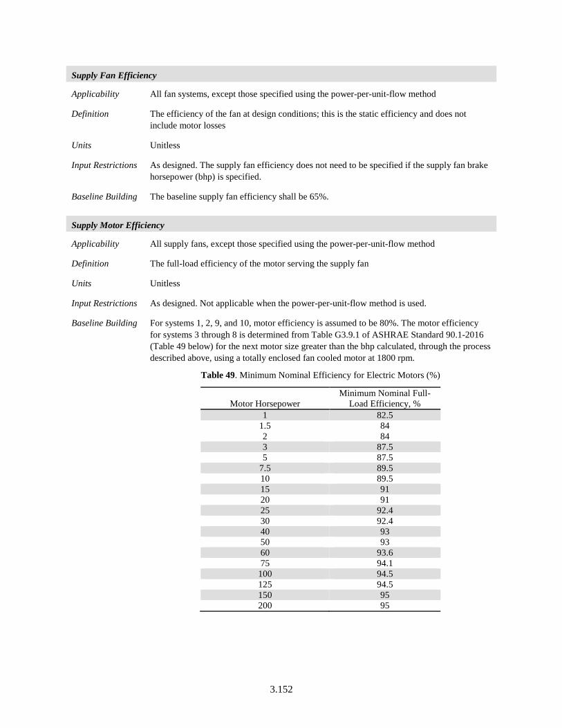
3.152
Supply Fan Efficiency
Applicability All fan systems, except those specified using the power-per-unit-flow method
Definition The efficiency of the fan at design conditions; this is the static efficiency and does not include motor losses
Units Unitless
Input Restrictions As designed. The supply fan efficiency does not need to be specified if the supply fan brake horsepower (bhp) is specified.
Baseline Building The baseline supply fan efficiency shall be 65%.
Supply Motor Efficiency
Applicability All supply fans, except those specified using the power-per-unit-flow method
Definition The full-load efficiency of the motor serving the supply fan
Units Unitless
Input Restrictions As designed. Not applicable when the power-per-unit-flow method is used.
Baseline Building For systems 1, 2, 9, and 10, motor efficiency is assumed to be 80%. The motor efficiency for systems 3 through 8 is determined from Table G3.9.1 of ASHRAE Standard 90.1-2016 (Table 49 below) for the next motor size greater than the bhp calculated, through the process described above, using a totally enclosed fan cooled motor at 1800 rpm.
Table 49. Minimum Nominal Efficiency for Electric Motors (%)
Motor Horsepower Minimum Nominal Full-
Load Efficiency, % 1 82.5
1.5 84 2 84 3 87.5 5 87.5
7.5 89.5 10 89.5 15 91 20 91 25 92.4 30 92.4 40 93 50 93 60 93.6 75 94.1
100 94.5 125 94.5 150 95 200 95
3.153
Fan Position
Applicability All supply fans
Definition The position of the supply fan relative to the cooling coil. The configuration is either draw through (fan is downstream of the coil) or blow through (fan is upstream of the coil).
Units List (see above)
Input Restrictions As designed
Baseline Building Draw through
Motor Position
Applicability All supply fans
Definition The position of the supply fan motor relative to the cooling air stream. The choices are: in the air stream or out of the air stream.
Units List (see above)
Input Restrictions As designed
Baseline Building In the air stream
Fan Part-Flow Power Curve
Applicability All variable flow fan systems
Definition A part-load power curve that represents the percentage full-load power draw of the supply fan as a function of the percentage full-load airflow. The curve is typically represented as a cubic equation with an absolute minimum power draw specified.
Units Unitless ratio
Input Restrictions The fan curve shall be selected from Equation (11) and Table 50 for the type of fan specified in the proposed design.
PowerMinPLRFanRatiodFanRatiocFanRatiobaPLR
ofGreater
=⋅+⋅+⋅+= 32
(11)
Where:
PLR = Ratio of fan power at part load conditions to full load fan power
PowerMin = Minimum fan power ratio
FanRatio = Ratio of cfm at part-load to full-load cfm
a, b, c and d = Constants from Table 50
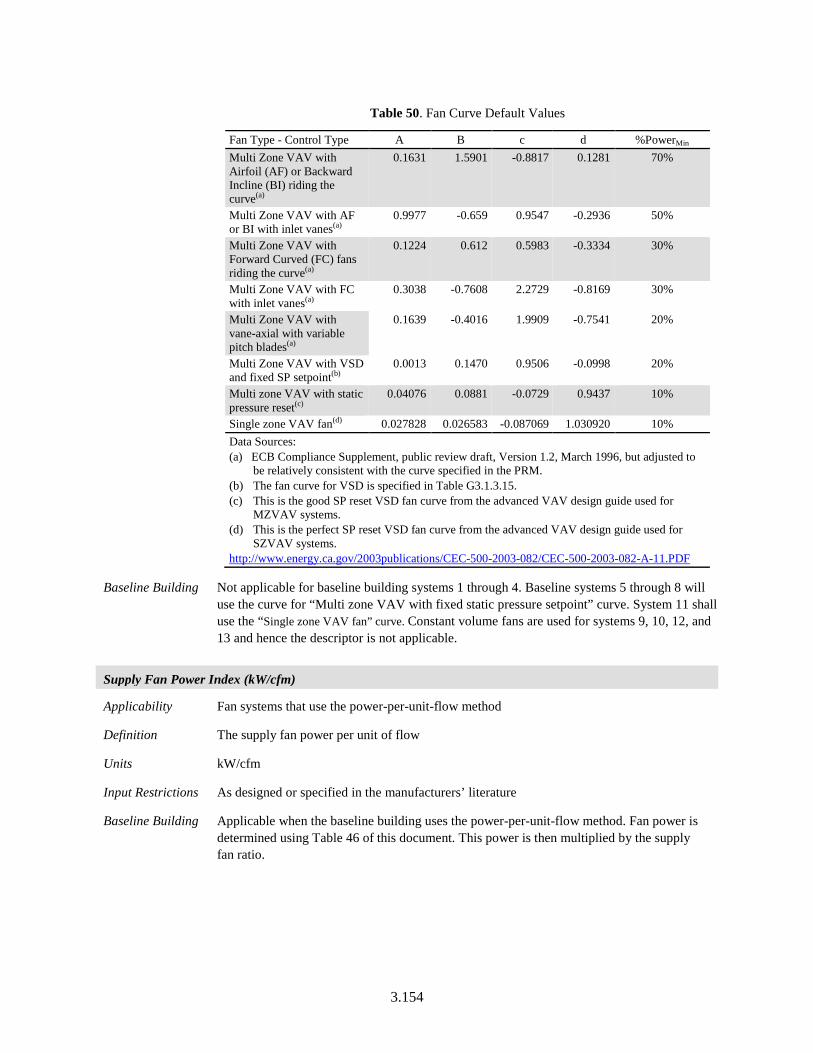
3.154
Table 50. Fan Curve Default Values
Fan Type - Control Type A B c d %PowerMin Multi Zone VAV with Airfoil (AF) or Backward Incline (BI) riding the curve(a)
0.1631 1.5901 -0.8817 0.1281 70%
Multi Zone VAV with AF or BI with inlet vanes(a)
0.9977 -0.659 0.9547 -0.2936 50%
Multi Zone VAV with Forward Curved (FC) fans riding the curve(a)
0.1224 0.612 0.5983 -0.3334 30%
Multi Zone VAV with FC with inlet vanes(a)
0.3038 -0.7608 2.2729 -0.8169 30%
Multi Zone VAV with vane-axial with variable pitch blades(a)
0.1639 -0.4016 1.9909 -0.7541 20%
Multi Zone VAV with VSD and fixed SP setpoint(b)
0.0013 0.1470 0.9506 -0.0998 20%
Multi zone VAV with static pressure reset(c)
0.04076 0.0881 -0.0729 0.9437 10%
Single zone VAV fan(d) 0.027828 0.026583 -0.087069 1.030920 10% Data Sources: (a) ECB Compliance Supplement, public review draft, Version 1.2, March 1996, but adjusted to
be relatively consistent with the curve specified in the PRM. (b) The fan curve for VSD is specified in Table G3.1.3.15. (c) This is the good SP reset VSD fan curve from the advanced VAV design guide used for
MZVAV systems. (d) This is the perfect SP reset VSD fan curve from the advanced VAV design guide used for
SZVAV systems. http://www.energy.ca.gov/2003publications/CEC-500-2003-082/CEC-500-2003-082-A-11.PDF
Baseline Building Not applicable for baseline building systems 1 through 4. Baseline systems 5 through 8 will use the curve for “Multi zone VAV with fixed static pressure setpoint” curve. System 11 shall use the “Single zone VAV fan” curve. Constant volume fans are used for systems 9, 10, 12, and 13 and hence the descriptor is not applicable.
Supply Fan Power Index (kW/cfm)
Applicability Fan systems that use the power-per-unit-flow method
Definition The supply fan power per unit of flow
Units kW/cfm
Input Restrictions As designed or specified in the manufacturers’ literature
Baseline Building Applicable when the baseline building uses the power-per-unit-flow method. Fan power is determined using Table 46 of this document. This power is then multiplied by the supply fan ratio.
3.155
Static Pressure Reset Controls
Applicability All VAV fan systems. Baseline systems 5 through 8.
Definition Static pressure reset controls, reset the fan static pressure for VAV systems-based zone damper position. For systems with DDC of individual zone boxes reporting to the central control panel, static pressure setpoint shall be reset based on the zone requiring the most pressure.
Units Unitless
Input Restrictions As designed. If static pressure reset is implemented in the proposed system, the curve for “Multi zone VAV with static pressure reset curve” shall be used.
Baseline Building Not applicable for baseline building systems 1 through 4 or 9, 10, 11, 12, and 13. The curve for “Multi Zone VAV with VSD and fixed SP setpoint”’ shall be used for baseline building systems 5 through 8.
3.6.3.3 Return/Relief Fans
System design supply airflow rates for the baseline building design shall be based on a supply-air-to room-air temperature difference of 20°F or the minimum outdoor airflow rate, or the airflow rate required to comply with applicable codes or accreditation standards, whichever is greater. For systems 3, 4, and 11 through 13, if return or relief fans are specified for systems serving the corresponding zones in the proposed design, the baseline building design shall also be modeled with fans serving the same functions. For systems 5 through 8, if return or relief fans are specified in the proposed building, then the baseline systems serving the corresponding zones will be modeled with a return/relief fan.
Plenum Zone
Applicability Any system with return ducts or return air plenum
Definition A reference to the thermal zone that serves as return plenum or where the return ducts are located
Units Text, unique
Input Restrictions As designed
Baseline Building Applicable when the baseline building has a return fan. Same as the proposed design when the proposed design has a plenum; otherwise, the return air ducts are assumed to be located in the space.
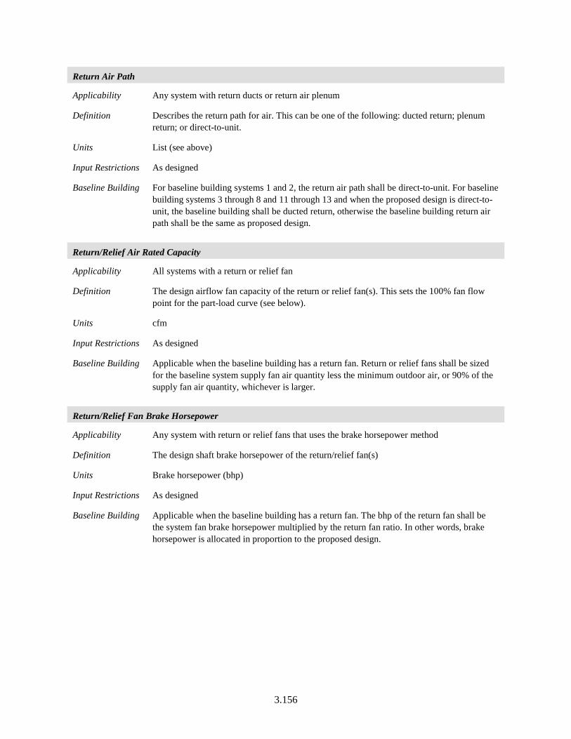
3.156
Return Air Path
Applicability Any system with return ducts or return air plenum
Definition Describes the return path for air. This can be one of the following: ducted return; plenum return; or direct-to-unit.
Units List (see above)
Input Restrictions As designed
Baseline Building For baseline building systems 1 and 2, the return air path shall be direct-to-unit. For baseline building systems 3 through 8 and 11 through 13 and when the proposed design is direct-to-unit, the baseline building shall be ducted return, otherwise the baseline building return air path shall be the same as proposed design.
Return/Relief Air Rated Capacity
Applicability All systems with a return or relief fan
Definition The design airflow fan capacity of the return or relief fan(s). This sets the 100% fan flow point for the part-load curve (see below).
Units cfm
Input Restrictions As designed
Baseline Building Applicable when the baseline building has a return fan. Return or relief fans shall be sized for the baseline system supply fan air quantity less the minimum outdoor air, or 90% of the supply fan air quantity, whichever is larger.
Return/Relief Fan Brake Horsepower
Applicability Any system with return or relief fans that uses the brake horsepower method
Definition The design shaft brake horsepower of the return/relief fan(s)
Units Brake horsepower (bhp)
Input Restrictions As designed
Baseline Building Applicable when the baseline building has a return fan. The bhp of the return fan shall be the system fan brake horsepower multiplied by the return fan ratio. In other words, brake horsepower is allocated in proportion to the proposed design.
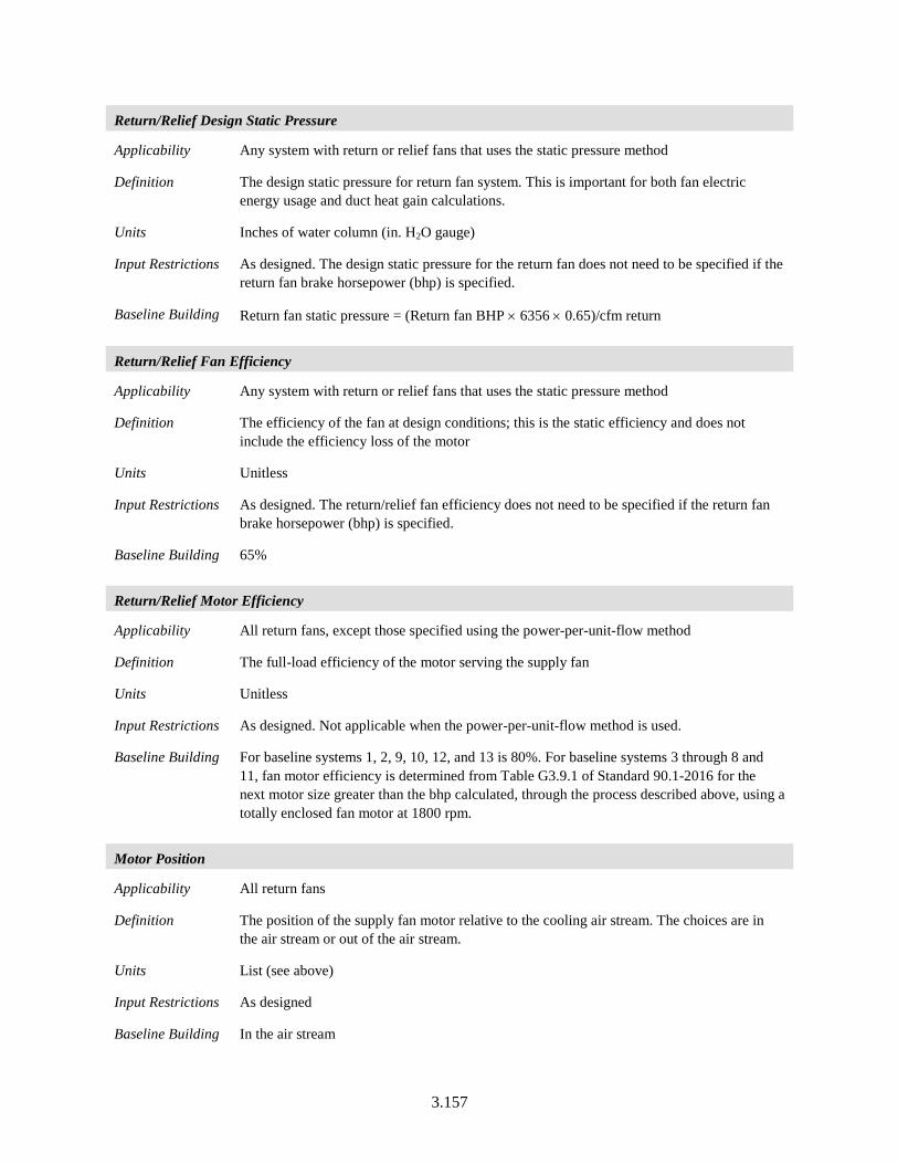
3.157
Return/Relief Design Static Pressure
Applicability Any system with return or relief fans that uses the static pressure method
Definition The design static pressure for return fan system. This is important for both fan electric energy usage and duct heat gain calculations.
Units Inches of water column (in. H2O gauge)
Input Restrictions As designed. The design static pressure for the return fan does not need to be specified if the return fan brake horsepower (bhp) is specified.
Baseline Building Return fan static pressure = (Return fan BHP × 6356 × 0.65)/cfm return
Return/Relief Fan Efficiency
Applicability Any system with return or relief fans that uses the static pressure method
Definition The efficiency of the fan at design conditions; this is the static efficiency and does not include the efficiency loss of the motor
Units Unitless
Input Restrictions As designed. The return/relief fan efficiency does not need to be specified if the return fan brake horsepower (bhp) is specified.
Baseline Building 65%
Return/Relief Motor Efficiency
Applicability All return fans, except those specified using the power-per-unit-flow method
Definition The full-load efficiency of the motor serving the supply fan
Units Unitless
Input Restrictions As designed. Not applicable when the power-per-unit-flow method is used.
Baseline Building For baseline systems 1, 2, 9, 10, 12, and 13 is 80%. For baseline systems 3 through 8 and 11, fan motor efficiency is determined from Table G3.9.1 of Standard 90.1-2016 for the next motor size greater than the bhp calculated, through the process described above, using a totally enclosed fan motor at 1800 rpm.
Motor Position
Applicability All return fans
Definition The position of the supply fan motor relative to the cooling air stream. The choices are in the air stream or out of the air stream.
Units List (see above)
Input Restrictions As designed
Baseline Building In the air stream
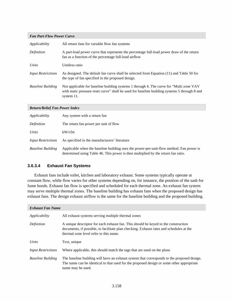
3.158
Fan Part-Flow Power Curve
Applicability All return fans for variable flow fan systems
Definition A part-load power curve that represents the percentage full-load power draw of the return fan as a function of the percentage full-load airflow
Units Unitless ratio
Input Restrictions As designed. The default fan curve shall be selected from Equation (11) and Table 50 for the type of fan specified in the proposed design.
Baseline Building Not applicable for baseline building systems 1 through 4. The curve for “Multi zone VAV with static pressure reset curve” shall be used for baseline building systems 5 through 8 and system 11.
Return/Relief Fan Power Index
Applicability Any system with a return fan
Definition The return fan power per unit of flow
Units kW/cfm
Input Restrictions As specified in the manufacturers’ literature
Baseline Building Applicable when the baseline building uses the power-per-unit-flow method. Fan power is determined using Table 46. This power is then multiplied by the return fan ratio.
3.6.3.4 Exhaust Fan Systems
Exhaust fans include toilet, kitchen and laboratory exhaust. Some systems typically operate at constant flow, while flow varies for other systems depending on, for instance, the position of the sash for fume hoods. Exhaust fan flow is specified and scheduled for each thermal zone. An exhaust fan system may serve multiple thermal zones. The baseline building has exhaust fans when the proposed design has exhaust fans. The design exhaust airflow is the same for the baseline building and the proposed building.
Exhaust Fan Name
Applicability All exhaust systems serving multiple thermal zones
Definition A unique descriptor for each exhaust fan. This should be keyed to the construction documents, if possible, to facilitate plan checking. Exhaust rates and schedules at the thermal zone level refer to this name.
Units Text, unique
Input Restrictions Where applicable, this should match the tags that are used on the plans
Baseline Building The baseline building will have an exhaust system that corresponds to the proposed design. The name can be identical to that used for the proposed design or some other appropriate name may be used.
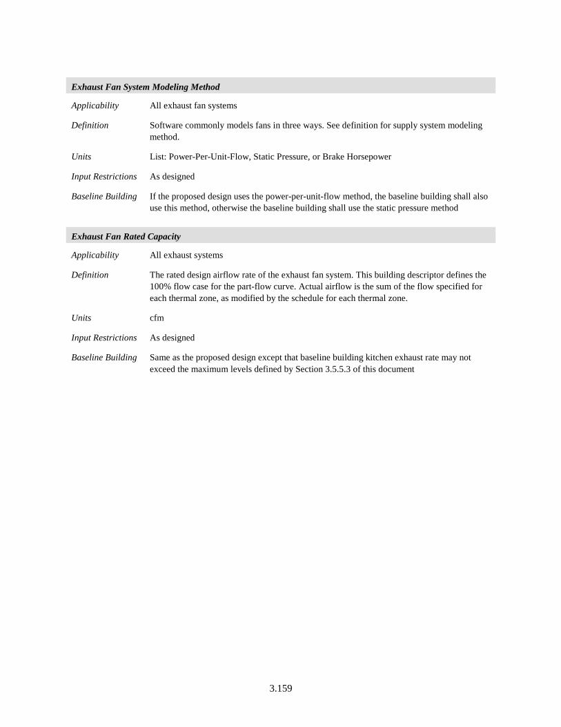
3.159
Exhaust Fan System Modeling Method
Applicability All exhaust fan systems
Definition Software commonly models fans in three ways. See definition for supply system modeling method.
Units List: Power-Per-Unit-Flow, Static Pressure, or Brake Horsepower
Input Restrictions As designed
Baseline Building If the proposed design uses the power-per-unit-flow method, the baseline building shall also use this method, otherwise the baseline building shall use the static pressure method
Exhaust Fan Rated Capacity
Applicability All exhaust systems
Definition The rated design airflow rate of the exhaust fan system. This building descriptor defines the 100% flow case for the part-flow curve. Actual airflow is the sum of the flow specified for each thermal zone, as modified by the schedule for each thermal zone.
Units cfm
Input Restrictions As designed
Baseline Building Same as the proposed design except that baseline building kitchen exhaust rate may not exceed the maximum levels defined by Section 3.5.5.3 of this document
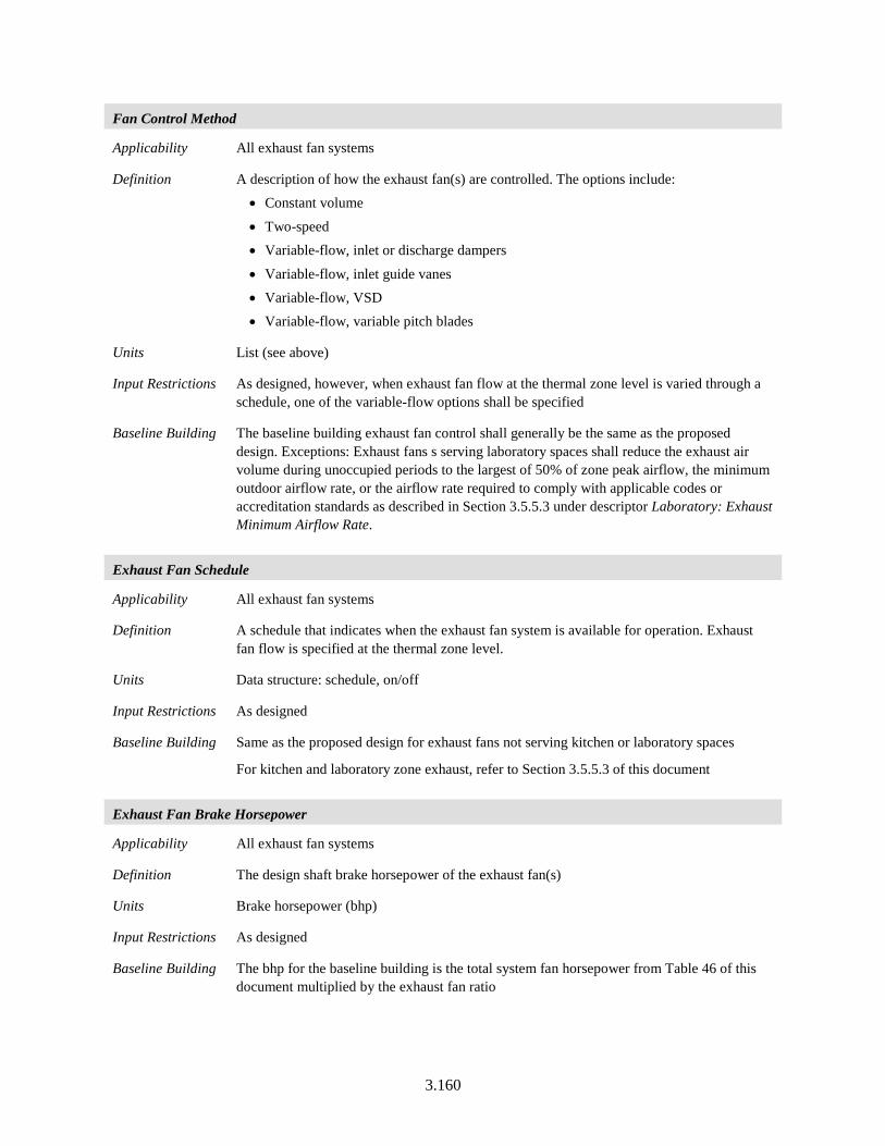
3.160
Fan Control Method
Applicability All exhaust fan systems
Definition A description of how the exhaust fan(s) are controlled. The options include: • Constant volume
• Two-speed • Variable-flow, inlet or discharge dampers
• Variable-flow, inlet guide vanes • Variable-flow, VSD • Variable-flow, variable pitch blades
Units List (see above)
Input Restrictions As designed, however, when exhaust fan flow at the thermal zone level is varied through a schedule, one of the variable-flow options shall be specified
Baseline Building The baseline building exhaust fan control shall generally be the same as the proposed design. Exceptions: Exhaust fans s serving laboratory spaces shall reduce the exhaust air volume during unoccupied periods to the largest of 50% of zone peak airflow, the minimum outdoor airflow rate, or the airflow rate required to comply with applicable codes or accreditation standards as described in Section 3.5.5.3 under descriptor Laboratory: Exhaust Minimum Airflow Rate.
Exhaust Fan Schedule
Applicability All exhaust fan systems
Definition A schedule that indicates when the exhaust fan system is available for operation. Exhaust fan flow is specified at the thermal zone level.
Units Data structure: schedule, on/off
Input Restrictions As designed
Baseline Building Same as the proposed design for exhaust fans not serving kitchen or laboratory spaces
For kitchen and laboratory zone exhaust, refer to Section 3.5.5.3 of this document
Exhaust Fan Brake Horsepower
Applicability All exhaust fan systems
Definition The design shaft brake horsepower of the exhaust fan(s)
Units Brake horsepower (bhp)
Input Restrictions As designed
Baseline Building The bhp for the baseline building is the total system fan horsepower from Table 46 of this document multiplied by the exhaust fan ratio
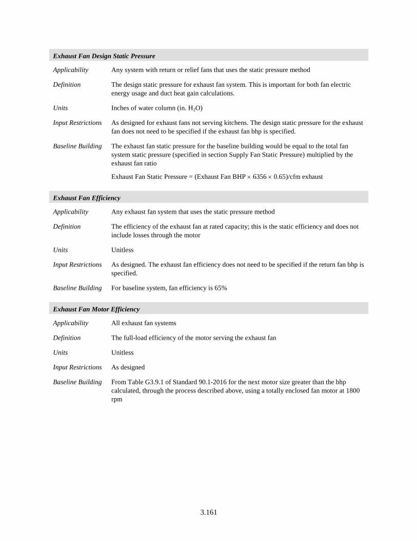
3.161
Exhaust Fan Design Static Pressure
Applicability Any system with return or relief fans that uses the static pressure method
Definition The design static pressure for exhaust fan system. This is important for both fan electric energy usage and duct heat gain calculations.
Units Inches of water column (in. H2O)
Input Restrictions As designed for exhaust fans not serving kitchens. The design static pressure for the exhaust fan does not need to be specified if the exhaust fan bhp is specified.
Baseline Building The exhaust fan static pressure for the baseline building would be equal to the total fan system static pressure (specified in section Supply Fan Static Pressure) multiplied by the exhaust fan ratio
Exhaust Fan Static Pressure = (Exhaust Fan BHP × 6356 × 0.65)/cfm exhaust
Exhaust Fan Efficiency
Applicability Any exhaust fan system that uses the static pressure method
Definition The efficiency of the exhaust fan at rated capacity; this is the static efficiency and does not include losses through the motor
Units Unitless
Input Restrictions As designed. The exhaust fan efficiency does not need to be specified if the return fan bhp is specified.
Baseline Building For baseline system, fan efficiency is 65%
Exhaust Fan Motor Efficiency
Applicability All exhaust fan systems
Definition The full-load efficiency of the motor serving the exhaust fan
Units Unitless
Input Restrictions As designed
Baseline Building From Table G3.9.1 of Standard 90.1-2016 for the next motor size greater than the bhp calculated, through the process described above, using a totally enclosed fan motor at 1800 rpm
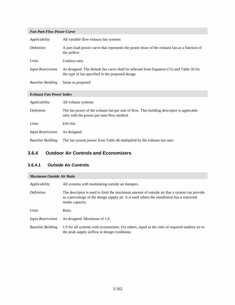
3.162
Fan Part-Flow Power Curve
Applicability All variable flow exhaust fan systems
Definition A part-load power curve that represents the power draw of the exhaust fan as a function of the airflow
Units Unitless ratio
Input Restrictions As designed. The default fan curve shall be selected from Equation (11) and Table 50 for the type of fan specified in the proposed design.
Baseline Building Same as proposed
Exhaust Fan Power Index
Applicability All exhaust systems
Definition The fan power of the exhaust fan per unit of flow. This building descriptor is applicable only with the power-per-unit-flow method.
Units kW/cfm
Input Restrictions As designed
Baseline Building The fan system power from Table 46 multiplied by the exhaust fan ratio
3.6.4 Outdoor Air Controls and Economizers
3.6.4.1 Outside Air Controls
Maximum Outside Air Ratio
Applicability All systems with modulating outside air dampers
Definition The descriptor is used to limit the maximum amount of outside air that a system can provide as a percentage of the design supply air. It is used where the installation has a restricted intake capacity.
Units Ratio
Input Restrictions As designed. Maximum of 1.0.
Baseline Building 1.0 for all systems with economizers. For others, equal to the ratio of required outdoor air to the peak supply airflow at design conditions.
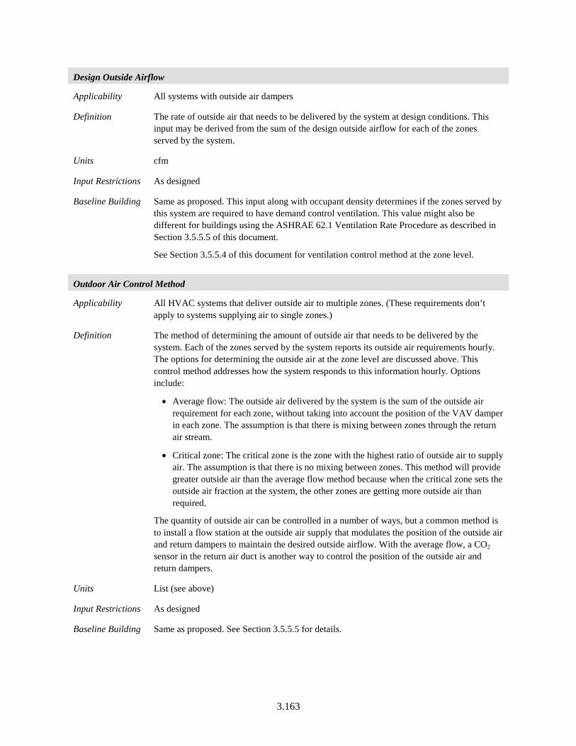
3.163
Design Outside Airflow
Applicability All systems with outside air dampers
Definition The rate of outside air that needs to be delivered by the system at design conditions. This input may be derived from the sum of the design outside airflow for each of the zones served by the system.
Units cfm
Input Restrictions As designed
Baseline Building Same as proposed. This input along with occupant density determines if the zones served by this system are required to have demand control ventilation. This value might also be different for buildings using the ASHRAE 62.1 Ventilation Rate Procedure as described in Section 3.5.5.5 of this document.
See Section 3.5.5.4 of this document for ventilation control method at the zone level.
Outdoor Air Control Method
Applicability All HVAC systems that deliver outside air to multiple zones. (These requirements don’t apply to systems supplying air to single zones.)
Definition The method of determining the amount of outside air that needs to be delivered by the system. Each of the zones served by the system reports its outside air requirements hourly. The options for determining the outside air at the zone level are discussed above. This control method addresses how the system responds to this information hourly. Options include:
• Average flow: The outside air delivered by the system is the sum of the outside air requirement for each zone, without taking into account the position of the VAV damper in each zone. The assumption is that there is mixing between zones through the return air stream.
• Critical zone: The critical zone is the zone with the highest ratio of outside air to supply air. The assumption is that there is no mixing between zones. This method will provide greater outside air than the average flow method because when the critical zone sets the outside air fraction at the system, the other zones are getting more outside air than required.
The quantity of outside air can be controlled in a number of ways, but a common method is to install a flow station at the outside air supply that modulates the position of the outside air and return dampers to maintain the desired outside airflow. With the average flow, a CO2 sensor in the return air duct is another way to control the position of the outside air and return dampers.
Units List (see above)
Input Restrictions As designed
Baseline Building Same as proposed. See Section 3.5.5.5 for details.
3.164
Outdoor Air Minimum Flow Schedule
Applicability All HVAC systems that deliver outside air
Definition The schedule shall allow the system to provide the minimum system outdoor air requirements based on a time of day schedule. This input is specifically helpful when ventilation intake needs to be modified for fan cycling operation during unoccupied hours.
This schedule would be an “on/off” schedule that determines when the design outside air is supplied by the system.
Units List (see above)
Input Restrictions As designed
Baseline Building In the following cases minimum design ventilation will be provided based on the HVAC availability schedule and outside air dampers shall be closed during night cycle and morning warm-up:
• All systems in buildings three stories or more in climate zones 4 through 8
• All systems required to have an economizer
• Systems required to include demand controlled ventilation
In all other cases outside air shall be provided anytime the system operates.
3.6.4.2 Air Side Economizers
Economizer Control Type
Applicability All systems with an air-side economizer
Definition An air-side economizer increases outside air ventilation during periods when cooling loads can be reduced from increased outside airflow. The control types include:
• No economizer.
• Fixed dry-bulb. The economizer is enabled when the temperature of the outside air is lower than a fixed setpoint.
• Differential dry-bulb. The economizer is enabled when the temperature of the outside air is lower than the return air temperature.
• Fixed enthalpy. The economizer is enabled when the enthalpy of the outside air is lower than a fixed setpoint
• Differential enthalpy. The economizer is enabled when the enthalpy of the outside air is lower than the return air enthalpy.
• Differential dry-bulb and enthalpy. The economizer is enabled when the outside air dry-bulb is less than the return air dry-bulb AND the outside air enthalpy is less than the return air enthalpy.
• Fixed dewpoint and dry-bulb. The economizer is enabled when the dewpoint and dry-bulb temperature of the outside air are below the specified setpoints.
Units List (see above)
3.165
Input Restrictions As designed
Baseline Building Outdoor air economizers shall not be included in baseline HVAC systems 1, 2, 9, and 10. Outdoor air economizers shall be included in baseline HVAC systems 3 through 8, 11, 12, and 13, in climate zones 2B, 3B, 3C, 4C, 5B, 5C, 6B, 7, and 8. Economizers are not required in other climate zones. Economizer control shall be fixed dry bulb with a temperature setpoint as indicated under Economizer High-Temperature Lockout below.
Exceptions: Economizers shall not be included for systems meeting one or more of the exceptions listed below.
a. Systems that include gas-phase air cleaning to meet the requirements of Section 6.1.2 in Standard 62.1. In the scenario, where there isn’t a one-to-one mapping between the systems in the proposed and baseline building, all systems serving the zones that qualify for the exception in the proposed building will not have economizers.
b. Where the use of outdoor air for cooling will affect supermarket open refrigerated casework systems. This exception shall only be used if the system in the proposed design does not use an economizer.
c. Systems serving computer rooms which are baseline systems 3-4 shall not have an economizer. Systems that server computer rooms that are baseline system 11 shall include an integrated fluid economizer meeting the requirements of Standard 90.1-2016 Section 6.5.1.2, also summarized below and in Section 3.7.4 of this manual.
• Fluid economizer systems shall be capable of providing up to 100% of the expected system cooling load at outdoor air temperatures of 50°F dry bulb/45°F wet bulb and below. Exceptions:
• Systems primarily serving computer rooms in which 100% of the expected system cooling load at the dry-bulb and wet-bulb temperatures listed in Table 6.5.1.2.1 of Standard 90.1-2016 is met with water-cooled fluid economizers..
• Systems primarily serving computer rooms in which 100% of the expected system cooling load at the dry-bulb temperatures listed in Table 6.5.1.2.1 of Standard 90.1-2016 is met with air-cooled fluid economizers.
• Systems where dehumidification requirements cannot be met using outdoor air temperatures of 50°F dry-bulb/45°F wet-bulb and where 100% of the expected system cooling load at 45°F dry-bulb/40°F wet-bulb is met with water-cooled fluid economizers.
3.166
Economizer Integration
Applicability Airside economizers
Definition This input specifies whether or not the economizer is integrated with mechanical cooling. It is up to the modeling software to translate this into software-specific inputs to model this feature. The input could take the following values:
• Non-integrated: The system runs the economizer as the first stage of cooling. When the economizer is unable to meet the load, the economizer returns the outside air damper to the minimum position and the compressor turns on as the second stage of cooling.
• Integrated: The system can operate with the economizer fully open to outside air and mechanical cooling active (compressor running) simultaneously, even on the lowest cooling stage.
Units List: Non-integrated, Integrated
Input Restrictions As designed
Baseline Building Integrated
Economizer High-Temperature Lockout
Applicability Systems with fixed dry-bulb economizer
Definition The outside air setpoint temperature above which the economizer will return to minimum position
Units Degrees Fahrenheit (°F)
Input Restrictions As designed
Baseline Building Economizer control shall be fixed dry bulb with a temperature setpoint of 70°F in climate zones 5A and 6A and 75°F in all other climate zones where economizers are required
Economizer Low-Temperature Lockout
Applicability Systems with air-side economizers
Definition A feature that permits the lockout of economizer operation (return to minimum outside air position) when the outside air temperature is below the lockout setpoint
Units Degrees Fahrenheit (°F)
Input Restrictions As designed
Baseline Building None
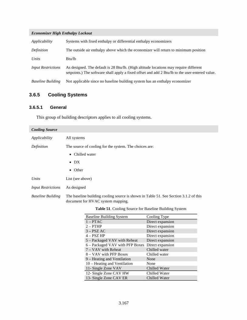
3.167
Economizer High Enthalpy Lockout
Applicability Systems with fixed enthalpy or differential enthalpy economizers
Definition The outside air enthalpy above which the economizer will return to minimum position
Units Btu/lb
Input Restrictions As designed. The default is 28 Btu/lb. (High altitude locations may require different setpoints.) The software shall apply a fixed offset and add 2 Btu/lb to the user-entered value.
Baseline Building Not applicable since no baseline building system has an enthalpy economizer
3.6.5 Cooling Systems
3.6.5.1 General
This group of building descriptors applies to all cooling systems.
Cooling Source
Applicability All systems
Definition The source of cooling for the system. The choices are:
• Chilled water
• DX
• Other
Units List (see above)
Input Restrictions As designed
Baseline Building The baseline building cooling source is shown in Table 51. See Section 3.1.2 of this document for HVAC system mapping.
Table 51. Cooling Source for Baseline Building System
Baseline Building System Cooling Type 1 – PTAC Direct expansion 2 – PTHP Direct expansion 3 – PSZ AC Direct expansion 4 – PSZ HP Direct expansion 5 – Packaged VAV with Reheat Direct expansion 6 – Packaged VAV with PFP Boxes Direct expansion 7 – VAV with Reheat Chilled water 8 – VAV with PFP Boxes Chilled water 9 – Heating and Ventilation None 10 – Heating and Ventilation None 11- Single Zone VAV Chilled Water 12- Single Zone CAV HW Chilled Water 13- Single Zone CAV ER Chilled Water
3.168
Total Cooling Capacity
Applicability All cooling systems
Definition The total cooling capacity (both sensible and latent) of a cooling coil or packaged DX system at Air-Conditioning, Heating and Refrigeration Institute (AHRI) conditions. The building descriptors defined in this chapter assume that the fan is modeled separately, including any heat it adds to the air stream. The cooling capacity specified by this building descriptor should not consider the heat of the fan.
Note that most CHW coils, and coils in custom DX equipment, particularly those serving high outside air fractions, will have capacities provided in HVAC schedules and submittals at entering air conditions very different from AHRI conditions. For these units, when entered in software using the following simulation methods, custom performance curves will generally be needed, or the capacities and efficiencies recalculated at the AHRI conditions.
Units kBtu/h
Input Restrictions As designed. For packaged equipment that has the fan motor in the air stream such that it adds heat to the cooled air, the software shall adjust the total cooling capacity as follows:
Where:
Qt,net,rated = The net total cooling capacity of a packaged unit as rated by AHRI (Btu/h)
Qt,gross,rated = The AHRI rated total cooling capacity of a packaged unit (Btu/h)
Qt,fan, rated = The heat generated by the fan and fan motor (if fan motor is in airstream) at AHRI rated conditions
If the gross and net total cooling capacities at AHRI conditions are known, the fan heat at rated conditions is the difference between the two values. If the either the gross or net total cooling capacity is unknown, the fan heat at rated conditions shall be accounted for by using equation below :
𝑊𝑊𝑓𝑓𝑌𝑌𝑚𝑚 = 𝑄𝑄𝑡𝑡.𝑔𝑔𝑌𝑌𝑔𝑔𝑔𝑔𝑔𝑔.𝑌𝑌𝑌𝑌𝑡𝑡𝑌𝑌𝑟𝑟 − 𝑄𝑄𝑡𝑡.𝑚𝑚𝑌𝑌𝑡𝑡.𝑌𝑌𝑌𝑌𝑡𝑡𝑌𝑌𝑟𝑟
3.412 [𝐵𝐵𝑃𝑃𝐵𝐵ℎ )/𝑊𝑊]
Source: Standard 90.1-2016 User’s Manual (unpublished)
ratedfanratedgrosstratednett QQQ ,,,,, −= (12)
Baseline Building The total cooling capacity of the systems in the baseline building is oversized by 15%. Sizing calculations shall be based on the heating design day and cooling design day conditions, as defined in Section 3.1.5 of this document. Oversizing would be carried out at zone level where the sizing parameters would be applied to the zone design cooling coil loads, but not the airflow rates.
3.169
Sensible Cooling Capacity
Applicability All cooling systems
Definition The sensible cooling capacity of the coil or packaged equipment at Air-conditioning and Refrigeration Institute (ARI) conditions. The building descriptors defined in this chapter assume that the fan is modeled separately, including any heat it adds to the air stream. The cooling capacity specified by this building descriptor should not consider the heat of the fan.
Note that the sensible heat ratio (SHR) used by some energy simulation tools can be calculated from the sensible cooling capacity and total cooling capacity:
SHR = Sensible Cooling Capacity / Total Cooling Capacity
Units kBtu/h
Input Restrictions As designed. For packaged equipment that has the fan motor located in the air stream such that it adds heat to the cooled air, the software shall adjust the sensible cooling capacity as follows:
545.2,, ×+= supplyratedsadjs BHPQQ (13)
Where:
Qs,adj = The adjusted sensible cooling capacity of a packaged unit (kBtu/h)
Qs,rated = The ARI rated sensible cooling capacity of a packaged unit (kBtu/h)
BHPsupply = The supply fan brake horsepower (bhp) in the proposed building design.
If the number of UMLH in the proposed design exceeds 300, the software shall warn the user to resize the equipment.
Baseline Building The sensible cooling capacity of the systems serving baseline building is oversized by 15%. Sizing calculations shall be based on the heating design day and cooling design day conditions, as defined in Section 3.1.5 of this document
Cooling Capacity Adjustment Curves
Applicability All cooling systems
Definition The sensible cooling capacity of the coil or packaged equipment at ARI conditions. The building descriptors defined in this chapter assume that the fan is modeled separately, including any heat it adds to the air stream. The cooling capacity specified by this building descriptor should not consider the heat of the fan.
Note that the SHR used by some energy simulation tools can be calculated from the sensible cooling capacity and total cooling capacity:
SHR = Sensible Cooling Capacity / Total Cooling Capacity
A curve that represents the available total cooling capacity as a function of rated cooling coil capacity and/or condenser conditions. The common form of these curves is given as follows:
adjtavailablet QFTCAPQ ,, _ ×= (14)
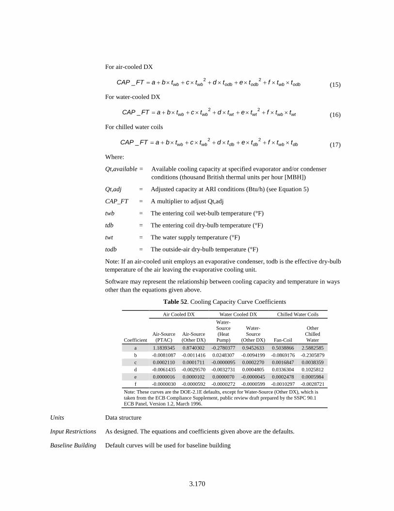
3.170
For air-cooled DX
odbwbodbodbwbwb ttftetdtctbaFTCAP ××+×+×+×+×+= 22_ (15)
For water-cooled DX
wtwbwtwtwbwb ttftetdtctbaFTCAP ××+×+×+×+×+= 22_ (16)
For chilled water coils
dbwbdbdbwbwb ttftetdtctbaFTCAP ××+×+×+×+×+= 22_ (17)
Where:
Qt,available = Available cooling capacity at specified evaporator and/or condenser conditions (thousand British thermal units per hour [MBH])
Qt,adj = Adjusted capacity at ARI conditions (Btu/h) (see Equation 5)
CAP_FT = A multiplier to adjust Qt,adj
twb = The entering coil wet-bulb temperature (°F)
tdb = The entering coil dry-bulb temperature (°F)
twt = The water supply temperature (°F)
todb = The outside-air dry-bulb temperature (°F)
Note: If an air-cooled unit employs an evaporative condenser, todb is the effective dry-bulb temperature of the air leaving the evaporative cooling unit.
Software may represent the relationship between cooling capacity and temperature in ways other than the equations given above.
Table 52. Cooling Capacity Curve Coefficients
Coefficient
Air Cooled DX Water Cooled DX Chilled Water Coils
Air-Source (PTAC)
Air-Source (Other DX)
Water-Source (Heat Pump)
Water-Source
(Other DX) Fan-Coil
Other Chilled Water
a 1.1839345 0.8740302 -0.2780377 0.9452633 0.5038866 2.5882585 b -0.0081087 -0.0011416 0.0248307 -0.0094199 -0.0869176 -0.2305879 c 0.0002110 0.0001711 -0.0000095 0.0002270 0.0016847 0.0038359 d -0.0061435 -0.0029570 -0.0032731 0.0004805 0.0336304 0.1025812 e 0.0000016 0.0000102 0.0000070 -0.0000045 0.0002478 0.0005984 f -0.0000030 -0.0000592 -0.0000272 -0.0000599 -0.0010297 -0.0028721
Note: These curves are the DOE-2.1E defaults, except for Water-Source (Other DX), which is taken from the ECB Compliance Supplement, public review draft prepared by the SSPC 90.1 ECB Panel, Version 1.2, March 1996.
Units Data structure
Input Restrictions As designed. The equations and coefficients given above are the defaults.
Baseline Building Default curves will be used for baseline building
3.171
Coil Latent Modeling Method
Applicability All DX cooling systems
Definition The method of modeling coil latent performance at part-load conditions
Units List
Input Restrictions One of the following values:
Bypass factor – used by DOE-2 based programs
NTU-effectiveness – used by EnergyPlus
Baseline Building Same as proposed
Coil Bypass Factor
Applicability All DX cooling systems (optional input)
Definition The ratio of air that bypasses the cooling coil at design conditions to the total system airflow
Units Ratio
Input Restrictions Prescribed values as shown in Table 53
Table 53. Default Coil Bypass Factors
System Type Default Bypass
Factor Packaged Terminal Air-conditioners and Heat Pumps 0.241 Other Packaged Equipment 0.190 Multi-Zone Systems 0.078 All Other 0.037
Baseline Building Defaults
Coil Bypass Factor Adjustment Curve
Applicability
All DX cooling systems (optional input)
Definition Adjustments for the amount of coil bypass due to the following factors:
• Coil airflow rate as a percentage of rated system airflow
• Entering air wet-bulb temperature
• Entering air dry-bulb temperature
• Part load ratio
Units Data structure
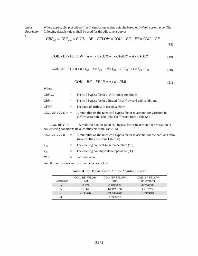
3.172
Input Restrictions
Where applicable, prescribed (fixed) simulation engine defaults based on HVAC system type. The following default values shall be used for the adjustment curves:
BFCOILFTBFCOILFFLOWBFCOILCBFCBF ratedadj −−×−−×−−×= (18)
32FFLOW-BF-COIL CFMRdCFMRcCFMRba ×+×+×+= (19)
dbwbdbdbwbwb TTfTeTdTcTba ××+×+×+×+×+= 22FT-BF-COIL (20)
PLRbaFPLRBFCOIL ×+=−− (21)
Where:
CBFrated = The coil bypass factor at ARI rating conditions
CBFadj = The coil bypass factor adjusted for airflow and coil conditions
CFMR = The ratio of airflow to design airflow
COIL-BF-FFLOW = A multiplier on the rated coil bypass factor to account for variation in airflow across the coil (take coefficients from Table 54)
COIL-BF-FT = A multiplier on the rated coil bypass factor to account for a variation in coil entering conditions (take coefficients from Table 55)
COIL-BF-FPLR = A multiplier on the rated coil bypass factor to account for the part load ratio (take coefficients from Table 56)
Twb = The entering coil wet-bulb temperature (°F)
Tdb = The entering coil dry-bulb temperature (°F)
PLR = Part load ratio
And the coefficients are listed in the tables below.
Table 54. Coil Bypass Factor Airflow Adjustment Factor
Coefficient COIL-BF-FFLOW
(PTAC) COIL-BF-FFLOW
(HP) COIL-BF-FFLOW
(PSZ/other) a -2.277 -0.8281602 -0.2542341 b 5.21140 14.3179150 1.2182558 c -1.93440 -21.8894405 0.0359784 d 9.3996897
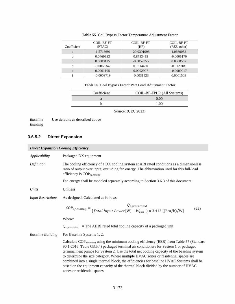
3.173
Table 55. Coil Bypass Factor Temperature Adjustment Factor
Coefficient COIL-BF-FT
(PTAC) COIL-BF-FT
(HP) COIL-BF-FT (PSZ, other)
a -1.5713691 -29.9391098 1.0660053 b 0.0469633 0.8753455 -0.0005170 c 0.0003125 -0.0057055 0.0000567 d -0.0065347 0.1614450 -0.0129181 e 0.0001105 0.0002907 -0.0000017 f -0.0003719 -0.0031523 0.0001503
Table 56. Coil Bypass Factor Part Load Adjustment Factor
Coefficient COIL-BF-FPLR (All Systems) a 0.00 b 1.00
Source: (CEC 2013)
Baseline Building
Use defaults as described above
3.6.5.2 Direct Expansion
Direct Expansion Cooling Efficiency
Applicability Packaged DX equipment
Definition The cooling efficiency of a DX cooling system at ARI rated conditions as a dimensionless ratio of output over input, excluding fan energy. The abbreviation used for this full-load efficiency is COPnf.cooling.
Fan energy shall be modeled separately according to Section 3.6.3 of this document.
Units Unitless
Input Restrictions As designed. Calculated as follows:
𝐶𝐶𝐶𝐶𝐵𝐵𝑚𝑚𝑓𝑓.𝑐𝑐𝑔𝑔𝑔𝑔𝑐𝑐𝑚𝑚𝑚𝑚𝑔𝑔 =𝑄𝑄𝑡𝑡.𝑔𝑔𝑌𝑌𝑔𝑔𝑔𝑔𝑔𝑔.𝑌𝑌𝑌𝑌𝑡𝑡𝑌𝑌𝑟𝑟
�𝑉𝑉𝑃𝑃𝑃𝑃𝑅𝑅𝐵𝐵 𝑃𝑃𝐵𝐵𝑃𝑃𝐵𝐵𝑃𝑃 𝐵𝐵𝑃𝑃𝑃𝑃𝑃𝑃𝑃𝑃[W] −𝑊𝑊𝑓𝑓𝑌𝑌𝑚𝑚 � × 3.412 [(Btu h⁄ ) W⁄ ] (22)
Where:
Qt.gross.rated = The AHRI rated total cooling capacity of a packaged unit
Baseline Building For Baseline Systems 1, 2:
Calculate COPnf.cooling using the minimum cooling efficiency (EER) from Table 57 (Standard 90.1-2016, Table G3.5.4) packaged terminal air conditioners for System 1 or packaged terminal heat pumps for System 2. Use the total net cooling capacity of the baseline system to determine the size category. Where multiple HVAC zones or residential spaces are combined into a single thermal block, the efficiencies for baseline HVAC Systems shall be based on the equipment capacity of the thermal block divided by the number of HVAC zones or residential spaces.
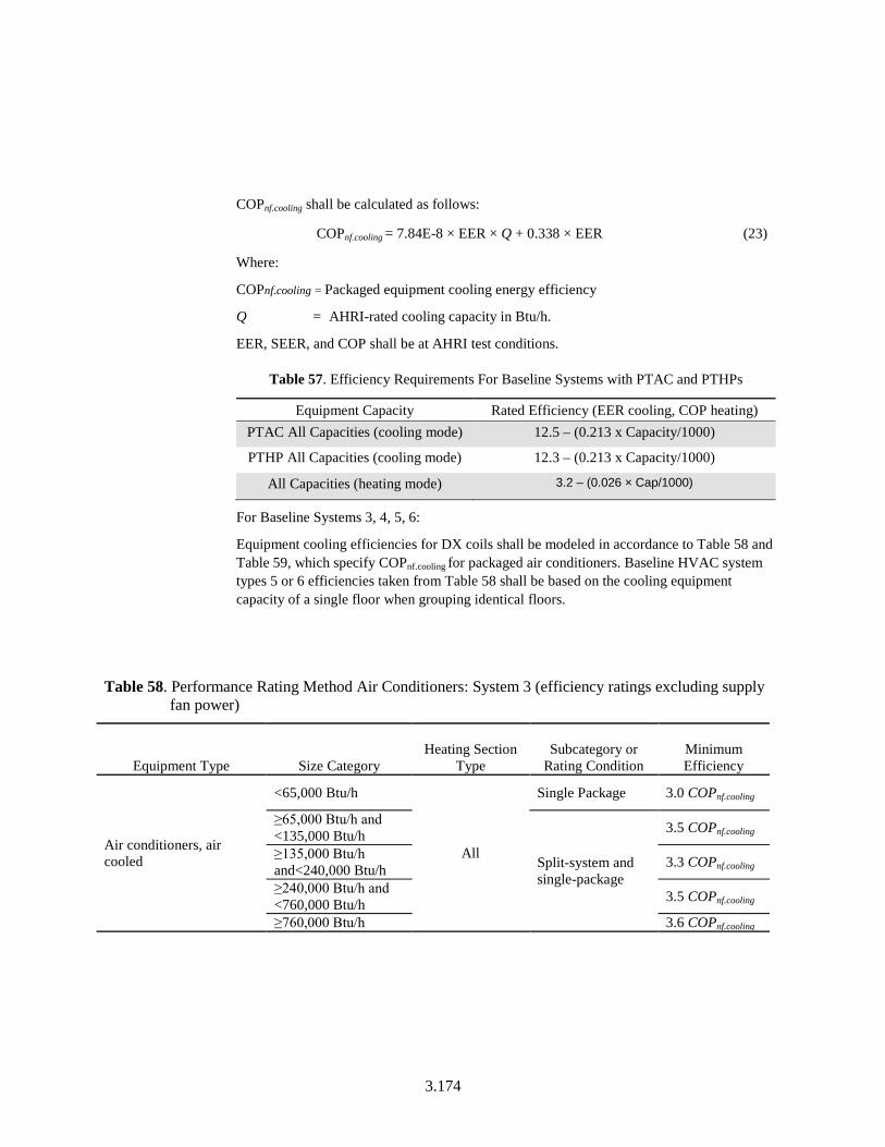
3.174
COPnf.cooling shall be calculated as follows:
COPnf.cooling = 7.84E-8 × EER × Q + 0.338 × EER (23)
Where:
COPnf.cooling = Packaged equipment cooling energy efficiency
Q = AHRI-rated cooling capacity in Btu/h.
EER, SEER, and COP shall be at AHRI test conditions.
Table 57. Efficiency Requirements For Baseline Systems with PTAC and PTHPs
Equipment Capacity Rated Efficiency (EER cooling, COP heating) PTAC All Capacities (cooling mode) 12.5 – (0.213 x Capacity/1000)
PTHP All Capacities (cooling mode) 12.3 – (0.213 x Capacity/1000)
All Capacities (heating mode) 3.2 – (0.026 × Cap/1000)
For Baseline Systems 3, 4, 5, 6:
Equipment cooling efficiencies for DX coils shall be modeled in accordance to Table 58 and Table 59, which specify COPnf.cooling for packaged air conditioners. Baseline HVAC system types 5 or 6 efficiencies taken from Table 58 shall be based on the cooling equipment capacity of a single floor when grouping identical floors.
Table 58. Performance Rating Method Air Conditioners: System 3 (efficiency ratings excluding supply fan power)
Equipment Type Size Category Heating Section
Type Subcategory or
Rating Condition Minimum Efficiency
Air conditioners, air cooled
<65,000 Btu/h
All
Single Package 3.0 COPnf.cooling
≥65,000 Btu/h and <135,000 Btu/h
Split-system and single-package
3.5 COPnf.cooling
≥135,000 Btu/h and<240,000 Btu/h 3.3 COPnf.cooling
≥240,000 Btu/h and <760,000 Btu/h 3.5 COPnf.cooling
≥760,000 Btu/h 3.6 COPnf.cooling
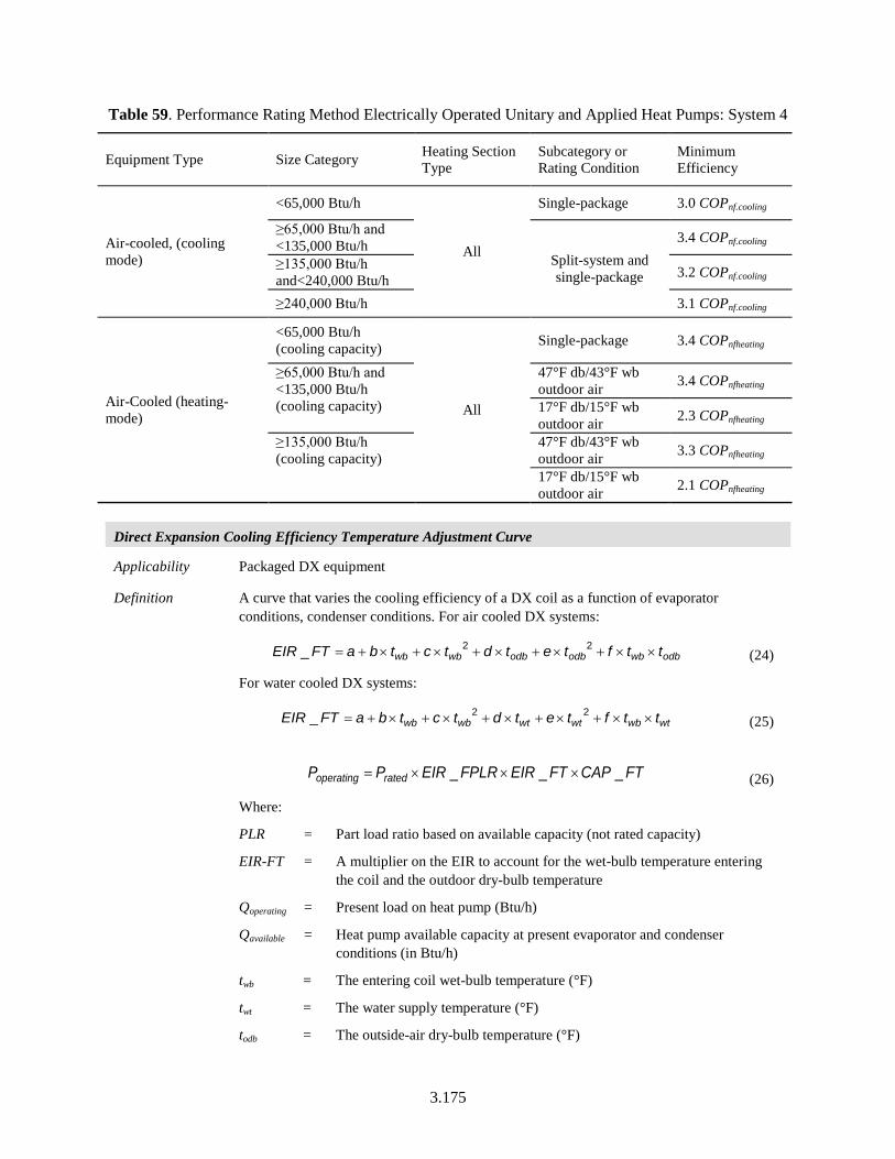
3.175
Table 59. Performance Rating Method Electrically Operated Unitary and Applied Heat Pumps: System 4
Equipment Type Size Category Heating Section Type
Subcategory or Rating Condition
Minimum Efficiency
Air-cooled, (cooling mode)
<65,000 Btu/h
All
Single-package 3.0 COPnf.cooling
≥65,000 Btu/h and <135,000 Btu/h
Split-system and single-package
3.4 COPnf.cooling
≥135,000 Btu/h and<240,000 Btu/h 3.2 COPnf.cooling
≥240,000 Btu/h 3.1 COPnf.cooling
Air-Cooled (heating-mode)
<65,000 Btu/h (cooling capacity)
All
Single-package 3.4 COPnfheating
≥65,000 Btu/h and <135,000 Btu/h (cooling capacity)
47°F db/43°F wb outdoor air 3.4 COPnfheating
17°F db/15°F wb outdoor air 2.3 COPnfheating
≥135,000 Btu/h (cooling capacity)
47°F db/43°F wb outdoor air 3.3 COPnfheating
17°F db/15°F wb outdoor air 2.1 COPnfheating
Direct Expansion Cooling Efficiency Temperature Adjustment Curve
Applicability Packaged DX equipment
Definition A curve that varies the cooling efficiency of a DX coil as a function of evaporator conditions, condenser conditions. For air cooled DX systems:
odbwbodbodbwbwb ttftetdtctbaFTEIR ××+×+×+×+×+= 22_ (24)
For water cooled DX systems:
wtwbwtwtwbwb ttftetdtctbaFTEIR ××+×+×+×+×+= 22_ (25)
FTCAPFTEIRFPLREIRPP ratedoperating ___ ×××= (26)
Where:
PLR = Part load ratio based on available capacity (not rated capacity)
EIR-FT = A multiplier on the EIR to account for the wet-bulb temperature entering the coil and the outdoor dry-bulb temperature
Qoperating = Present load on heat pump (Btu/h)
Qavailable = Heat pump available capacity at present evaporator and condenser conditions (in Btu/h)
twb = The entering coil wet-bulb temperature (°F)
twt = The water supply temperature (°F)
todb = The outside-air dry-bulb temperature (°F)
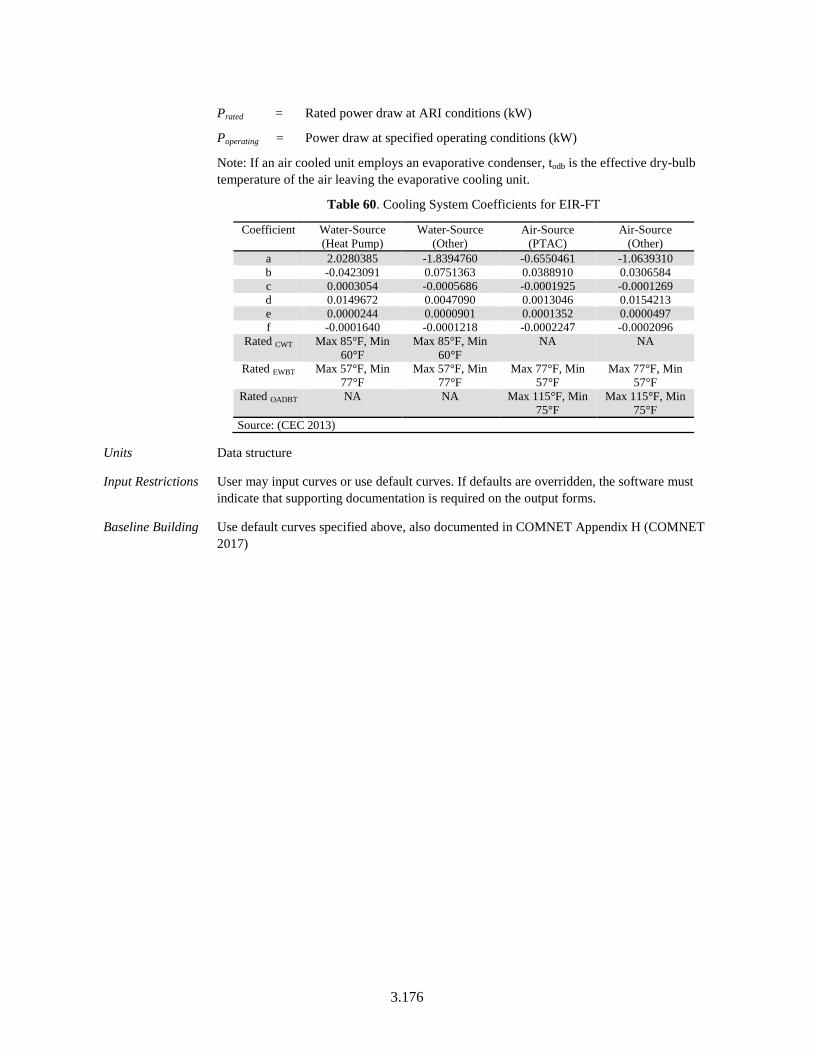
3.176
Prated = Rated power draw at ARI conditions (kW)
Poperating = Power draw at specified operating conditions (kW)
Note: If an air cooled unit employs an evaporative condenser, todb is the effective dry-bulb temperature of the air leaving the evaporative cooling unit.
Table 60. Cooling System Coefficients for EIR-FT
Coefficient Water-Source (Heat Pump)
Water-Source (Other)
Air-Source (PTAC)
Air-Source (Other)
a 2.0280385 -1.8394760 -0.6550461 -1.0639310 b -0.0423091 0.0751363 0.0388910 0.0306584 c 0.0003054 -0.0005686 -0.0001925 -0.0001269 d 0.0149672 0.0047090 0.0013046 0.0154213 e 0.0000244 0.0000901 0.0001352 0.0000497 f -0.0001640 -0.0001218 -0.0002247 -0.0002096
Rated CWT Max 85°F, Min 60°F
Max 85°F, Min 60°F
NA NA
Rated EWBT Max 57°F, Min 77°F
Max 57°F, Min 77°F
Max 77°F, Min 57°F
Max 77°F, Min 57°F
Rated OADBT NA NA Max 115°F, Min 75°F
Max 115°F, Min 75°F
Source: (CEC 2013)
Units Data structure
Input Restrictions User may input curves or use default curves. If defaults are overridden, the software must indicate that supporting documentation is required on the output forms.
Baseline Building Use default curves specified above, also documented in COMNET Appendix H (COMNET 2017)
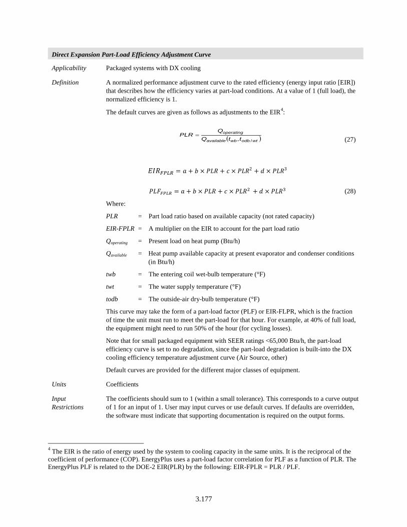
3.177
Direct Expansion Part-Load Efficiency Adjustment Curve
Applicability Packaged systems with DX cooling
Definition A normalized performance adjustment curve to the rated efficiency (energy input ratio [EIR]) that describes how the efficiency varies at part-load conditions. At a value of 1 (full load), the normalized efficiency is 1.
The default curves are given as follows as adjustments to the EIR4:
( )wtodbwbavailable
operating
ttQQ
PLR/,
= (27)
𝐸𝐸𝑃𝑃𝑅𝑅𝐹𝐹𝐹𝐹𝐹𝐹𝐹𝐹 = 𝑅𝑅 + 𝑏𝑏 × 𝐵𝐵𝑃𝑃𝑅𝑅 + 𝐸𝐸 × 𝐵𝐵𝑃𝑃𝑅𝑅2 + 𝐵𝐵 × 𝐵𝐵𝑃𝑃𝑅𝑅3
𝐵𝐵𝑃𝑃𝐵𝐵𝐹𝐹𝐹𝐹𝐹𝐹𝐹𝐹 = 𝑅𝑅 + 𝑏𝑏 × 𝐵𝐵𝑃𝑃𝑅𝑅 + 𝐸𝐸 × 𝐵𝐵𝑃𝑃𝑅𝑅2 + 𝐵𝐵 × 𝐵𝐵𝑃𝑃𝑅𝑅3 (28)
Where:
PLR = Part load ratio based on available capacity (not rated capacity)
EIR-FPLR = A multiplier on the EIR to account for the part load ratio
Qoperating = Present load on heat pump (Btu/h)
Qavailable = Heat pump available capacity at present evaporator and condenser conditions (in Btu/h)
twb = The entering coil wet-bulb temperature (°F)
twt = The water supply temperature (°F)
todb = The outside-air dry-bulb temperature (°F)
This curve may take the form of a part-load factor (PLF) or EIR-FLPR, which is the fraction of time the unit must run to meet the part-load for that hour. For example, at 40% of full load, the equipment might need to run 50% of the hour (for cycling losses).
Note that for small packaged equipment with SEER ratings <65,000 Btu/h, the part-load efficiency curve is set to no degradation, since the part-load degradation is built-into the DX cooling efficiency temperature adjustment curve (Air Source, other)
Default curves are provided for the different major classes of equipment.
Units Coefficients
Input Restrictions
The coefficients should sum to 1 (within a small tolerance). This corresponds to a curve output of 1 for an input of 1. User may input curves or use default curves. If defaults are overridden, the software must indicate that supporting documentation is required on the output forms.
4 The EIR is the ratio of energy used by the system to cooling capacity in the same units. It is the reciprocal of the coefficient of performance (COP). EnergyPlus uses a part-load factor correlation for PLF as a function of PLR. The EnergyPlus PLF is related to the DOE-2 EIR(PLR) by the following: EIR-FPLR = PLR / PLF.
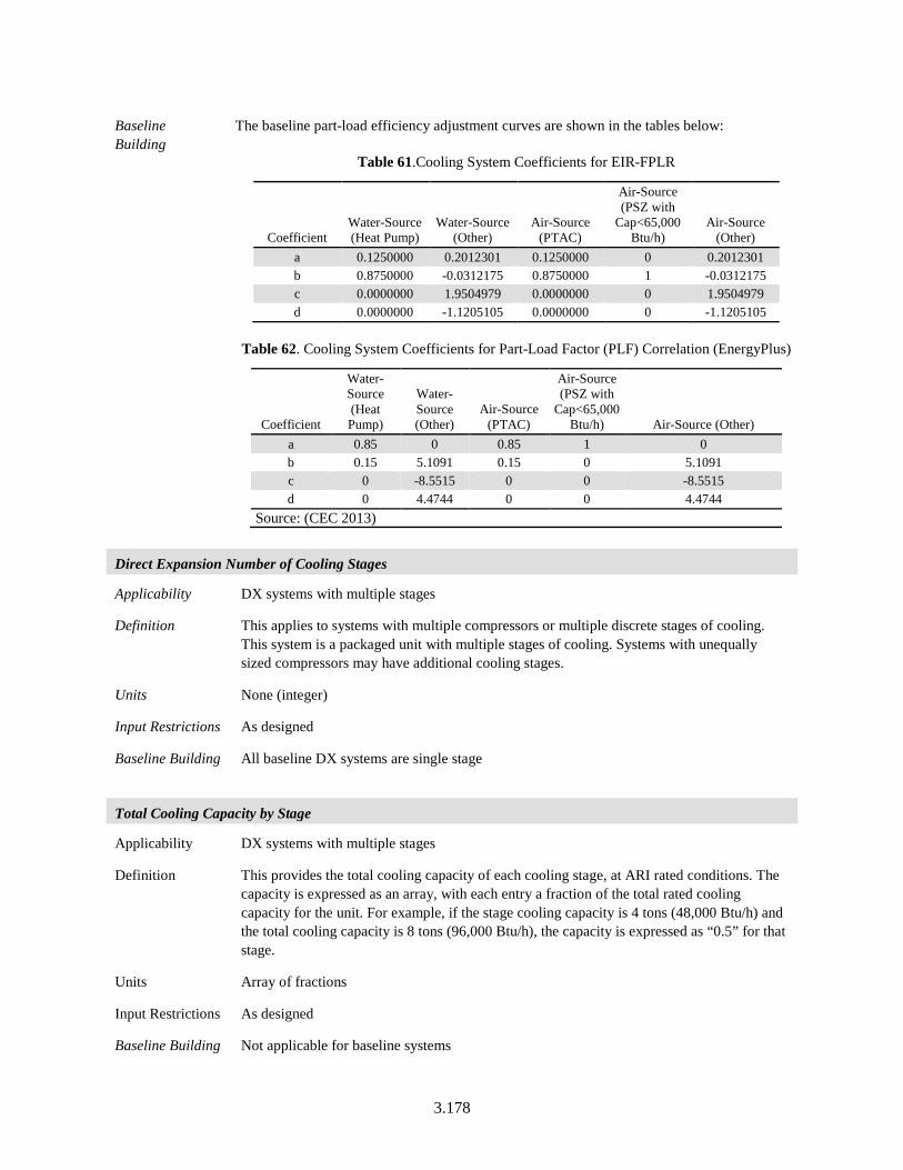
3.178
Baseline Building
The baseline part-load efficiency adjustment curves are shown in the tables below:
Table 61.Cooling System Coefficients for EIR-FPLR
Coefficient Water-Source (Heat Pump)
Water-Source (Other)
Air-Source (PTAC)
Air-Source (PSZ with
Cap<65,000 Btu/h)
Air-Source (Other)
a 0.1250000 0.2012301 0.1250000 0 0.2012301 b 0.8750000 -0.0312175 0.8750000 1 -0.0312175 c 0.0000000 1.9504979 0.0000000 0 1.9504979 d 0.0000000 -1.1205105 0.0000000 0 -1.1205105
Table 62. Cooling System Coefficients for Part-Load Factor (PLF) Correlation (EnergyPlus)
Coefficient
Water-Source (Heat Pump)
Water-Source (Other)
Air-Source (PTAC)
Air-Source (PSZ with
Cap<65,000 Btu/h) Air-Source (Other)
a 0.85 0 0.85 1 0 b 0.15 5.1091 0.15 0 5.1091 c 0 -8.5515 0 0 -8.5515 d 0 4.4744 0 0 4.4744
Source: (CEC 2013)
Direct Expansion Number of Cooling Stages
Applicability DX systems with multiple stages
Definition This applies to systems with multiple compressors or multiple discrete stages of cooling. This system is a packaged unit with multiple stages of cooling. Systems with unequally sized compressors may have additional cooling stages.
Units None (integer)
Input Restrictions As designed
Baseline Building All baseline DX systems are single stage
Total Cooling Capacity by Stage
Applicability DX systems with multiple stages
Definition This provides the total cooling capacity of each cooling stage, at ARI rated conditions. The capacity is expressed as an array, with each entry a fraction of the total rated cooling capacity for the unit. For example, if the stage cooling capacity is 4 tons (48,000 Btu/h) and the total cooling capacity is 8 tons (96,000 Btu/h), the capacity is expressed as “0.5” for that stage.
Units Array of fractions
Input Restrictions As designed
Baseline Building Not applicable for baseline systems
3.179
Sensible Cooling Capacity by Stage
Applicability DX systems with multiple stages
Definition Provides the sensible cooling capacity of each cooling stage, at ARI rated conditions. The capacity is expressed as an array, with each entry a fraction of the total rated sensible cooling capacity for the unit. For example, if the stage sensible cooling capacity is 3.5 tons (42,000 Btu/h) and the total sensible cooling capacity is 7 tons (72,000 Btu/h), the capacity is expressed as “0.5” for that stage.
Units Array of fractions
Input Restrictions As designed
Baseline Building Applicable baseline systems 1 through 6. The sensible cooling capacity of the baseline building is oversized by 15%. Sizing calculations shall be based on 1% dry-bulb and 1% wet-bulb design conditions.
Supply Fan Low Speed Ratio
Applicability Single zone DX systems with multiple stages and two-speed fans or VAV fans
Definition Specifies the low fan speed setting on a single zone VAV system or DX system with multiple cooling stages
Units None (fraction)
Input Restrictions As designed
Baseline Building Not applicable
Supply Fan Low Power Ratio
Applicability Single zone DX systems with multiple stages and two-speed fans or VAV fans
Definition Specifies the fraction of full load fan power corresponding to low fan speed operation on a single zone VAV system or DX system with multiple cooling stages
Units None (fraction)
Input Restrictions As designed
Baseline Building Not applicable
3.180
Piping Insulation
Applicability All projects
Definition Thermal insulation on piping systems for service hot water, steam piping, chilled water for cooling, and hot water for space heating
Units List (see above)
Input Restrictions Not modeled
Baseline Building Not modeled
Minimum Unloading Ratio
Applicability Packaged systems that use hot-gas bypass during low load conditions
Definition The minimum unloading ratio is where the equipment capacity can no longer be reduced by unloading and must be false loaded to meet smaller cooling loads. A typical false loading strategy is hot-gas bypass.
The minimum unloading ratio is the upper end of the hot-gas bypass operating range. This is the percentage of peak cooling capacity below the range in which hot-gas bypass will operate.
The actual unloading ratio shall be set to 50% of the user-entered minimum unloading ratio, with hot-gas-bypass operating below this level.
Units Ratio
Input Restrictions As designed. The user must enter this descriptor for each DX cooling system. If hot-gas bypass is not employed, a value of 0 may be entered.
Baseline Building Not applicable
Minimum HGB Ratio
Applicability Packaged systems that use hot-gas bypass during low load conditions
Definition The lower end of the hot-gas bypass operating range. The percentage of peak cooling capacity below which hot-gas bypass will no longer operate (i.e., the compressor will cycle).
Units Fraction (between 0 and 1)
Input Restrictions As designed. The user must enter this descriptor for each DX cooling system. If hot-gas bypass is not employed, a value of 0 may be entered.
Baseline Building Not applicable
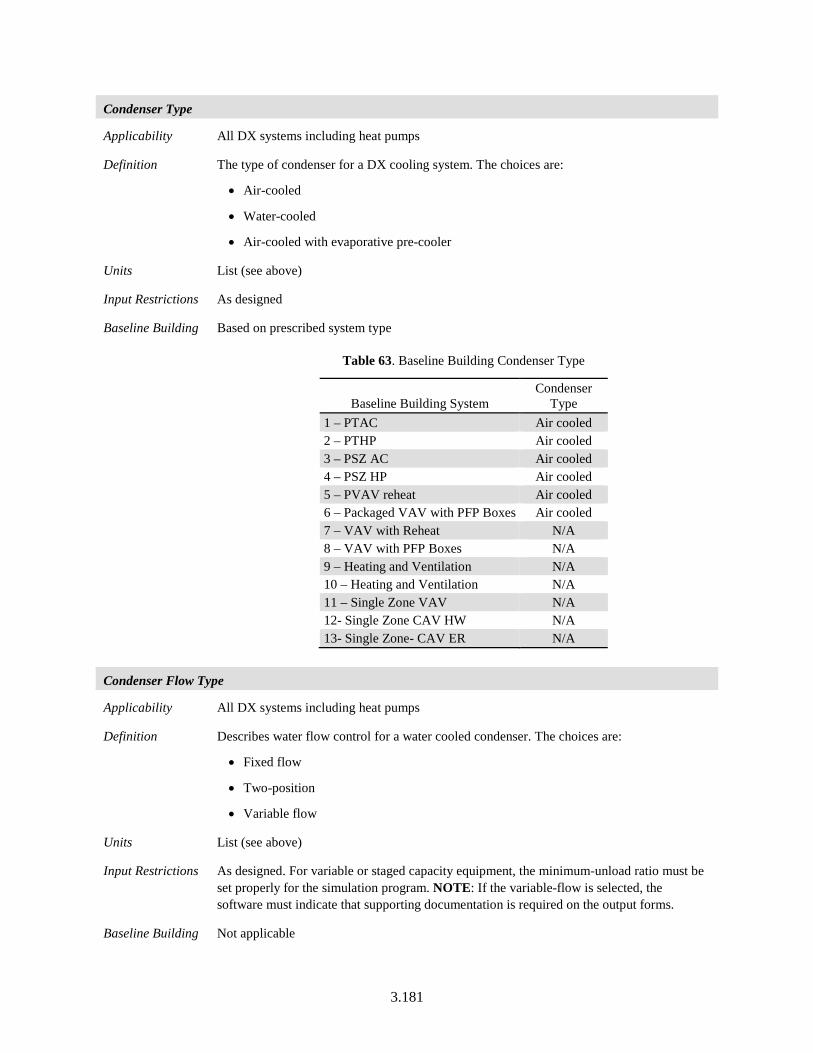
3.181
Condenser Type
Applicability All DX systems including heat pumps
Definition The type of condenser for a DX cooling system. The choices are:
• Air-cooled
• Water-cooled
• Air-cooled with evaporative pre-cooler
Units List (see above)
Input Restrictions As designed
Baseline Building Based on prescribed system type
Table 63. Baseline Building Condenser Type
Baseline Building System Condenser
Type 1 – PTAC Air cooled 2 – PTHP Air cooled 3 – PSZ AC Air cooled 4 – PSZ HP Air cooled 5 – PVAV reheat Air cooled 6 – Packaged VAV with PFP Boxes Air cooled 7 – VAV with Reheat N/A 8 – VAV with PFP Boxes N/A 9 – Heating and Ventilation N/A 10 – Heating and Ventilation N/A 11 – Single Zone VAV N/A 12- Single Zone CAV HW N/A 13- Single Zone- CAV ER N/A
Condenser Flow Type
Applicability All DX systems including heat pumps
Definition Describes water flow control for a water cooled condenser. The choices are:
• Fixed flow
• Two-position
• Variable flow
Units List (see above)
Input Restrictions As designed. For variable or staged capacity equipment, the minimum-unload ratio must be set properly for the simulation program. NOTE: If the variable-flow is selected, the software must indicate that supporting documentation is required on the output forms.
Baseline Building Not applicable
3.182
3.6.5.3 Evaporative Cooler
This is equipment that pre-cools the outside air that is brought into the building. It may be used with any type of cooling system that brings in outside air. This equipment is not applicable for the baseline building. The analyst must be careful to input evaporative cooler and outside air controls, as allowed by the software that reasonably reflect anticipated operation as indicated in sequences of operation, and review the simulation outputs, particularly zone or return air relative humidity, to ensure that the simulated sensible cooling from the evaporative cooler is realistic.
Evaporative Cooling Type
Applicability Systems with evaporative pre-cooling
Definition The type of evaporative pre-cooler, including:
• None
• Non-integrated indirect
• Non-integrated direct/indirect
• Integrated indirect
• Integrated direct/indirect
An integrated pre-cooler can operate together with the compression or CHW cooling. A non-integrated pre-cooler will shut down the evaporative cooling whenever it is unable to provide 100% of the cooling required.
In all cases, the evaporative pre-cooler must be modeled with 100% of the outside air routed through the pre-cooler.
Units None
Input Restrictions As designed
Baseline Building Not applicable
Evaporative Cooling System Capacity
Applicability Systems with evaporative cooling
Definition The total sensible cooling capacity of the evaporative cooling system at design outdoor dry-bulb conditions. This value may be derived from other inputs of supply fan design air rated capacity (5.7.3), direct stage effectiveness, indirect stage effectiveness, and design outdoor conditions.
Units None
Input Restrictions Not applicable. This is a derived input. If there are excessive UMLH in any zone served by the evaporative cooling system, a supplementary DX cooling unit must be defined by the user. See Section 3.6.5.2 of this document for descriptors related to DX cooling units.
Baseline Building Not applicable
3.183
Direct Stage Effectiveness
Applicability Systems with evaporative pre-cooling
Definition The effectiveness of the direct stage of an evaporative cooling system. Effectiveness is defined as follows:
TwbTdbTdirectTdbDirectEFF−
−=
(29)
Where:
DirectEFF = The direct stage effectiveness
Tdb = The entering air dry-bulb temperature
Twb = The entering air wet-bulb temperature
Tdirect = The direct stage leaving dry-bulb temperature
Units Numeric (0 <= eff <=1)
Input Restrictions As designed
Baseline Building Not applicable
Indirect Stage Effectiveness
Applicability Systems with evaporative pre-cooling
Definition The effectiveness of the indirect stage of an evaporative cooling system. Effectiveness is defined as follows:
TwbTdbTindTdbIndEFF
−−
= (30)
Where:
IndEFF = The indirect stage effectiveness
Tdb = The entering air dry-bulb temperature of the supply air
Twb = The entering air wet-bulb temperature of the “scavenger air”
Tind = The supply air leaving dry-bulb temperature
Units Numeric (0 <= eff <=1)
Input Restrictions As designed
Baseline Building Not applicable
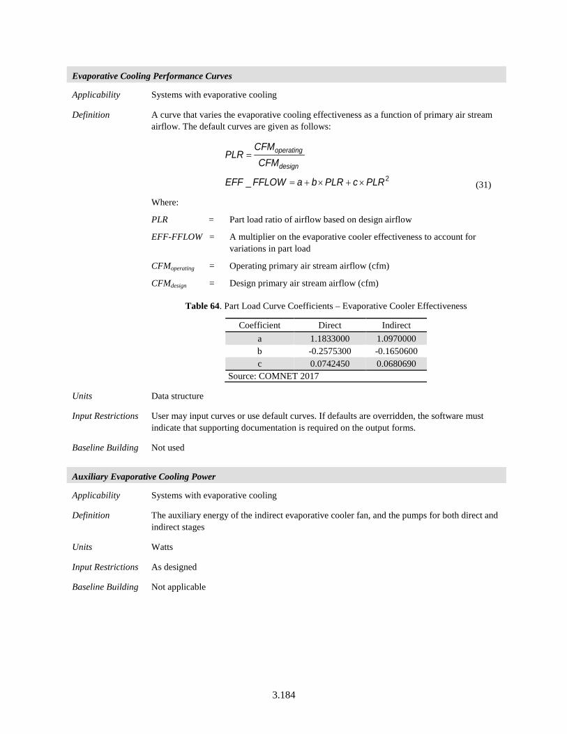
3.184
Evaporative Cooling Performance Curves
Applicability Systems with evaporative cooling
Definition A curve that varies the evaporative cooling effectiveness as a function of primary air stream airflow. The default curves are given as follows:
2_ PLRcPLRbaFFLOWEFF
CFMCFM
PLRdesign
operating
×+×+=
=
(31)
Where:
PLR = Part load ratio of airflow based on design airflow
EFF-FFLOW = A multiplier on the evaporative cooler effectiveness to account for variations in part load
CFMoperating = Operating primary air stream airflow (cfm)
CFMdesign = Design primary air stream airflow (cfm)
Table 64. Part Load Curve Coefficients – Evaporative Cooler Effectiveness
Coefficient Direct Indirect a 1.1833000 1.0970000 b -0.2575300 -0.1650600 c 0.0742450 0.0680690
Source: COMNET 2017
Units Data structure
Input Restrictions User may input curves or use default curves. If defaults are overridden, the software must indicate that supporting documentation is required on the output forms.
Baseline Building Not used
Auxiliary Evaporative Cooling Power
Applicability Systems with evaporative cooling
Definition The auxiliary energy of the indirect evaporative cooler fan, and the pumps for both direct and indirect stages
Units Watts
Input Restrictions As designed
Baseline Building Not applicable
3.185
Evaporative Cooling Scavenger Air Source
Applicability Systems with evaporative cooling
Definition The source of scavenger air for an indirect section of an evaporative cooler. Options include:
• Return air
• Outside air
Units List (see above)
Input Restrictions As designed
Baseline Building Not applicable
3.6.5.4 Evaporative Condenser
Evaporative Condenser Power
Applicability DX systems with an evaporatively cooled condenser
Definition The power of the evaporative precooling unit. This includes any pump(s) and/or fans that are part of the precooling unit.
Units Watts
Input Restrictions As designed
Baseline Building Not applicable
Evaporative Condenser Effectiveness
Applicability DX systems with an evaporatively cooled condenser
Definition The effectiveness of the evaporative precooling unit for a condenser. Effectiveness is defined as follows:
TwbTdbTdirectTdbDirectEFF−
−=
(32)
Where:
DirectEFF = The direct stage effectiveness
Tdb = The outside air dry-bulb temperature
Twb = The outside air wet-bulb temperature
Tdirect = The direct stage leaving dry-bulb temperature (at the condenser inlet)
Units Ratio
Input Restrictions As designed
Baseline Building Not applicable
3.186
Evaporative Condenser Operation Range
Applicability DX systems with an evaporatively cooled condenser
Definition The temperature range within which the evaporative condenser operates. Two values are provided:
Tmaximum = The threshold outside air dry-bulb temperature below which evaporative condenser operates.
Tminimum = The threshold outside air dry-bulb temperature above which evaporative condenser operates.
Units Degrees Fahrenheit (°F)
Input Restrictions As designed
Baseline Building Not applicable
3.6.5.5 Four-Pipe Fan Coil Systems
This section contains building descriptors required to model four-pipe fan coil systems. Note that this system requires an outside air ventilation source to serve the zones and that an airside economizer is not available. Note that additional HVAC components (chiller, boiler, pumps) are needed to fully define this system.
Capacity Control Method
Applicability Four-pipe fan coil systems
Definition The control method for the fan coil unit at the zone. The following choices are available:
• Constant fan variable flow: The fan speed is held constant to produce a fixed airflow rate whenever the unit is scheduled on. The hot water or chilled flow rate is varied so that the unit output matches the zone heating or cooling requirement.
• Constant fan constant flow: The fan speed is held constant to produce a fixed flow rate whenever the unit is scheduled on. The chilled water and hot water flow rates are kept constant at full flow.
• Cycling fan: The fan speed is chosen so that the unit capacity is greater than or equal to the heating/cooling load and the fan is cycled to match unit output with the load.
• Variable fan constant flow: The water flow rate is at full flow and the fan speed varies to meet the load.
• Variable fan variable flow: Both air and water flow rates are varied to match the load.
Units List (with choices above)
Input Restrictions Not a user input – derived from building descriptors for fan control and chiller loop flow control
Baseline Building Four pipe fan coil systems are applicable for proposed buildings with the system type defined in Table 65. The capacity control for the baseline building will be specified as “Constant Fan Constant Flow.”
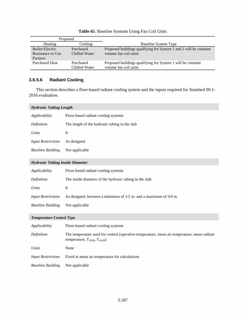
3.187
Table 65. Baseline Systems Using Fan Coil Units
Proposed Baseline System Type Heating Cooling
Boiler/Electric Resistance or Gas Furnace
Purchased Chilled Water
Proposed buildings qualifying for System 1 and 2 will be constant volume fan coil units
Purchased Heat Purchased Chilled Water
Proposed buildings qualifying for System 1 will be constant volume fan coil units
3.6.5.6 Radiant Cooling
This section describes a floor-based radiant cooling system and the inputs required for Standard 90.1-2016 evaluation.
Hydronic Tubing Length
Applicability Floor-based radiant cooling systems
Definition The length of the hydronic tubing in the slab
Units ft
Input Restrictions As designed
Baseline Building Not applicable
Hydronic Tubing Inside Diameter
Applicability Floor-based radiant cooling systems
Definition The inside diameter of the hydronic tubing in the slab
Units ft
Input Restrictions As designed, between a minimum of 1/2 in. and a maximum of 3/4 in.
Baseline Building Not applicable
Temperature Control Type
Applicability Floor-based radiant cooling systems
Definition The temperature used for control (operative temperature, mean air temperature, mean radiant temperature, TODB, TOWB)
Units None
Input Restrictions Fixed at mean air temperature for calculations
Baseline Building Not applicable
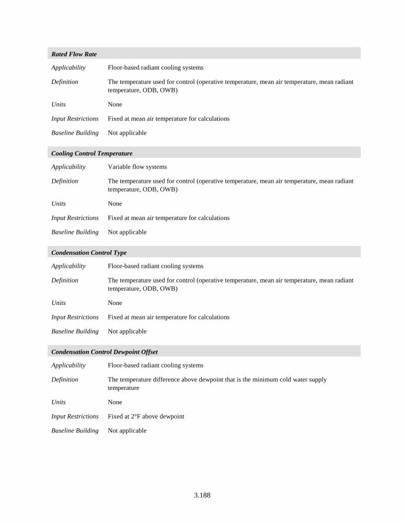
3.188
Rated Flow Rate
Applicability Floor-based radiant cooling systems
Definition The temperature used for control (operative temperature, mean air temperature, mean radiant temperature, ODB, OWB)
Units None
Input Restrictions Fixed at mean air temperature for calculations
Baseline Building Not applicable
Cooling Control Temperature
Applicability Variable flow systems
Definition The temperature used for control (operative temperature, mean air temperature, mean radiant temperature, ODB, OWB)
Units None
Input Restrictions Fixed at mean air temperature for calculations
Baseline Building Not applicable
Condensation Control Type
Applicability Floor-based radiant cooling systems
Definition The temperature used for control (operative temperature, mean air temperature, mean radiant temperature, ODB, OWB)
Units None
Input Restrictions Fixed at mean air temperature for calculations
Baseline Building Not applicable
Condensation Control Dewpoint Offset
Applicability Floor-based radiant cooling systems
Definition The temperature difference above dewpoint that is the minimum cold water supply temperature
Units None
Input Restrictions Fixed at 2°F above dewpoint
Baseline Building Not applicable
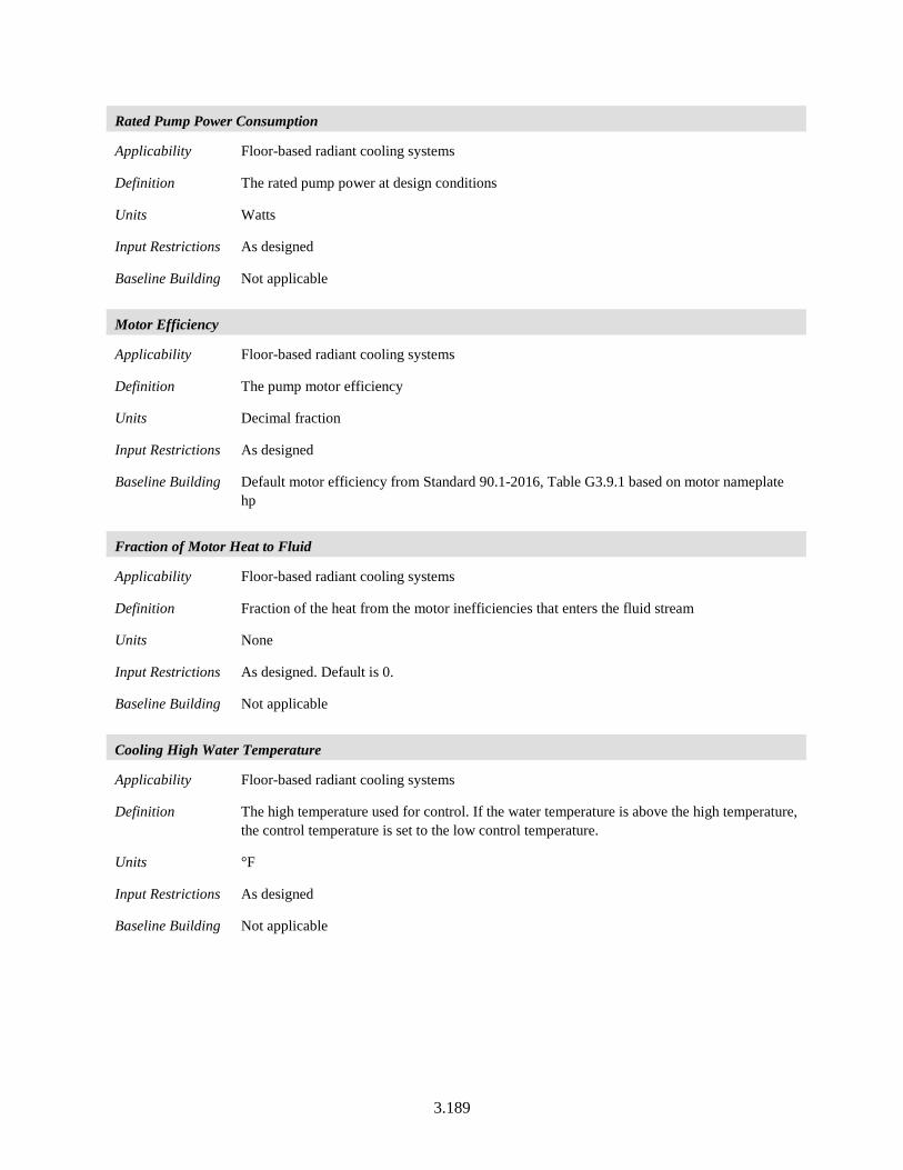
3.189
Rated Pump Power Consumption
Applicability Floor-based radiant cooling systems
Definition The rated pump power at design conditions
Units Watts
Input Restrictions As designed
Baseline Building Not applicable
Motor Efficiency
Applicability Floor-based radiant cooling systems
Definition The pump motor efficiency
Units Decimal fraction
Input Restrictions As designed
Baseline Building Default motor efficiency from Standard 90.1-2016, Table G3.9.1 based on motor nameplate hp
Fraction of Motor Heat to Fluid
Applicability Floor-based radiant cooling systems
Definition Fraction of the heat from the motor inefficiencies that enters the fluid stream
Units None
Input Restrictions As designed. Default is 0.
Baseline Building Not applicable
Cooling High Water Temperature
Applicability Floor-based radiant cooling systems
Definition The high temperature used for control. If the water temperature is above the high temperature, the control temperature is set to the low control temperature.
Units °F
Input Restrictions As designed
Baseline Building Not applicable
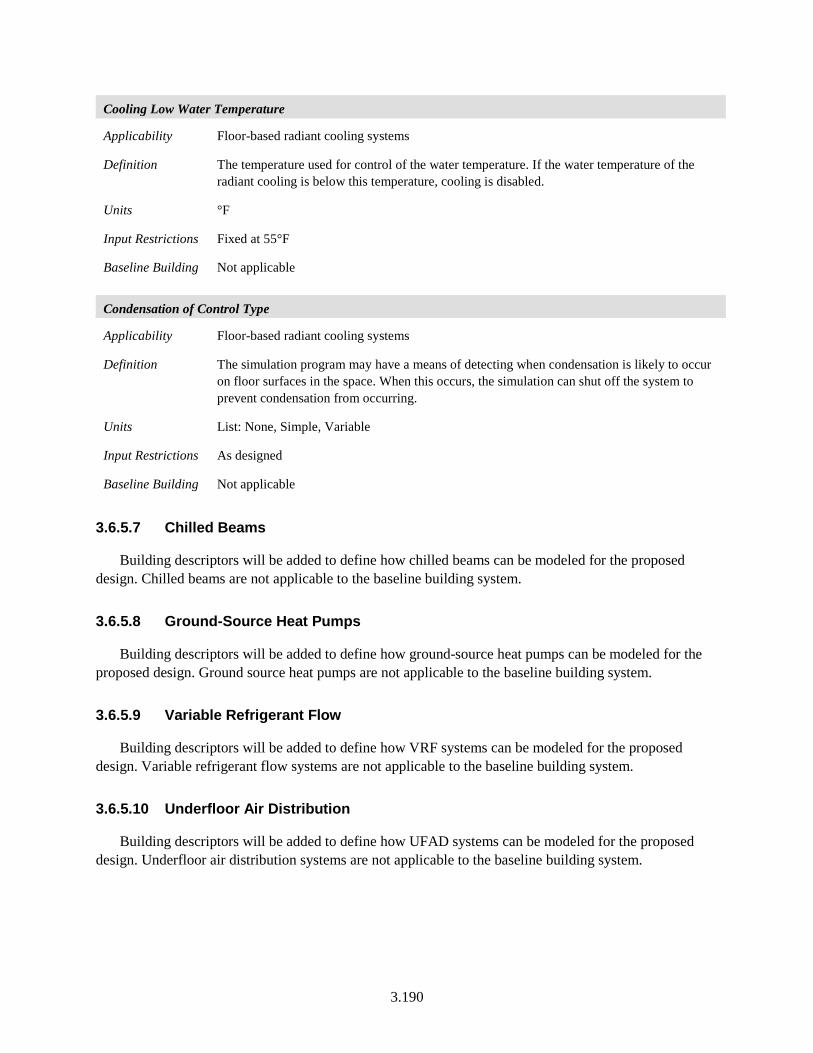
3.190
Cooling Low Water Temperature
Applicability Floor-based radiant cooling systems
Definition The temperature used for control of the water temperature. If the water temperature of the radiant cooling is below this temperature, cooling is disabled.
Units °F
Input Restrictions Fixed at 55°F
Baseline Building Not applicable
Condensation of Control Type
Applicability Floor-based radiant cooling systems
Definition The simulation program may have a means of detecting when condensation is likely to occur on floor surfaces in the space. When this occurs, the simulation can shut off the system to prevent condensation from occurring.
Units List: None, Simple, Variable
Input Restrictions As designed
Baseline Building Not applicable
3.6.5.7 Chilled Beams
Building descriptors will be added to define how chilled beams can be modeled for the proposed design. Chilled beams are not applicable to the baseline building system.
3.6.5.8 Ground-Source Heat Pumps
Building descriptors will be added to define how ground-source heat pumps can be modeled for the proposed design. Ground source heat pumps are not applicable to the baseline building system.
3.6.5.9 Variable Refrigerant Flow
Building descriptors will be added to define how VRF systems can be modeled for the proposed design. Variable refrigerant flow systems are not applicable to the baseline building system.
3.6.5.10 Underfloor Air Distribution
Building descriptors will be added to define how UFAD systems can be modeled for the proposed design. Underfloor air distribution systems are not applicable to the baseline building system.
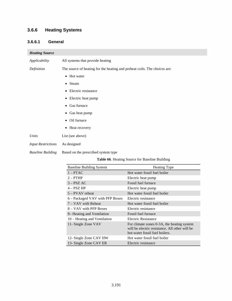
3.191
3.6.6 Heating Systems
3.6.6.1 General
Heating Source
Applicability All systems that provide heating
Definition The source of heating for the heating and preheat coils. The choices are:
• Hot water
• Steam
• Electric resistance
• Electric heat pump
• Gas furnace
• Gas heat pump
• Oil furnace
• Heat recovery
Units List (see above)
Input Restrictions As designed
Baseline Building Based on the prescribed system type
Table 66. Heating Source for Baseline Building
Baseline Building System Heating Type 1 – PTAC Hot water fossil fuel boiler 2 – PTHP Electric heat pump 3 – PSZ AC Fossil fuel furnace 4 – PSZ HP Electric heat pump 5 – PVAV reheat Hot water fossil fuel boiler 6 – Packaged VAV with PFP Boxes Electric resistance 7 – VAV with Reheat Hot water fossil fuel boiler 8 – VAV with PFP Boxes Electric resistance 9– Heating and Ventilation Fossil fuel furnace 10 – Heating and Ventilation Electric Resistance 11- Single Zone VAV
For climate zones 0-3A, the heating system will be electric resistance. All other will be hot-water fossil fuel boilers.
12- Single Zone CAV HW Hot water fossil fuel boiler 13- Single Zone CAV ER Electric resistance
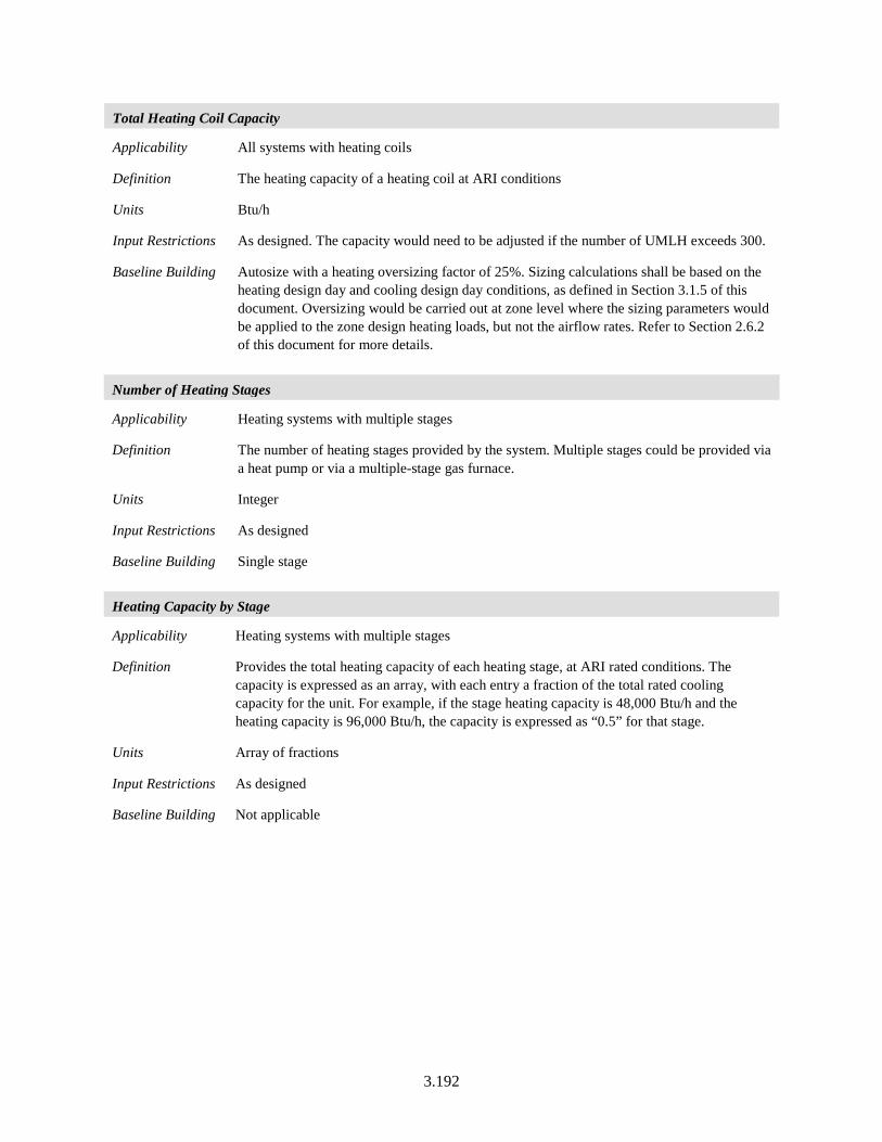
3.192
Total Heating Coil Capacity
Applicability All systems with heating coils
Definition The heating capacity of a heating coil at ARI conditions
Units Btu/h
Input Restrictions As designed. The capacity would need to be adjusted if the number of UMLH exceeds 300.
Baseline Building Autosize with a heating oversizing factor of 25%. Sizing calculations shall be based on the heating design day and cooling design day conditions, as defined in Section 3.1.5 of this document. Oversizing would be carried out at zone level where the sizing parameters would be applied to the zone design heating loads, but not the airflow rates. Refer to Section 2.6.2 of this document for more details.
Number of Heating Stages
Applicability Heating systems with multiple stages
Definition The number of heating stages provided by the system. Multiple stages could be provided via a heat pump or via a multiple-stage gas furnace.
Units Integer
Input Restrictions As designed
Baseline Building Single stage
Heating Capacity by Stage
Applicability Heating systems with multiple stages
Definition Provides the total heating capacity of each heating stage, at ARI rated conditions. The capacity is expressed as an array, with each entry a fraction of the total rated cooling capacity for the unit. For example, if the stage heating capacity is 48,000 Btu/h and the heating capacity is 96,000 Btu/h, the capacity is expressed as “0.5” for that stage.
Units Array of fractions
Input Restrictions As designed
Baseline Building Not applicable
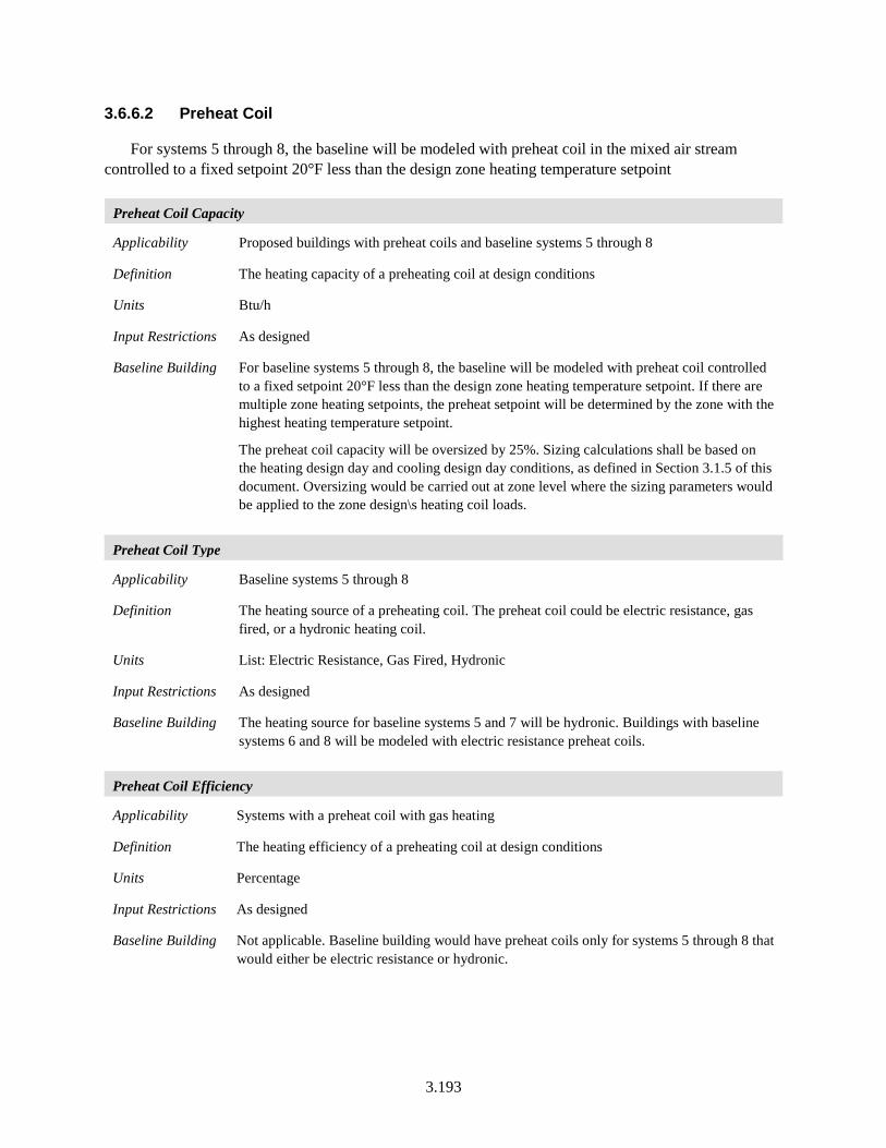
3.193
3.6.6.2 Preheat Coil
For systems 5 through 8, the baseline will be modeled with preheat coil in the mixed air stream controlled to a fixed setpoint 20°F less than the design zone heating temperature setpoint
Preheat Coil Capacity
Applicability Proposed buildings with preheat coils and baseline systems 5 through 8
Definition The heating capacity of a preheating coil at design conditions
Units Btu/h
Input Restrictions As designed
Baseline Building For baseline systems 5 through 8, the baseline will be modeled with preheat coil controlled to a fixed setpoint 20°F less than the design zone heating temperature setpoint. If there are multiple zone heating setpoints, the preheat setpoint will be determined by the zone with the highest heating temperature setpoint.
The preheat coil capacity will be oversized by 25%. Sizing calculations shall be based on the heating design day and cooling design day conditions, as defined in Section 3.1.5 of this document. Oversizing would be carried out at zone level where the sizing parameters would be applied to the zone design\s heating coil loads.
Preheat Coil Type
Applicability Baseline systems 5 through 8
Definition The heating source of a preheating coil. The preheat coil could be electric resistance, gas fired, or a hydronic heating coil.
Units List: Electric Resistance, Gas Fired, Hydronic
Input Restrictions As designed
Baseline Building The heating source for baseline systems 5 and 7 will be hydronic. Buildings with baseline systems 6 and 8 will be modeled with electric resistance preheat coils.
Preheat Coil Efficiency
Applicability Systems with a preheat coil with gas heating
Definition The heating efficiency of a preheating coil at design conditions
Units Percentage
Input Restrictions As designed
Baseline Building Not applicable. Baseline building would have preheat coils only for systems 5 through 8 that would either be electric resistance or hydronic.
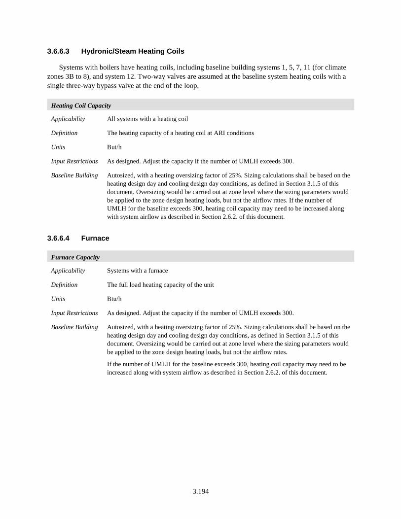
3.194
3.6.6.3 Hydronic/Steam Heating Coils
Systems with boilers have heating coils, including baseline building systems 1, 5, 7, 11 (for climate zones 3B to 8), and system 12. Two-way valves are assumed at the baseline system heating coils with a single three-way bypass valve at the end of the loop.
Heating Coil Capacity
Applicability All systems with a heating coil
Definition The heating capacity of a heating coil at ARI conditions
Units But/h
Input Restrictions As designed. Adjust the capacity if the number of UMLH exceeds 300.
Baseline Building Autosized, with a heating oversizing factor of 25%. Sizing calculations shall be based on the heating design day and cooling design day conditions, as defined in Section 3.1.5 of this document. Oversizing would be carried out at zone level where the sizing parameters would be applied to the zone design heating loads, but not the airflow rates. If the number of UMLH for the baseline exceeds 300, heating coil capacity may need to be increased along with system airflow as described in Section 2.6.2. of this document.
3.6.6.4 Furnace
Furnace Capacity
Applicability Systems with a furnace
Definition The full load heating capacity of the unit
Units Btu/h
Input Restrictions As designed. Adjust the capacity if the number of UMLH exceeds 300.
Baseline Building Autosized, with a heating oversizing factor of 25%. Sizing calculations shall be based on the heating design day and cooling design day conditions, as defined in Section 3.1.5 of this document. Oversizing would be carried out at zone level where the sizing parameters would be applied to the zone design heating loads, but not the airflow rates.
If the number of UMLH for the baseline exceeds 300, heating coil capacity may need to be increased along with system airflow as described in Section 2.6.2. of this document.
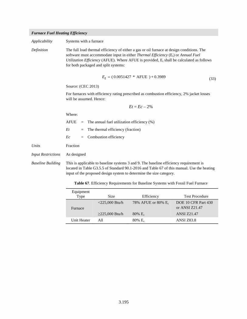
3.195
Furnace Fuel Heating Efficiency
Applicability Systems with a furnace
Definition The full load thermal efficiency of either a gas or oil furnace at design conditions. The software must accommodate input in either Thermal Efficiency (Et) or Annual Fuel Utilization Efficiency (AFUE). Where AFUE is provided, Et shall be calculated as follows for both packaged and split systems:
0.3989 + ) AFUE * 0.0051427 (=tE (33)
Source: (CEC 2013)
For furnaces with efficiency rating prescribed as combustion efficiency, 2% jacket losses will be assumed. Hence:
Et = Ec – 2%
Where:
AFUE = The annual fuel utilization efficiency (%)
Et = The thermal efficiency (fraction)
Ec = Combustion efficiency
Units Fraction
Input Restrictions As designed
Baseline Building This is applicable to baseline systems 3 and 9. The baseline efficiency requirement is located in Table G3.5.5 of Standard 90.1-2016 and Table 67 of this manual. Use the heating input of the proposed design system to determine the size category.
Table 67. Efficiency Requirements for Baseline Systems with Fossil Fuel Furnace
Equipment Type Size Efficiency Test Procedure
Furnace <225,000 Btu/h 78% AFUE or 80% Et DOE 10 CFR Part 430
or ANSI Z21.47 ≥225,000 Btu/h 80% Ec ANSI Z21.47
Unit Heater All 80% Ec ANSI Z83.8
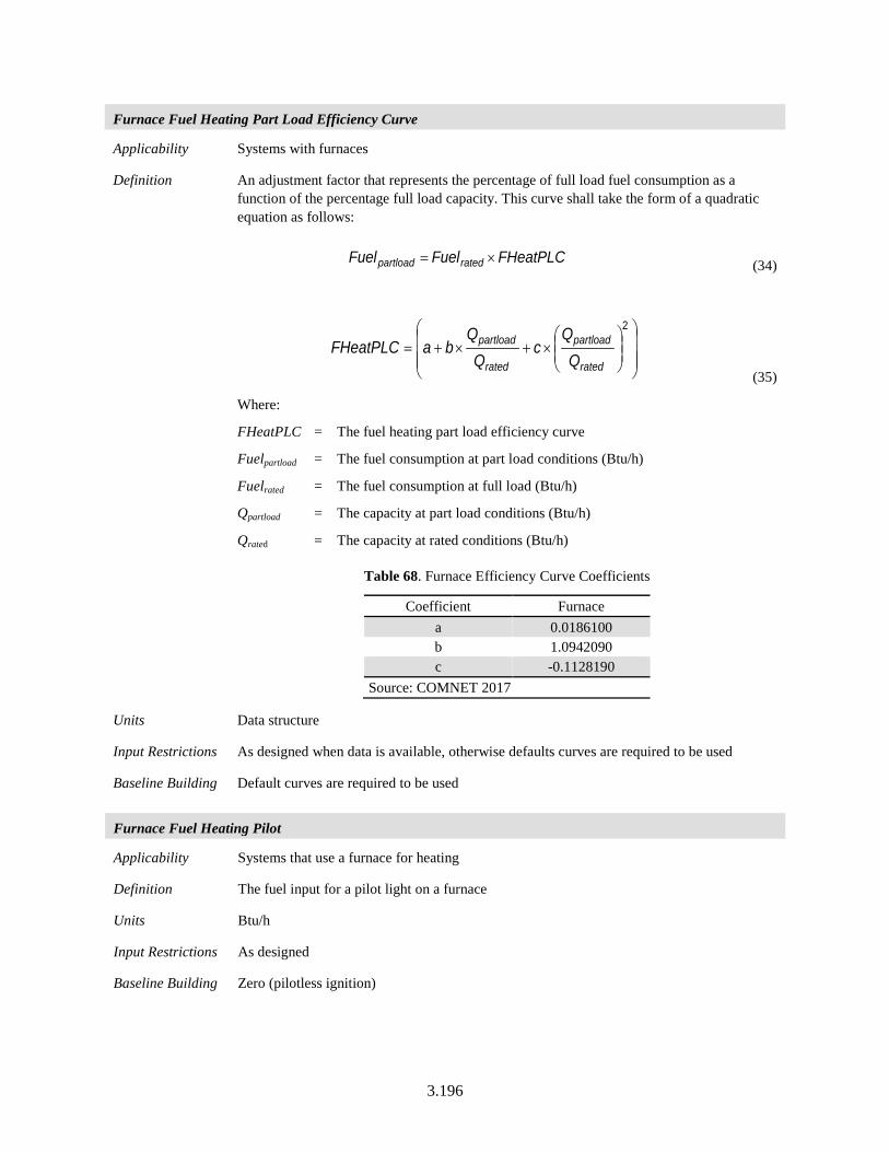
3.196
Furnace Fuel Heating Part Load Efficiency Curve
Applicability Systems with furnaces
Definition An adjustment factor that represents the percentage of full load fuel consumption as a function of the percentage full load capacity. This curve shall take the form of a quadratic equation as follows:
FHeatPLCFuelFuel ratedpartload ×= (34)
×+×+=
2
rated
partload
rated
partload
cQ
QbaFHeatPLC
(35)
Where:
FHeatPLC = The fuel heating part load efficiency curve
Fuelpartload = The fuel consumption at part load conditions (Btu/h)
Fuelrated = The fuel consumption at full load (Btu/h)
Qpartload = The capacity at part load conditions (Btu/h)
Qrated = The capacity at rated conditions (Btu/h)
Table 68. Furnace Efficiency Curve Coefficients
Coefficient Furnace a 0.0186100 b 1.0942090 c -0.1128190
Source: COMNET 2017
Units Data structure
Input Restrictions As designed when data is available, otherwise defaults curves are required to be used
Baseline Building Default curves are required to be used
Furnace Fuel Heating Pilot
Applicability Systems that use a furnace for heating
Definition The fuel input for a pilot light on a furnace
Units Btu/h
Input Restrictions As designed
Baseline Building Zero (pilotless ignition)
3.197
Furnace Fuel Heating Fan/Auxiliary Power
Applicability Systems that use a furnace for heating
Definition The fan energy in forced draft furnaces and the auxiliary (pumps and outdoor fan) energy in fuel-fired heat pumps
Units kilowatts (kW)
Input Restrictions As designed
Baseline Building Not applicable
3.6.6.5 Electric Heat Pump
Electric Heat Pump Heating Capacity
Applicability All heat pumps
Definition The full load heating capacity of the unit, excluding supplemental heating capacity at ARI rated conditions
Units Btu/h
Input Restrictions As designed
Baseline Building Autosized, with a heating oversizing factor of 25%. Sizing calculations shall be based on the heating design day and cooling design day conditions, as defined in Section 3.1.5 of this document. Oversizing would be carried out at zone level where the sizing parameters would be applied to the zone design heating loads, but not the airflow rates.
If the number of UMLH for the baseline exceeds 300, heating coil capacity may need to be increased along with system airflow as described in Section 2.6.2. of this document.
Electric Heat Pump Supplemental Heating Source
Applicability All heat pumps
Definition The auxiliary heating source for a heat pump heating system. The common control sequence is to operate the heat pump when the auxiliary heat is activated, until the low temperature limit, at which the compressor is turned off. Other building descriptors may be needed if this is not the case. Choices for supplemental heat include:
• Electric resistance • Gas furnace
• Oil furnace • Hot water
• Other
Units List (see above)
Input Restrictions As designed
Baseline Building Electric resistance
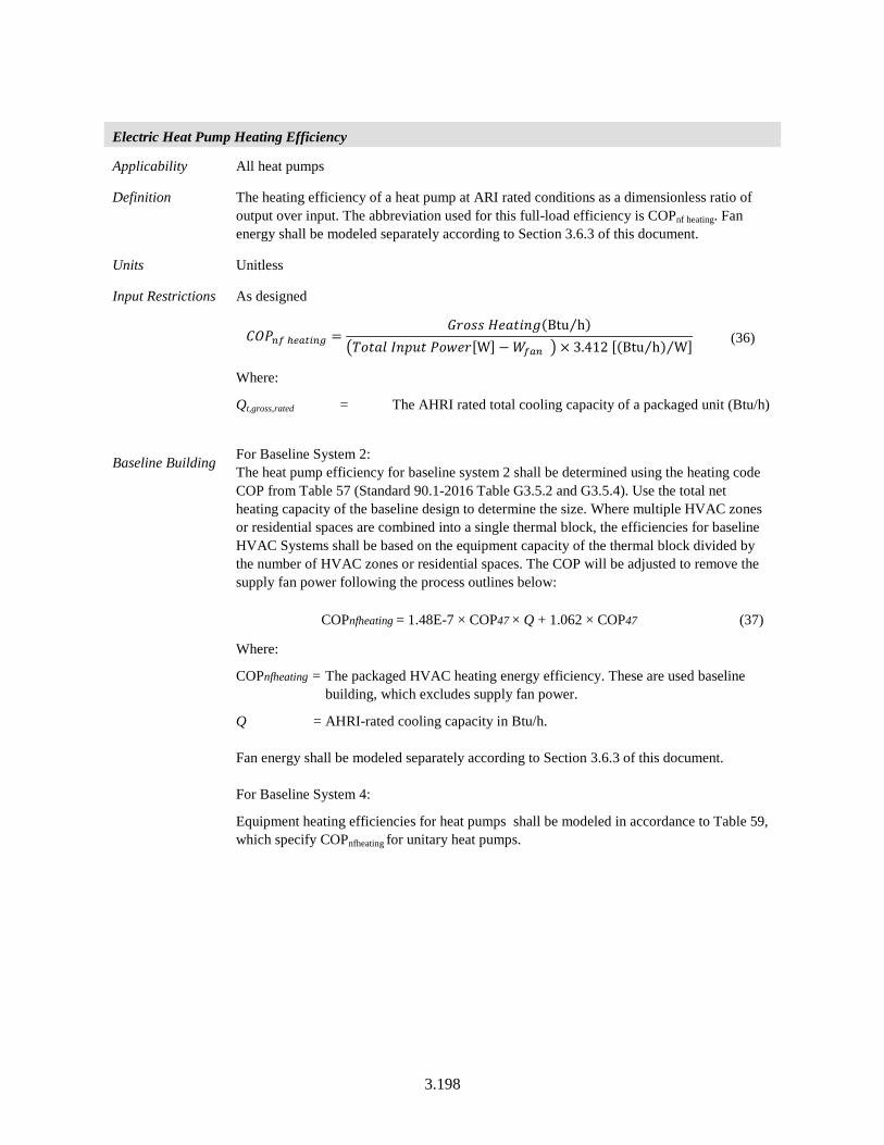
3.198
Electric Heat Pump Heating Efficiency
Applicability All heat pumps
Definition The heating efficiency of a heat pump at ARI rated conditions as a dimensionless ratio of output over input. The abbreviation used for this full-load efficiency is COPnf heating. Fan energy shall be modeled separately according to Section 3.6.3 of this document.
Units Unitless
Input Restrictions As designed
𝐶𝐶𝐶𝐶𝐵𝐵𝑚𝑚𝑓𝑓 ℎ𝑌𝑌𝑌𝑌𝑡𝑡𝑚𝑚𝑚𝑚𝑔𝑔 =𝐺𝐺𝑃𝑃𝑃𝑃𝐶𝐶𝐶𝐶 𝐻𝐻𝑃𝑃𝑅𝑅𝑃𝑃𝐵𝐵𝐵𝐵𝐵𝐵(Btu h⁄ )
�𝑉𝑉𝑃𝑃𝑃𝑃𝑅𝑅𝐵𝐵 𝑃𝑃𝐵𝐵𝑃𝑃𝐵𝐵𝑃𝑃 𝐵𝐵𝑃𝑃𝑃𝑃𝑃𝑃𝑃𝑃[W] −𝑊𝑊𝑓𝑓𝑌𝑌𝑚𝑚 � × 3.412 [(Btu h⁄ ) W⁄ ] (36)
Where:
Qt,gross,rated = The AHRI rated total cooling capacity of a packaged unit (Btu/h)
Baseline Building For Baseline System 2: The heat pump efficiency for baseline system 2 shall be determined using the heating code COP from Table 57 (Standard 90.1-2016 Table G3.5.2 and G3.5.4). Use the total net heating capacity of the baseline design to determine the size. Where multiple HVAC zones or residential spaces are combined into a single thermal block, the efficiencies for baseline HVAC Systems shall be based on the equipment capacity of the thermal block divided by the number of HVAC zones or residential spaces. The COP will be adjusted to remove the supply fan power following the process outlines below:
COPnfheating = 1.48E-7 × COP47 × Q + 1.062 × COP47 (37)
Where:
COPnfheating = The packaged HVAC heating energy efficiency. These are used baseline building, which excludes supply fan power.
Q = AHRI-rated cooling capacity in Btu/h. Fan energy shall be modeled separately according to Section 3.6.3 of this document. For Baseline System 4:
Equipment heating efficiencies for heat pumps shall be modeled in accordance to Table 59, which specify COPnfheating for unitary heat pumps.
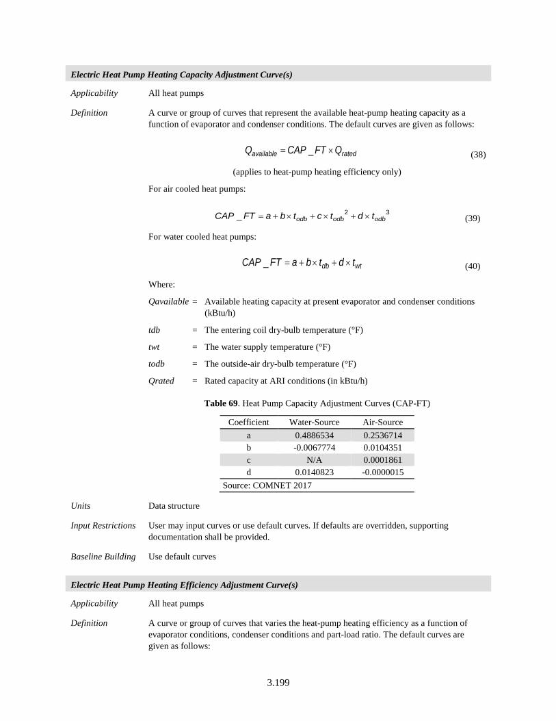
3.199
Electric Heat Pump Heating Capacity Adjustment Curve(s)
Applicability All heat pumps
Definition A curve or group of curves that represent the available heat-pump heating capacity as a function of evaporator and condenser conditions. The default curves are given as follows:
ratedavailable QFTCAPQ ×= _ (38)
(applies to heat-pump heating efficiency only)
For air cooled heat pumps:
32_ odbodbodb tdtctbaFTCAP ×+×+×+= (39)
For water cooled heat pumps:
wtdb tdtbaFTCAP ×+×+=_ (40)
Where:
Qavailable = Available heating capacity at present evaporator and condenser conditions (kBtu/h)
tdb = The entering coil dry-bulb temperature (°F)
twt = The water supply temperature (°F)
todb = The outside-air dry-bulb temperature (°F)
Qrated = Rated capacity at ARI conditions (in kBtu/h)
Table 69. Heat Pump Capacity Adjustment Curves (CAP-FT)
Coefficient Water-Source Air-Source a 0.4886534 0.2536714 b -0.0067774 0.0104351 c N/A 0.0001861 d 0.0140823 -0.0000015
Source: COMNET 2017
Units Data structure
Input Restrictions User may input curves or use default curves. If defaults are overridden, supporting documentation shall be provided.
Baseline Building Use default curves
Electric Heat Pump Heating Efficiency Adjustment Curve(s)
Applicability All heat pumps
Definition A curve or group of curves that varies the heat-pump heating efficiency as a function of evaporator conditions, condenser conditions and part-load ratio. The default curves are given as follows:
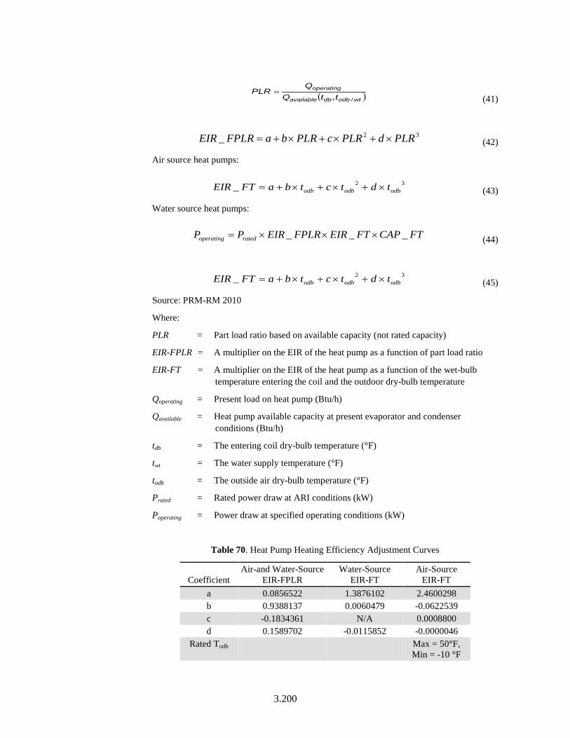
3.200
( )wtodbdbavailable
operating
ttQQ
PLR/,
= (41)
32_ PLRdPLRcPLRbaFPLREIR ×+×+×+= (42)
Air source heat pumps:
32_ odbodbodb tdtctbaFTEIR ×+×+×+= (43)
Water source heat pumps:
FTCAPFTEIRFPLREIRPP ratedoperating ___ ×××= (44)
32_ odbodbodb tdtctbaFTEIR ×+×+×+= (45)
Source: PRM-RM 2010
Where:
PLR = Part load ratio based on available capacity (not rated capacity)
EIR-FPLR = A multiplier on the EIR of the heat pump as a function of part load ratio
EIR-FT = A multiplier on the EIR of the heat pump as a function of the wet-bulb temperature entering the coil and the outdoor dry-bulb temperature
Qoperating = Present load on heat pump (Btu/h)
Qavailable = Heat pump available capacity at present evaporator and condenser conditions (Btu/h)
tdb = The entering coil dry-bulb temperature (°F)
twt = The water supply temperature (°F)
todb = The outside air dry-bulb temperature (°F)
Prated = Rated power draw at ARI conditions (kW)
Poperating = Power draw at specified operating conditions (kW)
Table 70. Heat Pump Heating Efficiency Adjustment Curves
Coefficient Air-and Water-Source
EIR-FPLR Water-Source
EIR-FT Air-Source
EIR-FT a 0.0856522 1.3876102 2.4600298 b 0.9388137 0.0060479 -0.0622539 c -0.1834361 N/A 0.0008800 d 0.1589702 -0.0115852 -0.0000046
Rated Todb Max = 50°F, Min = -10 °F
3.201
Rated Twt NA Source: CEC 2013
Units None
Input Restrictions User may input curves or use default curves. If defaults are overridden, documentation shall be provided.
Baseline Building Use default curves
Electric Heat Pump Supplemental Heating Capacity
Applicability All heat pumps
Definition The design heating capacity of a heat pump supplemental heating coil at ARI conditions
Units Btu/h
Input Restrictions As designed
Baseline Building Autosize
Electric Supplemental Heating Control Temp
Applicability All heat pumps
Definition The outside dry-bulb temperature below which the heat pump supplemental heating is allowed to operate
Units Degrees Fahrenheit (°F)
Input Restrictions As designed. Default to 40°F.
Baseline Building The space is required to be controlled with multistage space thermostats and an outdoor air thermostat that would energize the auxiliary heat on the last thermostat stage and when the OAT is less than 40°F. The air-source heat pump shall be modeled to continue to operate when auxiliary heat is energized below 40°F.
Heat Pump Compressor Minimum Operating Temp
Applicability All heat pumps
Definition The outside dry-bulb temperature below which the heat pump compressor is disabled
Units Degrees Fahrenheit (°F)
Input Restrictions As designed. Default to 35°F.
Baseline Building For baseline system 4, the compressor minimum operating temperature is 0°F, and for system 2 it is 35°F
3.202
Coil Defrost
Applicability Air cooled electric heat pump
Definition The defrost control mechanism for an air cooled heat pump. The choices are:
• Hot-gas defrost, on-demand
• Hot-gas defrost, timed 3.5 minute cycle
• Electric resistance defrost, on-demand
• Electric resistance defrost, timed 3.5 minute cycle
Defrost shall be enabled whenever the outside air dry-bulb temperature drops below 40°F.
Units List (see above)
Input Restrictions Default to use hot-gas defrost, timed 3.5 minute cycle. User may select any of the above.
Baseline Building The baseline building uses the default
Coil Defrost kW
Applicability Heat pumps with electric resistance defrost
Definition The capacity of the electric resistance defrost heater
Units kilowatts (kW)
Input Restrictions As designed. This descriptor defaults to 0 if nothing is entered.
Baseline Building Not applicable
Crank Case Heater kW
Applicability All heat pumps
Definition The capacity of the electric resistance heater in the crank case of a DX compressor. The crank case heater operates only when the compressor is off.
Units kilowatts (kW)
Input Restrictions As designed. This descriptor defaults to 0 if nothing is entered.
Baseline Building Zero (0)
3.203
Crank Case Heater Shutoff Temperature
Applicability All heat pumps
Definition The outdoor air dry-bulb temperature above which the crank case heater is not permitted to operate
Units Degrees Fahrenheit (°F)
Input Restrictions As designed. This descriptor defaults to 50°F.
Baseline Building 50°F
3.6.6.6 Energy Recovery
For baseline systems requiring energy recovery, the heat exchanger is assumed to be integral with the AHU. The system fan power or pressure drop will be adjusted according to the methods in Section 3.6.3.1 of this document.
For proposed systems with heat recovery, the analyst must be careful to set all descriptors, particularly those for control, parasitic energy, and exhaust airflows, to realistically represent the equipment components, operation, and maintenance of building pressurization.
When exhaust air energy recovery systems are installed in cold climates, frost control may significantly affect total recovered energy during subfreezing conditions. Pumps and dedicated fans will consume parasitic energy. Simulation program inputs and hourly reports should be reviewed to ensure all items are represented as close as possible to the actual result of the proposed control sequences.
Requirements related to condenser heat recovery are documented in Section 3.7.7 of this manual.
Exhaust Air Energy Recovery
Applicability Any system with outside air heat recovery
Definition Provision of exhaust air energy recovery system. Provisions shall be made to bypass heat recovery system to permit air-side economizer operation as specified in Section 3.6.4.2 of this document.
Units Unitless
Input Restrictions As designed
Baseline Building Required for fan systems with a design supply air flow rate of 5,000 cfm or greater, if the minimum outside air quantity is 70% of the design air flow rate. Energy recovery is not required for the following situations:
• Systems serving spaces that are not cooled and that are heated to less than 60°F.
• Systems exhausting toxic, flammable, paint, or corrosive fumes or dust. This exception shall only be used if heat recovery is not used in the proposed design.
3.204
• Commercial kitchen hoods used for collecting and removing grease vapors and smoke classified as Type 1 my NFPA 96. This exception shall only be used if heat recovery is not used in the proposed design.
• Heating systems in climate zones 1 through 3
• Cooling systems in climate zones 3c, 4c, 5b, 5c, 6b, 7 and 8
• Where the largest source of air exhausted at a single location at the building exterior is less than 75% of the design outdoor air flow rate. This exception shall only be used if heat recovery is not used in the proposed design.
• Systems requiring dehumidification that employ energy recovery in series with the cooling coil. This exception shall only be used if heat recovery is not used in the proposed design.
Enthalpy Recovery Ratio
Applicability Any system with outside air heat recovery
Definition The effectiveness of an air-to-air heat exchanger between the building exhaust and entering outside air streams. Effectiveness is defined as follows:
( )( )OSAHEEAH
ELAHEEAHHREFF−−
= (46)
Where:
HREFF = The air-to-air heat exchanger effectiveness
EEAH = The total enthalpy of the exhaust air entering the heat exchanger
ELAH = The total enthalpy of the exhaust air leaving the heat exchanger
OSAH = The total enthalpy of the outside air
Units Fraction (between 0 and 1)
Input Restrictions As designed in accordance to the formula above
Baseline Building The baseline would have 50% energy recovery effectiveness based on design conditions. Fifty percent energy recovery effectiveness shall mean a change in the enthalpy of the outdoor air supply equal to 50% of the difference between the outdoor air and return air enthalpies at design conditions.
3.205
Exhaust Air Energy Recovery Economizer Interaction
Applicability Any system with outside air enthalpy heat recovery
Definition Energy recovery control during economizer operation
Units Lockout, no lockout
Input Restrictions As designed
Baseline Building Lockout. The baseline system should bypass the energy recovery device during economizer operation. Refer to Section 3.6.4 of this document for baseline economizer requirements. During economizer operation, parasitic losses of energy recovery device and fan energy impact of pressure drop through energy recovery device should not occur.
Heat Exchanger Parasitic Energy
Applicability Systems that use heat recovery
Definition This input is used to model electric power consumption by controls (transformers, relays, etc.) and/or a motor for a rotary heat exchanger. None of this electric power contributes thermal load to the supply or exhaust air streams.
Units Watts (W)
Input Restrictions As designed. A default of 50W is assumed which can be overridden by the user.
Baseline Building 50W
Heat Exchanger Fan Energy Consumption
Applicability Systems that use heat recovery
Definition The additional fan energy needed for the energy recovery device.
For all energy recovery ventilator (ERV) systems that include a bypass during economizer operations, the fan energy consumption for ERV systems should only be modeled when the ERV runs and should not be considered when the ERV is bypassed for economizer operation.
Units Watts (W)
Input Restrictions As designed
Baseline Building The ERV fan power for the baseline system can be calculated as follows:
Bhp = [ (0.6 × OAcfm) + (0.6 × 0.9 × OAcfm)] /4131
W = bhp x 746/nm
This has been calculated from:
Bhp = [((2.2 × HREFF) - dpoa) × OAcfm]/4131 + [ ((2.2 × HREFF × Ef ) – dpex) × OAcfm ]/4131
Where:
3.206
Bhp = Fan brake horse power
HREFF = Heat exchanger effectiveness
dpoa = ERV pressure drop on the outdoor air side (is assumed to be 0.5 in. w.c.)
dpex = ERV pressure drop on the exhaust air side (is assumed to be 0.5 in. w.c.)
Ef = Exhaust airflow fraction (exhaust airflow is 90% of outdoor airflow after considering leakage and zone exhaust)
W = Fan power
nm = Fan motor efficiency of supply fan. For EnergyPlus fan, energy for an ERV is not an input of the ERV module and the ERV fan energy should not simply be added to the system supply fan if the ERV includes a bypass during economizer operations as required in the baseline. The following workaround should be used instead. The fan energy associated with energy recovery is modeled as additional ERV parasitic power. This results in the ERV fan energy occurring only when the ERV runs, which is the desired behavior. If there is not a bypass in the proposed design, ERV fan energy shall be included in the HVAC system fan so that its impact is accounted for whenever the fans are running.
3.6.7 Humidity Controls and Devices
Humidity control, devices, and sources are not represented fully in many simulation program, but humidification and dehumidification can result in significant energy consumption. A simulation program should be chosen that most adequately represents the components, or has adequate workarounds implemented, or supplemental calculations employed to determine the associated energy use. These methods should be documented in the manner required for “exceptional calculations.”
3.6.7.1 General
Humidifier Type
Applicability Optional humidifier
Definition The type of humidifier employed. Choices include:
• Hot water
• Steam
• Electric
• Evaporative humidification
• Adiabatic humidification
Units List (see above)
Input Restrictions As designed
Baseline Building For systems serving zones where humidification is included in the proposed design, the
3.207
baseline shall include the same humidifier type unless the proposed humidifier does not include automatic shutoff valves and insulated dispersion tubes meeting the requirements of 90.1-2016 Section 6.5.2.4. In that case, adiabatic humidification shall be used in the baseline. In either case, the baseline humidification system uses the same schedule and setpoints as the proposed building.
Humidistat Maximum Setting
Applicability Systems with humidity control
Definition The control setpoint for dehumidification
Units Percent (%)
Input Restrictions As designed
Baseline Building If the proposed design HVAC system(s) have humidistatic controls, then the baseline building design shall use mechanical cooling for dehumidification and shall have reheat available to avoid overcooling. Systems serving computer rooms shall not have reheat for dehumidification. The reheat type shall be the same as the system heating type. Only 25% of the system reheat energy shall be included in the baseline building performance, when the baseline building doesn’t comply with any of the exceptions listed below (Standard 90.1-2016 Section 6.5.2.3). The requirements and exceptions to the same are listed below-
Humidity controls shall prevent reheating, mixing of hot and cold airstreams, or other means of simultaneous heating and cooling of the same airstream.
Exceptions :
1. The system is capable of and configured to reduce supply air volume to 50% or less of the design airflow rate or the minimum outdoor air ventilation rate specified in ASHRAE Standard 62.1 or other applicable federal, state, or local code or recognized standard, whichever is larger, before simultaneous heating and cooling takes place.
2. The individual fan cooling unit has a design cooling capacity of 65,000 Btu/h or less and is capable of and configured to unload to 50% capacity before simultaneous heating and cooling takes place.
3. The individual mechanical cooling unit has a design cooling capacity of 40,000 Btu/h or less. An individual mechanical cooling unit is a single system comprising a fan or fans and a cooling coil capable of providing mechanical cooling.
4. Systems serving spaces where specific humidity levels are required to satisfy process needs, such as vivariums; museums; surgical suites; pharmacies; and buildings with refrigerating systems, such as supermarkets, refrigerated warehouses, and ice arenas, and where the building includes site-recovered energy or site-solar energy that provide energy equal to at least 75% of the annual energy for reheating or for providing warm air in mixing systems. This exception does not apply to computer rooms.
5. At least 90% of the annual energy for reheating or for providing warm air in mixing systems is provided from site-recovered energy (including condenser heat) or site-solar energy.
6. Systems where the heat added to the airstream is the result of the use of a desiccant
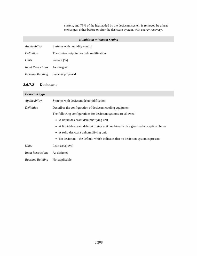
3.208
system, and 75% of the heat added by the desiccant system is removed by a heat exchanger, either before or after the desiccant system, with energy recovery.
Humidistat Minimum Setting
Applicability Systems with humidity control
Definition The control setpoint for dehumidification
Units Percent (%)
Input Restrictions As designed
Baseline Building Same as proposed
3.6.7.2 Desiccant
Desiccant Type
Applicability Systems with desiccant dehumidification
Definition Describes the configuration of desiccant cooling equipment
The following configurations for desiccant systems are allowed:
• A liquid desiccant dehumidifying unit
• A liquid desiccant dehumidifying unit combined with a gas-fired absorption chiller
• A solid desiccant dehumidifying unit
• No desiccant – the default, which indicates that no desiccant system is present
Units List (see above)
Input Restrictions As designed
Baseline Building Not applicable
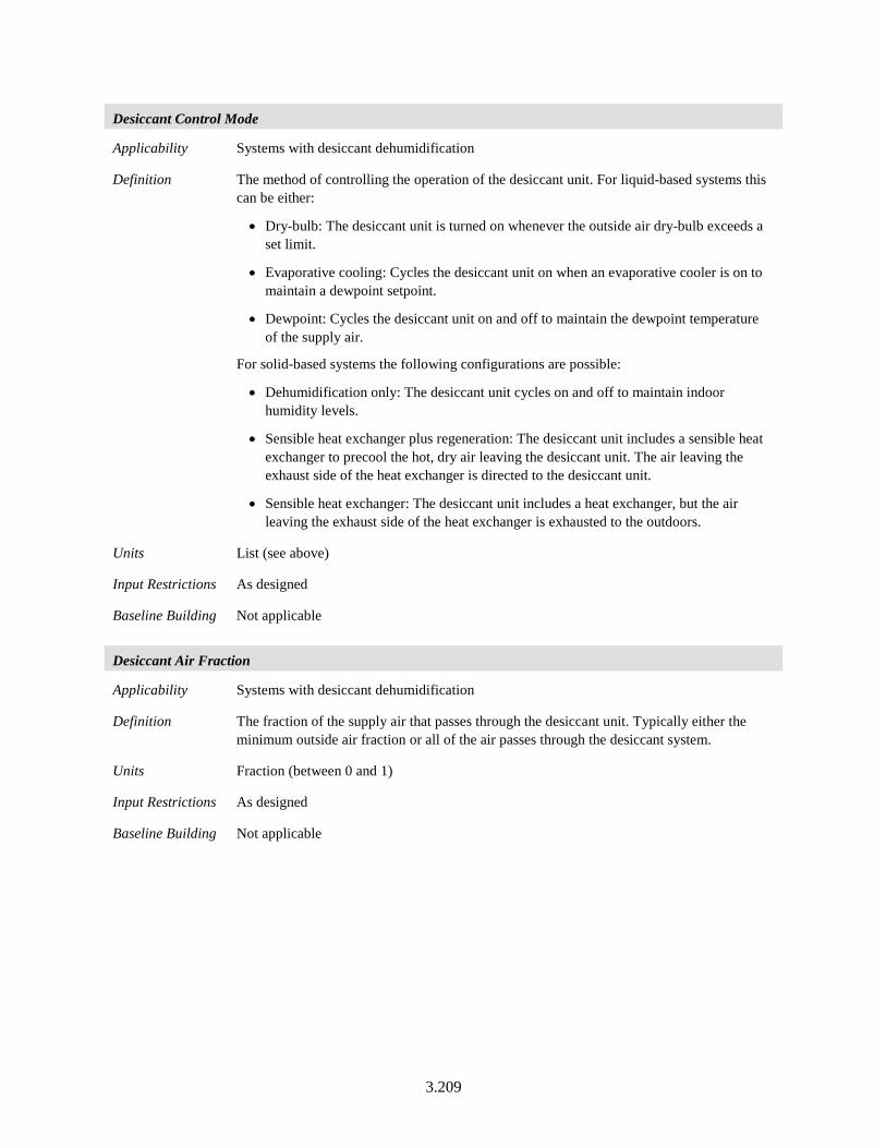
3.209
Desiccant Control Mode
Applicability Systems with desiccant dehumidification
Definition The method of controlling the operation of the desiccant unit. For liquid-based systems this can be either:
• Dry-bulb: The desiccant unit is turned on whenever the outside air dry-bulb exceeds a set limit.
• Evaporative cooling: Cycles the desiccant unit on when an evaporative cooler is on to maintain a dewpoint setpoint.
• Dewpoint: Cycles the desiccant unit on and off to maintain the dewpoint temperature of the supply air.
For solid-based systems the following configurations are possible:
• Dehumidification only: The desiccant unit cycles on and off to maintain indoor humidity levels.
• Sensible heat exchanger plus regeneration: The desiccant unit includes a sensible heat exchanger to precool the hot, dry air leaving the desiccant unit. The air leaving the exhaust side of the heat exchanger is directed to the desiccant unit.
• Sensible heat exchanger: The desiccant unit includes a heat exchanger, but the air leaving the exhaust side of the heat exchanger is exhausted to the outdoors.
Units List (see above)
Input Restrictions As designed
Baseline Building Not applicable
Desiccant Air Fraction
Applicability Systems with desiccant dehumidification
Definition The fraction of the supply air that passes through the desiccant unit. Typically either the minimum outside air fraction or all of the air passes through the desiccant system.
Units Fraction (between 0 and 1)
Input Restrictions As designed
Baseline Building Not applicable
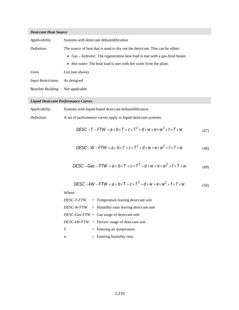
3.210
Desiccant Heat Source
Applicability Systems with desiccant dehumidification
Definition The source of heat that is used to dry out the desiccant. This can be either:
• Gas – hydronic: The regeneration heat load is met with a gas-fired heater.
• Hot water: The heat load is met with hot water from the plant.
Units List (see above)
Input Restrictions As designed
Baseline Building Not applicable
Liquid Desiccant Performance Curves
Applicability Systems with liquid-based desiccant dehumidification
Definition A set of performance curves apply to liquid desiccant systems:
wTfwewdTcTbaFTWTDESC ××+×+×+×+×+=−− 22 (47)
wTfwewdTcTbaFTWWDESC ××+×+×+×+×+=−− 22 (48)
wTfwewdTcTbaFTWGasDESC ××+×+×+×+×+=−− 22 (49)
wTfwewdTcTbaFTWkWDESC ××+×+×+×+×+=−− 22 (50)
Where:
DESC-T-FTW = Temperature leaving desiccant unit
DESC-W-FTW = Humidity ratio leaving desiccant unit
DESC-Gas-FTW = Gas usage of desiccant unit
DESC-kW-FTW = Electric usage of desiccant unit
T = Entering air temperature
w = Entering humidity ratio
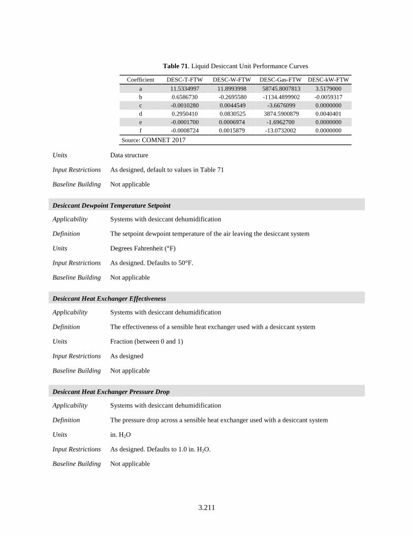
3.211
Table 71. Liquid Desiccant Unit Performance Curves
Coefficient DESC-T-FTW DESC-W-FTW DESC-Gas-FTW DESC-kW-FTW a 11.5334997 11.8993998 58745.8007813 3.5179000 b 0.6586730 -0.2695580 -1134.4899902 -0.0059317 c -0.0010280 0.0044549 -3.6676099 0.0000000 d 0.2950410 0.0830525 3874.5900879 0.0040401 e -0.0001700 0.0006974 -1.6962700 0.0000000 f -0.0008724 0.0015879 -13.0732002 0.0000000
Source: COMNET 2017
Units Data structure
Input Restrictions As designed, default to values in Table 71
Baseline Building Not applicable
Desiccant Dewpoint Temperature Setpoint
Applicability Systems with desiccant dehumidification
Definition The setpoint dewpoint temperature of the air leaving the desiccant system
Units Degrees Fahrenheit (°F)
Input Restrictions As designed. Defaults to 50°F.
Baseline Building Not applicable
Desiccant Heat Exchanger Effectiveness
Applicability Systems with desiccant dehumidification
Definition The effectiveness of a sensible heat exchanger used with a desiccant system
Units Fraction (between 0 and 1)
Input Restrictions As designed
Baseline Building Not applicable
Desiccant Heat Exchanger Pressure Drop
Applicability Systems with desiccant dehumidification
Definition The pressure drop across a sensible heat exchanger used with a desiccant system
Units in. H2O
Input Restrictions As designed. Defaults to 1.0 in. H2O.
Baseline Building Not applicable
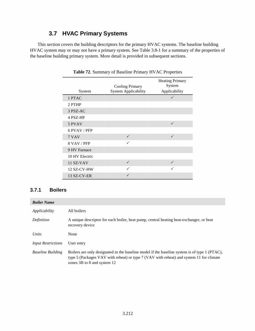
3.212
3.7 HVAC Primary Systems
This section covers the building descriptors for the primary HVAC systems. The baseline building HVAC system may or may not have a primary system. See Table 3.8-1 for a summary of the properties of the baseline building primary system. More detail is provided in subsequent sections.
Table 72. Summary of Baseline Primary HVAC Properties
System Cooling Primary
System Applicability
Heating Primary System
Applicability
1 PTAC 2 PTHP 3 PSZ-AC 4 PSZ-HP 5 PVAV 6 PVAV / PFP 7 VAV 8 VAV / PFP 9 HV Furnace 10 HV Electric 11 SZ-VAV 12 SZ-CV-HW 13 SZ-CV-ER
3.7.1 Boilers
Boiler Name
Applicability All boilers
Definition A unique descriptor for each boiler, heat pump, central heating heat-exchanger, or heat recovery device
Units None
Input Restrictions User entry
Baseline Building Boilers are only designated in the baseline model if the baseline system is of type 1 (PTAC), type 5 (Packages VAV with reheat) or type 7 (VAV with reheat) and system 11 for climate zones 3B to 8 and system 12
3.213
Boiler Fuel
Applicability All boilers
Definition The fuel source for the central heating equipment. The choices are:
• Gas
• Oil
• Electricity
Units List (see above)
Input Restrictions As designed
Baseline Building Same fuel as the proposed design. For fossil fuel systems where natural gas is not available for the proposed building site as determined by the rating authority, the baseline HVAC systems shall be modeled using propane as their fuel.
Boiler Type
Applicability All boilers
Definition The boiler type. Choices include:
• Steam boiler
• Hot water boiler
• Heat-pump water heater
Units List (see above)
Input Restrictions As designed
Baseline Building The boiler type will be a hot water boiler for baseline systems 1, 5, 7, 11, and 12. All other baseline system types do not have a boiler
3.214
Boiler Draft Type
Applicability All boilers
Definition How combustion airflow is drawn through the boiler. Choices are:
• Natural (sometimes called atmospheric)
• Mechanical
Natural draft boilers use natural convection to draw air for combustion through the boiler. Natural draft boilers are subject to outside air conditions and the temperature of the flue gases.
Mechanical draft boilers enhance the airflow in one of three ways: 1) induced draft, which uses ambient air, a steam jet, or a fan to induce a negative pressure that pulls flow through the exhaust stack; 2) forced draft, which uses a fan and ductwork to create a positive pressure that forces air into the furnace; or 3) balanced draft, which uses both induced draft and forced draft methods to bring air through the furnace, usually keeping the pressure slightly below atmospheric.
Units List (see above)
Input Restrictions As designed. Default is natural draft.
Baseline Building The boiler for the baseline system is assumed to be natural draft boiler
Number of Identical Boiler Units
Applicability All boilers
Definition The number of identical units for staging
Units Numeric: integer
Input Restrictions As designed. Default is 1.
Baseline Building The baseline building shall have one boiler when the baseline plant serves a conditioned floor area of 15,000 ft2 or less, and have two equally size boilers for plants serving more than 15,000 ft2
Boiler Heat Loss
Applicability All boilers
Definition The boiler or heat-exchanger heat loss expressed as a percentage of full load output capacity. This loss only occurs when the boiler is firing.
Units Percent (%)
Input Restrictions Default is 2% for electric boilers and heat-exchangers and 0% for fuel-fired boilers. If the user overrides the default, supporting documentation is required.
Baseline Building Prescribed at 2% for electric boilers and heat-exchangers. Prescribed at 0% for fuel-fired boilers, since this loss is already incorporated into the overall thermal efficiency, or AFUE of the boiler.
3.215
For boilers with efficiency rating prescribed as combustion efficiency, 2% jacket losses will be assumed. Hence:
Et = Ec – 2%
Where:
Et = Thermal efficiency
Ec = Combustion efficiency
Boiler Design Capacity
Applicability All boilers
Definition The heating capacity at design conditions
Units Btu/h
Input Restrictions UMLH shall not exceed 300. If they do, the proposed boiler capacity shall be increased incrementally until the unmet loads are reduced to 300 or less.
Baseline Building Autosized, with a heating oversizing factor of 25%. Sizing calculations shall be based on the heating design day and cooling design day conditions, as defined in Section 3.1.5 of this document. Oversizing would be carried out at zone level where the sizing parameters would be applied to the zone design heating loads, but not the airflow rates. Refer to Section 2.6.2 of this document for more details. If the number of UMLH for the baseline exceeds 300, heating coil capacity may need to be increased along with system airflow as described in Section 2.6.2. of this document.
Boiler Efficiency Type
Applicability All boilers
Definition The full load efficiency of a boiler is expressed as one of the following:
• Annual fuel utilization efficiency (AFUE) is a measure of the boiler’s efficiency over a predefined heating season.
• Thermal efficiency (Et) is the ratio of the heat transferred to the water divided by the heat input of the fuel.
• Combustion efficiency (Ec) is the measure of how much energy is extracted from the fuel and is the ratio of heat transferred to the combustion air divided by the heat input of the fuel.
Units List (see above)
Input Restrictions AFUE for all gas and oil-fired boilers with less than 300,000 Btu/h capacity
Et for all gas and oil-fired boilers with capacities between 300,000 and 2,500,000 Btu/h
Ec for all gas and oil-fired boilers with capacities above 2,500,000 Btu/h
Baseline Building Same efficiency type relationship with capacity as described for proposed design
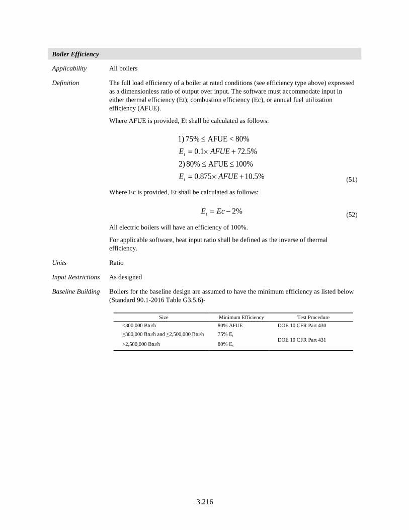
3.216
Boiler Efficiency
Applicability All boilers
Definition The full load efficiency of a boiler at rated conditions (see efficiency type above) expressed as a dimensionless ratio of output over input. The software must accommodate input in either thermal efficiency (Et), combustion efficiency (Ec), or annual fuel utilization efficiency (AFUE).
Where AFUE is provided, Et shall be calculated as follows:
%5.10875.0%100AFUE80% )2
%5.721.080%<AFUE75% 1)
+×=≤≤+×=
≤
AFUEE
AFUEE
t
t
(51)
Where Ec is provided, Et shall be calculated as follows:
%2−= EcEt (52)
All electric boilers will have an efficiency of 100%.
For applicable software, heat input ratio shall be defined as the inverse of thermal efficiency.
Units Ratio
Input Restrictions As designed
Baseline Building Boilers for the baseline design are assumed to have the minimum efficiency as listed below (Standard 90.1-2016 Table G3.5.6)-
Size Minimum Efficiency Test Procedure <300,000 Btu/h 80% AFUE DOE 10 CFR Part 430 ≥300,000 Btu/h and ≤2,500,000 Btu/h 75% Et
DOE 10 CFR Part 431 >2,500,000 Btu/h 80% Ec
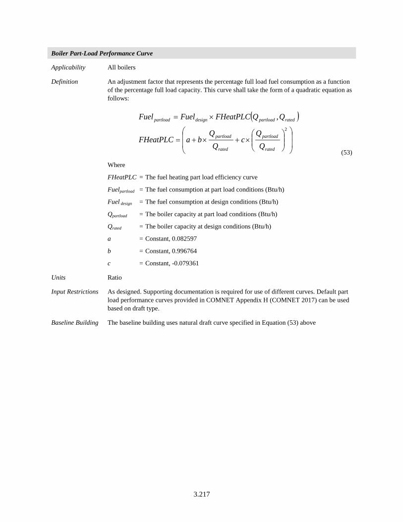
3.217
Boiler Part-Load Performance Curve
Applicability All boilers
Definition An adjustment factor that represents the percentage full load fuel consumption as a function of the percentage full load capacity. This curve shall take the form of a quadratic equation as follows:
( )
×+×+=
×=2
,
rated
partload
rated
partload
ratedpartloaddesignpartload
cQ
QbaFHeatPLC
QQFHeatPLCFuelFuel
(53)
Where
FHeatPLC = The fuel heating part load efficiency curve
Fuelpartload = The fuel consumption at part load conditions (Btu/h)
Fuel design = The fuel consumption at design conditions (Btu/h)
Qpartload = The boiler capacity at part load conditions (Btu/h)
Qrated = The boiler capacity at design conditions (Btu/h)
a = Constant, 0.082597
b = Constant, 0.996764
c = Constant, -0.079361
Units Ratio
Input Restrictions As designed. Supporting documentation is required for use of different curves. Default part load performance curves provided in COMNET Appendix H (COMNET 2017) can be used based on draft type.
Baseline Building The baseline building uses natural draft curve specified in Equation (53) above
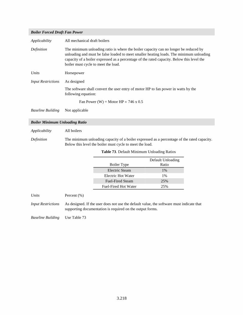
3.218
Boiler Forced Draft Fan Power
Applicability All mechanical draft boilers
Definition The minimum unloading ratio is where the boiler capacity can no longer be reduced by unloading and must be false loaded to meet smaller heating loads. The minimum unloading capacity of a boiler expressed as a percentage of the rated capacity. Below this level the boiler must cycle to meet the load.
Units Horsepower
Input Restrictions As designed
The software shall convert the user entry of motor HP to fan power in watts by the following equation:
Fan Power (W) = Motor HP × 746 x 0.5
Baseline Building Not applicable
Boiler Minimum Unloading Ratio
Applicability All boilers
Definition The minimum unloading capacity of a boiler expressed as a percentage of the rated capacity. Below this level the boiler must cycle to meet the load.
Table 73. Default Minimum Unloading Ratios
Boiler Type Default Unloading
Ratio Electric Steam 1%
Electric Hot Water 1% Fuel-Fired Steam 25%
Fuel-Fired Hot Water 25%
Units Percent (%)
Input Restrictions As designed. If the user does not use the default value, the software must indicate that supporting documentation is required on the output forms.
Baseline Building Use Table 73
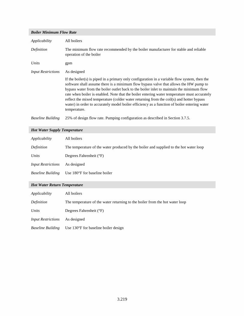
3.219
Boiler Minimum Flow Rate
Applicability All boilers
Definition The minimum flow rate recommended by the boiler manufacturer for stable and reliable operation of the boiler
Units gpm
Input Restrictions As designed
If the boiler(s) is piped in a primary only configuration in a variable flow system, then the software shall assume there is a minimum flow bypass valve that allows the HW pump to bypass water from the boiler outlet back to the boiler inlet to maintain the minimum flow rate when boiler is enabled. Note that the boiler entering water temperature must accurately reflect the mixed temperature (colder water returning from the coil(s) and hotter bypass water) in order to accurately model boiler efficiency as a function of boiler entering water temperature.
Baseline Building 25% of design flow rate. Pumping configuration as described in Section 3.7.5.
Hot Water Supply Temperature
Applicability All boilers
Definition The temperature of the water produced by the boiler and supplied to the hot water loop
Units Degrees Fahrenheit (°F)
Input Restrictions As designed
Baseline Building Use 180°F for baseline boiler
Hot Water Return Temperature
Applicability All boilers
Definition The temperature of the water returning to the boiler from the hot water loop
Units Degrees Fahrenheit (°F)
Input Restrictions As designed
Baseline Building Use 130°F for baseline boiler design
3.220
Hot Water Supply Temperature Reset
Applicability All boilers
Definition Variation of the hot water supply temperature with OAT
Units Degrees Fahrenheit (°F)
Input Restrictions As designed
Baseline Building The hot water supply temperature should vary according to the following:
• 180°F when outside air is < 20°F
• ramp linearly between 180°F and 150°F when outdoor air is between 20°F and 50°F
• 150°F when outdoor air is > 50°F
3.7.2 Chillers
Chiller Name
Applicability All chillers
Definition Unique descriptor for each chiller
Units Text, unique
Input Restrictions User entry. Where applicable, this should match the tags that are used on the plans.
Baseline Building Chillers are only designated when the baseline system is of type 7 (VAV with reheat), 8 (VAV with PFP boxes) 11, 12, and 13
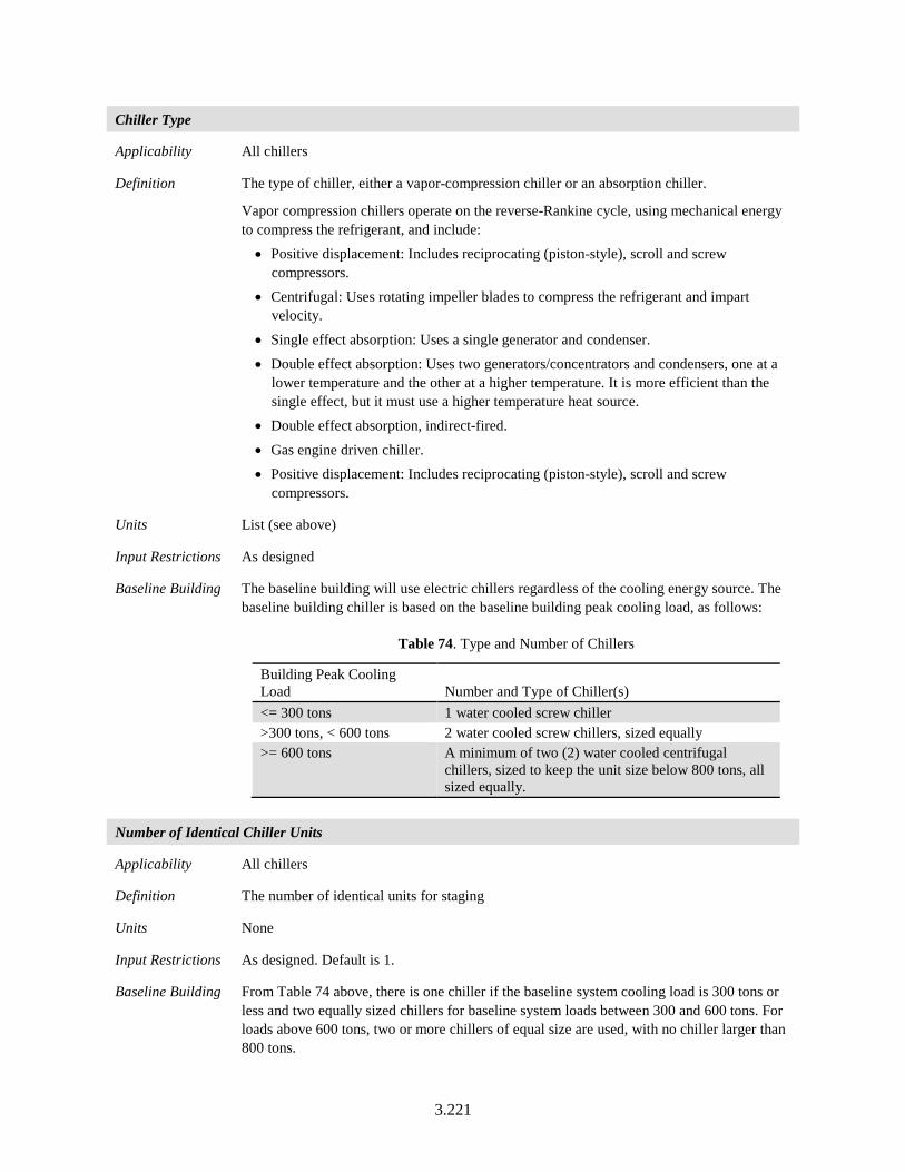
3.221
Chiller Type
Applicability All chillers
Definition The type of chiller, either a vapor-compression chiller or an absorption chiller.
Vapor compression chillers operate on the reverse-Rankine cycle, using mechanical energy to compress the refrigerant, and include:
• Positive displacement: Includes reciprocating (piston-style), scroll and screw compressors.
• Centrifugal: Uses rotating impeller blades to compress the refrigerant and impart velocity.
• Single effect absorption: Uses a single generator and condenser. • Double effect absorption: Uses two generators/concentrators and condensers, one at a
lower temperature and the other at a higher temperature. It is more efficient than the single effect, but it must use a higher temperature heat source.
• Double effect absorption, indirect-fired.
• Gas engine driven chiller. • Positive displacement: Includes reciprocating (piston-style), scroll and screw
compressors.
Units List (see above)
Input Restrictions As designed
Baseline Building The baseline building will use electric chillers regardless of the cooling energy source. The baseline building chiller is based on the baseline building peak cooling load, as follows:
Table 74. Type and Number of Chillers
Building Peak Cooling Load Number and Type of Chiller(s) <= 300 tons 1 water cooled screw chiller >300 tons, < 600 tons 2 water cooled screw chillers, sized equally >= 600 tons A minimum of two (2) water cooled centrifugal
chillers, sized to keep the unit size below 800 tons, all sized equally.
Number of Identical Chiller Units
Applicability All chillers
Definition The number of identical units for staging
Units None
Input Restrictions As designed. Default is 1.
Baseline Building From Table 74 above, there is one chiller if the baseline system cooling load is 300 tons or less and two equally sized chillers for baseline system loads between 300 and 600 tons. For loads above 600 tons, two or more chillers of equal size are used, with no chiller larger than 800 tons.
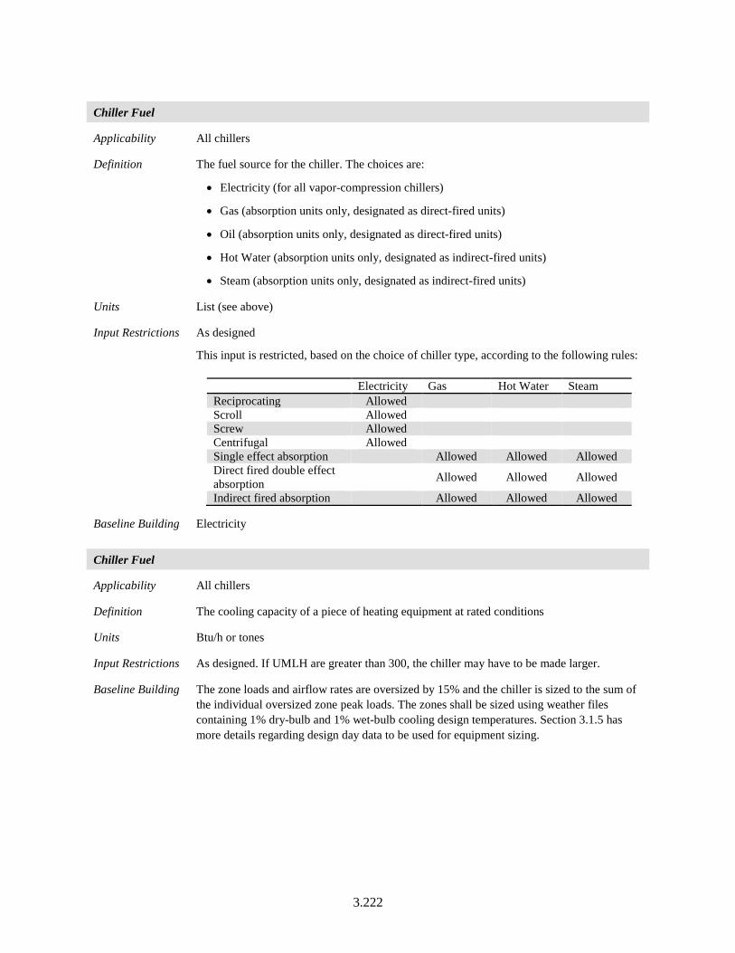
3.222
Chiller Fuel
Applicability All chillers
Definition The fuel source for the chiller. The choices are:
• Electricity (for all vapor-compression chillers)
• Gas (absorption units only, designated as direct-fired units)
• Oil (absorption units only, designated as direct-fired units)
• Hot Water (absorption units only, designated as indirect-fired units)
• Steam (absorption units only, designated as indirect-fired units)
Units List (see above)
Input Restrictions As designed
This input is restricted, based on the choice of chiller type, according to the following rules:
Electricity Gas Hot Water Steam Reciprocating Allowed Scroll Allowed Screw Allowed Centrifugal Allowed Single effect absorption Allowed Allowed Allowed Direct fired double effect absorption Allowed Allowed Allowed
Indirect fired absorption Allowed Allowed Allowed
Baseline Building Electricity
Chiller Fuel
Applicability All chillers
Definition The cooling capacity of a piece of heating equipment at rated conditions
Units Btu/h or tones
Input Restrictions As designed. If UMLH are greater than 300, the chiller may have to be made larger.
Baseline Building The zone loads and airflow rates are oversized by 15% and the chiller is sized to the sum of the individual oversized zone peak loads. The zones shall be sized using weather files containing 1% dry-bulb and 1% wet-bulb cooling design temperatures. Section 3.1.5 has more details regarding design day data to be used for equipment sizing.
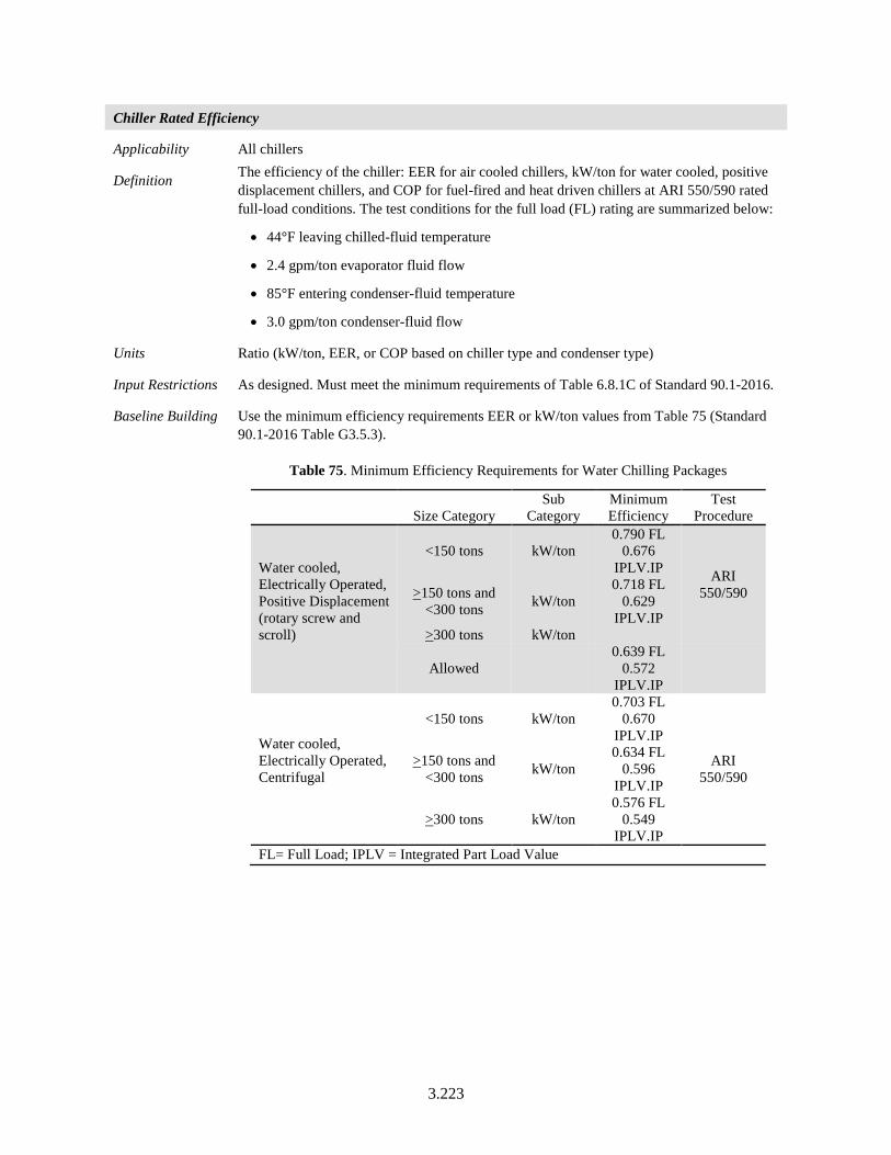
3.223
Chiller Rated Efficiency
Applicability All chillers
Definition The efficiency of the chiller: EER for air cooled chillers, kW/ton for water cooled, positive displacement chillers, and COP for fuel-fired and heat driven chillers at ARI 550/590 rated full-load conditions. The test conditions for the full load (FL) rating are summarized below:
• 44°F leaving chilled-fluid temperature
• 2.4 gpm/ton evaporator fluid flow
• 85°F entering condenser-fluid temperature
• 3.0 gpm/ton condenser-fluid flow
Units Ratio (kW/ton, EER, or COP based on chiller type and condenser type)
Input Restrictions As designed. Must meet the minimum requirements of Table 6.8.1C of Standard 90.1-2016.
Baseline Building Use the minimum efficiency requirements EER or kW/ton values from Table 75 (Standard 90.1-2016 Table G3.5.3).
Table 75. Minimum Efficiency Requirements for Water Chilling Packages
Size Category Sub
Category Minimum Efficiency
Test Procedure
Water cooled, Electrically Operated, Positive Displacement (rotary screw and scroll)
<150 tons kW/ton 0.790 FL
0.676 IPLV.IP ARI
550/590 >150 tons and <300 tons kW/ton
0.718 FL 0.629
IPLV.IP >300 tons kW/ton
Allowed 0.639 FL
0.572 IPLV.IP
Water cooled, Electrically Operated, Centrifugal
<150 tons kW/ton 0.703 FL
0.670 IPLV.IP
ARI 550/590
>150 tons and <300 tons kW/ton
0.634 FL 0.596
IPLV.IP
>300 tons kW/ton 0.576 FL
0.549 IPLV.IP
FL= Full Load; IPLV = Integrated Part Load Value
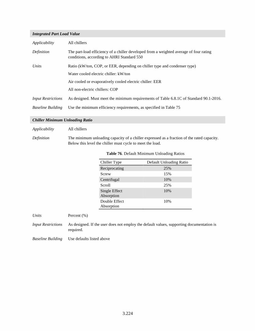
3.224
Integrated Part Load Value
Applicability All chillers
Definition The part-load efficiency of a chiller developed from a weighted average of four rating conditions, according to AHRI Standard 550
Units Ratio (kW/ton, COP, or EER, depending on chiller type and condenser type)
Water cooled electric chiller: kW/ton
Air cooled or evaporatively cooled electric chiller: EER
All non-electric chillers: COP
Input Restrictions As designed. Must meet the minimum requirements of Table 6.8.1C of Standard 90.1-2016.
Baseline Building Use the minimum efficiency requirements, as specified in Table 75
Chiller Minimum Unloading Ratio
Applicability All chillers
Definition The minimum unloading capacity of a chiller expressed as a fraction of the rated capacity. Below this level the chiller must cycle to meet the load.
Table 76. Default Minimum Unloading Ratios
Chiller Type Default Unloading Ratio Reciprocating 25% Screw 15% Centrifugal 10% Scroll 25% Single Effect Absorption
10%
Double Effect Absorption
10%
Units Percent (%)
Input Restrictions As designed. If the user does not employ the default values, supporting documentation is required.
Baseline Building Use defaults listed above
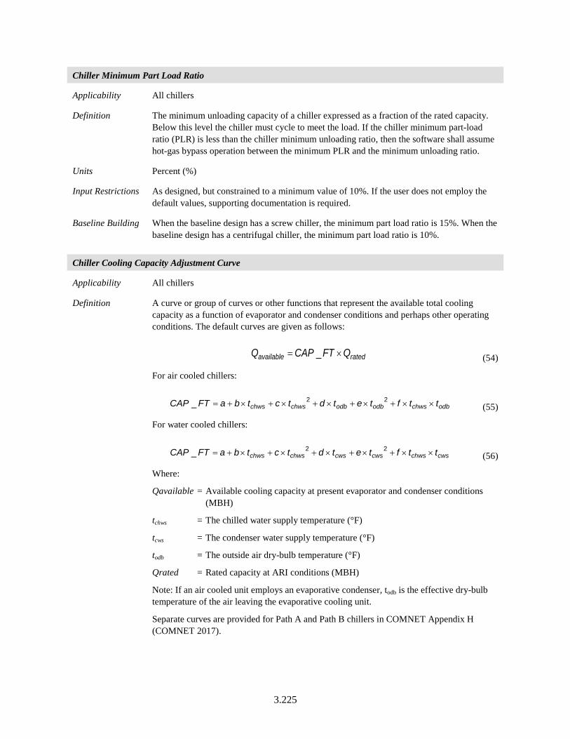
3.225
Chiller Minimum Part Load Ratio
Applicability All chillers
Definition The minimum unloading capacity of a chiller expressed as a fraction of the rated capacity. Below this level the chiller must cycle to meet the load. If the chiller minimum part-load ratio (PLR) is less than the chiller minimum unloading ratio, then the software shall assume hot-gas bypass operation between the minimum PLR and the minimum unloading ratio.
Units Percent (%)
Input Restrictions As designed, but constrained to a minimum value of 10%. If the user does not employ the default values, supporting documentation is required.
Baseline Building When the baseline design has a screw chiller, the minimum part load ratio is 15%. When the baseline design has a centrifugal chiller, the minimum part load ratio is 10%.
Chiller Cooling Capacity Adjustment Curve
Applicability All chillers
Definition A curve or group of curves or other functions that represent the available total cooling capacity as a function of evaporator and condenser conditions and perhaps other operating conditions. The default curves are given as follows:
ratedavailable QFTCAPQ ×= _ (54)
For air cooled chillers:
odbchwsodbodbchwschws ttftetdtctbaFTCAP ××+×+×+×+×+= 22_ (55)
For water cooled chillers:
cwschwscwscwschwschws ttftetdtctbaFTCAP ××+×+×+×+×+= 22_ (56)
Where:
Qavailable = Available cooling capacity at present evaporator and condenser conditions (MBH)
tchws = The chilled water supply temperature (°F)
tcws = The condenser water supply temperature (°F)
todb = The outside air dry-bulb temperature (°F)
Qrated = Rated capacity at ARI conditions (MBH)
Note: If an air cooled unit employs an evaporative condenser, todb is the effective dry-bulb temperature of the air leaving the evaporative cooling unit.
Separate curves are provided for Path A and Path B chillers in COMNET Appendix H (COMNET 2017).
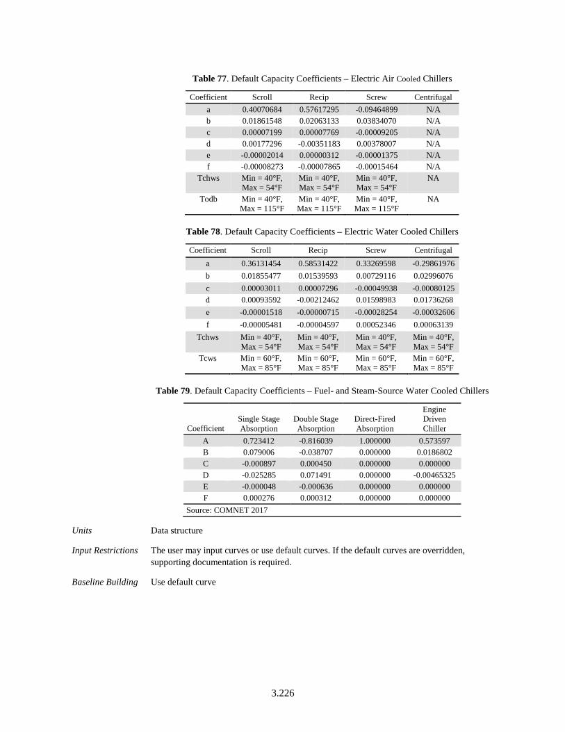
3.226
Table 77. Default Capacity Coefficients – Electric Air Cooled Chillers
Coefficient Scroll Recip Screw Centrifugal a 0.40070684 0.57617295 -0.09464899 N/A b 0.01861548 0.02063133 0.03834070 N/A c 0.00007199 0.00007769 -0.00009205 N/A d 0.00177296 -0.00351183 0.00378007 N/A e -0.00002014 0.00000312 -0.00001375 N/A f -0.00008273 -0.00007865 -0.00015464 N/A
Tchws Min = 40°F, Max = 54°F
Min = 40°F, Max = 54°F
Min = 40°F, Max = 54°F
NA
Todb Min = 40°F, Max = 115°F
Min = 40°F, Max = 115°F
Min = 40°F, Max = 115°F
NA
Table 78. Default Capacity Coefficients – Electric Water Cooled Chillers
Coefficient Scroll Recip Screw Centrifugal a 0.36131454 0.58531422 0.33269598 -0.29861976 b 0.01855477 0.01539593 0.00729116 0.02996076 c 0.00003011 0.00007296 -0.00049938 -0.00080125 d 0.00093592 -0.00212462 0.01598983 0.01736268 e -0.00001518 -0.00000715 -0.00028254 -0.00032606 f -0.00005481 -0.00004597 0.00052346 0.00063139
Tchws Min = 40°F, Max = 54°F
Min = 40°F, Max = 54°F
Min = 40°F, Max = 54°F
Min = 40°F, Max = 54°F
Tcws Min = 60°F, Max = 85°F
Min = 60°F, Max = 85°F
Min = 60°F, Max = 85°F
Min = 60°F, Max = 85°F
Table 79. Default Capacity Coefficients – Fuel- and Steam-Source Water Cooled Chillers
Coefficient Single Stage Absorption
Double Stage Absorption
Direct-Fired Absorption
Engine Driven Chiller
A 0.723412 -0.816039 1.000000 0.573597 B 0.079006 -0.038707 0.000000 0.0186802 C -0.000897 0.000450 0.000000 0.000000 D -0.025285 0.071491 0.000000 -0.00465325 E -0.000048 -0.000636 0.000000 0.000000 F 0.000276 0.000312 0.000000 0.000000
Source: COMNET 2017
Units Data structure
Input Restrictions The user may input curves or use default curves. If the default curves are overridden, supporting documentation is required.
Baseline Building Use default curve
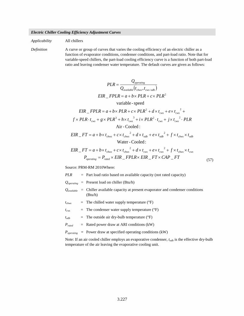
3.227
Electric Chiller Cooling Efficiency Adjustment Curves
Applicability All chillers
Definition A curve or group of curves that varies the cooling efficiency of an electric chiller as a function of evaporator conditions, condenser conditions, and part-load ratio. Note that for variable-speed chillers, the part-load cooling efficiency curve is a function of both part-load ratio and leaving condenser water temperature. The default curves are given as follows:
( )
FTCAPFTEIRFPLREIRPPttftetdtctbaFTEIR
ttftetdtctbaFTEIR
PLRtjtPLRithPLRgtPLRf
tetdPLRcPLRbaFPLREIR
PLRcPLRbaFPLREIRttQ
QPLR
ratedoperating
cwschwscwscwschwschws
odbchwsodbodbchwschws
cwscwscwscws
cwscws
odbcwschwsavailable
operating
____
: Cooled-Water_
:Cooled-Air
_
speed-variable_
,
22
22
2233
22
2/
×××=××+×+×+×+×+=
××+×+×+×+×+=
⋅×+⋅×+×+×+⋅×
+×+×+×+×+=
×+×+=
=
(57)
Source: PRM-RM 2010Where:
PLR = Part load ratio based on available capacity (not rated capacity)
Qoperating = Present load on chiller (Btu/h)
Qavailable = Chiller available capacity at present evaporator and condenser conditions (Btu/h)
tchws = The chilled water supply temperature (°F)
tcws = The condenser water supply temperature (°F)
todb = The outside air dry-bulb temperature (°F)
Prated = Rated power draw at ARI conditions (kW)
Poperating = Power draw at specified operating conditions (kW)
Note: If an air cooled chiller employs an evaporative condenser, todb is the effective dry-bulb temperature of the air leaving the evaporative cooling unit.
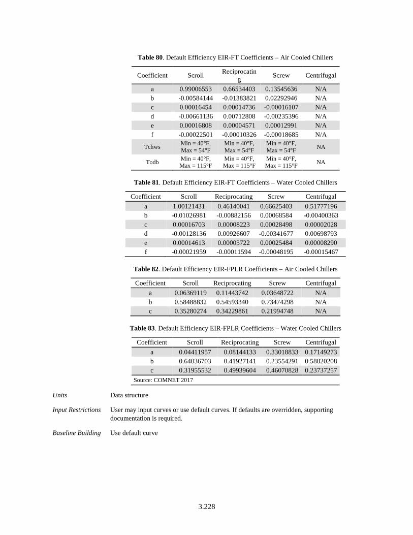
3.228
Table 80. Default Efficiency EIR-FT Coefficients – Air Cooled Chillers
Coefficient Scroll Reciprocating Screw Centrifugal
a 0.99006553 0.66534403 0.13545636 N/A b -0.00584144 -0.01383821 0.02292946 N/A c 0.00016454 0.00014736 -0.00016107 N/A d -0.00661136 0.00712808 -0.00235396 N/A e 0.00016808 0.00004571 0.00012991 N/A f -0.00022501 -0.00010326 -0.00018685 N/A
Tchws Min = 40°F, Max = 54°F
Min = 40°F, Max = 54°F
Min = 40°F, Max = 54°F NA
Todb Min = 40°F, Max = 115°F
Min = 40°F, Max = 115°F
Min = 40°F, Max = 115°F NA
Table 81. Default Efficiency EIR-FT Coefficients – Water Cooled Chillers
Coefficient Scroll Reciprocating Screw Centrifugal a 1.00121431 0.46140041 0.66625403 0.51777196 b -0.01026981 -0.00882156 0.00068584 -0.00400363 c 0.00016703 0.00008223 0.00028498 0.00002028 d -0.00128136 0.00926607 -0.00341677 0.00698793 e 0.00014613 0.00005722 0.00025484 0.00008290 f -0.00021959 -0.00011594 -0.00048195 -0.00015467
Table 82. Default Efficiency EIR-FPLR Coefficients – Air Cooled Chillers
Coefficient Scroll Reciprocating Screw Centrifugal a 0.06369119 0.11443742 0.03648722 N/A b 0.58488832 0.54593340 0.73474298 N/A c 0.35280274 0.34229861 0.21994748 N/A
Table 83. Default Efficiency EIR-FPLR Coefficients – Water Cooled Chillers
Coefficient Scroll Reciprocating Screw Centrifugal a 0.04411957 0.08144133 0.33018833 0.17149273 b 0.64036703 0.41927141 0.23554291 0.58820208 c 0.31955532 0.49939604 0.46070828 0.23737257
Source: COMNET 2017
Units Data structure
Input Restrictions User may input curves or use default curves. If defaults are overridden, supporting documentation is required.
Baseline Building Use default curve
3.229
Chilled Water Supply Temperature
Applicability All chillers
Definition The chilled water supply temperature of the chiller at design conditions
Units Degrees Fahrenheit (°F)
Input Restrictions As designed
Baseline Building The baseline chilled water supply temperature is set to 44°F
Chilled Water Return Temperature
Applicability All chillers
Definition The chilled water return temperature setpoint
Units Degrees Fahrenheit (°F)
Input Restrictions As designed
Baseline Building The baseline chilled water return temperature is set to 56°F
Chilled Water Supply Temperature Control Type
Applicability All chillers
Definition The method by which the chilled water setpoint temperature is reset. The chilled water setpoint may be reset based on demand or OAT.
Units List
Input Restrictions None, can be either “outside air-based reset” or “demand-based reset”
Baseline Building Outside air based reset
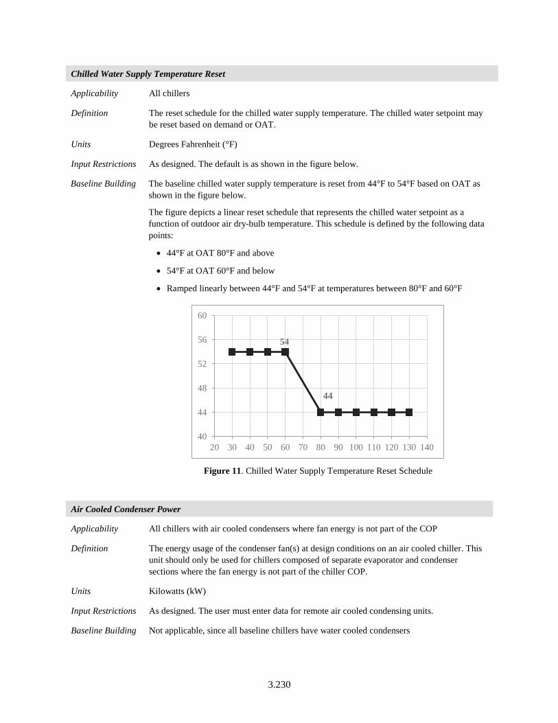
3.230
Chilled Water Supply Temperature Reset
Applicability All chillers
Definition The reset schedule for the chilled water supply temperature. The chilled water setpoint may be reset based on demand or OAT.
Units Degrees Fahrenheit (°F)
Input Restrictions As designed. The default is as shown in the figure below.
Baseline Building The baseline chilled water supply temperature is reset from 44°F to 54°F based on OAT as shown in the figure below.
The figure depicts a linear reset schedule that represents the chilled water setpoint as a function of outdoor air dry-bulb temperature. This schedule is defined by the following data points:
• 44°F at OAT 80°F and above
• 54°F at OAT 60°F and below
• Ramped linearly between 44°F and 54°F at temperatures between 80°F and 60°F
Figure 11. Chilled Water Supply Temperature Reset Schedule
Air Cooled Condenser Power
Applicability All chillers with air cooled condensers where fan energy is not part of the COP
Definition The energy usage of the condenser fan(s) at design conditions on an air cooled chiller. This unit should only be used for chillers composed of separate evaporator and condenser sections where the fan energy is not part of the chiller COP.
Units Kilowatts (kW)
Input Restrictions As designed. The user must enter data for remote air cooled condensing units.
Baseline Building Not applicable, since all baseline chillers have water cooled condensers
54
44
40
44
48
52
56
60
20 30 40 50 60 70 80 90 100 110 120 130 140
3.231
3.7.3 Cooling Towers
Baseline building systems 7, 8, and 11 through 13, have one or more cooling towers. One tower is assumed to be matched to each baseline building chiller. Each baseline building chiller has its own condenser water pump that operates when the chiller is brought into service. The range between the condenser water return (CWR) and condenser water supply (CWS) is 10°F so that condenser water flow is a constant 2.5 gpm per cooling ton.5 The baseline building pumping energy is assumed to be 19 W/gpm. The baseline building cooling tower is assumed to have a variable speed fan that is controlled to provide a CWS equal to 70°F when weather permits. The tower fan would operate to maintain a CWS of 70 °F at low wet-bulb conditions. Under cooling conditions closer to design conditions, the CWS floats up to a maximum of 85 °F (the design condition).
The baseline building condenser water design supply temperature shall be calculated using the cooling tower approach to the 0.4% evaporation design wet-bulb temperature as generated by the formula below, with a design temperature rise of 10°F.
Approach 10°F Range = 25.72 – (0.24 × WB)
where WB is the 0.4% evaporation design wet-bulb temperature in °F; valid for wet bulbs from 55°F to 90°F.
The tower shall be controlled to maintain a leaving water temperature based on climate zone (see below), floating up to the design leaving water temperature for the cooling tower.
Climate Zone Leaving Water Temperature 5B, 5C, 6B, 8 65°F 0B, 1B, 2B, 3B, 3C, 4B, 4C, 5A, 6A, 7 70°F 3A,4A 75°F 0A, 1A, 2A 80°F
Cooling Tower Name
Applicability All cooling towers
Definition A unique descriptor for each cooling tower
Units Text, unique
Input Restrictions User entry. Where applicable, this should match the tags that are used on the plans.
Baseline Building Descriptive name that keys the baseline building plant
5 Cooling capacity is related to flow and delta-T through the equation Q = 500 * GPM * Delta-T. When Q is one ton (12,000 Btu/h), GPM = 24 / Delta-T and Delta-T = 24 / GPM
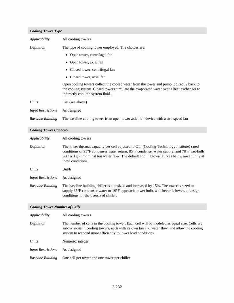
3.232
Cooling Tower Type
Applicability All cooling towers
Definition The type of cooling tower employed. The choices are:
• Open tower, centrifugal fan
• Open tower, axial fan
• Closed tower, centrifugal fan
• Closed tower, axial fan
Open cooling towers collect the cooled water from the tower and pump it directly back to the cooling system. Closed towers circulate the evaporated water over a heat exchanger to indirectly cool the system fluid.
Units List (see above)
Input Restrictions As designed
Baseline Building The baseline cooling tower is an open tower axial fan device with a two speed fan
Cooling Tower Capacity
Applicability All cooling towers
Definition The tower thermal capacity per cell adjusted to CTI (Cooling Technology Institute) rated conditions of 95°F condenser water return, 85°F condenser water supply, and 78°F wet-bulb with a 3 gpm/nominal ton water flow. The default cooling tower curves below are at unity at these conditions.
Units But/h
Input Restrictions As designed
Baseline Building The baseline building chiller is autosized and increased by 15%. The tower is sized to supply 85°F condenser water or 10°F approach to wet bulb, whichever is lower, at design conditions for the oversized chiller.
Cooling Tower Number of Cells
Applicability All cooling towers
Definition The number of cells in the cooling tower. Each cell will be modeled as equal size. Cells are subdivisions in cooling towers, each with its own fan and water flow, and allow the cooling system to respond more efficiently to lower load conditions.
Units Numeric: integer
Input Restrictions As designed
Baseline Building One cell per tower and one tower per chiller
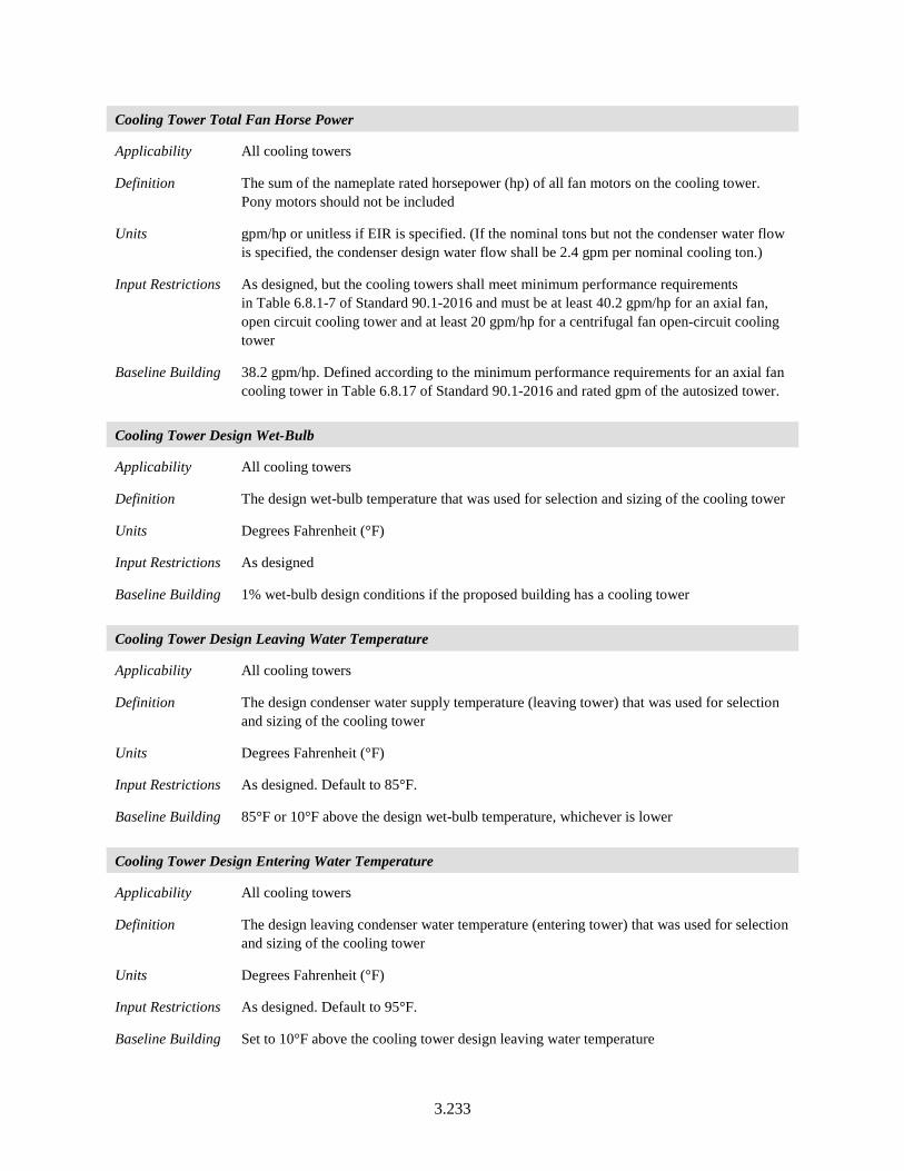
3.233
Cooling Tower Total Fan Horse Power
Applicability All cooling towers
Definition The sum of the nameplate rated horsepower (hp) of all fan motors on the cooling tower. Pony motors should not be included
Units gpm/hp or unitless if EIR is specified. (If the nominal tons but not the condenser water flow is specified, the condenser design water flow shall be 2.4 gpm per nominal cooling ton.)
Input Restrictions As designed, but the cooling towers shall meet minimum performance requirements in Table 6.8.1-7 of Standard 90.1-2016 and must be at least 40.2 gpm/hp for an axial fan, open circuit cooling tower and at least 20 gpm/hp for a centrifugal fan open-circuit cooling tower
Baseline Building 38.2 gpm/hp. Defined according to the minimum performance requirements for an axial fan cooling tower in Table 6.8.17 of Standard 90.1-2016 and rated gpm of the autosized tower.
Cooling Tower Design Wet-Bulb
Applicability All cooling towers
Definition The design wet-bulb temperature that was used for selection and sizing of the cooling tower
Units Degrees Fahrenheit (°F)
Input Restrictions As designed
Baseline Building 1% wet-bulb design conditions if the proposed building has a cooling tower
Cooling Tower Design Leaving Water Temperature
Applicability All cooling towers
Definition The design condenser water supply temperature (leaving tower) that was used for selection and sizing of the cooling tower
Units Degrees Fahrenheit (°F)
Input Restrictions As designed. Default to 85°F.
Baseline Building 85°F or 10°F above the design wet-bulb temperature, whichever is lower
Cooling Tower Design Entering Water Temperature
Applicability All cooling towers
Definition The design leaving condenser water temperature (entering tower) that was used for selection and sizing of the cooling tower
Units Degrees Fahrenheit (°F)
Input Restrictions As designed. Default to 95°F.
Baseline Building Set to 10°F above the cooling tower design leaving water temperature

3.234
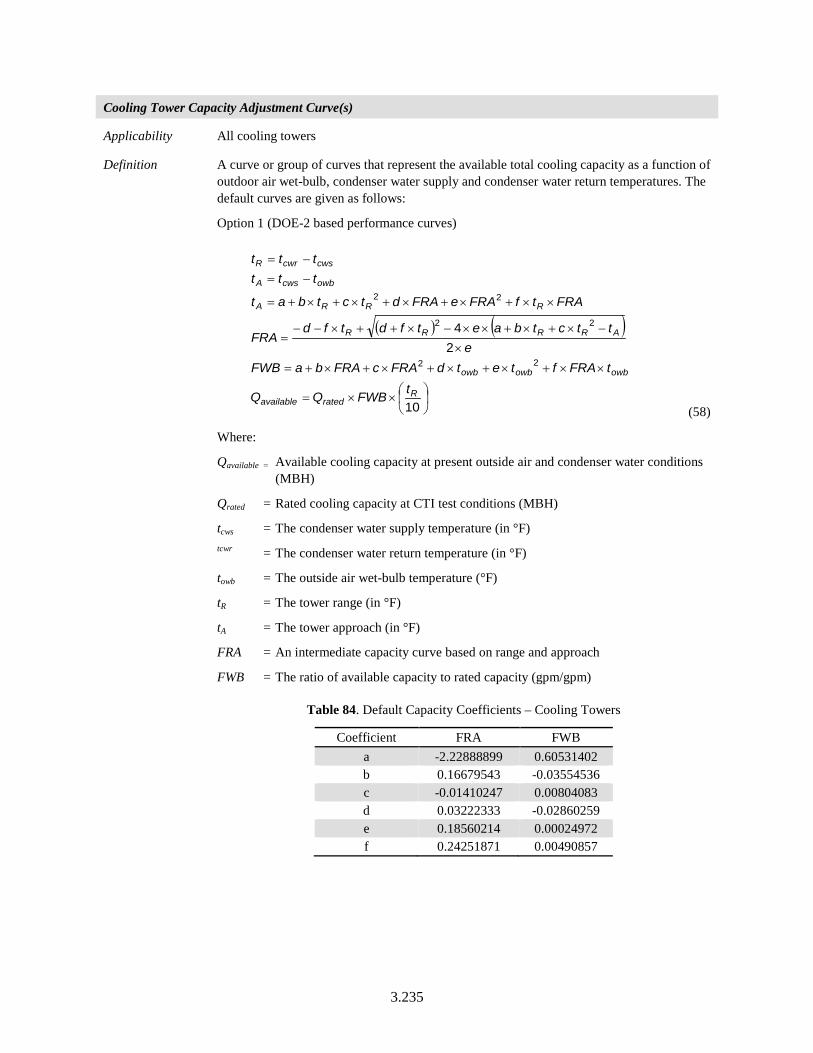
3.235
Cooling Tower Capacity Adjustment Curve(s)
Applicability All cooling towers
Definition A curve or group of curves that represent the available total cooling capacity as a function of outdoor air wet-bulb, condenser water supply and condenser water return temperatures. The default curves are given as follows:
Option 1 (DOE-2 based performance curves)
( ) ( )
××=
××+×+×+×+×+=
×
−×+×+××−×++×−−=
××+×+×+×+×+=
−=
−=
10
24
22
22
22
Rratedavailable
owbowbowb
ARRRR
RRRA
owbcwsA
cwscwrR
tFWBQQ
tFRAftetdFRAcFRAbaFWBe
ttctbaetfdtfdFRA
FRAtfFRAeFRAdtctbat
tttttt
(58)
Where:
Qavailable = Available cooling capacity at present outside air and condenser water conditions (MBH)
Qrated = Rated cooling capacity at CTI test conditions (MBH)
tcws = The condenser water supply temperature (in °F) tcwr = The condenser water return temperature (in °F)
towb = The outside air wet-bulb temperature (°F)
tR = The tower range (in °F)
tA = The tower approach (in °F)
FRA = An intermediate capacity curve based on range and approach
FWB = The ratio of available capacity to rated capacity (gpm/gpm)
Table 84. Default Capacity Coefficients – Cooling Towers
Coefficient FRA FWB a -2.22888899 0.60531402 b 0.16679543 -0.03554536 c -0.01410247 0.00804083 d 0.03222333 -0.02860259 e 0.18560214 0.00024972 f 0.24251871 0.00490857

3.236
Option 2: CoolTools performance curve (EnergyPlus)
Approach = Coeff(1) + Coeff(2)•FRair + Coeff(3)•(FRair)2 +Coeff(4)•(FRair)3 + Coeff(5)•FRwater + Coeff(6)•FRair•FRwater + Coeff(7)•(FRair)2•FRwater +
Coeff(8)•(FRwater)2 + Coeff(9)•FRair•(FRwater)2 + Coeff(10)•(FRwater)3 + Coeff(11)•Twb + Coeff(12)•FRair•Twb + Coeff(13)•(FRair)2•Twb + Coeff(14)•FRwater•Twb + Coeff(15)•FRair•FRwater•Twb + Coeff(16)•(FRwater)2•Twb
+ Coeff(17)•(Twb)2 + Coeff(18)•FRair•(Twb)2 + Coeff(19)•FRwater•(Twb)2 +
Coeff(20)•(Twb)3 + Coeff(21)•Tr + Coeff(22)•FRair•Tr + Coeff(23)•FRair•FRair•Tr + Coeff(24)•FRwater•Tr + Coeff(25)•FRair•FRwater•Tr +
Coeff(26)•(FRwater)2•Tr + Coeff(27)•Twb•Tr + Coeff(28)•FRair•Twb•Tr + Coeff(29)•FRwater•Twb•Tr +
Coeff(30)•(Twb)2•Tr + Coeff(31)•(Tr)2 + Coeff(32)•FRair•(Tr)2 + Coeff(33)•FRwater•(Tr)2
+ Coeff(34)•Twb•(Tr)2 + Coeff(35)•(Tr)3
Where:
FRair = Ratio of airflow to airflow at design conditions
FRwater = Ratio of water flow to water flow at design conditions
Tr = Tower range (°F)
Twb = Wet-Bulb temperature
Coefficients for this performance curve are provided in COMNET Appendix H (COMNET 2017).
Units Data structure
Input Restrictions User may input curves or use one of the two default curves. If defaults are overridden, the rating software must indicate that supporting documentation is required on the output forms.
Baseline Building Use one of the two default curves
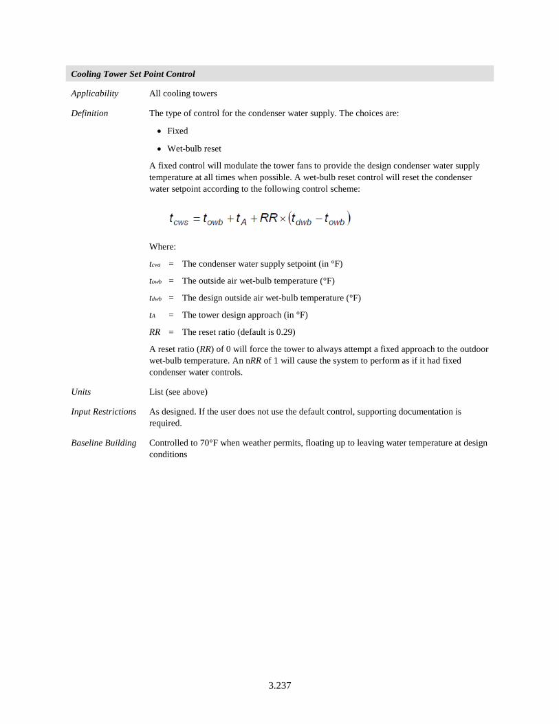
3.237
Cooling Tower Set Point Control
Applicability All cooling towers
Definition The type of control for the condenser water supply. The choices are:
• Fixed
• Wet-bulb reset
A fixed control will modulate the tower fans to provide the design condenser water supply temperature at all times when possible. A wet-bulb reset control will reset the condenser water setpoint according to the following control scheme:
Where:
tcws = The condenser water supply setpoint (in °F)
towb = The outside air wet-bulb temperature (°F)
tdwb = The design outside air wet-bulb temperature (°F)
tA = The tower design approach (in °F)
RR = The reset ratio (default is 0.29)
A reset ratio (RR) of 0 will force the tower to always attempt a fixed approach to the outdoor wet-bulb temperature. An nRR of 1 will cause the system to perform as if it had fixed condenser water controls.
Units List (see above)
Input Restrictions As designed. If the user does not use the default control, supporting documentation is required.
Baseline Building Controlled to 70°F when weather permits, floating up to leaving water temperature at design conditions
3.238
Cooling Tower Capacity Control
Applicability All cooling towers
Definition Describes the modulation control employed in the cooling tower. Choices include:
• Fluid bypass: Provides a parallel path to divert some of the condenser water around the cooling tower at part-load conditions.
• Fan cycling: A simple method of capacity control where the tower fan is cycled on and off. This is often used on multiple-cell installations.
• Two-speed fan/pony motor: From an energy perspective, these are the same. A lower horsepower pony motor is an alternative to a two-speed motor; the pony motor runs at part-load conditions (instead of the full sized motor) and saves fan energy when the tower load is reduced. Additional building descriptors are triggered when this method of capacity control is selected.
• Variable Speed fan: A variable frequency drive is installed for the tower fan so that the speed can be modulated.
Units List (see above)
Input Restrictions As designed
Baseline Building Variable speed fans
Cooling Tower Low-Speed Airflow Ratio
Applicability All cooling towers with variable speed, two-speed, or pony motors
Definition The percentage full load airflow that the tower has at low speed or with the pony motor operating. This is equivalent to the percentage full load capacity when operating at low speed.
Units Fraction (between 0 and 1)
Input Restrictions As designed
Baseline Building 0.50
Cooling Tower Low-Speed kW Ratio
Applicability All cooling towers
Definition The percentage full load power that the tower fans draw at low speed or with the pony motor operating
Units Fraction (between 0 and 1)
Input Restrictions Calculated, using the as-designed flow ratio and the cooling tower power adjustment curve below
Baseline Building 0.30
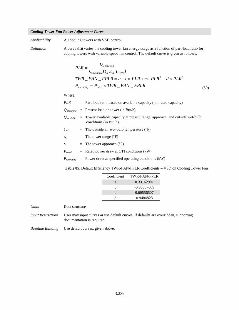
3.239
Cooling Tower Fan Power Adjustment Curve
Applicability All cooling towers with VSD control
Definition A curve that varies the cooling tower fan energy usage as a function of part-load ratio for cooling towers with variable speed fan control. The default curve is given as follows:
( )
FPLRFANTWRPPPLRdPLRcPLRbaFPLRFANTWR
tttQQ
PLR
ratedoperating
OWBARavailable
operating
____
,,32
×=×+×+×+=
=
(59)
Where:
PLR = Part load ratio based on available capacity (not rated capacity)
Qoperating = Present load on tower (in Btu/h)
Qavailable = Tower available capacity at present range, approach, and outside wet-bulb conditions (in Btu/h).
towb = The outside air wet-bulb temperature (°F)
tR = The tower range (°F)
tA = The tower approach (°F)
Prated = Rated power draw at CTI conditions (kW)
Poperating = Power draw at specified operating conditions (kW)
Table 85. Default Efficiency TWR-FAN-FPLR Coefficients – VSD on Cooling Tower Fan
Coefficient TWR-FAN-FPLR a 0.33162901 b -0.88567609 c 0.60556507 d 0.9484823
Units Data structure
Input Restrictions User may input curves or use default curves. If defaults are overridden, supporting documentation is required.
Baseline Building Use default curves, given above.
3.240
Cooling Tower Minimum Speed
Applicability All cooling towers with a VSD control
Definition The minimum fan speed setting of a VSD controlling a cooling tower fan expressed as a ratio of full load speed
Units Fraction (between 0 and 1)
Input Restrictions As designed. The default is 0.40.
Baseline Building Not applicable
3.7.4 Fluid Economizers
Baseline Building Summary:
Baseline building system 11 would include an integrated fluid economizer, meeting the requirements as specified in this section, also in Section 6.5.1.2 of Standard 90.1-2016. Additional inputs to those below may be required to simulate actual control sequences.
Fluid Economizer Name
Applicability All fluid economizers
Definition The name of a fluid economizer for a cooling system
Units Text, unique
Input Restrictions As designed
Baseline Building A water side fluid economizer will be modeled for baseline system 11, for computer rooms
3.241
Water Economizer Type
Applicability All fluid economizers
Definition The type of fluid economizer. Choices include:
• None
• Heat exchanger in parallel with chillers: This would be used with an open cooling tower combined with a heat exchanger or evaporative cooler (closed circuit cooling tower) and is a non-integrated economizer, because the chillers are locked out when the plant is in economizer mode.
• Heat exchanger in series with chillers: This would be used with an open cooling tower and heat exchanger or evaporative cooler (closed circuit cooling tower) and is integrated because the piping is arranged so the chilled water return is precooled and chillers can operate simultaneously with water economizer operation. Depending on the proportion of water economizer capacity compared to chiller capacity, the water economizer heat exchanger may see the full chilled water flow, or be in a “sidecar” arrangement where only a portion of the chilled water flow goes through the heat exchanger.
• Direct water economizer: In this system, the condenser and chilled-water systems are connected. When the outdoor wet bulb temperature is low enough, cold water from the cooling tower is routed directly into the chilled-water loop. This would be used with filtration of the condenser water. In this case, a heat exchanger is not needed. This type can work as either an integrated or a non-integrated economizer, depending on piping arrangement. Although the strainer cycle is the most efficient water economizer option, it greatly increases the risk of fouling in the chilled-water system and cooling coils with the same type of contamination that is common in open cooling-tower systems. A strainer or filter can be used to minimize this contamination, but the potential for fouling prevents widespread use of the strainer-cycle system (Trane, 2016).
Units List (see above)
Input Restrictions As designed
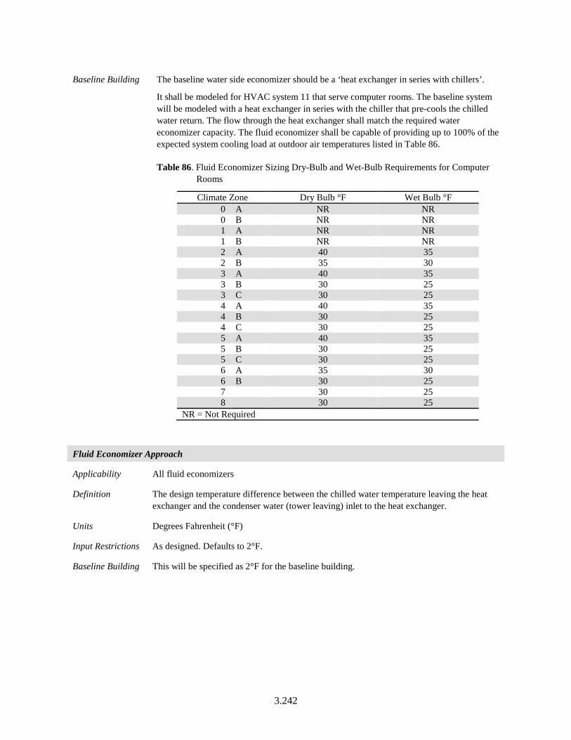
3.242
Baseline Building The baseline water side economizer should be a ‘heat exchanger in series with chillers’.
It shall be modeled for HVAC system 11 that serve computer rooms. The baseline system will be modeled with a heat exchanger in series with the chiller that pre-cools the chilled water return. The flow through the heat exchanger shall match the required water economizer capacity. The fluid economizer shall be capable of providing up to 100% of the expected system cooling load at outdoor air temperatures listed in Table 86.
Table 86. Fluid Economizer Sizing Dry-Bulb and Wet-Bulb Requirements for Computer Rooms
Climate Zone Dry Bulb °F Wet Bulb °F 0 A NR NR 0 B NR NR 1 A NR NR 1 B NR NR 2 A 40 35 2 B 35 30 3 A 40 35 3 B 30 25 3 C 30 25 4 A 40 35 4 B 30 25 4 C 30 25 5 A 40 35 5 B 30 25 5 C 30 25 6 A 35 30 6 B 30 25 7 30 25 8 30 25
NR = Not Required
Fluid Economizer Approach
Applicability All fluid economizers
Definition The design temperature difference between the chilled water temperature leaving the heat exchanger and the condenser water (tower leaving) inlet to the heat exchanger.
Units Degrees Fahrenheit (°F)
Input Restrictions As designed. Defaults to 2°F.
Baseline Building This will be specified as 2°F for the baseline building.
3.243
Fluid Economizer Activation Temperature Difference
Applicability All fluid economizers
Definition The minimum temperature difference between the tower leaving temperature and the chilled water return below which the fluid economizer is disabled.
Units Degrees Fahrenheit (°F)
Input Restrictions As designed. Defaults to 3.5°F below the chilled water return temperature.
Baseline Building This will be specified as 3.5°F below the chilled water return temperature for the baseline building.
Fluid Economizer Tower Leaving Temperature Setpoint
Applicability All fluid economizers
Definition The temperature setpoint for the water side economizer heat exchanger entering temperature (tower leaving temperature).
Units Degrees Fahrenheit (°F)
Input Restrictions As designed.
Baseline Building This will be the 2°F below the chilled water supply temperature for the baseline building.
Fluid Economizer Availability Schedule
Applicability All fluid economizers
Definition A schedule that represents the availability of the fluid economizer
Units Data structure: schedule, on/off
Input Restrictions As designed
Baseline Building The waterside economizer will be simulated to be ‘Always On’ for the baseline building.
Fluid Economizer Hydronic Pressure Drop
Applicability All fluid economizers
Definition Pressure drop of the pre-cooling coils of the fluid to water heat exchanger.
Units ft of water
Input Restrictions As designed
Baseline Building Refer to Section 3.7.5 for baseline system hydronic pressure drop requirements.
3.7.5 Pumps
Hot water pumping in the baseline building (systems 1, 5, 7, 11, and 12) shall be modeled as a primary only system with continuous variable flow, and a minimum of 25% of design flow rate of the
3.244
baseline building. When the spaces served by the hot water system are greater than or equal to 120,000 ft², the pump shall have a variable speed drive; otherwise, the pump “rides the curve.” Pumping energy shall be assumed to be 19 W/gpm. Two-way valves are assumed at the heating coils with a modulating bypass valve at the end of the loop. The bypass valve shall open as necessary to maintain minimum flow through the boiler when the system is activated. This will establish the minimum flow through the system.
District hot water systems shall follow the same rules as hot water pumps, except for pump energy, which shall be equal to 14 W/gpm.
Chilled water pumping in the baseline building (systems 7, 8, 11, 12, and 13) is a primary/secondary system with constant flow primary loop and variable flow secondary loop. The minimum flow of the secondary loop is 25% of the design flow rate. Each chiller has its own primary and condenser water pumps that operate when the chiller is activated. All primary pumps shall be 9 W/gpm and secondary pump shall be 13 W/gpm, and the condenser water pump is assumed to be 19 W/gpm. For plants less than or equal to 300 tons, the secondary pump “rides the curve,” for larger plants, the pump has a variable speed drive. The primary chilled water pump is constant speed and the condenser water pump is fixed speed. District chilled water system pumps shall follow the same rules as secondary chilled water pumps and pump energy shall be assumed to be 16 W/gpm. For computer room systems using system 11 with an integrated fluid economizer, the baseline building design both primary chilled water pump and condenser water pump power shall be increased by 3 W/gpm for flow associated with the fluid economizer.
The building descriptors in this section are repeated for each pumping system. See the Pump Service building descriptor for a list of common pump services.
Pump Name
Applicability All pumps
Definition A unique descriptor for each pump
Units Text, unique
Input Restrictions User entry. Where applicable, this should match the tags that are used on the plans.
Baseline Building Same as the proposed design. If there is no equivalent in the proposed design, assign a sequential tag to each piece of equipment. The sequential tags should indicate the pump service as part of the descriptor (e.g., CW for condenser water, CHW for chilled water, or HHW for heating hot water).
3.245
Pump Service
Applicability All pumps
Definition The service for each pump. Choices include:
• Chilled water
• Chilled water (primary)
• Chilled water (secondary)
• Heating water
• Heating water (primary)
• Heating water (secondary)
• Service hot water
• Condenser water
• Loop water (for hydronic heat pumps)
Units List (see above)
Input Restrictions As designed
Baseline Building As needed by the baseline building system
Number of Pumps
Applicability All pumps
Definition The number of identical pumps in service in a particular loop, e.g., the heating hot water loop, chilled water loop, or condenser water loop
Units Numeric: integer
Input Restrictions As designed
Baseline Building The number of pumps will be defined as specified below:
• One heating hot water pump for each boiler
• One primary chilled water pump for each chiller and one secondary chilled water pump for the chilled water loop
• One condenser water pump for each chiller
• One district hot water pump for each building served by a district hot water system
• One district chilled water pump for each building served by a district chilled water system
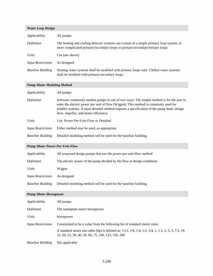
3.246
Water Loop Design
Applicability All pumps
Definition The heating and cooling delivery systems can consist of a simple primary loop system, or more complicated primary/secondary loops or primary/secondary/tertiary loops
Units List (see above)
Input Restrictions As designed
Baseline Building Heating water systems shall be modeled with primary loops only. Chilled water systems shall be modeled with primary/secondary loops.
Pump Motor Modeling Method
Applicability All pumps
Definition Software commonly models pumps in one of two ways: The simple method is for the user to enter the electric power per unit of flow (W/gpm). This method is commonly used for smaller systems. A more detailed method requires a specification of the pump head, design flow, impeller, and motor efficiency.
Units List: Power-Per-Unit-Flow or Detailed
Input Restrictions Either method may be used, as appropriate
Baseline Building Detailed modeling method will be used for the baseline building.
Pump Motor Power-Per-Unit-Flow
Applicability All proposed design pumps that use the power-per-unit-flow method
Definition The electric power of the pump divided by the flow at design conditions
Units W/gpm
Input Restrictions As designed
Baseline Building Detailed modeling method will be used for the baseline building.
Pump Motor Horsepower
Applicability All pumps
Definition The nameplate motor horsepower
Units horsepower
Input Restrictions Constrained to be a value from the following list of standard motor sizes:
A standard motor size table (hp) is defined as: 1/12, 1/8, 1/4, 1/2, 3/4, 1, 1.5, 2, 3, 5, 7.5, 10, 15, 20, 25, 30, 40, 50, 60, 75, 100, 125, 150, 200
Baseline Building Not applicable
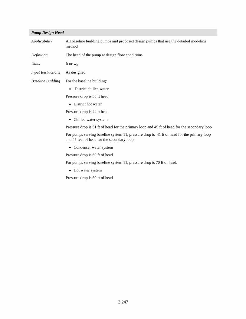
3.247
Pump Design Head
Applicability All baseline building pumps and proposed design pumps that use the detailed modeling method
Definition The head of the pump at design flow conditions
Units ft or wg
Input Restrictions As designed
Baseline Building For the baseline building:
• District chilled water
Pressure drop is 55 ft head
• District hot water
Pressure drop is 44 ft head
• Chilled water system
Pressure drop is 31 ft of head for the primary loop and 45 ft of head for the secondary loop
For pumps serving baseline system 11, pressure drop is 41 ft of head for the primary loop and 45 feet of head for the secondary loop.
• Condenser water system
Pressure drop is 60 ft of head
For pumps serving baseline system 11, pressure drop is 70 ft of head.
• Hot water system
Pressure drop is 60 ft of head
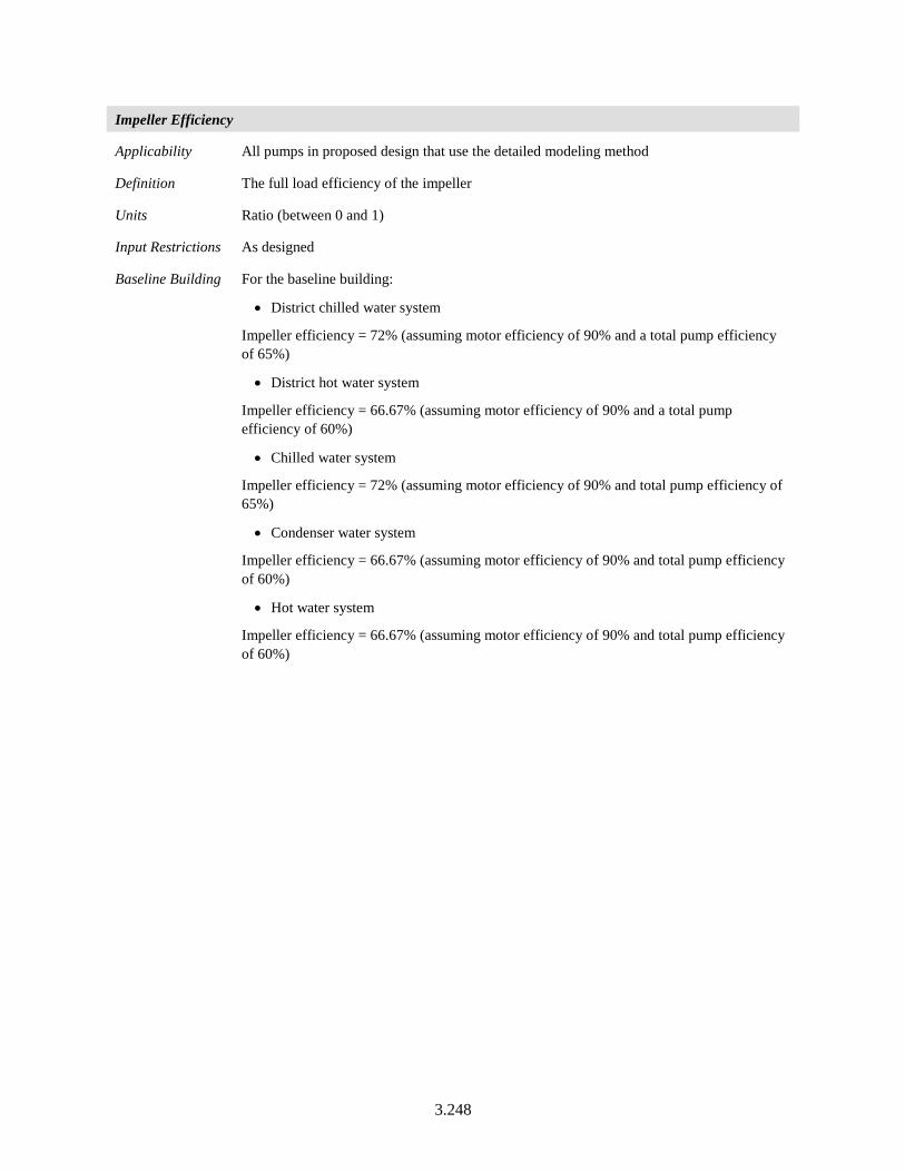
3.248
Impeller Efficiency
Applicability All pumps in proposed design that use the detailed modeling method
Definition The full load efficiency of the impeller
Units Ratio (between 0 and 1)
Input Restrictions As designed
Baseline Building For the baseline building:
• District chilled water system
Impeller efficiency = 72% (assuming motor efficiency of 90% and a total pump efficiency of 65%)
• District hot water system
Impeller efficiency = 66.67% (assuming motor efficiency of 90% and a total pump efficiency of 60%)
• Chilled water system
Impeller efficiency = 72% (assuming motor efficiency of 90% and total pump efficiency of 65%)
• Condenser water system
Impeller efficiency = 66.67% (assuming motor efficiency of 90% and total pump efficiency of 60%)
• Hot water system
Impeller efficiency = 66.67% (assuming motor efficiency of 90% and total pump efficiency of 60%)
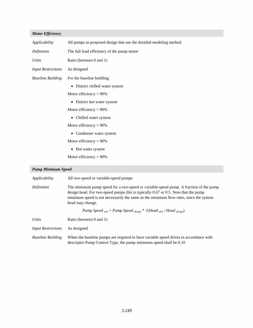
3.249
Motor Efficiency
Applicability All pumps in proposed design that use the detailed modeling method
Definition The full load efficiency of the pump motor
Units Ratio (between 0 and 1)
Input Restrictions As designed
Baseline Building For the baseline building
• District chilled water system
Motor efficiency = 90%
• District hot water system
Motor efficiency = 90%
• Chilled water system
Motor efficiency = 90%
• Condenser water system
Motor efficiency = 90%
• Hot water system
Motor efficiency = 90%
Pump Minimum Speed
Applicability All two-speed or variable-speed pumps
Definition The minimum pump speed for a two-speed or variable-speed pump. A fraction of the pump design head. For two-speed pumps this is typically 0.67 or 0.5. Note that the pump minimum speed is not necessarily the same as the minimum flow ratio, since the system head may change.
Pump Speed min = Pump Speed design * √(Head min / Head design)
Units Ratio (between 0 and 1)
Input Restrictions As designed
Baseline Building When the baseline pumps are required to have variable speed drives in accordance with descriptor Pump Control Type, the pump minimum speed shall be 0.10
3.250
Pump Design Flow (gpm)
Applicability All pumps
Definition The flow rate of the pump at design conditions. For the baseline, this is derived from the heating and cooling loads, the appropriate oversizing factors, and the design supply and return temperatures.
Units gpm or gpm/ton for condenser and primary chilled water pumps
Input Restrictions Not a user input
Baseline Building The temperature change on the evaporator side of the chillers is 12°F (56°F less 44°F) and this equates to a flow of 2 gpm/ton.
The temperature change on the condenser side of the chillers is 10°F, which equates to a flow of 2.4 gpm/ cooling ton. The flow for secondary chilled water varies with cooling demand, since there are two-way valves at the coils. The flow for primary only heating varies with demand down to the minimum required for flow through the boiler. For hot water pumps servicing boilers, the flow rate in gpm shall be the boiler capacity in Btu/h / 25,000, which corresponds to a loop temperature drop of 50°F.
3.251
Pump Control Type
Applicability All pumps
Definition The type of control for the pump. Choices are:
• Fixed speed, fixed flow
• Fixed speed, variable flow (the default, with flow control via a valve)
• Two-speed
• Variable speed, variable flow
Units None
Input Restrictions As designed. The default is “Fixed Speed, Variable Flow,” which models the action of a constant speed pump riding the curve against two-way control valves.
Baseline Building Hot water loops are primary loops only.
• For systems serving less than 120,000 ft2, the HW pump is modeled as variable flow with a constant speed pump riding the pump curve. For systems serving more than 120,000 ft2, the HW pump is modeled as a variable flow with a variable speed pump controlled with a variable speed drive.
Condenser water pumps:
• Condenser water loops are primary only. CW pumps are required to be modeled as fixed speed and fixed flow.
Chilled water pumps:
• The CHW pumping for systems 7, 8, 11, 12, and 13 are primary/secondary with variable flow. The chilled water pumps used for the primary loop are fixed speed and fixed flow.
For systems with a capacity of less than 300 tons, the secondary system pumps shall ride the pump curve.
For systems with a capacity greater than 300 tons, the secondary pumps will be modeled as variable speed.
District chilled water pump shall follow the same rules for secondary chilled water pumps.
3.252
Pump Operation
Applicability All pumps
Definition The type of pump operation can be either on-demand, standby, or scheduled. On-demand operation means the pumps are only pumping when their associated equipment is cycling, so chiller and condenser pumps are on when the chiller is on and the heating hot water pump operates when its associated boiler is cycling. Standby operation allows hot or chilled water to circulate through the primary loop of a primary/secondary loop system or through a reduced portion of a primary-only system, assuming the system has appropriate three-way valves. Scheduled operation means that the pumps and their associated equipment are turned completely off according to occupancy schedules, time of year, or outside conditions. Under scheduled operation, when the systems are on they are assumed to be in On-Demand mode.
Units List: On Demand, Standby, Scheduled
Input Restrictions As designed
Baseline Building The baseline system pumps are assumed to operate in on-demand mode. The chilled water and condenser pumps are tied to the chiller operation, cycling on and off with the chiller, and the heating hot water pumps are tied to the boiler operation.
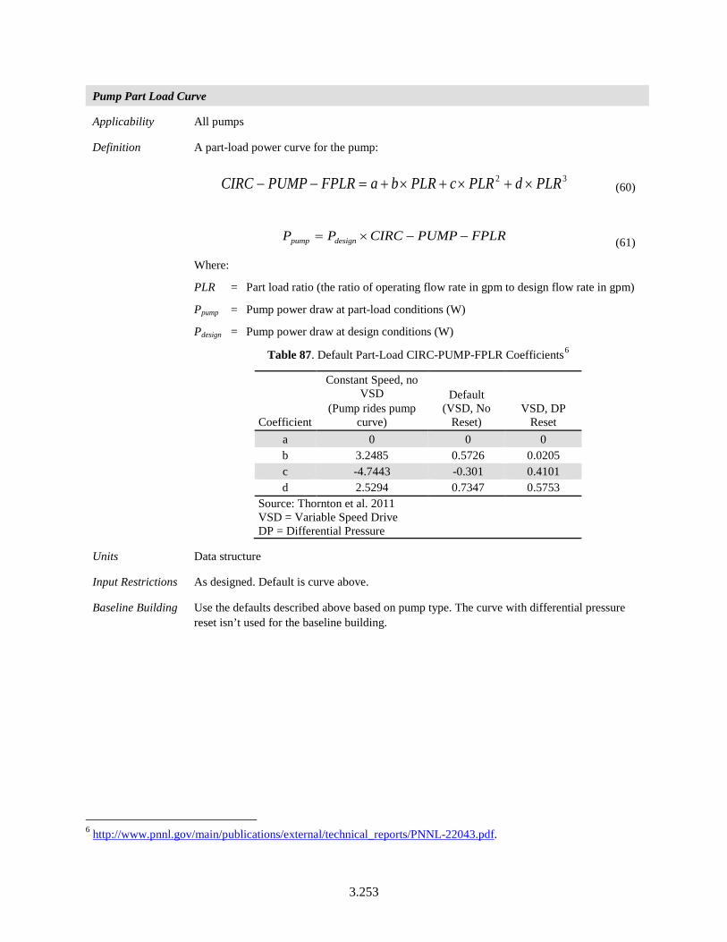
3.253
Pump Part Load Curve
Applicability All pumps
Definition A part-load power curve for the pump:
32 PLRdPLRcPLRbaFPLRPUMPCIRC ×+×+×+=−− (60)
FPLRPUMPCIRCPP designpump −−×= (61)
Where:
PLR = Part load ratio (the ratio of operating flow rate in gpm to design flow rate in gpm)
Ppump = Pump power draw at part-load conditions (W)
Pdesign = Pump power draw at design conditions (W)
Table 87. Default Part-Load CIRC-PUMP-FPLR Coefficients6
Coefficient
Constant Speed, no VSD
(Pump rides pump curve)
Default (VSD, No
Reset) VSD, DP
Reset a 0 0 0 b 3.2485 0.5726 0.0205 c -4.7443 -0.301 0.4101 d 2.5294 0.7347 0.5753
Source: Thornton et al. 2011 VSD = Variable Speed Drive DP = Differential Pressure
Units Data structure
Input Restrictions As designed. Default is curve above.
Baseline Building Use the defaults described above based on pump type. The curve with differential pressure reset isn’t used for the baseline building.
6 http://www.pnnl.gov/main/publications/external/technical_reports/PNNL-22043.pdf.
3.254
3.7.6 Thermal Storage
There are multiple ways to model thermal storage in the proposed design. The baseline building does not have thermal storage.
Storage Type
Applicability All thermal storage systems
Definition A type of thermal energy storage (TES) that indicates the storage medium
Units List
Input Restrictions Ice, chilled water
Baseline Building No thermal storage systems
Configuration
Applicability All thermal storage systems
Definition Indication of how the TES is configured and operated in relation to the chilled water cooling
Units List
Input Restrictions Series, chiller upstream
Series, chiller downstream
Parallel
Baseline Building No thermal storage systems
Ice Storage Type
Applicability All thermal storage systems with storage type = ice
Definition Indication of the storage type for ice storage
Units List, with Options for Internal Melt, External Melt
Input Restrictions Ad designed
Baseline Building No thermal storage systems
Storage Capacity
Applicability All thermal storage systems using ice storage
Definition Nominal storage capacity of the tank
Units Ton-hrs
Input Restrictions None
Baseline Building No thermal storage systems
3.255
Tank Volume
Applicability All thermal storage systems using ice storage
Definition Nominal storage capacity of the tank
Units ft3
Input Restrictions None
Baseline Building No thermal storage systems
CHW Setpoint Schedule
Applicability All thermal storage systems using ice storage
Definition Nominal storage capacity of the tank
Units Series, °F
Input Restrictions None
Baseline Building No thermal storage systems
Deadband Temperature Difference
Applicability All thermal storage systems using chilled water
Definition The deadband temperature difference between enabling and disabling use of the TES system for cooling
Units °F
Input Restrictions None
Baseline Building No thermal storage systems
Maximum Temperature Limit
Applicability All thermal storage systems using chilled water
Definition The minimum allowed temperature of the tank, below which charging of the tank cannot occur
Units °F
Input Restrictions None
Baseline Building No thermal storage systems
3.256
Storage Tank Location Indicator
Applicability All thermal storage systems using ice storage
Definition Nominal storage capacity of the tank
Units List
Input Restrictions Schedule, zone, or exterior
If schedule, the ambient temperature schedule must be specified. If zone, the zone name must be specified.
Baseline Building No thermal storage systems
Storage Tank Heat Gain Coefficient
Applicability All thermal storage systems using chilled water
Definition The heat transfer coefficient between the tank and the ambient surroundings
Units Btu/h-°F
Input Restrictions None
Baseline Building No thermal storage systems
Use Side Heat Transfer Effectiveness
Applicability All thermal storage systems using chilled water
Definition The heat transfer effectiveness between the use side water and the tank water
Units None
Input Restrictions Between 0 and 1
Baseline Building No thermal storage systems
Use Side Design Flow Rate
Applicability All thermal storage systems using chilled water
Definition Design flow rate through the use side of the storage tank
Units gpm
Input Restrictions None
Baseline Building No thermal storage systems
3.257
Source Side Heat Transfer Effectiveness
Applicability All thermal storage systems using chilled water
Definition The heat transfer effectiveness between the source side water and the tank water
Units None
Input Restrictions Between 0 and 1
Baseline Building No thermal storage systems
Source Side Design Flow Rate
Applicability All thermal storage systems using chilled water
Definition Design flow rate through the source side of the storage tank
Units gpm
Input Restrictions None
Baseline Building No thermal storage systems
Tank Recovery Time
Applicability All thermal storage systems using ice storage
Definition This is the time in hours for the tank to cool from 58°F to 48°F. This input is only used if the source side design flow rate is not specified.
Units Hours
Input Restrictions None
Baseline Building No thermal storage systems
3.7.7 Heat Recovery Equipment
Requirements related to exhaust air recovery are documented in Section 3.6.6.6 of this manual.
Heat Recovery Name
Applicability All heat recovery systems
Definition A name assigned to a heat recovery system. This would provide a link to the construction documents.
Units Text, unique
Input Restrictions As designed
Baseline Building Same as proposed
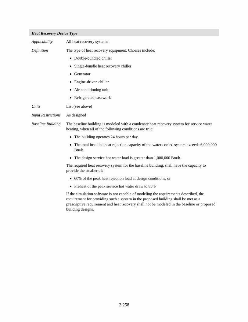
3.258
Heat Recovery Device Type
Applicability All heat recovery systems
Definition The type of heat recovery equipment. Choices include:
• Double-bundled chiller
• Single-bundle heat recovery chiller
• Generator
• Engine-driven chiller
• Air conditioning unit
• Refrigerated casework
Units List (see above)
Input Restrictions As designed
Baseline Building The baseline building is modeled with a condenser heat recovery system for service water heating, when all of the following conditions are true:
• The building operates 24 hours per day.
• The total installed heat rejection capacity of the water cooled system exceeds 6,000,000 Btu/h.
• The design service hot water load is greater than 1,000,000 Btu/h.
The required heat recovery system for the baseline building, shall have the capacity to provide the smaller of:
• 60% of the peak heat rejection load at design conditions, or
• Preheat of the peak service hot water draw to 85°F
If the simulation software is not capable of modeling the requirements described, the requirement for providing such a system in the proposed building shall be met as a prescriptive requirement and heat recovery shall not be modeled in the baseline or proposed building designs.
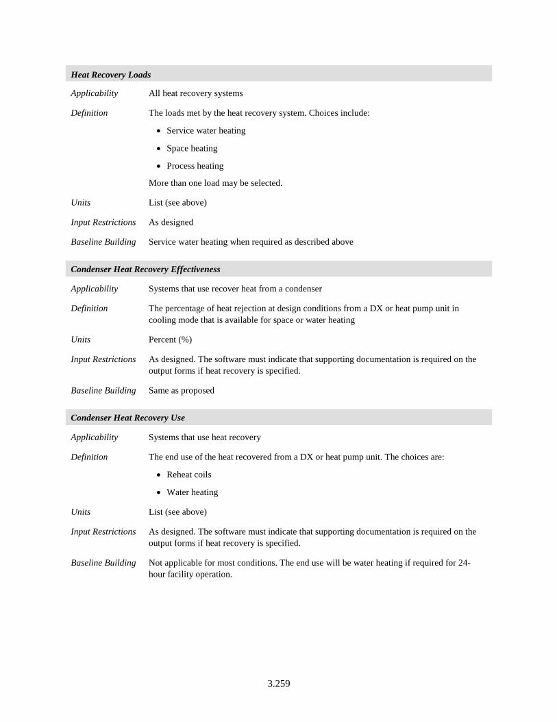
3.259
Heat Recovery Loads
Applicability All heat recovery systems
Definition The loads met by the heat recovery system. Choices include:
• Service water heating
• Space heating
• Process heating
More than one load may be selected.
Units List (see above)
Input Restrictions As designed
Baseline Building Service water heating when required as described above
Condenser Heat Recovery Effectiveness
Applicability Systems that use recover heat from a condenser
Definition The percentage of heat rejection at design conditions from a DX or heat pump unit in cooling mode that is available for space or water heating
Units Percent (%)
Input Restrictions As designed. The software must indicate that supporting documentation is required on the output forms if heat recovery is specified.
Baseline Building Same as proposed
Condenser Heat Recovery Use
Applicability Systems that use heat recovery
Definition The end use of the heat recovered from a DX or heat pump unit. The choices are:
• Reheat coils
• Water heating
Units List (see above)
Input Restrictions As designed. The software must indicate that supporting documentation is required on the output forms if heat recovery is specified.
Baseline Building Not applicable for most conditions. The end use will be water heating if required for 24-hour facility operation.
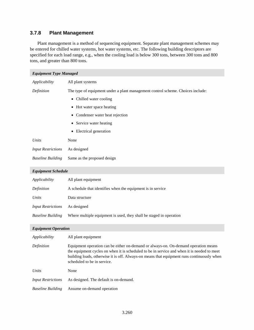
3.260
3.7.8 Plant Management
Plant management is a method of sequencing equipment. Separate plant management schemes may be entered for chilled water systems, hot water systems, etc. The following building descriptors are specified for each load range, e.g., when the cooling load is below 300 tons, between 300 tons and 800 tons, and greater than 800 tons.
Equipment Type Managed
Applicability All plant systems
Definition The type of equipment under a plant management control scheme. Choices include:
• Chilled water cooling
• Hot water space heating
• Condenser water heat rejection
• Service water heating
• Electrical generation
Units None
Input Restrictions As designed
Baseline Building Same as the proposed design
Equipment Schedule
Applicability All plant equipment
Definition A schedule that identifies when the equipment is in service
Units Data structure
Input Restrictions As designed
Baseline Building Where multiple equipment is used, they shall be staged in operation
Equipment Operation
Applicability All plant equipment
Definition Equipment operation can be either on-demand or always-on. On-demand operation means the equipment cycles on when it is scheduled to be in service and when it is needed to meet building loads, otherwise it is off. Always-on means that equipment runs continuously when scheduled to be in service.
Units None
Input Restrictions As designed. The default is on-demand.
Baseline Building Assume on-demand operation
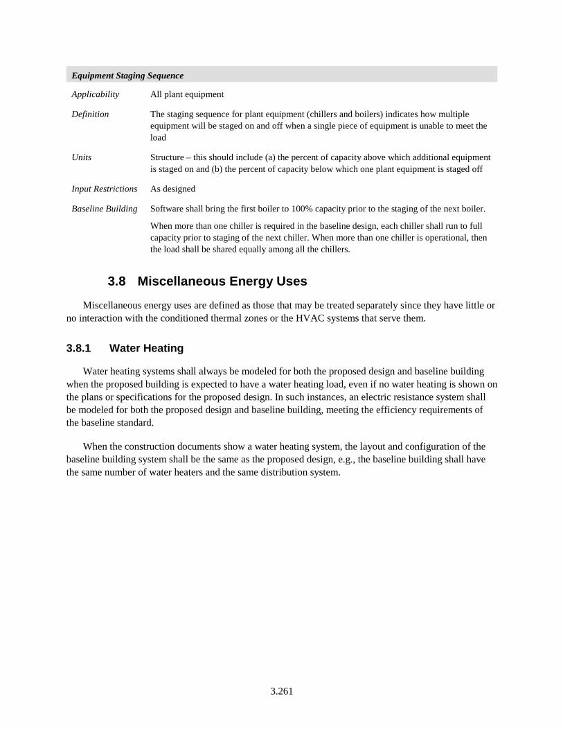
3.261
Equipment Staging Sequence
Applicability All plant equipment
Definition The staging sequence for plant equipment (chillers and boilers) indicates how multiple equipment will be staged on and off when a single piece of equipment is unable to meet the load
Units Structure – this should include (a) the percent of capacity above which additional equipment is staged on and (b) the percent of capacity below which one plant equipment is staged off
Input Restrictions As designed
Baseline Building Software shall bring the first boiler to 100% capacity prior to the staging of the next boiler.
When more than one chiller is required in the baseline design, each chiller shall run to full capacity prior to staging of the next chiller. When more than one chiller is operational, then the load shall be shared equally among all the chillers.
3.8 Miscellaneous Energy Uses
Miscellaneous energy uses are defined as those that may be treated separately since they have little or no interaction with the conditioned thermal zones or the HVAC systems that serve them.
3.8.1 Water Heating
Water heating systems shall always be modeled for both the proposed design and baseline building when the proposed building is expected to have a water heating load, even if no water heating is shown on the plans or specifications for the proposed design. In such instances, an electric resistance system shall be modeled for both the proposed design and baseline building, meeting the efficiency requirements of the baseline standard.
When the construction documents show a water heating system, the layout and configuration of the baseline building system shall be the same as the proposed design, e.g., the baseline building shall have the same number of water heaters and the same distribution system.
3.262
3.8.1.1 System Loads and Configuration
Water Heating System Name
Applicability All water heating systems
Definition A unique descriptor for each water heating system. A system consists of one or more water heaters, a distribution system, an estimate of hot water use, and a schedule for that use. Nonresidential buildings will typically have multiple systems, perhaps a separate electric water heater for each office break room, etc. Other building types such as hotels and hospitals may have a single system serving the entire building.
Units Text, unique
Input Restrictions Where applicable, this should match the tags that are used on the plans such that a plan reviewer can make a connection
Baseline Building The naming convention for the baseline building system shall be similar to the proposed design
Water Heating Peak Use
Applicability All water heating systems, required
Definition An indication of the peak hot water usage (e.g., service to sinks, showers, and kitchen appliances). When specified per occupant, this value is multiplied by design occupancy density values and modified by service water heating schedules to obtain hourly load values that are used in the simulation.
Peak consumption is commonly specified as gallons per hour per occupant, dwelling unit, hotel room, patient room, or floor area. If consumption is specified in gallons per hour, then additional inputs would be needed such as supply temperature, cold water inlet temperature, etc.
It is also common to specify peak use as a thermal load in Btu/h. In the latter case, there is an implied assumption for the cold water inlet temperature, supply temperature, distribution losses, and other factors. The thermal load does not include conversion efficiencies of water heating equipment.
Units Btu/h or gallons/h
Input Restrictions As designed. If these values are not available, the hot water use specified in COMNET Appendix B (COMNET 2017) may be used.
Baseline Building Hot water consumption or load in the baseline building shall be the same as the proposed design, except in cases where:
• A specific measure is specified for the proposed design that will reduce water consumption. Examples of such measures include low-flow terminal devices or controls.
• SHW energy consumption can be demonstrated to be reduced by increasing makeup water temperature or reducing SHW temperature (e.g., alternative sanitizing technologies for dishwashing and heat recovery to entering makeup water).
3.263
• SHW energy consumption can be demonstrated to be reduced by reducing the hot fraction of mixed water. Examples include heat recovery laundry or showers drains.
NOTE: Calculations need to be provided to support the difference in service hot water loads between the proposed and baseline model.
Water Heating Schedule
Applicability All water heating systems
Definition A fractional schedule reflecting the time pattern of water heating use. This input modifies the water heating peak use, described above.
Units Data structure: schedule, fractional
Input Restrictions If known, anticipated schedules shall be used. If not known, the schedules from COMNET Appendix C (COMNET 2017) may be used.
Baseline Building Hot water schedules for the baseline building shall be the same as the proposed design, except in cases where a specific measure is specified for the proposed design that will reduce water consumption and the impact of the measure can be best approximated through an adjustment to the schedule. In general, such measures would be addressed through an adjustment to the water heating, peak use (see above).
Water Heating System Configuration
Applicability All water heating systems
Definition The configuration and layout of the water heating system, including the number of water heaters; the size, location, length, and insulation of distribution pipes; recirculation systems and pumps; and any other details about the system that would affect the energy model
Units Data structure
Input Restrictions None
Baseline Building Same as proposed
Water Mains Temperature Schedule
Applicability All water heating systems
Definition A monthly temperature schedule indicating the water mains temperature. This temperature and the setpoint temperature are used to convert the load into a water flow rate.
Units Data structure: schedule, °F
Input Restrictions Entering water temperature can be defaulted to the values in Table 88 or provided by the user
Baseline Building Same as proposed
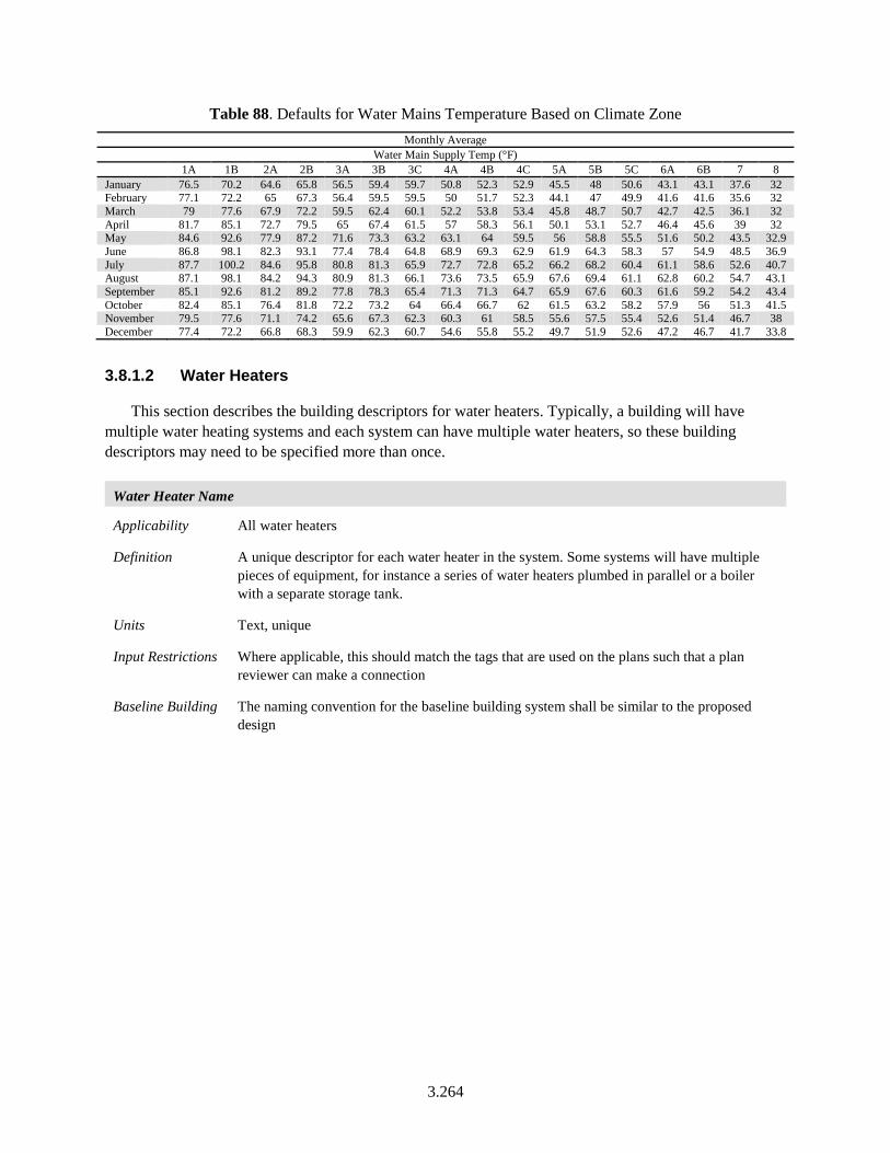
3.264
Table 88. Defaults for Water Mains Temperature Based on Climate Zone Monthly Average
Water Main Supply Temp (°F) 1A 1B 2A 2B 3A 3B 3C 4A 4B 4C 5A 5B 5C 6A 6B 7 8 January 76.5 70.2 64.6 65.8 56.5 59.4 59.7 50.8 52.3 52.9 45.5 48 50.6 43.1 43.1 37.6 32 February 77.1 72.2 65 67.3 56.4 59.5 59.5 50 51.7 52.3 44.1 47 49.9 41.6 41.6 35.6 32 March 79 77.6 67.9 72.2 59.5 62.4 60.1 52.2 53.8 53.4 45.8 48.7 50.7 42.7 42.5 36.1 32 April 81.7 85.1 72.7 79.5 65 67.4 61.5 57 58.3 56.1 50.1 53.1 52.7 46.4 45.6 39 32 May 84.6 92.6 77.9 87.2 71.6 73.3 63.2 63.1 64 59.5 56 58.8 55.5 51.6 50.2 43.5 32.9 June 86.8 98.1 82.3 93.1 77.4 78.4 64.8 68.9 69.3 62.9 61.9 64.3 58.3 57 54.9 48.5 36.9 July 87.7 100.2 84.6 95.8 80.8 81.3 65.9 72.7 72.8 65.2 66.2 68.2 60.4 61.1 58.6 52.6 40.7 August 87.1 98.1 84.2 94.3 80.9 81.3 66.1 73.6 73.5 65.9 67.6 69.4 61.1 62.8 60.2 54.7 43.1 September 85.1 92.6 81.2 89.2 77.8 78.3 65.4 71.3 71.3 64.7 65.9 67.6 60.3 61.6 59.2 54.2 43.4 October 82.4 85.1 76.4 81.8 72.2 73.2 64 66.4 66.7 62 61.5 63.2 58.2 57.9 56 51.3 41.5 November 79.5 77.6 71.1 74.2 65.6 67.3 62.3 60.3 61 58.5 55.6 57.5 55.4 52.6 51.4 46.7 38 December 77.4 72.2 66.8 68.3 59.9 62.3 60.7 54.6 55.8 55.2 49.7 51.9 52.6 47.2 46.7 41.7 33.8
3.8.1.2 Water Heaters
This section describes the building descriptors for water heaters. Typically, a building will have multiple water heating systems and each system can have multiple water heaters, so these building descriptors may need to be specified more than once.
Water Heater Name
Applicability All water heaters
Definition A unique descriptor for each water heater in the system. Some systems will have multiple pieces of equipment, for instance a series of water heaters plumbed in parallel or a boiler with a separate storage tank.
Units Text, unique
Input Restrictions Where applicable, this should match the tags that are used on the plans such that a plan reviewer can make a connection
Baseline Building The naming convention for the baseline building system shall be similar to the proposed design
3.265
Water Heater Type and Size
Applicability All water heaters
Definition This building descriptor includes information needed to determine the criteria from baseline standards. The choices are listed below.
• Electric water heaters (storage and instantaneous)
Small (≤ 12 kW)
Large (> 12 kW)
Heat pump
• Gas storage water heaters
Small (≤ 75,000 Btu/h)
Large (> 75,000 Btu/h)
• Gas instantaneous water heaters
Small (> 50,000 and < 200,000 Btu/h)
Large (≥ 200,000 Btu/h), <10 gal
Large (≥ 200,000 Btu/h), >= 10 gal
• Oil storage water heaters
Small (≤ 105,000 Btu/h)
Large (> 105,000 Btu/h)
• Oil instantaneous water heaters
Small (≤ 210,000 Btu/h)
Large (> 210,000 Btu/h), <10 gal
Large (> 210,000 Btu/h), >= 10 gal
• Gas hot water supply boiler
• Oil hot water supply boiler
• Heat exchanger from steam or district hot water
Units List (see above)
Input Restrictions The water heater type shall agree with equipment specified in the construction documents.
If no service hot water system exists or has been specified, but the building will have service hot water loads, a service water system using electric resistance heat shall be assumed.
For buildings that will have no service hot water load, no service water heating system shall be modeled.
Baseline Building Water heaters in the baseline system will be based on the building area type classification. See Table 89 below.
For new service hot water systems, the system will be sized according to the provisions of Standard 90.1-2016, Section 7.4.1, and the equipment shall match the minimum efficiency
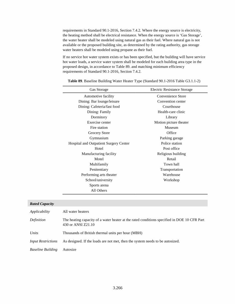
3.266
requirements in Standard 90.1-2016, Section 7.4.2. Where the energy source is electricity, the heating method shall be electrical resistance. When the energy source is ‘Gas Storage’, the water heater shall be modeled using natural gas as their fuel. Where natural gas is not available or the proposed building site, as determined by the rating authority, gas storage water heaters shall be modeled using propane as their fuel.
If no service hot water system exists or has been specified, but the building will have service hot water loads, a service water system shall be modeled for each building area type in the proposed design, in accordance to Table 89. and matching minimum efficiency requirements of Standard 90.1-2016, Section 7.4.2.
Table 89. Baseline Building Water Heater Type (Standard 90.1-2016 Table G3.1.1-2)
Gas Storage Electric Resistance Storage
Automotive facility Dining: Bar lounge/leisure Dining: Cafeteria/fast food
Dining: Family Dormitory
Exercise center Fire station
Grocery Store Gymnasium
Hospital and Outpatient Surgery Center Hotel
Manufacturing facility Motel
Multifamily Penitentiary
Performing arts theater School/university
Sports arena All Others
Convenience Store Convention center
Courthouse Health-care clinic
Library Motion picture theater
Museum Office
Parking garage Police station
Post office Religious building
Retail Town hall
Transportation Warehouse Workshop
Rated Capacity
Applicability All water heaters
Definition The heating capacity of a water heater at the rated conditions specified in DOE 10 CFR Part 430 or ANSI Z21.10
Units Thousands of British thermal units per hour (MBH)
Input Restrictions As designed. If the loads are not met, then the system needs to be autosized.
Baseline Building Autosize
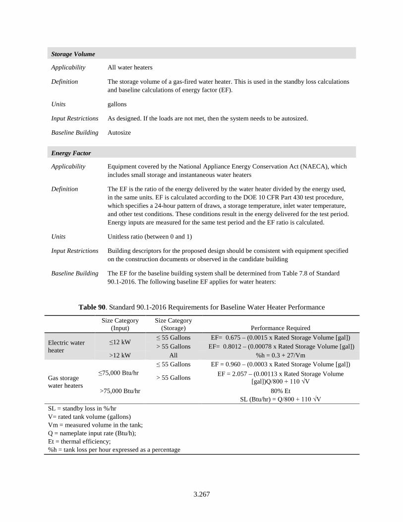
3.267
Storage Volume
Applicability All water heaters
Definition The storage volume of a gas-fired water heater. This is used in the standby loss calculations and baseline calculations of energy factor (EF).
Units gallons
Input Restrictions As designed. If the loads are not met, then the system needs to be autosized.
Baseline Building Autosize
Energy Factor
Applicability Equipment covered by the National Appliance Energy Conservation Act (NAECA), which includes small storage and instantaneous water heaters
Definition The EF is the ratio of the energy delivered by the water heater divided by the energy used, in the same units. EF is calculated according to the DOE 10 CFR Part 430 test procedure, which specifies a 24-hour pattern of draws, a storage temperature, inlet water temperature, and other test conditions. These conditions result in the energy delivered for the test period. Energy inputs are measured for the same test period and the EF ratio is calculated.
Units Unitless ratio (between 0 and 1)
Input Restrictions Building descriptors for the proposed design should be consistent with equipment specified on the construction documents or observed in the candidate building
Baseline Building The EF for the baseline building system shall be determined from Table 7.8 of Standard 90.1-2016. The following baseline EF applies for water heaters:
Table 90. Standard 90.1-2016 Requirements for Baseline Water Heater Performance
Size Category
(Input) Size Category
(Storage) Performance Required
Electric water heater
≤12 kW ≤ 55 Gallons EF= 0.675 – (0.0015 x Rated Storage Volume [gal]) > 55 Gallons EF= 0.8012 – (0.00078 x Rated Storage Volume [gal])
>12 kW All %h = 0.3 + 27/Vm
Gas storage water heaters
≤75,000 Btu/hr ≤ 55 Gallons EF = 0.960 – (0.0003 x Rated Storage Volume [gal])
> 55 Gallons EF = 2.057 – (0.00113 x Rated Storage Volume [gal])Q/800 + 110 √V
>75,000 Btu/hr
80% Et SL (Btu/hr) = Q/800 + 110 √V
SL = standby loss in %/hr V= rated tank volume (gallons) Vm = measured volume in the tank; Q = nameplate input rate (Btu/h); Et = thermal efficiency; %h = tank loss per hour expressed as a percentage
3.268
Thermal Efficiency
Applicability Oil and gas-fired water heaters not covered by NAECA
Definition The full load efficiency of a water heater at rated conditions expressed as a dimensionless ratio of output over input
Units Unitless ratio (between 0 and 1)
Input Restrictions Building descriptors for the proposed design should be consistent with equipment specified on the construction documents or observed in the candidate building
Baseline Building From Table 7.8 of Standard 90.1-2016, also documented in Table 90.
Tank Standby Loss
Applicability Water heaters not covered by NAECA
Definition The tank standby loss for storage tanks, which includes the effect of recovery efficiency
Units Btu/h for the entire tank
Input Restrictions As specified in manufacturer data and documented on the construction documents
Baseline Building As specified in Table 7.8 of Standard 90.1-2016, also documented in Table 90
Tank Off-Cycle Loss Coefficient
Applicability Water heaters
Definition The tank standby loss coefficient (UA) for the water heater. For small water heaters covered by NAECA, the loss coefficient is a derived parameter, a function of the energy factor and recovery efficiency.
Units Btu/h-°F
Input Restrictions For NAECA covered water heaters, the loss coefficient is calculated by the following:
)141094
24(5.67
/1/1
PonRE
REEFUA
⋅−×
−=
Where:
EF = The energy factor of the rated water heater (unitless)
RE = The recovery efficiency of the rated water heater. If this data is not available, the default shall be 0.78 for gas water heaters and 0.93 for electric water heaters.
Pon = The input power to the water heater, in Btu/h
Baseline Building The baseline loss coefficient for NAECA water heaters shall be:
10 Btu/h-°F for gas-fired water heaters
3.269
Off Cycle Parasitic Losses
Applicability Water heater
Definition The rate of parasitic losses, such as a pilot light or controls, when the water heater is not heating. If modeled explicitly, pilot lights should contribute to off-cycle heating.
Units Watts
Input Restrictions As designed
Baseline Building 0
Off Cycle Fuel Type
Applicability Water heater
Definition The type of fuel that serves energy using parasitic equipment, such as a pilot light or controls, when the water heater is not heating
Units List: Electricity, Gas, Oil, Propane
Input Restrictions As designed
Baseline Building Not applicable
On Cycle Parasitic Losses
Applicability Water heater
Definition The rate of parasitic losses, such as a pilot light or draft fan controls, when the water heater is heating. This may be different than off cycle losses if the flue energy is considered.
Units Watts
Input Restrictions As designed
Baseline Building 0
On Cycle Fuel Type
Applicability Water heater
Definition The type of fuel that serves energy using parasitic equipment, such as a pilot light or controls, when the water heater is not heating
Units List: Electricity, Gas, Oil, Propane
Input Restrictions As designed
Baseline Building Not applicable
3.270
Water Heater Ambient Temperature Indicator
Applicability Water heater
Definition The location of the water heater for determining losses and energy interaction with the surroundings
Units List: Schedule, Zone, Outdoors
Input Restrictions As designed. When “Schedule” is used, a time of day schedule needs to be specified with temperature schedule for each hour.
Baseline Building Same as proposed
Fuel Water Heater Part Load Efficiency Curve
Applicability Water heating equipment for which a thermal efficiency as opposed to an EF is specified
Definition A set of factors that adjust the full-load thermal efficiency for part load conditions. The factor is set as a curve.
Units Percent (%)
Input Restrictions The following default curve shall be used unless detailed information is provided to justify alternative values. The default curve shall take the form of a quadratic equation as follows:
×+×+=
×=
2
rated
partload
rated
partload
designpartload
cQ
QbaFHeatPLC
FHeatPLCFuelFuel
(62)
Where:
FHeatPLC = The fuel heating part load efficiency curve
Fuelpartload = The fuel consumption at part load conditions (Btu/h)
Fuel design = The fuel consumption at design conditions (Btu/h)
Qpartload = The water heater capacity at part load conditions (Btu/h)
Qrated = The water heater capacity at design conditions (Btu/h)
a = Constant, 0.021826
b = Constant, 0.977630
c = Constant, 0.000543
Baseline Building The baseline shall use the default curve
3.271
3.8.1.3 Recirculation Systems
This section describes the building descriptors for hot water recirculation systems. The baseline building has a recirculation system when the proposed design does. This is one aspect of the water heating system configuration (see above).
Recirculation System Name
Applicability All recirculation systems
Definition A unique descriptor for each water heating recirculation system
Units Text, unique
Input Restrictions Where applicable, this should match the tags or descriptions that are used on plans such that a plan reviewer can make a connection
Baseline Building The naming convention of the baseline building shall be similar to the proposed design
Pumping Power
Applicability All recirculation systems
Definition The electric demand of the pumps when the recirculation system is operating. This input is a function of the flow rate, the pumping head, the motor efficiency, and the pump efficiency. Some software may allow each of these factors to be separately entered.
Units Watts (W)
Input Restrictions Pumping power shall be consistent with the piping configuration, flow rate, and equipment specified on the construction documents
Baseline Building Pumping power in the baseline building shall be the same as the proposed design unless specific measures are included in the proposed design to reduce the pumping power. Example measures could include reducing pumping head by oversizing distribution piping or specifying premium efficiency motors or pumps.
Schedule
Applicability All recirculation systems
Definition An on/off or fraction schedule that indicates when the recirculation system is expected to be operated
Units Data structure: schedule, on/off or fraction
Input Restrictions The schedule for operation of the recirculation system shall be consistent with the design intent of the system. Hotels, hospitals, and other 24x7 institutional buildings will typically have a system that runs continuously. The schedule should be consistent with the controls called for on the construction documents: no control (runs constantly), timer control, temperature control, timer/temperature control, or demand control.
Baseline Building Recirculation schedules for the baseline building shall be the same as the proposed design
3.272
Piping
Applicability All recirculation systems
Definition The heat loss rate of piping for recirculating systems. This may be defined separately for pipe that is exposed to outdoor conditions, indoor or semi-heated conditions, or buried underground conditions. These losses may be modeled as additional loads on the water heater(s).
Units Btu/h-°F specified separately for outdoor, indoor, or buried locations
Input Restrictions In accordance with Standard 90.1-2016, Section G3.1.3.6, piping heat losses are not modeled for the proposed building
Baseline Building Same as proposed
3.8.1.4 Water Heating Auxiliaries
External Storage Tank Insulation
Applicability All water heating systems that have an external storage tank
Definition Some water heating systems have a storage tank that is separate from the water heater(s) that provides additional storage capacity. This building descriptor addresses the heat loss related to the external tank, which is an additional load that must be satisfied by the water heater(s).
Units R-value (h-ft2-°F/Btu)
Input Restrictions As specified in manufacturer data and documented on the construction documents
Baseline Building Heat loss associated with the storage tank in the baseline building shall meet the requirements for an unfired storage tank in the baseline standards (Standard 90.1-2016, Table 7.8), which is an insulation R-value of 12.5. The surface area and location of the storage tank shall be the same as the proposed design.
External Storage Tank Area
Applicability All water heating systems that have an external storage tank
Definition Some water heating systems have a storage tank that is separate from the water heater(s) that provides additional storage capacity. This documents the entire exterior surface area of the tank.
Units ft2
Input Restrictions As specified in manufacturer specifications
Baseline Building Same as proposed
3.273
External Storage Tank Location
Applicability All water heating systems that have an external storage tank
Definition Location of the storage tank, used to determine the heat loss rate and energy exchange with the surroundings
Units List: Schedule, Zone, Outdoors
Input Restrictions As designed
Baseline Building Same as proposed
Heat Recovery
Applicability Water heating systems that are coupled to heat recovery equipment
Definition Building equipment such as air conditioners, chillers, gas-fired generators, and others produce thermal energy that may be recovered and used to heat water. The heat-producing characteristics are generally defined for the equipment that is producing the heat, not the equipment that is receiving the heat (water heaters in this case). The building descriptors will vary depending on the equipment. The models for heat-producing equipment need to produce output hourly so that the schedule of heat production and heating needs can be aligned and evaluated in the water heating model.
Units Data structure: depends on the equipment producing the heat
Input Restrictions There are no restrictions, other than agreement with the construction documents
Baseline Building The baseline building requirements for condenser heat recovery are documented in Section 3.7.7 of this manual
3.274
Solar Thermal
Applicability Water heating systems with a solar thermal system
Definition A solar thermal water heating system consists of one or more collectors. Water is passed through these collectors and is heated under the right conditions. There are two general types of solar water heaters: integrated collector storage (ICS) systems and active systems. Active systems include pumps to circulate the water, storage tanks, piping, and controls. ICS systems generally have no pumps and piping is minimal.
Solar systems may be tested and rated as a complete system or the collectors may be separately tested and rated. SRCC OG-300 is the test procedure for whole systems and SRCC OG-100 is the test procedure for collectors. The building descriptors used to define the solar thermal system may vary with each software application and with the details of system design.
The solar fraction shall be estimated by the f-chart procedure for solar water heating systems.
Units Data structure: will vary with the software and system details
Input Restrictions As designed. The proposed design may have a combined space and water heating system.
Baseline Building Not applicable
Combined Space Heating and Water Heating
Applicability Projects that use a boiler to provide both space heat and water heating
Definition A system that provides both space heating and water heating from the same equipment, generally the space heating boiler. Such systems are restricted by the baseline standards, but may be modeled in the candidate building. The restrictions are due to the misalignment of the space heating load and the water heating load. The first is highly intermittent and weather dependent, while the latter is more constant and not generally related to the weather.
Units Data structure
Input Restrictions As designed. The proposed design may have a combined space and water heating system.
Baseline Building The baseline building shall be modeled with separate space heating and water heating systems, meeting the prescriptive requirements for each. The water heating system shall use the same fuel as the combined boiler.
3.275
3.8.2 Swimming Pools
Swimming pools must meet applicable mandatory requirements mentioned in the sections below.
Pool Name
Applicability All pools
Definition A unique identifier that keys the pool to the construction documents
Units Text, unique
Input Restrictions None
Baseline Building The name for the baseline building pool should be similar to the proposed design
Volume
Applicability All pools
Definition The volume of the pool
Units Cubic feet (ft3)
Input Restrictions None
Baseline Building Same as proposed
Surface Area
Applicability All pools
Definition The surface area of the pool affects heat loss and evaporation
Units Square feet (ft2)
Input Restrictions None
Baseline Building Same as proposed
Cover
Applicability All pools
Definition An indication
Units Boolean (yes/no)
Input Restrictions As designed. Pool covers are required for heated pools in accordance with Standard 90.1-2016 Section 7.4.5.2.
Baseline Building Pool should be covered when the space is unoccupied
3.276
Cover Schedule
Applicability All pools
Definition A schedule indicating when the pool cover is in place
Units Data structure: schedule, on/off or fractional
Input Restrictions None
Baseline Building Same as proposed
Filtration Rate
Applicability All pools
Definition The rate at which the pool water is passed through the filtering system when the filtration system is operating
Units Hours per pool change
Input Restrictions None
Baseline Building Same as proposed
Filtration Schedule
Applicability All pools
Definition A schedule indicating when the pool filtration system is in operation
Units Data structure: schedule, on/off or fractional
Input Restrictions None
Baseline Building Same as proposed
Temperature
Applicability All pools
Definition Temperature at which the pool is maintained
Units Degrees Fahrenheit (°F)
Input Restrictions None
Baseline Building Same as proposed
3.277
Temperature Schedule
Applicability All pools
Definition A schedule indicating variation in the pool temperature, either seasonally or monthly
Units Data structure: schedule, temperature
Input Restrictions None
Baseline Building Same as proposed
Pumping and Filtration: Pumping Power
Applicability All pools
Definition The power used by the pumping system. This is a function of the pumping head (which depends on pipe lengths, sizes, and filtration type), the pump efficiency, the motor efficiency, and the flow rate. Some software may allow these to be entered as separate building descriptors. This value should be consistent with the filtration rate noted above.
Units Watts (W)
Input Restrictions As designed
Baseline Building Same as the proposed design unless the proposed design uses special low head filters and premium efficiency motors
Heating Equipment: Heater Type
Applicability All pools
Definition The type of equipment that is used to maintain the pool temperature
Units List: Solar, Heat Pump, Gas, Oil, or Electric Resistance
Input Restrictions None
Baseline Building If there is gas or oil on the site, the baseline building shall be modeled with a natural gas or oil pool heater meeting the requirements of Table 7.8 of Standard 90.1-2016. If there is no gas or oil on the site, the baseline building shall be modeled with a heat pump pool heater meeting the requirements of Table 7.8 of Standard 90.1-2016.
Heating Equipment: Heater Efficiency
Applicability All pools with heaters
Definition The thermal efficiency of the pool heater
Units Unitless, thermal efficiency
Input Restrictions None
Baseline Building See the baseline rules for heater type
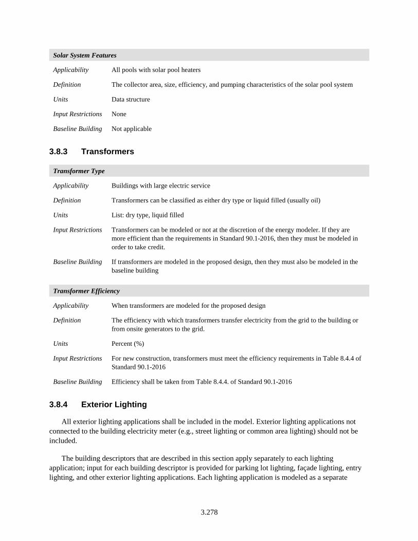
3.278
Solar System Features
Applicability All pools with solar pool heaters
Definition The collector area, size, efficiency, and pumping characteristics of the solar pool system
Units Data structure
Input Restrictions None
Baseline Building Not applicable
3.8.3 Transformers
Transformer Type
Applicability Buildings with large electric service
Definition Transformers can be classified as either dry type or liquid filled (usually oil)
Units List: dry type, liquid filled
Input Restrictions Transformers can be modeled or not at the discretion of the energy modeler. If they are more efficient than the requirements in Standard 90.1-2016, then they must be modeled in order to take credit.
Baseline Building If transformers are modeled in the proposed design, then they must also be modeled in the baseline building
Transformer Efficiency
Applicability When transformers are modeled for the proposed design
Definition The efficiency with which transformers transfer electricity from the grid to the building or from onsite generators to the grid.
Units Percent (%)
Input Restrictions For new construction, transformers must meet the efficiency requirements in Table 8.4.4 of Standard 90.1-2016
Baseline Building Efficiency shall be taken from Table 8.4.4. of Standard 90.1-2016
3.8.4 Exterior Lighting
All exterior lighting applications shall be included in the model. Exterior lighting applications not connected to the building electricity meter (e.g., street lighting or common area lighting) should not be included.
The building descriptors that are described in this section apply separately to each lighting application; input for each building descriptor is provided for parking lot lighting, façade lighting, entry lighting, and other exterior lighting applications. Each lighting application is modeled as a separate
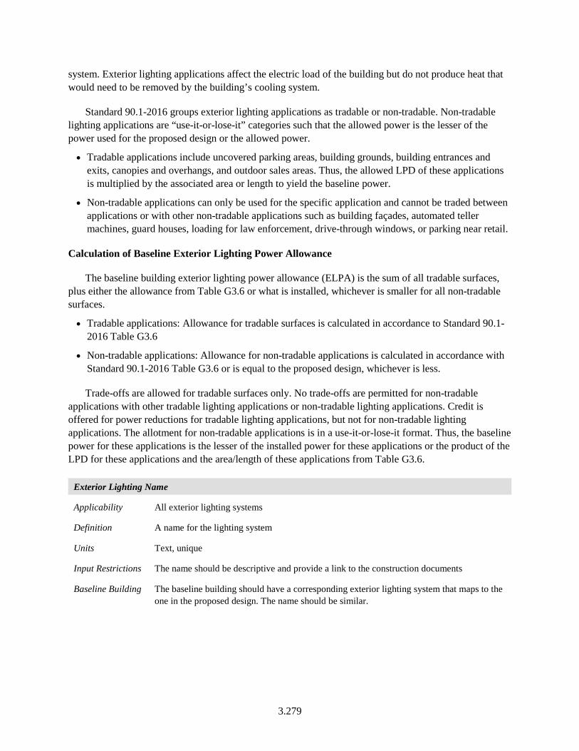
3.279
system. Exterior lighting applications affect the electric load of the building but do not produce heat that would need to be removed by the building’s cooling system.
Standard 90.1-2016 groups exterior lighting applications as tradable or non-tradable. Non-tradable lighting applications are “use-it-or-lose-it” categories such that the allowed power is the lesser of the power used for the proposed design or the allowed power.
• Tradable applications include uncovered parking areas, building grounds, building entrances and exits, canopies and overhangs, and outdoor sales areas. Thus, the allowed LPD of these applications is multiplied by the associated area or length to yield the baseline power.
• Non-tradable applications can only be used for the specific application and cannot be traded between applications or with other non-tradable applications such as building façades, automated teller machines, guard houses, loading for law enforcement, drive-through windows, or parking near retail.
Calculation of Baseline Exterior Lighting Power Allowance
The baseline building exterior lighting power allowance (ELPA) is the sum of all tradable surfaces, plus either the allowance from Table G3.6 or what is installed, whichever is smaller for all non-tradable surfaces.
• Tradable applications: Allowance for tradable surfaces is calculated in accordance to Standard 90.1-2016 Table G3.6
• Non-tradable applications: Allowance for non-tradable applications is calculated in accordance with Standard 90.1-2016 Table G3.6 or is equal to the proposed design, whichever is less.
Trade-offs are allowed for tradable surfaces only. No trade-offs are permitted for non-tradable applications with other tradable lighting applications or non-tradable lighting applications. Credit is offered for power reductions for tradable lighting applications, but not for non-tradable lighting applications. The allotment for non-tradable applications is in a use-it-or-lose-it format. Thus, the baseline power for these applications is the lesser of the installed power for these applications or the product of the LPD for these applications and the area/length of these applications from Table G3.6.
Exterior Lighting Name
Applicability All exterior lighting systems
Definition A name for the lighting system
Units Text, unique
Input Restrictions The name should be descriptive and provide a link to the construction documents
Baseline Building The baseline building should have a corresponding exterior lighting system that maps to the one in the proposed design. The name should be similar.
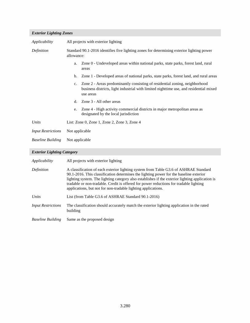
3.280
Exterior Lighting Zones
Applicability All projects with exterior lighting
Definition Standard 90.1-2016 identifies five lighting zones for determining exterior lighting power allowance:
a. Zone 0 - Undeveloped areas within national parks, state parks, forest land, rural areas
b. Zone 1 - Developed areas of national parks, state parks, forest land, and rural areas
c. Zone 2 - Areas predominantly consisting of residential zoning, neighborhood business districts, light industrial with limited nighttime use, and residential mixed use areas
d. Zone 3 - All other areas
e. Zone 4 - High activity commercial districts in major metropolitan areas as designated by the local jurisdiction
Units List: Zone 0, Zone 1, Zone 2, Zone 3, Zone 4
Input Restrictions Not applicable
Baseline Building Not applicable
Exterior Lighting Category
Applicability All projects with exterior lighting
Definition A classification of each exterior lighting system from Table G3.6 of ASHRAE Standard 90.1-2016. This classification determines the lighting power for the baseline exterior lighting system. The lighting category also establishes if the exterior lighting application is tradable or non-tradable. Credit is offered for power reductions for tradable lighting applications, but not for non-tradable lighting applications.
Units List (from Table G3.6 of ASHRAE Standard 90.1-2016)
Input Restrictions The classification should accurately match the exterior lighting application in the rated building
Baseline Building Same as the proposed design
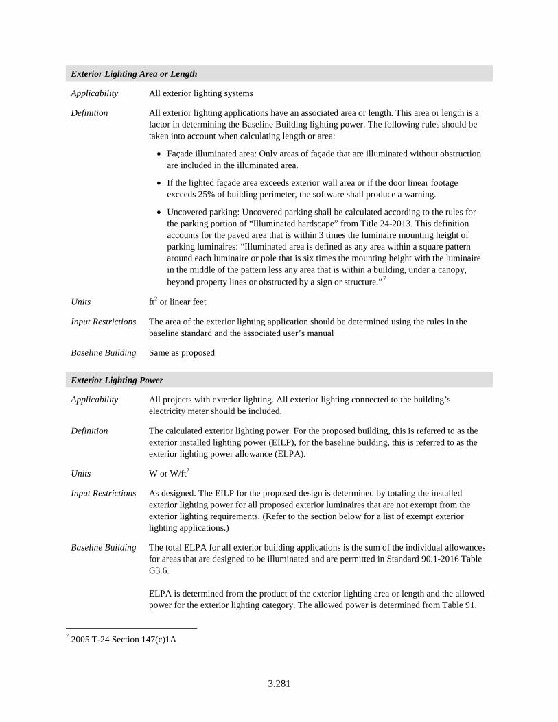
3.281
Exterior Lighting Area or Length
Applicability All exterior lighting systems
Definition All exterior lighting applications have an associated area or length. This area or length is a factor in determining the Baseline Building lighting power. The following rules should be taken into account when calculating length or area:
• Façade illuminated area: Only areas of façade that are illuminated without obstruction are included in the illuminated area.
• If the lighted façade area exceeds exterior wall area or if the door linear footage exceeds 25% of building perimeter, the software shall produce a warning.
• Uncovered parking: Uncovered parking shall be calculated according to the rules for the parking portion of “Illuminated hardscape” from Title 24-2013. This definition accounts for the paved area that is within 3 times the luminaire mounting height of parking luminaires: “Illuminated area is defined as any area within a square pattern around each luminaire or pole that is six times the mounting height with the luminaire in the middle of the pattern less any area that is within a building, under a canopy, beyond property lines or obstructed by a sign or structure.”7
Units ft2 or linear feet
Input Restrictions The area of the exterior lighting application should be determined using the rules in the baseline standard and the associated user’s manual
Baseline Building Same as proposed
Exterior Lighting Power
Applicability All projects with exterior lighting. All exterior lighting connected to the building’s electricity meter should be included.
Definition The calculated exterior lighting power. For the proposed building, this is referred to as the exterior installed lighting power (EILP), for the baseline building, this is referred to as the exterior lighting power allowance (ELPA).
Units W or W/ft2
Input Restrictions As designed. The EILP for the proposed design is determined by totaling the installed exterior lighting power for all proposed exterior luminaires that are not exempt from the exterior lighting requirements. (Refer to the section below for a list of exempt exterior lighting applications.)
Baseline Building The total ELPA for all exterior building applications is the sum of the individual allowances for areas that are designed to be illuminated and are permitted in Standard 90.1-2016 Table G3.6. ELPA is determined from the product of the exterior lighting area or length and the allowed power for the exterior lighting category. The allowed power is determined from Table 91.
7 2005 T-24 Section 147(c)1A
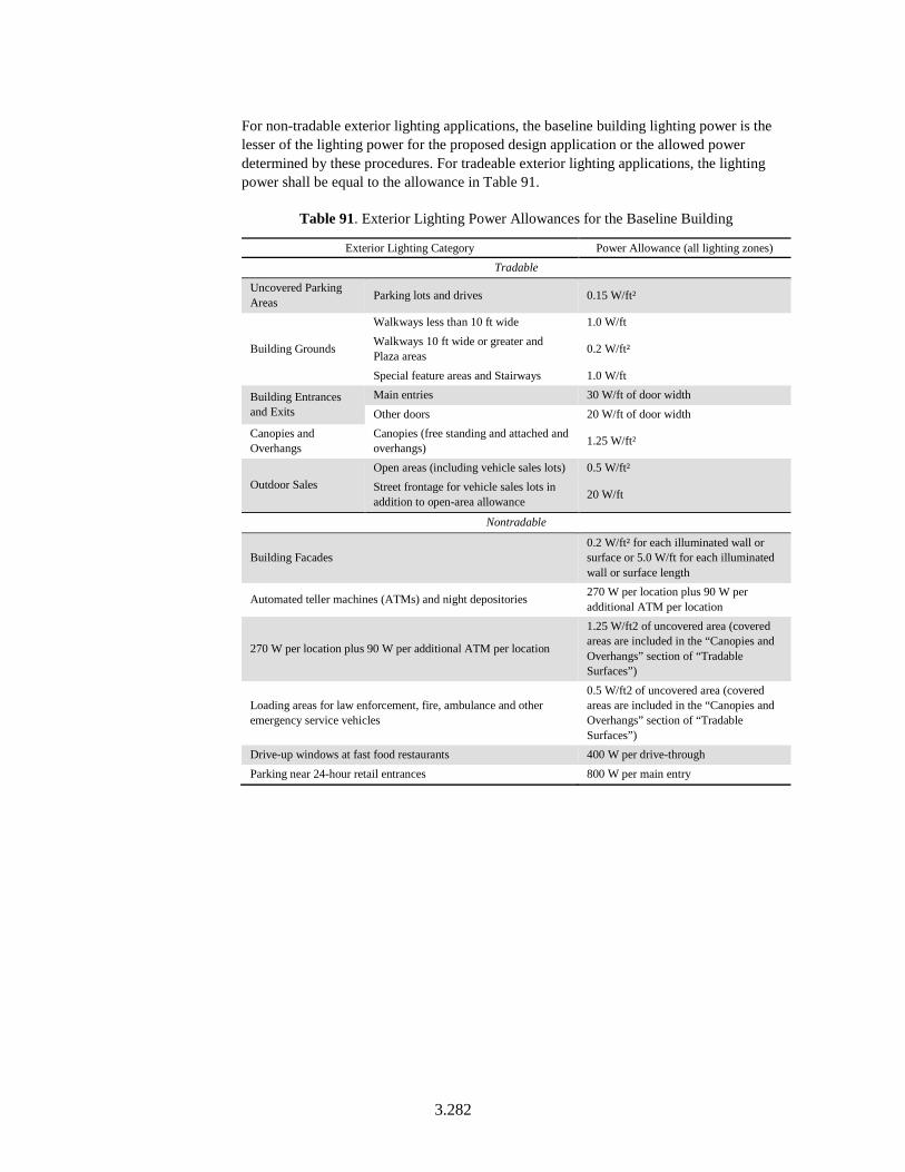
3.282
For non-tradable exterior lighting applications, the baseline building lighting power is the lesser of the lighting power for the proposed design application or the allowed power determined by these procedures. For tradeable exterior lighting applications, the lighting power shall be equal to the allowance in Table 91.
Table 91. Exterior Lighting Power Allowances for the Baseline Building
Exterior Lighting Category Power Allowance (all lighting zones) Tradable
Uncovered Parking Areas Parking lots and drives 0.15 W/ft²
Building Grounds
Walkways less than 10 ft wide 1.0 W/ft Walkways 10 ft wide or greater and Plaza areas 0.2 W/ft²
Special feature areas and Stairways 1.0 W/ft
Building Entrances and Exits
Main entries 30 W/ft of door width Other doors 20 W/ft of door width
Canopies and Overhangs
Canopies (free standing and attached and overhangs) 1.25 W/ft²
Outdoor Sales Open areas (including vehicle sales lots) 0.5 W/ft² Street frontage for vehicle sales lots in addition to open-area allowance 20 W/ft
Nontradable
Building Facades 0.2 W/ft² for each illuminated wall or surface or 5.0 W/ft for each illuminated wall or surface length
Automated teller machines (ATMs) and night depositories 270 W per location plus 90 W per additional ATM per location
270 W per location plus 90 W per additional ATM per location
1.25 W/ft2 of uncovered area (covered areas are included in the “Canopies and Overhangs” section of “Tradable Surfaces”)
Loading areas for law enforcement, fire, ambulance and other emergency service vehicles
0.5 W/ft2 of uncovered area (covered areas are included in the “Canopies and Overhangs” section of “Tradable Surfaces”)
Drive-up windows at fast food restaurants 400 W per drive-through Parking near 24-hour retail entrances 800 W per main entry
3.283
Non-Regulated Exterior Lighting Power Allowance
Applicability All projects with exterior lighting
Definition Lighting used for the following exterior applications is exempt when equipped with a control device that complies with the requirements for exterior lighting control, as specified in Standard 90.1-2016 Section 9.4.1.4, and is independent of the control of the nonexempt lighting. These are not required to be included in the total calculated exterior lighting power allowance.
a. Lighting that is integral to signage and installed in the signage by the manufacturer.
b. Lighting for athletic playing areas.
c. Lighting for industrial production, material handling, transportation sites, and associated storage areas.
d. Theme elements in theme/amusement parks.
e. Lighting used to highlight features of public monuments, public art displays, and registered historic landmark structures or buildings.
f. Lighting for water features.
Lighting used for the following exterior applications is exempt when controlled separately:
a. Specialized signal, directional, and marker lighting associated with transportation.
b. Lighting integral to equipment or instrumentation and installed by its manufacturer.
c. Lighting for theatrical purposes, including performance, stage, film production, and video production.
d. Temporary lighting.
e. Lighting for hazardous locations.
f. Lighting for swimming pools.
g. Searchlights.
Units W/ft2 or watts
Input Restrictions As designed. The exceptions to exterior lighting power allowance should be cross-referenced to the type of exception and to the construction documents.
Baseline Building Same as proposed
3.284
Exterior Lighting Schedule
Applicability All exterior lighting systems
Definition The exterior lighting schedule describes the fraction of installed connected lighting power that is operating for any given hour. The lighting schedule is a matrix of fractional values for each hour of the day and by day of week.
Units Data structure: schedule, fractional
Input Restrictions The default exterior lighting schedule shall be from dusk until 1 hour after the indoor lighting schedule drops below emergency lighting level (i.e., below 15%). Custom schedules may be created for atypical operating hours for exterior lighting systems. Each lighting system may operate on its own schedule. The default schedule shall be used as a starting point, however mandatory exterior lighting controls in 90.1-2016 Section 9.4.1.4 will require that the schedules for exterior lighting for certain applications turn off lighting during some nighttime hours. See Exterior Lighting Control below for more details.
Baseline Building The schedule for the baseline building shall be the same as the proposed design modified to ignore any controls that shuts off exterior lighting during nighttime hours.
NOTE: If exterior lighting loads/schedule for the baseline building differs from the proposed design, this needs to be flagged and reported in the compliance reports.
Exterior Lighting Control Applicability All projects with exterior lighting
Definition These are mandatory requirements for Standard 90.1-2016, Section 9.4.1.4. Lighting for exterior applications shall meet the following requirements:
a. Photocell or other device that shuts off lighting during daylight hours
b. Automatic shut-off for building façade and landscape lighting between midnight or business closing, whichever is later, and 6 am or business opening, whichever comes first, or between times established by the authorities having jurisdiction.
c. All other lighting shall be controlled by time switches that automatically reduce the connected lighting power by at least 30% for at least one of the following conditions
a. From 12 midnight or within 1 hour of the end of business operations, whichever is later, until 6 am or business opening, whichever is earlier
b. During any period when no activity has been detected for a time of no longer than 15 minutes
Exception: Lighting required for safety, security, or eye adaptation
Units List: Photocell, Automatic Shut-Off, Time Switches
Input Restrictions As designed, at a minimum meeting the above mandatory requirements
Baseline Building a. Photocell or other device that shuts off lighting during daylight hours
3.285
3.8.5 Other Electricity Use
This set of building descriptors should be used to include any miscellaneous electricity use that would add to the electric load of the building and would be on the building meter. These energy uses are assumed to be outside the building envelope and do not contribute heat gain to any thermal zone.
Snow-melt systems prevent snow and ice buildup at building entrances and other critical areas. Systems consist of a heating element, which is embedded in the slab; sensors to detect OATs and moisture; a heating source; and controls to tie the heating element, sensors, and heating source together. The energy modeler should make a reasonable estimate of the energy consumption of the snow-melt system and this estimate shall be used for both the baseline building and the proposed design, e.g., no credit. Other such systems could include outdoor electric grill, exterior sound system etc.
Miscellaneous Electric Power
Applicability All buildings with miscellaneous electric equipment located on the building site
Definition The power for miscellaneous equipment
Units watts (W)
Input Restrictions As designed
Baseline Building Same as the proposed
Miscellaneous Electric Schedule
Applicability All buildings with miscellaneous electric equipment located on the building site
Definition The schedule of operation for miscellaneous electric equipment
Units Data structure: schedule, fractional
Input Restrictions The schedule specified for the building should match the operation patterns of the system
Baseline Building Same as proposed
3.286
3.8.6 Other Gas Use
This set of building descriptors should be used to include any miscellaneous gas use that would add to the load of the building and would be on the building meter. These energy uses are assumed to be outside the building envelope and do not contribute heat gain to any thermal zone. Examples of these include radiant heaters for outdoor spaces, outdoor gas lighting etc.
Other Gas Power
Applicability All buildings that have commercial gas equipment
Definition Gas power is the peak power, which is modified by the schedule (see below)
Units Btu/h-ft²
Input Restrictions As designed
Baseline Building Same as the proposed
Other Gas Schedule
Applicability All buildings that have commercial gas equipment
Definition The schedule of operation for commercial gas equipment
Units Data structure: schedule, fractional
Input Restrictions Continuous operation is prescribed
Baseline Building Same as the proposed
3.9 On-Site Power Generation
Building projects may incorporate on-site electricity generation equipment, such as photovoltaics (PV) and wind turbines or combined heat and power or fuel cells that make electricity and produce heat. These systems may be modeled in various ways. Descriptors have been added below for PV and wind turbines. Combined heat and power and fuel cells are not addressed by this manual currently. In all cases, the baseline building will be modeled without on-site generation equipment. If there is no thermal link between the power generation equipment and building equipment (such as heat recovery from combined heat and power [CHP]), on-site power generation can be modeled in a separate process; otherwise, it needs to be linked to the building simulation.
On-site renewable energy generated by systems included on the building permit that is used by the building is considered free and shall not be included in the proposed design energy cost. Similarly, site-recovered energy is not included in the proposed design energy cost. This is discussed in Section 1.3 of this manual.
3.287
3.9.1 Photovoltaic Systems
Candidate buildings may have photovoltaic (PV) systems and the energy generated by these systems may offset the power used by HVAC, lighting, and other building systems. Since most PV systems work under a net metering arrangement whereby the utility grid is used as a storage battery, accepting excess energy when it is available and providing power back to the building at night and other times when the PV system is not generating, the simulation of PV systems need to be on an hourly time step so that it can be aligned with the building loads and the utility rate structure.
This section describes one set of building descriptors for specifying a PV system. This set of building descriptors is based on the five-parameter model (De Soto et al. 2006). Other models may be used for PV systems. The inputs apply only to the proposed design, as the baseline building is modeled without a PV system.
3.9.1.1 Configuration
This set of building descriptors addresses the overall layout and design of the PV system, including the orientation and slope of the collectors, how they are wired together, and how they are linked to an inverter that converts DC power to AC and synchronizes it with the grid.
PV System Name
Applicability All PV systems
Definition A unique identifier that can be used to reference the PV system and associate it with the construction documents
Units Text, Unique
Input Restrictions As designed
Baseline Building None (PV not modeled for the baseline building)
Number of Modules in a String
Applicability All PV systems
Definition This is the number of modules in a series string. Modules in series increase voltage which is often needed in order to match output voltage with the inverter requirements; modules in parallel increase current.
Units Numeric: Integer
Input Restrictions As designed
Baseline Building None (PV not modeled for the baseline building)
3.288
Number of Strings
Applicability All PV systems
Definition This is the number of strings of modules in parallel. Modules in series increase voltage; modules in parallel increase current.
Units Numeric: Integer
Input Restrictions As designed
Baseline Building None (PV not modeled for the baseline building)
Collector Area
Applicability All PV systems
Definition The area of the collector module
Units Square feet (ft2)
Input Restrictions As designed
Baseline Building None (PV not modeled for the baseline building)
Tilt
Applicability All PV systems
Definition The tilt angle is the angle from horizontal of the photovoltaic modules in the array. For a fixed array, the tilt angle is the angle from horizontal of the array where 0° = horizontal, and 90° = vertical. For arrays with one-axis tracking, the tilt angle is the angle from horizontal of the tracking axis. The tilt angle does not apply to arrays with two-axis tracking.
Units Degrees (°)
Input Restrictions As designed
Baseline Building None (PV not modeled for the baseline building)
3.289
Azimuth
Applicability All PV systems
Definition The azimuth angle is the angle clockwise from true north describing the direction that the array faces. An azimuth angle of 180° is for a south-facing array, and an azimuth angle of 0° is for a north-facing array.
For an array with one-axis tracking, the azimuth angle is the angle clockwise from true north of the axis of rotation. The azimuth angle does not apply to arrays with two-axis tracking.
The default value is an azimuth angle of 180° (south-facing) for locations in the northern hemisphere and 0° (north-facing) for locations in the southern hemisphere. These values typically maximize electricity production over the year, although local weather patterns may cause the optimal azimuth angle to be slightly more or less than the default values.
Units Degrees (°)
Input Restrictions As designed
Baseline Building None (PV not modeled for the baseline building)
PV Mounting Height
Applicability All PV systems
Definition The height of the collectors above the ground
Units Feet (ft)
Input Restrictions As designed
Baseline Building None (PV not modeled for the baseline building)
PV Array Mounting Type
Applicability All PV systems
Definition The array type describes whether the PV modules in the array are fixed, or whether they move to track the movement of the sun across the sky with one or two axes of rotation.
Units List: Fixed, one axis tracking, two axis tracking.
Input Restrictions As designed. The default value is a fixed, or no tracking.
Baseline Building None (PV not modeled for the baseline building)
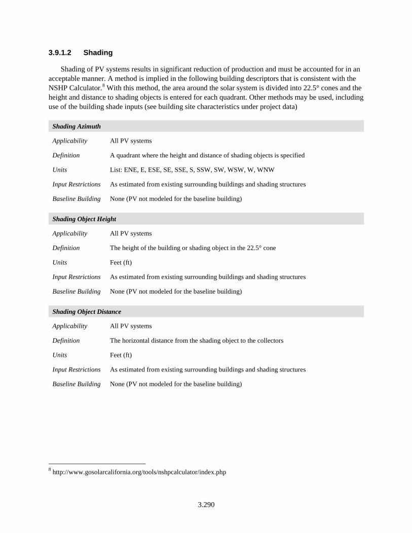
3.290
3.9.1.2 Shading
Shading of PV systems results in significant reduction of production and must be accounted for in an acceptable manner. A method is implied in the following building descriptors that is consistent with the NSHP Calculator.8 With this method, the area around the solar system is divided into 22.5° cones and the height and distance to shading objects is entered for each quadrant. Other methods may be used, including use of the building shade inputs (see building site characteristics under project data)
Shading Azimuth
Applicability All PV systems
Definition A quadrant where the height and distance of shading objects is specified
Units List: ENE, E, ESE, SE, SSE, S, SSW, SW, WSW, W, WNW
Input Restrictions As estimated from existing surrounding buildings and shading structures
Baseline Building None (PV not modeled for the baseline building)
Shading Object Height
Applicability All PV systems
Definition The height of the building or shading object in the 22.5° cone
Units Feet (ft)
Input Restrictions As estimated from existing surrounding buildings and shading structures
Baseline Building None (PV not modeled for the baseline building)
Shading Object Distance
Applicability All PV systems
Definition The horizontal distance from the shading object to the collectors
Units Feet (ft)
Input Restrictions As estimated from existing surrounding buildings and shading structures
Baseline Building None (PV not modeled for the baseline building)
8 http://www.gosolarcalifornia.org/tools/nshpcalculator/index.php
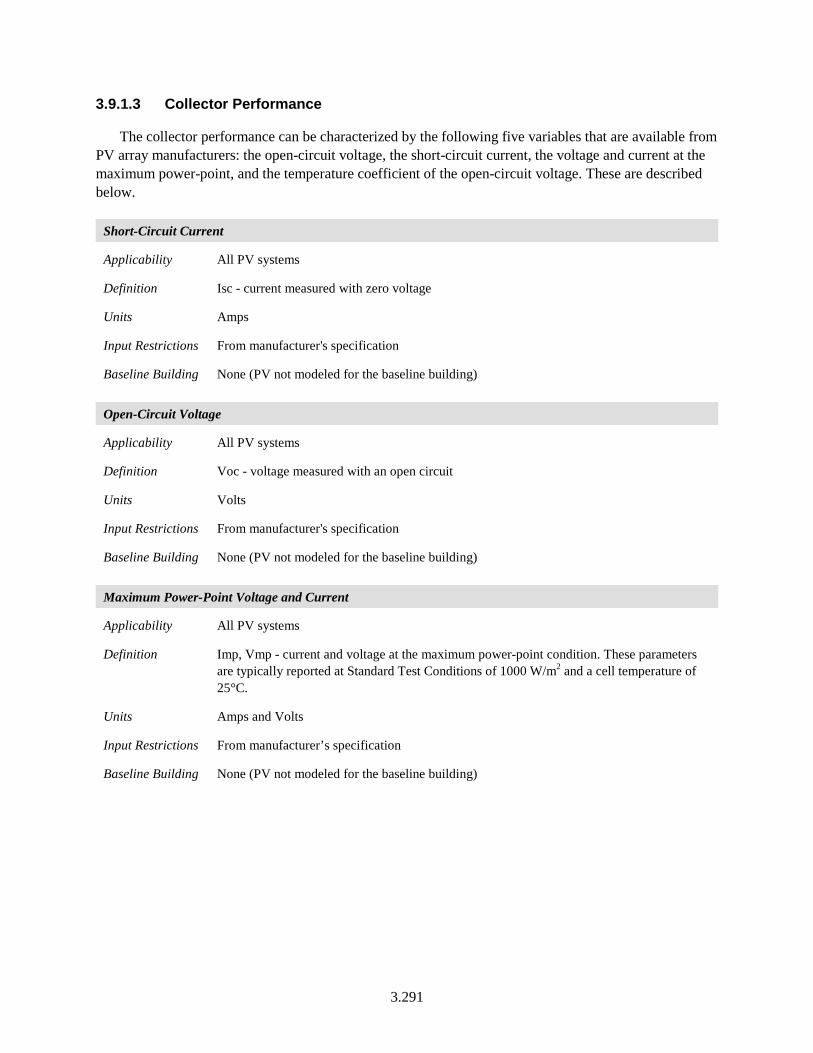
3.291
3.9.1.3 Collector Performance
The collector performance can be characterized by the following five variables that are available from PV array manufacturers: the open-circuit voltage, the short-circuit current, the voltage and current at the maximum power-point, and the temperature coefficient of the open-circuit voltage. These are described below.
Short-Circuit Current
Applicability All PV systems
Definition Isc - current measured with zero voltage
Units Amps
Input Restrictions From manufacturer's specification
Baseline Building None (PV not modeled for the baseline building)
Open-Circuit Voltage
Applicability All PV systems
Definition Voc - voltage measured with an open circuit
Units Volts
Input Restrictions From manufacturer's specification
Baseline Building None (PV not modeled for the baseline building)
Maximum Power-Point Voltage and Current
Applicability All PV systems
Definition Imp, Vmp - current and voltage at the maximum power-point condition. These parameters are typically reported at Standard Test Conditions of 1000 W/m2 and a cell temperature of 25°C.
Units Amps and Volts
Input Restrictions From manufacturer’s specification
Baseline Building None (PV not modeled for the baseline building)
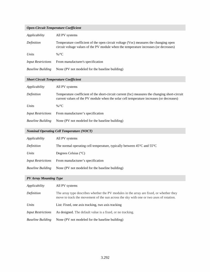
3.292
Open-Circuit Temperature Coefficient
Applicability All PV systems
Definition Temperature coefficient of the open circuit voltage (Voc) measures the changing open circuit voltage values of the PV module when the temperature increases (or decreases)
Units %/ºC
Input Restrictions From manufacturer's specification
Baseline Building None (PV not modeled for the baseline building)
Short Circuit Temperature Coefficient
Applicability All PV systems
Definition Temperature coefficient of the short-circuit current (Isc) measures the changing short-circuit current values of the PV module when the solar cell temperature increases (or decreases)
Units %/ºC
Input Restrictions From manufacturer’s specification
Baseline Building None (PV not modeled for the baseline building)
Nominal Operating Cell Temperature (NOCT)
Applicability All PV systems
Definition The normal operating cell temperature, typically between 45°C and 55°C
Units Degrees Celsius (°C)
Input Restrictions From manufacturer’s specification
Baseline Building None (PV not modeled for the baseline building)
PV Array Mounting Type
Applicability All PV systems
Definition The array type describes whether the PV modules in the array are fixed, or whether they move to track the movement of the sun across the sky with one or two axes of rotation.
Units List: Fixed, one axis tracking, two axis tracking
Input Restrictions As designed. The default value is a fixed, or no tracking.
Baseline Building None (PV not modeled for the baseline building)
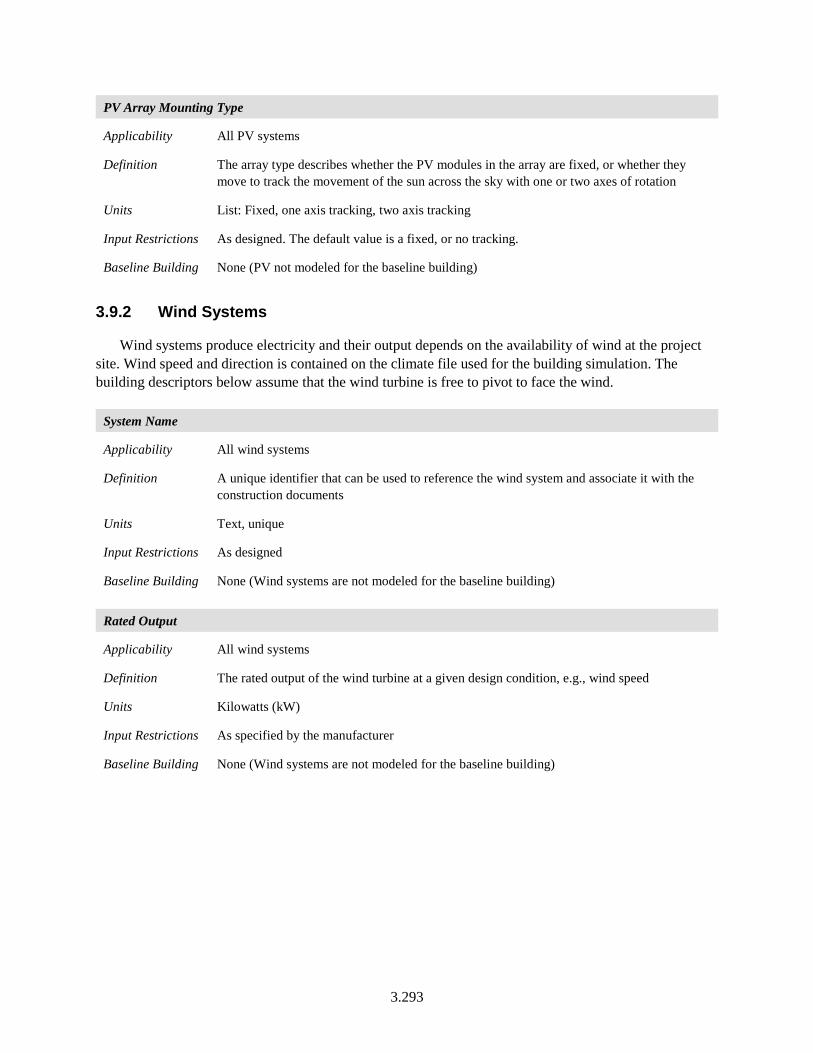
3.293
PV Array Mounting Type
Applicability All PV systems
Definition The array type describes whether the PV modules in the array are fixed, or whether they move to track the movement of the sun across the sky with one or two axes of rotation
Units List: Fixed, one axis tracking, two axis tracking
Input Restrictions As designed. The default value is a fixed, or no tracking.
Baseline Building None (PV not modeled for the baseline building)
3.9.2 Wind Systems
Wind systems produce electricity and their output depends on the availability of wind at the project site. Wind speed and direction is contained on the climate file used for the building simulation. The building descriptors below assume that the wind turbine is free to pivot to face the wind.
System Name
Applicability All wind systems
Definition A unique identifier that can be used to reference the wind system and associate it with the construction documents
Units Text, unique
Input Restrictions As designed
Baseline Building None (Wind systems are not modeled for the baseline building)
Rated Output
Applicability All wind systems
Definition The rated output of the wind turbine at a given design condition, e.g., wind speed
Units Kilowatts (kW)
Input Restrictions As specified by the manufacturer
Baseline Building None (Wind systems are not modeled for the baseline building)
3.294
Rated Wind Speed
Applicability All wind systems
Definition The wind speed at which the rated output is measured
Units Miles per hour (mph)
Input Restrictions As specified by the manufacturer
Baseline Building None (Wind systems are not modeled for the baseline building)
Cut-in Wind Speed
Applicability All wind systems
Definition The wind speed above which the system will produce useful power
Units Miles per hour (mph)
Input Restrictions As specified by the manufacturer
Baseline Building None (Wind systems are not modeled for the baseline building)
Part Load Performance
Applicability All wind systems
Definition The rated capacity gives the power production at one wind speed. The part load performance will generally be a curve that gives the output for wind speeds that are greater or lower than the rated wind speed.
Units Data structure
Input Restrictions As specified by the manufacturer
Baseline Building None (Wind systems are not modeled for the baseline building)
3.10 Common Data Structures
This section describes common data structures referenced in this chapter. The data structures presented here define objects and example parameters needed to define them. The parameters described are the most common for energy simulation engines. Other parameters or data constructs are acceptable; however, the fields used by the simulation program must be mapped to the fields used by the building descriptor.
3.10.1 Schedule
This data structure provides information on how equipment, people, lights, or other items are operated hourly. The ultimate construct of a schedule is an hourly time series for the simulation period, typically 8,760 hours (365 days, 24 hours per day). However, software has often built up the hourly schedule from 24-hour schedules for different day types: weekdays, Saturdays, Sundays, holidays, etc.
3.295
There are several types of schedules:
a. Temperature schedules specify a temperature to be maintained in a space, a temperature to be delivered from an air handler, or the leaving temperature from a chiller or other equipment.
b. Fraction schedules specify the fraction of lights that are on, the fraction of people that are in the space, the fraction of maximum infiltration, or other factors.
c. On/off schedules specify when equipment is operating or when infiltration is occurring.
d. Time period schedules define periods of time for equipment sequencing, utility tariffs, etc. A time period schedule typically breaks the year in to two or more seasons. For each season, day types are identified such as weekday, Saturday, Sunday, and holidays. Each day type in each season is then divided into time periods.
3.10.2 Holidays
A series of dates defining holidays for the simulation period. Dates identified are operated for the schedule specified for holidays.
3.10.3 Surface Geometry
This data structure represents the location, size, and position of a surface. Surfaces include roofs, walls, floors, and partitions. Surfaces are typically planar and can be represented in various manners, including the following:
• Rectangular surfaces may be represented by a height and width along with the X, Y, and Z of surface origin and the tilt and azimuth
• Surfaces may also be represented by a series of vertices (X, Y, and Z coordinates defining the perimeter of a surface). More complex polygons may be represented in this manner.
3.10.4 Opening Geometry
This data structure represents the location and size of an opening within a surface. The most common method of specifying the geometry of an opening is to identify the parent surface, the height and width of the opening, and the horizontal and vertical offset (X and Y coordinates relative to the origin of the parent surface). An opening can also include a recess into the parent surface, which provides shading. However, other geometric constructs are acceptable.
3.10.5 Opening Shade
This data structure describes the dimensions and position of external shading devices such as overhangs, side fins, or louvers that shade the opening. Overhangs are specified in terms of the projection distance, height above the opening, and extension distance on each side of the opening.
3.296
3.10.6 Construction Assembly
This data structure describes the layers that make up the construction of a wall, roof, floor, or partition. Typically, a construction consists of a sequence of materials, described from the outside surface to the inside surface.
3.10.7 Fenestration Construction
This data structure describes the frame, glass, and other features of a window or skylight. Information may be defined in multiple ways, but the criteria themselves are published as a combination of U-factor, solar heat gain coefficient (SHGC), and visible light transmission (VT). Some simulation programs use more detailed methods of describing the performance of fenestration that take into account the angle of incidence of sun striking the fenestration and other factors, such as the properties of each pane and the fill. The software only uses whole window performance properties (U-factor, SHGC, VT).
3.10.8 Material
This data structure describes a material that is used to build up a construction assembly. Typical material properties include specific heat, density, conductivity, and thickness. Materials can also be described in terms of their thermal resistance. The latter approach is sometimes used to approximate construction layers that are not homogeneous, such as framing members in combination with cavity insulation.
3.10.9 Slab Construction
This data structure describes the composition of a slab-on-grade. The model has building descriptors for the perimeter length and the F-factor, which represents the heat loss per lineal foot.
3.10.10 Exterior Surface Properties
This data structure describes the characteristics of exterior surfaces. Exterior surface properties may include emissivity, reflectivity, and roughness. The first two govern radiation exchange from the surface, while the latter governs the magnitude of the exterior air film resistance.
3.10.11 Occupant Heat Rate
This data structure represents the rate of heat and moisture generated by building occupants. This is typically specified in terms of a sensible heat rate and a latent heat rate. Both are specified in Btu/h.
3.10.12 Furniture and Contents
This data structure represents the thermal mass effect of furniture and other building contents. This is expressed in terms of lb/ft² for the space in question.
3.297
3.10.13 Reference Position in a Space
This data structure locates a reference point in a space, typically for the purposes of daylighting control. The typical construct for the reference point is a set of coordinates (X, Y, and Z) relative to the space coordinate system.
3.10.14 Two Dimensional Curve
This data structure explains one parameter in terms of another. An example is a curve that modifies the efficiency of an air conditioner relative to the fraction of time that the equipment operates within the period of an hour, for example. The relationship can be expressed in terms of the X and Y coordinates of points on the curve or it can be expressed as an equation.
3.10.15 Three Dimensional Curve
This data structure explains one parameter in terms of two others. An example is a curve that modifies the efficiency of an air conditioner relative to the outside air dry-bulb temperature and the wet-bulb temperature of air returning to the coil. The relationship is a three-dimensional surface and can be expressed in terms of the X and Y coordinates of points on the curve or it can be expressed as an equation.
3.10.16 Temperature Reset Schedule
This data structure describes the relationship between one temperature and another. For example, the independent variable might be outside air temperature and the dependent variable might be SAT. In this case, a common schedule would be to set the SAT at 55°F when the outside air temperature is 80°F or warmer and at 62°F when the outside air temperature is 58°F or cooler with the SAT scaling between 55°F and 62°F when the outside air temperature is between 80°F and 58°F.
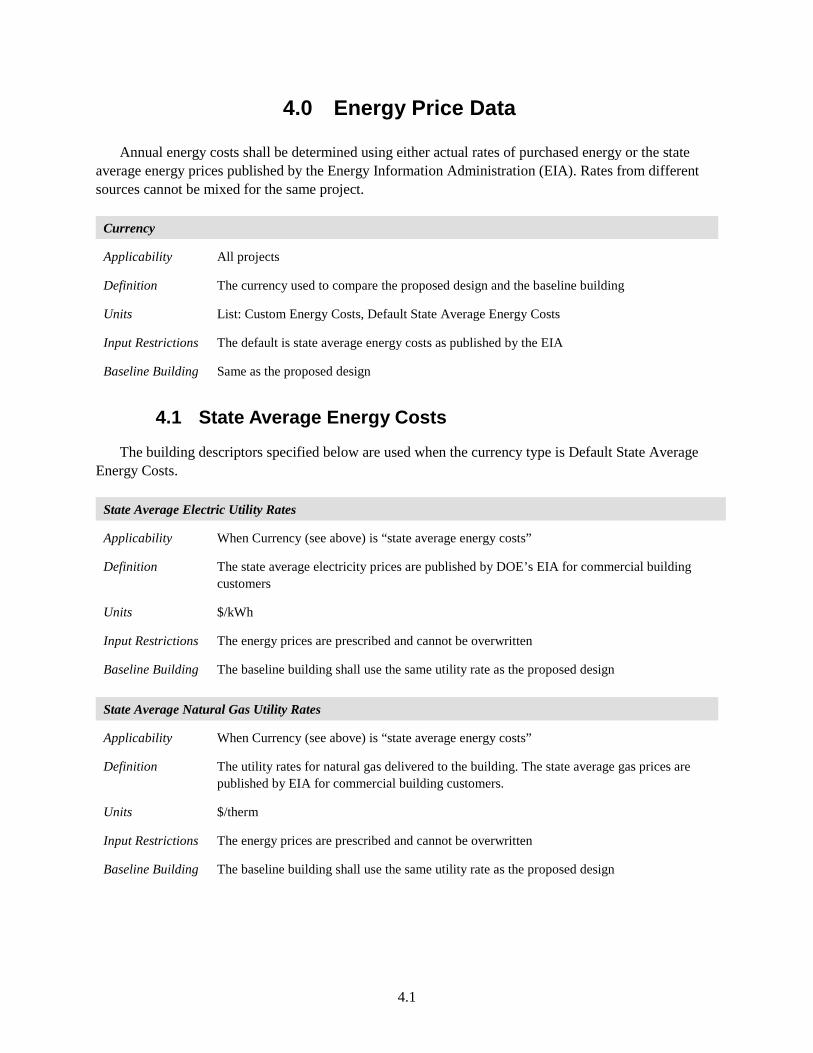
4.1
4.0 Energy Price Data
Annual energy costs shall be determined using either actual rates of purchased energy or the state average energy prices published by the Energy Information Administration (EIA). Rates from different sources cannot be mixed for the same project.
Currency
Applicability All projects
Definition The currency used to compare the proposed design and the baseline building
Units List: Custom Energy Costs, Default State Average Energy Costs
Input Restrictions The default is state average energy costs as published by the EIA
Baseline Building Same as the proposed design
4.1 State Average Energy Costs
The building descriptors specified below are used when the currency type is Default State Average Energy Costs.
State Average Electric Utility Rates
Applicability When Currency (see above) is “state average energy costs”
Definition The state average electricity prices are published by DOE’s EIA for commercial building customers
Units $/kWh
Input Restrictions The energy prices are prescribed and cannot be overwritten
Baseline Building The baseline building shall use the same utility rate as the proposed design
State Average Natural Gas Utility Rates
Applicability When Currency (see above) is “state average energy costs”
Definition The utility rates for natural gas delivered to the building. The state average gas prices are published by EIA for commercial building customers.
Units $/therm
Input Restrictions The energy prices are prescribed and cannot be overwritten
Baseline Building The baseline building shall use the same utility rate as the proposed design
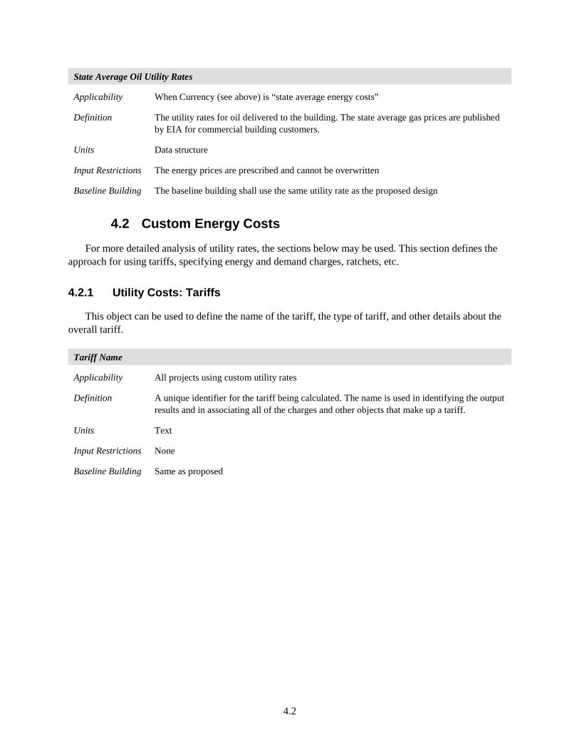
4.2
State Average Oil Utility Rates
Applicability When Currency (see above) is “state average energy costs”
Definition The utility rates for oil delivered to the building. The state average gas prices are published by EIA for commercial building customers.
Units Data structure
Input Restrictions The energy prices are prescribed and cannot be overwritten
Baseline Building The baseline building shall use the same utility rate as the proposed design
4.2 Custom Energy Costs
For more detailed analysis of utility rates, the sections below may be used. This section defines the approach for using tariffs, specifying energy and demand charges, ratchets, etc.
4.2.1 Utility Costs: Tariffs
This object can be used to define the name of the tariff, the type of tariff, and other details about the overall tariff.
Tariff Name
Applicability All projects using custom utility rates
Definition A unique identifier for the tariff being calculated. The name is used in identifying the output results and in associating all of the charges and other objects that make up a tariff.
Units Text
Input Restrictions None
Baseline Building Same as proposed
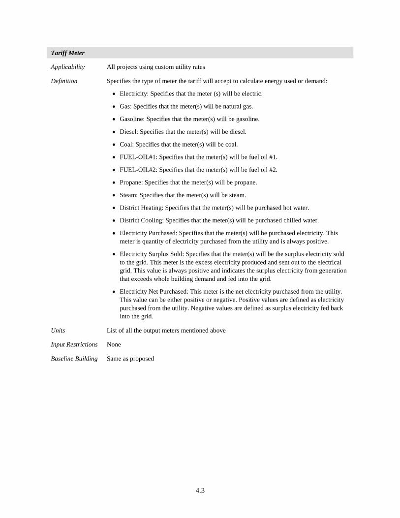
4.3
Tariff Meter
Applicability All projects using custom utility rates
Definition Specifies the type of meter the tariff will accept to calculate energy used or demand:
• Electricity: Specifies that the meter (s) will be electric.
• Gas: Specifies that the meter(s) will be natural gas.
• Gasoline: Specifies that the meter(s) will be gasoline.
• Diesel: Specifies that the meter(s) will be diesel.
• Coal: Specifies that the meter(s) will be coal.
• FUEL-OIL#1: Specifies that the meter(s) will be fuel oil #1.
• FUEL-OIL#2: Specifies that the meter(s) will be fuel oil #2.
• Propane: Specifies that the meter(s) will be propane.
• Steam: Specifies that the meter(s) will be steam.
• District Heating: Specifies that the meter(s) will be purchased hot water.
• District Cooling: Specifies that the meter(s) will be purchased chilled water.
• Electricity Purchased: Specifies that the meter(s) will be purchased electricity. This meter is quantity of electricity purchased from the utility and is always positive.
• Electricity Surplus Sold: Specifies that the meter(s) will be the surplus electricity sold to the grid. This meter is the excess electricity produced and sent out to the electrical grid. This value is always positive and indicates the surplus electricity from generation that exceeds whole building demand and fed into the grid.
• Electricity Net Purchased: This meter is the net electricity purchased from the utility. This value can be either positive or negative. Positive values are defined as electricity purchased from the utility. Negative values are defined as surplus electricity fed back into the grid.
Units List of all the output meters mentioned above
Input Restrictions None
Baseline Building Same as proposed
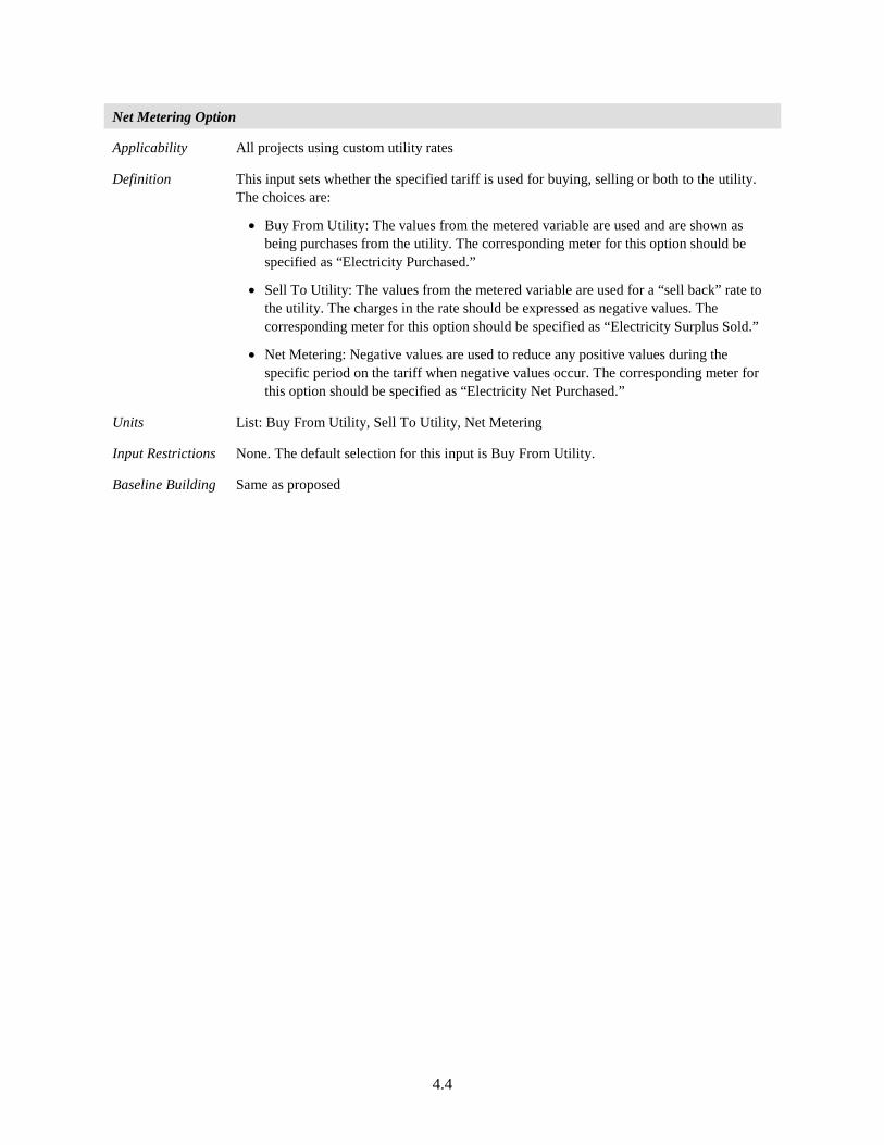
4.4
Net Metering Option
Applicability All projects using custom utility rates
Definition This input sets whether the specified tariff is used for buying, selling or both to the utility. The choices are:
• Buy From Utility: The values from the metered variable are used and are shown as being purchases from the utility. The corresponding meter for this option should be specified as “Electricity Purchased.”
• Sell To Utility: The values from the metered variable are used for a “sell back” rate to the utility. The charges in the rate should be expressed as negative values. The corresponding meter for this option should be specified as “Electricity Surplus Sold.”
• Net Metering: Negative values are used to reduce any positive values during the specific period on the tariff when negative values occur. The corresponding meter for this option should be specified as “Electricity Net Purchased.”
Units List: Buy From Utility, Sell To Utility, Net Metering
Input Restrictions None. The default selection for this input is Buy From Utility.
Baseline Building Same as proposed
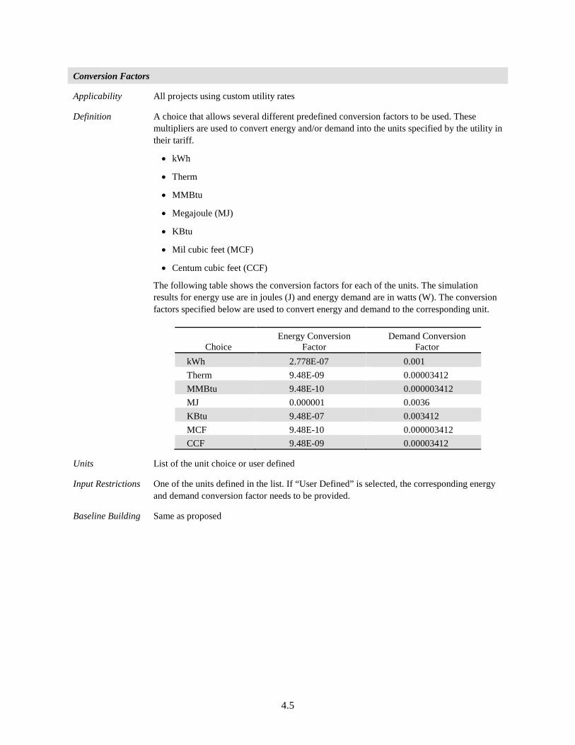
4.5
Conversion Factors
Applicability All projects using custom utility rates
Definition A choice that allows several different predefined conversion factors to be used. These multipliers are used to convert energy and/or demand into the units specified by the utility in their tariff.
• kWh
• Therm
• MMBtu
• Megajoule (MJ)
• KBtu
• Mil cubic feet (MCF)
• Centum cubic feet (CCF)
The following table shows the conversion factors for each of the units. The simulation results for energy use are in joules (J) and energy demand are in watts (W). The conversion factors specified below are used to convert energy and demand to the corresponding unit.
Choice Energy Conversion
Factor Demand Conversion
Factor kWh 2.778E-07 0.001 Therm 9.48E-09 0.00003412 MMBtu 9.48E-10 0.000003412 MJ 0.000001 0.0036 KBtu 9.48E-07 0.003412 MCF 9.48E-10 0.000003412 CCF 9.48E-09 0.00003412
Units List of the unit choice or user defined
Input Restrictions One of the units defined in the list. If “User Defined” is selected, the corresponding energy and demand conversion factor needs to be provided.
Baseline Building Same as proposed
4.6
4.2.2 Utility Costs: Charges
Utility charges can be energy charges or demand charges. Energy or demand charges can be either a fixed flat rate based on consumption, or vary based on time of use (TOU) or season of use. Some utilities also follow real-time pricing where tariffs can change frequently. Also with charges based on consumption, a utility may also charge a fixed monthly fee irrespective of energy use or energy demand. The descriptors in the section below describe each of these charges.
Tariff Variability
Applicability All projects using custom utility rates
Definition Tariffs can be defined as a flat rate, or vary by the TOU, season or a real-time pricing. The variance in tariff can be defined through one or more of the variables below.
• Monthly
This would be a flat monthly rate charged by the utility per customer. This is irrespective of energy use or energy demand.
• Time of Use Period Schedule
This schedule defines the time-of-use periods that occur each day. The different variables that can occur in a day are
Peak
Shoulder
Off-peak
Mid-peak
Both energy and demand charges can be defined for each TOU period.
• Seasonal Schedules
• Utilities can also vary tariffs based on season. Tariffs can be defined for the following seasons
Winter
Spring
Summer
Autumn
Units List: Monthly Charge, TOU Period Schedule, Seasonal Schedule
Input Restrictions None
Baseline Building Same as proposed
4.7
Time of Use Period Schedule
Applicability All projects using custom utility rates
Definition Unique name of a yearly schedule that specifies the TOU type for the entire year. The schedule specifies months and times in a year billed as peak, shoulder, off-peak, or mid-peak. This schedule is used for all TOU energy billing. TOU demand charges are calculated using the block-charges input.
Units Schedule name with TOU variables defined
Input Restrictions None
Baseline Building Same as proposed
Seasonal Schedule
Applicability All projects using custom utility rates
Definition Unique name of a yearly schedule that specifies the season type for the entire year. The schedule specifies months in a year billed using winter, summer, autumn, or spring tariffs. This schedule is used for the billing of all seasonal energy and demand charges using the block charges input.
Units Schedule name with seasonal variables defined
Input Restrictions None
Baseline Building Same as proposed
4.8
Demand Window
Applicability All projects using custom utility rates
Definition The determination of demand can vary by utility. Some utilities use the peak instantaneous demand measured, but most use a 15-minute average demand or a 1-hour average demand. Some gas utilities measure demand as the use during the peak day or peak week.
The choices for demand window are:
• Quarter hour
• Half hour
• Full hour
• Day
• Week
The value for demand window must coincide with the value for number of timesteps. This is explained in Section 3.1.8 of this manual.
Units List: Quarter Hour, Half Hour, Full Hour, Day, Week
Input Restrictions None. If no value is entered, Quarter Hour is assumed.
Baseline Building Same as proposed
Monthly Charge
Applicability All projects using custom utility rates
Definition Many utilities refer to this as a customer charge. This input accepts a list of 12 numeric values that add a fixed monthly charge to each billing cycle. If a single value is entered, the value will be used for all 12 billing periods.
Units $/month
Input Restrictions None
Baseline Building Same as proposed
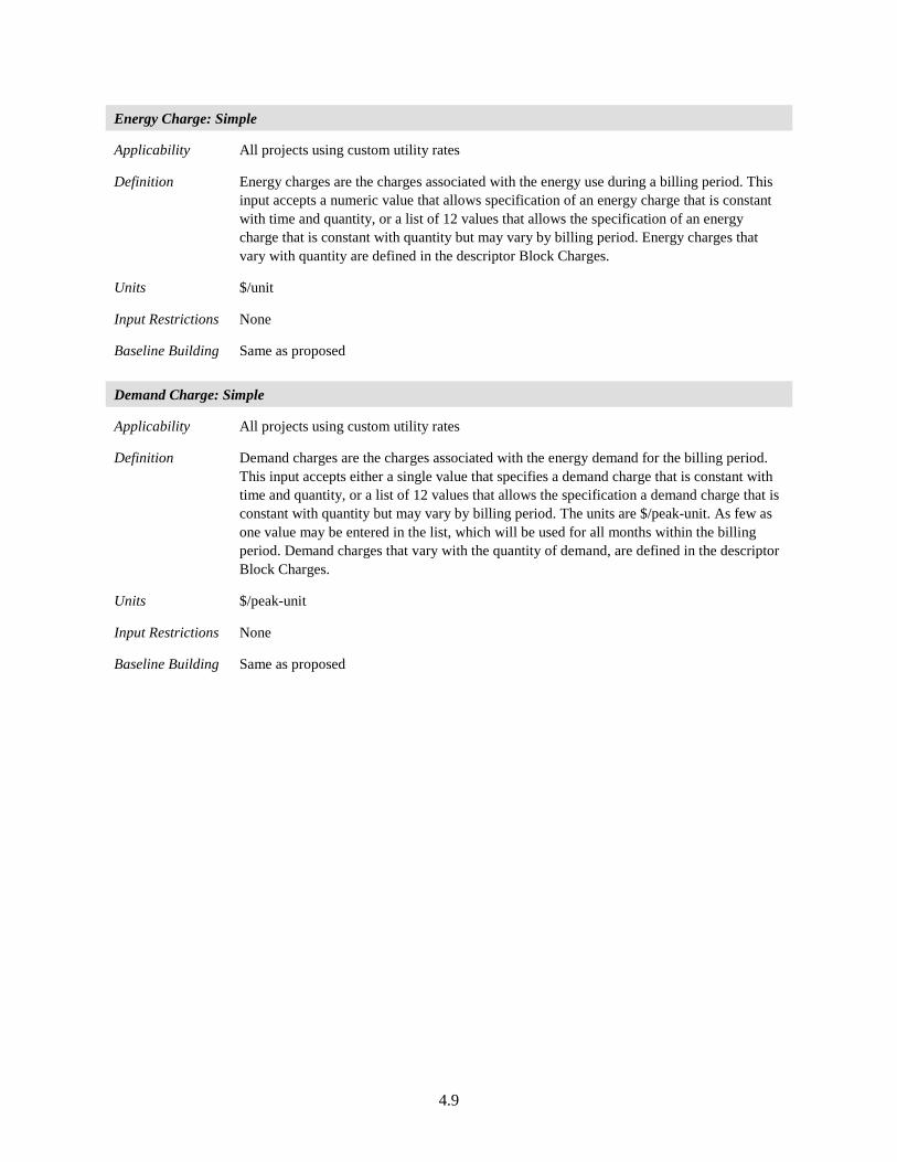
4.9
Energy Charge: Simple
Applicability All projects using custom utility rates
Definition Energy charges are the charges associated with the energy use during a billing period. This input accepts a numeric value that allows specification of an energy charge that is constant with time and quantity, or a list of 12 values that allows the specification of an energy charge that is constant with quantity but may vary by billing period. Energy charges that vary with quantity are defined in the descriptor Block Charges.
Units $/unit
Input Restrictions None
Baseline Building Same as proposed
Demand Charge: Simple
Applicability All projects using custom utility rates
Definition Demand charges are the charges associated with the energy demand for the billing period. This input accepts either a single value that specifies a demand charge that is constant with time and quantity, or a list of 12 values that allows the specification a demand charge that is constant with quantity but may vary by billing period. The units are $/peak-unit. As few as one value may be entered in the list, which will be used for all months within the billing period. Demand charges that vary with the quantity of demand, are defined in the descriptor Block Charges.
Units $/peak-unit
Input Restrictions None
Baseline Building Same as proposed
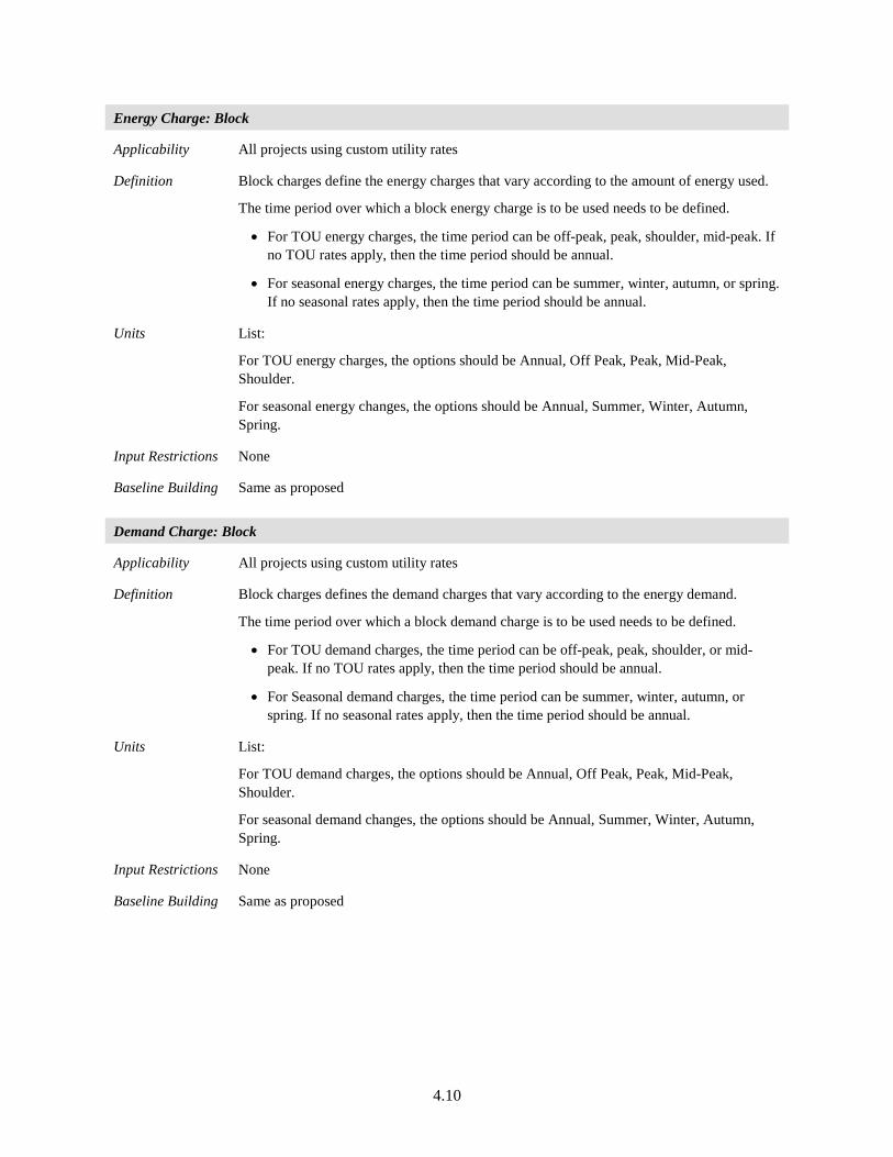
4.10
Energy Charge: Block
Applicability All projects using custom utility rates
Definition Block charges define the energy charges that vary according to the amount of energy used.
The time period over which a block energy charge is to be used needs to be defined.
• For TOU energy charges, the time period can be off-peak, peak, shoulder, mid-peak. If no TOU rates apply, then the time period should be annual.
• For seasonal energy charges, the time period can be summer, winter, autumn, or spring. If no seasonal rates apply, then the time period should be annual.
Units List:
For TOU energy charges, the options should be Annual, Off Peak, Peak, Mid-Peak, Shoulder.
For seasonal energy changes, the options should be Annual, Summer, Winter, Autumn, Spring.
Input Restrictions None
Baseline Building Same as proposed
Demand Charge: Block
Applicability All projects using custom utility rates
Definition Block charges defines the demand charges that vary according to the energy demand.
The time period over which a block demand charge is to be used needs to be defined.
• For TOU demand charges, the time period can be off-peak, peak, shoulder, or mid-peak. If no TOU rates apply, then the time period should be annual.
• For Seasonal demand charges, the time period can be summer, winter, autumn, or spring. If no seasonal rates apply, then the time period should be annual.
Units List:
For TOU demand charges, the options should be Annual, Off Peak, Peak, Mid-Peak, Shoulder.
For seasonal demand changes, the options should be Annual, Summer, Winter, Autumn, Spring.
Input Restrictions None
Baseline Building Same as proposed
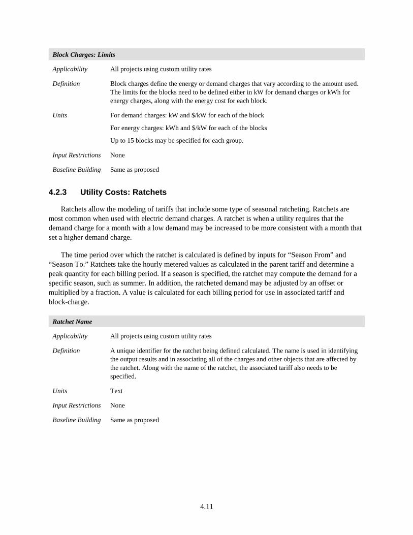
4.11
Block Charges: Limits
Applicability All projects using custom utility rates
Definition Block charges define the energy or demand charges that vary according to the amount used. The limits for the blocks need to be defined either in kW for demand charges or kWh for energy charges, along with the energy cost for each block.
Units For demand charges: kW and $/kW for each of the block
For energy charges: kWh and $/kW for each of the blocks
Up to 15 blocks may be specified for each group.
Input Restrictions None
Baseline Building Same as proposed
4.2.3 Utility Costs: Ratchets
Ratchets allow the modeling of tariffs that include some type of seasonal ratcheting. Ratchets are most common when used with electric demand charges. A ratchet is when a utility requires that the demand charge for a month with a low demand may be increased to be more consistent with a month that set a higher demand charge.
The time period over which the ratchet is calculated is defined by inputs for “Season From” and “Season To.” Ratchets take the hourly metered values as calculated in the parent tariff and determine a peak quantity for each billing period. If a season is specified, the ratchet may compute the demand for a specific season, such as summer. In addition, the ratcheted demand may be adjusted by an offset or multiplied by a fraction. A value is calculated for each billing period for use in associated tariff and block-charge.
Ratchet Name
Applicability All projects using custom utility rates
Definition A unique identifier for the ratchet being defined calculated. The name is used in identifying the output results and in associating all of the charges and other objects that are affected by the ratchet. Along with the name of the ratchet, the associated tariff also needs to be specified.
Units Text
Input Restrictions None
Baseline Building Same as proposed
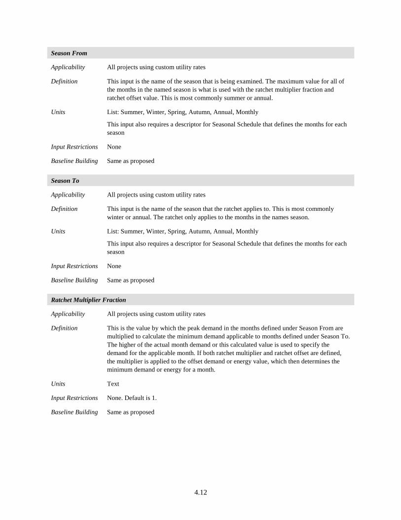
4.12
Season From
Applicability All projects using custom utility rates
Definition This input is the name of the season that is being examined. The maximum value for all of the months in the named season is what is used with the ratchet multiplier fraction and ratchet offset value. This is most commonly summer or annual.
Units List: Summer, Winter, Spring, Autumn, Annual, Monthly
This input also requires a descriptor for Seasonal Schedule that defines the months for each season
Input Restrictions None
Baseline Building Same as proposed
Season To
Applicability All projects using custom utility rates
Definition This input is the name of the season that the ratchet applies to. This is most commonly winter or annual. The ratchet only applies to the months in the names season.
Units List: Summer, Winter, Spring, Autumn, Annual, Monthly
This input also requires a descriptor for Seasonal Schedule that defines the months for each season
Input Restrictions None
Baseline Building Same as proposed
Ratchet Multiplier Fraction
Applicability All projects using custom utility rates
Definition This is the value by which the peak demand in the months defined under Season From are multiplied to calculate the minimum demand applicable to months defined under Season To. The higher of the actual month demand or this calculated value is used to specify the demand for the applicable month. If both ratchet multiplier and ratchet offset are defined, the multiplier is applied to the offset demand or energy value, which then determines the minimum demand or energy for a month.
Units Text
Input Restrictions None. Default is 1.
Baseline Building Same as proposed
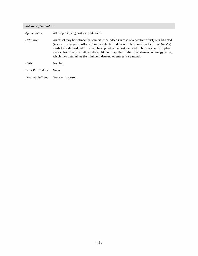
4.13
Ratchet Offset Value
Applicability All projects using custom utility rates
Definition An offset may be defined that can either be added (in case of a positive offset) or subtracted (in case of a negative offset) from the calculated demand. The demand offset value (in kW) needs to be defined, which would be applied to the peak demand. If both ratchet multiplier and ratchet offset are defined, the multiplier is applied to the offset demand or energy value, which then determines the minimum demand or energy for a month.
Units Number
Input Restrictions None
Baseline Building Same as proposed
5.1
5.0 Reporting
This chapter summarizes the requisite content and format of the PRM-RM standard reports. The establishment of these reports will standardize the way energy modeling output data is presented to various rating authorities. By standardizing the reports, all rating authorities will be able to view the same building information and evaluate the project for certification, labeling, or tax credit.
Simulated performance shall be documented, and documentation shall be submitted to the rating authority. The information shall be submitted in a report and shall include the following.
5.1 Content
The reporting requirements are organized into five reports. The first four reports summarize the reporting requirements for Standard 90.1-2016. These can be automatically generated from an energy modeling tool which automates the baseline model generation. The fifth report includes additional documentation that needs to be provided by the user and isn’t generated by the software tool.
Standard Reports Generated by Software Tool: a. Building Summary
The Building Summary contains basic building information such as project title, location, and size. This brief report provides essential building data at a glance.
b. Performance Outputs The Performance Outputs report summarizes energy use by fuel types and end uses. It also reports simulation advisory messages including errors, warnings, and UMLH.
c. Model Inputs The Model Inputs report is required to have documentation of all energy features that are different between the proposed and baseline model, and includes a checklist to verify that the mandatory code requirements and documentation of inputs that use the exceptional calculation method or are flagged as being different between the baseline and proposed.
d. Representations The Representations report includes all relevant building titles and claims.
Reports Provided by User: a. Supporting Documentation
Supporting documentation needs to include detailed architectural and mechanical drawings to support the inputs entered into the energy modeling software as well as calculations supporting the exceptional calculation methods used and inputs flagged by the tool as different between the baseline and proposed.
5.2
5.1.1 Building Summary
This section will include a brief description of the project, the simulation program used, the version of the simulation program, the project location, and information on building owner, architect, engineer, etc. The reporting requirements for this section are listed below:
1. Building Information a. Project name b. Project address (including city and state) c. Analysis date and time d. Climate zone e. Project type (new construction, alterations, additions) f. Number of floors (above grade and below grade) g. Floor Area
i. Conditioned floor area ii. Unconditioned floor area
iii. Total area h. Window-to-wall ratio i. Building use types
i. Area of each use type ii. Space conditioning category for each use type
j. Applicable energy code building is permitted under k. Weather file used l. Simulation program used m. Version of simulation program n. Units of measure
2. Stakeholder Information This information needs to be provided for the building owner, engineer, architect, and energy modeler.
a. Role b. Last name c. First name d. Address (including city and state) e. Contact information (phone number or email address)
5.1.2 Performance Outputs
The performance output section will summarize the proposed building performance and the PCI calculations. It should summarize the calculation of the Building Performance Factor (BPF) for buildings which have multiple use types, the PCIt value which accounts for regulated and unregulated loads and the PCI calculations for the proposed design. Where a building has multiple area types, the required BPF shall be equal to the area-weighted average of the building area types, refer to Section 1.3 for details. For buildings where PCI < PCIt the software tool should identify that the building complies with Standard
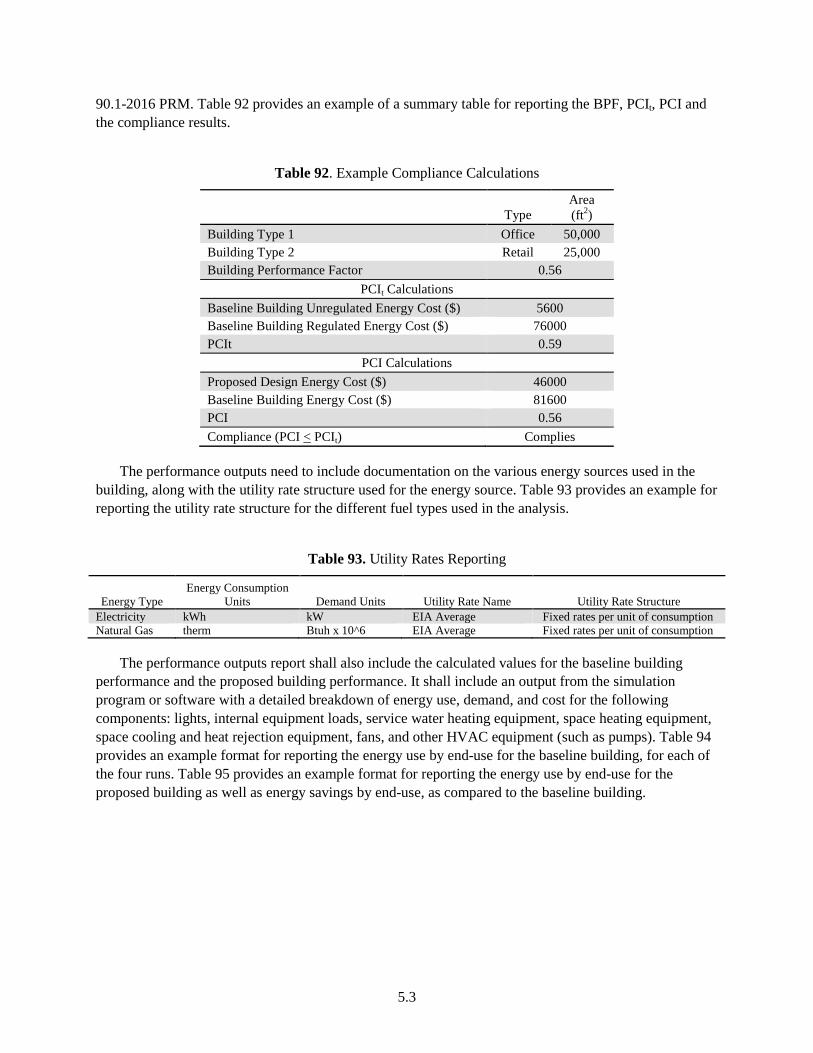
5.3
90.1-2016 PRM. Table 92 provides an example of a summary table for reporting the BPF, PCIt, PCI and the compliance results.
Table 92. Example Compliance Calculations
Type Area (ft2)
Building Type 1 Office 50,000 Building Type 2 Retail 25,000 Building Performance Factor 0.56
PCIt Calculations Baseline Building Unregulated Energy Cost ($) 5600 Baseline Building Regulated Energy Cost ($) 76000 PCIt 0.59
PCI Calculations Proposed Design Energy Cost ($) 46000 Baseline Building Energy Cost ($) 81600 PCI 0.56 Compliance (PCI < PCIt) Complies
The performance outputs need to include documentation on the various energy sources used in the building, along with the utility rate structure used for the energy source. Table 93 provides an example for reporting the utility rate structure for the different fuel types used in the analysis.
Table 93. Utility Rates Reporting
Energy Type Energy Consumption
Units Demand Units Utility Rate Name Utility Rate Structure Electricity kWh kW EIA Average Fixed rates per unit of consumption Natural Gas therm Btuh x 10^6 EIA Average Fixed rates per unit of consumption
The performance outputs report shall also include the calculated values for the baseline building performance and the proposed building performance. It shall include an output from the simulation program or software with a detailed breakdown of energy use, demand, and cost for the following components: lights, internal equipment loads, service water heating equipment, space heating equipment, space cooling and heat rejection equipment, fans, and other HVAC equipment (such as pumps). Table 94 provides an example format for reporting the energy use by end-use for the baseline building, for each of the four runs. Table 95 provides an example format for reporting the energy use by end-use for the proposed building as well as energy savings by end-use, as compared to the baseline building.
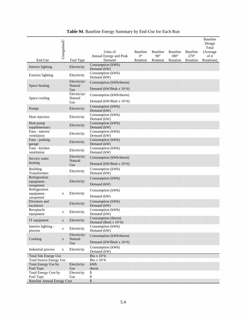
5.4
Table 94. Baseline Energy Summary by End-Use for Each Run
End Use Unr
egul
ated
? Fuel Type
Units of Annual Energy and Peak
Demand
Baseline 0°
Rotation
Baseline 90°
Rotation
Baseline 180°
Rotation
Baseline 270°
Rotation
Baseline Design Total
(Average of 4
Rotations)
Interior lighting Electricity Consumption (kWh) Demand (kW)
Exterior lighting Electricity Consumption (kWh) Demand (kW)
Space heating Electricity/ Natural Gas
Consumption (kWh/therm)
Demand (kW/Btuh x 10^6)
Space cooling Electricity/ Natural Gas
Consumption (kWh/therm)
Demand (kW/Btuh x 10^6)
Pumps Electricity Consumption (kWh) Demand (kW)
Heat rejection Electricity Consumption (kWh) Demand (kW)
Heat pump supplementary Electricity Consumption (kWh)
Demand (kW) Fans - interior ventilation Electricity Consumption (kWh)
Demand (kW) Fans - parking garage Electricity Consumption (kWh)
Demand (kW) Fans - kitchen ventilation Electricity Consumption (kWh)
Demand (kW)
Service water heating
Electricity/ Natural Gas
Consumption (kWh/therm)
Demand (kW/Btuh x 10^6) Building Transformers Electricity Consumption (kWh)
Demand (kW) Refrigeration equipment - unregulated
Electricity Consumption (kWh)
Demand (kW) Refrigeration equipment - unregulated
x Electricity Consumption (kWh)
Demand (kW) Elevators and escalators Electricity Consumption (kWh)
Demand (kW) Receptacle equipment x Electricity Consumption (kWh)
Demand (kW)
IT equipment x Electricity Consumption (therm) Demand (Btuh x 10^6)
Interior lighting - process x Electricity Consumption (kWh)
Demand (kW)
Cooking x Electricity/ Natural Gas
Consumption (kWh/therm)
Demand (kW/Btuh x 10^6)
Industrial process x Electricity Consumption (kWh) Demand (kW)
Total Site Energy Use Btu x 10^6 Total Source Energy Use Btu x 10^6 Total Energy Use by Fuel Type
Electricity kWh Gas therm
Total Energy Cost by Fuel Type
Electricity $ Gas $
Baseline Annual Energy Cost $
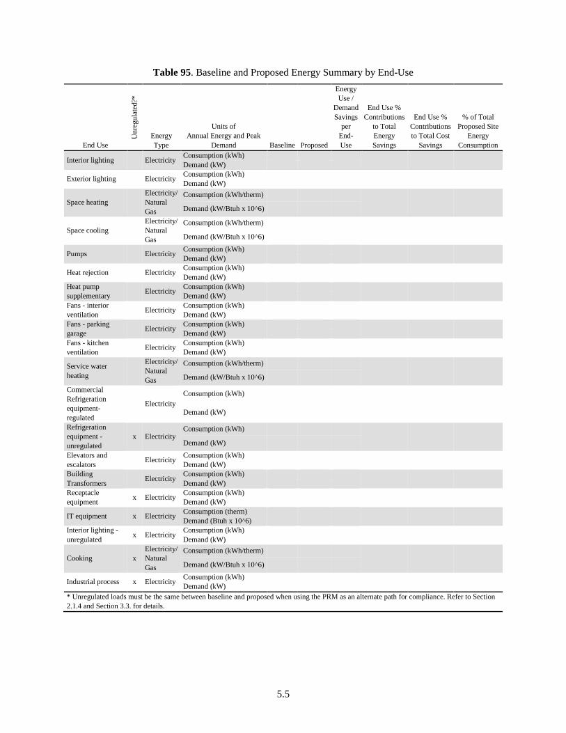
5.5
Table 95. Baseline and Proposed Energy Summary by End-Use
End Use U
nreg
ulat
ed?*
Energy Type
Units of Annual Energy and Peak
Demand Baseline Proposed
Energy Use /
Demand Savings
per End-Use
End Use % Contributions
to Total Energy Savings
End Use % Contributions to Total Cost
Savings
% of Total Proposed Site
Energy Consumption
Interior lighting Electricity Consumption (kWh) Demand (kW)
Exterior lighting Electricity Consumption (kWh) Demand (kW)
Space heating Electricity/ Natural Gas
Consumption (kWh/therm)
Demand (kW/Btuh x 10^6)
Space cooling Electricity/ Natural Gas
Consumption (kWh/therm)
Demand (kW/Btuh x 10^6)
Pumps Electricity Consumption (kWh) Demand (kW)
Heat rejection Electricity Consumption (kWh) Demand (kW) Heat pump supplementary Electricity Consumption (kWh) Demand (kW) Fans - interior ventilation Electricity Consumption (kWh) Demand (kW) Fans - parking garage Electricity Consumption (kWh) Demand (kW) Fans - kitchen ventilation Electricity Consumption (kWh) Demand (kW)
Service water heating
Electricity/ Natural Gas
Consumption (kWh/therm)
Demand (kW/Btuh x 10^6)
Commercial Refrigeration equipment- regulated
Electricity Consumption (kWh)
Demand (kW)
Refrigeration equipment - unregulated
x Electricity Consumption (kWh)
Demand (kW)
Elevators and escalators Electricity Consumption (kWh) Demand (kW) Building Transformers Electricity Consumption (kWh) Demand (kW) Receptacle equipment x Electricity Consumption (kWh) Demand (kW)
IT equipment x Electricity Consumption (therm) Demand (Btuh x 10^6) Interior lighting - unregulated x Electricity Consumption (kWh) Demand (kW)
Cooking x Electricity/ Natural Gas
Consumption (kWh/therm)
Demand (kW/Btuh x 10^6)
Industrial process x Electricity Consumption (kWh) Demand (kW)
* Unregulated loads must be the same between baseline and proposed when using the PRM as an alternate path for compliance. Refer to Section 2.1.4 and Section 3.3. for details.
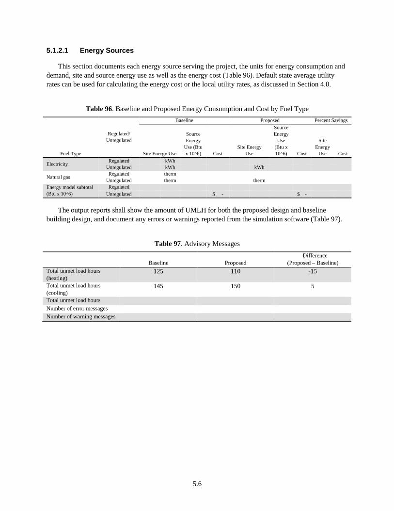
5.6
5.1.2.1 Energy Sources
This section documents each energy source serving the project, the units for energy consumption and demand, site and source energy use as well as the energy cost (Table 96). Default state average utility rates can be used for calculating the energy cost or the local utility rates, as discussed in Section 4.0.
Table 96. Baseline and Proposed Energy Consumption and Cost by Fuel Type
Fuel Type
Regulated/ Unregulated
Baseline Proposed Percent Savings
Site Energy Use
Source Energy
Use (Btu x 10^6) Cost
Site Energy Use
Source Energy
Use (Btu x 10^6) Cost
Site Energy
Use Cost
Electricity Regulated kWh Unregulated kWh kWh
Natural gas Regulated therm Unregulated therm therm
Energy model subtotal (Btu x 10^6)
Regulated Unregulated $ - $ -
The output reports shall show the amount of UMLH for both the proposed design and baseline building design, and document any errors or warnings reported from the simulation software (Table 97).
Table 97. Advisory Messages
Baseline Proposed Difference
(Proposed – Baseline) Total unmet load hours (heating)
125 110 -15
Total unmet load hours (cooling)
145 150 5
Total unmet load hours Number of error messages Number of warning messages
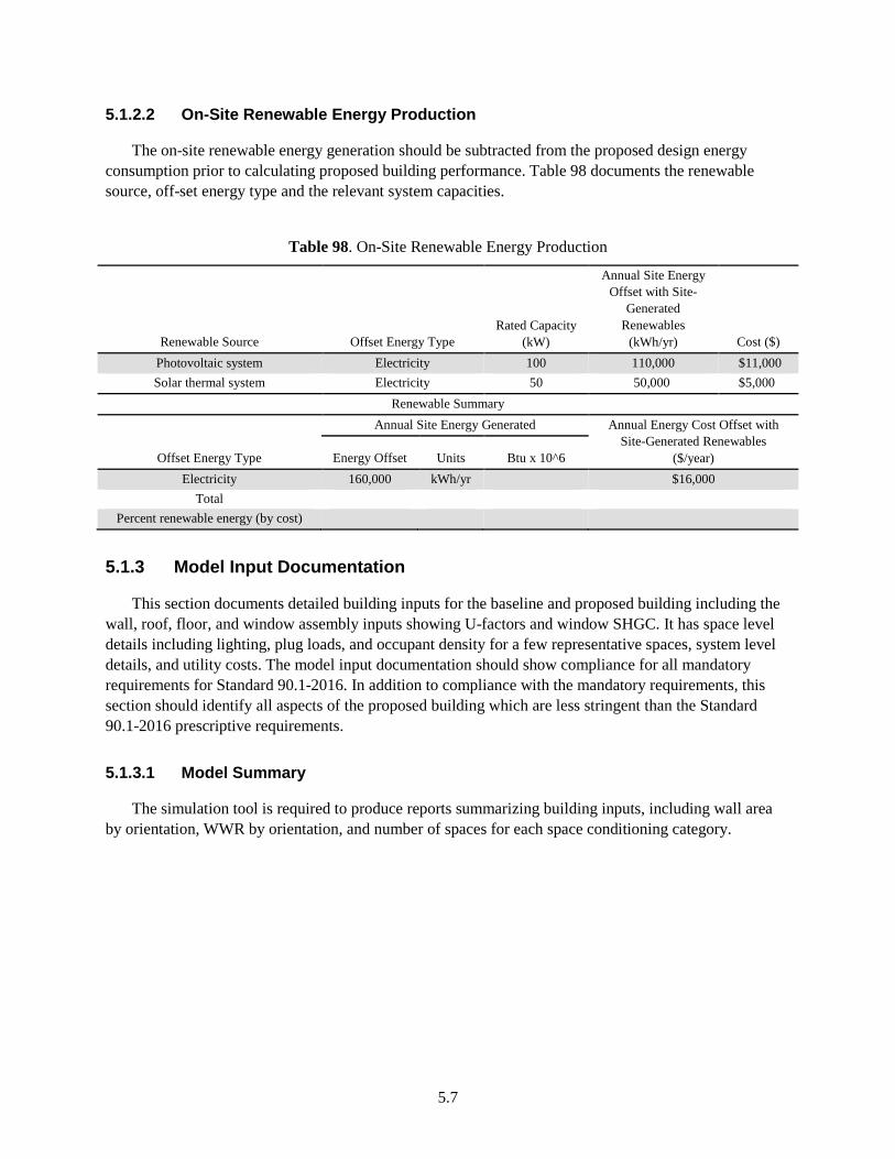
5.7
5.1.2.2 On-Site Renewable Energy Production
The on-site renewable energy generation should be subtracted from the proposed design energy consumption prior to calculating proposed building performance. Table 98 documents the renewable source, off-set energy type and the relevant system capacities.
Table 98. On-Site Renewable Energy Production
Renewable Source Offset Energy Type Rated Capacity
(kW)
Annual Site Energy Offset with Site-
Generated Renewables
(kWh/yr) Cost ($) Photovoltaic system Electricity 100 110,000 $11,000 Solar thermal system Electricity 50 50,000 $5,000
Renewable Summary
Offset Energy Type
Annual Site Energy Generated Annual Energy Cost Offset with Site-Generated Renewables
($/year) Energy Offset Units Btu x 10^6 Electricity 160,000 kWh/yr $16,000
Total Percent renewable energy (by cost)
5.1.3 Model Input Documentation
This section documents detailed building inputs for the baseline and proposed building including the wall, roof, floor, and window assembly inputs showing U-factors and window SHGC. It has space level details including lighting, plug loads, and occupant density for a few representative spaces, system level details, and utility costs. The model input documentation should show compliance for all mandatory requirements for Standard 90.1-2016. In addition to compliance with the mandatory requirements, this section should identify all aspects of the proposed building which are less stringent than the Standard 90.1-2016 prescriptive requirements.
5.1.3.1 Model Summary
The simulation tool is required to produce reports summarizing building inputs, including wall area by orientation, WWR by orientation, and number of spaces for each space conditioning category.
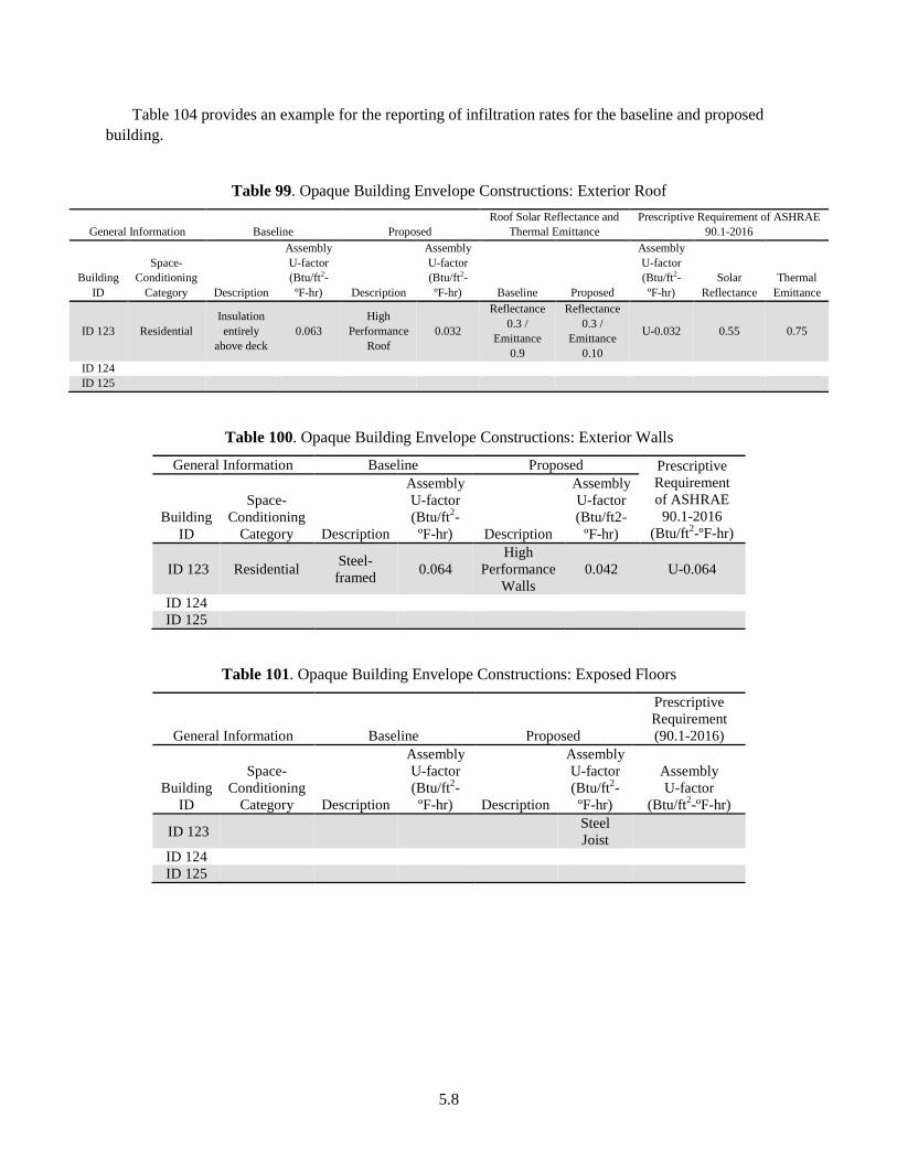
5.8
Table 104 provides an example for the reporting of infiltration rates for the baseline and proposed building.
Table 99. Opaque Building Envelope Constructions: Exterior Roof
General Information Baseline Proposed Roof Solar Reflectance and
Thermal Emittance Prescriptive Requirement of ASHRAE
90.1-2016
Building ID
Space-Conditioning
Category Description
Assembly U-factor (Btu/ft2-ºF-hr) Description
Assembly U-factor (Btu/ft2-ºF-hr) Baseline Proposed
Assembly U-factor (Btu/ft2-ºF-hr)
Solar Reflectance
Thermal Emittance
ID 123 Residential Insulation entirely
above deck 0.063
High Performance
Roof 0.032
Reflectance 0.3 /
Emittance 0.9
Reflectance 0.3 /
Emittance 0.10
U-0.032 0.55 0.75
ID 124 ID 125
Table 100. Opaque Building Envelope Constructions: Exterior Walls
General Information Baseline Proposed Prescriptive Requirement of ASHRAE 90.1-2016
(Btu/ft2-ºF-hr) Building
ID
Space-Conditioning
Category Description
Assembly U-factor (Btu/ft2-ºF-hr) Description
Assembly U-factor (Btu/ft2-
ºF-hr)
ID 123 Residential Steel-framed 0.064
High Performance
Walls 0.042 U-0.064
ID 124 ID 125
Table 101. Opaque Building Envelope Constructions: Exposed Floors
General Information Baseline Proposed
Prescriptive Requirement (90.1-2016)
Building ID
Space-Conditioning
Category Description
Assembly U-factor (Btu/ft2-ºF-hr) Description
Assembly U-factor (Btu/ft2-ºF-hr)
Assembly U-factor
(Btu/ft2-ºF-hr)
ID 123 Steel Joist
ID 124 ID 125
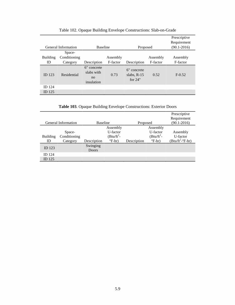
5.9
Table 102. Opaque Building Envelope Constructions: Slab-on-Grade
General Information Baseline Proposed
Prescriptive Requirement (90.1-2016)
Building ID
Space-Conditioning
Category Description Assembly F-factor Description
Assembly F-factor
Assembly F-factor
ID 123 Residential
6" concrete slabs with
no insulation
0.73 6" concrete slabs, R-15
for 24" 0.52 F-0.52
ID 124 ID 125
Table 103. Opaque Building Envelope Constructions: Exterior Doors
General Information Baseline Proposed
Prescriptive Requirement (90.1-2016)
Building ID
Space-Conditioning
Category Description
Assembly U-factor (Btu/ft2-ºF-hr) Description
Assembly U-factor (Btu/ft2-ºF-hr)
Assembly U-factor
(Btu/ft2-ºF-hr)
ID 123 Swinging Doors
ID 124 ID 125
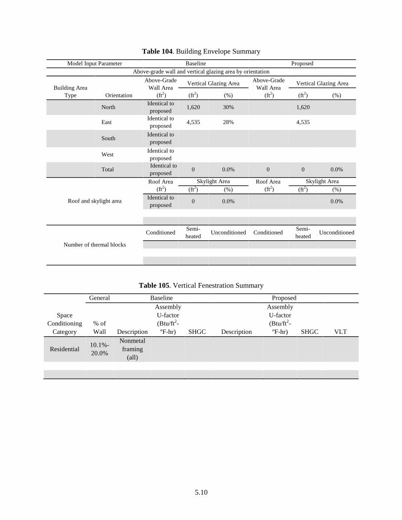
5.10
Table 104. Building Envelope Summary Model Input Parameter Baseline Proposed
Above-grade wall and vertical glazing area by orientation
Building Area Type Orientation
Above-Grade Wall Area
(ft2)
Vertical Glazing Area Above-Grade Wall Area
(ft2)
Vertical Glazing Area
(ft2) (%) (ft2) (%) North Identical to
proposed 1,620 30% 1,620
East Identical to proposed 4,535 28% 4,535
South Identical to
proposed
West Identical to proposed
Total Identical to proposed 0 0.0% 0 0 0.0%
Roof and skylight area
Roof Area (ft2)
Skylight Area Roof Area (ft2)
Skylight Area (ft2) (%) (ft2) (%)
Identical to proposed 0 0.0% 0.0%
Number of thermal blocks
Conditioned Semi-heated Unconditioned Conditioned Semi-
heated Unconditioned
Table 105. Vertical Fenestration Summary
Space Conditioning
Category
General Baseline Proposed
% of Wall Description
Assembly U-factor (Btu/ft2-ºF-hr) SHGC Description
Assembly U-factor (Btu/ft2-ºF-hr) SHGC VLT
Residential 10.1%-20.0%
Nonmetal framing
(all)
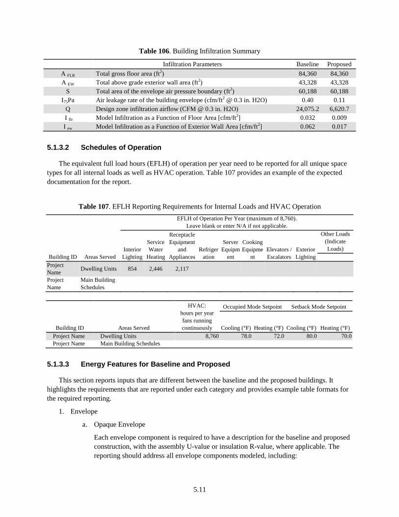
5.11
Table 106. Building Infiltration Summary
Infiltration Parameters Baseline Proposed A FLR Total gross floor area (ft2) 84,360 84,360 A EW Total above grade exterior wall area (ft2) 43,328 43,328
S Total area of the envelope air pressure boundary (ft2) 60,188 60,188 I75Pa Air leakage rate of the building envelope (cfm/ft2 @ 0.3 in. H2O) 0.40 0.11
Q Design zone infiltration airflow (CFM @ 0.3 in. H2O) 24,075.2 6,620.7 I flr Model Infiltration as a Function of Floor Area [cfm/ft2] 0.032 0.009 I ew Model Infiltration as a Function of Exterior Wall Area [cfm/ft2] 0.062 0.017
5.1.3.2 Schedules of Operation
The equivalent full load hours (EFLH) of operation per year need to be reported for all unique space types for all internal loads as well as HVAC operation. Table 107 provides an example of the expected documentation for the report.
Table 107. EFLH Reporting Requirements for Internal Loads and HVAC Operation
Building ID Areas Served
EFLH of Operation Per Year (maximum of 8,760). Leave blank or enter N/A if not applicable.
Interior Lighting
Service Water
Heating
Receptacle Equipment
and Appliances
Refrigeration
Server Equipm
ent
Cooking Equipme
nt Elevators / Escalators
Exterior Lighting
Other Loads (Indicate Loads)
Project Name Dwelling Units 854 2,446 2,117
Project Name
Main Building Schedules
Building ID Areas Served
HVAC: hours per year fans running continuously
Occupied Mode Setpoint Setback Mode Setpoint
Cooling (°F) Heating (°F) Cooling (°F) Heating (°F) Project Name Dwelling Units 8,760 78.0 72.0 80.0 70.0 Project Name Main Building Schedules
5.1.3.3 Energy Features for Baseline and Proposed
This section reports inputs that are different between the baseline and the proposed buildings. It highlights the requirements that are reported under each category and provides example table formats for the required reporting.
1. Envelope
a. Opaque Envelope
Each envelope component is required to have a description for the baseline and proposed construction, with the assembly U-value or insulation R-value, where applicable. The reporting should address all envelope components modeled, including:
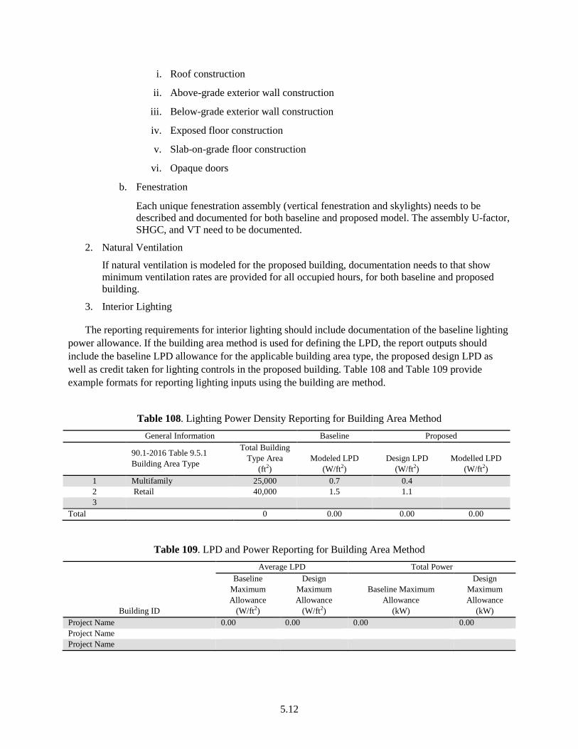
5.12
i. Roof construction
ii. Above-grade exterior wall construction
iii. Below-grade exterior wall construction
iv. Exposed floor construction
v. Slab-on-grade floor construction
vi. Opaque doors
b. Fenestration
Each unique fenestration assembly (vertical fenestration and skylights) needs to be described and documented for both baseline and proposed model. The assembly U-factor, SHGC, and VT need to be documented.
2. Natural Ventilation
If natural ventilation is modeled for the proposed building, documentation needs to that show minimum ventilation rates are provided for all occupied hours, for both baseline and proposed building.
3. Interior Lighting
The reporting requirements for interior lighting should include documentation of the baseline lighting power allowance. If the building area method is used for defining the LPD, the report outputs should include the baseline LPD allowance for the applicable building area type, the proposed design LPD as well as credit taken for lighting controls in the proposed building. Table 108 and Table 109 provide example formats for reporting lighting inputs using the building are method.
Table 108. Lighting Power Density Reporting for Building Area Method General Information Baseline Proposed
90.1-2016 Table 9.5.1 Building Area Type
Total Building Type Area
(ft2) Modeled LPD
(W/ft2) Design LPD
(W/ft2) Modelled LPD
(W/ft2) 1 Multifamily 25,000 0.7 0.4 2 Retail 40,000 1.5 1.1 3
Total 0 0.00 0.00 0.00
Table 109. LPD and Power Reporting for Building Area Method
Building ID
Average LPD Total Power Baseline
Maximum Allowance
(W/ft2)
Design Maximum Allowance
(W/ft2)
Baseline Maximum Allowance
(kW)
Design Maximum Allowance
(kW) Project Name 0.00 0.00 0.00 0.00 Project Name Project Name
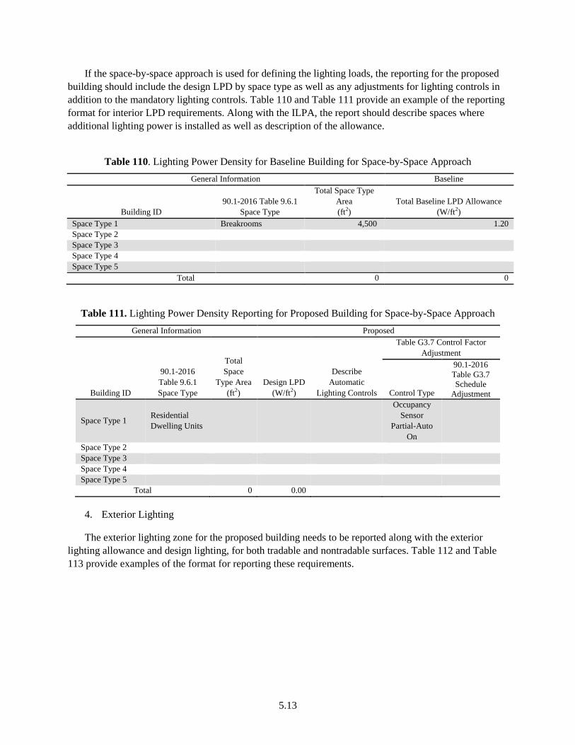
5.13
If the space-by-space approach is used for defining the lighting loads, the reporting for the proposed building should include the design LPD by space type as well as any adjustments for lighting controls in addition to the mandatory lighting controls. Table 110 and Table 111 provide an example of the reporting format for interior LPD requirements. Along with the ILPA, the report should describe spaces where additional lighting power is installed as well as description of the allowance.
Table 110. Lighting Power Density for Baseline Building for Space-by-Space Approach General Information Baseline
Building ID 90.1-2016 Table 9.6.1
Space Type
Total Space Type Area (ft2)
Total Baseline LPD Allowance (W/ft2)
Space Type 1 Breakrooms 4,500 1.20 Space Type 2 Space Type 3 Space Type 4 Space Type 5
Total 0 0
Table 111. Lighting Power Density Reporting for Proposed Building for Space-by-Space Approach General Information Proposed
Building ID
90.1-2016 Table 9.6.1 Space Type
Total Space
Type Area (ft2)
Design LPD (W/ft2)
Describe Automatic
Lighting Controls
Table G3.7 Control Factor Adjustment
Control Type
90.1-2016 Table G3.7 Schedule
Adjustment
Space Type 1 Residential Dwelling Units
Occupancy Sensor
Partial-Auto On
Space Type 2 Space Type 3 Space Type 4 Space Type 5
Total 0 0.00
4. Exterior Lighting
The exterior lighting zone for the proposed building needs to be reported along with the exterior lighting allowance and design lighting, for both tradable and nontradable surfaces. Table 112 and Table 113 provide examples of the format for reporting these requirements.
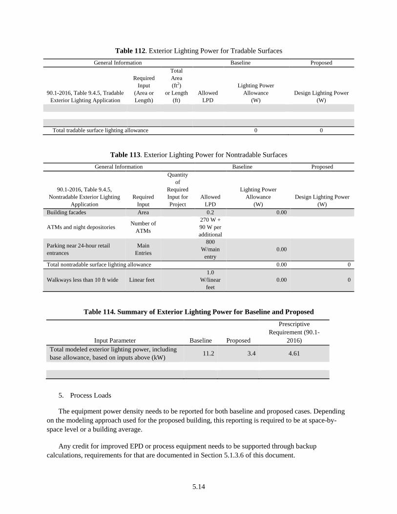
5.14
Table 112. Exterior Lighting Power for Tradable Surfaces General Information Baseline Proposed
90.1-2016, Table 9.4.5, Tradable Exterior Lighting Application
Required Input
(Area or Length)
Total Area (ft2)
or Length (ft)
Allowed LPD
Lighting Power Allowance
(W) Design Lighting Power
(W)
Total tradable surface lighting allowance 0 0
Table 113. Exterior Lighting Power for Nontradable Surfaces General Information Baseline Proposed
90.1-2016, Table 9.4.5, Nontradable Exterior Lighting
Application Required
Input
Quantity of
Required Input for Project
Allowed LPD
Lighting Power Allowance
(W) Design Lighting Power
(W) Building facades Area 0.2 0.00
ATMs and night depositories Number of ATMs
270 W + 90 W per additional
Parking near 24-hour retail entrances
Main Entries
800 W/main
entry 0.00
Total nontradable surface lighting allowance 0.00 0
Walkways less than 10 ft wide Linear feet 1.0
W/linear feet
0.00 0
Table 114. Summary of Exterior Lighting Power for Baseline and Proposed
Input Parameter Baseline Proposed
Prescriptive Requirement (90.1-
2016) Total modeled exterior lighting power, including base allowance, based on inputs above (kW) 11.2 3.4 4.61
5. Process Loads
The equipment power density needs to be reported for both baseline and proposed cases. Depending on the modeling approach used for the proposed building, this reporting is required to be at space-by-space level or a building average.
Any credit for improved EPD or process equipment needs to be supported through backup calculations, requirements for that are documented in Section 5.1.3.6 of this document.
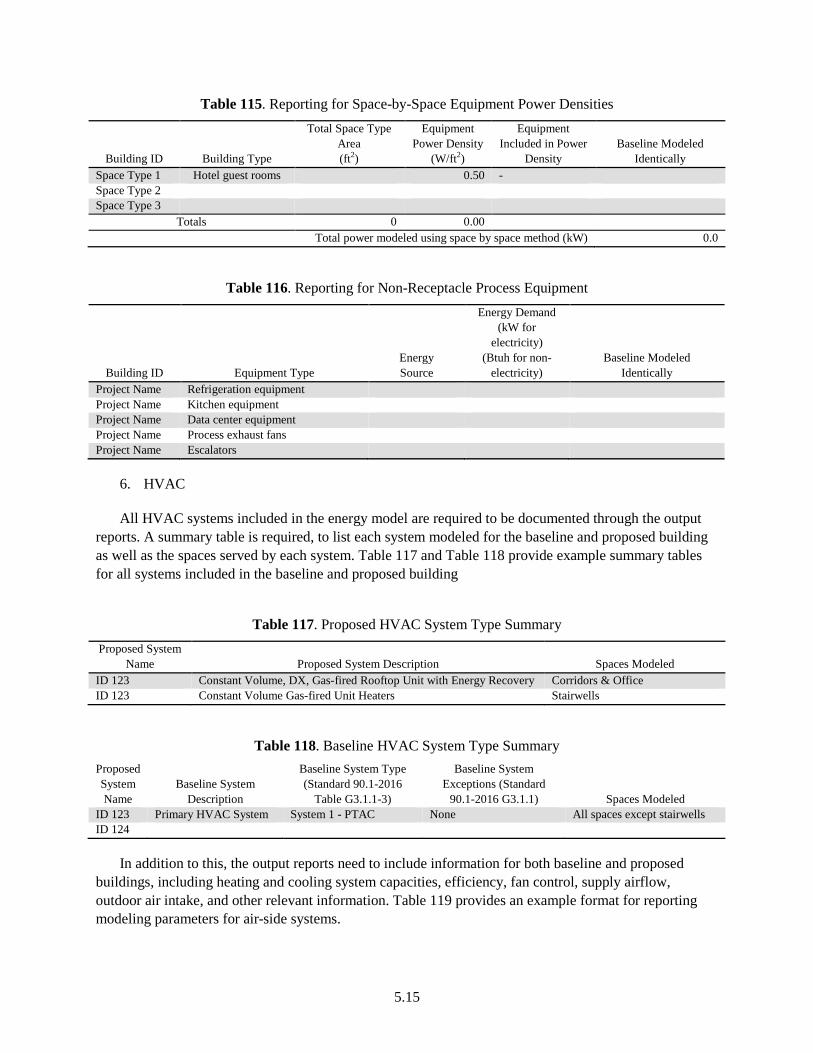
5.15
Table 115. Reporting for Space-by-Space Equipment Power Densities
Building ID Building Type
Total Space Type Area (ft2)
Equipment Power Density
(W/ft2)
Equipment Included in Power
Density Baseline Modeled
Identically Space Type 1 Hotel guest rooms 0.50 - Space Type 2 Space Type 3
Totals 0 0.00 Total power modeled using space by space method (kW) 0.0
Table 116. Reporting for Non-Receptacle Process Equipment
Building ID Equipment Type Energy Source
Energy Demand (kW for
electricity) (Btuh for non-
electricity) Baseline Modeled
Identically Project Name Refrigeration equipment Project Name Kitchen equipment Project Name Data center equipment Project Name Process exhaust fans Project Name Escalators
6. HVAC
All HVAC systems included in the energy model are required to be documented through the output reports. A summary table is required, to list each system modeled for the baseline and proposed building as well as the spaces served by each system. Table 117 and Table 118 provide example summary tables for all systems included in the baseline and proposed building
Table 117. Proposed HVAC System Type Summary Proposed System
Name Proposed System Description Spaces Modeled ID 123 Constant Volume, DX, Gas-fired Rooftop Unit with Energy Recovery Corridors & Office ID 123 Constant Volume Gas-fired Unit Heaters Stairwells
Table 118. Baseline HVAC System Type Summary Proposed System Name
Baseline System Description
Baseline System Type (Standard 90.1-2016
Table G3.1.1-3)
Baseline System Exceptions (Standard
90.1-2016 G3.1.1) Spaces Modeled ID 123 Primary HVAC System System 1 - PTAC None All spaces except stairwells ID 124
In addition to this, the output reports need to include information for both baseline and proposed buildings, including heating and cooling system capacities, efficiency, fan control, supply airflow, outdoor air intake, and other relevant information. Table 119 provides an example format for reporting modeling parameters for air-side systems.
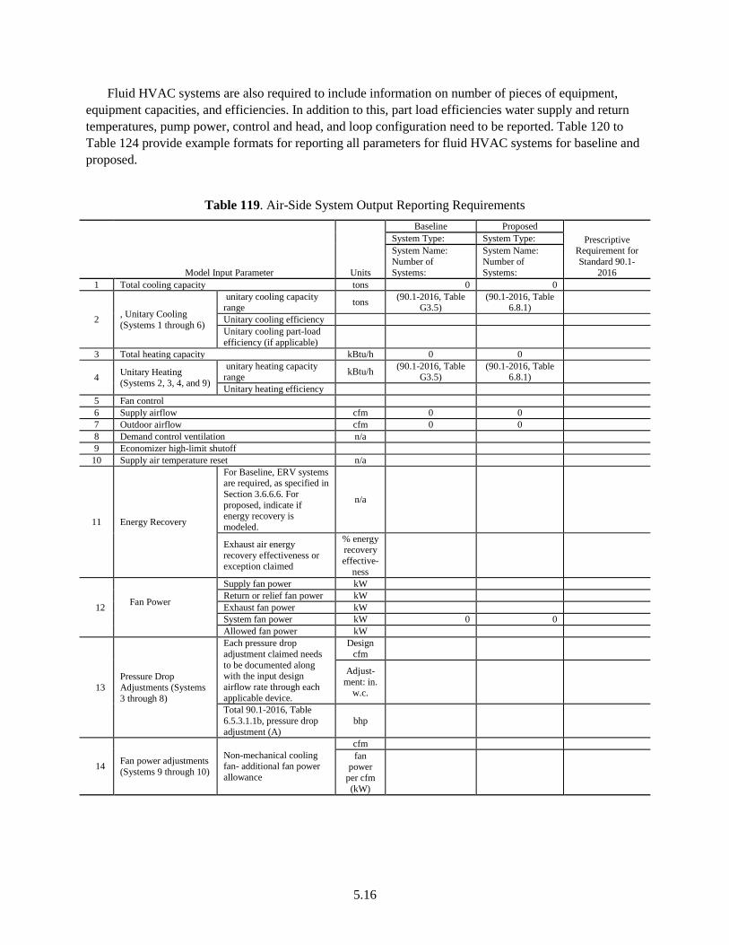
5.16
Fluid HVAC systems are also required to include information on number of pieces of equipment, equipment capacities, and efficiencies. In addition to this, part load efficiencies water supply and return temperatures, pump power, control and head, and loop configuration need to be reported. Table 120 to Table 124 provide example formats for reporting all parameters for fluid HVAC systems for baseline and proposed.
Table 119. Air-Side System Output Reporting Requirements
Model Input Parameter Units
Baseline Proposed Prescriptive
Requirement for Standard 90.1-
2016
System Type: System Type: System Name: Number of Systems:
System Name: Number of Systems:
1 Total cooling capacity tons 0 0
2 , Unitary Cooling (Systems 1 through 6)
unitary cooling capacity range tons (90.1-2016, Table
G3.5) (90.1-2016, Table
6.8.1)
Unitary cooling efficiency Unitary cooling part-load efficiency (if applicable)
3 Total heating capacity kBtu/h 0 0
4 Unitary Heating (Systems 2, 3, 4, and 9)
unitary heating capacity range kBtu/h (90.1-2016, Table
G3.5) (90.1-2016, Table
6.8.1)
Unitary heating efficiency 5 Fan control 6 Supply airflow cfm 0 0 7 Outdoor airflow cfm 0 0 8 Demand control ventilation n/a 9 Economizer high-limit shutoff
10 Supply air temperature reset n/a
11 Energy Recovery
For Baseline, ERV systems are required, as specified in Section 3.6.6.6. For proposed, indicate if energy recovery is modeled.
n/a
Exhaust air energy recovery effectiveness or exception claimed
% energy recovery effective-
ness
12 Fan Power
Supply fan power kW Return or relief fan power kW Exhaust fan power kW System fan power kW 0 0 Allowed fan power kW
13 Pressure Drop Adjustments (Systems 3 through 8)
Each pressure drop adjustment claimed needs to be documented along with the input design airflow rate through each applicable device.
Design cfm
Adjust-ment: in.
w.c.
Total 90.1-2016, Table 6.5.3.1.1b, pressure drop adjustment (A)
bhp
14 Fan power adjustments (Systems 9 through 10)
Non-mechanical cooling fan- additional fan power allowance
cfm fan
power per cfm (kW)
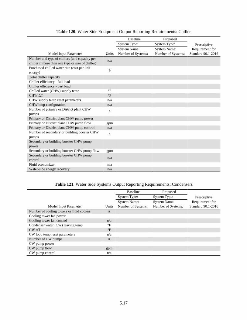
5.17
Table 120. Water Side Equipment Output Reporting Requirements: Chiller
Model Input Parameter Units
Baseline Proposed Prescriptive
Requirement for Standard 90.1-2016
System Type: System Type: System Name: Number of Systems:
System Name: Number of Systems:
Number and type of chillers (and capacity per chiller if more than one type or size of chiller) n/a
Purchased chilled water rate (cost per unit energy) $
Total chiller capacity Chiller efficiency - full load Chiller efficiency - part load Chilled water (CHW) supply temp °F CHW ΔT °F CHW supply temp reset parameters n/a CHW loop configuration n/a Number of primary or District plant CHW pumps #
Primary or District plant CHW pump power Primary or District plant CHW pump flow gpm Primary or District plant CHW pump control n/a Number of secondary or building booster CHW pumps #
Secondary or building booster CHW pump power
Secondary or building booster CHW pump flow gpm Secondary or building booster CHW pump control n/a
Fluid economizer n/a Water-side energy recovery n/a
Table 121. Water Side Systems Output Reporting Requirements: Condensers
Model Input Parameter Units
Baseline Proposed Prescriptive
Requirement for Standard 90.1-2016
System Type: System Type: System Name: Number of Systems:
System Name: Number of Systems:
Number of cooling towers or fluid coolers # Cooling tower fan power Cooling tower fan control n/a Condenser water (CW) leaving temp °F CW ΔT °F CW loop temp reset parameters n/a Number of CW pumps # CW pump power CW pump flow gpm CW pump control n/a
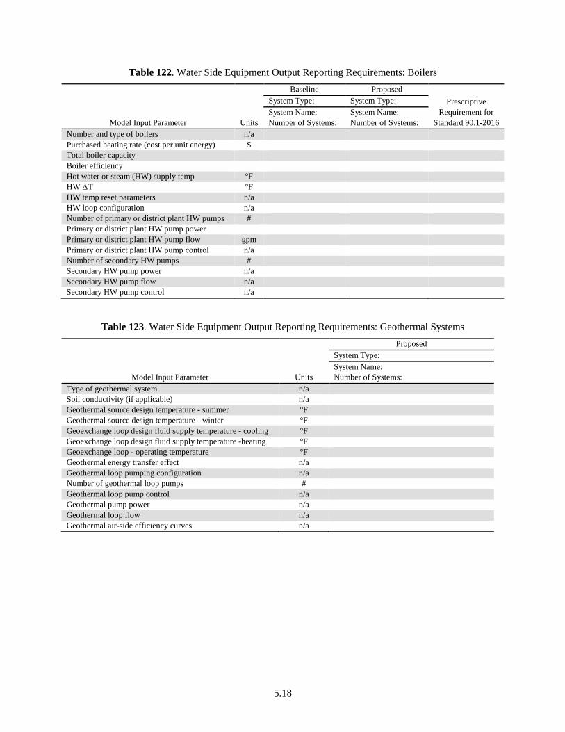
5.18
Table 122. Water Side Equipment Output Reporting Requirements: Boilers
Model Input Parameter Units
Baseline Proposed Prescriptive
Requirement for Standard 90.1-2016
System Type: System Type: System Name: Number of Systems:
System Name: Number of Systems:
Number and type of boilers n/a Purchased heating rate (cost per unit energy) $ Total boiler capacity Boiler efficiency Hot water or steam (HW) supply temp °F HW ΔT °F HW temp reset parameters n/a HW loop configuration n/a Number of primary or district plant HW pumps # Primary or district plant HW pump power Primary or district plant HW pump flow gpm Primary or district plant HW pump control n/a Number of secondary HW pumps # Secondary HW pump power n/a Secondary HW pump flow n/a Secondary HW pump control n/a
Table 123. Water Side Equipment Output Reporting Requirements: Geothermal Systems
Model Input Parameter Units
Proposed System Type: System Name: Number of Systems:
Type of geothermal system n/a Soil conductivity (if applicable) n/a Geothermal source design temperature - summer °F Geothermal source design temperature - winter °F Geoexchange loop design fluid supply temperature - cooling °F Geoexchange loop design fluid supply temperature -heating °F Geoexchange loop - operating temperature °F Geothermal energy transfer effect n/a Geothermal loop pumping configuration n/a Number of geothermal loop pumps # Geothermal loop pump control n/a Geothermal pump power n/a Geothermal loop flow n/a Geothermal air-side efficiency curves n/a
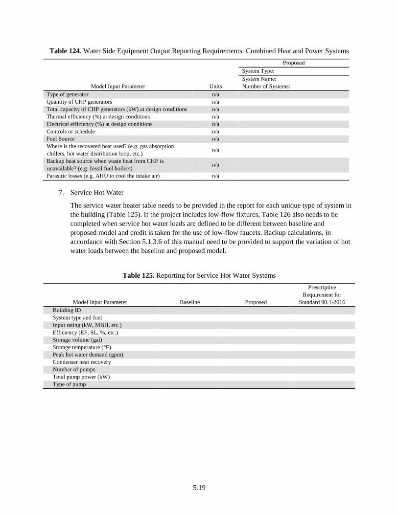
5.19
Table 124. Water Side Equipment Output Reporting Requirements: Combined Heat and Power Systems
Model Input Parameter Units
Proposed System Type: System Name: Number of Systems:
Type of generator n/a Quantity of CHP generators n/a Total capacity of CHP generators (kW) at design conditions n/a Thermal efficiency (%) at design conditions n/a Electrical efficiency (%) at design conditions n/a Controls or schedule n/a Fuel Source n/a Where is the recovered heat used? (e.g. gas absorption chillers, hot water distribution loop, etc.) n/a
Backup heat source when waste heat from CHP is unavailable? (e.g. fossil fuel boilers) n/a
Parasitic losses (e.g. AHU to cool the intake air) n/a
7. Service Hot Water
The service water heater table needs to be provided in the report for each unique type of system in the building (Table 125). If the project includes low-flow fixtures, Table 126 also needs to be completed when service hot water loads are defined to be different between baseline and proposed model and credit is taken for the use of low-flow faucets. Backup calculations, in accordance with Section 5.1.3.6 of this manual need to be provided to support the variation of hot water loads between the baseline and proposed model.
Table 125. Reporting for Service Hot Water Systems
Model Input Parameter Baseline Proposed
Prescriptive Requirement for
Standard 90.1-2016 Building ID System type and fuel Input rating (kW, MBH, etc.) Efficiency (EF, SL, %, etc.) Storage volume (gal) Storage temperature (°F) Peak hot water demand (gpm) Condenser heat recovery Number of pumps Total pump power (kW) Type of pump
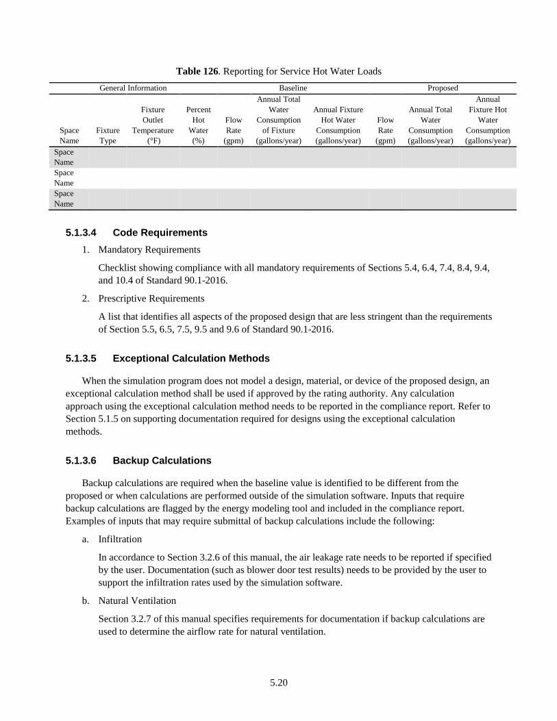
5.20
Table 126. Reporting for Service Hot Water Loads General Information Baseline Proposed
Space Name
Fixture Type
Fixture Outlet
Temperature (°F)
Percent Hot
Water (%)
Flow Rate
(gpm)
Annual Total Water
Consumption of Fixture
(gallons/year)
Annual Fixture Hot Water
Consumption (gallons/year)
Flow Rate
(gpm)
Annual Total Water
Consumption (gallons/year)
Annual Fixture Hot
Water Consumption (gallons/year)
Space Name
Space Name
Space Name
5.1.3.4 Code Requirements 1. Mandatory Requirements
Checklist showing compliance with all mandatory requirements of Sections 5.4, 6.4, 7.4, 8.4, 9.4, and 10.4 of Standard 90.1-2016.
2. Prescriptive Requirements
A list that identifies all aspects of the proposed design that are less stringent than the requirements of Section 5.5, 6.5, 7.5, 9.5 and 9.6 of Standard 90.1-2016.
5.1.3.5 Exceptional Calculation Methods
When the simulation program does not model a design, material, or device of the proposed design, an exceptional calculation method shall be used if approved by the rating authority. Any calculation approach using the exceptional calculation method needs to be reported in the compliance report. Refer to Section 5.1.5 on supporting documentation required for designs using the exceptional calculation methods.
5.1.3.6 Backup Calculations
Backup calculations are required when the baseline value is identified to be different from the proposed or when calculations are performed outside of the simulation software. Inputs that require backup calculations are flagged by the energy modeling tool and included in the compliance report. Examples of inputs that may require submittal of backup calculations include the following:
a. Infiltration
In accordance to Section 3.2.6 of this manual, the air leakage rate needs to be reported if specified by the user. Documentation (such as blower door test results) needs to be provided by the user to support the infiltration rates used by the simulation software.
b. Natural Ventilation
Section 3.2.7 of this manual specifies requirements for documentation if backup calculations are used to determine the airflow rate for natural ventilation.
5.21
c. Exterior Lighting
If exterior lighting schedule for the baseline building differs from the proposed design, the input needs to be reported in the compliance reports. Section 3.3.3 of this manual specifies baseline and proposed building requirements for exterior lighting schedule.
d. Daylighting Control Illumination Setpoint
If the user input for illumination setpoint is above or below the IESNA specification, the input should be flagged and included in the compliance reports. The user is required to provide documentation supporting the specification of illumination setpoint for the proposed design.
e. Elevators, Escalators, and Moving Walkways
Variations of the power requirements, schedules, or control sequences of elevators, escalators, and moving walkways modeled in the baseline building from those in the proposed design need to be included in the compliance reports. The user is required to provide documentation supporting these variations. Section 3.3.7 of this manual specifies requirements for elevators, escalators, and moving walkways.
f. Process and Gas Equipment
Variations of the power requirements, schedules, or control sequences of the gas equipment modeled in the baseline building from those in the proposed design need to be reported in the compliance reports. Section 0 of this document specifies requirements for process and gas equipment.
g. Building Orientation
In accordance with Section 3.4.1 of this manual, the baseline building is not required to be simulated for all four orientations, if the orientation of the proposed design is dictated by site considerations. This exception needs to be reported in the output reports and documentation needs to be provided by the user to support this selection.
h. Service Hot Water Section 3.8.1 of this manual specifies the requirements for service hot water loads. The service hot water loads are required to be the same between the baseline and proposed models, unless credit is taken for a design strategy that reduces the hot water loads in the proposed design. Such an input needs to be flagged and documented in the reports. Backup calculations need to be provided to support the difference in service hot water loads between the baseline and proposed models.
5.1.4 Representations
The representations report will have all relevant building titles and claims. The representations report is generated by the software tool and needs to be certified by the mechanical engineer, energy consultant, architect, and/or owner.
5.22
5.1.5 Supporting Documentation
This section of the report is provided by the user and will include drawings and details supporting the following.
5.1.5.1 Drawings
The report will include detailed architectural and mechanical drawings to support the inputs entered into the energy modeling software, including:
a. A floor plan showing building orientation
b. A site plan showing all adjacent buildings and topography that may shade the proposed building (with estimated height or number of stories)
c. Building elevations and floor plans (schematic is acceptable)
d. A diagram showing the thermal blocks used in the computer simulation
5.1.5.2 Exceptional Calculation Methods
The Model Input Documentations section reports inputs that claim to use exceptional calculation methods. The user needs to provide a narrative explaining the exceptional calculation method performed, and theoretical or empirical information supporting the accuracy of the method. The calculations shall be performed on a time step basis consistent with the simulation program used. All applications for approval of an exceptional method shall include:
a. Step-by-step documentation of the exceptional calculation method performed that is detailed enough to reproduce the results
b. Copies of all spreadsheets used to perform the calculations
c. A sensitivity analysis of energy consumption when each of the input parameters is varied from half to double the value assumed
d. The performance rating results calculated with and without the exceptional calculation method
e. Backup calculations
5.2 Format of Report
The energy modeling software will produce an XML file and PDF reports. Spreadsheets can be used to support the exceptional calculation method or the backup calculations.
6.1
6.0 References
ANSI/ASHRAE. 2013d. ANSI/ASHRAE Standard 170-2013, Ventilation of Health Care Facilities. American Society of Heating, Refrigerating and Air-Conditioning Engineers, Atlanta, Georgia
ANSI/ASHRAE. 2013c. ANSI/ASHRAE Standard 55-2013, Thermal Environmental Conditions for Human Occupancy. American Society of Heating, Refrigerating and Air-Conditioning Engineers, Atlanta, Georgia.
ANSI/ASHRAE (2004). ANSI/ASHRAE Standard 62.1-2004, Ventilation for Acceptable Indoor Air Quality. American Society of Heating, Refrigerating and Air-Conditioning Engineers, Atlanta, Georgia.
ANSI/ASHRAE (2007). ANSI/ASHRAE Standard 62.1-2007, Ventilation for Acceptable Indoor Air Quality. American Society of Heating, Refrigerating and Air-Conditioning Engineers, Atlanta, Georgia.
ANSI/ASHRAE (2013b). ANSI/ASHRAE Standard 62.1-2013, Ventilation for Acceptable Indoor Air Quality. American Society of Heating, Refrigerating and Air-Conditioning Engineers, Atlanta, Georgia.
ANSI/ASHRAE/IES (2010). ANSI/ASHRAE/IES 90.1-2010, Energy Standard for Buildings Except Low-Rise Residential Buildings. American Society of Heating, Refrigerating and Air-Conditioning Engineers, Atlanta, Georgia.
ANSI/ASHRAE/IES (2013). ANSI/ASHRAE/IES 90.1-2013, Energy Standard for Buildings Except Low-Rise Residential Buildings. American Society of Heating, Refrigerating and Air-Conditioning Engineers, Atlanta, Georgia.
ANSI/ASHRAE/IES (2016). ANSI/ASHRAE/IES 90.1-2016, Energy Standard for Buildings Except Low-Rise Residential Buildings. American Society of Heating, Refrigerating and Air-Conditioning Engineers, Atlanta, Georgia.
ASHRAE (2009). Handbook of Fundamentals. American Society of Heating, Refrigerating and Air-Conditioning Engineers, Atlanta, Georgia.
ASHRAE (2017). Handbook of Fundamentals. American Society of Heating, Refrigerating and Air-Conditioning Engineers, Atlanta, Georgia.
ASTM (2010). ASTM E779, Standard Test Method for Determining Air Leakage Rate by Fan Pressurization. American Society for Testing and Materials, West Conshohocken, Pennsylvania.
CEC - California Energy Commission (2013b). 2013Building Energy Efficiency Standards. California Energy Commission, Sacramento, CA.
CEC - California Energy Commission (2013). 2013 Nonres ACM Reference Listing. Retrieved October 8, 2015, from ca.gov: http://www.energy.ca.gov/title24/2013standards/implementation/documents/ 2013_nonres_ACM_reference/.
6.2
CEC - California Energy Commission (2016). 2016 Nonres ACM Reference Listing. Retrieved September 5, 2017, from ca.gov: http://www.energy.ca.gov/2015publications/CEC-400-2015-037/CEC-400-2015-037-CMF.pdf.
COMNET (2017). Retrieved from Commercial Buildings Energy Modeling Guidelines & Procedures: http://www.comnet.org/reference-appendices
De Soto, W., Klein, S. A., & Beckman, W. A. (2006). “Improvement and validation of a model for photovoltaic array performance.” Solar Energy 80(1):78-88.
IMC (2012). International Mechanical Code 2012. International Code Council. https://codes.iccsafe.org/public/document/code/287/4962363
IMC (2015). International Mechanical Code 2015. International Code Council. https://codes.iccsafe.org/public/document/code/549/9788963
PRM-RM 2010. ANSI/ASHRAE/IES Standard 90.1-2010 Performance Rating Method Reference Manual, PNNL-25130 http://www.pnnl.gov/main/publications/external/technical_reports/PNNL-25130.pdf
Rosenberg, M., & Hart R. (2016) Developing Performance Cost Index Targets for ASHRAE Standard 90.1 Appendix G - Performance Rating Method. PPNNL-25202-Rev1. Pacific Northwest National Laboratory, Richland, Washington. http://www.pnnl.gov/main/publications/external/technical_reports/PNNL-25202Rev1.pdf
Thornton, B.A, M Rosenberg, EE Richman, W Wang, Y Xie, J Zhang, H Cho, VV Mendon, RA Athalye, and B Liu. 2011. Achieving the 30% Goal: Energy and Cost Savings Analysis of ASHRAE Standard 90.1-2010. PNNL-20405, Pacific Northwest National Laboratory, Richland, Washington. http://www.pnl.gov/main/publications/external/technical_reports/PNNL-20405.pdf
Trane (2016). https://www.trane.com/Commercial/Uploads/PDF/11598/News-%20Free%20Cooling%20using%20Water%20Economizers.pdf. Accessed on June, 2017.
Tregenza P., & Waters, I. (1983). “Daylight coefficients.” Lighting Research and Technology 15(2):65- 71.
USDOE (2015). EnergyPlus. http://energyplus.net. Content last updated February 4, 2015. Winkelmann, F., & S. Selkowitz, S. (1985). Daylighting Simulation in DOE-2: Theory, Application, Validation and Applications. LBL-19829, Lawrence Berkeley Laboratory, Berkeley, California. http://simulationresearch.lbl.gov/dirpubs/19829.pdf.