Embed Size (px)
Citation preview
ANSI/ASHRAE/IES Addenda a, c, d, e, g, h, j, k, m, n, o, p, q, r, s, z,aa, ac, ad, ae, ag, ak, bm, and dx to
ANSI/ASHRAE/IES Standard 90.1-2013
Energy Standardfor Buildings
Except Low-RiseResidential Buildings
(I-P and SI)
See Appendix A for approval dates.
These addenda were approved by a Standing Standard Project Committee (SSPC) for which the Standards Committee has estab-lished a documented program for regular publication of addenda or revisions, including procedures for timely, documented, con-sensus action on requests for change to any part of the standard. The change submittal form, instructions, and deadlines may beobtained in electronic form from the ASHRAE website (www.ashrae.org) or in paper form from the Senior Manager of Standards.
The latest edition of an ASHRAE Standard may be purchased on the ASHRAE website (www.ashrae.org) or from ASHRAE Cus-tomer Service, 1791 Tullie Circle, NE, Atlanta, GA 30329-2305. E-mail: [email protected]. Fax: 678-539-2129. Telephone: 404-636-8400 (worldwide), or toll free 1-800-527-4723 (for orders in US and Canada). For reprint permission, go towww.ashrae.org/permissions.
© 2015 ASHRAE ISSN 1041-2336
2015 Supplement
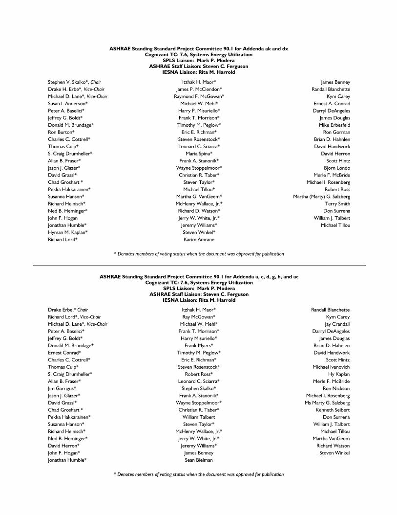
ASHRAE Standing Standard Project Committee 90.1 for Addenda ak and dxCognizant TC: 7.6, Systems Energy Utilization
SPLS Liaison: Mark P. ModeraASHRAE Staff Liaison: Steven C. Ferguson
IESNA Liaison: Rita M. Harrold
Stephen V. Skalko*, Chair Itzhak H. Maor* James BenneyDrake H. Erbe*, Vice-Chair James P. McClendon* Randall BlanchetteMichael D. Lane*, Vice-Chair Raymond F. McGowan* Kym CareySusan I. Anderson* Michael W. Mehl* Ernest A. ConradPeter A. Baselici* Harry P. Misuriello* Darryl DeAngelesJeffrey G. Boldt* Frank T. Morrison* James DouglasDonald M. Brundage* Timothy M. Peglow* Mike ErbesfeldRon Burton* Eric E. Richman* Ron GormanCharles C. Cottrell* Steven Rosenstock* Brian D. HahnlenThomas Culp* Leonard C. Sciarra* David HandworkS. Craig Drumheller* Maria Spinu* David HerronAllan B. Fraser* Frank A. Stanonik* Scott HintzJason J. Glazer* Wayne Stoppelmoor* Bjorn LondoDavid Grassl* Christian R. Taber* Merle F. McBrideChad Groshart * Steven Taylor* Michael I. RosenbergPekka Hakkarainen* Michael Tillou* Robert RossSusanna Hanson* Martha G. VanGeem* Martha (Marty) G. SalzbergRichard Heinisch* McHenry Wallace, Jr.* Terry SmithNed B. Heminger* Richard D. Watson* Don SurrenaJohn F. Hogan Jerry W. White, Jr.* William J. TalbertJonathan Humble* Jeremy Williams* Michael TillouHyman M. Kaplan* Steven Winkel*Richard Lord* Karim Amrane
* Denotes members of voting status when the document was approved for publication
ASHRAE Standing Standard Project Committee 90.1 for Addenda a, c, d, g, h, and acCognizant TC: 7.6, Systems Energy Utilization
SPLS Liaison: Mark P. ModeraASHRAE Staff Liaison: Steven C. Ferguson
IESNA Liaison: Rita M. Harrold
Drake Erbe,* Chair Itzhak H. Maor* Randall BlanchetteRichard Lord*, Vice-Chair Ray McGowan* Kym CareyMichael D. Lane*, Vice-Chair Michael W. Mehl* Jay CrandallPeter A. Baselici* Frank T. Morrison* Darryl DeAngelesJeffrey G. Boldt* Harry Misuriello* James DouglasDonald M. Brundage* Frank Myers* Brian D. HahnlenErnest Conrad* Timothy M. Peglow* David HandworkCharles C. Cottrell* Eric E. Richman* Scott HintzThomas Culp* Steven Rosenstock* Michael IvanovichS. Craig Drumheller* Robert Ross* Hy KaplanAllan B. Fraser* Leonard C. Sciarra* Merle F. McBrideJim Garrigus* Stephen Skalko* Ron NicksonJason J. Glazer* Frank A. Stanonik* Michael I. RosenbergDavid Grassl* Wayne Stoppelmoor* Ms Marty G. SalzbergChad Groshart * Christian R. Taber* Kenneth SeibertPekka Hakkarainen* William Talbert Don SurrenaSusanna Hanson* Steven Taylor* William J. TalbertRichard Heinisch* McHenry Wallace, Jr.* Michael TillouNed B. Heminger* Jerry W. White, Jr.* Martha VanGeemDavid Herron* Jeremy Williams* Richard WatsonJohn F. Hogan* James Benney Steven WinkelJonathan Humble* Sean Bielman
* Denotes members of voting status when the document was approved for publication
ASHRAE Standing Standard Project Committee 90.1 for Addenda e, j, k, m, n, o, p, q, r, s, z, a, ad, ae, af, ag, bmCognizant TC: Systems Energy Utilization
SPLS Liaison: Mark ModeraASHRAE Staff Liaison: Steven C. Ferguson
IES Liaison: Rita M. Harrold
Drake Erbe,* Chair Timothy M. Peglow* Gary AshMichael D. Lane,* Vice-Chair Eric E. Richman* Joseph BrooksRichard Lord*, Vice-Chair Robert Ross* Don BrundagePeter A. Baselici* Leonard C. Sciarra* Jay CrandallJeffrey G. Boldt* Wayne Stoppelmoor* James DouglasThomas Culp* Christian R. Taber* Antonio GiacobbeJim Garrigus* William Talbert* Stan HarbuckJason J. Glazer* Steven Taylor* Michael IvanovichDavid Grassl* Martha VanGeem* Hy KaplanPekka Hakkarainen* McHenry Wallace, Jr.* Neil LeslieSusanna Hanson* Jerry W. White, Jr.* Merle F. McBrideRichard Heinisch* Ernest Conrad* Benjamin MeyerNed B. Heminger* Charles C. Cottrell* Ron NicksonScott Hintz* S. Craig Drumheller* Mark NowakJohn F. Hogan* Chad Groshart * Michael I. RosenbergJonathan Humble* Ray McGowan* Marty G. SalzbergItzhak H. Maor* Harry Misuriello* Amy SchmidtChris Mathis* Steven Rosenstock* Kelly SeegerMichael W. Mehl* Frank A. Stanonik* Don SurrenaFrank T. Morrison* Jeremy Williams* Michael TillouFrank Myers* Karim Amrane Richard Watson
* Denotes members of voting status when the document was approved for publication
ASHRAE STANDARDS COMMITTEE 2015–2016
Douglass T. Reindl, Chair Keith I. Emerson Heather L. PlattRita M. Harrold, Vice-Chair Steven J. Emmerich David RobinJoseph R. Anderson Julie M. Ferguson Peter SimmondsJames D. Aswegan Roger L. Hedrick Dennis A. StankeNiels Bidstrup Srinivas Katipamula Wayne H. Stoppelmoor, Jr.Donald M. Brundage Rick A. Larson Jack H. ZarourJohn A. Clark Lawrence C. Markel Julia A. Keen, BOD ExOWaller S. Clements Arsen K. Melikov James K. Vallort, COJohn F. Dunlap Mark P. ModeraJames W. Earley, Jr. Cyrus H. Nasseri
Stephanie C. Reiniche, Senior Manager of Standards
SPECIAL NOTEThis American National Standard (ANS) is a national voluntary consensus Standard developed under the auspices of ASHRAE. Consensus is defined by theAmerican National Standards Institute (ANSI), of which ASHRAE is a member and which has approved this Standard as an ANS, as “substantial agreementreached by directly and materially affected interest categories. This signifies the concurrence of more than a simple majority, but not necessarily unanimity.Consensus requires that all views and objections be considered, and that an effort be made toward their resolution.” Compliance with this Standard isvoluntary until and unless a legal jurisdiction makes compliance mandatory through legislation.
ASHRAE obtains consensus through participation of its national and international members, associated societies, and public review.ASHRAE Standards are prepared by a Project Committee appointed specifically for the purpose of writing the Standard. The Project Committee
Chair and Vice-Chair must be members of ASHRAE; while other committee members may or may not be ASHRAE members, all must be technicallyqualified in the subject area of the Standard. Every effort is made to balance the concerned interests on all Project Committees.
The Senior Manager of Standards of ASHRAE should be contacted fora. interpretation of the contents of this Standard,b. participation in the next review of the Standard,c. offering constructive criticism for improving the Standard, ord. permission to reprint portions of the Standard.
DISCLAIMERASHRAE uses its best efforts to promulgate Standards and Guidelines for the benefit of the public in light of available information and accepted industrypractices. However, ASHRAE does not guarantee, certify, or assure the safety or performance of any products, components, or systems tested, installed,or operated in accordance with ASHRAE’s Standards or Guidelines or that any tests conducted under its Standards or Guidelines will be nonhazardous orfree from risk.
ASHRAE INDUSTRIAL ADVERTISING POLICY ON STANDARDSASHRAE Standards and Guidelines are established to assist industry and the public by offering a uniform method of testing for rating purposes, by suggestingsafe practices in designing and installing equipment, by providing proper definitions of this equipment, and by providing other information that may serve toguide the industry. The creation of ASHRAE Standards and Guidelines is determined by the need for them, and conformance to them is completely voluntary.In referring to this Standard or Guideline and in marking of equipment and in advertising, no claim shall be made, either stated or implied, that the product
has been approved by ASHRAE.
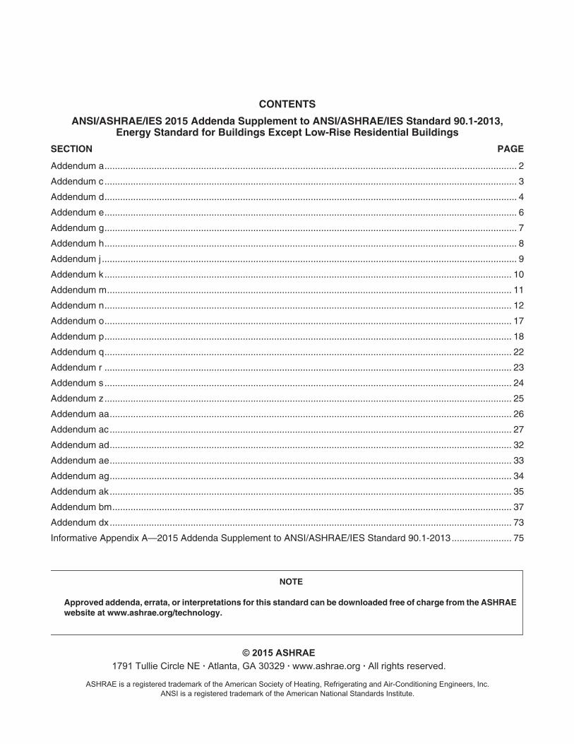
CONTENTS
ANSI/ASHRAE/IES 2015 Addenda Supplement to ANSI/ASHRAE/IES Standard 90.1-2013,Energy Standard for Buildings Except Low-Rise Residential Buildings
SECTION PAGE
Addendum a.............................................................................................................................................................. 2
Addendum c.............................................................................................................................................................. 3
Addendum d.............................................................................................................................................................. 4
Addendum e.............................................................................................................................................................. 6
Addendum g.............................................................................................................................................................. 7
Addendum h.............................................................................................................................................................. 8
Addendum j............................................................................................................................................................... 9
Addendum k............................................................................................................................................................ 10
Addendum m........................................................................................................................................................... 11
Addendum n............................................................................................................................................................ 12
Addendum o............................................................................................................................................................ 17
Addendum p............................................................................................................................................................ 18
Addendum q............................................................................................................................................................ 22
Addendum r ............................................................................................................................................................ 23
Addendum s............................................................................................................................................................ 24
Addendum z............................................................................................................................................................ 25
Addendum aa.......................................................................................................................................................... 26
Addendum ac.......................................................................................................................................................... 27
Addendum ad.......................................................................................................................................................... 32
Addendum ae.......................................................................................................................................................... 33
Addendum ag.......................................................................................................................................................... 34
Addendum ak.......................................................................................................................................................... 35
Addendum bm......................................................................................................................................................... 37
Addendum dx.......................................................................................................................................................... 73
Informative Appendix A—2015 Addenda Supplement to ANSI/ASHRAE/IES Standard 90.1-2013....................... 75
NOTE
Approved addenda, errata, or interpretations for this standard can be downloaded free of charge from the ASHRAEwebsite at www.ashrae.org/technology.
© 2015 ASHRAE
1791 Tullie Circle NE · Atlanta, GA 30329 · www.ashrae.org · All rights reserved.
ASHRAE is a registered trademark of the American Society of Heating, Refrigerating and Air-Conditioning Engineers, Inc.ANSI is a registered trademark of the American National Standards Institute.
2 ANSI/ASHRAE/IES Addendum a to ANSI/ASHRAE/IES Standard 90.1-2013
(This foreword is not part of this standard. It is merelyinformative and does not contain requirements necessaryfor conformance to the standard. It has not been pro-cessed according to the ANSI requirements for a standardand may contain material that has not been subject topublic review or a consensus process. Unresolved objec-tors on informative material are not offered the right toappeal at ASHRAE or ANSI.)
FOREWORD
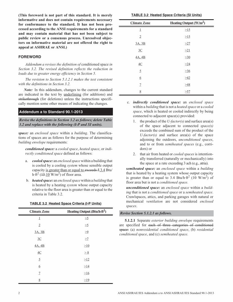
Addendum a revises the definition of conditioned space inSection 3.2. The revised definition reflects the reduction inloads due to greater energy efficiency in Section 5.
The revision to Section 5.1.2.1 makes the text consistentwith the definitions in Section 3.2.
Note: In this addendum, changes to the current standardare indicated in the text by underlining (for additions) andstrikethrough (for deletions) unless the instructions specifi-cally mention some other means of indicating the changes.
space: an enclosed space within a building. The classifica-tions of spaces are as follows for the purpose of determiningbuilding envelope requirements:
conditioned space: a cooled space, heated space, or indi-rectly conditioned space defined as follows:
a. cooled space: an enclosed space within a building thatis cooled by a cooling system whose sensible outputcapacity is greater than or equal to exceeds 5 3.4 Btu/h·ft2 (15 10 W/m2) of floor area.
b. heated space: an enclosed space within a building thatis heated by a heating system whose output capacityrelative to the floor area is greater than or equal to thecriteria in Table 3.2.
c. indirectly conditioned space: an enclosed spacewithin a building that is not a heated space or a cooledspace, which is heated or cooled indirectly by beingconnected to adjacent space(s) provided:1. the product of the U-factor(s) and surface area(s)
of the space adjacent to connected space(s)exceeds the combined sum of the product of theU-factor(s) and surface area(s) of the spaceadjoining the outdoors, unconditioned spaces,and to or from semiheated spaces (e.g., corri-dors) or
2. that air from heated or cooled spaces is intention-ally transferred (naturally or mechanically) intothe space at a rate exceeding 3 ach (e.g., atria).
semiheated space: an enclosed space within a buildingthat is heated by a heating system whose output capacityis greater than or equal to 3.4 Btu/h·ft2 (10 W/m2) offloor area but is not a conditioned space.unconditioned space: an enclosed space within a build-ing that is not a conditioned space or a semiheated space.Crawlspaces, attics, and parking garages with natural ormechanical ventilation are not considered enclosedspaces.
5.1.2.1 Separate exterior building envelope requirementsare specified for each of three categories of conditionedspace: (a) nonresidential conditioned space, (b) residentialconditioned space, and (c) semiheated space.
Addendum a to Standard 90.1-2013
Revise the definitions in Section 3.2 as follows; delete Table3.2 and replace with the following (I-P and SI units).
TABLE 3.2 Heated Space Criteria (I-P Units)
Climate Zone Heating Output (Btu/h·ft2)
1 >5
2 >5
3A, 3B >9
3C >7
4A, 4B >10
4C > 8
5 >12
6 >14
7 >16
8 >19
TABLE 3.2 Heated Space Criteria (SI Units)
Climate Zone Heating Output (W/m2)
1 >15
2 >15
3A, 3B >27
3C >21
4A, 4B >30
4C >24
5 >36
6 >42
7 >48
8 >57
Revise Section 5.1.2.1 as follows.
ANSI/ASHRAE/IES Addendum c to ANSI/ASHRAE/IES Standard 90.1-2013 3
(This foreword is not part of this standard. It is merelyinformative and does not contain requirements necessaryfor conformance to the standard. It has not been pro-cessed according to the ANSI requirements for a standardand may contain material that has not been subject topublic review or a consensus process. Unresolved objec-tors on informative material are not offered the right toappeal at ASHRAE or ANSI.)
FOREWORD
Section 8.4.1 previously separated feeder conductorsfrom branch circuits when limiting voltage drop. By specify-ing the same combined voltage drop over the combination ofcomponents, this addendum reduces first costs in certain proj-ects while remaining neutral on energy costs.
Note: In this addendum, changes to the current standardare indicated in the text by underlining (for additions) andstrikethrough (for deletions) unless the instructions specifi-cally mention some other means of indicating the changes.
8.4 Mandatory Provisions8.4.1 Voltage DropException: Feeder conductors and branch circuits that are
dedicated to emergency services
8.4.1.1 Feeders. Feeder conductors shall be sized for amaximum voltage drop of 2% at design load.
8.4.1.2 Branch Circuits. Branch circuit conductors shallbe sized for a maximum voltage drop of 3% at design load.
8.4.1 Voltage Drop. The conductors for feeders and branchcircuits combined shall be sized for a maximum of 5% volt-age drop total.
Addendum c to Standard 90.1-2013
Modify the standard as follows (I-P and SI units).
(This foreword is not part of this standard. It is merelyinformative and does not contain requirements necessaryfor conformance to the standard. It has not been pro-cessed according to the ANSI requirements for a standardand may contain material that has not been subject topublic review or a consensus process. Unresolved objec-tors on informative material are not offered the right toappeal at ASHRAE or ANSI.)
FOREWORD
This addendum adds deeper thermostat setups and set-backs and ventilation control to unrented hotel guestroomsand more clarity to the existing hotel guestroom requirements.These deeper setups and setbacks will provide additionalenergy savings without affecting occupant comfort. The tech-nology exists from multiple manufacturers to allow for thesereductions in unrented guestrooms. For stand-alone controls,rooms are considered unrented if they are unoccupied for lon-ger than 16 hours. For systems connected to a networkedguest room control, the control can be configured to indicatewhether the room is scheduled to be occupied; thus setbacksand ventilation can be turned off earlier when the room isscheduled to be unoccupied, and the networked control canreturn setpoints to their default levels 60 minutes in advanceof scheduled check-in.
This addendum also requires that ventilation air to theroom be shut off during unoccupied periods. The addendumincludes an exception for a “purge cycle” that would provideventilation air to the guest room one hour before scheduledcheck-in to the room as indicated by a networked guest roomcontrol or through a timed outdoor air ventilation purge cycleone hour per day. It is unclear if shutting off the ventilationair during vacancy complies with ASHRAE Standard 62.1, asthe 62.1 requirements regarding ventilation of unoccupiedspaces are not clear. In addition, a proposal to change Stan-dard 62.1 to allow ventilation to be shut off in response tosensed vacancy is being developed (in the form of ASHRAEStandard 62.1 addendum p) that would clearly allow therequirements contained in this addendum. However, the purgecycle exception allowed by this addendum would allow forenhanced indoor air quality beyond the requirements of Stan-dard 62.1, while still capturing the majority of the energy sav-ings of the ventilation shut-off for the rest of the day. Thecontrols would typically operate from an occupancy sensor,so that cleaning crews in unrented rooms would receive venti-lation necessary during cleaning.
An analysis of the small hotel prototypes results in sav-ings and paybacks that meet ASHRAE SSPC 90.1 scalarthresholds for cost effectiveness for all climate zones for sys-tems where the ventilation fan is simply switched off, such asPTACs. For central ventilation and exhaust systems typicallyprovided with fan coil-units, there is some additional cost forventilation and exhaust dampers and pressure regulationdevices. Even with these added costs, the proposed measuremeets the SSPC 90.1 cost-effectiveness criteria. The situationwhere an energy recovery ventilation device is required was
investigated, and it was found that the measure meets thecost-effective criteria even with reduced savings accountingfor this measure.
Note: In this addendum, changes to the current standardare indicated in the text by underlining (for additions) andstrikethrough (for deletions) unless the instructions specifi-cally mention some other means of indicating the changes.
networked guest room control system: a control system,accessible from the hotel/motel front desk or other centrallocation, that is capable of identifying reserved rooms accord-ing to a timed schedule, and is capable of controlling HVACin each hotel/motel guest room separately.
k. Systems serving hotel/motel guest rooms shall complywith Section 6.4.3.3.5.
6.4.3.3.5 Automatic Control of HVAC in Hotel/MotelGuest Rooms. In hotels and motels with greater than 50 guestrooms, automatic controls for the HVAC equipment servingeach guest room shall be configured according to the require-ments in the following subsection.
6.4.3.3.5.1 Guest Room HVAC Setpoint Control.Within 30 minutes of all occupants leaving the guest room,HVAC setpoints shall be automatically raised by at least 4°F(2°C) from the occupant setpoint in the cooling mode andautomatically lowered by at least 4°F (2°C) from the occu-pant setpoint in the heating mode. When the guest room isunrented and unoccupied, HVAC setpoints shall be automati-cally reset to 80°F (27°C) or higher in the cooling mode andto 60°F (16°C) or lower in the heating mode. Unrented andunoccupied guest rooms shall be determined by either of thefollowing:
a. The guest room has been continuously unoccupied for upto 16 hours.
b. A networked guest room control system indicates theguest room is unrented and the guest room is unoccupiedfor no more than 30 minutes.
Exceptions:
1. A networked guest room control system shall bepermitted to return the thermostat setpoints totheir default occupied setpoints 60 minutesprior to the time the room is scheduled to beoccupied.
2. Cooling for humidity control shall be permittedduring unoccupied periods.
6.4.3.3.5.2 Guest Room Ventilation Control. Within30 minutes of all occupants leaving the guest room, ventila-tion and exhaust fans shall automatically be turned off or iso-
Addendum d to Standard 90.1-2013
Modify Section 3.2 as follows (for both I-P and SI units).
Modify Section 6.3.2 as follows, renumbering the existingitems k through r accordingly (for both I-P and SI units).
Add Section 6.4.3.3.5 as follows (for both I-P and SI units).
4 ANSI/ASHRAE/IES Addendum d to ANSI/ASHRAE/IES Standard 90.1-2013
lation devices serving each guest room shall automaticallyshut off the supply of outdoor air to the guest room and shutoff exhaust air from the guest room.
Exceptions: Guest room ventilation systems shall bepermitted to have an automatic daily preoccupancypurge cycle that provides daily outdoor air ventila-
tion during unrented periods at the design ventila-tion rate for 60 minutes, or at a rate and durationequivalent to one air change.
6.4.3.3.5.3 Automatic Control. Captive key card sys-tems shall be permitted to be used to comply with Section6.4.3.3.5.
ANSI/ASHRAE/IES Addendum d to ANSI/ASHRAE/IES Standard 90.1-2013 5
6 ANSI/ASHRAE/IES Addendum e to ANSI/ASHRAE/IES Standard 90.1-2013
(This foreword is not part of this standard. It is merelyinformative and does not contain requirements necessaryfor conformance to the standard. It has not been pro-cessed according to the ANSI requirements for a standardand may contain material that has not been subject topublic review or a consensus process. Unresolved objec-tors on informative material are not offered the right toappeal at ASHRAE or ANSI.)
FOREWORD
Current requirements for existing building alterationsdon’t require compliance with most mandatory controlrequirements even if it is a major alteration (e.g., gutting thespace or building). Major renovations of lighting shouldrequire the same compliance as new construction. Further-more, Standard 90.1 lags behind the major codes in thisarena. Title 24 2013 requires compliance with all the controlrequirements (in most cases) when more than 10% of thelighting is changed or more than 40 luminaires are modified-in-place. IECC 2012 requires compliance with all the controlrequirements when more than 50% of the lighting load isaltered.
This addendum relaxes the existing threshold somewhat(20% instead of 10%) but captures high energy efficiency byrequiring more of the control requirements. The cost of light-ing controls has decreased and can probably be expected todecrease further, so the addition of these lighting controls inan alteration no longer represents a large barrier
In this addendum, changes to the current standard areindicated in the text by underlining (for additions) and strike-through (for deletions) unless the instructions specificallymention some other means of indicating the changes.
9.1.2 Lighting Alterations. For the alteration of any light-ing system in an interior space, that space shall comply withthe lighting power density (LPD) requirements of Section9.5.1 or 9.6.1 and the control requirements of Sections 9.4.1.1(a), (b), (c), (d), (g), (h), and (i), as applicable to that space.and the automatic shutoff requirements of Section 9.4.1.1.
For the alteration of any lighting system in an exteriorbuilding application, that lighting system shall comply withthe lighting power density (LPD) requirements of Section 9applicable to the area illuminated by that lighting system andthe applicable control requirements of Sections 9.4.21.7(a)and 9.4.1.47(b). Such alterations shall include all luminairesthat are added, replaced or removed. This requirement shallalso be met for alterations that involve only the replacementof lamps plus ballasts. Alterations do not include routinemaintenance or repair situations.
Exception(s):
1. Alterations that involve 20% or less than 10% of theconnected lighting load in a space or area need notcomply with these requirements, provided that suchalterations do not increase the installed LPD.
2. Lighting alterations that only involve replacement oflamps plus ballasts or only involve one-for-one lumi-naire replacement need only comply with LPDrequirement and Section 9.4.1.1(h) or 9.4.1.1(i).
3. Routine maintenance or repair situations.
Addendum e to Standard 90.1-2013
Modify the standard as follows (IP and SI units)
ANSI/ASHRAE/IES Addendum g to ANSI/ASHRAE/IES Standard 90.1-2013 7
(This foreword is not part of this standard. It is merelyinformative and does not contain requirements necessaryfor conformance to the standard. It has not been pro-cessed according to the ANSI requirements for a standardand may contain material that has not been subject topublic review or a consensus process. Unresolved objec-tors on informative material are not offered the right toappeal at ASHRAE or ANSI.)
FOREWORD
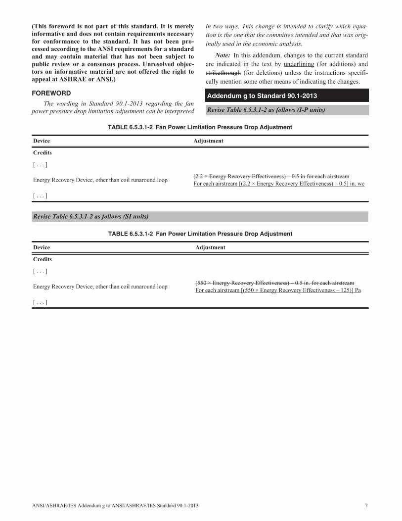
The wording in Standard 90.1-2013 regarding the fanpower pressure drop limitation adjustment can be interpreted
in two ways. This change is intended to clarify which equa-tion is the one that the committee intended and that was orig-inally used in the economic analysis.
Note: In this addendum, changes to the current standardare indicated in the text by underlining (for additions) andstrikethrough (for deletions) unless the instructions specifi-cally mention some other means of indicating the changes.
Addendum g to Standard 90.1-2013
Revise Table 6.5.3.1-2 as follows (I-P units)
TABLE 6.5.3.1-2 Fan Power Limitation Pressure Drop Adjustment
Device Adjustment
Credits
[ . . . ]
Energy Recovery Device, other than coil runaround loop(2.2 × Energy Recovery Effectiveness) – 0.5 in for each airstreamFor each airstream [(2.2 × Energy Recovery Effectiveness) – 0.5] in. wc
[ . . . ]
Revise Table 6.5.3.1-2 as follows (SI units)
TABLE 6.5.3.1-2 Fan Power Limitation Pressure Drop Adjustment
Device Adjustment
Credits
[ . . . ]
Energy Recovery Device, other than coil runaround loop(550 × Energy Recovery Effectiveness) – 0.5 in. for each airstreamFor each airstream [(550 × Energy Recovery Effectiveness – 125)] Pa
[ . . . ]
8 ANSI/ASHRAE/IES Addendum h to ANSI/ASHRAE/IES Standard 90.1-2013
(This foreword is not part of this standard. It is merelyinformative and does not contain requirements necessaryfor conformance to the standard. It has not been pro-cessed according to the ANSI requirements for a standardand may contain material that has not been subject topublic review or a consensus process. Unresolved objec-tors on informative material are not offered the right toappeal at ASHRAE or ANSI.)
FOREWORD
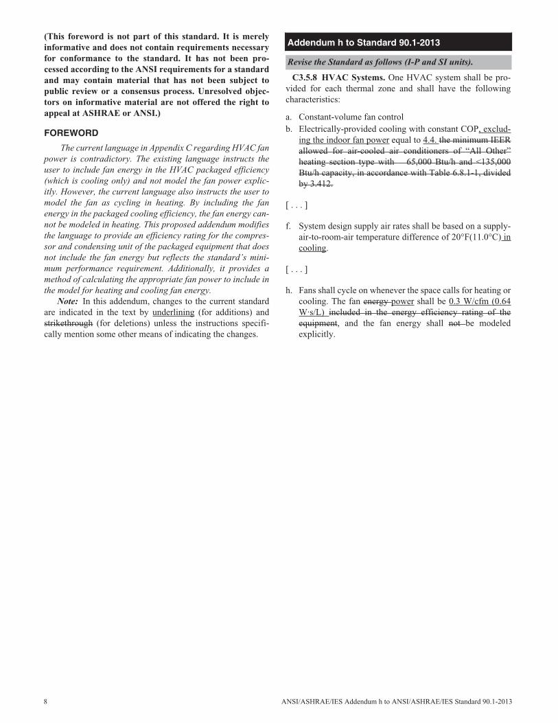
The current language in Appendix C regarding HVAC fanpower is contradictory. The existing language instructs theuser to include fan energy in the HVAC packaged efficiency(which is cooling only) and not model the fan power explic-itly. However, the current language also instructs the user tomodel the fan as cycling in heating. By including the fanenergy in the packaged cooling efficiency, the fan energy can-not be modeled in heating. This proposed addendum modifiesthe language to provide an efficiency rating for the compres-sor and condensing unit of the packaged equipment that doesnot include the fan energy but reflects the standard’s mini-mum performance requirement. Additionally, it provides amethod of calculating the appropriate fan power to include inthe model for heating and cooling fan energy.
Note: In this addendum, changes to the current standardare indicated in the text by underlining (for additions) andstrikethrough (for deletions) unless the instructions specifi-cally mention some other means of indicating the changes.
C3.5.8 HVAC Systems. One HVAC system shall be pro-vided for each thermal zone and shall have the followingcharacteristics:
a. Constant-volume fan controlb. Electrically-provided cooling with constant COP, exclud-
ing the indoor fan power equal to 4.4. the minimum IEERallowed for air-cooled air conditioners of “All Other”heating section type with 65,000 Btu/h and <135,000Btu/h capacity, in accordance with Table 6.8.1-1, dividedby 3.412.
[ . . . ]
f. System design supply air rates shall be based on a supply-air-to-room-air temperature difference of 20°F(11.0°C) incooling.
[ . . . ]
h. Fans shall cycle on whenever the space calls for heating orcooling. The fan energy power shall be 0.3 W/cfm (0.64W·s/L) included in the energy efficiency rating of theequipment, and the fan energy shall not be modeledexplicitly.
Addendum h to Standard 90.1-2013
Revise the Standard as follows (I-P and SI units).
ANSI/ASHRAE/IES Addendum j to ANSI/ASHRAE/IES Standard 90.1-2013 9
(This foreword is not part of this standard. It is merelyinformative and does not contain requirements necessaryfor conformance to the standard. It has not been pro-cessed according to the ANSI requirements for a standardand may contain material that has not been subject topublic review or a consensus process. Unresolved objec-tors on informative material are not offered the right toappeal at ASHRAE or ANSI.)
FOREWORD
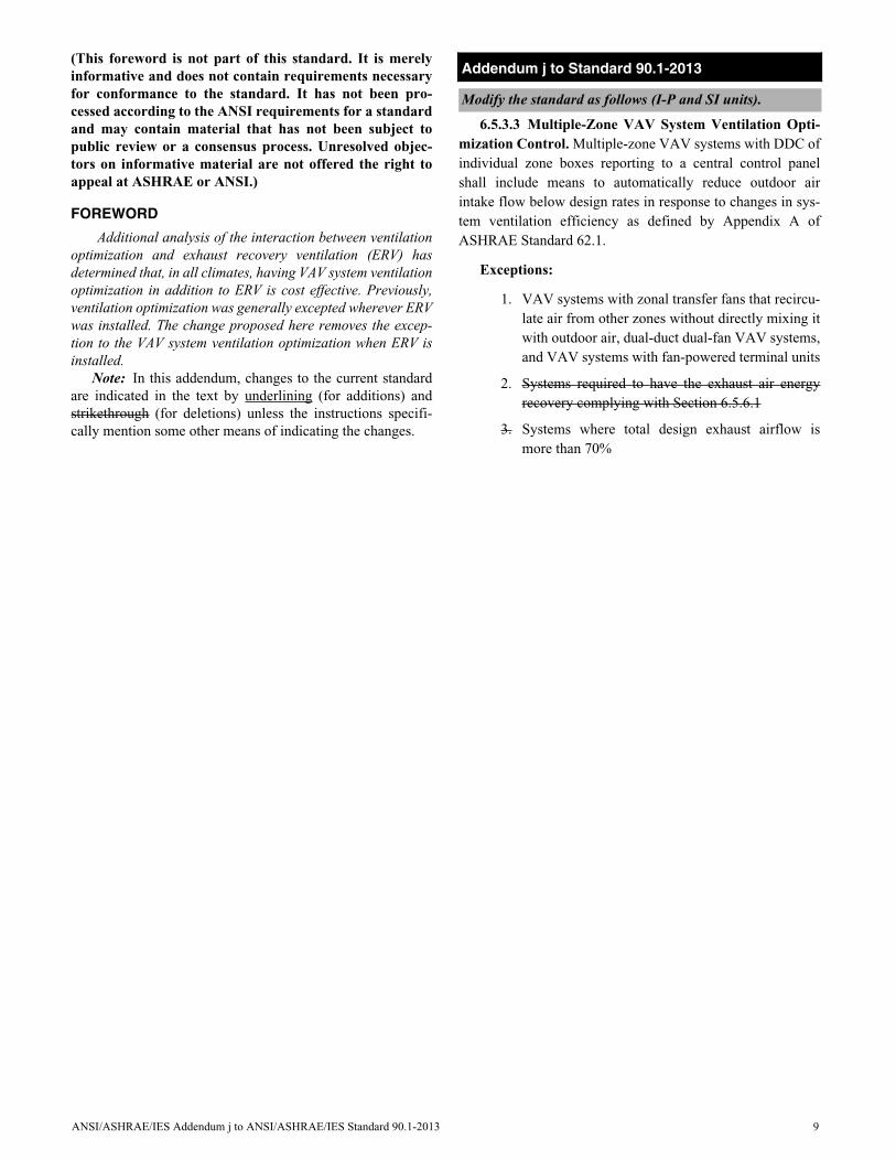
Additional analysis of the interaction between ventilationoptimization and exhaust recovery ventilation (ERV) hasdetermined that, in all climates, having VAV system ventilationoptimization in addition to ERV is cost effective. Previously,ventilation optimization was generally excepted wherever ERVwas installed. The change proposed here removes the excep-tion to the VAV system ventilation optimization when ERV isinstalled.
Note: In this addendum, changes to the current standardare indicated in the text by underlining (for additions) andstrikethrough (for deletions) unless the instructions specifi-cally mention some other means of indicating the changes.
6.5.3.3 Multiple-Zone VAV System Ventilation Opti-mization Control. Multiple-zone VAV systems with DDC ofindividual zone boxes reporting to a central control panelshall include means to automatically reduce outdoor airintake flow below design rates in response to changes in sys-tem ventilation efficiency as defined by Appendix A ofASHRAE Standard 62.1.
Exceptions:
1. VAV systems with zonal transfer fans that recircu-late air from other zones without directly mixing itwith outdoor air, dual-duct dual-fan VAV systems,and VAV systems with fan-powered terminal units
2. Systems required to have the exhaust air energyrecovery complying with Section 6.5.6.1
3. Systems where total design exhaust airflow ismore than 70%
Addendum j to Standard 90.1-2013
Modify the standard as follows (I-P and SI units).
10 ANSI/ASHRAE/IES Addendum k to ANSI/ASHRAE/IES Standard 90.1-2013
(This foreword is not part of this standard. It is merelyinformative and does not contain requirements necessaryfor conformance to the standard. It has not been pro-cessed according to the ANSI requirements for a standardand may contain material that has not been subject topublic review or a consensus process. Unresolved objec-tors on informative material are not offered the right toappeal at ASHRAE or ANSI.)
FOREWORD
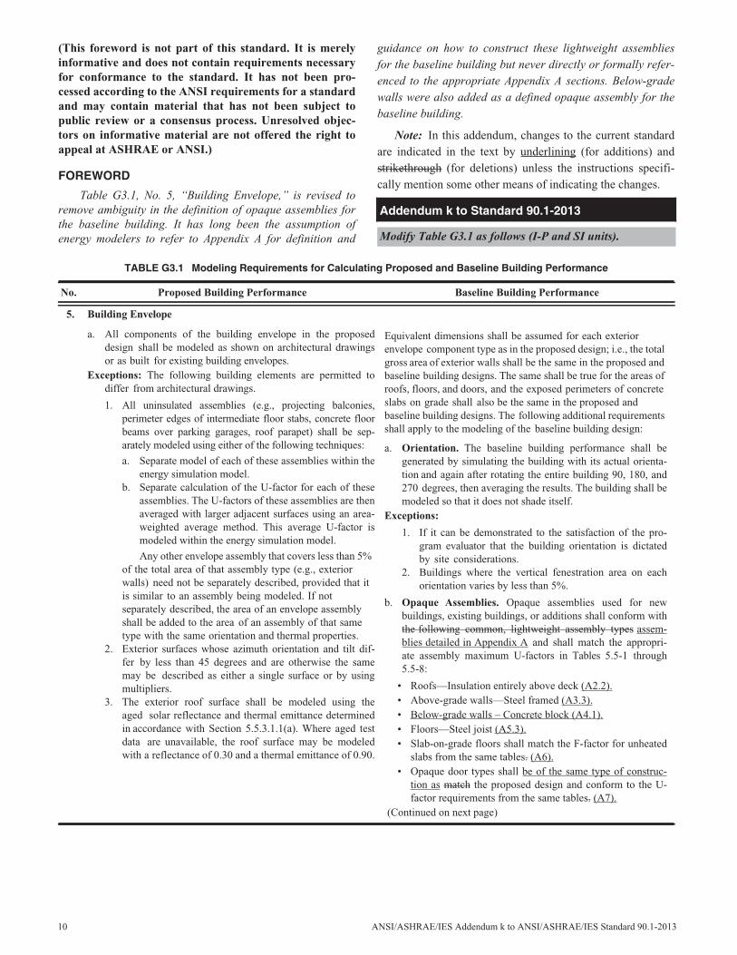
Table G3.1, No. 5, “Building Envelope,” is revised toremove ambiguity in the definition of opaque assemblies forthe baseline building. It has long been the assumption ofenergy modelers to refer to Appendix A for definition and
guidance on how to construct these lightweight assembliesfor the baseline building but never directly or formally refer-enced to the appropriate Appendix A sections. Below-gradewalls were also added as a defined opaque assembly for thebaseline building.
Note: In this addendum, changes to the current standardare indicated in the text by underlining (for additions) andstrikethrough (for deletions) unless the instructions specifi-cally mention some other means of indicating the changes.
Addendum k to Standard 90.1-2013
Modify Table G3.1 as follows (I-P and SI units).
TABLE G3.1 Modeling Requirements for Calculating Proposed and Baseline Building Performance
No. Proposed Building Performance Baseline Building Performance
5. Building Envelope
a. All components of the building envelope in the proposeddesign shall be modeled as shown on architectural drawingsor as built for existing building envelopes.
Exceptions: The following building elements are permitted todiffer from architectural drawings.
1. All uninsulated assemblies (e.g., projecting balconies,perimeter edges of intermediate floor stabs, concrete floorbeams over parking garages, roof parapet) shall be sep-arately modeled using either of the following techniques:
a. Separate model of each of these assemblies within theenergy simulation model.
b. Separate calculation of the U-factor for each of theseassemblies. The U-factors of these assemblies are thenaveraged with larger adjacent surfaces using an area-weighted average method. This average U-factor ismodeled within the energy simulation model.
Any other envelope assembly that covers less than 5%of the total area of that assembly type (e.g., exteriorwalls) need not be separately described, provided that itis similar to an assembly being modeled. If notseparately described, the area of an envelope assemblyshall be added to the area of an assembly of that sametype with the same orientation and thermal properties.
2. Exterior surfaces whose azimuth orientation and tilt dif-fer by less than 45 degrees and are otherwise the samemay be described as either a single surface or by usingmultipliers.
3. The exterior roof surface shall be modeled using theaged solar reflectance and thermal emittance determinedin accordance with Section 5.5.3.1.1(a). Where aged testdata are unavailable, the roof surface may be modeledwith a reflectance of 0.30 and a thermal emittance of 0.90.
Equivalent dimensions shall be assumed for each exteriorenvelope component type as in the proposed design; i.e., the totalgross area of exterior walls shall be the same in the proposed andbaseline building designs. The same shall be true for the areas ofroofs, floors, and doors, and the exposed perimeters of concreteslabs on grade shall also be the same in the proposed andbaseline building designs. The following additional requirementsshall apply to the modeling of the baseline building design:
a. Orientation. The baseline building performance shall begenerated by simulating the building with its actual orienta-tion and again after rotating the entire building 90, 180, and270 degrees, then averaging the results. The building shall bemodeled so that it does not shade itself.
Exceptions:
1. If it can be demonstrated to the satisfaction of the pro-gram evaluator that the building orientation is dictatedby site considerations.
2. Buildings where the vertical fenestration area on eachorientation varies by less than 5%.
b. Opaque Assemblies. Opaque assemblies used for newbuildings, existing buildings, or additions shall conform withthe following common, lightweight assembly types assem-blies detailed in Appendix A and shall match the appropri-ate assembly maximum U-factors in Tables 5.5-1 through5.5-8:
• Roofs—Insulation entirely above deck (A2.2).• Above-grade walls—Steel framed (A3.3).• Below-grade walls – Concrete block (A4.1).• Floors—Steel joist (A5.3).• Slab-on-grade floors shall match the F-factor for unheated
slabs from the same tables. (A6).• Opaque door types shall be of the same type of construc-
tion as match the proposed design and conform to the U-factor requirements from the same tables. (A7).
(Continued on next page)
ANSI/ASHRAE/IES Addendum m to ANSI/ASHRAE/IES Standard 90.1-2013 11
(This foreword is not part of this standard. It is merelyinformative and does not contain requirements necessaryfor conformance to the standard. It has not been pro-cessed according to the ANSI requirements for a standardand may contain material that has not been subject topublic review or a consensus process. Unresolved objec-tors on informative material are not offered the right toappeal at ASHRAE or ANSI.)
FOREWORD
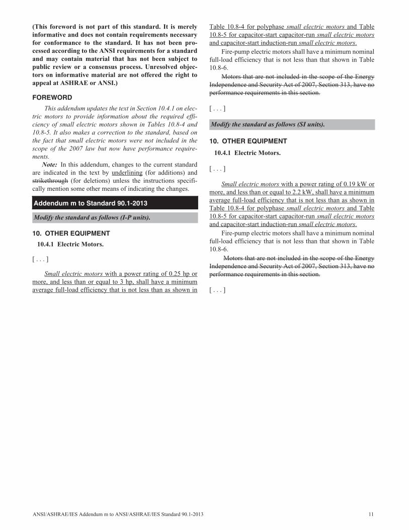
This addendum updates the text in Section 10.4.1 on elec-tric motors to provide information about the required effi-ciency of small electric motors shown in Tables 10.8-4 and10.8-5. It also makes a correction to the standard, based onthe fact that small electric motors were not included in thescope of the 2007 law but now have performance require-ments.
Note: In this addendum, changes to the current standardare indicated in the text by underlining (for additions) andstrikethrough (for deletions) unless the instructions specifi-cally mention some other means of indicating the changes.
10. OTHER EQUIPMENT
10.4.1 Electric Motors.
[ . . . ]
Small electric motors with a power rating of 0.25 hp ormore, and less than or equal to 3 hp, shall have a minimumaverage full-load efficiency that is not less than as shown in
Table 10.8-4 for polyphase small electric motors and Table10.8-5 for capacitor-start capacitor-run small electric motorsand capacitor-start induction-run small electric motors.
Fire-pump electric motors shall have a minimum nominalfull-load efficiency that is not less than that shown in Table10.8-6.
Motors that are not included in the scope of the EnergyIndependence and Security Act of 2007, Section 313, have noperformance requirements in this section.
[ . . . ]
10. OTHER EQUIPMENT
10.4.1 Electric Motors.
[ . . . ]
Small electric motors with a power rating of 0.19 kW ormore, and less than or equal to 2.2 kW, shall have a minimumaverage full-load efficiency that is not less than as shown inTable 10.8-4 for polyphase small electric motors and Table10.8-5 for capacitor-start capacitor-run small electric motorsand capacitor-start induction-run small electric motors.
Fire-pump electric motors shall have a minimum nominalfull-load efficiency that is not less than that shown in Table10.8-6.
Motors that are not included in the scope of the EnergyIndependence and Security Act of 2007, Section 313, have noperformance requirements in this section.
[ . . . ]
Addendum m to Standard 90.1-2013
Modify the standard as follows (I-P units).
Modify the standard as follows (SI units).
(This foreword is not part of this standard. It is merelyinformative and does not contain requirements necessaryfor conformance to the standard. It has not been pro-cessed according to the ANSI requirements for a standardand may contain material that has not been subject topublic review or a consensus process. Unresolved objec-tors on informative material are not offered the right toappeal at ASHRAE or ANSI.)
FOREWORD
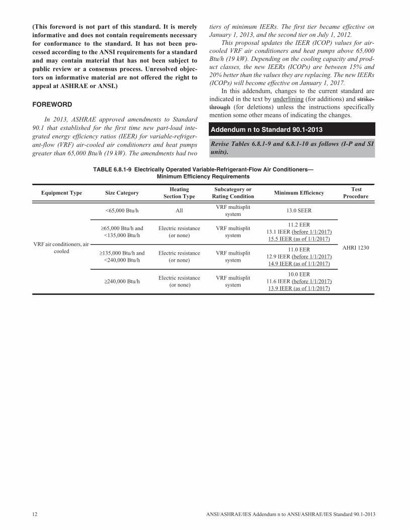
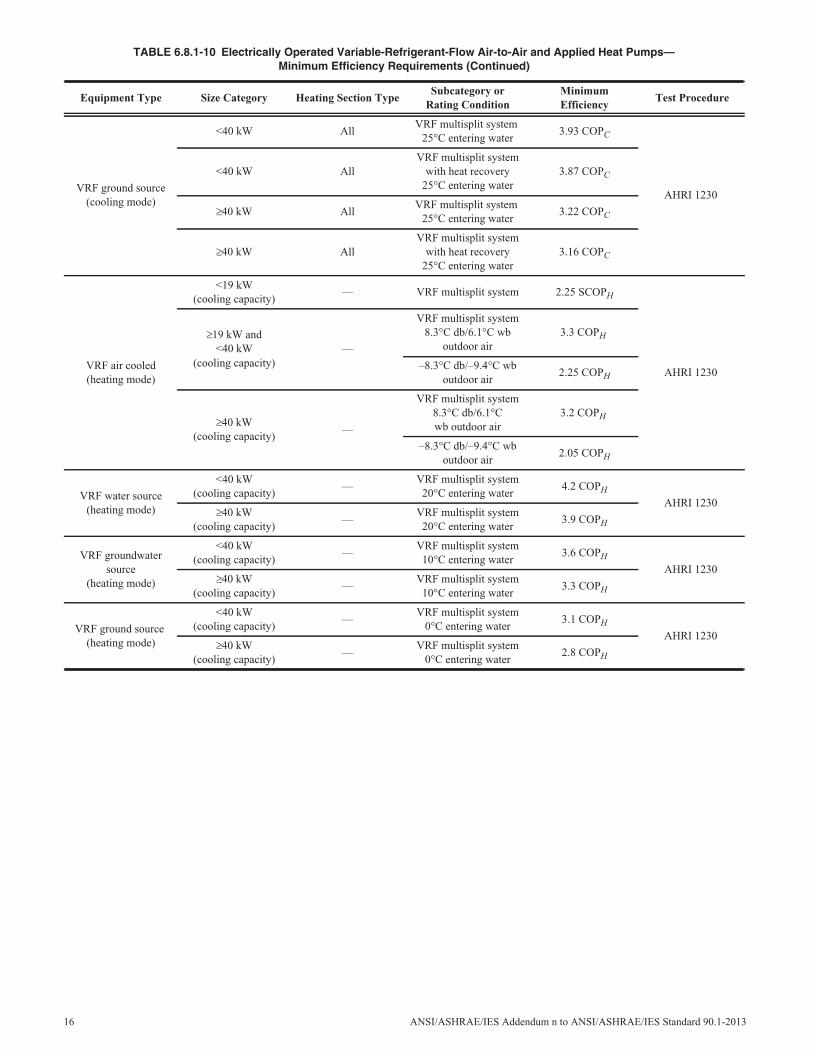
In 2013, ASHRAE approved amendments to Standard90.1 that established for the first time new part-load inte-grated energy efficiency ratios (IEER) for variable-refriger-ant-flow (VRF) air-cooled air conditioners and heat pumpsgreater than 65,000 Btu/h (19 kW). The amendments had two
tiers of minimum IEERs. The first tier became effective onJanuary 1, 2013, and the second tier on July 1, 2012.
This proposal updates the IEER (ICOP) values for air-cooled VRF air conditioners and heat pumps above 65,000Btu/h (19 kW). Depending on the cooling capacity and prod-uct classes, the new IEERs (ICOPs) are between 15% and20% better than the values they are replacing. The new IEERs(ICOPs) will become effective on January 1, 2017.
In this addendum, changes to the current standard areindicated in the text by underlining (for additions) and strike-through (for deletions) unless the instructions specificallymention some other means of indicating the changes.
Addendum n to Standard 90.1-2013
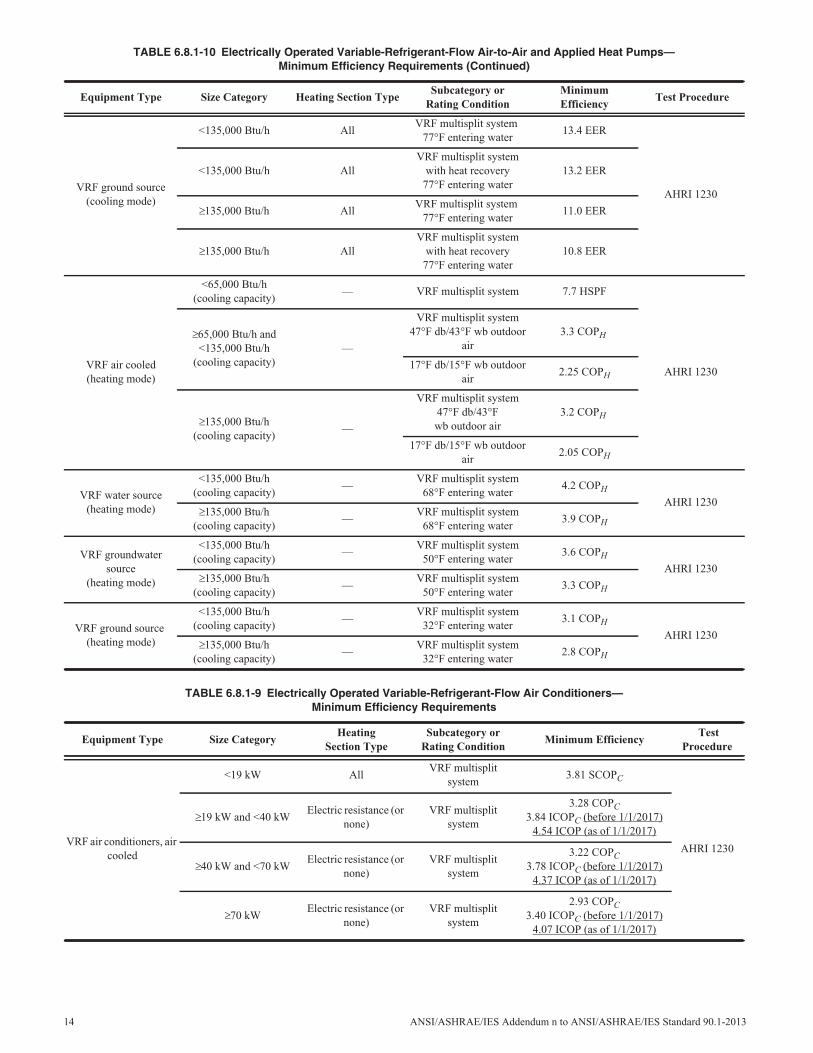
Revise Tables 6.8.1-9 and 6.8.1-10 as follows (I-P and SIunits).
TABLE 6.8.1-9 Electrically Operated Variable-Refrigerant-Flow Air Conditioners—Minimum Efficiency Requirements
Equipment Type Size CategoryHeating
Section TypeSubcategory or
Rating ConditionMinimum Efficiency
TestProcedure
VRF air conditioners, aircooled
<65,000 Btu/h AllVRF multisplit
system13.0 SEER
AHRI 1230
65,000 Btu/h and<135,000 Btu/h
Electric resistance(or none)
VRF multisplitsystem
11.2 EER13.1 IEER (before 1/1/2017)15.5 IEER (as of 1/1/2017)
135,000 Btu/h and<240,000 Btu/h
Electric resistance(or none)
VRF multisplitsystem
11.0 EER12.9 IEER (before 1/1/2017)14.9 IEER (as of 1/1/2017)
240,000 Btu/hElectric resistance
(or none)VRF multisplit
system
10.0 EER11.6 IEER (before 1/1/2017)13.9 IEER (as of 1/1/2017)
12 ANSI/ASHRAE/IES Addendum n to ANSI/ASHRAE/IES Standard 90.1-2013
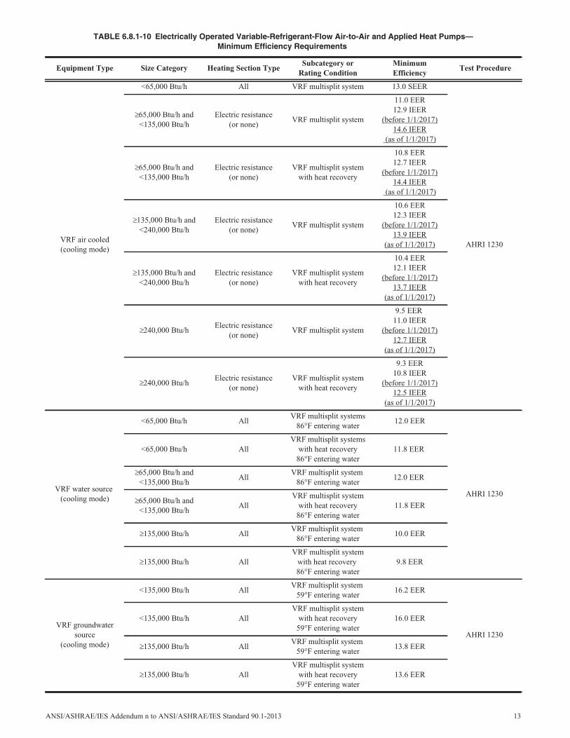
TABLE 6.8.1-10 Electrically Operated Variable-Refrigerant-Flow Air-to-Air and Applied Heat Pumps—Minimum Efficiency Requirements
Equipment Type Size Category Heating Section TypeSubcategory or
Rating ConditionMinimumEfficiency
Test Procedure
VRF air cooled(cooling mode)
<65,000 Btu/h All VRF multisplit system 13.0 SEER
AHRI 1230
65,000 Btu/h and<135,000 Btu/h
Electric resistance(or none)
VRF multisplit system
11.0 EER12.9 IEER
(before 1/1/2017)14.6 IEER
(as of 1/1/2017)
65,000 Btu/h and<135,000 Btu/h
Electric resistance(or none)
VRF multisplit systemwith heat recovery
10.8 EER12.7 IEER
(before 1/1/2017)14.4 IEER
(as of 1/1/2017)
135,000 Btu/h and<240,000 Btu/h
Electric resistance(or none)
VRF multisplit system
10.6 EER12.3 IEER
(before 1/1/2017)13.9 IEER
(as of 1/1/2017)
135,000 Btu/h and<240,000 Btu/h
Electric resistance(or none)
VRF multisplit systemwith heat recovery
10.4 EER12.1 IEER
(before 1/1/2017)13.7 IEER
(as of 1/1/2017)
240,000 Btu/hElectric resistance
(or none)VRF multisplit system
9.5 EER11.0 IEER
(before 1/1/2017)12.7 IEER
(as of 1/1/2017)
240,000 Btu/hElectric resistance
(or none)VRF multisplit system
with heat recovery
9.3 EER10.8 IEER
(before 1/1/2017)12.5 IEER
(as of 1/1/2017)
VRF water source(cooling mode)
<65,000 Btu/h AllVRF multisplit systems
86°F entering water12.0 EER
AHRI 1230
<65,000 Btu/h AllVRF multisplit systems
with heat recovery86°F entering water
11.8 EER
65,000 Btu/h and<135,000 Btu/h
AllVRF multisplit system
86°F entering water12.0 EER
65,000 Btu/h and<135,000 Btu/h
AllVRF multisplit system
with heat recovery86°F entering water
11.8 EER
135,000 Btu/h AllVRF multisplit system
86°F entering water10.0 EER
135,000 Btu/h AllVRF multisplit system
with heat recovery86°F entering water
9.8 EER
VRF groundwatersource
(cooling mode)
<135,000 Btu/h AllVRF multisplit system
59°F entering water16.2 EER
AHRI 1230
<135,000 Btu/h AllVRF multisplit system
with heat recovery59°F entering water
16.0 EER
135,000 Btu/h AllVRF multisplit system
59°F entering water13.8 EER
135,000 Btu/h AllVRF multisplit system
with heat recovery59°F entering water
13.6 EER
ANSI/ASHRAE/IES Addendum n to ANSI/ASHRAE/IES Standard 90.1-2013 13
VRF ground source(cooling mode)
<135,000 Btu/h AllVRF multisplit system
77°F entering water13.4 EER
AHRI 1230
<135,000 Btu/h AllVRF multisplit system
with heat recovery77°F entering water
13.2 EER
135,000 Btu/h AllVRF multisplit system
77°F entering water11.0 EER
135,000 Btu/h AllVRF multisplit system
with heat recovery77°F entering water
10.8 EER
VRF air cooled(heating mode)
<65,000 Btu/h(cooling capacity)
— VRF multisplit system 7.7 HSPF
AHRI 1230
65,000 Btu/h and<135,000 Btu/h
(cooling capacity)—
VRF multisplit system47°F db/43°F wb outdoor
air3.3 COPH
17°F db/15°F wb outdoorair
2.25 COPH
135,000 Btu/h(cooling capacity)
—
VRF multisplit system47°F db/43°Fwb outdoor air
3.2 COPH
17°F db/15°F wb outdoorair
2.05 COPH
VRF water source(heating mode)
<135,000 Btu/h(cooling capacity)
—VRF multisplit system
68°F entering water4.2 COPH
AHRI 1230135,000 Btu/h
(cooling capacity)—
VRF multisplit system68°F entering water
3.9 COPH
VRF groundwatersource
(heating mode)
<135,000 Btu/h(cooling capacity)
—VRF multisplit system
50°F entering water3.6 COPH
AHRI 1230135,000 Btu/h
(cooling capacity)—
VRF multisplit system50°F entering water
3.3 COPH
VRF ground source(heating mode)
<135,000 Btu/h(cooling capacity)
—VRF multisplit system
32°F entering water3.1 COPH
AHRI 1230135,000 Btu/h
(cooling capacity)—
VRF multisplit system32°F entering water
2.8 COPH
TABLE 6.8.1-9 Electrically Operated Variable-Refrigerant-Flow Air Conditioners—Minimum Efficiency Requirements
Equipment Type Size CategoryHeating
Section TypeSubcategory or
Rating ConditionMinimum Efficiency
TestProcedure
VRF air conditioners, aircooled
<19 kW AllVRF multisplit
system3.81 SCOPC
AHRI 1230
19 kW and <40 kWElectric resistance (or
none)VRF multisplit
system
3.28 COPC3.84 ICOPC (before 1/1/2017)
4.54 ICOP (as of 1/1/2017)
40 kW and <70 kWElectric resistance (or
none)VRF multisplit
system
3.22 COPC3.78 ICOPC (before 1/1/2017)
4.37 ICOP (as of 1/1/2017)
70 kWElectric resistance (or
none)VRF multisplit
system
2.93 COPC3.40 ICOPC (before 1/1/2017)
4.07 ICOP (as of 1/1/2017)
TABLE 6.8.1-10 Electrically Operated Variable-Refrigerant-Flow Air-to-Air and Applied Heat Pumps—Minimum Efficiency Requirements (Continued)
Equipment Type Size Category Heating Section TypeSubcategory or
Rating ConditionMinimumEfficiency
Test Procedure
14 ANSI/ASHRAE/IES Addendum n to ANSI/ASHRAE/IES Standard 90.1-2013
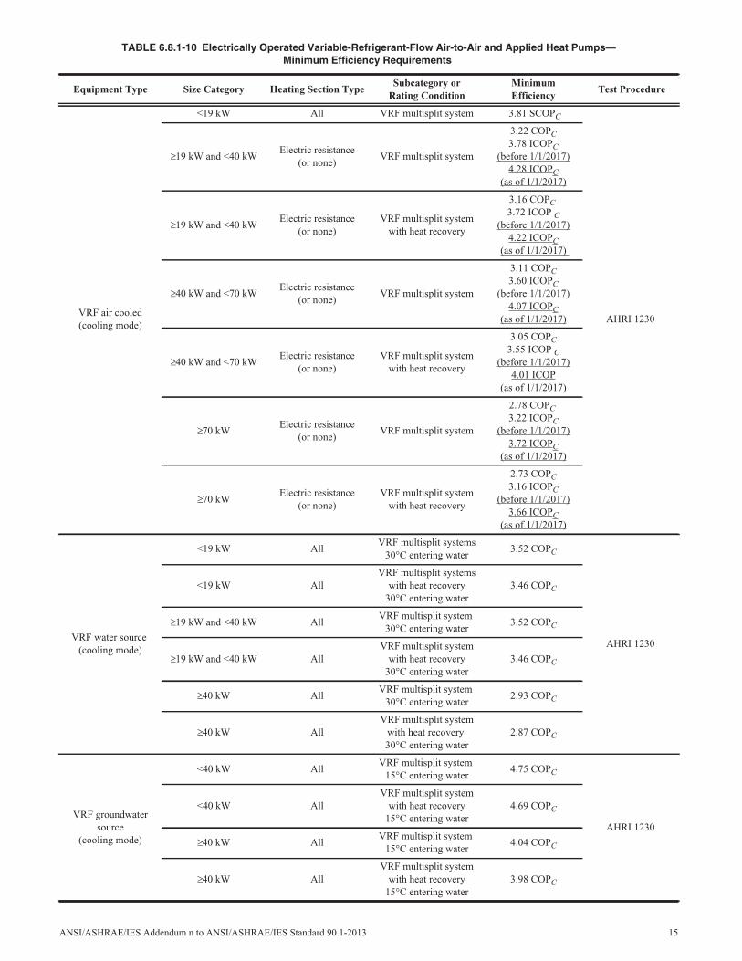
TABLE 6.8.1-10 Electrically Operated Variable-Refrigerant-Flow Air-to-Air and Applied Heat Pumps—Minimum Efficiency Requirements
Equipment Type Size Category Heating Section TypeSubcategory or
Rating ConditionMinimumEfficiency
Test Procedure
VRF air cooled(cooling mode)
<19 kW All VRF multisplit system 3.81 SCOPC
AHRI 1230
19 kW and <40 kWElectric resistance
(or none)VRF multisplit system
3.22 COPC3.78 ICOPC
(before 1/1/2017)4.28 ICOPC
(as of 1/1/2017)
19 kW and <40 kWElectric resistance
(or none)VRF multisplit system
with heat recovery
3.16 COPC3.72 ICOP C
(before 1/1/2017)4.22 ICOPC
(as of 1/1/2017)
40 kW and <70 kWElectric resistance
(or none)VRF multisplit system
3.11 COPC3.60 ICOPC
(before 1/1/2017)4.07 ICOPC
(as of 1/1/2017)
40 kW and <70 kWElectric resistance
(or none)VRF multisplit system
with heat recovery
3.05 COPC3.55 ICOP C
(before 1/1/2017)4.01 ICOP
(as of 1/1/2017)
70 kWElectric resistance
(or none)VRF multisplit system
2.78 COPC3.22 ICOPC
(before 1/1/2017)3.72 ICOPC
(as of 1/1/2017)
70 kWElectric resistance
(or none)VRF multisplit system
with heat recovery
2.73 COPC3.16 ICOPC
(before 1/1/2017)3.66 ICOPC
(as of 1/1/2017)
VRF water source(cooling mode)
<19 kW AllVRF multisplit systems
30°C entering water3.52 COPC
AHRI 1230
<19 kW AllVRF multisplit systems
with heat recovery30°C entering water
3.46 COPC
19 kW and <40 kW AllVRF multisplit system
30°C entering water3.52 COPC
19 kW and <40 kW AllVRF multisplit system
with heat recovery30°C entering water
3.46 COPC
40 kW AllVRF multisplit system
30°C entering water2.93 COPC
40 kW AllVRF multisplit system
with heat recovery30°C entering water
2.87 COPC
VRF groundwatersource
(cooling mode)
<40 kW AllVRF multisplit system
15°C entering water4.75 COPC
AHRI 1230
<40 kW AllVRF multisplit system
with heat recovery15°C entering water
4.69 COPC
40 kW AllVRF multisplit system
15°C entering water4.04 COPC
40 kW AllVRF multisplit system
with heat recovery15°C entering water
3.98 COPC
ANSI/ASHRAE/IES Addendum n to ANSI/ASHRAE/IES Standard 90.1-2013 15
VRF ground source(cooling mode)
<40 kW AllVRF multisplit system
25°C entering water3.93 COPC
AHRI 1230
<40 kW AllVRF multisplit system
with heat recovery25°C entering water
3.87 COPC
40 kW AllVRF multisplit system
25°C entering water3.22 COPC
40 kW AllVRF multisplit system
with heat recovery25°C entering water
3.16 COPC
VRF air cooled(heating mode)
<19 kW(cooling capacity)
— VRF multisplit system 2.25 SCOPH
AHRI 1230
19 kW and<40 kW
(cooling capacity)—
VRF multisplit system8.3°C db/6.1°C wb
outdoor air3.3 COPH
–8.3°C db/–9.4°C wboutdoor air
2.25 COPH
40 kW(cooling capacity)
—
VRF multisplit system8.3°C db/6.1°Cwb outdoor air
3.2 COPH
–8.3°C db/–9.4°C wboutdoor air
2.05 COPH
VRF water source(heating mode)
<40 kW(cooling capacity)
—VRF multisplit system20°C entering water
4.2 COPH
AHRI 123040 kW
(cooling capacity)—
VRF multisplit system20°C entering water
3.9 COPH
VRF groundwatersource
(heating mode)
<40 kW(cooling capacity)
—VRF multisplit system10°C entering water
3.6 COPH
AHRI 123040 kW
(cooling capacity)—
VRF multisplit system10°C entering water
3.3 COPH
VRF ground source(heating mode)
<40 kW(cooling capacity)
—VRF multisplit system
0°C entering water3.1 COPH
AHRI 123040 kW
(cooling capacity)—
VRF multisplit system0°C entering water
2.8 COPH
TABLE 6.8.1-10 Electrically Operated Variable-Refrigerant-Flow Air-to-Air and Applied Heat Pumps—Minimum Efficiency Requirements (Continued)
Equipment Type Size Category Heating Section TypeSubcategory or
Rating ConditionMinimumEfficiency
Test Procedure
16 ANSI/ASHRAE/IES Addendum n to ANSI/ASHRAE/IES Standard 90.1-2013
ANSI/ASHRAE/IES Addendum o to ANSI/ASHRAE/IES Standard 90.1-2013 17
(This foreword is not part of this standard. It is merelyinformative and does not contain requirements necessaryfor conformance to the standard. It has not been pro-cessed according to the ANSI requirements for a standardand may contain material that has not been subject topublic review or a consensus process. Unresolved objec-tors on informative material are not offered the right toappeal at ASHRAE or ANSI.)
FOREWORD
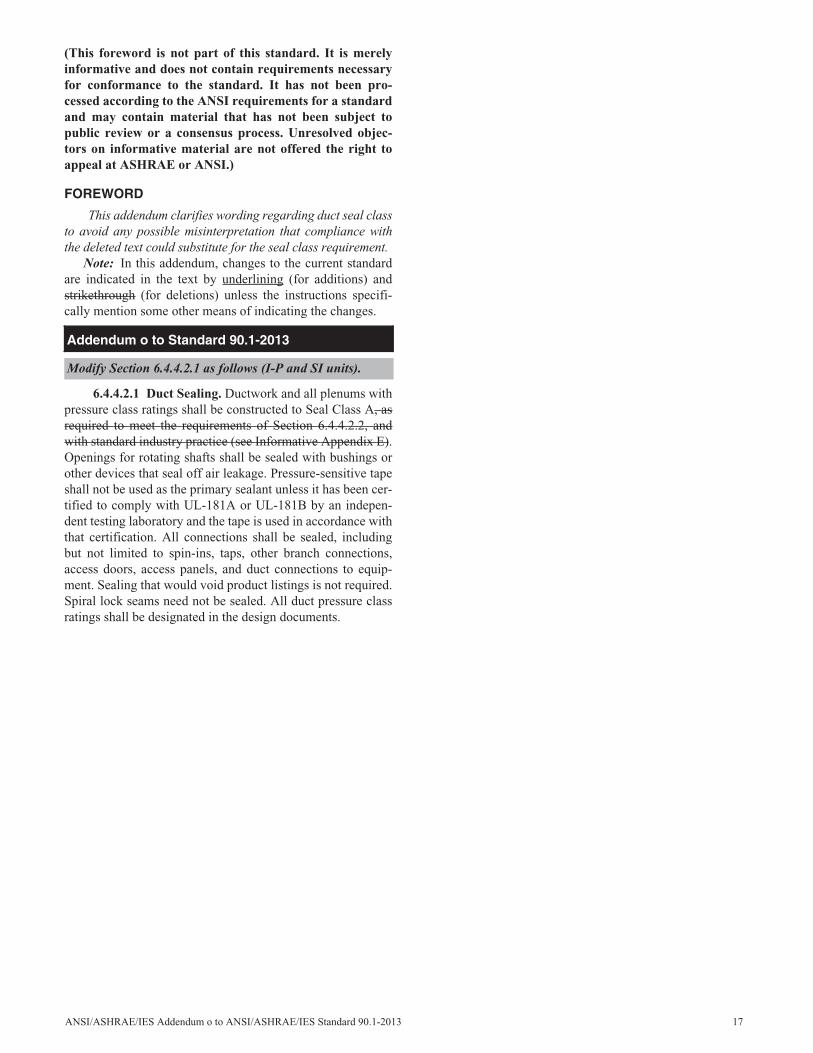
This addendum clarifies wording regarding duct seal classto avoid any possible misinterpretation that compliance withthe deleted text could substitute for the seal class requirement.
Note: In this addendum, changes to the current standardare indicated in the text by underlining (for additions) andstrikethrough (for deletions) unless the instructions specifi-cally mention some other means of indicating the changes.
6.4.4.2.1 Duct Sealing. Ductwork and all plenums withpressure class ratings shall be constructed to Seal Class A, asrequired to meet the requirements of Section 6.4.4.2.2, andwith standard industry practice (see Informative Appendix E).Openings for rotating shafts shall be sealed with bushings orother devices that seal off air leakage. Pressure-sensitive tapeshall not be used as the primary sealant unless it has been cer-tified to comply with UL-181A or UL-181B by an indepen-dent testing laboratory and the tape is used in accordance withthat certification. All connections shall be sealed, includingbut not limited to spin-ins, taps, other branch connections,access doors, access panels, and duct connections to equip-ment. Sealing that would void product listings is not required.Spiral lock seams need not be sealed. All duct pressure classratings shall be designated in the design documents.
Addendum o to Standard 90.1-2013
Modify Section 6.4.4.2.1 as follows (I-P and SI units).
(This foreword is not part of this standard. It is merelyinformative and does not contain requirements necessaryfor conformance to the standard. It has not been pro-cessed according to the ANSI requirements for a standardand may contain material that has not been subject topublic review or a consensus process. Unresolved objec-tors on informative material are not offered the right toappeal at ASHRAE or ANSI.)
FOREWORD
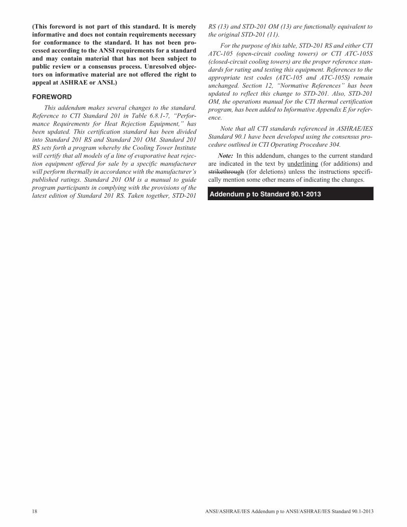
This addendum makes several changes to the standard.Reference to CTI Standard 201 in Table 6.8.1-7, “Perfor-mance Requirements for Heat Rejection Equipment,” hasbeen updated. This certification standard has been dividedinto Standard 201 RS and Standard 201 OM. Standard 201RS sets forth a program whereby the Cooling Tower Institutewill certify that all models of a line of evaporative heat rejec-tion equipment offered for sale by a specific manufacturerwill perform thermally in accordance with the manufacturer’spublished ratings. Standard 201 OM is a manual to guideprogram participants in complying with the provisions of thelatest edition of Standard 201 RS. Taken together, STD-201
RS (13) and STD-201 OM (13) are functionally equivalent tothe original STD-201 (11).
For the purpose of this table, STD-201 RS and either CTIATC-105 (open-circuit cooling towers) or CTI ATC-105S(closed-circuit cooling towers) are the proper reference stan-dards for rating and testing this equipment. References to theappropriate test codes (ATC-105 and ATC-105S) remainunchanged. Section 12, “Normative References” has beenupdated to reflect this change to STD-201. Also, STD-201OM, the operations manual for the CTI thermal certificationprogram, has been added to Informative Appendix E for refer-ence.
Note that all CTI standards referenced in ASHRAE/IESStandard 90.1 have been developed using the consensus pro-cedure outlined in CTI Operating Procedure 304.
Note: In this addendum, changes to the current standardare indicated in the text by underlining (for additions) andstrikethrough (for deletions) unless the instructions specifi-cally mention some other means of indicating the changes.
Addendum p to Standard 90.1-2013
18 ANSI/ASHRAE/IES Addendum p to ANSI/ASHRAE/IES Standard 90.1-2013
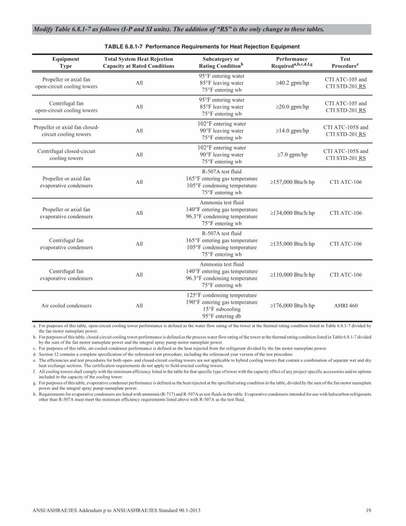
Modify Table 6.8.1-7 as follows (I-P and SI units). The addition of “RS” is the only change to these tables.
TABLE 6.8.1-7 Performance Requirements for Heat Rejection Equipment
EquipmentType
Total System Heat RejectionCapacity at Rated Conditions
Subcategory orRating Conditionh
PerformanceRequireda,b,c,d,f,g
TestProceduree
Propeller or axial fanopen-circuit cooling towers
All95°F entering water85°F leaving water75°F entering wb
40.2 gpm/hpCTI ATC-105 andCTI STD-201 RS
Centrifugal fanopen-circuit cooling towers
All95°F entering water85°F leaving water75°F entering wb
20.0 gpm/hpCTI ATC-105 andCTI STD-201 RS
Propeller or axial fan closed-circuit cooling towers
All102°F entering water90°F leaving water75°F entering wb
14.0 gpm/hpCTI ATC-105S andCTI STD-201 RS
Centrifugal closed-circuitcooling towers
All102°F entering water90°F leaving water75°F entering wb
7.0 gpm/hpCTI ATC-105S andCTI STD-201 RS
Propeller or axial fanevaporative condensers
All
R-507A test fluid165°F entering gas temperature105°F condensing temperature
75°F entering wb
157,000 Btu/h·hp CTI ATC-106
Propeller or axial fanevaporative condensers
All
Ammonia test fluid140°F entering gas temperature96.3°F condensing temperature
75°F entering wb
134,000 Btu/h·hp CTI ATC-106
Centrifugal fanevaporative condensers
All
R-507A test fluid165°F entering gas temperature105°F condensing temperature
75°F entering wb
135,000 Btu/h·hp CTI ATC-106
Centrifugal fanevaporative condensers
All
Ammonia test fluid140°F entering gas temperature96.3°F condensing temperature
75°F entering wb
110,000 Btu/h·hp CTI ATC-106
Air cooled condensers All
125°F condensing temperature190°F entering gas temperature
15°F subcooling95°F entering db
176,000 Btu/h·hp AHRI 460
a. For purposes of this table, open-circuit cooling tower performance is defined as the water flow rating of the tower at the thermal rating condition listed in Table 6.8.1-7 divided bythe fan motor nameplate power.
b. For purposes of this table, closed-circuit cooling tower performance is defined as the process water flow rating of the tower at the thermal rating condition listed in Table 6.8.1-7 dividedby the sum of the fan motor nameplate power and the integral spray pump motor nameplate power.
c. For purposes of this table, air-cooled condenser performance is defined as the heat rejected from the refrigerant divided by the fan motor nameplate power.d. Section 12 contains a complete specification of the referenced test procedure, including the referenced year version of the test procedure.e. The efficiencies and test procedures for both open- and closed-circuit cooling towers are not applicable to hybrid cooling towers that contain a combination of separate wet and dry
heat exchange sections. The certification requirements do not apply to field-erected cooling towers.f. All cooling towers shall comply with the minimum efficiency listed in the table for that specific type of tower with the capacity effect of any project-specific accessories and/or options
included in the capacity of the cooling tower.g. For purposes of this table, evaporative condenser performance is defined as the heat rejected at the specified rating condition in the table, divided by the sum of the fan motor nameplate
power and the integral spray pump nameplate power.h. Requirements for evaporative condensers are listed with ammonia (R-717) and R-507A as test fluids in the table. Evaporative condensers intended for use with halocarbon refrigerants
other than R-507A must meet the minimum efficiency requirements listed above with R-507A as the test fluid.
ANSI/ASHRAE/IES Addendum p to ANSI/ASHRAE/IES Standard 90.1-2013 19
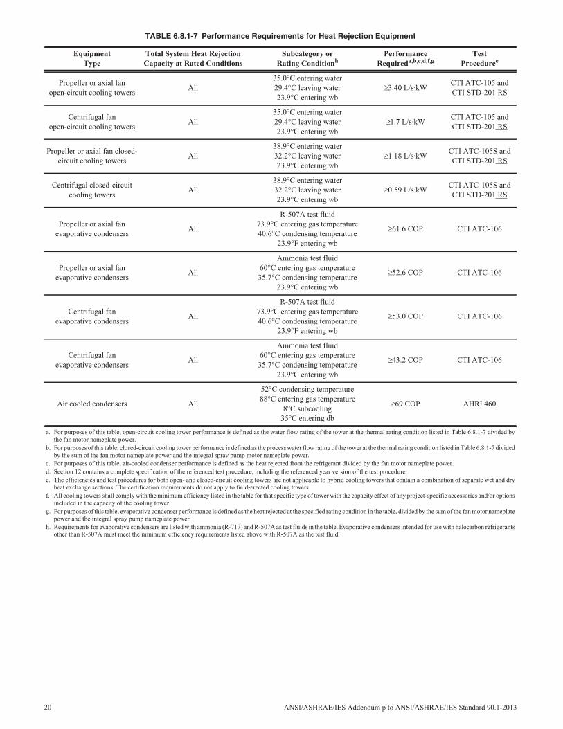
TABLE 6.8.1-7 Performance Requirements for Heat Rejection Equipment
EquipmentType
Total System Heat RejectionCapacity at Rated Conditions
Subcategory orRating Conditionh
PerformanceRequireda,b,c,d,f,g
TestProceduree
Propeller or axial fanopen-circuit cooling towers
All35.0°C entering water29.4°C leaving water23.9°C entering wb
3.40 L/s·kWCTI ATC-105 andCTI STD-201 RS
Centrifugal fanopen-circuit cooling towers
All35.0°C entering water29.4°C leaving water23.9°C entering wb
1.7 L/s·kWCTI ATC-105 andCTI STD-201 RS
Propeller or axial fan closed-circuit cooling towers
All38.9°C entering water32.2°C leaving water23.9°C entering wb
1.18 L/s·kWCTI ATC-105S andCTI STD-201 RS
Centrifugal closed-circuitcooling towers
All38.9°C entering water32.2°C leaving water23.9°C entering wb
0.59 L/s·kWCTI ATC-105S andCTI STD-201 RS
Propeller or axial fanevaporative condensers
All
R-507A test fluid73.9°C entering gas temperature40.6°C condensing temperature
23.9°F entering wb
61.6 COP CTI ATC-106
Propeller or axial fanevaporative condensers
All
Ammonia test fluid60°C entering gas temperature35.7°C condensing temperature
23.9°C entering wb
52.6 COP CTI ATC-106
Centrifugal fanevaporative condensers
All
R-507A test fluid73.9°C entering gas temperature40.6°C condensing temperature
23.9°F entering wb
53.0 COP CTI ATC-106
Centrifugal fanevaporative condensers
All
Ammonia test fluid60°C entering gas temperature35.7°C condensing temperature
23.9°C entering wb
43.2 COP CTI ATC-106
Air cooled condensers All
52°C condensing temperature88°C entering gas temperature
8°C subcooling35°C entering db
69 COP AHRI 460
a. For purposes of this table, open-circuit cooling tower performance is defined as the water flow rating of the tower at the thermal rating condition listed in Table 6.8.1-7 divided bythe fan motor nameplate power.
b. For purposes of this table, closed-circuit cooling tower performance is defined as the process water flow rating of the tower at the thermal rating condition listed in Table 6.8.1-7 dividedby the sum of the fan motor nameplate power and the integral spray pump motor nameplate power.
c. For purposes of this table, air-cooled condenser performance is defined as the heat rejected from the refrigerant divided by the fan motor nameplate power.d. Section 12 contains a complete specification of the referenced test procedure, including the referenced year version of the test procedure.e. The efficiencies and test procedures for both open- and closed-circuit cooling towers are not applicable to hybrid cooling towers that contain a combination of separate wet and dry
heat exchange sections. The certification requirements do not apply to field-erected cooling towers.f. All cooling towers shall comply with the minimum efficiency listed in the table for that specific type of tower with the capacity effect of any project-specific accessories and/or options
included in the capacity of the cooling tower.g. For purposes of this table, evaporative condenser performance is defined as the heat rejected at the specified rating condition in the table, divided by the sum of the fan motor nameplate
power and the integral spray pump nameplate power.h. Requirements for evaporative condensers are listed with ammonia (R-717) and R-507A as test fluids in the table. Evaporative condensers intended for use with halocarbon refrigerants
other than R-507A must meet the minimum efficiency requirements listed above with R-507A as the test fluid.
20 ANSI/ASHRAE/IES Addendum p to ANSI/ASHRAE/IES Standard 90.1-2013
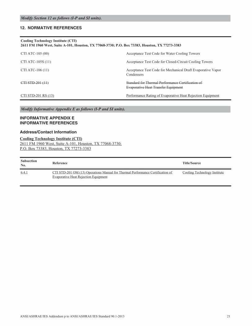
12. NORMATIVE REFERENCES
INFORMATIVE APPENDIX EINFORMATIVE REFERENCES
Address/Contact Information
Cooling Technology Institute (CTI)2611 FM 1960 West, Suite A-101, Houston, TX 77068-3730;P.O. Box 73383, Houston, TX 77273-3383
Modify Section 12 as follows (I-P and SI units).
Cooling Technology Institute (CTI)2611 FM 1960 West, Suite A-101, Houston, TX 77068-3730; P.O. Box 73383, Houston, TX 77273-3383
CTI ATC-105 (00) Acceptance Test Code for Water Cooling Towers
CTI ATC-105S (11) Acceptance Test Code for Closed-Circuit Cooling Towers
CTI ATC-106 (11) Acceptance Test Code for Mechanical Draft Evaporative VaporCondensers
CTI STD-201 (11) Standard for Thermal Performance Certification ofEvaporative Heat Transfer Equipment
CTI STD-201 RS (13) Performance Rating of Evaporative Heat Rejection Equipment
Modify Informative Appendix E as follows (I-P and SI units).
SubsectionNo.
Reference Title/Source
6.4.1 CTI STD-201 OM (13) Operations Manual for Thermal Performance Certification ofEvaporative Heat Rejection Equipment
Cooling Technology Institute
ANSI/ASHRAE/IES Addendum p to ANSI/ASHRAE/IES Standard 90.1-2013 21
22 ANSI/ASHRAE/IES Addendum q to ANSI/ASHRAE/IES Standard 90.1-2013
(This foreword is not part of this standard. It is merelyinformative and does not contain requirements necessaryfor conformance to the standard. It has not been pro-cessed according to the ANSI requirements for a standardand may contain material that has not been subject topublic review or a consensus process. Unresolved objec-tors on informative material are not offered the right toappeal at ASHRAE or ANSI.)
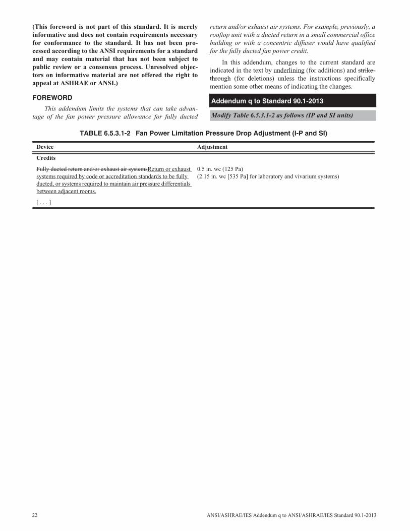
FOREWORD
This addendum limits the systems that can take advan-tage of the fan power pressure allowance for fully ducted
return and/or exhaust air systems. For example, previously, arooftop unit with a ducted return in a small commercial officebuilding or with a concentric diffuser would have qualifiedfor the fully ducted fan power credit.
In this addendum, changes to the current standard areindicated in the text by underlining (for additions) and strike-through (for deletions) unless the instructions specificallymention some other means of indicating the changes.
Addendum q to Standard 90.1-2013
Modify Table 6.5.3.1-2 as follows (IP and SI units)
TABLE 6.5.3.1-2 Fan Power Limitation Pressure Drop Adjustment (I-P and SI)
Device Adjustment
Credits
Fully ducted return and/or exhaust air systemsReturn or exhaustsystems required by code or accreditation standards to be fullyducted, or systems required to maintain air pressure differentialsbetween adjacent rooms.
0.5 in. wc (125 Pa)(2.15 in. wc [535 Pa] for laboratory and vivarium systems)
[ . . . ]
ANSI/ASHRAE/IES Addendum r to ANSI/ASHRAE/IES Standard 90.1-2013 23
(This foreword is not part of this standard. It is merelyinformative and does not contain requirements necessaryfor conformance to the standard. It has not been pro-cessed according to the ANSI requirements for a standardand may contain material that has not been subject topublic review or a consensus process. Unresolved objec-tors on informative material are not offered the right toappeal at ASHRAE or ANSI.)
FOREWORD
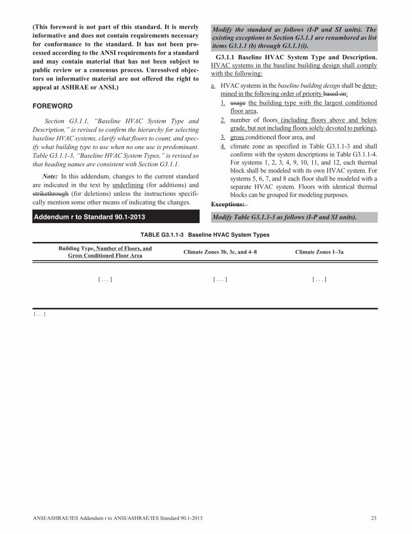
Section G3.1.1, “Baseline HVAC System Type andDescription,” is revised to confirm the hierarchy for selectingbaseline HVAC systems, clarify what floors to count, and spec-ify what building type to use when no one use is predominant.Table G3.1.1-3, “Baseline HVAC System Types,” is revised sothat heading names are consistent with Section G3.1.1.
Note: In this addendum, changes to the current standardare indicated in the text by underlining (for additions) andstrikethrough (for deletions) unless the instructions specifi-cally mention some other means of indicating the changes.
G3.1.1 Baseline HVAC System Type and Description.HVAC systems in the baseline building design shall complywith the following:
a. HVAC systems in the baseline building design shall be deter-mined in the following order of priority based on:1. usage the building type with the largest conditioned
floor area,2. number of floors (including floors above and below
grade, but not including floors solely devoted to parking),3. gross conditioned floor area, and4. climate zone as specified in Table G3.1.1-3 and shall
conform with the system descriptions in Table G3.1.1-4.For systems 1, 2, 3, 4, 9, 10, 11, and 12, each thermalblock shall be modeled with its own HVAC system. Forsystems 5, 6, 7, and 8 each floor shall be modeled with aseparate HVAC system. Floors with identical thermalblocks can be grouped for modeling purposes.
Exceptions:
Addendum r to Standard 90.1-2013
Modify the standard as follows (I-P and SI units). Theexisting exceptions to Section G3.1.1 are renumbered as listitems G3.1.1 (b) through G3.1.1(i).
Modify Table G3.1.1-3 as follows (I-P and SI units).
TABLE G3.1.1-3 Baseline HVAC System Types
Building Type, Number of Floors, andGross Conditioned Floor Area
Climate Zones 3b, 3c, and 4–8 Climate Zones 1–3a
[ . . . ] [ . . . ] [ . . . ]
[ . . . ]
24 ANSI/ASHRAE/IES Addendum s to ANSI/ASHRAE/IES Standard 90.1-2013
(This foreword is not part of this standard. It is merelyinformative and does not contain requirements necessaryfor conformance to the standard. It has not been pro-cessed according to the ANSI requirements for a standardand may contain material that has not been subject topublic review or a consensus process. Unresolved objec-tors on informative material are not offered the right toappeal at ASHRAE or ANSI.)
FOREWORD
Exception 2 to 6.5.2.1 addresses single-duct VAV reheatsystems with DDC. It unintentionally places undue require-ments on other VAV systems with DDC that have an alternatemeans of heating, such as fan-powered boxes, dual duct, andbaseboard, and even non-VAV systems, such as DOAS withradiant or chilled beams. This is resolved by making Excep-tion 1 also apply to systems with DDC but with lower reheatminimums as compared to systems without DDC (e.g., pneu-matic control). This would allow, for example, a fan-poweredbox with a 20% minimum on the primary air.
Note: In this addendum, changes to the current standardare indicated in the text by underlining (for additions) andstrikethrough (for deletions) unless the instructions specifi-cally mention some other means of indicating the changes.
Exceptions:1. Zones without DDC for which the volume of air
that is reheated, recooled, or mixed is less than thelarger of the following:a. 20% of the zone design peak supply for systems
with DDC and 30% of the zone design peaksupply rate for other systems
Addendum s to Standard 90.1-2013
Modify Exception 1 to Section 6.5.2.1, “Zone Controls.” (I-P and SI units).
ANSI/ASHRAE/IES Addendum z to ANSI/ASHRAE/IES Standard 90.1-2013 25
(This foreword is not part of this standard. It is merelyinformative and does not contain requirements necessaryfor conformance to the standard. It has not been pro-cessed according to the ANSI requirements for a standardand may contain material that has not been subject topublic review or a consensus process. Unresolved objec-tors on informative material are not offered the right toappeal at ASHRAE or ANSI.)
FOREWORD
This addendum clarifies and modifies the modeling of abaseline HVAC system with air-source heat pumps and elec-tric auxiliary heat. Thermostat “stages,” as described in thecurrent text, may not be applicable to variable-speed equip-ment, resulting in confusion about how to model the system.Rather than using auxiliary heat on the last thermostat stageand when the outdoor temperature is less than 40°F (4°C),auxiliary heat is used in all hours with outdoor temperaturesbelow 40°F (4°C). In addition, the revision clarifies that theheat pump shall be modeled to continue operation while aux-iliary heat is used.
It should be noted that electric air-source heat pumps areonly used as the baseline system for Climate Zones 1 through
3. While it is probably unrealistic to model air-source heatpumps as continuing to operate in extremely low temperatureconditions, relatively few locations in Climate Zones 1through 3 experience heating design temperatures lower than15°F (–9°C).
In this addendum, changes to the current standard areindicated in the text by underlining (for additions) and strike-through (for deletions) unless the instructions specificallymention some other means of indicating the changes.
G3.1.3.1 Heat Pumps (Systems 2 and 4). Electric air-source heat pumps shall be modeled with electric auxiliaryheat and an outdoor air thermostat. The systems shall becontrolled with multistage space thermostats and an outdoorair thermostat wired to energize auxiliary heat only on thelast thermostat stage and when the outdoor air temperature isless than 40°F (4°C). The air-source heat pump shall be mod-eled to continue to operate while auxiliary heat is energized.
Addendum z to Standard 90.1-2013
Revise the standard as follows (IP and SI units).
26 ANSI/ASHRAE/IES Addendum aa to ANSI/ASHRAE/IES Standard 90.1-2013
(This foreword is not part of this standard. It is merelyinformative and does not contain requirements necessaryfor conformance to the standard. It has not been pro-cessed according to the ANSI requirements for a standardand may contain material that has not been subject topublic review or a consensus process. Unresolved objec-tors on informative material are not offered the right toappeal at ASHRAE or ANSI.)
FOREWORD
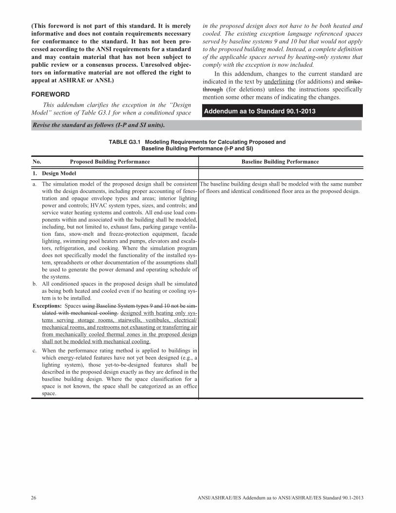
This addendum clarifies the exception in the “DesignModel” section of Table G3.1 for when a conditioned space
in the proposed design does not have to be both heated andcooled. The existing exception language referenced spacesserved by baseline systems 9 and 10 but that would not applyto the proposed building model. Instead, a complete definitionof the applicable spaces served by heating-only systems thatcomply with the exception is now included.
In this addendum, changes to the current standard areindicated in the text by underlining (for additions) and strike-through (for deletions) unless the instructions specificallymention some other means of indicating the changes.
Addendum aa to Standard 90.1-2013
Revise the standard as follows (I-P and SI units).
TABLE G3.1 Modeling Requirements for Calculating Proposed andBaseline Building Performance (I-P and SI)
No. Proposed Building Performance Baseline Building Performance
1. Design Model
a. The simulation model of the proposed design shall be consistentwith the design documents, including proper accounting of fenes-tration and opaque envelope types and areas; interior lightingpower and controls; HVAC system types, sizes, and controls; andservice water heating systems and controls. All end-use load com-ponents within and associated with the building shall be modeled,including, but not limited to, exhaust fans, parking garage ventila-tion fans, snow-melt and freeze-protection equipment, facadelighting, swimming pool heaters and pumps, elevators and escala-tors, refrigeration, and cooking. Where the simulation programdoes not specifically model the functionality of the installed sys-tem, spreadsheets or other documentation of the assumptions shallbe used to generate the power demand and operating schedule ofthe systems.
b. All conditioned spaces in the proposed design shall be simulatedas being both heated and cooled even if no heating or cooling sys-tem is to be installed.
Exceptions: Spaces using Baseline System types 9 and 10 not be sim-ulated with mechanical cooling. designed with heating only sys-tems serving storage rooms, stairwells, vestibules, electrical/mechanical rooms, and restrooms not exhausting or transferring airfrom mechanically cooled thermal zones in the proposed designshall not be modeled with mechanical cooling.
c. When the performance rating method is applied to buildings inwhich energy-related features have not yet been designed (e.g., alighting system), those yet-to-be-designed features shall bedescribed in the proposed design exactly as they are defined in thebaseline building design. Where the space classification for aspace is not known, the space shall be categorized as an officespace.
The baseline building design shall be modeled with the same numberof floors and identical conditioned floor area as the proposed design.
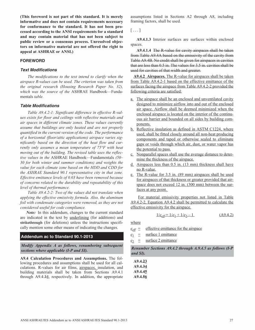
(This foreword is not part of this standard. It is merelyinformative and does not contain requirements necessaryfor conformance to the standard. It has not been pro-cessed according to the ANSI requirements for a standardand may contain material that has not been subject topublic review or a consensus process. Unresolved objec-tors on informative material are not offered the right toappeal at ASHRAE or ANSI.)
FOREWORD
Text Modifications
The modifications to the text intend to clarify when theairspace R-values can be used. The criterion was taken fromthe original research (Housing Research Paper No. 32),which was the source of the ASHRAE Handbook—Funda-mentals table.
Table Modifications
Table A9.4.2-1: Significant difference in effective R-val-ues exists for floor and ceilings with reflective materials andair spaces in different climate zones. These values currentlyassume that buildings are only heated and are not properlyquantified in the current version of the code. The performanceof a horizontal (floor/attic applications) airspace varies sig-nificantly based on the direction of the heat flow and cur-rently only assumes a mean temperature of 75°F with heatmoving out of the building. The revised table uses the reflec-tive values in the ASHRAE Handbook—Fundamentals (50–30 for both winter and summer conditions) and weights thevalue for each climate zone based on the HDD and CDD forthe ASHRAE Standard 90.1 representative city in that zone.Effective emittance levels of 0.03 have been removed becauseof concerns related to the durability and repeatability of thislevel of thermal performance.
Table A9.4.2-2: Two of the values did not translate whenapplying the effective emissivity formula. Also, the aluminumfoil with condensate categories were removed, as they are notconsidered useful for code compliance.
Note: In this addendum, changes to the current standardare indicated in the text by underlining (for additions) andstrikethrough (for deletions) unless the instructions specifi-cally mention some other means of indicating the changes.
A9.4 Calculation Procedures and Assumptions. The fol-lowing procedures and assumptions shall be used for all cal-culations. R-values for air films, airspaces, insulation, andbuilding materials shall be taken from Sections A9.4.1through A9.4.34, respectively. In addition, the appropriate
assumptions listed in Sections A2 through A8, includingframing factors, shall be used.
[ . . . ]
A9.4.1.3 Interior surfaces are surfaces within enclosedspaces.
A9.4.1.4 The R-value for cavity airspaces shall be takenfrom Table A9.4A based on the emissivity of the cavity fromTable A9.4B. No credit shall be given for airspaces in cavitiesthat are less than 0.5 in. The values for 3.5 in. cavities shall beused for cavities of that width and greater.
A9.4.2 Airspaces. The R-value for airspaces shall be takenfrom Table A9.4.2-1 based on the effective emittance of thesurfaces facing the airspace from Table A9.4.2-2 provided thefollowing criteria are satisfied:
a. The airspace shall be an enclosed and unventilated cavitydesigned to minimize airflow into and out of the enclosedair space. Airflow shall be deemed minimized when theenclosed airspace is located on the interior of the continu-ous air barrier and bounded on all sides by building com-ponents.
b. Reflective insulation as defined in ASTM C1224, whereused, shall be fitted closely around all non-heat producingcomponents and taped or otherwise sealed to eliminategaps or voids through which air, dust, or water vapor hasthe potential to pass.
c. Nonparallel spaces shall use the average distance to deter-mine the thickness of the airspace.
d. Airspaces less than 0.5 in. (13 mm) thickness shall haveno R-value.
e. The R-value for 3.5 in. (89 mm) airspaces shall be usedfor airspaces of that thickness or greater provided that air-space does not exceed 12 in. (300 mm) between the sur-faces at any point.
For material emissivity properties not listed in TableA9.4.2-2, Equation A9.4.2 shall be permitted to calculate theeffective emissivity for the airspace.
1/eeff = 1/e1 + 1/e2 – 1 (A9.4.2)
where
eeff = effective emittance for the airspace
e1 = surface 1 emittance
e2 = surface 2 emittance
A9.4.23A9.4.34A9.4.45A9.4.56
Addendum ac to Standard 90.1-2013
Modify Appendix A as follows, renumbering subsequentsections where applicable (I-P and SI). Renumber Sections A9.4.2 through A.9.4.5 as follows (I-P
and SI).
ANSI/ASHRAE/IES Addendum ac to ANSI/ASHRAE/IES Standard 90.1-2013 27
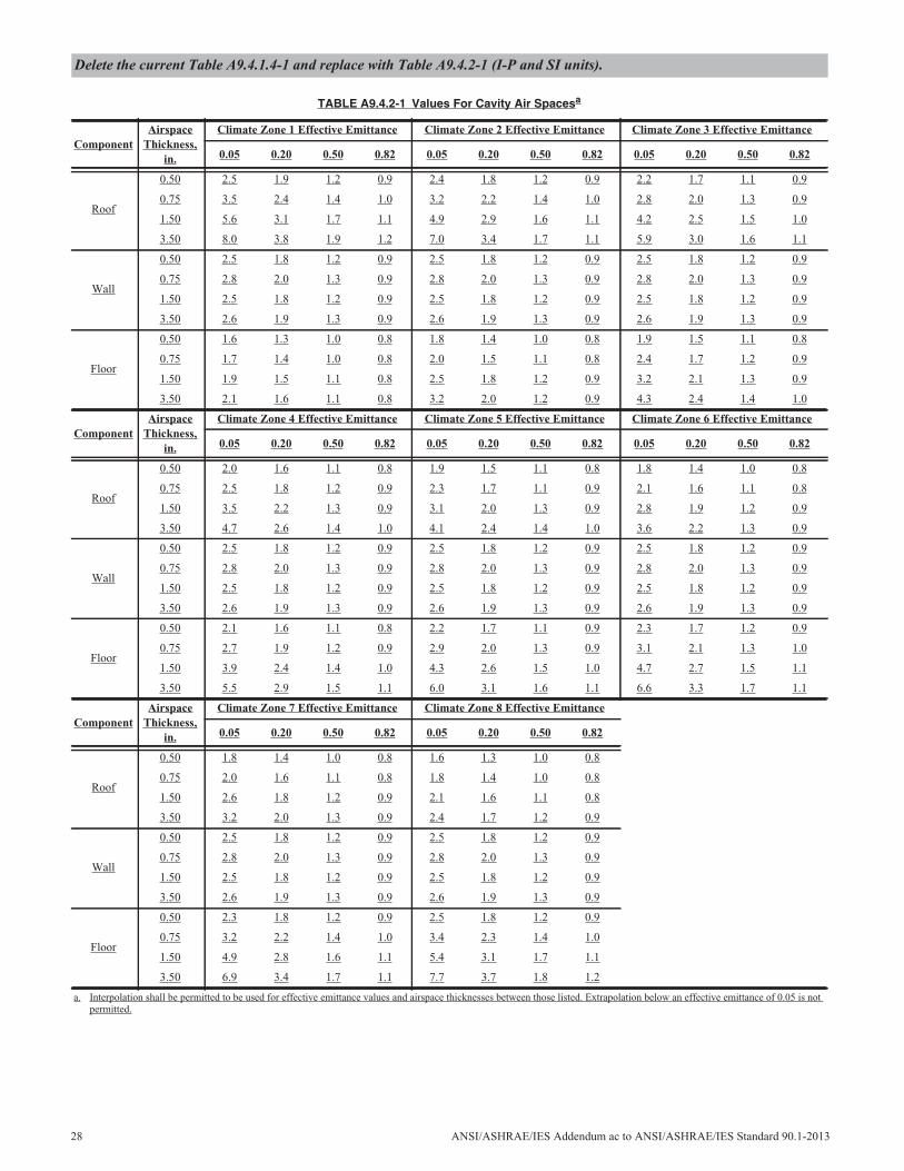
Delete the current Table A9.4.1.4-1 and replace with Table A9.4.2-1 (I-P and SI units).
TABLE A9.4.2-1 Values For Cavity Air Spacesa
ComponentAirspace
Thickness,in.
Climate Zone 1 Effective Emittance Climate Zone 2 Effective Emittance Climate Zone 3 Effective Emittance
0.05 0.20 0.50 0.82 0.05 0.20 0.50 0.82 0.05 0.20 0.50 0.82
Roof
0.50 2.5 1.9 1.2 0.9 2.4 1.8 1.2 0.9 2.2 1.7 1.1 0.9
0.75 3.5 2.4 1.4 1.0 3.2 2.2 1.4 1.0 2.8 2.0 1.3 0.9
1.50 5.6 3.1 1.7 1.1 4.9 2.9 1.6 1.1 4.2 2.5 1.5 1.0
3.50 8.0 3.8 1.9 1.2 7.0 3.4 1.7 1.1 5.9 3.0 1.6 1.1
Wall
0.50 2.5 1.8 1.2 0.9 2.5 1.8 1.2 0.9 2.5 1.8 1.2 0.9
0.75 2.8 2.0 1.3 0.9 2.8 2.0 1.3 0.9 2.8 2.0 1.3 0.9
1.50 2.5 1.8 1.2 0.9 2.5 1.8 1.2 0.9 2.5 1.8 1.2 0.9
3.50 2.6 1.9 1.3 0.9 2.6 1.9 1.3 0.9 2.6 1.9 1.3 0.9
Floor
0.50 1.6 1.3 1.0 0.8 1.8 1.4 1.0 0.8 1.9 1.5 1.1 0.8
0.75 1.7 1.4 1.0 0.8 2.0 1.5 1.1 0.8 2.4 1.7 1.2 0.9
1.50 1.9 1.5 1.1 0.8 2.5 1.8 1.2 0.9 3.2 2.1 1.3 0.9
3.50 2.1 1.6 1.1 0.8 3.2 2.0 1.2 0.9 4.3 2.4 1.4 1.0
ComponentAirspace
Thickness,in.
Climate Zone 4 Effective Emittance Climate Zone 5 Effective Emittance Climate Zone 6 Effective Emittance
0.05 0.20 0.50 0.82 0.05 0.20 0.50 0.82 0.05 0.20 0.50 0.82
Roof
0.50 2.0 1.6 1.1 0.8 1.9 1.5 1.1 0.8 1.8 1.4 1.0 0.8
0.75 2.5 1.8 1.2 0.9 2.3 1.7 1.1 0.9 2.1 1.6 1.1 0.8
1.50 3.5 2.2 1.3 0.9 3.1 2.0 1.3 0.9 2.8 1.9 1.2 0.9
3.50 4.7 2.6 1.4 1.0 4.1 2.4 1.4 1.0 3.6 2.2 1.3 0.9
Wall
0.50 2.5 1.8 1.2 0.9 2.5 1.8 1.2 0.9 2.5 1.8 1.2 0.9
0.75 2.8 2.0 1.3 0.9 2.8 2.0 1.3 0.9 2.8 2.0 1.3 0.9
1.50 2.5 1.8 1.2 0.9 2.5 1.8 1.2 0.9 2.5 1.8 1.2 0.9
3.50 2.6 1.9 1.3 0.9 2.6 1.9 1.3 0.9 2.6 1.9 1.3 0.9
Floor
0.50 2.1 1.6 1.1 0.8 2.2 1.7 1.1 0.9 2.3 1.7 1.2 0.9
0.75 2.7 1.9 1.2 0.9 2.9 2.0 1.3 0.9 3.1 2.1 1.3 1.0
1.50 3.9 2.4 1.4 1.0 4.3 2.6 1.5 1.0 4.7 2.7 1.5 1.1
3.50 5.5 2.9 1.5 1.1 6.0 3.1 1.6 1.1 6.6 3.3 1.7 1.1
ComponentAirspace
Thickness,in.
Climate Zone 7 Effective Emittance Climate Zone 8 Effective Emittance
0.05 0.20 0.50 0.82 0.05 0.20 0.50 0.82
Roof
0.50 1.8 1.4 1.0 0.8 1.6 1.3 1.0 0.8
0.75 2.0 1.6 1.1 0.8 1.8 1.4 1.0 0.8
1.50 2.6 1.8 1.2 0.9 2.1 1.6 1.1 0.8
3.50 3.2 2.0 1.3 0.9 2.4 1.7 1.2 0.9
Wall
0.50 2.5 1.8 1.2 0.9 2.5 1.8 1.2 0.9
0.75 2.8 2.0 1.3 0.9 2.8 2.0 1.3 0.9
1.50 2.5 1.8 1.2 0.9 2.5 1.8 1.2 0.9
3.50 2.6 1.9 1.3 0.9 2.6 1.9 1.3 0.9
Floor
0.50 2.3 1.8 1.2 0.9 2.5 1.8 1.2 0.9
0.75 3.2 2.2 1.4 1.0 3.4 2.3 1.4 1.0
1.50 4.9 2.8 1.6 1.1 5.4 3.1 1.7 1.1
3.50 6.9 3.4 1.7 1.1 7.7 3.7 1.8 1.2
a. Interpolation shall be permitted to be used for effective emittance values and airspace thicknesses between those listed. Extrapolation below an effective emittance of 0.05 is notpermitted.
28 ANSI/ASHRAE/IES Addendum ac to ANSI/ASHRAE/IES Standard 90.1-2013
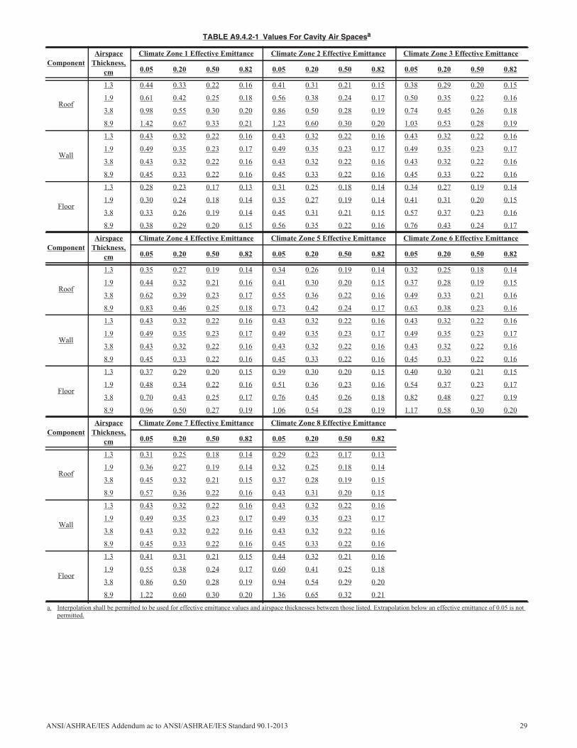
TABLE A9.4.2-1 Values For Cavity Air Spacesa
ComponentAirspace
Thickness,cm
Climate Zone 1 Effective Emittance Climate Zone 2 Effective Emittance Climate Zone 3 Effective Emittance
0.05 0.20 0.50 0.82 0.05 0.20 0.50 0.82 0.05 0.20 0.50 0.82
Roof
1.3 0.44 0.33 0.22 0.16 0.41 0.31 0.21 0.15 0.38 0.29 0.20 0.15
1.9 0.61 0.42 0.25 0.18 0.56 0.38 0.24 0.17 0.50 0.35 0.22 0.16
3.8 0.98 0.55 0.30 0.20 0.86 0.50 0.28 0.19 0.74 0.45 0.26 0.18
8.9 1.42 0.67 0.33 0.21 1.23 0.60 0.30 0.20 1.03 0.53 0.28 0.19
Wall
1.3 0.43 0.32 0.22 0.16 0.43 0.32 0.22 0.16 0.43 0.32 0.22 0.16
1.9 0.49 0.35 0.23 0.17 0.49 0.35 0.23 0.17 0.49 0.35 0.23 0.17
3.8 0.43 0.32 0.22 0.16 0.43 0.32 0.22 0.16 0.43 0.32 0.22 0.16
8.9 0.45 0.33 0.22 0.16 0.45 0.33 0.22 0.16 0.45 0.33 0.22 0.16
Floor
1.3 0.28 0.23 0.17 0.13 0.31 0.25 0.18 0.14 0.34 0.27 0.19 0.14
1.9 0.30 0.24 0.18 0.14 0.35 0.27 0.19 0.14 0.41 0.31 0.20 0.15
3.8 0.33 0.26 0.19 0.14 0.45 0.31 0.21 0.15 0.57 0.37 0.23 0.16
8.9 0.38 0.29 0.20 0.15 0.56 0.35 0.22 0.16 0.76 0.43 0.24 0.17
ComponentAirspace
Thickness,cm
Climate Zone 4 Effective Emittance Climate Zone 5 Effective Emittance Climate Zone 6 Effective Emittance
0.05 0.20 0.50 0.82 0.05 0.20 0.50 0.82 0.05 0.20 0.50 0.82
Roof
1.3 0.35 0.27 0.19 0.14 0.34 0.26 0.19 0.14 0.32 0.25 0.18 0.14
1.9 0.44 0.32 0.21 0.16 0.41 0.30 0.20 0.15 0.37 0.28 0.19 0.15
3.8 0.62 0.39 0.23 0.17 0.55 0.36 0.22 0.16 0.49 0.33 0.21 0.16
8.9 0.83 0.46 0.25 0.18 0.73 0.42 0.24 0.17 0.63 0.38 0.23 0.16
Wall
1.3 0.43 0.32 0.22 0.16 0.43 0.32 0.22 0.16 0.43 0.32 0.22 0.16
1.9 0.49 0.35 0.23 0.17 0.49 0.35 0.23 0.17 0.49 0.35 0.23 0.17
3.8 0.43 0.32 0.22 0.16 0.43 0.32 0.22 0.16 0.43 0.32 0.22 0.16
8.9 0.45 0.33 0.22 0.16 0.45 0.33 0.22 0.16 0.45 0.33 0.22 0.16
Floor
1.3 0.37 0.29 0.20 0.15 0.39 0.30 0.20 0.15 0.40 0.30 0.21 0.15
1.9 0.48 0.34 0.22 0.16 0.51 0.36 0.23 0.16 0.54 0.37 0.23 0.17
3.8 0.70 0.43 0.25 0.17 0.76 0.45 0.26 0.18 0.82 0.48 0.27 0.19
8.9 0.96 0.50 0.27 0.19 1.06 0.54 0.28 0.19 1.17 0.58 0.30 0.20
ComponentAirspace
Thickness,cm
Climate Zone 7 Effective Emittance Climate Zone 8 Effective Emittance
0.05 0.20 0.50 0.82 0.05 0.20 0.50 0.82
Roof
1.3 0.31 0.25 0.18 0.14 0.29 0.23 0.17 0.13
1.9 0.36 0.27 0.19 0.14 0.32 0.25 0.18 0.14
3.8 0.45 0.32 0.21 0.15 0.37 0.28 0.19 0.15
8.9 0.57 0.36 0.22 0.16 0.43 0.31 0.20 0.15
Wall
1.3 0.43 0.32 0.22 0.16 0.43 0.32 0.22 0.16
1.9 0.49 0.35 0.23 0.17 0.49 0.35 0.23 0.17
3.8 0.43 0.32 0.22 0.16 0.43 0.32 0.22 0.16
8.9 0.45 0.33 0.22 0.16 0.45 0.33 0.22 0.16
Floor
1.3 0.41 0.31 0.21 0.15 0.44 0.32 0.21 0.16
1.9 0.55 0.38 0.24 0.17 0.60 0.41 0.25 0.18
3.8 0.86 0.50 0.28 0.19 0.94 0.54 0.29 0.20
8.9 1.22 0.60 0.30 0.20 1.36 0.65 0.32 0.21
a. Interpolation shall be permitted to be used for effective emittance values and airspace thicknesses between those listed. Extrapolation below an effective emittance of 0.05 is notpermitted.
ANSI/ASHRAE/IES Addendum ac to ANSI/ASHRAE/IES Standard 90.1-2013 29
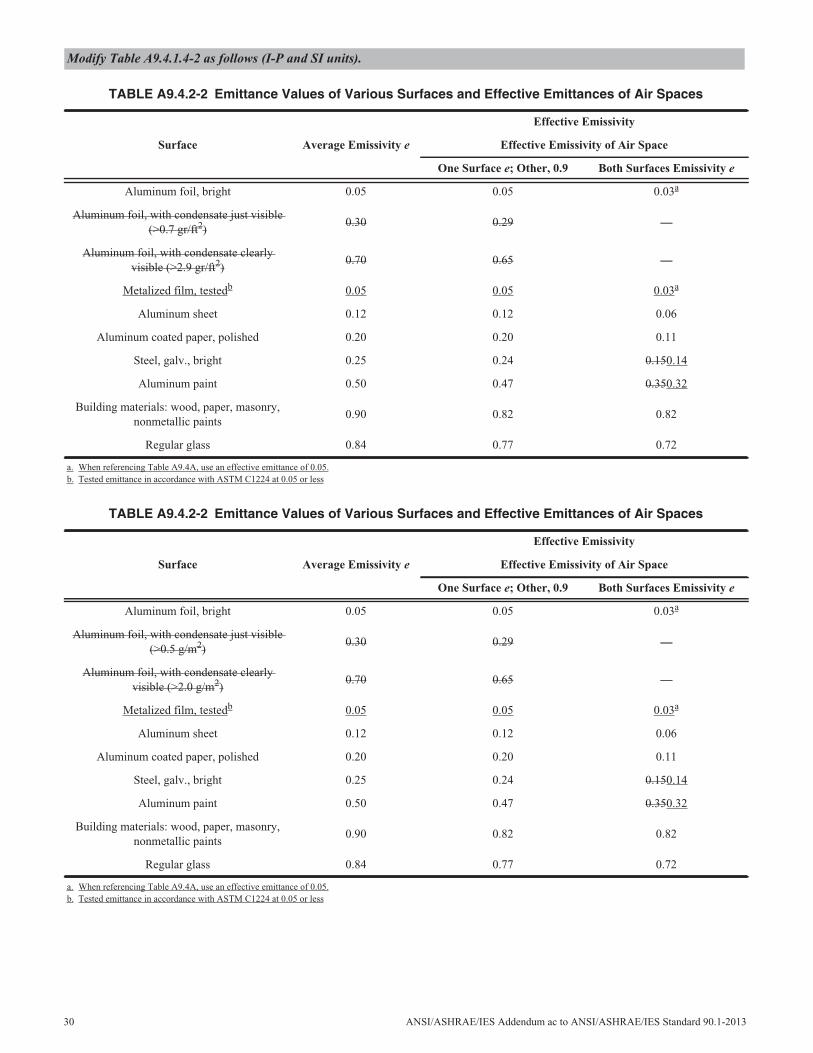
Modify Table A9.4.1.4-2 as follows (I-P and SI units).
TABLE A9.4.2-2 Emittance Values of Various Surfaces and Effective Emittances of Air Spaces
Surface Average Emissivity e
Effective Emissivity
Effective Emissivity of Air Space
One Surface e; Other, 0.9 Both Surfaces Emissivity e
Aluminum foil, bright 0.05 0.05 0.03a
Aluminum foil, with condensate just visible(>0.7 gr/ft2)
0.30 0.29 —
Aluminum foil, with condensate clearlyvisible (>2.9 gr/ft2)
0.70 0.65 —
Metalized film, testedb 0.05 0.05 0.03a
Aluminum sheet 0.12 0.12 0.06
Aluminum coated paper, polished 0.20 0.20 0.11
Steel, galv., bright 0.25 0.24 0.150.14
Aluminum paint 0.50 0.47 0.350.32
Building materials: wood, paper, masonry,nonmetallic paints
0.90 0.82 0.82
Regular glass 0.84 0.77 0.72
a. When referencing Table A9.4A, use an effective emittance of 0.05.b. Tested emittance in accordance with ASTM C1224 at 0.05 or less
TABLE A9.4.2-2 Emittance Values of Various Surfaces and Effective Emittances of Air Spaces
Surface Average Emissivity e
Effective Emissivity
Effective Emissivity of Air Space
One Surface e; Other, 0.9 Both Surfaces Emissivity e
Aluminum foil, bright 0.05 0.05 0.03a
Aluminum foil, with condensate just visible(>0.5 g/m2)
0.30 0.29 —
Aluminum foil, with condensate clearlyvisible (>2.0 g/m2)
0.70 0.65 —
Metalized film, testedb 0.05 0.05 0.03a
Aluminum sheet 0.12 0.12 0.06
Aluminum coated paper, polished 0.20 0.20 0.11
Steel, galv., bright 0.25 0.24 0.150.14
Aluminum paint 0.50 0.47 0.350.32
Building materials: wood, paper, masonry,nonmetallic paints
0.90 0.82 0.82
Regular glass 0.84 0.77 0.72
a. When referencing Table A9.4A, use an effective emittance of 0.05.b. Tested emittance in accordance with ASTM C1224 at 0.05 or less
30 ANSI/ASHRAE/IES Addendum ac to ANSI/ASHRAE/IES Standard 90.1-2013
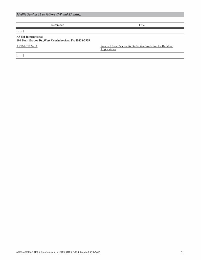
Modify Section 12 as follows (I-P and SI units).
Reference Title
[ . . . ]
ASTM International100 Barr Harbor Dr.,West Conshohocken, PA 19428-2959
ASTM C1224-11 Standard Specification for Reflective Insulation for BuildingApplications
[ . . . ]
ANSI/ASHRAE/IES Addendum ac to ANSI/ASHRAE/IES Standard 90.1-2013 31
32 ANSI/ASHRAE/IES Addendum ad to ANSI/ASHRAE/IES Standard 90.1-2013
(This foreword is not part of this standard. It is merelyinformative and does not contain requirements necessaryfor conformance to the standard. It has not been pro-cessed according to the ANSI requirements for a standardand may contain material that has not been subject topublic review or a consensus process. Unresolved objec-tors on informative material are not offered the right toappeal at ASHRAE or ANSI.)
FOREWORD
This addendum revises the preheat coil requirement forthe Baseline Building model in Appendix G to apply to onlysystem types that would logically employ the use of one (base-line system types 5 through 8). The fixed setpoint control elim-inates any potential simultaneous cooling and heating by thesystem cooling coil and preheat coil. Since the preheat coilrequirement is now a system-specific requirement, this sectionwas moved to Section G3.1.3.19.
In this addendum, changes to the current standard areindicated in the text by underlining (for additions) and strike-through (for deletions) unless the instructions specificallymention some other means of indicating the changes.
G3.1.2.4 (Not Used) Preheat Coils. If the HVAC systemin the proposed design has a preheat coil and a preheat coilcan be modeled in the baseline system, the baseline systemshall be modeled with a preheat coil controlled in the samemanner as the proposed design.
G3.1.3.19 Preheat Coils (Systems 5 through 8). Thebaseline system shall be modeled with a preheat coil con-trolled to a fixed setpoint 20°F (11°C) less than the designroom heating temperature setpoint.
Addendum ad to Standard 90.1-2013
Revise the standard as follows (I-P and SI units).
ANSI/ASHRAE/IES Addendum ae to ANSI/ASHRAE/IES Standard 90.1-2013 33
(This foreword is not part of this standard. It is merelyinformative and does not contain requirements necessaryfor conformance to the standard. It has not been pro-cessed according to the ANSI requirements for a standardand may contain material that has not been subject topublic review or a consensus process. Unresolved objec-tors on informative material are not offered the right toappeal at ASHRAE or ANSI.)
FOREWORD
This addendum updates Section 3.2 text for the defini-tions used with motors and Section 10.4.1 text for small elec-tric motors. Many small motors provide information on theinput and output power, and the revision to definitions clari-fies the power rating used for efficiency requirements of small(and large) electric motors.
The changes to Section 10.4.1 help to clarify that special-ized small electric motors, used in niche applications, do nothave efficiency requirements in Tables 10.8-4 and 10.8-5.
These modifications are editorial and do not change anyof the efficiency values in the tables.
In this addendum, changes to the current standard areindicated in the text by underlining (for additions) and strike-through (for deletions) unless the instructions specificallymention some other means of indicating the changes.
3.2 Definitions
nameplate horsepower (hp): the nominal motor output powerhorsepower rating stamped on the motor nameplate.
10.4.1 Electric Motors. [ . . . ]General purpose Ssmall electric motors with a an output
power rating of 0.25 hp or more, and less than or equal to 3hp, shall have a minimum average full-load efficiency that isnot less than as shown in Table 10.8-4 for polyphase smallelectric motors and Table 10.8-5 for capacitor-start capacitor-run small electric motors and capacitor-start induction runsmall electric motors.
[ . . . ]
nameplate kilowatts (kW): the nominal motor shaft outputpower kilowatt rating stamped on the motor nameplate.
10.4.1 Electric Motors. [ . . . ]General purpose Ssmall electric motors with a an output
power rating of 0.19 kW or more, and less than or equal to 2.2kW, shall have a minimum average full-load efficiency that isnot less than as shown in Table 10.8-4 for polyphase smallelectric motors and Table 10.8-5 for capacitor-start capacitor-run small electric motors and capacitor-start induction runsmall electric motors.
[ . . . ]
Addendum ae to Standard 90.1-2013
Revise Section 3.2 as follows (I-P units).
Revise Section 10.4.1 as follows (I-P units).
Revise Section 3.2 as follows (SI units).
Revise Section 10.4.1 as follows (SI units).
34 ANSI/ASHRAE/IES Addendum ag to ANSI/ASHRAE/IES Standard 90.1-2013
(This foreword is not part of this standard. It is merelyinformative and does not contain requirements necessaryfor conformance to the standard. It has not been pro-cessed according to the ANSI requirements for a standardand may contain material that has not been subject topublic review or a consensus process. Unresolved objec-tors on informative material are not offered the right toappeal at ASHRAE or ANSI.)
FOREWORD
Vestibules are installed to reduce infiltration into thebuilding. The benefit of a vestibule during the cooling seasonis negated if the vestibule is cooled to the cooling setpoint ofthe adjacent space. This addendum limits mechanical coolingfor vestibules. An exception for temperature limits is allowedwhen the vestibule is tempered with transfer air or heatedwith recovered energy. Transfer air tempering is beneficialbecause that conditioned air is destined to be exhausted any-way, and pressurizing the vestibule may reduce infiltrationfurther. Little cost is added for this measure, as it requiresonly a reconfiguration of required controls.
In this addendum, changes to the current standard areindicated in the text by underlining (for additions) and strike-through (for deletions) unless the instructions specificallymention some other means of indicating the changes.
6.4.3.9 Heated or Cooled Vestibules Heating in Vesti-bules. Heating for vestibules, in accordance with Section5.4.3.4, and for air curtains with integral heating shall includeautomatic controls configured to shut off the heating systemwhen outdoor air temperatures are above 45°F (7°C). Vesti-bule heating and cooling systems shall also be controlled by athermostat in the vestibule with a setpoint that limitsed heat-ing to a maximum of 60°F (16°C) and cooling to a minimumof 85°F (29°C).
Exception: Vestibules with no hHeating or cooling pro-vided by site-recovered energy or by system or thatare tempered with transfer air that would otherwisebe exhausted.
Addendum ag to Standard 90.1-2013
Revise the standard as follows (IP and SI units)
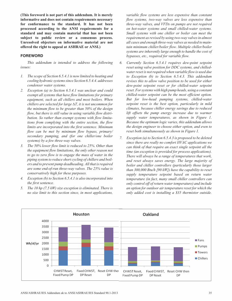
(This foreword is not part of this addendum. It is merelyinformative and does not contain requirements necessaryfor conformance to the standard. It has not beenprocessed according to the ANSI requirements for astandard and may contain material that has not beensubject to public review or a consensus process.Unresolved objectors on informative material are notoffered the right to appeal at ASHRAE or ANSI.)
FOREWORD
This addendum is intended to address the followingissues:
1. The scope of Section 6.5.4.1 is now limited to heating andcooling hydronic systems since Section 6.5.4.4. addressescondenser water systems.
2. Exception (a) to Section 6.5.4.1 was unclear and couldexempt all systems that have flow limitations for primaryequipment, such as all chillers and most boilers. Whenchillers are selected for large T, it is not uncommon forthe minimum flow to be greater than 50% of the designflow, but there is still value in using variable flow distri-bution. So rather than exempt systems with flow limita-tions from complying with the entire section, the flowlimits are incorporated into the first sentence. Minimumflow can be met by minimum flow bypass, primary/secondary pumping, and (for one chiller/one boilersystems) by a few three-way valves.
3. The 50% lower flow limit is reduced to 25%. Other thanthe equipment flow limitations, the only other reason notto go to zero flow is to engage the mass of water in thepiping system to reduce short cycling of chillers and boil-ers and to prevent pump deadheading. All that is requiredare some end-of-run three-way valves. The 25% value isconservatively high for these purposes.
4. Exception (b) to Section 6.5.4.1 is also incorporated intothe first sentence.
5. The 10 hp (7.5 kW) size exception is eliminated. There isno size limit to this section since, in most applications,
variable flow systems are less expensive than constantflow systems, two-way valves are less expensive thanthree-way valves, and VFDs on pumps are not requiredon hot-water systems and small chilled-water systems.Small systems with one chiller or boiler can meet therequirement as revised by using two-way valves in almostall cases and enough three-way valves as needed to main-tain minimum chiller/boiler flow. Multiple chiller/boilersystems are inherently large enough to handle the cost ofbypasses, etc., required for variable flow.
6. Currently Section 6.5.4.1 requires dew-point setpointreset using valve position for DDC systems, and chilled-water reset is not required when variable flow is used dueto Exception (b) to Section 6.5.4.3. This addendumrevises this to allow valve position to be used for eitherdew-point setpoint reset or for chilled-water setpointreset. For systems with high pump heads, using a constantchilled-water setpoint can be the most efficient option.But for low-head pumping systems, chilled-watersetpoint reset is the best option, particularly in mildclimates, because chiller energy savings due to reducedlift offsets the pump energy increase due to warmersupply water temperatures, as shown in Figure 1.Because the optimum logic varies, this addendum allowsthe design engineer to choose either option, and even toreset both simultaneously as shown in Figure 1.
7. Exception (a) to Section 6.5.4.3 is proposed to be deletedsince there are really no comfort HVAC applications wecan think of that require an exact single setpoint all thetime (an exception is provided for process applications).There will always be a range of temperatures that work,and reset always saves energy. The large majority ofboiler and chiller controllers (particularly those largerthan 300,000 Btu/h [90 kW]) have the capability to resetsupply temperature setpoint based on return watertemperature (in fact, many small chiller controllers canonly control off of return water temperature) and includean option for outdoor air temperature reset for which theonly added cost is installing a $35 thermistor outside.
ANSI/ASHRAE/IES Addendum ak to ANSI/ASHRAE/IES Standard 90.1-2013 35
One can simply limit the range of the reset to what theuser thinks is needed, but whatever the range, it will becost effective given there is little or no cost for this capa-bility.
8. Valve position reset of chilled- and hot-water tempera-tures is proposed to be required for DDC systems as notedabove. The range of the reset includes a clause “setpointlimits of the… application have been reached.” This is toallow someone to limit the reset for some perceived appli-cation limitation, one of the most common of which isdehumidification. In fact, there is no reason to limit resetfor dehumidification when valve position is used sincealmost the same supply air humidity condition (near satu-ration) will result when supply air temperature is main-tained, regardless of chilled-water temperature (this willbe explained further in the 2013 user’s manual). Thisclause is included to avoid negative feedback from thosewho might come up with an application that has tempera-ture limits.
9. An exception is added to eliminate chilled-water reset forsystems where the water is already cold, such as districtcooling or TES. Reset in this case will actually increaseenergy use by increasing pump energy without anycommensurate reduction in chiller energy.
Note: In this addendum, changes to the current standardare indicated in the text by underlining (for additions) andstrikethrough (for deletions) unless the instructions specifi-cally mention some other means of indicating the changes.
6.5.4.1 Hydronic Variable Flow Systems. HVACpumping Chilled- and hot-water distribution systems having atotal pump system power exceeding 10 hp [7.5 kW] thatinclude three (3) or more control valves designed to modulateor step open and close as a function of load shall be designedfor variable fluid flow and shall be capable of reducing pumpflow rates to no more than the larger of 5025% or less of thedesign flow rate or the minimum flow required by the heating/cooling equipment manufacturer for the proper operation ofequipment. Individual chilled water pumps serving variableflow systems having motors exceeding 5 hp (3.7 kW) shallhave controls and/or devices (such as variable speed control)that will result in pump motor demand of no more than 30%of design wattage at 50% of design water flow. The controls ordevices shall be controlled as a function of desired flow or tomaintain a minimum required differential pressure. Differen-
tial pressure shall be measured at or near the most remote heatexchanger or the heat exchanger requiring the greatest differ-ential pressure. The differential pressure setpoint shall be nomore than 110% of that required to achieve design flowthrough the heat exchanger. Where differential pressure con-trol is used to comply with this section and DDC controls areused the setpoint shall be reset downward based on valve posi-tions until one valve is nearly wide open.
Exceptions: Differential pressure setpoint reset is notrequired where valve position is used to comply withSection 6.5.4.3.
a. Systems where the minimum flow is less than theminimum flow required by the equipment manufac-turer for the proper operation of equipment served bythe system, such as chillers, and where total pumpsystem power is 75 hp or less.
b. Systems that include no more than three controlvalves.
[ . . . ]
6.5.4.3 Chilled- and Hot-Water Temperature ResetControls. Chilled- and hot-water systems with a designcapacity exceeding 300,000 Btu/h (90kW) supplying chilledor heated water (or both) to comfort conditioning systemsshall include controls that automatically reset supply watertemperatures by representative building loads (includingreturn water temperature) or by outdoor air temperature.Where DDC is used to control valves, the setpoint shall bereset based on valve positions until one valve is nearly wideopen or setpoint limits of the system equipment or applicationhave been reached.
Exceptions:
a. Where the supply temperature reset controls cannotbe implemented without causing improper operationof heating, cooling, humidifying, or dehumidifyingsystems.
b. Hydronic systems, such as those required by Section6.5.4.1 that use variable flow to reduce pumpingenergy.
a. Where chilled-water supply is already cold, such aschilled water supplied from a district cooling or ther-mal energy storage system, such that blending wouldbe required to achieve the reset chilled-water supplytemperature
b. Where a specific temperature is required for a pro-cess
c. Water temperature reset is not required where valveposition is used to comply with Section 6.5.4.1
Addendum ak to Standard 90.1-2013
Revise the standard as follows (I-P and SI units).
36 ANSI/ASHRAE/IES Addendum ak to ANSI/ASHRAE/IES Standard 90.1-2013
(This foreword is not part of this addendum. It is merelyinformative and does not contain requirements necessaryfor conformance to the standard. It has not beenprocessed according to the ANSI requirements for astandard and may contain material that has not beensubject to public review or a consensus process.Unresolved objectors on informative material are notoffered the right to appeal at ASHRAE or ANSI.)
FOREWORD
This addendum takes the requirements from 90.1-2004and makes them the baseline for modeling when usingAppendix G. In addition, it allows Appendix G to be used asa compliance path in 90.1 when models show the proposedbuilding is 45% more stringent than the 2004 baseline.
Note: In this addendum, changes to the current standardare indicated in the text by underlining (for additions) andstrikethrough (for deletions) unless the instructions specifi-cally mention some other means of indicating the changes.
3. DEFINITIONS, ABBREVIATIONS, ANDACRONYMS
[ . . . ]
baseline building design: a computer representation of ahypothetical design based on the proposed building project.This representation is used as the basis for calculating thebaseline building performance for rating above-standarddesign or when using the performance rating method as analternative path for minimum standard compliance in accor-dance with Section 4.2.1.1.
baseline building performance: the annual energy cost for abuilding design intended for use as a baseline for rating above-standard design or when using the performance rating methodas an alternative path for minimum standard compliance inaccordance with Section 4.2.1.1.
performance rating method: a calculation procedure thatgenerates an index of merit for the performance of buildingdesigns that substantially exceeds the energy efficiency levelsrequired by this standard or when using the performance ratingmethod as an alternative path for minimum standard compli-ance in accordance with Section 4.2.1.1.
rating authority: the organization, building official, or agencythat adopts, enforces, or sanctions use of this rating method-ology
regulated energy use: energy used by building systems andcomponents with requirements prescribed in Sections 5through 10. This includes energy used for HVAC, lighting,service water heating, motors, transformers, vertical trans-portation, refrigeration equipment, computer-room coolingequipment, and other building systems, components, andprocesses with requirements prescribed in Sections 5through 10.
unregulated energy use: energy used by building systems andcomponents that is not regulated energy use.
4.2 Compliance4.2.1 Compliance Paths
4.2.1.1 New Buildings. New buildings shall complywith either the provisions of
a. Sections 5, “Building Envelope”; Section 6, “Heating,Ventilating, and Air Conditioning”; Section 7, “ServiceWater Heating”; Section 8, “Power”; Section 9, “Light-ing”; and Section 10, “Other Equipment,” or
b. Section 11, “Energy Cost Budget Method,.” orc. Appendix G, “Performance Rating Method.”
When using Appendix G, the Performance Cost Index(PCI) shall be less than or equal to the Performance Cost IndexTarget (PCIt) when calculated in accordance with the following:
wherePCI = Performance Cost Index calculated in
accordance with Section G1.2.BBUEC = Baseline Building Unregulated Energy Cost.
The portion of the annual energy cost of abaseline building design that is due tounregulated energy use.
BBREC = Baseline Building Regulated Energy Cost. Theportion of the annual energy cost of a baselinebuilding design that is due to regulated energyuse.
BPF = Building Performance Factor from Table 4.2.1.1.For building area types not listed in Table 4.2.1.1use “All others.” Where a building has multiplebuilding area types, the required BPF shall beequal to the area-weighted average of thebuilding area types.
BBP = Baseline Building Performance.
Regulated energy cost shall be calculated by multiplyingthe total energy cost by the ratio of regulated energy use to totalenergy use for each fuel type. Unregulated energy cost shall becalculated by subtracting regulated energy cost from totalenergy cost.
G1. GENERAL
G1.1 Performance Rating Method Scope. This buildingperformance rating method is a modification of the EnergyCost Budget (ECB) Method in Section 11 and is intended foruse in rating the energy efficiency of building designs thatexceed the requirements of this standard. This appendix doesNOT offers an alternative compliance path for minimum stan-dard compliance per Section 4.2.1.1,; that is the intent of Sec-tion 11, Energy Cost Budget Method. Rather, this appendixand is also provided for those wishing to use the methodology
Addendum bm to Standard 90.1-2013
Revise Section 3 as follows (I-P and SI units).
Revise Section 4.2.1.1 as follows (I-P and SI units).
Revise Section G1 as follows (I-P and SI units).
PCIt BBUEC + BPF BBREC BBP=
ANSI/ASHRAE/IES Addendum bm to ANSI/ASHRAE/IES Standard 90.1-2013 37
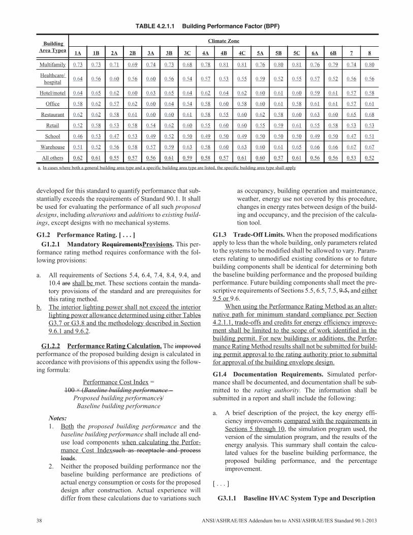
developed for this standard to quantify performance that sub-stantially exceeds the requirements of Standard 90.1. It shallbe used for evaluating the performance of all such proposeddesigns, including alterations and additions to existing build-ings, except designs with no mechanical systems.
G1.2 Performance Rating. [ . . . ]G1.2.1 Mandatory RequirementsProvisions. This per-
formance rating method requires conformance with the fol-lowing provisions:
a. All requirements of Sections 5.4, 6.4, 7.4, 8.4, 9.4, and10.4 are shall be met. These sections contain the manda-tory provisions of the standard and are prerequisites forthis rating method.
b. The interior lighting power shall not exceed the interiorlighting power allowance determined using either TablesG3.7 or G3.8 and the methodology described in Section9.6.1 and 9.6.2.
G1.2.2 Performance Rating Calculation. The improvedperformance of the proposed building design is calculated inaccordance with provisions of this appendix using the follow-ing formula:
Performance Cost Index =100 × (Baseline building performance –
Proposed building performance)/Baseline building performance
Notes:1. Both the proposed building performance and the
baseline building performance shall include all end-use load components when calculating the Perfor-mance Cost Indexsuch as receptacle and processloads.
2. Neither the proposed building performance nor thebaseline building performance are predictions ofactual energy consumption or costs for the proposeddesign after construction. Actual experience willdiffer from these calculations due to variations such
as occupancy, building operation and maintenance,weather, energy use not covered by this procedure,changes in energy rates between design of the build-ing and occupancy, and the precision of the calcula-tion tool.
G1.3 Trade-Off Limits. When the proposed modificationsapply to less than the whole building, only parameters relatedto the systems to be modified shall be allowed to vary. Param-eters relating to unmodified existing conditions or to futurebuilding components shall be identical for determining boththe baseline building performance and the proposed buildingperformance. Future building components shall meet the pre-scriptive requirements of Sections 5.5, 6.5, 7.5, 9.5, and either9.5 or 9.6.
When using the Performance Rating Method as an alter-native path for minimum standard compliance per Section4.2.1.1, trade-offs and credits for energy efficiency improve-ment shall be limited to the scope of work identified in thebuilding permit. For new buildings or additions, the Perfor-mance Rating Method results shall not be submitted for build-ing permit approval to the rating authority prior to submittalfor approval of the building envelope design.
G1.4 Documentation Requirements. Simulated perfor-mance shall be documented, and documentation shall be sub-mitted to the rating authority. The information shall besubmitted in a report and shall include the following:
a. A brief description of the project, the key energy effi-ciency improvements compared with the requirements inSections 5 through 10, the simulation program used, theversion of the simulation program, and the results of theenergy analysis. This summary shall contain the calcu-lated values for the baseline building performance, theproposed building performance, and the percentageimprovement.
[ . . . ]
G3.1.1 Baseline HVAC System Type and Description
TABLE 4.2.1.1 Building Performance Factor (BPF)
BuildingArea Typea
Climate Zone
1A 1B 2A 2B 3A 3B 3C 4A 4B 4C 5A 5B 5C 6A 6B 7 8
Multifamily 0.73 0.73 0.71 0.69 0.74 0.73 0.68 0.78 0.81 0.81 0.76 0.80 0.81 0.76 0.79 0.74 0.80
Healthcare/hospital
0.64 0.56 0.60 0.56 0.60 0.56 0.54 0.57 0.53 0.55 0.59 0.52 0.55 0.57 0.52 0.56 0.56
Hotel/motel 0.64 0.65 0.62 0.60 0.63 0.65 0.64 0.62 0.64 0.62 0.60 0.61 0.60 0.59 0.61 0.57 0.58
Office 0.58 0.62 0.57 0.62 0.60 0.64 0.54 0.58 0.60 0.58 0.60 0.61 0.58 0.61 0.61 0.57 0.61
Restaurant 0.62 0.62 0.58 0.61 0.60 0.60 0.61 0.58 0.55 0.60 0.62 0.58 0.60 0.63 0.60 0.65 0.68
Retail 0.52 0.58 0.53 0.58 0.54 0.62 0.60 0.55 0.60 0.60 0.55 0.59 0.61 0.55 0.58 0.53 0.53
School 0.46 0.53 0.47 0.53 0.49 0.52 0.50 0.49 0.50 0.49 0.50 0.50 0.50 0.49 0.50 0.47 0.51
Warehouse 0.51 0.52 0.56 0.58 0.57 0.59 0.63 0.58 0.60 0.63 0.60 0.61 0.65 0.66 0.66 0.67 0.67
All others 0.62 0.61 0.55 0.57 0.56 0.61 0.59 0.58 0.57 0.61 0.60 0.57 0.61 0.56 0.56 0.53 0.52
a. In cases where both a general building area type and a specific building area type are listed, the specific building area type shall apply
38 ANSI/ASHRAE/IES Addendum bm to ANSI/ASHRAE/IES Standard 90.1-2013
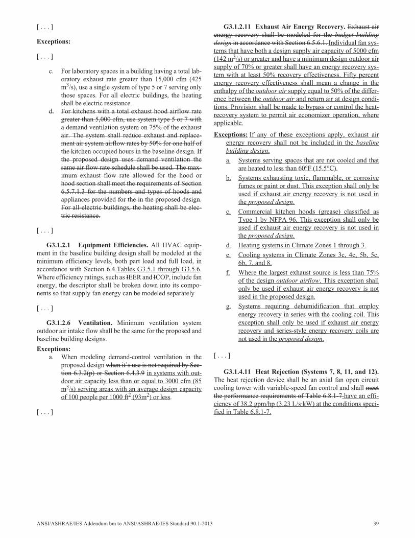
[ . . . ]
Exceptions:
[ . . . ]
c. For laboratory spaces in a building having a total lab-oratory exhaust rate greater than 15,000 cfm (425m3/s), use a single system of type 5 or 7 serving onlythose spaces. For all electric buildings, the heatingshall be electric resistance.
d. For kitchens with a total exhaust hood airflow rategreater than 5,000 cfm, use system type 5 or 7 witha demand ventilation system on 75% of the exhaustair. The system shall reduce exhaust and replace-ment air system airflow rates by 50% for one half ofthe kitchen occupied hours in the baseline design. Ifthe proposed design uses demand ventilation thesame air flow rate schedule shall be used. The max-imum exhaust flow rate allowed for the hood orhood section shall meet the requirements of Section6.5.7.1.3 for the numbers and types of hoods andappliances provided for the in the proposed design.For all-electric buildings, the heating shall be elec-tric resistance.
[ . . . ]
G3.1.2.1 Equipment Efficiencies. All HVAC equip-ment in the baseline building design shall be modeled at theminimum efficiency levels, both part load and full load, inaccordance with Section 6.4.Tables G3.5.1 through G3.5.6.Where efficiency ratings, such as IEER and ICOP, include fanenergy, the descriptor shall be broken down into its compo-nents so that supply fan energy can be modeled separately
[ . . . ]
G3.1.2.6 Ventilation. Minimum ventilation systemoutdoor air intake flow shall be the same for the proposed andbaseline building designs.
Exceptions:a. When modeling demand-control ventilation in the
proposed design when it’s use is not required by Sec-tion 6.3.2(p) or Section 6.4.3.9 in systems with out-door air capacity less than or equal to 3000 cfm (85m3/s) serving areas with an average design capacityof 100 people per 1000 ft2 (93m2) or less.
[ . . . ]
G3.1.2.11 Exhaust Air Energy Recovery. Exhaust airenergy recovery shall be modeled for the budget buildingdesign in accordance with Section 6.5.6.1. Individual fan sys-tems that have both a design supply air capacity of 5000 cfm(142 m3/s) or greater and have a minimum design outdoor airsupply of 70% or greater shall have an energy recovery sys-tem with at least 50% recovery effectiveness. Fifty percentenergy recovery effectiveness shall mean a change in theenthalpy of the outdoor air supply equal to 50% of the differ-ence between the outdoor air and return air at design condi-tions. Provision shall be made to bypass or control the heat-recovery system to permit air economizer operation, whereapplicable.
Exceptions: If any of these exceptions apply, exhaust airenergy recovery shall not be included in the baselinebuilding design.
a. Systems serving spaces that are not cooled and thatare heated to less than 60°F (15.5°C).
b. Systems exhausting toxic, flammable, or corrosivefumes or paint or dust. This exception shall only beused if exhaust air energy recovery is not used inthe proposed design.
c. Commercial kitchen hoods (grease) classified asType 1 by NFPA 96. This exception shall only beused if exhaust air energy recovery is not used inthe proposed design.
d. Heating systems in Climate Zones 1 through 3.
e. Cooling systems in Climate Zones 3c, 4c, 5b, 5c,6b, 7, and 8.
f. Where the largest exhaust source is less than 75%of the design outdoor airflow. This exception shallonly be used if exhaust air energy recovery is notused in the proposed design.
g. Systems requiring dehumidification that employenergy recovery in series with the cooling coil. Thisexception shall only be used if exhaust air energyrecovery and series-style energy recovery coils arenot used in the proposed design.
[ . . . ]
G3.1.4.11 Heat Rejection (Systems 7, 8, 11, and 12).The heat rejection device shall be an axial fan open circuitcooling tower with variable-speed fan control and shall meetthe performance requirements of Table 6.8.1-7 have an effi-ciency of 38.2 gpm/hp (3.23 L/s·kW) at the conditions speci-fied in Table 6.8.1-7.
ANSI/ASHRAE/IES Addendum bm to ANSI/ASHRAE/IES Standard 90.1-2013 39
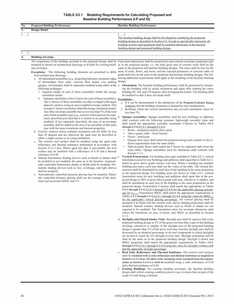
TABLE G3.1 Modeling Requirements for Calculating Proposed andBaseline Building Performance (I-P and SI)
No. Proposed Building Performance Baseline Building Performance
1. Design Model
[ . . . ] [ . . . ]The baseline building design shall be developed by modifying the proposedbuilding design as described in Section G3. Except as specifically instructed, allbuilding systems and equipment shall be modeled identically in the baselinebuilding design and proposed building design.
[ . . . ]
5. Building Envelope
All components of the building envelope in the proposed design shall bemodeled as shown on architectural drawings or as built for existing build-ing envelopes.
Exceptions: The following building elements are permitted to differfrom architectural drawings.a. All uninsulated assemblies (e.g., projecting balconies, perimeter edges
of intermediate floor stabs, concrete floor beams over parkinggarages, roof parapet) shall be separately modeled using either of thefollowing techniques:1. Separate model of each of these assemblies within the energy
simulation model.2. Separate calculation of the U-factor for each of these assemblies.
The U-factors of these assemblies are then averaged with largeradjacent surfaces using an area-weighted average method. Thisaverage U-factor is modeled within the energy simulation model.Any other envelope assembly that covers less than 5% of the totalarea of that assembly type (e.g., exterior walls) need not be sepa-rately described provided that it is similar to an assembly beingmodeled. If not separately described, the area of an envelopeassembly shall be added to the area of an assembly of that sametype with the same orientation and thermal properties.
b. Exterior surfaces whose azimuth orientation and tilt differ by lessthan 45 degrees and are otherwise the same may be described aseither a single surface or by using multipliers.
c. The exterior roof surface shall be modeled using the aged solarreflectance and thermal emittance determined in accordance withSection 5.5.3.1.2(a). Where aged test data is unavailable, the roofsurface may be modeled with a reflectance of 0.30 and a thermalemittance of 0.90.
d. Manual fenestration shading devices such as blinds or shades shallbe modeled or not modeled, the same as in the baseline. Automati-cally controlled fenestration shades or blinds shall be modeled. Per-manent shading devices such as fins, overhangs, and light shelvesshall be modeled.
e. Automatically controlled dynamic glazing may be modeled. Manu-ally controlled dynamic glazing shall use the average of the mini-mum and maximum SHGC and VT.
Equivalent dimensions shall be assumed for each exterior envelope component typeas in the proposed design; i.e., the total gross area of exterior walls shall be thesame in the proposed and baseline building designs. The same shall be true for theareas of roofs, floors, and doors, and the exposed perimeters of concrete slabs ongrade shall also be the same in the proposed and baseline building designs. The fol-lowing additional requirements shall apply to the modeling of the baseline buildingdesign:
a. Orientation. The baseline building performance shall be generated by simulat-ing the building with its actual orientation and again after rotating the entirebuilding 90, 180, and 270 degrees, then averaging the results. The building shallbe modeled so that it does not shade itself.
Exceptions:1. If it can be demonstrated to the satisfaction of the Program Evaluator Rating
Authority that the building orientation is dictated by site considerations.2. Buildings where the vertical fenestration area on each orientation varies by
less than 5%.
b. Opaque Assemblies. Opaque assemblies used for new buildings or additionsshall conform with the following common, lightweight assembly types andshall match the appropriate assembly maximum U-factors in Tables 5.5-1through 5.5-8 G3.4-1 through G3.4-8:• Roofs—Insulation entirely above deck• Above-grade walls—Steel-framed• Floors—Steel-joist• Opaque door types shall match the proposed design and conform to the U-
factor requirements from the same tables.• Slab-on-grade floors shall match the F-factor for unheated slabs from the
same tables. Opaque assemblies used for alterations shall conform withSection 5.1.3.
c. Vertical Fenestration. For building area types included in Table G3.3, verticalfenestration areas for new buildings and additions shall equal that in Table G3.3,based on gross above grade exterior wall area. Where a building has multiplebuilding area types, each type shall use the values in the table. The vertical fen-estration shall be distributed on each face of the building in the same proportionas the proposed design. For building areas not shown in Table G3.3, verticalfenestration areas for new buildings and additions shall equal that in the pro-posed design or 40% of gross above-grade wall area, whichever is smaller, andshall be distributed on each face of the building in the same proportions in theproposed design. Fenestration U-factors shall match the appropriate in Tables5.5-1 through 5.5-8 G3.4-1 through G3.4-8 for the applicable glazing percent-age for Ufixed. Fenestration SHGC shall match the appropriate requirements inTables 5.5-1 through 5.5-8 G3.4-1 through G3.4-8 using the value for SHGCallfor the applicable vertical glazing percentage. All vertical glazing shall beassumed to be flush with the exterior wall, and no shading projections shall bemodeled. Manual window shading devices such as blinds or shades are notrequired to be modeled. The fenestration areas for envelope alterations shallreflect the limitations on area, U-factor, and SHGC as described in Section5.1.3.
d. Skylights and Glazed Smoke Vents. Skylight area shall be equal to that in theproposed building design or 5% of the gross roof area that is part of the buildingenvelope, whichever is smaller. If the skylight area of the proposed buildingdesign is greater than 5% of the gross roof area, baseline skylight area shall bedecreased by an identical percentage in all roof components in which skylightsare located to reach the 5% skylight-to-roof ratio. Skylight orientation and tiltshall be the same as in the proposed building design. Skylight U-factor andSHGC properties shall match the appropriate requirements in Tables 5.5-1through 5.5-8 G3.4-1 through G3.4-8 using the value for skylights without curband the applicable skylight percentage.
e. Roof Solar Reflectance and Thermal Emittance. The exterior roof surfacesshall be modeled with a solar reflectance and thermal emittance as required inSection 5.5.3.1.2(a). All other roofs, including roofs exempted from the require-ments in Section 5.5.3.1.2, shall be modeled using a solar reflectance of 0.30and a thermal emittance of 0.90.
f. Existing Buildings. For existing building envelopes, the baseline buildingdesign shall reflect existing conditions prior to any revisions that are part of thescope of work being evaluated.
40 ANSI/ASHRAE/IES Addendum bm to ANSI/ASHRAE/IES Standard 90.1-2013
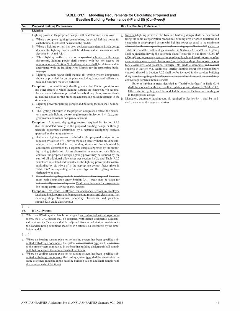
6. Lighting
Lighting power in the proposed design shall be determined as follows:
a. Where a complete lighting system exists, the actual lighting power foreach thermal block shall be used in the model.
b. Where a lighting system has been designed and submitted with designdocuments, lighting power shall be determined in accordance withSections 9.1.3 and 9.1.4.
c. Where lighting neither exists nor is specified submitted with designdocuments, lighting power shall comply with but not exceed therequirements of Section 9. Lighting power shall be determined inaccordance with the Building Area Method for the appropriate build-ing type.
d. Lighting system power shall include all lighting system componentsshown or provided for on the plans (including lamps and ballasts andtask and furniture mounted fixtures).
Exception: For multifamily dwelling units, hotel/motel guest rooms,and other spaces in which lighting systems are connected via recepta-cles and are not shown or provided for on building plans, assume identi-cal lighting power for the proposed and baseline building designs in thesimulations.
e. Lighting power for parking garages and building facades shall be mod-eled.
f. The lighting schedules in the proposed design shall reflect the manda-tory automatic lighting control requirements in Section 9.4.1(e.g., pro-grammable controls or occupancy sensors).
Exception: Automatic daylighting controls required by Section 9.4.1shall be modeled directly in the proposed building design or throughschedule adjustments determined by a separate daylighting analysisapproved by the rating authority
g. Automatic lighting controls included in the proposed design but notrequired by Section 9.4.1 may be modeled directly in the building sim-ulation or be modeled in the building simulation through scheduleadjustments determined by a separate analysis approved by the author-ity having jurisdiction. As an alternative to modeling such lightingcontrols, the proposed design lighting power may be reduced by thesum of all additional allowances per section 9.6.2c and Table 9.6.2which are calculated individually as the lighting power under controlmultiplied by cf, where cf is the appropriate control factor given inTable 9.6.2 corresponding to the space type and the lighting controlsdesigned to be used.
h. For automatic lighting controls in addition to those required for mini-mum code compliance under Section 9.4.1, credit may be taken forautomatically controlled systems Credit may be taken for programma-ble timing controls or occupancy sensors.
Exception: No credit is allowed for occupancy sensors in employeelunch and break rooms, conference/meeting rooms, and classrooms (notincluding shop classrooms, laboratory classrooms, and preschoolthrough 12th grade classrooms.)
a. Interior Llighting power in the baseline building design shall be determinedusing the same categorization procedure (building area or space function) andcategories as the proposed design with lighting power set equal to the maximumallowed for the corresponding method and category in Section 9.2 values inTable G3.7 and the methodology described in Section 9.6.1 and 9.6.2. Lightingshall be modeled having the automatic shutoff controls in buildings >5,000 ft2
(500 m2) and occupancy sensors in employee lunch and break rooms, confer-ence/meeting rooms, and classrooms (not including shop classrooms, labora-tory classrooms, and preschool through 12th grade classrooms) and manualcontrols in Section 9.4. Additional interior lighting power for nonmandatorycontrols allowed in Section 9.6.2 shall not be included in the baseline buildingdesign, as the lighting schedules used are understood to reflect the mandatorycontrol requirements in this standard.
Exterior lighting in areas identified as “Tradable Surfaces” in Table G3.6shall be modeled with the baseline lighting power shown in Table G3.6.Other exterior lighting shall be modeled the same in the baseline building asin the proposed design.
b. Mandatory automatic lighting controls required by Section 9.4.1 shall be mod-eled the same as the proposed design.
[ . . . ]
10. HVAC Systems
b. Where an HVAC system has been designed and submitted with design docu-ments, the HVAC model shall be consistent with design documents. Mechani-cal equipment efficiencies shall be adjusted from actual design conditions tothe standard rating conditions specified in Section 6.4.1 if required by the simu-lation model.
[ . . . ]
c. Where no heating system exists or no heating system has been specified sub-mitted with design documents, the system characteristics type shall be identicalto the same system as modeled in the baseline building design and shall complywith but not exceed the requirements of Section 6.
d. Where no cooling system exists or no cooling system has been specified sub-mitted with design documents, the cooling system type shall be identical to thesame as system modeled in the baseline building design and shall comply withthe requirements of Section 6.
TABLE G3.1 Modeling Requirements for Calculating Proposed andBaseline Building Performance (I-P and SI) (Continued)
No. Proposed Building Performance Baseline Building Performance
ANSI/ASHRAE/IES Addendum bm to ANSI/ASHRAE/IES Standard 90.1-2013 41
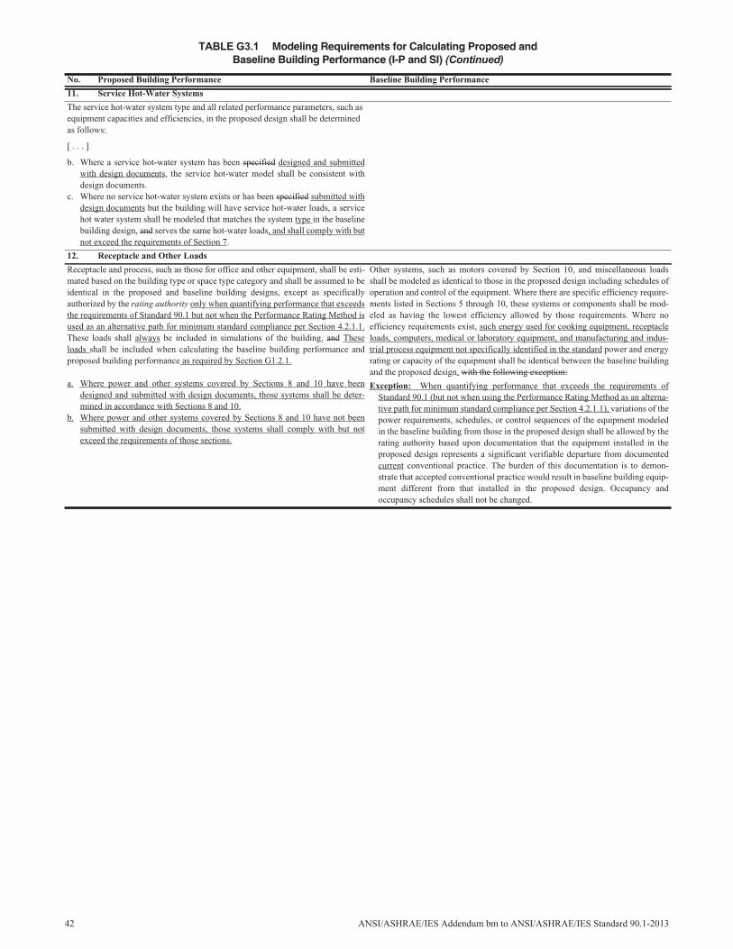
11. Service Hot-Water Systems
The service hot-water system type and all related performance parameters, such asequipment capacities and efficiencies, in the proposed design shall be determinedas follows:
[ . . . ]
b. Where a service hot-water system has been specified designed and submittedwith design documents, the service hot-water model shall be consistent withdesign documents.
c. Where no service hot-water system exists or has been specified submitted withdesign documents but the building will have service hot-water loads, a servicehot water system shall be modeled that matches the system type in the baselinebuilding design, and serves the same hot-water loads, and shall comply with butnot exceed the requirements of Section 7.
12. Receptacle and Other Loads
Receptacle and process, such as those for office and other equipment, shall be esti-mated based on the building type or space type category and shall be assumed to beidentical in the proposed and baseline building designs, except as specificallyauthorized by the rating authority only when quantifying performance that exceedsthe requirements of Standard 90.1 but not when the Performance Rating Method isused as an alternative path for minimum standard compliance per Section 4.2.1.1.These loads shall always be included in simulations of the building. and Theseloads shall be included when calculating the baseline building performance andproposed building performance as required by Section G1.2.1.
a. Where power and other systems covered by Sections 8 and 10 have beendesigned and submitted with design documents, those systems shall be deter-mined in accordance with Sections 8 and 10.
b. Where power and other systems covered by Sections 8 and 10 have not beensubmitted with design documents, those systems shall comply with but notexceed the requirements of those sections.
Other systems, such as motors covered by Section 10, and miscellaneous loadsshall be modeled as identical to those in the proposed design including schedules ofoperation and control of the equipment. Where there are specific efficiency require-ments listed in Sections 5 through 10, these systems or components shall be mod-eled as having the lowest efficiency allowed by those requirements. Where noefficiency requirements exist, such energy used for cooking equipment, receptacleloads, computers, medical or laboratory equipment, and manufacturing and indus-trial process equipment not specifically identified in the standard power and energyrating or capacity of the equipment shall be identical between the baseline buildingand the proposed design. with the following exception:
Exception: When quantifying performance that exceeds the requirements ofStandard 90.1 (but not when using the Performance Rating Method as an alterna-tive path for minimum standard compliance per Section 4.2.1.1), variations of thepower requirements, schedules, or control sequences of the equipment modeledin the baseline building from those in the proposed design shall be allowed by therating authority based upon documentation that the equipment installed in theproposed design represents a significant verifiable departure from documentedcurrent conventional practice. The burden of this documentation is to demon-strate that accepted conventional practice would result in baseline building equip-ment different from that installed in the proposed design. Occupancy andoccupancy schedules shall not be changed.
TABLE G3.1 Modeling Requirements for Calculating Proposed andBaseline Building Performance (I-P and SI) (Continued)
No. Proposed Building Performance Baseline Building Performance
42 ANSI/ASHRAE/IES Addendum bm to ANSI/ASHRAE/IES Standard 90.1-2013
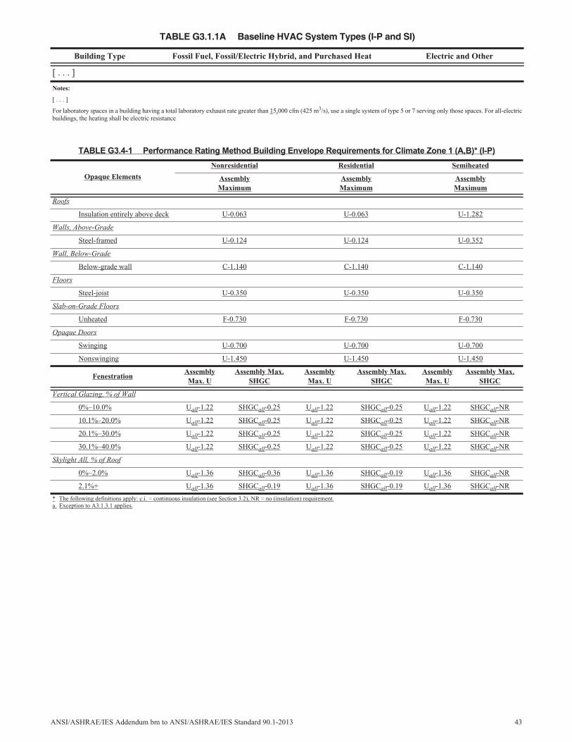
TABLE G3.1.1A Baseline HVAC System Types (I-P and SI)
Building Type Fossil Fuel, Fossil/Electric Hybrid, and Purchased Heat Electric and Other
[ . . . ]
Notes:
[ . . . ]
For laboratory spaces in a building having a total laboratory exhaust rate greater than 15,000 cfm (425 m3/s), use a single system of type 5 or 7 serving only those spaces. For all-electricbuildings, the heating shall be electric resistance
TABLE G3.4-1 Performance Rating Method Building Envelope Requirements for Climate Zone 1 (A,B)* (I-P)
Opaque Elements
Nonresidential Residential Semiheated
AssemblyMaximum
AssemblyMaximum
AssemblyMaximum
Roofs
Insulation entirely above deck U-0.063 U-0.063 U-1.282
Walls, Above-Grade
Steel-framed U-0.124 U-0.124 U-0.352
Wall, Below-Grade
Below-grade wall C-1.140 C-1.140 C-1.140
Floors
Steel-joist U-0.350 U-0.350 U-0.350
Slab-on-Grade Floors
Unheated F-0.730 F-0.730 F-0.730
Opaque Doors
Swinging U-0.700 U-0.700 U-0.700
Nonswinging U-1.450 U-1.450 U-1.450
FenestrationAssemblyMax. U
Assembly Max.SHGC
AssemblyMax. U
Assembly Max.SHGC
AssemblyMax. U
Assembly Max.SHGC
Vertical Glazing, % of Wall
0%–10.0% Uall-1.22 SHGCall-0.25 Uall-1.22 SHGCall-0.25 Uall-1.22 SHGCall-NR
10.1%–20.0% Uall-1.22 SHGCall-0.25 Uall-1.22 SHGCall-0.25 Uall-1.22 SHGCall-NR
20.1%–30.0% Uall-1.22 SHGCall-0.25 Uall-1.22 SHGCall-0.25 Uall-1.22 SHGCall-NR
30.1%–40.0% Uall-1.22 SHGCall-0.25 Uall-1.22 SHGCall-0.25 Uall-1.22 SHGCall-NR
Skylight All, % of Roof
0%–2.0% Uall-1.36 SHGCall-0.36 Uall-1.36 SHGCall-0.19 Uall-1.36 SHGCall-NR
2.1%+ Uall-1.36 SHGCall-0.19 Uall-1.36 SHGCall-0.19 Uall-1.36 SHGCall-NR
* The following definitions apply: c.i. = continuous insulation (see Section 3.2), NR = no (insulation) requirement.a. Exception to A3.1.3.1 applies.
ANSI/ASHRAE/IES Addendum bm to ANSI/ASHRAE/IES Standard 90.1-2013 43
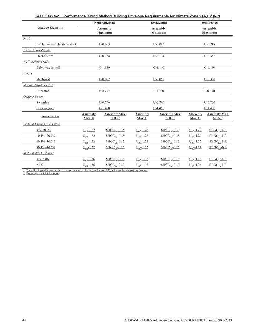
TABLE G3.4-2 Performance Rating Method Building Envelope Requirements for Climate Zone 2 (A,B)* (I-P)
Opaque Elements
Nonresidential Residential Semiheated
AssemblyMaximum
AssemblyMaximum
AssemblyMaximum
Roofs
Insulation entirely above deck U-0.063 U-0.063 U-0.218
Walls, Above-Grade
Steel-framed U-0.124 U-0.124 U-0.352
Wall, Below-Grade
Below-grade wall C-1.140 C-1.140 C-1.140
Floors
Steel-joist U-0.052 U-0.052 U-0.350
Slab-on-Grade Floors
Unheated F-0.730 F-0.730 F-0.730
Opaque Doors
Swinging U-0.700 U-0.700 U-0.700
Nonswinging U-1.450 U-1.450 U-1.450
FenestrationAssemblyMax. U
Assembly Max.SHGC
AssemblyMax. U
Assembly Max.SHGC
AssemblyMax. U
Assembly Max.SHGC
Vertical Glazing, % of Wall
0%–10.0% Uall-1.22 SHGCall-0.25 Uall-1.22 SHGCall-0.39 Uall-1.22 SHGCall-NR
10.1%–20.0% Uall-1.22 SHGCall-0.25 Uall-1.22 SHGCall-0.25 Uall-1.22 SHGCall-NR
20.1%–30.0% Uall-1.22 SHGCall-0.25 Uall-1.22 SHGCall-0.25 Uall-1.22 SHGCall-NR
30.1%–40.0% Uall-1.22 SHGCall-0.25 Uall-1.22 SHGCall-0.25 Uall-1.22 SHGCall-NR
Skylight All, % of Roof
0%–2.0% Uall-1.36 SHGCall-0.36 Uall-1.36 SHGCall-0.19 Uall-1.36 SHGCall-NR
2.1%+ Uall-1.36 SHGCall-0.19 Uall-1.36 SHGCall-0.19 Uall-1.36 SHGCall-NR
* The following definitions apply: c.i. = continuous insulation (see Section 3.2), NR = no (insulation) requirement.a. Exception to A3.1.3.1 applies.
44 ANSI/ASHRAE/IES Addendum bm to ANSI/ASHRAE/IES Standard 90.1-2013
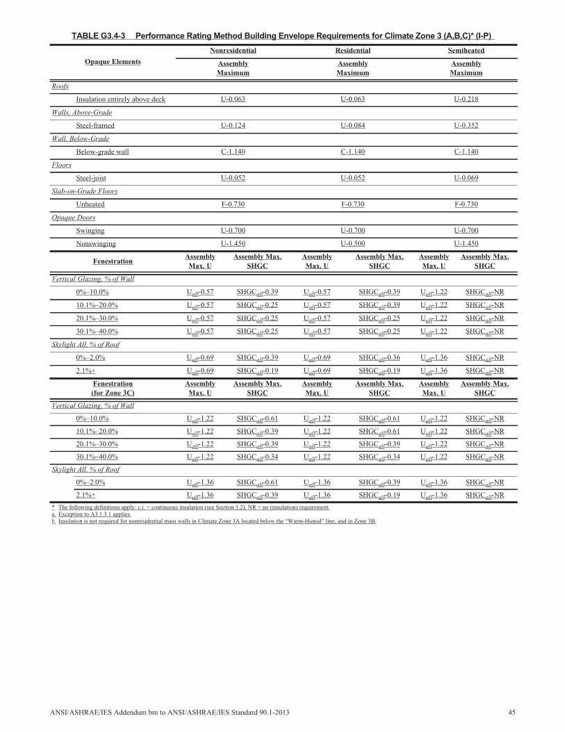
TABLE G3.4-3 Performance Rating Method Building Envelope Requirements for Climate Zone 3 (A,B,C)* (I-P)
Opaque Elements
Nonresidential Residential Semiheated
AssemblyMaximum
AssemblyMaximum
AssemblyMaximum
Roofs
Insulation entirely above deck U-0.063 U-0.063 U-0.218
Walls, Above-Grade
Steel-framed U-0.124 U-0.084 U-0.352
Wall, Below-Grade
Below-grade wall C-1.140 C-1.140 C-1.140
Floors
Steel-joist U-0.052 U-0.052 U-0.069
Slab-on-Grade Floors
Unheated F-0.730 F-0.730 F-0.730
Opaque Doors
Swinging U-0.700 U-0.700 U-0.700
Nonswinging U-1.450 U-0.500 U-1.450
FenestrationAssemblyMax. U
Assembly Max.SHGC
AssemblyMax. U
Assembly Max.SHGC
AssemblyMax. U
Assembly Max.SHGC
Vertical Glazing, % of Wall
0%–10.0% Uall-0.57 SHGCall-0.39 Uall-0.57 SHGCall-0.39 Uall-1.22 SHGCall-NR
10.1%–20.0% Uall-0.57 SHGCall-0.25 Uall-0.57 SHGCall-0.39 Uall-1.22 SHGCall-NR
20.1%–30.0% Uall-0.57 SHGCall-0.25 Uall-0.57 SHGCall-0.25 Uall-1.22 SHGCall-NR
30.1%–40.0% Uall-0.57 SHGCall-0.25 Uall-0.57 SHGCall-0.25 Uall-1.22 SHGCall-NR
Skylight All, % of Roof
0%–2.0% Uall-0.69 SHGCall-0.39 Uall-0.69 SHGCall-0.36 Uall-1.36 SHGCall-NR
2.1%+ Uall-0.69 SHGCall-0.19 Uall-0.69 SHGCall-0.19 Uall-1.36 SHGCall-NR
Fenestration(for Zone 3C)
AssemblyMax. U
Assembly Max.SHGC
AssemblyMax. U
Assembly Max.SHGC
AssemblyMax. U
Assembly Max.SHGC
Vertical Glazing, % of Wall
0%–10.0% Uall-1.22 SHGCall-0.61 Uall-1.22 SHGCall-0.61 Uall-1.22 SHGCall-NR
10.1%–20.0% Uall-1.22 SHGCall-0.39 Uall-1.22 SHGCall-0.61 Uall-1.22 SHGCall-NR
20.1%–30.0% Uall-1.22 SHGCall-0.39 Uall-1.22 SHGCall-0.39 Uall-1.22 SHGCall-NR
30.1%–40.0% Uall-1.22 SHGCall-0.34 Uall-1.22 SHGCall-0.34 Uall-1.22 SHGCall-NR
Skylight All, % of Roof
0%–2.0% Uall-1.36 SHGCall-0.61 Uall-1.36 SHGCall-0.39 Uall-1.36 SHGCall-NR
2.1%+ Uall-1.36 SHGCall-0.39 Uall-1.36 SHGCall-0.19 Uall-1.36 SHGCall-NR
* The following definitions apply: c.i. = continuous insulation (see Section 3.2), NR = no (insulation) requirement.a. Exception to A3.1.3.1 applies.b. Insulation is not required for nonresidential mass walls in Climate Zone 3A located below the “Warm-Humid” line, and in Zone 3B.
ANSI/ASHRAE/IES Addendum bm to ANSI/ASHRAE/IES Standard 90.1-2013 45
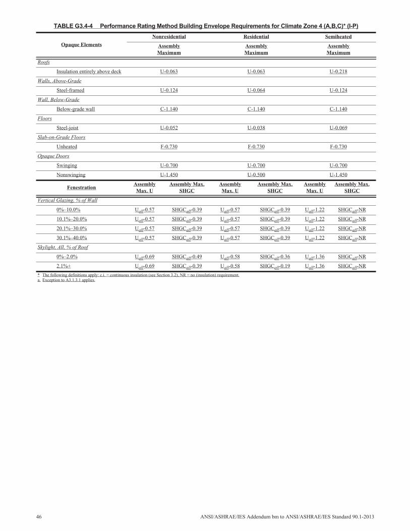
TABLE G3.4-4 Performance Rating Method Building Envelope Requirements for Climate Zone 4 (A,B,C)* (I-P)
Opaque Elements
Nonresidential Residential Semiheated
AssemblyMaximum
AssemblyMaximum
AssemblyMaximum
Roofs
Insulation entirely above deck U-0.063 U-0.063 U-0.218
Walls, Above-Grade
Steel-framed U-0.124 U-0.064 U-0.124
Wall, Below-Grade
Below-grade wall C-1.140 C-1.140 C-1.140
Floors
Steel-joist U-0.052 U-0.038 U-0.069
Slab-on-Grade Floors
Unheated F-0.730 F-0.730 F-0.730
Opaque Doors
Swinging U-0.700 U-0.700 U-0.700
Nonswinging U-1.450 U-0.500 U-1.450
FenestrationAssemblyMax. U
Assembly Max.SHGC
AssemblyMax. U
Assembly Max.SHGC
AssemblyMax. U
Assembly Max.SHGC
Vertical Glazing, % of Wall
0%–10.0% Uall-0.57 SHGCall-0.39 Uall-0.57 SHGCall-0.39 Uall-1.22 SHGCall-NR
10.1%–20.0% Uall-0.57 SHGCall-0.39 Uall-0.57 SHGCall-0.39 Uall-1.22 SHGCall-NR
20.1%–30.0% Uall-0.57 SHGCall-0.39 Uall-0.57 SHGCall-0.39 Uall-1.22 SHGCall-NR
30.1%–40.0% Uall-0.57 SHGCall-0.39 Uall-0.57 SHGCall-0.39 Uall-1.22 SHGCall-NR
Skylight, All, % of Roof
0%–2.0% Uall-0.69 SHGCall-0.49 Uall-0.58 SHGCall-0.36 Uall-1.36 SHGCall-NR
2.1%+ Uall-0.69 SHGCall-0.39 Uall-0.58 SHGCall-0.19 Uall-1.36 SHGCall-NR
* The following definitions apply: c.i. = continuous insulation (see Section 3.2), NR = no (insulation) requirement.a. Exception to A3.1.3.1 applies.
46 ANSI/ASHRAE/IES Addendum bm to ANSI/ASHRAE/IES Standard 90.1-2013

TABLE G3.4-5 Performance Rating Method Building Envelope Requirements for Climate Zone 5 (A,B,C)* (I-P)
Opaque Elements
Nonresidential Residential Semiheated
AssemblyMaximum
AssemblyMaximum
AssemblyMaximum
Roofs
Insulation entirely above deck U-0.063 U-0.063 U-0.173
Walls, Above-Grade
Steel-framed U-0.084 U-0.064 U-0.124
Wall, Below-Grade
Below-grade wall C-1.140 C-1.140 C-1.140
Floors
Steel-joist U-0.052 U-0.038 U-0.069
Slab-on-Grade Floors
Unheated F-0.730 F-0.730 F-0.730
Opaque Doors
Swinging U-0.700 U-0.700 U-0.700
Nonswinging U-1.450 U-0.500 U-1.450
FenestrationAssemblyMax. U
Assembly Max.SHGC
AssemblyMax. U
Assembly Max.SHGC
AssemblyMax. U
Assembly Max.SHGC
Vertical Glazing, % of Wall
0%–10.0% Uall-0.57 SHGCall-0.49 Uall-0.57 SHGCall-0.49 Uall-1.22 SHGCall-NR
10.1%–20.0% Uall-0.57 SHGCall-0.39 Uall-0.57 SHGCall-0.39 Uall-1.22 SHGCall-NR
20.1%–30.0% Uall-0.57 SHGCall-0.39 Uall-0.57 SHGCall-0.39 Uall-1.22 SHGCall-NR
30.1%–40.0% Uall-0.57 SHGCall-0.39 Uall-0.57 SHGCall-0.39 Uall-1.22 SHGCall-NR
Skylight, All, % of Roof
0%–2.0% Uall-0.69 SHGCall-0.49 Uall-0.69 SHGCall-0.49 Uall-1.36 SHGCall-NR
2.1%+ Uall-0.69 SHGCall-0.39 Uall-0.69 SHGCall-0.39 Uall-1.36 SHGCall-NR
* The following definitions apply: c.i. = continuous insulation (see Section 3.2), NR = no (insulation) requirement.
ANSI/ASHRAE/IES Addendum bm to ANSI/ASHRAE/IES Standard 90.1-2013 47
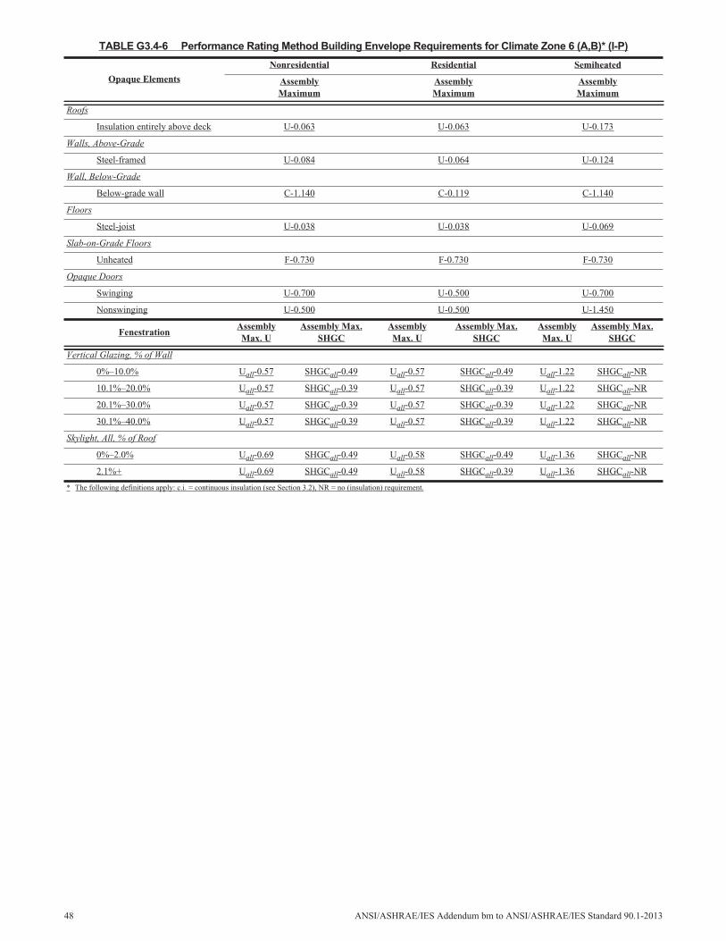
TABLE G3.4-6 Performance Rating Method Building Envelope Requirements for Climate Zone 6 (A,B)* (I-P)
Opaque Elements
Nonresidential Residential Semiheated
AssemblyMaximum
AssemblyMaximum
AssemblyMaximum
Roofs
Insulation entirely above deck U-0.063 U-0.063 U-0.173
Walls, Above-Grade
Steel-framed U-0.084 U-0.064 U-0.124
Wall, Below-Grade
Below-grade wall C-1.140 C-0.119 C-1.140
Floors
Steel-joist U-0.038 U-0.038 U-0.069
Slab-on-Grade Floors
Unheated F-0.730 F-0.730 F-0.730
Opaque Doors
Swinging U-0.700 U-0.500 U-0.700
Nonswinging U-0.500 U-0.500 U-1.450
FenestrationAssemblyMax. U
Assembly Max.SHGC
AssemblyMax. U
Assembly Max.SHGC
AssemblyMax. U
Assembly Max.SHGC
Vertical Glazing, % of Wall
0%–10.0% Uall-0.57 SHGCall-0.49 Uall-0.57 SHGCall-0.49 Uall-1.22 SHGCall-NR
10.1%–20.0% Uall-0.57 SHGCall-0.39 Uall-0.57 SHGCall-0.39 Uall-1.22 SHGCall-NR
20.1%–30.0% Uall-0.57 SHGCall-0.39 Uall-0.57 SHGCall-0.39 Uall-1.22 SHGCall-NR
30.1%–40.0% Uall-0.57 SHGCall-0.39 Uall-0.57 SHGCall-0.39 Uall-1.22 SHGCall-NR
Skylight, All, % of Roof
0%–2.0% Uall-0.69 SHGCall-0.49 Uall-0.58 SHGCall-0.49 Uall-1.36 SHGCall-NR
2.1%+ Uall-0.69 SHGCall-0.49 Uall-0.58 SHGCall-0.39 Uall-1.36 SHGCall-NR
* The following definitions apply: c.i. = continuous insulation (see Section 3.2), NR = no (insulation) requirement.
48 ANSI/ASHRAE/IES Addendum bm to ANSI/ASHRAE/IES Standard 90.1-2013
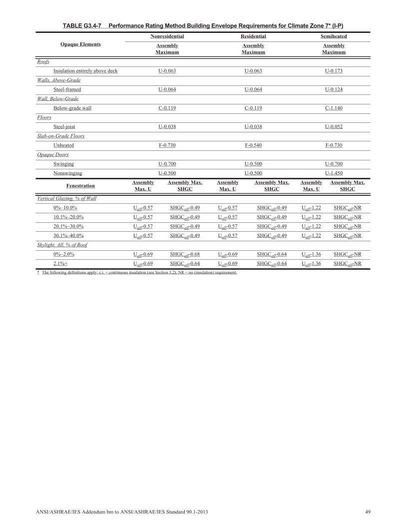
TABLE G3.4-7 Performance Rating Method Building Envelope Requirements for Climate Zone 7* (I-P)
Opaque Elements
Nonresidential Residential Semiheated
AssemblyMaximum
AssemblyMaximum
AssemblyMaximum
Roofs
Insulation entirely above deck U-0.063 U-0.063 U-0.173
Walls, Above-Grade
Steel-framed U-0.064 U-0.064 U-0.124
Wall, Below-Grade
Below-grade wall C-0.119 C-0.119 C-1.140
Floors
Steel-joist U-0.038 U-0.038 U-0.052
Slab-on-Grade Floors
Unheated F-0.730 F-0.540 F-0.730
Opaque Doors
Swinging U-0.700 U-0.500 U-0.700
Nonswinging U-0.500 U-0.500 U-1.450
FenestrationAssemblyMax. U
Assembly Max.SHGC
AssemblyMax. U
Assembly Max.SHGC
AssemblyMax. U
Assembly Max.SHGC
Vertical Glazing, % of Wall
0%–10.0% Uall-0.57 SHGCall-0.49 Uall-0.57 SHGCall-0.49 Uall-1.22 SHGCall-NR
10.1%–20.0% Uall-0.57 SHGCall-0.49 Uall-0.57 SHGCall-0.49 Uall-1.22 SHGCall-NR
20.1%–30.0% Uall-0.57 SHGCall-0.49 Uall-0.57 SHGCall-0.49 Uall-1.22 SHGCall-NR
30.1%–40.0% Uall-0.57 SHGCall-0.49 Uall-0.57 SHGCall-0.49 Uall-1.22 SHGCall-NR
Skylight, All, % of Roof
0%–2.0% Uall-0.69 SHGCall-0.68 Uall-0.69 SHGCall-0.64 Uall-1.36 SHGCall-NR
2.1%+ Uall-0.69 SHGCall-0.64 Uall-0.69 SHGCall-0.64 Uall-1.36 SHGCall-NR
* The following definitions apply: c.i. = continuous insulation (see Section 3.2), NR = no (insulation) requirement.
ANSI/ASHRAE/IES Addendum bm to ANSI/ASHRAE/IES Standard 90.1-2013 49
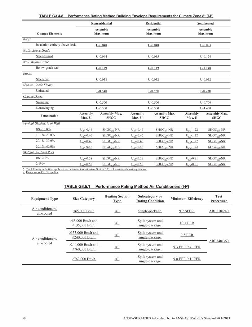
TABLE G3.4-8 Performance Rating Method Building Envelope Requirements for Climate Zone 8* (I-P)
Opaque Elements
Nonresidential Residential Semiheated
AssemblyMaximum
AssemblyMaximum
AssemblyMaximum
Roofs
Insulation entirely above deck U-0.048 U-0.048 U-0.093
Walls, Above-Grade
Steel-framed U-0.064 U-0.055 U-0.124
Wall, Below-Grade
Below-grade wall C-0.119 C-0.119 C-1.140
Floors
Steel-joist U-0.038 U-0.032 U-0.052
Slab-on-Grade Floors
Unheated F-0.540 F-0.520 F-0.730
Opaque Doors
Swinging U-0.500 U-0.500 U-0.700
Nonswinging U-0.500 U-0.500 U-1.450
FenestrationAssemblyMax. U
Assembly Max.SHGC
AssemblyMax. U
Assembly Max.SHGC
AssemblyMax. U
Assembly Max.SHGC
Vertical Glazing, % of Wall
0%–10.0% Uall-0.46 SHGCall-NR Uall-0.46 SHGCall-NR Uall-1.22 SHGCall-NR
10.1%–20.0% Uall-0.46 SHGCall-NR Uall-0.46 SHGCall-NR Uall-1.22 SHGCall-NR
20.1%–30.0% Uall-0.46 SHGCall-NR Uall-0.46 SHGCall-NR Uall-1.22 SHGCall-NR
30.1%–40.0% Uall-0.46 SHGCall-NR Uall-0.46 SHGCall-NR Uall-1.22 SHGCall-NR
Skylight, All, % of Roof
0%–2.0% Uall-0.58 SHGCall-NR Uall-0.58 SHGCall-NR Uall-0.81 SHGCall-NR
2.1%+ Uall-0.58 SHGCall-NR Uall-0.58 SHGCall-NR Uall-0.81 SHGCall-NR
* The following definitions apply: c.i. = continuous insulation (see Section 3.2), NR = no (insulation) requirement.a. Exception to A3.1.3.1 applies.
TABLE G3.5.1 Performance Rating Method Air Conditioners (I-P)
Equipment Type Size CategoryHeating Section
TypeSubcategory or
Rating ConditionMinimum Efficiency
TestProcedure
Air conditioners,air-cooled
<65,000 Btu/h All Single-package 9.7 SEER ARI 210/240
Air conditioners,air-cooled
65,000 Btu/h and<135,000 Btu/h
AllSplit-system andsingle-package
10.1 EER
ARI 340/360
135,000 Btu/h and<240,000 Btu/h
AllSplit-system andsingle-package
9.5 EER
240,000 Btu/h and<760,000 Btu/h
AllSplit-system andsingle-package
9.3 EER 9.4 IEER
760,000 Btu/h AllSplit-system andsingle-package
9.0 EER 9.1 IEER
50 ANSI/ASHRAE/IES Addendum bm to ANSI/ASHRAE/IES Standard 90.1-2013
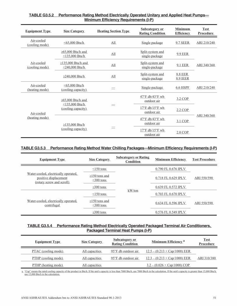
TABLE G3.5.2 Performance Rating Method Electrically Operated Unitary and Applied Heat Pumps—Minimum Efficiency Requirements (I-P)
Equipment Type Size Category Heating Section TypeSubcategory or
Rating ConditionMinimumEfficiency
TestProcedure
Air-cooled(cooling mode)
<65,000 Btu/h All Single package 9.7 SEER ARI 210/240
Air-cooled(cooling mode)
65,000 Btu/h and<135,000 Btu/h
AllSplit-system andsingle-package
9.9 EER
ARI 340/360135,000 Btu/h and
<240,000 Btu/hAll
Split-system andsingle-package
9.1 EER
240,000 Btu/h AllSplit-system andsingle-package
8.8 EER8.9 IEER
Air-cooled(heating mode)
<65,000 Btu/h(cooling capacity)
— Single-package 6.6 HSPF ARI 210/240
Air-cooled(heating mode)
65,000 Btu/h and<135,000 Btu/h
(cooling capacity)—
47°F db/43°F wboutdoor air
3.2 COP
ARI 340/360
17°F db/15°F wboutdoor air
2.2 COP
135,000 Btu/h(cooling capacity)
—
47°F db/43°F wboutdoor air
3.1 COP
17°F db/15°F wboutdoor air
2.0 COP
TABLE G3.5.3 Performance Rating Method Water Chilling Packages—Minimum Efficiency Requirements (I-P)
Equipment Type Size CategorySubcategory or Rating
ConditionMinimum Efficiency Test Procedure
Water-cooled, electrically operated,positive displacement
(rotary screw and scroll)
<150 tons
kW/ton
0.790 FL 0.676 IPLV
ARI 550/590150 tons and
<300 tons0.718 FL 0.629 IPLV
300 tons 0.639 FL 0.572 IPLV
Water-cooled, electrically operated,centrifugal
<150 tons 0.703 FL 0.670 IPLV
ARI 550/590150 tons and
<300 tons0.634 FL 0.596 IPLV
300 tons 0.576 FL 0.549 IPLV
TABLE G3.5.4 Performance Rating Method Electrically Operated Packaged Terminal Air Conditioners,Packaged Terminal Heat Pumps (I-P)
Equipment Type Size CategorySubcategory or
Rating ConditionMinimum Efficiency a Test
Procedure
PTAC (cooling mode) All capacities 95°F db outdoor air 12.5 – (0.213 × Cap/1000) EER
ARI 310/380PTHP (cooling mode) All capacities 95°F db outdoor air 12.3 – (0.213 × Cap/1000) EER
PTHP (heating mode) All capacities 3.2 – (0.026 × Cap/1000) COP
a. “Cap” means the rated cooling capacity of the product in Btu/h. If the unit's capacity is less than 7000 Btu/h, use 7000 Btu/h in the calculation. If the unit's capacity is greater than 15,000 Btu/h,use 15,000 Btu/h in the calculation.
ANSI/ASHRAE/IES Addendum bm to ANSI/ASHRAE/IES Standard 90.1-2013 51
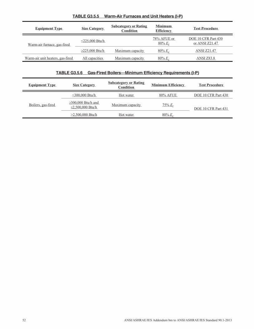
TABLE G3.5.5 Warm-Air Furnaces and Unit Heaters (I-P)
Equipment Type Size CategorySubcategory or Rating
ConditionMinimumEfficiency
Test Procedure
Warm-air furnace, gas-fired<225,000 Btu/h
78% AFUE or80% Et
DOE 10 CFR Part 430or ANSI Z21.47
225,000 Btu/h Maximum capacity 80% Ec ANSI Z21.47
Warm-air unit heaters, gas-fired All capacities Maximum capacity 80% Ec ANSI Z83.8
TABLE G3.5.6 Gas-Fired Boilers—Minimum Efficiency Requirements (I-P)
Equipment Type Size CategorySubcategory or Rating
ConditionMinimum Efficiency Test Procedure
Boilers, gas-fired
<300,000 Btu/h Hot water 80% AFUE DOE 10 CFR Part 430
300,000 Btu/h and2,500,000 Btu/h
Maximum capacity 75% EtDOE 10 CFR Part 431
>2,500,000 Btu/h Hot water 80% Ec
52 ANSI/ASHRAE/IES Addendum bm to ANSI/ASHRAE/IES Standard 90.1-2013
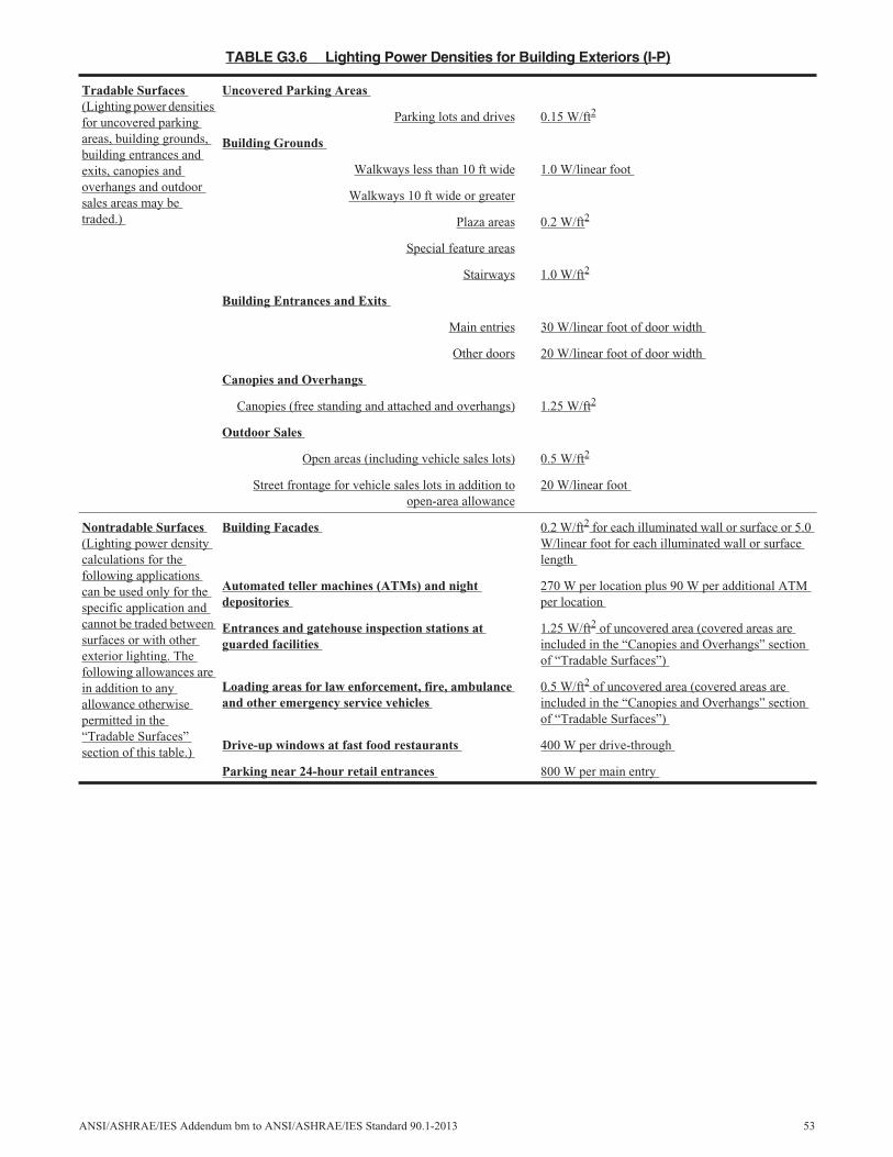
TABLE G3.6 Lighting Power Densities for Building Exteriors (I-P)
Tradable Surfaces(Lighting power densitiesfor uncovered parkingareas, building grounds,building entrances andexits, canopies andoverhangs and outdoorsales areas may betraded.)
Uncovered Parking Areas
Parking lots and drives 0.15 W/ft2
Building Grounds
Walkways less than 10 ft wide 1.0 W/linear foot
Walkways 10 ft wide or greater
Plaza areas 0.2 W/ft2
Special feature areas
Stairways 1.0 W/ft2
Building Entrances and Exits
Main entries 30 W/linear foot of door width
Other doors 20 W/linear foot of door width
Canopies and Overhangs
Canopies (free standing and attached and overhangs) 1.25 W/ft2
Outdoor Sales
Open areas (including vehicle sales lots) 0.5 W/ft2
Street frontage for vehicle sales lots in addition toopen-area allowance
20 W/linear foot
Nontradable Surfaces(Lighting power densitycalculations for thefollowing applicationscan be used only for thespecific application andcannot be traded betweensurfaces or with otherexterior lighting. Thefollowing allowances arein addition to anyallowance otherwisepermitted in the“Tradable Surfaces”section of this table.)
Building Facades 0.2 W/ft2 for each illuminated wall or surface or 5.0W/linear foot for each illuminated wall or surfacelength
Automated teller machines (ATMs) and nightdepositories
270 W per location plus 90 W per additional ATMper location
Entrances and gatehouse inspection stations atguarded facilities
1.25 W/ft2 of uncovered area (covered areas areincluded in the “Canopies and Overhangs” sectionof “Tradable Surfaces”)
Loading areas for law enforcement, fire, ambulanceand other emergency service vehicles
0.5 W/ft2 of uncovered area (covered areas areincluded in the “Canopies and Overhangs” sectionof “Tradable Surfaces”)
Drive-up windows at fast food restaurants 400 W per drive-through
Parking near 24-hour retail entrances 800 W per main entry
ANSI/ASHRAE/IES Addendum bm to ANSI/ASHRAE/IES Standard 90.1-2013 53
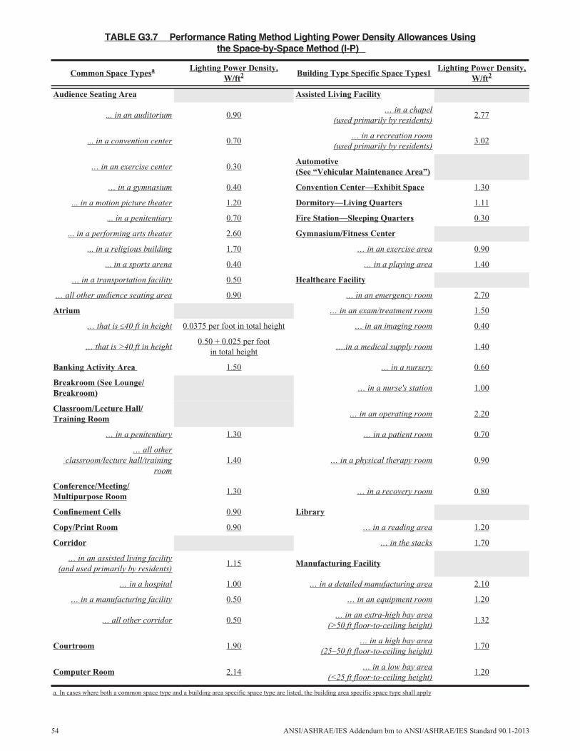
TABLE G3.7 Performance Rating Method Lighting Power Density Allowances Usingthe Space-by-Space Method (I-P)
Common Space Typesa Lighting Power Density,W/ft2 Building Type Specific Space Types1
Lighting Power Density,W/ft2
Audience Seating Area Assisted Living Facility
... in an auditorium 0.90… in a chapel
(used primarily by residents)2.77
... in a convention center 0.70… in a recreation room
(used primarily by residents)3.02
… in an exercise center 0.30Automotive(See “Vehicular Maintenance Area”)
… in a gymnasium 0.40 Convention Center—Exhibit Space 1.30
... in a motion picture theater 1.20 Dormitory—Living Quarters 1.11
... in a penitentiary 0.70 Fire Station—Sleeping Quarters 0.30
... in a performing arts theater 2.60 Gymnasium/Fitness Center
... in a religious building 1.70 … in an exercise area 0.90
... in a sports arena 0.40 … in a playing area 1.40
… in a transportation facility 0.50 Healthcare Facility
… all other audience seating area 0.90 … in an emergency room 2.70
Atrium … in an exam/treatment room 1.50
… that is 40 ft in height 0.0375 per foot in total height … in an imaging room 0.40
… that is >40 ft in height0.50 + 0.025 per foot
in total height….in a medical supply room 1.40
Banking Activity Area 1.50 … in a nursery 0.60
Breakroom (See Lounge/Breakroom)
… in a nurse's station 1.00
Classroom/Lecture Hall/Training Room
… in an operating room 2.20
… in a penitentiary 1.30 … in a patient room 0.70
… all otherclassroom/lecture hall/training
room1.40 … in a physical therapy room 0.90
Conference/Meeting/Multipurpose Room
1.30 … in a recovery room 0.80
Confinement Cells 0.90 Library
Copy/Print Room 0.90 … in a reading area 1.20
Corridor … in the stacks 1.70
… in an assisted living facility(and used primarily by residents)
1.15 Manufacturing Facility
… in a hospital 1.00 … in a detailed manufacturing area 2.10
… in a manufacturing facility 0.50 … in an equipment room 1.20
… all other corridor 0.50… in an extra-high bay area
(>50 ft floor-to-ceiling height)1.32
Courtroom 1.90… in a high bay area
(25–50 ft floor-to-ceiling height)1.70
Computer Room 2.14… in a low bay area
(<25 ft floor-to-ceiling height)1.20
a. In cases where both a common space type and a building area specific space type are listed, the building area specific space type shall apply
54 ANSI/ASHRAE/IES Addendum bm to ANSI/ASHRAE/IES Standard 90.1-2013
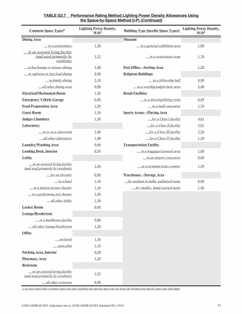
Dining Area Museum
… in a penitentiary 1.30 … in a general exhibition area 1.00
… in an assisted living facility(and used primarily by
residents)3.32 … in a restoration room 1.70
… in bar/lounge or leisure dining 1.40 Post Office—Sorting Area 1.20
… in cafeteria or fast food dining 0.90 Religious Buildings
… in family dining 2.10 … in a fellowship hall 0.90
… all other dining area 0.90 … in a worship/pulpit/choir area 2.40
Electrical/Mechanical Room 1.50 Retail Facilities
Emergency Vehicle Garage 0.80 … in a dressing/fitting room 0.89
Food Preparation Area 1.20 … in a mall concourse 1.70
Guest Room 1.10 Sports Arena—Playing Area
Judges Chambers 1.30 … for a Class I facility 4.61
Laboratory … for a Class II facility 3.01
… in or as a classroom 1.40 … for a Class III facility 2.26
… all other laboratory 1.40 … for a Class IV facility 1.50
Laundry/Washing Area 0.60 Transportation Facility
Loading Dock, Interior 0.59 … in a baggage/carousel area 1.00
Lobby … in an airport concourse 0.60
… in an assisted living facility(and used primarily by residents)
2.26 … at a terminal ticket counter 1.50
… for an elevator 0.80 Warehouse—Storage Area
… in a hotel 1.10 …for medium to bulky, palletized items 0.90
… in a motion picture theater 1.10 … for smaller, hand-carried items 1.40
… in a performing arts theater 3.30
… all other lobby 1.30
Locker Room 0.60
Lounge/Breakroom
… in a healthcare facility 0.80
… all other lounge/breakroom 1.20
Office
… enclosed 1.10
… open plan 1.10
Parking Area, Interior 0.20
Pharmacy Area 1.20
Restroom
… in an assisted living facility(and used primarily by residents)
1.52
… all other restroom 0.90
TABLE G3.7 Performance Rating Method Lighting Power Density Allowances Usingthe Space-by-Space Method (I-P) (Continued)
Common Space Typesa Lighting Power Density,W/ft2 Building Type Specific Space Types1
Lighting Power Density,W/ft2
a. In cases where both a common space type and a building area specific space type are listed, the building area specific space type shall apply
ANSI/ASHRAE/IES Addendum bm to ANSI/ASHRAE/IES Standard 90.1-2013 55
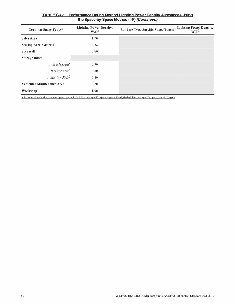
Sales Area 1.70
Seating Area, General 0.68
Stairwell 0.60
Storage Room
… in a hospital 0.90
… that is 50 ft2 0.80
… that is <50 ft2 0.80
Vehicular Maintenance Area 0.70
Workshop 1.90
TABLE G3.7 Performance Rating Method Lighting Power Density Allowances Usingthe Space-by-Space Method (I-P) (Continued)
Common Space Typesa Lighting Power Density,W/ft2 Building Type Specific Space Types1
Lighting Power Density,W/ft2
a. In cases where both a common space type and a building area specific space type are listed, the building area specific space type shall apply
56 ANSI/ASHRAE/IES Addendum bm to ANSI/ASHRAE/IES Standard 90.1-2013
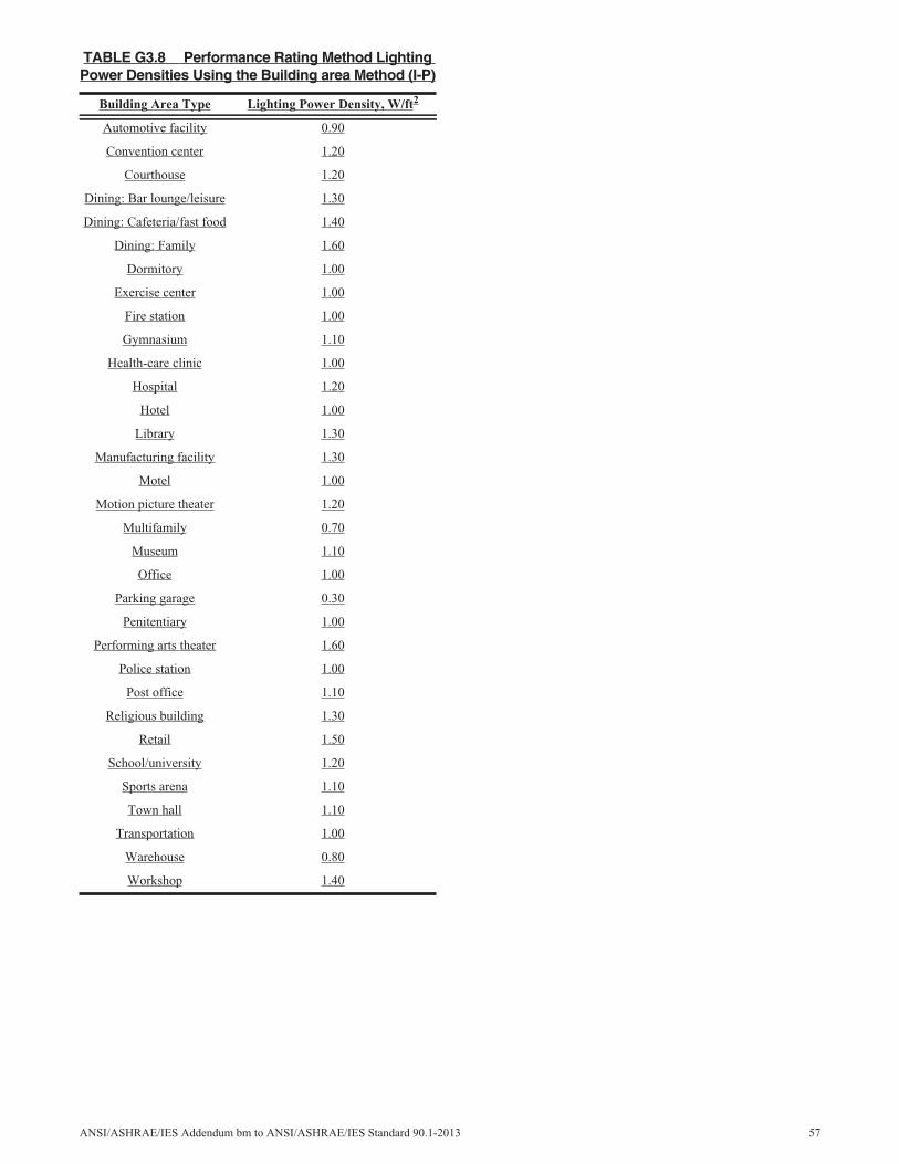
TABLE G3.8 Performance Rating Method LightingPower Densities Using the Building area Method (I-P)
Building Area Type Lighting Power Density, W/ft2
Automotive facility 0.90
Convention center 1.20
Courthouse 1.20
Dining: Bar lounge/leisure 1.30
Dining: Cafeteria/fast food 1.40
Dining: Family 1.60
Dormitory 1.00
Exercise center 1.00
Fire station 1.00
Gymnasium 1.10
Health-care clinic 1.00
Hospital 1.20
Hotel 1.00
Library 1.30
Manufacturing facility 1.30
Motel 1.00
Motion picture theater 1.20
Multifamily 0.70
Museum 1.10
Office 1.00
Parking garage 0.30
Penitentiary 1.00
Performing arts theater 1.60
Police station 1.00
Post office 1.10
Religious building 1.30
Retail 1.50
School/university 1.20
Sports arena 1.10
Town hall 1.10
Transportation 1.00
Warehouse 0.80
Workshop 1.40
ANSI/ASHRAE/IES Addendum bm to ANSI/ASHRAE/IES Standard 90.1-2013 57

TABLE G3.4-1 Performance Rating Method Building Envelope Requirements for Climate Zone 1 (A,B)* (SI)
Opaque Elements
Nonresidential Residential Semiheated
AssemblyMaximum
AssemblyMaximum
AssemblyMaximum
Roofs
Insulation entirely above deck U-0.360 U-0.360 U-7.280
Walls, Above-Grade
Steel-framed U-0.705 U-0.705 U-1.998
Wall, Below-Grade
Below-grade wall C-6.473 C-6.473 C-6.473
Floors
Steel-joist U-1.986 U-1.986 U-1.986
Slab-on-Grade Floors
Unheated F-1.264 F-1.264 F-1.264
Opaque Doors
Swinging U-3.975 U-3.975 U-3.975
Nonswinging U-8.233 U-8.233 U-8.233
FenestrationAssemblyMax. U
Assembly Max.SHGC
AssemblyMax. U
Assembly Max.SHGC
AssemblyMax. U
Assembly Max.SHGC
Vertical Glazing, % of Wall
0%–10.0% Uall-6.93 SHGCall-0.25 Uall-6.93 SHGCall-0.25 Uall-6.93 SHGCall-NR
10.1%–20.0% Uall-6.93 SHGCall-0.25 Uall-6.93 SHGCall-0.25 Uall-6.93 SHGCall-NR
20.1%–30.0% Uall-6.93 SHGCall-0.25 Uall-6.93 SHGCall-0.25 Uall-6.93 SHGCall-NR
30.1%–40.0% Uall-6.93 SHGCall-0.25 Uall-6.93 SHGCall-0.25 Uall-6.93 SHGCall-NR
Skylight, All, % of Roof
0%–2.0% Uall-7.72 SHGCall-0.36 Uall-7.72 SHGCall-0.19 Uall-7.72 SHGCall-NR
2.1%+ Uall-7.72 SHGCall-0.19 Uall-7.72 SHGCall-0.19 Uall-7.72 SHGCall-NR
* The following definitions apply: c.i. = continuous insulation (see Section 3.2), NR = no (insulation) requirement.a. Exception to A3.1.3.1 applies.
58 ANSI/ASHRAE/IES Addendum bm to ANSI/ASHRAE/IES Standard 90.1-2013
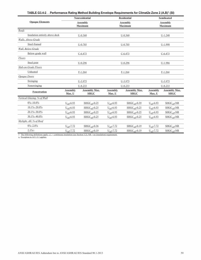
TABLE G3.4-2 Performance Rating Method Building Envelope Requirements for Climat2e Zone 2 (A,B)* (SI)
Opaque Elements
Nonresidential Residential Semiheated
AssemblyMaximum
AssemblyMaximum
AssemblyMaximum
Roofs
Insulation entirely above deck U-0.360 U-0.360 U-1.240
Walls, Above-Grade
Steel-framed U-0.705 U-0.705 U-1.998
Wall, Below-Grade
Below-grade wall C-6.473 C-6.473 C-6.473
Floors
Steel-joist U-0.296 U-0.296 U-1.986
Slab-on-Grade Floors
Unheated F-1.264 F-1.264 F-1.264
Opaque Doors
Swinging U-3.975 U-3.975 U-3.975
Nonswinging U-8.233 U-8.233 U-8.233
FenestrationAssemblyMax. U
Assembly Max.SHGC
AssemblyMax. U
Assembly Max.SHGC
AssemblyMax. U
Assembly Max.SHGC
Vertical Glazing, % of Wall
0%–10.0% Uall-6.93 SHGCall-0.25 Uall-6.93 SHGCall-0.39 Uall-6.93 SHGCall-NR
10.1%–20.0% Uall-6.93 SHGCall-0.25 Uall-6.93 SHGCall-0.25 Uall-6.93 SHGCall-NR
20.1%–30.0% Uall-6.93 SHGCall-0.25 Uall-6.93 SHGCall-0.25 Uall-6.93 SHGCall-NR
30.1%–40.0% Uall-6.93 SHGCall-0.25 Uall-6.93 SHGCall-0.25 Uall-6.93 SHGCall-NR
Skylight, All, % of Roof
0%–2.0% Uall-7.72 SHGCall-0.36 Uall-7.72 SHGCall-0.19 Uall-7.72 SHGCall-NR
2.1%+ Uall-7.72 SHGCall-0.19 Uall-7.72 SHGCall-0.19 Uall-7.72 SHGCall-NR
* The following definitions apply: c.i. = continuous insulation (see Section 3.2), NR = no (insulation) requirement.a. Exception to A3.1.3.1 applies.
ANSI/ASHRAE/IES Addendum bm to ANSI/ASHRAE/IES Standard 90.1-2013 59
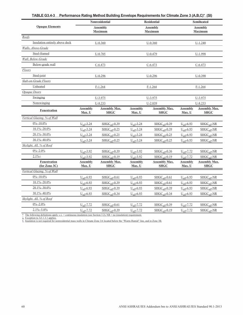
TABLE G3.4-3 Performance Rating Method Building Envelope Requirements for Climate Zone 3 (A,B,C)* (SI)
Opaque Elements
Nonresidential Residential Semiheated
AssemblyMaximum
AssemblyMaximum
AssemblyMaximum
Roofs
Insulation entirely above deck U-0.360 U-0.360 U-1.240
Walls, Above-Grade
Steel-framed U-0.705 U-0.479 U-1.998
Wall, Below-Grade
Below-grade wall C-6.473 C-6.473 C-6.473
Floors
Steel-joist U-0.296 U-0.296 U-0.390
Slab-on-Grade Floors
Unheated F-1.264 F-1.264 F-1.264
Opaque Doors
Swinging U-3.975 U-3.975 U-3.975
Nonswinging U-8.233 U-2.839 U-8.233
FenestrationAssemblyMax. U
Assembly Max.SHGC
AssemblyMax. U
Assembly Max.SHGC
AssemblyMax. U
Assembly Max.SHGC
Vertical Glazing, % of Wall
0%–10.0% Uall-3.24 SHGCall-0.39 Uall-3.24 SHGCall-0.39 Uall-6.93 SHGCall-NR
10.1%–20.0% Uall-3.24 SHGCall-0.25 Uall-3.24 SHGCall-0.39 Uall-6.93 SHGCall-NR
20.1%–30.0% Uall-3.24 SHGCall-0.25 Uall-3.24 SHGCall-0.25 Uall-6.93 SHGCall-NR
30.1%–40.0% Uall-3.24 SHGCall-0.25 Uall-3.24 SHGCall-0.25 Uall-6.93 SHGCall-NR
Skylight, All, % of Roof
0%–2.0% Uall-3.92 SHGCall-0.39 Uall-3.92 SHGCall-0.36 Uall-7.72 SHGCall-NR
2.1%+ Uall-3.92 SHGCall-0.19 Uall-3.92 SHGCall-0.19 Uall-7.72 SHGCall-NR
Fenestration(for Zone 3C)
AssemblyMax. U
Assembly Max.SHGC
AssemblyMax. U
Assembly Max.SHGC
AssemblyMax. U
Assembly Max.SHGC
Vertical Glazing, % of Wall
0%–10.0% Uall-6.93 SHGCall-0.61 Uall-6.93 SHGCall-0.61 Uall-6.93 SHGCall-NR
10.1%–20.0% Uall-6.93 SHGCall-0.39 Uall-6.93 SHGCall-0.61 Uall-6.93 SHGCall-NR
20.1%–30.0% Uall-6.93 SHGCall-0.39 Uall-6.93 SHGCall-0.39 Uall-6.93 SHGCall-NR
30.1%–40.0% Uall-6.93 SHGCall-0.34 Uall-6.93 SHGCall-0.34 Uall-6.93 SHGCall-NR
Skylight, All, % of Roof
0%–2.0% Uall-7.72 SHGCall-0.61 Uall-7.72 SHGCall-0.39 Uall-7.72 SHGCall-NR
2.1%–5.0% Uall-7.72 SHGCall-0.39 Uall-7.72 SHGCall-0.19 Uall-7.72 SHGCall-NR
* The following definitions apply: c.i. = continuous insulation (see Section 3.2), NR = no (insulation) requirement.a. Exception to A3.1.3.1 applies.b. Insulation is not required for nonresidential mass walls in Climate Zone 3A located below the “Warm-Humid” line, and in Zone 3B.
60 ANSI/ASHRAE/IES Addendum bm to ANSI/ASHRAE/IES Standard 90.1-2013

TABLE G3.4-4 Performance Rating Method Building Envelope Requirements for Climate Zone 4 (A,B,C)* (SI)
Opaque Elements
Nonresidential Residential Semiheated
AssemblyMaximum
AssemblyMaximum
AssemblyMaximum
Roofs
Insulation entirely above deck U-0.360 U-0.360 U-1.240
Walls, Above-Grade
Steel-framed U-0.705 U-0.365 U-0.705
Wall, Below-Grade
Below-grade wall C-6.473 C-6.473 C-6.473
Floors
Steel-joist U-0.296 U-0.214 U-0.390
Slab-on-Grade Floors
Unheated F-1.264 F-1.264 F-1.264
Opaque Doors
Swinging U-3.975 U-3.975 U-3.975
Nonswinging U-8.233 U-2.839 U-8.233
FenestrationAssemblyMax. U
Assembly Max.SHGC
AssemblyMax. U
Assembly Max.SHGC
AssemblyMax. U
Assembly Max.SHGC
Vertical Glazing, % of Wall
0%–10.0% Uall-3.24 SHGCall-0.39 Uall-3.24 SHGCall-0.39 Uall-6.93 SHGCall-NR
10.1%–20.0% Uall-3.24 SHGCall-0.39 Uall-3.24 SHGCall-0.39 Uall-6.93 SHGCall-NR
20.1%–30.0% Uall-3.24 SHGCall-0.39 Uall-3.24 SHGCall-0.39 Uall-6.93 SHGCall-NR
30.1%–40.0% Uall-3.24 SHGCall-0.39 Uall-3.24 SHGCall-0.39 Uall-6.93 SHGCall-NR
Skylight, All, % of Roof
0%–2.0% Uall-3.92 SHGCall-0.49 Uall-3.29 SHGCall-0.36 Uall-7.72 SHGCall-NR
2.1%+ Uall-3.92 SHGCall-0.39 Uall-3.29 SHGCall-0.19 Uall-7.72 SHGCall-NR
* The following definitions apply: c.i. = continuous insulation (see Section 3.2), NR = no (insulation) requirement.a. Exception to A3.1.3.1 applies.
ANSI/ASHRAE/IES Addendum bm to ANSI/ASHRAE/IES Standard 90.1-2013 61
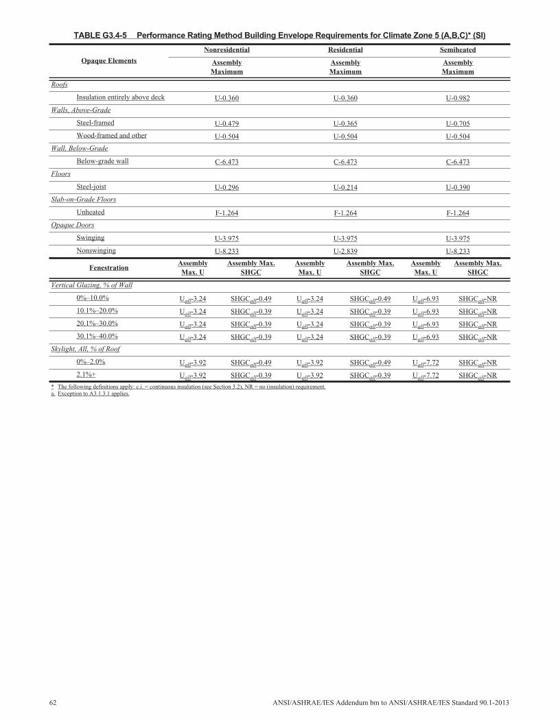
TABLE G3.4-5 Performance Rating Method Building Envelope Requirements for Climate Zone 5 (A,B,C)* (SI)
Opaque Elements
Nonresidential Residential Semiheated
AssemblyMaximum
AssemblyMaximum
AssemblyMaximum
Roofs
Insulation entirely above deck U-0.360 U-0.360 U-0.982
Walls, Above-Grade
Steel-framed U-0.479 U-0.365 U-0.705
Wood-framed and other U-0.504 U-0.504 U-0.504
Wall, Below-Grade
Below-grade wall C-6.473 C-6.473 C-6.473
Floors
Steel-joist U-0.296 U-0.214 U-0.390
Slab-on-Grade Floors
Unheated F-1.264 F-1.264 F-1.264
Opaque Doors
Swinging U-3.975 U-3.975 U-3.975
Nonswinging U-8.233 U-2.839 U-8.233
FenestrationAssemblyMax. U
Assembly Max.SHGC
AssemblyMax. U
Assembly Max.SHGC
AssemblyMax. U
Assembly Max.SHGC
Vertical Glazing, % of Wall
0%–10.0% Uall-3.24 SHGCall-0.49 Uall-3.24 SHGCall-0.49 Uall-6.93 SHGCall-NR
10.1%–20.0% Uall-3.24 SHGCall-0.39 Uall-3.24 SHGCall-0.39 Uall-6.93 SHGCall-NR
20.1%–30.0% Uall-3.24 SHGCall-0.39 Uall-3.24 SHGCall-0.39 Uall-6.93 SHGCall-NR
30.1%–40.0% Uall-3.24 SHGCall-0.39 Uall-3.24 SHGCall-0.39 Uall-6.93 SHGCall-NR
Skylight, All, % of Roof
0%–2.0% Uall-3.92 SHGCall-0.49 Uall-3.92 SHGCall-0.49 Uall-7.72 SHGCall-NR
2.1%+ Uall-3.92 SHGCall-0.39 Uall-3.92 SHGCall-0.39 Uall-7.72 SHGCall-NR
* The following definitions apply: c.i. = continuous insulation (see Section 3.2), NR = no (insulation) requirement.a. Exception to A3.1.3.1 applies.
62 ANSI/ASHRAE/IES Addendum bm to ANSI/ASHRAE/IES Standard 90.1-2013
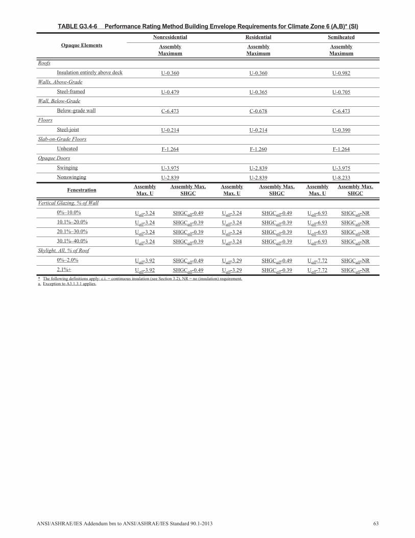
TABLE G3.4-6 Performance Rating Method Building Envelope Requirements for Climate Zone 6 (A,B)* (SI)
Opaque Elements
Nonresidential Residential Semiheated
AssemblyMaximum
AssemblyMaximum
AssemblyMaximum
Roofs
Insulation entirely above deck U-0.360 U-0.360 U-0.982
Walls, Above-Grade
Steel-framed U-0.479 U-0.365 U-0.705
Wall, Below-Grade
Below-grade wall C-6.473 C-0.678 C-6.473
Floors
Steel-joist U-0.214 U-0.214 U-0.390
Slab-on-Grade Floors
Unheated F-1.264 F-1.260 F-1.264
Opaque Doors
Swinging U-3.975 U-2.839 U-3.975
Nonswinging U-2.839 U-2.839 U-8.233
FenestrationAssemblyMax. U
Assembly Max.SHGC
AssemblyMax. U
Assembly Max.SHGC
AssemblyMax. U
Assembly Max.SHGC
Vertical Glazing, % of Wall
0%–10.0% Uall-3.24 SHGCall-0.49 Uall-3.24 SHGCall-0.49 Uall-6.93 SHGCall-NR
10.1%–20.0% Uall-3.24 SHGCall-0.39 Uall-3.24 SHGCall-0.39 Uall-6.93 SHGCall-NR
20.1%–30.0% Uall-3.24 SHGCall-0.39 Uall-3.24 SHGCall-0.39 Uall-6.93 SHGCall-NR
30.1%–40.0% Uall-3.24 SHGCall-0.39 Uall-3.24 SHGCall-0.39 Uall-6.93 SHGCall-NR
Skylight, All, % of Roof
0%–2.0% Uall-3.92 SHGCall-0.49 Uall-3.29 SHGCall-0.49 Uall-7.72 SHGCall-NR
2.1%+ Uall-3.92 SHGCall-0.49 Uall-3.29 SHGCall-0.39 Uall-7.72 SHGCall-NR
* The following definitions apply: c.i. = continuous insulation (see Section 3.2), NR = no (insulation) requirement.a. Exception to A3.1.3.1 applies.
ANSI/ASHRAE/IES Addendum bm to ANSI/ASHRAE/IES Standard 90.1-2013 63

TABLE G3.4-7 Performance Rating Method Building Envelope Requirements for Climate Zone 7* (SI)
Opaque Elements
Nonresidential Residential Semiheated
AssemblyMaximum
AssemblyMaximum
AssemblyMaximum
Roofs
Insulation entirely above deck U-0.360 U-0.360 U-0.982
Walls, Above-Grade
Steel-framed U-0.365 U-0.365 U-0.705
Wall, Below-Grade
Below-grade wall C-0.678 C-0.678 C-6.473
Floors
Steel-joist U-0.214 U-0.214 U-0.296
Slab-on-Grade Floors
Unheated F-1.264 F-0.935 F-1.264
Opaque Doors
Swinging U-3.975 U-2.839 U-3.975
Nonswinging U-2.839 U-2.839 U-8.233
FenestrationAssemblyMax. U
Assembly Max.SHGC
AssemblyMax. U
Assembly Max.SHGC
AssemblyMax. U
Assembly Max.SHGC
Vertical Glazing, % of Wall
0%–10.0% Uall-3.24 SHGCall-0.49 Uall-3.24 SHGCall-0.49 Uall-6.93 SHGCall-NR
10.1%–20.0% Uall-3.24 SHGCall-0.49 Uall-3.24 SHGCall-0.49 Uall-6.93 SHGCall-NR
20.1%–30.0% Uall-3.24 SHGCall-0.49 Uall-3.24 SHGCall-0.49 Uall-6.93 SHGCall-NR
30.1%–40.0% Uall-3.24 SHGCall-0.49 Uall-3.24 SHGCall-0.49 Uall-6.93 SHGCall-NR
Skylight, All, % of Roof
0%–2.0% Uall-3.92 SHGCall-0.68 Uall-3.92 SHGCall-0.64 Uall-7.72 SHGCall-NR
2.1%+ Uall-3.92 SHGCall-0.64 Uall-3.92 SHGCall-0.64 Uall-7.72 SHGCall-NR
* The following definitions apply: c.i. = continuous insulation (see Section 3.2), NR = no (insulation) requirement.a. Exception to A3.1.3.1 applies.
64 ANSI/ASHRAE/IES Addendum bm to ANSI/ASHRAE/IES Standard 90.1-2013
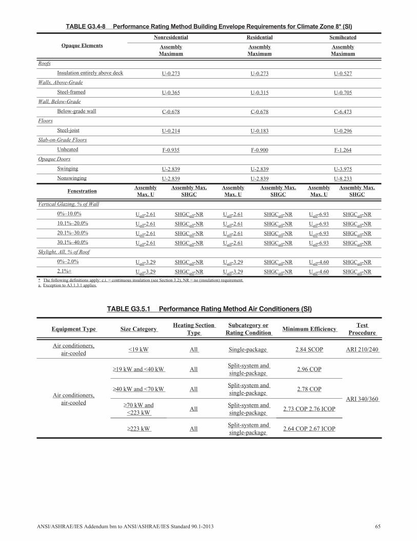
TABLE G3.4-8 Performance Rating Method Building Envelope Requirements for Climate Zone 8* (SI)
Opaque Elements
Nonresidential Residential Semiheated
AssemblyMaximum
AssemblyMaximum
AssemblyMaximum
Roofs
Insulation entirely above deck U-0.273 U-0.273 U-0.527
Walls, Above-Grade
Steel-framed U-0.365 U-0.315 U-0.705
Wall, Below-Grade
Below-grade wall C-0.678 C-0.678 C-6.473
Floors
Steel-joist U-0.214 U-0.183 U-0.296
Slab-on-Grade Floors
Unheated F-0.935 F-0.900 F-1.264
Opaque Doors
Swinging U-2.839 U-2.839 U-3.975
Nonswinging U-2.839 U-2.839 U-8.233
FenestrationAssemblyMax. U
Assembly Max.SHGC
AssemblyMax. U
Assembly Max.SHGC
AssemblyMax. U
Assembly Max.SHGC
Vertical Glazing, % of Wall
0%–10.0% Uall-2.61 SHGCall-NR Uall-2.61 SHGCall-NR Uall-6.93 SHGCall-NR
10.1%–20.0% Uall-2.61 SHGCall-NR Uall-2.61 SHGCall-NR Uall-6.93 SHGCall-NR
20.1%–30.0% Uall-2.61 SHGCall-NR Uall-2.61 SHGCall-NR Uall-6.93 SHGCall-NR
30.1%–40.0% Uall-2.61 SHGCall-NR Uall-2.61 SHGCall-NR Uall-6.93 SHGCall-NR
Skylight, All, % of Roof
0%–2.0% Uall-3.29 SHGCall-NR Uall-3.29 SHGCall-NR Uall-4.60 SHGCall-NR
2.1%+ Uall-3.29 SHGCall-NR Uall-3.29 SHGCall-NR Uall-4.60 SHGCall-NR
* The following definitions apply: c.i. = continuous insulation (see Section 3.2), NR = no (insulation) requirement.a. Exception to A3.1.3.1 applies.
TABLE G3.5.1 Performance Rating Method Air Conditioners (SI)
Equipment Type Size CategoryHeating Section
TypeSubcategory or
Rating ConditionMinimum Efficiency
TestProcedure
Air conditioners,air-cooled
<19 kW All Single-package 2.84 SCOP ARI 210/240
Air conditioners,air-cooled
19 kW and <40 kW AllSplit-system andsingle-package
2.96 COP
ARI 340/360
40 kW and <70 kW AllSplit-system andsingle-package
2.78 COP
70 kW and<223 kW
AllSplit-system andsingle-package
2.73 COP 2.76 ICOP
223 kW AllSplit-system andsingle-package
2.64 COP 2.67 ICOP
ANSI/ASHRAE/IES Addendum bm to ANSI/ASHRAE/IES Standard 90.1-2013 65
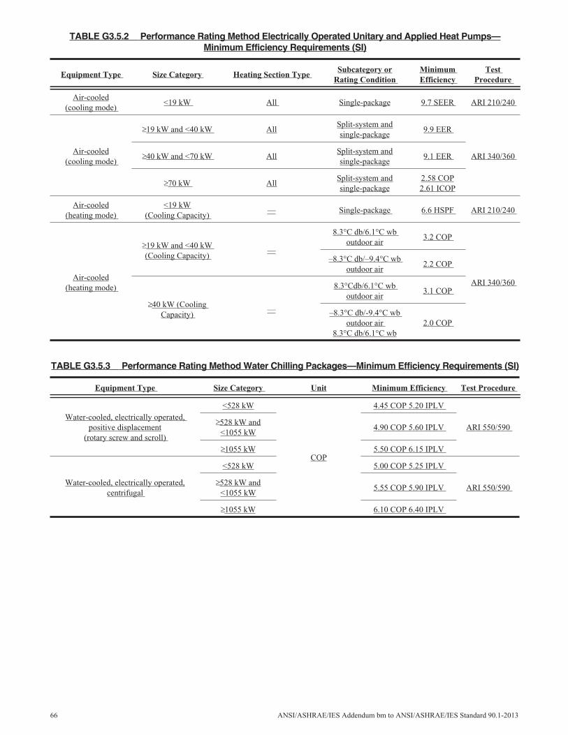
TABLE G3.5.2 Performance Rating Method Electrically Operated Unitary and Applied Heat Pumps—Minimum Efficiency Requirements (SI)
Equipment Type Size Category Heating Section TypeSubcategory or
Rating ConditionMinimumEfficiency
TestProcedure
Air-cooled(cooling mode)
<19 kW All Single-package 9.7 SEER ARI 210/240
Air-cooled(cooling mode)
19 kW and <40 kW AllSplit-system andsingle-package
9.9 EER
ARI 340/36040 kW and <70 kW AllSplit-system andsingle-package
9.1 EER
70 kW AllSplit-system andsingle-package
2.58 COP2.61 ICOP
Air-cooled(heating mode)
<19 kW(Cooling Capacity)
— Single-package 6.6 HSPF ARI 210/240
Air-cooled(heating mode)
19 kW and <40 kW(Cooling Capacity)
—
8.3°C db/6.1°C wboutdoor air
3.2 COP
ARI 340/360
–8.3°C db/–9.4°C wboutdoor air
2.2 COP
40 kW (CoolingCapacity)
—
8.3°Cdb/6.1°C wboutdoor air
3.1 COP
–8.3°C db/-9.4°C wboutdoor air
8.3°C db/6.1°C wb2.0 COP
TABLE G3.5.3 Performance Rating Method Water Chilling Packages—Minimum Efficiency Requirements (SI)
Equipment Type Size Category Unit Minimum Efficiency Test Procedure
Water-cooled, electrically operated,positive displacement
(rotary screw and scroll)
<528 kW
COP
4.45 COP 5.20 IPLV
ARI 550/590528 kW and
<1055 kW4.90 COP 5.60 IPLV
1055 kW 5.50 COP 6.15 IPLV
Water-cooled, electrically operated,centrifugal
<528 kW 5.00 COP 5.25 IPLV
ARI 550/590528 kW and
<1055 kW5.55 COP 5.90 IPLV
1055 kW 6.10 COP 6.40 IPLV
66 ANSI/ASHRAE/IES Addendum bm to ANSI/ASHRAE/IES Standard 90.1-2013
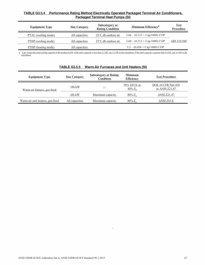
TABLE G3.5.4 Performance Rating Method Electrically Operated Packaged Terminal Air Conditioners,Packaged Terminal Heat Pumps (SI)
Equipment Type Size CategorySubcategory or
Rating ConditionMinimum Efficiencya Test
Procedure
PTAC (cooling mode) All capacities 35°C db outdoor air 3.66 – (0.213 × Cap/1000) COP
ARI 310/380PTHP (cooling mode) All capacities 35°C db outdoor air 3.60 – (0.213 × Cap/1000) COP
PTHP (heating mode) All capacities 3.2 – (0.026 × Cap/1000) COP
a. “Cap” means the rated cooling capacity of the product in kW. If the unit's capacity is less than 2.1 kW, use 2.1 kW in the calculation. If the unit's capacity is greater than 4.4 kW, use 4.4 kW in thecalculation.
TABLE G3.5.5 Warm-Air Furnaces and Unit Heaters (SI)
Equipment Type Size CategorySubcategory or Rating
ConditionMinimumEfficiency
Test Procedure
Warm-air furnace, gas-fired<66 kW —
78% AFUE or80% Et
DOE 10 CFR Part 430or ANSI Z21.47
66 kW Maximum capacity 80% Ec ANSI Z21.47
Warm-air unit heaters, gas-fired All capacities Maximum capacity 80% Ec ANSI Z83.8
ANSI/ASHRAE/IES Addendum bm to ANSI/ASHRAE/IES Standard 90.1-2013 67
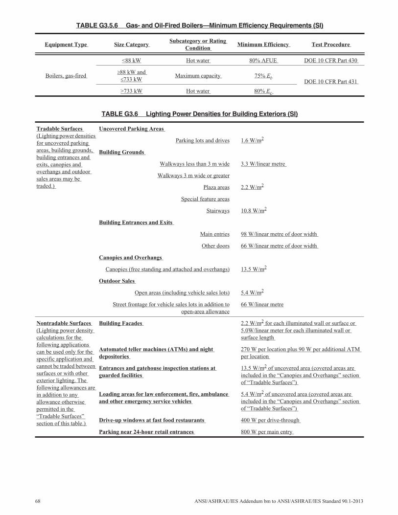
TABLE G3.5.6 Gas- and Oil-Fired Boilers—Minimum Efficiency Requirements (SI)
Equipment Type Size CategorySubcategory or Rating
ConditionMinimum Efficiency Test Procedure
Boilers, gas-fired
<88 kW Hot water 80% AFUE DOE 10 CFR Part 430
88 kW and733 kW
Maximum capacity 75% EtDOE 10 CFR Part 431
>733 kW Hot water 80% Ec
TABLE G3.6 Lighting Power Densities for Building Exteriors (SI)
Tradable Surfaces(Lighting power densitiesfor uncovered parkingareas, building grounds,building entrances andexits, canopies andoverhangs and outdoorsales areas may betraded.)
Uncovered Parking Areas
Parking lots and drives 1.6 W/m2
Building Grounds
Walkways less than 3 m wide 3.3 W/linear metre
Walkways 3 m wide or greater
Plaza areas 2.2 W/m2
Special feature areas
Stairways 10.8 W/m2
Building Entrances and Exits
Main entries 98 W/linear metre of door width
Other doors 66 W/linear metre of door width
Canopies and Overhangs
Canopies (free standing and attached and overhangs) 13.5 W/m2
Outdoor Sales
Open areas (including vehicle sales lots) 5.4 W/m2
Street frontage for vehicle sales lots in addition toopen-area allowance
66 W/linear metre
Nontradable Surfaces(Lighting power densitycalculations for thefollowing applicationscan be used only for thespecific application andcannot be traded betweensurfaces or with otherexterior lighting. Thefollowing allowances arein addition to anyallowance otherwisepermitted in the“Tradable Surfaces”section of this table.)
Building Facades 2.2 W/m2 for each illuminated wall or surface or5.0W/linear meter for each illuminated wall orsurface length
Automated teller machines (ATMs) and nightdepositories
270 W per location plus 90 W per additional ATMper location
Entrances and gatehouse inspection stations atguarded facilities
13.5 W/m2 of uncovered area (covered areas areincluded in the “Canopies and Overhangs” sectionof “Tradable Surfaces”)
Loading areas for law enforcement, fire, ambulanceand other emergency service vehicles
5.4 W/m2 of uncovered area (covered areas areincluded in the “Canopies and Overhangs” sectionof “Tradable Surfaces”)
Drive-up windows at fast food restaurants 400 W per drive-through
Parking near 24-hour retail entrances 800 W per main entry
68 ANSI/ASHRAE/IES Addendum bm to ANSI/ASHRAE/IES Standard 90.1-2013
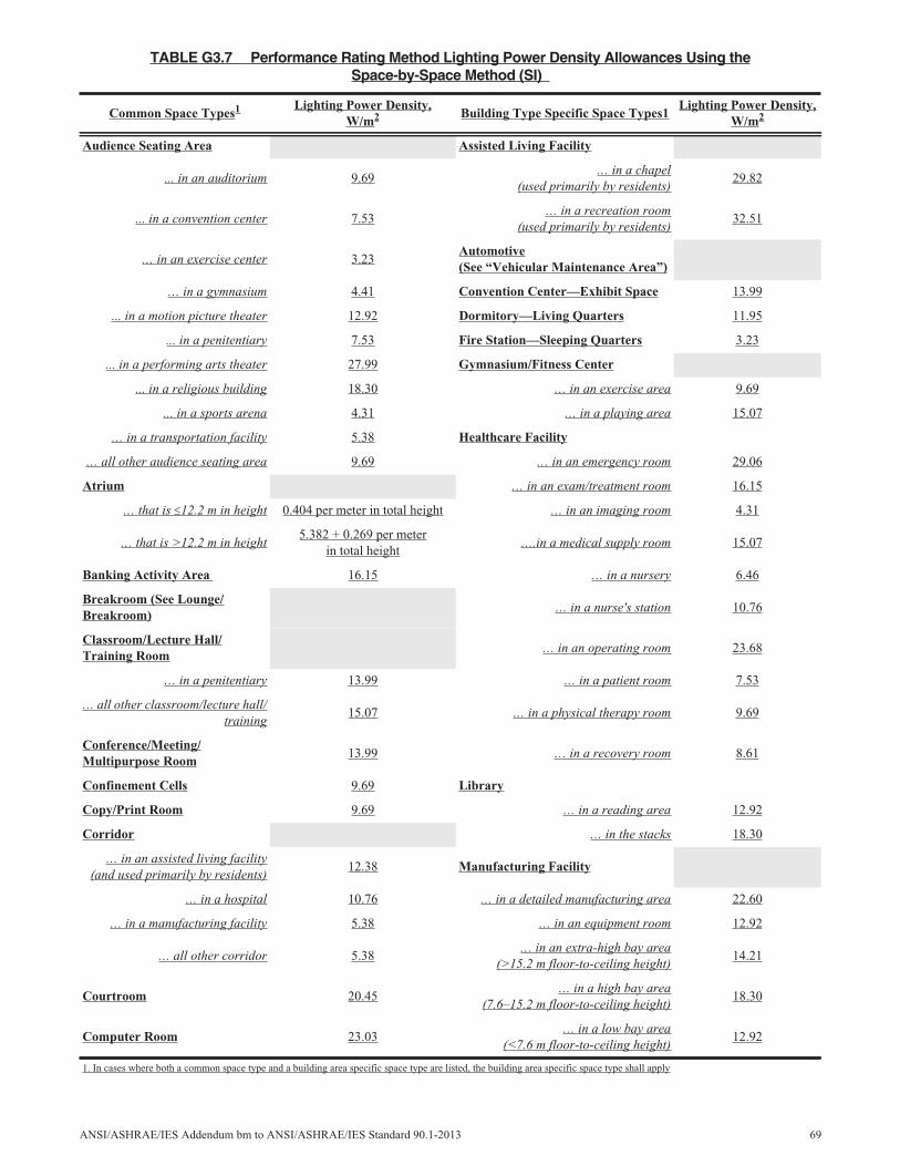
TABLE G3.7 Performance Rating Method Lighting Power Density Allowances Using theSpace-by-Space Method (SI)
Common Space Types1 Lighting Power Density,W/m2 Building Type Specific Space Types1
Lighting Power Density,W/m2
Audience Seating Area Assisted Living Facility
... in an auditorium 9.69… in a chapel
(used primarily by residents)29.82
... in a convention center 7.53… in a recreation room
(used primarily by residents)32.51
… in an exercise center 3.23Automotive(See “Vehicular Maintenance Area”)
… in a gymnasium 4.41 Convention Center—Exhibit Space 13.99
... in a motion picture theater 12.92 Dormitory—Living Quarters 11.95
... in a penitentiary 7.53 Fire Station—Sleeping Quarters 3.23
... in a performing arts theater 27.99 Gymnasium/Fitness Center
... in a religious building 18.30 … in an exercise area 9.69
... in a sports arena 4.31 … in a playing area 15.07
… in a transportation facility 5.38 Healthcare Facility
… all other audience seating area 9.69 … in an emergency room 29.06
Atrium … in an exam/treatment room 16.15
… that is 12.2 m in height 0.404 per meter in total height … in an imaging room 4.31
… that is >12.2 m in height5.382 + 0.269 per meter
in total height….in a medical supply room 15.07
Banking Activity Area 16.15 … in a nursery 6.46
Breakroom (See Lounge/Breakroom)
… in a nurse's station 10.76
Classroom/Lecture Hall/Training Room
… in an operating room 23.68
… in a penitentiary 13.99 … in a patient room 7.53
… all other classroom/lecture hall/training
15.07 … in a physical therapy room 9.69
Conference/Meeting/Multipurpose Room
13.99 … in a recovery room 8.61
Confinement Cells 9.69 Library
Copy/Print Room 9.69 … in a reading area 12.92
Corridor … in the stacks 18.30
… in an assisted living facility(and used primarily by residents)
12.38 Manufacturing Facility
… in a hospital 10.76 … in a detailed manufacturing area 22.60
… in a manufacturing facility 5.38 … in an equipment room 12.92
… all other corridor 5.38… in an extra-high bay area
(>15.2 m floor-to-ceiling height)14.21
Courtroom 20.45… in a high bay area
(7.6–15.2 m floor-to-ceiling height)18.30
Computer Room 23.03… in a low bay area
(<7.6 m floor-to-ceiling height)12.92
1. In cases where both a common space type and a building area specific space type are listed, the building area specific space type shall apply
ANSI/ASHRAE/IES Addendum bm to ANSI/ASHRAE/IES Standard 90.1-2013 69
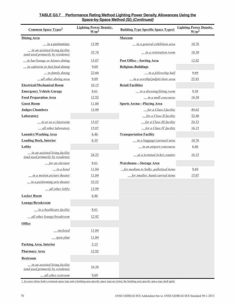
Dining Area Museum
… in a penitentiary 13.99 … in a general exhibition area 10.76
… in an assisted living facility(and used primarily by residents)
35.74 … in a restoration room 18.30
… in bar/lounge or leisure dining 15.07 Post Office—Sorting Area 12.92
… in cafeteria or fast food dining 9.69 Religious Buildings
… in family dining 22.60 … in a fellowship hall 9.69
… all other dining area 9.69 … in a worship/pulpit/choir area 25.83
Electrical/Mechanical Room 16.15 Retail Facilities
Emergency Vehicle Garage 8.61 … in a dressing/fitting room 9.58
Food Preparation Area 12.92 … in a mall concourse 18.30
Guest Room 11.84 Sports Arena—Playing Area
Judges Chambers 13.99 … for a Class I facility 49.62
Laboratory … for a Class II facility 32.40
… in or as a classroom 15.07 … for a Class III facility 24.33
… all other laboratory 15.07 … for a Class IV facility 16.15
Laundry/Washing Area 6.46 Transportation Facility
Loading Dock, Interior 6.35 … in a baggage/carousel area 10.76
Lobby … in an airport concourse 6.46
… in an assisted living facility(and used primarily by residents)
24.33 … at a terminal ticket counter 16.15
… for an elevator 8.61 Warehouse—Storage Area
… in a hotel 11.84 …for medium to bulky, palletized items 9.69
… in a motion picture theater 11.84 … for smaller, hand-carried items 15.07
… in a performing arts theater 35.52
… all other lobby 13.99
Locker Room 6.46
Lounge/Breakroom
… in a healthcare facility 8.61
… all other lounge/breakroom 12.92
Office
… enclosed 11.84
… open plan 11.84
Parking Area, Interior 2.15
Pharmacy Area 12.92
Restroom
… in an assisted living facility(and used primarily by residents)
16.36
… all other restroom 9.69
TABLE G3.7 Performance Rating Method Lighting Power Density Allowances Using theSpace-by-Space Method (SI) (Continued)
Common Space Types1 Lighting Power Density,W/m2 Building Type Specific Space Types1
Lighting Power Density,W/m2
1. In cases where both a common space type and a building area specific space type are listed, the building area specific space type shall apply
70 ANSI/ASHRAE/IES Addendum bm to ANSI/ASHRAE/IES Standard 90.1-2013
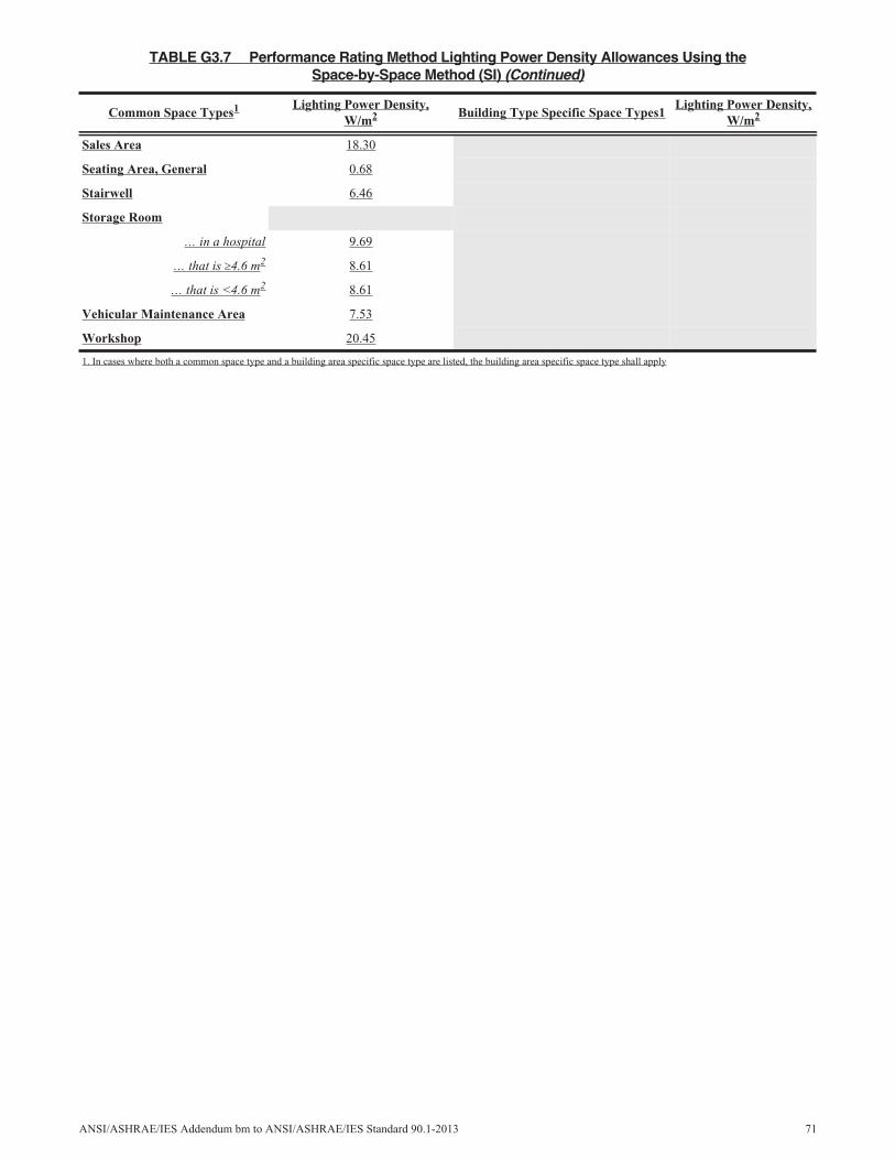
Sales Area 18.30
Seating Area, General 0.68
Stairwell 6.46
Storage Room
… in a hospital 9.69
… that is 4.6 m2 8.61
… that is <4.6 m2 8.61
Vehicular Maintenance Area 7.53
Workshop 20.45
TABLE G3.7 Performance Rating Method Lighting Power Density Allowances Using theSpace-by-Space Method (SI) (Continued)
Common Space Types1 Lighting Power Density,W/m2 Building Type Specific Space Types1
Lighting Power Density,W/m2
1. In cases where both a common space type and a building area specific space type are listed, the building area specific space type shall apply
ANSI/ASHRAE/IES Addendum bm to ANSI/ASHRAE/IES Standard 90.1-2013 71
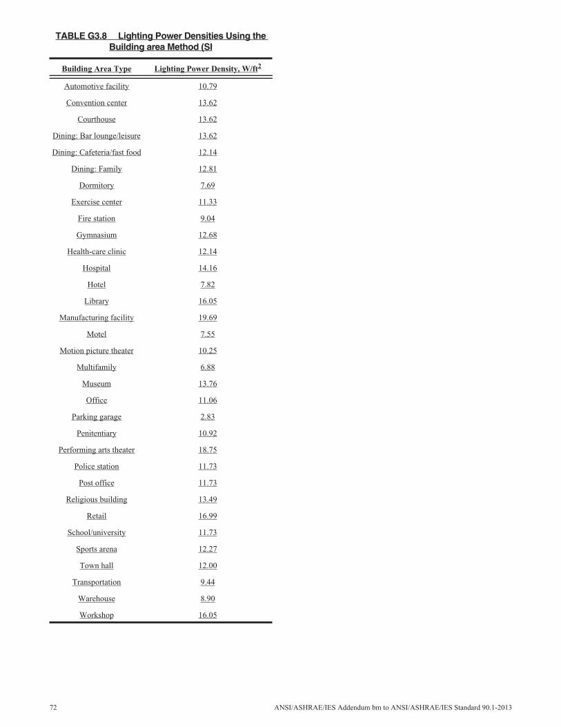
TABLE G3.8 Lighting Power Densities Using theBuilding area Method (SI
Building Area Type Lighting Power Density, W/ft2
Automotive facility 10.79
Convention center 13.62
Courthouse 13.62
Dining: Bar lounge/leisure 13.62
Dining: Cafeteria/fast food 12.14
Dining: Family 12.81
Dormitory 7.69
Exercise center 11.33
Fire station 9.04
Gymnasium 12.68
Health-care clinic 12.14
Hospital 14.16
Hotel 7.82
Library 16.05
Manufacturing facility 19.69
Motel 7.55
Motion picture theater 10.25
Multifamily 6.88
Museum 13.76
Office 11.06
Parking garage 2.83
Penitentiary 10.92
Performing arts theater 18.75
Police station 11.73
Post office 11.73
Religious building 13.49
Retail 16.99
School/university 11.73
Sports arena 12.27
Town hall 12.00
Transportation 9.44
Warehouse 8.90
Workshop 16.05
72 ANSI/ASHRAE/IES Addendum bm to ANSI/ASHRAE/IES Standard 90.1-2013
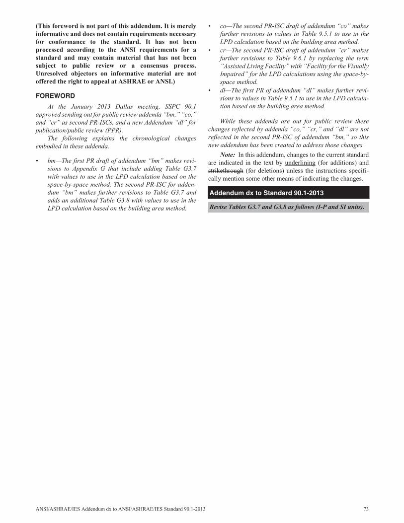
(This foreword is not part of this addendum. It is merelyinformative and does not contain requirements necessaryfor conformance to the standard. It has not beenprocessed according to the ANSI requirements for astandard and may contain material that has not beensubject to public review or a consensus process.Unresolved objectors on informative material are notoffered the right to appeal at ASHRAE or ANSI.)
FOREWORD
At the January 2013 Dallas meeting, SSPC 90.1approved sending out for public review addenda “bm,” “co,”and “cr” as second PR-ISCs, and a new Addendum “dl” forpublication/public review (PPR).
The following explains the chronological changesembodied in these addenda.
• bm—The first PR draft of addendum “bm” makes revi-sions to Appendix G that include adding Table G3.7with values to use in the LPD calculation based on thespace-by-space method. The second PR-ISC for adden-dum “bm” makes further revisions to Table G3.7 andadds an additional Table G3.8 with values to use in theLPD calculation based on the building area method.
• co—The second PR-ISC draft of addendum “co” makesfurther revisions to values in Table 9.5.1 to use in theLPD calculation based on the building area method.
• cr—The second PR-ISC draft of addendum “cr” makesfurther revisions to Table 9.6.1 by replacing the term“Assisted Living Facility” with “Facility for the VisuallyImpaired” for the LPD calculations using the space-by-space method.
• dl—The first PR of addendum “dl” makes further revi-sions to values in Table 9.5.1 to use in the LPD calcula-tion based on the building area method.
While these addenda are out for public review thesechanges reflected by addenda “co,” “cr,” and “dl” are notreflected in the second PR-ISC of addendum “bm,” so thisnew addendum has been created to address those changes
Note: In this addendum, changes to the current standardare indicated in the text by underlining (for additions) andstrikethrough (for deletions) unless the instructions specifi-cally mention some other means of indicating the changes.
Addendum dx to Standard 90.1-2013
Revise Tables G3.7 and G3.8 as follows (I-P and SI units).
ANSI/ASHRAE/IES Addendum dx to ANSI/ASHRAE/IES Standard 90.1-2013 73
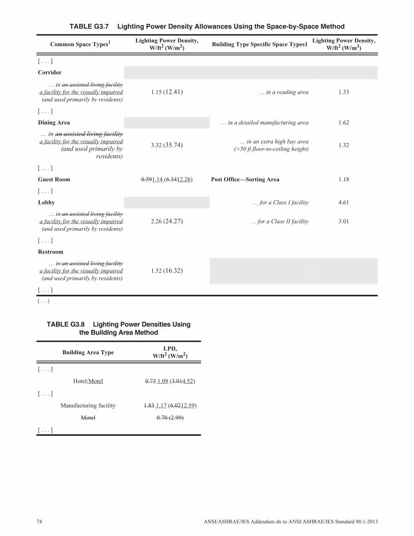
TABLE G3.7 Lighting Power Density Allowances Using the Space-by-Space Method
Common Space Types1 Lighting Power Density,W/ft2 (W/m2)
Building Type Specific Space Types1Lighting Power Density,
W/ft2 (W/m2)
[ . . . ]
Corridor
… in an assisted living facilitya facility for the visually impaired(and used primarily by residents)
1.15 (12.41) … in a reading area 1.33
[ . . . ]
Dining Area … in a detailed manufacturing area 1.62
… in an assisted living facilitya facility for the visually impaired
(and used primarily byresidents)
3.32 (35.74) … in an extra high bay area(>50 ft floor-to-ceiling height)
1.32
[ . . . ]
Guest Room 0.591.14 (6.3412.26) Post Office—Sorting Area 1.18
[ . . . ]
Lobby … for a Class I facility 4.61
… in an assisted living facilitya facility for the visually impaired(and used primarily by residents)
2.26 (24.27) … for a Class II facility 3.01
[ . . . ]
Restroom
… in an assisted living facilitya facility for the visually impaired(and used primarily by residents)
1.52 (16.32)
[ . . . ]
[ . . . ]
TABLE G3.8 Lighting Power Densities Usingthe Building Area Method
Building Area TypeLPD,
W/ft2 (W/m2)
[ . . . ]
Hotel/Motel 0.73 1.09 (3.014.52)
[ . . . ]
Manufacturing facility 1.83 1.17 (6.0212.59)
Motel 0.70 (2.99)
[ . . . ]
74 ANSI/ASHRAE/IES Addendum dx to ANSI/ASHRAE/IES Standard 90.1-2013
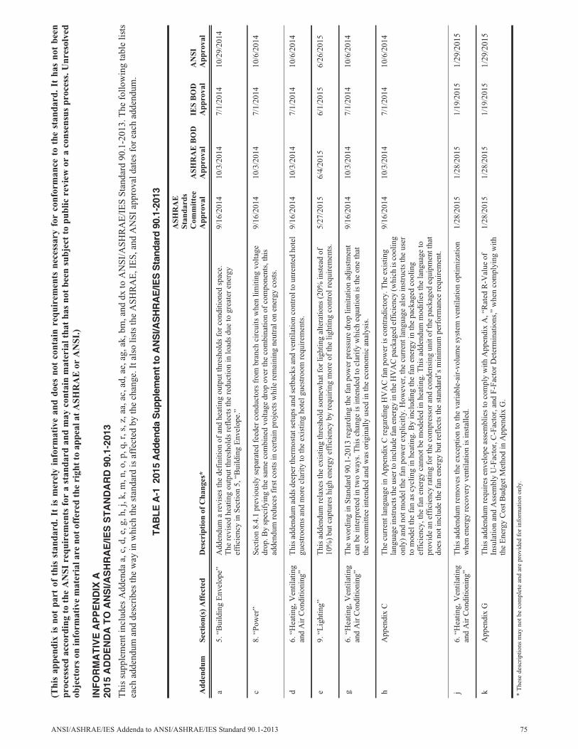
(Thi
sap
pend
ixis
not
part
ofth
isst
anda
rd.
Itis
mer
ely
info
rmat
ive
and
does
not
cont
ain
requ
irem
ents
nece
ssar
yfo
rco
nfor
man
ceto
the
stan
dard
.It
has
not
been
proc
esse
dac
cord
ing
toth
eA
NSI
requ
irem
ents
for
ast
anda
rdan
dm
ayco
ntai
nm
ater
ialt
hat
has
not
been
subj
ect
topu
blic
revi
ewor
aco
nsen
sus
proc
ess.
Unr
esol
ved
obje
ctor
son
info
rmat
ive
mat
eria
lare
not
offe
red
the
righ
tto
appe
alat
ASH
RA
Eor
AN
SI.)
INF
OR
MA
TIV
EA
PP
EN
DIX
A20
15A
DD
EN
DA
TO
AN
SI/A
SH
RA
E/IE
SS
TA
ND
AR
D90
.1-2
013
Thi
ssu
pple
men
tinc
lude
sA
dden
daa,
c,d,
e,g,
h,j,
k,m
,n,o
,p,q
,r,s
,z,a
a,ac
,ad,
ae,a
g,ak
,bm
,and
dxto
AN
SI/A
SHR
AE
/IE
SSt
anda
rd90
.1-2
013.
The
follo
win
gta
ble
lists
each
adde
ndum
and
desc
ribe
sth
ew
ayin
whi
chth
est
anda
rdis
affe
cted
byth
ech
ange
.Ita
lso
lists
the
ASH
RA
E,I
ES,
and
AN
SIap
prov
alda
tes
for
each
adde
ndum
.
TAB
LEA
-120
15A
dden
daS
uppl
emen
tto
AN
SI/A
SH
RA
E/IE
SS
tand
ard
90.1
-201
3
Add
endu
mSe
ctio
n(s)
Aff
ecte
dD
escr
ipti
onof
Cha
nges
*
ASH
RA
ESt
anda
rds
Com
mit
tee
App
rova
lA
SHR
AE
BO
DA
ppro
val
IES
BO
DA
ppro
val
AN
SIA
ppro
val
a5.
“Bui
ldin
gE
nvel
ope”
Add
endu
ma
revi
ses
the
defi
nitio
nof
and
heat
ing
outp
utth
resh
olds
for
cond
ition
edsp
ace.
The
revi
sed
heat
ing
outp
utth
resh
olds
refl
ects
the
redu
ctio
nin
load
sdu
eto
grea
ter
ener
gyef
fici
ency
inSe
ctio
n5,
“Bui
ldin
gE
nvel
ope.
”
9/16
/201
410
/3/2
014
7/1/
2014
10/2
9/20
14
c8.
“Pow
er”
Sect
ion
8.4.
1pr
evio
usly
sepa
rate
dfe
eder
cond
ucto
rsfr
ombr
anch
circ
uits
whe
nlim
iting
volta
gedr
op.B
ysp
ecif
ying
the
sam
eco
mbi
ned
volta
gedr
opov
erth
eco
mbi
natio
nof
com
pone
nts,
this
adde
ndum
redu
ces
firs
tcos
tsin
cert
ain
proj
ects
whi
lere
mai
ning
neut
ralo
nen
ergy
cost
s.
9/16
/201
410
/3/2
014
7/1/
2014
10/6
/201
4
d6.
“Hea
ting,
Ven
tilat
ing
and
Air
Con
ditio
ning
”T
his
adde
ndum
adds
deep
erth
erm
osta
tset
ups
and
setb
acks
and
vent
ilatio
nco
ntro
lto
unre
nted
hote
lgu
estr
oom
san
dm
ore
clar
ityto
the
exis
ting
hote
lgue
stro
omre
quir
emen
ts.
9/16
/201
410
/3/2
014
7/1/
2014
10/6
/201
4
e9.
“Lig
htin
g”T
his
adde
ndum
rela
xes
the
exis
ting
thre
shol
dso
mew
hatf
orlig
htin
gal
tera
tions
(20%
inst
ead
of10
%)
butc
aptu
res
high
ener
gyef
fici
ency
byre
quir
ing
mor
eof
the
light
ing
cont
rolr
equi
rem
ents
.5/
27/2
015
6/4/
2015
6/1/
2015
6/26
/201
5
g6.
“Hea
ting,
Ven
tilat
ing
and
Air
Con
ditio
ning
”T
hew
ordi
ngin
Stan
dard
90.1
-201
3re
gard
ing
the
fan
pow
erpr
essu
redr
oplim
itatio
nad
just
men
tca
nbe
inte
rpre
ted
intw
ow
ays.
Thi
sch
ange
isin
tend
edto
clar
ify
whi
cheq
uatio
nis
the
one
that
the
com
mitt
eein
tend
edan
dw
asor
igin
ally
used
inth
eec
onom
ican
alys
is.
9/16
/201
410
/3/2
014
7/1/
2014
10/6
/201
4
hA
ppen
dix
CT
hecu
rren
tlan
guag
ein
App
endi
xC
rega
rdin
gH
VA
Cfa
npo
wer
isco
ntra
dict
ory.
The
exis
ting
lang
uage
inst
ruct
sth
eus
erto
incl
ude
fan
ener
gyin
the
HV
AC
pack
aged
effi
cien
cy(w
hich
isco
olin
gon
ly)
and
notm
odel
the
fan
pow
erex
plic
itly.
How
ever
,the
curr
entl
angu
age
also
inst
ruct
sth
eus
erto
mod
elth
efa
nas
cycl
ing
inhe
atin
g.B
yin
clud
ing
the
fan
ener
gyin
the
pack
aged
cool
ing
effi
cien
cy,t
hefa
nen
ergy
cann
otbe
mod
eled
inhe
atin
g.T
his
adde
ndum
mod
ifie
sth
ela
ngua
geto
prov
ide
anef
fici
ency
ratin
gfo
rthe
com
pres
sora
ndco
nden
sing
unit
ofth
epa
ckag
edeq
uipm
entt
hat
does
noti
nclu
deth
efa
nen
ergy
butr
efle
cts
the
stan
dard
’sm
inim
umpe
rfor
man
cere
quir
emen
t.
9/16
/201
410
/3/2
014
7/1/
2014
10/6
/201
4
j6.
“Hea
ting,
Ven
tilat
ing
and
Air
Con
ditio
ning
”T
his
adde
ndum
rem
oves
the
exce
ptio
nto
the
vari
able
-air
-vol
ume
syst
emve
ntila
tion
optim
izat
ion
whe
nen
ergy
reco
very
vent
ilatio
nis
inst
alle
d.1/
28/2
015
1/28
/201
51/
19/2
015
1/29
/201
5
kA
ppen
dix
GT
his
adde
ndum
requ
ires
enve
lope
asse
mbl
ies
toco
mpl
yw
ithA
ppen
dix
A,“
Rat
edR
-Val
ueof
Insu
latio
nan
dA
ssem
bly
U-F
acto
r,C
-Fac
tor,
and
F-Fa
ctor
Det
erm
inat
ions
,”w
hen
com
plyi
ngw
ithth
eE
nerg
yC
ostB
udge
tMet
hod
inA
ppen
dix
G.
1/28
/201
51/
28/2
015
1/19
/201
51/
29/2
015
*T
hese
desc
ript
ions
may
notb
eco
mpl
ete
and
are
prov
ided
for
info
rmat
ion
only
.
ANSI/ASHRAE/IES Addenda to ANSI/ASHRAE/IES Standard 90.1-2013 75
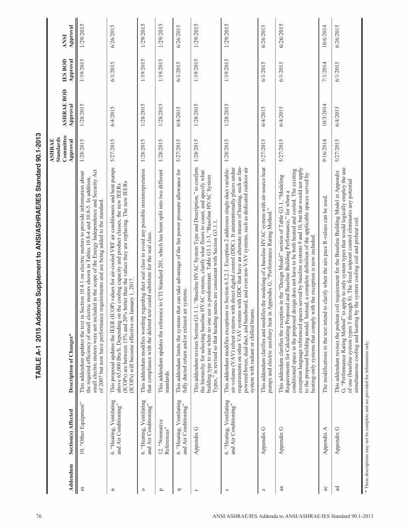
m10
.“O
ther
Equ
ipm
ent”
Thi
sad
dend
umup
date
sth
ete
xtin
Sect
ion
10.4
.1on
elec
tric
mot
ors
topr
ovid
ein
form
atio
nab
out
the
requ
ired
effi
cien
cyof
smal
lele
ctri
cm
otor
ssh
own
inT
able
s10
.8-4
and
10.8
-5.I
nad
ditio
n,sm
alle
lect
ric
mot
ors
wer
eno
tinc
lude
din
the
scop
eof
the
Ene
rgy
Inde
pend
ence
and
Secu
rity
Act
of20
07bu
tnow
have
perf
orm
ance
requ
irem
ents
and
are
bein
gad
ded
toth
est
anda
rd.
1/28
/201
51/
28/2
015
1/19
/201
51/
29/2
015
n6.
“Hea
ting,
Ven
tilat
ing
and
Air
Con
ditio
ning
”T
his
prop
osal
upda
tes
the
IEE
R(I
CO
P)va
lues
for
air-
cool
edV
RF
air
cond
ition
ers
and
heat
pum
psab
ove
65,0
00B
tu/h
.Dep
endi
ngon
the
cool
ing
capa
city
and
prod
uctc
lass
es,t
hene
wIE
ER
s(I
CO
Ps)
are
betw
een
15%
and
20%
bette
rth
anth
eva
lues
they
are
repl
acin
g.T
hene
wIE
ER
s(I
CO
Ps)
will
beco
me
effe
ctiv
eon
Janu
ary
1,20
17.
5/27
/201
56/
4/20
156/
1/20
156/
26/2
015
o6.
“Hea
ting,
Ven
tilat
ing
and
Air
Con
ditio
ning
”T
his
adde
ndum
mod
ifie
sw
ordi
ngre
gard
ing
duct
seal
clas
sto
avoi
dan
ypo
ssib
lem
isin
terp
reta
tion
that
com
plia
nce
with
the
dele
ted
text
coul
dsu
bstit
ute
for
the
seal
clas
s.1/
28/2
015
1/28
/201
51/
19/2
015
1/29
/201
5
p12
.“N
orm
ativ
eR
efer
ence
s”T
his
adde
ndum
upda
tes
the
refe
renc
eto
CT
ISt
anda
rd20
1,w
hich
has
been
split
into
two
diff
eren
tst
anda
rds.
1/28
/201
51/
28/2
015
1/19
/201
51/
29/2
015
q6.
“Hea
ting,
Ven
tilat
ing
and
Air
Con
ditio
ning
”T
his
adde
ndum
limits
the
syst
ems
that
can
take
adva
ntag
eof
the
fan
pow
erpr
essu
real
low
ance
for
fully
duct
edre
turn
and/
orex
haus
tair
syst
ems.
5/27
/201
56/
4/20
156/
1/20
156/
26/2
015
rA
ppen
dix
GT
his
adde
ndum
revi
ses
Sect
ion
G3.
1.1,
“Bas
elin
eH
VA
CSy
stem
Typ
ean
dD
escr
iptio
n,”
toco
nfir
mth
ehi
erar
chy
for
sele
ctin
gba
selin
eH
VA
Csy
stem
s,cl
arif
yw
hatf
loor
sto
coun
t,an
dsp
ecif
yw
hat
build
ing
type
tous
ew
hen
noon
eus
eis
pred
omin
ant.
Tab
leG
3.1.
1-3,
“Bas
elin
eH
VA
CSy
stem
Typ
es,”
isre
vise
dso
that
head
ing
nam
esar
eco
nsis
tent
with
Sect
ion
G3.
1.1.
1/28
/201
51/
28/2
015
1/19
/201
51/
29/2
015
s6.
“Hea
ting,
Ven
tilat
ing
and
Air
Con
ditio
ning
”T
his
adde
ndum
mod
ifie
sex
cept
ions
toSe
ctio
n6.
5.2.
1.E
xcep
tion
2ad
dres
ses
sing
le-d
uctv
aria
ble-
air-
volu
me
(VA
V)r
ehea
tsys
tem
sw
ithdi
rect
digi
talc
ontr
ol(D
DC
).It
unin
tent
iona
llypl
aces
undu
ere
quir
emen
tson
othe
rV
AV
syst
ems
with
DD
Cth
atha
vean
alte
rnat
em
eans
ofhe
atin
g,su
chas
fan-
pow
ered
boxe
s,du
aldu
ct,a
ndba
sebo
ard,
and
even
non-
VA
Vsy
stem
s,su
chas
dedi
cate
dou
tdoo
rair
syst
emw
ithra
dian
tor
chill
edbe
ams.
1/28
/201
51/
28/2
015
1/19
/201
51/
29/2
015
zA
ppen
dix
GT
his
adde
ndum
clar
ifie
san
dm
odif
ies
the
mod
elin
gof
aba
selin
eH
VA
Csy
stem
with
air-
sour
cehe
atpu
mps
and
elec
tric
auxi
liary
heat
inA
ppen
dix
G,“
Perf
orm
ance
Rat
ing
Met
hod.
”5/
27/2
015
6/4/
2015
6/1/
2015
6/26
/201
5
aaA
ppen
dix
GT
his
adde
ndum
clar
ifie
sth
eex
cept
ion
inth
e“D
esig
nM
odel
”se
ctio
nof
Tab
leG
3.1,
“Mod
elin
gR
equi
rem
ents
for
Cal
cula
ting
Prop
osed
and
Bas
elin
eB
uild
ing
Perf
orm
ance
,”fo
rw
hen
aco
nditi
oned
spac
ein
the
prop
osed
desi
gndo
esno
thav
eto
bebo
thhe
ated
and
cool
ed.T
heex
istin
gex
cept
ion
lang
uage
refe
renc
edsp
aces
serv
edby
base
line
syst
ems
9an
d10
,but
that
wou
ldno
tapp
lyto
the
prop
osed
build
ing
mod
el.I
nste
ad,a
com
plet
ede
fini
tion
ofth
eap
plic
able
spac
esse
rved
byhe
atin
g-on
lysy
stem
sth
atco
mpl
yw
ithth
eex
cept
ion
isno
win
clud
ed.
5/27
/201
56/
4/20
156/
1/20
156/
26/2
015
acA
ppen
dix
AT
hem
odif
icat
ions
toth
ete
xtin
tend
tocl
arif
yw
hen
the
airs
pace
R-v
alue
sca
nbe
used
.9/
16/2
014
10/3
/201
47/
1/20
1410
/6/2
014
adA
ppen
dix
GT
his
adde
ndum
revi
ses
the
preh
eatc
oilr
equi
rem
entf
orth
eB
asel
ine
Bui
ldin
gM
odel
inA
ppen
dix
G,“
Perf
orm
ance
Rat
ing
Met
hod”
toap
ply
toon
lysy
stem
type
sth
atw
ould
logi
cally
empl
oyth
eus
eof
one
(bas
elin
esy
stem
type
s5
thro
ugh
8).T
hefi
xed
setp
oint
cont
role
limin
ates
any
pote
ntia
lsi
mul
tane
ous
cool
ing
and
heat
ing
byth
esy
stem
cool
ing
coil
and
preh
eatc
oil.
5/27
/201
56/
4/20
156/
1/20
156/
26/2
015
TAB
LEA
-120
15A
dden
daS
uppl
emen
tto
AN
SI/A
SH
RA
E/IE
SS
tand
ard
90.1
-201
3
Add
endu
mSe
ctio
n(s)
Aff
ecte
dD
escr
ipti
onof
Cha
nges
*
ASH
RA
ESt
anda
rds
Com
mit
tee
App
rova
lA
SHR
AE
BO
DA
ppro
val
IES
BO
DA
ppro
val
AN
SIA
ppro
val
*T
hese
desc
ript
ions
may
notb
eco
mpl
ete
and
are
prov
ided
for
info
rmat
ion
only
.
76 ANSI/ASHRAE/IES Addenda to ANSI/ASHRAE/IES Standard 90.1-2013
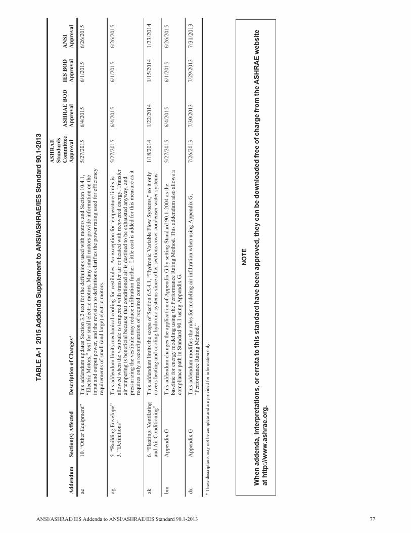
ae10
.“O
ther
Equ
ipm
ent”
Thi
sad
dend
umup
date
sSe
ctio
n3.
2te
xtfo
rth
ede
fini
tions
used
with
mot
ors
and
Sect
ion
10.4
.1,
“Ele
ctri
cM
otor
s,”
text
for
smal
lele
ctri
cm
otor
s.M
any
smal
lmot
ors
prov
ide
info
rmat
ion
onth
ein
puta
ndou
tput
pow
er,a
ndth
ere
visi
onto
defi
nitio
nscl
arif
ies
the
pow
erra
ting
used
for
effi
cien
cyre
quir
emen
tsof
smal
l(an
dla
rge)
elec
tric
mot
ors.
5/27
/201
56/
4/20
156/
1/20
156/
26/2
015
ag5.
“Bui
ldin
gE
nvel
ope”
3.“D
efin
ition
s”T
his
adde
ndum
limits
mec
hani
calc
oolin
gfo
rve
stib
ules
.An
exce
ptio
nfo
rte
mpe
ratu
relim
itsis
allo
wed
whe
nth
eve
stib
ule
iste
mpe
red
with
tran
sfer
air
orhe
ated
with
reco
vere
den
ergy
.Tra
nsfe
rai
rte
mpe
ring
isbe
nefi
cial
beca
use
that
cond
ition
edai
ris
dest
ined
tobe
exha
uste
dan
yway
,and
pres
suri
zing
the
vest
ibul
em
ayre
duce
infi
ltrat
ion
furt
her.
Litt
leco
stis
adde
dfo
rth
ism
easu
reas
itre
quir
eson
lya
reco
nfig
urat
ion
ofre
quir
edco
ntro
ls.
5/27
/201
56/
4/20
156/
1/20
156/
26/2
015
ak6.
“Hea
ting,
Ven
tilat
ing
and
Air
Con
ditio
ning
”T
his
adde
ndum
limits
the
scop
eof
Sect
ion
6.5.
4.1,
“Hyd
roni
cV
aria
ble
Flow
Syst
ems,
”so
iton
lyco
vers
heat
ing
and
cool
ing
hydr
onic
syst
ems
sinc
eot
her
sect
ions
cove
rco
nden
ser
wat
ersy
stem
s.1/
18/2
014
1/22
/201
41/
15/2
014
1/23
/201
4
bmA
ppen
dix
GT
his
adde
ndum
chan
ges
the
appl
icat
ion
ofA
ppen
dix
Gby
setti
ngSt
anda
rd90
.1-2
004
asth
eba
selin
efo
ren
ergy
mod
elin
gus
ing
the
Perf
orm
ance
Rat
ing
Met
hod.
Thi
sad
dend
umal
soal
low
sa
com
plia
nce
path
inSt
anda
rd90
.1us
ing
App
endi
xG
.
5/27
/201
56/
4/20
156/
1/20
156/
26/2
015
dxA
ppen
dix
GT
his
adde
ndum
mod
ifie
sth
eru
les
for
mod
elin
gai
rin
filtr
atio
nw
hen
usin
gA
ppen
dix
G,
“Per
form
ance
Rat
ing
Met
hod.
”7/
26/2
013
7/30
/201
37/
29/2
013
7/31
/201
3
TAB
LEA
-120
15A
dden
daS
uppl
emen
tto
AN
SI/A
SH
RA
E/IE
SS
tand
ard
90.1
-201
3
Add
endu
mSe
ctio
n(s)
Aff
ecte
dD
escr
ipti
onof
Cha
nges
*
ASH
RA
ESt
anda
rds
Com
mit
tee
App
rova
lA
SHR
AE
BO
DA
ppro
val
IES
BO
DA
ppro
val
AN
SIA
ppro
val
*T
hese
desc
ript
ions
may
notb
eco
mpl
ete
and
are
prov
ided
for
info
rmat
ion
only
.
NO
TE
Wh
en
ad
den
da,in
terp
reta
tio
ns,o
rerr
ata
toth
issta
nd
ard
have
been
ap
pro
ved
,th
ey
can
be
do
wn
load
ed
free
of
ch
arg
efr
om
the
AS
HR
AE
web
sit
e
at
htt
p:/
/ww
w.a
sh
rae.o
rg.
ANSI/ASHRAE/IES Addenda to ANSI/ASHRAE/IES Standard 90.1-2013 77

POLICY STATEMENT DEFINING ASHRAE’S CONCERNFOR THE ENVIRONMENTAL IMPACT OF ITS ACTIVITIES
ASHRAE is concerned with the impact of its members’ activities on both the indoor and outdoor environment. ASHRAE’s members will strive to minimize any possible deleterious effect on the indoor and outdoor environment of the systems and components in their responsibility while maximizing the beneficial effects these systems provide, consistent with accepted Standards and the practical state of the art.
ASHRAE’s short-range goal is to ensure that the systems and components within its scope do not impact the indoor and outdoor environment to a greater extent than specified by the Standards and Guidelines as established by itself and other responsible bodies.
As an ongoing goal, ASHRAE will, through its Standards Committee and extensive Technical Committee structure, continue to generate up-to-date Standards and Guidelines where appropriate and adopt, recommend, and promote those new and revised Standards developed by other responsible organizations.
Through its Handbook, appropriate chapters will contain up-to-date Standards and design considerations as the material is systematically revised.
ASHRAE will take the lead with respect to dissemination of environmental information of its primary interest and will seek out and disseminate information from other responsible organizations that is pertinent, as guides to updating Standards and Guidelines.
The effects of the design and selection of equipment and systems will be considered within the scope of the system’s intended use and expected misuse. The disposal of hazardous materials, if any, will also be considered.
ASHRAE’s primary concern for environmental impact will be at the site where equipment within ASHRAE’s scope operates. However, energy source selection and the possible environmental impact due to the energy source and energy transportation will be considered where possible. Recommendations concerning energy source selection should be made by its members.
ASHRAE · 1791 Tullie Circle NE · Atlanta, GA 30329 · www.ashrae.org
About ASHRAEASHRAE, founded in 1894, is a global society advancing human well-being through sustainable technology for thebuilt environment. The Society and its members focus on building systems, energy efficiency, indoor air quality,refrigeration, and sustainability. Through research, Standards writing, publishing, certification and continuingeducation, ASHRAE shapes tomorrow’s built environment today.
For more information or to become a member of ASHRAE, visit www.ashrae.org.
To stay current with this and other ASHRAE Standards and Guidelines, visit www.ashrae.org/standards.
Visit the ASHRAE Bookstore
ASHRAE offers its Standards and Guidelines in print, as immediately downloadable PDFs, on CD-ROM, and viaASHRAE Digital Collections, which provides online access with automatic updates as well as historical versions ofpublications. Selected Standards and Guidelines are also offered in redline versions that indicate the changes madebetween the active Standard or Guideline and its previous version. For more information, visit the Standards andGuidelines section of the ASHRAE Bookstore at www.ashrae.org/bookstore.
IMPORTANT NOTICES ABOUT THIS STANDARD
To ensure that you have all of the approved addenda, errata, and interpretations for thisStandard, visit www.ashrae.org/standards to download them free of charge.
Addenda, errata, and interpretations for ASHRAE Standards and Guidelines are no longerdistributed with copies of the Standards and Guidelines. ASHRAE provides these addenda,errata, and interpretations only in electronic form to promote more sustainable use ofresources.
3/16