Embed Size (px)
Citation preview

1
Annual Meeting of the Association of State Dam Safety Officials
Sept 9 to 13, 2001
Snowbird, UT
INNOVATIVE SLURRY TRENCH METHODS FOR THE REHABILITATION OF SMALL DAMS
Steven R. Day 1, Christopher R. Ryan 2, and Gary Fisk 3
Abstract
The rehabilitation of small dams often requires the reduction or control of groundwater seepage through or under earthen dams. The slurry trench method is well known for creating impermeable groundwater barriers and has been used for decades to create economical and positive cutoff walls in the core or foundation soils beneath dams and dikes of many types and sizes. This paper examines three innovative modifications of the slurry trench method and their applications in the rehabilitation of three small dams. Case histories of each dam and slurry trench method are described.
The slurry trench technique uses an engineered fluid for support of trench walls. Usually the fluid is bentonite slurry that coats the trench walls and permanently blocks the free flow of water. If, however, the fluid is degradable, a permeable backfill, such as sand or gravel can be backfilled in the trench to create a permeable zone such as a toe drain or chimney drain. This method is known as the bio-polymer trench drain method and has been used for more than a decade in the waste remediation industry to collect contaminated groundwater, and more recently in the rehabilitation of dams. A case study is presented of a small dam in Oregon that was rehabilitated with a toe drain constructed by the bio-polymer trench method.
Most slurry walls are backfilled with a mixture of soil and bentonite that provides an impermeable, but non-structural barrier. In some cases, a material with moderate structural strength is desirable, especially, for small dams under loads imposed by earthquakes or higher operating levels. A mixture of soil, cement and bentonite (SCB) has recently seen increasing acceptance. SCB is stronger and more impermeable than cement-bentonite grout, but flexible enough to allow for deformation, and usually less costly. A case study is presented of a small dam in Pennsylvania that used SCB for the core of the dam.
The slurry trench method can be used as an economical excavation method for removing boulders and obstacles with minimal excavation and maximum economy. A case study is presented of a small diversion dam in New Mexico where the slurry trench method
1 Vice President, Geo-Solutions, Denver, CO, Affiliate Member 2 President, Geo-Solutions, Pittsburgh, PA 3 Project Engineer, US Bureau of Reclamation, Denver, CO

2
was used to install steel sheetpiles in a riverbed where conventional pile driving was impossible due to the presence of boulders and cobbles.
Introduction
There are approximately 75,000 dams in the United States that provide flood protection,
water supply, power generation, irrigation, navigation, and recreation. Approximately, 30% of these dams are over 50 years old. Many of these dams were built using methods and materials that are now considered substandard. About 2100 of the operating dams in the United States are considered “unsafe”. In the past few years there have been over 200 dam failures that caused millions of dollars in damage and deaths1. It is imperative that dams, as a critical part of our country’s infrastructure, are made safe. In a time of limited resources the methods used to rehabilitate dams must be long lasting, positive and low in cost.
Slurry trenches are one of the most versatile and effective means for permanently controlling groundwater flow and thus the stability of dams. The design and construction of slurry trenches requires special expertise, but they are still a remarkable bargain in the civil engineering marketplace. The unit price of slurry trenches ($/sf) today is approximately the same as it was in 1970, without correction for inflation. The continuing low cost of slurry trenches is a result of increased productivity, innovation and competition in the market place.
The slurry trench method has been in use in the United States for at least 50 years. Previously, there were only three common varieties of the slurry trench method: 1) soil-bentonite (SB) slurry cutoff wall, 2) cement-bentonite (CB) slurry cutoff wall, and 3) concrete diaphragm wall for structural applications. Today, there are other cutoff techniques and new methods but slurry trenches remain among the least costly, most widely applied and, in many cases, the most positive method to create underground barriers, structures, and trench drains.
This paper presents cases studies of three small dams that were constructed or rehabilitated with slurry trenches. These case studies have been selected to show the range of potential slurry wall applications, construction methods, conditions, and costs under which they are installed. This paper will discuss three types slurry trenches: 1) bio-polymer trench drains, 2) soil-cement-bentonite (SCB) slurry cutoff walls, and 3) slurry trench excavation to install steel sheetpiles. These were all public works projects that were designed and overseen by government agencies. Tremendous progress has been made in the last few years in recognizing the utility of the slurry trench technique. Slurry walls are increasingly common on projects of all types.
Bio-Polymer Trench Drain at Wasco Dam Background
Wasco Dam is located on Clear Creek near the outlet of Clear Lake, a natural lake, 14 miles south of Mt. Hood and 90 miles east of Portland, OR. The dam is owned by U.S. Bureau of Reclamation (Reclamation) and is operated and maintained by the Juniper Flat District

3
Improvement Company (District), Maupin, Oregon. Project water is used to irrigate farmland in the Tygh Valley area, about 33 river miles downstream of Wasco Dam. Clear Lake has become a popular recreation destination for Portland and adjacent areas. The active storage capacity of the dam is 11,900 acre-ft at elevation 3526 feet2.
The dam was built in 1959 with a zoned embankment and a structural height of 51 feet and a crest length of 417 feet. The embankment consists of a silty clay core flanked on both sides with shell materials of sand, gravel, cobbles and boulders. An upstream cutoff trench was incorporated into the original design, extending through a sedimentary zone and into the fractured andesite foundation. The andesite bedrock was not grouted, and no internal chimney filter or drain was provided downstream of the core, as is now standard Reclamation practice. The cross-sections of the original embankment design and the current modifications are shown in Figure 1.
Figure 1: Cross-Section of Wasco Dam
Since its construction, the reservoir rarely fills to its normal pool elevation and the
spillway has never been used due to significant seepage through the dam. In 1996 heavy precipitation caused the reservoir to fill to the normal maximum pool for the first time in twenty years, creating significant seepage through the dam and giving urgency to dam safety concerns. At all reservoir levels the ground surface was at the toe of the dam was saturated, and at reservoir levels within 10 ft below the normal pool elevation, seepage occurred on the downstream face of the embankment.
Due to the excessive seepage, Reclamation and the District restricted the reservoir level to prevent the occurrence of unfiltered seepage. However, after only one season operating under a reservoir restriction the District decided that the irrigation water was too valuable and repairs to the dam were necessary. The most viable of the repair alternates was to construct a filter and toe drain 3 ft wide, 250 ft long and up to 20 ft deep. After a cost and a constructability review, it was decided that the quickest and least costly method to construct the trench was the bio-polymer slurry trench method3. Bio-Polymer Slurry Trench Drain
The bio-polymer slurry trench method is a technique that used degradable slurry instead of bentonite to retain the trench walls and control groundwater during construction. Slurry

4
trench construction eliminates the need for dewatering and shoring. After the trench is backfilled, injecting a “breaker” chemical degrades the slurry. The function of the slurry is to impose the slurry shear strength (viscosity) and density on the trench walls to exert hydrostatic pressure and thus preclude caving during excavation. To achieve the hydrostatic pressure required to keep the trench open, the trench is kept full of slurry at all times. The polymer slurry does not form a filter cake on the trench walls like bentonite but rather a gelatin-type coating that binds together individual soil particles on the trench wall. A modified polyacrylamide drilling fluid can be used as degradable slurry. Polyacrylamide is inherently safe and degrades to salt, lime and water with the addition of a mild hypochlorite (bleach) solution. This breaker solution is circulated through the backfill several times (through well points) until the effluent is similar in viscosity, appearance and chemical composition to water.
The new toe drain for Wasco Dam was constructed in the fall of 1999. The general contractor hired a slurry trench technical assistance firm to supervise the construction and quality control. Construction equipment consisted of a portable slurry mixer, slurry storage tank, tremie hopper, wheel loader, and two hydraulic excavators. Water for slurry was pumped to the slurry mixer from the reservoir. Polyacrylamide was mixed with water in the slurry mixer and stored in a frac tank until needed in the trench. The excavation began the day after the arrival of the equipment, and was completed in seven calendar days. One excavator was used to dig the trench and the second excavator was used to place the sand backfill into the trench through the tremie. The wheel loader transported sand backfill to the trench and removed trench spoil. The trench was maintained full of slurry at all times, which required close coordination of the slurry mixer with the excavation and backfill operations.
The slurry trench was constructed in four sections (or panels); one about 150 ft long across the toe and three shorter panels extending up the right groin. The excavation encountered sand, gravel, cobbles and boulders. The slurry was very effective in retaining the trench walls. A picture of the construction is shown in Figure 2. Slurry trench excavation was more difficult and slower on the sloped surface proceeding up the right groin. A series of three stepped benches (or work platforms) were constructed to level the trench alignment and permit the use of slurry up the sloping groin. Placing a sand filter in the groin with slurry excavation resulted in much less excavation into the embankment than would have occurred with traditional mass excavation.
The sand was placed in the trench with a tremie that minimized the drop height. The
tremie minimized the potential for segregation and low density pockets of sand. There was no evidence of low-density pockets or segregation. Pumping of the hypochlorite solution used to degrade the polyacrylamide caused settlements observed to be 4 to 6 inches at the surface that probably consolidated any low-density pockets.
The success of the filter and drain modification was shown by: 1) the dry ground at the
toe of the dam and elimination of seepage on the downstream face (caused by a lowering of the phreatic surface, 2) the lack of sand or fines deposited in the sediment trap in the inspection well, i.e., the filter prevented piping of materials, and 3) the piezometer readings showing that the filter was not raising the phreatic surface behind the filter, i.e., the filter was sufficiently permeable. In addition, the foundation filter below the toe drain provided filtration where observation was not possible.

5
Figure 2: Bio-Polymer Trench Drain Construction
SCB Slurry Wall at Brookville Dam Background
The Brookville Dam is located on North Fork of Redbank Creek near the City of Brookville, PA about 100 miles northeast of Pittsburgh, PA. The dam is owned by the city of Brookville and operated by the City Water Department. Project water is used as potable water for the residents of Brookville. The storage capacity of the dam is 513 acre-ft at maximum pool elevation4.
The dam was built in 1912 with earthen and concrete sections. The concrete section extends from the east abutment about 150 ft were it meets the earthen section that extends about 260 ft to the west abutment. The concrete section supports the spillway. The original dam was built with a structural height of 20 feet, which was raised 4.2 ft in the rehabilitation. The original design of the dam is not known and the original construction conditions of the dam are not well documented. The embankment of the earthen section was found to be alluvium and colluvium. The dam rests on sandstone and claystone bedrock. The cross-sections of the original embankment design and the current modifications are shown in Figure 3.

6
Figure 3: Cross-Section of Brookville Dam
In 2000, the City decided to upgrade and improve the safety of the dam and increase storage capacity. Improvements included covering the upstream face of the dam with RCC (roller compacted concrete), a concrete over-flow sill on the earthen section, and a deep cutoff wall. The concrete over-flow sill was located directly over the cutoff wall, so a cement-bentonite wall was specified to provide foundation support for the over-flow sill. The cutoff wall was designed to be 3 ft wide, 300 ft long and up to 30 ft deep. The cement-bentonite (CB) material was specified to have a minimum unconfined strength of 15 psi and a maximum hydraulic conductivity of 1 x 10⁻⁶ cm/sec5.
The general contractor’s slurry trench technical assistance subcontractor proposed to substitute a soil-cement-bentonite (SCB) slurry wall in lieu of the specified CB slurry wall because there was evidence that a standard CB mix could not attain the desired permeability requirements. The SCB wall offers better material properties than standard cement-bentonite. SCB construction creates much less spoil for disposal since the spoil can be reused in the SCB backfill. SCB Slurry Wall Construction
An SCB slurry wall is constructed in much the same manner as other conventional slurry cutoff walls6. A narrow trench is excavated under bentonite slurry, usually with a hydraulic excavator. The excavation is completed to the final trench depth while the trench is full of bentonite slurry. The slurry and hydrostatic pressure exert an outward pressure to keep the walls of the trench from collapsing. Once the excavation of the trench has progressed to some point clear of the starting point, the trench is backfilled with a blended mixture of soil (primarily trench spoil), bentonite slurry, dry bentonite and cement. The backfilling procedure is very similar to that used for soil-bentonite slurry wall construction, with a slope of backfill

7
being formed and allowed to flow into the trench so that the toe of the slope is close to, but not interfering with the excavation process. The SCB backfill is mixed and placed in carefully controlled batches and placed without delay to avoid premature hardening. A picture of SCB construction is shown in figure 4.
Figure 4: SCB Construction at Brookville Dam
At the Brookville Dam, the slurry wall was constructed through the center of the dam from the concrete spillway to the west abutment. The construction equipment included a hydraulic excavator, slurry mixing plant, and a wheel loader with fork attachment. The surface of the dam was prepared by removing riprap and leveling the trench alignment to form the work platform. The trench began at the existing concrete spillway. A connection was made to the spillway by scraping the vertical surface of the concrete spillway with the excavator bucket while working under bentonite slurry. The trench was excavated from the spillway toward the west embankment. SCB backfill was blended inside a 25 ft by 25 ft enclosure formed by concrete ‘jersey barriers’. The excavator placed a measured volume of soil inside the enclosure where measured amounts of dry bentonite powder and cement grout were added to the soil. The ingredients were mixed together with bentonite slurry by repeated stirring and kneading with the excavator, until the material appeared homogeneous with a slump of 3 to 6 inches. The loader then carried the SCB to the trench and placed it from the top of the slope into the trench. Excavation was followed by backfilling until the trench was complete. Excess bentonite slurry displaced when the backfill was completed was mixed with drier soils and spread out to dry.

8
The SCB slurry wall provided a successful installation. Portions of the slurry wall were
excavated for the over-flow sill and the wall appeared homogeneous and without defects. The SCB supported the concrete sill without difficulty and settlement has not been observed. Groundwater flow through the dam was noticeably reduced after the construction of the slurry wall, as evidenced by a general drying and stabilization of the downstream toe.
Sheetpile/Slurry Trench at Hogback Diversion Dam
Background
The Hogback Diversion Dam is located on the San Juan River near Shiprock, New Mexico, about 17 miles west of Farmington, New Mexico on Navajo Indian Tribal Lands. The dam stands in the shadow of a massive hogback rock formation, thus the name. The dam was constructed by the Bureau of Reclamation with funding appropriated for the Navajo Indian Irrigation Project. Project water is used for agricultural irrigation. The dam is intended to divert water into the irrigation system during periods of low water flow, and to provide a more reliable river habitat for the protection of native fish species. The dam is not intended to create a permanent reservoir.
The embankment of the earthen section was found to be alluvium and colluvium. Prior to the year 2000 improvements, a concrete diversion structure (weir, trash rack, log boom, etc.) had been built into the north bank of the river (circa 1968) to direct water into the irrigation canal. Natural variations in the river level created periods when water could not reach the diversion structure. River flows vary from 2500 cfs to a nearly dry riverbed. Temporary methods were employed by the Irrigation Project to divert water by building dikes in the river with river sediments. These temporary dikes had to be re-built several times each year and had unintended detrimental side effects on water and habitat quality7.
Figure 5: Cross-Section of Hogback Diversion Dam
The permanent diversion dam has an embankment that has a structural height of ten
feet and a crest length of 1110 ft. The embankment consists of an earthen core and a riprap shell. Downstream training dikes were also built. The dam rests on sand, cobbles and boulder river sediments, which overlies sandstone bedrock. A cross-section of the embankment is shown in Figure 5.
9
Sheetpile Installation in Slurry Trench A partial cutoff wall (“hanging barrier”) was designed for the dam to provide dam
stability, retard river flows and allow water diversion. A hanging barrier is a cutoff wall that leaves a gap between the bottom of the barrier and the top of the bedrock to permit a controlled groundwater flow under the barrier. At high groundwater velocities, the potential exists at the bottom of the barrier for erosion or scour so usually a structural material is specified for the barrier. Originally, steel sheetpiles seemed to be a logical choice for the hanging barrier, however, it was later discovered that the riverbed was the site of numerous buried boulders and cobbles that would make conventional sheetpile installation impossible.
The designers came up with a resourceful method for overcoming the boulder-laden riverbed and using surplus steel sheetpiles. The usual method for installing sheetpiles in a slurry trench uses CB slurry so the sheetpiles can be dropped into place, in the middle of the trench before the CB sets up. The hardening of the CB holds the sheetpiles permanently in place. Non-structural materials (e.g. HDPE) can also be placed in soil-bentonite or bio-polymer slurry trenches but these materials are usually placed against one trench wall for support. At Hogback dam, environmental concerns (presence of endangered fish) precluded the use of cement in the river, so a modified installation method was required. The construction plans specified a bentonite slurry-supported trench with steel sheetpiles installed in the center of the trench. The trench was specified to be backfilled with cobbles and other native materials to help hold the sheetpiles in place.
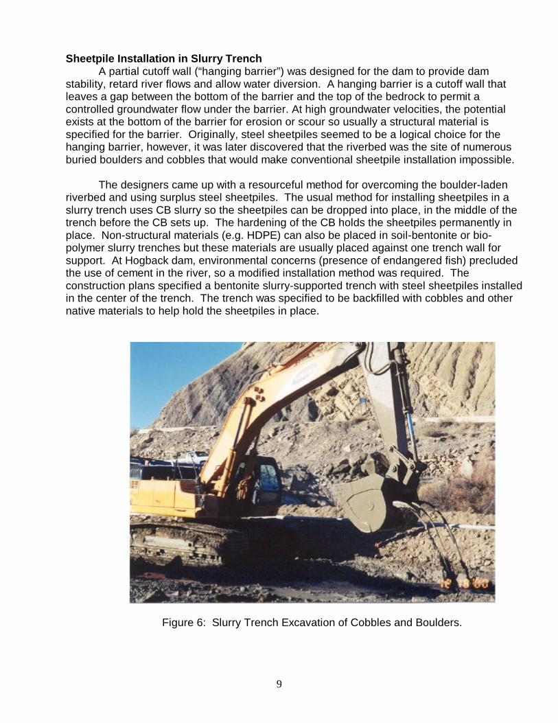
Figure 6: Slurry Trench Excavation of Cobbles and Boulders.

10
The contractor’s slurry trench technical assistance subcontractor proposed an alternate installation method that was accepted by Reclamation. The slurry trench specialist recognized that extraordinary methods would be required to keep the sheetpiles in the proper alignment if the trench was backfilled with cobbles. Furthermore, there was no practical method of holding the bottom of the sheetpile in the middle of the trench at the bottom of slurry filled trench. Instead, the contractor excavated the slurry trench first, removed the boulders, and then backfilled the trench with sand (minus 3 inch screened materials). The sand was wet and would not consolidate for a few days. Before the sand could consolidate, the sheetpiles were driven into place with a light weight (600 pound) vibratory hammer. This small hammer could install a sheetpile through the loose sand in a few seconds. Later, dry sand was used as the backfill to minimize the consolidation period.
The slurry trench excavation was successful in removing the boulders and clearing a path for the sheet pile installation. A hydraulic excavator dug the trench while a second excavator backfilled. Large boulders (up to 6 ft), cobbles, wire cable, and sand were excavated from the trench. The work was completed in December and often in freezing temperatures. A picture of the slurry trench excavation of cobbles and boulders is shown in figure 6.
Figure 7: Installation of Steel Sheetpiles in Slurry Trench
The specifications required the sheetpiles be placed with less than 0.25 inch of lateral displacement per vertical foot (about 2%). This verticality standard would probably be difficult with conventional pile driving. In order to maintain this extraordinary verticality, a template was placed on the surface to hold the sheetpile in place while a small crane with a vibratory

11
hammer drove the sheetpile through the soft slurry wall backfill. The template was modified several times in an effort to increase production. After some trial and error, the best method found for holding the sheets involved using a piece of equipment (loader or excavator) instead of a template as a temporary support. For added support, every tenth sheet was driven to refusal to better hold the sheets in place. This method was so successful that up to 200 lf of sheetpiles 15 to 20 ft long could be installed in a single shift. A view of the sheetpile installation in the completed slurry trench is shown in figure 7.
The sheetpile installation was finished a few days after the slurry trench was backfilled. There was minimal consolidation of the slurry trench. The installation was completed during a period of low water, which ended with an unexpected flood shortly after the installation was completed. The sheetpiles maintained their alignment allowing the remaining work to proceed without delay. The installation price for the sheetpiles was actually less (and more productive) than the typical price for sheetpiles installation with conventional pile driving equipment in virgin ground.
Summary
Slurry trenches of all kinds have achieved wide acceptance in a variety of applications in the construction and rehabilitation of small dams. Besides the conventional soil-bentonite, cement-bentonite, and concrete slurry walls; there are also bio-polymer trench drains, soil-cement-bentonite walls, and slurry trenches used for excavation purposes. Slurry trenches can be used to create non-structural groundwater barriers, structural walls with a wide range of available strengths, hanging barriers, and trench drains.
The design for a slurry wall should be flexible enough to allow for contractor innovation. Knowledgeable technical assistance is available from specialty firms to solve practical installation problems on most projects. Specifications should take into account built-in safety factors inherent in slurry walls (for example, more thickness is usually provided by excavating equipment than needed by most designs); and allow for both normal variability and permit some additional variability when complications arise from working under difficult underground conditions.
Slurry trench have the potential to rehabilitate and improve many of our country’s substandard dams at a cost that is often much lower than conventional competing methods. As the public becomes more aware of the need to fix our aging and substandard dams, it seems likely that slurry trenches will play an increasing role in improving the safety of dams.
References 1. Association of State Dam Safety Officials, “National Dam Safety Program”, www.damsafety.org, June 2001. 2. Contract Documents for Wasco Dam Modifications, Wapinitta Project, Oregon, United States Department of the Interior, Bureau of Reclamation, Pacific Northwest Division. 1999.

12
3. Fisk, G., Gagliardi, J., and Day, S.R., “Slurry Trench Construction of a Vertical Foundation Filter at Wasco Dam”, US International Congress on Large Dams Annual Conference, Denver, CO., July 2000. 4. Bruhn, B., Personal Communication, GAI Consultants, Monroeville, PA. 2001, June 2001. 5. Contract Documents for Brookville Dam, Brookville, PA, Brookville Municipal Authority, Brookville, PA. 1999.
6. Ryan, C.R., “Vertical Barriers in Soil for Pollution Containment,” American Society of Civil Engineers Specialty Conference, Ann Arbor, MI, June 1987. 7. Contract Documents for the Hogback Diversion Dam, Hogback Project, New Mexico, United States Department of the Interior, Bureau of Reclamation, Upper Colorado Region, Salt Lake City, UT, 2000.