Embed Size (px)
Citation preview
The National Dam Safety Program Research Needs Workshop:Seepage through Embankment Dams

Preface One of the activities authorized by the Dam Safety and Security Act of 2002 is research to enhance the Nation’s ability to assure that adequate dam safety programs and practices are in place throughout the United States. The Act of 2002 states that the Director of the Federal Emergency Management Agency (FEMA), in cooperation with the National Dam Safety Review Board (Review Board), shall carry out a program of technical and archival research to develop and support:
• improved techniques, historical experience, and equipment for rapid and effective dam construction, rehabilitation, and inspection;
• devices for continued monitoring of the safety of dams; • development and maintenance of information resources systems needed to
support managing the safety of dams; and • initiatives to guide the formulation of effective policy and advance improvements
in dam safety engineering, security, and management. With the funding authorized by the Congress, the goal of the Review Board and the Dam Safety Research Work Group (Work Group) is to encourage research in those areas expected to make significant contributions to improving the safety and security of dams throughout the United States. The Work Group (formerly the Research Subcommittee of the Interagency Committee on Dam Safety) met initially in February 1998. To identify and prioritize research needs, the Subcommittee sponsored a workshop on Research Needs in Dam Safety in Washington D.C. in April 1999. Representatives of state and federal agencies, academia, and private industry attended the workshop. Seventeen broad area topics related to the research needs of the dam safety community were identified. To more fully develop the research needs identified, the Research Subcommittee subsequently sponsored a series of nine workshops. Each workshop addressed a broad research topic (listed below) identified in the initial workshop. Experts attending the workshops included international representatives as well as representatives of state, federal, and private organizations within the United States.
• Impacts of Plants and Animals on Earthen Dams • Risk Assessment for Dams • Spillway Gates • Seepage through Embankment Dams • Embankment Dam Failure Analysis • Hydrologic Issues for Dams • Dam Spillways • Seismic Issues for Dams • Dam Outlet Works
In April 2003, the Work Group developed a 5-year Strategic Plan that prioritizes research needs based on the results of the research workshops. The 5-year Strategic Plan ensures that priority will be given to those projects that demonstrate a high degree of

collaboration and expertise, and the likelihood of producing products that will contribute to the safety of dams in the United States. As part of the Strategic Plan, the Work Group developed criteria for evaluating the research needs identified in the research workshops. Scoring criteria was broken down into three broad evaluation areas: value, technical scope, and product. The framework adopted by the Work Group involved the use of a “decision quadrant” to enable the National Dam Safety Program to move research along to produce easily developed, timely, and useful products in the near-term and to develop more difficult, but useful, research over a 5-year timeframe. The decision quadrant format also makes it possible to revisit research each year and to revise research priorities based on current needs and knowledge gained from ongoing research and other developments. Based on the research workshops, research topics have been proposed and pursued. Several topics have progressed to products of use to the dam safety community, such as technical manuals and guidelines. For future research, it is the goal of the Work Group to expand dam safety research to other institutions and professionals performing research in this field. The proceedings from the research workshops present a comprehensive and detailed discussion and analysis of the research topics addressed by the experts participating in the workshops. The participants at all of the research workshops are to be commended for their diligent and highly professional efforts on behalf of the National Dam Safety Program.
Acknowledgments The National Dam Safety Program research needs workshop on Seepage through Embankment Dams was held on October 17-19, 2000, in Denver, Colorado. The Department of Homeland Security, Federal Emergency Management Agency, would like to acknowledge the contributions of the Association of State Dam Safety Officials and URS Corporation in organizing the workshop and developing these workshop proceedings. A complete list of workshop facilitators, presenters, and participants is included in the proceedings.
TABLE OF CONTENTS
REPORT OF WORKSHOP ON ISSUES, SOLUTIONS AND RESEARCH NEEDS RELATED TO SEEPAGE THROUGH EMBANKMENT DAMS
vii List of Abbreviations
1.0 Introduction and Scope of Report
2.0 Executive Summary
3.0 Workshop Process
4.0 Workshop Results for Individual Topics
4.1 Topic 1 - Potential Seepage Problems and Solutions Associated with Penetrations 4.1.1 through Embankment Dams (e.g., Outlet Works Conduits)
4.1.1 State-of-the-Practice White Paper
4.1.2 State-of-the-Practice Refinement
4.1.3 Prioritization of Research and Development Ideas
4.1.4 Preliminary Research and Development Plans
4.2 Topic 2 - Filter Design Criteria and Observed Performance (The Concepts of No Erosion and Continuous Erosion Boundaries for Evaluating Filter Compatibility) and Mechanism of Particle Movement and Progression of Internal Erosion
4.2.1 State-of-the-Practice White Paper
4.2.2 State-of-the-Practice Refinement
4.2.3 Prioritization of Research and Development Ideas
4.2.4 Preliminary Research and Development Plans
4.3 Topic 3 - Inspection of Dams for Detection of Seepage Problems, Failure Modes Associated with Seepage and Internal Erosion, and Analysis of Risks Associated with Seepage and Internal Erosion
4.3.1 State-of-the-Practice White Paper
4.3.2 State-of-the-Practice Refinement
4.3.3 Prioritization of Research and Development Ideas
4.3.4 Preliminary Research and Development Plans
4.4 Topic 4 - Investigation of Seepage Problems/Concerns at Dams, Including the Use of Geophysical Techniques; and Instrumentation and Measurements for Evaluation of Seepage Performance
4.4.1 State-of-the-Practice White Paper
4.4.2 State-of-the-Practice Refinement
4.4.3 Prioritization of Research and Development Ideas
I
TABLE OF CONTENTS
4.4.4 Preliminary Research and Development Plans
4.5 Topic 5 - Remediation of Seepage Problems through Cutoff or Reduction of Flow and Through Collection and Control of Seepage (Including the Use of Geosynthetics)
4.5.1 State-of-the-Practice White Paper
4.5.2 State-of-the-Practice Refinement
4.5.3 Prioritization of Research and Development Ideas
4.5.4 Preliminary Research and Development Plans
4.6 Topic 6 - Impacts of Aging of Seepage Control/Collection System Components on Seepage Performance
4.6.1 State-of-the-Practice White Paper
4.6.2 State-of-the-Practice Refinement
4.6.3 Prioritization of Research and Development Ideas
4.6.4 Preliminary Research and Development Plans
5.0 Overall Prioritization of Research and Development Ideas
6.0 References
II
TABLE OF CONTENTS
EXHIBITS Exhibit 3-1 ASDSO Seepage Advisory Committee and FEMA Project Officer
Exhibit 3-2 Workshop Particip ants
Exhibit 3-3 Summary of Survey/Questionnaire Responses
Exhibit 3-4 Topics Selected for the Workshop
Exhibit 3-5 White Paper Authors and Titles
Exhibit 4-1 Prioritization of Research and Development Ideas –
Workshop Topic 1 - Potential Seepage Problems and Solutions Associated with Penetrations through Embankment Dams (e.g. Outlet Works Conduits)
Exhibit 4-2 Research and Development Implementation Plan, R&D Topic 1A – Compilation of Case Histories of Seepage Incidents Related to Penetrations through Embankment Dams
Exhibit 4-3 Research and Development Implementation Plan, R&D Topic 1B – Assessing Technology to Detect Voids and Concentrated Seepage around Penetrations through Embankment Dams
Exhibit 4-4 Research and Development Implementation Plan, R&D Topic 1C – Develop Guidelines for Design of Filter Diaphragms Associated with Conduits through Embankment Dams
Exhibit 4-5 Research and Development Implementation Plan, R&D Topic 1D – Guidelines for Inspecting, Monitoring, and Detecting Seepage along Penetrations through Embankment Dams
Exhibit 4-6 Research and Development Implementation Plan, R&D Topic 1E – Development and Deployment of Guidelines for Slip-lining of Outlet Works Conduits
Exhibit 4-7 Prioritization of Research and Development Ideas –
Workshop Topic 2 - Filter Design Criteria and Observed Performance (The Concepts of No Erosion And Continuous Erosion Boundaries for Evaluating Filter Compatibility) And Mechanism of Particle Movement And Progression of Internal Erosion
Exhibit 4-8 Research and Development Implementation Plan, R&D Topic 2A – Classification of Conditions Conducive to Hydraulic Fracturing and Cracking
Exhibit 4-9 Research and Development Implementation Plan, R&D Topic 2B – Develop State-of-the-Practice for Configurations, Dimensions, and Construction Methods for Filters and Drains
Exhibit 4-10 Research and Development Implementation Plan, R&D Topic 2C – Evaluate Mechanism of Piping and Failure in Glacial, Alluvial, and Fluvial Environments – Including Consideration of Internal Instability
III
TABLE OF CONTENTS
Exhibit 4-11 Research and Development Implementation Plan, R&D Topic 2D – Evaluation of Mechanical/Geochemical Degradation of Properties of Filter Materials, Including Cementation and the Ability to Sustain a Crack
Exhibit 4-12 Research and Development Implementation Plan, R&D Topic 2E – Threshold Gradients for Initiating Piping in Cohesive Soils
Exhibit 4-13 Prioritization of Research and Development Ideas –
Workshop Topic 3 - Inspection of Dams for Detection of Seepage Problems, Failure Modes Associated with Seepage and Internal Erosion, and Analysis of Risks Associated with Seepage and Internal Erosion
Exhibit 4-14 Research and Development Implementation Plan, R&D Topic 3A – Enhancement of Academic Programs and Professional Development Programs Related to Seepage Issues in Dam Design and Rehabilitation – “Certification” of Dam Designers, Dam Construction Inspectors, and Dam Operators
Exhibit 4-15 Research and Development Implementation Plan, R&D Topic 3B – Develop Guidance for Dam Surveillance Plans Relative to Seepage
Exhibit 4-16 Research and Development Implementation Plan, R&D Topic 3C – Improve Failure Time Estimates for Seepage-Related Failure Modes for Existing Dams
Exhibit 4-17 Research and Development Implementation Plan, R&D Topic 3D – Identify Factors for Failure for a) “First Filling” (Including Normally Dry Dams/Detention Dams, Maximum Pool, etc.) and b) Long Term, for Each Seepage-Related Failure Mode
Exhibit 4-18 Research and Development Implementation Plan, R&D Topic 3E – Expand the Database of Information on Seepage/Piping Failures/Incidents for Dams <15 meters in Height
Exhibit 4-19 Prioritization of Research and Development Ideas –
Workshop Topic 4 – Investigation of Seepage Problems/Concerns at Dams, Including the Use of Geophysical Techniques; and Instrumentation and Measurements for Evaluation of Seepage Performance
Exhibit 4-20 Research and Development Implementation Plan, R&D Topic 4A – Technology Transfer of Geophysical Techniques for Seepage Monitoring
Exhibit 4-21 Research and Development Implementation Plan, Topic 4B – Test Capabilities of Different Geophysical Methods on a Test Embankment
Exhibit 4-22 Research and Development Implementation Plan, R&D Topic 4C – Cross-Discipline Technology Transfer for Investigative Techniques in Dams
IV
TABLE OF CONTENTS
Exhibit 4-23 Research and Development Implementation Plan, R&D Topic 4D – Do/Can Instruments or Instrument Installations Cause Damage in Embankment Dams
Exhibit 4-24 Research and Development Implementation Plan, R&D Topic 4E – Assess Photo-Monitoring Techniques for Seepage (Infrared Imaging, Photo Interpretation, etc.)
Exhibit 4-25 Prioritization of Research and Development Ideas –
Workshop Topic 5 – Remediation of Seepage Problems through Cutoff or Reduction of Flow and Through Collection and Control of Seepage (Including the Use of Geosynthetics)
Exhibit 4-26 Research and Development Implementation Plan, R&D Topic 5A – Review of Performance of Seepage Remediation Measures: a) Upstream Cutoff Only, b) Upstream Cutoff with Downstream Collection, and c) Downstream Collection Only
Exhibit 4-27 Research and Development Implementation Plan, R&D Topic 5B – Compilation of Practices, Applications, Experiences, Economics, and Advantages/Disadvantages of Using Geotextiles in Dam Applications
Exhibit 4-28 Research and Development Implementation Plan, R&D Topic 5C – Evaluate the Performance of In-Place Geotextiles in Seepage Control Applications
Exhibit 4-29 Research and Development Implementation Plan, R&D Topic 5D – Develop Design Criteria for Drainage Pipe Openings and Surrounding Material to Prevent Plugging
Exhibit 4-30 Research and Development Implementation Plan, R&D Topic 5E – Testing of Fabric Clogging Under Steady State Flow Properly Simulating Conditions in Dam Applications
Exhibit 4-31 Prioritization of Research and Development Ideas –
Workshop Topic 6 – Impacts of Aging of Seepage Control/Collection System Components on Seepage Performance
Exhibit 4-32 Research and Development Implementation Plan, R&D Topic 6A Research and Develop Techniques for Remediation and Prevention of Contamination of Wells, Drains, and Instrumentation
Exhibit 4-33 Research and Development Implementation Plan, R&D Topic 6B – Criteria for Frequency of Inspections and Rehabilitation of Horizontal Drains, Including Removal of Carbonates
Exhibit 4-34 Research and Development Implementation Plan, R&D Topic 6C – Research Methods to Control and/or Remove Iron Bacteria Deposits from Wells and Drain Systems
Exhibit 4-35 Research and Development Implementation Plan, R&D Topic 6D – Develop Test Criteria and Procedures for Evaluating Site Vulnerability to Physical/Chemical/Biological Deterioration of Seepage Collection and Control Systems
V
TABLE OF CONTENTS
Exhibit 5-1 Ranking of Research/Development Ideas Based on Overall Votes at the Workshop
Exhibit 5-2 Ranking of Research/Development Ideas Based on Overall Votes after the Workshop
Exhibit 5-3 Ranking of Research/Development Ideas Based on Individual Scores for Potential Benefit – Scores Given By Participants after the Workshop
Exhibit 5-4 Ranking of Research/Development Ideas Based on Individual Scores for Probability of Success – Scores Given By Participants after the Workshop
Exhibit 5-5 Ranking of Research/Development Ideas Based on Individual Scores for Cost – Scores Given By Participants after the Workshop
Exhibit 5-6 Ranking of Research/Development Ideas Based on Combination of Individual Scores for Potential Benefit, Probability of Success, and Cost
Exhibit 5-7 Best Estimates of Implementation Costs for Research/Development Ideas Based on Input from Workshop Participants
Exhibit 5-8 Comparison and Combination of Overall Rankings and Combination of Individual Scores
VI
TABLE OF CONTENTS
ATTACHMENTS
Attachment 1 Pre-Workshop Questionnaire
Attachment 2 Additional Comments in Response to the Pre-Workshop Questionnaire
Attachment 3 Survey Forms Sent to Participants after the Workshop
Attachment 4 White Paper No. 1 - Potential Seepage Problems and Solutions Associated with Penetrations through Embankment Dams, Joseph R. Kula
Attachment 5 White Paper No. 2 - The Internal Erosion and Piping Process, by Robin Fell and Mark Foster
Attachment 6 White Paper No. 3 - Assessing The Risk of a Seepage-Related Dam Failure by Means of Failure Mode Identification, Risk Analysis, and Monitoring Practices, by William O. Engemoen
Attachment 7 White Paper No. 4 - Investigation Of Seepage Problems/Concerns at Dams, Including Use of Geophysical Techniques; and Instrumentation and Measurements for Evaluation of Seepage Performance, by Charles D. Wagner
Attachment 8 White Paper No. 5 - Remediation of Seepage Problems through Cutoff or Reduction of Flow and through Collection and Control of Seepage Including the Use of Geosynthetics, by James R. Talbot, Steve J. Poulos, and Ronald C. Hirschfeld
Attachment 9 White Paper No. 6 - The Impacts of Aging of Seepage Control/Collection System Components on Seepage Performance, by Danny K. McCook
Attachment 10 Participants’ Estimates of Implementation Costs for Research and Development Ideas
Attachment 11 Reference List
REPORT OF WORKSHOP ON ISSUES, SOLUTIONS AND RESEARCH NEEDS RELATED TO SEEPAGE THROUGH EMBANKMENT DAMS
VII
TABLE OF CONTENTS
LIST OF ABBREVIATIONS
Abbreviation Definition
ADS............................Advanced Drainage Systems A/E.............................Architect/engineer ASCE .........................American Society of Civil Engineers ASDSO ......................Association of State Dam Safety Officials ASTM.........................American Society for Testing of Materials BC ..............................British Columbia CANCOLD ................Canadian Committee on Large Dams Cc ...............................Coefficient of curvature (for soil grain size curve) CEA............................Canadian Electric Association CFR............................Comprehensive Facility Review (USBR) CMP...........................Corrugated metal pipe CPTu...........................Piezocone penetration test Cu ...............................Coefficient of uniformity (for soil grain size curve) DEA ...........................U.S. Drug Enforcement Agency FEMA.........................Federal Energy Management Agency FERC..........................Federal Energy Regulatory Agency GRI.............................Geosynthetics Research Institute HDPE.........................High-density polyethylene ICODS .......................Interagency Committee on Dam Safety ICOLD .......................International Committee on Large Dams IFA.............................International Fabrics Association JPL .............................Jet Propulsion Laboratory MS..............................Master of Science NPDP .........................National Performance of Dams Program NRCS.........................Natural Resources Conservation Service (formerly SCS) NSF............................National Science Foundation OSHA.........................Occupational Safety and Health Administration PhD.............................Doctor of Philosophy R&D...........................Research and development SCS ............................Soil Conservation Service (now NRCS) SPT.............................Standard penetration test TADS .........................Training Aids for Dam Safety TEC ............................Topographic Engineering Center TVA ...........................Tennessee Valley Authority UNSW........................University of New South Wales USACE.......................U.S. Army Corps of Engineers USBR.........................U.S. Bureau of Reclamation USCOLD....................U.S. Committee on Large Dams (now USSD) USGS .........................U.S. Geological Survey USSD .........................United States Society on Dams (formerly USCOLD)
VIII
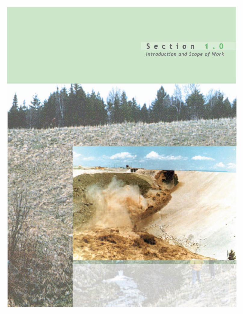
1.0 INTRODUCTION
INTRODUCTION AND SCOPE OF REPORT
This workshop is part of a series of workshops being sponsored by the Federal Emergency Management Agency (FEMA) and administered by the Association of State Dam Safety Officials (ASDSO). This workshop was organized and facilitated by URS Corporation, under contract with ASDSO, and under the guidance of the ASDSO Seepage Advisory Committee. The product of the workshop is this written report, produced by URS and ASDSO, documenting the results of the workshop. The report will be included in FEMA’s National Dam Safety Program Act Report Series.
The workshop consisted of convening and facilitating a group of experts with respect to dam safety issues associated with seepage through embankments and their foundations. The objectives of the workshop and the resulting written report were to document:
1. The state-of-practice, as opposed to state-of-the-art, concerning seepage and internal erosion of embankment dams and foundations;
2. The short-term (immediate) and long-term research needs of the Federal and non-Federal dam safety communities with respect to this issue; and
3. A recommended course of action for the Federal and non-Federal dam safety communities to address these needs based on priorities relating to potential benefit, probability of success, and cost.
The workshop was held in Denver, Colorado, on October 17, 18, and 19, 2000. The workshop was a successful undertaking that produced open communication among a wide range of experts in the field and identified research and development opportunities that could significantly improve the state-of-the-practice in the field.
IMPORTANCE OF THE TOPIC
The importance of consideration of seepage through embankment dams is highlighted by some statistics from a recent research program at the University of New South Wales, Australia. Professor Robin Fell and two of his graduate students, Mark Foster and Matt Spannagle, reviewed records for more than 11,000 large (higher than 15 meter) embankment dams. They found:
• 136 or 1.2 percent of these dams had failed, with failure defined as an uncontrolled release of the reservoir;
• of the failures, 59, or about 44 percent, were caused by seepage and piping;
• another 1.5 percent of the dams were reported to have experienced some type of piping incident that did not lead to failure; and
• although failure statistics appear to be better for modern dams (those constructed since 1950), the failure rate is still about 0.5 percent, with seepage and piping still being a common failure mode, in fact the percentage of failures attributable to seepage and piping for the modern dams was 52 percent, higher that that for the pre-1950 dams.
It should be noted that these statistics are based on the information reported in the available records, and it is certainly likely that there are seepage incidents, and possibly even failures, that have not been reported.
These sobering statistics clearly indicate that improvement in the understanding of seepage and piping should be a significant concern of all modern dam engineers.
1-1
2.0 EXECUTIVE SUMMARY
2.0 EXECUTIVE SUMMARY
A group of 35 individuals was assembled for a three-day workshop on Issues, Solutions, and Research Needs Related to Seepage Through Embankment Dams. The group consisted of 27 invited experts, two facilitators, five members of the ASDSO Seepage Advisory Committee, and the FEMA Project Officer for the workshop. The workshop participants were selected to provide broad representation of individuals involved in the topic. Participants included 13 representatives of six different U.S. federal agencies, four representatives from three different state dam safety agencies, 12 representatives of eight different consulting companies, three independent consultants, two university professors, and one representative of a hydropower organization. The group included individuals from 15 different U.S. states and two other countries (Canada and Australia).
During the three days, the workshop participants addressed the following six topics:
1. Potential seepage problems and solutions associated with penetrations through embankment dams (e.g., outlet works conduits).
2. Filter design criteria and observed performance (the concepts of no erosion and continuous erosion boundaries for evaluating filter compatibility) and mechanism of particle movement and progression of internal erosion.
3. Inspection of dams for detection of seepage problems, failure modes associated with seepage and internal erosion, and analysis of risks associated with seepage and internal erosion.
4. Investigation of seepage problems/concerns at dams, including the use of geophysical techniques; and instrumentation and measurements for evaluation of seepage performance.
5. Remediation of seepage problems through cutoff or reduction of flow and through collection and control of seepage (including the use of geosynthetics).
6. Impacts of aging of seepage control/collection system components on seepage performance.
These specific topics were selected based the results of a survey of the participants that was completed in advance of the workshop.
Each topic was treated in the following manner:
• A “strawman” state-of-the-practice white paper was prepared and presented by one or more of the invited experts; a written copy of the white paper was distributed to the participants in advance of the workshop.
• The entire group was then led in a facilitated discussion of refinements, modifications, and clarifications to the state-of-the-practice.
• The group developed a list of possible research and development ideas for the topic being considered.
• The possible research and development ideas were prioritized by the group considering potential benefit, probability of success, and cost.
• The top four or five research and development ideas for the topic were assigned to small work groups for development of preliminary implementation plans.
2-1
2.0 EXECUTIVE SUMMARY• The small work groups reported back to the entire group on their preliminary
implementation plans.
The “strawmen” state-of-the-practice white papers are presented in Attachments 4 through 9 of this report, and brief summaries of these papers are presented in Section 4. The discussions of the states-of-the-practice for the six topics are summarized in Section 4 of this report, and some of the more significant points from those discussions are presented later in this Executive Summary. All of the research and development ideas generated by the group for all six topics are presented in Section 4, and the preliminary implementation plans developed for the 29 leading ideas generated for all six topics are also presented in Section 4.
In a closing session on the last day of the workshop and in surveys completed after the workshop, the participants provided input for an overall ranking of the leading research and development ideas for all six topics. The overall rankings were also based on consideration of potential benefit, probability of success, and cost. The overall rankings of the leading research and development ideas are discussed in detail in Section 5 and are summarized later in this Executive Summary.
STATE-OF-THE-PRACTICE
During the state-of-the-practice white paper presentations and the ensuing discussions, it became apparent that it is very difficult, if not impossible, to define a single state-of-the-practice for any of the topics being considered. The state-of-the-practice in the area of seepage through embankment dams varies from region-to-region and organization-to-organization. Consequently, much of the discussion centered on trying to develop consensus among the group of invited experts on what the state-of-the-practice should be for certain aspects of practice. All of the discussions on state-of-the-practice are documented in Section 4, but some of the more significant results of the discussions, in the authors’ opinion, are the following, grouped according to the six topics addressed in the workshop:
PROBLEMS AND SOLUTIONS ASSOCIATED WITH PENETRATIONS THROUGH EMBANKMENT DAMS
1. There was a general, but not unanimous, consensus that sand (or sand and gravel) filter diaphragms around conduits are preferred over concrete cutoff collars for controlling seepage and piping along the sides of outlet works conduits.
2. The existing NRCS/SCS conduit filter diaphragm design criteria were developed for 18 to 48 inch diameter pipes. There are no widely available criteria for larger pipes.
3. Grouting around conduits is not recommended as a sole solution for prevention of piping. Grouting will not likely provide 100 percent encapsulation of the conduit and seepage gradients in the “windows” in the grout may actually be higher than the initial gradients before grouting. Grouting can be used to fill or partially fill voids created by piping, to reduce future settlements, but filter diaphragms or other positive means must be used to prevent piping.
4. Bare (unencased) corrugated metal outlet conduits should not be used for new construction or replacements in significant or high hazard dams. Although many existing dams include bare corrugated metal outlet conduits, their generally poor long-term performance argues strongly against their continued use. In addition, studies have shown that corrugated metal pipe outlet conduits are inferior to concrete pipe outlet conduits, when evaluated on a life-cycle-cost basis.
2-2
2.0 EXECUTIVE SUMMARY5. There was a general, but not unanimous, consensus that the springline is the
recommended minimum height for the top of a conduit cradle, if a cradle is used.
6. There was consensus that permanently pressurized pipes through embankments should be either encased (e.g., in concrete) or placed within an outer conduit.
FILTER DESIGN CRITERIA, OBSERVED PERFORMANCE, AND MECHANISM OF PARTICLE MOVEMENT AND PROGRESSION OF INTERNAL EROSION
1. There has been some valuable recent research at the University of New South Wales extending previous work on filter design criteria to consideration of “continuous erosion boundaries” – the gradation boundaries between “filter” materials that allow some limited degree of particle movement but then stabilize and those that allow particles in the base material to move continuously. These continuous erosion boundaries should not be applied to design of new dams or designs of new dam rehabilitation features, for which the established filter design criteria should be used. However, the continuous erosion boundaries may be useful in evaluating the risks of piping in existing structures that were not designed or constructed strictly according to current filter criteria.
2. At present there remains a lack of understanding of the mechanics of piping on the particle level. Such an understanding would help to tie laboratory and field observations together into a common understanding of the piping phenomenon.
3. Filters constructed of soil materials should not be over-compacted. In current practice soil filter materials are often compacted to a greater degree than necessary. Over-compaction of filter materials can result in reduced permeability and increased potential for the filter materials to be capable of holding an open crack. Soil filter materials should be compacted only to the degree necessary for strength and settlement requirements. It was the consensus of the participants that 90 percent of modified Proctor compaction (or 65 to 70 percent relative density) would be sufficient in almost all cases.
4. After extensive discussion, a general consensus was reached that piping can often be an episodic phenomenon. That is, piping with muddy or turbid seepage may occur for some period of time, after which the pipe collapses or stabilizes for some period of time, only to be followed later by another episode of active piping. It may take many repeated episodes of piping before the phenomenon progresses to failure of the dam. The importance of this understanding of the piping phenomenon is that the observation of clear seepage does not necessarily mean that there is no piping problem. It could simply be the case that the observation was made during a period of no active piping. Piping should be considered a possibility for any case of uncontrolled seepage. Inspectors should also look for evidence of past piping episodes (e.g., silt or sand deposits at or downstream of seepage exit points).
5. It was a group consensus that the effectiveness of “crack fillers” or “crack-stoppers” is unknown – they may or may not be effective.
6. For design of new structures, it is the state-of-the-practice to assume that fine-grained embankment materials crack.
INSPECTION, FAILURE MODES, AND ANALYSIS OF RISK
1. There are currently two different approaches to quantitative risk analysis for seepage through embankment dams. They can be broadly categorized as 1) the statistical-based method, and 2) the degree-of-belief-based method. The general consensus is that the
2-3
2.0 EXECUTIVE SUMMARYdegree-of-belief-based method is presently considered to be the state-of-the-practice for risk analysis for seepage through dams, and this will probably remain so for the foreseeable future. At the workshop, the BC Hydro representative requested that it be specifically noted that his organization does not presently support the use of detailed quantitative risk analysis (with either approach) for dam seepage issues. The reader is referred to the report of the March 2000, Logan, Utah Workshop on Risk Analysis for Dams for a more extensive treatment of this topic. The results of that workshop are presented in another report in FEMA’s National Dam Safety Program Act Report Series.
2. The qualifications, training, and experience of dam inspectors and operators are highly variable in the United States. Yet the qualifications, training, and experience of these individuals are critical to professional judgments that must be made in operating and maintaining a dam.
INVESTIGATION OF SEEPAGE PROBLEMS/CONCERNS
1. Although actual investigation practices vary widely, it was the consensus of the workshop participants that the recommended state-of-the-practice should be that drilling should not be done in the core of an existing embankment dam unless absolutely necessary, and then only with carefully planned precautions and dry drilling (e.g., auger) methods. The risk of hydraulic fracturing is too great to support drilling in the core without appropriate justification.
2. It was the consensus of the workshop participants that drilling or test pitting should not be done at the downstream toe of a dam with water stored in the reservoir, without contingency plans and stockpiling of weighted filter materials (e.g., sand and gravel) to be used in the event of a seepage incident. It is also essential that such explorations be completed with the on-site presence of experienced personnel with the knowledge to react appropriately to any seepage incidents that may occur.
3. It was the consensus of the workshop participants that they generally advised against installing piezometers in an embankment core, unless there were very compelling reasons for the instruments. The workshop participants felt that, in most cases, piezometers in the core do not provide significant additional understanding of the performance of the dam beyond that which can be obtained from piezometers in the upstream and downstream shells, which are much safer locations for the instruments.
4. Piezometers are tools whose careful installation and subsequent data interpretation, in conjunction with other investigative techniques, may provide valuable information in diagnosing seepage conditions. However, the limitations of what the piezometers record must be recognized, and the piezometer data must be used in conjunction with other information (e.g., seepage rates, seepage locations, etc.) to correctly diagnose seepage conditions. Since piping channels in embankments are often relatively long, narrow features, it is not likely that piezometers will be located at exactly the correct locations to provide direct data regarding the piping phenomenon.
5. The dam engineering profession in general remains skeptical or cautious regarding the effectiveness of geophysical techniques for investigation of seepage problems, possibly because the methods are perceived as not proven sufficiently to establish a high degree of confidence. There have been some successful applications of geophysical methods, and some of the methods show promise. Successful applications will likely increase in the future through research efforts such as those of the Canadian Electric Association.
2-4
2.0 EXECUTIVE SUMMARYREMEDIATION OF SEEPAGE PROBLEMS
1. Although in current practice cutoffs are being used as a sole solution for seepage/piping problems, the consensus of the workshop group supports the position that cutoffs should always be used together with adequate downstream collection and control systems. What constitutes an adequate collection and control system for use in combination with a cutoff is subject to engineering judgment.
2. Seepage collection pipes in blanket drains under downstream shells of dams are being used – the potential disadvantages (collapse, plugging, drilling into them) of this application should be recognized when they are used.
3. The current practice for the use of geotextiles in seepage collection systems varies widely among organizations and practitioners involved in dam engineering. After much discussion, it was the consensus of the group that a) geotextiles should not be used in locations that are both critical to safety and inaccessible for replacement, and b) geotextiles can be used in locations that are critical for safety but accessible for replacement. However, in the second case the engineer must assess the potential hazard posed by failure of the geotextile and the time available to respond and repair or replace the geotextile. This position may change in the future based on development of data on long-term, in-place performance of geotextiles in dam applications.
4. Several participants related experience with poor performance with the rate of inflow into slotted or perforated pipes when the sizes of the openings in the pipes and the gradations of the surrounding soil filters were designed according to currently recommended guidelines. It appears that the soil particles can partially to substantially plug the openings, resulting in limited inflow. This appears to be less of a problem with pipes surrounded by gravel than it is for pipes surrounded by sand or sand/gravel mixtures.
5. It was the consensus of the workshop participants that the recommended state-of-the-practice for application of pressure grouting (cement or chemical) in seepage remediation should be that a) high-pressure grouting should never be used in the embankment core and b) high-pressure grouting is acceptable in rock foundations, with appropriate care. However, it was the experience of the group that grouting was often not a permanent solution.
IMPACTS OF AGING OF SYSTEM COMPONENTS
1. Regular and thorough maintenance is essential to the continued effectiveness of relief wells.
2. There are reported cases of long-term deterioration of grout curtains.
3. There is some anecdotal information in the profession indicating that some filters may have altered over time so that they could hold an open crack after alteration.
4. It was the consensus of the group that corrugated metal pipes should not be used for drain pipes in seepage collection systems, because of their record of deterioration.
RESEARCH AND DEVELOPMENT IDEAS
Before the research and development ideas were ranked, some of the 29 separate ideas generated for the six different topics addressed in the workshop were combined to reduce the total number of research and development (R&D) topics to 26.
2-5
2.0 EXECUTIVE SUMMARYBased on all of the input from the participants, it is the authors opinion that the following four R&D topics were the leading research and development ideas identified in the workshop:
1. Expand the Database of Information on Seepage/Piping Failures/Incidents for Dams <15 meters in Height, and Compile Case Histories of Seepage Incidents Related to Penetrations Through Embankment Dams (R&D Topic 3E &1A)
2. Enhance Academic Programs and Professional Development and Training Programs Related to Seepage Issues in Dam Design and Rehabilitation – “Certification” of Dam Designers, Dam Construction Inspectors, and Dam Operators (R&D Topic 3A)
3. Develop State-of-the-Practice for Configurations, Dimensions, and Construction Methods for Filters and Drains (R&D Topic 2B)
4. Develop Guidelines for Design of Filter Diaphragms Associated With Conduits Through Embankment Dams (R&D Topic 1C)
These four R&D topics were ranked in the top 10 in all three overall ranking methods used to prioritize the research and development ideas and they were ranked 1 through 4 when the rankings from the three different methods were averaged, as discussed in detail in Section 5. Consequently, it is the authors’ opinion that these four R&D topics are the highest priorities for implementation. The R&D topic designations given in parentheses after the research and development ideas are the designations assigned during the workshop and used in Sections 4 and 5 of this report. The preliminary implementation plans for the R&D topics are presented in Section 4 using those designations.
After the four R&D topics listed above, the remaining six ideas in the top 10, based on the average of the rankings from the three different methods, were:
1. Develop Design Criteria for Drainage Pipe Openings and Surrounding Material to Prevent Plugging (R&D Topic 5D)
2. Develop Guidance for Dam Surveillance Plans Relative to Seepage, Including Monitoring and Detecting Seepage Along Penetrations Through Embankment Dams (R&D Topic 3B & 1D)
3. Technology Transfer of Geophysical Techniques for Seepage Monitoring (R&D Topic 4A)
4. Evaluate Mechanism Of Piping And Failure In Glacial, Alluvial, And Fluvial Environments – Including Consideration Of Internal Instability, and Including Consideration of Threshold Gradients for Initiating Piping in Cohesive Soils (R&D Topic 2C & 2E)
5. Compilation of Practices, Applications, Experiences, Economics, and Advantages/Disadvantages of Using Geotextiles in Dam Applications (R&D Topic 5B)
6. Assess Technology to Detect Voids and Concentrated Seepage Around Penetrations Through Embankment Dams (R&D Topic 1B)
R&D Topic 5D was ranked in the top 10 according to all three methods used (Ranks of 10, 7, and 8), and the other five R&D topics were ranked in the top 10 in two out of the three methods used. Consequently, it is the authors’ opinion that these six R&D topics should be considered high priority, but not as high as the top four ideas listed above.
2-6
2.0 EXECUTIVE SUMMARYOther R&D topics that received a top 10 ranking in at least one of the three overall ranking methods used to prioritize the ideas were:
1. Evaluate the Performance of In-Place Geotextiles in Seepage Control Applications (R&D Topic 5C)
2. Testing of Fabric Clogging Under Steady State Flow Properly Simulating Conditions in Dam Applications (R&D Topic 5E)
3. Classification of Conditions Conducive to Hydraulic Fracturing and Cracking (R&D Topic 2A)
4. Review of Performance of Seepage Remediation Measures: a) Upstream Cutoff Only, b) Upstream Cutoff With Downstream Collection, and c) Downstream Collection Only (R&D Topic 5A)
5. Research Methods to Control and/or Remove Iron Bacteria Deposits From Wells and Drain Systems (R&D Topic 6C)
6. Development and Deployment of Guidelines for Slip-lining of Outlet Works Conduits (R&D Topic 1E)
These R&D topics deserve some consideration for implementation, but at a lower priority than the top 10 ideas listed above.
The remaining 10 R&D topics had significantly less support in the overall rankings of the ideas, with none of them ranked in the top 10 in any of the three ranking processes used.
Section 5 of the report provides some thoughts for possible further combinations of the identified R&D topics.
The participants were also asked to provide estimates of the cost of implementing each of the research and development ideas, if they felt qualified to do so. Unfortunately, only 11 participants felt qualified to provide cost information and the estimates provided varied widely. Consequently, the results are not particularly helpful, but they are provided in Section 5 and Attachment 10 of this report for completeness.
In reviewing the leading R&D topics, it is interesting to note that very few of them involve basic laboratory or field research. In fact, only R&D Topics 2E, 5D, 1B, 5E, 2A, and 6C include such basic research, and none of the top four topics include basic research. Rather, most of the R&D topics involve collecting or compiling available information and developing guidelines for dissemination to practitioners. In the authors’ opinion, this reflects a sense among the workshop participants that the overall topic of seepage through embankment dams is relatively mature, and that most seepage problems are the result of misuse of available information or lack of knowledge of available information by some practitioners. It also seems to reflect a feeling that the information on the overall topic is too dispersed for the profession to make the best use of lessons-learned from past performance, and that compilation of information into more readily available sources would be beneficial.
CLOSURE
The workshop provided a forum for lively and open discussion of important topics related to seepage through embankment dams. The discussions resulted in consensus among the invited experts on recommendations regarding a number of important, but controversial, aspects of the state-of-the-practice. Through the workshop effort, a relatively long list of possible research and development ideas was compiled, and that list was prioritized to identify what
2-7

2.0 EXECUTIVE SUMMARYthe group believed were the leading ideas for advancement of the state-of-the-practice. The group also developed preliminary implementation plans for 29 research and development ideas, and those plans are presented in Section 4 of this report.
2-8

3.0 WORKSHOP PROCESS
WORKSHOP PROCESS
This discussion of the workshop process is divided into the following three topics:
• Selection of Workshop Participants
• Selection of Workshop Topics
• Workshop Mechanics
SELECTION OF WORKSHOP PARTICIPANTS
The workshop participants were selected jointly by URS and the ASDSO Seepage Advisory Committee. Members of the ASDSO Seepage Advisory Committee and the FEMA Project Officer for the workshop are listed in Exhibit 3-1.
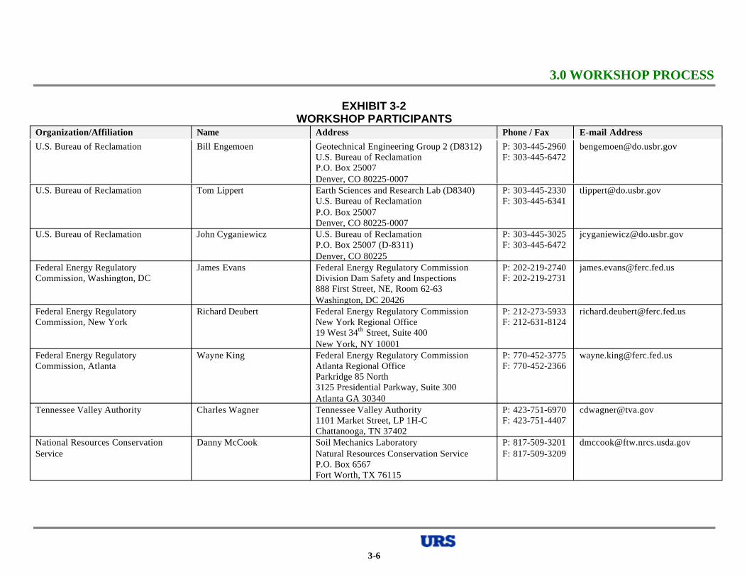
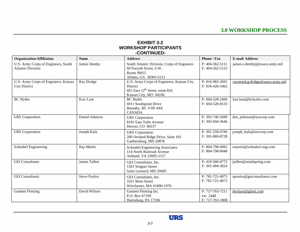
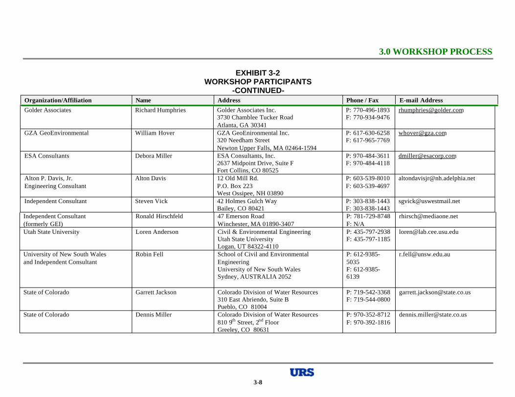
Participation in the workshop was by invitation only, and the workshop was not publicly advertised. The goal in selecting participants for invitation to the workshop was to have broad representation of public and private organizations and individuals involved in dam safety seepage issues. To keep the workshop to a manageable size, the number of invited experts was limited to 27. When combined with the two URS facilitators, five members of the ASDSO Seepage Advisory Committee, and the FEMA Project Officer, the total workshop group consisted of 35 individuals. The workshop participants are listed in Exhibit 3-2.
The workshop participants were a diverse group, including:
• 13 representatives of six different U.S. federal agencies;
• 4 representatives from three different state dam safety agencies;
• 12 representatives of eight different consulting companies;
• 3 independent consultants;
• 2 university professors;
• 1 representative of a hydropower organization; and
• Individuals from 15 different U.S. states and two other countries (Canada and Australia).
SELECTION OF WORKSHOP TOPICS
To accomplish as much as possible within the relatively short duration of the workshop, it was judged necessary to pre-select specific topics to be addressed. In pre-selecting the topics, it was desired to accomplish two at least partially conflicting goals to the maximum extent possible. Those goals were:
• To address what were judged to be the most important and pressing topics regarding seepage through embankment dams.
• To cover as much breadth as possible of topics related to seepage through embankment dams.
Considering the three-day duration of the workshop, it was judged that six topics, each being addressed for about one-half day, was the maximum number of topics that could be addressed in any reasonable depth. It was decided to use a survey of participants, and a few
3-1
3.0 WORKSHOP PROCESSother selected experts who were not available to participate, to develop the topics for the workshop.
URS worked with the ASDSO Seepage Advisory Committee to develop a list of 14 potential topics for the workshop. To narrow this list to six topics for the workshop, a survey/questionnaire was sent to potential participants. The questionnaire asked each individual to select up to eight topics that they thought should be the highest priority for consideration at the workshop. In the questionnaire each individual was also asked to list any other important topics that he or she believed were not addressed by the 14 listed topics. A copy of the questionnaire that was sent to the participants is included as Attachment 1 of this report.
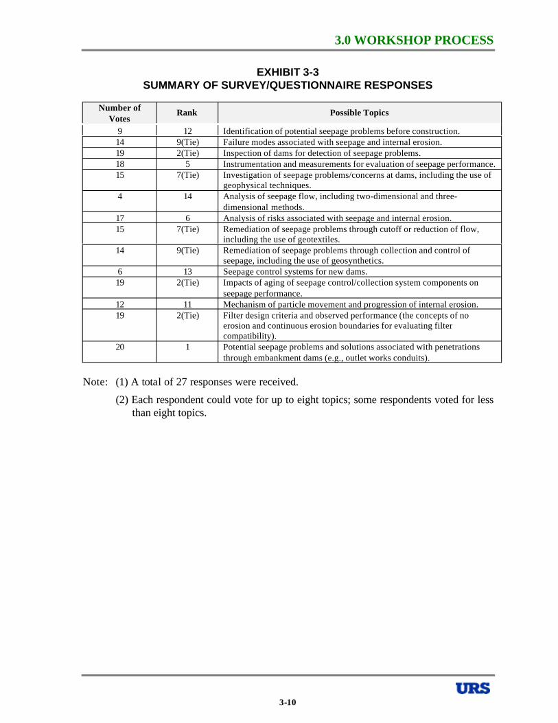
Twenty-seven individuals responded to the questionnaire and the results of their “votes” are presented in Exhibit 3-3. The “additional comments” received from the respondents are compiled in Attachment 2.
From a review of the responses, six topics were developed for coverage at the workshop. The six selected topics are presented in Exhibit 3-4. As noted above, the six topics were developed to meet the two stated objectives: 1) provide coverage of the highest priority items identified in the responses; and 2) provide as much breadth of coverage as possible within the three-day scope of the workshop.
WORKSHOP MECHANICS
The workshop was conducted over three full days, which were divided into six half-day periods, each addressing one of the six selected topics. The agenda for each of these six half-days was as follows:
• One-half to three-quarter hour - Presentation of a “State-of-the-Practice” white paper, prepared in advance by one of the participants.
• One-half to three-quarter hour – Facilitated discussion of the white paper by all participants, to identify revisions, modifications, and refinements to the “State-of-the-Practice” presented by the white paper author.
• One hour – Identification and prioritization of possible research and development ideas that could advance the state-of-the-practice.
• One hour – Development of preliminary implementation plans for the highest priority research and development ideas.
At the end of the third day, approximately 1-1/2 hours were devoted to comparing and prioritizing all of the “high-priority” research and development ideas that were developed for the six different topics. After the workshop had been adjourned, surveys were sent to all participants to gather additional input for the prioritization of the research and development ideas.
The discussions, research and development ideas, and preliminary research and development plans were captured on flipcharts during the workshop, for compilation in this report.
Some of the specific aspects of the workshop mechanics are discussed further below.
3-2
3.0 WORKSHOP PROCESS
WHITE PAPERS
After the six topics were selected, some of the workshop participants were invited to prepare “white papers” to provide documents that would be “strawmen” for definitions of state-of-the-practice relative to the six topics. The white paper authors were also invited to put forward suggestions for research and development ideas related to their topics, if they so desired, but their primary responsibility was to develop “strawmen” for the definition of the state-of-the-practice.
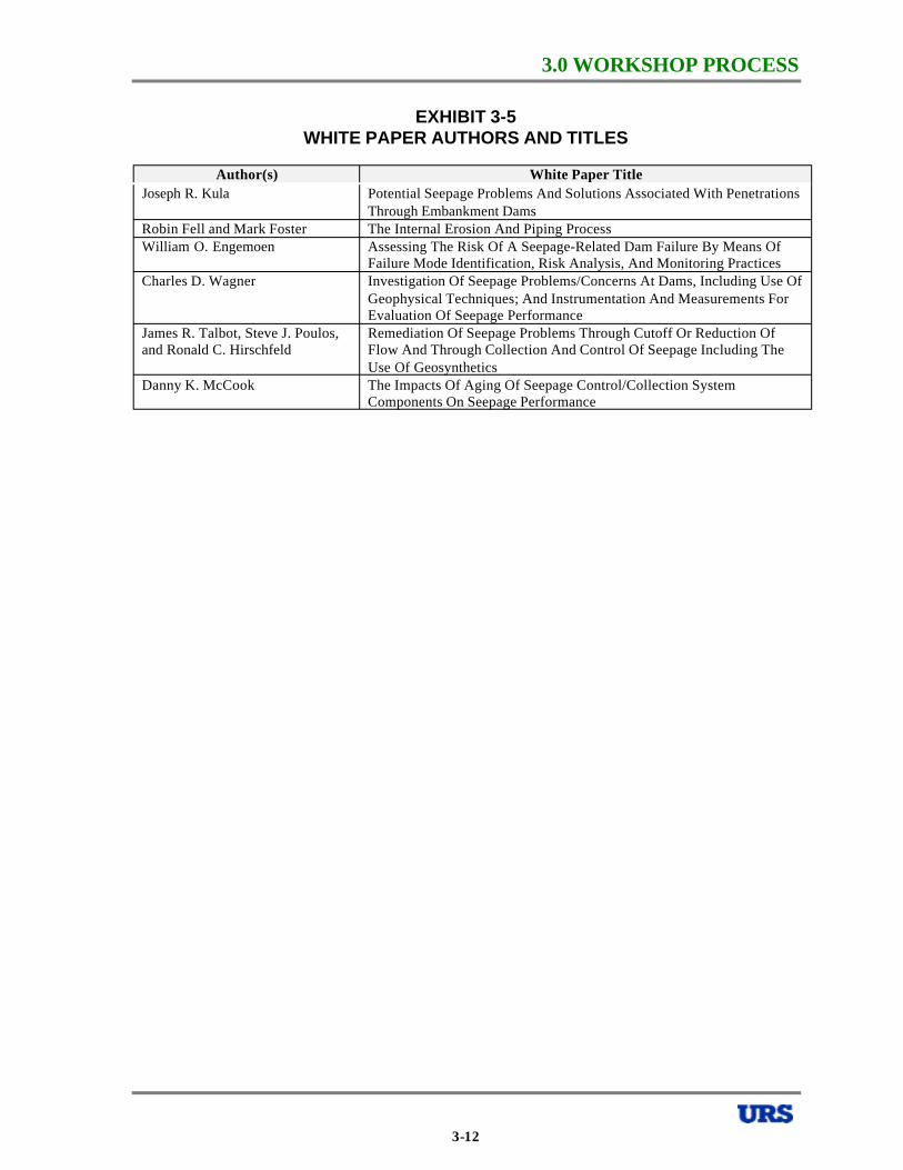
The authors all prepared their white papers for distribution to the participants in advance of the workshop. They are owed a debt of gratitude for their contribution to the success of the workshop. The white paper authors are all listed in the Exhibit 3-5, and the individual white papers are presented in Section 4 of this report.
DISCUSSIONS OF WHITE PAPERS
The revisions, modifications, and refinements to the white papers were captured on flipcharts during the workshop and are reported in Section 4 of this report. One thing that became apparent during the discussions was that “practice” in this field varies significantly from one state or region to another and from one agency or organization to another. This makes it very difficult to define a singular state-of-the-practice. Consequently, much of the discussion of the white papers and the state-of-the-practice consisted of identifying some of the more significant differences in practice and attempting to reach a consensus among the group on what the state-of-the-practice should be or to identify research and development required to determine the appropriate state-of-the-practice. This will become apparent in the discussions in Section 4.
IDENTIFICATION AND PRIORITIZATION OF RESEARCH AND DEVELOPMENT IDEAS
For each topic, the potential research and development ideas were compiled from a brainstorming process with the entire group. The ideas were listed on flipcharts visible to all participants. The research and development ideas for each topic were then prioritized in a simple voting process, in which each participant was given a fixed number of “stick-on dots” that they could place next to the individual ideas. The number of dots (votes) given to each participant was typically about N/3, where N is the total number of research and development ideas being considered. The participants were allowed to cast their votes however they saw fit; there were no limits on the number of votes that a participant could cast for a particular idea. A participant could cast all of his or her votes for one research and development idea, if he or she thought it was a high enough priority. Before they cast their votes, the participants were instructed to balance the following three criteria in prioritizing the research and development ideas: 1) potential benefit, 2) probability of success, and 3) cost.
All of the research and development ideas and the results of the prioritizations for all six topics are presented in Section 4 of this report.
PRELIMINARY IMPLEMENTATION PLANS
After the prioritization was completed, the top four or five ideas for each topic were selected for development of preliminary implementation plans. The workshop participants were divided into small work groups (about 7 or 8 people per group), and each work group was assigned the responsibility to develop a preliminary implementation plan for one research and development idea. The small groups worked independently for a period of time, and then
3-3
3.0 WORKSHOP PROCESS
all of the workshop participants reconvened to hear and discuss reports from all of the small work groups. The composition of the small work groups was shuffled for each topic, so that the same people were not working together all of the time. One workshop participant was assigned the responsibility to serve as the leader of each work group, and this responsibility was rotated among almost all participants over the course of the three days.
The implementation plans developed by the work groups are presented in Section 4 of this report.
OVERALL PRIORITIZATION OF RESEARCH AND DEVELOPMENT IDEAS
The initial overall prioritization of the 29 leading research and development ideas resulting from consideration of the six different topics was completed at the workshop using the same voting technique used for prioritizations for the six different topics. Again, participants were asked to consider the balance of potential benefit, probability of success, and cost in casting their prioritization votes, and, as before, the participants could cast their allotted votes in any way they saw fit. Before the prioritization votes were taken, some of the research and development ideas were combined, resulting in a reduction in the total number of ideas from 29 to 26.
At the end of the workshop, the participants suggested that they would like to have the opportunity to cast their prioritization votes again, after they had some time to think further about the information discussed at the workshop. Consequently, a survey was sent to all workshop participants asking them to provide further input for the prioritization process. The implementation plans developed by the small work groups were sent to the participants with the survey. The survey was structured so that 1) the participants repeated the voting process completed at the end of the workshop, casting votes considering the balance of potential benefit, probability of success, and cost, and 2) the participants provided separate scores for each of the three criteria for each of the research and development ideas. The participants were also asked to provide estimates of the cost of implementing each of the research and development ideas, if they felt qualified to do so. Unfortunately, only 11 participants felt qualified to provide cost information and the estimates provided varied widely. Consequently, the results are not particularly helpful, but they are provided in Section 5 and Attachment 10 of this report for completeness. The survey forms sent to the participants are presented in Attachment 3.
The prioritization of the 26 leading research and development ideas is discussed in detail in Section 5 of this report.
3-4
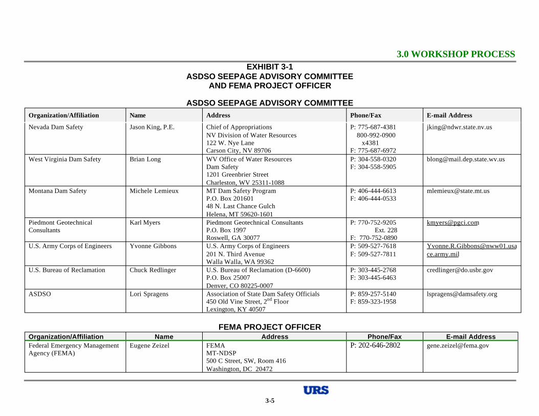
3.0 WORKSHOP PROCESSEXHIBIT 3-1
ASDSO SEEPAGE ADVISORY COMMITTEE AND FEMA PROJECT OFFICER
ASDSO SEEPAGE ADVISORY COMMITTEE Organization/Affiliation Name Address Phone/Fax E-mail Address
Nevada Dam Safety Jason King, P.E.
West Virginia Dam Safety Brian Long
Montana Dam Safety Michele Lemieux
Piedmont Geotechnical Karl Myers Consultants
U.S. Army Corps of Engineers Yvonne Gibbons
U.S. Bureau of Reclamation Chuck Redlinger
ASDSO Lori Spragens
Chief of Appropriations NV Division of Water Resources 122 W. Nye Lane Carson City, NV 89706 WV Office of Water Resources Dam Safety 1201 Greenbrier Street Charleston, WV 25311-1088 MT Dam Safety Program P.O. Box 201601 48 N. Last Chance Gulch Helena, MT 59620-1601 Piedmont Geotechnical Consultants P.O. Box 1997 Roswell, GA 30077 U.S. Army Corps of Engineers 201 N. Third Avenue Walla Walla, WA 99362 U.S. Bureau of Reclamation (D-6600) P.O. Box 25007 Denver, CO 80225-0007 Association of State Dam Safety Officials 450 Old Vine Street, 2nd Floor Lexington, KY 40507
FEMA PROJECT OFFICER
P: 775-687-4381800-992-0900
x4381 F: 775-687-6972 P: 304-558-0320 F: 304-558-5905
P: 406-444-6613 F: 406-444-0533
P: 770-752-9205 Ext. 228
F: 770-752-0890 P: 509-527-7618 F: 509-527-7811
P: 303-445-2768 F: 303-445-6463
P: 859-257-5140 F: 859-323-1958
[email protected] ce.army.mil
Organization/Affiliation Name Address Phone/Fax E-mail Address Federal Emergency Management Agency (FEMA)
Eugene Zeizel FEMA MT-NDSP 500 C Street, SW, Room 416
P: 202-646-2802 [email protected]
Washington, DC 20472
3-5
3.0 WORKSHOP PROCESS
EXHIBIT 3-2 WORKSHOP PARTICIPANTS
Organization/Affiliation Name Address Phone / Fax E-mail Address
U.S. Bureau of Reclamation Bill Engemoen Geotechnical Engineering Group 2 (D8312) P: 303-445-2960 [email protected] U.S. Bureau of Reclamation F: 303-445-6472 P.O. Box 25007 Denver, CO 80225-0007
U.S. Bureau of Reclamation Tom Lippert Earth Sciences and Research Lab (D8340) P: 303-445-2330 [email protected] U.S. Bureau of Reclamation F: 303-445-6341 P.O. Box 25007 Denver, CO 80225-0007
U.S. Bureau of Reclamation John Cyganiewicz U.S. Bureau of Reclamation P: 303-445-3025 [email protected] P.O. Box 25007 (D-8311) F: 303-445-6472 Denver, CO 80225
Federal Energy Regulatory James Evans Federal Energy Regulatory Commission P: 202-219-2740 [email protected] Commission, Washington, DC Division Dam Safety and Inspections F: 202-219-2731
888 First Street, NE, Room 62-63 Washington, DC 20426
Federal Energy Regulatory Richard Deubert Federal Energy Regulatory Commission P: 212-273-5933 [email protected] Commission, New York New York Regional Office
19 West 34th Street, Suite 400 F: 212-631-8124
New York, NY 10001 Federal Energy Regulatory Wayne King Federal Energy Regulatory Commission P: 770-452-3775 [email protected] Commission, Atlanta Atlanta Regional Office F: 770-452-2366
Parkridge 85 North 3125 Presidential Parkway, Suite 300 Atlanta GA 30340
Tennessee Valley Authority Charles Wagner Tennessee Valley Authority P: 423-751-6970 [email protected] 1101 Market Street, LP 1H-C F: 423-751-4407 Chattanooga, TN 37402
National Resources Conservation Danny McCook Soil Mechanics Laboratory P: 817-509-3201 [email protected] Service Natural Resources Conservation Service F: 817-509-3209
P.O. Box 6567 Fort Worth, TX 76115
3-6
3.0 WORKSHOP PROCESS
EXHIBIT 3-2 WORKSHOP PARTICIPANTS
-CONTINUED- Organization/Affiliation Name Address Phone / Fax E-mail Address U.S. Army Corps of Engineers, South James Demby South Atlantic Division, Corps of Engineers P: 404-562-5111 [email protected] Atlantic Division 60 Forsyth Street, S.W. F: 404-562-5122
Room 9M15 Atlanta, GA 30303-5111
U.S. Army Corps of Engineers, Kansas Ray Dridge U.S. Army Corps of Engineers, Kansas City P: 816-983-3691 [email protected] City District District
601 East 12th Street, room 816 F: 816-426-5462
Kansas City, MO 64106 BC Hydro Ken Lum BC Hydro P: 604-528-2406 [email protected]
6911 Southpoint Drive F: 604-528-8133 Burnaby, BC V3N 4X8 CANADA
URS Corporation Daniel Johnson URS Corporation P: 303-740-2689 [email protected] 8181 East Tufts Avenue F: 303-694-3646 Denver, CO 80237
URS Corporation Joseph Kula URS Corporation P: 301-258-9780 [email protected] 200 Orchard Ridge Drive, Suite 101 F: 301-869-8728 Gaithersburg, MD 20878
Schnabel Engineering Ray Martin Schnabel Engineering Associates 114 North Railroad Avenue
P: 804-798-0081 F: 804-798-0048
Ashland, VA 23005-1517
GEI Consultants James Talbot GEI Consultants, Inc. P: 410-586-8772 [email protected] 1301 Wagner Street F: 301-494-3824 Saint Leonard, MD 20685
GEI Consultants Steve Poulos GEI Consultants, Inc. P: 781-721-4075 [email protected] 1021 Main Street F: 781-721-4073 Winchester, MA 01890-1970
Gannett Fleming David Wilson Gannett Fleming Inc. P: 717-763-7211 [email protected] P.O. Box 67100 ext. 2448 Harrisburg, PA 17106 F: 717-763-1808
3-7
3.0 WORKSHOP PROCESS
EXHIBIT 3-2 WORKSHOP PARTICIPANTS
-CONTINUED- Organization/Affiliation Name Address Phone / Fax E-mail Address
Golder Associates Richard Humphries Golder Associates Inc. P: 770-496-1893 [email protected] 3730 Chamblee Tucker Road F: 770-934-9476 Atlanta, GA 30341
GZA GeoEnvironmental William Hover GZA GeoEnironmental Inc. P: 617-630-6258 [email protected] 320 Needham Street F: 617-965-7769 Newton Upper Falls, MA 02464-1594
ESA Consultants Debora Miller ESA Consultants, Inc. P: 970-484-3611 [email protected] 2637 Midpoint Drive, Suite F F: 970-484-4118 Fort Collins, CO 80525
Alton P. Davis, Jr. Alton Davis 12 Old Mill Rd. P: 603-539-8010 [email protected] Engineering Consultant P.O. Box 223 F: 603-539-4697
West Ossipee, NH 03890 Independent Consultant Steven Vick 42 Holmes Gulch Way P: 303-838-1443 [email protected]
Bailey, CO 80421 F: 303-838-1443 Independent Consultant Ronald Hirschfeld 47 Emerson Road P: 781-729-8748 [email protected] (formerly GEI) Winchester, MA 01890-3407 F: N/A Utah State University Loren Anderson Civil & Environmental Engineering P: 435-797-2938 [email protected]
Utah State University F: 435-797-1185 Logan, UT 84322-4110
University of New South Wales Robin Fell School of Civil and Environmental P: 612-9385- [email protected] and Independent Consultant Engineering 5035
University of New South Wales F: 612-9385-Sydney, AUSTRALIA 2052 6139
State of Colorado Garrett Jackson Colorado Division of Water Resources P: 719-542-3368 [email protected] 310 East Abriendo, Suite B F: 719-544-0800 Pueblo, CO 81004
State of Colorado Dennis Miller Colorado Division of Water Resources P: 970-352-8712 [email protected] 810 9th Street, 2nd Floor F: 970-392-1816 Greeley, CO 80631
3-8

3.0 WORKSHOP PROCESS
EXHIBIT 3-2 WORKSHOP PARTICIPANTS
-CONTINUED- Organization/Affiliation Name Address Phone / Fax E-mail Address
URS Corporation John France(1) URS Corporation P: 303-740-3812 [email protected] 8181 East Tufts Avenue F: 303-694-3946
Less Osborne(1) Denver, CO 80237
URS Corporation URS Corporation 8181 East Tufts Avenue Denver, CO 80237
West Virginia Dam Safety Brian Long(2) WV Office of Water Resources Dam Safety 1201 Greenbrier Street Charleston, WV 25311-1088
Montana Dam Safety Michele Lemieux(2) MT Dam Safety Program P.O. Box 201601 48 N. Last Chance Gulch Helena, MT 59620-1601
Piedmont Geotechnical Consultants Karl Myers(2) Piedmont Geotechnical Consultants P.O. Box 1997 Roswell, GA 30077
U.S. Army Corps of Engineers Yvonne Gibbons(2) U.S. Army Corps of Engineers 201 N. Third Avenue Walla Walla, WA 99362
U.S. Bureau of Reclamation Chuck Redlinger(2) U.S. Bureau of Reclamation (D-6600) P.O. Box 25007 Denver, CO 80225-0007
Federal Emergency Management Eugene Zeizel(3) FEMA Agency (FEMA) MT-NDSP
500 C Street, SW, Room 416 Washington, DC 20472
Notes: (1) URS Workshop Facilitator
(2) Member, ASDSO Seepage Advisory Committee
(3) FEMA Project Officer
P: 303-740-3921 [email protected] F: 303-694-3946
P: 304-558-0320 [email protected] F: 304-558-5905
P: 406-444-6613 [email protected] F: 406-444-0533
P: 770-752-9205 [email protected] Ext. 228
F: 770-752-0890 P: 509-527-7618 [email protected]. F: 509-527-7811 army.mil
P: 303-445-2768 [email protected] F: 303-445-6463
P: 202-646-2802 [email protected]
3-9
3.0 WORKSHOP PROCESS
EXHIBIT 3-3 SUMMARY OF SURVEY/QUESTIONNAIRE RESPONSES
Number of Votes
Rank Possible Topics
9 12 Identification of potential seepage problems before construction. 14 9(Tie) Failure modes associated with seepage and internal erosion. 19 2(Tie) Inspection of dams for detection of seepage problems. 18 5 Instrumentation and measurements for evaluation of seepage performance. 15 7(Tie) Investigation of seepage problems/concerns at dams, including the use of
geophysical techniques. 4 14 Analysis of seepage flow, including two-dimensional and three-
dimensional methods. 17 6 Analysis of risks associated with seepage and internal erosion. 15 7(Tie) Remediation of seepage problems through cutoff or reduction of flow,
including the use of geotextiles. 14 9(Tie) Remediation of seepage problems through collection and control of
seepage, including the use of geosynthetics. 6 13 Seepage control systems for new dams. 19 2(Tie) Impacts of aging of seepage control/collection system components on
seepage performance. 12 11 Mechanism of particle movement and progression of internal erosion. 19 2(Tie) Filter design criteria and observed performance (the concepts of no
erosion and continuous erosion boundaries for evaluating filter compatibility).
20 1 Potential seepage problems and solutions associated with penetrations through embankment dams (e.g., outlet works conduits).
Note: (1) A total of 27 responses were received.
(2) Each respondent could vote for up to eight topics; some respondents voted for lessthan eight topics.
3-10
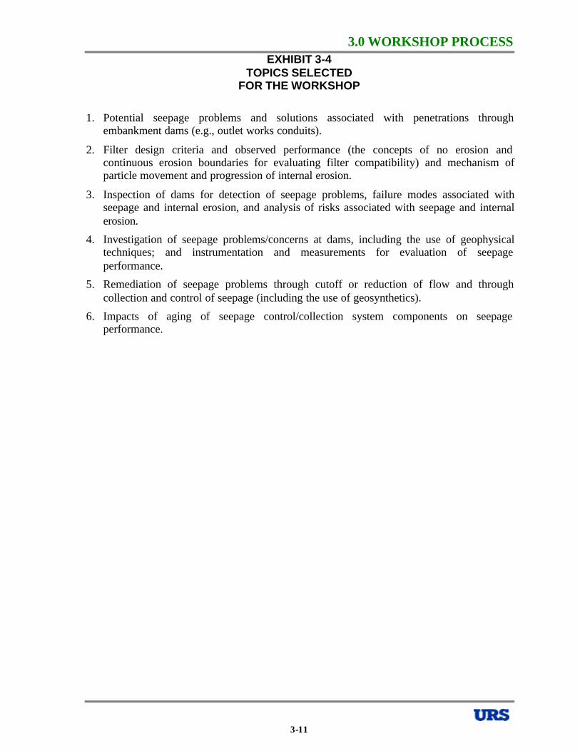
3.0 WORKSHOP PROCESSEXHIBIT 3-4
TOPICS SELECTED FOR THE WORKSHOP
1. Potential seepage problems and solutions associated with penetrations through embankment dams (e.g., outlet works conduits).
2. Filter design criteria and observed performance (the concepts of no erosion and continuous erosion boundaries for evaluating filter compatibility) and mechanism of particle movement and progression of internal erosion.
3. Inspection of dams for detection of seepage problems, failure modes associated with seepage and internal erosion, and analysis of risks associated with seepage and internal erosion.
4. Investigation of seepage problems/concerns at dams, including the use of geophysical techniques; and instrumentation and measurements for evaluation of seepage performance.
5. Remediation of seepage problems through cutoff or reduction of flow and through collection and control of seepage (including the use of geosynthetics).
6. Impacts of aging of seepage control/collection system components on seepage performance.
3-11
3.0 WORKSHOP PROCESS
EXHIBIT 3-5 WHITE PAPER AUTHORS AND TITLES
Author(s) White Paper Title Joseph R. Kula Potential Seepage Problems And Solutions Associated With Penetrations
Through Embankment Dams Robin Fell and Mark Foster The Internal Erosion And Piping Process William O. Engemoen Assessing The Risk Of A Seepage-Related Dam Failure By Means Of
Failure Mode Identification, Risk Analysis, And Monitoring Practices Charles D. Wagner Investigation Of Seepage Problems/Concerns At Dams, Including Use Of
Geophysical Techniques; And Instrumentation And Measurements For Evaluation Of Seepage Performance
James R. Talbot, Steve J. Poulos, Remediation Of Seepage Problems Through Cutoff Or Reduction Of and Ronald C. Hirschfeld Flow And Through Collection And Control Of Seepage Including The
Use Of Geosynthetics Danny K. McCook The Impacts Of Aging Of Seepage Control/Collection System
Components On Seepage Performance
3-12
4.0 WORKSHOP RESULTS FOR INDIVIDUAL TOPICS
4.0 WORKSHOP RESULTS FOR INDIVIDUAL TOPICS
In this section of the report, the results of the workshop are presented and discussed separately for each of the six topics listed in Exhibit 3-4. For each topic, the following items are discussed:
1. The state-of-the-practice white paper.
2. Refinements to the state-of-the-practice white paper.
3. Identification and prioritization of research and development ideas.
4. Preliminary research and development implementation plans.
Consideration of each topic resulted in the selection of four or five research and development ideas for which preliminary implementation plans were developed. Section 5 of the report discusses overall prioritization of the 29 potential research and development plans that were developed separately for the six topics considered.
4.1 TOPIC 1 – POTENTIAL SEEPAGE PROBLEMS AND SULOUTIONS ASSOCIATED WITH PENETRATIONS THROUGH EMBANKMENT DAMS (E.G., OUTLET WORKS CONDUITS)
4.1.1 STATE-OF-THE-PRACTICE WHITE PAPER The strawman state-of-the-practice white paper for this topic was prepared by Joseph R. Kula, and the full paper is presented in Attachment 4 of this report. A brief summary of the highlights of the paper is presented here.
Embankment dams are often penetrated by appurtenant structures, such as outlet works and spillways. The most common penetration is a conduit serving as either an outlet works or spillway conveyance structure. The penetrations can be of various shapes and sizes, and they are constructed of a variety of different materials, with the most common ones being concrete (both cast-in-place and precast), steel, corrugated metal, and, more recently, plastic. The boundaries between the structural materials in the penetrations and the adjacent earth materials provide potential preferential paths for seepage. The susceptibility of these boundaries to seepage is sometimes exacerbated by the difficulty in compacting fill beside and beneath the penetrations, differential settlement of the penetrations, and low stresses adjacent to the penetration caused by arching. Ideally, flow through a conduit penetration is controlled at or near the upstream end, so that the conduit operates with gravity flow. However, there are installations where the control is located at the downstream end and the conduit is constantly pressurized to full reservoir head.
Data collected by the University of New South Wales indicate that about 15 percent of the failures (breaches) reported for embankment dams greater than 15m in height were associated with conduits passing through the dam, and this represents about one-third of the reported failures caused by seepage and piping. The problem appears to have become more prevalent in recent years, possibly at least in part because of the aging of older dams. The National Performance of Dams Program (NPDP) has collected records of 164 incidents related to penetrations through embankment dams. Of these, 87 percent have been occurred in the last 20 years and 75 percent in the last 10 years. A survey of state dam safety programs was conducted for the 1999 ICODS Dam Safety Technical Seminar No. 6 on conduits. In that survey, 14 states reported 1,115 dams with conduits in need of repair; 53 percent being corrugated metal pipes (CMPs), 23 percent being steel pipes, and 20 percent being concrete
4-1
4.0 WORKSHOP RESULTS FOR INDIVIDUAL TOPICSpipes. CMPs appear to be a significant part of the problem. NPDP data indicate that many CMPs rust out in less than 25 years, and that one CMP pipe was reported to have rusted out in only 17 years.
Typical problems associated with penetrations through embankment dams include: 1) seepage and piping along the conduit or other penetration; 2) erosion into the conduit through poor joints, cracks or holes; 3) flow out of the conduit through poor joints, cracks or holes; and 4) structural failure from excessive deformations. Seepage and piping along the penetration can lead directly to formation of an eroded “pipe” from the downstream to the upstream side of the dam, ultimately resulting in formation of a breach. Erosion into a conduit can lead to formation of a pipe from the conduit to the reservoir, which again can ultimately lead to breach of the dam. The erosion into the pipe will occur at a location where the piezometric head in the embankment is higher than the elevation of the defect (joint, crack, or hole) in the conduit. Cracks or holes in the conduit wall can be the result of structural deterioration, and holes can also result from corrosion (e.g., in CMPs). Flow out of the conduit can cause development of a pipe along the outside of the penetration, as in the first type of problem described above. This problem is normally associated with pressurized conduits. Structural failure can lead to cracks and holes through the walls of a conduit, providing the pathways for erosion into or flow out of the conduit. Structural failures can occur with any type of conduit, but they are most often associated with flexible pipes (e.g., CMPs and plastic pipes), that derive most of their load carrying capability from the surrounding backfill. For these types of pipes, if the backfill is not adequately compacted, the pipe can deform excessively under load.
The seepage problems associated with penetrations through embankment dams appear to generally be associated with old design standards, poor construction practices, and material deterioration. Old design standards (pre-1980) included the use of anti-seepage collars as the primary defense against seepage along the penetration. Unfortunately, experience has shown that in many cases the anti-seepage collars were not effective, because poor compaction around the collars offset (in some cases more than offset) the benefit that they provided. Other old design standards that have led to problems include: 1) poor joint details; 2) not accounting for settlements resulting from compressible foundations; 3) the lack of support cradles for round pipes and the resulting reliance on good compaction in the lower “haunches” of the backfill; 4) vertical structural walls, which do not facilitate compaction or accommodate settlement; 5) deep and narrow trenches that lead to low stresses because of arching; and 6) lack of downstream filters around conduits. Construction practices that have contributed to problems include poor joint construction and poor compaction procedures. Problems associated with material deterioration require no further discussion. More recently practices have improved. Beginning in about 1980, seepage diaphragms to collect and control seepage along penetrations have been recommended in place of anti-seepage collars. In addition, concrete cradles or full concrete encasements have become more widely used for round pipes, structural walls have been battered (e.g., 1H:8V or 1H:10V), and steep, narrow trenches have been avoided. There also has been an increased awareness of the importance of quality control for construction related to penetrations through embankment dams.
Inspections are vital to detecting potential problems with conduits and other penetrations, so that adverse conditions can be discovered and remedied before they threaten the safety of the dam. Direct visual inspections are possible for most conduits larger than about 36 inches in diameter, but these inspections require compliance with OSHA regulations for confined space entry. Remote camera inspection technology has been evolving rapidly in recent years, and in many cases it is the preferred method of inspection. For small conduits remote camera
4-2
4.0 WORKSHOP RESULTS FOR INDIVIDUAL TOPICSinspection is the only practical method of visual inspection. In some cases, it is appropriate to supplement visual inspections with geophysical methods such as global seismic investigations, localized seismic investigations, laser scanning and profiling, acoustic and ultrasonic testing, sonar, and ground penetrating radar.
Instrumentation and monitoring can also provide valuable information for assessing potential problems with penetrations. Structural integrity can be monitored and assessed with strain gauges, joint meters, inclinometers, extensometers, settlement plates, and geophysical techniques. Seepage can be monitored and assessed with tracers, geophysical methods, temperature measurements and thermal imaging, gamma and neutron logging, and acoustic devices, in addition to more conventional piezometer installations.
Where problems have been identified with penetrations, rehabilitation techniques have included one or more of the following: replacement, sliplining an existing conduit, cured-in-place pipe liners, filter diaphragms installed around the conduit, grouting, and localized patching of structures. To-date trenchless technologies, other than cured-in-place pipe liners, have seen limited use in dams. However, as these techniques mature in their applications in the sewer industry, it is possible that they may prove applicable to penetrations through dams. Trenchless technologies include molded polyethylene pipes, spiral widening systems, deformed liners made from high strength polyethylene, pipe bursting, and microtunneling.
4.1.2 STATE-OF-THE-PRACTICE REFINEMENT The discussion of the white paper resulted in the identification of the following items to further refine the understanding of the state-of-the-practice:
• There was a general, but not unanimous, consensus that sand (or sand and gravel) filter diaphragms around conduits are preferred over concrete cutoff collars for controlling seepage and piping along the sides of outlet conduits.
• The NRCS/SCS filter diaphragm criteria were developed for 18 to 48 inch diameter pipes. There are no widely available criteria for larger pipes. Diaphragm dimensions for larger pipes are based on engineering judgment based on analysis and evaluation of site-specific conditions.
• Chimney drains in embankments may serve the same purpose as filter diaphragms, if they are located correctly.
• The correct location for a filter diaphragm is dependent on the reservoir head and the phreatic surface through the embankment.
• A filter diaphragm must have an outlet to drain any seepage that enters the diaphragm. The outlet can be provided by a pipe, connection to a chimney or blanket drain, or any one of a number of other suitable means.
• A filter diaphragm will be effective only if the gradation as-installed provides adequate filter protection to up-gradient soils.
• Grouting around pipelines is not recommended as a sole solution for prevention of piping. Grouting will not likely provide 100 percent encapsulation of the conduit and seepage gradients in the “windows” in the grout may actually be higher than the initial gradients before grouting. Grouting can be used to fill or partially fill voids created by piping, to reduce future settlements, but filter diaphragms or other positive means must be used to prevent piping.
4-3
4.0 WORKSHOP RESULTS FOR INDIVIDUAL TOPICS• Bare (unencased) corrugated metal outlet conduits should not be used for new
construction or replacements in significant or high hazard dams. Although many existing dams include bare corrugated metal outlet conduits, their generally poor long-term performance argues strongly against their continued use. In addition, studies have shown that corrugated metal pipe outlet conduits are inferior to concrete pipe outlet conduits, when evaluated on a life-cycle-cost basis.
• There was a general, but not unanimous, consensus that the springline is the recommended minimum height for the top of a conduit cradle, if a cradle is used.
• Flexible pipes and rigid cradles are not compatible. Flexible pipes (corrugated metal, HDPE, etc.) are designed to deflect to a limited degree under load. A rigid cradle prevents deflection of the pipe in the cradle, which can lead to overstressing of the walls of the pipe.
• There was consensus that permanently pressurized pipes through embankments should be either encased (e.g., in concrete) or placed within an outer conduit.
• The workshop participants were not aware of a case in which trenchless technology had been used to construct a conduit through an embankment dam.
• It was noted that the discussion on penetrations in this workshop session did not address vertical penetrations (e.g., piezometers).
4.1.3 PRIORITIZATION OF RESEARCH AND DEVELOPMENT IDEAS The group brainstorming process resulted in the generation of 15 potential research and development ideas, which were then prioritized by the group. The 15 ideas and the results of the prioritization are presented in Exhibit 4-1.
4.1.4 PRELIMINARY RESEARCH AND DEVELOPMENT PLANS The top five ideas listed in Exhibit 4-1 were selected for development of preliminary implementation plans, and those plans are presented in Exhibits 4-2 through 4-6. In some cases, the individual work groups reworded the research and development idea, so the ideas listed in Exhibit 4-1 may not exactly match the ideas listed in Exhibits 4-2 through 4-6.
4.2 TOPIC 2 – FILTER DESIGN CRITERIA AND OBSERVED PERFORMANCE (THE CONCEPTS OF NO EROSION AND CONTINUOUS EROSION BOUNDARIES FOR EVALUATING FILTER COMPATIBILITY) AND MECHANISM OF PARTICLE MOVEMENT AND PROGRESSION OF INTERNAL EROSION
4.2.1 STATE-OF-THE-PRACTICE WHITE PAPER The strawman state-of-the-practice white paper for this topic was prepared by Robin Fell and Mark Foster, and the full paper is presented in Attachment 5 of this report. A brief summary of the highlights of the paper is presented here.
To provide a complete coverage of the issues, the white paper includes a description of the internal erosion process, from initiation through to formation of a breach, and discussions of seepage and internal erosion in the dam and in the foundation.
Historically, nearly 1 in 50 (or approximately 2 percent) of embankment dams larger than 15m in height have experienced a piping incident through the embankment, foundation, or from the embankment to the foundation. Incidents include both failures (a breach resulting
4-4
4.0 WORKSHOP RESULTS FOR INDIVIDUAL TOPICSin uncontrolled release of the reservoir) and seepage “accidents” that did not result in failure. Approximately one-third of the reported incidents led to failure. Of all of the reported incidents, about 50 percent were in the embankment, 40 percent were in the foundation, and 10 percent were from the embankment to the foundation. A smaller percentage of incidents of piping in the foundation, and particularly those from embankment to foundation, progress to failure, than is the case for piping in the embankment. Nearly 50 percent of the reported failures occurred on first filling, and 64 percent occurred within the first five years of operation. In contrast, about 60 percent of the accidents occurred after the first five years of operations. For all failures where the reservoir levels at the times of failure are known, the failures occurred with the reservoir at or above its previous maximum level (85 percent of the cases) or within 1m of its previous maximum level (15 percent of the cases). Seepage gradient alone has been found not to be a good indicator of the likelihood of a piping failure, with failures and accidents reported with gradients as low as 0.05.
The process of a piping failure can be divided into four phases: 1) initiation, 2) continuation of erosion, 3) progression to form a pipe, and 4) formation of a breach. Piping can initiate from backward erosion (movement of soil particles at a free seepage exit point), a concentrated leak (e.g., through a cracked core or along a structural penetration), suffusion (internal instability of the soil – the finer components of the soil being washed out of the coarser matrix), or “blowout” (heave). Continuation of erosion and formation of a pipe are affected by the ability of the pipe to “support a roof.” Case studies suggest that soils with more than 15 percent fines are capable of supporting a roof, even if the fines are not plastic. In addition, the moisture condition of the soil affects its ability to support a roof, with dry or partially saturated soils generally being more likely to support a roof. Stratigraphy can also affect the ability to support a roof; for example an overlying cohesive soil layer can provide a roof for formation of a pipe in clean cohesionless soil. Potential piping breach mechanisms include gross enlargement of the pipe hole, overtopping (resulting from crest settlement or sinkhole formation), unraveling of the downstream slope, and downstream slope instability.
It is suggested that the reason that there are twice as many seepage accidents as there are failures by piping is primarily because in accidents the piping process ceased before a breach mechanism could develop. The cessation of the process resulted either from 1) some characteristic of the zoning of the dam and its foundation, 2) some characteristic of the soil and rock materials in the dam and its foundation, 3) the specific seepage conditions at the dam, and/or 4) intervention by the dam’s operators.
The state-of-the-practice for controlling seepage and internal erosion in new dams and dam rehabiltations is to include designed filters and high permeability zones within the embankment. Erosion from the embankment into rock foundations can be controlled by proper foundation preparation (e.g., concrete or shotcrete over open joints in the rock beneath the core). Erosion within the foundations can be more difficult to control, but can be addressed by providing filters where the seepage will exist or by constructing cutoffs (e.g., diaphragm walls in alluvium).
The issues are more complicated for assessing the safety of existing dams that may not have been designed and constructed according to standard practice. In these cases, the actual conditions and performance data are compared to the desired state-of-the-practice, and engineering judgment is used to decide whether the dam is safe enough. State-of-the-practice filter design criteria are sometimes used in this assessment; however, as discussed below this approach may be too conservative. Over the past 10 to 15 years, some organizations have been using risk assessment methods to provide guidance to the decisions regarding the safety
4-5
4.0 WORKSHOP RESULTS FOR INDIVIDUAL TOPICSof existing dams with respect to seepage. This use of risk assessment methods is considered an evolving state-of-the-practice.
A filter in an embankment dam or its foundation is required to perform two basic functions: 1) prevent erosion of soil particles from the soil it is protecting and 2) allow drainage of seepage water. To achieve this, filters must 1) have an appropriate particle size distributions to control and seal the erosion which may have initiated in the base soil, 2) have sufficient internal stability, 3) be resistant to segregation and particle breakdown during handling, placing, spreading, and compaction, 4) have sufficient permeability and thickness to handle the seepage quantity, and 5) be incapable of holding an open crack. Various organizations and researchers have recommended filter design criteria that will fulfill these requirements. The white paper summarizes recent research by Foster and Fell, at the University of New South Wales, that generally supports the criteria currently used by the NRCS and the USBR, with a few modifications recommended in the white paper. In their research, Foster and Fell found that filters designed according to these criteria can be considered “no erosion” filters – that is the filter seals the base material with practically no erosion of the base material. “Seals” in this sense means prevents movement of soil particles from the base material.
The research by Foster and Fell also indicated that filter materials could be coarser than those resulting from the “no erosion” criteria, but still prevent “continuous erosion” of the base material. As discussed in the white paper, Foster and Fell defined four conditions that they applied to their research results: 1) “no erosion,” as defined above, 2) “some erosion,” where the filter seals after “some” erosion of the base material, 3) “excessive erosion,” where the filter seals, but only after “excessive” erosion of the base soil, and 4) “continuing erosion,” where the filter does not seal, but rather allows “continuous” erosion of the base soil. Based on their research results, they provide recommendations for “excessive erosion” criteria, which they suggest may be applicable in the evaluation of existing dams, particularly in the application of risk assessment methods. Foster and Fell recommend that these criteria be used only with caution, sufficient site-specific data, and qualified engineering judgment, and they specifically recommend that these criteria not be used for design of new dams or dam rehabiltations.
4.2.2 STATE-OF-THE-PRACTICE REFINEMENT The discussion of the white paper resulted in the identification of the following items to further refine the understanding of the state-of-the-practice:
• Some participants noted experience indicating that widely graded materials can be susceptible to suffusion (internal instability).
• Experience seems to suggest that in some conditions there is a potential for “self-healing” to occur before full pipe formation occurs, however, the exact conditions under which this occurs are not clearly understood.
• At present there remains a lack of understanding of the mechanics of piping on the particle level. Such an understanding would help to tie laboratory and field observations together into a common understanding of the piping phenomenon.
• There is a lack of understanding of filter design criteria for coarser materials (gravels and coarser).
• Filters constructed of soil materials should not be over-compacted. In current practice soil filter materials are often compacted to a greater degree than necessary. Over-compaction
4-6
4.0 WORKSHOP RESULTS FOR INDIVIDUAL TOPICSof filter materials can result in reduced permeability and increased potential for the filter materials to be capable of holding an open crack. Soil filter materials should be compacted only to the degree necessary for strength and settlement requirements; this would include compacting the filters sufficiently that they would not liquefy if subjected to earthquake loading. It was the consensus of the participants that 90 percent of modified Proctor compaction (or 65 to 70 percent relative density) would be sufficient in almost all cases. It was also noted by some participants that a “method” specification with some initial field verification testing may be the best approach to preventing over-compaction of filters.
• After extensive discussion, a general consensus was reached that piping can often be an episodic phenomenon. That is, piping with muddy or turbid seepage may occur for some period of time, after which the pipe collapses or stabilizes for some period of time, only to be followed later by another episode of active piping. It may take many repeated episodes of piping before the phenomenon progresses to failure of the dam. The importance of this understanding of the piping phenomenon is that the observation of clear seepage does not necessarily mean that there is no piping problem. It could simply be the case that the observation was made during a period of no active piping. Piping should be considered a possibility for any case of uncontrolled seepage. Inspectors should also look for evidence of past piping episodes (e.g., silt or sand deposits at or downstream of seepage exit points).
• It was a group consensus that the effectiveness of “crack fillers” or “crack stoppers” is unknown – they may or may not be effective.
• Currently there is not a consensus on thickness requirements for horizontal, vertical, or inclined filter zones. Often, constructability is a key factor in determining the minimum thickness. In many cases the thickness required to carry expected flows is less than that required in construction to assure continuity of the filter zone.
• For design of new structures, it is the state-of-the-practice to assume that fine-grained embankment materials crack.
4.2.3 PRIORITIZATION OF RESEARCH AND DEVELOPMENT IDEAS The group brainstorming process resulted in the generation of 10 potential research and development ideas, which were then prioritized by the group. The 10 ideas and the results of the prioritization are presented in Exhibit 4-7.
4.2.4 PRELIMINARY RESEARCH AND DEVELOPMENT PLANS The top five ideas listed in Exhibit 4-7 were selected for development of preliminary implementation plans, and those plans are presented in Exhibits 4-8 through 4-12. In some cases, the individual work groups reworded the research and development idea, so the ideas listed in Exhibit 4-7 may not exactly match the ideas listed in Exhibits 4-8 through 4-12.
4-7
4.0 WORKSHOP RESULTS FOR INDIVIDUAL TOPICS
4.3 TOPIC 3 – INSPECTION OF DAMS FOR DETECTION OF SEEPAGE PROBLEMS, FAILURE MODES ASSOCIATED WITH SEEPAGE AND INTERNAL EROSION, AND ANALYSIS OF RISKS ASSOCIATED WITH SEEPAGE AND INTERNAL EROSION
4.3.1 STATE-OF-THE-PRACTICE WHITE PAPER The strawman state-of-the-practice white paper for this topic was prepared by William O. Engemoen, and the full paper is presented in Attachment 6 of this report. A brief summary of the highlights of the paper is presented here.
This paper presents the state-of-practice (with a bias to U.S. Bureau of Reclamation practices) for the surveillance and monitoring of dams and the use of this information in the evaluation of potential risks of a seepage-related failure.
Reclamation’s current surveillance and monitoring program for high and significant hazard dams includes several different components. Typically, Reclamation dams are observed and inspected frequently by dam tenders and operations personnel, particularly when the reservoirs are at or above normal high operating levels. Annually, representatives from Reclamation’s Area Offices complete a detailed examination of each dam and fill out an inspection report. Every three years, each dam is subjected to a Periodic Facility Review by a team from the Regional Office. Finally, every six years, each dam is subjected to a Comprehensive Facility Review (CFR) by a team of specialists from Reclamation’s Technical Service Center. The overall process includes visual inspections, collection and evaluation of monitoring data, evaluation of failure modes, and assessments of the risks of failure. All personnel involved in the process are trained in dam inspection, operation, and performance. If potential problems or unacceptable risks are identified for a particular dam it is targeted for further evaluation or other appropriate action.
Surveillance and monitoring programs are different for dams operated by other organizations or subject to other jurisdictions. However, the Reclamation program points out several important aspects of a good program. First, surveillance and monitoring should be completed in a regular, thorough, and prescribed manner. The program needs to be completed by appropriately trained and experienced personnel, and available monitoring data should be evaluated and considered. Finally, appropriate actions need to be taken in response to the findings resulting from the surveillance and monitoring activities.
Reclamation’s monitoring and surveillance program is guided in many ways by identification of potential failure modes and the assessment of risks associated with those failure modes. Consequently, the white paper includes a discussion of how Reclamation employs failure mode analysis and risk assessment for seepage-related issues, followed by further discussion of monitoring and surveillance, all of which is briefly summarized below.
Failure mode evaluation is used by Reclamation to help identify key aspects of a dam’s performance that should be monitored to best detect potential seepage problems. Seepage through and under an embankment dam can, given the right situation, lead to failure by any one or more of following the potential failure modes:
Piping – Erosion initiates at a downstream exit point and continues in an upstream direction. For this to happen there must be a flow path with water, an unprotected exit for soil particles to escape through, erodible material within the flow path, material(s) capable of supporting a “pipe” or “roof,” and sufficient seepage gradients.
4-8
4.0 WORKSHOP RESULTS FOR INDIVIDUAL TOPICSSeepage Erosion or Scour – Loss of material occurs at an erosional surface where concentrated flow is located (e.g., a crack in the core or at the dam/foundation contact).
Internal Erosion by Suffusion (Internal Instability) – The finer-grained particles of a soil are washed through the matrix created by the coarser-gained particles.
High, Confined Pore Pressures in Foundation – High seepage pressures cause blowout-type failures, which, in certain circumstances, can be lead to traditional piping – sometimes called “piping by heave.”
The various different seepage and piping failure modes that can develop can be generally categorized into three main types – 1) internal erosion through the embankment, 2) internal erosion through the foundation, and 3) internal erosion of embankment into/at the foundation.
After failure modes have been identified, Reclamation uses risk assessment methods to evaluate the risks associated with those failure modes. The general formulation of risk used by Reclamation is that Risk = [Probability of Loading] x [Probability of Adverse Response (Failure), Given the Loading] x [Adverse Consequences, Given the Failure]. Reclamation uses three basic types of risk analyses in its dam safety evaluations: 1) a risk-based profiling system, 2) CFR risk analysis, and 3) issue evaluation risk analysis. The first two types are relatively simple and are used to complete portfolio and screening-level evaluations to determine if further studies are needed. The third type is significantly more complex and is used when the need for modifications (either structural or non-structural) to a dam is being considered. The issue evaluation risk analysis is completed by a team of individuals led by two trained facilitators. Typically, the team constructs event trees for the various events required to produce a failure according to each of the failure modes. Expert elicitation is then used to estimate probabilities for the various branches of the event trees, so that probabilities of failure can be calculated. Event trees for seepage-related failure modes typically include the following stages: 1) initiation, 2) continuation of internal erosion, 3) progression of the internal erosion process, 4) early intervention, 5) breach initiation, and 6) heroic intervention. Each stage may be characterized by one or more branches in the event tree. Issue evaluation risk analyses are completed for both existing conditions and possible corrective actions to assess the risk reduction provided by the corrective actions, and the results are used as part of Reclamation’s decision process for implementing corrective actions.
At Reclamation, the knowledge and understanding developed from failure mode identification and risk analysis are used in the monitoring and surveillance program. In many ways, they provide guidance on “what to look for and where.” In developing its monitoring and surveillance programs, Reclamation incorporates: 1) integration of analysis with inspection, 2) emphasis on routine and frequent visual observations, 3) advance identification of what to look for and where, 4) inclusion and evaluation of instrumentation data, 5) consideration of periodic videotape inspections of outlet works and drainage systems, 6) consideration of automated early warning systems, and 7) coordination of monitoring and emergency action plans. In its monitoring programs Reclamation also attempts to 1) fight complacency, 2) pay close attention to any observed changes, and 3) recognize the limitations of instrumentation data (e.g., piezometer data may not provide warning of a seepage problem unless it is in exactly the right place).
4.3.2 STATE-OF-THE-PRACTICE REFINEMENT The discussion of the white paper resulted in the identification of the following items to further refine the understanding of the state-of-the-practice:
4-9
4.0 WORKSHOP RESULTS FOR INDIVIDUAL TOPICS• There are currently two different approaches to quantitative risk analysis for seepage
through embankment dams. They can be broadly categorized as 1) the statistical-based method and 2) the degree-of-belief-based method. The general consensus is that the degree-of-belief-based method is presently considered to be the state-of-the-practice for risk analysis for dams, and this will probably remain so for the foreseeable future. At the workshop, the BC Hydro representative requested that it be specifically noted that his organization does not presently support the use of detailed quantitative risk analysis (with either approach) for dam seepage issues. The reader is referred to the report of the March 2000, Logan, Utah Workshop on Risk Analysis for Dams (another FEMA/ASDSO sponsored workshop) for a more extensive treatment of this topic. That report is also a part of FEMA’s National Dam Safety Act Report Series
• Some organizations (the Bureau of Reclamation and some states) are using simplified prioritization systems based on risk approaches. However, some believe that these approaches are subject to some misinterpretation because the results do not specifically address likelihood of occurrences.
• The use of risk analysis in the United States is influenced by the regulatory environment. At present the applicability of risk analysis is limited, because most regulatory agencies (at both the state and federal levels) do not accept risk analysis as a basis for actions to be taken. This situation is likely to change in the future.
• Risk analysis is based on available knowledge about the dam being considered, as are all other engineering judgments concerning dams.
• The qualifications, training, and experience of dam inspectors and operators are highly variable in the United States. Yet the qualifications, training, and experience of these individuals are critical to professional judgments that must be made in operating and maintaining a dam.
• Automated monitoring installations for early warning systems need to be designed so that they measure parameters that can clearly provide adequate warning. For example, tailwater level monitors are sometimes used for early warning, but in many cases they will not provide adequate advance warning to the population-at-risk (e.g., the alarm would come too late). By contrast, piezometers in the pervious downstream shell of a dam may, in the right situation, provide a sensitive measure of changing conditions.
4.3.3 PRIORITIZATION OF RESEARCH AND DEVELOPMENT IDEAS The group brainstorming process resulted in the generation of 10 potential research and development ideas, which were then prioritized by the group. The 10 ideas and the results of the prioritization are presented in Exhibit 4-13. Note that two of the ideas were judged to have been addressed by the March 2000 Risk Analysis Workshop in Logan, Utah, and, therefore, were not included in the prioritization. In addition, a third idea, which received a significant number of votes but did not rank in the top five, was combined with one of the top five ideas in the development of implementation plans.
4.3.4 PRELIMINARY RESEARCH AND DEVELOPMENT PLANS The top five ideas listed in Exhibit 4-13 were selected for development of preliminary implementation plans, and those plans are presented in Exhibits 4-14 through 4-18. In some cases, the individual work groups reworded the research and development idea, so the ideas listed in Exhibit 4-13 may not exactly match the ideas listed in Exhibits 4-14 through 4-18.
4-10
4.0 WORKSHOP RESULTS FOR INDIVIDUAL TOPICS4.4 TOPIC 4 – INVESTIGATION OF SEEPAGE PROBLEMS/CONCERNS AT
DAMS, INCLUDING THE USE OF GEOPHYSICAL TECHNIQUES; AND INSTRUMENTATION AND MEASUREMENTS FOR EVALUATION OF SEEPAGE PERFORMANCE
4.4.1 STATE-OF-THE-PRACTICE WHITE PAPER The strawman state-of-the-practice white paper for this topic was prepared by Charles D. Wagner, and the full paper is presented in Attachment 7 of this report. A brief summary of the highlights of the paper is presented here.
A program to investigate seepage problems and concerns at a dam is typically designed to develop a sufficient understanding of the stratigraphic and phreatic features of the dam and its foundation. The field investigation program should achieve the following five main objectives:
1. augment existing data,
2. assess the subsurface soil and rock conditions of the embankment, abutments, and foundation,
3. identify any artesian layers,
4. obtain piezometric data,
5. install additional piezometers strategically to fill any data gaps.
Methods commonly used in investigating seepage concerns and problems include a) geotechnical drilling, sampling, and testing programs, 2) installation and monitoring of piezometers and groundwater observation wells, and installation of flumes, weirs, and collection pipes to monitor seepage quantities and characteristics (e.g., turbidity, water chemistry, and water temperature). Geophysical methods are sometimes included in seepage investigation programs, although less frequently than the other methods listed above.
Any investigation program should begin with a thorough review of pertinent available information. Although the extent of available information may vary from extensive for well-documented dams to nearly nonexistent for many older dams, whatever information is available should be thoroughly studied and understood. A thorough understanding of the available information will help guide the investigation program and increase its effectiveness and efficiency.
The most commonly used geotechnical investigation method is the Standard Penetration Test (SPT) boring. SPT borings provide a) data on subsurface stratigraphy, b) disturbed samples for laboratory index testing, and c) blowcounts that provide a measure of in-place consistency and density of soils. The SPT borings can be completed with the installation of piezometers to provide information on phreatic conditions. If required, undisturbed tube samples can be taken in SPT borings, to provide high quality samples for laboratory engineering property tests. SPT borings can also be extended into bedrock, using coring or augering, if the characteristics of the rock are important to the seepage concerns. One drawback of the typical SPT boring is that soil samples are normally taken at five-foot vertical intervals in the boring, so they do not provide a continuous profile of the soil strata that are penetrated. This can be remedied by taking continuous SPT samples, but at a potentially significant increase in investigation cost, particularly for deep borings. In addition, care must be exercised if the boring penetrates strata under artesian pressures, because the boring provides a direct hydraulic connection between the artesian pressure and
4-11
4.0 WORKSHOP RESULTS FOR INDIVIDUAL TOPICSthe ground surface. In the extreme case, such a boring could provide a pathway for the initiation of piping.
Another common geotechnical investigation method sometimes used in seepage investigations is the open test pit or test trench, used to directly expose and examine subsurface conditions at shallow depth.
Piezocone Penetration Tests (CPTu) can be a valuable part of a seepage investigation program. The CPTu test is a quick, efficient way to obtain nearly continuous profiles of inferred soil property data and piezometric information, with minimal site disturbance. The soil property data are inferred from the tip and sleeve resistances and the pore pressure readings obtained as the cone is pushed into the ground. Piezometric data are obtained by completing piezocone dissipation tests to measure stabilized piezometric levels. There are, however, several limitations to the CPTu test. First, the CPTu test does not provide any physical soil samples; all of the soil property information must be inferred from the piezocone readings. This can be remedied on a site-specific basis by using both SPT and CPTu investigations and correlating the results of the two methods. Second, the CPTu test equipment cannot penetrate boulders or very hard or dense soils. Third, the practical depth of penetration of the CPTu test is less than that of SPT borings.
Piezometers can be installed in boreholes, and there are some types of piezometers that can be installed by pushing them into the subsurface strata without the need for a borehole. Piezometers can be either isolated-tip or open-well types. Isolated tip piezometers are those that measure the piezometric level within a limited vertical horizon, while open-well type piezometers measure the average piezometric level over nearly the entire depth of a borehole. The physical compositions of the piezometers can be of several different types (e.g., screened pipe sections, porous tips, vibrating wire piezometers, hydraulic piezometers, etc.), and the appropriate type of piezometer for each application should be based in large part on the required response time for the instrument. Special procedures are required to install piezometers in soil strata with artesian pressures (see discussion above regarding SPT borings).
Permeabilities of subsurface strata can be investigated with several different methods, such as constant and falling head permeability tests in boreholes or piezometers, CPTu dissipation tests, packer pressure tests (in bedrock), and laboratory permeability tests on undisturbed samples.
In some cases, geophysical investigations can be used to help interpret or explore the dams or foundations where intrusive methods would be expensive and/or not feasible due to physical constraints. Methods of geophysical investigations that have been used in seepage investigations include, but are not limited to, ground penetrating radar, spontaneous (self)-potential surveys, electromagnetic induction surveys, very low frequency surveys, resistivity surveys, and seismic refraction surveys.
Monitoring of piezometers and seepage collection points (weirs, flumes, etc.) should be regularly performed so a record of seepage is established. Reservoir and tailwater levels should be recorded whenever readings are taken, so that relationships between hydraulic head and piezometric levels and seepage quantities can be evaluated. It may also be appropriate to collect precipitation and temperature data to allow evaluation of the effects of those factors. Dye testing is another method that can be used to investigate seepage paths. Colored dyes can be injected into boreholes or released at specific locations in the reservoir, and downstream seepage locations can be observed for appearance of the dye. In a similar,
4-12
4.0 WORKSHOP RESULTS FOR INDIVIDUAL TOPICSwater chemistry tests and water temperature measurements can be used to assess potential sources of seepage water.
4.4.2 STATE-OF-THE-PRACTICE REFINEMENT The discussion of the white paper resulted in the identification of the following items to further refine the understanding of the state-of-the-practice:
• Although actual investigation practices vary widely, it was the consensus of the workshop participants that the recommended state-of-the-practice should be that drilling should not be done in the core of an existing embankment dam unless absolutely necessary, and then only with carefully planned precautions and dry drilling (e.g., auger) methods. The risk of hydraulic fracturing is too great to support drilling in the core without appropriate justification.
• It was the consensus of the workshop participants that drilling or test pitting should not be done at the downstream toe of a dam with water stored in the reservoir, without contingency plans and stockpiling of weighted filter materials (e.g., sand and gravel) to be used in the event of a seepage incident. It is also essential that such explorations be completed with the on-site presence of experienced personnel with the knowledge to react appropriately to any seepage incidents that may occur.
• Care should be taken to avoid building seepage defects into embankments by the installation of instruments. A cited example was the installation of hydraulic piezometers with the hydraulic tubes running through the embankment core in a transverse direction. These tubes could provide pathways for seepage and piping to initiate.
• It was the consensus of the workshop participants that they generally advised against installing piezometers in an embankment core, unless there were very compelling reasons for the instruments. The workshop participants felt that, in most cases, piezometers in the core do not provide significant additional understanding of the performance of the dam beyond that which can be obtained from piezometers in the upstream and downstream shells, which are much safer locations for the instruments.
• Piezometers are tools whose careful installation and subsequent data interpretation, in conjunction with other investigative techniques, may provide valuable information in diagnosing seepage conditions. However, the limitations of what the piezometers record must be recognized, and the piezometer data must be used in conjunction with other information (e.g., seepage rates, seepage locations, etc.) to correctly diagnose seepage conditions. Since piping channels in embankments are often relatively long, narrow features, it is not likely that piezometers will be located at exactly the correct locations to provide direct data regarding the piping phenomenon.
• The dam engineering profession in general remains skeptical or cautious regarding the effectiveness of geophysical techniques for investigation of seepage problems, possibly because the methods are perceived as not proven sufficiently to establish a high degree of confidence. This situation may be caused by a mismatch in engineers expectations and the reality of what the methods can produce. Regrettably, this may be the result of some geophysical practitioners “over-selling” the capabilities of the various methods. There have been some successful applications of geophysical methods, and some of the methods show promise. Successful applications will likely increase in the future through research efforts such as those of the Canadian Electric Association.
4-13
4.0 WORKSHOP RESULTS FOR INDIVIDUAL TOPICS• The Bureau of Reclamation cited the recent successful use of side-scan sonar in a
reservoir to assist in locating possible sinkholes in the upstream abutment of a dam.
• All instrumentation in a dam should be part of a carefully designed and implemented instrumentation plan that addresses need, purpose, instrumentation types, instrumentation locations, and data collection and evaluation. Instrumentation should not be installed simply for the purpose of having instrumentation. Similarly, instrumentation data should not be collected if it is not processed and evaluated.
4.4.3 PRIORITIZATION OF RESEARCH AND DEVELOPMENT IDEAS The group brainstorming process resulted in the generation of eight potential research and development ideas, which were then prioritized by the group. The eight ideas and the results of the prioritization are presented in Exhibit 4-19.
4.4.4 PRELIMINARY RESEARCH AND DEVELOPMENT PLANS The top five ideas listed in Exhibit 4-19 were selected for development of preliminary implementation plans, and those plans are presented in Exhibits 4-20 through 4-24. In some cases, the individual work groups reworded the research and development idea, so the ideas listed in Exhibit 4-19 may not exactly match the ideas listed in Exhibits 4-20 through 4-24.
4.5 TOPIC 5 – REMEDIATION OF SEEPAGE PROBLEMS THROUGH CUTOFF OR REDUCTION OF FLOW AND THROUGH COLLECTION AND CONTROL OF SEEPAGE, (INCLUDING THE USE OF GEOSYNTHETICS)
4.5.1 STATE-OF-THE-PRACTICE WHITE PAPER The strawman state-of-the-practice white paper for this topic was prepared by James R. Talbot, Steve J. Poulos, and Ronald C. Hirschfeld, and the full paper is presented in Attachment 8 of this report. A brief summary of the highlights of the paper is presented here.
There are two principal problems associated with seepage through, around, and beneath an embankment dam: piping (internal erosion) and excessive water loss.
Remedial measures for preventing piping are aimed at controlling seepage so that the seepage does not cause internal erosion of soil from the embankment, foundation, or abutments of a dam. Remedial measures for preventing piping may not reduce the rate of seepage and, in fact, often increase the rate of seepage.
Remedial measures for reducing water loss are aimed at reducing the quantity of seepage through the embankment, foundation, and abutments. Although such measures may reduce the pressures and the rate of water flow through a dam, its foundation, or abutments, it is nevertheless vital to install proper drainage systems on the downstream side of the dam as the primary line of defense against piping.
The following sequence of activities is often followed to recognize and correct seepage problems within a dam:
• field observation of a seepage problem or potential problem;
• information collection and evaluation to determine the cause of the problem;
• design of remedial measures;
• construction of remedial measures; and
• observations of effectiveness of the repairs.
4-14
4.0 WORKSHOP RESULTS FOR INDIVIDUAL TOPICSThe addition of downstream drainage is usually the best solution for controlling seepage in embankment dams. Control of seepage can be accomplished by:
• adding a drainage zone by removing a portion of the downstream slope and constructing a new filter-drain covered by a reconstructed downstream slope;
• adding a drainage zone by constructing a filter-drain on the existing downstream slope and covering the drain with a new downstream shell zone;
• adding an embankment chimney drain to the dam by trenching into the dam and backfilling the trench with appropriate filter material;
• installing a toe drain extending into the foundation at the toe of the dam;
• installing a downstream, weighted, blanket drain;
• installing downstream relief wells;
• cleaning existing clogged drains; and
• cleaning existing relief wells.
The solution that is best-suited to a particular dam will depend on a variety of factors, as discussed in the white paper. Some of the more important factors to be considered are a) the embankment zoning and foundation stratigraphy, b) the seepage patterns and quantities, c) seepage pressures, d) the ability to lower the reservoir for construction, e) the availability of construction materials, and f) property constraints and construction access.
Reducing the amount of seepage through dams will have the benefit of saving water as a resource; lowering the seepage pressures within the dam, foundation and abutments (thus reducing to some extent the probability of a piping failure); and reducing the required size of downstream seepage control systems. It is the opinion of the white paper authors that proper downstream drainage collection and safe discharge must always accompany any flow-reduction technique. Methods available to reduce the amount of seepage include:
• an upstream blanket constructed with low permeability materials (e.g., soil, asphalt, soil cement, roller compacted concrete, concrete, or a geomembrane);
• a “cutoff” or facing on the upstream slope of the dam constructed with low permeability material (e.g., soil, soil and bentonite mixtures, soil cement, roller compacted concrete, concrete, asphalt, metal, masonry, or a geomembrane); and
• an internal “cutoff” within the dam and foundation constructed of low permeability material (e.g., concrete, soil-bentonite mixtures, soil-cement mixtures, sheet piling, or grout) – sometimes called diaphragm walls and constructed with such methods as slurry trench excavations, deep soil mixing, or jet grouting.
In the previous paragraph, the term “cutoff” is in quotations because almost no technique used for this purpose will actually completely cut off water flow. There always will be leakage that must be safely collected and drained on the downstream side of the cutoff.
Many of the factors affecting the selection of the most appropriate solution for seepage reduction are the same as those for seepage collection, as discussed in the white paper. Two other significant factors that affect the selection for seepage reduction measures are a) the necessity for limiting the potential of hydraulic fracturing when constructing an internal
4-15
4.0 WORKSHOP RESULTS FOR INDIVIDUAL TOPICScutoff, and b) the need to provide protection against erosion and animal damage for shallow elements such as upstream blankets and upstream facings.
Geosynthetic materials (geomembranes and geotextiles) have been used in dam remediation projects to control and reduce seepage. The white paper authors present some precautions regarding use of these materials. When geomembranes are used for blankets or seepage barriers, they are vulnerable to puncture during and after installation. The design and installation of geomembranes must be done in a such a manner as to minimize this risk. In addition, the low friction angle at the geomembrane-soil interface and the possibility of high pore water pressures at the interface must be considered in the design. Pending further research, the white paper authors recommend that the use of geotextiles as filters be avoided in dams. In addition to concerns regarding damage during installation, the white paper authors cite two other concerns: a) the potential for the geotextile to tear because of movements in the dam, and b) the potential for the geotextile to plug because of the physical conditions at the soil-geotextile interface.
4.5.2 STATE-OF-THE-PRACTICE REFINEMENT The discussion of the white paper resulted in the identification of the following items to further refine the understanding of the state-of-the-practice:
• Constructability and construction quality assurance/quality control are critical to successful and safe seepage collection/drain system performance.
• Seepage collection pipes in blanket drains under downstream shells of dams are being used – the potential disadvantages (collapse, plugging, drilling into them) of this application should be recognized when they are used.
• Although in current practice cutoffs are being used as a sole solution for seepage/piping problems, the consensus of the workshop group supports the position in the white paper that cutoffs should always be used together with adequate downstream collection and control systems.
• Seepage collection systems should be designed for significantly greater (3 to 10 times) flow capacity than expected.
• The current practice for the use of geotextiles in seepage collection systems varies widely amongst organizations and practitioners involved in dam engineering. After much discussion, it was the consensus of the group that a) geotextiles should not be used in locations that are both critical to safety and inaccessible for replacement, and b) geotextiles can be used in locations that are critical for safety but accessible for replacement. However, in the second case the engineer must assess the potential hazard posed by failure of the geotextile and the time available to respond and repair or replace the geotextile. This position may change in the future with data on long-term, in-place performance of geotextiles in dam applications.
• Several participants related experience with poor performance with the rate of inflow into slotted or perforated pipes when the sizes of the openings in the pipes and the gradations of the surrounding soil filters were designed according to currently recommended guidelines. It appears that the soil particles can partially to substantially plug the opening, resulting in limited inflow. This appears to be less of a problem with pipes surrounded by gravel than it is for pipes surrounded by sand or sand/gravel mixtures.
4-16
4.0 WORKSHOP RESULTS FOR INDIVIDUAL TOPICS• The workshop participants were not aware of any currently available guidelines regarding
the extent and spacing of slots or perforations in pipe walls that can be allowed without compromising the structural capacity of the pipe.
• It was the consensus of the workshop participants that the recommended state-of-the-practice for application of pressure grouting (cement or chemical) in seepage remediation should be that a) high-pressure grouting should never be used in the embankment core and b) high-pressure grouting is acceptable in rock foundations, with appropriate care; however, it was the experience of the group that grouting was often not a permanent solution.
4.5.3 PRIORITIZATION OF RESEARCH AND DEVELOPMENT IDEAS The group brainstorming process resulted in the generation of 12 potential research and development ideas, which were then prioritized by the group. The 12 ideas and the results of the prioritization are presented in Exhibit 4-25.
4.5.4 PRELIMINARY RESEARCH AND DEVELOPMENT PLANS The top five ideas listed in Exhibit 4-25 were selected for development of preliminary implementation plans, and those plans are presented in Exhibits 4-26 through 4-30. In some cases, the individual work groups reworded the research and development idea, so the ideas listed in Exhibit 4-25 may not exactly match the ideas listed in Exhibits 4-26 through 4-30.
4.6 TOPIC 6 – IMPACTS OF AGING OF SEEPAGE CONTROL/COLLECTION SYSTEM COMPONENTS ON SEEPAGE PERFORMANCE
4.6.1 STATE-OF-THE-PRACTICE WHITE PAPER The strawman state-of-the-practice white paper for this topic was prepared by Danny K. McCook, and the full paper is presented in Attachment 9 of this report. A brief summary of the highlights of the paper is presented here.
This paper discusses the components commonly included in drainage systems for embankment dams, the mechanisms of aging that may impact their performance, and remedial alternatives.
Drainage systems in embankment dams may include some or all of the following elements:
• foundation trench and blanket drains with and without collector pipes;
• embankment chimney drains and filters;
• relief wells;
• concrete structural drains; and
• other miscellaneous features.
The mechanics of aging or deterioration of a drainage system may categorized as follows:
• material deterioration;
• mineralization (encrustation);
• bacterial deposits;
• cementation of filter media;
4-17
4.0 WORKSHOP RESULTS FOR INDIVIDUAL TOPICS• siltation of gravel packs;
• effects of repeated maintenance activities;
• vandalism; and
• impacts of vegetation.
The drainage components that may be subject to problems caused by aging include:
• granular filter/drain materials,
• pipes,
• well screens,
• fittings, and
• geosynthetics.
When drainage systems are damaged or deteriorate the systems collect seepage less efficiently than intended. Typical problems resulting from damaged or deteriorated drainage systems include:
• development of cracks or large openings that can provide pathways for internal erosion (piping) of embankment or foundation soils;
• reduced flow capacity and increased pressures due to decreased cross-sectional area;
• leaks or openings in system piping that can lead to internal erosion of surrounding soils;
• increased pore pressures caused by decreased capacity; and
• reduced seepage capacity and increased pressures because of siltation of filters and slotted pipes or well screens.
Relief wells are especially susceptible to deterioration and aging. The most common problems associated with relief wells have been loss of check valve reliability, corrosion of screens and guards, encrustation/mineralization, deterioration of wood staves, vandalism, and siltation. To correct these relief well problems the most commonly used maintenance procedures include pumping, surging, jetting, acidizing, chlorination (disinfectants), and surfactants. Less commonly used relief well maintenance procedures include lime application, the Vyredox methods, activated carbon filters, ultraviolet light, ultrasonic vibration, and heat treatment (pasteurization).
Cameras of various types can be used to inspect pipes included in seepage collection systems, and recent advances in camera technology have resulted in the ability to inspect smaller pipes and this trend in technological advances probably will continue in the future. Pipe lining procedures and pipe cleaning procedures (e.g., surging, reaming, and jetting) can be used to attempt to rehabilitate pipes in existing seepage collection systems, if the pipes are accessible for these procedures or can be made accessible.
4.6.2 STATE-OF-THE-PRACTICE REFINEMENT The discussion of the white paper resulted in the identification of the following items to further refine the understanding of the state-of-the-practice:
4-18
4.0 WORKSHOP RESULTS FOR INDIVIDUAL TOPICS• Lamping (illuminating with a light) can be a useful method for inspecting the condition
of horizontal drain pipelines.
• Creosote materials used in some early wooden pipe materials are considered hazardous waste.
• Heated, chlorinated water applied to zones in wells, using a packer system, has been found to be successful in rehabilitating the wells.
• Regular and thorough maintenance is essential to the continued effectiveness of relief wells.
• The workshop group reported knowledge of evidence of long-term deterioration of embankment cores due to such occurrences as softening through wetting, mass movement during drawdown, suffusion, desiccation, and differential settlement and arching adjacent to structures.
• There are reported cases of long-term deterioration of grout curtains.
• There are reported cases of long-term deterioration of foundations due to solutioning and washout of in-fill materials (e.g., joint fill or paleokarst collapse features).
• There are problems in drain pipelines with deposits other than iron bacteria and carbonates, but to a much more limited extent.
• There is some anecdotal information in the profession indicating that some filters may have altered over time so that they could hold an open crack after alteration.
• Weep holes in structural walls (e.g., concrete spillway walls) can plug over time, and may require maintenance.
• Tree roots can invade and damage dam drain pipes.
• It was the consensus of the group that corrugated metal pipes should not be used for drain pipes in seepage collection systems, because of their record of deterioration.
4.6.3 PRIORITIZATION OF RESEARCH AND DEVELOPMENT IDEAS The group brainstorming process resulted in the generation of eight potential research and development ideas, which were then prioritized by the group. The eight ideas and the results of the prioritization are presented in Exhibit 4-31. Note that two ideas, which did not rank in the top four were combined with two of the top four ideas in the development of implementation plans.
4.6.4 PRELIMINARY RESEARCH AND DEVELOPMENT PLANS The top four ideas listed in Exhibit 4-31 were selected for development of preliminary implementation plans, and those plans are presented in Exhibits 4-32 through 4-35. In some cases, the individual work groups reworded the research and development idea, so the ideas listed in Exhibit 4-31 may not exactly match the ideas listed in Exhibits 4-32 through 4-35.
4-19
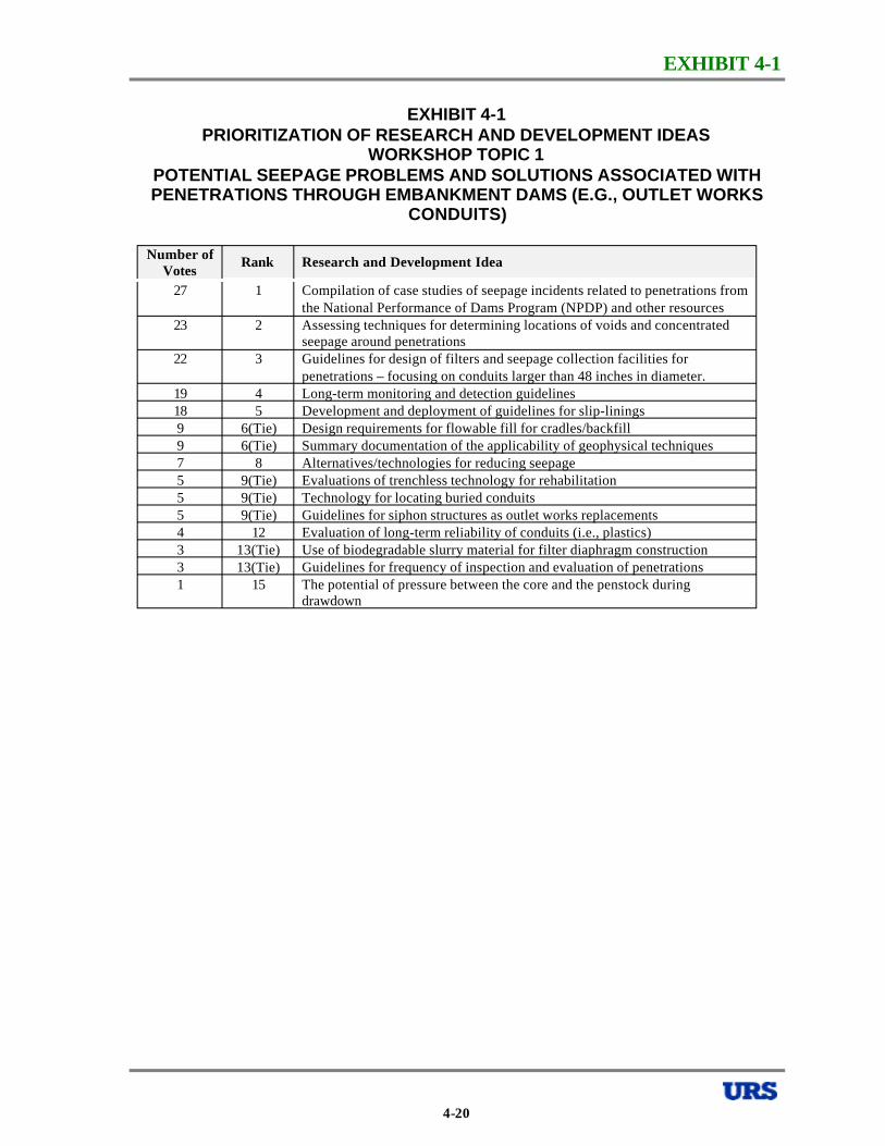
EXHIBIT 4-1
EXHIBIT 4-1 PRIORITIZATION OF RESEARCH AND DEVELOPMENT IDEAS
WORKSHOP TOPIC 1 POTENTIAL SEEPAGE PROBLEMS AND SOLUTIONS ASSOCIATED WITH PENETRATIONS THROUGH EMBANKMENT DAMS (E.G., OUTLET WORKS
CONDUITS)
Number of Votes
Rank Research and Development Idea
27 1 Compilation of case studies of seepage incidents related to penetrations from the National Performance of Dams Program (NPDP) and other resources
23 2 Assessing techniques for determining locations of voids and concentrated seepage around penetrations
22 3 Guidelines for design of filters and seepage collection facilities for penetrations – focusing on conduits larger than 48 inches in diameter.
19 4 Long-term monitoring and detection guidelines 18 5 Development and deployment of guidelines for slip-linings 9 6(Tie) Design requirements for flowable fill for cradles/backfill 9 6(Tie) Summary documentation of the applicability of geophysical techniques 7 8 Alternatives/technologies for reducing seepage 5 9(Tie) Evaluations of trenchless technology for rehabilitation 5 9(Tie) Technology for locating buried conduits 5 9(Tie) Guidelines for siphon structures as outlet works replacements 4 12 Evaluation of long-term reliability of conduits (i.e., plastics) 3 13(Tie) Use of biodegradable slurry material for filter diaphragm construction 3 13(Tie) Guidelines for frequency of inspection and evaluation of penetrations 1 15 The potential of pressure between the core and the penstock during
drawdown
4-20

EXHIBIT 4-2
EXHIBIT 4-2 RESEARCH AND DEVELOPMENT
IMPLEMENTATION PLAN, R&D TOPIC 1A COMPILATION OF CASE HISTORIES OF SEEPAGE INCIDENTS RELATED TO
PENETRATIONS THROUGH EMBANKMENT DAMS 1. Description
A. Why is this a priority research/development item? Penetrations are the ancillary structures most prone to deterioration and seepage leading to failure.
B. What is the expected outcome? Development of a volume of case histories with executive summary of lessons learned on issues related to seepage along, into, and out of penetrations through dams.
2. Project Tasks and Needs
A. What tasks are to be done? B. How is the problem to be solved?
1) Compile case histories with support documents (literature search, photos, plans, specs, etc.)
a. Compile database/library in ASDSO.
b. Evaluate and categorize incidents, and select representative cases.
c. Develop executive summary/statistics/solutions.
d. Prepare published report.
e. Develop web site with all case histories.
f. Develop bibliography.
2) Federally-funded/ASDSO-funded graduate degree research project
3) Potential problem: Access to case history documents may be restricted by litigation/owner liability issues.
3. Project Lead and Contact
A. Who is working in this area? Marty McCann, Robin Fell, ICOLD, USCOLD (USSD), U.S. Bureau of Reclamation (USBR), U.S. Natural Resources Conservation Service (NRCS), CANCOLD, etc.
B. Who might be able to lead the project? Marty McCann, University (Southern, Utah State, many others), Federal agency.
C. Who are good candidates to complete the work? Establish Advisory Committee to direct project, possibly including Robin Fell from the University of New South Wales.
4-21
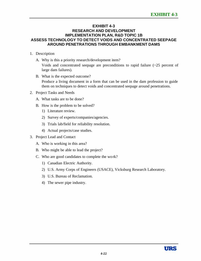
EXHIBIT 4-3
EXHIBIT 4-3 RESEARCH AND DEVELOPMENT
IMPLEMENTATION PLAN, R&D TOPIC 1B ASSESS TECHNOLOGY TO DETECT VOIDS AND CONCENTRATED SEEPAGE
AROUND PENETRATIONS THROUGH EMBANKMENT DAMS
1. Description
A. Why is this a priority research/development item? Voids and concentrated seepage are preconditions to rapid failure (~25 percent of large dam failures).
B. What is the expected outcome? Produce a living document in a form that can be used in the dam profession to guide them on techniques to detect voids and concentrated seepage around penetrations.
2. Project Tasks and Needs
A. What tasks are to be done?
B. How is the problem to be solved? 1) Literature review.
2) Survey of experts/companies/agencies.
3) Trials lab/field for reliability resolution.
4) Actual projects/case studies.
3. Project Lead and Contact
A. Who is working in this area?
B. Who might be able to lead the project?
C. Who are good candidates to complete the wo rk?
1) Canadian Electric Authority.
2) U.S. Army Corps of Engineers (USACE), Vicksburg Research Laboratory.
3) U.S. Bureau of Reclamation.
4) The sewer pipe industry.
4-22
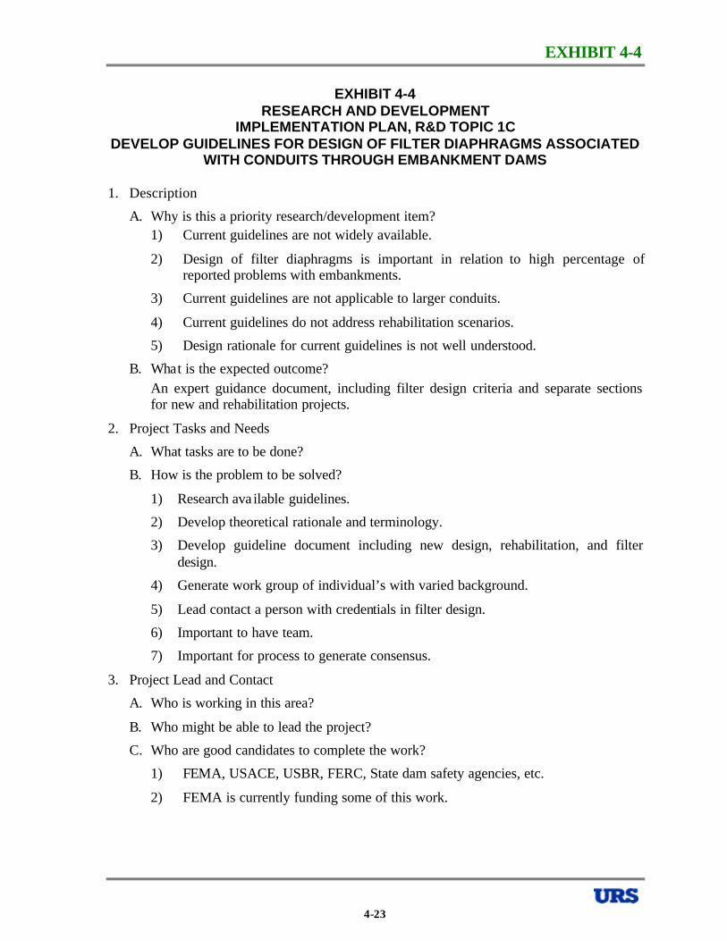
EXHIBIT 4-4
EXHIBIT 4-4 RESEARCH AND DEVELOPMENT
IMPLEMENTATION PLAN, R&D TOPIC 1C DEVELOP GUIDELINES FOR DESIGN OF FILTER DIAPHRAGMS ASSOCIATED
WITH CONDUITS THROUGH EMBANKMENT DAMS
1. Description
A. Why is this a priority research/development item? 1) Current guidelines are not widely available.
2) Design of filter diaphragms is important in relation to high percentage of reported problems with embankments.
3) Current guidelines are not applicable to larger conduits.
4) Current guidelines do not address rehabilitation scenarios.
5) Design rationale for current guidelines is not well understood.
B. Wha t is the expected outcome? An expert guidance document, including filter design criteria and separate sections for new and rehabilitation projects.
2. Project Tasks and Needs
A. What tasks are to be done?
B. How is the problem to be solved?
1) Research ava ilable guidelines.
2) Develop theoretical rationale and terminology.
3) Develop guideline document including new design, rehabilitation, and filter design.
4) Generate work group of individual’s with varied background.
5) Lead contact a person with credentials in filter design.
6) Important to have team.
7) Important for process to generate consensus.
3. Project Lead and Contact
A. Who is working in this area?
B. Who might be able to lead the project?
C. Who are good candidates to complete the work?
1) FEMA, USACE, USBR, FERC, State dam safety agencies, etc.
2) FEMA is currently funding some of this work.
4-23
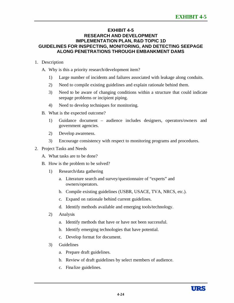
EXHIBIT 4-5
EXHIBIT 4-5 RESEARCH AND DEVELOPMENT
IMPLEMENTATION PLAN, R&D TOPIC 1D GUIDELINES FOR INSPECTING, MONITORING, AND DETECTING SEEPAGE
ALONG PENETRATIONS THROUGH EMBANKMENT DAMS
1. Description
A. Why is this a priority research/development item?
1) Large number of incidents and failures associated with leakage along conduits.
2) Need to compile existing guidelines and explain rationale behind them.
3) Need to be aware of changing conditions within a structure that could indicate seepage problems or incipient piping.
4) Need to develop techniques for monitoring.
B. What is the expected outcome?
1) Guidance document – audience includes designers, operators/owners and government agencies.
2) Develop awareness.
3) Encourage consistency with respect to monitoring programs and procedures.
2. Project Tasks and Needs
A. What tasks are to be done?
B. How is the problem to be solved?
1) Research/data gathering
a. Literature search and survey/questionnaire of “experts” and owners/operators.
b. Compile existing guidelines (USBR, USACE, TVA, NRCS, etc.).
c. Expand on rationale behind current guidelines.
d. Identify methods available and emerging tools/technology.
2) Analysis
a. Identify methods that have or have not been successful.
b. Identify emerging technologies that have potential.
c. Develop format for document.
3) Guidelines
a. Prepare draft guidelines.
b. Review of draft guidelines by select members of audience.
c. Fina lize guidelines.
4-24

EXHIBIT 4-5
EXHIBIT 4-5 RESEARCH AND DEVELOPMENT
IMPLEMENTATION PLAN, R&D TOPIC 1D GUIDELINES FOR INSPECTING, MONITORING, AND DETECTING SEEPAGE
ALONG PENETRATIONS THROUGH EMBANKMENT DAMS -CONTINUED
3. Project Lead and Contact
A. Who is working in this area?
B. Who might be able to lead the project?
C. Who are good candidates to complete the work?
1) USBR, NRCS, USACE, ASDSO, some states, large owners/operators.
2) University/Academic – MS or Ph.D. thesis, sponsored research (i.e., through ASDSO or USCOLD [USSD] scholarship programs).
3) FEMA is currently funding some of this work through the federal agencies and ASDSO.
4-25
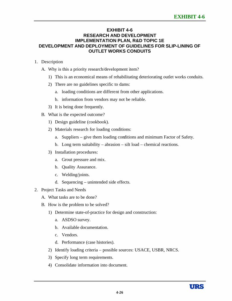
EXHIBIT 4-6
EXHIBIT 4-6 RESEARCH AND DEVELOPMENT
IMPLEMENTATION PLAN, R&D TOPIC 1E DEVELOPMENT AND DEPLOYMENT OF GUIDELINES FOR SLIP-LINING OF
OUTLET WORKS CONDUITS
1. Description
A. Why is this a priority research/development item?
1) This is an economical means of rehabilitating deteriorating outlet works conduits.
2) There are no guidelines specific to dams:
a. loading conditions are different from other applications.
b. information from vendors may not be reliable.
3) It is being done frequently.
B. What is the expected outcome?
1) Design guideline (cookbook).
2) Materials research for loading conditions:
a. Suppliers – give them loading conditions and minimum Factor of Safety.
b. Long term suitability – abrasion – silt load – chemical reactions.
3) Installation procedures:
a. Grout pressure and mix.
b. Quality Assurance.
c. Welding/joints.
d. Sequencing – unintended side effects.
2. Project Tasks and Needs
A. What tasks are to be done?
B. How is the problem to be solved?
1) Determine state-of-practice for design and construction:
a. ASDSO survey.
b. Available documentation.
c. Vendors.
d. Performance (case histories).
2) Identify loading criteria – possible sources: USACE, USBR, NRCS.
3) Specify long term requirements.
4) Consolidate information into document.
4-26
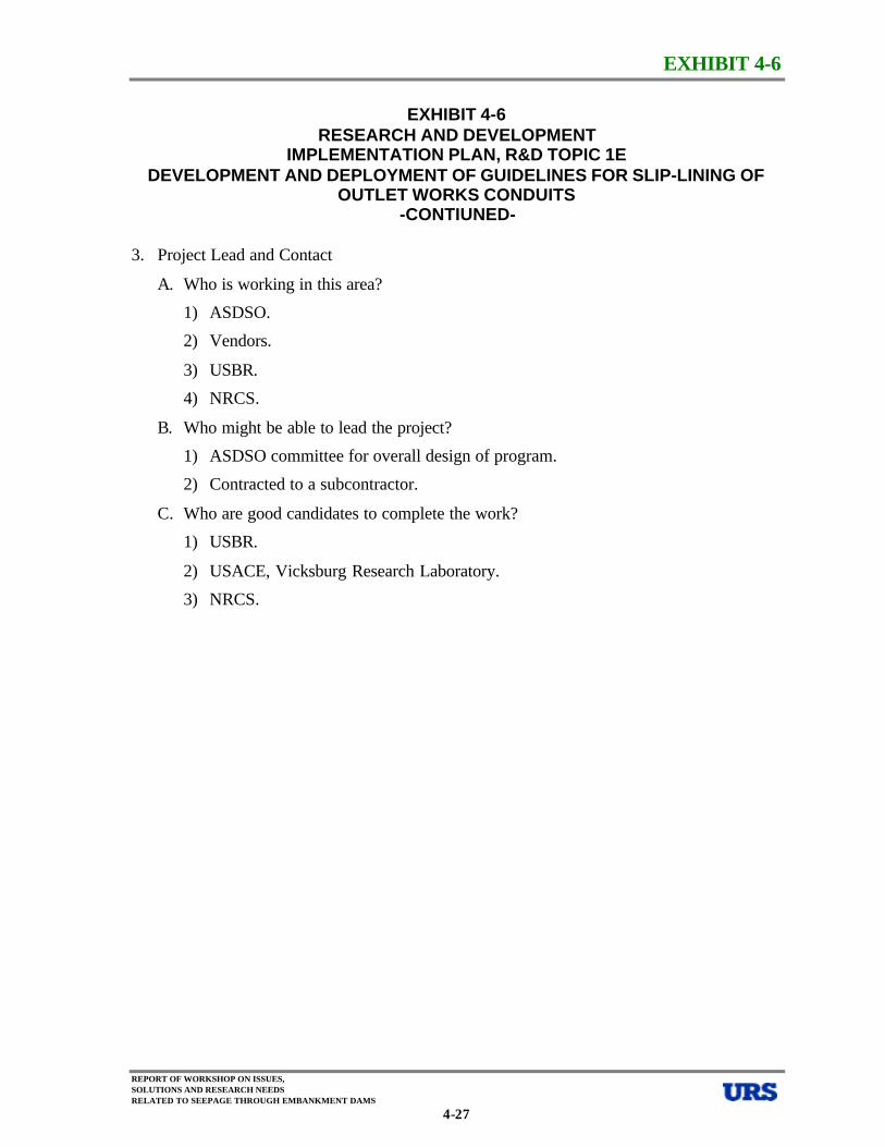
EXHIBIT 4-6
EXHIBIT 4-6 RESEARCH AND DEVELOPMENT
IMPLEMENTATION PLAN, R&D TOPIC 1E DEVELOPMENT AND DEPLOYMENT OF GUIDELINES FOR SLIP-LINING OF
OUTLET WORKS CONDUITS -CONTIUNED
3. Project Lead and Contact
A. Who is working in this area?
1) ASDSO.
2) Vendors.
3) USBR.
4) NRCS.
B. Who might be able to lead the project?
1) ASDSO committee for overall design of program.
2) Contracted to a subcontractor.
C. Who are good candidates to complete the work?
1) USBR.
2) USACE, Vicksburg Research Laboratory.
3) NRCS.
REPORT OF WORKSHOP ON ISSUES, SOLUTIONS AND RESEARCH NEEDS RELATED TO SEEPAGE THROUGH EMBANKMENT DAMS
4-27
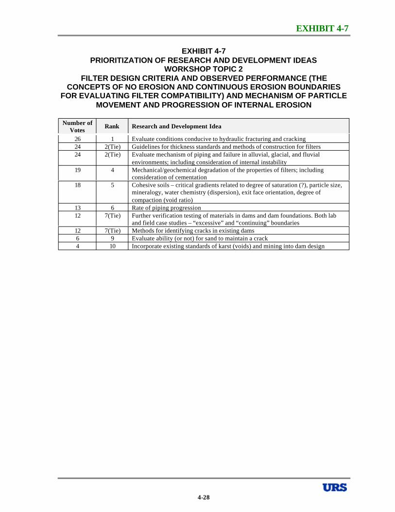
EXHIBIT 4-7
EXHIBIT 4-7 PRIORITIZATION OF RESEARCH AND DEVELOPMENT IDEAS
WORKSHOP TOPIC 2 FILTER DESIGN CRITERIA AND OBSERVED PERFORMANCE (THE
CONCEPTS OF NO EROSION AND CONTINUOUS EROSION BOUNDARIES FOR EVALUATING FILTER COMPATIBILITY) AND MECHANISM OF PARTICLE
MOVEMENT AND PROGRESSION OF INTERNAL EROSION
Number of Votes
Rank Research and Development Idea
26 1 Evaluate conditions conducive to hydraulic fracturing and cracking 24 2(Tie) Guidelines for thickness standards and methods of construction for filters 24 2(Tie) Evaluate mechanism of piping and failure in alluvial, glacial, and fluvial
environments; including consideration of internal instability 19 4 Mechanical/geochemical degradation of the properties of filters; including
consideration of cementation 18 5 Cohesive soils – critical gradients related to degree of saturation (?), particle size,
mineralogy, water chemistry (dispersion), exit face orientation, degree of compaction (void ratio)
13 6 Rate of piping progression 12 7(Tie) Further verification testing of materials in dams and dam foundations. Both lab
and field case studies – “excessive” and “continuing” boundaries 12 7(Tie) Methods for identifying cracks in existing dams 6 9 Evaluate ability (or not) for sand to maintain a crack 4 10 Incorporate existing standards of karst (voids) and mining into dam design
4-28
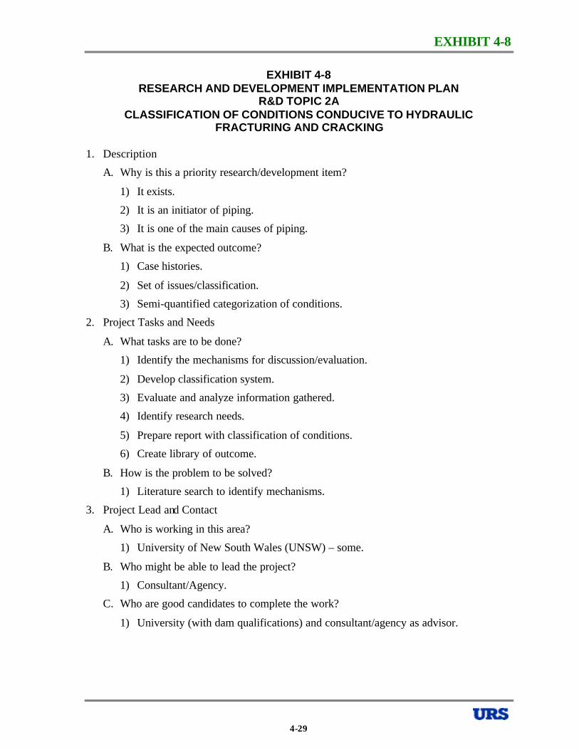
EXHIBIT 4-8
EXHIBIT 4-8 RESEARCH AND DEVELOPMENT IMPLEMENTATION PLAN
R&D TOPIC 2A CLASSIFICATION OF CONDITIONS CONDUCIVE TO HYDRAULIC
FRACTURING AND CRACKING
1. Description
A. Why is this a priority research/development item?
1) It exists.
2) It is an initiator of piping.
3) It is one of the main causes of piping.
B. What is the expected outcome?
1) Case histories.
2) Set of issues/classification.
3) Semi-quantified categorization of conditions.
2. Project Tasks and Needs
A. What tasks are to be done?
1) Identify the mechanisms for discussion/evaluation.
2) Develop classification system.
3) Evaluate and analyze information gathered.
4) Identify research needs.
5) Prepare report with classification of conditions.
6) Create library of outcome.
B. How is the problem to be solved?
1) Literature search to identify mechanisms.
3. Project Lead and Contact
A. Who is working in this area?
1) University of New South Wales (UNSW) – some.
B. Who might be able to lead the project?
1) Consultant/Agency.
C. Who are good candidates to complete the work?
1) University (with dam qualifications) and consultant/agency as advisor.
4-29
EXHIBIT 4-9
EXHIBIT 4-9 RESEARCH AND DEVELOPMENT IMPLEMENTATION PLAN
R&D TOPIC 2B DEVELOP STATE-OF-THE-PRACTICE FOR CONFIGURATIONS, DIMENSIONS,
AND CONSTRUCTION METHODS FOR FILTERS AND DRAINS 1. Description
A. Why is this a priority research/development item?
1) Lack of consensus.
2) They are critical design, construction and cost elements in dams.
B. What is the expected outcome?
1) A summary document of the state-of-the-practice, with recommendations for minimum thickness, construction techniques, quality assurance, and dimension limits within the dam.
2. Project Tasks and Needs
A. What tasks are to be done?
B. How is the problem to be solved?
1) Survey of practices by institutions, companies, agencies, and other countries.
2) Evaluate performance, case histories, and incidents.
3) Develop rationale for configuration and design layout.
4) Develop rationale for minimum thicknesses for design and constructability for horizontal, vertical, inclined, and finger drains and filters.
3. Project Lead and Contact
A. Who is working in this area?
B. Who might be able to lead the project?
C. Who are good candidates to complete the work?
1) USACE, USBR, NRCS, TVA.
2) ASDSO Committee.
3) University group.
4) Consultants.
4-30
EXHIBIT 4-10
EXHIBIT 4-10 RESEARCH AND DEVELOPMENT IMPLEMENTATION PLAN
R&D TOPIC 2C EVALUATE MECHANISM OF PIPING AND FAILURE IN GLACIAL, ALLUVIAL,
AND FLUVIAL ENVIRONMENTS – INCLUDING CONSIDERATION OF INTERNAL INSTABILITY
1. Description
A. Why is this a priority research/development item?
1) Mechanisms are poorly understood.
2) These geologic environments are fairly common.
3) Many case histories suggest that these conditions are not highly conducive to piping failures, but the reason for this is not clear.
B. What is the expected outcome?
1) Some conclusions regarding the conditions under which these geologic environments do or do not present a serious risk of piping failure.
2) Recommendations on how to address piping concerns in these geologic environments when concerns do exist.
3) A compendium of case histories of failures, incidents, and non-failures.
2. Project Tasks and Needs
A. What tasks are to be done?
1) Survey State dam safety officials and other sources for case histories, both published and unpublished.
2) Contact individuals and organizations with experience in these types of environments (e.g., Ralph Peck, Norbert Morgenstern, BC Hydro) to understand their interpretation of piping risks posed by the specific geologic environments (why do they not lose sleep at night in some cases with significant foundation seepage?).
B. How is the problem to be solved?
1) Screen case histories for selected cases that will be further studied in-depth, perhaps with field investigations.
4-31

EXHIBIT 4-10
EXHIBIT 4-10 RESEARCH AND DEVELOPMENT IMPLEMENTATION PLAN
R&D TOPIC 2C EVALUATE MECHANISM OF PIPING AND FAILURE IN GLACIAL, ALLUVIAL,
AND FLUVIAL ENVIRONMENTS – INCLUDING CONSIDERATION OF INTERNAL INSTABILITY -CONTINUED
3. Project Lead and Contact
A. Who is working in this area?
1) USACE.
2) USBR.
3) NRCS.
4) Hydro-Quebec, Canada.
5) Ontario Hydro, Canada.
6) BC Hydro, Canada.
7) Vattenfall, Sweden.
B. Who might be able to lead the project?
1) A professor with access to multidiscipline graduate students (geology and engineering).
2) Supported by advisors from practice, with expertise in geology and dam design/performance.
3) Possibly a lead agency with support from other agencies (multidiscipline effort).
C. Who are good candidates to complete the work?
1) Utah State University.
2) University of Vancouver.
3) Virginia Polytechnical University.
4) University of New South Wales.
5) Consultants or Consulting Companies.
4-32
EXHIBIT 4-11
EXHIBIT 4-11 RESEARCH AND DEVELOPMENT IMPLEMENTATION PLAN
R&D TOPIC 2D EVALUATION OF MECHANICAL/GEOCHEMICAL DEGRADATION OF
PROPERTIES OF FILTER MATERIALS, INCLUDING CEMENTATION AND THEIR ABILITY TO SUSTAIN A CRACK
1. Description
A. Why is this a priority research/development item?
1) Critical part of any dam.
2) Dams are aging.
3) We are seeing filters plugging up.
4) Case histories of problems are occurring.
B. What is the expected outcome?
1) Identify materials for future design and remediation.
2) Identify potential problem materials in existing dams.
2. Project Tasks and Needs
A. What tasks are to be done?
B. How is the problem to be solved?
1) Identify mechanisms of degradation/cracking etc.
2) Review existing filter performance.
3) Lab testing for effects of fines, plasticity index, chemical alteration, etc.
4) Evaluate/identify possible in situ testing.
5) Field investigation.
6) Identify types of remediation.
3. Project Lead and Contact
A. Who is working in this area?
B. Who might be able to lead the project?
C. Who are good candidates to complete the work?
1) Government agencies.
2) University research centers.
4-33
EXHIBIT 4-12
EXHIBIT 4-12 RESEARCH AND DEVELOPMENT IMPLEMENTATION PLAN
R&D TOPIC 2E THRESHOLD GRADIENTS FOR INITIATING PIPING IN COHESIVE SOILS
1. Description
A. Why is this a priority research/development item?
1) Important for evaluation of older dams with “incorrect filters” or no filters.
2) Possible applicability to small dams.
3) Key first step in understanding piping process.
B. What is the expected outcome?
1) Determine if there really is a threshold gradient.
2) Test results relating threshold gradient to physical properties.
2. Project Tasks and Needs
A. What tasks are to be done?
B. How is the problem to be solved?
1) Literature research.
2) Test design.
3) Lab testing.
4) Correlation with case histories.
5) Report of findings.
3. Project Lead and Contact
A. Who is working in this area?
B. Who might be able to lead the project?
C. Who are good candidates to complete the work?
1) No known activity at present time.
2) Lead – Agency or University with substantial lab resources.
3) Specific good candidates:
USACE- Vicksburg Research Laboratory, NRCS, USBR, Universities.
4-34
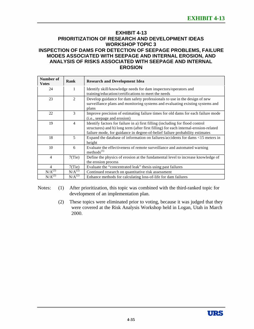
EXHIBIT 4-13
EXHIBIT 4-13 PRIORITIZATION OF RESEARCH AND DEVELOPMENT IDEAS
WORKSHOP TOPIC 3 INSPECTION OF DAMS FOR DETECTION OF SEEPAGE PROBLEMS, FAILURE
MODES ASSOCIATED WITH SEEPAGE AND INTERNAL EROSION, AND ANALYSIS OF RISKS ASSOCIATED WITH SEEPAGE AND INTERNAL
EROSION
Number of Votes
Rank Research and Development Idea
24 1 Identify skill/knowledge needs for dam inspectors/operators and training/education/certifications to meet the needs
23 2 Develop guidance for dam safety professionals to use in the design of new surveillance plans and monitoring systems and evaluating existing systems and plans
22 3 Improve precision of estimating failure times for old dams for each failure mode (i.e., seepage and erosion)
19 4 Identify factors for failure in a) first filling (including for flood control structures) and b) long term (after first filling) for each internal-erosion-related failure mode, for guidance in degree-of-belief failure probability estimates
18 5 Expand the database of information on failures/accidents for dams <15 meters in height
10 6 Evaluate the effectiveness of remote surveillance and automated warning methods(1)
4 7(Tie) Define the physics of erosion at the fundamental level to increase knowledge of the erosion process
4 7(Tie) Evaluate the “concentrated leak” thesis using past failures N/A(2) N/A(2) Continued research on quantitative risk assessment N/A(2) N/A(2) Enhance methods for calculating loss-of-life for dam failures
Notes: (1) After prioritization, this topic was combined with the third-ranked topic for development of an implementation plan.
(2) These topics were eliminated prior to voting, because it was judged that they were covered at the Risk Analysis Workshop held in Logan, Utah in March 2000.
4-35
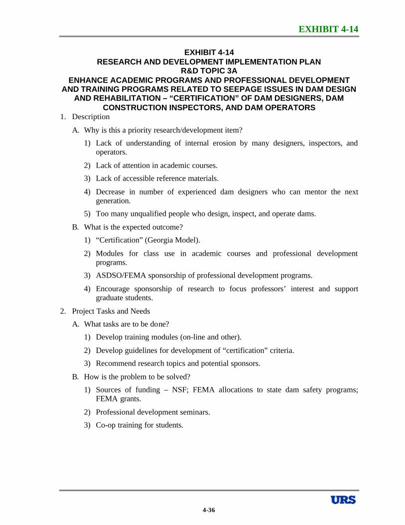
EXHIBIT 4-14
EXHIBIT 4-14 RESEARCH AND DEVELOPMENT IMPLEMENTATION PLAN
R&D TOPIC 3A ENHANCE ACADEMIC PROGRAMS AND PROFESSIONAL DEVELOPMENT
AND TRAINING PROGRAMS RELATED TO SEEPAGE ISSUES IN DAM DESIGN AND REHABILITATION – “CERTIFICATION” OF DAM DESIGNERS, DAM
CONSTRUCTION INSPECTORS, AND DAM OPERATORS 1. Description
A. Why is this a priority research/development item?
1) Lack of understanding of internal erosion by many designers, inspectors, and operators.
2) Lack of attention in academic courses.
3) Lack of accessible reference materials.
4) Decrease in number of experienced dam designers who can mentor the next generation.
5) Too many unqualified people who design, inspect, and operate dams.
B. What is the expected outcome?
1) “Certification” (Georgia Model).
2) Modules for class use in academic courses and professional development programs.
3) ASDSO/FEMA sponsorship of professional development programs.
4) Encourage sponsorship of research to focus professors’ interest and support graduate students.
2. Project Tasks and Needs
A. What tasks are to be done?
1) Develop training modules (on-line and other).
2) Develop guidelines for development of “certification” criteria.
3) Recommend research topics and potential sponsors.
B. How is the problem to be solved?
1) Sources of funding – NSF; FEMA allocations to state dam safety programs; FEMA grants.
2) Professional development seminars.
3) Co-op training for students.
4-36
EXHIBIT 4-14
EXHIBIT 4-14 RESEARCH AND DEVELOPMENT IMPLEMENTATION PLAN
R&D TOPIC 3A ENHANCE ACADEMIC PROGRAMS AND PROFESSIONAL DEVELOPMENT
AND TRAINING PROGRAMS RELATED TO SEEPAGE ISSUES IN DAM DESIGN AND REHABILITATION – “CERTIFICATION” OF DAM DESIGNERS, DAM
CONSTRUCTION INSPECTORS, AND DAM OPERATORS -CONTINUED
3. Project Lead and Contact
A. Who is working in this area?
1) TADS program.
B. Who might be able to lead the project?
1) Loren Anderson
2) Mike Duncan
3) Jim Wright
4) Larry Von Thun
C. Who are good candidates to complete the work?
1) Loren Anderson
2) Mike Duncan
3) Jim Wright
4) Larry Von Thun
4-37
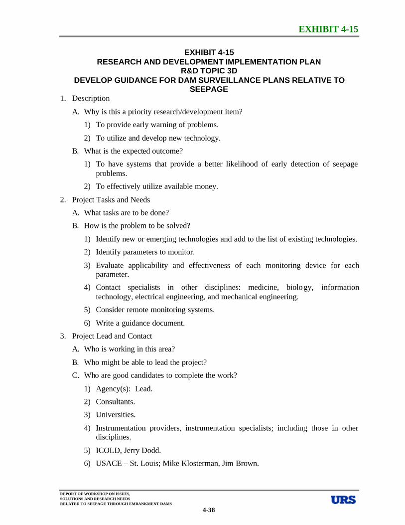
EXHIBIT 4-15
EXHIBIT 4-15 RESEARCH AND DEVELOPMENT IMPLEMENTATION PLAN
R&D TOPIC 3D DEVELOP GUIDANCE FOR DAM SURVEILLANCE PLANS RELATIVE TO
SEEPAGE 1. Description
A. Why is this a priority research/development item?
1) To provide early warning of problems.
2) To utilize and develop new technology.
B. What is the expected outcome?
1) To have systems that provide a better likelihood of early detection of seepage problems.
2) To effectively utilize available money.
2. Project Tasks and Needs
A. What tasks are to be done?
B. How is the problem to be solved?
1) Identify new or emerging technologies and add to the list of existing technologies.
2) Identify parameters to monitor.
3) Evaluate applicability and effectiveness of each monitoring device for each parameter.
4) Contact specialists in other disciplines: medicine, biolo gy, information technology, electrical engineering, and mechanical engineering.
5) Consider remote monitoring systems.
6) Write a guidance document.
3. Project Lead and Contact
A. Who is working in this area?
B. Who might be able to lead the project?
C. Who are good candidates to complete the work?
1) Agency(s): Lead.
2) Consultants.
3) Universities.
4) Instrumentation providers, instrumentation specialists; including those in other disciplines.
5) ICOLD, Jerry Dodd.
6) USACE – St. Louis; Mike Klosterman, Jim Brown.
REPORT OF WORKSHOP ON ISSUES, SOLUTIONS AND RESEARCH NEEDS RELATED TO SEEPAGE THROUGH EMBANKMENT DAMS
4-38
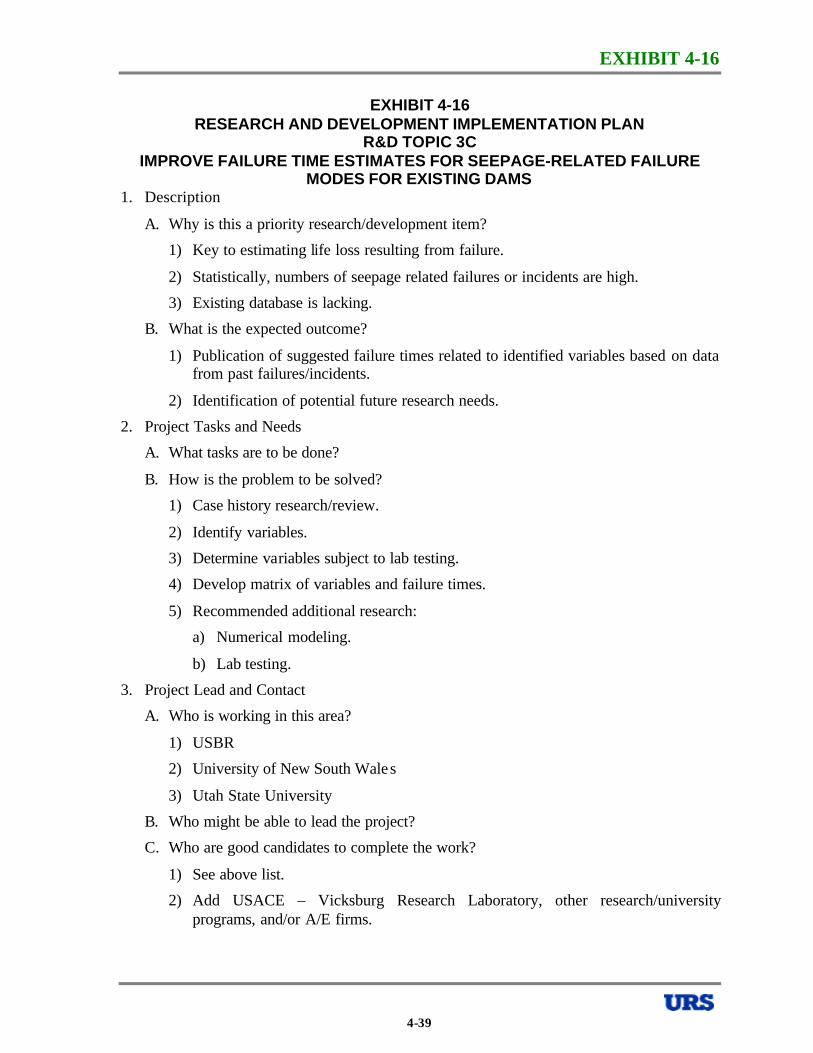
EXHIBIT 4-16
EXHIBIT 4-16 RESEARCH AND DEVELOPMENT IMPLEMENTATION PLAN
R&D TOPIC 3C IMPROVE FAILURE TIME ESTIMATES FOR SEEPAGE-RELATED FAILURE
MODES FOR EXISTING DAMS 1. Description
A. Why is this a priority research/development item?
1) Key to estimating life loss resulting from failure.
2) Statistically, numbers of seepage related failures or incidents are high.
3) Existing database is lacking.
B. What is the expected outcome?
1) Publication of suggested failure times related to identified variables based on data from past failures/incidents.
2) Identification of potential future research needs.
2. Project Tasks and Needs
A. What tasks are to be done?
B. How is the problem to be solved?
1) Case history research/review.
2) Identify variables.
3) Determine variables subject to lab testing.
4) Develop matrix of variables and failure times.
5) Recommended additional research:
a) Numerical modeling.
b) Lab testing.
3. Project Lead and Contact
A. Who is working in this area?
1) USBR
2) University of New South Wale s
3) Utah State University
B. Who might be able to lead the project?
C. Who are good candidates to complete the work?
1) See above list.
2) Add USACE – Vicksburg Research Laboratory, other research/university programs, and/or A/E firms.
4-39
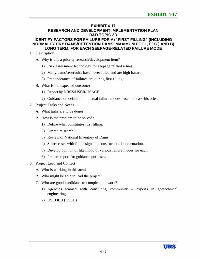
EXHIBIT 4-17
EXHIBIT 4-17 RESEARCH AND DEVELOPMENT IMPLEMENTATION PLAN
R&D TOPIC 3D IDENTIFY FACTORS FOR FAILURE FOR A) “FIRST FILLING” (INCLUDING
NORMALLY DRY DAMS/DETENTION DAMS, MAXIMUM POOL, ETC.) AND B) LONG TERM, FOR EACH SEEPAGE-RELATED FAILURE MODE
1. Description
A. Why is this a priority research/development item?
1) Risk assessment technology for seepage related issues.
2) Many dams/reservoirs have never filled and are high hazard.
3) Preponderance of failures are during first filling.
B. What is the expected outcome?
1) Report by NRCS/USBR/USACE.
2) Guidance on definition of actual failure modes based on case histories.
2. Project Tasks and Needs
A. What tasks are to be done?
B. How is the problem to be solved?
1) Define what constitutes first filling.
2) Literature search.
3) Review of National Inventory of Dams.
4) Select cases with full design and construction documentation.
5) Develop opinion of likelihood of various failure modes for each.
6) Prepare report for guidance purposes.
3. Project Lead and Contact
A. Who is working in this area?
B. Who might be able to lead the project?
C. Who are good candidates to complete the work?
1) Agencies teamed with consulting community – experts in geotechnical engineering.
2) USCOLD (USSD)
4-40
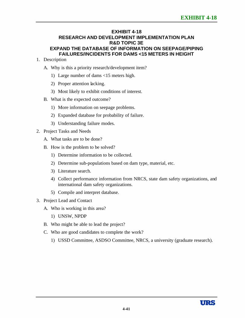
EXHIBIT 4-18
EXHIBIT 4-18 RESEARCH AND DEVELOPMENT IMPLEMENTATION PLAN
R&D TOPIC 3E EXPAND THE DATABASE OF INFORMATION ON SEEPAGE/PIPING
FAILURES/INCIDENTS FOR DAMS <15 METERS IN HEIGHT 1. Description
A. Why is this a priority research/development item?
1) Large number of dams <15 meters high.
2) Proper attention lacking.
3) Most likely to exhibit conditions of interest.
B. What is the expected outcome?
1) More information on seepage problems.
2) Expanded database for probability of failure.
3) Understanding failure modes.
2. Project Tasks and Needs
A. What tasks are to be done?
B. How is the problem to be solved?
1) Determine information to be collected.
2) Determine sub-populations based on dam type, material, etc.
3) Literature search.
4) Collect performance information from NRCS, state dam safety organizations, and international dam safety organizations.
5) Compile and interpret database.
3. Project Lead and Contact
A. Who is working in this area?
1) UNSW, NPDP
B. Who might be able to lead the project?
C. Who are good candidates to complete the work?
1) USSD Committee, ASDSO Committee, NRCS, a university (graduate research).
4-41
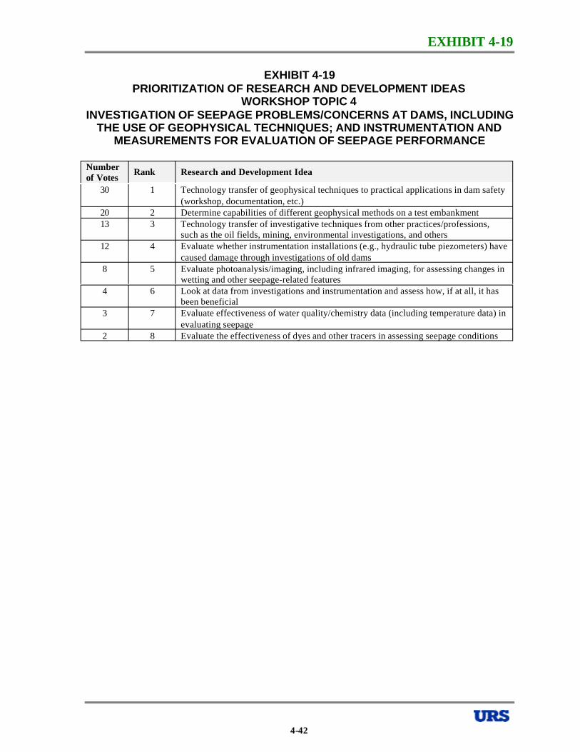
EXHIBIT 4-19
EXHIBIT 4-19 PRIORITIZATION OF RESEARCH AND DEVELOPMENT IDEAS
WORKSHOP TOPIC 4 INVESTIGATION OF SEEPAGE PROBLEMS/CONCERNS AT DAMS, INCLUDING
THE USE OF GEOPHYSICAL TECHNIQUES; AND INSTRUMENTATION AND MEASUREMENTS FOR EVALUATION OF SEEPAGE PERFORMANCE
Number of Votes
Rank Research and Development Idea
30 1 Technology transfer of geophysical techniques to practical applications in dam safety (workshop, documentation, etc.)
20 2 Determine capabilities of different geophysical methods on a test embankment 13 3 Technology transfer of investigative techniques from other practices/professions,
such as the oil fields, mining, environmental investigations, and others 12 4 Evaluate whether instrumentation installations (e.g., hydraulic tube piezometers) have
caused damage through investigations of old dams 8 5 Evaluate photoanalysis/imaging, including infrared imaging, for assessing changes in
wetting and other seepage-related features 4 6 Look at data from investigations and instrumentation and assess how, if at all, it has
been beneficial 3 7 Evaluate effectiveness of water quality/chemistry data (including temperature data) in
evaluating seepage 2 8 Evaluate the effectiveness of dyes and other tracers in assessing seepage conditions
4-42
EXHIBIT 4-20
EXHIBIT 4-20 RESEARCH AND DEVELOPMENT IMPLEMENTATION PLAN
R&D TOPIC 4A TECHNOLOGY TRANSFER OF GEOPHYSICAL TECHNIQUES FOR SEEPAGE
MONITORING 1. Description
A. Why is this a priority research/development item?
1) Lack of communication between geophysicists and geotechnical engineers.
2) Potentially useful, noninvasive, economical, quick, efficient tools/techniques.
3) Potential capabilities of techniques are not understood by geotechnical community.
B. What is the expected outcome?
1) Workshop with proceedings; attended by geotechnical and geophysics practitioners.
2) Guidance document for use of techniques.
2. Project Tasks and Needs
A. What tasks are to be done?
B. How is the problem to be solved?
1) Organize workshop.
2) Literature search.
3) Compile selected short list of topics for workshop, based on interest of community.
4) Geophysicists presentation of capabilities and case histories; positives and negatives.
5) Geotechnical practitioners’ presentation of needs and case histories.
6) Compile comprehensive comparison; pros and cons.
7) Prepare guidance document for techniques, and disseminate.
8) Possibly combine with test embankment.
4-43
EXHIBIT 4-20
EXHIBIT 4-20 RESEARCH AND DEVELOPMENT IMPLEMENTATION PLAN
R&D TOPIC 4A TECHNOLOGY TRANSFER OF GEOPHYSICAL TECHNIQUES FOR SEEPAGE
MONITORING -CONTINUED
3. Project Lead and Contact
A. Who is working in this area?
B. Who might be able to lead the project?
C. Who are good candidates to complete the work?
1) ASDSO/FEMA.
2) ASTM.
3) Ken Stokee, University of Texas at Austin.
4) ASCE.
5) USBR.
6) USACE.
7) USGS.
8) Carlos Santamarina, Georgia Tech.
9) Bob Whitley.
10) James Bay, Student at Utah State University
4-44

EXHIBIT 4-21
EXHIBIT 4-21 RESEARCH AND DEVELOPMENT IMPLEMENTATION PLAN
R&D TOPIC 4B TEST CAPABILITIES OF DIFFERENT GEOPHYSICAL METHODS ON A TEST
EMBANKMENT 1. Description
A. Why is this a priority research/development item?
1) Engineers are skeptical.
2) Benefits are large, if the methods are proven.
3) Need to establish limitations and expectations.
4) Non-intrusive, no damage.
B. What is the expected outcome?
1) Provide confidence.
2) Improved understanding of applications and limitations.
3) Weed out ineffective techniques.
4) Document (report) findings from engineers’ perspective.
2. Project Tasks and Needs
A. What tasks are to be done?
B. How is the problem to be solved?
1) Design test fill; modeling defects, e.g., voids, loose zones, cracks, etc.
2) Research and select methods.
3) Define performance criteria (what is success?).
4) Construct and characterize test fill.
5) Perform geophysical tests and interpret results.
6) Evaluate all methods, and report.
3. Project Lead and Contact
A. Who is working in this area?
1) CEA (Canadian Electric Association).
2) USBR.
3) USACE.
4) BC Hydro.
5) Cons ultants.
6) Geophysicists.
4-45
EXHIBIT 4-21
EXHIBIT 4-21 RESEARCH AND DEVELOPMENT IMPLEMENTATION PLAN
R&D TOPIC 4B TEST CAPABILITIES OF DIFFERENT GEOPHYSICAL METHODS ON A TEST
EMBANKMENT -CONTINUED
B. Who might be able to lead the project?
1) CEA.
2) USBR.
3) BC Hydro.
4) NRCS.
C. Who are good candidates to complete the work?
1) Contractors/geophysicist.
2) Universities.
3) Consultants.
4) Equipment manufacturers/suppliers.
4-46
EXHIBIT 4-22
EXHIBIT 4-22 RESEARCH AND DEVELOPMENT IMPLEMENTATION PLAN
R&D TOPIC 4C CROSS-DISCIPLINE TECHNOLOGY TRANSFER FOR INVESTIGATIVE
TECHNIQUES IN DAMS 1. Description
A. Why is this a priority research/development item?
1) Limited available technology for seepage investigation.
2) There may be advances in other industries that could be used to detect seepage in dams; these other industries include DOD (Department of Defense), oil fields, intelligence, etc.
B. What is the expected outcome?
1) Identification of existing methods and technologies applicable to seepage investigations.
2. Project Tasks and Needs
A. What tasks are to be done?
B. How is the problem to be solved?
1) Establish list of parameters/features that need to be identified, measured, monitored, etc. (e.g., seepage/water movement, voids, temperature, interface conditions, velocities, water pressure, void ratio, etc.).
2) Review of literature/ prior studies that may have been done for dams.
3) Identify potential techniques in other industries.
4) Evaluate identified techniques for their suitability, feasibility, effectiveness, etc. for the items established in (1).
5) Develop a report summarizing findings.
3. Project Lead and Contact
A. Who is working in this area?
1) This is the objective of the study, to identify others having potential applications.
B. Who might be able to lead the project?
1) ASDSO.
C. Who are good candidates to complete the work?
1) Someone like Carlos Santamarina at Georgia Tech.
4-47
EXHIBIT 4-23
EXHIBIT 4-23 RESEARCH AND DEVELOPMENT IMPLEMENTATION PLAN
R&D TOPIC 4D DO/CAN INSTRUMENTS OR INSTRUMENT INSTALLATIONS CAUSE DAMAGE
IN EMBANKMENT DAMS 1. Description
A. Why is this a priority research/development item?
1) Concern that instrument installations can be a source of seepage and potential internal erosion.
2) May be a gradually deteriorating problem.
B. What is the expected outcome?
1) Conclusion if there are problems, and, if so, what is the timeframe in which we expect they manifest themselves.
2. Project Tasks and Needs
A. What tasks are to be done?
B. How is the problem to be solved?
1) Survey dam owners, state representatives, consultant s, and federal agencies for instrumentation problems (i.e., when did they stop working, did seepage problem occur, etc.).
2) Correlate the time the problems occurred vs. type of instruments.
3) Identify remedial measures that might be useful.
4) Categorize instruments – record locations, head on the instruments etc., types of instruments that could be a problem.
5) Contact material suppliers about nature of plastic tubing, etc.
3. Project Lead and Contact
A. Who is working in this area?
1) No one is specifically working in this area.
B. Who might be able to lead the project?
C. Who are good candidates to complete the work?
1) USACE.
2) USBR.
3) ASDSO.
4) State of California, Department of Water Resources.
4-48
EXHIBIT 4-24
EXHIBIT 4-24 RESEARCH AND DEVELOPMENT IMPLEMENTATION PLAN
R&D TOPIC 4E ASSESS PHOTO-MONITORING TECHNIQUES FOR SEEPAGE (INFRARED
IMAGING, PHOTO INTERPRETATION, ETC.) 1. Description
A. Why is this a priority research/development item?
1) Low cost method.
2) Long term monitoring technique.
3) Screening technique.
4) Early indicator of problems.
B. What is the expected outcome?
1) Overall assessment of value, with report.
2. Project Tasks and Needs
A. What tasks are to be done?
B. How is the problem to be solved?
1) Information search – USACE, DEA (Drug Enforcement Agency), USBR, JPL (Jet Propulsion Laboratory), NASA, TEC-Fort Belvoir.
2) Field calibration/testing of methods – comparison of results.
3) Summary report of information.
3. Project Lead and Contact
A. Who is working in this area?
1) Universities – Corne ll, Maine.
2) USBR.
3) USACE.
B. Who might be able to lead the project?
C. Who are good candidates to complete the work?
1) A university.
2) USBR.
3) USACE.
4-49
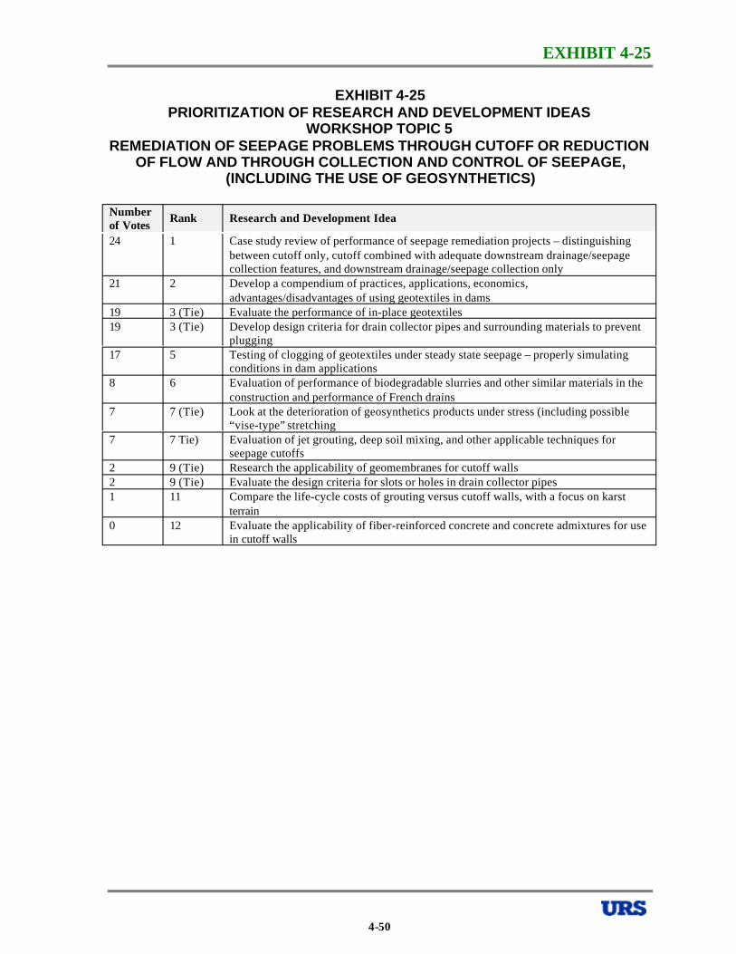
EXHIBIT 4-25
EXHIBIT 4-25 PRIORITIZATION OF RESEARCH AND DEVELOPMENT IDEAS
WORKSHOP TOPIC 5 REMEDIATION OF SEEPAGE PROBLEMS THROUGH CUTOFF OR REDUCTION
OF FLOW AND THROUGH COLLECTION AND CONTROL OF SEEPAGE, (INCLUDING THE USE OF GEOSYNTHETICS)
Number of Votes
Rank Research and Development Idea
24 1 Case study review of performance of seepage remediation projects – distinguishing between cutoff only, cutoff combined with adequate downstream drainage/seepage collection features, and downstream drainage/seepage collection only
21 2 Develop a compendium of practices, applications, economics, advantages/disadvantages of using geotextiles in dams
19 3 (Tie) Evaluate the performance of in-place geotextiles 19 3 (Tie) Develop design criteria for drain collector pipes and surrounding materials to prevent
plugging 17 5 Testing of clogging of geotextiles under steady state seepage – properly simulating
conditions in dam applications 8 6 Evaluation of performance of biodegradable slurries and other similar materials in the
construction and performance of French drains 7 7 (Tie) Look at the deterioration of geosynthetics products under stress (including possible
“vise-type” stretching 7 7 Tie) Evaluation of jet grouting, deep soil mixing, and other applicable techniques for
seepage cutoffs 2 9 (Tie) Research the applicability of geomembranes for cutoff walls 2 9 (Tie) Evaluate the design criteria for slots or holes in drain collector pipes 1 11 Compare the life-cycle costs of grouting versus cutoff walls, with a focus on karst
terrain 0 12 Evaluate the applicability of fiber-reinforced concrete and concrete admixtures for use
in cutoff walls
4-50
EXHIBIT 4-26
EXHIBIT 4-26 RESEARCH AND DEVELOPMENT IMPLEMENTATION PLAN
R&D TOPIC 5A REVIEW OF PERFORMANCE OF SEEPAGE REMEDIATION MEASURES: A) UPSTREAM CUTOFF ONLY, B) UPSTREAM CUTOFF WITH DOWNSTREAM
COLLECTION, AND C) DOWNSTREAM COLLECTION ONLY 1. Description
A. Why is this a priority research/development item?
1) Validate current design practice.
2) Reconcile existing disparity among practitioners regarding whether upstream cutoff alone is an appropriate remediation approach.
B. What is the expected outcome?
1) Recommended practice with compendium of case histories.
2. Project Tasks and Needs
A. What tasks are to be done?
B. How is the problem to be solved?
1) Literature search.
2) Canvas agencies, consultants, and owners.
3) Matrix of evaluation criteria: effectiveness, cost, constructability.
4) Collect cases and evaluate.
5) Prepare a guidance document.
3. Project Lead and Contact
A. Who is working in this area?
B. Who might be able to lead the project?
C. Who are good candidates to complete the work?
1) ASDSO (via university).
2) Practicing engineer as sponsor/advisor.
4-51
EXHIBIT 4-27
EXHIBIT 4-27 RESEARCH AND DEVELOPMENT IMPLEMENTATION PLAN
R&D TOPIC 5B COMPILATION OF PRACTICES, APPLICATIONS, EXPERIENCES, ECONOMICS,
AND ADVANTAGES/DISADVANTAGES OF USING GEOTEXTILES IN DAM APPLICATIONS
1. Description
A. Why is this a priority research/development item?
1) Geotextiles are being used in applications where perhaps they should not be.
2) Geotextiles are widely used in small, low hazard dams.
3) Among many practitioners, there is a strongly held view against geotextiles that may not be well based.
4) We may find appropriate applications that enhance performance.
B. What is the expected outcome?
1) Report to be widely disseminated.
2) Form basis of future guidelines and updates to existing practice.
3) Comparison of cost with conventional installation.
4) Compilation of case studies.
2. Project Tasks and Needs
A. What tasks are to be done?
B. How is the problem to be solved?
1) Literature review, including lab test data.
2) Collect case histories of failures, non-failures, and successes.
3) Survey organizations for applications and performance.
4) Review of filter design criteria for geotextiles.
5) Identify suitable products.
6) Advise on constructability issues.
7) Guidance on where geotextiles should not be used.
8) Summary report of results.
4-52
EXHIBIT 4-27
EXHIBIT 4-27 RESEARCH AND DEVELOPMENT IMPLEMENTATION PLAN
R&D TOPIC 5B COMPILATION OF PRACTICES, APPLICATIONS, EXPERIENCES, ECONOMICS,
AND ADVANTAGES/DISADVANTAGES OF USING GEOTEXTILES IN DAM APPLICATIONS -CONTINUED
3. Project Lead and Contact
A. Who is working in this area?
1) GRI (Geosynthetic Research Institute) at Drexel (R. Koerner).
2) USBR.
3) French/Germans.
4) Landfill industry.
5) Geosyntec (J.P. Giroud).
B. Who might be able to lead the project?
1) Embankment dam-oriented person who is open-minded.
C. Who are good candidates to complete the work?
1) A committee of dam-oriented experts and geotextile experts.
4-53
EXHIBIT 4-28
EXHIBIT 4-28 RESEARCH AND DEVELOPMENT IMPLEMENTATION PLAN
R&D TOPIC 5C EVALUATE THE PERFORMANCE OF IN-PLACE GEOTEXTILES IN SEEPAGE
CONTROL APPLICATIONS 1. Description
A. Why is this a priority research/development item?
1) It is not known if geotextiles are performing as intended in design in dams.
2) There is significant uncertainty with regard to performance of geotextiles in dams.
B. What is the expected outcome?
1) Documentation of geotextiles performance.
2) Recommended practice for use of geotextiles in seepage control applications.
2. Project Tasks and Needs
A. What tasks are to be done?
B. How is the problem to be solved?
1) Literature search.
2) Survey of practice.
3) Identify projects for in-depth study – dams and other applications.
4) Identify parameters needed for evaluation (e.g., flows diminished over time).
5) Gather performance data.
6) Perform selected forensic investigations, including field and laboratory tests.
7) Produce report of findings and recommended practice.
3. Project Lead and Contact
A. Who is working in this area?
1) Geosynthetics Re search Institute – R. Koener.
2) ASTM.
3) Geosyntec (Rudy Bonaparte, J.P. Giroud).
4) IFA (International Fabrics Association).
B. Who might be able to lead the project?
1) ASDSO.
2) USBR.
C. Who are good candidates to complete the work?
1) Consultants.
2) Bill Engemoen, USBR.
3) Universities.
4-54
EXHIBIT 4-29
EXHIBIT 4-29 RESEARCH AND DEVELOPMENT IMPLEMENTATION PLAN
R&D TOPIC 5D DEVELOP DESIGN CRITERIA FOR DRAINAGE PIPE OPENINGS AND
SURROUNDING MATERIAL TO PREVENT PLUGGING 1. Description
A. Why is this a priority research/development item?
1) There is reported experience of surrounding soils having plugged or partially plugged the openings (slots and perforations) in drain collection pipes.
B. What is the expected outcome?
1) Criteria for appropriate combination of opening size and gradation of backfill material.
2. Project Tasks and Needs
A. What tasks are to be done?
B. How is the problem to be solved?
1) Define the problem (describe the mechanism/process that creates the problem – obtain information from recent USBR work).
2) Literature search (e.g., ADS studies, Johnson well screen information, dewatering contractors, material suppliers).
3) Develop lab program (large and small scale testing) considering:
a) Stress level – crushing.
b) Material source – crushed/natural bank run.
c) Gradation (Cc, Cu).
d) Angularity of particles.
e) Shape of pipe wall opening (slots, holes).
f) Size of opening.
4) Analyze results and prepare recommendations for new designs and existing installations.
5) Document findings in a report.
4-55
EXHIBIT 4-29
EXHIBIT 4-29 RESEARCH AND DEVELOPMENT IMPLEMENTATION PLAN
R&D TOPIC 5D DEVELOP DESIGN CRITERIA FOR DRAINAGE PIPE OPENINGS AND
SURROUNDING MATERIAL TO PREVENT PLUGGING -CONTINUED
3. Project Lead and Contact
A. Who is working in this area?
1) USACE – Vicksburg Research Laboratory.
2) NRCS.
3) USBR.
B. Who might be able to lead the project?
C. Who are good candidates to complete the work?
1) An organization with large laboratory test cell capacity (USACE – Vicksburg Research Laboratory, USBR, Utah State University).
2) Support from university graduate program.
4-56
EXHIBIT 4-30
EXHIBIT 4-30 RESEARCH AND DEVELOPMENT IMPLEMENTATION PLAN
R&D TOPIC 5E TESTING OF GEOTEXTILE CLOGGING UNDER STEADY STATE FLOW
PROPERLY SIMULATING CONDITIONS IN DAM APPLICATIONS 1. Description
A. Why is this a priority research/development item?
1) Because of increased use of geotextiles, we need additional understanding.
2) There are currently many misapplications.
3) There are reported cases where geotextiles have clogged.
B. What is the expected outcome?
1) A design guidance document for dam applications.
2) A conclusion regarding whether geotextiles can be used.
2. Project Tasks and Needs
A. What tasks are to be done?
B. How is the problem to be solved?
1) Compile existing studies and data.
2) Establish parameters for testing (e.g., core vs. filter, various embankment soils vs. filter)- consider high stresses typical of embankments.
3) Set-up testing procedures.
4) Complete testing program.
5) Evaluate and prepare written document with recommendations and design criteria.
3. Project Lead and Contact
A. Who is working in this area?
1) USACE.
2) GRI (R. Koerner).
3) USBR.
4) NRCS.
B. Who might be able to lead the project?
1) USBR.
2) ASDSO.
C. Who are good candidates to complete the work?
1) A university.
2) Consultants.
4-57
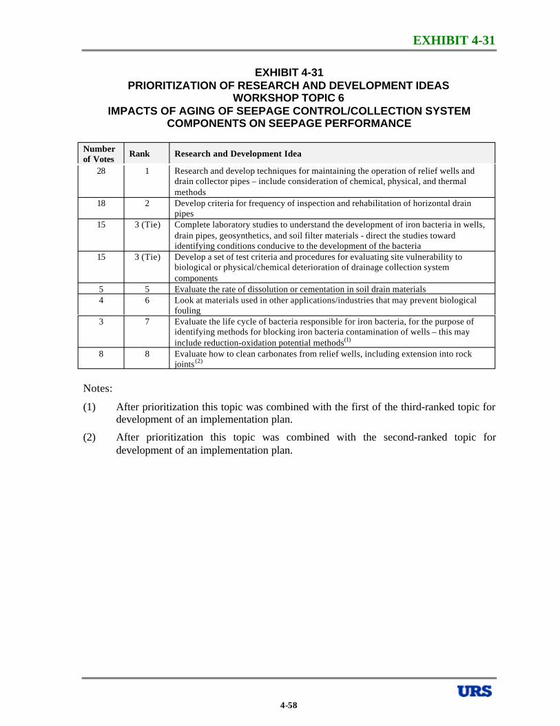
EXHIBIT 4-31
EXHIBIT 4-31 PRIORITIZATION OF RESEARCH AND DEVELOPMENT IDEAS
WORKSHOP TOPIC 6 IMPACTS OF AGING OF SEEPAGE CONTROL/COLLECTION SYSTEM
COMPONENTS ON SEEPAGE PERFORMANCE
Number of Votes
Rank Research and Development Idea
28 1 Research and develop techniques for maintaining the operation of relief wells and drain collector pipes – include consideration of chemical, physical, and thermal methods
18 2 Develop criteria for frequency of inspection and rehabilitation of horizontal drain pipes
15 3 (Tie) Complete laboratory studies to understand the development of iron bacteria in wells, drain pipes, geosynthetics, and soil filter materials - direct the studies toward identifying conditions conducive to the development of the bacteria
15 3 (Tie) Develop a set of test criteria and procedures for evaluating site vulnerability to biological or physical/chemical deterioration of drainage collection system components
5 5 Evaluate the rate of dissolution or cementation in soil drain materials 4 6 Look at materials used in other applications/industries that may prevent biological
fouling 3 7 Evaluate the life cycle of bacteria responsible for iron bacteria, for the purpose of
identifying methods for blocking iron bacteria contamination of wells – this may include reduction-oxidation potential methods(1)
8 8 Evaluate how to clean carbonates from relief wells, including extension into rock joints(2)
Notes:
(1) After prioritization this topic was combined with the first of the third-ranked topic for development of an implementation plan.
(2) After prioritization this topic was combined with the second-ranked topic for development of an implementation plan.
4-58
EXHIBIT 4-32
EXHIBIT 4-32 RESEARCH AND DEVELOPMENT IMPLEMENTATION PLAN
R&D TOPIC 6A RESEARCH AND DEVELOP TECHNIQUES FOR REMEDIATION AND
PREVENTION OF CONTAMINATION OF WELLS, DRAINS, AND INSTRUMENTATION
1. Description
A. Why is this a priority research/development item?
1) Contamination/deterioration of drains and wells leads to reduced effectiveness of seepage collection/control systems.
2) Contamination/deterioration of instruments (piezometers) leads to lengthened response times and possibly erroneous performance data.
B. What is the expected outcome?
1) Recommended designs to reduce the likelihood of contamination.
2) Recommended procedures/methods to rehabilitate contaminated drains, wells, and instruments.
2. Project Tasks and Needs
A. What tasks are to be done?
B. How is the problem to be solved?
1) Collect and evaluate case history information for dams with contamination problems and dams without contamination problems.
2) Collect and evaluate case history information for successful and unsuccessful attempts to rehabilitate contaminated drains, wells, and instruments.
3) Plan and conduct laboratory and field research to investigate and resolve questions identified in the case study reviews.
4) Develop and publish a report with recommended guidelines.
3. Project Lead and Contact
A. Who is working in this area?
1) USACE, NRCS, USBR, water well industry.
B. Who might be able to lead the project?
C. Who are good candidates to complete the work?
1) USACE, NRCS, USBR, a university (graduate research).
4-59

EXHIBIT 4-33
EXHIBIT 4-33 RESEARCH AND DEVELOPMENT IMPLEMENTATION PLAN
R&D TOPIC 6B CRITERIA FOR FREQUENCY OF INSPECTIONS AND REHABILITATION OF
HORIZONTAL DRAINS, INCLUDING REMOVAL OF CARBONATES 1. Description
A. Why is this a priority research/development item?
1) No existing criteria are available.
2) There is evidence of drain clogging in existing dams.
3) In many cases, drain systems have been neglected by owners.
B. What is the expected outcome?
1) Recommendations for inspection techniques and rehabilitation procedures.
2) Recommendations for instrumentation to detect clogging.
3) Improve facilities design, inspection, maintenance, and rehabilitation.
2. Project Tasks and Needs
A. What tasks are to be done?
1) Literature survey.
2) Canvas for case histories.
3) Review of available technologies in sewer and relief well inspection and maintenance.
4) Identification of potential problems with maintenance methods.
B. How is the problem to be solved?
1) Guidance document.
3. Project Lead and Contact
A. Who is working in this area?
1) Sewer industry contractors.
2) Industrial pipe cleaners – oil-chemical industries.
3) Manufacturing plants.
4) Water well contractors.
B. Who might be able to lead the project?
1) USBR.
2) USACE.
C. Who are good candidates to complete the work?
1) Industrial pipe cleaners.
4-60
EXHIBIT 4-34
EXHIBIT 4-34 RESEARCH AND DEVELOPMENT IMPLEMENTATION PLAN
R&D TOPIC 6C RESEARCH METHODS TO CONTROL AND/OR REMOVE IRON BACTERIA
DEPOSITS FROM WELLS AND DRAIN SYSTEMS 1. Description
A. Why is this a priority research/development item?
1) It is a major cause of degradation of wells and drain systems.
2) It is a large consumer of maintenance and repair funds.
B. What is the expected outcome?
1) Techniques to control the iron bacteria life cycle level.
2) Refinement/optimization of current techniques.
3) Automated treatment and systems (e.g., sacrificial anode effect).
2. Project Tasks and Needs
A. Wha t tasks are to be done?
1) Research life cycle of iron bacteria (biologist).
2) Evaluate existing technology:
a) Water well industry.
b) Water supply engineers.
c) Chemists.
B. How is the problem to be solved?
1) Fund Ph.D. student for life cycle research.
2) Fund field tests (practical application techniques).
3. Project Lead and Contact
A. Who is working in this area?
1) American Waterworks Association.
2) USBR.
3) USACE.
B. Who might be able to lead the project?
C. Who are good candidates to complete the work?
1) Multidiscipline Advisory Committee.
4-61
EXHIBIT 4-35
EXHIBIT 4-35 RESEARCH AND DEVELOPMENT IMPLEMENTATION PLAN
R&D TOPIC 6D DEVELOP TEST CRITERIA AND PROCEDURES FOR EVALUATING SITE
VULNERABILITY TO PHYSICAL/CHEMICAL/BIOLOGICAL DETERIORATION OF SEEPAGE COLLECTION AND CONTROL SYSTEMS
1. Description
A. Why is this a priority research/development item?
1) It is a problem.
2) Information is not consolidated or used in dam engineering.
3) Could help avoid problems or better design for them.
B. What is the expected outcome?
1) Recommended investigation, sampling, and testing procedures.
2) Guide for interpretation of results.
2. Project Tasks and Needs
A. What tasks are to be done?
B. How is the problem to be solved?
1) Information research.
2) Consulting with experts outside of our field (dam design and construction).
3) Evaluate and compile information.
4) Field validate procedures.
5) Produce guidelines.
3. Project Lead and Contact
A. Who is working in this area?
1) Other industries (chemical, coatings, concrete, well drilling).
2) USBR.
3) USACE.
B. Who might be able to lead the project?
C. Who are good candidates to complete the work?
1) USBR.
2) USACE.
4-62
5.0 OVERALL PRIORITIZATION
5.0 OVERALL PRIORITIZATION OF RESEARCH AND DEVELOPMENT IDEAS
As discussed in Section 4, the prioritization of the research and development ideas for each of the six topics considered in the workshop resulted in the identification of 29 leading ideas (4 or 5 ideas for each topic), for which preliminary implementation plans were developed. Before the overall prioritization of the leading research and development ideas was completed, the workshop participants agreed to combine some of the ideas, reducing the total number of research and development ideas to be prioritized to 26. Specifically, R&D Topic 1A (Compilation of Case Histories of Seepage Incidents Related to Penetrations Through Embankment Dams) was combined with R&D Topic 3E (Expand the Database of Information on Seepage/Piping Failures/Incidents for Dams <15 meters in Height), R&D Topic 1D (Guidelines for Inspecting, Monitoring, and Detecting Seepage Along Penetrations Through Embankment Dams) was combined with R&D Topic 3B (Develop Guidance for Dam Surveillance Plans Relative to Seepage), and R&D Topic 2C (Evaluate Mechanism Of Piping And Failure In Glacial, Alluvial, And Fluvial Environments – Including Consideration Of Internal Instability) was combined with R&D Topic 2E (Threshold Gradients for Initiating Piping in Cohesive Soils).
The resulting 26 R&D topics were then prioritized: 1) in a session at the end of the workshop and 2) by input provided by the workshop participants after they returned home from the workshop. The prioritization of those 26 leading research and development ideas is discussed in this section.
In accordance with the guidance provided by the ASDSO Seepage Advisory Committee, the research and development ideas were prioritized considering the following three criteria:
1. Potential benefit.
2. Probability of success.
3. Cost.
The prioritization was completed in three different ways, as discussed below, and as summarized in Exhibits 5-1 through 5-7.
PRIORITIZATION AT THE END OF THE WORKSHOP
In a session at the end of the workshop, the participants were asked to prioritize the 26 leading ideas considering the balance of the three criteria noted above. The research and development ideas were posted on flip chart paper displayed on the walls of the room, and each participant was given 10 “stick-on” dots with which to cast their “votes.” The participants could cast as many votes as they wanted for any particular research and development idea, provided that they did not cast more than 10 votes in total. The results of this process are summarized on Exhibit 5-1, where the ideas are listed in rank order based on the numbers of votes received. As seen in Exhibit 5-1, the top 11 ideas (including a tie for the 10th position) according to this process are:
1. Enhance Academic Programs and Professional Development and Training Programs Related to Seepage Issues in Dam Design and Rehabilitation – “Certification” of Dam Designers, Dam Construction Inspectors, and Dam Operators
5-1
5.0 OVERALL PRIORITIZATION2. Evaluate Mechanism Of Piping And Failure In Glacial, Alluvial, And Fluvial
Environments – Including Consideration Of Internal Instability, and Including Consideration of Threshold Gradients for Initiating Piping in Cohesive Soils
3. Expand the Database of Information on Seepage/Piping Failures/Incidents for Dams <15 meters in Height, and Compile Case Histories of Seepage Incidents Related to Penetrations through Embankment Dams
3. Technology Transfer of Geophysical Techniques for Seepage Monitoring
5. Develop Guidelines for Design of Filter Diaphragms Associated with Conduits through Embankment Dams
6. Evaluate the Performance of In-Place Geotextiles in Seepage Control Applications
6. Research Methods to Control and/or Remove Iron Bacteria Deposits From Wells and Drain Systems
8. Develop State-of-the-Practice for Configurations, Dimensions, and Construction Methods for Filters and Drains
9. Assess Technology to Detect Voids and Concentrated Seepage around Penetrations through Embankment Dams
10. Develop Design Criteria for Drainage Pipe Openings and Surrounding Material to Prevent Plugging
10. Testing of Fabric Clogging Under Steady State Flow Properly Simulating Conditions in Dam Applications
Note that this list includes ideas tied at ranks 3, 6, and 10.
PRIORITIZATION AFTER THE WORKSHOP
The participants were asked to repeat this overall prioritization process again, after they returned home from the workshop. The participants were sent a table of the 26 leading ideas along with the preliminary implementation plans developed at the workshop, and there were asked to again cast 10 votes considering the balance of the three identified criteria, using the same rules used at the workshop. Twenty-nine individuals provided input to this process, and the results are summarized in Exhibit 5-2. The top 12 ideas (including a three-way tie for 10th
position) according to this overall rating process are:
1. Expand the Database of Information on Seepage/Piping Failures/Incidents for Dams <15 meters in Height, and Compile Case Histories of Seepage Incidents Related to Penetrations Through Embankment Dams
2. Enhance Academic Programs and Professional Development and Training Programs Related to Seepage Issues in Dam Design and Rehabilitation – “Certification” of Dam Designers, Dam Construction Inspectors, and Dam Operators
3. Develop State-of-the-Practice for Configurations, Dimensions, and Construction Methods for Filters and Drains
4. Evaluate Mechanism of Piping and Failure in Glacial, Alluvial, and Fluvial Environments – Including Consideration of Internal Instability, and Including Consideration of Threshold Gradients for Initiating Piping in Cohesive Soils
5-2
5.0 OVERALL PRIORITIZATION5. Develop Guidance for Dam Surveillance Plans Relative to Seepage, Including
Monitoring, and Detecting Seepage Along Penetrations Through Embankment Dams
6. Assess Technology to Detect Voids and Concentrated Seepage around Penetrations through Embankment Dams
7. Technology Transfer of Geophysical Techniques for Seepage Monitoring
7. Compilation of Practices, Applications, Experiences, Economics, and Advantages/Disadvantages of Using Geotextiles in Dam Applications
7. Develop Design Criteria for Drainage Pipe Openings and Surrounding Material to Prevent Plugging
10. Develop Guidelines for Design of Filter Diaphragms Associated with Conduits through Embankment Dams
10. Classification of Conditions Conducive to Hydraulic Fracturing and Cracking
10. Testing of Fabric Clogging Under Steady State Flow Properly Simulating Conditions in Dam Applications
Note that this list includes ideas tied at ranks 7 and 10.
In addition to the overall ratings summarized in Exhibit 5-2, the participants were asked to score the 26 ideas separately for each of the three criteria: potential benefit, probability of success, and cost. For each criterion, the participants were asked to score each idea from 1 to 4, with 1 being most favorable and 4 being least favorable. Again, 29 participants provided input to this process. The average scores for the 26 ideas for the three criteria are presented separately in Exhibits 5-3, 5-4, and 5-5. In each of those exhibits, the ideas are listed in rank order according the average scores for the individual criterion. In Exhibit 5.6, the individual scores for the three different criteria are combined by computing an arithmetic average of the three individual scores, giving equal weight to each of the criterion. The top 10 topics resulting from this process are:
1. Develop Guidelines for Design of Filter Diaphragms Associated with Conduits through Embankment Dams
2. Develop State-of-the-Practice for Configurations, Dimensions, and Construction Methods for Filters and Drains
3. Develop Guidance for Dam Surveillance Plans Relative to Seepage, Including Monitoring, and Detecting Seepage along Penetrations through Embankment Dams
4. Development and Deployment of Guidelines for Slip-linings of Outlet Works Conduits
5. Expand the Database of Information on Seepage/Piping Failures/Incidents for Dams <15 meters in Height, and Compile Case Histories of Seepage Incidents Related to Penetrations through Embankment Dams
6. Compilation of Practices, Applications, Experiences, Economics, and Advantages/Disadvantages of Using Geotextiles in Dam Applications
7. Enhance Academic Programs and Professional Development and Training Programs Related to Seepage Issues in Dam Design and Rehabilitation – “Certification” of Dam Designers, Dam Construction Inspectors, and Dam Operators
8. Develop Design Criteria for Drainage Pipe Openings and Surrounding Material to Prevent Plugging
5-3
5.0 OVERALL PRIORITIZATION9. Review of Performance of Seepage Remediation Measures: a) Upstream Cutoff only, b)
Upstream Cutoff with Downstream Collection, and c) Downstream Collection Only
9. Classification of Conditions Conducive to Hydraulic Fracturing and Cracking
Note that this list includes ideas tied at rank 9.
The participants were also asked to provide estimates of the cost of implementing each of the research and development ideas, if they felt qualified to do so. Unfortunately, only 11 participants felt qualified to provide cost information and the estimates provided varied widely. Consequently, the results are not particularly helpful, but they are provided in this report for completeness.
The participants were asked to provide “low,” “best estimate,” and “high” values for the cost of implementing each of the 26 research and development ideas. Eleven participants provided “best estimate” values, and nine participants provided “low” and “high” values. The “best estimate” values are summarized in Exhibit 5-7, which includes low, high, average, and median “best estimates,” and a standard deviation of the “best estimates” for each R&D topic. In all cases the standard deviations are greater than the average values, illustrating the wide range of the estimates. Summaries of the “low” and “high” values are provided in Attachment 10 of this report, and they also show wide variations. The individual “low,” “best estimate,” and “high” values from the participants are also presented in Attachment 10. A panel experienced with the cost of scientific and engineering research may be able to refine the estimated cost data provided by the participants to develop more constrained estimates of implementation costs.
COMPARISON AND COMBINATION OF RESULTS FROM DIFFERENT RANKING METHODS
In Exhibit 5-8, the rankings for the 26 research and development ideas from all three methods are compared and combined. The overall rankings resulting from the three different processes are averaged, and the ideas are listed in order of average ranking. The resulting top 10 ideas are:
1. Expand the Database of Information on Seepage/Piping Failures/Incidents for Dams <15 meters in Height, and Compile Case Histories of Seepage Incidents Related to Penetrations through Embankment Dams
2. Enhance Academic Programs and Professional and Training Development Programs Related to Seepage Issues in Dam Design and Rehabilitation – “Certification” of Dam Designers, Dam Construction Inspectors, and Dam Operators
3. Develop State-of-the-Practice for Configurations, Dimensions, and Construction Methods for Filters and Drains
4. Develop Guidelines for Design of Filter Diaphragms Associated with Conduits through Embankment Dams
5. Develop Guidance for Dam Surveillance Plans Relative to Seepage, Including Monitoring, and Detecting Seepage Along Penetrations through Embankment Dams
6. Technology Transfer of Geophysical Techniques for Seepage Monitoring
7. Evaluate Mechanism of Piping and Failure in Glacial, Alluvial, and Fluvial Environments – Including Consideration of Internal Instability, and Including Consideration of Threshold Gradients for Initiating Piping in Cohesive Soils
5-4
5.0 OVERALL PRIORITIZATION8. Develop Design Criteria for Drainage Pipe Openings and Surrounding Material to
Prevent Plugging
9. Compilation of Practices, Applications, Experiences, Economics, and Advantages/Disadvantages of Using Geotextiles in Dam Applications
10. Assess Technology to Detect Voids and Concentrated Seepage around Penetrations through Embankment Dams
OVERALL PRIORITIZATION OF RESEARCH AND DEVELOPMENT IDEAS
In reviewing the results of the overall rankings using the three different methods (Exhibits 51, 5-2, and 5-6), it is seen that the priority order of the ideas varies somewhat among the three methods. However, by analyzing the information summarized in Exhibit 5-8, the authors believe that priorities among the ideas become clear. To assist in this effort, all of the individual top 10 rankings (for the three separate methods) have been indicated by shaded boxes in Exhibit 5-8.
Considering the combination of the number of rankings in the top 10 and the average rankings (averages of the individual rankings from all three methods), it is the authors’ opinion that the following four topics are clearly the highest priority of the research and development ideas considered:
1. Expand the Database of Information on Seepage/Piping Failures/Incidents for Dams <15 meters in Height, and Compile Case Histories of Seepage Incidents Related to Penetrations Through Embankment Dams (R&D Topics 3E & 1A)
2. Enhancement Academic Programs and Professional Development and Training Programs Related to Seepage Issues in Dam Design and Rehabilitation – “Certification” of Dam Designers, Dam Construction Inspectors, and Dam Operators (R&D Topic 3A)
3. Develop State-of-the-Practice for Configurations, Dimensions, and Construction Methods for Filters and Drains (R&D Topic 2B)
4. Develop Guidelines for Design of Filter Diaphragms Associated With Conduits Through Embankment Dams (R&D Topic 1C)
All four of these ideas were ranked in the top 10 by all three methods used and they ranked 1 through 4 in the average ranking (average of individual rankings in the three methods).
In the authors’ opinion, the next six research and development ideas listed in Exhibit 5-8 should also be considered high priority research and development ideas, but not as high as the top four topics. Those six topics are:
1. Develop Design Criteria for Drainage Pipe Openings and Surrounding Material to Prevent Plugging (R&D Topic 5D)
2. Develop Guidance for Dam Surveillance Plans Relative to Seepage, Including Monitoring, and Detecting Seepage Along Penetrations Through Embankment Dams (R&D Topics 3B & 1D)
3. Technology Transfer of Geophysical Techniques for Seepage Monitoring (R&D Topic 4A)
4. Evaluate Mechanism of Piping and Failure in Glacial, Alluvial, and Fluvial Environments – Including Consideration of Internal Instability, and Including Consideration of Threshold Gradients for Initiating Piping in Cohesive Soils (R&D Topics 2C& 2E)
5-5
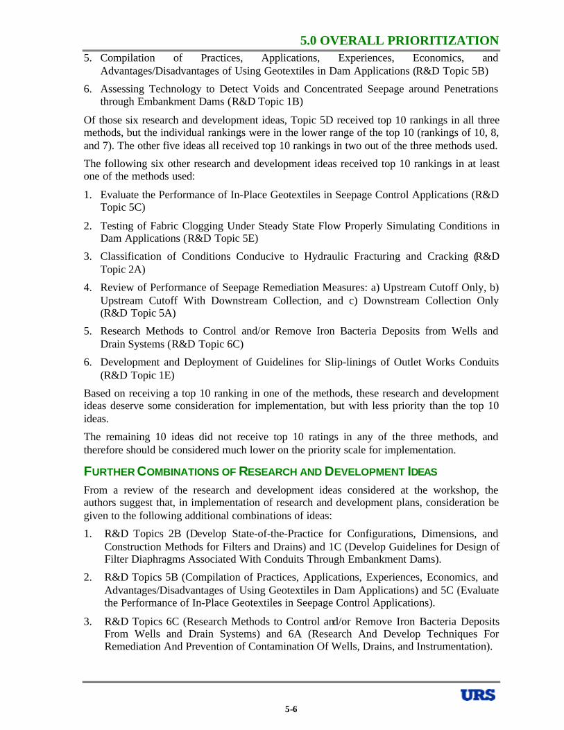
5.0 OVERALL PRIORITIZATION5. Compilation of Practices, Applications, Experiences, Economics, and
Advantages/Disadvantages of Using Geotextiles in Dam Applications (R&D Topic 5B)
6. Assessing Technology to Detect Voids and Concentrated Seepage around Penetrations through Embankment Dams (R&D Topic 1B)
Of those six research and development ideas, Topic 5D received top 10 rankings in all three methods, but the individual rankings were in the lower range of the top 10 (rankings of 10, 8, and 7). The other five ideas all received top 10 rankings in two out of the three methods used.
The following six other research and development ideas received top 10 rankings in at least one of the methods used:
1. Evaluate the Performance of In-Place Geotextiles in Seepage Control Applications (R&D Topic 5C)
2. Testing of Fabric Clogging Under Steady State Flow Properly Simulating Conditions in Dam Applications (R&D Topic 5E)
3. Classification of Conditions Conducive to Hydraulic Fracturing and Cracking (R&D Topic 2A)
4. Review of Performance of Seepage Remediation Measures: a) Upstream Cutoff Only, b) Upstream Cutoff With Downstream Collection, and c) Downstream Collection Only (R&D Topic 5A)
5. Research Methods to Control and/or Remove Iron Bacteria Deposits from Wells and Drain Systems (R&D Topic 6C)
6. Development and Deployment of Guidelines for Slip-linings of Outlet Works Conduits (R&D Topic 1E)
Based on receiving a top 10 ranking in one of the methods, these research and development ideas deserve some consideration for implementation, but with less priority than the top 10 ideas.
The remaining 10 ideas did not receive top 10 ratings in any of the three methods, and therefore should be considered much lower on the priority scale for implementation.
FURTHER COMBINATIONS OF RESEARCH AND DEVELOPMENT IDEAS
From a review of the research and development ideas considered at the workshop, the authors suggest that, in implementation of research and development plans, consideration be given to the following additional combinations of ideas:
1. R&D Topics 2B (Develop State-of-the-Practice for Configurations, Dimensions, and Construction Methods for Filters and Drains) and 1C (Develop Guidelines for Design of Filter Diaphragms Associated With Conduits Through Embankment Dams).
2. R&D Topics 5B (Compilation of Practices, Applications, Experiences, Economics, and Advantages/Disadvantages of Using Geotextiles in Dam Applications) and 5C (Evaluate the Performance of In-Place Geotextiles in Seepage Control Applications).
3. R&D Topics 6C (Research Methods to Control and/or Remove Iron Bacteria Deposits From Wells and Drain Systems) and 6A (Research And Develop Techniques For Remediation And Prevention of Contamination Of Wells, Drains, and Instrumentation).
5-6
5.0 OVERALL PRIORITIZATION4. R&D Topics 3B & 1D (Develop Guidance for Dam Surveillance Plans Relative to
Seepage, Including Monitoring, and Detecting Seepage Along Penetrations Through Embankment Dams) and 1B (Assess Technology to Detect Voids and Concentrated Seepage around Penetrations through Embankment Dams).
OBSERVATIONS CONCERNING RESEARCH AND DEVELOPMENT IDEAS
In reviewing the leading research and development ideas as discussed above, it is interesting to note that very few of the ideas involve basic laboratory or field research. In fact, only R&D Topics 2E, 5D, 1B, 5E, 2A, and 6C include such basic research, and none of the top four topics listed above include basic research. Rather, most of the topics involve collecting or compiling available information and developing guidelines for dissemination to practitioners. In the authors’ opinion, this reflects a sense among the workshop participants that the topic of seepage through embankment dams is relatively mature, and that most seepage problems are the result of misuse or misunderstanding of available information or lack of knowledge of available information by some members of the engineering community. It also seems to reflect a feeling that the information on seepage through embankment dams is too dispersed for the profession to make the best use of lessons-learned from past performance, and that compilation of information into more readily available sources would be beneficial.
5-7
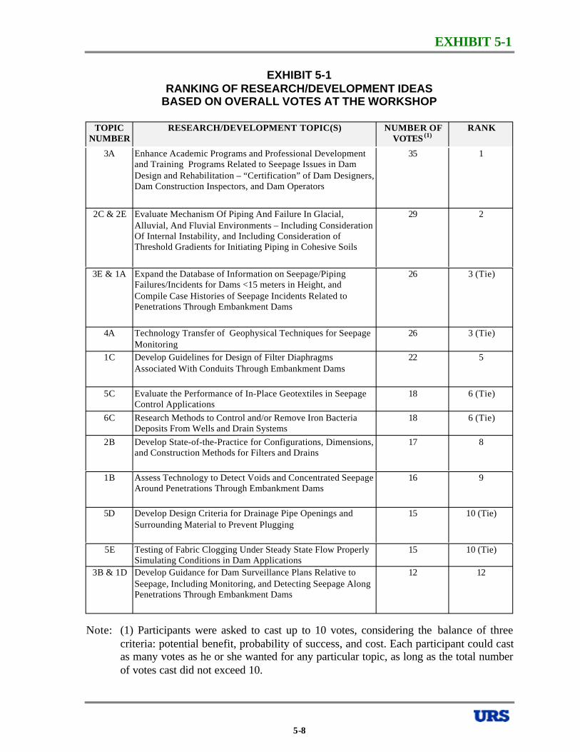
EXHIBIT 5-1
EXHIBIT 5-1 RANKING OF RESEARCH/DEVELOPMENT IDEAS
BASED ON OVERALL VOTES AT THE WORKSHOP
TOPIC NUMBER
RESEARCH/DEVELOPMENT TOPIC(S) NUMBER OF VOTES (1)
RANK
3A Enhance Academic Programs and Professional Development 35 and Training Programs Related to Seepage Issues in Dam Design and Rehabilitation – “Certification” of Dam Designers, Dam Construction Inspectors, and Dam Operators
2C & 2E Evaluate Mechanism Of Piping And Failure In Glacial, 29 Alluvial, And Fluvial Environments – Including Consideration Of Internal Instability, and Including Consideration of Threshold Gradients for Initiating Piping in Cohesive Soils
3E & 1A Expand the Database of Information on Seepage/Piping 26 Failures/Incidents for Dams <15 meters in Height, and Compile Case Histories of Seepage Incidents Related to Penetrations Through Embankment Dams
4A Technology Transfer of Geophysical Techniques for Seepage 26 Monitoring
1C Develop Guidelines for Design of Filter Diaphragms 22 Associated With Conduits Through Embankment Dams
5C Evaluate the Performance of In-Place Geotextiles in Seepage 18 Control Applications
6C Research Methods to Control and/or Remove Iron Bacteria 18 Deposits From Wells and Drain Systems
2B Develop State-of-the-Practice for Configurations, Dimensions, 17 and Construction Methods for Filters and Drains
1B Assess Technology to Detect Voids and Concentrated Seepage 16 Around Penetrations Through Embankment Dams
5D Develop Design Criteria for Drainage Pipe Openings and 15 Surrounding Material to Prevent Plugging
5E Testing of Fabric Clogging Under Steady State Flow Properly 15 Simulating Conditions in Dam Applications
3B & 1D Develop Guidance for Dam Surveillance Plans Relative to 12 Seepage, Including Monitoring, and Detecting Seepage Along Penetrations Through Embankment Dams
1
2
3 (Tie)
3 (Tie)
5
6 (Tie)
6 (Tie)
8
9
10 (Tie)
10 (Tie)
12
Note: (1) Participants were asked to cast up to 10 votes, considering the balance of three criteria: potential benefit, probability of success, and cost. Each participant could cast as many votes as he or she wanted for any particular topic, as long as the total number of votes cast did not exceed 10.
5-8

EXHIBIT 5-1
EXHIBIT 5-1 RANKING OF RESEARCH/DEVELOPMENT IDEAS
BASED ON OVERALL VOTES AT THE WORKSHOP -CONTINUED
TOPIC NUMBER
RESEARCH/DEVELOPMENT TOPIC(S) NUMBER OF VOTES (1)
RANK
4B Test Capabilities of Different Geophysical Methods on a Test 11 13 Embankment
5B Compilation of Practices, Applications, Experiences, 9 14 Economics, and Advantages/Disadvantages of Using Geotextiles in Dam Applications
5A Review of Performance of Seepage Remediation Measures: a) 6 15 Upstream Cutoff Only, b) Upstream Cutoff With Downstream Collection, and c) Downstream Collection Only
6D Develop Test Criteria and Procedures for Evaluating Site 5 16 Vulnerability to Physical/Chemical/Biological Deterioration of Seepage Collection and Control Systems
4C Cross-Discipline Technology Transfer for Investigative 4 17 (Tie) Techniques in Dams
4E Assess Photo-Monitoring Techniques for Seepage (Infrared 4 17 (Tie) Imaging, Photo Interpretation, etc.)
2A Classification of Conditions Conducive to Hydraulic 3 19 (Tie) Fracturing and Cracking
6B Criteria for Frequency of Inspections and Rehabilitation of 3 19 (Tie) Horizontal Drains, Including Removal of Carbonates
2D Evaluation of Mechanical/Geochemical Degradation of 2 21 (Tie) Properties of Filter Materials, Including Cementation and the Ability to Sustain a Crack
3C Improve Failure Time Estimates for Seepage-Related Failure 2 21 (Tie) Modes for Existing Dams
6A Research And Develop Techniques For Remediation And 2 21 (Tie) Prevention Of Contamination Of Wells, Drains, And Instrumentation
1E Development and Deployment of Guidelines for Slip-linings 1 24 of Outlet Works Conduits
3D Identify Factors for Failure for a) “First Filling” (Including 0 25 (Tie) Normally Dry Dams/Detention Dams, Maximum Pool, etc.) and b) Long Term, for Each Seepage-Related Failure Mode
4D Do/Can Instruments or Instrument Installations Cause Damage 0 25 (Tie) in Embankment Dams
Note: (1) Participants were asked to cast up to 10 votes, considering the balance of three criteria: potential benefit, probability of success, and cost. Each participant could cast as many votes as he or she wanted for any particular topic, as long as the total number of votes cast did not exceed 10.
5-9
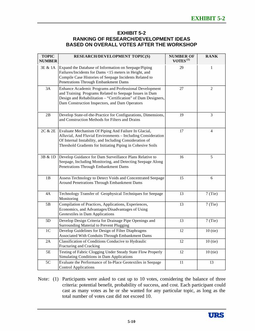
EXHIBIT 5-2
EXHIBIT 5-2 RANKING OF RESEARCH/DEVELOPMENT IDEAS
BASED ON OVERALL VOTES AFTER THE WORKSHOP
TOPIC NUMBER
RESEARCH/DEVELOPMENT TOPIC(S) NUMBER OF VOTES (1)
RANK
3E & 1A Expand the Database of Information on Seepage/Piping 29 1 Failures/Incidents for Dams <15 meters in Height, and Compile Case Histories of Seepage Incidents Related to Penetrations Through Embankment Dams
3A Enhance Academic Programs and Professional Development 27 2 and Training Programs Related to Seepage Issues in Dam Design and Rehabilitation – “Certification” of Dam Designers, Dam Construction Inspectors, and Dam Operators
2B Develop State-of-the-Practice for Configurations, Dimensions, 19 3 and Construction Methods for Filters and Drains
2C & 2E Evaluate Mechanism Of Piping And Failure In Glacial, 17 4 Alluvial, And Fluvial Environments – Including Consideration Of Internal Instability, and Including Consideration of Threshold Gradients for Initiating Piping in Cohesive Soils
3B & 1D Develop Guidance for Dam Surveillance Plans Relative to 16 5 Seepage, Including Monitoring, and Detecting Seepage Along Penetrations Through Embankment Dams
1B Assess Technology to Detect Voids and Concentrated Seepage 15 6 Around Penetrations Through Embankment Dams
4A Technology Transfer of Geophysical Techniques for Seepage 13 7 (Tie) Monitoring
5B Compilation of Practices, Applications, Experiences, 13 7 (Tie) Economics, and Advantages/Disadvantages of Using Geotextiles in Dam Applications
5D Develop Design Criteria for Drainage Pipe Openings and 13 7 (Tie) Surrounding Material to Prevent Plugging
1C Develop Guidelines for Design of Filter Diaphragms 12 10 (tie) Associated With Conduits Through Embankment Dams
2A Classification of Conditions Conducive to Hydraulic 12 10 (tie) Fracturing and Cracking
5E Testing of Fabric Clogging Under Steady State Flow Properly 12 10 (tie) Simulating Conditions in Dam Applications
5C Evaluate the Performance of In-Place Geotextiles in Seepage 11 13 Control Applications
Note: (1) Participants were asked to cast up to 10 votes, considering the balance of three criteria: potential benefit, probability of success, and cost. Each participant could cast as many votes as he or she wanted for any particular topic, as long as the total number of votes cast did not exceed 10.
5-10
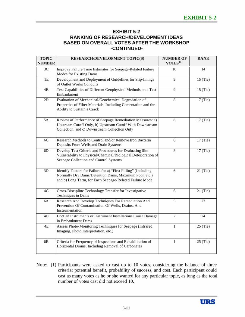
EXHIBIT 5-2
EXHIBIT 5-2 RANKING OF RESEARCH/DEVELOPMENT IDEAS
BASED ON OVERALL VOTES AFTER THE WORKSHOP -CONTINUED
TOPIC NUMBER
RESEARCH/DEVELOPMENT TOPIC(S) NUMBER OF VOTES (1)
RANK
3C Improve Failure Time Estimates for Seepage-Related Failure 10 14 Modes for Existing Dams
1E Development and Deployment of Guidelines for Slip-linings 9 15 (Tie) of Outlet Works Conduits
4B Test Capabilities of Different Geophysical Methods on a Test 9 15 (Tie) Embankment
2D Evaluation of Mechanical/Geochemical Degradation of 8 17 (Tie) Properties of Filter Materials, Including Cementation and the Ability to Sustain a Crack
5A Review of Performance of Seepage Remediation Measures: a) 8 17 (Tie) Upstream Cutoff Only, b) Upstream Cutoff With Downstream Collection, and c) Downstream Collection Only
6C Research Methods to Control and/or Remove Iron Bacteria 8 17 (Tie) Deposits From Wells and Drain Systems
6D Develop Test Criteria and Procedures for Evaluating Site 8 17 (Tie) Vulnerability to Physical/Chemical/Biological Deterioration of Seepage Collection and Control Systems
3D Identify Factors for Failure for a) “First Filling” (Including 6 21 (Tie) Normally Dry Dams/Detention Dams, Maximum Pool, etc.) and b) Long Term, for Each Seepage-Related Failure Mode
4C Cross-Discipline Technology Transfer for Investigative 6 21 (Tie) Techniques in Dams
6A Research And Develop Techniques For Remediation And 5 23 Prevention Of Contamination Of Wells, Drains, And Instrumentation
4D Do/Can Instruments or Instrument Installations Cause Damage 2 24 in Embankment Dams
4E Assess Photo-Monitoring Techniques for Seepage (Infrared 1 25 (Tie) Imaging, Photo Interpretation, etc.)
6B Criteria for Frequency of Inspections and Rehabilitation of 1 25 (Tie) Horizontal Drains, Including Removal of Carbonates
Note: (1) Participants were asked to cast up to 10 votes, considering the balance of three criteria: potential benefit, probability of success, and cost. Each participant could cast as many votes as he or she wanted for any particular topic, as long as the total number of votes cast did not exceed 10.
5-11
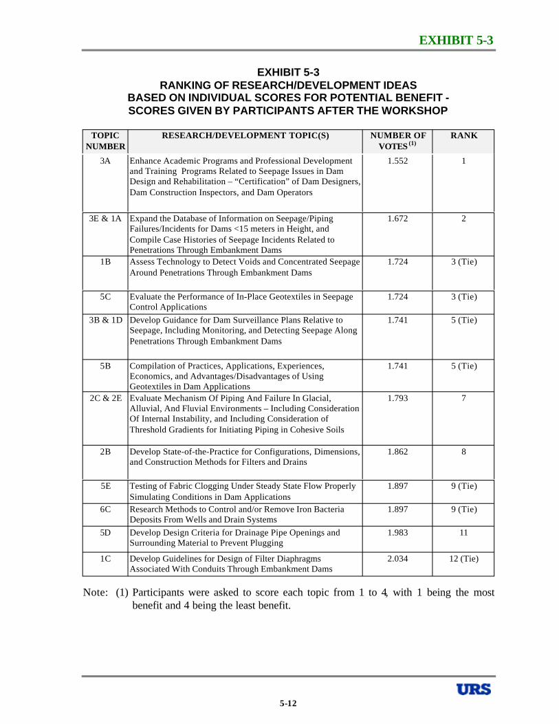
EXHIBIT 5-3
EXHIBIT 5-3 RANKING OF RESEARCH/DEVELOPMENT IDEAS
BASED ON INDIVIDUAL SCORES FOR POTENTIAL BENEFIT SCORES GIVEN BY PARTICIPANTS AFTER THE WORKSHOP
TOPIC NUMBER
RESEARCH/DEVELOPMENT TOPIC(S) NUMBER OF VOTES (1)
RANK
3A Enhance Academic Programs and Professional Development and Training Programs Related to Seepage Issues in Dam Design and Rehabilitation – “Certification” of Dam Designers, Dam Construction Inspectors, and Dam Operators
3E & 1A Expand the Database of Information on Seepage/Piping Failures/Incidents for Dams <15 meters in Height, and Compile Case Histories of Seepage Incidents Related to Penetrations Through Embankment Dams
1B Assess Technology to Detect Voids and Concentrated Seepage Around Penetrations Through Embankment Dams
5C Evaluate the Performance of In-Place Geotextiles in Seepage Control Applications
3B & 1D Develop Guidance for Dam Surveillance Plans Relative to Seepage, Including Monitoring, and Detecting Seepage Along Penetrations Through Embankment Dams
5B Compilation of Practices, Applications, Experiences, Economics, and Advantages/Disadvantages of Using Geotextiles in Dam Applications
2C & 2E Evaluate Mechanism Of Piping And Failure In Glacial, Alluvial, And Fluvial Environments – Including Consideration Of Internal Instability, and Including Consideration of Threshold Gradients for Initiating Piping in Cohesive Soils
2B Develop State-of-the-Practice for Configurations, Dimensions, and Construction Methods for Filters and Drains
5E Testing of Fabric Clogging Under Steady State Flow Properly Simulating Conditions in Dam Applications
6C Research Methods to Control and/or Remove Iron Bacteria Deposits From Wells and Drain Systems
5D Develop Design Criteria for Drainage Pipe Openings and Surrounding Material to Prevent Plugging
1C Develop Guidelines for Design of Filter Diaphragms Associated With Conduits Through Embankment Dams
1.552 1
1.672 2
1.724 3 (Tie)
1.724 3 (Tie)
1.741 5 (Tie)
1.741 5 (Tie)
1.793 7
1.862 8
1.897 9 (Tie)
1.897 9 (Tie)
1.983 11
2.034 12 (Tie)
Note: (1) Participants were asked to score each topic from 1 to 4, with 1 being the most benefit and 4 being the least benefit.
5-12
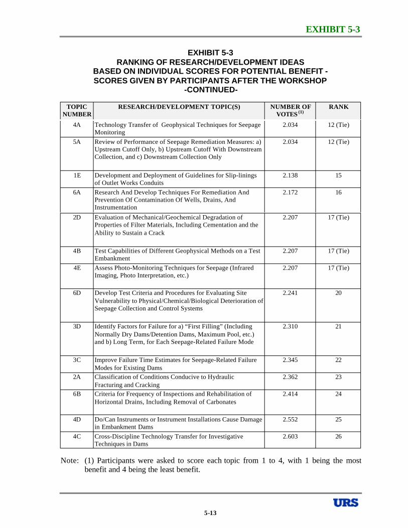
EXHIBIT 5-3
EXHIBIT 5-3 RANKING OF RESEARCH/DEVELOPMENT IDEAS
BASED ON INDIVIDUAL SCORES FOR POTENTIAL BENEFIT SCORES GIVEN BY PARTICIPANTS AFTER THE WORKSHOP
-CONTINUED
TOPIC NUMBER
RESEARCH/DEVELOPMENT TOPIC(S) NUMBER OF VOTES (1)
RANK
4A Technology Transfer of Geophysical Techniques for Seepage 2.034 12 (Tie) Monitoring
5A Review of Performance of Seepage Remediation Measures: a) 2.034 12 (Tie) Upstream Cutoff Only, b) Upstream Cutoff With Downstream Collection, and c) Downstream Collection Only
1E Development and Deployment of Guidelines for Slip-linings 2.138 15 of Outlet Works Conduits
6A Research And Develop Techniques For Remediation And 2.172 16 Prevention Of Contamination Of Wells, Drains, And Instrumentation
2D Evaluation of Mechanical/Geochemical Degradation of 2.207 17 (Tie) Properties of Filter Materials, Including Cementation and the Ability to Sustain a Crack
4B Test Capabilities of Different Geophysical Methods on a Test 2.207 17 (Tie) Embankment
4E Assess Photo-Monitoring Techniques for Seepage (Infrared 2.207 17 (Tie) Imaging, Photo Interpretation, etc.)
6D Develop Test Criteria and Procedures for Evaluating Site 2.241 20 Vulnerability to Physical/Chemical/Biological Deterioration of Seepage Collection and Control Systems
3D Identify Factors for Failure for a) “First Filling” (Including 2.310 21 Normally Dry Dams/Detention Dams, Maximum Pool, etc.) and b) Long Term, for Each Seepage-Related Failure Mode
3C Improve Failure Time Estimates for Seepage-Related Failure 2.345 22 Modes for Existing Dams
2A Classification of Conditions Conducive to Hydraulic 2.362 23 Fracturing and Cracking
6B Criteria for Frequency of Inspections and Rehabilitation of 2.414 24 Horizontal Drains, Including Removal of Carbonates
4D Do/Can Instruments or Instrument Installations Cause Damage 2.552 25 in Embankment Dams
4C Cross-Discipline Technology Transfer for Investigative 2.603 26 Techniques in Dams
Note: (1) Participants were asked to score each topic from 1 to 4, with 1 being the most benefit and 4 being the least benefit.
5-13
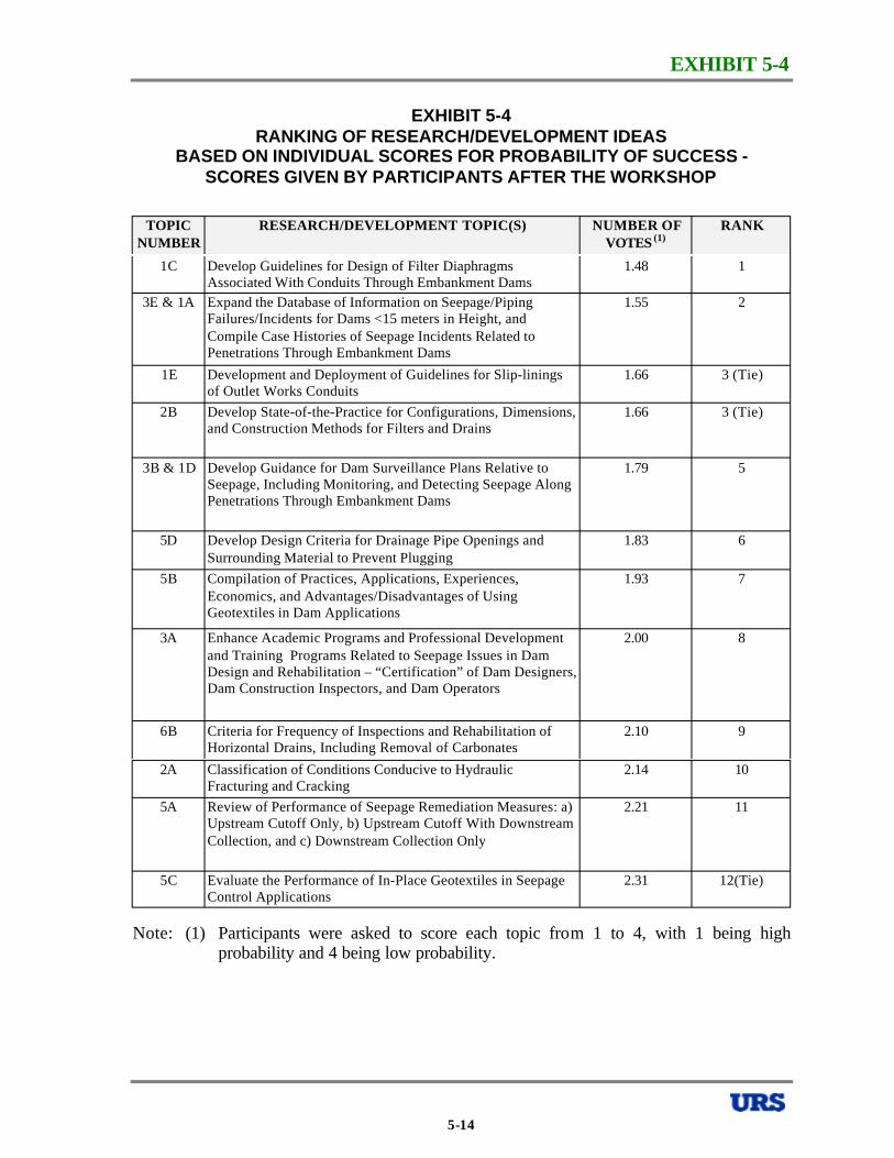
EXHIBIT 5-4
EXHIBIT 5-4 RANKING OF RESEARCH/DEVELOPMENT IDEAS
BASED ON INDIVIDUAL SCORES FOR PROBABILITY OF SUCCESS SCORES GIVEN BY PARTICIPANTS AFTER THE WORKSHOP
TOPIC NUMBER
RESEARCH/DEVELOPMENT TOPIC(S) NUMBER OF VOTES (1)
RANK
1C Develop Guidelines for Design of Filter Diaphragms 1.48 1 Associated With Conduits Through Embankment Dams
3E & 1A Expand the Database of Information on Seepage/Piping 1.55 2 Failures/Incidents for Dams <15 meters in Height, and Compile Case Histories of Seepage Incidents Related to Penetrations Through Embankment Dams
1E Development and Deployment of Guidelines for Slip-linings 1.66 3 (Tie) of Outlet Works Conduits
2B Develop State-of-the-Practice for Configurations, Dimensions, 1.66 3 (Tie) and Construction Methods for Filters and Drains
3B & 1D Develop Guidance for Dam Surveillance Plans Relative to 1.79 5 Seepage, Including Monitoring, and Detecting Seepage Along Penetrations Through Embankment Dams
5D Develop Design Criteria for Drainage Pipe Openings and 1.83 6 Surrounding Material to Prevent Plugging
5B Compilation of Practices, Applications, Experiences, 1.93 7 Economics, and Advantages/Disadvantages of Using Geotextiles in Dam Applications
3A Enhance Academic Programs and Professional Development 2.00 8 and Training Programs Related to Seepage Issues in Dam Design and Rehabilitation – “Certification” of Dam Designers, Dam Construction Inspectors, and Dam Operators
6B Criteria for Frequency of Inspections and Rehabilitation of 2.10 9 Horizontal Drains, Including Removal of Carbonates
2A Classification of Conditions Conducive to Hydraulic 2.14 10 Fracturing and Cracking
5A Review of Performance of Seepage Remediation Measures: a) 2.21 11 Upstream Cutoff Only, b) Upstream Cutoff With Downstream Collection, and c) Downstream Collection Only
5C Evaluate the Performance of In-Place Geotextiles in Seepage 2.31 12(Tie) Control Applications
Note: (1) Participants were asked to score each topic from 1 to 4, with 1 being high probability and 4 being low probability.
5-14
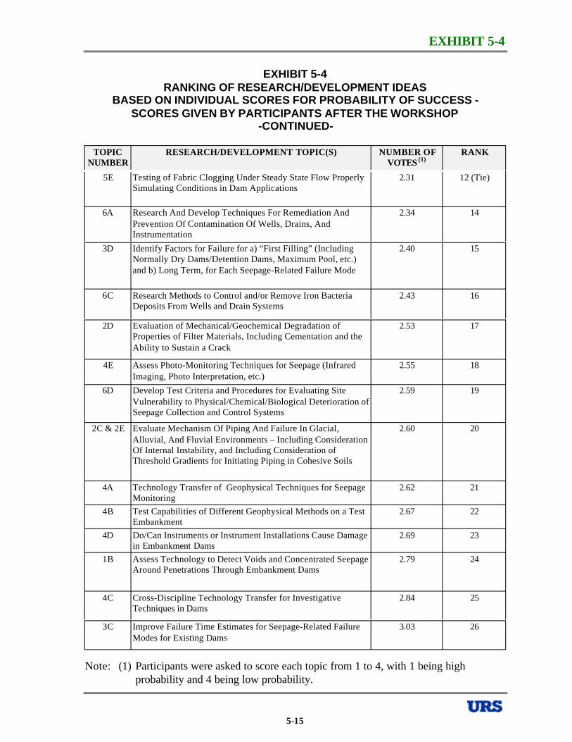
EXHIBIT 5-4
EXHIBIT 5-4 RANKING OF RESEARCH/DEVELOPMENT IDEAS
BASED ON INDIVIDUAL SCORES FOR PROBABILITY OF SUCCESS SCORES GIVEN BY PARTICIPANTS AFTER THE WORKSHOP
-CONTINUED
TOPIC NUMBER
RESEARCH/DEVELOPMENT TOPIC(S) NUMBER OF VOTES (1)
RANK
5E Testing of Fabric Clogging Under Steady State Flow Properly 2.31 12 (Tie) Simulating Conditions in Dam Applications
6A Research And Develop Techniques For Remediation And 2.34 14 Prevention Of Contamination Of Wells, Drains, And Instrumentation
3D Identify Factors for Failure for a) “First Filling” (Including 2.40 15 Normally Dry Dams/Detention Dams, Maximum Pool, etc.) and b) Long Term, for Each Seepage-Related Failure Mode
6C Research Methods to Control and/or Remove Iron Bacteria 2.43 16 Deposits From Wells and Drain Systems
2D Evaluation of Mechanical/Geochemical Degradation of 2.53 17 Properties of Filter Materials, Including Cementation and the Ability to Sustain a Crack
4E Assess Photo-Monitoring Techniques for Seepage (Infrared 2.55 18 Imaging, Photo Interpretation, etc.)
6D Develop Test Criteria and Procedures for Evaluating Site 2.59 19 Vulnerability to Physical/Chemical/Biological Deterioration of Seepage Collection and Control Systems
2C & 2E Evaluate Mechanism Of Piping And Failure In Glacial, 2.60 20 Alluvial, And Fluvial Environments – Including Consideration Of Internal Instability, and Including Consideration of Threshold Gradients for Initiating Piping in Cohesive Soils
4A Technology Transfer of Geophysical Techniques for Seepage 2.62 21 Monitoring
4B Test Capabilities of Different Geophysical Methods on a Test 2.67 22 Embankment
4D Do/Can Instruments or Instrument Installations Cause Damage 2.69 23 in Embankment Dams
1B Assess Technology to Detect Voids and Concentrated Seepage 2.79 24 Around Penetrations Through Embankment Dams
4C Cross-Discipline Technology Transfer for Investigative 2.84 25 Techniques in Dams
3C Improve Failure Time Estimates for Seepage-Related Failure 3.03 26 Modes for Existing Dams
Note: (1) Participants were asked to score each topic from 1 to 4, with 1 being high probability and 4 being low probability.
5-15
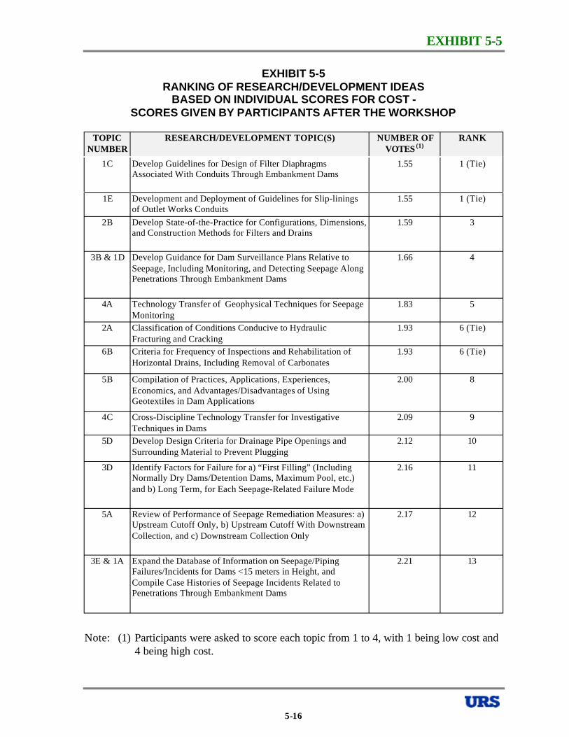
EXHIBIT 5-5
EXHIBIT 5-5 RANKING OF RESEARCH/DEVELOPMENT IDEAS
BASED ON INDIVIDUAL SCORES FOR COST SCORES GIVEN BY PARTICIPANTS AFTER THE WORKSHOP
TOPIC NUMBER
RESEARCH/DEVELOPMENT TOPIC(S) NUMBER OF VOTES (1)
RANK
1C Develop Guidelines for Design of Filter Diaphragms 1.55 1 (Tie) Associated With Conduits Through Embankment Dams
1E Development and Deployment of Guidelines for Slip-linings 1.55 1 (Tie) of Outlet Works Conduits
2B Develop State-of-the-Practice for Configurations, Dimensions, 1.59 3 and Construction Methods for Filters and Drains
3B & 1D Develop Guidance for Dam Surveillance Plans Relative to 1.66 4 Seepage, Including Monitoring, and Detecting Seepage Along Penetrations Through Embankment Dams
4A Technology Transfer of Geophysical Techniques for Seepage 1.83 5 Monitoring
2A Classification of Conditions Conducive to Hydraulic 1.93 6 (Tie) Fracturing and Cracking
6B Criteria for Frequency of Inspections and Rehabilitation of 1.93 6 (Tie) Horizontal Drains, Including Removal of Carbonates
5B Compilation of Practices, Applications, Experiences, 2.00 8 Economics, and Advantages/Disadvantages of Using Geotextiles in Dam Applications
4C Cross-Discipline Technology Transfer for Investigative 2.09 9 Techniques in Dams
5D Develop Design Criteria for Drainage Pipe Openings and 2.12 10 Surrounding Material to Prevent Plugging
3D Identify Factors for Failure for a) “First Filling” (Including 2.16 11 Normally Dry Dams/Detention Dams, Maximum Pool, etc.) and b) Long Term, for Each Seepage-Related Failure Mode
5A Review of Performance of Seepage Remediation Measures: a) 2.17 12 Upstream Cutoff Only, b) Upstream Cutoff With Downstream Collection, and c) Downstream Collection Only
3E & 1A Expand the Database of Information on Seepage/Piping 2.21 13 Failures/Incidents for Dams <15 meters in Height, and Compile Case Histories of Seepage Incidents Related to Penetrations Through Embankment Dams
Note: (1) Participants were asked to score each topic from 1 to 4, with 1 being low cost and 4 being high cost.
5-16
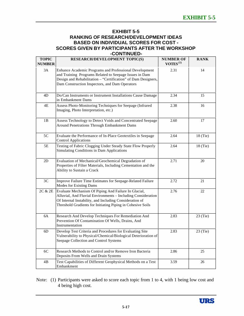
EXHIBIT 5-5
EXHIBIT 5-5 RANKING OF RESEARCH/DEVELOPMENT IDEAS
BASED ON INDIVIDUAL SCORES FOR COST SCORES GIVEN BY PARTICIPANTS AFTER THE WORKSHOP
-CONTINUEDTOPIC
NUMBER RESEARCH/DEVELOPMENT TOPIC(S) NUMBER OF
VOTES (1) RANK
3A Enhance Academic Programs and Professional Development 2.31 14 and Training Programs Related to Seepage Issues in Dam Design and Rehabilitation – “Certification” of Dam Designers, Dam Construction Inspectors, and Dam Operators
4D Do/Can Instruments or Instrument Installations Cause Damage 2.34 15 in Embankment Dams
4E Assess Photo-Monitoring Techniques for Seepage (Infrared 2.38 16 Imaging, Photo Interpretation, etc.)
1B Assess Technology to Detect Voids and Concentrated Seepage 2.60 17 Around Penetrations Through Embankment Dams
5C Evaluate the Performance of In-Place Geotextiles in Seepage 2.64 18 (Tie) Control Applications
5E Testing of Fabric Clogging Under Steady State Flow Properly 2.64 18 (Tie) Simulating Conditions in Dam Applications
2D Evaluation of Mechanical/Geochemical Degradation of 2.71 20 Properties of Filter Materials, Including Cementation and the Ability to Sustain a Crack
3C Improve Failure Time Estimates for Seepage-Related Failure 2.72 21 Modes for Existing Dams
2C & 2E Evaluate Mechanism Of Piping And Failure In Glacial, 2.76 22 Alluvial, And Fluvial Environments – Including Consideration Of Internal Instability, and Including Consideration of Threshold Gradients for Initiating Piping in Cohesive Soils
6A Research And Develop Techniques For Remediation And 2.83 23 (Tie) Prevention Of Contamination Of Wells, Drains, And Instrumentation
6D Develop Test Criteria and Procedures for Evaluating Site 2.83 23 (Tie) Vulnerability to Physical/Chemical/Biological Deterioration of Seepage Collection and Control Systems
6C Research Methods to Control and/or Remove Iron Bacteria 2.86 25 Deposits From Wells and Drain Systems
4B Test Capabilities of Different Geophysical Methods on a Test 3.59 26 Embankment
Note: (1) Participants were asked to score each topic from 1 to 4, with 1 being low cost and 4 being high cost.
5-17
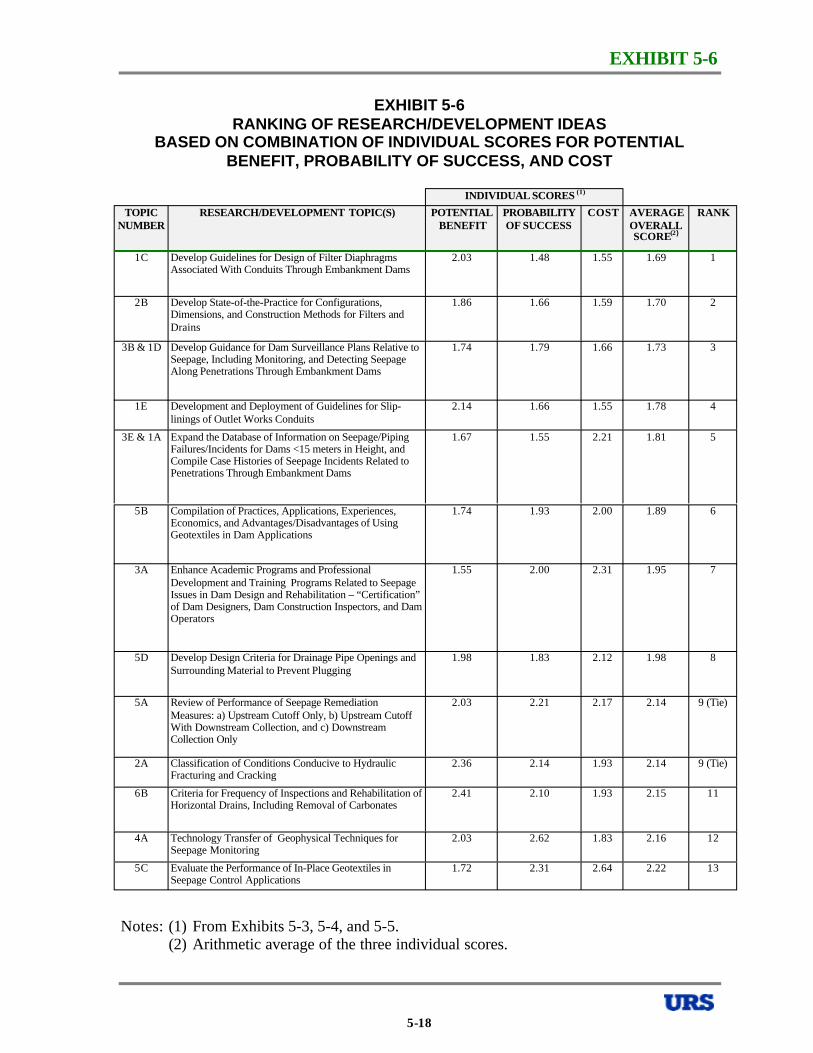
EXHIBIT 5-6
EXHIBIT 5-6 RANKING OF RESEARCH/DEVELOPMENT IDEAS
BASED ON COMBINATION OF INDIVIDUAL SCORES FOR POTENTIAL BENEFIT, PROBABILITY OF SUCCESS, AND COST
INDIVIDUAL SCORES (1)
TOPIC NUMBER
RESEARCH/DEVELOPMENT TOPIC(S) POTENTIAL BENEFIT
PROBABILITY OF SUCCESS
COST AVERAGE OVERALL SCORE(2 )
RANK
1C Develop Guidelines for Design of Filter Diaphragms Associated With Conduits Through Embankment Dams
2.03 1.48 1.55 1.69 1
2B Develop State-of-the-Practice for Configurations, Dimensions, and Construction Methods for Filters and Drains
1.86 1.66 1.59 1.70 2
3B & 1D Develop Guidance for Dam Surveillance Plans Relative to Seepage, Including Monitoring, and Detecting Seepage Along Penetrations Through Embankment Dams
1.74 1.79 1.66 1.73 3
1E Development and Deployment of Guidelines for Slip-linings of Outlet Works Conduits
2.14 1.66 1.55 1.78 4
3E & 1A Expand the Database of Information on Seepage/Piping Failures/Incidents for Dams <15 meters in Height, and Compile Case Histories of Seepage Incidents Related to Penetrations Through Embankment Dams
1.67 1.55 2.21 1.81 5
5B Compilation of Practices, Applications, Experiences, Economics, and Advantages/Disadvantages of Using Geotextiles in Dam Applications
1.74 1.93 2.00 1.89 6
3A Enhance Academic Programs and Professional
Issues in Dam Design and Rehabilitation – “Certification” of Dam Designers, Dam Construction Inspectors, and Dam Operators
1.55 2.00 2.31 1.95 7
5D Develop Design Criteria for Drainage Pipe Openings and Surrounding Material to Prevent Plugging
1.98 1.83 2.12 1.98 8
5A Review of Performance of Seepage Remediation Measures: a) Upstream Cutoff Only, b) Upstream Cutoff With Downstream Collection, and c) Downstream Collection Only
2.03 2.21 2.17 2.14 9 (Tie)
2A Classification of Conditions Conducive to Hydraulic Fracturing and Cracking
2.36 2.14 1.93 2.14 9 (Tie)
6B Criteria for Frequency of Inspections and Rehabilitation of Horizontal Drains, Including Removal of Carbonates
2.41 2.10 1.93 2.15 11
4A Seepage Monitoring
2.03 2.62 1.83 2.16 12
5C Evaluate the Performance of In-Place Geotextiles in Seepage Control Applications
1.72 2.31 2.64 2.22 13
Development and Training Programs Related to Seepage
Technology Transfer of Geophysical Techniques for
Notes: (1) From Exhibits 5-3, 5-4, and 5-5. (2) Arithmetic average of the three individual scores.
5-18
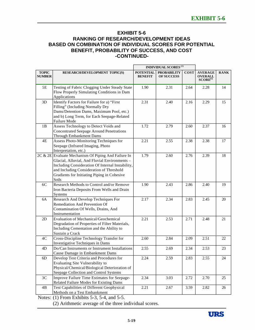
EXHIBIT 5-6
EXHIBIT 5-6 RANKING OF RESEARCH/DEVELOPMENT IDEAS
BASED ON COMBINATION OF INDIVIDUAL SCORES FOR POTENTIAL BENEFIT, PROBABILITY OF SUCCESS, AND COST
-CONTINUED
INDIVIDUAL SCORES (1)
TOPIC NUMBER
RESEARCH/DEVELOPMENT TOPIC(S) POTENTIAL BENEFIT
PROBABILITY OF SUCCESS
COST AVERAGE OVERALL SCORE(2 )
RANK
5E Testing of Fabric Clogging Under Steady State Flow Properly Simulating Conditions in Dam Applications
1.90 2.31 2.64 2.28 14
3D Identify Factors for Failure for a) “First Filling” (Including Normally Dry Dams/Detention Dams, Maximum Pool, etc.) and b) Long Term, for Each Seepage-Related Failure Mode
2.31 2.40 2.16 2.29 15
1B Assess Technology to Detect Voids and Concentrated Seepage Around Penetrations Through Embankment Dams
1.72 2.79 2.60 2.37 16
4E Assess Photo-Monitoring Techniques for Seepage (Infrared Imaging, Photo Interpretation, etc.)
2.21 2.55 2.38 2.38 17
Glacial, Alluvial, And Fluvial Environments – Including Consideration Of Internal Instability, and Including Consideration of Threshold Gradients for Initiating Piping in Cohesive Soils
1.79 2.60 2.76 2.39 18
6C Research Methods to Control and/or Remove Iron Bacteria Deposits From Wells and Drain Systems
1.90 2.43 2.86 2.40 19
6A Research And Develop Techniques For Remediation And Prevention Of Contamination Of Wells, Drains, And Instrumentation
2.17 2.34 2.83 2.45 20
2D Evaluation of Mechanical/Geochemical Degradation of Properties of Filter Materials, Including Cementation and the Ability to Sustain a Crack
2.21 2.53 2.71 2.48 21
4C Cross-Discipline Technology Transfer for Investigative Techniques in Dams
2.60 2.84 2.09 2.51 22
4D Do/Can Instruments or Instrument Installations Cause Damage in Embankment Dams
2.55 2.69 2.34 2.53 23
6D Develop Test Criteria and Procedures for Evaluating Site Vulnerability to Physical/Chemical/Biological Deterioration of Seepage Collection and Control Systems
2.24 2.59 2.83 2.55 24
3C Improve Failure Time Estimates for Seepage-Related Failure Modes for Existing Dams
2.34 3.03 2.72 2.70 25
4B Test Capabilities of Different Geophysical Methods on a Test Embankment
2.21 2.67 3.59 2.82 26
2C & 2E Evaluate Mechanism Of Piping And Failure In
Notes: (1) From Exhibits 5-3, 5-4, and 5-5. (2) Arithmetic average of the three individual scores.
5-19
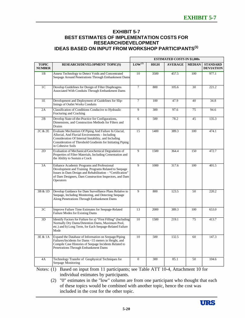
EXHIBIT 5-7
EXHIBIT 5-7 BEST ESTIMATES OF IMPLEMENTATION COSTS FOR
RESEARCH/DEVELOPMENT IDEAS BASED ON INPUT FROM WORKSHOP PARTICIPANTS(1)
ESTIMATED COSTS IN $1,000s
TOPIC NUMBER
RESEARCH/DEVELOPMENT TOPIC(S) LOW(2) HIGH AVERAGE MEDIAN STANDARD DEVIATION
1B Assess Technology to Detect Voids and Concentrated Seepage Around Penetrations Through Embankment Dams
10 3500 457.5 100 977.1
1C Develop Guidelines for Design of Filter Diaphragms Associated With Conduits Through Embankment Dams
7 800 105.6 30 221.2
1E Development and Deployment of Guidelines for Slip-linings of Outlet Works Conduits
7 100 47.9 40 34.8
2A Classification of Conditions Conducive to Hydraulic Fracturing and Cracking
9 300 97.6 75 94.6
2B Develop State-of-the-Practice for Configurations, Dimensions, and Construction Methods for Filters and Drains
6 500 78.2 45 135.3
2C & 2E Evaluate Mechanism Of Piping And Failure In Glacial, Alluvial, And Fluvial Environments – Including Consideration Of Internal Instability, and Including Consideration of Threshold Gradients for Initiating Piping in Cohesive Soils
15 1400 389.3 100 474.1
2D Evaluation of Mechanical/Geochemical Degradation of Properties of Filter Materials, Including Cementation and the Ability to Sustain a Crack
9 1500 364.4 150 472.7
3A Enhance Academic Programs and Professional
Issues in Dam Design and Rehabilitation – “Certification” of Dam Designers, Dam Construction Inspectors, and Dam Operators
9 1000 317.6 100 401.5
3B & 1D Develop Guidance for Dam Surveillance Plans Relative to Seepage, Including Monitoring, and Detecting Seepage Along Penetrations Through Embankment Dams
9 800 123.5 50 220.2
3C Improve Failure Time Estimates for Seepage-Related Failure Modes for Existing Dams
13 2000 389.3 100 653.0
3D Identify Factors for Failure for a) “First Filling” (Including Normally Dry Dams/Detention Dams, Maximum Pool, etc.) and b) Long Term, for Each Seepage-Related Failure Mode
10 1500 219.1 75 413.7
3E & 1A Expand the Database of Information on Seepage/Piping Failures/Incidents for Dams <15 meters in Height, and Compile Case Histories of Seepage Incidents Related to Penetrations Through Embankment Dams
10 500 132.5 60 147.3
Development and Training Programs Related to Seepage
4A Seepage Monitoring
0 300 85.1 50 104.6Technology Transfer of Geophysical Techniques for
Notes: (1) Based on input from 11 participants; see Table ATT 10-4, Attachment 10 for individual estimates by participants.
(2) "0" estimates in the "low" column are from one participant who thought that each of these topics would be combined with another topic, hence the cost was included in the cost for the other topic.
5-20
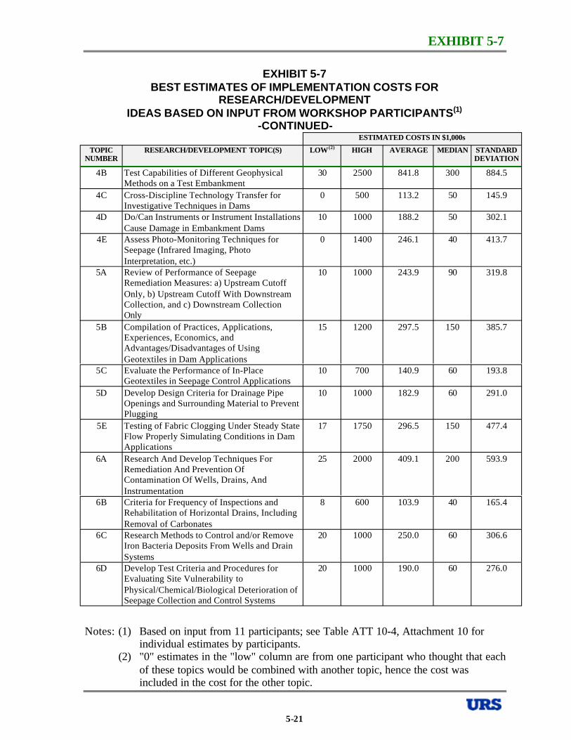
EXHIBIT 5-7
EXHIBIT 5-7 BEST ESTIMATES OF IMPLEMENTATION COSTS FOR
RESEARCH/DEVELOPMENT IDEAS BASED ON INPUT FROM WORKSHOP PARTICIPANTS(1)
-CONTINUEDESTIMATED COSTS IN $1,000s
TOPIC NUMBER
RESEARCH/DEVELOPMENT TOPIC(S) LOW(2) HIGH AVERAGE MEDIAN STANDARD DEVIATION
4B Test Capabilities of Different Geophysical Methods on a Test Embankment
30 2500 841.8 300 884.5
4C Cross-Discipline Technology Transfer for Investigative Techniques in Dams
0 500 113.2 50 145.9
4D Do/Can Instruments or Instrument Installations Cause Damage in Embankment Dams
10 1000 188.2 50 302.1
4E Assess Photo-Monitoring Techniques for Seepage (Infrared Imaging, Photo Interpretation, etc.)
0 1400 246.1 40 413.7
5A Review of Performance of Seepage Remediation Measures: a) Upstream Cutoff Only, b) Upstream Cutoff With Downstream Collection, and c) Downstream Collection Only
10 1000 243.9 90 319.8
5B Compilation of Practices, Applications, Experiences, Economics, and Advantages/Disadvantages of Using Geotextiles in Dam Applications
15 1200 297.5 150 385.7
5C Evaluate the Performance of In-Place Geotextiles in Seepage Control Applications
10 700 140.9 60 193.8
5D Develop Design Criteria for Drainage Pipe Openings and Surrounding Material to Prevent Plugging
10 1000 182.9 60 291.0
5E Testing of Fabric Clogging Under Steady State Flow Properly Simulating Conditions in Dam Applications
17 1750 296.5 150 477.4
6A Research And Develop Techniques For Remediation And Prevention Of Contamination Of Wells, Drains, And Instrumentation
25 2000 409.1 200 593.9
6B Criteria for Frequency of Inspections and Rehabilitation of Horizontal Drains, Including Removal of Carbonates
8 600 103.9 40 165.4
6C Research Methods to Control and/or Remove Iron Bacteria Deposits From Wells and Drain Systems
20 1000 250.0 60 306.6
6D Develop Test Criteria and Procedures for Evaluating Site Vulnerability to Physical/Chemical/Biological Deterioration of Seepage Collection and Control Systems
20 1000 190.0 60 276.0
Notes: (1) Based on input from 11 participants; see Table ATT 10-4, Attachment 10 for individual estimates by participants.
(2) "0" estimates in the "low" column are from one participant who thought that each of these topics would be combined with another topic, hence the cost was included in the cost for the other topic.
5-21
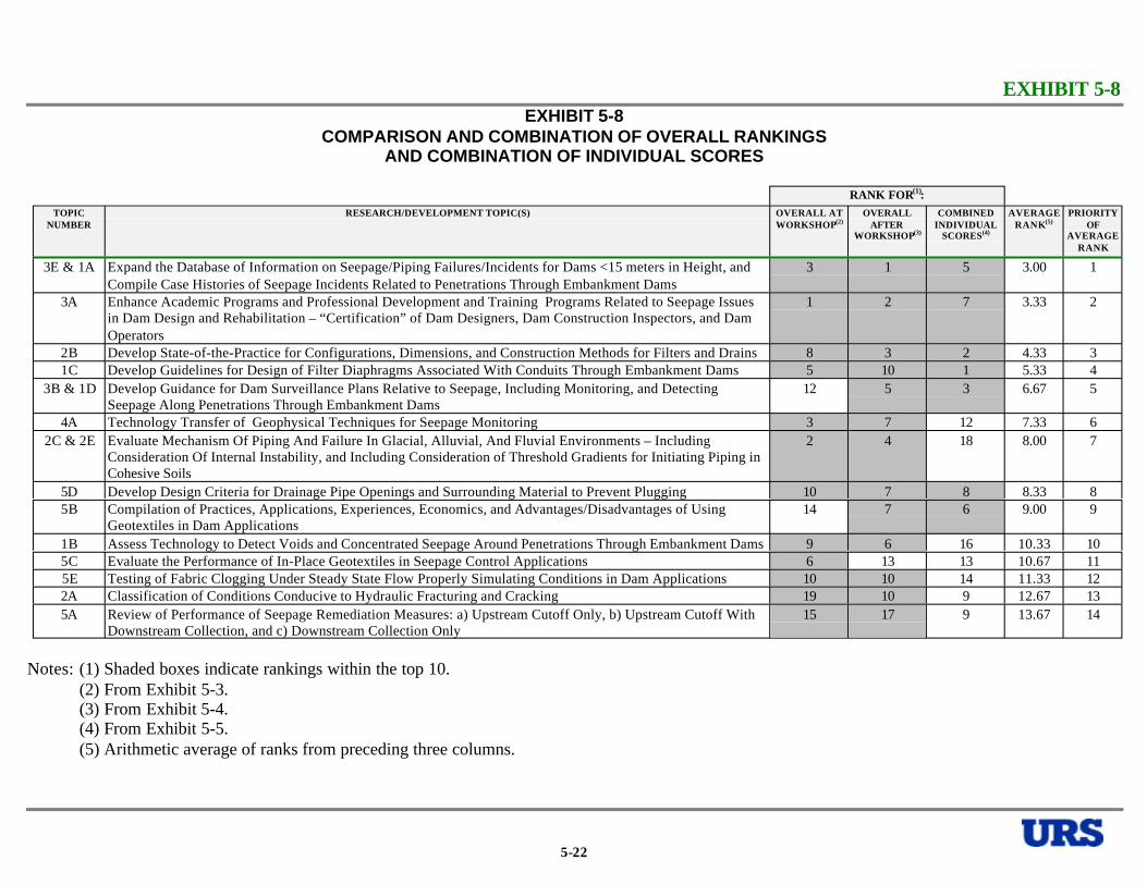
EXHIBIT 5-8 EXHIBIT 5-8
COMPARISON AND COMBINATION OF OVERALL RANKINGS AND COMBINATION OF INDIVIDUAL SCORES
RANK FOR(1): TOPIC
NUMBER RESEARCH/DEVELOPMENT TOPIC(S) OVERALL AT
WORKSHOP(2) OVERALL
AFTER WORKSHOP(3)
COMBINED INDIVIDUAL
SCORES(4)
AVERAGE RANK(5)
PRIORITY OF
AVERAGE RANK
3E & 1A Expand the Database of Information on Seepage/Piping Failures/Incidents for Dams <15 meters in Height, and Compile Case Histories of Seepage Incidents Related to Penetrations Through Embankment Dams
3 1 5 3.00 1
3A in Dam Design and Rehabilitation – “Certification” of Dam Designers, Dam Construction Inspectors, and Dam Operators
1 2 7 3.33 2
2B Develop State-of-the-Practice for Configurations, Dimensions, and Construction Methods for Filters and Drains 8 3 2 4.33 3 1C Develop Guidelines for Design of Filter Diaphragms Associated With Conduits Through Embankment Dams 5 10 1 5.33 4
3B & 1D Develop Guidance for Dam Surveillance Plans Relative to Seepage, Including Monitoring, and Detecting Seepage Along Penetrations Through Embankment Dams
12 5 3 6.67 5
4A 3 7 12 7.33 6 2C & 2E Evaluate Mechanism Of Piping And Failure In Glacial, Alluvial, And Fluvial Environments – Including
Consideration Of Internal Instability, and Including Consideration of Threshold Gradients for Initiating Piping in Cohesive Soils
2 4 18 8.00 7
5D Develop Design Criteria for Drainage Pipe Openings and Surrounding Material to Prevent Plugging 10 7 8 8.33 8 5B Compilation of Practices, Applications, Experiences, Economics, and Advantages/Disadvantages of Using
Geotextiles in Dam Applications 14 7 6 9.00 9
1B Assess Technology to Detect Voids and Concentrated Seepage Around Penetrations Through Embankment Dams 9 6 16 10.33 10 5C Evaluate the Performance of In-Place Geotextiles in Seepage Control Applications 6 13 13 10.67 11 5E Testing of Fabric Clogging Under Steady State Flow Properly Simulating Conditions in Dam Applications 10 10 14 11.33 12 2A Classification of Conditions Conducive to Hydraulic Fracturing and Cracking 19 10 9 12.67 13 5A Review of Performance of Seepage Remediation Measures: a) Upstream Cutoff Only, b) Upstream Cutoff With
Downstream Collection, and c) Downstream Collection Only 15 17 9 13.67 14
Enhance Academic Programs and Professional Development and Training Programs Related to Seepage Issues
Technology Transfer of Geophysical Techniques for Seepage Monitoring
Notes: (1) Shaded boxes indicate rankings within the top 10. (2) From Exhibit 5-3. (3) From Exhibit 5-4. (4) From Exhibit 5-5. (5) Arithmetic average of ranks from preceding three columns.
5-22
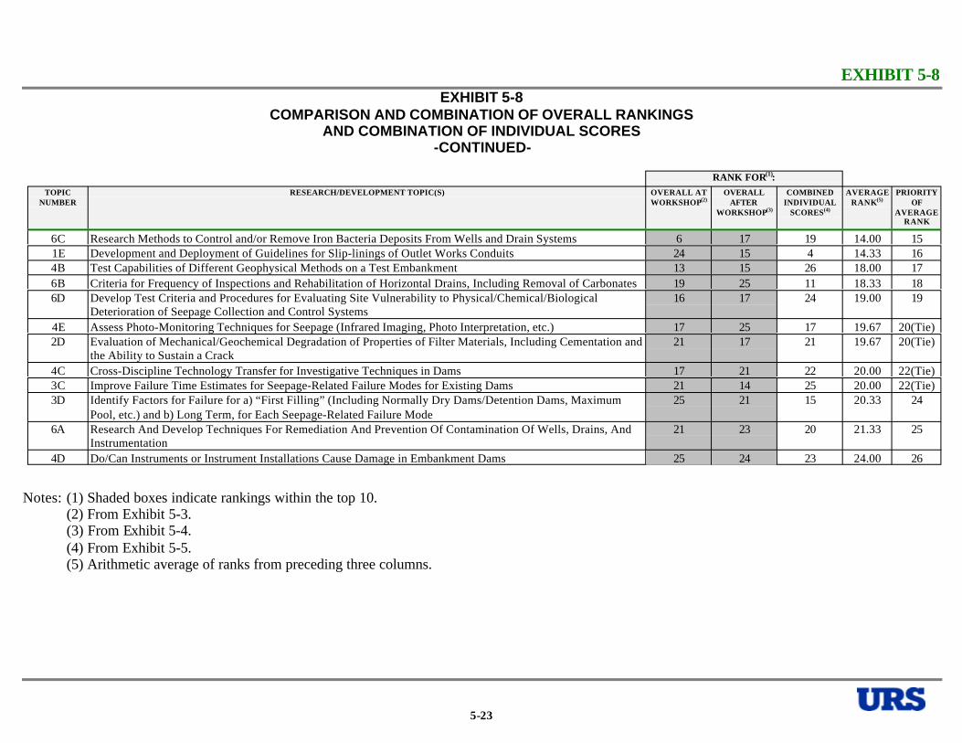
EXHIBIT 5-8 EXHIBIT 5-8
COMPARISON AND COMBINATION OF OVERALL RANKINGS AND COMBINATION OF INDIVIDUAL SCORES
-CONTINUED
RANK FOR(1): TOPIC
NUMBER RESEARCH/DEVELOPMENT TOPIC(S) OVERALL AT
WORKSHOP(2) OVERALL
AFTER WORKSHOP(3)
COMBINED INDIVIDUAL
SCORES(4)
AVERAGE RANK(5)
PRIORITY OF
AVERAGE RANK
6C Research Methods to Control and/or Remove Iron Bacteria Deposits From Wells and Drain Systems 6 17 19 14.00 15 1E Development and Deployment of Guidelines for Slip-linings of Outlet Works Conduits 24 15 4 14.33 16 4B Test Capabilities of Different Geophysical Methods on a Test Embankment 13 15 26 18.00 17 6B Criteria for Frequency of Inspections and Rehabilitation of Horizontal Drains, Including Removal of Carbonates 19 25 11 18.33 18 6D Develop Test Criteria and Procedures for Evaluating Site Vulnerability to Physical/Chemical/Biological
Deterioration of Seepage Collection and Control Systems 16 17 24 19.00 19
4E Assess Photo-Monitoring Techniques for Seepage (Infrared Imaging, Photo Interpretation, etc.) 17 25 17 19.67 20(Tie) 2D Evaluation of Mechanical/Geochemical Degradation of Properties of Filter Materials, Including Cementation and
the Ability to Sustain a Crack 21 17 21 19.67 20(Tie)
4C Cross-Discipline Technology Transfer for Investigative Techniques in Dams 17 21 22 20.00 22(Tie) 3C Improve Failure Time Estimates for Seepage-Related Failure Modes for Existing Dams 21 14 25 20.00 22(Tie) 3D Identify Factors for Failure for a) “First Filling” (Including Normally Dry Dams/Detention Dams, Maximum
Pool, etc.) and b) Long Term, for Each Seepage-Related Failure Mode 25 21 15 20.33 24
6A Research And Develop Techniques For Remediation And Prevention Of Contamination Of Wells, Drains, And Instrumentation
21 23 20 21.33 25
4D Do/Can Instruments or Instrument Installations Cause Damage in Embankment Dams 25 24 23 24.00 26
Notes: (1) Shaded boxes indicate rankings within the top 10. (2) From Exhibit 5-3.(3) From Exhibit 5-4. (4) From Exhibit 5-5.(5) Arithmetic average of ranks from preceding three columns.
5-23
6.0 REFERENCES
6.0 REFERENCES
All of the white paper authors provided reference lists, which can be found at the back of each of the white papers, in Attachments 4 through 9.
In addition, a list of pertinent references was compiled and is included in Attachment 11. Most of this list was provided by Professor Robin Fell, one of the workshop participants, but his list was supplemented by contributions from other participants.
It should be noted that the reference lists included in this document should not be considered exhaustive. The existing literature related to seepage through embankment dams is incredibly voluminous, and it would not be practical to compile an exhaustive list. In addition, technical papers on the topic are regularly being published in journals and conference proceedings, and any reference list will quickly become out-of-date.
6-1

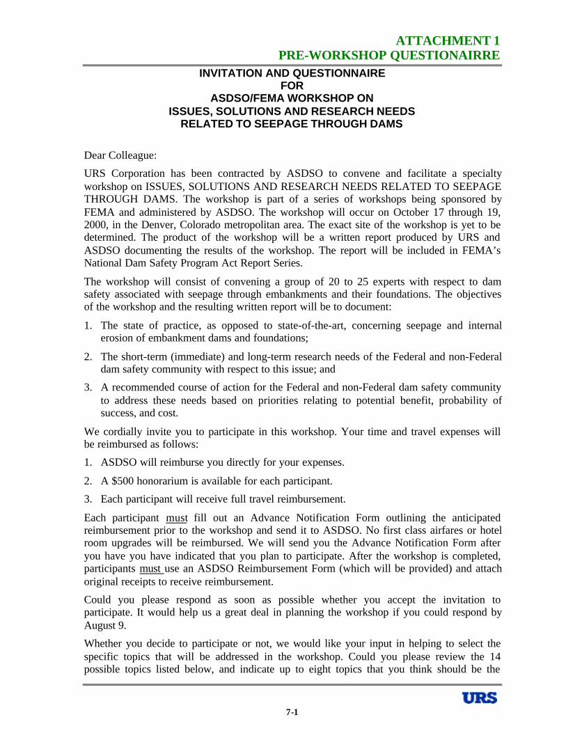
ATTACHMENT 1 PRE-WORKSHOP QUESTIONAIRRE
INVITATION AND QUESTIONNAIRE FOR
ASDSO/FEMA WORKSHOP ON ISSUES, SOLUTIONS AND RESEARCH NEEDS
RELATED TO SEEPAGE THROUGH DAMS
Dear Colleague:
URS Corporation has been contracted by ASDSO to convene and facilitate a specialty workshop on ISSUES, SOLUTIONS AND RESEARCH NEEDS RELATED TO SEEPAGE THROUGH DAMS. The workshop is part of a series of workshops being sponsored by FEMA and administered by ASDSO. The workshop will occur on October 17 through 19, 2000, in the Denver, Colorado metropolitan area. The exact site of the workshop is yet to be determined. The product of the workshop will be a written report produced by URS and ASDSO documenting the results of the workshop. The report will be included in FEMA’s National Dam Safety Program Act Report Series.
The workshop will consist of convening a group of 20 to 25 experts with respect to dam safety associated with seepage through embankments and their foundations. The objectives of the workshop and the resulting written report will be to document:
1. The state of practice, as opposed to state-of-the-art, concerning seepage and internal erosion of embankment dams and foundations;
2. The short-term (immediate) and long-term research needs of the Federal and non-Federal dam safety community with respect to this issue; and
3. A recommended course of action for the Federal and non-Federal dam safety community to address these needs based on priorities relating to potential benefit, probability of success, and cost.
We cordially invite you to participate in this workshop. Your time and travel expenses will be reimbursed as follows:
1. ASDSO will reimburse you directly for your expenses.
2. A $500 honorarium is available for each participant.
3. Each participant will receive full travel reimbursement.
Each participant must fill out an Advance Notification Form outlining the anticipated reimbursement prior to the workshop and send it to ASDSO. No first class airfares or hotel room upgrades will be reimbursed. We will send you the Advance Notification Form after you have you have indicated that you plan to participate. After the workshop is completed, participants must use an ASDSO Reimbursement Form (which will be provided) and attach original receipts to receive reimbursement.
Could you please respond as soon as possible whether you accept the invitation to participate. It would help us a great deal in planning the workshop if you could respond by August 9.
Whether you decide to participate or not, we would like your input in helping to select the specific topics that will be addressed in the workshop. Could you please review the 14 possible topics listed below, and indicate up to eight topics that you think should be the
7-1

ATTACHMENT 1 PRE-WORKSHOP QUESTIONAIRRE
highest priority for consideration at the workshop. In addition, if there are other topics that you think are equally important, but are not encompassed by the 14 listed topics, please list those in the space provided. The workshop will be focused on seepage related to embankment dams, so please confine your considerations to embankment dams. In considering the prioritization for possible topics please remember that one of the purposes of the workshop is to identify research needs. Consequently, not just the importance of the topic, but also the potential for short-term beneficial research, should be considered. In other words, are there topics, which might yield beneficial “low-hanging fruit” in the research field – research that is both relatively easily achieved and provides relatively important results.
SEEPAGE TOPICS QUESTIONNAIRE Mark Up to Possible Topics Eight Topics
Identification of potential seepage problems before construction. Failure modes associated with seepage and internal erosion. Inspection of dams for detection of seepage problems. Instrumentation and measurements for evaluation of seepage performance. Investigation of seepage problems/concerns at dams, including the use of geophysical techniques. Analysis of seepage flow, including two-dimensional and three-dimensional methods. Analysis of risks associated with seepage and internal erosion. Remediation of seepage problems through cutoff or reduction of flow, including the use of geotextiles. Remediation of seepage problems through collection and control of seepage, including the use of geosynthetics. Seepage control systems for new dams. Impacts of aging of seepage control/collection system components on seepage performance. Mechanism of particle movement and progression of internal erosion. Filter design criteria and observed performance (the concepts of no erosion and continuous erosion boundaries for evaluating filter compatibility). Potential seepage problems and solutions associated with penetrations through embankment dams (e.g., outlet works conduits).
List below any other topics that you believe are of equal importance to the eight that you have marked, but are not encompassed by the 14 topics listed above:
Thank you for your help, and I hope that you can participate.
John W. France, PE Workshop Facilitator, URS Corporation
7-2
ATTACHMENT 2 RESPONSE TO PRE-WORKSHOP QUESTIONNAIRE
ADDITIONAL COMMENTS FROM RESPONDENTS ASDSO/FEMA WORKSHOP ON SEEPAGE THROUGH EMBANKMENT DAMS
AUGUST 22, 2000
RESPONDENT A 1. I recently obtained a copy of “Analysis of Embankment Dam Incidents” by Foster, et al,
University of New South Wales, September 1998. The study included a population of 11,192 embankment dams, all “large” as defined by ICOLD and all constructed prior to 1986. Dams in China were excluded as were dams in Japan constructed prior to 1930 because of lack of reliable data. Of the 11,192 embankment dams, a total of 136 or 1.2 percent failed. Failure is defined as “collapse or movement of part of a dam or its foundation, so that the dam cannot retain water”. Of the 136 failures, 59 failed as a result of piping and 46 failed by overtopping. Only 2 failed by earthquake or liquefaction. 88 out of 2356 (3.8 percent) large embankment dams constructed before 1950 failed; 48 out of 8836 (0.5 percent) large embankment dams constructed between 1950 and 1986 failed. These are amazing statistics:
a. Over 1 percent of all large embankment dams failed over their lifetime.
b. One large embankment dam in 200 constructed after 1950 and prior to 1986 failed.
c. Nearly half of all failures were triggered by piping.
The importance of seepage control in new and existing embankment dams cannot be overemphasized.
I was not fully aware that the embankment dam profession had such a poor performance record. One percent is, in my opinion, extremely high. Do one percent of other major civil engineering structures fail disastrously? I don’t think so, but I don't know for sure.
2. ICOLD Bulletin 95 concerning the use of granular filters in embankment dams is a good reference on current design criteria.
RESPONDENT B We need to assemble a compendium of seepage related failure case histories with characteristics that would have predicted failure if identified during the design or during operation. There is a developing loss of experienced designers and inspectors and we need to provide young engineers with a text book that summarizes our experience.
RESPONDENT C Statistical study of historical failure mechanisms for small dams (follow-on to the UNSW study for large dams).
Note that the topic of “penetrations through embankments” was a FEMA sponsored workshop and seminar. If we work on that one it should build on what was done there. have the publication from that work.
7-3
I
ATTACHMENT 2 RESPONSE TO PRE-WORKSHOP QUESTIONNAIRE
RESPONDENT D Identification of deficiencies in existing dams and possible remediation.
Application of geophysical techniques to the investigation of concentrated seepage flow in embankments and foundations and karst formations.
RESPONDENT E Training of civil engineers in dam design. (I am not sure how to approach this one, but in my experience, many of the recent dams that have failed by piping have been designed by civil engineers who did not have any clue how to design to prevent piping. Many such dams are small dams built by unsophisticated owners who hire a local civil engineer because he is cheap. Maybe the topic should be "how to train owners to understand that they need to hire competent dam designers.")
Training of field inspectors to be aware of problems that show up during construction, but that are not anticipated during design. (Teton Dam)
RESPONDENT F As for my thoughts on possible topics, I've included, below, my selections from the list included with your questionnaire. My philosophy follows that of many others - - It is best to be proactive on prevention (which is facilitated by understanding the processes involved). I, therefore, feel the first topic is of special importance. However, since existing structures outnumber the dams planned for construction, there needs to be focus on methods for the detection of possible problems, or even realizing that there are specific potential issues at a structure. These include effects of time on the seepage regime (including the structure, foundation, and changes in reservoir operation), as well as the monitoring and control systems. Of course, once an issue is identified, the aspect of remediation comes to the fore. I think there are quite a few opportunities for research in the areas of problem identification and monitoring, and in the remediation arena. Your suggested topics should provide for some interesting and informative discussions.
However, an additional topic that would interest me would be an idea that has generated some recent discussions in our office. The subject: reexamining filter criteria for drainage systems utilizing slotted or holed drain pipe, possibly developing new criteria. Discussion on design of such features would also be covered, including use of geotextiles (drain pipe in two stage (gravel/sand) envelope; drain pipe wrapped w/ geotextile in sand envelope; drain pipe in gravel envelope enwrapped w/ geotextile). This subject somewhat ties in with several of the topics on your original list. This would also be a fairly easily implemented research subject.
RESPONDENT G (a) Modeling the whole internal erosion and piping process, from initiation of erosion,
continuation, progression to form a pipe, and formation of a breach mechanism. (It is the details of the whole process, which separates incidents from failures).
(b) Factors that affect the likelihood of initiation and progression and how these may be used to assist in distinguishing between dams which are more likely to experience accidents and those which are more likely to fail.
7-4
ATTACHMENT 2 RESPONSE TO PRE-WORKSHOP QUESTIONNAIRE
(c) The mechanics of erosion and piping in alluvial and fluvioglacial foundation - once again with a view to being able to separate incidents from failures.
(d) Management of internal erosion and piping issues in small dams.
RESPONDENT H The Workshop should clarify whether or not tailings dams are being considered. If they are emission criteria become more restrictive and design for minimal seepage, even zero discharge, needs to be considered.
RESPONDENT I 1. Basic Principles - (Source or cause of seepage problems associated with existing dams
and filter/drain design principles to solve these problems) – Piping/internal erosion, cracking, dispersion, role of filters.
2. Inspection, Investigation, and Detection of Seepage or Problems Associated with Seepage.
3. Monitoring - Seepage and sediment quantity measurements - Piezometers - what can you tell from piezometer data - when to use - how to evaluate data - monitoring with reservoir level changes, rainfall, or other events.
RESPONDENT J Case histories for training – slurry trench, etc. Rehabilitation of relief wells. Maintenance of drains – iron ochre problem.
RESPONDENT K Identification and analyses of effects of anisotropic permeability (could be grouped in with the “analysis of seepage flow, etc.” topic).
RESPONDENT L Time frames associated with piping induced failures for use in estimating warning time:
1. Signs of an impending piping problem. 2. Estimating the elapsed time from the first sign of a piping problem until failure begins. 3. timating the time required to fully develop a breach from a piping induced failure.
RESPONDENT M Evaluation and Remediation of Incompatible Material Zones Within Existing Dams.
Construction Treatments for the Near-Surface Rock Zone and the Soil-Rock Interface.
Update on Dispersive Soil Problems.
7-5
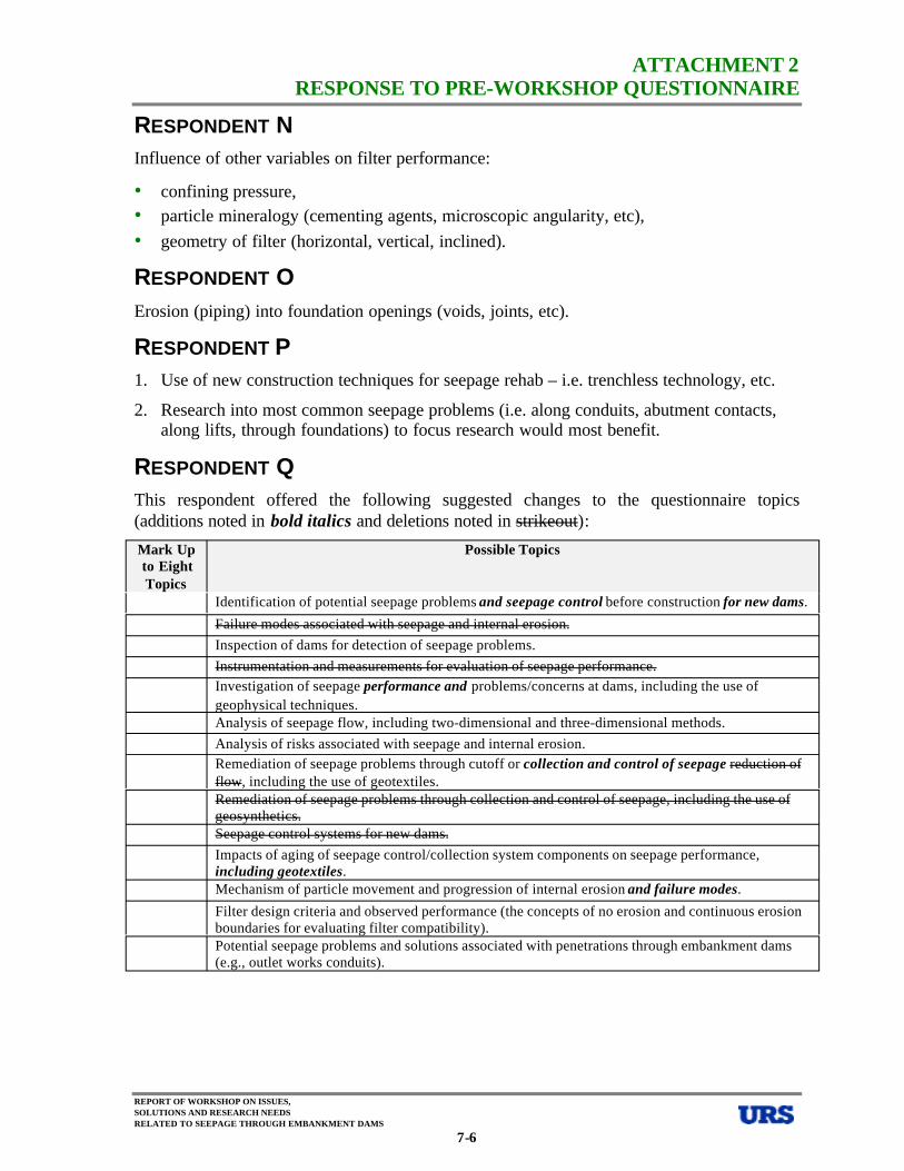
ATTACHMENT 2 RESPONSE TO PRE-WORKSHOP QUESTIONNAIRE
RESPONDENT N Influence of other variables on filter performance:
• confining pressure, • particle mineralogy (cementing agents, microscopic angularity, etc), • geometry of filter (horizontal, vertical, inclined).
RESPONDENT O Erosion (piping) into foundation openings (voids, joints, etc).
RESPONDENT P 1. Use of new construction techniques for seepage rehab – i.e. trenchless technology, etc.
2. Research into most common seepage problems (i.e. along conduits, abutment contacts, along lifts, through foundations) to focus research would most benefit.
RESPONDENT Q This respondent offered the following suggested changes to the questionnaire topics (additions noted in bold italics and deletions noted in strikeout):
Mark Up Possible Topics to Eight Topics
Identification of potential seepage problems and seepage control before construction for new dams.
Failure modes associated with seepage and internal erosion. Inspection of dams for detection of seepage problems. Instrumentation and measurements for evaluation of seepage performance. Investigation of seepage performance and problems/concerns at dams, including the use of geophysical techniques. Analysis of seepage flow, including two-dimensional and three-dimensional methods. Analysis of risks associated with seepage and internal erosion. Remediation of seepage problems through cutoff or collection and control of seepage reduction of flow, including the use of geotextiles. Remediation of seepage problems through collection and control of seepage, including the use of geosynthetics. Seepage control systems for new dams. Impacts of aging of seepage control/collection system components on seepage performance, including geotextiles. Mechanism of particle movement and progression of internal erosion and failure modes.
Filter design criteria and observed performance (the concepts of no erosion and continuous erosion boundaries for evaluating filter compatibility). Potential seepage problems and solutions associated with penetrations through embankment dams (e.g., outlet works conduits).
REPORT OF WORKSHOP ON ISSUES, SOLUTIONS AND RESEARCH NEEDS RELATED TO SEEPAGE THROUGH EMBANKMENT DAMS
7-6
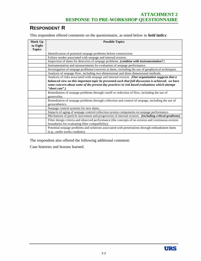
ATTACHMENT 2 RESPONSE TO PRE-WORKSHOP QUESTIONNAIRE
RESPONDENT R This respondent offered comments on the questionnaire, as noted below in bold italics:
Mark Up Possible Topics to Eight Topics
Identification of potential seepage problems before construction. Failure modes associated with seepage and internal erosion. Inspection of dams for detection of seepage problems. (combine with instrumentation? ) Instrumentation and measurements for evaluation of seepage performance. Investigation of seepage problems/concerns at dams, including the use of geophysical techniques. Analysis of seepage flow, including two-dimensional and three-dimensional methods. Analysis of risks associated with seepage and internal erosion. (Our organization suggests that a balanced view on this important topic be presented such that full discussion is achieved; we have some concern about some of the present day practices in risk based evaluations which attempt “short cuts”.) Remediation of seepage problems through cutoff or reduction of flow, including the use of geotextiles. Remediation of seepage problems through collection and control of seepage, including the use of geosynthetics. Seepage control systems for new dams. Impacts of aging of seepage control/collection system components on seepage performance. Mechanism of particle movement and progression of internal erosion. (including critical gradients) Filter design criteria and observed performance (the concepts of no erosion and continuous erosion boundaries for evaluating filter compatibility). Potential seepage problems and solutions associated with penetrations through embankment dams (e.g., outlet works conduits).
The respondent also offered the following additional comment:
Case histories and lessons learned.
7-7
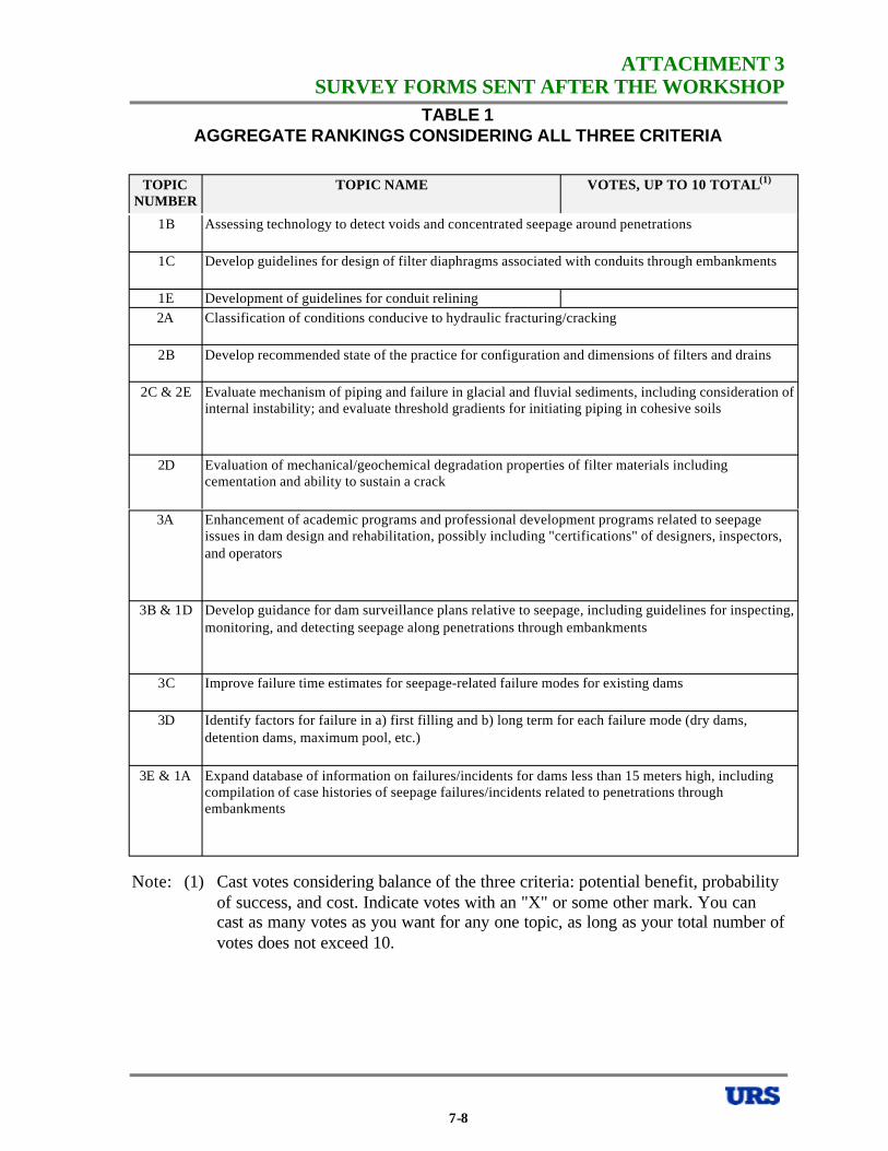
ATTACHMENT 3 SURVEY FORMS SENT AFTER THE WORKSHOP
TABLE 1 AGGREGATE RANKINGS CONSIDERING ALL THREE CRITERIA
TOPIC NUMBER
TOPIC NAME VOTES, UP TO 10 TOTAL(1)
1B Assessing technology to detect voids and concentrated seepage around penetrations
1C Develop guidelines for design of filter diaphragms associated with conduits through embankments
1E Development of guidelines for conduit relining 2A Classification of conditions conducive to hydraulic fracturing/cracking
2B Develop recommended state of the practice for configuration and dimensions of filters and drains
2C & 2E Evaluate mechanism of piping and failure in glacial and fluvial sediments, including consideration of internal instability; and evaluate threshold gradients for initiating piping in cohesive soils
2D Evaluation of mechanical/geochemical degradation properties of filter materials including cementation and ability to sustain a crack
3A Enhancement of academic programs and professional development programs related to seepage issues in dam design and rehabilitation, possibly including "certifications" of designers, inspectors, and operators
3B & 1D Develop guidance for dam surveillance plans relative to seepage, including guidelines for inspecting, monitoring, and detecting seepage along penetrations through embankments
3C Improve failure time estimates for seepage-related failure modes for existing dams
3D Identify factors for failure in a) first filling and b) long term for each failure mode (dry dams, detention dams, maximum pool, etc.)
3E & 1A Expand database of information on failures/incidents for dams less than 15 meters high, including compilation of case histories of seepage failures/incidents related to penetrations through embankments
Note: (1) Cast votes considering balance of the three criteria: potential benefit, probability of success, and cost. Indicate votes with an "X" or some other mark. You can cast as many votes as you want for any one topic, as long as your total number of votes does not exceed 10.
7-8
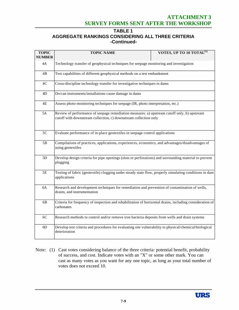
ATTACHMENT 3 SURVEY FORMS SENT AFTER THE WORKSHOP
TABLE 1 AGGREGATE RANKINGS CONSIDERING ALL THREE CRITERIA
-Continued-
TOPIC NUMBER
TOPIC NAME VOTES, UP TO 10 TOTAL(1)
4A Technology transfer of geophysical techniques for seepage monitoring and investigation
4B Test capabilities of different geophysical methods on a test embankment
4C Cross-discipline technology transfer for investigative techniques in dams
4D Do/can instruments/installations cause damage in dams
4E Assess photo-monitoring techniques for seepage (IR, photo interpretation, etc.)
5A Review of performance of seepage remediation measures: a) upstream cutoff only, b) upstream cutoff with downstream collection, c) downstream collection only
5C Evaluate performance of in-place geotextiles in seepage control applications
5B Compilations of practices, applications, experiences, economics, and advantages/disadvantages of using geotextiles
5D Develop design criteria for pipe openings (slots or perforations) and surrounding material to prevent plugging
5E Testing of fabric (geotextile) clogging under steady state flow, properly simulating conditions in dam applications
6A Research and development techniques for remediation and prevention of contamination of wells, drains, and instrumentation
6B Criteria for frequency of inspection and rehabilitation of horizontal drains, including consideration of carbonates
6C Research methods to control and/or remove iron bacteria deposits from wells and drain systems
6D Develop test criteria and procedures for evaluating site vulnerability to physical/chemical/biological deterioration
Note: (1) Cast votes considering balance of the three criteria: potential benefit, probability of success, and cost. Indicate votes with an "X" or some other mark. You can cast as many votes as you want for any one topic, as long as your total number of votes does not exceed 10.
7-9

ATTACHMENT 3 SURVEY FORMS SENT AFTER THE WORKSHOP
TABLE 2 RANKING USING THREE SEPARATE CRITERIA
TOPIC NUMBER
TOPIC NAME POTENTIAL BENEFIT
PROBABILITY OF SUCCESS
COST
RANK 1 to 4 (1) RANK 1 to 4 (2) RANK 1 to 4 (3)
1B Assessing technology to detect voids and concentrated seepage around penetrations
1C Develop guidelines for design of filter diaphragms associated with conduits through embankments
1E Development of guidelines for conduit relining 2A Classification of conditions conducive to
hydraulic fracturing/cracking 2B Develop recommended state of the practice for
configuration and dimensions of filters and drains 2C & 2E Evaluate mechanism of piping and failure in
glacial and fluvial sediments, including consideration of internal instability; and evaluate threshold gradients for initiating piping in cohesive soils
2D Evaluation of mechanical/geochemical degradation properties of filter materials including cementation and ability to sustain a crack
3A Enhancement of academic programs and professional development programs related to seepage issues in dam design and rehabilitation, possibly including "certifications" of designers, inspectors, and operators
3B & 1D Develop guidance for dam surveillance plans relative to seepage, including guidelines for inspecting, monitoring, and detecting seepage along penetrations through embankments
3C Improve failure time estimates for seepage-related failure modes for existing dams
3D Identify factors for failure in a) first filling and b) long term for each failure mode (dry dams, detention dams, maximum pool, etc.)
3E & 1A Expand database of information on failures/incidents for dams less than 15 meters high, including compilation of case histories of seepage failures/incidents related to penetrations through embankments
Notes: (1) 1 is most benefit and 4 is least benefit (2) 1 is high probability and 4 is low probability(3) 1 is low cost and 4 is high cost
7-10
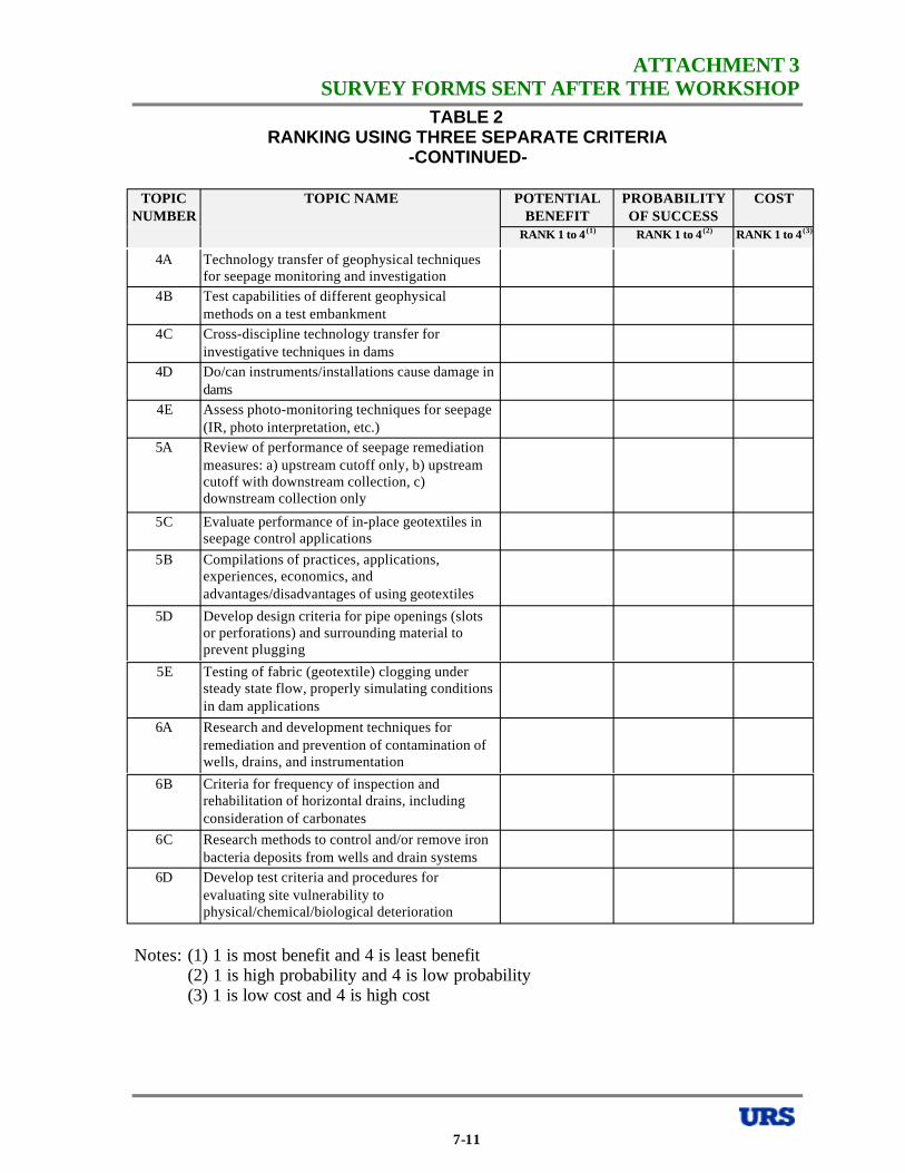
ATTACHMENT 3 SURVEY FORMS SENT AFTER THE WORKSHOP
TABLE 2 RANKING USING THREE SEPARATE CRITERIA
-CONTINUED
TOPIC NUMBER
TOPIC NAME POTENTIAL BENEFIT
PROBABILITY OF SUCCESS
COST
RANK 1 to 4 (1) RANK 1 to 4 (2) RANK 1 to 4 (3)
4A Technology transfer of geophysical techniques for seepage monitoring and investigation
4B Test capabilities of different geophysical methods on a test embankment
4C Cross-discipline technology transfer for investigative techniques in dams
4D Do/can instruments/installations cause damage in dams
4E Assess photo-monitoring techniques for seepage (IR, photo interpretation, etc.)
5A Review of performance of seepage remediation measures: a) upstream cutoff only, b) upstream cutoff with downstream collection, c) downstream collection only
5C Evaluate performance of in-place geotextiles in seepage control applications
5B Compilations of practices, applications, experiences, economics, and advantages/disadvantages of using geotextiles
5D Develop design criteria for pipe openings (slots or perforations) and surrounding material to prevent plugging
5E Testing of fabric (geotextile) clogging under steady state flow, properly simulating conditions in dam applications
6A Research and development techniques for remediation and prevention of contamination of wells, drains, and instrumentation
6B Criteria for frequency of inspection and rehabilitation of horizontal drains, including consideration of carbonates
6C Research methods to control and/or remove iron bacteria deposits from wells and drain systems
6D Develop test criteria and procedures for evaluating site vulnerability to physical/chemical/biological deterioration
Notes: (1) 1 is most benefit and 4 is least benefit (2) 1 is high probability and 4 is low probability(3) 1 is low cost and 4 is high cost
7-11
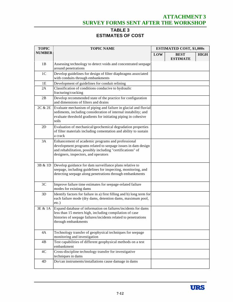
ATTACHMENT 3 SURVEY FORMS SENT AFTER THE WORKSHOP
TABLE 3 ESTIMATES OF COST
TOPIC TOPIC NAME ESTIMATED COST, $1,000s NUMBER LOW BEST
ESTIMATE HIGH
1B Assessing technology to detect voids and concentrated seepage around penetrations
1C Develop guidelines for design of filter diaphragms associated with conduits through embankments
1E Development of guidelines for conduit relining 2A Classification of conditions conducive to hydraulic
fracturing/cracking 2B Develop recommended state of the practice for configuration
and dimensions of filters and drains 2C & 2E Evaluate mechanism of piping and failure in glacial and fluvial
sediments, including consideration of internal instability; and evaluate threshold gradients for initiating piping in cohesive soils
2D Evaluation of mechanical/geochemical degradation properties of filter materials including cementation and ability to sustain a crack
3A Enhancement of academic programs and professional development programs related to seepage issues in dam design and rehabilitation, possibly including "certifications" of designers, inspectors, and operators
3B & 1D Develop guidance for dam surveillance plans relative to seepage, including guidelines for inspecting, monitoring, and detecting seepage along penetrations through embankments
3C Improve failure time estimates for seepage-related failure modes for existing dams
3D Identify factors for failure in a) first filling and b) long term for each failure mode (dry dams, detention dams, maximum pool, etc.)
3E & 1A Expand database of information on failures/incidents for dams less than 15 meters high, including compilation of case histories of seepage failures/incidents related to penetrations through embankments
4A Technology transfer of geophysical techniques for seepage monitoring and investigation
4B Test capabilities of different geophysical methods on a test embankment
4C Cross-discipline technology transfer for investigative techniques in dams
4D Do/can instruments/installations cause damage in dams
7-12
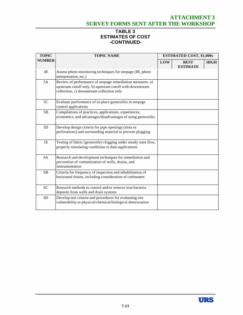
ATTACHMENT 3 SURVEY FORMS SENT AFTER THE WORKSHOP
TABLE 3 ESTIMATES OF COST
-CONTINUED
TOPIC TOPIC NAME ESTIMATED COST, $1,000s NUMBER LOW BEST
ESTIMATE HIGH
4E Assess photo-monitoring techniques for seepage (IR, photo interpretation, etc.)
5A Review of performance of seepage remediation measures: a) upstream cutoff only, b) upstream cutoff with downstream collection, c) downstream collection only
5C Evaluate performance of in-place geotextiles in seepage control applications
5B Compilations of practices, applications, experiences, economics, and advantages/disadvantages of using geotextiles
5D Develop design criteria for pipe openings (slots or perforations) and surrounding material to prevent plugging
5E Testing of fabric (geotextile) clogging under steady state flow, properly simulating conditions in dam applications
6A Research and development techniques for remediation and prevention of contamination of wells, drains, and instrumentation
6B Criteria for frequency of inspection and rehabilitation of horizontal drains, including consideration of carbonates
6C Research methods to control and/or remove iron bacteria deposits from wells and drain systems
6D Develop test criteria and procedures for evaluating site vulnerability to physical/chemical/biological deterioration
7-13

White Paper on Potential Seepage Problems and Solutions Associated with Penetrations Through Embankment Dams
ASDSO Seepage Workshop, October 17-19, 2000 – Denver, Colorado
Prepared by Joseph R. Kula
INTRODUCTION
Embankment dams are often penetrated by various ancillary structures. These structures are usually, but not always, conduits serving as spillways and outlet works for conveying water from the reservoir to the downstream channel. They can be of various shapes, sizes, and material types. Typical structures consist of concrete, steel and iron, corrugated metal pipes, and plastic pipes, cast-in-place concrete structures, and pre-cast box structures. These horizontal structures are often connected to one or more vertical risers or towers, usually located upstream of the dam or within the embankment, itself. Valve boxes, manholes and other structures can also intersect these structures. Ideally, flow through these penetrating conveyance structures is controlled at the upstream end and these structures are under gravity flow. Some dams, however, provide control at the downstream end resulting in pressure conduits within the dam.
Penetrations through dams form a discontinuity within the dam embankment or foundation. This break in material continuity provides for a preferential seepage path along the penetration. Other factors also contribute to the formation of this preferential seepage path, including the difficulty in compacting fill along and beneath the penetration and deformations (settlement) along the structure over time. In addition, conveyance structures through dams can also serve as conduits for internal erosion, through the loss of soil particles through open joints or deteriorated/damaged sections. Numerous embankment dams have experienced seepage related problems along penetrations including catastrophic dam failures from piping. Over the last 20 years, design procedures for dealing with conduits through dams have been modified to address these problems. However, many older dams still exist that were designed and constructed with outdated procedures. The aging and deterioration of these structures will aggravate the problems with penetrations, making this a critical dam safety issue.
The purpose of this white paper is to discuss the various problems associated with penetrations through embankment dams, how they can be investigated, mitigated, monitored, and rehabilitated. The paper is divided into the following sections: • Historical Data; • Typical Problems; • Design Features; • Methods of Investigation; • Instrumentation and Monitoring; and • Rehabilitation Techniques.
HISTORICAL DATA
According to data collected by the National Performance of Dams Program (NPDP), embankment dams that exhibit seepage problems, often experience during the reservoir’s first filling. In addition, seepage problems often become worse as the structure ages due to
deterioration. The NPDP has 164 dam incidents involving outlets and penetrations. Eighty seven percent of the incidents were reported in the last 20 years and 75 percent in the last 10 years. Of these outlet/penetration incidents, 40 percent were due to seepage/piping and 35 percent due to deterioration. Seepage/piping associated with conduit distortions also were reported, but at a rate of about 25 percent that of deterioration. Nine dam failures due to conduits were reported in the 1990’s, most of these occurring within the first five years of operation. (12)
Data collected by the University of New South Wales indicates that about half of known embankment failures are due to seepage/piping. Of these, about 30 percent are associated with conduits passing through the dam. (5)
A survey of state dam safety programs was conducted for the ICODS Dam Safety Technical Seminar No. 6 on conduits. The 14 states that responded reported 1,115 dams with conduits in need of repair. Of these, 53 percent were corrugated metal pipes (CMPs), 23 percent were steel, and 20 percent were of concrete. NPDP data indicated that many CMPs rusted out in less than 25 years with one reported rusting out in as little as 17 years. (4)
TYPICAL PROBLEMS
For the purposes of this paper, the problems associated with penetrations through embankment dams is divided into four “typical” categories, as described below:
• seepage/piping along the conduit; • erosion into the conduit due to poor joints, cracking, or corrosion; • flow out of the conduit; and • structural failure from excessive deformations.
Seepage/Piping Along or Above the Conduit
The formation of preferential seepage paths along pipe conduits in dams is common and well documented. The problem generally occurs because of the difficulty in compacting backfill below the springline of a pipe. This often results in a loose, more permeable zone of soil, which acts as a conduit for seepage. Unless seepage controls are utilized, this concentrated seepage can lead to the internal erosion of soil particles, or piping. Anti-seep collars have been found to aggravate the problem, since their use further inhibits compaction, and provides a false sense of security. Today, the use of pipe cradles and filter diaphragms are generally considered more effective in controlling seepage and piping potential. (5) (8) (11) (16) (17)
Seepage/piping can also occur above and to the sides of the conduit. Stress distributions in the embankment soils in vicinity of the conduit could result in low principle stresses due to the rigid conduit. The result can be hydraulic fracturing of the embankment soils and eventual seepage/piping initiated along the fracture. This phenomenon can occur on the sides of conduits that are constructed in a trench or where the conduit has a sharp corner. Excavating a trench through an existing dam to install a conduit can also lead to similar conditions conducive to piping above the conduit. (5)
Seepage/Piping into the Conduit
Seepage can infiltrate and soil particles can migrate into conduits through open joints, cracks in the conduit, and perforations due to corrosion and deterioration.
2 Attachment 5 White Paper 2.doc
Leaking joints can result from improper construction or deformations along the pipe profile due to foundation settlement from the weight of the embankment. Van Aller (18) discusses improper construction techniques, which include:
• damaged pipe ends; • lack of gaskets, installation of wrong type of gasket, or improper lubrication; • incorrect joint connecting bands; or • helically corrugated pipe ends not re-rolled to provide concentric channels for proper joint
contact.
If a conduit bears on compressible material, the variable weight of the embankment can produce differential settlement along the pipe. Rotation can occur at the joints and break the watertight seal and or damage the conduit at the joint. Excessive deformations can also result in cracking of the conduit between joints and allowing seepage and/or soil particles to enter the conduit.
Metal conduits are subject to electrolytic corrosion due to the galvanic action between the metal and the surrounding soil, groundwater, and water flowing through the pipe. The galvanic action results in rusting of the pipe and a gradual decrease in its wall thickness and strength. Corrosion of the pipe over time can result in the reduction in wall thickness, formation of pipe perforations, and eventual pipe collapse. (8)
Flow Out of the Conduit
Open joints, cracks, and perforations in the conduit can also result in flow out of the conduit. This could occur under either gravity or pressure flow, but would be more likely under the pressure condition. Flow out of the conduit could erode embankment materials from around the conduit, forming voids on the exterior of the conduit. This occurrence eventually could lead to sinkholes reflected along the slopes of the dam or in piping along the outside of the pipe.
Structural Failure
Conduits could also fail structurally, if the earth loads acting on it exceed the conduits structural capacity. Unlike rigid pipes, flexible metal pipes, such as CMPs derive their vertical load carrying capacity from the soil around them. Because the pipes are flexible, they are designed to deform somewhat against the adjacent backfill and mobilize lateral resistance of the soil. This lateral resistance acting against the sides of the pipe stiffens the shell and provides its vertical load carrying capacity. If the backfill under the pipe haunches is not adequately compacted, it will not provide the needed lateral resistance or stiffness to the pipe to carry the vertical load of the soil above the pipe. This can result in excessive deformations of the pipe and eventual structural failure, or collapse of the pipe. (8)
DESIGN FEATURES
Old Standards
Design methods for mitigating the effects of penetrations through embankment dams have evolved over the years. Up until about 1980, many agencies and designers relied on anti-seepage collars as the primary defense against seepage and piping along conduits. The
3 Attachment 5 White Paper 2.doc
objective of the collars was to reduce seepage flow by lengthening the seepage path. Unfortunately, case studies have shown that, anti-seepage collars often contributed to seepage and piping problems due to the difficulty in compacting backfill around them. Other design features which have also contributed to seepage/piping problems include: the lack of downstream filters, conduits located in deep and narrow trenches with steep or irregular sides, corrugated metal formwork, poor conduit geometry such as overhangs, circular pipe with no support, poor joint details, and founding the conduit on compressible soil. Poor compaction quality control was also a critical factor resulting in seepage/piping along conduits. (5)
Current Standards
In about 1980, design standards for treating penetrations through dams began to change. The problems with anti-seepage collars and poor compaction were recognized, and the use of downstream filters around conduits replaced anti-seepage collars as the primary defense against seepage/piping. Other design elements for mitigating seepage/piping problems include: concrete cradles beneath circular pipes, sloping conduit sides at 1:8 or 1:10 to allow compaction with rubber tire rollers, use of flatter trench slopes in the core (2:1 min.), and the use of steel cylinder concrete pipe to improve performance under deformation. (1) (5) (7) (9) (11) (14)
INSPECTION TECHNIQUES
Typical information of interest for the inspector includes presence and extent of deterioration and corrosion, cracks, signs of pipe misalignment, distortion or crushing, nature and condition of joints, presence and location of connections with other pipes, water leakage into the conduit, water leakage out of the conduit, conduit wall thickness, presence and location of blockages and the nature and extent of sediment accumulation.
Visual Inspections
For larger diameter pipes, typically greater than 36 inches, direct visual inspection can be accomplished by the inspector walking or crawling through the conduit. These types of inspections are typically documented using video cameras with an external lighting source. However, infrared cameras designed to video in low/no light conditions are also available.
Although direct visual inspections can provide the most comprehensive information for assessing the condition of a conduit, the utility of entering the pipe must be weighed against the health and safety of the inspectors. A pipe meets the definition of a confined space under the United States Occupational Safety and Health Administration (OSHA) regulations (i.e. limited access and egress, not designed for continuous human habitation). OSHA has developed strict regulations for protecting the health and safety of personnel working in confined spaces. These regulations include requirements for specific training for confined space workers, lockout and tag out procedures, monitoring of air quality parameters within the confined space, and designation of responsibilities of the personnel. Given the risks, costs and relative complexity of working in confined space, there are significant advantages to inspecting even relatively large diameter pipes remotely. Furthermore, direct inspection is not an option for smaller diameter pipes. (8)
Remote Video Camera Inspection
4 Attachment 5 White Paper 2.doc
Fortunately there are remotely operated vehicle (ROV) video inspection systems that are very well suited for inspection of conduits. These systems include rugged, multiple wheel or tracked vehicles up to several feet long and equipped with high power lights and articulating camera lens. These systems can provide 360-degree cross-sectional views along the entire length of a pipe. The systems that are designed for inspection of larger diameter pipes have cameras mounted on platforms that the operator can elevate remotely to provide detailed views from the invert up to the crown of the pipe. For pipes too small to accommodate a remotely operated vehicle, cameras mounted on stiff cable or rods can be pushed through the pipe to complete the inspection. Cameras as small as 1.5-inches in diameter are available. Video inspections can be documented on videotape including alphanumeric captions and/or voice narrative.
Video inspection systems provide a safer means of inspecting larger conduits and the only practical means of inspecting conduits too small for human entry. However, the access provided by these systems can be limited significantly by conduit conditions. Conditions such as corrosion along the invert may present an un-passable obstacle to a ROV or a push camera. Tree roots, sediment and debris may also present significant obstacles for these systems. (1) (8)
Geophysical Methods
There are a number of new technologies that have potential applications for the inspection of conduits in dams. These include:
• global seismic investigations; • localized seismic investigations such as surface waves, impact-echo, and impulse-
response; • laser scanning and profiling; • acoustic and ultrasonic testing; • sonar; and • ground penetrating radar.
Global Seismic Investigations using Spectral-Analysis-of Surface-Waves (SASW) are used for identifying potential sink-holes, seeps, and other anomalies by measuring shear stiffness profiles of the embankment soils. Testing is conducted along the dam surface at selected locations. (13)
Localized Seismic Investigations are used for evaluating the quality and thickness of the conduit wall, for evaluating voids, and the quality of material behind the wall. Methodologies include SASW, Impact-echo test using compression waves, and Impulse-response testing using flexural waves. (13)
Laser Scanning and Profiling is used with a camera to data that software computes into distances and area. This allows the operator to locate and measure defects such as cracks and holes. (15)
Acoustic and Ultrasonic Testing evaluates the material integrity of conduits, the permeability of cracks and the integrity of connectors by interruption of the wave propagation. Acoustic methods are used for ceramic materials while ultrasonic testing is used with conductive materials. (15)
5 Attachment 5 White Paper 2.doc
Sonar can provide the direct measurement of a circular conduits interior diameter. It can also measure displacement, corrosion, and level of debris in the conduit. (15)
Ground Penetrating Radar (GPR) can be used at the surface to locate underground conduits or utilities. From inside the conduit GPR can provide information on the conduit wall and soil surrounding the conduit. GPR has better application with nonconductive materials such as concrete and dry granular soils, which are poor conductors. (15)
INSTRUMENTATION AND MONITORING
With advances in automatic data collection and management technology, there are expanding applications for automated instrumentation and monitoring of conduits in dams. The two most beneficial parameters for measurement are the structural integrity of the conduit and the detection of localized seepage/piping. (2)
Monitoring Structural Integrity
Problems related to structural integrity include: damage from structural overloading, deterioration from corrosion, weathering, or chemical attack, longitudinal stretching from settlement of the embankment, or complete failure of the conduit. The instruments for monitoring these parameters are available and include:
• strain gages; • joint meters, inclinometers, extensometers, etc.; • settlement devices; and • nondestructive techniques using some of the geophysical techniques previously described.
Detection of Seepage/Piping
Seepage/Piping is generally a “localized” problem occurring along a preferential seepage path. Detection methods include: leakage monitoring, turbidity measurement, appearance of deformation, and study of pore pressure fluctuations. Methods that can help localize the seepage path include:
• tracers; • geophysical methods such as seismic, ground penetrating radar, borings, and water loss
measurements; • temperature measurements and thermal imaging; • gamma and neutron logging; and • acoustic devices. (2)
The above technologies are available to the dam safety community and there are no major barriers for implementing them in new dams. However, instrument installation costs in existing dams can be difficult and costly and represents a significant constraint to implementation.
REHABILITATION TECHNIQUES
Once an existing conduit is identified as having either a deficiency or the potential for a future problem, corrective measures must be considered. These measures can vary widely in
6 Attachment 5 White Paper 2.doc
complexity and cost depending on the type and extent of the problem, the size and function of the conduit, and the physical limitations of the site. For purposes of this paper, several corrective techniques are discussed individually, however, it should be noted that these methods could be used in combination to address multiple problems on a single conduit. The following paragraphs represent brief descriptions of several techniques to replace, repair and rehabilitate conduits.
Replacement
If the lake or impounding structure currently serves a useful purpose, or it is desired to retain the facility for some future purpose, then rehabilitation is the preferred option. The most conventional rehabilitation method consists of removing and replacing the deficient or deteriorating conduit. Depending on the desired design life of the rehabilitated facility, various different materials and products could be used including concrete, steel, plastic, and even corrugated metal. Concrete pipe is by far the most commonly used replacement material due to its inherent strength and durability. However, the expense to adequately replace a deteriorating conduit can be significant due to the relative costs for diversion, excavation, disposal, and backfill, not to mention the procurement and installation of the new pipe. These types of repairs can represent a costly dilemma for the owners, whom often have little or no financial resource to complete the repairs.
Slipline
An increasing popular alternative to replacement is “sliplining,” whereby a smaller diameter pipe is inserted into the damaged or deteriorating conduit and grouted into place. Sliplining is generally employed when it is apparent that the existing conduit has limited design life remaining but is in adequate condition at the time of inspection. A successful slipline application will resolve “typical” problems such as pipe corrosion, leaking joints and occasionally structural failure. However, it is not effective in reducing seepage or piping along the outside of the pipe, and therefore may not be a complete solution. When appropriate, sliplining can be used in conjunction with other remedial methods to provide a complete solution.
On the surface, sliplining may appear relatively straightforward. However, there are many subjects that require attention during the design and construction processes. The following items should be considered when contemplating the use of sliplining (18):
• condition of the existing pipe – capable of containing the new pipe and pumped grout; • hydraulic capacity of slipline pipe – capable of conveying required flow volume with
smaller diameter pipe due to increased capacity from smooth wall (as opposed to corrugations);
• slipliner material – selection of appropriate material (HDPE, PE, PVC, fiberglass, inversion-tube, cast-in-place concrete);
• slipliner structural capacity – capable of carrying the required load assuming no support from the existing pipe;
• slipliner joint type – selection of water tight joint (heat fusion, extrusion, glued, Snap- Tite, etc.);
• installation method – site has enough space available to install pipe; • annular grout mix – designed to flow through annular space without voids or air pockets;
and • differences in load transfer and thermal expansions of various materials.
7 Attachment 5 White Paper 2.doc
Sliplining to rehabilitate deteriorated conduits is feasible and relatively economical. In addition, the procedure has a successful track record on many dam projects throughout the United States.
Filter Diaphragms
If the conduit exhibits concentrated seepage and/or piping of soils along the exterior of the pipe, a filter diaphragm can be installed to control the seepage and soil particle movement. Filter diaphragms are collars of filtering soils constructed around the perimeter of the conduit. They are installed along the downstream section of the pipe and are typically about 3 to 4 feet thick along the pipe profile. Perpendicular to the pipe axis, they generally extend out from the pipe wall a distance equal to 3 times the pipe diameter. The grain size distribution of the filtering soils must be compatible with the surrounding embankment and foundation soils (14). A detailed procedure of the design of filter diaphragms is presented in the USDA SCS Technical Note 709 Dimensioning of Filter Diaphragms for Conduits According to TR-60 (16) (17).
Grouting
Voids can be created along the exterior of conduits through concentrated seepage and piping along the outside of the conduit or by piping of soils through openings in the conduit. Filling these voids or preventing the loss of fines surrounding the pipe can be achieved using cement grouts or various chemical grouts without removing the pipe. However, similar to sliplining, grouting is not a complete solution. The most successful application will have little to no effect on pipe corrosion or structural stability.
Due to the complexity and sensitive nature of the work, it is important to have an engineer and contractor experienced in the application of these grouting techniques on dams. Depending on the length and diameter of the conduit, remedial grouting can be a relatively inexpensive method for treating voids along the conduit.
Cement grouts are generally utilized in compaction grouting techniques. Borings are drilled from the embankment surface to an area near the exterior of the conduit. Thick grout is advanced, under pressure, from the surface through the drill hole to the area of loosened soil. The nature of the grout in conjunction with the pressure displaces the soil, thus compacting it into the surrounding material. Depending on the size of the pipe and other physical restrictions, introduction of compaction grout from within the pipe is also possible. When considering the use of pressure grouting techniques in dams, it is important to recognize and mitigate the potential for hydraulic fracturing of the embankment material.
Chemical grouts can be applied to soil adjacent to the pipe to reduce the potential for movement of the soil into or along the exterior of the pipe. The grout moves through the pore spaces of the soil and eventually bonds the particles together, thus limiting future movement (18). It should be noted that micro-fine cement grouts could achieve similar results to those of chemical grouts. This application can be achieved from the embankment surface similar to compaction grouting, however, it is much more common to drill holes through the pipe wall from the interior of the pipe. An obvious limitation of the procedure is that it requires a pipe diameter large enough to accept a person and the necessary equipment. (6)
Localized Patching Techniques
8 Attachment 5 White Paper 2.doc
Patching of localized distressed portions of the conduit is another potential repair method if the damaged area(s) are accessible to workers. There are a number of products on the market including epoxy, cement, and chemical grouts. Some repair techniques make use of preplaced aggregate or abrasive resistant aggregate. Welded steel plates are commonly used for repairing steel structures. (10)
Trenchless Technology
The sewer rehabilitation market has brought many new innovations that, in the future, may be applicable to the repair of conduits through dams. Some of these methods use variations of the sliplining theme and include:
• molded polyethylene profiled pipes for non-circular conduits; • spiral winding systems using a PVC liner from a continuous PVC profile strip on site; • deformed liners made from high strength polyethylene or polyvinyl chloride; • cured-in-place liners (inverted polyester lining systems); • pipe bursting; and • microtunneling techniques. (6)
There are technical challenges and cost implications associated with many of these newer technologies, which must be dealt with before applying them to dam conduit rehabilitation. However, as the technology advances, more trenchless technology methods may be an option for conduit repair.
9 Attachment 5 White Paper 2.doc
LIST OF REFERENCES
1. Cyganiewicz, John, “Low-Cost Video Inspection of Outlet Works,” Piping Associated with Conduits through Embankment Dams, ICODS Dam Safety Technical Seminar Proceedings, Editors: J. Michael Duncan, Charles J. Smith, and James K. Mitchell, The Federal Emergency Management Agency Emergency Management Institute, Feb. 17-19, 1999, pp. 180-203.
2. DiBiagio, Elmo, “Instrumentation Possibilities,” Piping Associated with Conduits through Embankment Dams, ICODS Dam Safety Technical Seminar Proceedings, Editors: J. Michael Duncan, Charles J. Smith, and James K. Mitchell, The Federal Emergency Management Agency Emergency Management Institute, Feb. 17-19, 1999, pp. 97-118.
3. Duke, John, “Conduit Wall Thickness Survey Techniques,” Piping Associated with Conduits through Embankment Dams, ICODS Dam Safety Technical Seminar Proceedings, Editors: J. Michael Duncan, Charles J. Smith, and James K. Mitchell, The Federal Emergency Management Agency Emergency Management Institute, Feb. 17-19, 1999, pp. 111-118.
4. Evans, James, “ASDSO Survey of State Experiences Regarding Piping Associates with Conduits through Embankment Dams,” Piping Associated with Conduits through Embankment Dams, ICODS Dam Safety Technical Seminar Proceedings, Editors: J. Michael Duncan, Charles J. Smith, and James K. Mitchell, The Federal Emergency Management Agency Emergency Management Institute, Feb. 17-19, 1999, pp. 11-20.
5. Fell, Robin, “Embankment Dam Incidents Relating to Piping Associated with Conduits,” Piping Associated with Conduits through Embankment Dams, ICODS Dam Safety Technical Seminar Proceedings, Editors: J. Michael Duncan, Charles J. Smith, and James K. Mitchell, The Federal Emergency Management Agency Emergency Management Institute, Feb. 17-19, 1999, pp. 51-96.
6. Gray, William, W.S., “Trenchless Technology for Sewer Rehabilitation,” Civil Engineering News, March 1996, pp. 24-33.
7. Guidelines for Controlling Seepage along Conduits Through Embankment Dams, ACER Technical Memorandum No. 9, U.S. Department of the Interior, Bureau of Reclamation, Denver, Colorado, 1987.
8. Kula, Joseph R., Zamensky, Gregory A. and King, Timothy, J., “The Inspection and Rehabilitation of Corrugated Metal Pipes Used in Embankment Dams,” ASDSO 2000 Annual Conference Proceedings.
9. Lake, Donald W., Jr., “Rehabilitation of Embankment Conduits,” USDA-Soil Conservation Service, Syracuse, New York.
10. Lindsey, Patrick, “Structural Repair of Conduits,” Piping Associated with Conduits through Embankment Dams, ICODS Dam Safety Technical Seminar Proceedings, Editors: J. Michael Duncan, Charles J. Smith, and James K. Mitchell, The Federal Emergency Management Agency Emergency Management Institute, Feb. 17-19, 1999, pp. 285-316.
11. Martin, Ray, E., “Seepage Control along Conduits Penetrating Embankment Dams,” ASDSO 1990 Annual Conference Proceedings, pp. 449-454.
10 Attachment 5 White Paper 2.doc
12. Redlinger, Chuck, “NPDP Summary of Incidents,” Piping Associated with Conduitsthrough Embankment Dams, ICODS Dam Safety Technical Seminar Proceedings, Editors: J. Michael Duncan, Charles J. Smith, and James K. Mitchell, The Federal Emergency Management Agency Emergency Management Institute, Feb. 17-19, 1999, pp. 21-50.
13. Stokoe, Ken, “Geophysical Inspection Techniques,” Piping Associated with Conduits through Embankment Dams, ICODS Dam Safety Technical Seminar Proceedings, Editors: J. Michael Duncan, Charles J. Smith, and James K. Mitchell, The Federal Emergency Management Agency Emergency Management Institute, Feb. 17-19, 1999, pp. 204-226.
14. Talbot, James R., “SCS Filter Studies, Design Procedures and Experiences with Filter Diaphragms,” ASDSO Mid-Atlantic Regional technical Seminar, Seepage in Dam Safety: Evaluation and Remediation, Baltimore, MD, September 1990.
15. Thomas, Allen and Laszcynski, Greg, “Probing Pipelines,” Civil Engineering, March 1998, Vol. 68, No. 3, pp. 13A and 14A.
16. USDA Soil Conservation Service, Technical Release No. 60 (TR-60), Earth Dams and Reservoirs, Washington, DC, 1985.
17. USDA Soil Conservation Service, Technical Note 709, Dimensioning of Filter Drainage Diaphragms for Conduits According to TR-60, South National Technical Center, Fort Worth Texas, 1985.
18. Van Aller, Harold, “Rehabilitation of Failed Corrugated Metal Pipe Spillways,” ASDSO Mid-Atlantic Council for Safe Dams Conference, 1996.
19. Young, Steve, “Grouting Conduits for Abandonment (Fish Lake Dam),” Piping Associated with Conduits through Embankment Dams, ICODS Dam Safety Technical Seminar Proceedings, Editors: J. Michael Duncan, Charles J. Smith, and James K. Mitchell, The Federal Emergency Management Agency Emergency Management Institute, Feb. 17-19, 1999, pp. 337-350.
11 Attachment 5 White Paper 2.doc

ASDSO – FEMA WORKSHOP
OCTOBER 17TH TO 19TH 2000
SEEPAGE THROUGH DAMS AND THEIR FOUNDATIONS
ISSUES, SOLUTIONS AND RESEARCH NEEDS
THE INTERNAL EROSION AND PIPING PROCESS
by Robin Fell School of Civil and Environmental Engineering University of New South Wales Sydney, Australia 2052 Email [email protected]
and Mark Foster URS Australia Pty. Ltd. Level 3, 116 Miller Street North Sydney, NSW 2060, Australia Email [email protected]
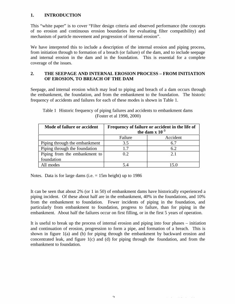
1. INTRODUCTION
This “white paper” is to cover “Filter design criteria and observed performance (the concepts of no erosion and continuous erosion boundaries for evaluating filter compatibility) and mechanism of particle movement and progression of internal erosion”.
We have interpreted this to include a description of the internal erosion and piping process, from initiation through to formation of a breach (or failure) of the dam, and to include seepage and internal erosion in the dam and in the foundation. This is essential for a complete coverage of the issues.
2. THE SEEPAGE AND INTERNAL EROSION PROCESS – FROM INITIATION OF EROSION, TO BREACH OF THE DAM
Seepage, and internal erosion which may lead to piping and breach of a dam occurs through the embankment, the foundation, and from the embankment to the foundation. The historic frequency of accidents and failures for each of these modes is shown in Table 1.
Table 1 Historic frequency of piping failures and accidents to embankment dams (Foster et al 1998, 2000)
Mode of failure or accident Frequency of failure or accident in the life of the dam x 10-3
Failure Accident Piping through the embankment 3.5 6.7 Piping through the foundation 1.7 6.2 Piping from the embankment to foundation
0.2 2.1
All modes 5.4 15.0
Notes. Data is for large dams (i.e. = 15m height) up to 1986
It can be seen that about 2% (or 1 in 50) of embankment dams have historically experienced a piping incident. Of these about half are in the embankment, 40% in the foundations, and 10% from the embankment to foundation. Fewer incidents of piping in the foundation, and particularly from embankment to foundation, progress to failure, than for piping in the embankment. About half the failures occur on first filling, or in the first 5 years of operation.
It is useful to break up the process of internal erosion and piping into four phases – initiation and continuation of erosion, progression to form a pipe, and formation of a breach. This is shown in figure 1(a) and (b) for piping through the embankment by backward erosion and concentrated leak, and figure 1(c) and (d) for piping through the foundation, and from the embankment to foundation.
2 Attachment 5 White Paper 2.doc
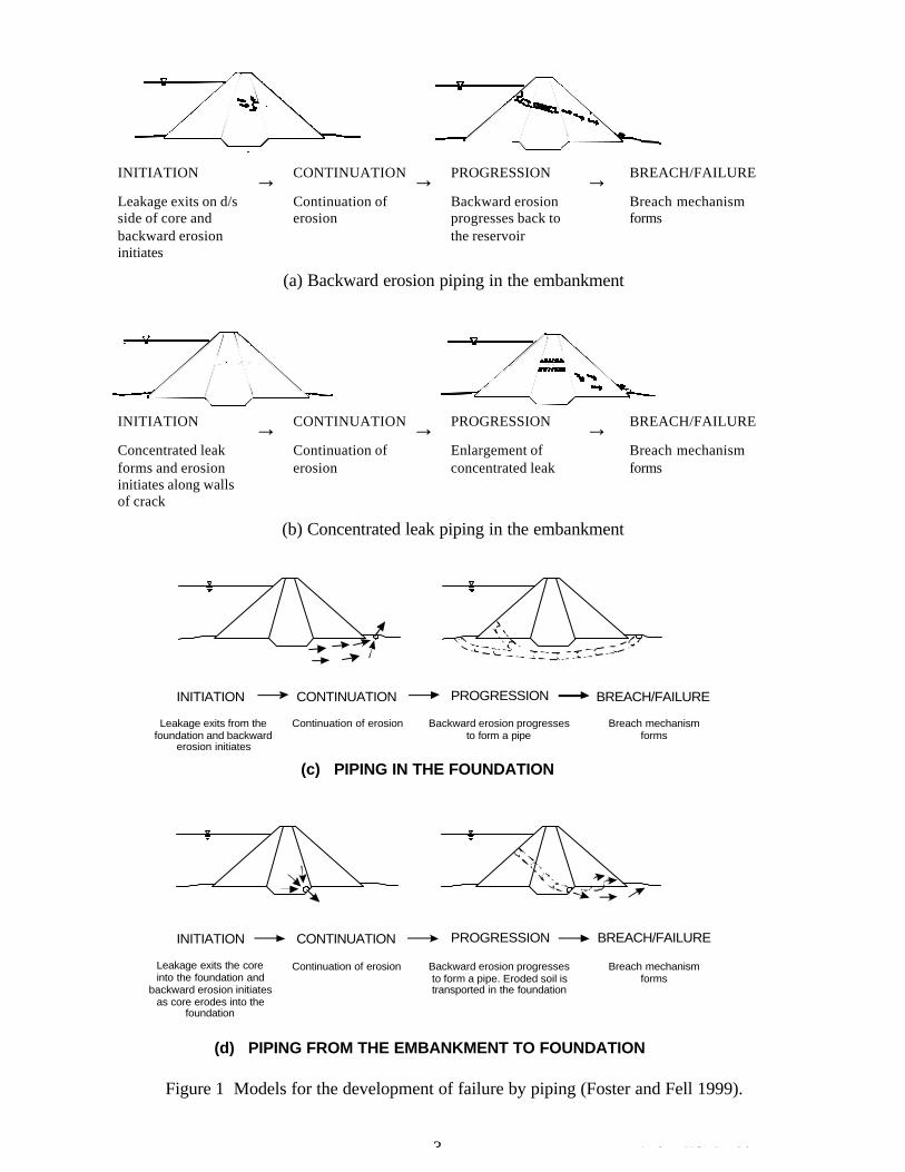
INITIATION CONTINUATION fi PROGRESSION BREACH/FAILUREfi fi Leakage exits on d/s Continuation of side of core and erosion backward erosion initiates
Backward erosion Breach mechanism progresses back to forms the reservoir
(a) Backward erosion piping in the embankment
INITIATION CONTINUATION fi PROGRESSION BREACH/FAILUREfi fi Concentrated leak Continuation of Enlargement of Breach mechanism forms and erosion erosion concentrated leak forms initiates along walls of crack
(b) Concentrated leak piping in the embankment
INITIATION CONTINUATION PROGRESSION BREACH/FAILURE
Leakage exits from the Continuation of erosion Backward erosion progresses Breach mechanism foundation and backward to form a pipe forms
erosion initiates
(c) PIPING IN THE FOUNDATION
INITIATION CONTINUATION PROGRESSION BREACH/FAILURE
Leakage exits the core Continuation of erosion Backward erosion progresses Breach mechanism into the foundation and to form a pipe. Eroded soil is forms
backward erosion initiates transported in the foundation as core erodes into the
foundation
(d) PIPING FROM THE EMBANKMENT TO FOUNDATION
Figure 1 Models for the development of failure by piping (Foster and Fell 1999).
3 Attachment 5 White Paper 2.doc
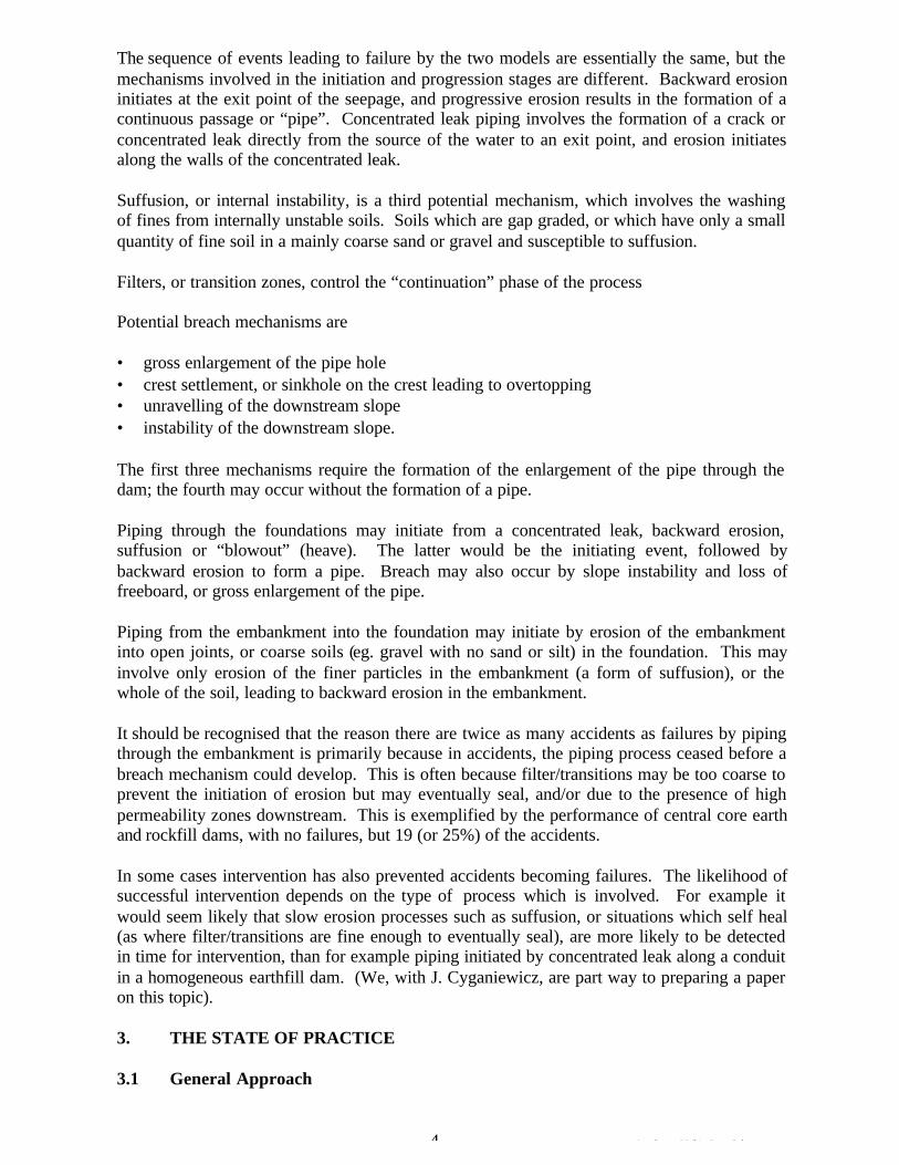
The sequence of events leading to failure by the two models are essentially the same, but the mechanisms involved in the initiation and progression stages are different. Backward erosion initiates at the exit point of the seepage, and progressive erosion results in the formation of a continuous passage or “pipe”. Concentrated leak piping involves the formation of a crack or concentrated leak directly from the source of the water to an exit point, and erosion initiates along the walls of the concentrated leak.
Suffusion, or internal instability, is a third potential mechanism, which involves the washing of fines from internally unstable soils. Soils which are gap graded, or which have only a small quantity of fine soil in a mainly coarse sand or gravel and susceptible to suffusion.
Filters, or transition zones, control the “continuation” phase of the process
Potential breach mechanisms are
• gross enlargement of the pipe hole • crest settlement, or sinkhole on the crest leading to overtopping • unravelling of the downstream slope • instability of the downstream slope.
The first three mechanisms require the formation of the enlargement of the pipe through the dam; the fourth may occur without the formation of a pipe.
Piping through the foundations may initiate from a concentrated leak, backward erosion, suffusion or “blowout” (heave). The latter would be the initiating event, followed by backward erosion to form a pipe. Breach may also occur by slope instability and loss of freeboard, or gross enlargement of the pipe.
Piping from the embankment into the foundation may initiate by erosion of the embankment into open joints, or coarse soils (eg. gravel with no sand or silt) in the foundation. This may involve only erosion of the finer particles in the embankment (a form of suffusion), or the whole of the soil, leading to backward erosion in the embankment.
It should be recognised that the reason there are twice as many accidents as failures by piping through the embankment is primarily because in accidents, the piping process ceased before a breach mechanism could develop. This is often because filter/transitions may be too coarse to prevent the initiation of erosion but may eventually seal, and/or due to the presence of high permeability zones downstream. This is exemplified by the performance of central core earth and rockfill dams, with no failures, but 19 (or 25%) of the accidents.
In some cases intervention has also prevented accidents becoming failures. The likelihood of successful intervention depends on the type of process which is involved. For example it would seem likely that slow erosion processes such as suffusion, or situations which self heal (as where filter/transitions are fine enough to eventually seal), are more likely to be detected in time for intervention, than for example piping initiated by concentrated leak along a conduit in a homogeneous earthfill dam. (We, with J. Cyganiewicz, are part way to preparing a paper on this topic).
3. THE STATE OF PRACTICE
3.1 General Approach
4 Attachment 5 White Paper 2.doc
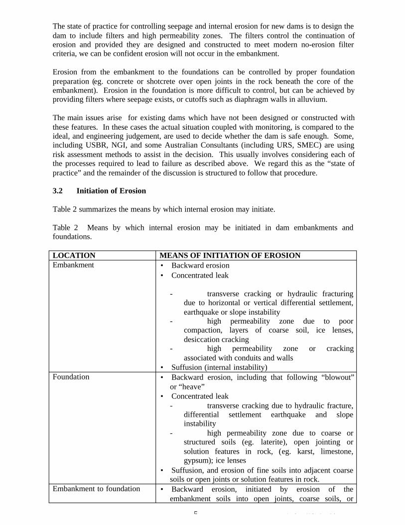
The state of practice for controlling seepage and internal erosion for new dams is to design the dam to include filters and high permeability zones. The filters control the continuation of erosion and provided they are designed and constructed to meet modern no-erosion filter criteria, we can be confident erosion will not occur in the embankment.
Erosion from the embankment to the foundations can be controlled by proper foundation preparation (eg. concrete or shotcrete over open joints in the rock beneath the core of the embankment). Erosion in the foundation is more difficult to control, but can be achieved by providing filters where seepage exists, or cutoffs such as diaphragm walls in alluvium.
The main issues arise for existing dams which have not been designed or constructed with these features. In these cases the actual situation coupled with monitoring, is compared to the ideal, and engineering judgement, are used to decide whether the dam is safe enough. Some, including USBR, NGI, and some Australian Consultants (including URS, SMEC) are using risk assessment methods to assist in the decision. This usually involves considering each of the processes required to lead to failure as described above. We regard this as the “state of practice” and the remainder of the discussion is structured to follow that procedure.
3.2 Initiation of Erosion
Table 2 summarizes the means by which internal erosion may initiate.
Table 2 Means by which internal erosion may be initiated in dam embankments and foundations.
LOCATION MEANS OF INITIATION OF EROSION Embankment • Backward erosion
• Concentrated leak
- transverse cracking or hydraulic fracturing due to horizontal or vertical differential settlement, earthquake or slope instability
- high permeability zone due to poor compaction, layers of coarse soil, ice lenses, desiccation cracking
- high permeability zone or cracking associated with conduits and walls
• Suffusion (internal instability) Foundation • Backward erosion, including that following “blowout”
or “heave” • Concentrated leak
- transverse cracking due to hydraulic fracture, differential settlement earthquake and slope instability
- high permeability zone due to coarse or structured soils (eg. laterite), open jointing or solution features in rock, (eg. karst, limestone, gypsum); ice lenses
• Suffusion, and erosion of fine soils into adjacent coarse soils or open joints or solution features in rock.
Embankment to foundation • Backward erosion, initiated by erosion of the embankment soils into open joints, coarse soils, or
5 Attachment 5 White Paper 2.doc
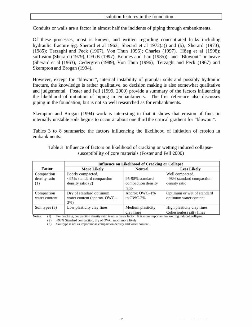
solution features in the foundation.
Conduits or walls are a factor in almost half the incidents of piping through embankments.
Of these processes, most is known, and written regarding concentrated leaks including hydraulic fracture (eg. Sherard et al 1963, Sherard et al 1972(a)) and (b), Sherard (1973), (1985); Terzaghi and Peck (1967), Von Thun 1996); Charles (1997), Höeg et al (1998); suffusion (Sherard (1979), CFGB (1997), Kenney and Lau (1985)); and “Blowout” or heave (Sherard et al (1963), Cedergren (1989), Von Thun (1996), Terzaghi and Peck (1967) and Skempton and Brogan (1994).
However, except for “blowout”, internal instability of granular soils and possibly hydraulic fracture, the knowledge is rather qualitative, so decision making is also somewhat qualitative and judgemental. Foster and Fell (1999, 2000) provide a summary of the factors influencing the likelihood of initiation of piping in embankments. The first reference also discusses piping in the foundation, but is not so well researched as for embankments.
Skempton and Brogan (1994) work is interesting in that it shows that erosion of fines in internally unstable soils begins to occur at about one third the critical gradient for “blowout”.
Tables 3 to 8 summarize the factors influencing the likelihood of initiation of erosion in embankments.
Table 3 Influence of factors on likelihood of cracking or wetting induced collapse-susceptibility of core materials (Foster and Fell 2000)
Factor Influence on Likelihood of Cracking or Collapse
More Likely Neutral Less Likely Compaction Poorly compacted, Well compacted, density ratio <95% standard compaction 95-98% standard =98% standard compaction (1) density ratio (2) compaction density density ratio
ratio Compaction Dry of standard optimum Approx OWC–1% Optimum or wet of standard water content water content (approx. OWC – to OWC-2% optimum water content
3%) Soil types (3) Low plasticity clay fines Medium plasticity High plasticity clay fines
clay fines Cohesionless silty fines Notes: (1) For cracking, compaction density ratio is not a major factor. It is more important for wetting induced collapse.
(2) <93% Standard compaction, dry of OWC, much more likely. (3) Soil type is not as important as compaction density and water content.
6 Attachment 5 White Paper 2.doc
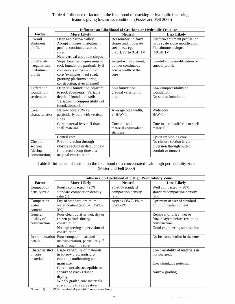
Table 4 Influence of factors in the likelihood of cracking or hydraulic fracturing – features giving low stress conditions (Foster and Fell 2000)
Factor Influence on Likelihood of Cracking or Hydraulic Fracture
More Likely Neutral Less Likely Overall Deep and narrow valley. Reasonably uniform Uniform abutment profile, or abutment Abrupt changes in abutment slopes and moderate large scale slope modification. profile profile, continuous across steepness, eg. Flat abutment slopes
core. 0.25H:1V to 0.5H:1V (>0.5H:1V) Near vertical abutment slopes
Small scale Steps, benches, depressions in Irregularities present, Careful slope modification or irregularities rock foundation, particularly if but not continuous smooth profile in abutment continuous across width of across width of the profile core (examples: haul road, core
grouting platforms during construction, river channel)
Differential foundation settlement
Deep soil foundation adjacent to rock abutments. Variable depth of foundation soils.
Soil foundation, gradual variation in depth
Low compressibility soil foundation. No soil in foundation
Variation in compressibility of foundation soils
Core Narrow core, H/W>2, Average core width, Wide core characteristics particularly core with vertical 2<H/W<1 H/W<1
sides Core material less stiff than Core and shell Core material stiffer than shell shell material materials equivalent material
stiffness Central core Upstream sloping core
Closure River diversion through No closure section (river section closure section in dam, or new diversion through outlet (during fill placed a long time after conduit or tunnel) construction) original construction
Table 5 Influence of factors on the likelihood of a concentrated leak –high permeability zone (Foster and Fell 2000)
Factor Influence on Likelihood of a High Permeability Zone
More Likely Neutral Less Likely Compaction Poorly compacted, <95% 95-98% standard Well compacted, = 98% density ratio standard compaction density compaction density standard compaction density
ratio (1) ratio ratio Compaction Dry of standard optimum Approx OWC-1% to Optimum or wet of standard water water content (approx. OWC- OWC-2% optimum water content content 3%) General quality of construction
Poor clean up after wet, dry or frozen periods during construction.
Removal of dried, wet or frozen layers before resuming construction
No engineering supervision of construction
Good engineering supervision
Instrumentation Poor compaction around No instrumentation in the core details instrumentation, particularly if
pass through the core Characteristics of core
Large variability of materials in borrow area, moisture
Low variability of materials in borrow areas
materials content, conditioning and grain size. Core materials susceptible to shrinkage cracks due to
Low shrinkage potential.
Narrow grading drying. Widely graded core materials susceptible to segregation
Notes: (1) <93% Standard, dry of OWC, much more likely.
7 Attachment 5 White Paper 2.doc
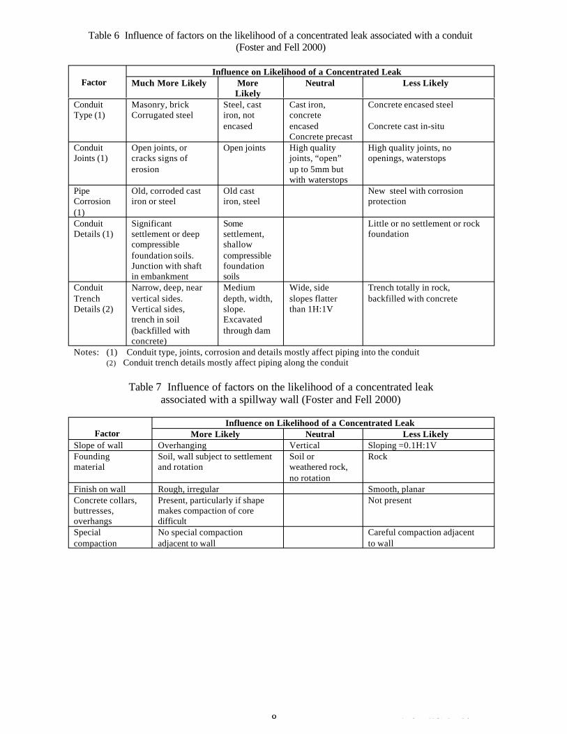
Table 6 Influence of factors on the likelihood of a concentrated leak associated with a conduit (Foster and Fell 2000)
Factor Influence on Likelihood of a Concentrated Leak
Much More Likely More Likely
Neutral Less Likely
Conduit Masonry, brick Steel, cast Cast iron, Concrete encased steel Type (1) Corrugated steel iron, not concrete
encased encased Concrete cast in-situ Concrete precast
Conduit Open joints, or Open joints High quality High quality joints, no Joints (1) cracks signs of joints, “open” openings, waterstops
erosion up to 5mm but with waterstops
Pipe Old, corroded cast Old cast New steel with corrosion Corrosion iron or steel iron, steel protection (1) Conduit Details (1)
Significant settlement or deep compressible
Some settlement, shallow
Little or no settlement or rock foundation
foundation soils. Junction with shaft
compressible foundation
in embankment soils Conduit Narrow, deep, near Medium Wide, side Trench totally in rock, Trench Details (2)
vertical sides. Vertical sides, trench in soil
depth, width, slope. Excavated
slopes flatter than 1H:1V
backfilled with concrete
(backfilled with concrete)
through dam
Notes: (1) Conduit type, joints, corrosion and details mostly affect piping into the conduit (2) Conduit trench details mostly affect piping along the conduit
Table 7 Influence of factors on the likelihood of a concentrated leak associated with a spillway wall (Foster and Fell 2000)
Factor Influence on Likelihood of a Concentrated Leak
More Likely Neutral Less Likely Slope of wall Overhanging Vertical Sloping =0.1H:1V Founding Soil, wall subject to settlement Soil or Rock material and rotation weathered rock,
no rotation Finish on wall Rough, irregular Smooth, planar Concrete collars, Present, particularly if shape Not present buttresses, makes compaction of core overhangs difficult Special No special compaction Careful compaction adjacent compaction adjacent to wall to wall
8 Attachment 5 White Paper 2.doc
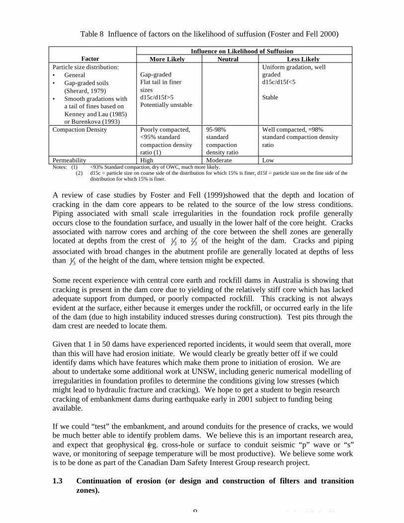
Table 8 Influence of factors on the likelihood of suffusion (Foster and Fell 2000)
Factor Influence on Likelihood of Suffusion
More Likely Neutral Less Likely Particle size distribution: • General • Gap-graded soils
(Sherard, 1979) • Smooth gradations with
a tail of fines based on Kenney and Lau (1985) or Burenkova (1993)
Gap-graded Flat tail in finer sizes d15c/d15f>5 Potentially unstable
Uniform gradation, well graded d15c/d15f<5
Stable
Compaction Density Poorly compacted, <95% standard
95-98% standard
Well compacted, =98% standard compaction density
compaction density ratio (1)
compaction density ratio
ratio
Permeability High Moderate Low Notes: (1) <93% Standard compaction, dry of OWC, much more likely.
(2) d15c = particle size on coarse side of the distribution for which 15% is finer, d15f = particle size on the fine side of the distribution for which 15% is finer.
A review of case studies by Foster and Fell (1999)showed that the depth and location of cracking in the dam core appears to be related to the source of the low stress conditions. Piping associated with small scale irregularities in the foundation rock profile generally occurs close to the foundation surface, and usually in the lower half of the core height. Cracks associated with narrow cores and arching of the core between the shell zones are generally located at depths from the crest of 3
1 to 32 of the height of the dam. Cracks and piping
associated with broad changes in the abutment profile are generally located at depths of less than 3
1 of the height of the dam, where tension might be expected.
Some recent experience with central core earth and rockfill dams in Australia is showing that cracking is present in the dam core due to yielding of the relatively stiff core which has lacked adequate support from dumped, or poorly compacted rockfill. This cracking is not always evident at the surface, either because it emerges under the rockfill, or occurred early in the life of the dam (due to high instability induced stresses during construction). Test pits through the dam crest are needed to locate them.
Given that 1 in 50 dams have experienced reported incidents, it would seem that overall, more than this will have had erosion initiate. We would clearly be greatly better off if we could identify dams which have features which make them prone to initiation of erosion. We are about to undertake some additional work at UNSW, including generic numerical modelling of irregularities in foundation profiles to determine the conditions giving low stresses (which might lead to hydraulic fracture and cracking). We hope to get a student to begin research cracking of embankment dams during earthquake early in 2001 subject to funding being available.
If we could “test” the embankment, and around conduits for the presence of cracks, we would be much better able to identify problem dams. We believe this is an important research area, and expect that geophysical (eg. cross-hole or surface to conduit seismic “p” wave or “s” wave, or monitoring of seepage temperature will be most productive). We believe some work is to be done as part of the Canadian Dam Safety Interest Group research project.
1.3 Continuation of erosion (or design and construction of filters and transition zones).
9 Attachment 5 White Paper 2.doc
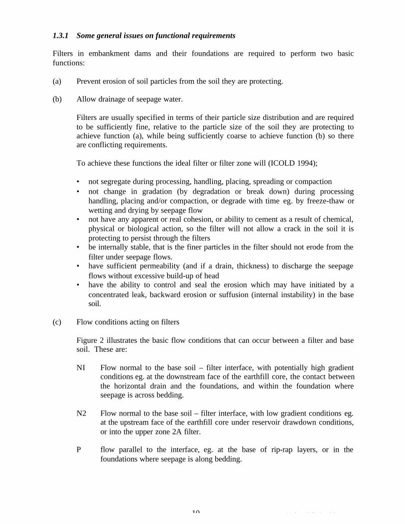
1.3.1 Some general issues on functional requirements
Filters in embankment dams and their foundations are required to perform two basic functions:
(a) Prevent erosion of soil particles from the soil they are protecting.
(b) Allow drainage of seepage water.
Filters are usually specified in terms of their particle size distribution and are required to be sufficiently fine, relative to the particle size of the soil they are protecting to achieve function (a), while being sufficiently coarse to achieve function (b) so there are conflicting requirements.
To achieve these functions the ideal filter or filter zone will (ICOLD 1994);
• not segregate during processing, handling, placing, spreading or compaction • not change in gradation (by degradation or break down) during processing
handling, placing and/or compaction, or degrade with time eg. by freeze-thaw or wetting and drying by seepage flow
• not have any apparent or real cohesion, or ability to cement as a result of chemical, physical or biological action, so the filter will not allow a crack in the soil it is protecting to persist through the filters
• be internally stable, that is the finer particles in the filter should not erode from the filter under seepage flows.
• have sufficient permeability (and if a drain, thickness) to discharge the seepage flows without excessive build-up of head
• have the ability to control and seal the erosion which may have initiated by a concentrated leak, backward erosion or suffusion (internal instability) in the base soil.
(c) Flow conditions acting on filters
Figure 2 illustrates the basic flow conditions that can occur between a filter and base soil. These are:
NI Flow normal to the base soil – filter interface, with potentially high gradient conditions eg. at the downstream face of the earthfill core, the contact between the horizontal drain and the foundations, and within the foundation where seepage is across bedding.
N2 Flow normal to the base soil – filter interface, with low gradient conditions eg. at the upstream face of the earthfill core under reservoir drawdown conditions, or into the upper zone 2A filter.
P flow parallel to the interface, eg. at the base of rip-rap layers, or in the foundations where seepage is along bedding.
10 Attachment 5 White Paper 2.doc
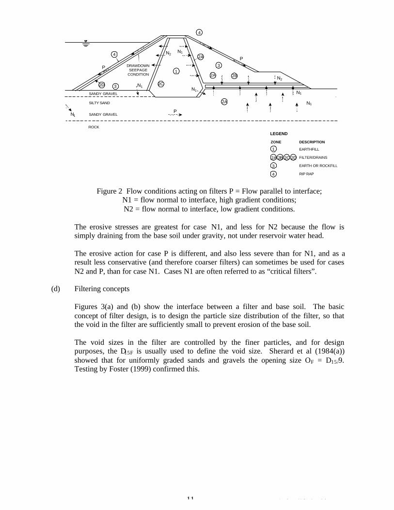
4
2D 3
1
2C
4
2A
3
2A
2A
2B
P
P
P
N1
N1
N1N2
N1
N2
N1
N1
DRAWDOWN SEEPAGE
CONDITION
SANDY GRAVEL
SILTY SAND
SANDY GRAVEL
ROCK
LEGEND
ZONE DESCRIPTION
1 EARTHFILL
FILTER/DRAINS
EARTH OR ROCKFILL
RIP RAP
2A 2B 2C 2D
3
4
Figure 2 Flow conditions acting on filters P = Flow parallel to interface; N1 = flow normal to interface, high gradient conditions; N2 = flow normal to interface, low gradient conditions.
The erosive stresses are greatest for case N1, and less for N2 because the flow is simply draining from the base soil under gravity, not under reservoir water head.
The erosive action for case P is different, and also less severe than for N1, and as a result less conservative (and therefore coarser filters) can sometimes be used for cases N2 and P, than for case N1. Cases N1 are often referred to as “critical filters”.
(d) Filtering concepts
Figures 3(a) and (b) show the interface between a filter and base soil. The basic concept of filter design, is to design the particle size distribution of the filter, so that the void in the filter are sufficiently small to prevent erosion of the base soil.
The void sizes in the filter are controlled by the finer particles, and for design purposes, the D15F is usually used to define the void size. Sherard et al (1984(a)) showed that for uniformly graded sands and gravels the opening size OF = D15/9. Testing by Foster (1999) confirmed this.
11 Attachment 5 White Paper 2.doc
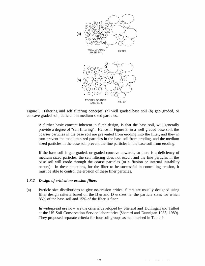
12 Attachment 5 White Paper 2.doc
Figure 3 Filtering and self filtering concepts, (a) well graded base soil (b) gap graded, orconcave graded soil, deficient in medium sized particles.
A further basic concept inherent in filter design, is that the base soil, will generallyprovide a degree of “self filtering”. Hence in Figure 3, in a well graded base soil, thecoarser particles in the base soil are prevented from eroding into the filter, and they inturn prevent the medium sized particles in the base soil from eroding, and the mediumsized particles in the base soil prevent the fine particles in the base soil from eroding.
If the base soil is gap graded, or graded concave upwards, so there is a deficiency ofmedium sized particles, the self filtering does not occur, and the fine particles in thebase soil will erode through the coarse particles (or suffusion or internal instabilityoccurs). In these situations, for the filter to be successful in controlling erosion, itmust be able to control the erosion of these finer particles.
1.3.2 Design of critical no-erosion filters
(a) Particle size distributions to give no-erosion critical filters are usually designed usingfilter design criteria based on the D85B and D15F sizes ie. the particle sizes for which85% of the base soil and 15% of the filter is finer.
In widespread use now are the criteria developed by Sherard and Dunnigan and Talbotat the US Soil Conservation Service laboratories (Sherard and Dunnigan 1985, 1989).They proposed separate criteria for four soil groups as summarised in Table 9.
WELL GRADED BASE SOIL
POORLY GRADED BASE SOIL
FILTER
FILTER
(a)
(b)
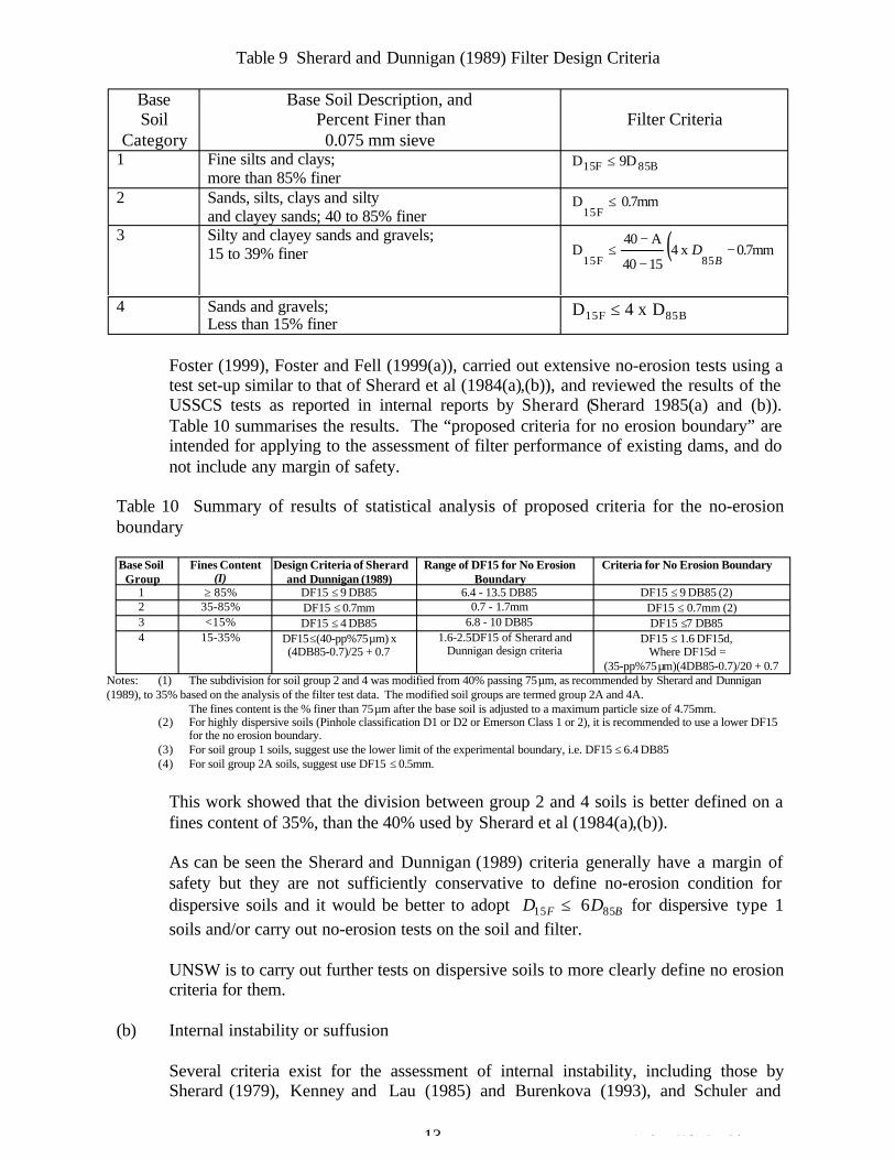
Table 9 Sherard and Dunnigan (1989) Filter Design Criteria
C
Base Soil
ategory
Base Soil Description, and Percent Finer than 0.075 mm sieve
Filter Criteria
1 Fine silts and clays; more than 85% finer
F15 D B85 D9 £
2 Sands, silts, clays and silty and clayey sands; 40 to 85% finer
D 15F
0.7mm£
3 Silty and clayey sands and gravels; 15 to 39% finer D
15F ( )0.7mmx 4
1540
A40 85
--
-£
B D
4 Sands and gravels; Less than 15% finer 15FD 85BD x 4 £
Foster (1999), Foster and Fell (1999(a)), carried out extensive no-erosion tests using a test set-up similar to that of Sherard et al (1984(a),(b)), and reviewed the results of the USSCS tests as reported in internal reports by Sherard (Sherard 1985(a) and (b)). Table 10 summarises the results. The “proposed criteria for no erosion boundary” are intended for applying to the assessment of filter performance of existing dams, and do not include any margin of safety.
Table 10 Summary of results of statistical analysis of proposed criteria for the no-erosion boundary
Base Soil Fines Content Design Criteria of Sherard Range of DF15 for No Erosion Criteria for No Erosion Boundary Group (I) and Dunnigan (1989) Boundary
1 ‡ 85% DF15 £ 9 DB85 6.4 - 13.5 DB85 DF15 £ 9 DB85 (2) 2 35-85% DF15 £ 0.7mm 0.7 - 1.7mm DF15 £ 0.7mm (2) 3 <15% DF15 £ 4 DB85 6.8 - 10 DB85 DF15 £7 DB85 4 15-35% DF15£(40-pp%75mm) x 1.6-2.5DF15 of Sherard and DF15 £ 1.6 DF15d,
(4DB85-0.7)/25 + 0.7 Dunnigan design criteria Where DF15d = (35-pp%75 mm)(4DB85-0.7)/20 + 0.7
Notes: (1) The subdivision for soil group 2 and 4 was modified from 40% passing 75 mm, as recommended by Sherard and Dunnigan (1989), to 35% based on the analysis of the filter test data. The modified soil groups are termed group 2A and 4A.
The fines content is the % finer than 75 mm after the base soil is adjusted to a maximum particle size of 4.75mm. (2) For highly dispersive soils (Pinhole classification D1 or D2 or Emerson Class 1 or 2), it is recommended to use a lower DF15
for the no erosion boundary. (3) For soil group 1 soils, suggest use the lower limit of the experimental boundary, i.e. DF15 £ 6.4 DB85 (4) For soil group 2A soils, suggest use DF15 £ 0.5mm.
This work showed that the division between group 2 and 4 soils is better defined on a fines content of 35%, than the 40% used by Sherard et al (1984(a),(b)).
As can be seen the Sherard and Dunnigan (1989) criteria generally have a margin of safety but they are not sufficiently conservative to define no-erosion condition for dispersive soils and it would be better to adopt D15F £ 6D85B for dispersive type 1 soils and/or carry out no-erosion tests on the soil and filter.
UNSW is to carry out further tests on dispersive soils to more clearly define no erosion criteria for them.
(b) Internal instability or suffusion
Several criteria exist for the assessment of internal instability, including those by Sherard (1979), Kenney and Lau (1985) and Burenkova (1993), and Schuler and
13 Attachment 5 White Paper 2.doc
Brauns (1993). It should be noted that these criteria only apply to granular soils. There are no criteria for cohesive soils eg. gravelly clays. For design purposes the Sherard and Dunnigan (1989) method requires “regrading” of these soils to that passing the 4.75 mm sieve to overcome the problem. UNSW are planning to carry out tests on cohesive soils, probably placed as a slurry, to see if criteria can be established.
(c) Segregation
Characteristics which make sand-gravel filter segregate on placement include
(a) a broad grading, particularly with maximum particle size > 75mm (b) a low percentage of sand and fine gravel sizes (< 40% finer than 4.75mm) (c) poor construction practices eg. end-dumping from trucks, high lift heights, and
poor control of stockpiling operations.
Sherard and Dunnigan (1989) suggested using filters with a maximum size not greater than 50 mm, and required no less than 40% sand and fine gravel. Ripley (1986) recommended for filters in contact with the core:
• maximum size 19 mm • > 60% finer than 4.75 mm • < 2% finer than 0.075 mm
These criteria were based on construction experience.
Kenney and Westland (1993) carried out laboratory tests and concluded that:
• all dry soils consisting of sands and gravels segregate in the same general way, independent of grain size and grain size distributions
• dry soils containing fines <0.075 mm, segregate to a smaller extend than soils not containing fines
• water in sandy soils with a mean size finer than 3mm to 4 mm, inhibits segregation but has little influence on the segregation of gravels (mean size coarser than 10 mm to 12 mm).
The USDA – SCS (1994) and USBR (1987) have adopted a maximum size of 75 mm, and limits on the minimum D10F and maximum D90F to limit segregation. The authors believe that for narrow or thin filter zones, this may be too large, and recommend the use of maximum size of 37 mm or 50 mm in these situations.
(d) Filter permeability and ability to hold a crack
The filter must be sufficiently permeable that the seepage flow can pass through it without significant build up of pressure. This has been taken account of by using the criteria D15F/D15B > 4 or 5; this ensures that the permeability of the filter is 15-20 times that of the soil.
However just as important is to keep the fines content (silt and clay sized particles) to a minimum.
14 Attachment 5 White Paper 2.doc
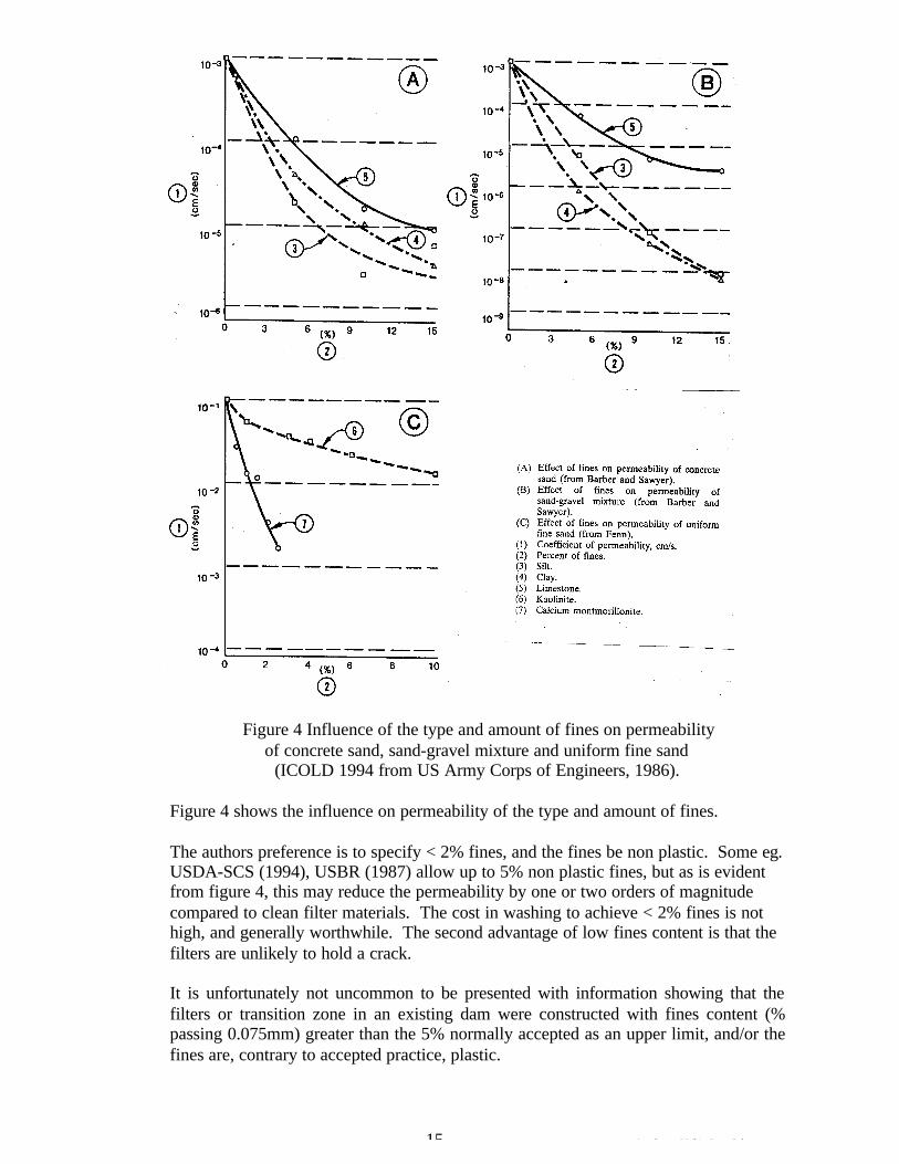
Figure 4 Influence of the type and amount of fines on permeability of concrete sand, sand-gravel mixture and uniform fine sand
(ICOLD 1994 from US Army Corps of Engineers, 1986).
Figure 4 shows the influence on permeability of the type and amount of fines.
The authors preference is to specify < 2% fines, and the fines be non plastic. Some eg. USDA-SCS (1994), USBR (1987) allow up to 5% non plastic fines, but as is evident from figure 4, this may reduce the permeability by one or two orders of magnitude compared to clean filter materials. The cost in washing to achieve < 2% fines is not high, and generally worthwhile. The second advantage of low fines content is that the filters are unlikely to hold a crack.
It is unfortunately not uncommon to be presented with information showing that the filters or transition zone in an existing dam were constructed with fines content (% passing 0.075mm) greater than the 5% normally accepted as an upper limit, and/or the fines are, contrary to accepted practice, plastic.
15 Attachment 5 White Paper 2.doc
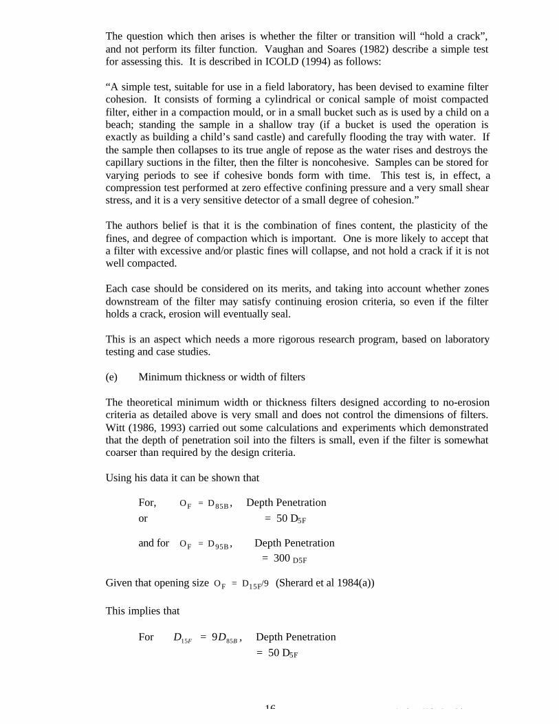
The question which then arises is whether the filter or transition will “hold a crack”, and not perform its filter function. Vaughan and Soares (1982) describe a simple test for assessing this. It is described in ICOLD (1994) as follows:
“A simple test, suitable for use in a field laboratory, has been devised to examine filter cohesion. It consists of forming a cylindrical or conical sample of moist compacted filter, either in a compaction mould, or in a small bucket such as is used by a child on a beach; standing the sample in a shallow tray (if a bucket is used the operation is exactly as building a child’s sand castle) and carefully flooding the tray with water. If the sample then collapses to its true angle of repose as the water rises and destroys the capillary suctions in the filter, then the filter is noncohesive. Samples can be stored for varying periods to see if cohesive bonds form with time. This test is, in effect, a compression test performed at zero effective confining pressure and a very small shear stress, and it is a very sensitive detector of a small degree of cohesion.”
The authors belief is that it is the combination of fines content, the plasticity of the fines, and degree of compaction which is important. One is more likely to accept that a filter with excessive and/or plastic fines will collapse, and not hold a crack if it is not well compacted.
Each case should be considered on its merits, and taking into account whether zones downstream of the filter may satisfy continuing erosion criteria, so even if the filter holds a crack, erosion will eventually seal.
This is an aspect which needs a more rigorous research program, based on laboratory testing and case studies.
(e) Minimum thickness or width of filters
The theoretical minimum width or thickness filters designed according to no-erosion criteria as detailed above is very small and does not control the dimensions of filters. Witt (1986, 1993) carried out some calculations and experiments which demonstrated that the depth of penetration soil into the filters is small, even if the filter is somewhat coarser than required by the design criteria.
Using his data it can be shown that
For, FO 85BD= , Depth Penetration or = 50 D5F
and for FO 95BD= , Depth Penetration = 300 D5F
Given that opening size O F = D15F/9 (Sherard et al 1984(a))
This implies that
For D15F = 9D85B , Depth Penetration = 50 D5F
16 Attachment 5 White Paper 2.doc
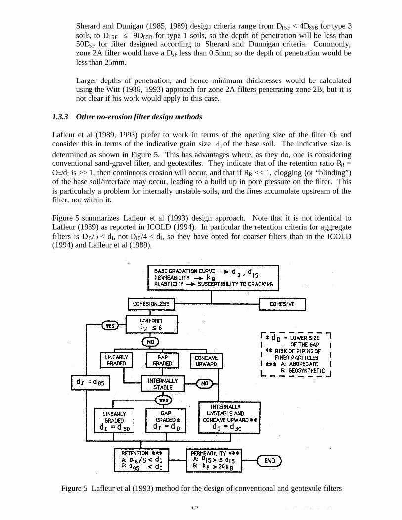
Sherard and Dunigan (1985, 1989) design criteria range from D15F < 4D85B for type 3 soils, to D15F £ 9D85B for type 1 soils, so the depth of penetration will be less than 50D5F for filter designed according to Sherard and Dunnigan criteria. Commonly, zone 2A filter would have a D5F less than 0.5mm, so the depth of penetration would be less than 25mm.
Larger depths of penetration, and hence minimum thicknesses would be calculated using the Witt (1986, 1993) approach for zone 2A filters penetrating zone 2B, but it is not clear if his work would apply to this case.
1.3.3 Other no-erosion filter design methods
Lafleur et al (1989, 1993) prefer to work in terms of the opening size of the filter OF and consider this in terms of the indicative grain size dI of the base soil. The indicative size is determined as shown in Figure 5. This has advantages where, as they do, one is considering conventional sand-gravel filter, and geotextiles. They indicate that of the retention ratio RR = OF/dI is >> 1, then continuous erosion will occur, and that if RR << 1, clogging (or “blinding”) of the base soil/interface may occur, leading to a build up in pore pressure on the filter. This is particularly a problem for internally unstable soils, and the fines accumulate upstream of the filter, not within it.
Figure 5 summarizes Lafleur et al (1993) design approach. Note that it is not identical to Lafleur (1989) as reported in ICOLD (1994). In particular the retention criteria for aggregate filters is D15/5 < dI, not D15/4 < dI, so they have opted for coarser filters than in the ICOLD (1994) and Lafleur et al (1989).
Figure 5 Lafleur et al (1993) method for the design of conventional and geotextile filters
17 Attachment 5 White Paper 2.doc
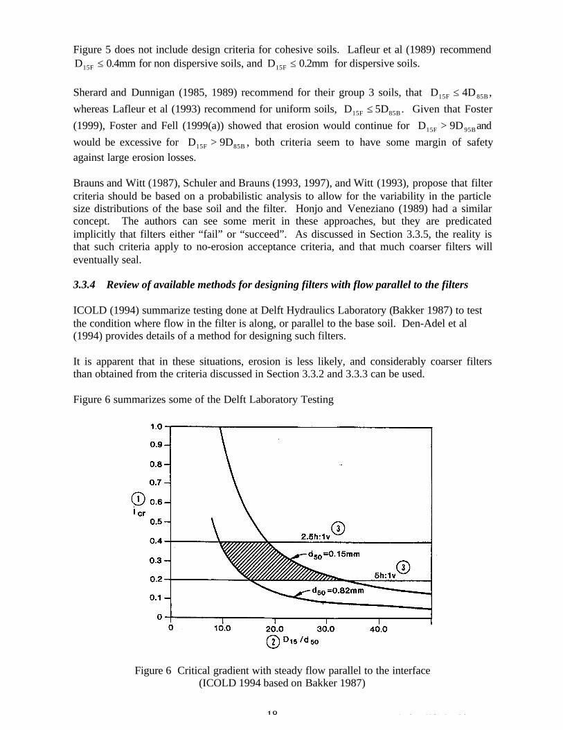
DFigure 5 does not include design criteria for cohesive soils. Lafleur et al (1989) recommend
15F £ 0.4mm for non dispersive soils, and D15F £ 0.2mm for dispersive soils.
Sherard and Dunnigan (1985, 1989) recommend for their group 3 soils, that D15F £ D4 85B , whereas Lafleur et al (1993) recommend for uniform soils, D15F £ D5 85B . Given that Foster (1999), Foster and Fell (1999(a)) showed that erosion would continue for D15F > D9 95Band would be excessive for D15F > D9 85B , both criteria seem to have some margin of safety against large erosion losses.
Brauns and Witt (1987), Schuler and Brauns (1993, 1997), and Witt (1993), propose that filter criteria should be based on a probabilistic analysis to allow for the variability in the particle size distributions of the base soil and the filter. Honjo and Veneziano (1989) had a similar concept. The authors can see some merit in these approaches, but they are predicated implicitly that filters either “fail” or “succeed”. As discussed in Section 3.3.5, the reality is that such criteria apply to no-erosion acceptance criteria, and that much coarser filters will eventually seal.
3.3.4 Review of available methods for designing filters with flow parallel to the filters
ICOLD (1994) summarize testing done at Delft Hydraulics Laboratory (Bakker 1987) to test the condition where flow in the filter is along, or parallel to the base soil. Den-Adel et al (1994) provides details of a method for designing such filters.
It is apparent that in these situations, erosion is less likely, and considerably coarser filters than obtained from the criteria discussed in Section 3.3.2 and 3.3.3 can be used.
Figure 6 summarizes some of the Delft Laboratory Testing
Figure 6 Critical gradient with steady flow parallel to the interface (ICOLD 1994 based on Bakker 1987)
18 Attachment 5 White Paper 2.doc
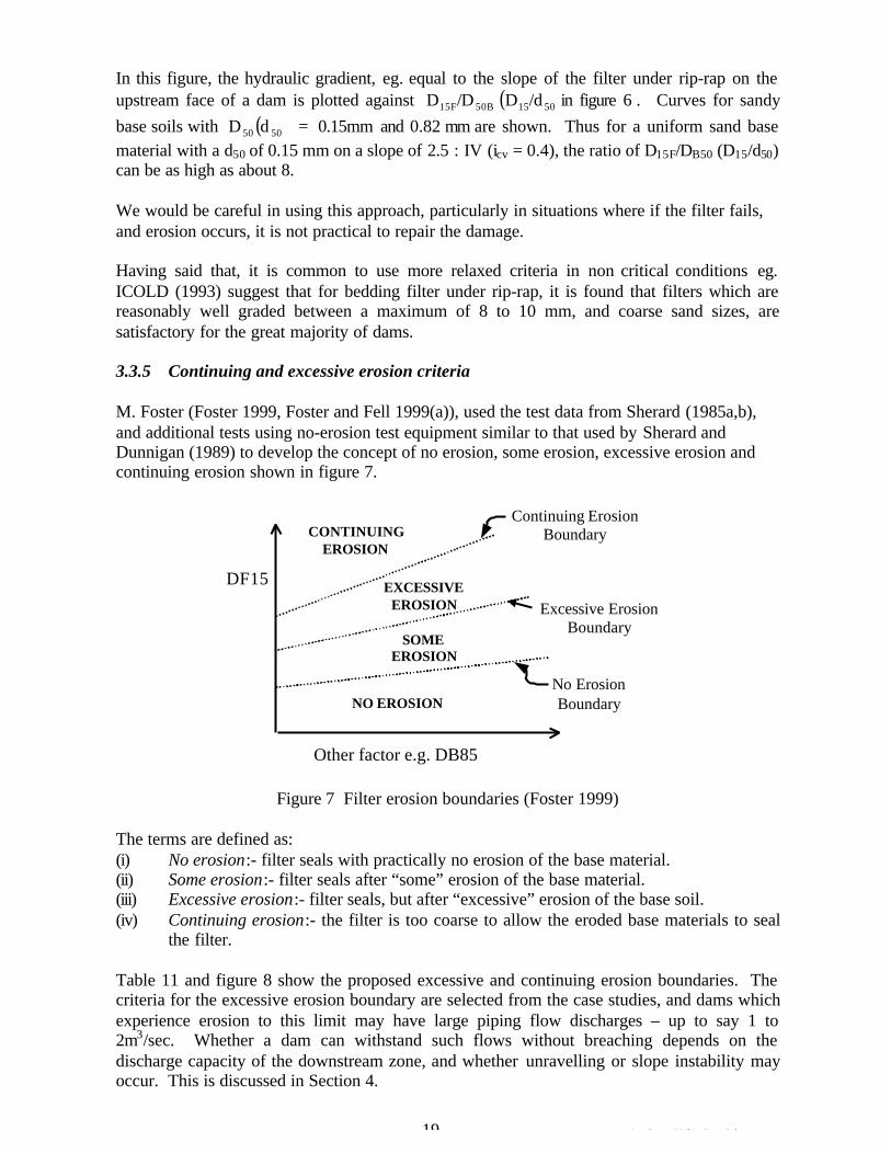
In this figure, the hydraulic gradient, eg. equal to the slope of the filter under rip-rap on the upstream face of a dam is plotted against D15F/D (D /d . 6 figure in ) Curves for sandy50B 15 50
base soils with D 50 (d ) = mm 0.82 and 0.15mm are shown. Thus for a uniform sand base50
material with a d50 of 0.15 mm on a slope of 2.5 : IV (icv = 0.4), the ratio of D15F/DB50 (D15/d50) can be as high as about 8.
We would be careful in using this approach, particularly in situations where if the filter fails, and erosion occurs, it is not practical to repair the damage.
Having said that, it is common to use more relaxed criteria in non critical conditions eg. ICOLD (1993) suggest that for bedding filter under rip-rap, it is found that filters which are reasonably well graded between a maximum of 8 to 10 mm, and coarse sand sizes, are satisfactory for the great majority of dams.
3.3.5 Continuing and excessive erosion criteria
M. Foster (Foster 1999, Foster and Fell 1999(a)), used the test data from Sherard (1985a,b), and additional tests using no-erosion test equipment similar to that used by Sherard and Dunnigan (1989) to develop the concept of no erosion, some erosion, excessive erosion and continuing erosion shown in figure 7.
CONTINUING EROSION
Continuing Erosion Boundary
No Erosion Boundary
SOME EROSION
NO EROSION
DF15
Excessive Erosion Boundary
EXCESSIVE EROSION
Other factor e.g. DB85
Figure 7 Filter erosion boundaries (Foster 1999)
The terms are defined as: (i) No erosion:- filter seals with practically no erosion of the base material. (ii) Some erosion:- filter seals after “some” erosion of the base material. (iii) Excessive erosion:- filter seals, but after “excessive” erosion of the base soil. (iv) Continuing erosion:- the filter is too coarse to allow the eroded base materials to seal
the filter.
Table 11 and figure 8 show the proposed excessive and continuing erosion boundaries. The criteria for the excessive erosion boundary are selected from the case studies, and dams which experience erosion to this limit may have large piping flow discharges – up to say 1 to 2m3/sec. Whether a dam can withstand such flows without breaching depends on the discharge capacity of the downstream zone, and whether unravelling or slope instability may occur. This is discussed in Section 4.
19 Attachment 5 White Paper 2.doc
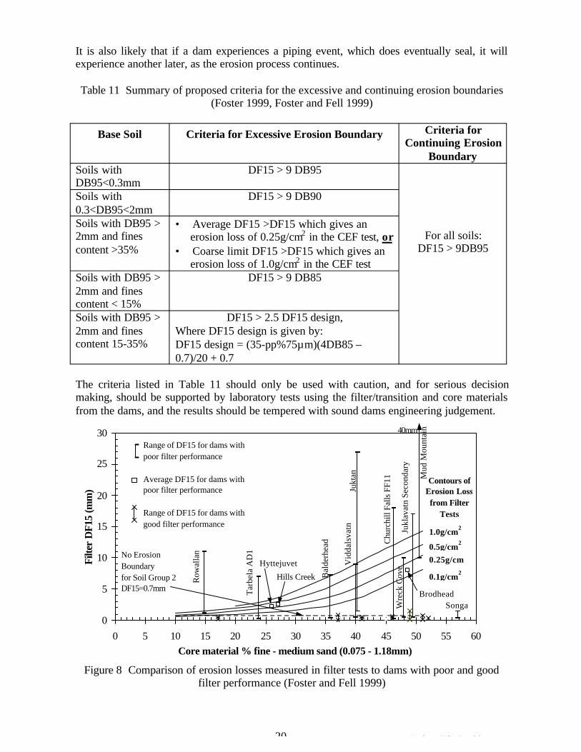
It is also likely that if a dam experiences a piping event, which does eventually seal, it will experience another later, as the erosion process continues.
Table 11 Summary of proposed criteria for the excessive and continuing erosion boundaries (Foster 1999, Foster and Fell 1999)
Base Soil Criteria for Excessive Erosion Boundary Criteria for Continuing Erosion
Boundary Soils with DF15 > 9 DB95 DB95<0.3mm Soils with DF15 > 9 DB90 0.3<DB95<2mm
For all soils: Soils with DB95 > 2mm and fines
• Average DF15 >DF15 which gives an erosion loss of 0.25g/cm2 in the CEF test, or
content >35% • Coarse limit DF15 >DF15 which gives an erosion loss of 1.0g/cm2 in the CEF test
DF15 > 9DB95
Soils with DB95 > DF15 > 9 DB85 2mm and fines content < 15% Soils with DB95 > 2mm and fines content 15-35%
DF15 > 2.5 DF15 design, Where DF15 design is given by: DF15 design = (35-pp%75mm)(4DB85 – 0.7)/20 + 0.7
The criteria listed in Table 11 should only be used with caution, and for serious decision making, should be supported by laboratory tests using the filter/transition and core materials from the dams, and the results should be tempered with sound dams engineering judgement.
Tar
bela
AD
1
Jukl
avat
n Se
cond
ary
Bal
derh
ead
Wre
ck C
ove
Chu
rchi
ll Fa
lls F
F11
Row
alla
n
Vid
dals
vatn
Ju
ktan
40mm M
ud M
ount
ain30
Range of DF15 for dams with poor filter performance
25 Average DF15 for dams with Contours of poor filter performance Erosion Loss
Filte
r D
F15
(mm
) 20 from Filter
Tests
1.0g/cm2
0.5g/cm2
0.25g/cm
Range of DF15 for dams with good filter performance15
No Erosion10 Boundary Hyttejuvet
2 0.1g/cm2Hills Creekfor Soil Group 2
DF15=0.7mm5 Brodhead Songa
0 0 5 10 15 20 25 30 35 40 45 50 55 60
Core material % fine - medium sand (0.075 - 1.18mm)
Figure 8 Comparison of erosion losses measured in filter tests to dams with poor and good filter performance (Foster and Fell 1999)
20 Attachment 5 White Paper 2.doc
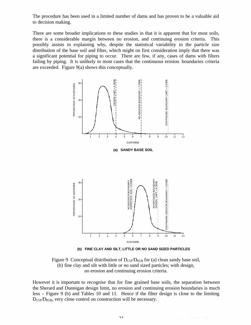
The procedure has been used in a limited number of dams and has proven to be a valuable aid to decision making.
There are some broader implications to these studies in that it is apparent that for most soils, there is a considerable margin between no erosion, and continuing erosion criteria. This possibly assists in explaining why, despite the statistical variability in the particle size distribution of the base soil and filter, which might on first consideration imply that there was a significant potential for piping to occur. There are few, if any, cases of dams with filters failing by piping. It is unlikely in most cases that the continuous erosion boundaries criteria are exceeded. Figure 9(a) shows this conceptually.
30
20
10PE
RC
EN
TAG
E O
F D
15F
/D85
B
B B B
DE
SIG
N L
I MIT
= 4
D8
5
NO
-ER
OS
ION
BO
UN
DA
RY
= 7
D85
CO
NTI
NU
ING
BO
UN
DA
RY
L IM
IT =
9 D
95
1 2 3 4 5 6 7 8 9 10 11 12
D15F/D85B
(a) SANDY BASE SOIL
30
20
10PE
RC
EN
TAG
E O
F D
15 F/
D85
B
II
II
I
NO
-ER
OS
O N
BO
UN
DA
RY
D
ISP
ER
SIV
E S
OL
= 6
D85
B
NO
-ER
OS
ON
BO
UN
DA
RY
D
ES
GN
LIM
IT =
9 D
8 5B
CO
NTI
NU
NG
ER
OS
ION
BO
UN
DA
RY
= 9
D95
B
1 2 3 4 5 6 7 8 9 10 11 12
D15F/D85B
(b) FINE CLAY AND SILT, LITTLE OR NO SAND SIZED PARTICLES
Figure 9 Conceptual distribution of D15F/D85B for (a) clean sandy base soil, (b) fine clay and silt with little or no sand sized particles; with design,
no erosion and continuing erosion criteria.
However it is important to recognise that for fine grained base soils, the separation between the Sherard and Dunnigan design limit, no erosion and continuing erosion boundaries is much less – Figure 9 (b) and Tables 10 and 11. Hence if the filter design is close to the limiting D15F/D85B, very close control on construction will be necessary.
21 Attachment 5 White Paper 2.doc
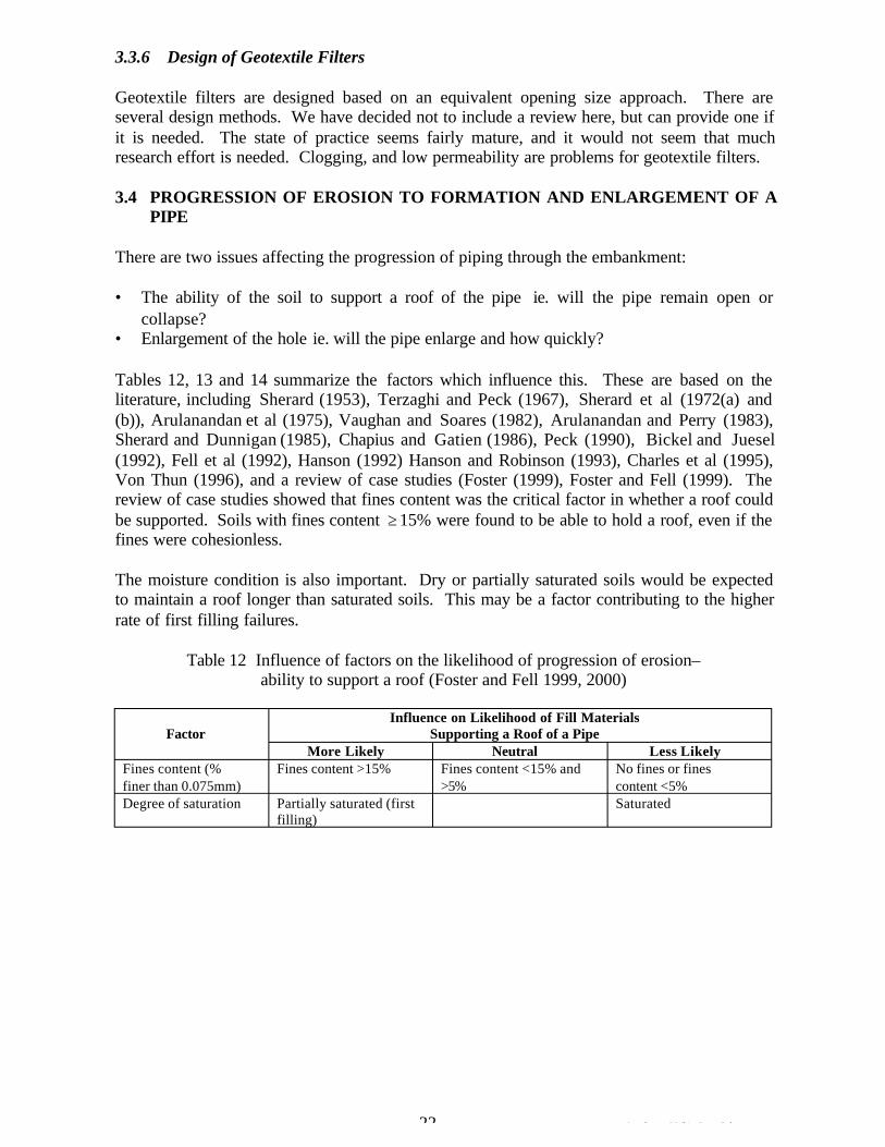
3.3.6 Design of Geotextile Filters
Geotextile filters are designed based on an equivalent opening size approach. There are several design methods. We have decided not to include a review here, but can provide one if it is needed. The state of practice seems fairly mature, and it would not seem that much research effort is needed. Clogging, and low permeability are problems for geotextile filters.
3.4 PROGRESSION OF EROSION TO FORMATION AND ENLARGEMENT OF A PIPE
There are two issues affecting the progression of piping through the embankment:
• The ability of the soil to support a roof of the pipe ie. will the pipe remain open or collapse?
• Enlargement of the hole ie. will the pipe enlarge and how quickly?
Tables 12, 13 and 14 summarize the factors which influence this. These are based on the literature, including Sherard (1953), Terzaghi and Peck (1967), Sherard et al (1972(a) and (b)), Arulanandan et al (1975), Vaughan and Soares (1982), Arulanandan and Perry (1983), Sherard and Dunnigan (1985), Chapius and Gatien (1986), Peck (1990), Bickel and Juesel (1992), Fell et al (1992), Hanson (1992) Hanson and Robinson (1993), Charles et al (1995), Von Thun (1996), and a review of case studies (Foster (1999), Foster and Fell (1999). The review of case studies showed that fines content was the critical factor in whether a roof could be supported. Soils with fines content ‡ 15% were found to be able to hold a roof, even if the fines were cohesionless.
The moisture condition is also important. Dry or partially saturated soils would be expected to maintain a roof longer than saturated soils. This may be a factor contributing to the higher rate of first filling failures.
Table 12 Influence of factors on the likelihood of progression of erosion– ability to support a roof (Foster and Fell 1999, 2000)
Factor Influence on Likelihood of Fill Materials
Supporting a Roof of a Pipe More Likely Neutral Less Likely
Fines content (% finer than 0.075mm)
Fines content >15% Fines content <15% and >5%
No fines or fines content <5%
Degree of saturation Partially saturated (first filling)
Saturated
22 Attachment 5 White Paper 2.doc
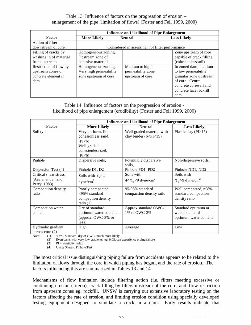
Table 13 Influence of factors on the progression of erosion – enlargement of the pipe (limitation of flows) (Foster and Fell 1999, 2000)
Factor Influence on Likelihood of Pipe Enlargement
More Likely Neutral Less Likely Action of filter downstream of core Considered in assessment of filter performance Filling of cracks by Homogeneous zoning. Zone upstream of core washing in of material Upstream zone of capable of crack filling from upstream cohesive material (cohesionless soil) Restriction of flow by upstream zones or
Homogeneous zoning. Very high permeability
Medium to high permeability zone
In zoned dam, medium to low permeability
concrete element in dam
zone upstream of core upstream of core granular zone upstream of core. Central concrete corewall and concrete face rockfill dam
Table 14 Influence of factors on the progression of erosion likelihood of pipe enlargement (erodibility) (Foster and Fell 1999, 2000)
Factor Influence on Likelihood of Pipe Enlargement
More Likely Neutral Less Likely Soil type Very uniform, fine
cohesionless sand. Well graded material with clay binder (6<PI<15)
Plastic clay (PI>15)
(PI<6) Well graded cohesionless soil. (PI<6)
Pinhole Dispersive soils, Potentially dispersive Non-dispersive soils, soils,
Dispersion Test (4) Pinhole D1, D2 Pinhole PD1, PD2 Pinhole ND1, ND2 Critical shear stress (Arulanandan and Perry, 1983)
Soils with ct <4
dyne/cm2
Soils with 4< ct <9 dyne/cm2
Soils with
ct >9 dyne/cm2
Compaction density Poorly compacted, 95-98% standard Well compacted, =98% ratio <95% standard compaction density ratio standard compaction
compaction density density ratio ratio (1)
Compaction water Dry of standard Approx standard OWC- Standard optimum or content optimum water content 1% to OWC-2% wet of standard
(approx. OWC-3% or optimum water content less)
Hydraulic gradient across core (2)
High Average Low
Note: (1) <93% Standard, dry of OWC, much more likely. (2) Even dams with very low gradients, eg. 0.05, can experience piping failure (3) PI = Plasticity index (4) Using Sherard Pinhole Test
The most critical issue distinguishing piping failure from accidents appears to be related to the limitation of flows through the core in which piping has begun, and the rate of erosion. The factors influencing this are summarized in Tables 13 and 14.
Mechanisms of flow limitation include filtering action (i.e. filters meeting excessive or continuing erosion criteria), crack filling by filters upstream of the core, and flow restriction from upstream zones eg. rockfill. UNSW is carrying out extensive laboratory testing on the factors affecting the rate of erosion, and limiting erosion condition using specially developed testing equipment designed to simulate a crack in a dam. Early results indicate that
23 Attachment 5 White Paper 2.doc
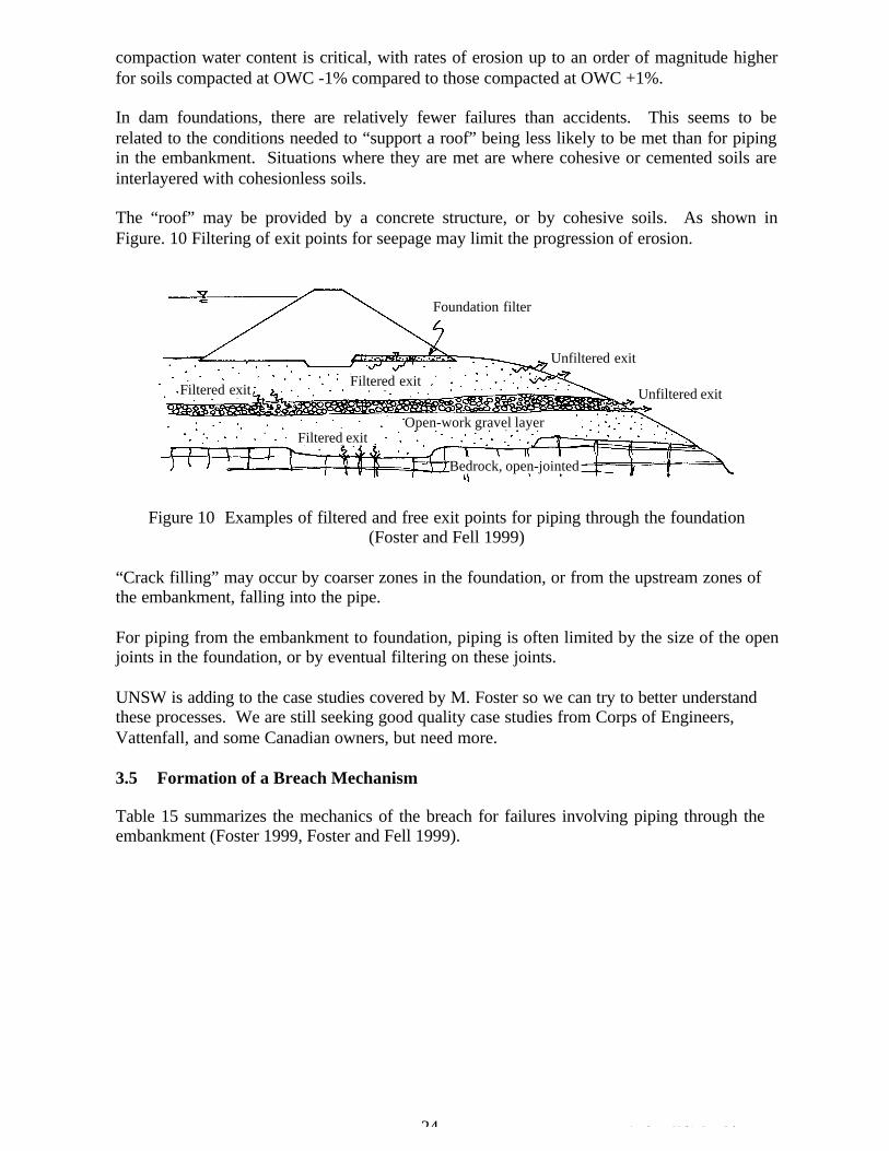
compaction water content is critical, with rates of erosion up to an order of magnitude higher for soils compacted at OWC -1% compared to those compacted at OWC +1%.
In dam foundations, there are relatively fewer failures than accidents. This seems to be related to the conditions needed to “support a roof” being less likely to be met than for piping in the embankment. Situations where they are met are where cohesive or cemented soils are interlayered with cohesionless soils.
The “roof” may be provided by a concrete structure, or by cohesive soils. As shown in Figure. 10 Filtering of exit points for seepage may limit the progression of erosion.
Foundation filter
Unfiltered exit
Filtered exitFiltered exit Unfiltered exit
Open-work gravel layer Filtered exit
Bedrock, open-jointed
Figure 10 Examples of filtered and free exit points for piping through the foundation (Foster and Fell 1999)
“Crack filling” may occur by coarser zones in the foundation, or from the upstream zones of the embankment, falling into the pipe.
For piping from the embankment to foundation, piping is often limited by the size of the open joints in the foundation, or by eventual filtering on these joints.
UNSW is adding to the case studies covered by M. Foster so we can try to better understand these processes. We are still seeking good quality case studies from Corps of Engineers, Vattenfall, and some Canadian owners, but need more.
3.5 Formation of a Breach Mechanism
Table 15 summarizes the mechanics of the breach for failures involving piping through the embankment (Foster 1999, Foster and Fell 1999).
24 Attachment 5 White Paper 2.doc
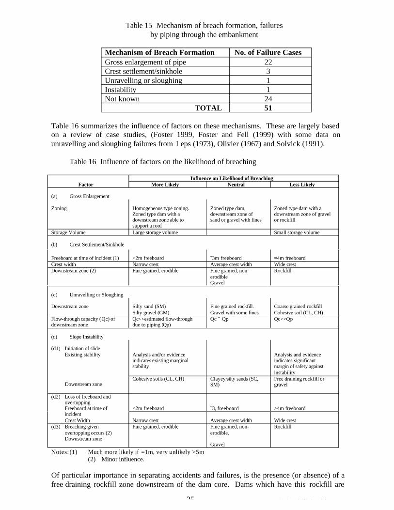
Table 15 Mechanism of breach formation, failures by piping through the embankment
Mechanism of Breach Formation No. of Failure Cases Gross enlargement of pipe 22 Crest settlement/sinkhole 3 Unravelling or sloughing 1 Instability 1 Not known 24
TOTAL 51
Table 16 summarizes the influence of factors on these mechanisms. These are largely based on a review of case studies, (Foster 1999, Foster and Fell (1999) with some data on unravelling and sloughing failures from Leps (1973), Olivier (1967) and Solvick (1991).
Table 16 Influence of factors on the likelihood of breaching
Influence on Likelihood of BreachingFactor More Likely Neutral Less Likely
(a) Gross Enlargement
Zoning Homogeneous type zoning. Zoned type dam, Zoned type dam with a Zoned type dam with a downstream zone of downstream zone of gravel downstream zone able to sand or gravel with fines or rockfill support a roof
Storage Volume Large storage volume Small storage volume
(b) Crest Settlement/Sinkhole
Freeboard at time of incident (1) <2m freeboard ˜3m freeboard =4m freeboard Crest width Narrow crest Average crest width Wide crest Downstream zone (2) Fine grained, erodible Fine grained, non- Rockfill
erodible Gravel
(c) Unravelling or Sloughing
Downstream zone Silty sand (SM) Fine grained rockfill. Coarse grained rockfill Silty gravel (GM) Gravel with some fines Cohesive soil (CL, CH)
Flow-through capacity ( Qc) of Qc<<estimated flow-through Qc ˜ Qp Qc>>Qp downstream zone due to piping (Qp)
(d) Slope Instability
(d1) Initiation of slide Existing stability Analysis and/or evidence Analysis and evidence
indicates existing marginal indicates significant stability margin of safety against
instability Cohesive soils (CL, CH) Clayey/silty sands (SC, Free draining rockfill or
Downstream zone SM) gravel
(d2) Loss of freeboard and overtopping Freeboard at time of <2m freeboard ˜3, freeboard >4m freeboard incident Crest Width Narrow crest Average crest width Wide crest
(d3) Breaching given Fine grained, erodible Fine grained, non- Rockfillovertopping occurs (2) erodible.Downstream zone
GravelNotes: (1) Much more likely if =1m, very unlikely >5m
(2) Minor influence.
Of particular importance in separating accidents and failures, is the presence (or absence) of a free draining rockfill zone downstream of the dam core. Dams which have this rockfill are
25 Attachment 5 White Paper 2.doc
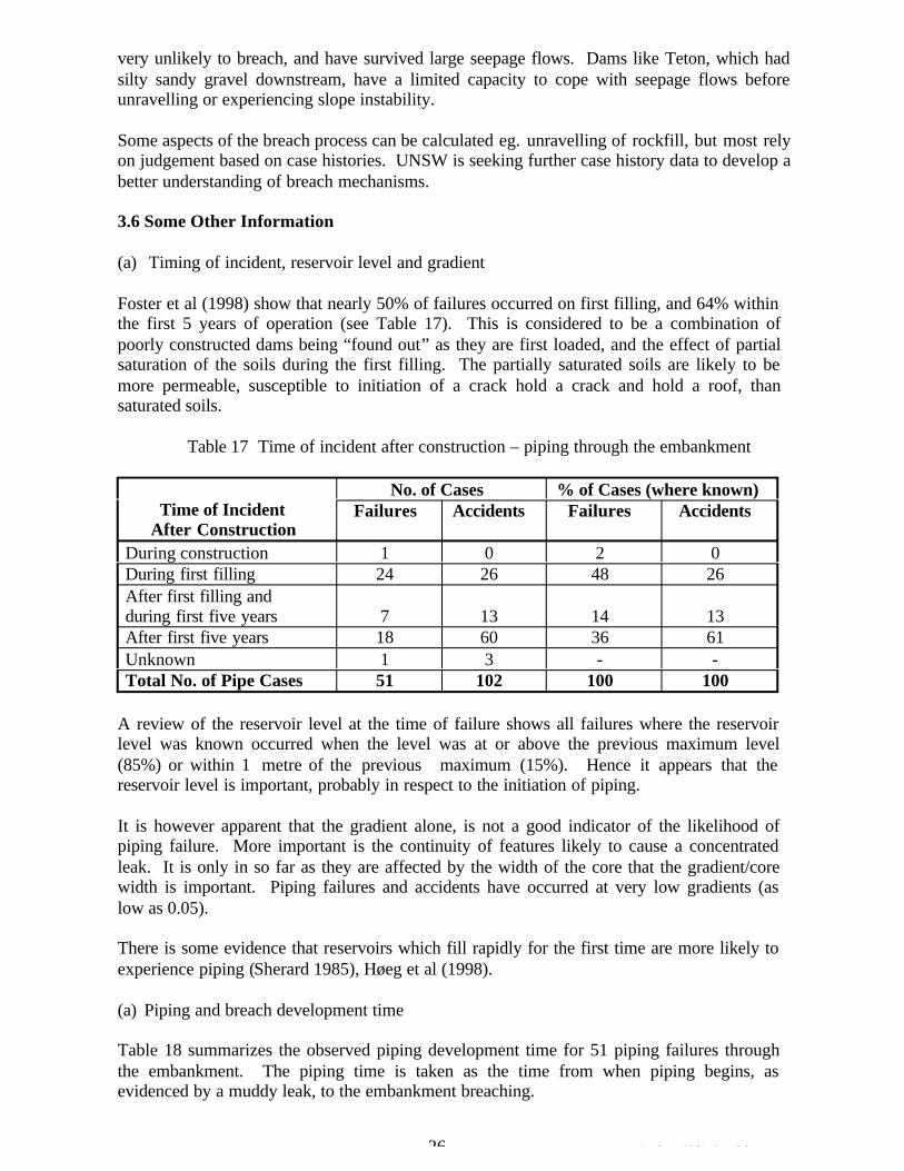
very unlikely to breach, and have survived large seepage flows. Dams like Teton, which had silty sandy gravel downstream, have a limited capacity to cope with seepage flows before unravelling or experiencing slope instability.
Some aspects of the breach process can be calculated eg. unravelling of rockfill, but most rely on judgement based on case histories. UNSW is seeking further case history data to develop a better understanding of breach mechanisms.
3.6 Some Other Information
(a) Timing of incident, reservoir level and gradient
Foster et al (1998) show that nearly 50% of failures occurred on first filling, and 64% within the first 5 years of operation (see Table 17). This is considered to be a combination of poorly constructed dams being “found out” as they are first loaded, and the effect of partial saturation of the soils during the first filling. The partially saturated soils are likely to be more permeable, susceptible to initiation of a crack hold a crack and hold a roof, than saturated soils.
Table 17 Time of incident after construction – piping through the embankment
Time of Incident After Construction
No. of Cases % of Cases (where known) Failures Accidents Failures Accidents
During construction 1 0 2 0 During first filling 24 26 48 26 After first filling and during first five years 7 13 14 13 After first five years 18 60 36 61 Unknown 1 3 - -Total No. of Pipe Cases 51 102 100 100
A review of the reservoir level at the time of failure shows all failures where the reservoir level was known occurred when the level was at or above the previous maximum level (85%) or within 1 metre of the previous maximum (15%). Hence it appears that the reservoir level is important, probably in respect to the initiation of piping.
It is however apparent that the gradient alone, is not a good indicator of the likelihood of piping failure. More important is the continuity of features likely to cause a concentrated leak. It is only in so far as they are affected by the width of the core that the gradient/core width is important. Piping failures and accidents have occurred at very low gradients (as low as 0.05).
There is some evidence that reservoirs which fill rapidly for the first time are more likely to experience piping (Sherard 1985), Høeg et al (1998).
(a) Piping and breach development time
Table 18 summarizes the observed piping development time for 51 piping failures through the embankment. The piping time is taken as the time from when piping begins, as evidenced by a muddy leak, to the embankment breaching.
26 Attachment 5 White Paper 2.doc

Table 18 Piping and breach development time for failures by piping through the embankment – (Foster 1999, Foster et al 1998)
Time for Piping and Breach Number of Cases Unknown 23 Not observed, but probably <12 hrs 11 >24 hrs 3 12-24 hrs 2 6-12 hrs 3 <6 hrs 9
The relatively short times mean that there is limited scope for intervention. However it should be emphasised these data are for failures, not accidents.
4. RESEARCH NEEDS
We have attempted to summarize the research needs in table 19, under the phase of the piping process. It is hoped that this may provide a starting point for our discussions in Denver.
27 Attachment 5 White Paper 2.doc
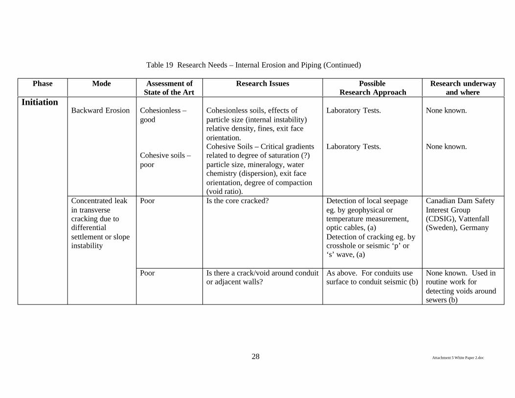
Table 19 Research Needs – Internal Erosion and Piping (Continued)
Phase Mode Assessment of Research Issues Possible Research underway State of the Art Research Approach and where
Initiation Backward Erosion Cohesionless – Cohesionless soils, effects of Laboratory Tests. None known.
good particle size (internal instability) relative density, fines, exit face orientation.
Cohesive soils – Cohesive Soils – Critical gradients related to degree of saturation (?)
Laboratory Tests. None known.
poor particle size, mineralogy, water chemistry (dispersion), exit face orientation, degree of compaction (void ratio).
Concentrated leak Poor Is the core cracked? Detection of local seepage Canadian Dam Safety in transverse eg. by geophysical or Interest Group cracking due to temperature measurement, (CDSIG), Vattenfall differential optic cables, (a) (Sweden), Germany settlement or slope Detection of cracking eg. by instability crosshole or seismic ‘p’ or
‘s’ wave, (a)
Poor Is there a crack/void around conduit or adjacent walls?
As above. For conduits use surface to conduit seismic (b)
None known. Used in routine work for detecting voids around sewers (b)
28 Attachment 5 White Paper 2.doc
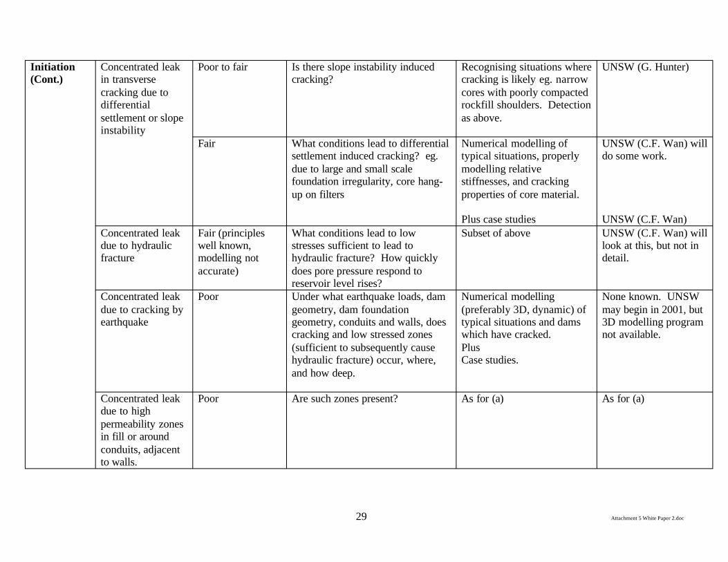
Initiation (Cont.)
Concentrated leak in transverse
Poor to fair Is there slope instability induced cracking?
Recognising situations where cracking is likely eg. narrow
UNSW (G. Hunter)
cracking due to differential
cores with poorly compacted rockfill shoulders. Detection
settlement or slope instability
as above.
Fair What conditions lead to differential settlement induced cracking? eg. due to large and small scale foundation irregularity, core hang-up on filters
Numerical modelling of typical situations, properly modelling relative stiffnesses, and cracking properties of core material.
UNSW (C.F. Wan) will do some work.
Plus case studies UNSW (C.F. Wan) Concentrated leak Fair (principles What conditions lead to low Subset of above UNSW (C.F. Wan) will due to hydraulic well known, stresses sufficient to lead to look at this, but not in fracture modelling not hydraulic fracture? How quickly detail.
accurate) does pore pressure respond to reservoir level rises?
Concentrated leak Poor Under what earthquake loads, dam Numerical modelling None known. UNSW due to cracking by earthquake
geometry, dam foundation geometry, conduits and walls, does cracking and low stressed zones
(preferably 3D, dynamic) of typical situations and dams which have cracked.
may begin in 2001, but 3D modelling program not available.
(sufficient to subsequently cause hydraulic fracture) occur, where,
Plus Case studies.
and how deep.
Concentrated leak Poor Are such zones present? As for (a) As for (a) due to high permeability zones in fill or around conduits, adjacent to walls.
Attachment 5 White Paper 2.doc 29
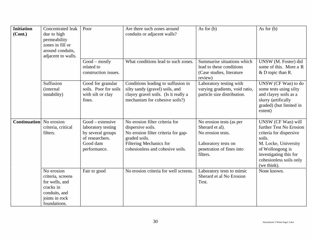
Initiation (Cont.)
Concentrated leak due to high
Poor Are there such zones around conduits or adjacent walls?
As for (b) As for (b)
permeability zones in fill or around conduits, adjacent to walls.
Good – mostly What conditions lead to such zones. Summarise situations which UNSW (M. Foster) did related to lead to these conditions some of this. More a R construction issues. (Case studies, literature & D topic than R.
review) Suffusion Good for granular Conditions leading to suffusion in Laboratory testing with UNSW (CF Wan) to do (internal instability)
soils. Poor for soils with silt or clay
silty sandy (gravel) soils, and clayey gravel soils. (Is it really a
varying gradients, void ratio, particle size distribution.
some tests using silty and clayey soils as a
fines. mechanism for cohesive soils?) slurry (artifically graded) (but limited in extent)
Continuation No erosion criteria, critical
Good – extensive laboratory testing
No erosion filter criteria for dispersive soils.
No erosion tests (as per Sherard et al).
UNSW (CF Wan) will further Test No Erosion
filters. by several groups of researchers. Good dam
No erosion filter criteria for gap-graded soils. Filtering Mechanics for
No erosion tests.
Laboratory tests on
criteria for dispersive soils. M. Locke, University
performance. cohesionless and cohesive soils. penetration of fines into filters.
of Wollongong is investigating this for cohesionless soils only (we think).
No erosion Fair to good No erosion criteria for well screens. Laboratory tests to mimic None known. criteria, screens Sherard et al No Erosion for wells, and Test. cracks in conduits, and joints in rock foundations.
Attachment 5 White Paper 2.doc 30

Continuation (Cont.)
Continuing and excessive erosion
Fair Continuing and excessive erosion criteria for a wide range of soils.
Laboratory testing using “No erosion” set-up, plus review
UNSW (CF Wan) is doing some further
criteria. of case studies. laboratory and case study work.
Fines content of filters – will the filter “hold a
Fair The effect of fines content, plasticity and compaction of filters, on whether the filter will hold a
Laboratory testing (but not clear how). Plus case studies.
None known.
crack”. crack. Minimum Fair. Depth of penetration of fines (base Laboratory tests Wollongong Uni. (M. thickness/depth of penetration of fines.
soil) into filter. Locke) – as a by-product of overall mechanics.
Progression Ability of pipe to Fair Effect of soil classification, fines Laboratory tests, with None known. to Form a stay open - in content, degree of compaction, varying conditions and hole Pipe embankments degree of saturation, and diameter/shape.
fluctuations in head and flow, on Plus whether a pipe will remain open. Case studies UNSW (CF Wan) will
assess some case studies.
Ability of pipe to Poor As above, but for foundation soils, Laboratory testing as above. None known stay open – in such as alluvials, fluvioglacials etc. foundations. Effect of interlayering. Case studies. UNSW (CF Wan) will
assess some case studies.
Effect of Poor to fair. What zoning will give flow Case studies – embankments, UNSW (CF Wan) will limitation of limitation and crack stopping? foundations and embankment assess some case flows and “crack to foundations. studies. stoppers”. Particle size, critical gradients to Laboratory tests simulating Virginia Tech. (Prof.
mobilize crack stopping, including crack stopper, core and M. Duncan) was/is material from upstream transition filter/transition. planning some tests. zones with high fines content.
Attachment 5 White Paper 2.doc 31
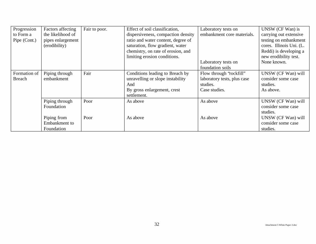
Progression to Form a Pipe (Cont.)
Factors affecting the likelihood of pipes enlargement (erodibility)
Fair to poor. Effect of soil classification, dispersiveness, compaction density ratio and water content, degree of saturation, flow gradient, water chemistry, on rate of erosion, and limiting erosion conditions.
Laboratory tests on embankment core materials.
Laboratory tests on foundation soils
UNSW (CF Wan) is carrying out extensive testing on embankment cores. Illinois Uni. (L. Reddi) is developing a new erodibility test. None known.
Formation of Breach
Piping through embankment
Fair Conditions leading to Breach by unravelling or slope instability And By gross enlargement, crest settlement.
Flow through “rockfill” laboratory tests, plus case studies. Case studies.
UNSW (CF Wan) will consider some case studies. As above.
Piping through Foundation
Piping from Embankment to Foundation
Poor
Poor
As above
As above
As above
As above
UNSW (CF Wan) will consider some case studies. UNSW (CF Wan) will consider some case studies.
Attachment 5 White Paper 2.doc 32
5. REFERENCES
Arulanandan, K. and Perry, E.B. (1983). Erosion in relation to filter design criteria in earth dams. Journal of the Geotechnical Engineering Division, ASCE. 109(GT5), pp.682-698.
Arulanandan, K., Loganathan, P. and Krone, R.B. (1975). Pore and eroding fluid influences on the surface erosion of soils. Journal of the Geotechnical Engineering Division, ASCE.101(GT1), pp.55-66.
Bakker, K.J. (1987). Hydraulic Filter Criteria for Banks. European Conference on Soil Mechanics and Foundation Engineering, Dublin.
Bickel, J.O. and Kuesel, T.R. (1992). Tunnel Engineering Handbook. Krieger Publishing Company, Flordia.
Brauns, J. and Witt, K.J. (1987). Proposal for an Advanced Concept of filter Design. Proc. 9th European Conference on Soil Mechanics and Foundation Engineering. Dublin.
Burenkova, V.V. (1993). Assessment of suffusion in non-cohesive and graded soils. Filters in Geotechnical and Hydraulic Engineering, Brauns, Heibaum & Schuler (eds.), Balkema, Rotterdam, pp.357-360.
Cedergren, H.R. (1989). Seepage, Drainage, and Flow Nets. Third Edition, John Wiley. CFGB (1997). Internal Erosion: Typology, Detection, Repair. Barrages and Reservoirs
No.6. Comité Francais des Grands Barages, Le Bourget-du-lac Cedex. Chapius, R.P. and Gatien, T. (1986). An improved rotating cylinder technique for
quantitative measurements of scour resistance of clays. Canadian Geotechnical Journal. 23(1), pp.83-87.
Charles, J.A. (1997). General Report, Special problems Associated with Earthfill Dams. Nineteenth International Congress on Large Dams, Florence, GR Q73, Vol.II, pp.1083-1198.
Charles, J.A., Tedd, P. and Holton, I.R. (1995). Internal erosion in clay cores of British dams. Research and Development in the Field of Dams, Crans-Montana, Switzerland, Swiss national Committee on Large Dams. Pp.59-70.
Den-Adel, H., Koenders, M.A. and Bakker, K.J. (1994). The Analysis of Relaxed Criteria for Erosion Control Filters. Canadian Geotech. J. Vol.31, pp.829-840.
Fell, R., MacGregor, J.P., and Stapledon, D.H. (1992). Geotechnical Engineering of Embankment Dams. Balkema, 1992.
Foster, M. and Fell, R. (2000). Use of Event Trees to Estimate the Probability of Failure of Embankment Dams by Internal Erosion and Piping. ICOLD 20th Congress on Large Dams, Beijing, Q76-R16, 237-259.
Foster, M.A. (1999). The probability of failure of embankment dams by internal erosion and piping. PhD Thesis, School of Civil and Environmental Engineering, University of New South Wales, Sydney, Australia.
Foster, M.A. and Fell, R. (1999). A Method for Assessing Embankment Dam Filters Which do not Satisfy Modern Design Criteria. UNICIV Report No. R-376, School of Civil and Environmental Engineering, The University of New South Wales. ISBN: 85841 343 4.
Hanson, G.J. (1992). Erosion resistance of compacted soils. Transportation Research Record 1369, pp.26-30.
Hanson, G.J. and Robinson, K.M. (1993). The influence of soil moisture and compaction on spillway erosion. Transactions of the ASAE. 36(5), pp.1349-1352.
Høeg, K., Johansen, P.M., Kjærnsli, B. and Torblaa, I. (1998). Internal Erosion in Embankment Dams. Research Project Sponsored by Norwegian Electricity Federation (EnFO). (In Norwegian with English summary).
33
Honjo, Y. and Veneziano, D. (1989). Improved filter criterion for cohesionless soils. Journal of Geotechnical Engineering, ASCE, 115 (1), pp.75-94.
ICOLD (1994). Bulletin 95 – Embankment Dams Granular Filters and Drains. Review and Recommendations. ICOLD.
ICOLD (1994). Bulletin 95, Embankment Dams. Granular Filters and Drains. International Commission on Large Dams, Paris.
Kenney, T.C. and Lau, D. (1985). Internal stability of granular filters. Canadian Geotechnical Journal, Vol.22, pp.215-225.
Kenney, T.C. and Westland (1993). Laboratory study of segregation of granular filter materials. Filters in Geotechnical and Hydraulic Engineering, Brauns, Heibaum and Schuler (Eds.). Balkema, Rotterdam, pp.313-319.
Lafleur, J., Mlynarek, J. and Rollin, A.L. (1989). Filtration of Broadly Graded Cohesionless Soils. J. Geotech Eng. ASCE, Vol.115, No.12, pp.1747-1768.
Lafleur, J., Mlynarek, J. and Rollin, A.L. (1993). Filter Criteria for Well Graded Cohesionless Soils, in Filters in Geotechnical and Hydraulic Engineering, Editors Braun, Helbaum and Schuler. Balkema, Rotterdam, pp.97-106.
Leps, T.M. (1973). Flow through rockfill dams. In Embankment Dam Engineering, Hirschfeld and Poulos eds., John Wiley and Sons, pp.87-107.
Olivier, H. (1967). Through and overflow rockfill dams – new design techniques. Proceedings Institution of Civil Engineers, Vol.36, March, pp.433-464.
Peck, R. (1990). Interface between core and downstream filter. Proc. H Bolton Seed Memorial Symposium, BiTech Publishers, Vol.2, pp.237-251.
Ripley, C.F. (1986) Discussion of: Internal stability of granular filters. Canadian Geotechnical Journal, 23, pp. 255-258.
Schuler, U. and Brauns, J. (1997). The Safety of Geotechnical Filters. Hydropower and Dams, Issue 6, pp.72-74.
Sherard, J.L. (1953). Influence of soil properties and construction methods on the performance of homogeneous earth dams. PhD Thesis, Harvard University.
Sherard, J.L. (1973). Embankment dam cracking. In Embankment Dam Engineering, Hirschfeld and Poulos eds. John Wiley & Sons, New York, pp.271-353.
Sherard, J.L. (1979). Sinkholes in dams of coarse, broadly graded soils. Thirteenth International Congress on Large Dams, New Dehli, ICOLD. Q.49R.2, pp.325-334.
Sherard, J.L. (1983) Discussion of: Design of filters for clay cores of dams. Journal of Geotechnical Engineering ASCE, 109 (9), pp. 1195-1197.
Sherard, J.L. (1985). Hydraulic fracturing in embankment dams. Proccedings, Symposium on Seepage and Leakage from Dams and Impoundments, (Volpe, R.L., and Kelly, W.E. eds.), ASCE, pp.115-141.
Sherard, J.L. and Dunnigan, L.P. (1985). Filters and leakage control in embankment dams. Proccedings, Symposium on Seepage and Leakage from Dams and Impoundments, (Volpe and Kelly eds.), ASCE, pp.1-30.
Sherard, J.L. and Dunnigan, L.P. (1989). Critical filters for impervious soils. Journal of Geotehnical Engineering, ASCE, 115 (7), pp.927-947.
Sherard, J.L., (1985) Memorandum 1A to 1H, Unpublished reports of filter research carried out in the Lincoln, Nebraska, Soil Conservation Service Soil Mechanics Laboratory.
Sherard, J.L., Decker, R.S. and Ryker, N.L. (1972(a)). Hydraulic fracturing in low dams of dispersive clay. Proceedings, Specialty Conference on Performance of Earth and Earth-Supported Structures, ASCE, Vol.1, Part 1, pp.653-689.
Sherard, J.L., Decker, R.S. and Ryker, N.L. (1972(b)). Piping in earth dams of dispersive clay. Proceedings, Specialty Conference on Performance of Earth and Earth-Supported Structures, ASCE, Vol.1, Part 1, pp.589-626.
34
Sherard, J.L., Dunnigan, L.P. and Talbot, J.R. (1984a) Basic properties of sand and gravel filters. Journal of Geotechnical Engineering, ASCE, 110 (6), pp. 684-700.
Sherard, J.L., Dunnigan, L.P. and Talbot, J.R. (1984b) Filters for silts and clays. Journal of Geotechnical Engineering, ASCE, 110 (6), pp. 701-718.
Sherard, J.L., Woodward, R.J., Gizienski, S.F., and Clevenger, W.A. (1963). Earth and Earth-Rock Dams, John Wiley & Sons.
Skempton, A. and Brogan J.M. (1994). Experiments on Piping in Sandy Gravels. Geotechnique 44 No.3, 449-460.
Solvik, Ø (1991). Throughflow and stability problems in rockfill dams exposed to exceptional loads, Sixteenth International Congress on Large Dams, Q.67 R.20, ICOLD, pp.333-343.
Terzaghi, K. and Peck, R.B. (1967). Soil Mechanics in Engineering Practice. Second Edition, John Wiley.
US Army Corps of Engineers (1985). Engineering and Design. Seepage Analysis and Control for Dams. EM1110-2-1901.
USBR (1987). Guidelines for Controlling Seepage Along Conduits Through Embankments, ACER Technical Memo No.9, U.S. Department of the Interior, Bureau of Reclamation.
USDA – SCS (1994) Vaughan, P.R., and Soares, H.F. (1982). Design of filters for clay cores of dams. Journal of
Geotechnical Engineering Division, ASCE, 108(GT1), pp.17-31. Von Thun, J.L. (1996). Understanding seepage and piping failures – the No.1 dam safety
problem in the west. ASDSO Western Regional Conference, Lake Tahoe, Nevad. Witt, K.J. (1980). Filtrations verhalten und Bemessung von Erdstoff – Filtern. Veroffentl.
Inst. F. Boden u. Felsmech. Univers. Karlsruhe, Heft 104. Witt, K.J. (1993). Reliability Study of Granular Faction. Behaviour of Coarse and Well
Graded Filters in Filters in Geotechnical and Hydraulic Engineering. Editors Brauns, Helbaurn and Schules. Balkema, Rotterdam, pp.35-41.
35

Assessing the Risk of a Seepage-Related Dam FailureBy Means of Failure Mode Identification, Risk Analysis,
and Monitoring Practices
A “White Paper” for the October 2000 ASDSO/FEMA Seepage Workshop
William O. Engemoen U.S. Bureau of Reclamation
October 3, 2000
I. Purpose
In the survey of interest for workshop topics, the three topics of this paper all received significant expressions of interest, and were subsequently combined into a single “white paper.” The three topics to be addressed herein, listed in order of the number of votes received, are: 1) inspection of dams for detection of seepage problems, 2) analysis of risks associated with seepage and internal erosion, and 3) failure modes associated with seepage and internal erosion. This paper presents the “state of practice” (admittedly biased towards the practices followed by the Bureau of Reclamation) with regards to the surveillance and monitoring of dams, and the subsequent use of this information in the evaluation of the potential risks posed from a seepage-related failure at a given dam. Potential areas of research relative to these topics are included at the end of the paper.
II. Overview of Reclamation Process for Evaluating Dam Safety Issues
Reclamation’s inventory of dams includes around 300 major embankments that have the potential to result in life loss in the event of failure. Typically, these dams are observed and inspected frequently by dam tenders and operations personnel, most likely during the operation season when the reservoirs are at their highest levels. However, formal examinations and evaluations are done less frequently, but in a thorough and prescripted manner. Annually, Reclamation representatives from the nearest Area Office examine the dam and fill out an inspection report. Typically, these inspectors are generalist (as opposed to specialist) engineers very familiar with the dam and it’s operations, and can readily distinguish changes from year to year. All inspectors attend regular training in dam safety inspections. On a 3-year cycle, each dam is examined by a team originating in the Regional Office, including the regional examination specialist. This examination is referred to a Periodic Facility Review and includes a rather thorough review and reporting of all past dam safety and Operation and Maintenance (O&M) recommendations made in the past. Finally, on a 6-year cycle, each dam is examined/evaluated by a team of specialists from the Technical Service Center that includes an Instrumentation Engineer, an Examination Specialist, and a Senior Dam Engineer. This process is called a Comprehensive Facility Review (CFR) and includes: a site examination with the Area and Regional Office representatives and operational personnel; a thorough review of all instrumentation and past performance, as well as suggestions for changes to the monitoring program; a review of all available documentation of the original design and construction, including all analyses and design assumptions and how they compare to today’s state of practice; a discussion of potential failure modes; a new look at the probabilistic earthquake and flood
1 Attachment 6 White Paper 3.doc
loadings that would be expected for that site; a determination of the estimated consequences (loss of life) in the event of a dam failure; a quantitative evaluation of the risks posed due to the various loadings ; and a listing of conclusions, recommendations, and further actions required to ensure public safety.
If the conclusions reached by the CFR team indicate that significant risks may be present at a dam, additional higher level studies and risk analyses are then undertaken. Such higher level studies may include the collection of additional data, the installation of additional instrumentation, changes to the surveillance extent or frequency, performance of specific or updated analyses, and likely the performance of a formal, comprehensive analysis of risk including detailed event trees and in accordance with established Reclamation methodology. The decisions resulting from these studies and additional risk assessments may include: 1) do nothing, as risks are not high enough to justify actions; 2) restrict the reservoir, or some similar non-structural response; 3) structurally modify the dam to mitigate any deficiency; 4) enhance monitoring and emergency management practices to ensure timely detection and warning capability that would substantially reduce and hopefully eliminate loss of life; and 5) a combination of these measures. A Risk Reduction Analysis would typically be performed to provide information to the decision process as to the expected benefits of non-structural and structural responses.
The above overview is a generalized summary of the process Reclamation employs to monitor its dams and attempt to detect any potential dam safety deficiencies, whether from flood or earthquake loading, or from the static loading which includes the threat of seepage-related failure. What follows will be a more detailed discussion of the various processes as they relate to the evaluation of the potential for seepage-related dam failure.
The discussion will start with the failure mode evaluation, as the understanding of how a specific dam might fail due to seepage is a key first step. What follows failure modes is logically an evaluation of the probability of each failure mode - the risk analysis. Inspection and monitoring of the dam is discussed last in the order, to highlight lessons learned, or things to look for, that often are discovered during the failure mode and risk analysis process.
III. Failure Mode Evaluation
General - In order to best detect potentially threatening seepage problems and to be able to understand and estimate the risks posed by seepage, it is important to have a detailed understanding of the specific means by which a particular dam might fail under seepage conditions. A well thought out discussion and analysis of the specific means by which a given dam could fail is referred to as a failure mode evaluation. It is important that this evaluation be detailed, rather than too general. For example, saying that the dam could fail by “piping of the core” is not sufficient. A far better description would be “erosion of the low plasticity core materials through the coarse, openwork shell materials, and into the unprotected toe drain, resulting in backward erosion and formation of a sinkhole into the reservoir where the subsequent outflow erodes and breaches the embankment.” In other words, the entire failure process needs to be understood and logically described. This type of understanding and description will help inspectors know where and what to look for during dam surveillance, and
2 Attachment 6 White Paper 3.doc
will help the risk analysts better construct event trees and determine probabilities of failure for each step of the failure process. With this evaluation, it also helps to identify locations in the dam where particular failures are most likely to originate. Openwork foundation soils may be present, for example, between stations 3+00 and 6+50 along the dam alignment, or foundation grouting or surface treatment may not have extended past a given station on one abutment. This type of information may be critical to the inspectors or risk analysts as well.
Failure mode evaluations are best performed by a small group of very experienced designers and geologists and would ideally include at least some individuals with a thorough understanding of the dam, site specific knowledge of surveillance and monitoring procedures, and some understanding of risk analysis [1]. It is essential that this group carefully study all available records of the site geology, design and construction details, and structural performance. Attention to detail and thorough discussion will lead to a better development and understanding of the failure modes.
Types of Seepage-Related Failures - Seepage passing through and under an embankment dam can, in the right situation, lead to dam failure by one of several mechanisms [2,3,7]. Any dam may have one or more of these potential failure modes.
Piping - Erosion initiates at a downstream exit point of a seepage path within the dam or foundation. As soil particles are carried away by the exiting seepage, the erosion process continues in a backward (upstream) direction. Classical piping is characterized by the formation of an open tunnel extending from the downstream seepage exit point back upstream toward the reservoir. For piping to occur, several conditions must be present, including:
- there must be a flow path with water - there must be an unprotected (open, unfiltered) exit from which soil can escape - there must be erodible material within the flow path that can be transported to the exit - the material being piped must be able to support a “pipe” or “roof,” or must be adjacent to a feature such as a overlying clay layer or concrete structure that would provide a “roof” -sufficient seepage gradients, or even the presence of a concentrated leak, may be required to initiate the erosion process (although that depends on the soil erodibility)
Seepage Erosion, or “Scour” - Loss of material occurs at an erosional surface where a concentrated flow is located, such as a crack through a dam or the dam/foundation contact. Continued flow causes the erosion to progress, creating a larger and larger eroded area.
Internal Erosion by Suffosion (Internal Instability) - In an internally unstable soil (typically gap-graded), flow through this material can cause part of the finer grained portion of the soil matrix to be washed through the coarser grained portion of the matrix.
3 Attachment 6 White Paper 3.doc
High, Confined Pore Pressures in Foundation - Several different descriptions including uplift, heave, and blowout are lumped into this category, and generally describe a situation in which the foundation seepage pressures exceed the effective weight of the overlying soil, typically at the downstream toe of the dam. Failure scenarios include a slope failure or a rupture in the confining layer that in turn might lead to a piping failure. It is generally thought that these failure mechanisms would be most likely to occur the first time a reservoir reaches a critical elevation, which implies that first filling, new water levels that exceed historic highs, and possibly increasing foundation pressures would be needed for these to be failure modes.
Three Major Classifications of Internal Erosion Failure Modes - Based on the work done by the University of New South Wales [4,7], Reclamation often evaluates potential internal erosion failure modes on the basis of 3 different types: erosion through the embankment, erosion through the foundation, and erosion of the embankment into or at the foundation.
Internal Erosion Through the Embankment - This failure mode is typified by internal erosion occurring solely within the embankment, and could include classical piping, scour, or suffosion. Erosion would progress by escape of embankment materials into downstream areas or zones, and would continue until it eventually reaches the reservoir and causes a dam breach. A major subset of this failure mode includes internal erosion associated with a penetrating structure such as an outlet works or spillway conduit located within the embankment. Studies of case histories suggest that around 50 percent of all failures due to embankment erosion appeared to initiate around or near conduits. This could be due to a number of factors, including: leaks into or out of the conduit due to structure flaws (pipe deterioration, separating joints, differential settlement cracks, etc.), poor compaction against the sides of conduits, or stress concentrations in the embankment adjacent to the conduit.
Internal Erosion Through the Foundation - This failure mode is typified by internal erosion occurring solely within the foundation, involving only foundation materials (which could be soil, rock, or both) in the erosion process. This type of failure could also include classical piping, scour, or suffosion, which would start the initiation of erodible foundation material. Erosion would then progress by escape of material into downstream areas, and would continue backwards until it reached the reservoir. In latter stages of this process, the embankment would start caving or stoping into the foundation void, leading to ultimate dam breach.
Internal Erosion of Embankment into/at Foundation - This particular failure mode is typified by an internal erosion process involving both the embankment and foundation, and includes two distinctly different failure modes:
• Internal erosion of embankment into the foundation - Erosion initiates at the embankment-foundation contact due to a seepage gradient from the embankment into the foundation materials, which may be soil or rock. This requires higher seepage pressures in the embankment than in the foundation, sufficient permeability of the foundation material to allow soil transport, and an unfiltered
4 Attachment 6 White Paper 3.doc
exit downstream (or else a sufficient storage volume within the foundation material). Once initiated, erosion continues backward until dam breach results. Case histories of failures reveal that embankment erosion into rock discontinuities is more typical than embankment erosion into pervious foundation soils [4].
• Internal erosion by foundation flow at the contact - Erosion begins by a concentrated flow of water in the foundation at its contact with the embankment. The seepage flow erodes the embankment material into downstream areas of the foundation or embankment, ultimately leading to a dam breach. A key requirement for this failure mode is the presence of significant flow at the embankment/foundation contact.
IV. Analysis of Risk Posed by Failure Modes
General - The term “risk” as used by Reclamation [5] is best defined by the equation:
Risk = [Probability of the Loading] x [Probability of Adverse Response given the Loading] x [Adverse Consequences given the Failure]
Where: Probability of the Loading is the annual probability that the load responsible for a failure
will occur (such as a 100-year flood, a 10,000-year earthquake, etc.) Probability of Adverse Response given the Loading is the likelihood that the dam will fail
under the specific loading (ranges from 0 to 1.0) Adverse Consequences given the Failure is typically expressed in terms of the estimated
number of lives lost given a dam failure
In Reclamation, there are different levels of risk analyses used at various points in dam safety studies, including the following:
Risk Based Profiling System: This is essentially a “portfolio ranking” tool that utilizes a standardized set of questions to calculate a quantitative point total for each dam in a given inventory [6]. By applying this profiling system to all dams, an agency then has a system that can compare and rate relative risks between their dams. Reclamation has only recently developed this system, and is currently developing plans on how to most effectively use it for dam safety prioritizing and decision making.
CFR Risk Analysis: As mentioned earlier, a Comprehensive Facility Review is conducted on Reclamation dams every 6 years. As part of this CFR, the Senior Dam Engineer is expected to use existing information, judgement, and considerable experience to quantitatively estimate the risks posed by various failure modes for a given dam. This level of risk analysis is much less detailed and complicated than the team approach described below, and is therefore considered more of a screening-level risk analysis.
Issue Evaluation Risk Analyses: This level of risk analysis is generally the most comprehensive type utilized by Reclamation. It is comprised of two trained facilitators and a team that usually includes subject experts, design engineers and geologists most familiar with the dam, and field personnel responsible for inspection and maintenance of
5 Attachment 6 White Paper 3.doc
the structure. This type of analysis includes preparatory time, usually about of week of meeting time, and then a fairly lengthy effort to document the processes followed and conclusions developed from the risk meetings.
In general, Reclamation tends to use the first two types of risk assessments to help determine what types of further studies are needed on a dam, or the priority in which dams should have additional dam studies scheduled, if such studies are needed. The third, and much more comprehensive, type of analysis is typically utilized when deciding whether to modify a given dam. A very important point to comprehend here with the use of any of these three types of risk analyses is that they should serve as a tool to promote a more thorough understanding of the technical issues at a dam and help decision makers with determining a prudent course of action. A risk analysis is not, by itself, intended to serve as the ultimate “answer” to whether a dam safety issue requires remediation. Rather, the risk analysis should compliment other technical analyses, non-technical considerations, and judgements, and form an additional consideration for deciding future required action.
Basic Risk Analysis Methods for Analyzing Seepage Risks - There are two primary methods for quantifying the risk of seepage-related dam failures: 1) reference to historical databases of performance, and 2) decomposition, or the use of event trees.
Comparison to Historical Performance: A simpler, screening-level risk analysis like that performed during a CFR will utilize historical performance data, and generally follow the procedure as documented by researchers at the University of New South Wales [4]. In essence, a dam is categorized into a particular type of dam (with a resulting failure probability from the historical database), receives site specific adjustments due to many factors that would affect its susceptibility to internal erosion, and then an adjusted annual probability of failure is calculated. Although the method contains some simplifications or generalizations, it nonetheless serves as a very useful tool for developing preliminary estimates of risks posed by internal erosion failure modes, and is based on a very comprehensive look at historical dam performance.
Event Trees: Higher level risk analysis will typically utilize the event tree method which decomposes the failure modes into discrete nodes. Although each specific risk analysis for a given dam may require a particular event tree, our experience has shown that a “generic” event tree is often satisfactory or at least provides a good starting point. The generic tree used by Reclamation is based in large part on the work done by researchers at the University of New South Wales [7], but customized for our work. This event tree is shown on Figure 1. A separate event tree is typically developed and analyzed for each internal erosion failure mode, as there are enough differences between the various failure modes to warrant a unique tree for each one.
Details of Event Tree for Internal Erosion - Following are brief descriptions of each node on the event tree, along with some key considerations. Much more detail, including tables which list considerations for each node, may be found in Appendix E [3] of Reclamation’s Risk Analysis Methodology.
6 Attachment 6 White Paper 3.doc
Initiation: Many believe that some type of concentrated leak through the dam or foundation is needed to develop an internal erosion problem. An evaluation of case histories would support this position over the more unlikely supposition that “spontaneous erosion” would suddenly develop where previously no leak existed. Based on this assumption, this first node essentially asks the question “What is the probability that a concentrated leak exists in the dam (or foundation, depending on which failure mode is being analyzed)?” Some of the site specific issues to consider in establishing the probability of this node include: the presence and fluctuations of seepage, the location and details of any penetrating conduits, the presence of permeable layers, composition of core material and likelihood for cracking, the gradations of embankment and foundation materials, and the type of foundation treatment.
Continuation of Internal Erosion: For internal erosion to continue, even given a concentrated leak, there needs to be an unprotected exit. Thus, this node seeks the probability of an unfiltered exit to the seepage/erosion path. Information to consider in estimating this node includes factors such as embankment zoning, the filter compatibility of surrounding embankment and foundation materials, and the presence of features such as toe drains or relief wells that may not have been designed according to proper filter criteria.
Progression of the Internal Erosion Process: There are three pieces to the consideration of whether erosion will progress once the process has initiated at the downstream end of the seepage path, and these are shown as three different nodes on the event tree. These three nodes are not necessarily conditionally dependent on one another, but nonetheless are all considered critical to the progression of the erosion process.
• Ability to support a roof - This node refers to the ability of the eroded materialto sustain or support a “roof,” either on its own or by the help of an adjacent conduit or wall or perhaps an overlying natural material. It is only applicable to the classical piping and scour failures, and might be ignored for other erosion failure modes.
• Inability to limit flows - This node refers to the potential for concentrated flowto be limited by factors such as: washing in and choking of the crack or flow path by an upstream material, an internal concrete element such as a diaphragm wall, or a physical constraint such the size of a foundation joint.
• Erodibility of soils - Enlarging of the erosion path is quite dependent on the embankment or foundation materials’ erodibility. Considerations in estimating this factor include any visual observations of material transport, the plasticity index, dispersivity, density, a very low hydraulic gradient, and seepage velocity.
Early Intervention: At this point in the event tree, it is usually reasonable to address the probability that early intervention may stop the process, since at this point there may be obvious signs of a developing problem. “Early” intervention refers to actions that would be based on an awareness of erosion progression well in advance of any imminent
7 Attachment 6 White Paper 3.doc
breach, and might include measures like reverse filters, sinkhole filling, or emergency grouting to respond to increasing seepage volumes or observed material transport. The “heroic” intervention shown in a later node is distinguished by “all-out” dramatic efforts such as draining the reservoir or constructing a breach in another topographic drainage. Factors that may influence the success of early intervention include the likelihood of observing abnormal behavior, willingness to respond to unusual behavior, the rate at which erosion is progressing, and the availability of materials and resources to start emergency repairs.
Breach Initiation: Should intervention be unsuccessful, the probability of a dam breach needs to be evaluated. Depending on the nature of the failure mode, dam breach may form by one of several mechanisms, including: 1) gross enlargement of the pipe or crack, 2) crest settlement due to sinkhole, 3) progressive downstream slope failures (raveling or sloughing), or 4) a major slope failure due to high pore pressures or weakening of a horizontal layer. Some of the factors to consider in the probability of this breaching process include embankment zoning, reservoir storage volume, amount of freeboard, crest width, and presence of downstream rockfill (flow through capability).
Heroic Intervention: As mentioned earlier, this node refers to the probability of stopping dam breach by all-out efforts that may be attempted once dam failure appears imminent. The two primary options considered at this point include the ability to drain the reservoir quickly or to construct a breach in a part of the reservoir with low consequences. Factors considered include the release capacity of any outlets, the timeliness of decision-makers, the availability of a low hazard breach area, and the availability of operators and equipment necessary for a breaching operation.
Once all these nodal probabilities are multiplied, the result is really the middle part of the risk equation listed at the beginning of this section - the Probability of Adverse Response given the Loading. The next two paragraphs will deal with the other two components of the risk equation.
Loading - Normally, one would assume that the Probability of the Loading component of the risk equation for static failure modes should be equal to one, as the reservoir load is always applied to the structure. Even reservoirs that cycle yearly between high and low pools often have close to a 100 percent probability of reaching the high pool level each year. For Reclamation risk analyses, the static probability of load is therefore usually assumed to be equal to one, although there are a few cases where the value would be lower.
One of those cases is associated with different material types that might be encountered at the higher portions of the embankment or abutment that would be wetted only during infrequent flood events. An example could be the presence of an erosive sand layer in the dam abutment a few feet below the spillway crest. If reservoir levels have only reached this elevation in an occasional year over a lengthy operational history, the analysts would likely use a value lower than one for the loading probability. The actual operating history would be used to determine the probability.
8 Attachment 6 White Paper 3.doc
Likewise, it may be that a susceptible portion of the embankment is located within the flood surcharge pool, above the normal annual high water level. In this case, it would be advisable to include a separate evaluation of this condition and include an annual loading probability corresponding to the flood frequency.
Consequences - The actual loss of life due to a dam failure will depend in large part on the amount of available warning time. In turn, the warning time can depend on a number of factors, including: frequency of surveillance; readiness, notification ability, and evacuation capability of local authorities; distance to the downstream population; whether the failure is occurring at day or night; and the failure rate for the particular internal erosion mechanism. From a technical standpoint, this is an area where past case histories add some perspective, and once again, the University of New South Wales research [4] is of interest. The historical evidence tends to support that in dams that survive first filling, later internal erosion problems are more likely to end in simply an “accident” rather than a dam failure. This may mean failures develop more slowly in older dams. On the other hand, after first filling, failures due to internal erosion solely within the foundation or with a through penetrating structure tend to show an increase with age, suggesting the possibility of deterioration.
In terms of the time it took for internal erosion failures to end in dam breach, close to half of the case histories had insufficient information regarding the failure time frame. Of those with information, most dams failed in less than 12 hours from the detection of a problem. A very few took longer than one day, and a few failed in as little as 2 to 3 hours. It would appear that most failures probably took less than 6 hours. Obviously, with this type of historical perspective, surveillance and emergency management procedures are essential in helping minimize life loss.
V. Inspection of Dams for Detection of Seepage Risks
General - Hopefully, the previous sections have emphasized the value of having a good understanding of the case histories involving seepage-related failures, a thorough evaluation of ways in which a specific dam could fail under seepage loads, and an understanding of the risks posed. Some of the lessons learned from these exercises can be used to develop the optimum monitoring program for a given dam.
Components of an Optimum Monitoring Program - The following items are gleaned from the lessons learned from actual failures and failure mode evaluation and risk analyses:
Integrate Analysis with Inspection: The essence of this recommendation is to set up a dam safety program that includes inspection as just one component. The other essential component is an engineering evaluation of the potential failure modes for a given dam. A possible additional element is an assessment of the risk posed by the dam, using a portfolio analysis, screening method like the New South Wales approach, or a more comprehensive approach utilizing event trees to lay out each step of the failure process. By looking thoroughly into the potential weaknesses and vulnerabilities with each dam, a better quality monitoring program will result - inspectors will know what to look for.
9 Attachment 6 White Paper 3.doc
Emphasize Visual Observation: The benefits of comprehensive visual observations cannot be overestimated. Routine and frequent visual inspections are obviously key to detecting ongoing internal erosion problems before they progress to failure. The frequency of observations may depend on the risks posed, the age of the dam, the design features incorporated, and many other factors, and should be carefully evaluated. If possible, the same properly trained inspector(s) should make the observations, as they will be in the best position to pick up subtle changes in seepage areas.
Know What to Look For and Where: Obviously, any areas of existing seepage are critical, and should be watched closely. Case histories suggest that areas adjacent to conduits or penetrating structures within an embankment are particularly vulnerable spots for seepage problems. Locations of dramatic topographic changes are also suspect due to the possibility of cracking. A thorough failure mode evaluation will likely indicate other specific areas with a given dam.
Include Instrumentation: Total reliance on visual observation is not always sufficient. Key instrumentation to help detect seepage problems includes piezometers and seepage measurement devices (weirs, flumes, etc.). Changes in water levels, pore pressures, and seepage flows can often be discovered earlier if a regular instrument reading program, as well as an evaluation of the readings, is established.
Consider Video-Taping Outlet Works and Drainage Systems: In many older dams, an unfiltered exit for seepage may exist in poorly designed outlet works and toe drains or if these features have deteriorated badly. Outlet works comprised of corrugated metal pipe have been particularly prone to poor construction and deterioration that has led to a high rate of incidents of internal erosion. The use of open jointed drain pipe and gravel envelopes that don’t satisfy filter criteria presents the possibility of internal erosion of finer embankment and foundation materials into the drainage system. Remote controlled video cameras that can traverse these pipes have proven valuable in observing the condition of otherwise inaccessible systems.
Consider Automated Early Warning Systems: In some cases, automated piezometers, monitoring devices, or stream gages are utilized to provide immediate warning of changed conditions in water levels or seepage volumes at the damsite. Surveillance cameras trained at key locations can also provide automated observations. These devices can be fed to any office or control center that operates 24 hours.
Tie the Monitoring to an Emergency Action Plan: Detection is an important component of warning, but an action plan for notification of authorities and subsequent evacuation plans must be in place and practiced to achieve a fully successful warning.
Limitations of, and Additional Considerations for, Monitoring Programs - Detection of impending seepage-related emergencies is a difficult science, perhaps more of an art, and may even come down to luck. This statement is made to clarify that monitoring is not a guarantee that a dam will not fail from an internal erosion process, but is nonetheless is a proven and prudent component of a proactive dam safety program. By recognizing weaknesses of
10 Attachment 6 White Paper 3.doc
monitoring and understanding how to best utilize it, the probabilities of averting a problem increase. Following are some tips to consider:
Fight Complacency: Most designers and inspectors realize the significance of first filling monitoring (or filling to new historical high water levels), where history has shown that dams are most vulnerable. However, once dams have been in service for many operational seasons with no hint of any problem, there may be a natural tendency to pay less attention to instrumentation data or visual observations. However, seepage-related failures can develop unexpectedly, and are often hard to foresee, so it is critical to maintain an objective and diligent attention to behavior of an otherwise “satisfactory” dam.
Pay Close Attention to Changes: Any change in behavior at a dam should be taken seriously, as it may be a precursor of a developing problem. For seepage-related problems, some of the changes to watch for include:
• New (or enlarging) wet spots or seepage areas - These may indicate new flowpaths are developing or seepage is increasing. Also look for alternate explanations such as leakage from a nearby canal or watercourse, recent precipitation, increased reservoir levels, etc.
• Increasing piezometric levels or seepage volumes - As for the above visualindicators, these instrumentation changes may also indicate new flow paths or increasing seepage. However, alternate explanations, as described above, need to be evaluated. Changes in otherwise stable instrument readings should be immediately reported and checked for accuracy. Increased frequency of instrument readings may be advisable as well.
• Watch seepage behavior carefully during unusual reservoir operations - Changesin reservoir operation, such as prolonged periods at maximum water levels, pronounced drawdowns, or more or less cycling than usual can all trigger changes in groundwater and seepage behavior.
• Sinkhole, depressions, or subsidence on or near the embankment - Any suchfeature, especially if newly observed, can be an indicator of internal erosion within the dam or its foundation.
Recognize the Limitations of Instrumentation: It should be recognized that piezometers may need to be at just the right location to serve advance warning (i.e. in the concentrated leakage path). A belief that seepage problems will be detected because a site has a lot of piezometers is false confidence. Seepage measuring devices, because they measure more general areas, generate less concern with this issue. However, concerns with weirs and flumes include ensuring that they are properly maintained and read, as well as the recognition that they are probably not measuring all seepage at a site. Some seepage may be flowing underground or into conduits and stilling basins where it cannot be quantified.
11 Attachment 6 White Paper 3.doc
VI. Possible Areas of Future Research
Failure Mode Evaluation -
FM-1: A better understanding of the physics of internal erosion may lead to a better understanding of why an erosion process may initiate at one dam and not at a similar structure.
Analysis of Risk -
RA-1: Develop/expand the database of failures and accidents for small dams. (Much of the existing data deals with dams higher than 15 meters.)
RA-2: Continue research regarding the state of knowledge and practice in quantitative risk analysis. (Applying probabilities to internal erosion potential is still a bit of an art.)
RA-3: Study the past failures and theory regarding whether a “concentrated leak” is critical to the development of seepage failures or accidents.
RA-4: Further the development of methods for calculating loss of life estimates resulting from dam failures.
RA-5: Further review the case histories of incidents to determine an acceptable estimate of warning time for old dams for each failure mode. Substantial warning can lower dramatically the perceived risk of life loss.
Surveillance and Monitoring -
INSP-1: Study the effectiveness (probably through field testing) of remote surveillance and automated warning methods.
INSP-2: Develop a guidance document, using case histories as possible, for dam safety professionals to use in the design of new surveillance plans and monitoring systems and to evaluate existing systems and plans.
12 Attachment 6 White Paper 3.doc
References
[1] Fell, R., Bowles, D., Anderson, L., and Bell, G., “The Status of Methods for Estimation of the Probability of Failure of Dams for Use in Quantitative Risk Assessment,” paper presented at the ICOLD Conference in Beijing, China, September 2000.
[2] VonThun, J.L., “Understanding Piping and Seepage Failures - The Number 1 Dam Safety Problem in the West,” adapted from paper presented at the 1996 Western Regional Conference of the Association of State Dam Safety Officials.
[3] U.S. Bureau of Reclamation Risk Analysis Methodology - Appendix E, “Estimating Risk of Internal Erosion and Material Transport Failure Modes for Embankment Dams,” Version 2.4, August 18, 2000.
[4] Foster, M., Fell, R., and Spannagle, M., Analysis of Embankment Dam Incidents, University of New South Wales, UNICIV Report No. R-374, September 30, 1998.
[5] U.S. Bureau of Reclamation Risk Analysis Methodology, Version 3.3, September 1999.
[6] U.S. Bureau of Reclamation Risk Based Profiling System, May 17, 2000.
[7] Foster, M., Fell, R. A Framework for Estimating the Probability of failure of Embankment Dams by Piping Using Event Tree Methods, UNICIV Report (Draft), April 1999
13 Attachment 6 White Paper 3.doc
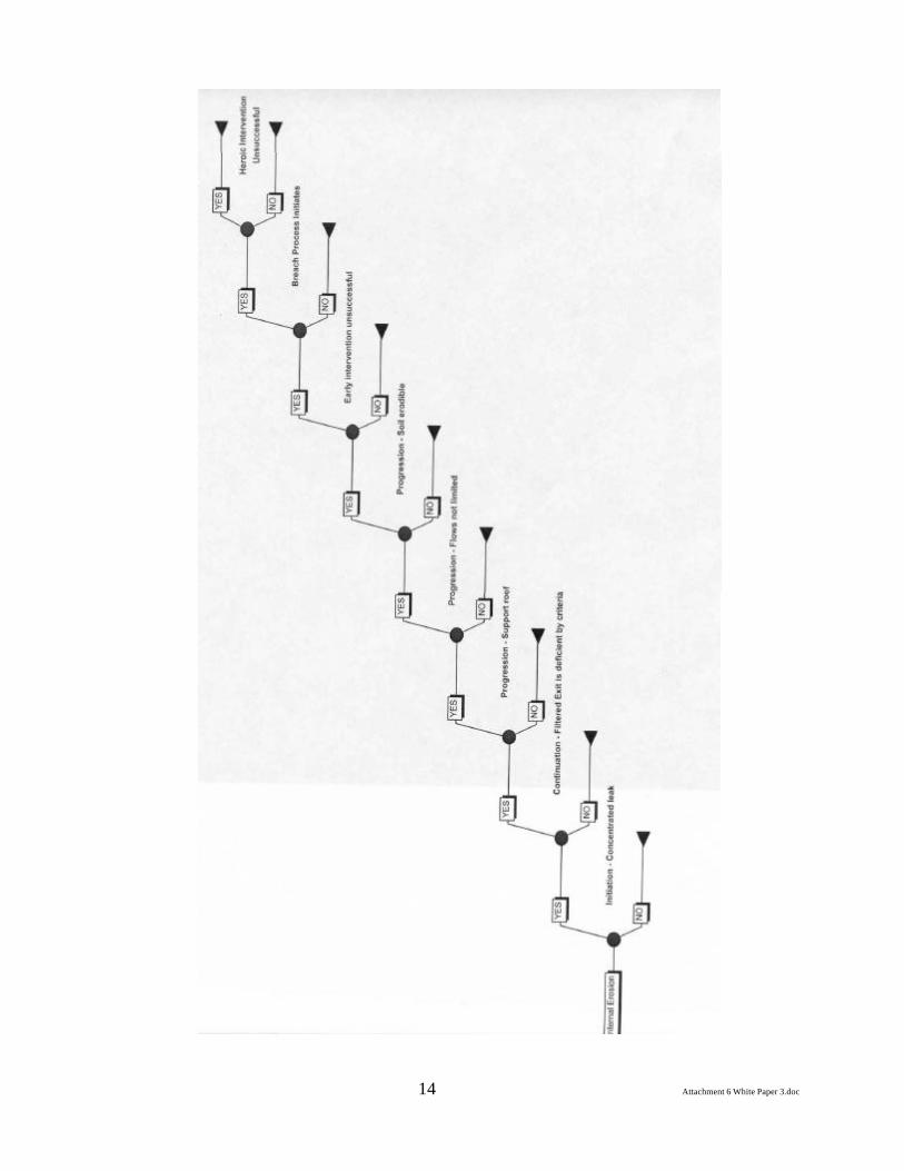
Attachment 6 White Paper 3.doc 14
White Paper on Investigation of Seepage Problems/Concerns at Dams, Including Use of Geophysical Techniques; and Instrumentation and
Measurements for Evaluation of Seepage Performance
INTRODUCTION
A basic principle of dam design is to provide as impervious a water barrier as feasible, satisfying safety and economic as well as technical requirements. Rims, abutments and foundations are integral parts of the water barrier.
Seepage through embankments, rims, abutments and foundations has been experienced by most dam owners. This paper presents what methods have been used to investigate and monitor this seepage.
Depending on the age, the design and construction records will vary greatly. A well designed and constructed dam will provide detailed information on the construction method and treatment and any known features in the foundation. A dam built with limited design may have little or no record of the construction or materials at the site.
To understand the seepage one must understand the stratigraphy of the area. There are various methods to determine the types of material and their condition at the site. They vary from drilling, sampling, and testing to more unique methods such as geophysical investigations.
A field investigation program should be set up to determine the stratigraphic and phreatic data. This data is required to perform a safety evaluation of the dam with respect to seepage or underseepage. If in the study it is proposed to perform a seepage analysis, a thorough understanding of the flow and phreatic conditions through the embankment, foundation, abutments and rims must be gained. A field investigation program should be designed with five main objectives in mind:
1. Augment already known data, 2. Assess the subsurface soil conditions, with particular emphasis on soil types, three-
dimensional stratigraphy, and engineering properties of the embankment, abutment and foundation.
3. Identify the depth, aerial extent and thickness of any artesian layers. 4. Obtain piezometric data over the entire site at a number of depths. 5. Install additional piezometers to better define seepage conditions and provide for long-
term, groundwater monitoring capabilities.
Investigation Methods:
Peizocone Penetration Test (CPTu) and Standard Penetration Test (SPT) can be performed to achieve the first three objectives. The CPTu test is a quick, efficient way to get quality piezometric and inferred soil property data with minimal site disturbance. SPT tests are used to verify blow counts and soil types interpreted from the CPTu results with those values obtained from the SPT test. The SPT holes also allow exploration of soil layers below the reach of the CPTu rig.
Push-type and standpipe piezometers can be installed along the crest, abutments, the downstream toe, and the valley floor to achieve the fourth objective of the program.
Below are the requirement and investigations performed at one of TVA’s projects.
Prepared by Charles D. Wagner, TVASeptember, 2000 Page 1 Attachment 7 White Paper 4.doc
White Paper on Investigation of Seepage Problems/Concerns at Dams, Including Use of Geophysical Techniques; and Instrumentation and
Measurements for Evaluation of Seepage Performance
1. CPTu Testing Procedure and Equipment
All CPTu tests and equipment were performed in accordance with ASTM Standard D3441-86. A cylindrical rod is hydraulically pushed at a rate of 4 ft/min into the soil. The rod has a conical tip 1.4 inches in diameter with a 60 degree tip angle. On the nonartesian holes, 1.4 inch drive rods were used. A 1.75-inch diameter friction reducer was used between the probe and the rods to obtain consistent readings. On artesian holes, 1.8-inch diameter rods were used with a 1.9-inch diameter friction reducer. All testing was performed using a 20 ton CPTu vehicle capable of a maximum 20 ton push and 30 ton pull.
All testing was performed using a Peizocone probe. A pressure transducer located just behind the tip made possible the measurement of pore water pressures during the test. Tip resistance, side friction and pore water pressure were measured at 2 cm intervals as the probe was pushed into the soil. These values, as well as depth, inclination and total pushing force, were recorded.
Permeabilities
• Dissipation Testing
Pore water pressures measured during penetration reflect the volume changes induced by the shearing and/or compaction effects of soil, therefore, dissipation tests had to be performed to measure hydrostatic pressures. Dissipation tests were performed at selected depths in specific holes by stopping the probe penetration and allowing the pore water pressures to dissipate. Pore water pressures were recorded at specific time intervals until there was no change over a one minute period. Each test was performed for a minimum of five minutes. The majority of the dissipation tests were performed at downstream locations in order to better understand the artesian conditions.
Preliminary estimates of permeabilities for the embankment fill and foundation material were based on the results of dissipation test performed during CPTu tests.
In this method, it was assumed that, under the given conditions, the cone penetration test was more accurately linked with the mechanics associated with a “Pipe-Cavity Test.” The rate of rise of the water in the tube is then transformed into soil conductivity by the use of the following equation developed by Luthin1:
Prepared by Charles D. Wagner, TVASeptember, 2000 Page 2 Attachment 7 White Paper 4.doc
White Paper on Investigation of Seepage Problems/Concerns at Dams, Including Use of Geophysical Techniques; and Instrumentation and
Measurements for Evaluation of Seepage Performance
k = pr2ln(Y1/Y2) / S(t2-t1)
where k is the hydraulic conductivity,Y1 the distance from the water table to water level in pipe at time t1,Y2 the distance from water table to water level in pipe at time t2,r the radius of the pipe,(t1-t2) the time for water level to change from Y1 to Y2, andS the shape factor coefficient
• Falling Head tests
A series of “falling head” tests were conducted in selected piezometers. The general procedures for the falling head test consisted of the following steps:
1. A clear plastic pipe approximately 6 feet in length was attached to the top of the existing piezometer standpipe. A tape measure was attached to the side of the clear plastic to allow readings during the test.
2. The pipe was filled to the top with water. The initial level was noted and a stop watch started. Readings were taken at regular intervals until the total drop in water level exceeded 5 feet, or the test duration exceeded 10 minutes.
At least 10 readings were recorded for each test. The following relationship, obtained from Hoek and Bray2, was used to compute the permeability coefficient, K:
k= A/ F(t2-t1) x ln(H1/H2)
where A is the cross section area of the water column F the shape factor which depends upon the conditions at the bottom of the hole
• Comparison of Field Test results to Empirical Values
Empirical values of permeability, based on grain size parameters Dmin, Dmax, and D10, were obtained from charts proposed by Hunt3 and Justin et al.4.
Backfilling Test Holes
Because of artesian conditions existent at the downstream valley, the following procedure was used to prevent seepage from the holes and avoid potential soil piping.
1. Installed standpipe at the surface around the rods. 2. Withdrew the rods slowly to minimize suction pressures and subsequent soil blow-up.
Generally, the holes tended to collapse at the top of the artesian sand layer. 3. Measured the ground water level and hole collapse immediately after the rods were
withdrawn. 4. Tremie grouted the holes through the standpipe before the truck was moved off the
hole. Applied a slight amount of air pressure at the top of the standpipe (less than 10 psi) to help the grout permeate through the collapsed soil.
Prepared by Charles D. Wagner, TVASeptember, 2000 Page 3 Attachment 7 White Paper 4.doc

White Paper on Investigation of Seepage Problems/Concerns at Dams, Including Use of Geophysical Techniques; and Instrumentation and
Measurements for Evaluation of Seepage Performance
Nonartesian holes were tremie grouted after 24 hours water levels had been measured. A 1:1 (by weight) water to portland cement mix with bentonite was found to give satisfactory results. Holes in which the grout had settled were topped with grout.
2. Standard Penetration Testing (SPT)
The location of these holes was chosen after the CPTu testing program was completed. The location was chosen based on the results of the CPTu test in order to correlate the CPTu to SPT. The CPTu is a quick and less costly approach to obtain information about the soil stratigraphic.
Testing Procedures and Equipment
The holes were advanced using a 5-inch wide fishtail bit under a head of bentonite drilling mud to ensure borehole stability. Side baffles on the fishtail bit directed the drilling mud upwards. As a result, water table measurements could not be directly taken. SPT tests were performed every 2.5 feet using a 2.00 in OD sampler. Blow counts were recorded for each 6 inches of penetration for a total of 18 inches. The testing procedure utilized a safety hammer actuated by the throw of a rope. The rope was wrapped one and one-quarter times around the cathead. Based on correlation’s with the CPT test, it is believed that this testing procedure delivers 60 percent of the maximum theoretically available energy, Seed et. al.
Backfilling Test Holes
The backfilling procedure consisted of:
1. Extracting all drilling equipment from the hole and keeping the hole filled with drilling mud.
2. Lowering a 2-inch diameter PVC tremie pipe to approximately 6 inches from the bottom of the borehole.
3. Attaching a funnel, 8 inches in diameter and 10 inches in length, to the upper end of the PVC pipe.
4. Grouting by gravity feed through the tremie pipe until the borehole was completely filled.
A 1:1 (by weight) water to portland cement mix with 1 percent bentonite was used to backfill the holes. Bentonite was added to the grout to increase mix stability by holding particles in suspension and minimize shrinkage.
3. Undisturbed Sampling and Laboratory Testing Program
A program of subsurface undisturbed sampling may be required, depending on the detail of any evaluation or analysis required for the dam and site. The details of a typical program is not including in this paper, but may be more suited for a paper on evaluation and analysis.
Prepared by Charles D. Wagner, TVASeptember, 2000 Page 4 Attachment 7 White Paper 4.doc
White Paper on Investigation of Seepage Problems/Concerns at Dams, Including Use of Geophysical Techniques; and Instrumentation and
Measurements for Evaluation of Seepage Performance
4. Geophysical Investigations
Geophysical investigations are conducted at sites to:
• Identify buried material • Determine the presence of contamination plumes, their distribution, direction, and rate
of movement • Characterize natural or manmade hydrogeologic conditions including water bearing
fractures • Locate leaks in dams • Stratigraphy • Locate subsurface caverns/voids that can develop into sinkholes
Geophysical testing such as surface surveys help to better interpret or explore the interiors of dams where intrusive methods, such as drilling would be expensive and/or not feasible due to physical constraints.
Geophysicists use theories and applications from physics to remotely measure physical properties, be it under the ground surface, under water, in the upper atmosphere, or within dams. Common techniques employed at dams include spontaneous potential methods, ground penetrating radar, and seismic velocity analysis.
Methods
Many different methods are used by the geophysicist. A description of those used most often during investigations, either singly or in combination.
• Ground Penetrating Radar (GPR)
GPR surveys are impulse systems that transmit short duration electromagnetic pulses into the ground from an antenna near the surface. These pulses are reflected from interfaces with contrasting electrical properties back to the receiver section of the antenna connection to the control unit for processing and display. Contrasts in electrical properties of material in the earth cause reflections of the radar signal. These reflection occur at different soil strata, soil/rock interfaces, rock/air interfaces (voids), fractures, manmade objects (drums, underground storage tanks, trenches, pits), or any interface that can create a contrast in the dielectric properties.
Digging a trench and filling it, for example, can create a difference between the dielectric properties of the disturbed earth and the undisturbed earth.
The distance to reflectors on GPR profiles is determined by the echo delay time. The time can be converted to apparent depth: 1) if the velocity of the radar pulse can be determined; 2) if an object is at a known depth, the depths can be extrapolated; 3) the hyperbolic geometry of echo curves can furnish an estimate of depth; and 4) common depth points sounding can determine pulse position and depth and have a strong dependence on the earth’s moisture content.
Prepared by Charles D. Wagner, TVASeptember, 2000 Page 5 Attachment 7 White Paper 4.doc
White Paper on Investigation of Seepage Problems/Concerns at Dams, Including Use of Geophysical Techniques; and Instrumentation and
Measurements for Evaluation of Seepage Performance
GPR profiles are continuous and repeatable during different times of the profiles. GPR produces digital data that can be processed and filtered to produce data enhancements for maximum penetration depth.
Compared to other geophysical techniques, GPR has a shallower exploration depth. GPR does not usually exceed 5 feet in clays, although it has recorded penetrations of over 100 feet in sands. GPR profiling depth is greatest in materials having a high resistivity, such as coarse sands or gravel; it cannot profile through salt water.
• Electromagnetic Induction (EM) Surveys
An EM survey can be used to detect conductivity anomalies, expected to occur above caverns or fractures zones in rock. The fractures and caverns provide the major flow paths in the rock, and monitor wells can be installed at these locations for remedial design. The geophysical surveys can also pinpoint fractures inferred from aerial photos.
The EM can also locate utilities and buried metal debris, in addition to nonmetallic burial such as trenches and pits.
EM equipment is portable and allows data to be collected as fast as the operator can walk. Subsurface conductivities (reciprocal resistivities) are collected rapidly and continuously as the operator surveys the site with the instrument. Investigations that effectively define the location and extent of potential problems areas at shallow depths can be performed rapidly. The principal value of the EM method is that it provides continuous, high resolution data at a very low cost.
The EM survey is usually conducted using an induction meter. The EM measures the apparent conductivity of the subsurface using the principles of electromagnetic induction. The EM consists of two horizontal coplanar loops, one acting as a transmitter and the other as a receiver. The transmitter induces eddy currents in the earth, which in turn produce a secondary field. The receiver intercepts the secondary field in which the EM measures the terrain conductivity by comparing the strength of the secondary field to that of the primary.
The depth of investigation by EM is a function of the intercoil spacing and the orientation of the antenna dipoles. The EM with an intercoil spacing of 12 feet and used horizontal mode, has an effective depth of analysis of approximately 20 feet. The EM with intercoil spacing of 10, 20, and 40 meters and used in the horizontal mode, has a maximum depths of analysis of approximately 45, 90, and 180 feet.
Very Low Frequencies (VLF)
VLF surveys can locate water-bearing fractures to assist in monitor well installation for remedial investigations. This method is particularly well suited for fractures in crystalline rocks.
VLF is commonly conducted using a VLF meter, which uses EM fields to locate fractures. The VLF meter uses the magnetic components of the electromagnetic field generated by
Prepared by Charles D. Wagner, TVASeptember, 2000 Page 6 Attachment 7 White Paper 4.doc
White Paper on Investigation of Seepage Problems/Concerns at Dams, Including Use of Geophysical Techniques; and Instrumentation and
Measurements for Evaluation of Seepage Performance
long-distance radio transmitters in the VLF band. The transmitters are used for long-distance communication between Naval stations.
• Resistivity
The resistivity method measures the electrical resistivity of the subsurface that includes soil, rock, and groundwater. Resistivity provides information on layering and depths of subsurface strata including lateral changes in the surfaces. Risistivity can locate water-saturated and unsaturated voids, leaking dams, and map stratigraphic and structural features.
Resistivity surveys can be conducted across a total survey area, as a profile, or as soundings at discrete locations. A current is inserted into the ground by a pair of surface electrodes. The subsurface resistivity is calculated from the electrode separation, applied current, and measured voltage. Most soil and rock minerals are electrical insulators (high resistivity), and current flow is conducted primarily through the moisture-filled pore spaces within the medium. The resistivity of porous media is largely controlled by the amount of pore water, porosity and permeability of the porous media, and the dissolved solids concentration of the pore water.
• Seismic Refraction
Seismic refraction measures density, thickness, and depth of geological strata using sound (acoustic) waves transmitted into the subsurface. Sound waves travel at different velocities in various soils and rocks and are reflected at the interface between layers. The time is measured from the time source to geophones. The seismic source for shallow investigations range from a hammer striking a metal plate to plastic explosives. Geophones receive the vibration of the sound energy and translate it to an electric signal. The signal is displayed on a seismograph. Time versus distance plots of the first-arrival are used to locate depth of strata and possible fractures.
The seismic refraction method is based on three important assumptions:
1. Acoustic velocity generally increases with depth 2. A sufficient acoustic velocity contrast exists between layers to allow differentiating
between adjacent strata of interest 3. The layer has sufficient thickness to permit detection
If these assumptions are not reasonably satisfied at a specific site, this technique may provide little usable data or interpretation may become quite involved and expensive.
Prepared by Charles D. Wagner, TVASeptember, 2000 Page 7 Attachment 7 White Paper 4.doc
White Paper on Investigation of Seepage Problems/Concerns at Dams, Including Use of Geophysical Techniques; and Instrumentation and
Measurements for Evaluation of Seepage Performance
5. Monitoring
Piezometric Measurements
Piezometric measurement locations should be chosen to give a better understanding of the seepage pattern through the abutment, foundation or embankment. Piezometers are installed for various purposes. The main two reasons are to determine the phreatic head in the embankment the other main reason is to determine the pore pressure in a particular layer.
Piezometers have been installed to monitor seepage before, during and after remedial measures to determine the effectiveness of the grouting.
Dye Testing
Drilling holes to inject dye for dye testing to determine flow path is sometime used.
Weir Measurements
Weir measurements are normally taken to monitor any change in the leakage. Seepage amounts are usually influenced by headwater level, seasonal and the loss of material, such as clay seams.
These measurements are typically taken at toe drains, springs and other seepage paths.
Water Quality Tests
Water quality tests are performed to determine the presence of solids in the runoff from drains. These results can be compare to the various material at the site to determine the possible origin.
Grout Monitoring
Real-time performance monitoring used during grouting includes results from drilling, water tests, calculation of grout hole reduction ratios, and dye testing. This monitoring allows onsite engineers to track the development of the integrity of the grout curtain and focus grouting efforts on specific zones along the grout rows. Also, the results of the grouting can be demonstrated from data monitored for 1) discharge from rim leak; 2) groundwater elevations down-gradient from the grout curtain; and 3) headwater elevation.
Prepared by Charles D. Wagner, TVASeptember, 2000 Page 8 Attachment 7 White Paper 4.doc
White Paper on Investigation of Seepage Problems/Concerns at Dams, Including Use of Geophysical Techniques; and Instrumentation and
Measurements for Evaluation of Seepage Performance
1. Luthin, J. N., “Drainage Engineering,” Published by John Wiley and Sons, New York, 1966.
2. Hoek, E., and Bray, J. W., “Rock Slope Engineering,” Institute of Mining and Metallurgy, London, 1981.
3. Hunt, R. E., “Geotechnical Engineering Investigation Manual,” McGraw-Hill Series in Geotechnical Engineering, McGraw-Hill Book Company, New York, 1984.
4. Creager, W. P., Justin, J. D., and Hinds, J., “Engineering for Dams - Vol. III: Earth, Rockfill, Steel and Timber Dams,” John Wiley and Sons, New York, 1945.
Prepared by Charles D. Wagner, TVASeptember, 2000 Page 9 Attachment 7 White Paper 4.doc
5.0 REMEDIATION OF SEEPAGE PROBLEMS THROUGH CUTOFF OR REDUCTION OF FLOW AND THROUGH
COLLECTION AND CONTROL OF SEEPAGE INCLUDING THE USE OF GEOSYNTHETICS
WHITE PAPER FOR THE ASDSO SEEPAGE WORKSHOP, OCTOBER 17-19, 2000 - DENVER
James R. Talbot, Steve J. Poulos, and Ronald C. Hirschfeld
October 2, 2000
5.1 INTRODUCTION
5.1.1 Types of Seepage Problems
The two principal problems associated with seepage through earth dams, their foundations, and their abutments are:
1. Piping 2. Excessive water loss
Remedial measures for preventing piping are aimed at controlling seepage so that the seepage does not cause internal erosion of soil from the embankment, foundation, or abutments of a dam. Remedial measures for preventing piping may not reduce the rate of seepage and often increase the rate of seepage.
Remedial measures for reducing water loss are aimed at reducing seepage through the embankment, foundation, and abutments. Although such measures may reduce the pressures and the rate of water flow through a dam, its foundation or abutments, it is nevertheless vital to install proper drainage systems on the downstream side of the dam as the primary line of defense against piping.
5.1.2 Recognizing and Correcting Seepage Problems
The following sequence of activity is commonly followed in connection with a correcting a seepage problem in a dam:
1. Field observations indicate that there may be a seepage problem. 2. Information is gathered to determine the cause of the problem. 3. Remedial measures are designed. 4. Remedial construction is carried out. 5. Observations of the effectiveness of the repairs are made.
The steps followed in the above sequence are discussed briefly in Sections 5.1.3-7.
Attachment 8 White Paper 5.doc
5.1.3 Field Observations That Indicate Seepage Problems
1. Piping Problems
a. Springs discharging muddy water or clear water on the downstream side of the dam, abutments or downstream valley slopes, through minor geologic details in the foundation and abutments, cracks in the embankment, compacted layers that are more pervious than their neighbors, animal burrows, roots or root holes near live or dead trees, and near uprooted trees.
b. Muddy or clear water flowing next to structures (such as spillways and low-level outlet pipes) that penetrate the embankment, foundation, or abutments.
c. Muddy water discharging from spillways or low-level outlet pipes at times when the water in the reservoir is clear.
d. Muddy water or water carrying silts or sands discharging from drains (including relief wells) in the embankment, foundation, or abutments.
e. Depressions or sinkholes anywhere on the embankment or near the embankment on either the upstream side or downstream side of the dam.
f. Increasing or decreasing flow in drains with constant reservoir level.
2. Excessive Water Loss
Excessive water loss may occur through the embankment, foundation, or abutments without any visible evidence of seepage. Such excessive water loss might only be detectable as a visible or measurable drop in the reservoir level when the outlet is closed and the weather is dry. Such losses of water are not important if there is little value to the water. However, if the water is being used for recreation, power, or potable water, the value of the water may be sufficient to investigate and perhaps remediate the cause, even though there is no other evidence that there may be a piping problem.
5.1.4 Information Needed to Determine the Cause of the Problem
1. Piping
If the cause of a piping problem can be identified, more-effective remedial measures can be designed. Some field observations of a piping or potential piping problem may give an indication of the cause of the problem—for example, water flowing next to a structure that penetrates the dam; deteriorated pipes that penetrate the embankment, foundation, or abutments; uprooted trees. Other field observations of a piping or potential piping problem may give limited or no indication of the cause of the problem—for example, springs on the downstream side of the dam; muddy water discharging from drains. If the field observations do not indicate a specific cause of piping, the cause may be a minor geologic detail in the foundation or abutments or a minor detail of construction.
The designer of remedial measures against piping should always examine the detailed record of the design and construction of the dam to look for those “minor” details that could be a cause of piping. Field investigations (such as
Attachment 8 White Paper 5.doc
borings and pore-pressure measurements) are likely to be of limited or no value because they are likely to be ineffective in uncovering the critical “minor” details.
2. Excessive Water Loss
Usually, there will be no visible evidence of excessive water loss that can be used for determining the cause. The designer of remedial measures to reduce water loss must review the design studies made for construction of the dam, field records of the construction, and available records of observations made throughout the life of the dam to determine, if possible, the cause(s) of the excessive water loss. Because excessive water loss is a function of the overall character (not the minor details) of the embankment, foundation, and abutments, a field investigation will likely be effective for determining the cause(s) and designing remedial measures.
5.1.5 Design of Remedial Measures
The design of remedial measures is the subject of subsequent sections of this paper.
5.1.6 Remedial Work
During remedial work, the designer must observe the details of the embankment, foundation, and abutment that are revealed by the construction activity, because even the most detailed field investigations that are made to design the remedial measures cannot possibly reveal all the details that may be critical to the effectiveness of the remedial measures.
5.1.7 Observations After Remedial Work Is Completed
Because it is so difficult to be sure that remedial measures address all the causes of a seepage problem, it is essential that field observations be made after remedial work is completed to determine whether the remedial measures are effective.
5.2 COLLECTION AND CONTROL OF SEEPAGE
5.2.1 Seepage Control
The addition of downstream drainage is usually the best solution for seepage problems in dams. Several types or methods of drainage have been successfully used for various seepage conditions. These methods with their advantages and disadvantages are:
1. Adding an embankment (chimney) drain to the dam by removing the downstream slope to a sloping surface and constructing a filter-drain on the slope while replacing the downstream section1. A collection system is usually also added in the form of an excavated foundation drain under the downstream shell of the dam.
a. Applicable condition – Wet areas or springs on the downstream slope
1Brodhead Dam, Pennsylvania, reported by Talbot and Ralston, 1985
Attachment 8 White Paper 5.doc
from seepage through permeable layers in the dam, or from cracks or other anomalies in the dam. Stability problems on the downstream slope caused by seepage.
b. Advantages – Drain intercepts all cracks or other anomalies and permeable layers inside the dam where the drain can be confined and protected. Protects against development of concentrated leaks in cracks and solves stability problems.
c. Disadvantages – The reservoir is usually drained for stability. Must have a high-capacity outlet to avoid reservoir filling if a flood occurs during rehabilitation construction. Is major construction and very expensive.
2. Add an embankment (chimney) drain to dam by constructing a filter-drainage zone on the downstream slope of the existing dam and a new shell zone to cover the drain and form a new downstream slope. The conditions for installing this feature are the same as previous.
a. Advantages – Intercepts all cracks or other anomalies and permeable layers in the dam. Protects against development of concentrated leaks in cracks and solves stability problems. Reservoir may not have to be drained to construct it.
b. Disadvantages – Requires larger footprint (property) for the dam. Additional shell zone material must be available.
In all cases where an embankment chimney drain is added to the downstream section of the dam, the dam must be designed against slope failure and uplift or blow-off of the downstream drain and shell zone with full head of the reservoir at the upstream face of the filter.
3. Add an embankment (chimney) drain to the dam by trenching into the dam from the crest using a trenching machine. The trench is filled with filter material and outlets are constructed by trenching to the downstream toe periodically. This solution has been used for dry flood control dams where cracking has been a problem. 2
a. Applicable condition – Mainly used for repairing small, dry flood-control dams where cracking has occurred and the dam had no embankment drain. It could possibly be used where the reservoir was drained for some time to allow the dam to dry sufficiently that a trench will remain open for filter placement.
b. Advantages – A chimney drain can be installed inside the dam to protect against the development of concentrated leaks. It is relatively simple and inexpensive.
c. Disadvantages – The dam must be dry so that the excavated trench will be stable. If the dam is higher than trenching machines can excavate, the top of the dam must be removed if the drain is to reach the foundation level.
4. Provide additional downstream drainage using toe drains – A toe drain may be excavated at the downstream toe. The drain should extend to the depth of the
2Flood Control Dams in Arizona, reported by Talbot and Deal, 1993
Attachment 8 White Paper 5.doc
highly permeable layers in the foundation (taking care that the reservoir is down or that a contingency plan is in place to prevent a piping failure) and should intercept the contact between the foundation and embankment, if possible. A berm is often placed over the drain for additional stability, particularly if the drain is constructed beyond the toe of the dam. The drain should consist of filter and drainfill zones, and may include collection pipes to carry seepage to a safe outlet.
a. Applicable conditions – Wet areas, ponding or running water, sand boils, or springs at the toe of the dam from seepage through the foundation or abutments in permeable layers, cracks, or other anomalies.
b. Advantages – Can be installed with minimum disturbance to the dam. It is best to drain the reservoir, however; they have been installed without draining the reservoir when stability has not been a problem.
c. Disadvantages – The reservoir may have to be drained to provide stability during excavation and installation. Drains usually require continued maintenance and rejuvenation
5. Cleaning of existing clogged drains. High-pressure cleaning using jet sprayers run through the drain pipe from the outlet have been partially successful for cleaning drains clogged with slimes or algae.3 Reaming tools are used for removing roots.
a. Applicable conditions – A common drain-clogging agent is iron-bacteria slime or other slimes associated with manganese or sulfur deposits. Algae or root growth may also be involved in drain clogging. For all of these problems, the effectiveness of the drain diminishes with time and the drain may eventually become completely ineffective.
b. Advantages – Some drainage can be restored without draining the reservoir or requiring major design and construction.
c. Disadvantages – Drain cleaning usually never completely restores the drain operation back to its original capacity or to the design intent. Cleaning is not a permanent solution and unless the source of the problem is resolved, the drains will continue to clog.
6. Install a downstream blanket drain – Blanket drains are usually thin layers of filter material and/or drainfill placed on the foundation and are often used in conjunction with other drains such as an embankment drain or toe drain. They may serve as an outlet for other drains and to intercept seepage returning to the surface of the foundation under the downstream toe of the dam. They must be covered with the downstream shell of the dam or a berm extending downstream from the dam to confine the drain material and provide stability against uplift.
3Ford, Harry (date unknown, reprinted January 1993). “Iron Ochre and Related Sludge Deposits in Subsurface Drain Lines” (Circular 671), Florida Extension Service. Http://edis.ifas.ufl.edu/BODY_AE026.
Attachment 8 White Paper 5.doc
a. Applicable conditions – Wet areas, ponding or running water, sand boils, or springs at the toe of the dam from seepage through the foundation in permeable layers, cracks, or other anomalies. An excavated toe drain is best for these conditions, but a blanket drain may be used when an excavated trench is not possible or practical.
b. Advantages – Can be installed without draining the reservoir when a berm is constructed over the blanket downstream. Can be used when stability or other problems prevent excavating a toe drain trench.
c. Disadvantages – Does not reduce uplift pressures under the dam. Requires a larger footprint (more space) for the dam.
7. Addition of downstream relief wells – Relief wells are drilled into the foundation, the downstream face, or the abutments. Relief wells may be filled with drainfill materials or have a casing inserted with well screens to allow the collection of seepage water at a predetermined level. Relief wells may be added to provide additional capacity to an existing drainage system or to solve stability problems caused by uplift pressures.
a. Applicable conditions – Relief wells are appropriate if artesian pressure exists in layers deeper than is practical for using other drains such as an excavated toe drain.
Under no circumstances should holes or trenches be dug on the downstream side of a dam with water in the reservoir, unless a well-thought-out contingency plan is in place to prevent runaway erosion into the opening.
b. Advantages – Usually can be installed without draining the reservoir.
c. Disadvantages – Are somewhat limited in capacity and effectiveness. Require considerable maintenance.
8. Relief well cleaning – See white paper by Mr. McCook.
5.3 METHODS FOR REDUCING SEEPAGE THROUGH EMBANKMENT DAMS
5.3.1 Introduction
In this paper we cover cutoffs and other flow reduction techniques for existing embankment dams. Many of these techniques can be used for new dams.
Proper downstream drainage collection and safe discharge must always accompany any flow-reduction technique.
Reduction of seepage through dams has the following objectives:
1. Save water as a resource. 2. Reduce seepage pressures within the dam, its foundation and abutment, and at the
downstream toe area, thus reducing to some extent the probability of piping failure.
3. Reduce the required size of seepage-control systems.
Attachment 8 White Paper 5.doc
.5.3.2 Alternatives for Reducing Seepage
1. Upstream blanket
2. “Cutoff” on upstream face of dam, abutments and foundation
3. “Cutoff” within dam, abutments and foundation
5.3.3 Upstream Blanket
1. Composition: Upstream blankets can be constructed of low-permeability soils or artificial impervious barriers such as asphalt, soil cement, roller-compacted concrete and concrete. The blankets must be properly filtered at the bottom to prevent piping through the blanket and subsequent loss of water. Even relatively small flows can substantially increase the water pressures within the dam, foundation and abutments.
2. Advantages: Can be low cost. Can be placed through water in reservoir. Reduces flow so that seepage pressures in the dam and abutments are reduced, with the result that the likelihood of piping can be reduced and the stability of the dam may be improved through reduction of water pressures in the dam, foundation and abutments. In particular, upward gradients at the downstream toe are reduced and can be reduced below levels that are of concern.
3. Disadvantages: May require draining of reservoir. May need to cover large areas and the cost can be great. Can be difficult to place through reservoir so that the blanket is continuous. Difficult to judge how far upstream to carry the blanket, since water may bypass blanket anywhere upstream. Must be tied into the upstream cutoff. Can not be tied into existing internal cutoff.
5.3.4 “Cutoff” on Upstream Face
The term “cutoff” is in quotations because almost no technique used for this purpose will actually cut off water flow. There always will be leakage that must be safely collected and drained on the downstream side of the cutoff.
1. Composition: Cutoffs on the upstream face may be composed of compacted impervious soil, soil and bentonite mixtures, soil cement, roller-compacted concrete, concrete, asphalt, and, rarely, metal or masonry.
2. Advantages: Reduces water flow on the upstream side and therefore reduces seepage to be collected and drained downstream and reduces pressures within the dam, abutments and foundation. Is accessible for repair from the upstream face by lowering the reservoir.
3. Disadvantages: Must be protected against wave action. Settlement of the dam can cause cracking of the more rigid upstream cutoffs, such as asphalt and concrete. Even a compacted soil blanket may crack due to differential settlements. Frost action can cause deterioration of the upstream cutoff. Soil cutoffs that have dried may develop incipient cracks that may become passages for substantial leakage or piping if the water level rises rapidly. Water can bypass
Attachment 8 White Paper 5.doc
cutoff if the cutoff is not extended far enough into abutments. An upstream cutoff must be accompanied by systems that cut off or control flow through the foundation and abutments.
5.3.5 Internal “Cutoffs” within Dam
1. Composition: Internal cutoffs may be composed of concrete, soil-bentonite mixtures, sheet piles of wood or steel, or grout.
2. Advantages: Usually can be extended easily to cut off foundation and abutments using less material than would be needed for upstream cutoffs or blankets. Thick cutoffs are preferable to help avoid difficulties with obstructions during installation. Such cutoffs composed of concrete in a slurry trench can be used to go deep into the foundations. Some have extended over 200 ft into the foundation. Internal cutoffs are protected from damage by frost action. They can act as erosion-control barriers to limit damage when a dam is overtopped.
3. Disadvantages: If the cutoff begins to leak in the future due to movements of the dam or deterioration of the materials or poor construction of the cutoff, access to find the leak is very difficult if not impossible. Grout curtains injected to cut off seepage through a rock foundation can induce high pressures and cracking of the dam itself. Unless multiple rows (at least three) of grout holes are used at close spacing, cutoff is difficult to achieve. The pressures used must be low to avoid hydraulically fracturing the dam. Cutoff must penetrate through obstructions in the dam or foundation. These obstructions, if not handled properly can lead to future leakage. Sheet piles of wood or steel are particularly susceptible to difficulties with obstructions, which often cannot be felt during construction and which may open the joints or otherwise damage the sheeting.
5.4 PRECAUTIONS REGARDING USE OF GEOSYNTHETICS
5.4.1 Geomembranes
Geomembranes have been used for blanketing or providing seepage barriers in reservoirs.4 The main precaution for their use is that they may be vulnerable to puncture during installation or from animal traffic on them after they are installed. Proper thickness and strength of the membrane material is important, along with proper bedding preparation and cover over the membrane. The constant application of stress by individual soil grains on plastics can make them age at substantially increased rates than would be the case for an unstressed plastic. In addition, it is important to design for the lower friction angle that usually applies at the interface between the soil and membrane. Pore pressures also may build up at this interface if the soil is impervious.
5.4.2 Geotextiles as Filters in Dams
4For example, Mt. Elbert Forebay of the Fryingpan-Arkansas Project, U.S. Bureau of Reclamation. See http://www.gp.usbr.gov/co/fryarkpf.htm.
Attachment 8 White Paper 5.doc
There are two major problems with using geotextiles as filters in dams. These problems may possibly be overcome or proven as no problem with research, but until the research
is completed, the use of geotextiles as filters should be avoided in dams. 1. Tearing from movements in the dam – The major cause of cracking in earth
embankment dams is differential settlement of the foundation or the embankment soils. The areas over abutments or where the height of the dam changes abruptly are the most vulnerable. The main reason for installing filters in dams is to intercept all cracks. If the fabric tears in the plane of the crack, it will not serve to intercept the crack or as a filter in the plane of the crack. Tearing with movements in the dam is likely because:
a. The geotextile is very thin and will have a very large soil pressure on each side of it when installed in a dam. The soil pressure will pinch the fabric together from both sides and when movements occur that cause a crack in the dam perpendicular to the plane of the fabric, the geotextile will undergo stretching by several thousand percent over a short distance, which will tear the fabric.
b. Most dams are constructed of soils that contain rocks or rock fragments that are sharp and irregularly shaped. Normal construction practices are likely to tear the fabric, unless a substantial bedding (such as a sand layer of sufficient thickness) or other protective layer is placed next to the geotextile.
2. Inability of the geotextile to support the seepage discharge face – We hypothesize that sand filters function differently from geotextiles where they contact with the soil in the dam. The following items explain these differences:
a. Sand filters placed against a seepage discharge face such as the side of a drain trench flow to the soil face and apply a positive pressure to it. The sand particles provide a point of contact with the soil face and the distance between the points of contact are determined by the gradation of the sand. Research has shown that when certain filter gradation criteria are met, the soil particles will not move for high gradients and when water is passing through the soil (not a crack).5
b. A fabric by itself does not apply a pressure to the seepage discharge face, but is dependent on a material on the other side of the fabric to hold it against the discharge face. If the material on the other side of the fabric is gravel or stone as in most drainage or transition zones, then the contact points where the fabric is held against the discharge face are quite far apart compared to sand. The fabric may be loose and actually bulge away from the soil between the contact points. Research has shown that when a space is left between the filter and the soil discharge face, soil particles will move and the filter will clog. If sand must be used on the other side of a fabric so it will work properly as a filter, then the sand can provide the filter function by itself and the fabric is not needed.
c. Research is needed to check this hypothesis using testing conditions that simulate various conditions for using geotextiles as filters in dams.
5Research by U. S. Soil Conservation Service, reported by Sherard, et. all, 1984, 1989.
Attachment 8 White Paper 5.doc
5.5 REFERENCES
1. Ford, Harry (date unknown, reprinted January 1993). “Iron Ochre and Related Sludge Deposits in Subsurface Drain Lines” (Circular 671), Florida Extension Service. Http://edis.ifas.ufl.edu/BODY_AE026.
2. Hirschfeld, Ronald C. (1995). “Design, Construction, and Inspection of Embankment Dams to Reduce the Risk of Piping,” ICODS Technical Seminar: Seepage, Piping and Remedial Measures, Federal Emergency Management Agency, March 23-24.
3. Hirschfeld, Ronald C. (1999). “Overview of Geotechnical Aspects of Embankment-Dam Design,” Embankment-Dam Seminar, sponsored by Tennessee Valley Authority, Chattanooga, January 19–21.
4. Sherard, J. L., and Dunnigan, L. P. (1989). “Critical Filters for Impervious Soils,” Journal of Geotechnical Engineering, ASCE, vol. 115, no. 7, pp. 927–947.
5. Sherard, J. L., Dunnigan, L. P., and Talbot, J. R.(1984). “Basic Properties of Sand and Gravel Filters,” Journal of Geotechnical Engineering, ASCE, vol. 110, no. 6, pp. 684–700.
6. Sherard, J. L., Dunnigan, L. P., and Talbot, J. R.(1984). “Filters for Silts and Clays,” Journal of Geotechnical Engineering, ASCE, vol. 110, no. 6, pp. 701–718.
7. Talbot, J. R., and Deal, C. E. (1993). “Rehabilitation of Cracked Embankment Dams,” Geotechnical Practice in Dam Rehabilitation (proceedings of specialty conference sponsored by Geotechnical Engineering Division, ASCE; L. R. Anderson, ed.), Raleigh, N.C., pp, 267–283.
8. Talbot, J. R., and Ralston, D. C. (1985). “Earth Dam Seepage Control, SCS Experience,” Seepage and Leakage from Dams and Impoundments (proceedings of symposium sponsored by Geotechnical Engineering Division, ASCE; R. L. Volpe and W. E. Kelly, eds.), Denver, Col., pp. 44–65.
Attachment 8 White Paper 5.doc

White Paper on the Impacts of aging of seepage control/collection system components on seepage performance
I. Introduction
This paper discusses the components commonly included in drainage systems for embankments and dams and the mechanisms of aging that may impact their performance. The paper also discusses remedial alternatives.
II. How Drainage Components May Deteriorate
The components of a drainage system may deteriorate or become damaged from external forces including physical, chemical, and biological activity. Some of the ways that components become damaged are:
A. Material deterioration
1. Deterioration of clay pipes – Pipes may collapse and spread. Then, infiltration of soil into joints of clay tiles can occur.
2. Corrosion of corrugated metal pipe – outlet pipes where they are exposed to atmosphere.
3. Deterioration of wooden well screens in relief wells.
4. Changes in properties of the granular filters and drains in a system, or in a geotextile component of the system. Most common changes are siltation and cementation of the granular materials.
B. Mineralization (encrustation). Groundwater high in dissolved salts can contribute to clogging of well screens, perforations in drainpipes, and possibly to geotextiles. This process can also contribute to cementation of granular media in drains. Cementation of well screens and perforations causes reduced capacity. Cementation of granular media can cause loss of self-healing properties. The USBR Ground Water Manual 6 lists the most common forms of mineral encrustation in wells as:
1. Precipitation of iron and calcium carbonates as hard, brittle, cement-like material adhering to the well screens and also cementing the gravel pack or aquifer away from the screen.
2. Accumulation of iron and manganese hydroxides or hydrated oxides on the screen or in the formation next to it. The hydroxides are insoluble, jelly-like masses unless oxygen is present. If oxygen is present, the minerals oxidize into black, brown, or reddish granules.
3. Decomposition of lignite beds can result in formation of a slimy black or brown viscous material about the screen and in the adjacent aquifer.
6 United States Bureau of Reclamation. Ground Water Manual. Government Printing Office Stock No. 024-003-00179-1. Second Edition. 1995.
Prepared by Danny K. McCook, NRCS September, 2000 Page 20 Attachment 9 White Paper 6.doc
White Paper on the Impacts of aging of seepage control/collection system components on seepage performance
C. Bacterial. Several types of sludge deposits that are associated with bacterial activity can be a problem in drainage systems. The types of deposits may be classified as ochre, manganese deposits, sulfur slime, and iron sulfide. 7 Ochre deposits and associated slimes are usually red, yellow, or tan. Ochre is filamentous, amorphous, and is a sticky mass combined with an organic matrix that can clog slots, filter media, including geotextiles, and well screens. The iron ochre problem is probably the most serious deterioration problem associated with drainage systems because it is so widespread. The National Water Well Association has a slide presentation 8 and a report on the problem is included as Appendix A to the REMR report 9. Testing groundwater samples may indicate the potential for the problem to develop. 10
D. Cementation of filter media. Experience with volcanic sands in chimney drains in New Mexico demonstrates that aging and some type of chemical reaction of the sands leads to a loss of self-healing characteristics in the sands.11
E. Siltation of gravel packs where the well development was inadequate.
F. Damage to systems from repeated maintenance activity. Fittings become loose during surging, and subsequent maintenance procedures further damage the system until repairs are necessary.
G. Vandalism, especially to outlet pipes and other exposed components.
H. Impact of vegetation – penetration of roots into drain materials and pipes.
III. Components subject to aging
A. Granular filter/drain materials – sand and gravel. Experience with volcanic sands in chimney drains in New Mexico demonstrates that aging and a chemical reaction of the sands and groundwater leads to cementation and a loss of self-healing characteristics in the sands. Siltation and iron ochre deposits in well screen filter packs is also a type of deteriorated behavior.
7 Ford, Harry, Florida Extension Service. ”Iron Ochre and Related Sludge Deposits in Subsurface Drain Lines.” Circular 671, reprinted January l993. http://edis.ifas.ufl.edu/BODY_AE026. 8 National Ground Water Association. “Iron Bacteria, Sulfur Bacteria, and Water Well Maintenance,” 60 slides/notes and handout. Ref # A108 $126.50 9 "Proceedings of REMR Workshop on Research Priorities for Drainage System and Relief Well Problems." July, 1989. Compiled by R. E. Leach and H. M. Taylor, Jr., US Army Engineer Waterways Experiment Station, Vicksburg, MS.
Ford, ibid 11 Communication with Greg Cunningham, SCE, NRCS, Albuquerque, New Mexico
Prepared by Danny K. McCook, NRCS September, 2000 Page 21 Attachment 9 White Paper 6.doc
10
White Paper on the Impacts of aging of seepage control/collection system components on seepage performance
B. Pipes, excluding well screens and casing. These components may become damaged from external forces such as equipment crushing the pipes after installation. A paper presented at the ASDSO annual meeting detailed this problem at a Bureau of Reclamation Embankment. 12 Repeated maintenance activities in the case of relief wells can also damage the pipes by the extreme forces applied in surging the wells. Iron ochre clogging of perforations or slots in drainpipe is another common problem. Another problem is ultraviolet light attack of exposed pipes. Types of pipes affected include:
1. Asbestos cement
2. PVC and HDPE – may be particularly susceptible to damage from surging in relief wells.
3. Clay tile pipe
4. Concrete bell and spigot
5. Corrugated metal pipe – especially susceptible to corrosion damage. This could lead to piping of surrounding filter media and crushing of the pipe.
C. Well screens – in one of the reports in the REMR document, PVC pipe is listed as inferior to stainless steel because it is not as robust and resistant to damage from cleaning activities such as surging. The Author became familiar with the damage to relief well plumbing systems in a study of an embankment in Minnesota. The relief wells were replaced with a deep trench drain because the repeated maintenance was costly and damaging to the system. Chemical applied to relief wells may also contribute to corrosion of the pipes and screens in the wells. Various materials have been used for well screen material including the following:
1. Wooden staves
2. Stainless steel
3. Brass
4. PVC or other plastic pipe used for screens
D. Fittings – elbows, tees, etc. Loosening caused by physical movements, loadings, repeated surging in the case of relief wells.
E. Geosynthetics
1. Loss of capacity due to silt plugging
2. Loss of capacity due to ochre buildup or other biological plugging. 13
The potential is probably more problematic for non-woven geotextile
12 Pabst, Mark. U.S. Bureau of Reclamation. “Ochoco Dam Drain Rehabilitation, ” ASDSO Annual Meeting, St. Louis, MO. October 10-13, 1999 13 Mackey, R.E. and G.R. Koerner. “Biological Clogging of Geotextile Filters- A Five Year Study,”Geosynthetics 99, Proceedings. International Fabrics Association International.
Prepared by Danny K. McCook, NRCS September, 2000 Page 22 Attachment 9 White Paper 6.doc
White Paper on the Impacts of aging of seepage control/collection system components on seepage performance
than for woven.
IV. Consequences of deterioration. When drainage system components deteriorate, the system collects seepage less efficiently. Consequently, pressures build up above those for which concrete structures or earth blankets were designed. Another problem occurs when seepage systems develop cracks or other larger openings and lose their filtering capability. Then, the surrounding granular filter media or foundation soils can pipe into the seepage control system. As with any piping scenario, continued piping can develop into failures.
A. Reduced flow capacity due to decreased cross-sectional area. Buildup of iron ochre in the filter media and in the screens of relief wells is probably the most common mode of deterioration in drainage systems. The buildup causes increased uplift pressures on clay blankets or concrete structures being protected by the wells. Sand boils may develop that were formerly controlled, and a rise in piezometric levels for a given reservoir elevation usually accompanies the decrease in well capacities.
B. Leaks in system – piping. When drainage conduits are damaged by maintenance activity, subsequent surging pressures can wash out around the defects and erode annulus soil and drain fill around the pipes. Piping of surrounding filter media and soil can also occur when drainage conduits are damaged from corrosion, collapse from loading, separation from consolidation, and other mechanisms. Sinkholes are the ground or embankment surface are common manifestations of subterranean piping.
C. Increased pore pressures caused by decreased capacity. This can occur most commonly in relief wells, but can also occur in deep trench drains where iron ochre buildup is severe. The result of increased pore pressures in the foundation may be sand boils developing and uplift pressures increasing under concrete appurtenances.
D. Siltation of filters and slotted pipes or well screens can occur when poor check valves allow backwater into the system. This can reduce the flow capacity of the system and lessen the benefits of pressure relief.
V. Relief well maintenance problems. In the REMR report 14, a number of relief well problems were identified as common and recurring. The problems were associated with excessive maintenance, cost, and effectiveness of the remedial measures. The most common ones were:
A. Check valve reliability. When backwater containing silt fines flows into relief wells, siltation of the well screens and surrounding media can occur.
B. Corrosion of screens and guards
C. Incrustation or mineralization
D. Deterioration of wood staves
"Proceedings of REMR Workshop on Research Priorities for Drainage System and Relief Well Problems." July, 1989. Compiled by R. E. Leach and H. M. Taylor, Jr., US Army Engineer Waterways Experiment Station, Vicksburg, MS.
Prepared by Danny K. McCook, NRCS September, 2000 Page 23 Attachment 9 White Paper 6.doc
14
White Paper on the Impacts of aging of seepage control/collection system components on seepage performance
E. Vandalism
F. Siltation – separated as a cause from the surface water problem caused by poor check valves. This problem occurs when initial well development procedures were poor, and a filter cake forms on the well screens or at the interface of the screen and filter media, or between the well pack and the aquifer.
G. The most common relief well maintenance procedures mentioned in the REMR report 15 were the same as mentioned in the Johnson handbook 16. A common treatment program with the Corps of Engineers has been a 5-year schedule where chlorine and polyphosphates are added to wells. The chemicals are mixed in the well bore with a bailer for 4 hours, allowed to sit overnight, and then repeatedly surged the next day.
1. Pumping
2. Surging. Also included with this method is carbon dioxide treatment. See reference
3. Jetting
4. Acidizing. The main effect of acid is the physical dissolving of iron deposits. Acids most commonly7 used are hydrochloric acid and sulfamic acid. Acid concentrations and contact time are varied depending on the concentration of iron bacteria. Often, acid treatment followed by disinfectants is the preferred method of well treatment.
5. Chlorination (Disinfectants) Chlorine is the most widely used disinfectant. They are inexpensive, readily available, and proven effective. Calcium hypochlorite and sodium hypochlorite are commonly used. Important terms are chlorine dosage, chlorine demand, and contact time. The usual method provides for either of the two common chemicals to obtain a chlorine dosage resulting in a 200-500 mg/l free residual of chlorine in the well water. A contact time of 24 hours is specified, during which time the well is surged and the residual free chlorine checked. Dosage of chlorine is increased if needed to maintain the level of 200-500. After 24 hours, the well is pumped free and normal operations resumed. In some cases 3 or 4 successive treatments are performed to ensure that water outside in the formation around the well is affected.
6. Surfactants – Most common type is polyphosphate. Used in concentrations of about 3 percent, together with a minimum of 50 ppm of free chlorine residual. Following introduction of the surfactants, the wells are surged to distribute the chemical outside the well. At least two treatments are usually employed.
15 ibid 16 Johnson,
Prepared by Danny K. McCook, NRCS September, 2000 Page 24 Attachment 9 White Paper 6.doc
White Paper on the Impacts of aging of seepage control/collection system components on seepage performance
H. Alternative or less common relief well maintenance procedures mentioned in the REMR report 17 were:
1. Lime application at the surface
2. The Vyredox method – forcing oxygen-rich water into an aquifer away from the well as a growth medium interceptor for bacteria that normally are attracted to the well.’
3. Activated carbon filters in the well
4. Ultraviolet light
5. Ultrasonic vibration
6. Heat treatment or pasteurization.
I. Inspection techniques
1. Pipe cameras. This type of inspection equipment has become commonplace in the commercial plumbing community and is readily available. One company sells a complete kit for about $4,800 that is capable of inspecting up to 400 feet of as small as 3” diameter line. Very sharp bends in drains may limit their use.
2. Electrical potential – others
J. Replacement – pipe lining procedures
K. Pipe cleaning procedures
1. Surging
2. Reaming
3. Jetting with high-pressure nozzles to remove iron deposits. The Bureau of Reclamation describes cleaning drains with a high-pressure nozzle. 18
18 United States Bureau of Reclamation. Water Operation and Maintenance Manual No. 188., June, 1999, page 13-14.
Prepared by Danny K. McCook, NRCS September, 2000 Page 25 Attachment 9 White Paper 6.doc
White Paper on the Impacts of aging of seepage control/collection system components on seepage performance
VI. Recommended Research Needs.
Iron bacteria are the prevalent cause of loss of efficiency in relief wells and foundation drains such as trench and blanket drains. Recolonization and regrowth of bacteria colonies in treated wells is common. The organisms responsible for iron deposits have not been systematically studied because they are difficult to culture in lab environments. Topics associated with this problem are probably of highest priority for research. Topics recommended for research into aging problems of drainage systems are summarized as follows:
A. Techniques for culturing iron bacteria for laboratory studies.
B. Field studies to characterize the nature of iron bacteria populations in wells.
C. Sampling and enumeration techniques for characterizing iron bacteria populations in wells.
D. Field evaluations of disinfectants used for treating iron bacteria in wells. This includes quaternary ammonium compounds. Measuring before and after concentrations of bacteria is needed to evaluate methods.
E. Series evaluations involving disinfectants and surfactants, with acids. Varying sequences and concentrations. Research on the sequence of different methods in treating iron bacteria is important. Research should identify both methods most effective, and sequences most effective.
F. Field heat treatment trials for treating the iron bacteria problem.
G. Redox potential research such as anoxic blocks in a well.
H. Quantifying risk of iron ochre buildup from water tests.
I. Alternative materials in replacement projects.
Prepared by Danny K. McCook, NRCS September, 2000 Page 26 Attachment 9 White Paper 6.doc
White Paper on the Impacts of aging of seepage control/collection system components on seepage performance
Bibliography
1. Alford, George and Roy Cullimore. National Ground Water Association. “The Application of Heat and Chemicals in the Control of Biofouling Events in Wells,” Lewis Publishers, 1999, 181 pages Ref # T889 $81.25.
2. Cullimore, Dr. Roy, Droycon Bioconcepts Inc. http://www.dbi.sk.ca/droycon/clog.html. “Articles on Water Well Biofouling and Clogging,” Phone: (306) 585 -1868 Fax: (306)585-3000
3. Dewey, Robert L., “Rehabilitation of a Toe Drain,” ASCE Geotechnical Special Publication no. 35, Geotechnical Practice in Dam Rehabilitation. North Carolina State University, Raleigh, NC, April, 1993., edited by Loren R. Anderson. pp. 733739.
4. Driscoll, Fletcher G., Johnson Division. Groundwater and Wells, 2nd edition. 1986/ 1089 pages NGWA Ref # T017 $86.75.
5. Ford, Harry, Florida Extension Service. ”Iron Ochre and Related Sludge Deposits in Subsurface Drain Lines.” Circular 671, reprinted January l993. http://edis.ifas.ufl.edu/BODY_AE026
6. Fourie, A. B., Kuchena, S. M. and Blight, G. E., (1994), "Effect of Biological Clogging on the Filtration Capacity of Geotextiles", Proc. 5th IGS Conf., Singapore, pp.721-724.
7. Gould, James P. and Hugh S. Lacy. “Seepage Control in Dam Rehabilitation,” ASCE Geotechnical Special Publication no. 35, Geotechnical Practice in Dam Rehabilitation. North Carolina State University, Raleigh, NC, April, 1993., edited by Loren R. Anderson. pp. 240-255.
8. Iron Bacteria and Wells (Anthology). National Ground Water Information Center 1996/ 15 papers. NGWA Ref # K692 $49.00.
9. Iron Control System for Drip Irrigation, Ilan Bar, NETAFIM Staff Agronomist. http://www.netafim.com/netafin/doa_iis.dll/Serve/item/English/1.4.10.1.htm
10.Kissane, J. and Roy E. Leach, "Redevelopment of Relief Wells, Upper Wood River Drainage and Levee District, Madison County, Illinois," REMR-GT-16, [AD-A273 845]
11.Kissane, Joseph A., "Use of New Well Redevelopment Techniques on Relief Wells in Upper Wood River Drainage and Levee District," REMR Bulletin Vol. 5, No. 3, September 1988
12. Klaus, Max Kenneth, “Evaluation and Rehabilitation of Relief Wells,” ASCE Geotechnical Special Publication no. 35, Geotechnical Practice in Dam Rehabilitation. North Carolina State University, Raleigh, NC, April, 1993., edited by Loren R. Anderson. pp. 770-779.
Prepared by Danny K. McCook, NRCS September, 2000 Page 1 Attachment 9 White Paper 6.doc
White Paper on the Impacts of aging of seepage control/collection system components on seepage performance
13.Koerner, R.M., Koerner, George R., Fahim, Amira, and Ragui F. Wilson-Fahmy. “Long Term Performance of Geosynthetics in Drainage Applications,” Report prepared for National Cooperative Highway Research Program, Transportation Research Board, National Research Council., December, 1993. NCHRP Report 367. Available from http://nationalacademies.org/trb/bookstore.
14. Leach, Roy E,. and Glen Hackett, “Evaluation of the Rehabilitation Project for Relief Wells at Leesville Dam, Ohio,” REMR Technical Report REMR-67-18. AD A259-197
15. Leach, Roy, "Determination of Relief Well Infestation with the Use of BacterialActivity Test (BAT) Kit," Vol. 5, No. 3, September 1988 REMR Bulletin
16. Lehr, Jay H., and Glen Hackett, National Water Well Association. “Iron Bacteria Occurrence, Problems and Potential Solutions in Water Wells,” Appendix A to the Proceedings of REMR Workshop on Research Priorities for Drainage System and Relief Well Problems. July, 1989. Compiled by R. E. Leach and H. M. Taylor, Jr., US Army Engineer Waterways Experiment Station, Vicksburg, MS.
17. Mackey, R.E. and G.R. Koerner. “Biological Clogging of Geotextile Filters- A Five Year Study,”Geosynthetics 99, Proceedings. International Fabrics Association International.
18. Mansuy, Neil. Edited by Roy Cullimore. National Ground Water Association. Water Well Rehabilitation: A Practical Guide to Understanding Well. Lewis Publishers. 1999. 174 pages. NGWA Ref# T887 $56.25
19. Mikell, Alfred Thomas, Jr. “Evaluation of Relief Wells at Three Texas Reservoirs for Biofouling Potential,” U.S. Army Corps of Engineers Waterways Experiment Station. University of Mississippi. 1994.
20. Mikell, Alfred Thomas, Jr. “Microbial Fouling of Relief Wells and Drains,” U.S. Army Corps of Engineers Waterways Experiment Station/Vicksburg District. University of Mississippi. 1992.
21. Mikell, Alfred Thomas, Jr. “Microbiology of Levee Relief Wells,” U.S. Army Corps of Engineers Waterways Experiment Station. 1994-95.
22. Mikell, Alfred Thomas, Jr. ”Microbiology of Levee Relief Wells,” U.S. Army Corps of Engineers Waterways Experiment Station. University of Mississippi.1995.
23. National Ground Water Association. “Iron Bacteria, Sulfur Bacteria, and Water Well Maintenance,” 60 slides/notes and handout. Ref # A108 $126.50.
24. National Ground Water Association. Corrosion and Incrustation of Water Wells (Anthology). 1991/ 20 papers. NGWA Ref # K064. $40.00
25.Ontario Ministry of Agriculture and Food Fact sheet, Iron and Manganese Oxides. Problems in Tile Drains, Agdex 752.
Prepared by Danny K. McCook, NRCS September, 2000 Page 2 Attachment 9 White Paper 6.doc
White Paper on the Impacts of aging of seepage control/collection system components on seepage performance
26.Ontario Ministry of Agriculture, Food and Rural Affairs. Agdex # 200/842, March, 1984. R.W. Irwin, Drain Problems.
27. Pabst, Mark. U.S. Bureau of Reclamation. “Ochoco Dam Drain Rehabilitation,” ASDSO Annual Meeting, St. Louis, MO. October 10-13, 1999.
28.Pitts, D.J., D.Z. Haman, and A.,G. Smajstrla. “Causes and Prevention of Emitter Plugging in Microirrigation Systems.” University of Florida, Cooperative Extension Service. http://edis.ifas.ufl.edu/BODY_AE032
29.Rural Water Advisory Services. “Iron Bacteria in Water Bores”. Queensland, Australia. http://www.dnr.qldd.gov.au
30. Schaffer, Andrew, "Deposition of Calcium Carbonate in Foundation Drain Holes," REMR Bulletin Vol. 6, No. 1, February 1989.
31. Smith, Stuart, Monitoring and Remediation Wells Problem Prevention, Maintenance, and Rehabilitation Lewis Publishers. 1995. 174 pages. NGWA Ref# T471 $ 81.25
32.TECHNICAL REPORT REMR-UNNUMBERED, "Proceedings of REMR Workshop on Research Priorities for Drainage System and Relief Well Problems." July, 1989. Compiled by R. E. Leach and H. M. Taylor, Jr., US Army Engineer Waterways Experiment Station, Vicksburg, MS. NTIS Order Number AD A212 067.
33.Umble, Art Ph.D., P.E., Manager, Water and Wastewater Operations, Elkhart Public Works and Stuart A. Smith, MS, CGWP, Partner, Smith-Comeskey Ground Water Science, Ada, Ohio. “A Cautionary Tale: Well Rehabilitation in Elkhart, Indiana's South Wellfield,” Presented to Indiana Section, AWWA, Indianapolis, Indiana, February 24, 1999. http://www.groundwatersystems.com/inpaper.html
34. United States Bureau of Reclamation. Ground Water Manual. Government Printing Office Stock No. 024-003-00179-1. Second Edition. 1995.
35.United States Bureau of Reclamation. Research Director’s Office. Project ER99.40, “Analysis and Control of Biofouling in Wells, Drains, & Dams. Principal Investigator: Sarah L. Wynn.
36.United States Bureau of Reclamation. Water Operation and Maintenance Manual No. 188., June, 1999, page 13-14.
37. Vance, David B., “Biofouling of Wells – Causes and Solutions,” ARCADIS Geraghty and Miller. wysiwyg://25/http://www.2the4.net/biofoul.htm
38.Vance, David B., “Iron, The Environmental Impact of a Universal Element,” 2 The 4 Technology Solutions
39. Vance, David B., Groundwater and Redox Potential,” 2 The 4 Technology Solutions. wysiwyg://25/http://www.2the4.net/redox.htm
Prepared by Danny K. McCook, NRCS September, 2000 Page 3 Attachment 9 White Paper 6.doc

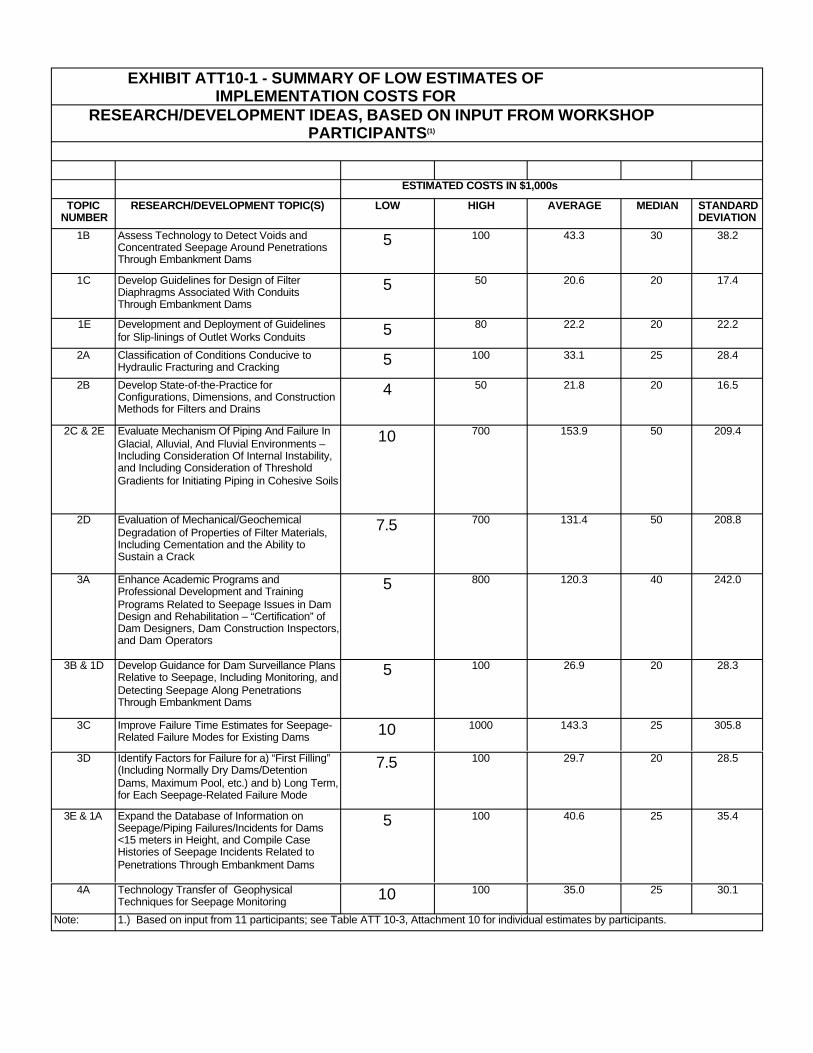
EXHIBIT ATT10-1 - SUMMARY OF LOW ESTIMATES OF IMPLEMENTATION COSTS FOR
RESEARCH/DEVELOPMENT IDEAS, BASED ON INPUT FROM WORKSHOP PARTICIPANTS(1)
ESTIMATED COSTS IN $1,000s
TOPIC NUMBER
RESEARCH/DEVELOPMENT TOPIC(S) LOW HIGH AVERAGE MEDIAN STANDARD DEVIATION
1B Assess Technology to Detect Voids and Concentrated Seepage Around Penetrations Through Embankment Dams
5 100 43.3 30 38.2
1C Develop Guidelines for Design of Filter Diaphragms Associated With Conduits Through Embankment Dams
5 50 20.6 20 17.4
1E Development and Deployment of Guidelines for Slip-linings of Outlet Works Conduits 5 80 22.2 20 22.2
2A Classification of Conditions Conducive to Hydraulic Fracturing and Cracking 5 100 33.1 25 28.4
2B Develop State-of-the-Practice for Configurations, Dimensions, and Construction Methods for Filters and Drains
4 50 21.8 20 16.5
2C & 2E Evaluate Mechanism Of Piping And Failure In Glacial, Alluvial, And Fluvial Environments – 10 700 153.9 50 209.4
Including Consideration Of Internal Instability, and Including Consideration of Threshold Gradients for Initiating Piping in Cohesive Soils
2D Evaluation of Mechanical/Geochemical Degradation of Properties of Filter Materials, Including Cementation and the Ability to Sustain a Crack
7.5 700 131.4 50 208.8
3A Enhance Academic Programs and Professional Development and Training 5 800 120.3 40 242.0
Programs Related to Seepage Issues in Dam Design and Rehabilitation – “Certification” of Dam Designers, Dam Construction Inspectors, and Dam Operators
3B & 1D Develop Guidance for Dam Surveillance Plans Relative to Seepage, Including Monitoring, and Detecting Seepage Along Penetrations Through Embankment Dams
5 100 26.9 20 28.3
3C Improve Failure Time Estimates for Seepage-Related Failure Modes for Existing Dams 10 1000 143.3 25 305.8
3D Identify Factors for Failure for a) “First Filling” (Including Normally Dry Dams/Detention Dams, Maximum Pool, etc.) and b) Long Term, for Each Seepage-Related Failure Mode
7.5 100 29.7 20 28.5
3E & 1A Expand the Database of Information on Seepage/Piping Failures/Incidents for Dams <15 meters in Height, and Compile Case Histories of Seepage Incidents Related to
5 100 40.6 25 35.4
Penetrations Through Embankment Dams
4A Technology Transfer of Geophysical Techniques for Seepage Monitoring 10 100 35.0 25 30.1
Note: 1.) Based on input from 11 participants; see Table ATT 10-3, Attachment 10 for individual estimates by participants.
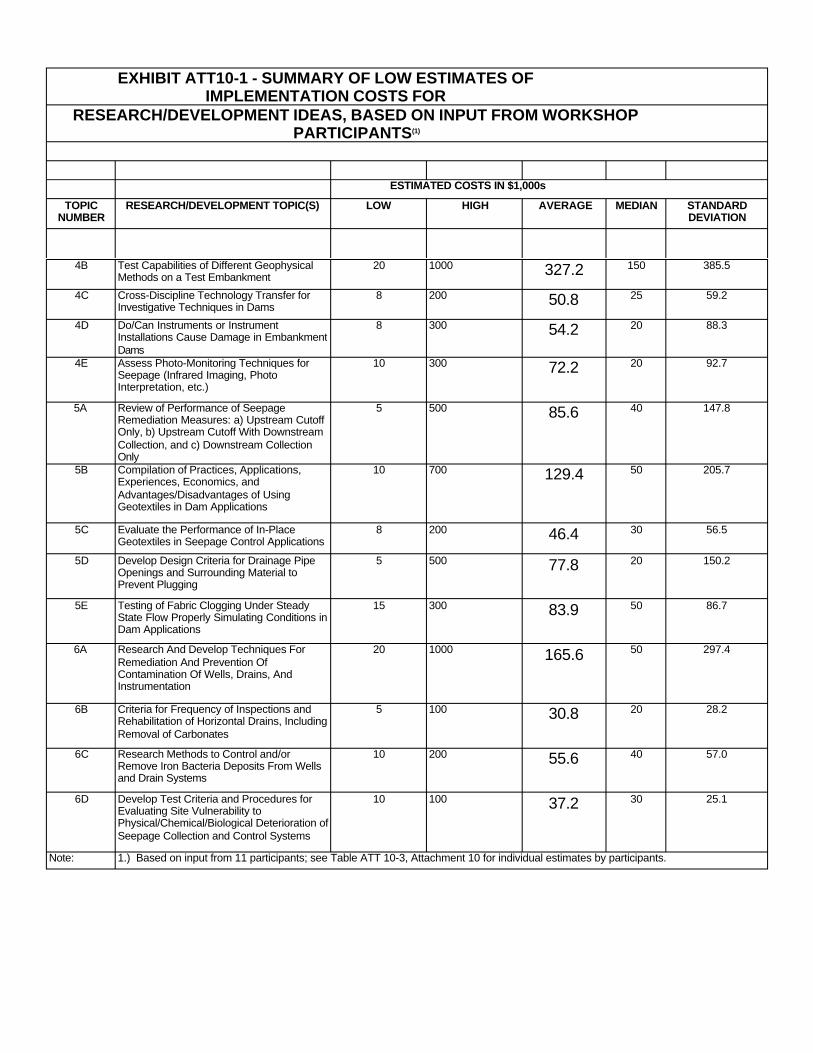
EXHIBIT ATT10-1 - SUMMARY OF LOW ESTIMATES OF IMPLEMENTATION COSTS FOR
RESEARCH/DEVELOPMENT IDEAS, BASED ON INPUT FROM WORKSHOP PARTICIPANTS(1)
ESTIMATED COSTS IN $1,000s
TOPIC NUMBER
RESEARCH/DEVELOPMENT TOPIC(S) LOW HIGH AVERAGE MEDIAN STANDARD DEVIATION
4B Test Capabilities of Different Geophysical Methods on a Test Embankment
20 1000 327.2 150 385.5
4C Cross-Discipline Technology Transfer for Investigative Techniques in Dams
8 200 50.8 25 59.2
4D Do/Can Instruments or Instrument Installations Cause Damage in Embankment Dams
8 300 54.2 20 88.3
4E Assess Photo-Monitoring Techniques for Seepage (Infrared Imaging, Photo Interpretation, etc.)
10 300 72.2 20 92.7
5A Review of Performance of Seepage Remediation Measures: a) Upstream Cutoff Only, b) Upstream Cutoff With Downstream
5 500 85.6 40 147.8
Collection, and c) Downstream Collection Only
5B Compilation of Practices, Applications, Experiences, Economics, and Advantages/Disadvantages of Using Geotextiles in Dam Applications
10 700 129.4 50 205.7
5C Evaluate the Performance of In-Place Geotextiles in Seepage Control Applications
8 200 46.4 30 56.5
5D Develop Design Criteria for Drainage Pipe Openings and Surrounding Material to Prevent Plugging
5 500 77.8 20 150.2
5E Testing of Fabric Clogging Under Steady State Flow Properly Simulating Conditions in Dam Applications
15 300 83.9 50 86.7
6A Research And Develop Techniques For Remediation And Prevention Of Contamination Of Wells, Drains, And Instrumentation
20 1000 165.6 50 297.4
6B Criteria for Frequency of Inspections and Rehabilitation of Horizontal Drains, Including Removal of Carbonates
5 100 30.8 20 28.2
6C Research Methods to Control and/or Remove Iron Bacteria Deposits From Wells and Drain Systems
10 200 55.6 40 57.0
6D Develop Test Criteria and Procedures for Evaluating Site Vulnerability to Physical/Chemical/Biological Deterioration of Seepage Collection and Control Systems
10 100 37.2 30 25.1
Note: 1.) Based on input from 11 participants; see Table ATT 10-3, Attachment 10 for individual estimates by participants.

EXHIBIT ATT10-2 - SUMMARY OF HIGH ESTIMATES OF IMPLEMENTATION COSTS FOR
RESEARCH/DEVELOPMENT IDEAS, BASED ON INPUT FROM WORKSHOP PARTICIPANTS(1)
ESTIMATED COSTS IN $1,000s
TOPIC NUMBER
RESEARCH/DEVELOPMENT TOPIC(S) LOW HIGH AVERAGE MEDIAN STANDARD DEVIATION
1B Assess Technology to Detect Voids and 15 1000 312.2 200 376.6 Concentrated Seepage Around Penetrations Through Embankment Dams
1C Develop Guidelines for Design of Filter 8 150 63.7 50 43.5 Diaphragms Associated With Conduits Through Embankment Dams
1E Development and Deployment of Guidelines for Slip-linings of Outlet Works Conduits
8 150 62.0 50 43.1
2A Classification of Conditions Conducive to Hydraulic Fracturing and Cracking
10 600 164.4 125 175.9
2B Develop State-of-the-Practice for 10 120 62.2 70 38.6 Configurations, Dimensions, and Construction Methods for Filters and Drains
2C & 2E Evaluate Mechanism Of Piping And Failure In 20 2000 649.4 250 774.6 Glacial, Alluvial, And Fluvial Environments – Including Consideration Of Internal Instability, and Including Consideration of Threshold Gradients for Initiating Piping in Cohesive Soils
2D Evaluation of Mechanical/Geochemical 10 2000 501.1 200 683.1 Degradation of Properties of Filter Materials, Including Cementation and the Ability to Sustain a Crack
3A Enhance Academic Programs and Professional Development and Training
10 1200 277.2 200 350.8
Programs Related to Seepage Issues in Dam Design and Rehabilitation – “Certification” of Dam Designers, Dam Construction Inspectors, and Dam Operators
3B & 1D Develop Guidance for Dam Surveillance Plans Relative to Seepage, Including Monitoring, and
10 300 85.6 60 82.7
Detecting Seepage Along Penetrations Through Embankment Dams
3C Improve Failure Time Estimates for Seepage-Related Failure Modes for Existing Dams
15 3000 438.3 100 908.4
3D Identify Factors for Failure for a) “First Filling” (Including Normally Dry Dams/Detention
13 400 131.9 60 123.5
Dams, Maximum Pool, etc.) and b) Long Term, for Each Seepage-Related Failure Mode
3E & 1A Expand the Database of Information on Seepage/Piping Failures/Incidents for Dams <15 meters in Height, and Compile Case Histories of Seepage Incidents Related to
20 500 160.0 100 165.4
Penetrations Through Embankment Dams
4A Technology Transfer of Geophysical Techniques for Seepage Monitoring
13 500 112.5 75 140.9
Note: 1.) Based on input from 11 participants; see Table ATT 10-5, Attachment 10 for individual estimates by participants.
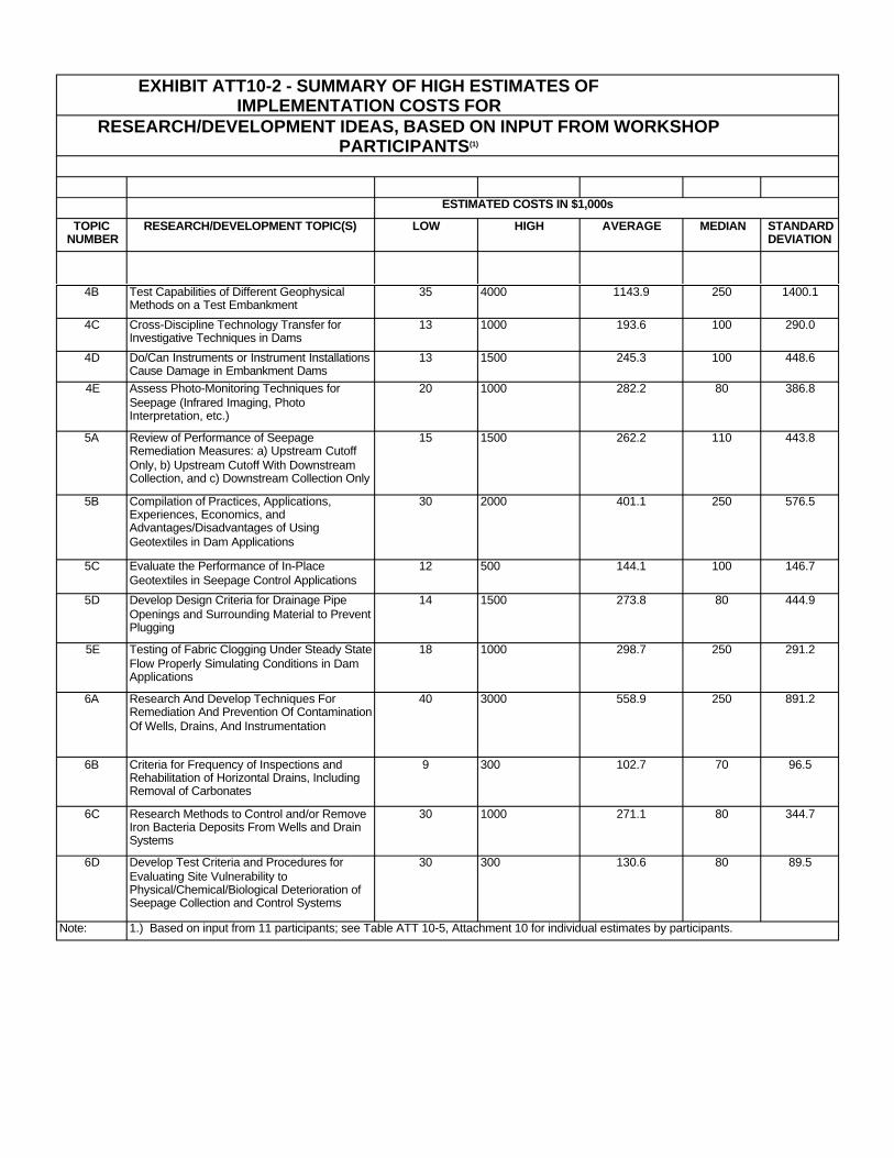
EXHIBIT ATT10-2 - SUMMARY OF HIGH ESTIMATES OF IMPLEMENTATION COSTS FOR
RESEARCH/DEVELOPMENT IDEAS, BASED ON INPUT FROM WORKSHOP PARTICIPANTS(1)
ESTIMATED COSTS IN $1,000s
TOPIC NUMBER
RESEARCH/DEVELOPMENT TOPIC(S) LOW HIGH AVERAGE MEDIAN STANDARD DEVIATION
4B Test Capabilities of Different Geophysical Methods on a Test Embankment
35 4000 1143.9 250 1400.1
4C Cross-Discipline Technology Transfer for Investigative Techniques in Dams
13 1000 193.6 100 290.0
4D Do/Can Instruments or Instrument Installations Cause Damage in Embankment Dams
13 1500 245.3 100 448.6
4E Assess Photo-Monitoring Techniques for 20 1000 282.2 80 386.8 Seepage (Infrared Imaging, Photo Interpretation, etc.)
5A Review of Performance of Seepage Remediation Measures: a) Upstream Cutoff
15 1500 262.2 110 443.8
Only, b) Upstream Cutoff With Downstream Collection, and c) Downstream Collection Only
5B Compilation of Practices, Applications, Experiences, Economics, and Advantages/Disadvantages of Using
30 2000 401.1 250 576.5
Geotextiles in Dam Applications
5C Evaluate the Performance of In-Place Geotextiles in Seepage Control Applications
12 500 144.1 100 146.7
5D Develop Design Criteria for Drainage Pipe 14 1500 273.8 80 444.9 Openings and Surrounding Material to Prevent Plugging
5E Testing of Fabric Clogging Under Steady State 18 1000 298.7 250 291.2 Flow Properly Simulating Conditions in Dam Applications
6A Research And Develop Techniques For 40 3000 558.9 250 891.2 Remediation And Prevention Of Contamination Of Wells, Drains, And Instrumentation
6B Criteria for Frequency of Inspections and 9 300 102.7 70 96.5 Rehabilitation of Horizontal Drains, Including Removal of Carbonates
6C Research Methods to Control and/or Remove 30 1000 271.1 80 344.7 Iron Bacteria Deposits From Wells and Drain Systems
6D Develop Test Criteria and Procedures for 30 300 130.6 80 89.5 Evaluating Site Vulnerability to Physical/Chemical/Biological Deterioration of Seepage Collection and Control Systems
Note: 1.) Based on input from 11 participants; see Table ATT 10-5, Attachment 10 for individual estimates by participants.
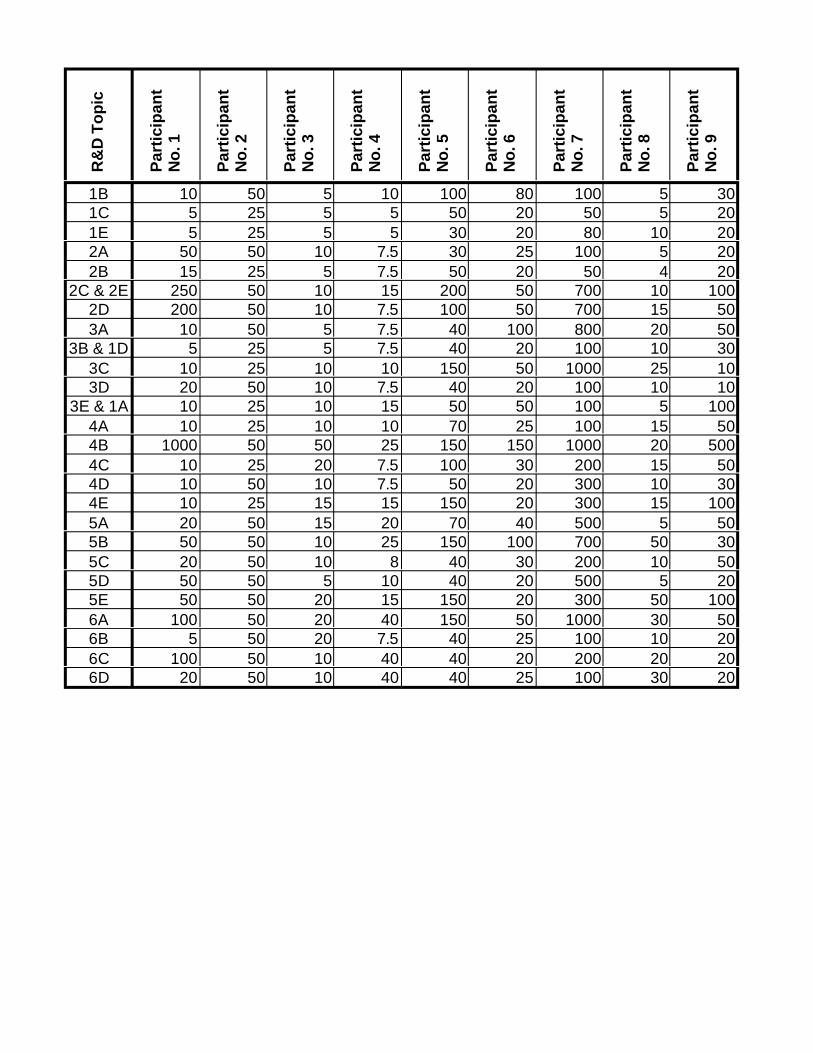
R&
D T
op
ic
Par
tici
pan
tN
o. 1
Par
tici
pan
tN
o. 2
Par
tici
pan
tN
o. 3
Par
tici
pan
tN
o. 4
Par
tici
pan
tN
o. 5
Par
tici
pan
tN
o. 6
Par
tici
pan
tN
o. 7
Par
tici
pan
tN
o. 8
Par
tici
pan
tN
o. 9
1B 10 50 5 10 100 80 100 5 30 1C 5 25 5 5 50 20 50 5 20 1E 5 25 5 5 30 20 80 10 20 2A 50 50 10 7.5 30 25 100 5 20 2B 15 25 5 7.5 50 20 50 4 20
2C & 2E 250 50 10 15 200 50 700 10 100 2D 200 50 10 7.5 100 50 700 15 50 3A 10 50 5 7.5 40 100 800 20 50
3B & 1D 5 25 5 7.5 40 20 100 10 30 3C 10 25 10 10 150 50 1000 25 10 3D 20 50 10 7.5 40 20 100 10 10
3E & 1A 10 25 10 15 50 50 100 5 100 4A 10 25 10 10 70 25 100 15 50 4B 1000 50 50 25 150 150 1000 20 500 4C 10 25 20 7.5 100 30 200 15 50 4D 10 50 10 7.5 50 20 300 10 30 4E 10 25 15 15 150 20 300 15 100 5A 20 50 15 20 70 40 500 5 50 5B 50 50 10 25 150 100 700 50 30 5C 20 50 10 8 40 30 200 10 50 5D 50 50 5 10 40 20 500 5 20 5E 50 50 20 15 150 20 300 50 100 6A 100 50 20 40 150 50 1000 30 50 6B 5 50 20 7.5 40 25 100 10 20 6C 100 50 10 40 40 20 200 20 20 6D 20 50 10 40 40 25 100 30 20
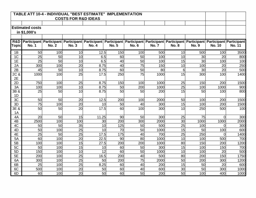
TABLE ATT 10-4 - INDIVIDUAL "BEST ESTIMATE" IMPLEMENTATION COSTS FOR R&D IDEAS
Estimated costs in $1,000's
R&D Participant Participant Participant Participant Participant Participant Participant Participant Participant Participant Participant Topic No. 1 No. 2 No. 3 No. 4 No. 5 No. 6 No. 7 No. 8 No. 9 No. 10 No. 11
1B 50 100 10 12.5 150 100 500 10 500 100 3500 1C 25 50 10 6.5 60 50 100 10 30 20 800 1E 25 50 10 6.5 40 50 100 15 30 100 100 2A 300 100 20 8.75 40 75 150 10 100 20 250 2B 45 50 10 8.75 60 50 80 6 30 20 500
2C & 2E
1000 100 25 17.5 250 75 1000 15 300 100 1400
2D 750 100 25 8.75 150 100 1000 25 150 200 1500 3A 100 100 10 8.75 50 200 1000 25 100 1000 900
3B & 1D
25 50 10 8.75 50 50 200 15 50 100 800
3C 50 50 20 12.5 200 100 2000 50 100 200 1500 3D 75 100 20 10 50 40 300 15 100 200 1500
3E & 1A
50 50 20 17.5 60 100 300 10 250 500 100
4A 20 50 15 11.25 90 50 300 25 75 0 300 4B 2500 100 100 30 200 300 2000 30 1000 1000 2000 4C 50 50 35 10 125 50 500 25 100 0 300 4D 50 100 25 10 70 50 1000 15 50 100 600 4E 25 50 25 17.5 175 40 700 25 250 0 1400 5A 60 100 20 22.5 90 80 1000 10 100 500 700 5B 100 100 15 27.5 200 200 1000 80 150 200 1200 5C 50 100 15 10 60 50 300 15 100 150 700 5D 150 100 10 12 60 50 1000 10 100 20 500 5E 200 100 25 16.5 200 40 500 80 200 150 1750 6A 300 100 25 50 200 75 2000 50 200 300 1200 6B 25 100 25 8.25 60 40 200 15 50 20 600 6C 500 100 20 50 60 40 600 30 50 300 1000 6D 60 100 20 50 60 50 200 50 100 400 1000
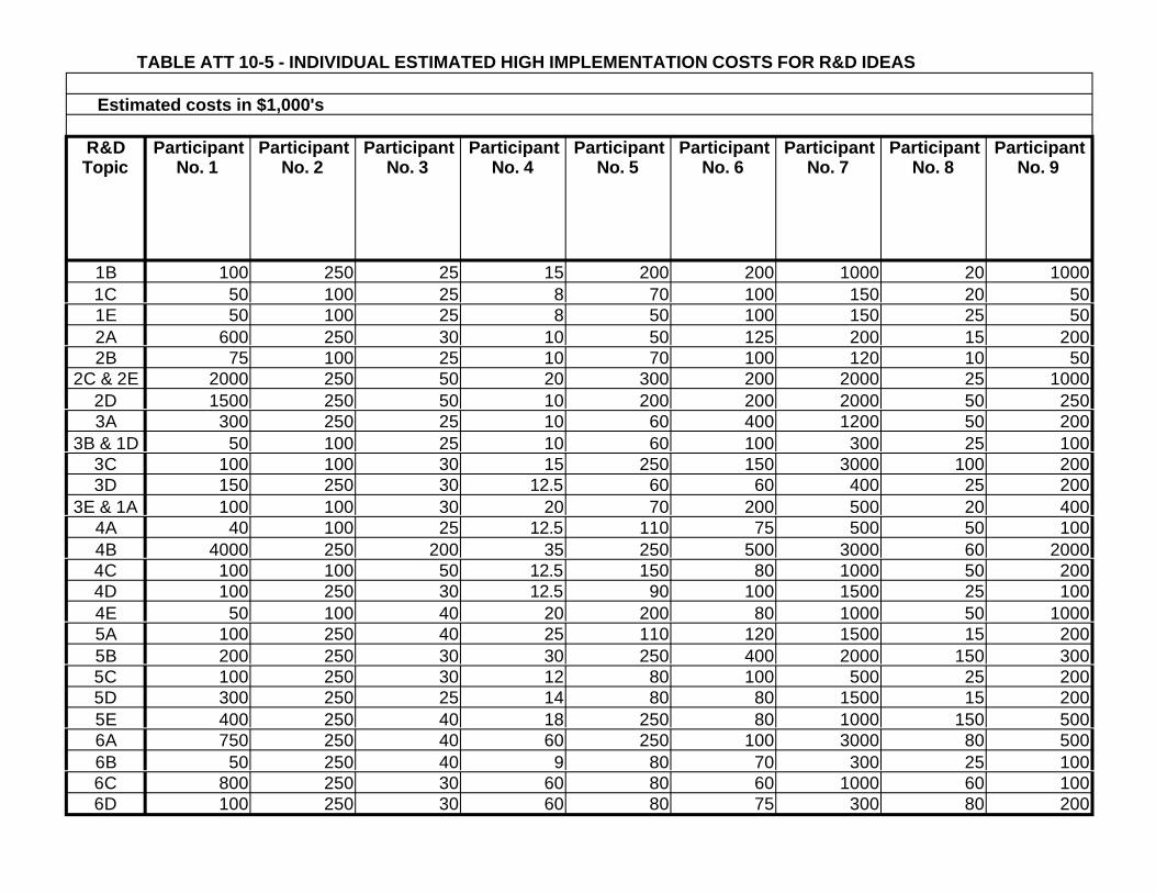
TABLE ATT 10-5 - INDIVIDUAL ESTIMATED HIGH IMPLEMENTATION COSTS FOR R&D IDEAS
Estimated costs in $1,000's
R&D Topic
Participant No. 1
Participant No. 2
Participant No. 3
Participant No. 4
Participant No. 5
Participant No. 6
Participant No. 7
Participant No. 8
Participant No. 9
1B 100 250 25 15 200 200 1000 20 1000 1C 50 100 25 8 70 100 150 20 50 1E 50 100 25 8 50 100 150 25 50 2A 600 250 30 10 50 125 200 15 200 2B 75 100 25 10 70 100 120 10 50
2C & 2E 2000 250 50 20 300 200 2000 25 1000 2D 1500 250 50 10 200 200 2000 50 250 3A 300 250 25 10 60 400 1200 50 200
3B & 1D 50 100 25 10 60 100 300 25 100 3C 100 100 30 15 250 150 3000 100 200 3D 150 250 30 12.5 60 60 400 25 200
3E & 1A 100 100 30 20 70 200 500 20 400 4A 40 100 25 12.5 110 75 500 50 100 4B 4000 250 200 35 250 500 3000 60 2000 4C 100 100 50 12.5 150 80 1000 50 200 4D 100 250 30 12.5 90 100 1500 25 100 4E 50 100 40 20 200 80 1000 50 1000 5A 100 250 40 25 110 120 1500 15 200 5B 200 250 30 30 250 400 2000 150 300 5C 100 250 30 12 80 100 500 25 200 5D 300 250 25 14 80 80 1500 15 200 5E 400 250 40 18 250 80 1000 150 500 6A 750 250 40 60 250 100 3000 80 500 6B 50 250 40 9 80 70 300 25 100 6C 800 250 30 60 80 60 1000 60 100 6D 100 250 30 60 80 75 300 80 200

REFERENCES
Åberg, B. (1993) Washout of grains from filtered sand and gravel materials. Journal of Geotechnical Engineering, ASCE, 119 (1), pp. 36-53.
ANCOLD (1972) Dams in Australia Australian National Committee on Large Dams.
ANCOLD (1990) Dams in Australia Australian National Committee on Large Dams.
ANCOLD (1992) Status of dam safety in Australia. ANCOLD Bulletin, Issue No. 91, August 1992, pp. 9-29.
Ang, H-S. and Tang, W.H. (1975) Probability Concepts in Engineering Planning and Design, Vol. 1, John Wiley.
Ang, H-S. and Tang, W.H. (1990) Probability Concepts in Engineering Planning and Design, Vol. 2, the authors.
Arulanandan, K. and Perry, E.B. (1983) Erosion in relation to filter design criteria in earth dams. Journal of Geotechnical Engineering ASCE, 109 (5), pp. 682-698.
Arulanandan, K., Gillogley, E. and Tully, R. (1980) Development of a Quantitative Method to Predict Critical Shear Stress and Rate of Erosion of Natural Undisturbed Cohesive Soils. U.S. Army Engineer Waterways Experiment Station, Vicksburg, MS, Technical Report No. GL-80-5.
Arulanandan, K., Loganathan, P. and Krone, R.B. (1975), Pore and eroding fluid influences on surface erosion of soils. Journal of the Geotechnical Engineering Division, ASCE. 101(GT1), pp. 55-66.
Arulanandan, K., Sargunam, A., Loganathan, P. and Krone, R.B. (1973), Application of chemical and electrical parameters to prediction of erodibility. In Soil Erosion: Causes and Mechanisms; Prevention and Control. Special Report 135, Highway Research Board, pp 42-51.
AS 1289 (1991) Methods of Testing Soils for Engineering Purposes, Australian Standard 1289, Standards Australia.
AS 1726 (1993) Geotechnical Site Investigations, Australian Standard 1726, Standards Australia.
Atkinson, J.H., Charles, J.A. and Mhach, H.K. (1990), Examination of erosion resistance of clays in embankment dams. Quarterly Journal of Engineering Geology, London, Vol. 23, 1990, pp. 103-108.
Baab, A.O., and Mermel, T.W. (1968). Catalog of Dam Disasters, Failures and Accidents. US Dept. of Interior, Bureau of Reclamation, Washington D.C.
BC Hydro (1995) Coursier Lake Dam D1, Supplement to the Defciency Investigation. 1st Estimate of the Probability of Failure by Piping. Report No. MEP11-1, BC Hydro, (Unpublished)
Bellport, B.P. (1967) Bureau of Reclamation experience in stabilizing embankment of Fontenelle Dam. Ninth International Congress on Large Dams, Istamboul, Q.32 R.5, pp. 67-79.
Benjamin, J.R. and Cornell, C.A. (1970) Probability, Statistics, and Decision for Civil Engineers, McGraw Hill.
Bickel, J.O. and Kuesel, T.R. (1992) Tunnel Engineering Handbook. Krieger Publishing Company, Florida.
Binnie, G.M. (1978) The collapse of the Dale Dyke dam in retrospect. Quarterly Journal Engineering Geology, 11, pp. 305-324.
Binnie, G.M. (1981) Early Victorian Water Engineers. Thomas Telford, London.
Biswas, A.K. and Chatterjee, S. (1971) Dam disasters: an assessment. Engineering Journal (March 1971), pp. 3-8.
Blind, H. (1983) The safety of dams. Water Power & Dam Construction (May.), pp. 17-21.
Bowles, D.S. (1993) Risk assessment: a tool for dam rehabilitation decisions. Proceedings of the Specialty Conference on Geotechnical Practice in Dam Rehabilitation, Geotechnical Special Publication No.35, ASCE, pp. 116-130.
Building Research Establishment (1990). An Engineering Guide to the Safety of Embankment Dams in the United Kingdom. Report CI/SfB 187. Building Research Establishment.
Burenkova, V.V. (1993) Assessment of suffusion in non-cohesive and graded soils. Filters in Geotechnical and Hydraulic Engineering, Brauns, Heibaum & Schuler (eds.), Balkema, Rotterdam, pp. 357-360.
Canadian Standards Association (1993) Guidelines and Requirements for Reliability Analysis Methods. Q636-93 Canadian Standards Association.
Cedeño, A.R., Jr. (1998). Piping in Dams : Tests to Assess the Factors which Affect Progression. CIVL4906 – Project/Thesis, School of Civil and Environmental Engineering, University of New South Wales.
Cedergren, H.R. (1973) Seepage control in earth dams. In Embankment Dam Engineering, Hirschfeld and Poulos eds., John Wiley, pp 21-45.
Cedergren, H.R. (1989) Seepage, Drainage, and Flow Nets. Third Edition, John Wiley.
CFGB (1997). Internal Erosion: Typology, Detection, Repair. Barrages and Reservoirs No.6. Comité Francais des Grands Barrages, Le Bourget-du-lac Cedex.
Chadwick, A. and Morfett, J. (1993) Hydraulics in Civil and Environmental Engineering. 2nd
Edition. E&FN Spon, London..
Chapius, R.P. (1986b). Quantitative measurement of the scour resistance of natural solid clays. Canadian Geotechnical Journal. 23. pp 132-141.
Chapius, R.P. and Gatien, T. (1986) An improved rotating cylinder technique for quantitative measurements of scour resistance of clays. Canadian Geotechnical Journal. 23(1) pp 8387.
Chapius, R.P. and Gatien, T. (1986). An improved rotating cylinder technique for quantitative measurements of the scour resistance of clays. Canadian Geotechnical Journal. 23. pp 83-87.
Chapuis, R.P. (1986a). Transportation Research Record 1089
Charles, J.A. (1997). General Report, Special Problems Associated with Earthfill Dams. Nineteenth International Congress on Large Dams, Florence, GR Q73, Vol.II, pp.1083-1198.
Charles, J.A. and Boden, J.B. (1985) The failure of embankment dams in the United Kingdom. Proceedings of the Symposium on Failures in Earthworks, London, Thomas Telford. pp. 181-202.
Charles, J.A., Tedd, P. and Holton, I.R. (1995) Internal erosion in clay cores of British dams. Research and Development in the Field of Dams, Crans-Montana, Switzerland, Swiss National Committee on Large Dams. pp. 59-70.
Christensen, R.W. and Das, B.M. (1973) Hydraulic erosion of remolded cohesive soils. In Soil Erosion: Causes and Mechanisms; Prevention and Control. Special Report 135, Highway Research Board, pp 8-19.
Cooke, J.B. (1984) Progress in rockfill dams. Journal of the Geotechnical Engineering Division, ASCE, 110 (10), pp. 1383-1414.
Dascal, O. (1984) Peculiar behaviour of the Manicouagan 3 Dam’s core. Proceedings of the International Conference on Case Histories in Geotechnical Engineering, University of Missouri- Rolla, Vol 2, pp. 561-567.
De Mello, V.F.B. (1975) Some lessons from unsuspected, real, and fictitious problems from 6thdam engineering in Brazil. Proceedings Regional African Conference on Soil
Mechanics and Foundation Engineering, Durban, Vol 2, pp. 285-304.
Douglas, K.J., Spannagle, M. and Fell, R. (1998) Analysis of Concrete and Masonry Dam Incidents. UNICIV Report No. R-373, School of Civil and Environmental Engineering, The University of New South Wales. ISBN: 85841 340 X.
Einsele, G. (1992) Sedimentary Basins: Evolution, Facies and Sediment Budget. Springer-Verlag. Germany.
Einstein, H.H. (1997) Landslide risk - Systematic approaches to assessment and management. Landslide Risk Assessment, (Ed. Cruden and Fell) Honolulu, Hawaii. A.A.Balkema. pp. 25-50.
Engineering News (1909) The partial failure through undermining of the Zuni dam, New Mexico. Engineering News, 62 (23), pp. 597-601.
Fairbridge, R.W. (1968) The Encyclopedia of Geomorphology. Reinhold Book Corporation. New York.
Fell, R and Foster, M (1997). Workshop on Risk Assessment for Piping and Internal Erosion of Dams, 2-5 December 1997, Sydney, Australia.
Fell, R and Foster, M. (1999) Risk assessment for embankment dams assessment of the probability of failure by piping. 8th ANZ Conference on Geomechanics Conference, Hobart, Vol.2, pp. 495-502.
Fell, R. (1995) Estimating the probability of failure of embankment dams under normal operating conditions and earthquake loading. In Dams, the Implications of Ownership, Proceedings of NZSOLD-ANCOLD Symposium, Christchurch. IPENZ, Proceedings of Technical Groups, Vol 21, Issue 1 (LD), ISSN 0111-9532, pp. 68-82.
Fell, R. (1996) Estimating the probability of failure of embankment dams under normal operating conditions. Repair and Upgrading of Dams, Proceedings, S. Johansson and M. Cederström, eds., SwedCOLD, pp. 567-576.
Fell, R. (1999) Personal communication.
Fell, R. and Foster, M. (1997) Estimation of the Probability of Piping Failure of Embankment Dams. Notes submitted to the USBR Seepage/Piping Risk Assessment Workshop, Bureau of Reclamation, Denver (Unpublished).
Fell, R., MacGregor, J.P., and Stapledon, D.H. (1992). Geotechnical Engineering of Embankment Dams. Balkema, 1992.
FEMA, US Army Corps of Engineers (1995) Water Control Infrastructure - National Inventory of Dams Update 1993-1994 [CD-ROM] Federal Emergency Management Agency.
Fitzpatrick, M.D. (1977) Reinforced rockfill in Hydro-Electric Commission Dams. ANCOLD Bulletin 49, pp. 20-26.
Foster, M. and Fell, R. (1999a) Filter testing for dams – no and continuing erosion boundaries. 8th ANZ Conference on Geomechanics, Hobart. Vol. 2, pp. 501-511.
Foster, M. and Fell, R. (1999b) A framework for estimating the probability of failure of embankment dams using event tree methods. School of Civil and Environmental Engineering, UNICIV Report No.R377, School of Civil and Environmental Engineering, UNSW. ISBN: 85841 3442.
Foster, M. Spannagle, M. and Fell, R. (1998) Analysis of embankment dam incidents. School of Civil and Environmental Engineering, UNICIV Report No.R374, School of Civil and Environmental Engineering, UNSW. ISBN: 85841 3493
Foster, M., and Fell, R. (1999) A Method for Assessing Embankment Dam Filters which do not Satisfy Modern Design Criteria. UNICIV Report No. R-376, School of Civil and Environmental Engineering, The University of New South Wales. ISBN: 85841 343 4.
Foster, M., Fell, R. and Spannagle, M. (1998) Analysis of Embankment Dam Incidents. UNICIV Report No. R-374, School of Civil and Environmental Engineering, The University of New South Wales. ISBN: 85841 349 3.
Fugisawa, T., Nakamura, A., Yamaguchi, Y. and Kawasaki, M. (1997) Effectiveness of granular filters for embankment dams against soil suspension. Nineteenth International Congress on Large Dams, Florence, ICOLD, Q.73 R.19, pp. 283-305.
Garga, V.K., Hansen, D. and Townsend, D.R. (1995) Mechanisms of massive failure for flowthrough rockfill embankments. Canadian Geotechnical Journal, 32, pp. 927-938.
Ghebreiyessus, Y.T., Gantzer, C.J., Alberts, E.E. and Lentz, R.W. (1994). Soil erosion by concentrated flow: shear stress and bulk density. Transactions of the ASAE. 37(6) pp. 1791-1797.
Gibbs, H.J. (1962). A Study of Erosion and Tractive Force Characteristics in Relation to Soil Mechanics Properties. United States Department of the Interior, Bureau of Reclamation, Division of Engineering Laboratories, Soils Engineering Report No. EM-643, February 23, 1962.
Gillen, C. (1982) Metamorphic Geology: An Introduction to Tectonic and Metamorphic Processes. George Allen & Unwin, London.
Gillon, M.D. and Newton, C.J. (1988) Matahina Dam: the initial lake filling incident and the long term performance of the repair. 5th Australia-New Zealand Conference on Geomechanics, Sydney, pp. 585-590.
Gomez Laa, G., Alonso Franco, M. and Hernandez, J.L.R. (1979) Reflections on some incidents in Spanish dams. Thirteenth International Congress on Large Dams, New Dehli, ICOLD. Vol. Q49 pp. 721-740.
Gordon, J.L. and Duguid, D.R. (1970) Experiences with cracking at Duncan Dam. Tenth International Congress on Large Dams, ICOLD, Q.36 R.29, Vol 1, pp. 469.
Graybeal, K.D. (1988) Seepage control at Mud Mountain Dam. Sixteenth International Congress on Large Dams, San Francisco, ICOLD. Q61. R.29, pp. 539-555.
Greutter, F. and Schnitter, N.J. (1982) Analytical risk assessment for dams. Fourteenth International Congress on Large Dams, ICOLD, Vol. 1 Q52 R39, pp. 611-625.
Gruner, E. (1963) Dam Disasters. Proceedings of the Institute of Civil Engineering (London), 24 pp. 47-60.
Gruner, E. (1967) The safety of reservoirs. World Dams Today, The Japan Dam Association pp. 104-109.
Hackney, G. (1994). Embankment Dams, and Their Probability of Failure. BE (Civil) Thesis, School of Civil Engineering, The University of New South Wales.
Hanson, G.J. (1991). Development of a Jet Index to Characterize Erosion Resistance of Soils in Earthen Spillways. Transactions of the ASAE. 34(5) pp. 2015-2020.
Hanson, G.J. (1992). Erosion resistance of compacted soils. Transportation Research Record 1369, pp. 26-30.
Hanson, G.J. and Robinson, K.M. (1993) The influence of soil moisture and compaction on spillway erosion. Transactions of the ASAE. 36(5) pp. 1349-1352.
Hartford, D.N.D. (1998) This dam risk business - the challenge of implementation - managing the risks of risk assessment. ANCOLD/NZSOLD Conference on Dams, Sydney.
Hatem, G.A. (1985) Development of a Data Base on Dam Failures in the United States: Preliminary Results, BE Thesis, Stanford University.
Henley, E.J. and Kumamoto, H. (1992) Probabilistic Risk Assessment. IEEE Press.
Hjeldnes, E.I. and Lavania, V.K. (1980) Cracking, leakage and erosion of earth dam materials. Journal of the Geotechnical Engineering Division, ASCE. 106 (GT2) pp. 117-135.
Høeg, K., Johansen, P.M., Kjærnsli, B. and Torblaa, I. (1998) Internal Erosion in Embankment Dams. Research Project Sponsored by Norwegian Electricity Federation (EnFO). (In Norwegian with English summary).
Holtz, R.D. and Kovacs, W.D. (1981) An Introduction to Geotechnical Engineering. Prentice Hall, Englewood Cliffs, New Jersey.
Honjo, Y. and Veneziano, D. (1989) Improved filter criterion for cohesionless soils. Journal of Geotechnical Engineering, ASCE, 115 (1), pp. 75-94.
Hosmer, D.W. and Lemeshow, S. (1989) Applied Logistic Regression. John Wiley & Sons, New York.
Hsu, S.J.C. (1981) Aspects of piping resistance to seepage in clayey soils. Tenth International Conference on Soil Mechanics and Foundation Engineering, Stockholm, A.A. Balkema. Vol. 1 pp. 421-428.
ICOLD (1969) Progress Report on ICOLD Committee on Failure and Accidents to Large Dams other than in Connection with the Foundations. Unpublished report presented to the Executive Meeting in Warsaw, Poland, September 1969.
ICOLD (1973) World Register of Dams ICOLD.
ICOLD (1974) Lessons from Dam Incidents. Complete Ed. ICOLD.
ICOLD (1976) World Register of Dams 1st Updating. ICOLD.
ICOLD (1978). Technical Dictionary on Dams. ICOLD.
ICOLD (1979) World Register of Dams 2nd Updating. ICOLD.
ICOLD (1983) Deterioration of Dams and Reservoirs ICOLD.
ICOLD (1984) World Register of Dams 3rd Updating. ICOLD.
ICOLD (1989) Bulletin 70 - Rockfill Dams with Concrete Facing. State of the Art. ICOLD.
ICOLD (1990) Bulletin 77 - Dispersive Soils in Embankment Dams. Review. ICOLD.
ICOLD (1994) Bulletin 95 -Embankment Dams Granular Filters and Drains. Review and Recommendations. ICOLD.
ICOLD (1994) Bulletin 95 Embankment dams granular filters and drains. ICOLD.
ICOLD (1995) Bulletin 99 - Dam Failures Statistical Analysis. ICOLD.
Independent Panel to Review Cause of Teton Dam Failure (1976) Failure of Teton Dam. Report to U.S. Department of the Interior and State of Idaho, U.S. Government Printing Office.
Ingles, O. G. (1984) A short study of dam failures in Australia, 1857-1983. Civil Engineering Systems, Vol 1 (June). 190-194.
Ingles, O.G. (1988) A review of dam failure: past, present and future. Flood insurance and relief in Australia (D. I. &. H. Smith J.W. ed.), Australian National University, Canberra, pp. 159-167.
Ingles, O.G. and Metcalf, J.B. (1972) Soil Stabilization. Butterworths.
James, J.P. and Wickham, R.T. (1970). Failure and Rectification of the Morwell No.2 Fire Service Reservoir. ANCOLD Bulletin, July 1970, pp.20-34.
Jaworski, G.W., Duncan, J.M. and Seed, H.B. (1981) Laboratory study of hydraulic fracturing. Journal of the Geotechnical Engineering Division, ASCE, 107 (GT6) pp. 713732.
Johansen, P.M., Vick, S.G. and Rikartsen, C. (1997) Risk analysis for three Norwegian dams. Hydropower ’97, Broch, Lysne, Flatabø and Helland-Hansen (eds.), Balkema, pp. 431442.
Jones, O.T. (1988) Canal failure on Wheao Power Scheme. Fifth Australia-New Zealand Conference on Geomechanics, Sydney, pp. 561-566.
Junchun, L.I. (1984) Practical examples of safety monitoring and analysis for earth and rockfill dams. International Conference on Safety of Dams, (J. L. Serafim ed.) Coimbra, A.A. Balkema. pp. 417-423.
Justo, J.L. (1988) The failure of the impervious facing of Martin Gonzalo rockfill dam. Sixteenth International Congress on Large Dams, San Francisco, ICOLD. Discussions and Contributions Q.61-19, pp. 252-266.
Kamphuis, J.W. and Hall, K.R. (1983) Cohesive material erosion by unidirectional current. ASCE Journal of Hydraulic Engineering, 109 (HY1), pp. 49-61.
Kandiah, A. and Aulanandan, K. (1974). Transportation Research Record No. 497.
Karpoff, K.P. (1955) The use of laboratory tests to develop design criteria for protective filters, Proceedings, American Society of Testing Materials, Volume. 55, pp. 1183-1198.
Keller, H. (1994) Investigation concerning the failure of Zoeknog Dam: findings. Eighteenth International Congress on Large Dams, Durban, ICOLD. Q.68 Discussions, pp. 205-210.
Kenney, T.C. (1983) Discussion of: Design of filters for clay cores of dams. Journal of the Geotechnical Engineering Division, Vol. 109, No.9, pp. 1191-1193.
Kenney, T.C. and Lau, D. (1984) Stability of particle grading of compacted granular filters. Technical Report 84-06, Department of Civil Engineering, University of Toronto.
Kenney, T.C. and Lau, D. (1985) Internal stability of granular filters. Canadian Geotechnical Journal, Vol. 22, pp. 215-225.
Kenney, T.C. and Lau, D. (1986) Closure to: Internal stability of granular filters. Canadian Geotechnical Journal, Vol. 23, pp. 420-423.
Kenney, T.C. and Westland. (1993) Laboratory study of segregation of granular filter materials. Filters in Geotechnical and Hydraulic Engineering, Brauns, Heibaum and Schuler (Eds). Balkema, Rotterdam, pp.313-319.
Kenney, T.C., Chahal, R., Chiu, E., Ofoegbu, G.I., Omange, G.N. and Ume, C.A. (1985) Controlling constriction sizes of granular filters. Canadian Geotechnical Journal, 22 (1), pp. 32-43.
Kenney, T.C., Lau, D. and Clute, G. (1984) Filter tests on 235mm diameter specimens of granular materials. Technical Report 84-07, Department of Civil Engineering, University of Toronto.
Khor, C.H. and Woo, H.K. (1989) Investigation of crushed rock filters for dam embankment. Journal of Geotechnical Engineering, ASCE, 115 (3), pp. 399-412.
Kjærnsli, B., Valstad, T. and Høeg, K. (1992) Rockfill Dams: Design and Construction. Hydropower Development Vol. 10, Norwegian Institute of Technology, Division of Hydraulic Engineering.
Knight, D.J. (1990). The proven usefulness of instrumentation systems on varied dam projects. In Geotechnical instrumentation in practice, Thomas Telford, London, pp. 401414.
Kulhawy, F.H. and Gurtowski, T.M. (1976) Load transfer and hydraulic fracturing in zoned dams. Journal of the Geotechnical Engineering Division, ASCE. 102(GT9), pp. 963-974.
Kuusiniemi, R. (1991) Internal erosion of the Uljua earth dam. Seventeenth Congress on Large Dams, Vienna, ICOLD, Q.65- Discussion pp. 257-262.
Kuusiniemi, R., Polla, J. and Rathmayer, H. (1992) Internal erosion at the Uljua earth dam. Water Power & Dam Construction, March, pp. 27-30.
Lafleur, J., Mlynarek, J. and Rollin, A.L. (1989) Filtration of broadly graded cohesionless soils. Journal of Geotechnical Engineering ASCE, 115 (12), pp. 1747-1768.
Lambe, T.W. (1958) The engineering behaviour of compacted clay. Journal of the Soil Mechanics and Foundations Division, ASCE, 84 (SM2), pp. 1655-1 to 1655-35.
Landon-Jones, I., Wellington, N.B. and Bell, G. (1996) Risk assessment of Prospect Dam. ANCOLD Bulletin, No. 103, August, pp. 16-30.
Lawson, J.D. (1987) The protection of rockfill dams and coffer dams against overflow and throughflow – the Australian experience. Civil Engineering Transactions, Institution of Engineers Australia, Vol. CE29, No. 3.
Lawton, E.C., Fragaszy, R.J. and Hetherington, M.D. (1992) Review of wetting-induced collapse in compacted soil. Journal of Geotechnical Engineering, ASCE, 118 (9), pp. 1376-1394.
LeBihan, J.-P. and Leroueil, S. (1998) Transient Water Flow Through Unsaturated Soils Implications for Earth Dams. Report GCT-98-18, Faculté des Sciences et de Génie, Université Laval.
Leonards, G.A. and Narain, J. (1963) Flexibility of clay and cracking of earth dams. Journal of the Soil Mechanics and Foundations Division, ASCE March 1963 (SM2), pp. 47-98.
Leps, T.M. (1973) Flow through rockfill dams. In Embankment Dam Engineering, Hirschfeld and Poulos eds., John Wiley and Sons, pp. 87-107.
Leps, T.M., Strassburger, A.G. and Meehan, R.L. (1978) Seismic stability of hydraulic fill dams, Part I. Water Power and Dam Construction (October 1978), pp. 27-36.
Little, A.L. (1967) The use of tropically weathered soils in the construction of earth dams. Proceedings 3rd Asian Regional Conference on Soil Mechanics and Foundation Engineering, Haifa, Vol 1, p. 35.
Lo, K.Y. and Kaniaru, K. (1990) Hydraulic fracture in earth and rock-fill dams. Canadian Geotechnical Journal, 27, pp. 496-506.
Lofquist, B. (1992) Hydraulic penetration in embankment dams. Ground Engineering, 25(5), pp. 40-43.
Lowe, J. and Binger, W.V. (1982) Tarbela Dam Project, Pakistan. Second Annual USCOLD Lecture, United States Committee on Large Dams.
Lyle, W.M. and Smerdon, E.T. (1965). Relation of compaction and other soil properties to erosion resistance of soils. Transactions of the ASAE. 8(3) pp. 419-422.
Maranha das Neves, E. (1989). Analysis of Crack erosion in dam cores. The crack erosion test. de Mello Volume, Sao Paulo, Brazil, pp. 284-298.
Marsal, R.J. (1982) Monitoring of embankment dam behaviour. Fourteenth International Congress on Large Dams, Rio de Janeiro, ICOLD, Q.52 R.84, pp. 1441-1467.
Marsal, R.J. and Tamez, G. (1955) Earth dams in Mexico, design, construction and performance. Fifth International Congress on Large Dams, ICOLD, Communications C.30, pp. 1123-1178.
Masch, F.D., Jr., Espey, W.H., Jr., and Moore, W.L. (1963). Measurements of the Shear Resistance of Cohesive Sediments. Proceedings of the Federal Inter-Agency Sedimentation Conference, Agricultural Research Service, Publication No. 970, Washington, D.C., pp. 151-155.
McCormick, N.J. (1981) Reliability and Risk Analysis - Methods and Nuclear Power Applications, Academic Press, New York.
Melvill, A.L. (1997). The performance of a number of culverts in fill dams. Nineteenth International Congress on Large Dams, Florence. Q73, R36, pp.567-586.
Middlebrooks, T.A. (1953) Earth-dam practice in the United States. A.S.C.E. Transactions (Paper 2620), pp. 697-722.
Milligan, V. (1976) Geotechnical aspects of glacial tills. In Glacial Till An Inter-disciplinary Study. The Royal Society of Special Publications, No.12. (Ed. Legget). Royal Society of Canada, Ottawa.
Mitchell, W.R. and Fitzpatrick, M.D. (1979) An incident at Rowallan dam. Thirteenth International Congress on Large Dams, New Dehli, ICOLD. Q49, pp. 195-210.
Moore, W.L. and Masch, F.D., Jr. (1962). Experiments on the Scour Resistance of Cohesive Sediments. Journal of Geophysical Research, Vol. 67, No. 4, April 1962, pp. 1437-1449.
Mostyn, G.R. and Fell, R. (1997) Quantitative and semiquantitative estimation of the probability of landsliding. Landslide Risk Assessment, (Ed. Cruden and Fell) Honolulu, Hawaii. A.A.Balkema. pp. 297-316.
Murti, N.G.K. (1977) Panshet Dam failure - an interpretation. Journal of the Institution of Engineers (India), 58 (Part CI 1), pp. 26-33.
NGI (1984) Internal Report, Jukla Saddle Dam, Leakages, Rehabilitation, Documentation of Piping through the Core. (In Norwegian). Unpublished Report. Norwegian Geotechnical Institute.
NGI (1984) Jukla Sekundærdam Lkkaasjer, Reparasjoner, Påvisning av erosjonskanaler Gjennom Tetningskjernen. (Jukla Saddle Dam, Leakages, Rehabilitations, Documentations of Piping Through the Core) Internal Report 53600-1, Norges Geotekniske Institutt, Oslo. (In Norwegian)
Nielson, N.M., Vick, S.G. and Hartford, D.N.D. (1994) Risk analysis in British Colombia. International Water Power & Dam Construction, March, 1994.
Nilsson, Å. And Mikaelsson, J. (1996) Ground water pressure increase and internal erosion at Långbörn Dam. Repair and Upgrading of Dams, Proceedings, S. Johansson and M. Cederström, eds., SwedCOLD, pp. 207-217.
NZSOLD (1988) Dams in New Zealand. New Zealand Society on Large Dams.
Oborn, L.E. (1988) Canal failure, Ruahihi Hydro Power Scheme, Bay of Plenty, New Zealand. Fifth Australia-New Zealand Conference on Geomechanics, Sydney, pp. 574584.
Olivier, H. (1967) Through and overflow rockfill dams - new design techniques. Proceedings Institution of Civil Engineers, Vol. 36, March, pp. 433-464.
Olwage, H.J.W. and Oosthuizen, C. (1984) Lessons learnt from South African dam incidents. Safety of Dams, Coimbra, A.A.Balkema, Rotterdam. pp. 33-39.
Pécsi, M. (1980) Studies on Loess. International Union for Quaternary Research Commission on Loess. Budapest.
Paaswell, R.E. (1973) Causes and mechanisms of cohesive soil erosion: the state of the art. Highway Research Board, Special Report No. 135, pp. 52-74.
Parkin, A.K. (1971) Field solutions for turbulent seepage flow. Journal of the Soil Mechanics and Foundations Division, ASCE, 97(SM1), pp. 209-218.
Paté-Cornell, M.E. (1984) Fault tree vs. event trees in reliability analysis. Risk Analysis, Vol. 4 No.3, pp. 177-186.
Peck, R. (1990) Interface between core and downstream filter. Proceedings H Bolton Seed Memorial Symposium, BiTech Publishers, Vol. 2, pp. 237-251.
Peck, R.B. (1980) Where has all the judgement gone? Canadian Geotechnical Journal, 17 (4), pp. 584-590.
Perlea, V. (1984) Lessons from embankment dam accidents. An introduction. Int. Conf. On Case Histories in Geotechnical Engineering, St. Louis, University of Missouri-Rolla. Vol. 4, pp. 1571-1580.
Pettijohn, F.J. (1975) Sedimentary Rocks. Third Edition. Harper & Row Publishers. New York.
Proctor, R.R. (1933) The design and construction of rolled earth dams. Engineering News Record, Volume 111, pp. 245,286, 348, 372.
Public Works Department, NSW (1967) Foundation problems at Mardi Dam, NSW. ANCOLD Bulletin, Issue No. 23, pp. 21-24.
Ravaska, O. (1997) Piping susceptibility of glacial till, 19th International Congress on Large Dams, Q73 R30, ICOLD Florence. 455-471.
Reddi, L.N., Lee, I.M. and Bonala, M.V.S. (2000). Comparison of Internal and Surface Erosion Using Flow Pump Tests on a Sand-Kaolinite Mixture. Geotechnical Testing Journal, GTJODJ, Vol. 23, No.1, March 2000, pp. 116-122.
Regalado, G., Materton, B., Ortega, J.W. and Vargas, J. (1982) Alto Anchicaya concrete face rockfill dam behaviour of the concrete face membrane. Fourteenth International Congress on Large Dams, Rio de Janeiro, ICOLD. Q.55 R.30, pp. 517-535.
Ripley, C.F. (1983) Discussion of: Design of filters for clay cores of dams. Journal of Geotechnical Engineering ASCE, 109 (9), pp. 1193-1195.
Ripley, C.F. (1984) Discussion of: Progress in rockfill dams. Journal of Geotechnical Engineering ASCE, 114 (2), pp. 236-240.
Ripley, C.F. (1986) Discussion of: Internal stability of granular filters. Canadian Geotechnical Journal, 23, pp. 255-258.
Ripley, C.F. (1986) Internal stability of granular filters: Discussion. Canadian Geotechnical Journal, 23 pp. 255-258.
Rutledge, P.C. and Gould, J.P. (1973) Movements of articulated conduits under earth dams on compressible foundations. In Embankment Dam Engineering, Hirschfeld and Poulos eds., John Wiley and Sons, pp 209-237.
Sargunan, A (1976). Concept of Critical Shear Stress in Relation to Characterization of Dispersive Clays. In Dispersive Clays, Related Piping, and Erosion in Geotechnical Projects.
Schnitter, N.J. (1994) A History of Dams - The Useful Pyramids. A.A.Balkema, Rotterdam, pp. 266.
Schuler, U. (1995) How to deal with the problem of suffusion. Research and Development in the Field of Dams, Swiss National Committee on Large Dams, pp 145-159.
Scott, B.G. (1976) Failure and reconstruction of an old earth dam. Water Power and Dam Construction, February, pp. 33-36.
Senneset, K. (1996) Personal Communication - List of Norwegian embankment dams with height more than 15m.
Serafim, J.L. (1981a) Elements for a thorough statistical analysis of dam failures. Revista da Universidade de Coimbra.
Serafim, J.L. (1981b) Safety of dams judged from failures. Water Power & Dam Construction. (Dec.), pp. 32-35.
Shaikh, A., Ruff, J.F. and Abt, SR. (1988a) Erosion rate of compacted NA-montmorillonite soils. Journal of Geotechnical Engineering, ASCE. 114(3) pp. 296-305.
Shaikh, A., Ruff, J.F., Charlie, W.A. and Abt, S.R. (1988). Erosion rate of dispersive and nondispersive clays. Journal of Geotechnical Engineering. 114(5) pp. 589-600.
Sherard, J.L. (1953). Influence of Soil Properties and Construction Methods on the Performance of Homogeneous Earth Dams. Technical Memorandum 645, United States Bureau of Reclamation, Denver, Colorado.
Sherard, J.L. (1973) Embankment dam cracking. In Embankment Dam Engineering, Hirschfeld and Poulos eds. John Wiley & Sons, New York, pp.271-353.
Sherard, J.L. (1979) Sinkholes in dams of coarse, broadly graded soils. Thirteenth International Congress on Large Dams, New Dehli, ICOLD. Q.49 R.2, pp. 325-334.
Sherard, J.L. (1983) Discussion of: Design of filters for clay cores of dams. Journal of Geotechnical Engineering ASCE, 109 (9), pp. 1195-1197.
Sherard, J.L. (1985) The upstream zone in concrete face rockfill dams. Concrete Face Rockfill Dams - Design, Construction, and Performance, Cooke and Sherard (eds.), ASCE, pp. 618-641.
Sherard, J.L. (1985a) Hydraulic fracturing in embankment dams. Proceedings, Symposium on Seepage and Leakage from Dams and Impoundments, (Volpe and Kelly eds.), ASCE, pp. 115-141.
Sherard, J.L. (1985b) The upstream zone in concrete face rockfill dams. Concrete Face Rockfill Dams - Design, Construction, and Performance, Cooke and Sherard (eds.), ASCE, pp. 618-641.
Sherard, J.L. and Dunnigan, L.P. (1985) Filters and leakage control in embankment dams. Seepage and Leakage from Dams and Impoundments, (R.L.V. &. W.E. Kelly ed.) Denver, Colorado, ASCE. pp. 1-30.
Sherard, J.L. and Dunnigan, L.P. (1989) Critical filters for impervious soils. Journal of Geotechnical Engineering, ASCE, 115 (7), pp. 927-947.
Sherard, J.L., (1985) Memorandum 1A to 1H, Unpublished reports of filter research carried out in the Lincoln, Nebraska, Soil Conservation Service Soil Mechanics Laboratory.
Sherard, J.L., Decker, J.L. and Ryker, N.L. (1972a) Piping in earth dams of dispersive clay. Proceedings, Specialty Conference on Performance of Earth and Earth-Supported Structures, ASCE, Vol 1, Part 1, pp. 589-626.
Sherard, J.L., Decker, R.S. and Ryker, N.L. (1972b) Hydraulic fracturing in low dams of dispersive clay. Proceedings, Specialty Conference on Performance of Earth and Earth-Supported Structures, ASCE, Vol 1, Part 1, pp. 653-689.
Sherard, J.L., Dunnigan, L.P. and Talbot, J.R. (1984a) Basic properties of sand and gravel filters. Journal of Geotechnical Engineering, ASCE, 110 (6), pp. 684-700.
Sherard, J.L., Dunnigan, L.P. and Talbot, J.R. (1984b) Filters for silts and clays. Journal of Geotechnical Engineering, ASCE, 110 (6), pp. 701-718.
Sherard, J.L., Dunnigan, L.P., Decker, R.S. and Steel, E.F. (1976) Pinhole test for identifying dispersive soils. Journal of the Geotechnical Engineering Division, ASCE, 102 (GT1), pp. 69-85.
Sherard, J.L., Dunnigan, L.P., Decker, R.S. and Steele, E.F. (1976). Journal of Geotechnical Engineering Division, ASCE. 102, No. GT1, January 1976, pp. 69-85.
Sherard, J.L., Woodward, R.J., Gizienski, S.F., and Clevenger, W.A. (1963) Earth and Earth-Rock Dams, John Wiley & Sons.
Silveira, A. (1984) Statistical analysis of deteriorations and failures of dams. Safety of Dams, (J. L. Serafim ed.) Coimbra, A.A. Balkema. pp. 55-60.
Silveira, A. (1990) Some considerations on the durability of dams. Water Power & Dam Construction. (Feb.), pp. 19-28.
Skempton, A.W. (1990) Historical development of British embankment dams to 1960. Clay barriers for embankment dams, London, Thomas Telford. pp. 15-52.
Skempton, A.W. and Brogan, J.M. (1994) Experiments on piping in sandy gravels. Géotechnique, 44 (3), pp. 449-460.
Slopek, R.J., Courage, L.J.R. and Keys, R.A. (1990) Three Sisters Dam - investigations and monitoring. Canadian Dam Safety Conference, Toronto, BiTech Publishers, pp. 19-32.
Snethlage, J.B., Scneidenhelm, F.W., and Vanderlip, A.N. (1958) Rockfill dams: review and statistics, Journal of the Power Division, ASCE, 84 (PO4).
Solvik, Ø (1991) Throughflow and stability problems in rockfill dams exposed to exceptional loads, Sixteenth International Congress on Large Dams, Q.67 R.20, ICOLD, pp. 333-343.
SPSS (1995) SPSS for Windows Advanced Statistics Release 6.0. SPSS Inc, Chicago.
Stanev, G. (1994) Failure and repair of the low-level outlet through an earthfill dam. 17th International Congress on Large Dams, Q.71 R.33, ICOLD, pp. 501-507.
St-Arnaud, G. (1995) The high pore pressures within in embankment dams: an unsaturated soil approach. Canadian Geotechnical Journal, 32, pp. 892-898.
Swiger, W.F. (1988) Earthfill Dam Performance and Remedial Measures – Logan Martin Dam. In Advanced Dam Engineering for Design, Construction and Rehabilitation. (Jansen ed.), Van Nostrand Reinhold, New York, pp. 362-363.
Symposium, Seventy-ninth Annual Meeting, American Society for Testing and Materials, Chicago, III., 27 June – 2 July 1976, ASTM Special Technical Publication 623, Sherard, J.L. and Decker R.S. eds.
Takase, K. (1967) Statistic study on failure, damage and deterioration of earth dams in Japan. Ninth Congress on Large Dams, Istanbul, ICOLD. Q34 R1, pp. 1-19.
Tavares, L.V. and Serafim, J.L. (1983) Probabilistic study on failure of large dams. Journal of the Geotechnical Engineering Division, ASCE, 109 (11), pp. 1483-1486.
Tawil, A.H. (1985) Regulatory priorities in monitoring Canadian Dams. 15th ICOLD Congress, Lausanne. Q56 R2, pp. 29-40.
Terzaghi, K. and Peck, R.B. (1967) Soil Mechanics in Engineering Practice. Second Edition, John Wiley.
Townsend, F.C., Bloomquist, D., Shiau, J-M., Martinez, R. and Rubin, H. (1988) Evaluation of Filter Criteria and Thickness for Migrating Piping in Sands. Department of Civil Engineering, University of Florida, Report for U.S. Bureau of Reclamation.
Truscott, E.G. (1977) Behaviour of Embankment Dams. Ph.D. Thesis. Department of Civil Engineering, Imperial College of Science and Technology, London.
Twidale, C.R. (1982) Granite Landforms. Elsevier Scientific Publishing Company, Amsterdam.
U.S. Army Corps of Engineers (1953) Filter Experiments and Design Criteria. Technical Memorandum No. 3-360, Waterways Experiment Station, Vicksburg.
U.S. Army Corps of Engineers (1987) Laboratory Tests on Granular Filters for Embankment Dams. Technical Report GL-87-22, Waterways Experiment Station, Vicksburg.
USBR (1960) Laboratory Filter Tests on Concrete Sand and Gravel, EM-588, U.S. Bureau of Reclamation, Denver.
USBR (1962) A Study of Erosion and Tractive Force Characteristics in Relation to Soil Mechanics Properties Earth Research Program. Soils Engineering Report No. EM-643. United States Department of the Interior Bureau of Reclamation, Denver.
USBR (1977) Design of Small Dams. United States Department of the Interior, Bureau of Reclamation.
USBR (1987) Design of Small Dams. Third Edition. U.S. Department of the Interior, Bureau of Reclamation.
USBR (1987) Design Standards No.13 Embankment Dams, Chapter 8 Seepage Analysis and Control. U.S. Department of the Interior, Bureau of Reclamation.
USBR (1987). Guidelines for Controlling Seepage Along Conduits Through Embankments, ACER Technical Memo No.9, U.S. Department of the Interior, Bureau of Reclamation.
USBR (1988) Results of Geologic Investigations and Data Evaluation for Meeks Cabin Dam, Lyman Project, Wyoming. Report No. G-441, U.S. Department of the Interior, Bureau of Reclamation. (Internal Report).
USBR (1989) Geological Exploration for Lake Alice Dams No.1 and 1-½, North Platte Project - Nebraska. U.S. Department of the Interior, Bureau of Reclamation. (Internal Report).
USBR (1990) Analyses of Geological and Geotechnical Issues at Lake Alice Dams No.1 and 1-½ for Modification Decision Analysis. Tech. Memo. No. LA-3620-MDA-1, U.S. Department of the Interior, Bureau of Reclamation. (Internal Report).
USBR (1994) Maximum Sections and Earthwork Control Statistics of Earth-Fill Dams Built by the Bureau of Reclamation. United States Department of the Interior, Bureau of Reclamation.
USCOLD (1975) Lessons from Dam Incidents USA. ASCE.
USCOLD (1975) Lessons from Dam Incidents, USA. USCOLD.
USCOLD (1988) Lessons from Dam Incidents USA-II. ASCE.
USCOLD (1988) Lessons from Dam Incidents, USA II. USCOLD.
USCOLD Committee on Dam Safety (1996) Anthology of Dam Modification Case Histories. USCOLD, Denver, pp. 138.
Vanmarke, E.H. (1977) Reliability of earth slopes. Journal of the Geotechnical Engineering Division, ASCE, 103 (GT11).
Vaughan, P.R., and Soares, H.F. (1982) Design of filters for clay cores of dams. Journal of Geotechnical Engineering Division, ASCE, 108 (GT1), pp. 17-31.
Verfel, J. (1979) Determination of the causes of incidents and their repairing at a rockfill dam. Thirteenth International Congress on Large Dams, New Dehli, ICOLD. Q.49 R.22, pp. 297-303, (In French).
Vick, S.G. (1992) Risk in geotechnical practice. In Geotechnique and Natural Hazards. Vancouver Geotechnical Society and The Canadian Geotechnical Society, pp. 41-57.
Vick, S.G. (1996) Failure of the Omai Tailings Dam. Geotechnical News, September, pp. 3440.
Vick, S.G. (1997) Internal Erosion Risk Analysis for Rockfill Dams. Notes submitted to the USBR Seepage/Piping Risk Assessment Workshop, Bureau of Reclamation, Denver (Unpublished).
Vick, S.G. and Stewart, R.A. (1996) Risk analysis in dam safety practice. Uncertainty in the Geologic Environment from Theory to Practice, ASCE, pp. 586-603.
Vogel, A. (1993) Bibliography of the History of Dam Failures, Data Station for Dam Failures, Vienna.
Von Thun, J.L. (1985). Application of Statistical Data from Dam Failures and Accidents to Risk Based Decision Analysis on Existing Dams, US Bureau of Reclamation, Internal (unpublished) Report, Denver, Colorado.
Von Thun, J.L. (1996a) Risk assessment of Nambe Falls Dam. Uncertainty in the Geologic Environment from Theory to Practice, ASCE, pp. 604-635.
Von Thun, J.L. (1996b) Understanding seepage and piping failures - the No. 1 dam safety problem in the west. ASDSO Western Regional Conference, Lake Tahoe, Nevada.
Wagener, F. von M., Harse, H.J. von M., Stone, P. and Ellis, W. (1981) Chemical treatment of a dispersive clay reservoir. 10th International Conference on Soil Mechanics and Foundation Engineering
Water Conservation and Irrigation Commission (1964) Report on Protective Filters for Main Embankment, Wyangala Dam. Unpublished report.
Water Conservation and Irrigation Commission (1969) Copeton Dam Filter Test Report. Unpublished report.
Weijers, J.B.A. and Sellmeijer, J.B. (1993) A new model to deal with the piping mechanism. Filters in Geotechnical and Hydraulic Engineering, Brauns, Heibaum & Schuler (eds.), Balkema, Rotterdam, pp. 349-355.
Whitman, R.V. (1984) Evaluating calculated risk in geotechnical engineering. Journal Geotechnical Engineering. 110(2), pp. 145-188.
Wilkins, J.K. (1963) The stability of overtopped rockfill dams. Proceedings of 4th Australia New Zealand Conference on Soil Mechanics and Foundation Engineering, pp. 1-7.
Wilson, L.C. and Melvill, A.L. (1983) Discussion of: Design of filters for clay cores of dams. Journal of Geotechnical Engineering ASCE, 109 (9), pp. 1198-1200.
Wolski, W. (1965). Model Tests on the Seepage Erosion in the Silty Clay Core of an Earth Dam. Proceedings of the Sixth International Conference on Soil Mechanics and Foundation Engineering, Montreal, 8-15 September 1965, Vol. II, Division 3-6, pp. 583587.