Embed Size (px)
Citation preview

University of North Carolina at Charlotte Design and Construction Manual Section 3, Annex K, UNCC FMCS DDC Niagaraax Control System Graphics
Page 1 of 64
ANNEX L
UNCC FMCS DDC NIAGARA AX / 4
CONTROL SYSTEM GRAPHICS

University of North Carolina at Charlotte Design and Construction Manual Section 3, Annex K, UNCC FMCS DDC Niagaraax Control System Graphics
Page 2 of 64
1.0 Introduction and Overview 4
2.1 Color Pallet for Screen Graphics 4
2.2 Default Colors 5
2.3 General Information 5
2.4 Process Status and Data 6
2.5 Point Status 6
2.6 Alarms 6
2.7 Set points 6
2.8 Occupancy Schedule 7
2.9 Override Values 7
2.10 Headers 7
2.11 HOA Switch 7
2.12 Air Flow Arrows 7
3.0 Fonts and Font Size 7
4.0 Standard Building Graphics Screens 7
5.0 Screen Titles - Header 7
6.1 Standard Buttons 8
6.2 Niagara Main Menu 8
6.3 Building Summary 8
6.4 As Built Drawings 8
6.5 Navigation Buttons 8
7.0 Equipment Operational Status 8
8.0 Building Summary Screen 9
9.0 Occupancy Schedules 10
10.0 Schedule Status 10
11.0 Outside Air Temperature 10
12.0 Screen Graphic Text Descriptions 10
13.1 Air Handler Status and Controls 11
13.2 Fan Command 11
13.3 Fan Status 11
13.4 Fan Override Status 11
14.1 Pump Status and Controls 11
14.2 Pump Command 11
14.3 Pump Status 12
14.4 Pump Override 12
15.0 FMCS Operator Override Capabilities 12
16.1 Alarms 13
16.2 Summary Screen - Supply Air Fan Status Alarm 14
16.3 Summary Screen – Sensor Alarms 14
16.4 Summary Screen Filter Alarm 14
16.5 Freeze Stat Alarm 14
16.6 Smoke Sensor Alarm 14
16.7 Detail Mechanical Screen Alarms (Air handlers, Chillers, Boilers) 14
17.0 VAV Data 15
18.0 Freeze Protection 15
19.0 Point Naming and Numbering Convention 15
20.0 Drawings and Documentation 16
21.0 Floor Plans 16
22.0 Photocell Operated Lights 18

University of North Carolina at Charlotte Design and Construction Manual Section 3, Annex K, UNCC FMCS DDC Niagaraax Control System Graphics
Page 3 of 64
Attachments
B 1. Acronyms and Abbreviations /
B 2. Glossary of Terms
B 3. Standard for Screen Graphic Abbreviations.
B 4. Definitions of Display Names. Point Names and Facets.
B.5– Default Building Occupancy Schedule.
University of North Carolina at Charlotte Design and Construction Manual Section 3, Annex K, UNCC FMCS DDC Niagaraax Control System Graphics
Page 4 of 64
1.0 Introduction and Overview
These standards are intended to describe the minimum requirements for the NiagaraAX
control system screen
graphics and programming as implemented at UNC, Charlotte, North Carolina. When a change to the
implementation of these standards is required (i.e., delete a program feature from the graphics) or a feature is
not addressed in this standard and needs to be added, the contractor shall request written authorization from
UNCC prior to making the change.
These standards shall be implemented for all graphics developed using NiagaraAX
version 3.7 or later and shall
apply to anyone implementing projects that require operator screen graphics and/or programming using
NiagaraAX
.
The Contractor shall develop the operator screen graphics and control system programming so that the look and
feel of the graphics is consistent with this standard and the example screen graphic figures included in this
standard.
Note all new installations to be Niagara 4.1 or better. Check with Facilities Information Systems for latest
revision. All JACEs to be Vykon due to compatibility issues.
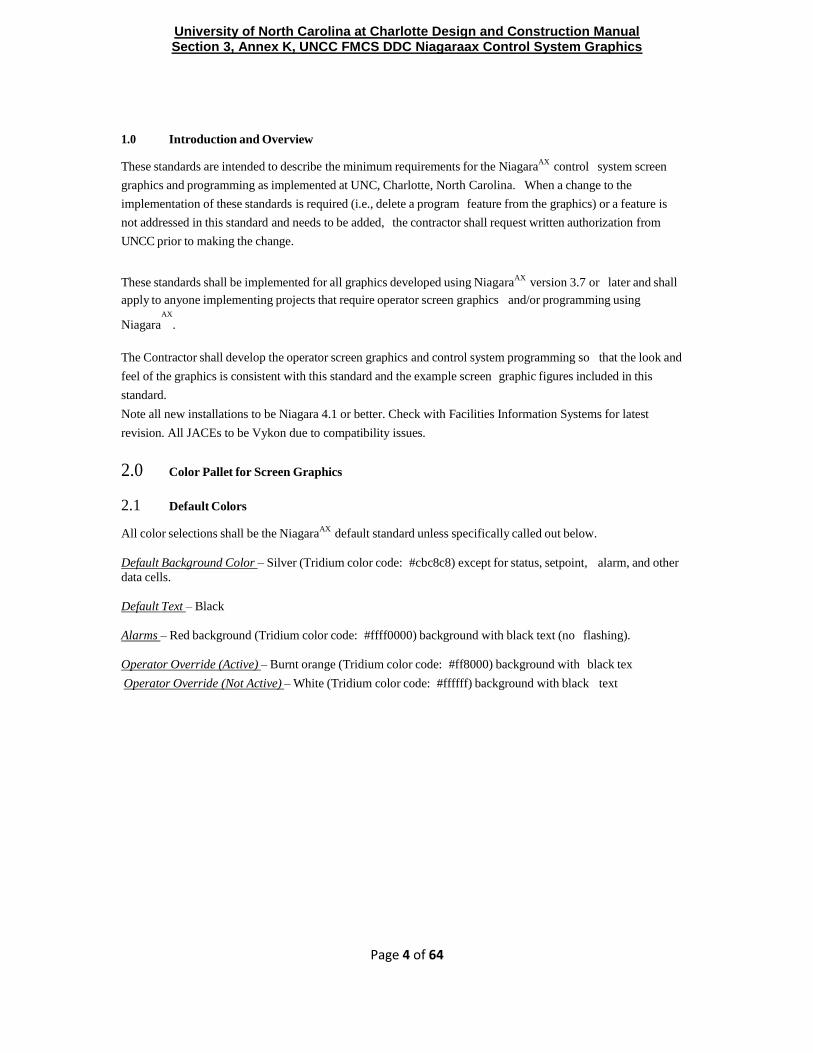
2.0 Color Pallet for Screen Graphics
2.1 Default Colors
All color selections shall be the NiagaraAX
default standard unless specifically called out below.
Default Background Color – Silver (Tridium color code: #cbc8c8) except for status, setpoint, alarm, and other
data cells.
Default Text – Black
Alarms – Red background (Tridium color code: #ffff0000) background with black text (no flashing).
Operator Override (Active) – Burnt orange (Tridium color code: #ff8000) background with black tex
Operator Override (Not Active) – White (Tridium color code: #ffffff) background with black text

University of North Carolina at Charlotte Design and Construction Manual Section 3, Annex K, UNCC FMCS DDC Niagaraax Control System Graphics
Page 5 of 64
Figure 1 – Example Air Handler Screen Graphic
2.2 General Information
General information includes descriptions or names of points such as Mixed Air Temp, Cold Water Valve,
Return Air CO2, etc. This information shall be shown as back text on a gold background (Tridium color code:
c 9 b d 8 d ). Upper and lower case text shall be used with the first letter in each word capitalized. Examples
of this are shown in Figure 1.
2.3 Process Status and Data
Process information and data includes temperatures, concentrations, status, and other process parameters that
the operator cannot set or override. This process information shall be black text on a white background. The
process data cells shall have a black border. All temperatures shall be reported with 1 decimal point. For
example the temperature would be displayed as 72.6ºF.
All CO2 sensor values shall be displayed with no decimal point. For example the CO2 concentration would be
displayed as 537 ppm. All percentages shall be displayed with 1 decimal point. For example, a valve would be
100.0%. All supply air pressures that are measured in inches of water column shall be displayed with 2 decimal
points. For example, 3.51 iwc.

University of North Carolina at Charlotte Design and Construction Manual Section 3, Annex K, UNCC FMCS DDC Niagaraax Control System Graphics
Page 6 of 64
2.4 Point Status
The NiagaraAX
colors for point status shall be the standard default for the system as listed below.
Point Status Background Color
(Tridium color code)
Foreground Color
(Tridium color code)
Alarm Red #ffff0000 Black #ff000000
Disabled Light gray #dddddd Coalish gray
Fault Orange (ffaa26) Black
Down Yellow (ffff00) Black
Stale Reddish gray (d6cbae) Black
Overridden Purple (d88aff) Clear
Unacknowledged alarm Clear Clear
2.5 Alarms
All alarms shall be shown as black text on a Red background. (Note: Red is not used in screen graphics
except to designate an alarm condition.) Where the alarm box includes text, the text is black. No other colors
are used for alarms. Alarms do not flash. Alarms shall be shown with a black outline. See Return Fan
Command in Figure 1.=
2.6 Set points
All set points that the operator can adjust are shown as black text on a white background with a triangle in the
right hand side, similar to all other process data. The border of the setpoint cell changes to blue when the
mouse pointer scrolls over the cell and is right clickable. Once an override value is entered for the setpoint the
background color shall change to a purple Tridium color code; d88aff ) with black text. The cell containing the
override value shall have a black border. See SFan HOA in Figure 1. And below
Occupancy Schedule
The button used to access the building occupancy schedule is shown as black text on a white background with a
triangle in the right hand side indicating the operator can change or adjust this parameter. See AHU 1 Schedule
in Figure 1.
2.7 Override Values
All fields that contain an active override value have black text on a burnt orange background. The cell shall
have a black border. Examples of this are shown for the Return Fan Override and Cold Water Valve overrides

University of North Carolina at Charlotte Design and Construction Manual Section 3, Annex K, UNCC FMCS DDC Niagaraax Control System Graphics
Page 7 of 64
in Figure 1.
2.8 Headers
The header as shown in Figure 1.is located in the px file/CustomHeader of the Sample station given to the
Contactor by UNCC Controls Dept or FIS. The Alarm icon will turn red if an Alarm is present and each alarm
console and alarm class will include the building name. The as builts and sequence of operation need to be in a
HTML format and linked to the documents icon. The home paged is to be linked to the Home icon. Also See
Figure 7 on page 20.
2.9 HOA Switch
The local hand-off-auto (HOA) switch for air handlers, fans, pumps, etc. shall be connected to the DDC to
show the position of this switch. The screen graphics colors to use for the HOA switch are listed below:
Hand – Magenta (Tridium color code: #ffff00ff) background with black text, with black border.
Off – White (Tridium color code: #ffffff) background with black text, with black border.
Auto – Green (Tridium color code: #40ff40) background with black text, with black border
Examples of the possible HOA indications is shown in Figure 1 above for the Return Fan HOA Status (OFF)
and for the Supply Fan HOA Status (HAND).
2.10 Air Flow Arrows
The flow direction of the air on the air handler screen graphic shall be indicated via green arrows. An
example of the arrows indicating the air flow direction is provided in the Figure 1 example air handler screen
graphic.
3.0 Fonts and Font Size
The fonts used to create the graphics shall be as listed below:
Main Headings – Aerial 18 point (white)
All other Text – Tahoma 12 point (black)
4.1 Standard Building Graphics Screens
The standard screen graphics for each building shall include the following (where appropriate). See Figure 1a below
Floor Plans; Mini Maps if needed (See Graphic example 2&3 ) and all floor plans need to hyperlink to each
other. All Vavs associated with that floor are put into a sub folder for that floor.
VAV Summary; Summaries should be keep to just one particular area and not made too large so loading time is
not a factor. Use additional px’s instead of a large summary (See Figure 4 for example)
Chilled Water/Hot Water Equip; This page will show the building's Chilled Water and Hot Water equipment as
installed in the building where applicable.
AHU/RTU; this page will show the building's AHU and RTU equipment as installed in the building where
applicable.
Metering; all building Meters including but not limited to Electric, Water, Gas and BTU meters, use separate px
pages as tabbedpane take a longer time to load.

University of North Carolina at Charlotte Design and Construction Manual Section 3, Annex K, UNCC FMCS DDC Niagaraax Control System Graphics
Page 8 of 64
This page will show the building's Chilled Water and Hot Water equipment as installed in the building where
applicable.
Schedules; All Equipment schedules are to be set up according to UNCC specifications.
Alarms; there will be a minimum of 4 Alarm Classes, Each Alarm Class will have the building name and then the
alarm class ie: Friday Critical Alarms. The 4 alarm classes will be BldgNameCriticalAlarms,
BldgNameNonCriticalAlarms, BldgNameMaintananceAlarms and BldgNameNetworkAlarms. There will be 5
Alarm consoles one for each class and one where all four alarm classes come together with corresponding names
along with the building name
Figure 1a. Example Building Navigation page
Figure 2. Example Floor Plan Screen Graphics

University of North Carolina at Charlotte Design and Construction Manual Section 3, Annex K, UNCC FMCS DDC Niagaraax Control System Graphics
Page 9 of 64
Figure 3. Example Mini Map Floor Plan Screen Graphics
Figure 4. Example VAV Summaries Plan Screen Graphics
5.0 Screen Titles - Header
Each screen graphic shall display the building number and name. It is not required to display “UNCC” on each
screen graphic. Additionally the screen title should include for example the air handler and its zone. If no
distinct zone is identified for the air handler it is not required to include this information in the title. An
example header is shown in Figure 1 for Building 101. Also see Figure 7 on page 20.

University of North Carolina at Charlotte Design and Construction Manual Section 3, Annex K, UNCC FMCS DDC Niagaraax Control System Graphics
Page 10 of 64
6.0 Standard Buttons
Each screen graphic will be programmed to include “standard” buttons (where appropriate) to quickly navigate
to other graphic screens associated with that building. These standard buttons shall be located in the secondary
header near the top of the screen graphic.
6.1 Niagara Main Menu
This button will display a summary of all buildings that are integrated into the FMCS control system. The
“Niagara Main Menu” is a summary screen that shows all of the buildings that are tied into the FMCS DDC
(Building name and number) along with an icon with web link that when selected will bring up the summary
page screen graphic for that building. Note: The Niagara Main Menu will be located on the NiagaraAX
server when available.
Building Summary
This button will bring up the summary screen for this building. The summary screen shall include key
information about the building’s mechanical systems. The building summary will differ from building to
building based on the mechanical systems in that building.
6.2 As Built Drawings
This button provides a link to the as-built drawings files for this building. The as-built drawings will be stored as
HTML files on the NiagaraAX server. See Figure 7 on page 20.
6.3 Navigation Buttons
Navigation buttons shall be programmed into the secondary header to access other screens associated with the
building such as VAVs, Boilers, Chillers, etc. See Figure 7 on page 20.
7.1 Equipment Operational Status
In general the operational status of equipment shall be displayed on the screen graphics using standard
NiagaraAX
animations. Text and text status blocks shall not be used to display the equipment status unless an
operational animation is not available for the equipment. On summary screens where there are no depictions of
the equipment, the operational status will be displayed as described in the summary screen section of this
standard.
Animations should be used for the following equipment items to display status.
1. Fans (supply and return)
2. Pumps
3. Cooling Towers
4. Chillers
5. Dampers (Outside Air, Return Air, Exhaust/Relief, Mixed Air, Bypass/Face, Zone, Zone Hot
Deck/Cold Deck)
6. Valves/Coils (Cooling, Heating, Dual Temperature, Preheat, Reheat, Hot Deck/Cold Deck)
The building summary screen will indicate via colors, the status of the air handler systems. A colored circle in

University of North Carolina at Charlotte Design and Construction Manual Section 3, Annex K, UNCC FMCS DDC Niagaraax Control System Graphics
Page 11 of 64
front of the air handler ID indicates the operational status of that air handler.
Green – air handler is ON (not in alarm)
White – air handler is OFF (not in alarm)
Red – air handler is in Alarm (status is different from command)
8.1 Building Summary Screen
A summary screen shall be provided for each Building. Layout and content of the summary screen should be
similar to the Building 101 summary screen. The order in which the information and data is to be presented on
the summary screen is important and shall be as listed below and not be rearranged without approval. Items
at the top of the list should appear before items beneath it. Note that not all information listed below will apply to
every air handler. Note also that the actual condition (temperature, pressure, etc.) appears in the summary
before the set point for that condition. Multiple summary screens may be necessary for certain buildings due to
their size. Clicking on the air handler ID will bring up the screen graphic for that air handler.
Because of space limitations, the contractor shall use judgment to determine which information to show on the
summary screen but the order in which the information is listed in the summary table shall be in accordance
with the listing below.
Supply Air Fan Status (colored circles)
Air handler ID (AHU-1, AHU-2, etc.)
HOA Status
Freeze Stat Status
Smoke Sensor Status
CO2 Concentration
Supply Fan Command
Supply Air Temperature
Supply air Temperature Set Point
Space Air Temperature
Space Air Temperature Set Point
Return Air Fan Command
Return Air Fan Status
Return Air Temperature
Return Air Temperature Set Point
Static Pressure
Static Pressure Set Point
Dual Temperature Valve Position
Chilled Water Valve Position
Hot Water Valve Position

University of North Carolina at Charlotte Design and Construction Manual Section 3, Annex K, UNCC FMCS DDC Niagaraax Control System Graphics
Page 12 of 64
Filter Status
9.1 Occupancy Schedules
A separate occupancy schedule shall be programmed for each air handler in a building (unless otherwise
directed by the UNC Charlotte Project Coordinator). A button shall be programmed in the upper right corner
of the air handler screen graphic that will take the operator to the schedule input screen. The text shall be black
on a white background with a black border as shown below. The rollover color for the background shall be
cyan (Tridium color code #ff00ffff).
The occupancy schedules shall be programmed in accordance with the default occupancy schedule as listed in
Attachment E to this standard unless otherwise directed in writing from the UNC Charlotte Project Coordinator.
10.0 Schedule Status
The occupancy schedule status of the air handler will be shown on the screen graphic for the air handler in the
upper right corner of the screen, just below the “Air Handler Occupancy Schedule” button. The text shall be
labeled “Occupancy Status”. The schedule options text (“Occupied” or Unoccupied”) shall be displayed
either adjacent to or directly beneath the “Occupancy Status” as shown in Figure 1.
11.0 Outside Air Temperature
The outside air temperature shall be displayed in the UNC Charlotte approved header, in upper right hand corner of
the screen graphic. The text shall be “OAT”. The temperature value shall be black text on a white
background with a black border.
12.0 Screen Graphic Text Descriptions
In general, abbreviations should not be used on the screen graphics. Where because of space limitations a word
must be abbreviated the abbreviation must be in accordance with the approved abbreviation list. All text
descriptions shall be consistent (avoid using synonyms) and in accordance with the approved list. A copy of the
approved screen graphics abbreviations list is provided in Attachment D.
13.0 Air Handler Status and Controls
The air handler screen graphics should be programmed and displayed similar to the examples shown in Figure 1
for the supply air fan and return air fan.
13.1 Fan Command
The fan command text will be either “ON” or “OFF”. If the fan command is different from the fan status, the
Fan Command field will be in alarm (black text with red background). If not in alarm the fan command field
will be black text with a white background.
13.2 Fan Status
The fan status is displayed graphically with the rotating fan wheel and the fan discharge air movement. When
the fan status is off the graphic will indicate no fan movement.

University of North Carolina at Charlotte Design and Construction Manual Section 3, Annex K, UNCC FMCS DDC Niagaraax Control System Graphics
Page 13 of 64
13.3 Fan Override Status
The fan can be overridden to either ON or OFF. Therefore the override status will be either:
True – indicating that the fan is in override (ON or OFF) or
False – indicating that the fan is not in override (ON or OFF).
When the fan is in Override the background color will be burnt orange as shown for the return air fan in Figure 1.
Right clicking on the fan mode status field will bring up a pop-up window with the standard NiagaraAX
override
options.
14.0 Pump Status and Controls
All pump screen graphics should be programmed and displayed similar to an air handler (fan) with the
following three fields:
Pump Command
Pump Override
Pump HOA Status
14.1 Pump Command
The pump command will be either “ON” or “OFF”. If the pump command is different from the pump status,
the Pump Command field will be in alarm (black text with red background). If not in alarm the fan command
field will be black text with a white background.
14.2 Pump Status
The pump status is displayed graphically with the rotating pump impeller. When the pump status is off the
graphic will indicate no pump movement.
14.3 Pump Override
The pump can be overridden to either ON or OFF. Therefore the override status will be either:
True – indicating that the pump is in override or
False – indicating that the pump is not in override.
When the pump is in Override the background color will be burnt orange as shown for the return air fan in
Figure 1. Right clicking on the pump mode status field will bring up a pop-up window with the standard
NiagaraAX
override options.
15.1 FMCS Operator Override Capabilities
The screen graphics will be programmed to allow the operator to override certain operating parameters. For
those operating parameters where the operator can access and override, the cell background color will change to
cyan (Tridium color code #ff00ffff) when the mouse pointer scrolls over the cell. Once an override value is

University of North Carolina at Charlotte Design and Construction Manual Section 3, Annex K, UNCC FMCS DDC Niagaraax Control System Graphics
Page 14 of 64
entered for the setpoint the background color shall change to a burnt orange with black text and a black border.
Those parameters that the operators may override are listed below.
1. Occupancy Schedule
2. Dampers (Outside Air, Return Air, Exhaust/Relief, Mixed Air, Bypass/Face, Zone Hot
Deck/Cold Deck, Zone)
3. Damper Operating Mode (Economizer, Minimum Outside Air)
4. Supply Air Temperature Set Points
5. Return Air Temperature Set Points
6. Space Air Temperature Set Points
7. Zone Space Temperature Set Points
8. VAV Space Temperature Set Points
9. Global Zone Space Temperature Set Points
10. Global VAV Space Temperature Set Points
11. Hot Deck Temperature Set Points
12. Cold Deck Temperature Set Points
13. Boiler/Chiller Enable Set Points
14. Dual Temp Heating Set Points
15. Hot Water Return Set Points
16. Static Pressure Set Points
17. Economizer Set Points
18. Summer/Winter Change Over
19. Outside Air Flow Set Points
20. DX unit
21. Chiller System Enable Override
22. Boiler System Enable Override
23. Valves (Dual Temp, Cooling, Heating, Preheat, Reheat, Hot Deck/Cold Deck, Loop Bypass,
Loop, Chiller/Boiler Flow Valves)
24. Fans (Supply, Exhaust, Return)

University of North Carolina at Charlotte Design and Construction Manual Section 3, Annex K, UNCC FMCS DDC Niagaraax Control System Graphics
Page 15 of 64
25. Supply/Return Fan VFD Commands
26. Domestic Hot Water Boiler Commands
27. Chiller Commands
28. Boiler Commands
29. Fan Overrides/Damper Overrides
30. Steam Boiler Commands
31. VFD/VSD Speed Commands
32. Pumps (Chilled Water, Hot Water, Dual Temperature, Domestic Hot Water, Booster, Runaround
Pump)
33. Schedules (Building, Air Handler Unit, School Crossing Lights, Field Lights)
34. School Crossing Lights
35. Field Lights
36. Fan Mode/Air Handler Mode
37. Air Handler Schedule Mode (Building/AHU)
38. VAV (Min, Max, Fan Flow Set Points for Heating/Cooling)
16.0 Alarms
16.1 Summary Screen - Supply Air Fan Status Alarm
The Building Summary Screen will indicate when an air handler is in alarm. This alarm will be indicated when
the fan command is different from the fan status and will be shown as a red circle in front of the AHU. See
section 7.0.
16.2 Summary Screen – Sensor Alarms
The alarm is indicated for that temperature sensor on the screen graphic (black text on red background). Other
colors shall also be used to indicate status conditions of the temperature sensor as provided for in Section 2.4 of
this standard. These point status conditions include disabled, fault, down, stale, and null. Similar alarms and
status conditions of all sensors (temperature, pressure, humidity, CO2, etc) shall be provided on the screen
graphics.
Alarms shall be provided for control loops in accordance with the following criteria unless otherwise directed
by the sequence of operations or IJO Project Coordinator:
Temperature: Greater than +/- 3.0°F from setpoint.
Air pressure: Greater than +/- 0.30 iwc from setpoint
Water pressure: Greater than +/- 5.0 psi from setpoint
Humidity: Greater than +/- 10% RH from setpoint
University of North Carolina at Charlotte Design and Construction Manual Section 3, Annex K, UNCC FMCS DDC Niagaraax Control System Graphics
Page 16 of 64
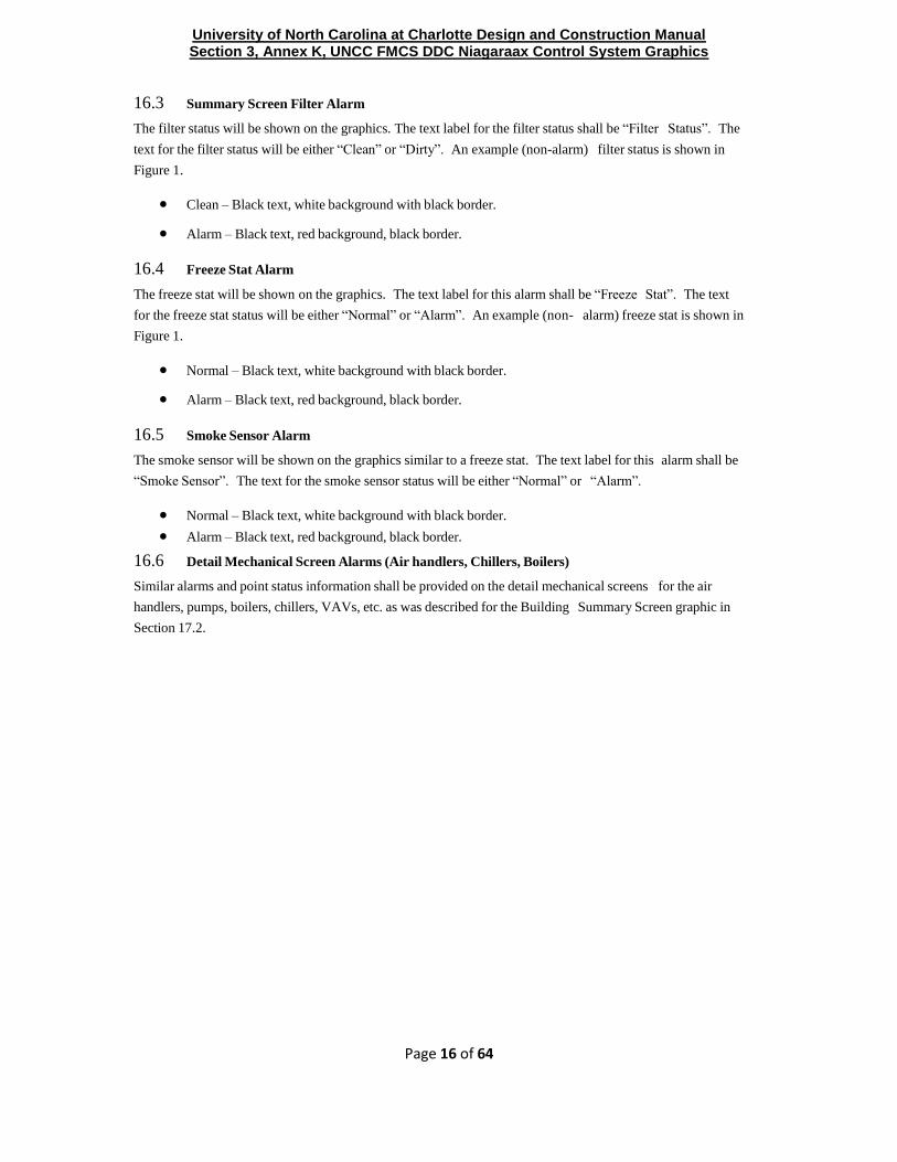
16.3 Summary Screen Filter Alarm
The filter status will be shown on the graphics. The text label for the filter status shall be “Filter Status”. The
text for the filter status will be either “Clean” or “Dirty”. An example (non-alarm) filter status is shown in
Figure 1.
Clean – Black text, white background with black border.
Alarm – Black text, red background, black border.
16.4 Freeze Stat Alarm
The freeze stat will be shown on the graphics. The text label for this alarm shall be “Freeze Stat”. The text
for the freeze stat status will be either “Normal” or “Alarm”. An example (non- alarm) freeze stat is shown in
Figure 1.
Normal – Black text, white background with black border.
Alarm – Black text, red background, black border.
16.5 Smoke Sensor Alarm
The smoke sensor will be shown on the graphics similar to a freeze stat. The text label for this alarm shall be
“Smoke Sensor”. The text for the smoke sensor status will be either “Normal” or “Alarm”.
Normal – Black text, white background with black border.
Alarm – Black text, red background, black border.
16.6 Detail Mechanical Screen Alarms (Air handlers, Chillers, Boilers)
Similar alarms and point status information shall be provided on the detail mechanical screens for the air
handlers, pumps, boilers, chillers, VAVs, etc. as was described for the Building Summary Screen graphic in
Section 17.2.

University of North Carolina at Charlotte Design and Construction Manual Section 3, Annex K, UNCC FMCS DDC Niagaraax Control System Graphics
Attachment B
Page 17 of 64
17.1 VAV Data
The following information shall be provided on the screen graphic for each VAV. An example VAV summary
screen graphic is shown in Figure 2.
Space Temperature
Space Temperature Set point
Supply Air Temp (from air handler)
Flow Set point
Actual Flow
Flow Minimum
Flow Maximum
Damper % Open
Reheat
18.0 Freeze Protection
All buildings integrated into the FMCS shall be programmed to prevent the building plumbing from freezing.
Freeze protection shall be accomplished by the DDC using the unoccupied night setbacks preprogrammed
functions in the control system. This function will turn on the air handler and maintain the space temperature to
the night setback temperature setpoint which shall be no less than 55°F.
The screen graphics shall be configured to provide indication to the FMCS operator when the air handler is in
the freeze protection mode. When in the freeze protection mode the screen graphics shall display the unoccupied
night setback temperature set point.
19.0 Point Naming and Numbering Convention
All points that are tied into the NiagaraAX control system shall be in accordance with the UNC Charlotte Niagara
AX Point Naming Convention. A listing of the point names, abbreviations and facets for the points is provided
in Attachment B.
20.0 Drawings and Documentation
The building summary screen graphic shall have a button in the header titled “As Built” that is programmed to
load a HTML file of the building control schematics. The HTML files will eventually be stored on the
NiagaraAX
server but until this server is installed and operational, the as-built drawings will be stored on the
Niagara R2 server.
21.1 Floor Plans
Floor plans shall be developed for each building that allows the FMCS operator to view pictorially the building

University of North Carolina at Charlotte Design and Construction Manual Section 3, Annex K, UNCC FMCS DDC Niagaraax Control System Graphics
Attachment B
Page 18 of 64
floor plan. The floor plan shall be appropriate to the type building and building function. Links between the
room and it’s associated air handler or VAV shall be configured into the floor plan graphic. The floor plan shall
clearly depict the following information:
Room numbers or names
Thermostat locations
Air handler locations
Mechanical rooms
IT Rooms
Meters
Lighting
Where the building is zone controlled, the floor plan shall indicate by colors, each zone. This includes using
colors to different the zones controlled by each air handler and/or by each VAV. The intent of this requirement
is to allow the operator to identify on the floor plan the location of the temperature problem and then to be able
to click on the floor plan affected area which would then be linked from the floor plan graphic web page to the
related VAV or AHU screen graphic web pages. An example floor plan showing the building 1680 layout
along with names, room numbers, and colors representing different VAV zones is shown below. The floor plan
graphic shall also show the location of all space temperature sensors (thermostats) along with the temperature
being measured by the sensor.

University of North Carolina at Charlotte Design and Construction Manual Section 3, Annex K, UNCC FMCS DDC Niagaraax Control System Graphics
Attachment B
Page 19 of 64
Note that the floor plan screen shall have the same headers and buttons as all other screens.
22.1 Photocell Operated Lights
Buildings that are equipped with light circuits that can be controlled from the DDC and that have local light
control photocells shall have the following information displayed on the screen graphics:
When the lights are directed to be on from the DDC the screen graphic shall show “ON”.
When the lights are directed to be off from the DDC the screen graphic shall show “OFF”
When the lights are controlled from the local photo cell the screen graphic shall show “PHOTOCELL”. Each
light circuit shall be identified on the screen graphic. The yellow shown in the lighting control column
indicates that the operator has override capability for these fields. A burnt orange color indicates the light
circuits that are in override. The status of the photocell (night or day shall also be shown on the light control
screen graphic. The following is an example of how the screen graphic for light controls should be designed:

University of North Carolina at Charlotte Design and Construction Manual Section 3, Annex K, UNCC FMCS DDC Niagaraax Control System Graphics
Attachment B
Page 20 of 64
Figure 5. Example Building Photocell Lights Screen
Note that the lighting control screen shall have the same headers and buttons as all other screens.
Figure 6. Example Building Header

University of North Carolina at Charlotte Design and Construction Manual Section 3, Annex K, UNCC FMCS DDC Niagaraax Control System Graphics
Attachment B
Page 21 of 64
Attachment B
Programming Standards
And
Acronyms and Abbreviations
1. Acronyms and Abbreviations
A/E Architect/Engineer
AHU (AHU1, AHU-2, etc.) – Air handler unit
ALX Activelogix
ANSI American National Standards Institute
ASC Application Specific Controller
BAS Building Automation System
BPOC Building Point Of Connection
CO Carbon monoxide
CO2 Carbon dioxide
DDC Direct Digital Control
DHCP Dynamic Host Configuration Protocol
DITSCAP Dod Information Technology Security Certification And Accreditation Process
ECIP Energy Conservation Investment Program
EIA Electronic Industries Alliance
ESPC Energy Savings Performance Contract
FAQ Frequently Asked Questions (Faqs)
FMC Energy Management Control System
FMCS Facility Management And Control System
FMD Facilities Maintenance Division
FPC Freely Programmable Lon Controllers
GPPC General Purpose Programmable Controller (Gppc)
GUI Graphical User Interface
HOA Hand-off-auto
HTML Hypertext Markup Language
HVAC Heating, Ventilating, And Air Conditioning
I/O Input/Output
IANA Internet Assigned Numbers Authority
ID/IQ Indefinite Delivery Indefinite Quantity
IDC Indefinite Delivery Contract
IDC Interoperable Digital Lon Controller
IDG Installation Design Guide
IM Instant Messaging
IP Internet Protocol
IT Information Technology
IWC (iwc) – Inches of water column
JCI Johnson Controls, Inc.

University of North Carolina at Charlotte Design and Construction Manual Section 3, Annex K, UNCC FMCS DDC Niagaraax Control System Graphics
Attachment B
Page 22 of 64
LAN Local Area Network
LDAP Lightweight Directory Access Protocol
LDP Local Display Panel
LNS Lonworks® Network Services
MAT Mixed air temperature
MOU Memorandum Of Understanding
MS Microsoft®
NAC Network Area Controller
NC North Carolina
NCT Network Configuration Tool
NOx Nitrogen oxides
NTP Notice To Proceed
O&M Operations And Maintenance
OI Operator Interface
OOT Object Oriented Technology
OSI Open Systems Interconnection
OWS Operator Workstation
PC Personal Computer
PDA Personal Digital Assistant
PDF Portable Document Format
PICS Product Interoperability Compliance Statement
PMI Power Measurement Interface
POC Point Of Contact
POT Portable Operator’s Terminal
PPM (ppm) – Parts per million
PVT Performance Verification Test
QC Quality Control
QV Quality Verification
RAT Return air temperature
RFP Request For Proposal
SAT Supply air temperature
Si Systeme Internationale (The “Metric System”)
SNMP Simple Network Management Protocol
SNVT Standard Network Variable Type
SOW Statement Of Work
SPA Space air temperature
TCP Transmission Control Protocol
TCS Temperature Control System
TP/FT Twisted-Pair/Free Topology
TR Technical Report
UDP User Datagram Protocol
UMC Utility Management Control System
UMCS Utility Monitoring And Control System
URL Universal Resource Locator
University of North Carolina at Charlotte Design and Construction Manual Section 3, Annex K, UNCC FMCS DDC Niagaraax Control System Graphics
Attachment B
Page 23 of 64
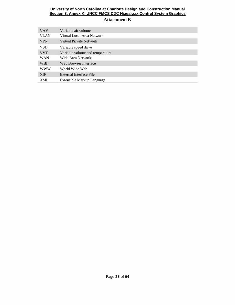
VAV Variable air volume
VLAN Virtual Local Area Network
VPN Virtual Private Network
VSD Variable speed drive
VVT Variable volume and temperature
WAN Wide Area Network
WBI Web Browser Interface
WWW World Wide Web
XIF External Interface File
XML Extensible Markup Language

University of North Carolina at Charlotte Design and Construction Manual Section 3, Annex K, UNCC FMCS DDC Niagaraax Control System Graphics
Attachment B
Page 24 of 64
2. Glossary of Terms
10Base-T
100Base-T
100Base-FX
1000Base-T
1000Base-SX
1000Base-LX
10GBase-T
Ethernet media and communication speeds. The number is communication speed in
Megabits per second (Mbps) or Gigabits per second (Gbps). “T” is twisted pair wire
usually Cat-6 or better), while “FX”, “SX”, and “LX” are fiber optic cable. Note that 10
Gigabit Ethernet is (as of 2006) an IEEE standard and 100 Gigabit Ethernet is in
development.
AGC
Application Generic Controller. A controller that comes from the factory with a
limited built-in application. It is programmed for the application (VAV box, fan coil,
etc.). It can be programmed through an LNS plug-in. It can be thought of as a cross
between an ASC and GPPC. These controllers should be certified by Lon Mark. An
AGC has a fixed program ID.
ASC
Application Specific Controller. A controller that has a built-in, fixed program to
execute a sequence for a specific hardware system,
e.g. a VAV box controller. An ASC has a fixed program ID.
BPOC
The Building Point of Connection (BPOC) is the point of connection between the FMCS
network backbone (an IP network) and the building control network backbone. The
hardware at this location that provides the connection is referred to as the BPOC
Hardware. In general, the term "BPOC Location" means the place where this connection
occurs, and "BPOC Hardware" means the device that provides the connection.
Sometimes the term "BPOC" is used to mean either and its actual meaning (i.e. location
or hardware) is determined by the context in which it is used.
Closed
The opposite of Open. A standard/protocol/specification where important details of
its implementation are not available to all interested parties. Closed standards are
closely controlled by the developing party and implementation of devices based on
them is generally limited to a small number of vendors.
Device A piece of hardware. See also 'Node'
DDC
Direct Digital Control, defined as control consisting of microprocessor based
controls with the control logic performed by software.
DDE
Dynamic Data Exchange, an inter-process communication (IPC) system built into the
Macintosh®, Microsoft® Windows®, and OS/2® operating systems. DDE enables
two running applications to share the same data.
DHCP
Dynamic Host Configuration Protocol is a protocol for automatically assigning IP
configuration information to clients from a central server.

University of North Carolina at Charlotte Design and Construction Manual Section 3, Annex K, UNCC FMCS DDC Niagaraax Control System Graphics
Attachment B
Page 25 of 64
FTP File Transfer Protocol is a common protocol used on the Internet for sending files.
Gateway
A device (usually a combination of software and hardware) that connects networks
using different communication protocols so that information can be passed from
devices on one network to the other. Gateways perform protocol conversion to
translate this information from one protocol to another.
GPPC
General Purpose Programmable Controller. A controller that can be programmed to
run any (within hardware limits) sequence and can
be set up as a controller for different hardware systems. Changes to the program result in a
different Program ID.
GUI
Graphical User Interface. A program interface that takes advantage of the computer's
graphics capabilities to make the program easier to use. A true GUI includes formats for
representing text and graphics.
HMI Human-Machine Interface. The means by which an operator interacts with an
automation system, often a GUI.
HTTP
HyperText Transfer Protocol, is the underlying protocol used by the World Wide Web.
HTTP defines how messages are formatted and transmitted, and what actions Web servers
and browsers should take in response to various commands.
Interoperability
The ability to integrate products from multiple vendors into flexible, functional
systems without the need to develop custom hardware, software, or tools.
Interoperable
This is closely related to Open standards and refers to the level of difficulty of integrating
components (or systems) from multiple vendors into a single system. Interoperability
needs to be considered from the perspective of hardware installation (will the parts
physically fit and interconnect?), communications (do the devices “speak the same
language”?), configuration and programming (is the same software tool used for different
vendor components?), maintainability (do the components have similar maintenance
procedures and requirements?), and operation (do the components have similar
functionality/ sequences and utilize the same operator interface?).
Open standards enhances/encourages interoperability because it allows multiple vendors
to utilize a common standard. A caveat: In many (if not all cases), when vendors use the
term interoperable, they do not mean interchangeable (in the sense of swapping out a
VAV box for an identical VAV box).
IP
Internet Protocol. IP is a protocol on the Internet and is concerned with addressing
and routing of data packets from their origin to the destination. Many other protocols
are used in the Internet (TCP, HTTP, etc), but IP is the key protocol the others run on
top of.
LAN Local Area Network, is a network for transferring data between computers or
other digital devices.

University of North Carolina at Charlotte Design and Construction Manual Section 3, Annex K, UNCC FMCS DDC Niagaraax Control System Graphics
Attachment B
Page 26 of 64
LNS®
LonWorks Network Service, is the database architecture that resides on the computer
attached to the LonWorks Network that is used to install and manage the Network. LNS
is a database that can be accessed by any LNS-based Network Configuration Tool and by
multiple users simultaneously.
LON Local Operating Network. Also used as a shorthand reference to the term LonWorks.
LonTalk®
A networking protocol developed by Echelon Corporation and recognized by
ANSI/CEA as ANSI/CEA-709.1-B. LonTalk implements layers 1-6 of the OSI
reference model.
LonWorks®
A networking platform (created by Echelon Corporation) that provides solutions to
numerous problems of designing, building, installing, and maintaining control networks.
LonWorks Router
A piece of equipment that allows ANSI/CEA-709.1-B communication and routing of
network variables over an ANSI/CEA-709.1-B network. See “Router”.
LonWorks LON to IP
Router
A piece of equipment that allows ANSI/CEA-709.1 communication and routing of
network variables over IP. Also known as an ANSI/CEA-852 router. See “Router”.
Network
A group of devices (computers, controllers, or other digital units) that are connected by
communication facilities, such as twisted-pair cabling, coAXial cable, fiber-optic cable,
or wireless means
Network Configuration Tool Software used to perform network management functions such as adding,
removing or relocating devices and establishing communication between devices.
Neuron® C A derivative of the C programming language specifically designed for developing
applications for the Neuron chip.
Neuron® chip
A chip that implements the ANSI/CEA-709.1 protocol. This chip is used by most
LonWorks devices for communication on the network. Many LonWorks devices also
use this chip for control functionality.
Node
A device (such as a computer or a controller) on a network that is capable of
communicating with other network devices via a networking protocol such as
NSI/CEA-709.1.
Open system
An Open system is characterized by the ability for any qualified third party entity to
readily modify, operate, upgrade, and perform retrofits on the system.
OWS
Operator Work Station, a type of computer-based GUI. An OWS is designed for use
by an operator whereas a technician or maintenance worker might have a different
computer and GUI with a different “look and feel”.
Peer-to-Peer A type of network where each node has equivalent capabilities and responsibilities
for network communication.
Plug-in Software used to configure an ASC that is run/executed from within a Network
Configuration Tool.

University of North Carolina at Charlotte Design and Construction Manual Section 3, Annex K, UNCC FMCS DDC Niagaraax Control System Graphics
Attachment B
Page 27 of 64
Proprietary Privately owned and controlled. Proprietary is the opposite of public domain.
Proprietary –
Government
procurement
In Government procurement regulations, a proprietary product is one that requires sole
source procurement.
Router
A device that connects two or more LANs. Routers are devices that provide network-
independent packet filtering and forwarding. They may also include bridge
functionality.
SNMP Simple Network Management Protocol
SNVT
Standard Network Variable Type; Pronounced 'snivet'. A standard format type
(maintained by LonMark International) used to define data information transmitted and
received by the individual LonWorks nodes. The term SNVT is used in two ways.
Technically it is the acronym for Standard Network Variable Type, and is sometimes used
in this manner. However, it is often used to indicate the network variable itself (i.e. it can
mean "a network variable of a standard network variable type"). In general, the intended
meaning should be clear from the context.
SOAP
Simple Object Access Protocol: A lightweight protocol for exchange of information in a
decentralized, distributed environment. It is an XML based protocol that consists of three
parts: an envelope that defines a framework for describing what is in a message and how
to process it, a set of encoding rules for expressing instances of application-defined data
types, and a convention for representing remote procedure calls and responses.
SQL
Structured query language, defined as a standardized query language for
requesting information from a database. There is an ANSI standard for SQL
Standard, De-facto
De-Facto standards are ‘standards of fact’, that is, standards that have been adopted by
an industry or a market. An example of a de-facto standard is Microsoft Word. While it
has not been adopted by a recognized standards organization, its market dominance
makes it the de-facto standard for word processing. Gray areas arise here over market
share and industry recognition.
Standard, De-jurie
De-Jurie standards (literally, ‘standards of law’) are those that have been adopted and
approved by some recognized standards organization, such as ASHRAE, IEEE, ASTM,
ISO, etc. ANSI/CEA-
709.1 is an example of a de-jurie standard. Gray areas can arise here over what
constitutes a standards body.

University of North Carolina at Charlotte Design and Construction Manual Section 3, Annex K, UNCC FMCS DDC Niagaraax Control System Graphics
Attachment B
Page 28 of 64
Standard, Proprietary
Proprietary standards are those that are owned and controlled by an organization not
generally recognized as a 'legitimate' standards body (they are often owned by a for-
profit organization). They frequently are considered to be, or to contain, intellectual
property of value to the owning body. Proprietary standards may be Open, closed, or
somewhere in between, though they tend to be more closed. The Microsoft Word
document format (.doc files) is an example of a closed proprietary standard
Transceiver A component or circuit that enables a hardware device to communicate
on a network.
VLAN
Virtual Local Area Network. A common means of keeping different networks separate
while existing on the same basewide LAN. Most modern Ethernet switches support
VLANs where the different ports on the switch are divided into separate logical
groupings. Ports in the same group can communicate with each other, while ports in
separate groups can’t. The ports in a common group form a VLAN within the larger
physical network. A single physical network may support many distinct VLANs.

University of North Carolina at Charlotte Design and Construction Manual Section 3, Annex K, UNCC FMCS DDC Niagaraax Control System Graphics
Attachment B
Page 29 of 64
3. Screen Graphic Abbreviations
The following abbreviation convention should be used for all screen graphics where appropriate.
a. Supply Air Temperature – SAT b. Supply Air Temperature Set Point – SAT SP c. Supply Air Flow - SAF d. Space Air Temperature – SPAT e. Space Air Temperature Set Point – SPAT SP f. Set Point – SP g. Occupancy Status – OS h. Air Handler Unit – AHU i. Outside Air – OA j. Outside Air Temperature – OAT k. Direct Expansion – DX l. Domestic Hot Water – DHW m. Boiler – BLR n. Hot Water – HW o. Hot Water Valve – HWV p. Chilled Water – CHW q. Chilled Water Valve – CHWV r. Fan Command – FAN CMD s. Fan Status – FAN STAT t. Fan Override – FAN OVRD u. Set Point Override – SP OVRD v. Freeze Protection – FREZ PROT w. Hot Water Supply Temperature – HWST x. Hot Water Return Temperature – HWRT y. Chilled Water Supply Temperature – CHWST z. Chilled Water Return Temperature – CHWRT aa. Command – CMD bb. Status – STS cc. Fan Start/Stop Control Switch – FAN S/S dd. Temperature – Temp

University of North Carolina at Charlotte Design and Construction Manual Section 3, Annex K, UNCC FMCS DDC Niagaraax Control System Graphics
Attachment B
Page 30 of 64
4. Definition of Display Names, Point Name and Facets
Display Name Point Name Facets
Actual Cooling Setpnt ACSP units=˚F precision=1
Actual Htg Setpnt AHSP units=˚F precision=1
Air Handling Unit AHU units=null precision=0
Air Quality AirQ units=ppm,precision=2,min=0.0,max=5000.0
Air Quality Flag AirQStatus truetext=On falsetext=Off
Airflow AirFlw units=cfm precision=1
Airflow Setpoint AirSet units=cfm precision=1
Alarm Alm truetext=true falsetext=false
Auxillary Space Temp AuxSpaceT units=˚F precision=1
Auxillary Temp AuxTemp units=˚F precision=1
Auxillary Temp AuxT units=˚F precision=1
Average Temperature AvgT units=˚F precision=1
Average Zone Temperature AvgZnT units=˚F precision=1
Bearing Oil Return Temp (# if needed) BrngOilRT(#) units=˚F precision=1
Bearing Oil Supply Temp BrngOilST units=˚F precision=1
Bldg Bldg units=null precision=0
Bldg Diff Press BDP units=psi precision=1
Bldg Flow (#) BldgFlow (# if
needed)
units=gpm precision=1
Bldg Static Press BStcPr units=in/wc precision=2
Bldg Static Press Setpoint BldStatPrSp units=in/wc precision=2
Boiler Blr units=null precision=0
Boiler Alarm BlrAlm truetext=ALARM falsetext=Normal

University of North Carolina at Charlotte Design and Construction Manual Section 3, Annex K, UNCC FMCS DDC Niagaraax Control System Graphics
Attachment B
Page 31 of 64
Boiler Command BlrCmd truetext=On falsetext=Off
Display Name Point Name Facets
Boiler Flame Fail BlrFlameFail truetext=ALARM falsetext=Normal
Boiler Flow Switch BlrFlowStat truetext=Flow falsetext=NoFlow
Boiler Modulating Valve BlrVlv units=% precision=0
Boiler Plant Enable BlrPlantEna truetext=Enabled falsetext=Disable
Boiler Pump Status BlrPStatus truetext=Running falsetext=Stopped
Boiler Status BlrStatus truetext=On falsetext=Off
Boiler Supply Temp BlrST units=˚F precision=1
Boiler Valve BlrVlv truetext=Open falsetext=Closed
Boiler Water Temp BlrWT units=˚F precision=1
Boilers Enabled Status BlrPlantStat truetext=Enabled falsetext=Disable
Booster Pump Speed BostrPO units=% precision=0
Booster Pump Status BostrPStatus truetext=Running falsetext=Stopped
Box Supply Temp DAT units=˚F precision=1
Building Differential Pressure BDP units=in/wc precision=2
Building Differential Pressure Low Limit BDPLL units=^in/wc precision=2
Building Pump # (number) Status BP#Status truetext=Running falsetext=Stopped
Building Pump Flow Switch BFlwStat truetext=Flow falsetext=NoFlow
Building Water Return Temp BldgRT units=˚F precision=1
Building Water Supply Temp BldgST units=˚F precision=1
Bypass Valve Command
BypVlv truetext=Open falsetext=Closed;
units=% precision=0
Calculated Cooling Setpoint ClgStPnt units=˚F precision=1

University of North Carolina at Charlotte Design and Construction Manual Section 3, Annex K, UNCC FMCS DDC Niagaraax Control System Graphics
Attachment B
Page 32 of 64
Charge GPM ChrgFlow

University of North Carolina at Charlotte Design and Construction Manual Section 3, Annex K, UNCC FMCS DDC Niagaraax Control System Graphics
Attachment B
Page 33 of 64
Display Name Point Name Facets
Chemical Treatment # Alarm ChemTrt#Alm
Chilled Water CHW units=% precision=0
Chilled Water Bypass Valve CHWBypVlv units=% precision=0
Chilled Water Bypass Valve Output CHWBypVlvO units=% precision=0
Chilled Water Differential Pressure CHWDP units=psi precision=0
Chilled Water Differential Pressure
Average
CHWDPAvg
units=psi precision=0
Chilled Water Differential Pressure
Setpoint
CHWDPSetP
units=psi precision=0
Chilled Water Pump # VFD CHWP#VFDO units=% precision=0
Chilled Water Pump Cmd CHWPCmd truetext=On falsetext=Off
Chilled Water Pump Status CHWPStat truetext=Running falsetext=Stopped
Chilled Water Return Flow CHWRFl units=gal/min precision=1
Chilled Water Return Temp CHWRT units=˚F precision=1
Chilled Water Setpnt CHWSP units=˚F precision=1
Chilled Water Setpnt (Leaving) LvCHWSetP units=˚F precision=1
Chilled Water Supply Flow CHWSFl units=gal/min precision=1
Chilled Water Supply Temp CHWST units=˚F precision=1
Chilled Water Valve CHWVlv units=% precision=0
Chiller CH truetext=Enabled falsetext=Disabled
Chiller # Chilled Water Differential
Pressure
CH#CHWDP
units=psi precision=0
Chiller # Chilled Water Differential
Pressure Switch
CH#CHWDPSw
truetext=Closed falsetext=Open
Chiller Alarm CHAlm truetext=ALARM falsetext=Normal
Chiller Amps CHAmps units=ampere (A) precision=2

University of North Carolina at Charlotte Design and Construction Manual Section 3, Annex K, UNCC FMCS DDC Niagaraax Control System Graphics
Attachment B
Page 34 of 64

University of North Carolina at Charlotte Design and Construction Manual Section 3, Annex K, UNCC FMCS DDC Niagaraax Control System Graphics
Attachment B
Page 35 of 64
Display Name Point Name Facets
Chiller Cmd CHCmd truetext=Enabled falsetext=Disabled
Chiller Cond Press CHCndPr units=psi precision=1
Chiller Enable CHEna truetext=Enabled falsetext=Disabled
Chiller KW CHKW units=kW precision=1
Chiller Plant Enable CHPlantEna truetext=Enabled falsetext=Disabled
Chiller Setpoint Reset CHWStPntRst units=null precision=0
Chiller Status CHStatus truetext=Running falsetext=Stopped
Chiller Volts CHVolts units=volt (V) precision=2
CO Level COLvl units=ppm precision=1
CO2 Alarm CO2Alm units=ppm precision=1
CO2 Level CO2Lvl units=ppm precision=1
Cold Deck ColdDeck
Cold Deck Humidity ColdDeckHum units=%RH precision=0
Cold Deck Temp ColdDeckT units=˚F precision=1
Coldest Zone Temp ColdestZnT units=˚F precision=1
Common Setpoint (Base) CmnStPnt units=null precision=0
Communication Lost Alarm
CommLostAlm truetext = Comm Lost falsetext=Comm
Normal
Communication Lost Alarm CommAlm truetext=Comm Lost falsetext=Comm Normal
Communication Status CommStatus truetext=Normal falsetext=No Comm
Compressor Comp#Status(#=Stage
number)
truetext=On falsetext=Off
Compressor # Safety Comp#Safety
(#=Stage number)
truetext=ALARM falsetext=Normal
Compressor Command Comp#Cmd(#=Stage
number)
truetext=Run falsetext=Off

University of North Carolina at Charlotte Design and Construction Manual Section 3, Annex K, UNCC FMCS DDC Niagaraax Control System Graphics
Attachment B
Page 36 of 64

University of North Carolina at Charlotte Design and Construction Manual Section 3, Annex K, UNCC FMCS DDC Niagaraax Control System Graphics
Attachment B
Page 37 of 64
Display Name Point Name Facets
Compressor Lockout CompLckOut truetext=LockedOut falsetext=Normal
Compressor Protection Circuit CompProtCrt truetext=Normal falsetext=Alarm
Condensate Switch Status CondensateStat truetext=true falsetext=false
Condenser Water CW
Condenser Water Pressure CWPress units=psi precision=1
Condenser Water Pump # Alarm CWP#Alm truetext=ALARM falsetext=Normal
Condenser Water Pump # Cmd CWP#Cmd truetext=On falsetext=Off
Condenser Water Pump # Runtime CWP#RunT units=nullprecision=1
Condenser Water Pump # Status CWP#Stat truetext=On falsetext=Off
Condenser Water Pump # VFD CWP#VFDO units=% precision=0
Condenser Water Pump Cmd CWPCmd truetext=On falsetext=Off
Condenser Water Pump Status CWPStat truetext=On falsetext=Off
Condenser Water Pump VFD CWPVFDO units=% precision=0
Condenser Water Return Flow CWRetFl units=gal/min precision=1
Condenser Water Return Temp CWRT units=˚F precision=1
Condenser Water Setpnt CWStPnt units=˚F precision=1
Condenser Water Supply Flow CWSFl units=gal/min precision=1
Condenser Water Supply Temp CWST units=˚F precision=1
Condenser Water Valve CWVlv units=% precision=0
Control Setpoint CtrlSp units=˚F precision=1
Control Temp CtrlTemp units=˚F precision=1
Controller Alarm CtrlAlm truetext=Alarm falsetext=Normal
Controller Status CtrlStat truetext=Online falsetext=Offline

University of North Carolina at Charlotte Design and Construction Manual Section 3, Annex K, UNCC FMCS DDC Niagaraax Control System Graphics
Attachment B
Page 38 of 64
Cool Switch ClgSw truetext=Auto falsetext=Off

University of North Carolina at Charlotte Design and Construction Manual Section 3, Annex K, UNCC FMCS DDC Niagaraax Control System Graphics
Attachment B
Page 39 of 64
Display Name Point Name Facets
Cooling
Clg truetext=Clg falsetext=Off OR units=%
precision=1
Cooling # Command Clg#Cmd (#=Stage
number)
truetext=On falsetext=Off
Cooling Capacity (%) ClgCap units=% precision=1
Cooling Cmd ClgCmd truetext=On falsetext=Off
Cooling Face & Bypass CCByp units=% precision=0
Cool Flag ClgStatus truetext=On falsetext=Off
Cooling Lockout Setpoint ClgLckSp units=˚F precision=1
Cooling Master Reference ClgMstrRef
Cooling Mode ClgMode truetext=On falsetext=Off
Cooling Request ClgReq truetext=ClgReq falsetext=NoClgReq
Cooling Setpoint - Unoccupied UnoccClgSp units=˚F precision=1
Cooling Setpoint Offset ClgSetPOff
Cooling Stages ClgStgs units=null precision=0
Cooling Tower ClgTwr truetext=On falsetext=Off
Cooling Tower # Fan Cmd ClgTwr#FCmd truetext=On falsetext=Off
Cooling Tower # Fan Status ClgTwr#FStat truetext=On falsetext=Off
Cooling Tower # Isolation Valve
Command
ClgTwr#IsoVlvCmd
truetext=Open falsetext=Closed
Cooling Tower # VFD ClgTwr#VFDO units=% precision=0
Cooling Tower Bypass Valve Output ClgTwrBypVlvO units=% precision=0
Cooling Tower Damper ClgTwrDpr units=% precision=0
Cooling Tower Hi Speed ClgTwrHiSpd truetext=HiSpeedOn falsetext=HiSpeedOff
Cooling Tower Lo Speed ClgTwrLoSpd truetext=LoSpeedOn falsetext=LoSpeedOff

University of North Carolina at Charlotte Design and Construction Manual Section 3, Annex K, UNCC FMCS DDC Niagaraax Control System Graphics
Attachment B
Page 40 of 64
Display Name Point Name Facets
Cooling Tower Pump Cmd ClgTwrPCmd truetext=On falsetext=Off
Cooling Tower Pump Status ClgTwrPStat truetext=On falsetext=Off
Cooling Tower Return Temp ClgTwrRetT units=˚F precision=1
Cooling Tower Sump High Limit ClgTwrSmpHL truetext=HL-ALARM falsetext=Normal
Cooling Tower Sump Low Limit ClgTwrSmpLL truetext=LL-ALARM falsetext=Normal
Cooling Tower Sump Temp ClgTwrSmpT units=˚F precision=1
Cooling Tower Supply Temp ClgTwrSupT units=˚F precision=1
Cooling Tower Vibration Alarm CT#VibeAlm truetext=VIB-ALARM falsetext=Normal
Cooling Valve ClgVlv units=% precision=0
Cooling Valve Command ClgVlvOut units=% precision=0
Current Limit CurrLim units=non precision=1
Damper Dpr
Damper Cmd DprCmd truetext=On falsetext=Off
Damper Command DprCmd truetext=On falsetext=Off
Damper Enable DprEna truetext=On falsetext=Off
Damper Manual Pos DprManPos units=% precision=0
Damper Mode (Manual Auto) DprMode 1=Manual 2=Auto
Damper Pos (VAV) DprPos units=% precision=0
Damper Status DprStat truetext=On falsetext=Off
Day Night Mode DayNtMode truetext=NIGHT falsetext=DAY
Deadband Db units=null precision=0
Differencial Pressure DiffPr units=psi precision=1
Differencial Pressure Setpoint DiffPrSp units=psi precision=1

University of North Carolina at Charlotte Design and Construction Manual Section 3, Annex K, UNCC FMCS DDC Niagaraax Control System Graphics
Attachment B
Page 41 of 64
Disch Air DA
Display Name Point Name Facets
Disch Air Dew Pnt DADewPnt units=˚F precision=1
Disch Air Flow DAFlow units=cfm precision=1
Disch Air Humidity DAHum units=%RH precision=0
Disch Air Static Press DAStaticPr units=in/wc precision=2
Disch Air Vel Press DAVelPr units=in/wc precision=2
Discharge Air Cooling Setpoint DaClgSp units=˚F precision=1
Discharge Air Duct Pressure Setpoint DADPSp units=in/wc precision=2
Discharge Air Heating Setpoint DaHtgSp units=˚F precision=1
Discharge Air Setpoint DATSp units=˚F precision=1
Discharge Air Smoke Detector Status DASmkDetStat truetext=Alarm falsetext=Normal
Discharge Air Temp DAT units=˚F precision=1
Discharge Air Temp Low Limit DATLL units=˚F precision=1
Dom Water Press DomWtrPr units=psi precision=1
Dom Water Pump Status DomWtrPStat ttruetext=On falsetext=Off
Drain Valve DrainVlv truetext=Open falsetext=Closed
Duct Smoke Det DuctSmokeDet truetext=ALARM falsetext=Normal
Duct Static Press DSPr units=in/wc precision=2
Economizer Econ truetext=Open falsetext=Closed
Economizer Status EconStat truetext=Enabled falsetext=Disabled
Economizer Switchover Setpoint EconSwSp units=˚F precision=1
Effective Setpoint EffSetP units=null precision=0
Element Communication Status ElemtCommStatus truetext=No falsetext=Yes

University of North Carolina at Charlotte Design and Construction Manual Section 3, Annex K, UNCC FMCS DDC Niagaraax Control System Graphics
Attachment B
Page 42 of 64
Emergency Lighting EMLTG truetext=On falsetext=Off
Emergency Shutdown EMShutdown truetext=ALARM falsetext=Normal
Display Name Point Name Facets
Emergency Stop EMStop truetext=Alarm falsetext=Normal
Enable Ena truetext=true falsetext=false
Energy Recovery Unit Command ERecovCmd truetext=Enables falsetext=Disabled
Energy Recovery Unit Command HRecovVlv truetext=Open falsetext=Closed
Enthalpy Enth units=btu/pound (BTU/lb)
Enthalpy Switch EnthSw truetext=true falsetext=false
Exh Air Damper ExAirDpr units=% precision=0
Exh Air Flow ExAirFlow units=cfm precision=1
Exh Fan ExF truetext=On falsetext=Off
Exh Fan Cmd ExFCmd truetext=true falsetext=false
Exh Fan Status ExFStatus truetext=true falsetext=false
Exhaust Fan Control ** ExFCmd truetext=On falsetext=Off
Exhaust Fan Status ** ExFStatus truetext=On falsetext=Off
Exhaust Fan VFD Speed Output ExFVFDO units=% precision=0
Face & Bypass Damper FaceBypDpr units=% precision=0
Failure Fail truetext=ALARM falsetext=Normal
Fan Fan truetext=On falsetext=Off

University of North Carolina at Charlotte Design and Construction Manual Section 3, Annex K, UNCC FMCS DDC Niagaraax Control System Graphics
Attachment B
Page 43 of 64
Fan # Cmd Fan#Cmd truetext=On falsetext=Off
Fan # VFD Alarm Fan#VFDAlm truetext=ALARM falsetext=Normal
Fan Cmd FanCmd truetext=On falsetext=Off
Display Name Point Name Facets
Fan Coil Unit FCU truetext=On falsetext=Off
Fan Control Offset FanCntOffst units=none precision=1
Fan Mode FanMode truetext=On falsetext=Off
Fan Occupied Mode Select FanOccModeSlt truetext=On falsetext=Off
Fan Speed FanSpd units=% precision=1
Fan Speed High FanSpdHi truetext=On falsetext=Off
Fan Speed Low FanSpdLo truetext=On falsetext=Off
Fan Status FanStatus truetext=On falsetext=Off
Fan Switch FanSw truetext=Auto falsetext=On
Fan Unoccupied Mode Select FanUnoccModeSlt truetext=On falsetext=Off
Fan VFD FanVFDO units=% precision=0
Filter Runtime FilterRunT units=hrs
Filter Status FilterStat truetext=true falsetext=false
Final Filter Status FinFilterStat truetext=true falsetext=false
Fire Alarm FireAlm truetext=true falsetext=false
Flow Override
FlowOvrd Enum
range(AUTO=1,OPEN=2,CLOSED=3,MIN-
4,Max=5)
Fluid Cooler Tower Fan 1 Command ClgTwrF1Cmd truetext=On falsetext=Off
Fluid Cooler Tower Fan 1 VFD Output ClgTwrVFD1O units=% precision=0
Fluid Cooler Tower Fan 2 Command ClgTwrF2Cmd truetext=On falsetext=Off
University of North Carolina at Charlotte Design and Construction Manual Section 3, Annex K, UNCC FMCS DDC Niagaraax Control System Graphics
Attachment B
Page 44 of 64
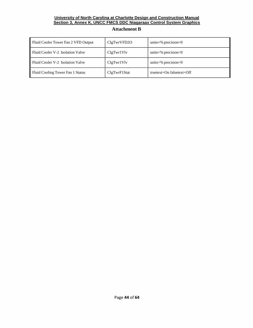
Fluid Cooler Tower Fan 2 VFD Output ClgTwrVFD2O units=% precision=0
Fluid Cooler V-2 Isolation Valve ClgTwr1Vlv units=% precision=0
Fluid Cooler V-2 Isolation Valve ClgTwr1Vlv units=% precision=0
Fluid Cooling Tower Fan 1 Status ClgTwrF1Stat truetext=On falsetext=Off

University of North Carolina at Charlotte Design and Construction Manual Section 3, Annex K, UNCC FMCS DDC Niagaraax Control System Graphics
Attachment B
Page 45 of 64
Display Name Point Name Facets
Fluid Cooling Tower Fan 2 Status ClgTwrF2Stat truetext=On falsetext=Off
Freeze Protection Circuit FrzProtCrt truetext=Alarm falsetext=Normal
Freeze Stat FrzStat truetext=Alarm falsetext=Normal
Frequency Frq
General Element Alarm GenlAlm truetext=Alarm falsetext=Normal
GPM Flow
Group Fan Occ Mode Sel GrpModeOccMode trueText=Auto,falseText=On
Group Mode Select GrpModeSel units=null,precision=2,min=0.0,max=4.0
Group Name GrpName
Group Number GrpNumber
Group Occupied Schedule GrpOccSched
Hand Hnd range=<0=Off, 1=InHand/Manual, 2=Auto>
Heat Ex HX truetext=On falsetext=Off
Heat Ex Bypass Valve HXBypVlv truetext=Open falsetext=Closed
Heat Ex Valve HXVlv units=% precision=0
Heat Flag HtgStatus truetext=On falsetext=Off
Heat Switch HtgSw truetext=Auto falsetext=Off
Heating
Htg truetext=true falsetext=false or units=%
precision=1
Heating Capacity (%) HtgCap units=% precision=1
Heating Command Htg#Cmd (#=Stage
number)
truetext=On falsetext=Off
Heating Enable HtgEna truetext=On falsetext=Off
Heating Lockout Setpoint HtgLckSp units=˚F precision=1

University of North Carolina at Charlotte Design and Construction Manual Section 3, Annex K, UNCC FMCS DDC Niagaraax Control System Graphics
Attachment B
Page 46 of 64
Heating Master Reference HtgMstrRef

University of North Carolina at Charlotte Design and Construction Manual Section 3, Annex K, UNCC FMCS DDC Niagaraax Control System Graphics
Attachment B
Page 47 of 64
Display Name Point Name Facets
Heating Mode HtgMode truetext=HtgReq falsetext=NoHtgReq
Heating Request HtgReq truetext=HtgReq falsetext=NoHtgReq
Heating Setpoint HtgStPnt units=˚F precision=1
Heating Setpoint Offset HtgSetPOff
Heating Stages HtgStgs units=null precision=0
Heating Stages In Total HtgStgsTot units=null precision=0
High DA Temperature Alarm HiDaTempAlm Normal,Alarm
High Zone HiZone
Hot Deck Humidity HDeckHum units=%RH precision=0
Hot Deck Temp HDeckT units=˚F precision=1
Hot Water Diff Press HWDiffPr units=psi precision=1
Hot Water Flow HWFlow units=gal/min precision=1
Hot Water Pump Status HWPStat truetext=On falsetext=Off
Hot Water Pump VFD Output HWPVFDO units=% precision=0
Hot Water Return Flow HWRFl units=% precision=0
Hot Water Return Temp HWRT units=˚F precision=1
Hot Water Supply Flow HWSFl units=gal/min precision=1
Hot Water Supply Temp HWST units=˚F precision=1
Htg Valve HtgVlv units
Htg/Clg Valve HtgClgVlv units=% precision=0
Humidifier Cmd HumCmd truetext=On falsetext=Off
Humidity Setpnt HumStPnt units=%RH precision=0
HVAC Mode HvacMode Enumerated point

University of North Carolina at Charlotte Design and Construction Manual Section 3, Annex K, UNCC FMCS DDC Niagaraax Control System Graphics
Attachment B
Page 48 of 64
Isolation Valve IsoVlv units=% precision=0
Display Name Point Name Facets
Kilowatt Hours KWH units=kWh precision=1
KW Demand KW units=kW precision=1
Leaving Water Temperature LeavWtrTemp units=˚F precision=1
Lighting LTG units=˚F precision=1

University of North Carolina at Charlotte Design and Construction Manual Section 3, Annex K, UNCC FMCS DDC Niagaraax Control System Graphics
Attachment B
Page 49 of 64

University of North Carolina at Charlotte Design and Construction Manual Section 3, Annex K, UNCC FMCS DDC Niagaraax Control System Graphics
Attachment B
Page 50 of 64
Display Name Point Name Facets
Make Up Air Unit MAU truetext=On falsetext=Off
Make Up Air Unit 1 Command MAU1Cmd truetext=On falsetext=Off
Make Up Air Unit 1 Status MAU1Stat truetext=On falsetext=Off
Make Up Air Unit 2 Command MAU2Cmd truetext=On falsetext=Off
Make Up Air Unit 2 Status MAU2Stat truetext=On falsetext=Off
Max Clg Setpnt MaxClgSp units=˚F precision=1
Max Flow Setpoint MaxFlowSp units=none precision=1
Max Htg Setpnt MaxHtgSp units=˚F precision=1
Max Zone Temp MaxZnT units=null,precision=2,min=-inf,Max=+inf
Mechanical Cooling Setpoint ClgStPnt units=˚F precision=1
Min Clg Setpnt MinClgSp units=˚F precision=1
Min Flow Setpoint MinFlowSp units=none precision=1
Min Heating Flow Setpoint MinHtgFlow units=none precision=1
Min Htg Setpnt MinHtgSp units=˚F precision=1
Min Zone Temp MinZnT units+null,precision=1,min=-inf,Max=+inf
Mixed Air Damper MaDprOut units=% precision=0
Mixed Air Damper Positional MaDprPos units=% precision=0
Mixed Air Damper Setpoint MADMinPos units=% precision=0
Mixed Air Dew Pnt MaDewPnt units=˚F precision=1
Mixed Air Enthalpy MaEnth units=btu/pound (BTU/lb)
University of North Carolina at Charlotte Design and Construction Manual Section 3, Annex K, UNCC FMCS DDC Niagaraax Control System Graphics
Attachment B
Page 51 of 64
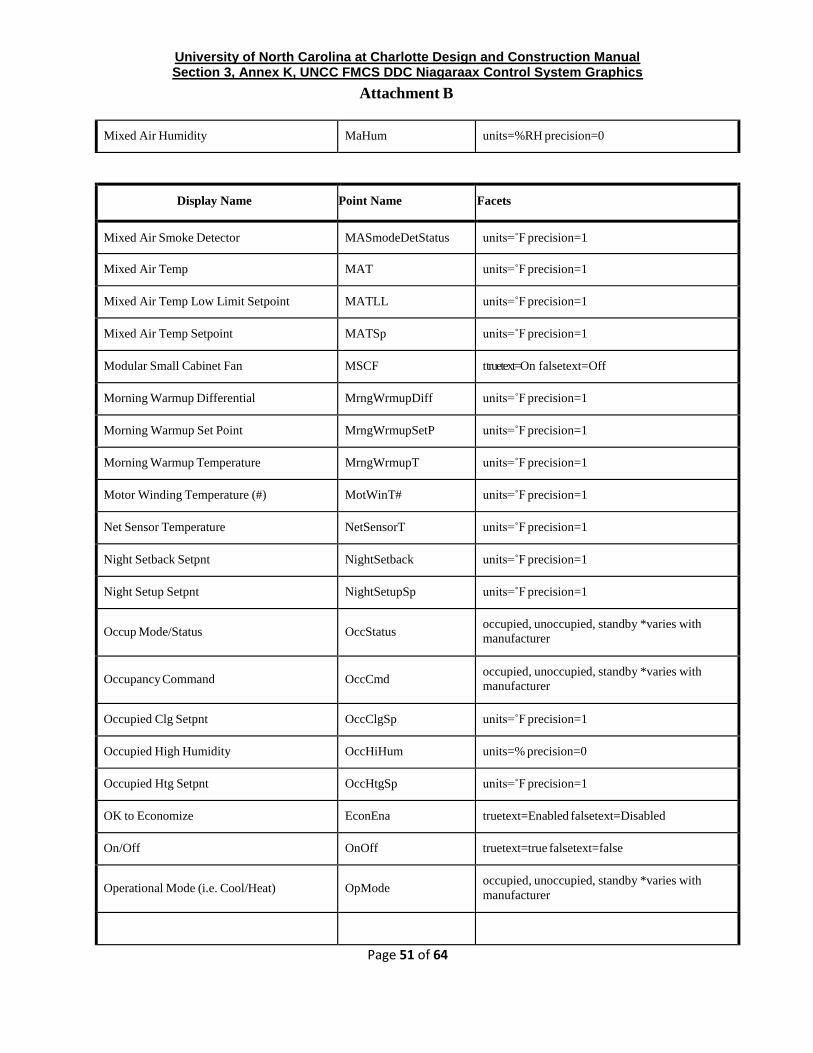
Mixed Air Humidity MaHum units=%RH precision=0
Display Name Point Name Facets
Mixed Air Smoke Detector MASmodeDetStatus units=˚F precision=1
Mixed Air Temp MAT units=˚F precision=1
Mixed Air Temp Low Limit Setpoint MATLL units=˚F precision=1
Mixed Air Temp Setpoint MATSp units=˚F precision=1
Modular Small Cabinet Fan MSCF ttruetext=On falsetext=Off
Morning Warmup Differential MrngWrmupDiff units=˚F precision=1
Morning Warmup Set Point MrngWrmupSetP units=˚F precision=1
Morning Warmup Temperature MrngWrmupT units=˚F precision=1
Motor Winding Temperature (#) MotWinT# units=˚F precision=1
Net Sensor Temperature NetSensorT units=˚F precision=1
Night Setback Setpnt NightSetback units=˚F precision=1
Night Setup Setpnt NightSetupSp units=˚F precision=1
Occup Mode/Status
OccStatus occupied, unoccupied, standby *varies with
manufacturer
Occupancy Command
OccCmd occupied, unoccupied, standby *varies with
manufacturer
Occupied Clg Setpnt OccClgSp units=˚F precision=1
Occupied High Humidity OccHiHum units=% precision=0
Occupied Htg Setpnt OccHtgSp units=˚F precision=1
OK to Economize EconEna truetext=Enabled falsetext=Disabled
On/Off OnOff truetext=true falsetext=false
Operational Mode (i.e. Cool/Heat)
OpMode occupied, unoccupied, standby *varies with
manufacturer

University of North Carolina at Charlotte Design and Construction Manual Section 3, Annex K, UNCC FMCS DDC Niagaraax Control System Graphics
Attachment B
Page 52 of 64
Outdoor Air Damper Position OADmpPos units=% precision=0

University of North Carolina at Charlotte Design and Construction Manual Section 3, Annex K, UNCC FMCS DDC Niagaraax Control System Graphics
Attachment B
Page 53 of 64
Display Name Point Name Facets
Outdoor Air Temperature OAT units=˚F precision=1
Outside Air Damper (2 Position) OADmpCmd truetext=Open falsetext=Closed
Outside Air Damper Minimum Position OADMinPos units=% precision=0
Outside Air Dew Pnt OADewPnt units=˚F precision=1
Outside Air Enthalpy OAEnth units=btu/pound (BTU/lb)
Outside Air Fan Start Stop OAFanCmd truetext=true falsetext=false
Outside Air Flow OAFlow units=cfm precision=1
Outside Air Flow Setpoint OAFlowSp units=cfm precision=1
Outside Air Humidity OAHum units=%RH precision=0
Outside Air Lockout Setpnt OATLckOut units=˚F precision=1
Outside Air Minimum Flow Setpoint OAMinFlowSp units=cfm precision=1
Override Command
OvrCmd occupied, unoccupied, standby *varies with
manufacturer
Override Duration (User Defined Time) OvrDuration units=min precision=1
Override Status OvrStat truetext=On falsetext=Off
Override Time Remaining OvrTmRemain units=min precision=1
Phase # Run Load Amps Phase#RLA units=amps precision=2
Photo Cell PTC truetext=true falsetext=false
Power Fail Status PwrFailStat truetext=PF falsetext=Normal
Pre Filter Status PreFilterStat truetext=Dirty falsetext=Clean
Pressure Press units=psi precision=1
Pri/Primary Pri units=null precision=0
Primary Air Flow PriAirFlw units=cfm precision=1
Primary Air Temperature PriAT units=˚F precision=1

University of North Carolina at Charlotte Design and Construction Manual Section 3, Annex K, UNCC FMCS DDC Niagaraax Control System Graphics
Attachment B
Page 54 of 64

University of North Carolina at Charlotte Design and Construction Manual Section 3, Annex K, UNCC FMCS DDC Niagaraax Control System Graphics
Attachment B
Page 55 of 64
Display Name Point Name Facets
Primary Pump Start Stop PPmp#Cmd truetext=On falsetext=Off
Pump # (number) Control P#Cmd truetext=On falsetext=Off
Pump # (number) Status P#Status truetext=On falsetext=Off
Pump # (number) VFD Output P#VFDO units=% precision=0
Refrig Exhaust Fan RefExFan truetext=On falsetext=Off
Refrig Monitor Alarm RefMonAlm truetext=ALARM falsetext=Normal
Refrig Shutdown RefShutdown
Reheat Temp RhtT units=˚F precision=1
Relative Humidity RH units=%RH precision=0
Relative Humidity Flag RHStatus truetext=ON falsetext=Off
Reliability of Inputs/Network Reliable truetext=Ok falsetext=Error
Relief Fan Command RLFCmd truetext=On falsetext=Off
Relief Fan Status RLFStat truetext=On falsetext=Off
Remote Adjust RemAdj truetext=On falsetext=Off
Remote Command RemCmd truetext=ON falsetext=Off
Return Air Damper RADpr units=% precision=0
Return Air Dew Pnt RADewPnt units=˚F precision=1
Return Air Enthalpy RAEnth units=btu/pound (BTU/lb)
Return Air Flow RAFlow units=cfm precision=1
Return Air Humidity RAHum units=%RH precision=0
Return Air Temp RAT units=˚F precision=1
Return Air Vel Press RAVelPr units=psi precision=1
Return Fan RetF truetext=On falsetext=Off
University of North Carolina at Charlotte Design and Construction Manual Section 3, Annex K, UNCC FMCS DDC Niagaraax Control System Graphics
Attachment B
Page 56 of 64
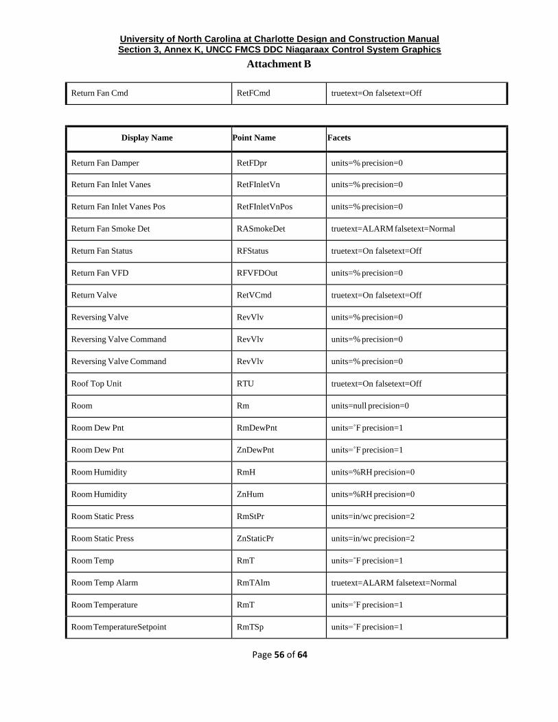
Return Fan Cmd RetFCmd truetext=On falsetext=Off
Display Name Point Name Facets
Return Fan Damper RetFDpr units=% precision=0
Return Fan Inlet Vanes RetFInletVn units=% precision=0
Return Fan Inlet Vanes Pos RetFInletVnPos units=% precision=0
Return Fan Smoke Det RASmokeDet truetext=ALARM falsetext=Normal
Return Fan Status RFStatus truetext=On falsetext=Off
Return Fan VFD RFVFDOut units=% precision=0
Return Valve RetVCmd truetext=On falsetext=Off
Reversing Valve RevVlv units=% precision=0
Reversing Valve Command RevVlv units=% precision=0
Reversing Valve Command RevVlv units=% precision=0
Roof Top Unit RTU truetext=On falsetext=Off
Room Rm units=null precision=0
Room Dew Pnt RmDewPnt units=˚F precision=1
Room Dew Pnt ZnDewPnt units=˚F precision=1
Room Humidity RmH units=%RH precision=0
Room Humidity ZnHum units=%RH precision=0
Room Static Press RmStPr units=in/wc precision=2
Room Static Press ZnStaticPr units=in/wc precision=2
Room Temp RmT units=˚F precision=1
Room Temp Alarm RmTAlm truetext=ALARM falsetext=Normal
Room Temperature RmT units=˚F precision=1
Room TemperatureSetpoint RmTSp units=˚F precision=1

University of North Carolina at Charlotte Design and Construction Manual Section 3, Annex K, UNCC FMCS DDC Niagaraax Control System Graphics
Attachment B
Page 57 of 64
Secondary Chilled Water Diff Press SCHWDiffPr units=psi precision=1
Secondary Chilled Water Flow SCHWFlow units=gal/min precision=1
Display Name Point Name Facets
Secondary Chilled Water Pump Status SCHWPStat truetext=On falsetext=Off
Secondary Chilled Water Return Temp SCHWRT units=˚F precision=1
Secondary Chilled Water Supply Temp SCHWST units=˚F precision=1
Secondary Condensor Pump Speed SCWP#Sp (#=pump
#)
units=Hz precision=1
Secondary Condensor Pump Speed Out SCWP#SO (#=pump
#)
units=Hz precision=1
Secondary Condensor Water Return Temp SCWRT units=˚F precision=1
Secondary Condensor Water Supply
Temp
SCWST
units=˚F precision=1
Secondary Pump Diff Press High Setpoint SPDPHSetP units=psi precision=1
Secondary Pump Diff Press Low Setpoint SPDPLSetP units=psi precision=1
Secondary Pump Ramp Timer SPRmpTmr units=null precision=0
Secondary Pump Start Stop SPmp#Cmd truetext=On falsetext=Off
Setpoint SetP units=null precision=0
Setpoint Adjust SetPAdj units=null precision=0
Setpoint High Limit SpHiLim units=˚F precision=1
Setpoint Low Limit SpLoLim units=˚F precision=1
Setpoint Offset Enable SpOffsetEna truetext=On falsetext=Off
Shut Down Status ShutDWNStat truetext=On falsetext=Off
SL Filter 1 Flow Switch Status SndFilter1Stat truetext=Error falsetext=Ok
SL Filter 2 Flow Switch Status SndFilter2Stat truetext=Error falsetext=Ok

University of North Carolina at Charlotte Design and Construction Manual Section 3, Annex K, UNCC FMCS DDC Niagaraax Control System Graphics
Attachment B
Page 58 of 64
SL Fliter 2 Command SndFilter2Cmd truetext=On falsetext=Off
SL Fliter Command SndFilter1Cmd truetext=On falsetext=Off
Smoke Damper Status SmokeDprStat truetext=Open falsetext=Closed

University of North Carolina at Charlotte Design and Construction Manual Section 3, Annex K, UNCC FMCS DDC Niagaraax Control System Graphics
Attachment B
Page 59 of 64
Display Name Point Name Facets
Smoke Det SmokeDet truetext=ALARM falsetext=Normal
Smoke Detector Status SmokeDetStat truetext=Error falsetext=Ok
Space Temp SpaceT units=˚F precision=1
Standby Clg Setpnt SbyClgSp units=˚F precision=1
Standby Htg Setpnt SbyHtgSp units=˚F precision=1
Static Press StaticPr units=in/wc precision=2
Static Press Setpoint StaticPrSp units=in/wc precision=2
Status Stat truetext=Error falsetext=Ok
Sump Pump Alarm SmpPAlm truetext=ALARM falsetext=Normal
Supply Air Dew Pnt SADewPnt units=˚F precision=1
Supply Air Flow SAFlow units=cfm precision=1
Supply Air Humidity SAHum units=%RH precision=0
Supply Air Reset SAReset units=˚F precision=1
Supply Air Static Press SAStaticPr units=in/wc precision=2
Supply Air Temp SAT units=˚F precision=1
Supply Air Temp Alarm SATAlm truetext=ALARM falsetext=Normal

University of North Carolina at Charlotte Design and Construction Manual Section 3, Annex K, UNCC FMCS DDC Niagaraax Control System Graphics
Attachment B
Page 60 of 64
Display Name Point Name Facets
Supply Air Vel Press SAVelPr units=in/wc precision=2
Supply Fan Alarm SFAlm truetext=Alarm falsetext=Normal
Supply Fan Alarm SFAlm Normal,Alarm
Supply Fan Cmd SFCmd truetext=On falsetext=Off
Supply Fan Cmd (2 Position) SFDprCmd truetext=On falsetext=Off
Supply Fan Command SFCmd truetext=On falsetext=Off
Supply Fan Damper (Linear) SFDprOut truetext=On falsetext=Off
Supply Fan Inlet Vanes SFInletVn units=% precision=0
Supply Fan Modulation SFVFDO units=% precision=0
Supply Fan Smoke Det SaSmokeDet truetext=Alarm falsetext=Normal
Supply Fan Status SFStatus truetext=On falsetext=Off
Supply Fan VFD Output SFVFDO units=% precision=0
System Enable SysEna truetext=Enabledfalsetext=Disabled
Tank Temp At Ft # TnkTmpFt# units=˚F precision=1
Temperature Temp units=˚F precision=1
Terminal Load TermLoad units=% precision=0
Timed Override TimedOvrride truetext=Yes falsetext=No
Thermo On/Off State_1(Mitsubishi) ThermoSt(Bit#) truetext=On falsetext=Off
Tower Twr truetext=On falsetext=Off
TRACER Control(Trane) TRACER truetext=Tracer falsetext=Local
Transfer Transfer truetext=On falsetext=Off
Unit Alarm UnitAlm truetext=Alarm falsetext=Normal
Unit Heater # UH truetext=On falsetext=Off
Unit Ventilator UV truetext=On falsetext=Off

University of North Carolina at Charlotte Design and Construction Manual Section 3, Annex K, UNCC FMCS DDC Niagaraax Control System Graphics
Attachment B
Page 61 of 64

University of North Carolina at Charlotte Design and Construction Manual Section 3, Annex K, UNCC FMCS DDC Niagaraax Control System Graphics
Attachment B
Page 62 of 64
Display Name Point Name Facets
Unocc Clg Setpnt UnoccClgSp units=˚F precision=1
Unoccupied Dehumidification UnoccDeHum truetext=Yes falsetext=No
Unoccupied High Humidity UnoccHiHum units=% precision=0
Unoccupied Status UnoccStatus truetext=On falsetext=Off
Unoccupied Status UnoccStatus truetext=On falsetext=Off
Valve Position VlvPos units=% precision=0
Valve Status VlvStat
Variable Frequency Drive VFD units=% precision=0
Variable Frequency Drive Alarm VFDAlm units=% precision=0
Variable Frequency Drive Frequency VFDFrq units=% precision=0
Variable Frequency Drive Output VFDO units=% precision=0
Ventilation Mode VentMode
VVT Box VVT
Warm/Cool Adjust WCAdj units=null precision=0
Warmest Zone Temp WarmestZnT units=˚F precision=1
Water Differential Pressure WDP units=psi precision=1
Water Flow WtrFl units=gal/min precision=1
Zone Zn units=null precision=0
Zone Damper ZnDprCmd units=% precision=0
Zone Damper Pos (Linear) ZnDprPosOut truetext=On falsetext=Off
Zone Damper Status ZnDprStat truetext=On falsetext=Off
Zone Demand ZnDmd DeltaF
Zone Humidity Setpnt ZnHumStpnt units=%RH precision=0
Zone Reheat Valve ZnRhtVlv units=% precision=0

University of North Carolina at Charlotte Design and Construction Manual Section 3, Annex K, UNCC FMCS DDC Niagaraax Control System Graphics
Attachment B
Page 63 of 64
Display Name Point Name Facets
Zone Setpnt ZnTStpt units=˚F precision=1
Zone State ZnState
Zone Temp ZnT units=˚F precision=1
Zone Temp Alarm ZnTAlm truetext=ALARM falsetext=Normal
Zone Temp Low Alarm ZnTLoAlm truetext=ALARM falsetext=Normal
AC Start Sequence StrtSeq truetext=On falsetext=Off

University of North Carolina at Charlotte Design and Construction Manual Section 3, Annex K, UNCC FMCS DDC Niagaraax Control System Graphics
Attachment B
5. Default Building Occupancy Schedule
Default Building Occupancy Schedule: The following occupancy schedules shall be programmed into the FMCS DDC unless otherwise directed by the UNCC.
Building Use Monday Tuesday Wednesday Thursday Friday Saturday Sunday
Administrative 0730-1800 0730-1800 0730-1800 0730-1800 0730-1800 By Appointment By Appointment
Type X 0600-2000 0600-2000 0600-2000 0600-2000 0600-2000 0600-2000 0600-2000
Type Y 0530-2130 0530-2130 0530-2130 0530-2130 0530-2130 0530-2130 0530-2130
Type Z By Appointment By Appointment By Appointment By Appointment By Appointment By Appointment By Appointment
Dorms Heating Heating Heating Heating Heating Heating Heating
0600-1700 65°F 0600-1700 65°F 0600-1700 65°F 0600-1700 65°F 0600-1700 65°F 0600-1700 65°F 0600-1700 65°F
1700-0600 72°F 1700-0600 72°F 1700-0600 72°F 1700-0600 72°F 1700-0600 72°F 1700-0600 72°F 1700-0600 72°F
Cooling Cooling Cooling Cooling Cooling Cooling Cooling
0600-1700 80°F 0600-1700 80°F 0600-1700 80°F 0600-1700 80°F 0600-1700 80°F 0600-1700 80°F 0600-1700 80°F
1700-0600 74°F 1700-0600 74°F 1700-0600 74°F 1700-0600 74°F 1700-0600 74°F 1700-0600 74°F 1700-0600 74°F