Embed Size (px)
Citation preview
www.elsevier.com/locate/cplett
Chemical Physics Letters 396 (2004) 420–423
Anisotropic electrical properties of semiconductive Bi2S3nanorod filled ferroelectric polyvinylidene fluoride
Yang Shen, Ce-Wen Nan *, Ming Li
Department of Materials Science and Engineering, State Key Lab of New Ceramics and Fine Processing, Tsinghua University,
Tsinghua Park, Beijing 100084, China
Received 2 July 2004; in final form 18 August 2004
Abstract
A novel ferroelectric polymer composite with semiconductive Bi2S3 nanorods loaded in ferroelectric polyvinylidene fluoride
(PVDF) is prepared via a simple solution-cast method. A high dielectric constant of over 100, which is over 10 times larger than
that of the polymer matrix, is obtained in the percolative composite with a low loading concentration of 0.5 vol% Bi2S3 nanorods.
The preferential orientations of Bi2S3 nanorods in the polymer PVDF lead to anisotropy of electrical properties of the composite
along the directions parallel (in-plane) and perpendicular (out-of-plane) to the sample surface. The in-plane dielectric constant of the
percolative composite sharply decreases at low frequency, and this anisotropy becomes small at high frequency.
� 2004 Elsevier B.V. All rights reserved.
1. Introduction
Recently, ferroelectric and/or dielectric polymer-
based composites filled with inorganic particles such as
ferroelectric ceramic [1] and metal particles [2], have at-
tracted much attention due to their enhanced perform-
ance, easy processing and flexibility. One interesting
feature of such polymer-based composites is their en-
hanced dielectric constants over that of the polymer ma-
trix, which makes them attractive for technological usein capacitors and energy storage devices [1,3]. In partic-
ular, the effective dielectric constants of the composites
could be greatly enhanced over that of the polymer ma-
trix [2], which is attributed to the percolation transition
at a critical metallic concentration [2,4,5]. Such percolat-
ive composites, however, could exhibit large dielectric
loss due to the existence of a conducting metallic path
just above the percolation threshold, and the dramati-cally enhanced conductivity just above the percolation
0009-2614/$ - see front matter � 2004 Elsevier B.V. All rights reserved.
doi:10.1016/j.cplett.2004.08.088
* Corresponding author. Fax: +86 10 62773587.
E-mail address: [email protected] (C.-W. Nan).
threshold makes the loss increase sharply. In order to re-
duce the dielectric loss of the percolative compositesfilled with metal particles, metallic fillers could be re-
placed with semiconductor ones whose conductivity is
comparatively lower than that of the metallic fillers.
By using semiconductor particles as fillers, the conduc-
tivity of the composites could be lower at the percola-
tion threshold and thus the dielectric loss decreases as
well. Semiconductor particles are usually used as fillers
to improve the photovoltaic properties or non-linearoptical properties of polymers [6]. Bismuth sulfide
(Bi2S3), a direct-band-gap semiconductor with Eg of
1.3 eV [7], is used as fillers in this work. Bi2S3 was dis-
persed into a conjugated polymer matrix as acceptor
to improve photovoltaic properties of the polymer [8].
In this work, by using semiconductive Bi2S3 as fillers,
we present a novel dielectric/ferroelectric polymer-based
composite.It has been well known that the shape of fillers is an-
other important parameter for such percolative com-
posites. For example, carbon nanotubes [9] and
carbon fibers [10] with large aspect ratios have been
Y. Shen et al. / Chemical Physics Letters 396 (2004) 420–423 421
used as fillers to approach dramatically low percolation
threshold. These composites consisting of the fillers
with large aspect ratios could be anisotropic and the
anisotropy in their properties could be controlled both
rheologically [11] and magnetically [12]. In the present
work, Bi2S3 nanorods with large aspect ratio are usedand filled into a ferroelectric polymer, polyvinylidene
fluoride (PVDF). With only relatively low concentra-
tion of Bi2S3 nanorods, the percolative composites
form, and the anisotropy in the electrical properties
of the composites are observed. The electrical behavior
of the percolative composites could be explained by the
percolation theory and anisotropic microstructure of
the composites.
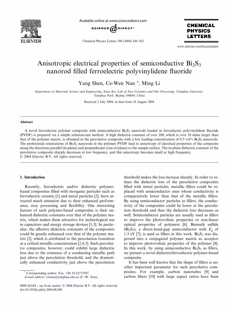
Fig. 1. (a) Cross-section and (b) surface micrographs of the Bi2S3/
PVDF composite sample with 5 vol% Bi2S3 nanorods.
2. Experimental procedure
Bi2S3 nanorods with 10–20 lm in length and 100–200
lm in diameter were synthesized by a solvothermal meth-
od [13]. The aspect ratio of these nanorods is approxi-
mately 100. The composite samples were prepared by asimple solution-cast method. A desired amount of Bi2S3nanorods was first ultrasonicated in 20 mlN,N-dimethyl-
formamide (DMF) solvent for 2 h, followed by adding a
certain amount of PVDF powder. The volume fractions
of Bi2S3 and the PVDF matrix in the composite samples
were determined in the normalway from theirweight frac-
tions and densities which are 7.7 and 1.79 g/cm3, respec-
tively, for Bi2S3 and PVDF. The mixture was thenheated and stirred until the PVDF powder was dissolved
thoroughly in theDMFsolvent.The resultant solutionwas
poured onto a glass substrate and slowly dried at 80 �Cuntil the solvent was completely evaporated from the
composite samples. The resultant film was then folded,
put into a disk mold and hot-pressed at 200 �C and 10
MPa for 15 min. Silver electrodes were painted on both
sides of the samples. Electrical properties, along the direc-tions both parallel (in-plane) and perpendicular (out-of-
plane) to the sample surface,weremeasured by employing
a HP 4194A impedance/gain-phase analyzer in the fre-
quency ranges of 100Hz to 40MHz at room temperature.
3. Results and discussion
The cross-section micrograph (Fig. 1a) and surface
micrograph (Fig. 1b) of the composite samples demon-
strate that the Bi2S3 nanorods are homogeneously dis-
persed into the PVDF matrix without serious
aggregation. However, the majority of the nanorods have
preferential orientations in the direction parallel to the
sample surface. These preferential orientations can be as-
cribed to the processing method used here. During thesolution-casting and solvent evaporation process, the
Bi2S3 nanorods with large aspect ratio trend to lie down
and take preferential orientations in the film plane. Then,
a pressure at 200 �C (a little higher than the melting point
of PVDF, i.e., about 180 �C) was added along the direc-
tion perpendicular to the film plane when the film was
folded and hot pressed into a disk-shaped sample, which
could further strengthen the preferential orientations of
the Bi2S3 nanorods in the thermoplastic PVDF matrix.The preferential orientations of the Bi2S3 nanorods
mostly take place during the solvent evaporation, which
is a slow process to assure the formation of a good film
without pores. Too fast solvent evaporation at higher
temperature than 80 �C would lead to a lot of pores in
the film and also affect the preferential orientations of
the Bi2S3 nanorods. Post-hot-pressing temperature and
pressure also have an effect on the anisotropy. Low hot-pressing temperature (e.g., less than 180 �C) and pressure
cannot densify the folded films into a disk-shaped sample
and strengthen the preferential orientations of the Bi2S3nanorods. But high hot-pressing temperature (e.g., higher
than 200 �C) andpressurewould greatly increase difficulty
of the high-quality sample preparation. The preferential
orientations could lead to anisotropy of the composites
and thereby different behavior along the directions paral-lel and perpendicular to the sample surface.
Fig. 2 shows the low-frequency electrical behavior for
the Bi2S3/PVDF composites measured along these
two directions (e.g., in-plane and out-of-plane). The
422 Y. Shen et al. / Chemical Physics Letters 396 (2004) 420–423
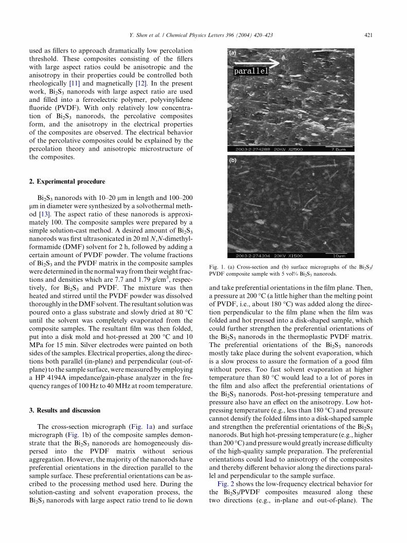
measured conductivity (Fig. 2a) demonstrates that the
percolation thresholds are quite low but different along
the two directions. Along the parallel direction, the per-
colation threshold of the in-plane conductivity is around
fcpa � 0.004, which is about over one order of magnitude
lower than that along the perpendicular direction, i.e.,fcpe � 0.08. This difference can be ascribed to the prefer-
ential orientations of the Bi2S3 nanorods (Fig. 1). The
0.00 0.02 0.04 0.06 0.08 0.10
10-10
10-9
10-8
σ (S
/cm
)
Perpendicular
Parallel
0.00 0.02 0.04 0.06 0.08 0.10
0
40
80
120
160
ε
Perpendicular
Parallel
0.00 0.02 0.04 0.06 0.08 0.100.0
0.2
0.4
0.6
Tan
δ
Volume fraction of Bi2S3
Volume fraction of Bi2S3
Volume fraction of Bi2S3
Perpendicular
Parallel
(a)
(b)
(c)
Fig. 2. (a) Conductivity, (b) dielectric constant and (c) dielectric loss at
100 Hz for the Bi2S3/PVDF composites measured along the directions
parallel (in-plane) and perpendicular (out-of-plane) to the sample
surfaces.
nanorods with large aspect ratio connect with each other
to form a percolation path more easily than spheres, so
both percolation thresholds, fcpa and fcpe, could be re-
duced to quite low values. The preferential orientations
of the Bi2S3 nanorods could also make fcpe (or fcpa) lar-
ger (or lower) than the value corresponding to an iso-tropic case with random orientation of the nanorods.
The measured dielectric constants (Fig. 2b) more
clearly illustrate the difference along the different direc-
tions. Of interest, the divergent behavior of the effective
dielectric constant in the vicinity of the percolation
threshold is observed along the parallel direction, as pre-
dicted by the power law [4]:
e ¼ e0fcpa � ffcpa
����
����
�q
; ð1Þ
where e0 is the dielectric constant of the PVDF polymer
matrix, f is the volume fraction of the Bi2S3 nanorods,
and q is the critical exponent of about 1. Just below
the percolation threshold, the fitting of Eq. (1) to the
data gives fcpa � 0.005, and q � 0.72. As seen, the in-
plane dielectric constant can be enhanced to over 100
by adding a very small amount of Bi2S3 nanorods. As
the volume fraction of Bi2S3 is larger than about 0.06,the anisotropy in the electrical properties of the compos-
ites becomes very weak, since the percolation paths form
across the whole samples. At low frequency, the conduc-
tion is a dominative loss mechanism, so the dielectric
loss increase as the conductivity increases near the per-
colation threshold (Fig. 2c).
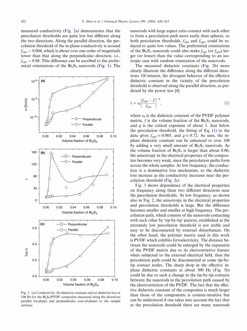
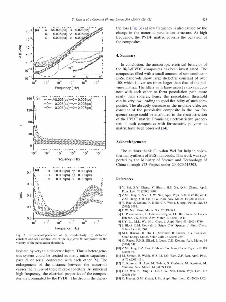
Fig. 3 shows dependence of the electrical properties
on frequency along these two different directions nearthe percolation thresholds. At low frequency, as shown
also in Fig. 2, the anisotropy in the electrical properties
and percolation thresholds is large. But the difference
becomes smaller and smaller at high frequency. The per-
colation path, which consists of the nanorods contacting
with each other by �tip-by-tip� pattern, established at the
extremely low percolation threshold is not stable and
easy to be disconnected by external disturbances. Onthe other hand, the polymer matrix used in this work
is PVDF which exhibits ferroelectricity. The distance be-
tween the nanorods could be enlarged by the expansion
of the PVDF matrix due to its electrostrictive feature
when subjected to the external electrical field, thus the
percolation path could be disconnected at some tip-by-
tip contact nodes. The sharp drop in the effective in-
plane dielectric constants at about 300 Hz (Fig. 3b)could be due to such a change in the tip-by-tip contacts
between the nanorods in the percolation path caused by
the electrostriction of the PVDF. The fact that the effec-
tive dielectric constant of the composites is much larger
than those of the components is counter-intuitive but
can be understood if one takes into account the fact that
at the percolation threshold there are many nanorods
102
103
104
105
106
107
10-11
10-10
10-9
10-8
10-7
10-6
10-5
102 103 104
10-10
10-9σ (S
/cm
)
Frequency ( Hz)
f=0.003(pa) 0.003(pe)0.005(pa) 0.005(pe)0.007(pa) 0.007(pe)
102
103
104
105
106
107
0
40
80
120
160
ε
Frequency ( Hz)
f=0.003(pa) 0.003(pe)0.005(pa) 0.005(pe)0.007(pa) 0.007(pe)
102
103
104
105
106
107
0.0
0.1
0.2
0.3
0.4
Tan
δ
Frequency ( Hz)
f=0.003(pa) 0.003(pe)0.005(pa) 0.005(pe)0.007(pa) 0.007(pe)
(a)
(b)
(c)
Fig. 3. Frequency-dependence of: (a) conductivity, (b) dielectric
constant and (c) dielectric loss of the Bi2S3/PVDF composites in the
vicinity of the percolation threshold.
Y. Shen et al. / Chemical Physics Letters 396 (2004) 420–423 423
isolated by very thin dielectric layers. Thus a heterogene-
ous system could be treated as many micro-capacitors
parallel or serial connected with each other [5]. Theenlargement of the distance between the nanorods
causes the failure of these micro-capacitors. At sufficient
high frequency, the electrical properties of the compos-
ites are dominated by the PVDF. The drop in the dielec-
tric loss (Fig. 3c) at low frequency is also caused by the
change in the nanorod percolation structure. At high
frequency, the PVDF matrix governs the behavior of
the composites.
4. Summary
In conclusion, the anisotropic electrical behavior of
the Bi2S3/PVDF composites has been investigated. The
composites filled with a small amount of semiconductor
Bi2S3 nanorods show large dielectric constant of over
100, which is over ten times larger than that of the pol-
ymer matrix. The fillers with large aspect ratio can con-nect with each other to form percolation path more
easily than spheres, hence the percolation threshold
can be very low, leading to good flexibility of such com-
posites. The abruptly decrease in the in-plane dielectric
constant of the percolative composite in the low fre-
quency range could be attributed to the electrostriction
of the PVDF matrix. Promising electrostrictive proper-
ties of such composites with ferroelectric polymer asmatrix have been observed [14].
Acknowledgements
The authors thank Guo-dan Wei for help in solvo-
thermal synthesis of Bi2S3 nanorods. This work was sup-
ported by the Ministry of Science and Technology ofChina through 973-Project under 2002CB613303.
References
[1] Y. Bai, Z.Y. Cheng, V. Bharti, H.S. Xu, Q.M. Zhang, Appl.
Phys. Lett. 76 (2000) 3804.
[2] Z.M. Dang, Y. Shen, C.W. Nan, Appl. Phys. Lett. 81 (2002) 4814;
Z.M. Dang, Y.H. Lin, C.W. Nan, Adv. Mater. 15 (2003) 1625.
[3] Y. Rao, S. Ogitani, P. Kohl, C.P. Wong, J. Appl. Polym. Sci. 83
(2002) 1084.
[4] C.W. Nan, Prog. Mater. Sci. 37 (1993) 1.
[5] C. Pecharroman, F. Esteban-Betegon, J.F. Bartolome, S. Lopez-
Esteban, J.S. Moya, Adv. Mater. 13 (2001) 1541.
[6] S.Y. Lu, M.L. Wu, H.L. Chen, J. Appl. Phys. 93 (2003) 5789.
[7] J. Black, E.M. Conwell, L. Seigle, C.W. Spencer, J. Phys. Chem.
Solids 2 (1957) 240.
[8] M.E. Rincon, H. Hu, G. Martinez, R. Suarez, J.G. Banuelos,
Solar Energy Mater. Solar Cells 77 (2003) 239.
[9] O. Regev, P.N.B. Elkati, J. Loos, C.E. Koning, Adv. Mater. 16
(2004) 248.
[10] Z.M. Dang, L.Z. Fan, Y. Shen, C.W. Nan, Chem. Phys. Lett. 369
(2003) 95.
[11] M. Sennett, E. Welsh, W.Z. Li, J.G. Wen, Z.F. Ren, Appl. Phys.
A 76 (2003) 111.
[12] T. Kimura, H. Ago, M. Tobita, S. Ohshima, M. Kyotani, M.
Yumura, Adv. Mater. 14 (2002) 1380.
[13] G.D. Wei, Y. Deng, Y. Lin, C.W. Nan, Chem. Phys. Lett. 372
(2003) 590.
[14] C. Huang, Q.M. Zhang, J. Su, Appl. Phys. Lett. 82 (2003) 3502.