Embed Size (px)
DESCRIPTION
piping
Citation preview
PROJECT REPORT
On
SPRING SUPPORTS
Reliance Industries Limited
(JAMNAGAR EXPORT REFINERY PROJECT)
CLEAN FUELS COMPLEX
Submitted by,
Reliance Industries Limited Clean Fuels Plant R Refinery Division
ANIRBAN
SAHA
EC NO:
16242334
CERTIFICATE
This is to certify that Mr. Anirban Saha, EC No 16242334 has carried out the project on “SPRING
SUPPORTS” in FLUIDIZED CATALYTIC CRACKER UNIT & CLEAN FUELS COMPLEX of
RIL JERP, as a part of FOPE training at Reliance Industries Limited.
1
Reliance Industries Limited Clean Fuels Plant R Refinery Division
Mr .D.M.Rindani Dr. B P Singh
(SVP, HOD Meachanical) (SGM, PMDI)
CONTENTS
Topic Page
Acknowledgement 3
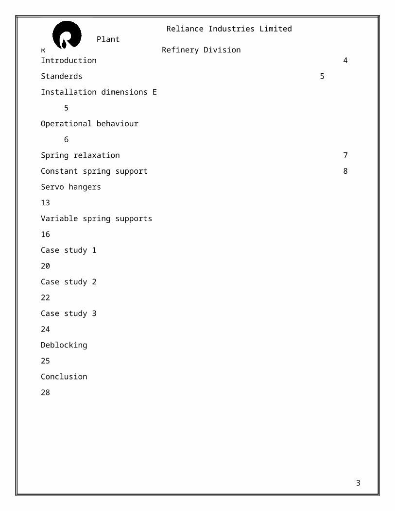
Introduction 4
Standerds 5
Installation dimensions E 5
Operational behaviour 6
Spring relaxation 7
Constant spring support 8
Servo hangers 13
Variable spring supports 16
Case study 1 20
Case study 2 22
Case study 3 24
Deblocking 25
Conclusion 28
2
Reliance Industries Limited Clean Fuels Plant R Refinery Division
ACKNOWLEDGEMENT
The fate of any Project is decided by the efforts put by every single person involved in the pursuance of
Project. Success can not be achieved single handedly. It is the team effort the sails the ship to the coast.
So, I would like express my deep gratitude towards everyone who helped me in completing the project. I
would like to thank my mentor Mr. Mahesh Davera (Manager – Mech.) and Mr.Rateesh Venugopalan
(Manager - Mech), for spending their valuable time in assessing my progress continuously, thereby guiding
me throughout the training period. I wish to warmly thank Mr.D.M.Rindani (HOD-Mechanical) for all the
halp he assured when needed.
I express my sincere thanks to Dr. B.P. Singh (SGM, PMDI) for their moral support in course of my
training. I also thank to all contract workers, Shift In charges and Operators who co-operate with me and
help me in all my needs. Finally, I would like to thank all my colleagues in the plant for sharing their
practical knowledge.
3
Reliance Industries Limited Clean Fuels Plant R Refinery Division
SPRING SUPPORTS – AN INTRODUCTION
DEFINATION
Standard supports are pipe support components, the construction of which, in form and dimension as well as in design data rating & capacity, i.e. certified and catalogued, and which are manufactured according to firmly established reproducible procedures
For the support of industrial piping systems, the use of standard support is regarded as well proven, up to date technology. Only a correspondingly high level of standardization in support components can adequately satisfy the justifiable demand of products that are technically top class and economically attractive at the same time the complex requirement of modern pipe supports are :
o Reliable functioningo Maintenance free operationo Low unit priceo Simple planning with dp systemso Instant availabilityo Economical installation strategyo Easy to installo Supplementary supply benefits
Standard supports must fulfill the following criteria:
o Component shapes are uniform and designed for optimum utilization of materialso Units are compatible regarding connecting dimensions and loading capacityo Units are catalogued and clearly identifiable by a designation systemo Components are manufactured in series productiono Component comply with relevant standards and international procedureso Functional capacity, suitability and durability of units are well proven
The nominal load is used for the determination of the different types of spring to be used. For the statically determined components the nominal load corresponds to the spring elements, such as spring hangers and constant hangers. The maximum permissible hot load lies considerably higher than the nominal load when components are used as rigid supports, and is tied to the load capacity of the connection threads.Spring and constant hangers in the blocked position also count as rigid supports, whereby for cold loads in hydrostatic tests (short duration) the emergency loads can be exploited.
4
Reliance Industries Limited Clean Fuels Plant R Refinery Division
STANDARDS
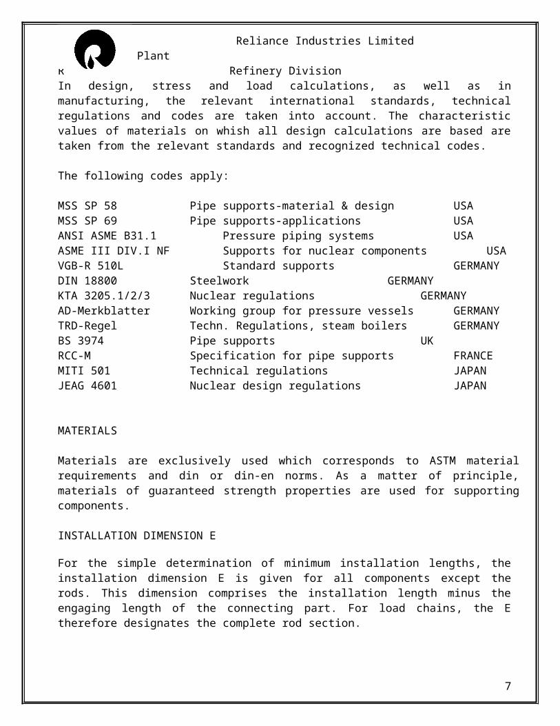
In design, stress and load calculations, as well as in manufacturing, the relevant international standards, technical regulations and codes are taken into account. The characteristic values of materials on whish all design calculations are based are taken from the relevant standards and recognized technical codes.
The following codes apply:
MSS SP 58 Pipe supports-material & design USAMSS SP 69 Pipe supports-applications USAANSI ASME B31.1 Pressure piping systems USAASME III DIV.I NF Supports for nuclear components USAVGB-R 510L Standard supports GERMANYDIN 18800 Steelwork GERMANYKTA 3205.1/2/3 Nuclear regulations GERMANYAD-Merkblatter Working group for pressure vessels GERMANYTRD-Regel Techn. Regulations, steam boilers GERMANYBS 3974 Pipe supports UKRCC-M Specification for pipe supports FRANCEMITI 501 Technical regulations JAPANJEAG 4601 Nuclear design regulations JAPAN
MATERIALS
Materials are exclusively used which corresponds to ASTM material requirements and din or din-en norms. As a matter of principle, materials of guaranteed strength properties are used for supporting components.
INSTALLATION DIMENSION E
For the simple determination of minimum installation lengths, the installation dimension E is given for all components except the rods. This dimension comprises the installation length minus the engaging length of the connecting part. For load chains, the E therefore designates the complete rod section.
To determine the total length of the rods in a load chain, all the E dimensions are to be added together. The sum of these is then to be compared with the total installation length. If the resulting difference is greater than the sum of the engagement depths (X dimensions), the chain selected is appropriate for the total installation height. For load chains consisting solely of pin connections, the minimum installation dimension follows from the sum of all E dimensions. For length adjustment in installation condition (adjustment of pipe installation position, actuation of loading), the lower connections in
5
Reliance Industries Limited Clean Fuels Plant R Refinery Division
constant and spring hangers provide a turnbuckle function. This way, subsequent adjustment of the installation lengths within a sufficient range is possible.
OPERATIONAL BEHAVIOR
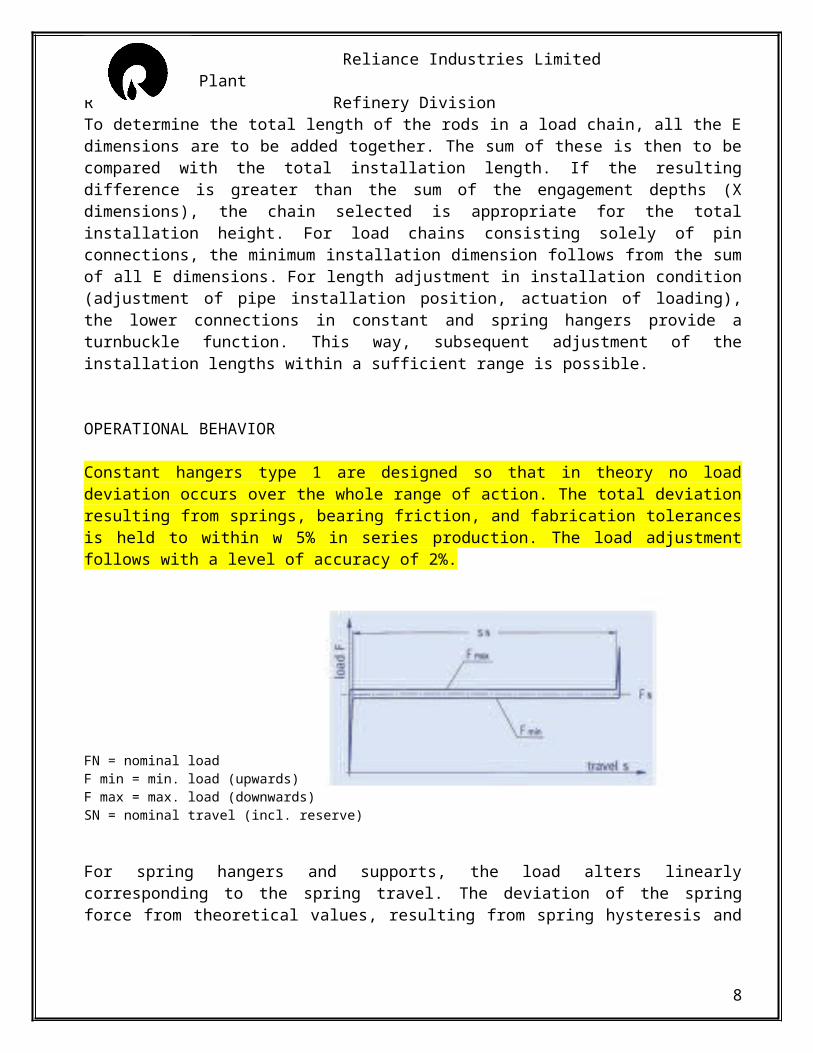
Constant hangers type 1 are designed so that in theory no load deviation occurs over the whole range of action. The total deviation resulting from springs, bearing friction, and fabrication tolerances is held to within w 5% in series production. The load adjustment follows with a level of accuracy of 2%.
FN = nominal loadF min = min. load (upwards)F max = max. load (downwards)SN = nominal travel (incl. reserve)
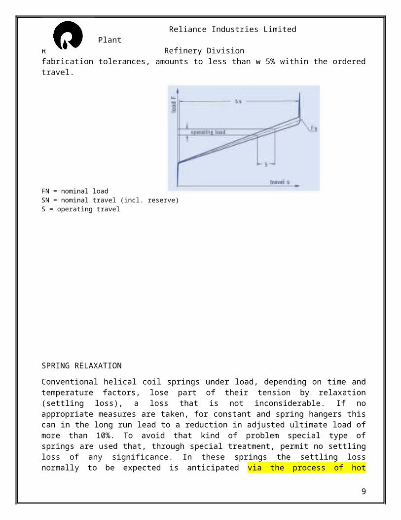
For spring hangers and supports, the load alters linearly corresponding to the spring travel. The deviation of the spring force from theoretical values, resulting from spring hysteresis and fabrication tolerances, amounts to less than w 5% within the ordered travel.
FN = nominal loadSN = nominal travel (incl. reserve)S = operating travel
6
Reliance Industries Limited Clean Fuels Plant R Refinery Division
SPRING RELAXATION
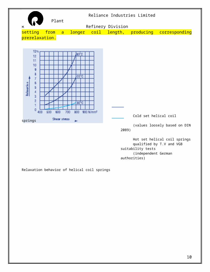
Conventional helical coil springs under load, depending on time and temperature factors, lose part of their tension by relaxation (settling loss), a loss that is not inconsiderable. If no appropriate measures are taken, for constant and spring hangers this can in the long run lead to a reduction in adjusted ultimate load of more than 10%. To avoid that kind of problem special type of springs are used that, through special treatment, permit no settling loss of any significance. In these springs the settling loss normally to be expected is anticipated via the process of hot setting from a longer coil length, producing corresponding prerelaxation.
Cold set helical coil springs(values loosely based on DIN 2089)
Hot set helical coil springsqualified by T.V and VGB suitability tests(independent German authorities)
Relaxation behavior of helical coil springs
7
Reliance Industries Limited Clean Fuels Plant R Refinery Division
CONSTANT SPRING SUPPORTS
To prevent detrimental constrains in the system, thermal expansion in piping and other plant components must not be hindered.To compensate for vertical movement caused by thermal expansion, constant hangers provide the right solution. Via constant hangers, the respective piping loads are constantly absorbed and transferred with no significant deviation over the whole range of movement.Significant load would act as harmful and uncontrolled extra loads in the system.In this case, connection points are especially at risk because of unacceptable forces and moments. It is vital that the constant hangers work reliably and efficiently. As this is decisive for the operational safety and long life of the piping system.
FUNCTIONAL PERFORMANCES
The specific functional principle of constant hangers guarantees absolute consistency across the entire travel range. This is not even affected by load adjustment. Only a minor friction force resulting from tolerances and bearings has to be taken into account as a slight deviation. The hysteresis produced by this is kept within very narrow limits. For normal load settings, the deviation in the operating load is around +3%. Using proper selection process, attaining a maximum deviation of +2% is possible.
Generally permissible deviations are laid down in the following international standards:
MSS-SP 58, USA, max. +6% referring to operating loadVGB R 510 L and KTA 3205.3, Germany, max +5% referring to operating loadEN Europa Nomenentwurf, max.+5%, referring to operating load. the mean load deviation is limited to max. +2%.
FUNCTION TEST
Before delivery of the springs to the client, all spring hangers are tested for correct function and set to the required load. The test results are graphically and digitally plotted and are supplied to the clients if required. The load settings are stamped on riveted aluminum name plate. In addition, the set load is permanently marked on the load scale. Cold and hot positions are marked on the travel scale in white
8
Reliance Industries Limited Clean Fuels Plant R Refinery Division
and red respectively. The relevant travel position is directly readable on the travel scale in mm or inch. The set load can be read from the load scale in KN.
LOAD ANALYSIS
Strict demands are placed on constant hangers to ensure reliable functions:o Absolute consistency for all load settingso Minimum mechanical friction
Likewise, particular requirements are to be fulfilled for the continuous monitoring of the piping system performance.
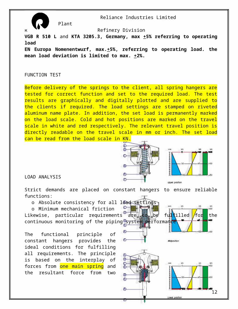
The functional principle of constant hangers provides the ideal conditions for fulfilling all requirements. The principle is based on the interplay of forces from one main spring and the resultant force from two hooked up compensating springs. The directions of force of the two pre-stressed compensating springs are opposed to each other in the form of a parallelogram of forces.
The suspended load F acts directly on the main spring B via the central load tube A. the force of the compensating springs C operates as resultant force F2, via cams D and rollers E. the forces acts additionally on the load tube. The main spring force F1 and resultant force F2 when the load is moved over the travel range S. this is in accordance with the characteristics of the spring, and the angle and shape of the cams. The individual components are arranged in such a way that any change in the resultant spring constancy correspond exactly with the characteristic curve of the main spring. In this way the force on the main spring is evenly compensated for, providing constant supporting force.
Down towards the apex of the cams the resultant force diminishes in proportion to the increase of the relatively low starting force of the main spring. At the apex of the cams the forces of the compensating springs are cancelled out. The resultant is zero. At this point only the main spring
9
Reliance Industries Limited Clean Fuels Plant R Refinery Division
carries the load. beyond the apex, the direction of the proportionality increasing resultant force of the compensating springs is reversed. It now reduces the relatively strong main spring force in the same way.
The sum of, or the difference between the forces F1 and F2 at each point in the travel range is equal to F.
LOAD ADJUSTMENT
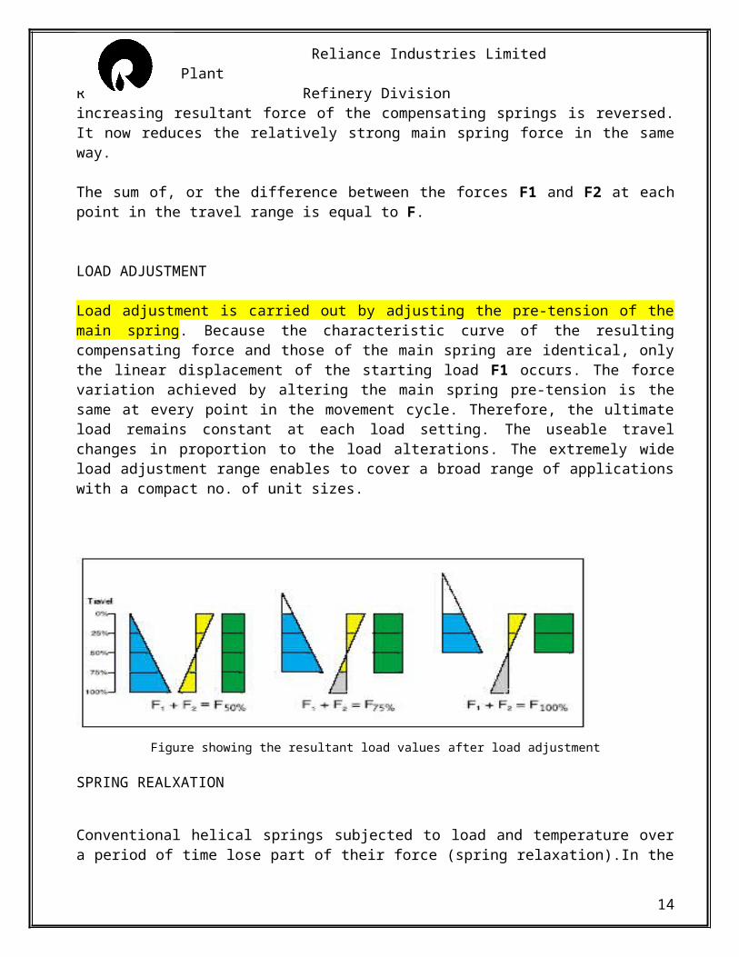
Load adjustment is carried out by adjusting the pre-tension of the main spring. Because the characteristic curve of the resulting compensating force and those of the main spring are identical, only the linear displacement of the starting load F1 occurs. The force variation achieved by altering the main spring pre-tension is the same at every point in the movement cycle. Therefore, the ultimate load remains constant at each load setting. The useable travel changes in proportion to the load alterations. The extremely wide load adjustment range enables to cover a broad range of applications with a compact no. of unit sizes.
Figure showing the resultant load values after load adjustment
SPRING REALXATION
Conventional helical springs subjected to load and temperature over a period of time lose part of their force (spring relaxation).In the long term, it can cause a reduction in the adjusted support loads of more than 10% in constant and variable spring supports. Use of prerelaxed springs which by an artificial aging process allow no significant settling loss. In a hot setting procedure with extended coil lengths a corresponding pre-plastification is attained. The settling loss normally to be expected is thereby prevented.
CORROSION PROTECTION
10
Reliance Industries Limited Clean Fuels Plant R Refinery Division
Constant hangers are finished with standard coating system which in conjunction with a metallically pure treated surface offers superior corrosion protection with high mechanical stability. Bearings and pins are made from stainless steel. All threaded parts and cams are electrogalvanized and yellow chromatized. The spring coil surfaces are given special finishing treatment. The standard corrosion protection for constant hangers needs no maintenance inside buildings, or in areas protected from the weather. For components in the open and in special cases of operation, a more comprehensive corrosion protection can be agreed on.
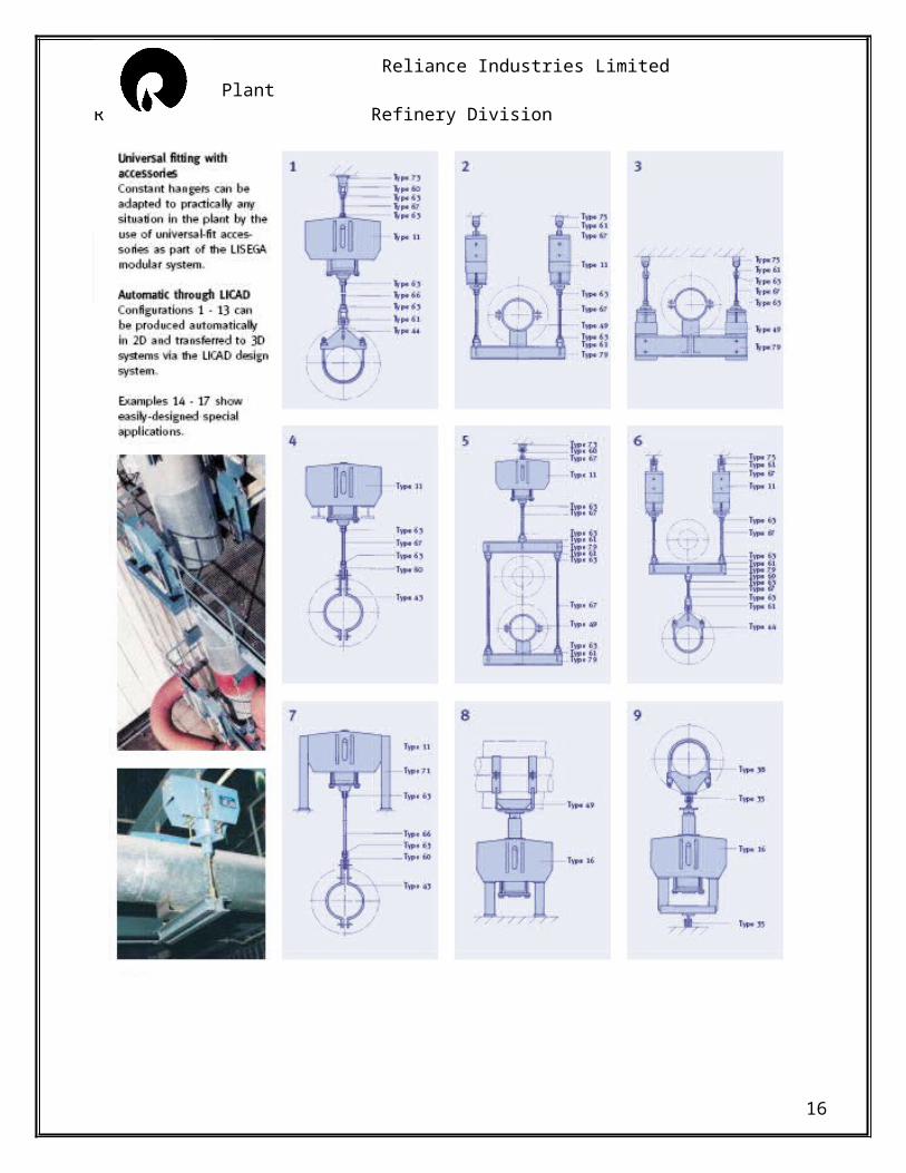
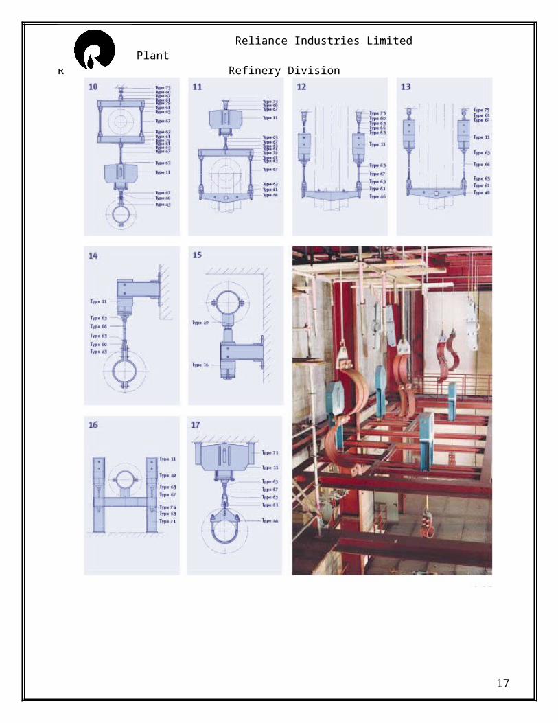
INSTALLATION EXAMPLES
11
Reliance Industries Limited Clean Fuels Plant R Refinery Division
12
Reliance Industries Limited Clean Fuels Plant R Refinery Division
13
Reliance Industries Limited Clean Fuels Plant R Refinery Division
SERVO HANGERS
Despite the use of variable spring and constant hangers, piping systems and other components are, under certain conditions, obstructed in their thermal movement by friction or other influences. In such cases servo hangers can be usefully employed.
Applications
In the ideal situation the weight of the piping is almost balanced out with the set load of the constant hangers. The sum of deviations present and the additional stresses in the piping system thereby caused then remain within the permissible harmless range. In certain cases, total deviation can exceed permissible levels. In the form of secondary stresses it can considerably reduce the life span of the piping or its connections in the area of creep strength depending on time.
Deviations can occur due to:o wall thickness tolerances of the pipes, if these are not weighed individually and weight
differences are not taken into considerationo insulation weights not exactly determinable in advanceo mechanical friction and manufacturing tolerances within constant hangers (permissible _ 5%)o relaxed springs in constant hangerso unpredictable random influences on pipe staticso differences between theoretical and actual values of load distribution
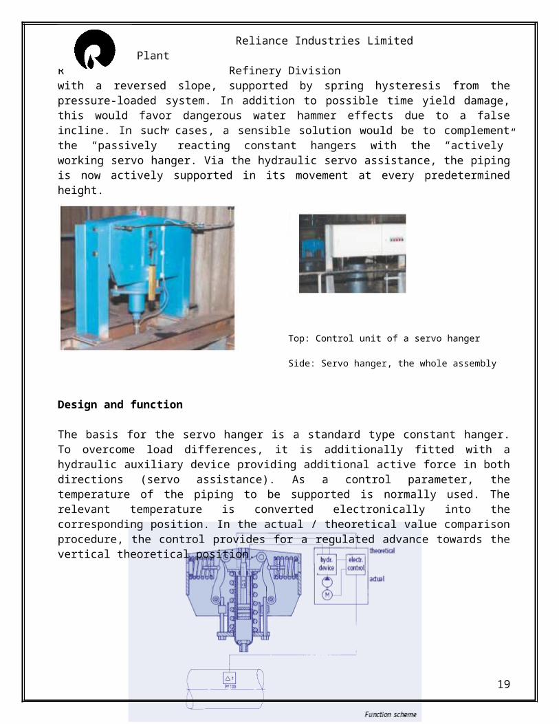
A combination of deviations can normally be expected, which cumulatively can amount to considerably high values. This is especially unfavorable with long-legged (soft) piping systems. Vertical movements can be obstructed here, even on relatively minor individual deviations, and partially or even totally suppressed. Apart from the extra load caused, unacceptable sagging can occur with a reversed slope, supported by spring hysteresis from the pressure-loaded system. In addition to possible time yield damage, this would favor dangerous water hammer effects due to a false incline. In such cases, a sensible solution would be to complement the “passively” reacting constant hangers with the “actively” working servo hanger. Via the hydraulic servo assistance, the piping is now actively supported in its movement at every predetermined height.
Top: Control unit of a servo hanger
Side: Servo hanger, the whole assembly
14
Reliance Industries Limited Clean Fuels Plant R Refinery Division
Design and function
The basis for the servo hanger is a standard type constant hanger. To overcome load differences, it is additionally fitted with a hydraulic auxiliary device providing additional active force in both directions (servo assistance). As a control parameter, the temperature of the piping to be supported is normally used. The relevant temperature is converted electronically into the corresponding position. In the actual / theoretical value comparison procedure, the control provides for a regulated advance towards the vertical theoretical position.
Electro-hydraulic control
The hydraulic unit and the electronic control are housed separately from each other in a switchgear cabinet mounted near the servo hanger (max distance 16m). The hydraulic piston controlling the movement is located in the load tube of the constant hanger.
Automatic safety switch
The electrohydraulic control is designed in such a way that only the servo assistance is lost if there is an operational breakdown, e.g. a power failure. The unit itself would carry on operating in the normal way as a constant hanger. For deviations in theoretical (temp.) / actual (travel) a tolerance range can be adjusted. The control shuts off automatically if the deviation lies outside these values.
Manual shut off
For possible maintenance work in the system or at the boiler, the servo assistance can be shut on or off by hand.
15
Reliance Industries Limited Clean Fuels Plant R Refinery Division
LOAD DISTRIBUTION B (SPRING DEGAGGING)
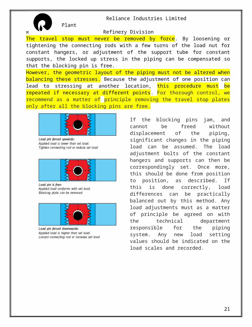
The travel stop must never be removed by force. By loosening or tightening the connecting rods with a few turns of the load nut for constant hangers, or adjustment of the support tube for constant supports, the locked up stress in the piping can be compensated so that the blocking pin is free.However, the geometric layout of the piping must not be altered when balancing these stresses. Because the adjustment of one position can lead to stressing at another location, this procedure must be repeated if necessary at different points. For thorough control, we recommend as a matter of principle removing the travel stop plates only after all the blocking pins are free.
If the blocking pins jam, and cannot be freed without displacement of the piping, significant changes in the piping load can be assumed. The load adjustment bolts of the constant hangers and supports can then be correspondingly set. Once more, this should be done from position to position, as described. If this is done correctly, load differences can be practically balanced out by this method. Any load adjustments must as a matter of principle be agreed on with the technical department responsible for the piping system. Any new load setting values should be indicated on the load scales and recorded.
16
Reliance Industries Limited Clean Fuels Plant R Refinery Division
VARIABLE SPRING SUPORT
To prevent constraints in the system, thermal expansion in the piping and other piping components must not be hindered. The piping must therefore be supported in a correspondingly elastic manner.
Spring elements
To compensate for slight vertical displacements in the piping, spring components are used as supports. The functioning of these components is based on preset helical coil springs which exert a variable supporting load over the whole range of movement corresponding to the given spring characteristics. Load variations resulting from this are limited through corresponding specifications based on stress calculations for the piping -this depends on the sensitivity of the system.
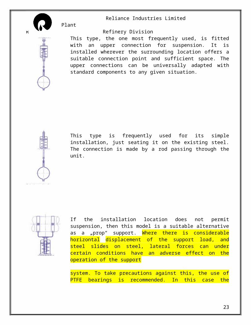
This type, the one most frequently used, is fitted with an upper connection for suspension. It is installed wherever the surrounding location offers a suitable connection point and sufficient space. The upper connections can be universally adapted with standard components to any given situation.
This type is frequently used for its simple installation, just seating it on the existing steel. The connection is made by a rod passing through the unit.
If the installation location does not permit suspension, then this model is a suitable alternative as a „prop“ support. Where there is considerable horizontal displacement of the support load, and steel slides on steel, lateral forces can under certain conditions have an adverse effect on the operation of the support
17
Reliance Industries Limited Clean Fuels Plant R Refinery Division
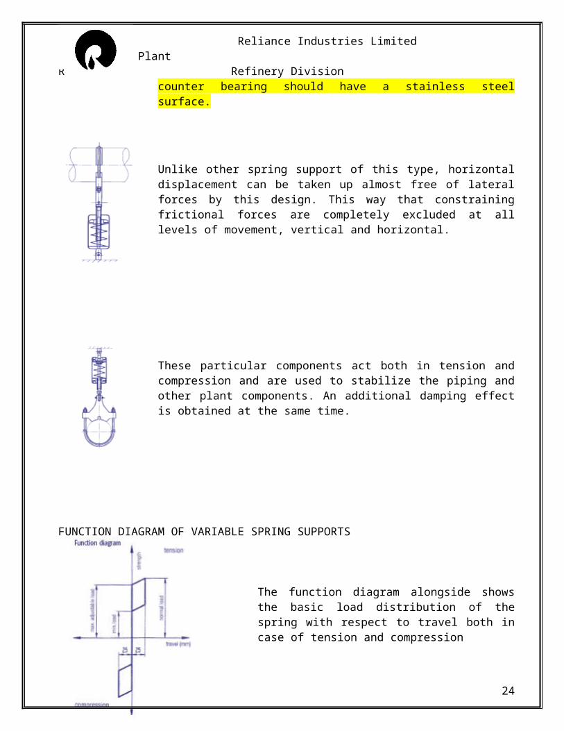
system. To take precautions against this, the use of PTFE bearings is recommended. In this case the counter bearing should have a stainless steel surface.
Unlike other spring support of this type, horizontal displacement can be taken up almost free of lateral forces by this design. This way that constraining frictional forces are completely excluded at all levels of movement, vertical and horizontal.
These particular components act both in tension and compression and are used to stabilize the piping and other plant components. An additional damping effect is obtained at the same time.
FUNCTION DIAGRAM OF VARIABLE SPRING SUPPORTS
The function diagram alongside shows the basic load distribution of the spring with respect to travel both in case of tension and compression
18
Reliance Industries Limited Clean Fuels Plant R Refinery Division
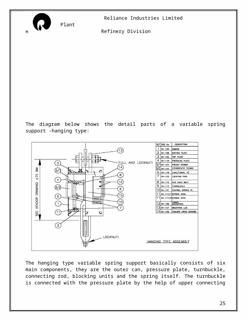
The diagram below shows the detail parts of a variable spring support -hanging type:
The hanging type variable spring support basically consists of six main components, they are the outer can, pressure plate, turnbuckle, connecting rod, blocking units and the spring itself. The turnbuckle is connected with the pressure plate by the help of upper connecting rod through the spring. The lower connecting rod connects the turnbuckle with the line. As the line comes under load, the load is transferred to the spring through the connecting rod, turnbuckle and the pressure plate. The pressure plate compresses the spring which gets nullified by the spring force and thus the line stays in its position
19
Reliance Industries Limited Clean Fuels Plant R Refinery Division
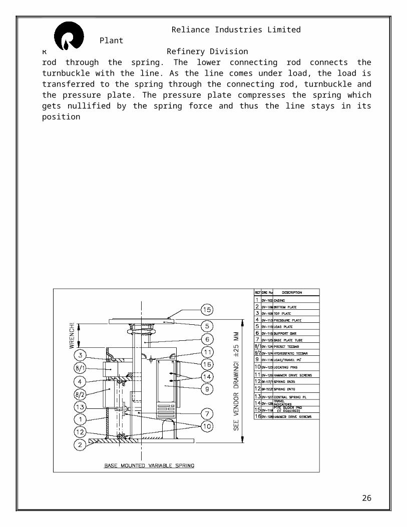
The base mounted variable type of spring support basically consists of five main parts, they are the load tube, pressure plate, base plate tube or the guide, the blocking units and the spring itself. The pressure plate and the load tube are internally and externally threaded simultaneously and are fixed with one another. As the load of the line falls upon the top plate, it gradually transfers the load to the pressure plate via the load tube. The pressure plate in return compresses the spring which actually nullifies the load and holds the line in position.
LOAD READJUSTMENT
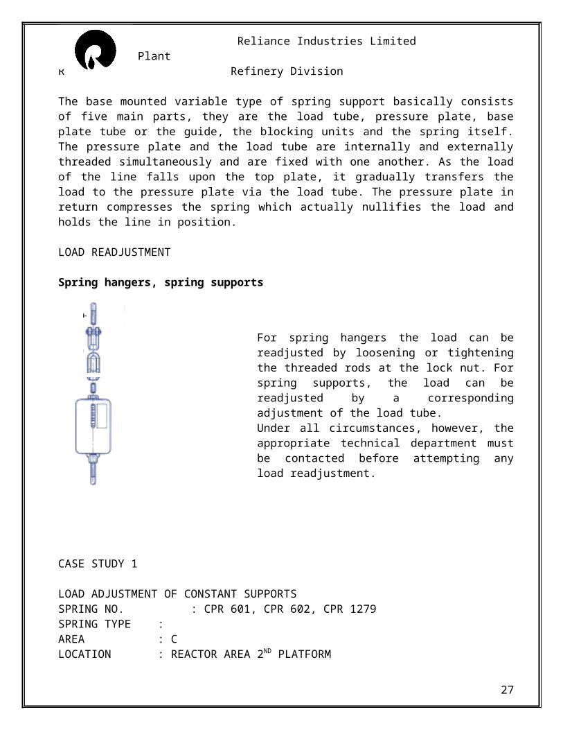
Spring hangers, spring supports
For spring hangers the load can be readjusted by loosening or tightening the threaded rods at the lock nut. For spring supports, the load can be readjusted by a corresponding adjustment of the load tube. Under all circumstances, however, the appropriate technical department must be contacted before attempting any load readjustment.
20
Reliance Industries Limited Clean Fuels Plant R Refinery Division
CASE STUDY 1
LOAD ADJUSTMENT OF CONSTANT SUPPORTSSPRING NO. : CPR 601, CPR 602, CPR 1279SPRING TYPE :AREA : CLOCATION : REACTOR AREA 2ND PLATFORM
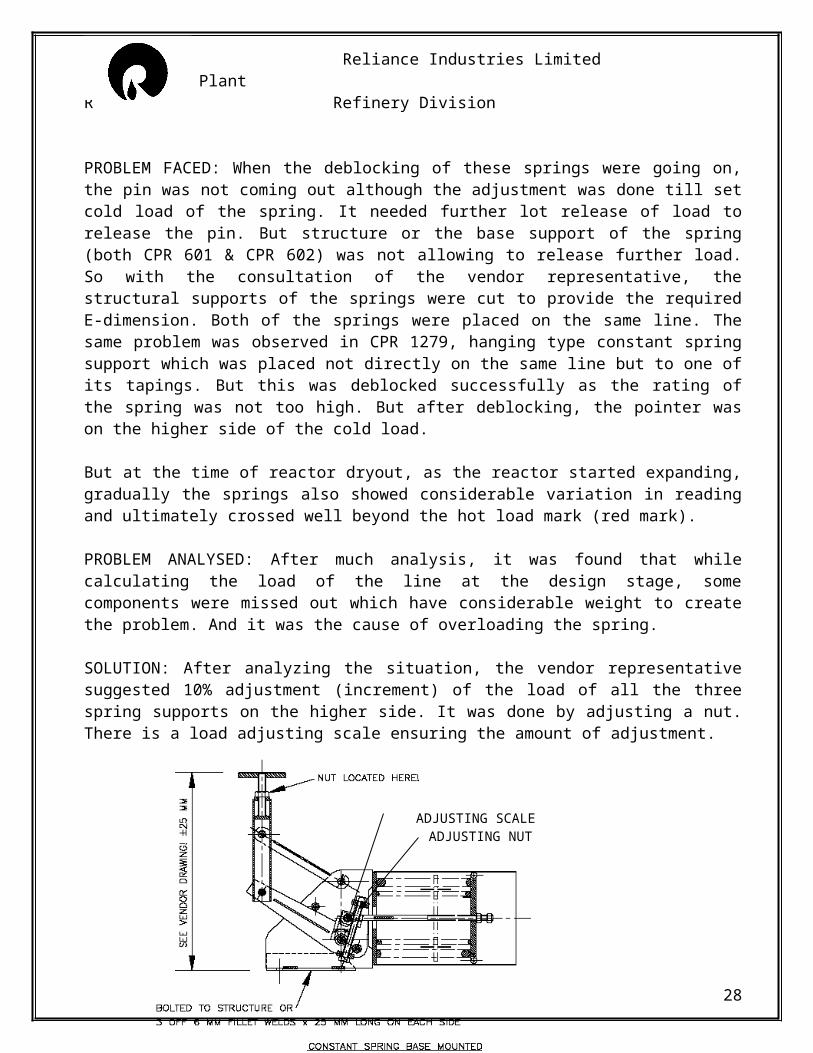
PROBLEM FACED: When the deblocking of these springs were going on, the pin was not coming out although the adjustment was done till set cold load of the spring. It needed further lot release of load to release the pin. But structure or the base support of the spring (both CPR 601 & CPR 602) was not allowing to release further load. So with the consultation of the vendor representative, the structural supports of the springs were cut to provide the required E-dimension. Both of the springs were placed on the same line. The same problem was observed in CPR 1279, hanging type constant spring support which was placed not directly on the same line but to one of its tapings. But this was deblocked successfully as the rating of the spring was not too high. But after deblocking, the pointer was on the higher side of the cold load.
But at the time of reactor dryout, as the reactor started expanding, gradually the springs also showed considerable variation in reading and ultimately crossed well beyond the hot load mark (red mark).
PROBLEM ANALYSED: After much analysis, it was found that while calculating the load of the line at the design stage, some components were missed out which have considerable weight to create the problem. And it was the cause of overloading the spring.
SOLUTION: After analyzing the situation, the vendor representative suggested 10% adjustment (increment) of the load of all the three spring supports on the higher side. It was done by adjusting a nut. There is a load adjusting scale ensuring the amount of adjustment.
ADJUSTING SCALE ADJUSTING NUT
21
Reliance Industries Limited Clean Fuels Plant R Refinery Division
22
Reliance Industries Limited Clean Fuels Plant R Refinery Division
CASE STUDY 2
STRUCTURE MODIFICATION FOR VARIABLE SPRING SUPPORTSPRING NO. : SPR 1275SPRING TYPE : HANGING TYPEAREA : CLOCATION : REGENERATOR AREA 3RD PLATFORM
PROBLEM FACED: At the time of deblocking, the spring was not in load, so the turnbuckle was tightened to get it deblocked. But after much effort, the spring was not deblocked. It was noticed that the structural support, which was cantilever in type, is bending down.
PROBLEM ANALYSED: After consultation with concerned departments, it was found that the bracing on the cantilever was missing and that had actually led to the problem.
SOLUTION: The cantilever beam was provided an additional support from the top beam to hold it in its position and stop it from bending.
A- The structure after being sagged by the weight of the spring.;B- The existing column through the support is taken
23
A B
Reliance Industries Limited Clean Fuels Plant R Refinery Division
24
Reliance Industries Limited Clean Fuels Plant R Refinery Division
CASE STUDY 3
STRUCTURE MODIFICATION FOR VARIABLE SPRING SUPPORTSPRING NO. : SPR 117SPRING TYPE : HANGING TYPEAREA : FLOCATION : AT THE JUNCTION OF E RACK AND F AREA
PROBLEM FACED: While deblocking the spring SPR-117, it was found that the E-dimension i.e. the gap between the spring and the pipe is insufficient to adjust the turnbuckle and deblock the spring. There was no scope to shorten the connecting rod as that was also shortened to its shortest limit. Another 100mm to 150mm was needed to deblock the spring properly.
PROBLEM ANALYSED: After much analysis it was concluded that the only way left was to move the support through which the spring was hanging a little bit up according to the requirement. But the spring was hanging from a CPS and the bottom part of the CPS was supporting another 16” line.
SOLUTION: It was discussed with the design department and proposed that 200mm of the top beam of the CPS would be cut and another beam to be welded on the top of it to compensate the space required for deblocking without weakening the strength of the CPS for supporting other pipes.
The portion of the CPS that was added over the existing one after cutting it
Existing CPS
Spring position is elvated
25
Reliance Industries Limited Clean Fuels Plant R Refinery Division
DEBLOCKING
Deblocking or degagging is very essential operation with respect to proper working of a spring support. At first a line is erected considering various supports and essential equipments as given in the isometric drawing. If there is a spring support, the line is generally hold with temporary supports during the erection time. After complete erection the spring is set up at the required position. If the spring is not block then due to the load of the line the spring will allow the line to go down until the load is balanced by the spring force.To avoid this the springs are pre tensioned to the required value from the manufacturing site only. And to hold the spring at that value metallic blocks or gags are used. When the total boxup of the line is done, they should theoretically become free and be moved. However practically many a times this does not occur and minor adjustments are needed to make the gags free. The systematic approach to this adjustment pertaining to the removing of the blocks is called deblocking or deggagging.
DEBLOCKING PROCEDURE FOR CONSTANT AND SPRING HANGERS
The prerequisite for the deblocking of constant and spring hangers is that the supported components such as piping, reactors or containers, are fully installed and that the total weight is brought to bear, i.e.
o All connections must be completedo The insulation must be fully fittedo The piping, equipments, must be completely filled with a weight relevant medium
The geometry of the piping must not be altered when deblocking. It must be carried out line by line, betweenbetween fixed points or connections. Possible load differences between theoretical and actual must load be discerned.The action taken is to be documented as follows:
1. Record hanger data from nameplate
2. Determine height measurement of piping by measuring between building structure and piping. The measurement is to be documented on the list under the column “length structure-pipe
Examples for determining the length structure-pipe is given below
26
Reliance Industries Limited Clean Fuels Plant R Refinery Division
3. The deblocking operation begins at the least rigid point of the piping (frequently in the middle). The operation takes place in both directions alternately. First of all the tie rods, adjusting nuts, adjusting spindles or turnbuckles are turned, until the blocking pieces are free or the piping tends to lift or sink. The direction of turning is determined by the set up of the blocking pieces. The maximum thread engagement depths are to be inspected
4. The blocking pieces may only be removed when the procedure under point 3 has been carried out with all hangers supporting a line.
27
Reliance Industries Limited Clean Fuels Plant R Refinery Division
5. If all the blocking pieces for a line are free, they may be removed. If any blocking pieces are still binding, then the point three procedure is to be repeated, possibly several times.
6. If after this the blocking pieces still cannot be removed, then the load correction procedure is to be carried out after discussion with the respective technical department. This must be documented on the list.
7. The blocking pieces are to be stored safely in accordance with instructions.
8. When all the blocking pieces are removed, the following must be recorded on the list:
- blocking position (cold load)- travel position after deblocking- length structure-pipe after deblocking
SOME GENERAL MISTAKES DURING DEBLOCKING
During audits carried out after deblocking, there are some common points that comes out whish seems to be very trivial but holds potential to hinder the proper working of the spring supports and hence the line that is supported. To avoid these there are some simple points that is to be kept in notice at the time of deblocking.
o Ensure the locknuts are tightened after deblocking.o The split pins are properly opened.o The pressure plate should not be nearly but always be exactly at the cold load position.o There should be adequate thread of the connecting rod inside the clevis and the turnbuckle.o The can should be tack welded to the base or bolted properly whichever applicable.o In case of trapeze type supports, trapeze stops are must.
28
Reliance Industries Limited Clean Fuels Plant R Refinery Division
CONCLUSION
In the concluding part of the project, it is again to be said that spring supports encompasses a wide range of solutions ahead of rigid type of supports where vibration and considerable expansion of line comes into play. During the tenure of two months of deputation to FCCU, where I was associated with springs only, I have experienced the working and contents of various kinds of springs. Spring supports of same ratings can be of various types not only with respect to hanging or pedestrial type but also with specific positioning of the springs. There were some spring supports which had considerable amount of travel range with respect to the spring support of the same class. We were in the degagging group and during the tenure of degagging 689 spring supports only of piping, we came across unique problems and mostly the solutions were brought up by us. In some cases by the design department. The problems are generally regarding the position if the spring supports as the are situated at the farthest extents of the plant. Some common mistakes associated with the spring supports are to be taken care of like tightening of locknuts and opening of the split pins. If they have to be re attended then all the arrangements starting from scaffolding building to manpower everything is required for such a trivial thing. During this tenure, I got the rare opportunity of load setting of constant springs. This is generally not required as the spring support already has considerable travel range. There were spring supports situated at such positions that we had to reach there by man lifting platforms with the help of crane.
Before concluding I would again like to thank all my colleagues and my seniors for extending their help at each step and every time I faced a problem.
29