Embed Size (px)
Citation preview
Berkeley Education Alliance for Research in Singapore
SinBerBEST Singapore-Berkeley Building Efficiency
and Sustainability in the Tropics
January 10, 2013
Anidolic Daylight Concentrator of Structural
Translucent Concrete Envelope
B. Huang
K.M. Mosalam and S.P. Chiew
2 SinBerBEST
Outline
1. Translucent Concrete (TC) Panel Prototype Production
2. Light Transmission Tests of the TC Panel
3. Light Transmission Simulation of the Optical Fiber (OF)
4. Light Concentration Analysis
5. Light Transmission Modeling of TC Panel
6. Conclusions and Future Goals
3 SinBerBEST
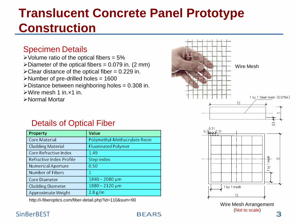
Translucent Concrete Panel Prototype
Construction
Wire Mesh
Wire Mesh Arrangement (Not to scale)
Details of Optical Fiber
http://i-fiberoptics.com/fiber-detail.php?id=110&sum=90
Specimen Details Volume ratio of the optical fibers = 5%
Diameter of the optical fibers = 0.079 in. (2 mm)
Clear distance of the optical fiber = 0.229 in.
Number of pre-drilled holes = 1600
Distance between neighboring holes = 0.308 in.
Wire mesh 1 in.×1 in.
Normal Mortar
4 SinBerBEST
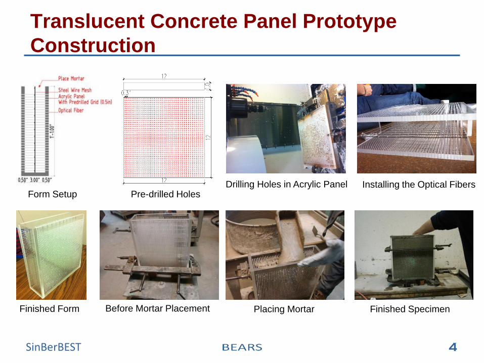
Translucent Concrete Panel Prototype
Construction
Installing the Optical Fibers
Before Mortar Placement Placing Mortar Finished Specimen
Form Setup
Finished Form
Pre-drilled Holes Drilling Holes in Acrylic Panel
5 SinBerBEST
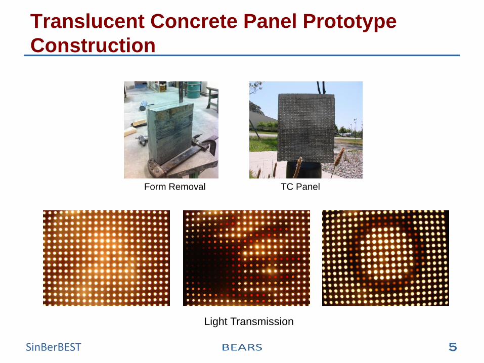
Translucent Concrete Panel Prototype
Construction
Form Removal TC Panel
Light Transmission
6 SinBerBEST
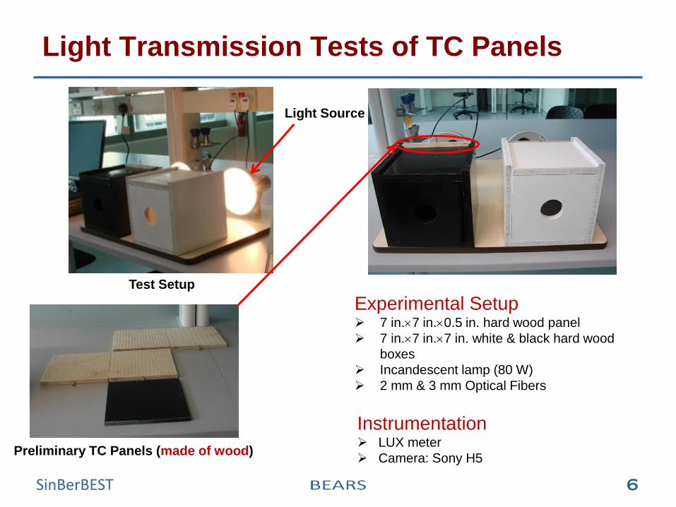
Light Transmission Tests of TC Panels
Light Source
Test Setup
Preliminary TC Panels (made of wood)
Experimental Setup 7 in.7 in.0.5 in. hard wood panel
7 in.7 in.7 in. white & black hard wood
boxes
Incandescent lamp (80 W)
2 mm & 3 mm Optical Fibers
Instrumentation LUX meter
Camera: Sony H5
7 SinBerBEST
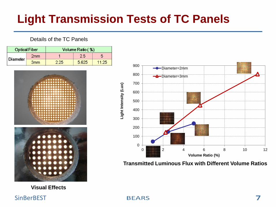
Light Transmission Tests of TC Panels
Visual Effects
Details of the TC Panels
0
100
200
300
400
500
600
700
800
900
0 2 4 6 8 10 12
Lig
ht
Inte
nsit
y (
Lu
x)
Volume Ratio (%)
Diameter=2mm
Diameter=3mm
Transmitted Luminous Flux with Different Volume Ratios
8 SinBerBEST
Light Transmission Simulation of the OF
Light Transmission Mechanism
Daylight Properties
Light Transmission Simulation of Straight OF
Bending Effect Simulation of the OF
9 SinBerBEST
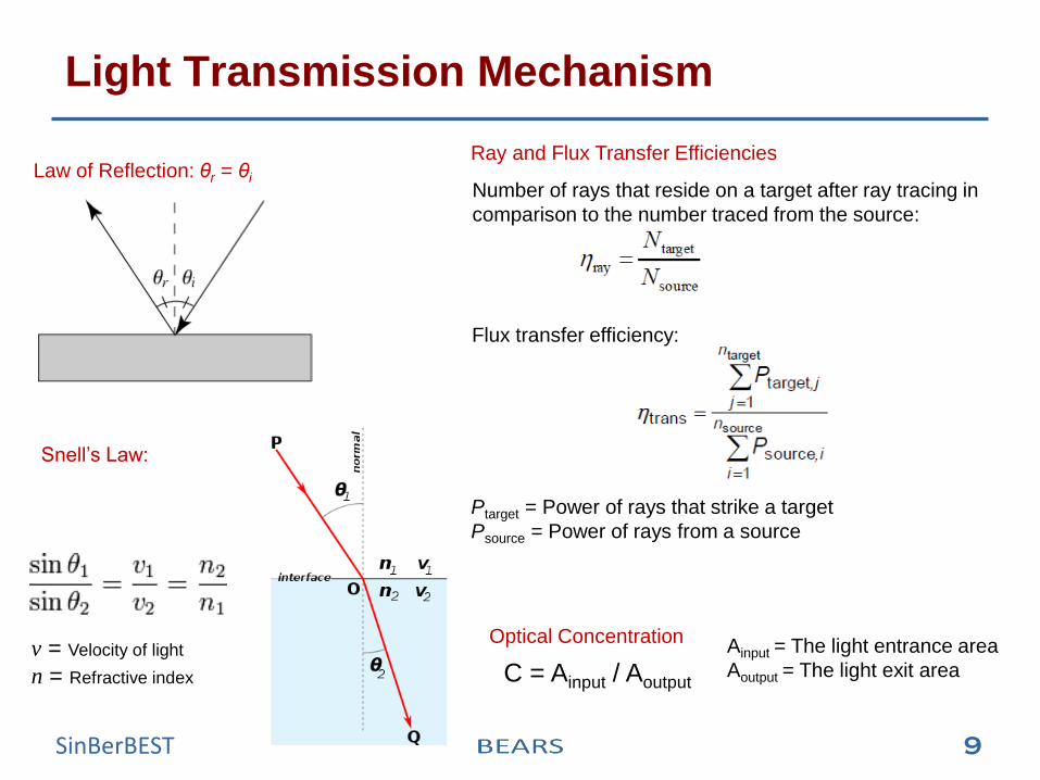
Light Transmission Mechanism
Law of Reflection: θr = θi
Snell’s Law:
v = Velocity of light
n = Refractive index
Ray and Flux Transfer Efficiencies
Number of rays that reside on a target after ray tracing in
comparison to the number traced from the source:
Flux transfer efficiency:
Ptarget = Power of rays that strike a target
Psource = Power of rays from a source
Optical Concentration
C = Ainput / Aoutput Ainput = The light entrance area
Aoutput = The light exit area
10 SinBerBEST
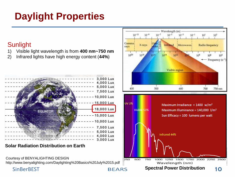
Daylight Properties
Sunlight 1) Visible light wavelength is from 400 nm~750 nm
2) Infrared lights have high energy content (44%)
Spectral Power Distribution
Courtesy of BENYALIGHTING DESIGN
http://www.benyalighting.com/Daylighting%20Basics%20July%2015.pdf
Solar Radiation Distribution on Earth
11 SinBerBEST
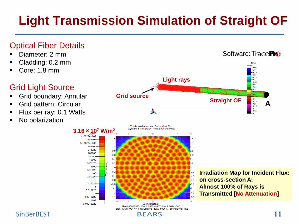
Light Transmission Simulation of Straight OF
Optical Fiber Details Diameter: 2 mm
Cladding: 0.2 mm
Core: 1.8 mm
Grid Light Source Grid boundary: Annular
Grid pattern: Circular
Flux per ray: 0.1 Watts
No polarization
3.16×10⁷ W/m2
Irradiation Map for Incident Flux:
on cross-section A:
Almost 100% of Rays is
Transmitted [No Attenuation]
Software:
Light rays
Straight OF Grid source
A
12 SinBerBEST
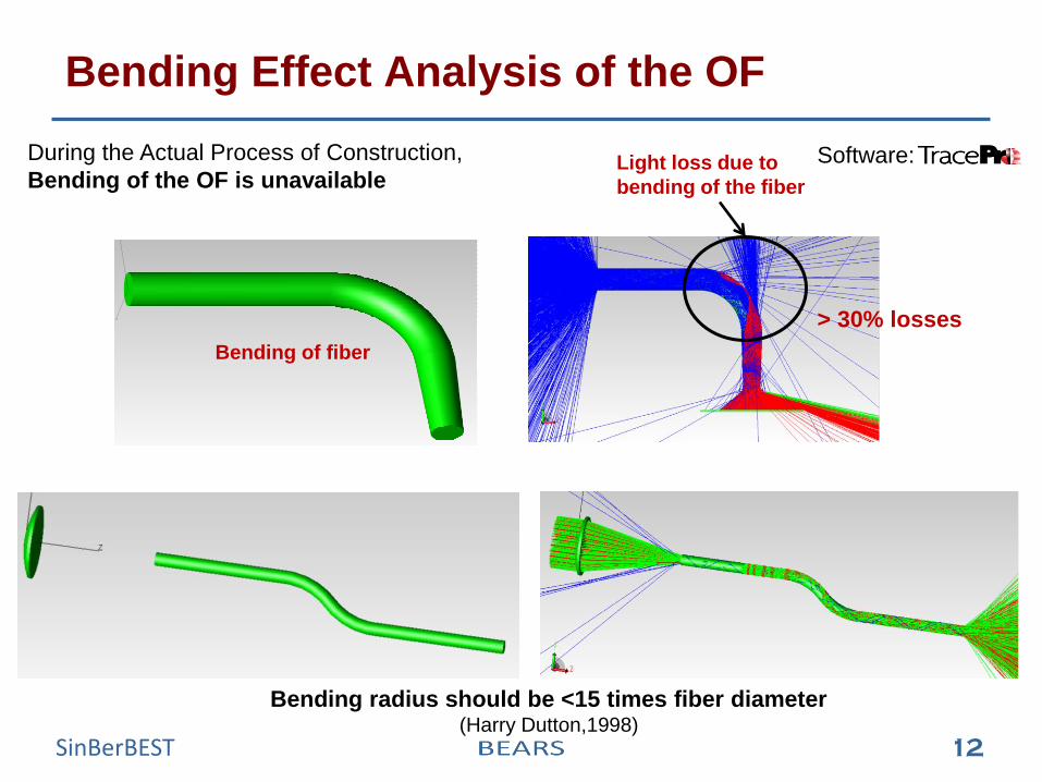
Bending Effect Analysis of the OF
During the Actual Process of Construction,
Bending of the OF is unavailable
Bending radius should be <15 times fiber diameter (Harry Dutton,1998)
Light loss due to
bending of the fiber
X
Y
Bending of fiber
> 30% losses
Software:
13 SinBerBEST
Light Concentration Analysis
Convex Lens
Compound Parabolic Concentrator (CPC)
14 SinBerBEST
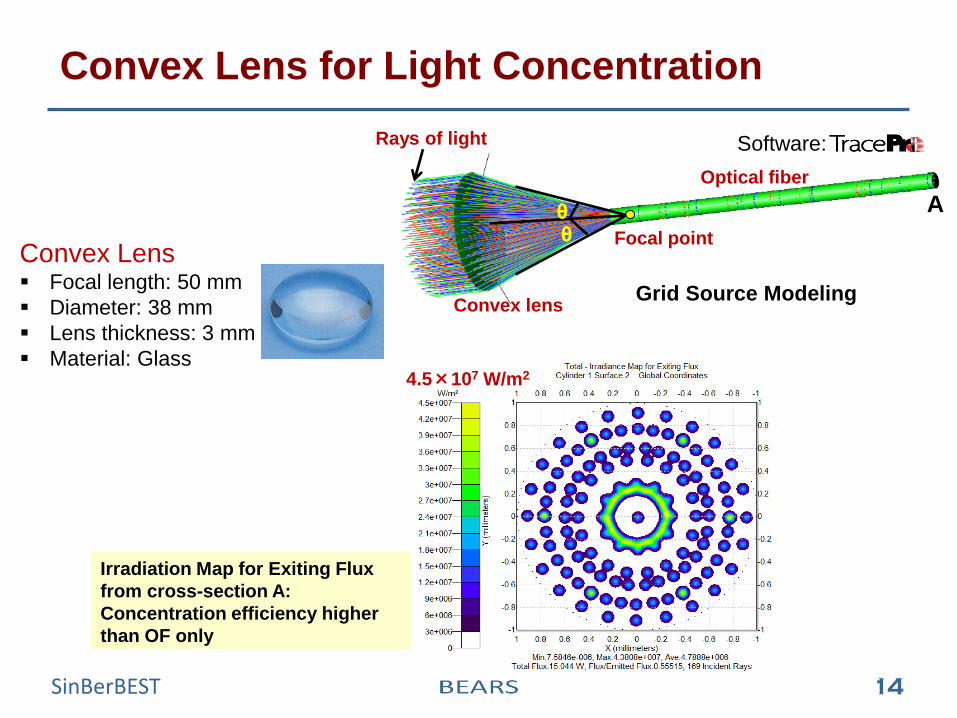
Convex Lens for Light Concentration
Convex Lens Focal length: 50 mm
Diameter: 38 mm
Lens thickness: 3 mm
Material: Glass 4.5×10⁷ W/m2
Irradiation Map for Exiting Flux
from cross-section A:
Concentration efficiency higher
than OF only
Grid Source Modeling
Rays of light
Convex lens
Optical fiber
θ θ Focal point
Software:
A
15 SinBerBEST
r
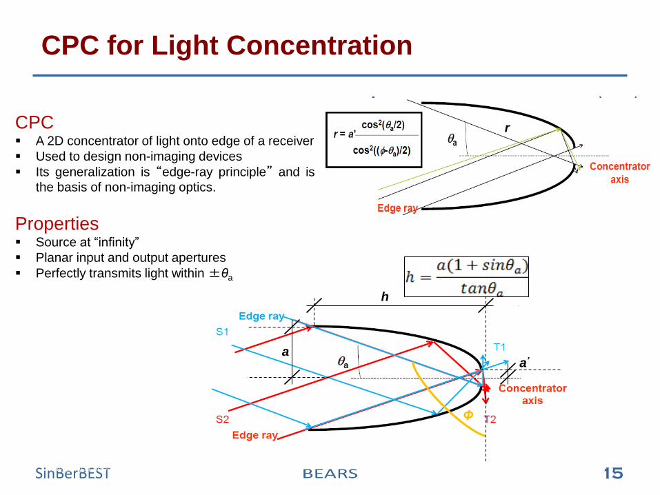
CPC for Light Concentration
Academy of Sciences San Francisco – Roof Level - (Architect: Renzo Piano)
CPC A 2D concentrator of light onto edge of a receiver
Used to design non-imaging devices
Its generalization is “edge-ray principle” and is
the basis of non-imaging optics.
Properties Source at “infinity”
Planar input and output apertures
Perfectly transmits light within ±θa
h
a a’
Φ
16 SinBerBEST
CPC for Light Concentration
X
Y
1 ecruoS dirG
²m/W1
59.0
9.0
58.0
8.0
57.0
7.0
56.0
6.0
55.0
5.0
54.0
4.0
53.0
3.0
52.0
2.0
51.0
1.0
50.0
0
CPC
Optical fiber
Light rays
Grid Source Modeling
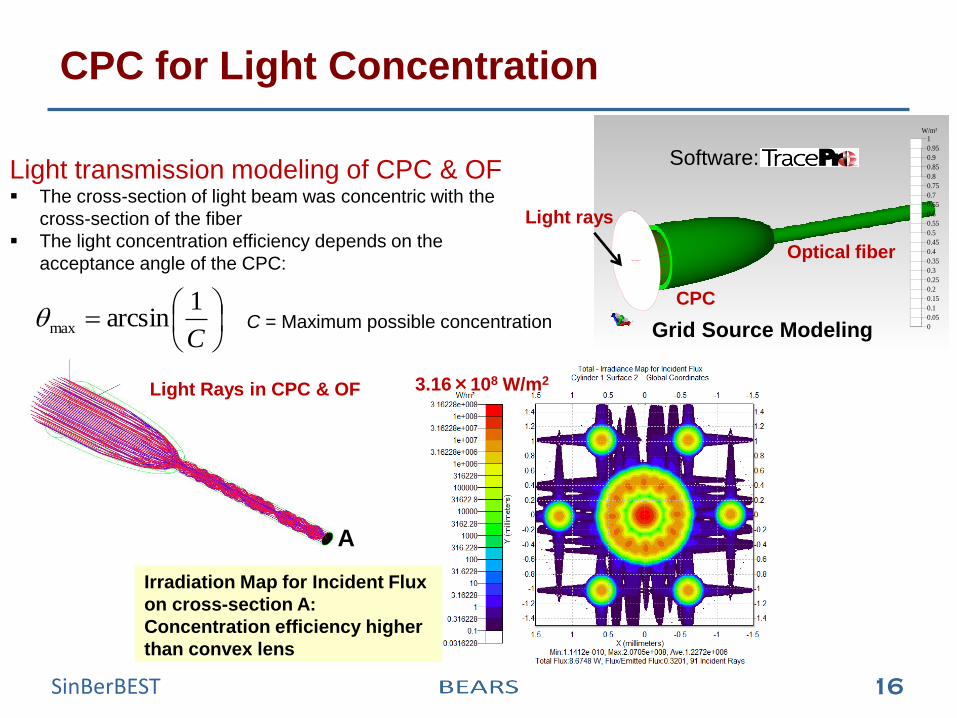
Software: Light transmission modeling of CPC & OF The cross-section of light beam was concentric with the
cross-section of the fiber
The light concentration efficiency depends on the
acceptance angle of the CPC:
C = Maximum possible concentration
C
1arcsinmax
Irradiation Map for Incident Flux
on cross-section A:
Concentration efficiency higher
than convex lens
3.16×10⁸ W/m2 Light Rays in CPC & OF
A
17 SinBerBEST
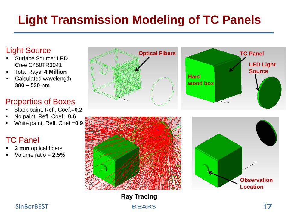
Light Transmission Modeling of TC Panels
Light Source Surface Source: LED
Cree C450TR3041
Total Rays: 4 Million
Calculated wavelength:
380 – 530 nm
Properties of Boxes Black paint, Refl. Coef.=0.2
No paint, Refl. Coef.=0.6
White paint, Refl. Coef.=0.9
TC Panel 2 mm optical fibers
Volume ratio = 2.5%
Optical Fibers TC Panel
Hard
wood box
LED Light
Source
Observation
Location
Ray Tracing
19 SinBerBEST
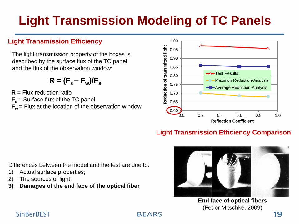
Light Transmission Modeling of TC Panels
The light transmission property of the boxes is
described by the surface flux of the TC panel
and the flux of the observation window:
R = Flux reduction ratio
Fs = Surface flux of the TC panel
Fw = Flux at the location of the observation window
Light Transmission Efficiency
R = (Fs – Fw)/Fs
Differences between the model and the test are due to:
1) Actual surface properties;
2) The sources of light;
3) Damages of the end face of the optical fiber
End face of optical fibers
(Fedor Mitschke, 2009)
0.60
0.65
0.70
0.75
0.80
0.85
0.90
0.95
1.00
0.0 0.2 0.4 0.6 0.8 1.0
Red
ucti
on
of
tran
sm
itte
d l
igh
t
Reflection Coefficient
Test Results
Maximun Reduction-Analysis
Average Reduction-Analysis
Light Transmission Efficiency Comparison
20 SinBerBEST
Conclusions
1. Translucent concrete (TC) can represent an energy efficient solution for
the building envelope.
2. Construction of the TC panel is feasible.
3. Daylight transmission properties of the TC panel is controlled by the
volume ratio of the fibers.
4. Light collection property of the TC panel can be improved by utilization of
convex lens and CPCs.
5. The bending of the fiber should be minimized as it affects the light
transmission performance.
21 SinBerBEST
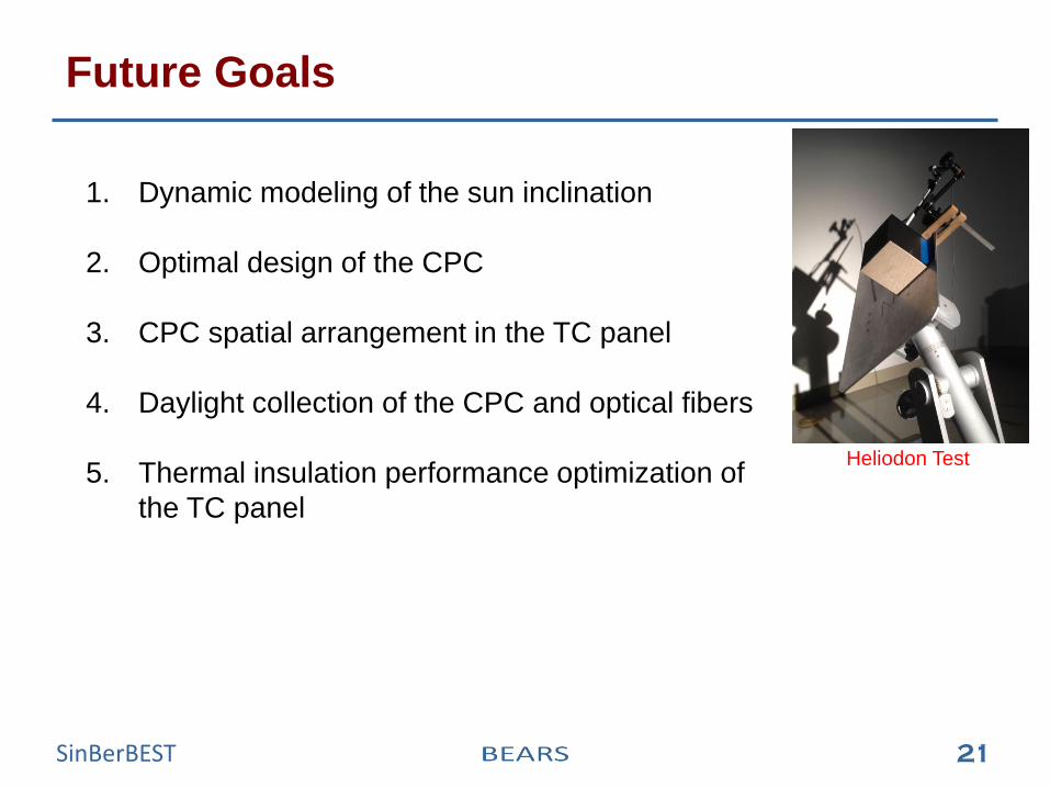
Future Goals
1. Dynamic modeling of the sun inclination
2. Optimal design of the CPC
3. CPC spatial arrangement in the TC panel
4. Daylight collection of the CPC and optical fibers
5. Thermal insulation performance optimization of
the TC panel
Heliodon Test
22 SinBerBEST
Thanks for your attention!
Questions / Comments?