Embed Size (px)
Citation preview


A n g e l o C o l o m b o - P i e r o B a l d a s s a r r i
YO U A R E N E V E R A LO N EO N T H E WAT E R
R a d i o w a v e s a t s e a : c o m m u n i c a t i o n s a n d e n t e r t a i n m e n t
o n b o a r d o f v e s s e l s

The idea for this small book has been driven by the fact that most manuals about tele-
communications in general and marine telecommunications in particular, are not easily
read and understood by those who, interested in the topic, do not want to go beyond
simple notions that allow them to understand the more important aspects of this matter.
It is clear that this is oriented to a reader that does not wish to become an engineer are or
specialised technician; we will be brief and, above all, we will look to avoid complicated
formulas. Nevertheless, it will be necessary to show some basic formulae, but this should
not scare our readers, because we believe understanding some formulae becomes an aid
instead of an obstacle.
The understanding is to provide a simple explanation of telecommunications phenome-
na, so everybody can easily interpret the technical data of an antenna when choosing one
from a vendor, for example.
We will explain things like gain and what determines it, and will also explain the different
modes to install an antenna, VHF or other type, to understand the potential even as a
function of position, in addition to its electrical characteristics.
I N T R O D U C T I O N

This said, there is nothing left but to start unravelling the mass of topics we find are the
essential arguments in a “Radio Electrical Guide for Leisure Boaters”, so we invite you to
continue, and expect that you will get to the last page having an idea of which antenna to
buy for your boat, where to install it to get the best performance, how to verify efficiency
and understand why sometimes you can communicate via VHF with friends 20 miles away
and sometimes you cannot, and why with some systems you can watch TV in all condi-
tions and with others you cannot.
After our analysis on telecommunications at Sea, we want to provide information on re-
creational navigation, that is, suggestions on what to verify before setting sail, advice
on what to have on board and what to leave behind, and, in short, make this a valuable
document to have onboard at all times.
We frequently have the opportunity to speak with people, to understand which things
they do not know and why it is cumbersome to try to differentiate between antennae.
This book will help provide the definitive answer to those questions.
Angelo and Piero

Thanks to Wayne Beak of Electronic Marine Solutions of Coomera Qld - Australia
for the review of the english version of “You are never alone on the water”
Angelo Colombo was born in Rome in 1967, where he currently lives and works as a
journalist. He started to sail at a very young age, and after 10 years a passion for the sea
lead him to join the Navy, where he worked as a radiotelegraph operator for 16 years, spe-
cialised in telecommunications and electronic warfare, and an undersea security expert.
After another 8 years in Navy units and about seven in service at land stations, in addition
to several years as skipper, he left the militarily life to pursue a life as a journalist, and
in particular, now for the international magazine “Nautica”. He collaborates with articles
under the heading “Coast Guard”, in which he writes about different topics regarding this
market sector. The sea and telecommunications have always been a passion and a job,
and for these reasons he continues sailing for sport and using radios as radio aficionado
and member of I.N.O.R.C. (Italian Naval Old Rhytmers Club). He connects with naval, aero-
nautic and land stations around the world, using frequencies that go from MF to UHF in
all digital and analogue modes.
Piero Baldassarri, born in Casola Valsenio (ITALY) in 1953, is head of Glomex, leader in the
production of antennas and entertainment systems especially developed for nautical use.
Piero Baldassarri has worked for several years at naval sites engaged in ship renovations;
he has sailed in Navy units and in 1978 founded Elettronica Azimut, a company dedicated
to the development of electronic systems and nautical and naval assistance; finally, in
1984, he founded Glomex. In addition, he was instrumental in the installation of all equip-
ment on the Test Lab, the laboratory boat where experiments are carried out on products
from the Ravenna Company to guarantee their quality.
A B O U T T H E A U T H O R S

Radio, Who and Why . . . . . . . . . . . . . . . . . . . . . . . . . . . . . . . . . . . . . . . . . . . . . . . . . . . . . . . . . . . . . . . . . . . . . . . . . . 8
Electromagnetic waves: What are they? . . . . . . . . . . . . . . . . . . . . . . . . . . . . . . . . . . . . . . . . . . . . . . . . . . . . . . 10
Frequencies . . . . . . . . . . . . . . . . . . . . . . . . . . . . . . . . . . . . . . . . . . . . . . . . . . . . . . . . . . . . . . . . . . . . . . . . . . . 12
Radio wave phenomena . . . . . . . . . . . . . . . . . . . . . . . . . . . . . . . . . . . . . . . . . . . . . . . . . . . . . . . . . . . . . . . . . . . . 12
Polarization . . . . . . . . . . . . . . . . . . . . . . . . . . . . . . . . . . . . . . . . . . . . . . . . . . . . . . . . . . . . . . . . . . . . 12
Reflexion . . . . . . . . . . . . . . . . . . . . . . . . . . . . . . . . . . . . . . . . . . . . . . . . . . . . . . . . . . . . . . . . . . . . . . . . . 13
Refraction . . . . . . . . . . . . . . . . . . . . . . . . . . . . . . . . . . . . . . . . . . . . . . . . . . . . . . . . . . . . . . . . . . . . . . . . . . 13
Diffraction . . . . . . . . . . . . . . . . . . . . . . . . . . . . . . . . . . . . . . . . . . . . . . . . . . . . . . . . . . . . . . . . . . . . . . . . 14
Absorption . . . . . . . . . . . . . . . . . . . . . . . . . . . . . . . . . . . . . . . . . . . . . . . . . . . . . . . . . . . . . . . . . . . . . . 14
Propagation . . . . . . . . . . . . . . . . . . . . . . . . . . . . . . . . . . . . . . . . . . . . . . . . . . . . . . . . . . . . . . . . . . . . 14
Gain . . . . . . . . . . . . . . . . . . . . . . . . . . . . . . . . . . . . . . . . . . . . . . . . . . . . . . . . . . . . . . . . . . . . . . . . . . 16
What is an antenna? . . . . . . . . . . . . . . . . . . . . . . . . . . . . . . . . . . . . . . . . . . . .. . . . . . . . . . . . . . . . . . . . . . . . . . . . . . . . . . 18
Where do I install a VHF antenna? . . . . . . . . . . . . . . . . . . . . . . . . . . . . . . . . . . . . . . . . . . . . . . . . . . . . . . . . . . . . 23
Transmission modality . . . . . . . . . . . . . . . . . . . . . . . . . . . . . . . . . . . . . . . . . . . . . . . . . . . . . . . . . . . . . . . . . . . . . . . . 24
Frequency modulation: FM . . . . . . . . . . . . . . . . . . . . . . . . . . . . . . . . . . . . . . . . . . . . . . . . . . . . . . . . 26
International Morse and phonetic alphabet . . . . . . . . . . . . . . . . . . . . . . . . . . . . . . . . . . . . . . 29
Regarding acoustic signals . . . . . . . . . . . . . . . . . . . . . . . . . . . . . . . . . . . . . . . . . . . . . . . . . . . . 32
Manoeuvre and warning signals . . . . . . . . . . . . . . . . . . . . . . . . . . . . . . . . . . . . . . . . . . . . . . 32
How to ask for aid using the radio? . . . . . . . . . . . . . . . . . . . . . . . . . . . . . . . . . . . . . . . . . . . . . . . . . . . . . . . . . . . . 33
T A B L E O F C O N T E N T S

Electronic safety . . . . . . . . . . . . . . . . . . . . . . . . . . . . . . . . . . . . . . . . . . . . . . . . . . . . . . . . . . . . . . . . . . . . 35
Our dear VHF . . . . . . . . . . . . . . . . . . . . . . . . . . . . . . . . . . . . . . . . . . . . . . . . . . . . . . . . . . . . . . . . . . . 35
EPIRB and rescue . . . . . . . . . . . . . . . . . . . . . . . . . . . . . . . . . . . . . . . . . . . . . . . . . . . . . . . . . . . . . . . . . . . . 42
Navtex . . . . . . . . . . . . . . . . . . . . . . . . . . . . . . . . . . . . . . . . . . . . . . . . . . . . . . . . . . . . . . . . . . . . . . . . . . . . . . 44
INMARSAT . . . . . . . . . . . . . . . . . . . . . . . . . . . . . . . . . . . . . . . . . . . . . . . . . . . . . . . . . . . . . . . . . . . . . . . . . . . . 44
DSC: What is it? . . . . . . . . . . . . . . . . . . . . . . . . . . . . . . . . . . . . . . . . . . . . . . . . . . . . . . . . . . . . . . . . . . . . . . 52
Radar: How does it work? . . . . . . . . . . . . . . . . . . . . . . . . . . . . . . . . . . . . . . . . . . . . . . . . . . . . . . . . . . 53
Sonar . . . . . . . . . . . . . . . . . . . . . . . . . . . . . . . . . . . . . . . . . . . . . . . . . . . . . . . . . . . . . . . . . . . . . 55
Nautical information . . . . . . . . . . . . . . . . . . . . . . . . . . . . . . . . . . . . . . . . . . . . . . . . . . . . . . . . . . . . . . . . . . . . . . . . . . . . 57
Meteorological information . . . . . . . . . . . . . . . . . . . . . . . . . . . . . . . . . . . . . . . . . . . . . . . . . . . . . . 58
The good leisure boater’s checklist . . . . . . . . . . . . . . . . . . . . . . . . . . . . . . . . . . . . . . . . . . . . . . . . . . . . . . . . . . . . 60
The essential checklist . . . . . . . . . . . . . . . . . . . . . . . . . . . . . . . . . . . . . . . . . . . . . . . . . . . . . . . . . . . . . . . . . . . . . . 61
Essential equipment and gear . . . . . . . . . . . . . . . . . . . . . . . . . . . . . . . . . . . . . . . . . . . . . . . . 62
Onboard radio and TV . . . . . . . . . . . . . . . . . . . . . . . . . . . . . . . . . . . . . . . . . . . . . . . . . . . . . . . . . . . . . . . . . . . . . . . . . 64
Y O U A R E N E V E R A L O N E O N T H E W A T E R

8
Navigators have always felt the need to communicate with land, not only for obvious
security reasons, but also personal well being and security. Spend a long time at sea and
you will know how good it feels to receive a voice call directly from the voice of a group
or a friend.
One thinks about visual signs, sounds and flags. Communication using to means at sea
can be critical to avoid dangerous situations; for example, two ships doing manoeuvres
can use sound signals to inform that they intend to go right by sounding the siren once,
and that they are going left sounding the siren twice -or sound the siren three times if the
skipper has issued the order “reverse engines”.
This is to say that communications has always been a topic of great importance for sai-
lors, either to exchange information at short distances or to communicate thousands of
kilometres away. Many scientific disciplines have contributed to the achievement to we
call radio; William Marconi was the first to integrate them, together with many data and
experiments by others, to be the first to solve this problem. William (Italian: Guglielmo)
Marconi, besides being a renowned physicist, was also a seafaring man, so he understood
the needs of those destined to be “always away” from home, land or medical assistance.
Because one of the problems facing sailors was to be able to have medical advice in real
time to avoid dangerous situations; today this is not a problem, we just call the C.I.R.M.
(International Radio Medical Centre) via telephone, VHF, HF, etc., but think of sailors a
little over a century ago, who did not have any means of communication and may be
20 days away from the first useful port where they could disembark a person in need of
assistance.
Let’s try to think what it meant to live without cell phones, without on-board VHF, without
coastal radio stations, without the ubiquitous radio and TV, without the incalculable in-
formation that are transmitted at all frequencies, and, more recently, EPIRB, GPS, etc., etc.
R A D I O , W H O A N D W H Y

9
Y O U A R E N E V E R A L O N E O N T H E W A T E R
Think that a little over a century ago all this was science-fiction, to the point that Marco-
ni’s experiments where the object of protests by some, who thought the waves emitted
by the big antennae used by this physicist in the Roman province were something that
could destroy mankind. To try to understand what we’re talking about, in the areas sur-
rounding Marconi’s experimental site, carbonized sheep were found, and the scientist
was deemed responsible due to his experiments. Naturally, it did not take much to show
that the reason for such an event was to search elsewhere, but initially the ghostly elec-
tromagnetic waves scared everyone, as the unknown usually does. At this point we want
to quote some words by William Marconi, who expressed in an interview the objective of
his studies: “I maintain my communications system will be used mainly and above all at
sea. Its use at sea will be indispensable”.
Today we are more or less familiar with this physical phenomenon, because we are used
to using telephone, radio, TV or a GPS receivers etc. Many do not understand the basic re-
asons why a sound signal such as voice can be transmitted thousands of kilometres away;
however we will seek to answer this question from a technical perspective, and explain
the basis of telecommunications.

10
To be able to define radio waves correctly it is necessary to go explain the building blocks
of matter - atoms.
Atoms look like a microscopic planetary system, with the centre being represented by the
nucleus around which electrons orbit.
The number of components in the nucleus, that is, protons and neutrons, determine the
characteristics of the different atom types. Electrons, which we have said orbit the nu-
cleus, are subjected to attractive and repulsive forces that, in balance, keep the atom
together; in addition, despite the nucleus having positive charge and the electrons nega-
tive change, their tendency to attract each other is compensated by other repulsive for-
ces that keep the atomic system in balance. In certain conditions some electrons detach
from the atom, with an external cause breaking this equilibrium we have just mentioned,
creating static electricity in a particular body, with the electrons being able to travel more
or less freely around these so-called conductor bodies.
When we consider that electron motion is variable, for example alternating, this creates a
magnetic field that changes with the same alternation, forming in turn an “electric field”
that will propagate in all directions at the speed of light, 300,000 Km/s, a value we will
henceforth refer to as C. Magnetic fields and electric fields have always been orthogonal,
that is, perpendicular, to each other. This type of electromagnetic propagation is called
a radio wave.
As we have said, these are waves, so as sea waves they have a crest representing the
highest point, and a trough representing the lowest point; the vertical distance between
them represents the amplitude, and the path from one point to the other is a cycle.
The number of cycles in a second represents frequency, whereas the distance between
two points of the same value is the wavelength. Therefore, it is necessary to express the
units of measure for frequency and wavelength. We use Hertz for the former, usually ex-
E L E C T R O M A G N E T I C W A V E S : W H A T A R E T H E Y ?

11
Y O U A R E N E V E R A L O N E O N T H E W A T E R
pressed as Hz, where 1,000 (103) hertz are indicated as kHz, 1,000 kHz as MHz and 1,000
MHz as GHz; we use metres for the latter.
At this point it should be underlined that the product of the multiplication of frequency
and wavelength is always C, or the speed of light. To offer a definite example, if we have
a frequency of 150 MHz or 150,000,000 Hz, we only have to divide C (300,000 km/s or
300,000,000 m/s) by f (150,000,000 Hz), and we obtain 2 metres, which is the wavelength.
Please bear in mind that, since the speed is usually expressed in km/s, it is more comfor-
table to use the frequency in KHz to get the result in m.
Explaining this is fundamental in understanding a good portion of the reasoning that
follows, because without an understanding of the relationship between wavelength and
frequency it is not possible to understand the operation of an antenna, since its physical
dimensions depend on wavelength.

12
The field of usable frequencies is called spectrum, and they take the name of audio, radio,
radar and other frequencies as a function of their utilisation. Conventionally, the spec-
trum is subdivided into bands, as follows:
F R E Q U E N C Y B A N D S
R A D I O W A V E P H E N O M E N A
POLARIZATION
As we have already mentioned, in radio waves the magnetic field and the electrical field
are always orthogonal to each other: in particular, the direction of current and the elec-
trical field always coincide. This happens in the type of antenna we are most interested
in analysing, the dipole. The electrical field determines the polarisation of radio waves;
for this reason, we will define as vertical polarisation a wave with a vertical electrical

13
Y O U A R E N E V E R A L O N E O N T H E W A T E R
field, and as horizontal polarisation a wave with a horizontal electrical field. For example,
the electromagnetic waves in our onboard VHF have vertical polarisation, whereas radar
waves have horizontal polarisation. Therefore, since two stations can communicate ef-
ficiently using the same frequency, they must use the same polarisation and the same
transmission mode.
REFLEXION
While they propagate through the air, radio waves reflect as light waves, more or less in
certain environmental conditions. All frequencies are subjected to reflection from the
ground or sea, their intensity depending on the angle of incidence with the surface, po-
larisation, frequency, and the composition and material quality of the reflecting surface.
The lowest frequencies, by their very nature, have less reflection capacity.
It should be noted that in reflections we can observe a phenomenon in which the phase
changes by 180°, circumstance that can generate interference and disturbance in the re-
ception due to phase differences between direct and reflected signals. This affects signal
quality/reception.
REFRACTION
Another important phenomenon is radio wave refraction, that is, the effect an energy
ray experiences when going from one environment to another that has different density,
especially if the ray comes from an environment having a greater density, the ray modifies
its direction. This phenomenon includes all frequencies, although those under 30 MHz are
subjected to a very modest effect.

14
DIFFRACTION
Diffraction is the effect experienced by a radio wave when it encounters an obstacle.
The result is the creation of a shadow zone in the direction of the propagation and the
irradiation of the obstacle itself, as well as obstacles further on, but with variations in the
radiation field. All this is much more evident the lower the work frequency is.
ABSORPTION
The intensity of the radiated electromagnetic field is inversely proportional to the distan-
ce from the source.
The reduction in intensity is defined as electromagnetic wave attenuation. Energy ab-
sorption is directly proportional to the frequency value; it also depends on the medium
being penetrated, whether it is sea, land or the atmosphere.
The problem of absorption is especially relevant for frequencies such as SHF, which are
usually employed in radar.
Attenuation is also affected by the phenomenon of scattering that is the reflection of air
molecules and weather conditions such as water vapour, rain, etc.
PROPAGATION
The term propagation defines the way in which radio waves move in the stratosphere
that covers the Earth with a thickness of approximately 400 km, which can be:
- in proximity to the Earth’s surface,
- in the space above,
Therefore, the electromagnetic waves radiated from an antenna are distinguished as:
- land waves,
- space waves,

15
Y O U A R E N E V E R A L O N E O N T H E W A T E R
Which in turn are subdivided into:
- direct waves,
- reflected waves
- surface waves.
We begin with the last one, surface waves, which are obtained when radiated electroma-
gnetic waves follow the Earth’s surface, which represents the conductor.
This propagation experiences a notable attenuation, which is much higher on land than
on the sea.
Surface waves are particularly useful with VLF and LF frequencies, which are very low fre-
quencies commonly used by ships operating far from the coast or by submarines, since
one of their characteristics is their ability to propagate very effectively, even in water.
Space waves are obtained when electromagnetic waves radiated into space above the
radiating element encounter the ionosphere with angles that curve their trajectory (re-
fraction phenomenon) to make it return to the Earth’s surface at a larger distance than
could have been achieved with a surface wave.
In this case a silence zone is inevitably created, or an area not reached by electromagnetic
waves; this area is called shadow zone, and the distance from the electromagnetic wave’s
starting point to its return point on the surface is called skip distance. It is interesting to
note that LF, MF and HF waves propagate either via surface or space waves, but with very
different effects and results. For example, LF suffers separation after surface propagation
and space propagation around 1,500 km, while MF, very sensitive to the type of antenna
used, has larger propagation distances at certain hours of the day. This is due to the fact
that, as a function of the time, the height of ionosphere strata, and thus their refraction
16
effect, varies, a phenomenon that in this case can produce fading, that is the effect by
which waves follow different courses, one surface and one space, reaching the receiving
antenna with opposite -and cancelling- phases. Then we have HF waves, which mainly
propagate through space waves, although during daytime hours one can also observe
their propagation via surface waves. If a radio wave is propagated in a vacuum, it would
follow a rectilinear course because there would be no phenomena regarding absorption,
refraction, reflection and noise, or interference encountered in the environment such as
lightning, engine flashes or other phenomena that generate electromagnetic fields and
chaotic progression, collected in our radio wave and propagated with it.
GAIN
Gain is one of the essential parameters for an antenna, and is expressed as value in dB, a
clear idea of the transmission and reception capacity of a radiating element. The referen-
ce used is the so-called isotropic antenna, which radiates electromagnetic waves of equal
intensity in all directions, and which is stipulated to have a gain value equal to 1 dB. To
understand the concept of isotropic antennae, imagine a sphere radiating from all points
on its surface. This type of antenna does not exist in practice, it is just an abstraction used
as reference. All real antennae are anisotropic, that is their radiation has a preferential
direction where they obtain maximum results. There are also highly directional anten-
nae, which transport the radiated bundle in a specific direction with variable amplitude
depending on the physical shape of the radiating element; for this reason they have very
high gain values. Therefore, gain, indicated as a number expressing a value in db, indica-
tes the intensity of radiation in the direction privileged by the antenna we are analysing,
17
Y O U A R E N E V E R A L O N E O N T H E W A T E R
taking into account that the reference is an isotropic antenna with the same power sup-
ply. In practice, if I provide 1 watt of power to an isotropic antenna at a given frequency,
I obtain a gain on the theoretical spherical transmission of 1 db; however, if for example I
use the same watt on a directional radiating element with a 14 db gain, the 14 indicates
that in the selected direction of the radio wave bundle we will have a greater yield com-
pared to that of any of the radiation points on our isotropic antenna. To calculate the re-
lation with performance there is a formula we omit to avoid complicating matters further,
but please near in mind that the reference value is that of an isotropic antenna. It is not
difficult to realise that the reference offers a clear idea about the features of an antenna.
To get higher gain values it is necessary to emphasise the transmission and reception
capacity of an antenna in a given direction; thus, for a radiating element of equal size, the
more directional an antenna is the greater its gain and the lower the amplitude of its tran-
smission unit. In practice, if you are able to transport a bundle of electromagnetic waves
in one direction and one direction only, you will obtain a higher gain. We need to clarify
something at this point, because some antenna manufacturers declare gain values that
are often obtained using calculation techniques different from the ones we have just
indicated, profiting from the lack of knowledge the general public has regarding these
facts. To have an accurate reference, always request that the gain be expressed in dB with
respect to our theoretical isotropic antenna.

18
Naturally, the gain factor also depends on other characteristics of the antenna, like its
physical makeup.
To offer a concrete and known example, TV antennae on the roofs of our homes are direc-
tional, so they have maximum performance in one specific direction that provides high
gain but must be pointed in the direction of the transmitting station.
This reasoning is also valid for omni-directional antennae, which sacrifice vertical tran-
smissions -that is, upwards or downwards.
Obtaining high gain values with this type of antenna depends on other factors besides
their physical shape. Thus, all dimensions are related to the frequency on which our an-
tenna will operate.
The physical the length of the radiant element depends on the frequency wavelength on
which it operates. In order to better understand this reasoning, we must necessarily make
a review and remember that the value of C or the speed of light, which is equal to 300,000
km/s, f or frequency, expressed in Hz or KHz, which allow calculating the wavelength by
means of a simple division.
Let’s retake the previous example for a frequency of 150 MHz, or 150,000 KHz, which has
a wavelength of two metres. Let’s bear in mind this reasoning, remembering that our
wavelength is equal to two metres.
Now we will try to explain, in simple terms, what an antenna is.
We have said previously that an electric signal is subject to field variations, in this case
determined by frequency, which in turn determines a variation in the magnetic field and
vice versa, giving origin to electromagnetic waves constituted by electric field rings alter-
W H A T I S A N A N T E N N A ?

19
Y O U A R E N E V E R A L O N E O N T H E W A T E R
nated with magnetic field rings perpendicular to each other. From an electrical point of
view, an antenna is a serial
resonant circuit, and by resonant we mean it is tuned to the frequency that it is using.
So, in summary, we can say that antennae are devices capable of converting electrical
signals into electromagnetic waves, radiating them into their surrounding space as well
as, obviously, receiving them.
The generator or transmitter produces an electrical signal that contains the information
to be transmitted, either in analogue or digital form, which is transported from our elec-
tric line or antenna cable to the transmitting antenna.
SWR: STATIONARY WAVE RETURN
It is the portion of the radio frequency that the antenna does not radiate due to the return
of stationary waves.
A 1.5:1 ratio is considered the maximum acceptable. Nevertheless, stationary wave re-
turns also depend on the position of the antenna, which must be at a minimum distance
of 1 m from any other metallic element. In different situations, the SWR value measured
on a boat can differ from the one measured in the laboratory.
HERTZIAN ANTENNAE
The first example of a radiating element was presented by Hertz, hence the name Hert-
zian antenna. It is an antenna whose total length is equal to half the wavelength, and in
which the line is divided into two equal parts. This type of antenna is very used in cellular
systems for radio bridges and transmitters, as well as in TV systems.

20
MARCONIAN ANTENNAE
The other antenna that is very commonly used is the Marconian antenna, which is com-
posed of a single rod whose total length equals one-fourth of the wavelength.
ANTENNA DIMENSIONS
Now, it is not difficult to imagine that at very low frequencies the wavelength has a very
high value, such as the case of LF; as seen in the frequency table shown before, we can
reach up to 1 km, which means, in the case of Hertzian antennae, a length of half a kilo-
metre for the radiating element, or 250 metres for Marconian antennae.
There are systems that allow having an operating antenna at similar frequencies that
overcome this problem; these systems allow obtaining what is technically called loaded
antennae.
This result is usually obtained with the addition of inductance or capacitance to the radia-
ting element, making it resonant at the frequency of interest.
This explanation is useful to understand why antennae vary so vastly in sizes.
Therefore, starting from our initial calculation on a frequency of 150,000 KHz, we have
said that the wavelength is 2 metres, so, logically, a Marconian antenna should not have
a length over 50 cm.
This is true but only in part, because experiments undertaken by those who have studied
this phenomenon demonstrate that an antenna can have dimensions are proportionally
larger, that is 1 m to be used at half the wavelength, or 2 m to be collinear, having the

21
Y O U A R E N E V E R A L O N E O N T H E W A T E R
same physical length as the wavelength; always proportionally, larger dimensions mean
better performance. Technically speaking, an antenna with a length larger than the wave-
length in which it operates must be adapted.
This is the case regarding the aforementioned shorter antennae, especially when we spe-
ak about high frequencies such as marine VHF, which operates around 156 MHz.
For this reason we have made our calculations and derived our considerations at a fre-
quency of 150 MHz.
“1 EURO FOR THE RADIO, 100 FOR THE ANTENNA”
Well, if you have read all you are now able to understand why, using two identical radio
devices with similar power but different antennae, you can communicate at great distan-
ces with one but not with the other. An old radio operator saying went more or less like
this: “spend 100 Lira on the radio but 1,000 on the antenna”. Lira were still used, and given
the amount this was not recently, so we updated the title. But this saying is still valid to
understand the importance of the antenna in the delicate issue of radio transmissions.
Many times I have heard comments like: “I must change the VHF antenna, so I’ll just get
one, since they are all the same”.
Nothing more wrong. An antenna with a 3 db gain will guarantee high omni-directiona-
lity but a markedly inferior performance compared to a 6 db or 9 db antenna. True, we
have to take into account how it will be installed; obviously, for the aforementioned de-
scription a 9 db antenna will have large dimensions, often about 7 metres, whereas a 3 db
devices does not reach one metre. But if it is to be installed on top of a sailboat masthead,
its broad transmission beam allows more effectiveness, even with a broken hull.

22
This demonstrates it is not true that they are all the same; the difference can also come
from the materials in which it is manufactured, now that we agree that each antenna is
unique.

23
Y O U A R E N E V E R A L O N E O N T H E W A T E R
Another element to take into consideration is the position of the VHF antenna, which
cannot be casual but a function of the calculations on the theoretical range, which we
will explain. Especially with respect to higher frequencies like VHF, UHF and SHF used in
radar, propagation is by means of direct waves. Therefore, as we have already hinted, they
propagate as light waves, that is, with a visual range. There is a simple formula to calculate
the theoretical capacity of transmissions at very high frequencies, from which we have an
idea of the different results obtained by mounting an antenna on the stern deck instead
of on the masthead.
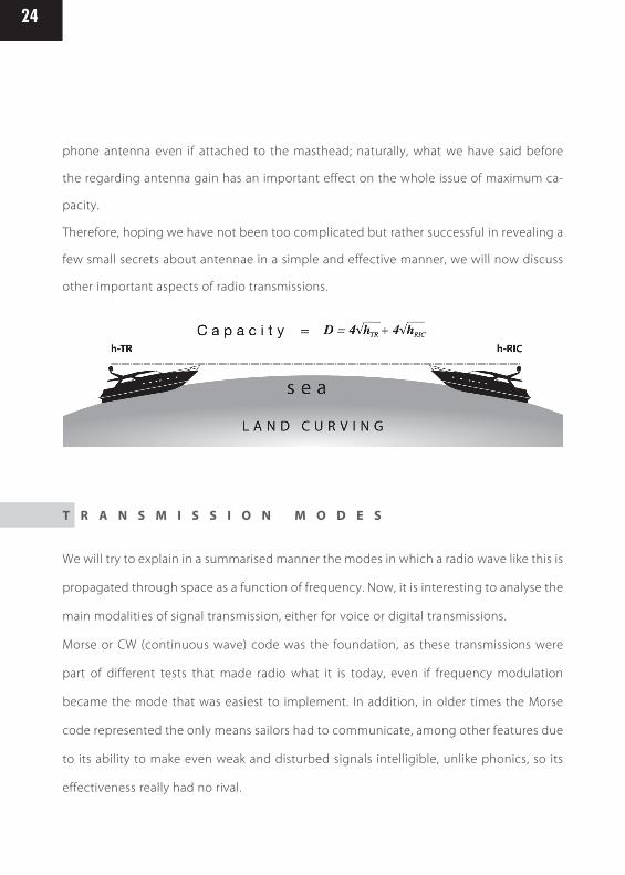
The formula is Where R is the theoretical communications
distance expressed in km, 4 is a fixed factor, htr is the height, in metres, of the transmitting
antenna and hric is the height, in metres, of the receiving antenna. This formula takes
into account the possibility offered by radio frequency to propagate beyond the optical
horizon due to the effect of diffraction, but we must consider it the maximum attainable
for safety reasons.
Therefore, we are now calculating the possibility of making a long-distance connection
with VHF between two ships, one of which has the antenna placed on the masthead;
let’s say 9 m high, the other with engine and the antenna placed at 4 metres on the fly.
Applying the formula above we have 12+8 = 20 km, equivalent to 10.79 miles. Now, we
can apply the same formula to two sailboats with the antenna on the masthead, always 9
metres high; the result would be 12+12 = 24 or 12.95 miles.
Or we can install them on the stern deck of two sailboats, let’s say at 2.25 m from the sur-
face; we obtain 6+6 = 12 km or 6.47 miles. It is not difficult to understand the importance
of antenna position in addition to its electrical characteristics.
It is useless to say that the distances just mentioned are just the maximum obtainable,
which means one can not expect to communicate and such distances with a small cell
W H E R E D O I I N S T A L L A V H F A N T E N N A ?
24
phone antenna even if attached to the masthead; naturally, what we have said before
the regarding antenna gain has an important effect on the whole issue of maximum ca-
pacity.
Therefore, hoping we have not been too complicated but rather successful in revealing a
few small secrets about antennae in a simple and effective manner, we will now discuss
other important aspects of radio transmissions.
We will try to explain in a summarised manner the modes in which a radio wave like this is
propagated through space as a function of frequency. Now, it is interesting to analyse the
main modalities of signal transmission, either for voice or digital transmissions.
Morse or CW (continuous wave) code was the foundation, as these transmissions were
part of different tests that made radio what it is today, even if frequency modulation
became the mode that was easiest to implement. In addition, in older times the Morse
code represented the only means sailors had to communicate, among other features due
to its ability to make even weak and disturbed signals intelligible, unlike phonics, so its
effectiveness really had no rival.
T R A N S M I S S I O N M O D E S

25
Y O U A R E N E V E R A L O N E O N T H E W A T E R
Also taking into account a problem that was highly prevalent in the past due to the com-
plexity of the devices used then, a Morse transmission required a lot less power to be ef-
fective compared to other modes, in particular amplitude modulation (AM) or frequency
modulation (FM).
We will not dwell in the matter to explain this rather simple phenomenon, but it should
suffice to know that Morse, using an international code, allowed communications even
across language barriers.
Today, satellite allowed communications using relatively low power and with an ease
that was unfathomed at the time. In addition, in time other transmission modalities were
developed for radio transmissions, including fax, written messages, photo images and
video feeds. In short, technological progress has taken over part of all radio transmissions;
however, in the world and there is still a great number of people then use it to communi-
cate, especially for recreational purposes but also including Navy applications.
Everybody has an idea about the fact that one time the rescue signal was identified as
SOS, but few know all that in reality this signal was born of the needs related to the musi-
cality of the Morse code: the S is composed of three points, that is three very short pulses,
whereas the O is composed of three lines or long pulses, so SOS was easily identifiable
regardless of the type of traffic or disturbances because of its distinct rhythm, ti ti ti ta ta
ta ti ti ti, where ti are points and ta are lines.
The meaning of the SOS acronym is Save Our Soul, a clear request for help. Well, let’s go
now to the modality that is most used today, in particular the ones we usually have on
board our boats, such as frequency modulation (FM) with our VHF, cell phones, commer-

26
cial radio signals using the band from 88 to 108 MHz, land video and satellite signals, etc.
Then we will talk about transmissions using lateral bands, like SSB for Singe Side Band,
which in turn is subdivided into USB (Upper Side Band) and LSB (Lower Side Band). We
will also deal with transmissions in amplitude modulation (AM), used by commercial radio
on medium and short waves, and by aeronautical communications as well as by truckers
using the CB band.
Therefore, there are different modalities that allow transmitting from one point to other
written messages, such as ISB or Independent Side Band, used by transmissions in FSK or
Frequency Shift Key, which is the one used in telex.
There are also on digital transmissions, like the ones used by the new DSC system in the
latest VHF and MF/HF equipment used to meet SOLAS regulations; they allow to simul-
taneously transmitting with a rescue message the name of the transmitting station or its
GPS position.
There also are fax transmissions, allowing the reception of the famous meteofax.
In short, the modalities to use radio waves are really many, but we will try to analyse only
those of greater interest to sailors who navigate only for the pleasure of it.
This transmission modality is widely used because its characteristics make it quite immu-
ne to disturbances, interference and similar. Our VHF uses it, and as anyone can attest,
signal transmission and reception is clear and does not require any type of adjustments.
We do not want to make a technical explanation, among other reasons because it would
be a useless exercise, but it is necessary to understand an element: as in amplitude
F R E Q U E N C Y M O D U L A T I O N : F M

27
Y O U A R E N E V E R A L O N E O N T H E W A T E R
modulation or AM, when we press the transmission button or PTT (Push to Talk), the
power radiated from our device is the one for which it was regulated. Therefore, with
devices using 1 Watt or 25 W, the important thing to keep in mind is that this power is
radiated even when not speaking if we have the microphone PTT pressed. It is not difficult
to understand that power consumption and heat generation depend a lot on the dura-
tion of the communication.
We have intentionally mentioned the phenomenon of the power supplied by our device
during an FM or ATM transmission, to explain some reasons why frequencies such as HF
or MF should use other modalities like Singe Side Band (SSB).
These are two modalities, (LSB), as well as the Independent ISB). In practice, this type of
transmission only uses a portion of the signal generated by the device, becoming, quite
simply but clearly, much lighter.
The first result is a signal that can make better use of the transmitter’s power to be sent
into the air, consequently increasing the useful connection distance with respect to the
power used. The second result is that, unlike FM or AM, the power being delivered directly
depends on the intensity of the signal coming into the microphone capsule.
For example, to verify the power of our transmitter, we whistle into the microphone,
because the capsule excitation with a whistle is at its maximum level, so the excitation of
our transmitter is adjusted by emitting at the available power.
One of the advantages of this feature, in addition to performance regarding the distance
travelled by our signal, is that during pauses between the transmission of words or letters
our transmitter “relaxes”, that is, emits very low, almost negligible power, so the power
S S B
28
generating elements heat less, absorb less and last more. Speaking about transmission
modes, we wanted to deal with this topic by highlighting the practical characteristics of
FM and AM compared to SSB, because we have heard many times there is a need to have
SSB on board.
The use of SSB in vessels that intend to navigate at great distances from the coast, except
satellite transmissions, insures contact with land through connections to coastal radio
stations around the world, either for emergencies or to make a phone call using the radio
device. In addition, this type of devices allows having access to a great deal of information
transmitted by military and civil stations around the world on meteorological conditions
and forecasts, navigation notices and general news. But we will talk about that later on.

29
Y O U A R E N E V E R A L O N E O N T H E W A T E R
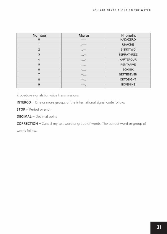
M O R S E C O D E A N D P H O N E T I C C O D E
We want to talk about the Morse alphabet because its characters are often used in sound
communications, for example: E to indicate going right, I to indicate going left, and S to
indicate reverse engine. The following tables also show the International Phonetic Alpha-
bet, the only one that allows “spelling” a word, so you can be certain that anyone will be
able to understand what was said. A very important part is the numerical portion of the
phonetic alphabet, because often numbers are essential components of a transmission,
like when communicating the vessel’s geographical position, or when transmitting an ETA
(Estimated Time of Arrival) including date and time. The letters and numbers of the inter-
national phonetic alphabet are often used, even by those who speak the same language,
because since they are generated from a phonetic point of view, they allow avoiding
confusion and misunderstandings, like for example between M (Mike) and N (November).
It may it difficult to learn them all, but reality if you try to use the International Phonetic
Alphabet while reading a text, you will arrive at the end of the page already being able
to remember a good portion; in time, it will become as simple as the alphabet we all
learned as children. It is not difficult to understand the reasons for the creation of the
International phonetic alphabet; on the other hand, we find that even in flag signalling,
for example, the white-blue flag is ALFA and not A, indicating that the vessel exposing it
has a submarine operating close to the ship or under it. In this respect we will dedicate a
table to indicate the meaning of the main visual signs using flags.

30
31
Y O U A R E N E V E R A L O N E O N T H E W A T E R
Procedure signals for voice transmissions:
INTERCO = One or more groups of the international signal code follow.
STOP = Period or end.
DECIMAL = Decimal point
CORRECTION = Cancel my last word or group of words. The correct word or group of
words follow.

32
R E G A R D I N G A C O U S T I C S I G N A L S
We are now going to indicate the manoeuvre and warning signals used by vessels.
For ‘.’ we understand a short whistle blow, and for ‘-‘ a longer whistle blow, like the Mor-
se alphabet but using the boat’s whistle.
MANOEUVRE AND WARNING SIGNALS
There are other sound signal used, for example, in conditions of scare visibility, but we
prefer to limit ourselves to those already mentioned and not complicate matters too
much.

33
Y O U A R E N E V E R A L O N E O N T H E W A T E R
H O W T O A S K F O R A I D U S I N G T H E R A D I O ?
From now on we must clarify the nature of different messages from ordinary communi-
cation. There are three types of messages: urgent messages, safety messages and help
messages. The first is a message distinguished by the PAN prefix, repeated three times
and followed by the text.
This type of message is an immediate alarm about a circumstance that is of a dangerous
nature, for example there is a seriously wounded person on board and immediate medi-
cal intervention is required; however, the situation does not entail sinking or abandoning
the ship, so it can navigate safely. This message must necessarily contain the ship’s posi-
tion, the nature of the emergency and update on the situation.
This message can also be issued by the Harbour Office, for example, when aware of the
potential danger to a vessel about which there are no news, in order to alert the units
going through the area in question.
Safety messages, often broadcasted on VHF channel 16, especially in winter, are characte-
rised by the prefix Sécurité repeated three times, warning that important information will
be broadcasted regarding the safety of navigation.
A classic example is a tree trunk sighted by a vessel after a storm close to a river mouth.
In this case, the emitting station must insert in the message the cause, and in the specific
case of the drifting trunk the motion characteristics of this navigation danger.
For example: “tree trunk sighted, approximately 4 metres long, partially visible on the
water surface, at position 42.25.00 North – 012.34.00 East, drifting with SW course and
estimated speed of two knots”.
Let’s go now to our rescue message, that is the one telegraphs represented by SOS, and
which, using phonics with our VHF, will be represented instead by the words MAY DAY
with a French pronunciation, like it were written ‘MEDE’, three times before emitting the

34
message content. The information that must be transmitted before any other is: name
of the calling station, position of the ship at the moment of issuing the message, nature
of the emergency, current condition of the vessel and crew, type of help requested, if it
is just the ship or if medical assistance is necessary, plus any other information that can
help the rescuers.
A classic request for help follows:
MAY DAY – MAY DAY – MAY DAY
Here ship BAHIA (repeated three times)
MAY DAY BAHIA
Position 42.25.000 N – 012.43.000 East
Severe break down in hull centre, request immediate assistance. We intend to abandon
ship in five minutes. No one with serious injuries. No wounded on board, crew of four
people.
BAHIA vessel, over.
Therefore, a clarification is necessary, for this is not the classic scheme rigidly bound to
procedures; in fact, observing it we see that it includes additional information like the
number of crew members, because if the Coast Guard were to send a rescue helicopter
because the shipwreck is too far for a ship to get there on time, it needs to know how
many people are on board for safety reasons. In practice, you anticipate an explicit re-
quest by the other party, speeding up the communication time, which in these cases is
usually very brief; also, because a sinking ship usually has electric issues which in a few

35
Y O U A R E N E V E R A L O N E O N T H E W A T E R
seconds can render the boat and radio unusable, and it is not always feasible to make
contact using a mobile. Naturally, this type of communication must necessarily use re-
scue channels, which we remind you are channel 16 in VHF, corresponding to frequency
156,800 MHz, and the MF frequency called 2182, 2,182 KHz in SSB. If the emergency takes
place close to the coast, and can be reached by GSM signal, the single number for Co-
ast Guard, 1530, can be called, connecting the caller immediately to the nearest centre
equipped for sea rescue.
MARINE VHF
VHF devices, whether fixed or portable, are radio electric appliances operating within the
marine band going from 156,025 MHz to 162,025 MHz. As per international organisations,
this band is divided into channels. In similar areas channelling is obtained by adopting
quartz, which insures the response will use a certain pre-established frequency. In practi-
ce, channel 16 works on frequency 156,800 MHz, this is applicable to all, including other
channels. Always talking about channels, we must make a distinction between simplex
and duplex. In fact, there are channels that operate in just one frequency, that is, both the
receiver and transmitter operate on the same frequency- these are simplex channels.
Obviously, to be able to receive it is necessary to interrupt transmission, for pressing the
PTT (Push to Talk) inhibits the receiving unit. Instead, duplex channels transmit at one
frequency, which is always 156 MHz, receiving at a different, higher frequency; in fact,
signal reception in duplex channels occupies a band portion that goes from 160,625 MHz
to the upper limit indicated for the band, 162.025 MHz. We will speak about channel 16 in
more detail below, but regarding updates in international regulations and thanks to the
E L E C T R O N I C S A F E T Y

36
adoption of increasingly evolved instruments, today there is another rescue channel, 70,
which anticipates the use of selective digital calls for rescue and safety purposes. But we
will talk about this in more detail later in the chapter dedicated to the DSC system, which
is part of the GMDSS or Global Maritime Distress Safety System. Let’s go back to our du-
plex channel. We have said that the transmitting module in the device uses a frequency
and that the receiving module uses another.
This selection allows, for example, telephone communications using VHF, for the land
station that sorts the call can leave its transmission open even when their on-board con-
tact starts talking, because their devices operate in the opposite manner, transmitting in
the frequency we use to receive and vice versa. These communications are called duplex
notes, but they do not have the same modality
as cell phones, since when our device is transmitting it inhibits reception. Telephone
communications are said to be in full duplex, but we say this to explain the operational
differences between both systems.
We now list the frequencies and channels corresponding to the marine VHF band; many
will never have use for it, but if you had to use a device that is not really nautical and uses
continuous tuning, you at least have reference values for the frequencies to enter. This is
also valid for a those who, with and on-board VHF, want, for example, to listen to other
channels in the band using a scanner -that is, a receiver.
It should be noted there is no channel listing from channel 28 through channel 69. It
seems useless to talk now about the reasons for this choice, but it must be taken into
account to avoid questions like “why doesn’t my device operate on channel 30?” (In this
case the answer would be “because it does not exist”. The table we have also allows
knowing which channels to use for a communication between us and another vessel;

37
Y O U A R E N E V E R A L O N E O N T H E W A T E R

38

39
Y O U A R E N E V E R A L O N E O N T H E W A T E R
after our first contact on channel 16, we immediately give our contact a working channel,
which must be necessarily a simplex channel. But when we call a land station to requests
a call by a radio, we should not be surprised if the communication is through a duplex
working channel, for the reasons stated before. Below we list the 47 port authorities on
our coasts, which listen on channel 16 and the channel we indicate. We also provide the
telephone and fax numbers of their marine divisions.

40
Just imagine being able to see on your radar display, with overlaid electronic chart data,
every significant ship within VHF radio range, each with a velocity vector (indicating spe-
ed and heading), actual size of the vessel, with position to GPS or differential GPS accura-
cy, ship name, course and speed, classification, call sign, registration number, MMSI, mane
vering information, closest point of approach (CPA), time to closest point of approach
(TCPA) and other navigation information, more accurate and more often than ever before.
Display information available previously only to modern Vessel Traffic Service operation
centers could now be available to every AISequipped vessel. With this information, you
not only see other vessels in the region, but they also see you when you use an AIS tran-
sponder. Just like riding a motorcycle, you may be vigilant and alert, but how often are
accidents caused by others not seeing you. Just like ships running over vessels in Major
channels. So what is AIS? The AIS is a shipboard broadcast system or transponder, opera-
ting in the Marine VHF, which is capable of handling well over 4,500 reports per minute
and updates as often as every two seconds. It uses Self-Organizing Time Division Multiple
Access (SOTDMA) technology to meet this high broadcast rate and ensure reliable shipto-
ship operation Each AIS system consists of one VHF transmitter, two VHF TDMA receivers,
one VHF DSC receiver, and standard marine electronic communications links (IEC 61162/
NMEA 0183) to shipboard display and sensor systems. Position and timing information is
normally derived from an integral or external global navigation satellite system (e.g. GPS)
receiver. Other information broadcast by the AIS, if available, is electronically obtained
from shipboard equipment through standard marine data connections. Heading informa-
tion and course and speed over ground would normally be provided by all AIS-equipped
ships. Other information, such as rate of turn, angle of heel, pitch and roll, and destination
and ETA could also be provided. The AIS transponder normally works in an autonomous
and continuous mode, regardless of whether it is operating in the open seas or coastal
A U T O M A T I C I D E N T I F I C A T I O N S Y S T E M ( A I S )

41
Y O U A R E N E V E R A L O N E O N T H E W A T E R
or inland areas. Transmissions use 9.6 kb GMSK FM modulation over 25 or 12.5 kHz chan-
nels. Although only one radio channel is necessary, each station transmits and receives
over two different channels to avoid interference problems, and to allow channels to be
shifted without communications loss from other ships. The system ensures communica-
tions integrity is maintained even in overload situations. Each station determines its own
transmission schedule (slot), based upon data link traffic history and knowledge of future
actions by other stations. A position report from one AIS station fits into one of 2250 time
slots established every 60 seconds. AIS stations continuously synchronize themselves to
each other, to avoid overlap of slot transmissions. Therefore those stations which sudden-
ly come within radio range close to other vessels will always be received by those vessels.
The system coverage range is similar to other VHF applications, essentially depending on
the height of the antenna. Its propagation is slightly better than that of radar, due to the
longer wavelength, so it’s possible to “see” around bends and behind islands if the land
masses are not too high. A typical value to be expected at sea is nominally 30 nautical
miles with a high performance antenna. With the help of repeater stations, the coverage
for both ship and VTS stations can be improved considerably. People make the common
mistake by assuming that any old VHF antenna will do the job with AIS operation. AIS uses
Channel 87B (161.975 MHz) and Channel 88B (162.025 MHz), whereas the centre frequen-
cy for VHF Marine is 156 MHz. Therefore if an antenna manufacturer designs the antenna
to be resonant higher than the normal VHF – in fact 161-162 MHz, then far greater per-
formance can be expected from AIS. And after all, it is a safety system, and the further it
reaches the better, so accurate antenna choice is vital. In summary, you can expect AIS to
become mandatory eventually on most small/medium to large vessels, and for all those
Ocean going people that spells peace of mind.
42
EPIRB or Emergency Position Indicating Radio Beacon is an emergency transmitter of the
COSPAS-SARSAT satellite system, using Russian and US satellites in almost polar orbits for
marine purposes.
One of their main characteristics is to float and be equipped with an automatic activation
system using a hydrostatic release mechanism. The signal transmitted by EPIRB operates
in the aeronautical rescue frequencies 121.5 MHz and 406.025 MHz, emitted from satel-
lites and received by land stations called L.U.T. (Local User Terminal), which process the
signals receives and gather data on localisation before everything to the MMC (Mission
Monitoring Centre) for distribution and SAR organisation.
These devices, when acquired or replaced, must be coded by organisations in charge of
these operations and registered in a database that can be accessed when needed to pro-
vide additional information to rescue teams. The database of the Italian satellite station
is locates in Bari.
Currently tests are being carried out to give Inmarsat geostationary satellites the ability
to receive rescue signals coming from these devices on the 406 MHz band, allowing im-
mediate reception of that signal by land stations immediately after beacon activation. It
is interesting to observe that, along the Italian coast, at least 13 MRSC (Maritime Rescue
Sub Centre) are present in Genoa, Livorno, Roma-Fiumicino, Naples, Reggio Calabria, Bari,
Ancona, Ravenna, Venice, Trieste, Catania, Palermo, and Cagliari.
These centres guarantee each for their jurisdiction zone, rescue operations according to
directives and specific delegation of functions. Regarding the sea rescue chain, at a lower
level we find the Port Command or Harbour Office, Maritime District Offices and Mariti-
me Local Offices, all identified as Coast Guard Units and suitably equipped to provide
E P I R B A N D R E S C U E

43
Y O U A R E N E V E R A L O N E O N T H E W A T E R
aeronautical rescue in their respective areas. For example in Italy, besides using VHF or
MF devices to request help, the phone number 1530 can be used 24/7 year-round; this
number is capable of automatically forwarding the call to the nearest rescue centre. All
this activity is coordinated and controlled by the operative unit in Rome, which counts on
modern means to clarify the situation in real time, including the position of the vessel to
be rescued and the boats getting close to it.
The operation room of the Coast Guard is able to know, in real time, the location of each
vessel in transit in the local area of competence, allowing it to contact the one closest
to the shipwreck and ask it to provide aid if this is the fastest and best solution for this
particular case. Considering that all coastal stations are listening on VHF channel 16, and
then it would be a good norm for all ships and water crafts equipped with VHF devices to
make sure they listen on this channel, possibly using the “dual watch” function all devices
have and which allows listening to two different channels at the same time.
This must be a rule because we can contribute to save a life, and also because channel 16
is internationally recognised as a rescue call channel, that is the channel a vessel or land
station can use to communicate with us and then provide a working channel.
Another good rule is to never use this channel for conversations with other stations, for
this would prevent listening on rescue calls; channel 16 is used to establish initial contact
and then a working channel is communicated, nothing more.
This said, it is essential to know that, in order to make sure a rescue call will be listened,
absolute silence periods are anticipated, during which no calls except rescue calls can be
made on channel 16. These periods are identified in the first three minutes of each half
hour, or from 00 to 03 and from 30 to 33.

44
Navtex is a radio telex service used to broadcast information on safety issues and the we-
ather to those vessels travelling along the coasts that are served by this system.
This is not a device that is standard in most recreational vessels, but it is good to know
that it exists.
It is a receiver that operates on the 518 KHz frequency, and by means of a processor that
can distinguish the transmissions of interest it allows printing the messages received, so
you can always control the notices coming from coastal stations.
This device is mandatory aboard commercial vessels since 1993, but not for leisure craft;
however, there are many charter yachts with a length over 24 metres that fall into the
normative mandating its use.
Inmarsat is a satellite communications system that has been in operation for some time;
it uses geostationary satellites located at 36,000 km of altitude to insure communications
coverage between 70° S and 70° N.
In addition, a chain of land stations adequately positioned along coasts around the world
(for example, the station located in Fiumicino) guarantee land-ship radiotelephony and
telex communications and vice versa. With this
system it is possible to access the telephone network thanks to the land stations, which
are connected using subscriber lines. In case of emergency communications, priority ac-
cess is given to the satellite communication pathways; it is possible to obtain this feature
by means of digital codes, as well as those within the framework of GMDSS.
N A V T E X
I N M A R S A T

45
Y O U A R E N E V E R A L O N E O N T H E W A T E R
The standard in use with the Inmarsat satellite network is Standard A, representing the
first one guaranteeing high-quality telephone, telex, fax and data traffic.
Then Standard B was developed, which guarantees the same services but at a higher
speed, representing a low-cost alternative to Standard A.
Then we have Standard C, which can provide data exchange services with the use of
small, lightweight terminals that use small omni-directional antennae and can reach data
transfer speeds up to 600 kbits/sec.
Another widely used Standard is Inmarsat-M, which provides digital telephony services,
fax and the possibility of data exchange through compact terminals, although it has been
almost completely replaced by the Mini-M Standard.
This one is a compact digital telephone with fax and data exchange system. Similar in
shape to a small laptop, it offers data transfer speeds of up to 2.4 kb/s and is ideal for a
great number of leisure boaters. The GAN (M4) standard was presented quite recently; it
guarantees data exchange with a speed up to 64 Kbps.
One of the things that should be pointed out for all Inmarsat standards is that the proto-
col used for data transmissions provides secure communications, which cannot be inter-
cepted by third parties.
Another satellite telephony system proposed by Thuraya Satellite Telecommunications
Company based on geostationary satellites and alliances with major international mobile
telephony operators. This system allows connecting to land or satellite telephony services
via a single terminal with dimensions similar to those of a cell phone.
T H U R A Y A

46
Prices for this system are very competitive, and even in this case we find a communica-
tions solution that allows transferring voice data wherever you are. Given its characte-
ristics, it is one of the systems most widely used by war correspondents and journalists
operating in desert areas; one reason is that it can connect to a GPS network, being able
to broadcast the terminal’s position if needed.
VSAT is Very Small Aperture Terminal. It is a bidirectional satellite communications system
that allows using antennae smaller than 3 metres in diameter. VSAT’s technology insures
bandwidth that is currently not available with other systems, being able to guarantee
high-speed connectivity for multimedia applications that require broadband.
Among its uses we have the possibility of videoconferencing on board, which is feasible
in great extensions around the globe, including remote areas.
Among the features that distinguish this satellite communications system we have solu-
tions like TDMA (Time Division Multiple Access) and BoD (Band on Demand).
These solutions permit the elimination of additional hardware requests, reducing instal-
lation costs for the whole system and insuring effective management and better interfa-
cing with land networks.
In this case we are talking about a technology that is already offered by one of the ope-
rators that have espoused the VSAT cause, developing a platform that can be directly
integrated into different network typologies, even supporting Mesh, Star and Virtual Star
connections.
In short, the potential of the VSAT system resides mainly in the generous bandwidth that
is available, as well as ample footprint and future development thanks to international
V S A T

47
Y O U A R E N E V E R A L O N E O N T H E W A T E R
agreements between operators. But this is not all, because this technology already offers
many dedicated services like telephone calls and Internet connections, at costs that are
decidedly much better than in the past.
Acronym of Global Positioning System, it is also called Navstar (Navigational Satellite Ti-
ming and Ranging). GPS is nowadays commonly used and is one of the preferred naviga-
tion systems. This system allows, using global, continuous coverage, the position of the
receiver in three dimensions, latitude, longitude and altitude. This information is obtained
by means of calculations executed by our device on measurements regarding distance
and time between at least three satellites (triangulation). Naturally, to be able to do all
this it is necessary to have a particularly accurate system to measure time; in fact, all sa-
tellites are synchronised among themselves and with land stations, using atomic clocks
with almost no variations that prevent evident calculation errors. The working frequency
for orbiting satellites, which will be 21 plus 3 in reserve, follow 6 circular orbits with a 55°
inclination with respect to the equator and staggered between them at 60°, at 1,575.42
MHz for L1 and 1,227.6 MHz for L2.
The signals transmitted by the space platforms are coded so each satellite can be iden-
tified and perfectly synchronised. Taking note of the transmission speed for electroma-
gnetic waves, that is the speed of light, C or 300,000 Km/sec, a measurement of time will
immediately give distance. Thus, the principle is based on the time needed by the satelli-
te to reach the receiver that we have on hand or on our boat bridge. In order to make this
G P S

48
calculation, our receiver must use the same time slot as the satellite, synchronising when
the device connects to the system. In order to offer data on the accuracy of the clocks
used by the GPS system, their variation is about 10-13 sec. /day. Receivers, whether fixed
or portable, come with very sophisticated software that can select data regarding the
satellite they are receiving from, but since the device clocks are very inferior in terms of
accuracy compared to atomic clocks, they have to be continually corrected.
With three data pieces simultaneously from three different satellites it is possible to de-
termine one’s position without any ambiguity. The GPS system is managed by the United
States, which offer two different precision protocols from the so-called C/A system for
commercial users, and P, for limited users, among them the military. The expected de-
viation for the system does not exceed a radius of 3 metres, but it is necessary to point
out that at moments of particular international tension certain areas may be subject to
the introduction of deliberate errors by the US administration that manages the system.
This is why the DGPS (Differential GPS) system was introduced, by which the problem of
SA or intentional degradation is virtually eliminated. GPS receivers have other functions
besides receiving satellite signals, such as processing data by directly providing position
coordinates, the speed of the vessel where the device is located, altitude and course. All
this is possible thanks to the possibility of always knowing, with absolute accuracy, the
ephemeris or all satellites in altitude, that is their relative position.

49
Y O U A R E N E V E R A L O N E O N T H E W A T E R
Galileo is an alternative to the Global Positioning System or GPS, whose characteristics are
being a global navigation system that was fully developed in Europe, so unlike GPS it is
not subject to the control of the US Department of Defence.
It is expected to be fully operational by 2013, and will be based on a network of 30 sa-
tellites orbiting on three inclined planes on the equator, at a distance of approximately
24,000 Km from the Earth’s surface.
The objectives of the agencies that developed it are to guarantee more accuracy with
respect to the network currently available, better signal coverage (especially at higher
latitudes), a global positioning system that can operate without limitations, even during
international tensions or conflict.
The Galileo program was officially started on 26 May 2003 with an agreement signed
between the European Community and the European Space Agency (ESA). After interna-
tional crises some European countries have been in favour of freely using the current sy-
stem rather than financing the development of Galileo, but Italy and France in particular
continued maintaining their position in favour of the new system.
The full cost of the project will amount to 3 billion Euros, which include building land
stations and the launch of 30 orbit positioning satellites. It should be noted that in 2003
Chine joined the initiative with an investment of about 230 million Euros; the state of Isra-
el became a project partner in July 2004. Many speak about the involvement of numerous
other countries, like Chile, Japan, Brazil, India, South Korea, Australia, Morocco and Cana-
da, while Russia is thinking about integrating Galileo to its GLONASS system.
Satellite launches have already started; the first was set in orbit in December 2005. It was
called GIOVE for Galileo in Orbit Validation Element. Another two satellites will be placed
G A L I L E O
50
in orbit to be able to start technical tests on radio frequencies and clock stability; then
another two satellites will be launched and positioned to complete the in-orbit verifica-
tion and validation program for Galileo.
It should be noted that the accuracy of the clocks on board the satellite units is essential
to provide accuracy for the positioning; for this reason atomic instruments will be cou-
pled to signal amplifiers.
One of the features of Galileo is that it will be able to count on a constellation of satellites
capable of providing Earth-based geographical position data of the highest quality in
addition to platforms that can also be used for communications.
In fact, the Galileo system is the core of a system to be implemented in time to offer in-
tegrated services that encompass from surveillance to territory control, supporting legal,
insurance, tourist and agricultural activities.
All this is possible thanks to the multiple applications that can be developed for the pla-
tform, which today already provide an effective control of the position as well as aeronau-
tical vectors, guaranteeing safe takeoffs and landings even in critical visibility conditions.
The maritime sector will contribute to the development of the AIS, or Automated Identi-
fication System.
Undoubtedly, Galileo is a useful instrument for safety at sea, in the sky or on the ground,
thanks to the high reliability it can insure. Another important feature of Galileo is that is
allows the creation of a unique European number for rescue calls, E-112, thanks to which
rescue teams will have the possibility of tracking, with extreme accuracy and in real time,
the position of the caller.

51
Y O U A R E N E V E R A L O N E O N T H E W A T E R
Globalstar is a system that uses 48 low-orbit (about 1.410 Km) satellites. It is important to
mention because it was the first system that successfully integrated with GSM land net-
works, making it the first system to use a satellite hand phone.
Globalstar is used by the armed forces and companies that need to remotely contact their
operation units even in inaccessible areas.
It has been particularly effective thanks to the so-called Path Diversity and Soft Hand Off
technologies, which prevent call drops thanks to the simultaneous use of two or more
satellites.
Acronym of European Mobile Satellite Phone, Emsat is a mobile satellite communications
system that covers the whole Mediterranean basin, including Central and Northern Euro-
pe. The capacity of the satellite network implemented by this system is 4,800 kbit/s, much
more than common ADSL but less than the new HDSL, which goes up to 155 Mbit. Tele-
phony management is provided by the Italian company Telespazio; Emsat’s hub station
is even located in Italy and managed by the same company. The terminals are quite ro-
bust and can be interfaced using RS232 connections to a PC, sensors or fax terminals;
unfortunately, they are very costly.
The Iridium system was developed to make sure that anywhere on the planet it would
be possible to use cellular telephony, using for this purpose a large network of some 66
satellites. In this case the satellites have low altitude, being at approximately 780 Km from
the Earth’s surface, which can guarantee communications with a quality similar to that
G L O B A L S T A R
E M S A T
I R I D I U M

52
of land systems, since there is no latency associated to networks that use geostationary
satellites. The Iridium system is quite valid because where it is located it uses the common
GSM network; where there is no GSM it uses satellite networks, guaranteeing telephone
connections. Iridium is the most expensive satellite communications system, but also the
most sophisticated.
Another of its features is that, even in case of disasters such as hurricanes or earthquakes,
the system ensures effective connections; this is why it is one of the most widely used
rescue systems when there are disasters.
Digital Selective Call, better known as DSC, is a modality used by naval vessels to emit
danger signals and by land stations to confirm the reception of these signals.
This function is also used to re-emit rescue signals, that is messages on emergency si-
tuations but which are not directly generated by those requiring aid. In practice, if while
navigating we receive a help call and perceive no one is acknowledging receipt, they are
obligated to reemit the help message received by means of the MAY DAY RELAY procedu-
re. DSC is an integral part of the GMDSS and is used with MF, HF and VHF devices.
A message issued with this technology is constituted of the numerical address of the
station being called, the caller’s own self-ID, and text containing all relevant information
such as nature of the danger, position and time, for example. The message thus transmit-
ted is preceded by a series of points and a sequence that allows fixing on the receiver.
The whole procedure to process these messages is completely automatic and is execu-
ted in a short time to ensure rapid intervention. At his point we must necessarily make
clarifications, since there are different commercially available devices equipped with DSC,
but this does not mean one just needs to buy one to be able to use this technology. As
D S C : W H A T I S I T ?

53
Y O U A R E N E V E R A L O N E O N T H E W A T E R
previously stated, data identifying the transmitting vessel or its international registration
is simultaneously transmitted with the rescue message forwarded via the DSC.
If a station emits a message lacking these elements, said message is not considered re-
liable and the emitter may face severe penalties. Therefore, a nonregistered water craft,
which obviously has no international registration associated to a nationality, cannot use
this system. It goes without saying, but water crafts can very well use VHF channel 16
when the distance from the coast at which they are normally found does not require
accelerating procedures for the exchange of rescue messages, as is sometimes the case
in oceanic navigation.
Nowadays, we are somewhat used to seeing radar antennae even on very compact ves-
sels. It should be taken into account that, only during the last 20 years, thanks to the evo-
lution in electronics, there has been success in making such devices particularly efficient
in spite of relatively modest current absorption and the general components of the devi-
ces. The principle of how a radar functions is based on the concept of reflected wave, in
other words, the electromagnetic wave that, on impact upon an object, which from this
point forward we will call target, returns to the point of origin, that is, our radar’s antenna.
The first experiments on radio localization systems were conducted on frequencies nowa-
days considered extremely low for such a purpose, yet, at the time, generating elevated
frequencies was not a simple task. Progress has led to the possibility of the usage of very
high frequencies, the SHF, which, as we have seen before, occupies a range that goes
from 3 to 30 GHz. Such frequency values ensure adequate characteristics of propagation
and reflex for the specific purpose of the radar.
Above all, their propagation comes by direct waves, as well as by linear waves, and is their
R A D A R : H O W D O E S I T W O R K ?
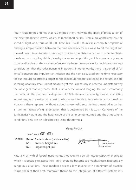
54
return route to the antenna that has emitted them. Knowing the speed of propagation of
the electromagnetic waves, which, as mentioned earlier, is equal to, approximately, the
speed of light, and, thus, at 300,000 Km/s (ca. 186,411.36 miles), a computer capable of
making a simple division between the time necessary for our wave to hit the target and
the real time it takes to return is enough to obtain the distance datum. In order to obtain
the datum on mapping, this is given by the antenna’s position, which, as we recall, can be
strongly directive, at the moment of receiving the returning wave. It should be taken into
consideration that the radar transmits in packets, in other words, there is a period of “si-
lence” between one impulse transmission and the next calculated on the time necessary
for our impulse to attract a target to the maximum theoretical scope and return. We are
speaking of a truly small unit of measure, yet this is necessary in order to understand why
the radar gets that very name, that is radio detection and ranging. The most commonly
used radars in the maritime field operate at 9 GHz, there are several types and capabilities
in business, as this writer can attest to whomever intends to face winter or nocturnal na-
vigations, these represent without a doubt a very valid security instrument. All radar has
a maximum range of signal detection that is determined by 4 factors - Curvature of the
Earth, Radar height and the height/size of the echo being returned and the atmospheric
conditions. This can be calculated by using this formula:
Naturally, as with all board instruments, they require a certain usage capacity, thanks to
which it is possible to assess their limits, avoiding become too much at ease in potentially
dangerous situations. These modern devices allow anyone with a minimum of practice
to use them at their best, moreover, thanks to the integration of different systems it is

55
Y O U A R E N E V E R A L O N E O N T H E W A T E R
possible to superimpose the radar image upon mapping, for example, by making our
computer do everything that was once done with a grease pencil and so much patience
by hand.
The echo-sounder is an electronic instrument that allows us to arrange precious pieces of
information from the depths of the ocean below our ship. The elements that integrate it
are: the transmitter, the receiver/amplifier and the transducer. While the first two compo-
nents are part of the device, the third element is applied to the hull and linked by cable
to the calculation unit. Also in this case, we come across a system the uses reflection as
a base phenomenon, but with water as the element upon which the signal is irradiated,
rather than using a radio frequency that would not offer great results unless it is too low
and with notable complications; thus, a sound wave is used. In the practice, our transmit-
ter emits an electric impulse transformed into a sound impulse by the transducer, which
leaves the bottom of our scope, reaches the ocean floor and returns to its origin, in order
to become an electrical impulse once again and sent to the receiver. At this point our
computer, practically the mind of our device, transforms, through a series of calculations,
the amplified signal of the receiver into a video signal. There are several types of echo-
sounders in business, their efficacy and quality may be generally considered very high;
also, speech integration is part of this type of instruments. In the practice, thanks to multi-
functional monitors currently available in the market, we are able to have immediate and
simultaneous access to navigation data from our cartographic GPS radar, radar data and
echo-sounder images. This device proves very useful for lovers of fishing who have the
possibility of assessing the quality of the ocean floor above which they intend to operate
S O N A R

56
in order to see fish schools passing by represented, yet, above all, as a navigational aid
for safety purposes to rule out dangers deriving from impact with the ocean floor. Having
the awareness that there is a quantity of water underneath adequate for our hull enables
us to get away from situations that may reveal themselves to be catastrophic. Modern
devices are also capable of looking towards the stern, that is, to provide us with a graphic
anticipation of the ocean floor we have head, therefore, it is easy to sense how precious
this information can become while navigating unknown waters and above ocean floors
characterized by highly changing bathymetric values.
The plotter has become a very commonplace device; it is composed of a multi functional
monitor on which it is possible to see the real time information originating from several
sensors such as the GPS, the radar, the echosounder.
All of these pieces of information from the most modern systems are superimposed to
digital cartography, which renders navigation truly simple for anyone, in terms of calcula-
tions which are all performed by the computer. It is needless to say that it is good to be in
the extent of providing to perform said calculations also autonomously, inasmuch as one
cannot trust one’s own luck to system that relies totally on electrical power.
Some, to rule out such danger, carry with them always two devices, for example, a reserve
cartographic portable device to insert into the Panic Bag in case of need.
Nowadays the norm in force acknowledges digital cartography as valid cartography for
navigation purposes, which, for a technical standpoint, does not create a fold given the
level of reliability and the existing possibility of updates, yet who writes deems it appro-
priate to also carry traditional cartography on board, the quadrants and the compass,
even only to trace the ship’s position every half hour, keeping a historical, which, if nee-
ded, will allow us to know with precision where we were exactly at that particular time.
T H E P L O T T E R
57
Y O U A R E N E V E R A L O N E O N T H E W A T E R
For example, if there is a sudden abandonment of the ship during which our reserve
device ends up in the water, our ship’s main feed will be diminished and all we have to
communicate where we are is a portable VHF device and a map with our ship’s location
not more than half an hour old.
Now, take the ship’s position that is no older than 30 minutes and attempt, under these
conditions, to provide your approximate position, which you may be able to retrieve by
going over your route and your speed at the moment of the incident. Without the refe-
rence of the ship’s position, the result will be a series of numbers that will not help much
those who would come looking for us, compelling them to do research that may take
more time than necessary to aid anyone who has been injured in an appropriate manner.
In any case, electronic navigation truly allows anyone to navigate safely under normal
conditions; modern devices are reliable and their precision is always more accurate than
the position’s graphic representation.
In short, progress has truly provided us with great
assistance; however, we must not forget the rules of traditional navigation, but we should
not exclude the possibility of having to use it in case of emergency conditions.
As we stated at the beginning of our tour, several decades ago, the possibility technology
offered for the exchange of information between a means of navigation and land were
decisively limited. Nowadays, thanks to the development of technology and the decre-
ase in prices due, also, to the vast distribution of the devices, we can rely on numerous
sources of nautical information. Let’s take a look at them together. There is a system
entitled WWNWS, which stands for World Wide Navigational Warning Service, dedicated
to the diffusion of Urgent Notices to Mariners. This system has been elaborated by IMO
N A U T I C A L I N F O R M A T I O N
58
and by IHD (International Hydrographic Organization), with the purpose of coordinating
the nautical diffusion by radio within geographical areas marked by a NAVAREA number,
throughout the Mediterranean and the III. Urgent Notices to Mariners are divided in three
categories: great distances, coastal and local. We must consider that in order to have ac-
cess to general nautical information, one can take advantage of the radio transmissions
operated by RAI through FM frequencies, and, moreover, remember the inexhaustible
sources of the Internet, where one can find updated weather information from major
international weather institutes, beginning from, for example, the website www.eurome-
teo.com, which includes satellite images, wind charts and anything that may be useful
to planning safe navigation. The next step is a very important consideration and must be
kept in mind every time we are at sea. Hydrographic Services are, almost exclusively, the
ones that provide the diffusion of nautical information, even when it has been originated
by other sources, such Port or Military Authorities, Lighthouse Services, etc., yet one of the
most important sources of information is always the navigator, regardless of the reasons
for which he/she is out at sea. Therefore, when we observe a potential danger, or we be-
come aware of non-compliance between what is signalled in the cartography and what
is not verified at sea, we are under the obligation of pointing it out. This may be done by
reporting to the port authorities if what we have observed does not constitute immediate
danger, however, under different circumstances, the nearest coast guard station should
be notified through VHF channel16.
The sources of meteorological information are divided in three categories: synoptic cha-
racter, operative character and statistic-climatic character.
M E T E O R O L O G I C A L I N F O R M A T I O N
59
Y O U A R E N E V E R A L O N E O N T H E W A T E R
Synoptic sources are used by meteorologists for the study of physical-climatic charac-
teristics in the atmosphere. Operative sources are specific to for all operative activities
geared at, mainly, assisting aerial and maritime navigation. Statistic-climatic sources are,
however, geared at the study of weather conditions in certain geographic areas.
The main sources of meteorological information are divided, in turn, in warnings, wea-
ther and sea condition forecasts, brief and general weather forecasts of average maturity.
The reception of this information may result, as we have mentioned earlier, through the
VHF device, disseminated in a circular way through channel l68 and in the schedule of
local channels. As mentioned earlier, this information may also be received through the
NAVTEX device. We see what the warnings and the advisories are. These are messages
that contain information relating to phenomena regarded as dangerous for navigation,
emitted with absolute precedence above any other message with the exception of emer-
gency/rescue messages. There may be strong wind advisories, subclassified into gale,
storm or hurricane warnings. There may also be warnings of thunderstorms, whirlwinds,
tropical cyclones or ice at sea.
Their transmission is set to take place at previously fixed schedules by coastal radio sta-
tions which are in charge of the diffusion of the warnings/advisories. The forecasts are
divided into three very different parts: advisories, situations and forecasts/tendencies. We
have already seen what the advisories are in case these are to be transmitted in an iso-
lated fashion; regarding the situation, we find the summary description of the pressure
and front areas present in the maritime zone should be considered. The last part, the one
pertaining to forecasts/trends, we find data forecasts on wind and visibility. The most
detailed Meteomars also provide data on the state of the sea, by coding a series of SYNOP
message, which include the observations of the coastal stations. Meteomar is transmitted
in the national language and in English; this is valid in every country.
F O R E C A S T S

60
Before you give up on your moorings, it is important to carry out a general check-up of
the vessel and everything on board that may represent a potential danger or a safety in-
strument, be it for a long cruise as well as for a short one. The norms to take into account
should not be interpreted as impositions, they actually are an instrument to safeguard
one’s own as well as others’ safety. The first indication to follow, even prior to getting on
board, is the inspection of the current weather conditions and forecasts for the area in
which one intends to navigate.
These are available near the harbour-offices, yet they may be received 24 hours a day
through VHF channel 68; there is also the transmission of other information through other
channels that may be useful to know. The Meteomar allows us to have a clear and con-
stantly updated picture of the local and general weather situation, which puts us in the
condition of taking the necessary precautions in terms of our anticipated route, and shun,
T H E G O O D L E I S U R E B O A T E R ’ S C H E C K L I S T

61
Y O U A R E N E V E R A L O N E O N T H E W A T E R
possibly, having to modify the planning of our cruise for safety reasons. Nowadays, thanks
to the Internet, access to weather information is absolute; however, arriving at the dock
without having an idea of what awaits us from the meteorological point of view is not an
excuse of any kind.
1. Verification of general hull conditions, conditions of all manholes and all systems for
opening and closing;
2. Verification of state and maintenance of the floorings;
3. Verification of conditions of air tanks and buoyancy;
4. Verification of plugs and sea cocks;
5. Verification of status of scuppers and all water ways;
6. Control and verification of bilge pumps, electrical and manual;
7. Control to discover possible water infiltrations be it from the hull or from the deck;
8. Verification of maintenance of gasoline tank, the plug and the generator up to the
engine pump;
9. Verification of the conditions of all fixed and current manoeuvres;
10. Verification of the state of deck fixtures, of the chain or chains and of all sea shanty
equipment;
11. Verification of the state of stanchions, supports and life belts;
12. Verification of operation of navigation lights, and of acoustic signalling devices;
13. Survey of the tools and spare parts present on board;
14. Manual verification of carburetion and water levels;
15. Operation and control test of radio device connections;
16. Accumulator control: cleanliness of contacts, level of liquids, voltages and plug main-
tenance;
17. Cleanliness of the vessel and possible discharge of combustible material which is not
strictly necessary (see alcohol);
18. Verification of the state of identifiable unit elements, that is, serial number, name and
conditions of the nationality flag.
T H E E S S E N T I A L C H E C K L I S T

62
These are the fundamental indications to keep in mind every single time one intends to
face the sea, naturally, these come together with the specific experience on the ship itself,
which allows the acquaintance of the vessel’s weak points which require special atten-
tion. Below, we would like to recall which equipment and supplies are critically necessary
to have on board to face navigation.
1. Life vests for all people on board;
2. Life buoys ready to use;
3. Anchor with line and chain proportionate to the ocean floors above which one intends
to operate;
4. Efficient oars and stanchions;
5. Magnetic compass subject to periodic inspections;
6. Updated nautical charts and publications;
7. Fire extinguishers ready to use and easily accessible in case of need;
8. Flashlights, flares and other visual distress signals, stored and in serviceable condition;
9. Water-proof torch with new batteries;
10. First aid kit containing specific medication non included in the list provided by law,
but which may prove useful during the course of navigation;
11. Knife endowed with a serrated blade;
12. Matchsticks, preferably of the waxed kind, since they can better resist wind and also
last longer than other kinds;
13. Drinking water in adequate quantity and nourishment in accordance with the situa-
tion and the passengers;
14. Auto-inflatable device checked and ready to use, yet, above all, positioned in such a
way as to place it at sea in the quickest and safest way;
15. Preparation of an airtight container in which to put in supplies in case of ship aban-
donment, called Panic Bag.
E S S E N T I A L E Q U I P M E N T A N D G E A R
63
Y O U A R E N E V E R A L O N E O N T H E W A T E R
T H E P A N I C B A G
Auto-inflatable lifeboats are provided with a similar item and contain a knife, fishing line,
waxed matchsticks and other essential elements regarded as fundamental for survival.
The panic bag that we will endeavour to put together prior to facing challenging naviga-
tions is a more thorough task. Above all, its container must be airtight. Among those that
lend themselves for such operations, for the most part, we find the small plastic trunks
used for the conservation of foodstuffs; these trunks are endowed with a screw cap top
which ensures proper keeping. Once this container has been found, our next objective is
to become acquainted with shipwreck conditions, that is, to succeed in supposing which
could be the items that could offer us the highest degree of survival possible, since this
is and must always be the highest objective of a shipwreck, to survive. Naturally, the very
first thing is the water, understanding that Alain Bombard, French doctor who became
a voluntary castaway to demonstrate that he would be successful in living by behaving
in a manner opposite to the indications at the time, during the fifties, considered guide-
lines of a medical nature. He demonstrated that it is possible to imbibe sea water; the
trick lies in how to drink it; he demonstrated, furthermore, that one may extract water by
squeezing prey caught with rudimentary systems; he also demonstrated that survival is
the result of delicate physiological balances that do not exclude the castaway’s psycho-
logical condition, which should always aim at survival to be rescued and not found. All
of this can be found in the book he authored after this, his audacious adventure, whose
title is “Voluntary Shipwreck”. We come back to our panic bag, we have identified water
as the first element to put into our precious container, then, surely, instruments to define
our ship’s position, from the portable GPS to the sextant, also a multifunctional knife in

64
stainless steel, fishing material, a portable VHF with fresh batteries, packed yet energy
food, such as energy bars, tinned food, well-kept sugar or honey, small but robust caps,
plastic containers. These are the fundamental items to put into a preventive panic bag,
in other words, a container to have easily reachable in case of emergency. Nevertheless,
one must consider that every object becomes an instrument to use in an emergency, in
other words, during the phases that precede the abandonment of the ship. In practice,
a member of the crew will be in charge of carrying a container, a rucksack, a bag, a sack
and to put everything that contains items essential for survival on board a life boat. This
is the panic bag, and its usage must be, thus, a rational one. The commander, once on
board the lifeboat, will count the members of the crew and will make the daily rations,
and, further on, organize fishing activities as well as the collection of condensed and rain
water. It is important not to take objects that may endanger the integrity of the lifeboat,
such as unprotected sharp objects.
ONBOARD TV
For several years now, the use of television has been imposed also on board of pleasure
crafts, thanks to the decrease in prices and, above all, the simplification and decrease of
the devices’ encumbrance. In the market, we may find LCD or plasma video to the degree
that you may find any type of device for any type of pleasure boater, as well as how radios
of every shape and size are available in stores. For all, however, when it comes to evices
that have the ability to decode and give shape to radio signals, problems of a technical
nature are the same. We shall endeavour to see what these issues are about and how
O N B O A R D R A D I O A N D T V

65
Y O U A R E N E V E R A L O N E O N T H E W A T E R
to solve the most common ones. As we have already seen in regards to radio signals,
particularly those of high frequency commonly used for the transmission of some that
emit radio and TV signals, these are propagated directly, however, they are sensitive to
natural phenomena and situations that may lead to a loss in efficacy among these, as they
renter the terrestrial curvature. As with all high frequency VHF and UHF signals, in order
to be well received, that is, with all the information that allows getting a good video tran-
smission or commercial radio signal, they require, above anything else, a good antenna.
Moreover, a good antenna down stroke is necessary, that is to say an appropriate cable
and which is in condition to absorb only a minimal part of the received signal; these are
called low attenuation cables and are used particularly for all applications in which the
frequencies at stake are very high, as in the case of VHF or UHF frequencies, which are
commonly used for radio and TV signals. However, in time television has also found other
alternative ways of broadcasting to the classical analogical terrestrial broadcasting, the
same one which, for decades, we all received in our houses. One type of broadcasting
which is very similar, though also more recent, is surely digital terrestrial broadcasting,
which is a type of broadcasting that allows the viewing of different shows from those
that are broadcast by the conventional analogical network besides applications that are
possible thanks to digital technology, such as entertainment shows, and others. This type
of signals, as all those that are digital, are particularly sensitive to field variations, that is,
that their nature is very sensitive to a decrease in the signal received. Just to mention
the example, perhaps closer to home for all those individuals who use their cell phone
at sea, when we used the analogue phone, the ETACS, that is, we could communicate in
an agile way even at a great distance from the coast, but with the change to GSM, this
great advantage has ended. The reason is found in the nature of the transmitted signal,
which, since it is of a digital nature, part of the information loses the entire «message»,
as opposed to the analogical signal, which allows, however, rendering even weak signals
understandable. Digital transmission comes from the flow of information in packets, each

66
of which contains part of the transmitted information, if these packets arrive in a confused
or incomplete manner; the entire content of the message is lost. With the analogical sy-
stem, part of the information may be lost, but the rest of the information is received. The
adopted synthesis by the author in order to explain this phenomenon is drastic, yet that
which, for the most part concerns us in this matter is to make the practical differences
between a system and the other understandable, instead of the theory that interests only
a few; in the practice, the owners of the transmitter may send every frequency with minor
power/potency, minor maintenance costs and electrical energy to 6 digital channels. In
any case, going back to our digital television, in order to make the signals become ima-
ges on our TV set, they must be of good quality, since, as we have already seen, the first
ingredient of the recipe is surely a good antenna, then the down stroke and, finally, the
devices due to which TV sets and decoders are not all the same as the 200 € television
set, which derives for a computer monitor, could not possibly have the same sensitivity
as a true 600 € TV set would, and the same rings true for the more economical decoders.
Another way of broadcasting TV signals is by satellite at around 12 GHz; this system allows
overcoming the barrier imposed by the terrestrial curvature and by the zones not in reach
of the broadcast of terrestrial radio locations.
Also in this case, we come face to face with a system that requires the adequate antenna,
and by adequate we must interpret, nonetheless, anything that is a big gain, inasmuch as
the satellite must always be seen by our parabolic antenna and that implies a particular
function, which is targeting. During the last few years, several companies have bestowed
it upon themselves to produce antennae capable of getting and maintaining contact
with the satellite pre-selected for the viewing of TV channels, even if there are only a few
companies capable of producing antennae that allow the viewing of a TV show without
interruptions during the course of navigation. The issues to solve are a quick search of
the satellite, the targeting, and the upkeep of the signal even after route variations, or
in spite of any other elements of motion, a high gain. From this perspective, these seem

67
Y O U A R E N E V E R A L O N E O N T H E W A T E R
like minor issues; however, in reality, the companies dedicated to the development of
this type of solutions have had to carry out numerous experiments in order to be able
to reach the levels nowadays found and, nevertheless, not attainable by everyone. One
of the problems that, for the most part, afflicted this type of systems was linked to the
speed of search and securing a signal; this is solved through the adoption of circuits
and solutions that have replaced systems such as the traditional gyrocompass, nowadays
developed electronically, which makes it faster and, above all, insensitive to those atmos-
pheric phenomena that, before, conditioned its operation. In order to quickly hook up to
a satellite, it is necessary to become acquainted with its ephemera, that is, the position in
space regarding that of the equipment on which the antenna has been installed in real
time, in order to carry this out, one needs a processor capable of tapping into a database
which, in turn, would provide it with data about the satellite’s position; this data will have
been elaborated in function of our unit’s position, taking the antenna to the exact point
at which the satellite is positioned.
All of this takes place in a few instants; this relates to the elaboration of digital data, and,
nowadays, commercial processors are very fast. Recapitulating, it is necessary to know
where the satellite is, target the antenna towards it; we recall the antenna is strongly
directive 2/3 degrees in order to obtain the maximum performance possible, reach the
satellite, decode it and send the signal to our TV set, while ensuring that our antenna will
be capable of remaining connected to satellite, in spite of the movement of the ship. The
antennae used for this type of applications are mounted on two axes, a vertical and a ho-
rizontal axis; therefore, a good antenna should have also particular characteristics linked
to the type of movements besides guaranteeing an adequate performance. However, this
is not all, since the entire system for signal reception is not the antenna alone; actually,
in conjunction with the aerial element that we will install over our bar or fly; it is also ac-
companied by a central unit in charge of ensuring the elaboration of the data necessary
to guarantee good TV viewing while at sea. We have accomplished an extreme synthesis

68
of the showing of TV shows at sea; one should also consider that nowadays, as opposed
to the past, one can watch all of the shows that were frequently viewable only at home
or on firm ground only; moreover, thanks to technological development, many antennae
are also able to operate with satellites that distribute long bandwidth signals in for high-
speed Internet access.
AM/FM RADIO
Regarding the reception of commercial radio signals, the speech does not differ much
from the one done generically by antennae, one must consider that radio broadcasting
takes place over very low frequencies, such as, for example, MF and HF, or such as is the
case of FM frequencies over VHF frequencies from 88 to 108 MHz

69
Y O U A R E N E V E R A L O N E O N T H E W A T E R
Therefore, even in this case, the antenna makes the difference, and also, in this case, we
find all types in stores, even if, as mentioned earlier, not all antennae are the same. En-
tertainment on board pleasure crafts is rapidly evolving, from the systems that operate
locally, to those that avail themselves of analogical and digital radio signals; for this to
happen, it is necessary to have the devices adequate so that the viewing of a TV show or
connecting to the Internet will be a source of pleasure and not bad moods.
MUSIC ON BOARD
Music is one of the arts that one may not renounce to during moments of relaxation;
therefore, numerous companies have set themselves to the task of producing devices
that support the stress linked to the marine environment. In the past, analogue cassette
players, then CD’s, have represented the support thanks to which it was possible to listen
to one’s favourite music at any time. The arrival of digital music, initiated by CD’s, has al-
lowed, nonetheless, taking alternative paths, such as, for instance, that of the well-known
MP3 files, which, through compression, guarantee hours and hours of music in volume
of contained space. Such technology has imposed an adaptation also on the devices
that allow us to listen to it, thus, MP3 file readers, always smaller and more powerful for
their functions yet also capable of memorizing a great amount of data and reproducing
these at our will. In this case, we are dealing with devices that can memorize and produce
music, movies, video games, files, computer programs to face needs in the workplace
also while being away from one’s habitual residence, in short, the true and very integra-
ted entertainment systems. The advantage is that, rather than having more devices, thus
more feeding lines and cables that go round the vessel, with only one system, we have
everything that is intended for our entertainment.
70
We conclude our tour on the analysis of radio transmissions at sea with a chapter dedica-
ted to the products by the Glomex Company. Above all, we feel the need to point out that
this is one of leading world companies in the projection and production of sea antennae
systems. It is not just a case in which the company’s products are favourably welcome by
numerous international sites, which regard Glomex as one of the benchmark suppliers for
the equipment of the ships they produce. The list is very long, yet it suffices to go to any
harbour to notice the Glomex brand, with which the corporation personalizes each one of
its products, from the simplest to the most complex products. It is interesting to point out
that Glomex offers a warranty with each one of the products it markets, which speaks at
length of the quality of the materials used, in fact, it is a lifetime warranty over nearly the
entire range of products the corporation releases with the product, only because it does
not harbour any doubts on the raw material used on the assembly of the parts, inspected
piece by piece by the technicians that nowadays operate in accordance with corporate
quality standards of absolute relief.
As regards the electrical quality of Glomex antennae, it is guaranteed by a projectile de-
velopment brought forth by the owner’s experience as a navigator and as a technician,
coupled with the skills of highly qualified staff that is dedicated to the research and the
development of cutting-edge solutions. From this work in laboratories, besides the op-
timization of the products prior to inserting them in the market, come the antenna sy-
stems evolving around the reception of TV, radio and Internet signals, destined to equip
moving vehicles. Since Glomex, in fact, has a leading role in the marine field as a leader
in the membership sector, it turns also to the automobile market, in particular to the RV
segment. In what regards the task of projection and construction, the materials chosen
and, thus, the guarantee, they are perfectly identical. The philosophy which, since the be-
ginning, corporate management has pictured in order to develop a product line destined
to ensure communication for moving vehicles, is to manufacture serial products destined
to guarantee communication for moving vehicles in the best way possible, ensuring pri-
ces in line with the global value of the goods on which they should be installed. In the
G L O M E X A N D I T S P R O P O S E D A N T E N N A E

71
Y O U A R E N E V E R A L O N E O N T H E W A T E R
practice, this is a choice that has required a systems development that, besides being
qualitatively free of concessions, must be carried out with industrial processes capable of
containing costs. Research, development and precision engineering all contribute to the
reason Glomex is so successful today.
Presently, we intend to propose a vision on many products by the Corporation at Ra-
venna, all of which are intended to guarantee efficient communication or moments of
relaxation on board vessels, Recreational Vehicles or other moving vehicles. Production is
divided into antennae for radio communication, thus, VHF, SSB, AIS, ORBCOMM, CB and
GSM cell phones, satellite reception and terrestrial reception systems for TV and radio
signals. The Glomex catalogue also encompasses numerous accessories developed by
the company to complement onboard telecommunications equipment such as supports,
speaker, plates, coaxial cables of different kinds, connectors and other types of accessori-
es. As can be easily ascertained, the corporation is dedicated to one unique sector, which
is the reason behind the excellence of its products and guarantee of the staff that studies
and develops always and only products akin to their own experience. In this occasion, af-
ter having illustrated several reasons that determine the quality of an antenna, which, we
recall, are mainly its electrical capacities and, thus, its true advantage, besides the quality
of the materials that make it up to ensure its durability, we shall move on to the overview
of some Glomex products.
VHF-SSB Antennae
Glomex, whose strength lies in the highly matured experience also in the naval sector, has
developed a range of antennae that goes from small radio emergency elements to high
performance antennae, therefore, of great dimensions. For which regards VHF frequen-
cies, turning to components of any dimension, Glomex has developed products in line
with its philosophy yet adaptable to other compact devices. Therefore, as an example of
this, we have high quality, yet compact antennae, such as, for instance, the 3db antennae

72
series, which is barely 90 cm [ca. 35.43 in.] in height. In this case, such as with all other
antennae in this range, the possibilities of installation are multiple, thanks to several types
of support the corporation has developed, which makes the installation of steel pipes
possible on superstructure walls, surfaces and in any position regarded as adequate for
efficient operation. It is, however, important to point out that these reasonably priced
products are made con components equal to those used on other antennae; in other
words, they are made of first-rate materials chosen to guarantee durability and electrical
quality, not destined to deteriorate with the passing of time. For VHF antennae, the Glo-
mex catalogue always offers high performance antennae, in other words, 6 db antennae
series to 9, destined to equip vessels which, due to their dimensions and navigation po-
tential, are in need of highly efficient equipment.
To soothe any doubts on the need to have similar real-time performance antennae, one
may recall the images attached to the effect of performance on the scope of communi-
cations. For what regards SSB’s, thus the frequencies included between 0 and 30 MHz,
Glomex proposes antennae that are robust and aesthetically equal to 9db VHF antennae,
in order to guarantee aesthetical symmetry for those vessels which, in spite of being in
search of efficient equipment, will not give up aesthetics.
These are antennae studied in order to have the ability to operate on the entire range
from 0 till 30 MHz, due to the adoption of antenna tuners, which do not require excessive
intervention of losses due to the adaptation of elevation.
Even in this case, the experience and the research that needs to be carried out make it
possible to manufacture an efficient radiating element within the entire range which is in-
tended for use. All of this is made with a fibre glass structure and stainless steel elements
capable of guaranteeing mechanical resilience even under the heaviest circumstances,
which is the reason why Glomex antennae are often chosen by professionals who cannot
risk sending essential communication by radio in pieces.
All Glomex antennae also have another characteristic linked to the choice of first-rate
material; in other words, the materials used ensure their own durability also in aesthetic

73
Y O U A R E N E V E R A L O N E O N T H E W A T E R
terms, they also ensure that their aspect remains unaltered with time and they do not
contribute with giving the vehicle that houses it an image of decay.
Other stylus-type Glomex antennae, or those featuring a vertical element, are intended
for services such as the reception of AM/FM radio broadcasting, retransmission of GSM
and CB signals, and, recently, other antennae purposely dedicated to the VHF bandwidth
in what pertains to the transmission of digital data through AIS, which stands for Auto-
matic Identification System.
DC GROUND ANTENNAE
While measuring an antenna with an Ohm tester, one verifies there is a short circuit. Such
a constructive solution is useful in reducing static currents that may be come about in
the antenna, without resorting to a mass connection and Glomex adopts this method for
all their antennae. Thanks to the internal circuit that minimizes static currents, Glomex
antennae do not require mass connection.
As we have illustrated earlier, satellite transmissions take advantage of very high frequen-
cies and, for this reason, are particularly directive. It is easy to assume that, in order to re-
ceive the satellite signals originating from moving vehicles, certain technical solutions are
necessary. There are numerous corporations, who are dedicated to the production of this
kind of systems, yet there are likewise few which are capable of ensuring continuous and,
above all, sustainable priced services. The reason resides mainly in the intense work that
such systems have required in research and development up to this moment, inasmuch
as the technology utilized is highly sophisticated. Glomex has faced this issue since the
dawn of satellite transmission of TV signals, immediately analyzing problems that such
an activity implied, above all, in moving vehicles. The work in research and development
has turned it towards its land laboratories and its moving vehicles purposely equipped
for that reason; in fact, Glomex owns a mobile truck laboratory and a ship dedicated to
G L O M E X S A T E L L I T E A N T E N N A E :A V A N T G U A R D T E C H N O L O G YF O R A N Y O N E I N M O T I O N

74
experiments at sea. Several of the Company’s products have been tested in these vehi-
cles, particularly the satellite antennae, which are more susceptible to the moving vehicle
that houses them. The development program for these products has encompassed the
electrical part as well as the electronic part, taking research to resolve problems of an
electromechanical nature not indifferent to the abovementioned, in what regards conti-
nuous movement antennae.
The steadfastness of the technicians as well as their professionalism has given, as a re-
sult, antennae of different types and dimensions, which turn their capacity of connecting
and maintaining the signal into their strong point. The solutions developed in time are
numerous and concern all areas for development that have led to the end products. It is
important to highlight that all Glomex satellite antennae are updatable, a circumstance
that allows equipment upgrades without having to replace it, and making it able to keep
up with the research the company develops daily.
The latest models
V E N U SAntenna featuring a 39 cm [ca. 15.35 in] diameter dish which is intended for whoever has
the need of combining the equipment’s performance with a reduced aesthetical impact.
The receiving element is stabilized on a mobile platform on two axes with a third interpo-
lated axis, to the extent of guaranteeing rapid signal acquisition as well as the maintenan-
ce following sudden route variations. The equipment is provided complete with an AC/
DC converter and, therefore, may be powered by 12 or 24 V; moreover, it includes an LCD
display control unit of easy usage and command instructions as well as the information
provided for the management of seven satellites preloaded into its memory and elevated
thanks to the NIT system. As is the case with all Glomex antennae, also in this case, this
is equipment that may be easily installed, thanks to the SCC (Single Cable Connection)
adapter system, which anticipates a single down stroke of the antenna into the television
system from which empowers it and from where the satellite signal originates. Venus is
also entirely made in Italy and it combines elements of the highest technology as well
as finishing touches in line with aesthetic standards, always more developed than that of
the current yachts.

75
Y O U A R E N E V E R A L O N E O N T H E W A T E R
S A T U R N 1
Conceptually similar to Venus, Saturn 1 is different due to the presence of a dish of greater
dimensions, due to which it is possible to effectively receive satellite TV signals even in
zones where there is less coverage. Despite the fact that the antenna has a very contained
diameter at 47 cm [18.5 in], its own features render it ideal for most applications.
S A T U R N 4
It is identical to Saturn 1 included the multi output CRJ (coaxial rotating joint) that allow
the antenna to turn infinitely on itself on the azimuth axis for an uninterrupted view of
your favourite program since no coaxial cable wrapping is needed the 4 output allow
through the supplied multiswitch to connect an unlimited number of independent digi-
tal decoders to watch the favourite TV program on each TV output.
M A R S 1
The technology behind this high performance antenna is the same one that Glomex has
developed for all of its receiving systems of the same kind. Thus, last generation elec-
tronics, modern and, above all, reliable electromechanical components, reduced speed
of search and signal acquisition and capacity of maintaining satellite contact even in
moving vehicles capable of undergoing continuous and sudden changes of attitude. The
difference in equipment previously exposed lies in the dimensions of the receiving dish,
which, in this case, has a 60 cm [23.62 in.] diameter. Naturally, as regards what has been
illustrated previously, an antenna of bigger dimensions is in the capacity of capturing
weaker signals, which translates into the capacity of receiving signals even under adverse
weather conditions and in places where the signal is not optimal.
M A R S 4
It is identical to Mars 1 included the multi output CRJ (coaxial rotating joint) that allow the
antenna to turn infinitely on itself on the azimuth axis for an uninterrupted view of your
favourite program since no coaxial cable wrapping is needed the 4 output allow through
the supplied multiswitch to connect an unlimited number of independent digital deco-
ders to watch the favourite TV program on each TV output.

76
Codice
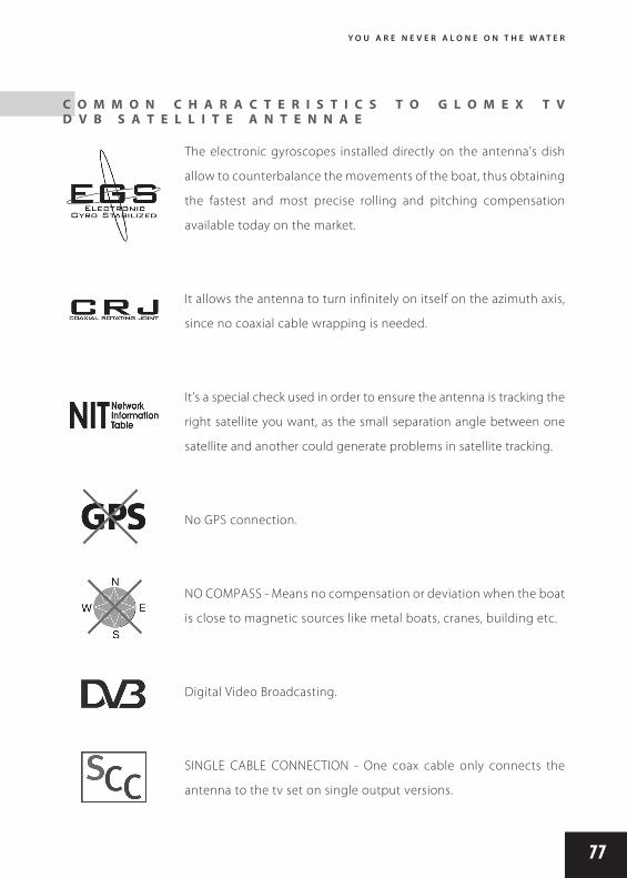
77
Y O U A R E N E V E R A L O N E O N T H E W A T E R
C O M M O N C H A R A C T E R I S T I C S T O G L O M E X T V D V B S A T E L L I T E A N T E N N A E
The electronic gyroscopes installed directly on the antenna’s dish
allow to counterbalance the movements of the boat, thus obtaining
the fastest and most precise rolling and pitching compensation
available today on the market.
It allows the antenna to turn infinitely on itself on the azimuth axis,
since no coaxial cable wrapping is needed.
It’s a special check used in order to ensure the antenna is tracking the
right satellite you want, as the small separation angle between one
satellite and another could generate problems in satellite tracking.
No GPS connection.
NO COMPASS - Means no compensation or deviation when the boat
is close to magnetic sources like metal boats, cranes, building etc.
Digital Video Broadcasting.
SINGLE CABLE CONNECTION - One coax cable only connects the
antenna to the tv set on single output versions.

78
As we have previously mentioned, Glomex has always studied the problem of the recep-
tion of TV signals on board moving vehicles very closely, be it a recreational vehicle or
a vessel. Naturally, the broadcast of terrestrial TV has always concerned the Company,
which has followed up on the developments up to the emergence of the digital ter-
restrial, DVBT, which translates into digital video broadcasting terrestrial. For analogue
signal, the problems that need solving are always linked to targeting, even if, in this case,
it is about targeting towards terrestrial radio stations and not towards a satellite.
Omni directional systems have appeared with time; these have also given satisfactory
results, yet for Glomex, satisfactory does not mean optimal and, thus, research has never
gone interrupted. Inevitably for Glomex, the digital terrestrial will also dock to moving
antennae systems, which is something particularly refined in the technological field. Cur-
rently, the broadcast of terrestrial TV signals is still analogue and digital, thus, Glomex
proposes systems capable of guaranteeing the reception of both signals, despite the fact
the analogue is destined to disappear.
The characteristic of digital signals is that of being qualitatively superior due to technical
reasons which we will not delay in explaining, yet, conversely, it also implies a strong apa-
thy for weak signals, which inevitably translates into loss of information. Being aware of
this, Glomex has studied highly efficient systems, capable not only of orientation towards
the broadcasting radio station efficiently and continuously, but also of not undergoing
loss of information due to weak signals or saturation with very strong signals.
All of this has been possible by combining high performance receiving elements with
electronic equipment capable of managing this performance in order to always offer a
clean and qualitatively appropriate signal to the receiver. The combination of directive
receiving elements with Omni directional elements, positioned at different levels, that
is, a vertically polarized element and another horizontally polarized element, guarantees
A L W A Y S T V , B U T L A N D - B A S E D A N D D I G I T A L

79
Y O U A R E N E V E R A L O N E O N T H E W A T E R
signal capture even under difficult conditions. The downstream plant, made up of an am-
plifier capable of emphasizing the signal without making noise, does the rest when the
signals are weak. When the signals are strong, the same circuit endowed by By-Pass lets
them reach the receiver in the same way as they are received. The management of the
antenna’s positioning is very simple, inasmuch as the control unit is easy to figure out and
it also allows to rapidly seeing when the received signal is “good”, thus, this is when the
moment of stopping our antenna has arrived and we can enjoy the show.
Among Glomex intended for terrestrial TV, those technologically advanced and capable
to offer such performance in order to always ensure the viewing of your favourite TV
show, we find Polaris V9130.
In short, it is a simple receiving system, efficient and comfortable to use with the remote
control included, which gives you the possibility of managing the system while being
comfortably seated.
With this antenna, there will not be any award shows or matches that you cannot watch
because you have chosen to take a trip by boat or on a recreational vehicle.
We are only left to conclude our tour into the fascinating world of telecommunications at
sea hoping to having offered everyone exhaustive and, above all, simple answers.
We have made our best effort not to go deep into arguments of a technical nature, we
must say, without great effort, that the rest of this book is not a technical manual, but a
simple guide for everyone. With the awareness of having bored many already close to the
topic, we hope to have soothed any doubts or, at least, helped in the understanding of
phenomena behind transmissions at sea to all others.

80
GLOMEX srl ©September 2008
Free copy
Graphic project
Massimiliano Montanari
Paola Roberto
MDM Forlì
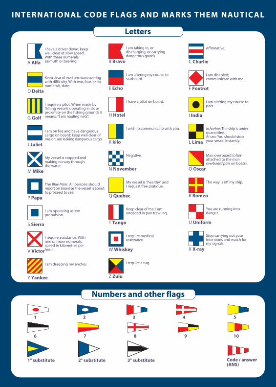
YOU ARE NEVER ALONE ON THE WATER is a text written
to help anyone to understand the phenomena on which
radio is based, the same that determine the quality of
communications with VHF and TV reception on board a
mobile means of transportation. We have also inserted a
lot of information regarding security at sea, in order to of-
fer a tool to be kept on board permanently, finding basic
radio-technical elements as well as general-purpose infor-
mation for navigators. Our main effort is to show things in
a simple manner, to allow anyone to understand technical
topics which people are often not aware of due to their
complexity. Naturally we are targeting a broad audience,
composed mainly of people who have never had a way to
become familiar with the subject. YOU ARE NEVER ALONE
ON THE WATER: we designed it to be on board during the
trip, which is the reason for this format. However, reading
it before sailing is useful in our opinion, since it also inclu-
des many practical safety topics.
Angelo Colombo - Piero Baldassarri
Free copy