Embed Size (px)
Citation preview
Load-induced oriented damage and anisotropyof rock-like materials
Andrzej Litewkaa,*, Janusz Debinskib,1
aDepartamento da Engenharia Civil, Universidade da Beira Interior,
Calcada Fonte do Lameiro, 6200-358 Covilha, PortugalbInstitute of Structural Engineering, Poznan University of Technology, ul. Piotrowo 5, 60-965 Poznan, Poland
Received in revised form 6 April 2003
Abstract
Theoretical model for deformability of brittle rock-like materials in the presence of anoriented damage of their internal structure is formulated and verified experimentally. This
model is based on the assumption that non-linearity of the stress–strain curves of these mate-rials is a result of irreversible process of oriented damage growth. It was also assumed that amaterial response, represented by the strain tensor, is a function of two tensorial variables: the
stress tensor and the damage effect tensor that is responsible for the current state of the internalstructure of the material. The explicit form of the respective non-linear stress–strain relationsthat account for the appropriate damage evolution equation was obtained by employing the
theory of tensor function representations and by using the results of own experiments ondamage growth. Such an oriented damage that grows in the material, described by the secondorder symmetric damage effect tensor, results in gradual development of the material aniso-tropy. The validity of the constitutive equations proposed was verified by using the available
experimental results for concrete subjected to the plane state of stress. The relevant experi-mental data for sandstone and concrete subjected to tri-axial state of stress were also used.# 2003 Elsevier Ltd. All rights reserved.
Keywords: Anisotropic damage; Brittle solids; Deformation-Induced anisotropy; Constitutive behaviour
1. Introduction
Increasing requirements of safety and reliability imposed on engineeringstructures give rise to deeper studies of mechanical properties of materials and
International Journal of Plasticity 19 (2003) 2171–2191
www.elsevier.com/locate/ijplas
0749-6419/03/$ - see front matter # 2003 Elsevier Ltd. All rights reserved.
doi:10.1016/S0749-6419(03)00064-0
* Corresponding author. Tel.: +351-275-329704; fax: +351-275-319888.
E-mail addresses: [email protected] (A. Litewka); [email protected] (J. Debinski).1 Visiting Professor from Faculty of Architecture, Poznan University of Technology, ul. Strusia 12,
60-711 Poznan, Poland.
also to formulation of more precise theoretical models capable to describe pro-cesses observed in materials subjected to complex loading. Existing theoreticalmodels developed to describe mechanical behaviour of brittle materials like nat-ural rocks have been mainly based on semi-empirical description of availableexperimental results. More consistent mathematical models formulated for con-crete by Chen (1982) and Geniev et al. (1974) postulated plasticity of thismaterial. Such a description of mechanical response of material was sufficient toexplain its non-linear behaviour but was insufficient to account for simultaneousvariation of its internal structure. Such phenomenon of internal damage growthwas studied experimentally (Mitrofanov and Dovzenko, 1991, Bogucka et al.,1998; Litewka et al., 1999) and theoretically (Horii and Nemat-Nasser, 1983;Karpenko, 1987; Baikov, 1990; Basista, 2001). It was shown there that defor-mation of brittle rock-like materials and cementitious composites is accompaniedby development of oriented cracks and that an amount of this internal damageand also privileged directions of the crack arrangement are closely connectedwith the magnitude and directions of the principal stresses applied. That is why,more effective ways to formulate the constitutive equations for concrete and alsofor rocks seems to be that based on the methods of the damage mechanics which weresuccessfully used by Hayhurst (1983), Lemaitre (1984), Murakami (1987) and Kraj-cinovic (1995). Recently the damage mechanics is widely used in formulation ofnumerical and theoretical models that describe the behaviour of various materials(Brunig, 2002; Chiarelli et al., 2003; Gupta and Bergstrom, 2002; Mahnken, 2002;Stumpf and Saczuk, 2001; Taylor et al., 2002). Possible application of continuumdamage mechanics in a theoretical description of the mechanical behaviour of rock-like materials was anticipated in some earlier papers by Eimer (1971) and Dragon(1976) and was also discussed more recently by Chaboche et al. (1995). Furtherdevelopment of this approach due to Halm and Dragon (1996, 1998), Litewka et al.(1996) and Murakami and Kamiya (1997) resulted in formulation of the phenomen-ological models that could be used in some practical applications. Interesting gen-eralisations of theoretical models for multi-axial state of stress presented by Halm andDragon (1996, 1998) and Murakami and Kamiya (1997) cannot be considered as afinal solution of the problem. To obtain realistic theoretical description of overallmaterial response accounting for oriented damage growth and development ofdamage induced anisotropy the extensive experimental studies are needed. Someother theoretical models were formulated on the basis of micromechanics (Krajci-novic et al., 1991; Ju, 1991; Basista, 2001). However, these micromechanicallyinspired phenomenological models in their actual form were verified only for somespecific cases of loading. Potentialities of micromechanics in formulation of theore-tical models of material behaviour are also shown in some recent papers by Bruzzi etal. (2001), Chaboche et al. (2001) and Paquin et al. (2001).The authors of this note presented in their earlier paper the constitutive equations
for concrete subjected to bi-axial state of stress (Litewka and Debinski, 1997). Thatmathematical model was formulated by employing the methods of continuumdamage mechanics and also those of the theory of tensor function representations(Spencer, 1971; Boehler, 1987; Betten, 1998). The aim of this paper is to present
2172 A. Litewka, J. Debinski / International Journal of Plasticity 19 (2003) 2171–2191
more general theoretical model capable to describe mechanical behaviour of initiallyisotropic brittle rock-like materials subjected to tri-axial state of stress. The physicalbackground for this theoretical description was supplied by own experimental studiesof oriented damage growth performed for concrete (Bogucka et al., 1998; Litewka etal., 1999). More recent experimental data on this subject are presented in Appendix A.Validity of constitutive equations proposed was verified by using the availableexperimental data for concrete and sandstone subjected to multi-axial state of stress.
2. Theoretical model
It is known from theoretical and experimental studies by Chen (1982), Horii andNemat-Nasser (1983), Mitrofanov and Dovzenko (1991) and Bogucka et al. (1998)that load applied to brittle rock-like materials results in the development of orientedmicrocracks perpendicular to the direction of maximum principal stress. It meansthat an originally isotropic material becomes orthotropic one with principal axes oforthotropy coinciding with the directions of the principal stresses. According to therules of the continuum damage mechanics the current state of the deterioratedmaterial structure can be described by certain independent variable or group ofvariables (Onat and Leckie, 1988) responsible for the current state of the materialstructure. Mathematical model for deformability of brittle rock-like materials pro-posed in this paper is based on the assumption of tensorial nature of the materialdamage (Leckie and Onat, 1981). That is why the symmetric second rank damagetensor defined by Murakami and Ohno (1981) and Betten (1983) was used as a vari-able responsible for deterioration of the material internal structure. Explicit form ofthe relevant constitutive equations was found by employing the methods of the theoryof tensor function representations as applied to solid mechanics by Rivlin and Ericsen(1955), Boehler (1987) and Betten (1998). Preliminary results of possible applicationof the above theories to describe a non-linear behaviour of a concrete subjected touni-axial state of stress, including the experimental verification, was explained else-where (Litewka et al., 1996). The generalisation of those constitutive equations to bepresented here consists of the stress strain relations for anisotropic elastic solids
"ij ¼ Aijkl�kl ð1Þ
where "ij is the strain tensor and �kl is the stress tensor. The fourth order tensor Aijkl
that appears in Eq. (1) is a function of the damage effect tensor Dij (Litewka, 1985,1989) and defines the material constants of an orthotropically damaged solid. It wasshown earlier (Litewka et al., 1996) that instead of the most general representationof such a tensor function presented Rivlin and Ericsen (1955) the following line-arised form seems to be sufficient
Aijkl ¼ ��0E0
�ij�kl þ1þ �02E0
�ik�jl þ �il�jk� �
þ
þ C �ijDkl þDij�kl� �
þD �ikDjl þ �jlDik þ �ilDjk þ �jkDil
� �: ð2Þ
A. Litewka, J. Debinski / International Journal of Plasticity 19 (2003) 2171–2191 2173
e above equation contains the Kronecker delta �ij, the Young modulus E0 and
ThPoisson ratio �0 for an originally undamaged material, two constants C and D to bedetermined experimentally and the second order symmetric damage effect tensor Dijresponsible for the current state of internal structure of the material. SubstitutingEq. (2) to the stress–strain relation (1) the following tensor function was obtained
2174 A. Litewka, J. Debinski / International Journal of Plasticity 19 (2003) 2171–2191
"ij ¼ ��0E0
�ij�kk þ1þ �0E0
�ij þ C �ijDkl�kl þDij�kk� �
þ 2D �ikDkj þDik�kj� �
ð3Þ
which describes the anisotropic elastic response of the damaged material.Deterioration of the material structure due to applied load can be described by the
damage evolution equation expressed in the form of the tensor function
Oij ¼ f1�ij þ f2�ij þ f3�ik�kj; ð4Þ
where Oij is a classical second order damage tensor formulated by Vakulenko andKachanov (1971), Murakami and Ohno (1981) and Betten (1983) which is defined asa generalisation of the scalar damage parameter (Kachanov, 1958). The ownexperiments of the authors (Bogucka et al., 1998; Litewka et al., 1999) show that theprocess of the damage growth starts at the very beginning of the loading. That iswhy it seems to be reasonable to look for the damage evolution equation in thisspecific class of tensor function representation expressed by Eq. (4) where damagetensor depends directly on the stresses applied. Eq. (4) contains three multipliers f1,f2 and f3 that are scalar-valued functions of the stress tensor invariants. To deter-mine the explicit form of these multipliers, what is necessary to describe the beha-viour of the material subjected to tri-axial state of stress, the analysis ofmathematical properties of the Eq. (4) was performed. Preliminary experimentalverification of possible shapes of this equation, by employing the available experi-mental results for uni-axial and bi-axial compression for several types of concrete,was also done (Litewka et al., 1996, 1999, Litewka and Debinski, 1997). It wasfound that those results needed some generalisation in the case of the tri-axial stateof stress, and it was finally found that the respective scalar functions contained inEq. (4) should have the following form
f1 ¼ Asklskl 1þHdet�pq� �F
f2 ¼ Bffiffiffiffiffiffiffiffiffiffiffi�kl�kl
p1þHdet�pq� �F
f3 ¼ 0; ð5Þ
where skl is the stress deviator and A, B, F are unknown material parameters to bedetermined experimentally. The multiplier H is a certain function of the actual stateof stress and determination of its specific form requires the separate analysis pre-sented at the end of this chapter. Taking into account the relations expressed in Eqs.(5) the damage evolution Eq. (4) can be written in the following form
Oij ¼ Asklskl 1þHdet�pq� �F
�ij þ Bffiffiffiffiffiffiffiffiffiffiffi�kl�kl
p1þHdet�pq� �F
�ij: ð6Þ
The first term of Eq. (6) represents the isotropic damage and the second oneaccounts for the oriented damage due to different effects of the stress tensor
components. For example, compressive principal components of the stress tensorreduce amount of the damage on the respective planes, whereas the tensile normalstresses increase corresponding components of the damage tensor.The damage tensor Oij, whose components are ranging from zero for the material
in its original undamaged state to unity in the case of a fully damaged solid thatlooses its continuity, is very useful to describe the continuity of the material only. Aswas shown earlier by Murakami and Ohno (1981) and Litewka (1985, 1989) such adamage tensor is not sufficient to describe the strength and stiffness reduction of thedamaged material, and that is why it was necessary to define a new second orderdamage effect tensor Dij. The relation
Di ¼Oi
1� Oi; i ¼ 1; 2; 3 ð7Þ
between the principal values O1, O2 and O3 of the damage tensor Oij and the principalcomponents D1, D2 and D3 of the damage effect tensor Dij contained in Eqs. (2) and(3) was formulated by Litewka (1985). The principal components of the damage effecttensor calculated from Eq. (7) are ranging from zero for an undamaged material toinfinity for a fully damaged material, which means that increasing damage expressedin terms of the damage effect tensor gradually reduces the stiffness of the material tozero. Taking into account Eqs. (6) and (7) the stress–strain relations described by Eq.(1) or (3) become non-linear functions of the stress tensor components only. Theseequations reduce to well known stress–strain relations for an isotropic elastic solid inthe case of undamaged material, where Oij=0 and Dij=0.According to the theoretical model proposed, the non-linearity of the respective
stress–strain curves is considered as a result of irreversible processes of orientedmaterial damage growth, discussed in Appendix A, that eventually leads to materialfailure. In such a situation the limit of validity of the model proposed is determinedby the limit of applicability of continuum damage mechanics. Thus, the stress–strainrelations proposed here can be used to describe mechanical behaviour of brittlerock-like materials for loads increasing from zero up to the maximum value thatcorresponds to the strength of the material for a given state of stress. It means thatthe theoretical model proposed describes the main part of the stress–strain curves,whereas the post-failure material behaviour associated usually with softening of thesolid is excluded from the analysis presented here. In the specific case of uni-axialcompression the limit of applicability of continuum damage mechanics is deter-mined by the compressive strength of the material fc and that is why the stress–strainrelations presented here cease to be valid, if the compressive stress reaches this value.Relevant experiments show that continuity of the material subjected to axial com-pressive load is lost when the compressive strength of the material fc is achieved andthen the specimen tested breaks into irregular particles of different size. The currentstate of such a broken material cannot be described by using the methods of con-tinuum damage mechanics and a more appropriate formulation would be onedeveloped for granular media. The problem of limitation of applicability of thedamage mechanics to the peak stress was studied by Basista (2001) by using themethods of micromechanics.
A. Litewka, J. Debinski / International Journal of Plasticity 19 (2003) 2171–2191 2175
Eqs. (2), (3) and (6) contain five constants A, B, C, D and F to be determinedexperimentally. The various methods used to identify four of these constants thatappear in the case of bi-axial state of stress, namely A, B, C and D, were presentedby the authors in their earlier papers (Litewka et al., 1996, 1999; Bogucka et al.,1998). Those methods are based on relevant experimental data for uni-axial or bi-axial compression of concrete and the final form of the equations used to calculatethese constants and other details related to the numerical procedure can be foundelsewhere (Litewka et al., 1999). The specific method of identification of the con-stants A, B, C and D adopted in this paper is presented in Appendix B.Here the attention in focused mainly on fifth constant F and on function H that
appear only for three-dimensional states of stress. The constant F can be calculateddirectly by using the experimental results for tri-axial state of stress, but the form ofthe function H could be determined from the analysis of the specific case of hydro-static pressure expressed by the stress tensor
�ij ¼ p�ij; ð8Þ
where p=�ph is the value of hydrostatic pressure. According to the experimentalresults obtained for concrete and for some rocks subjected to hydrostatic pressure(Chen, 1982; Carvalho et al., 1997) the relation between applied pressure and rele-vant deformation is linear. It means that in this specific case of loading the damagetensor components calculated from Eq. (6) should be equal to zero. Substituting (8)to (6) and taking into account that Oij=0 one can obtain the relation
H ¼1
p3h¼
1
�extrj j3ð9Þ
where �extr is an extreme value of the principal stresses applied. For H determined byEq. (9) no damage growth occurs in the case of hydrostatic compression. On the otherhand, it can be shown that for tri-axial uniform tension considerable amount of iso-tropic material damage is obtained from the damage evolution Eq. (6) for relativelysmall stress applied. This high rate of damage growth results in much lower tensilestrength of brittle materials compared to that observed for compression.The equations presented in this paper were formulated in such a form that is
necessary to describe the available experimental data for brittle rock-like materials.Analysis of the experimental results presented by Kupfer (1973), Ehm and Schneider(1985), Thienel et al. (1991), Ligeza (1999), Rummel (1972), Green and Swanson(1973) and Yazdani and Karnavat (1996) show that only monotonic loading isanalysed there. That is why the explicit form of the equations shown here corre-sponds to this case of loading. All the generalizations of these equations forunloading, cycling loading and non-proportional loading are possible but are lim-ited by the shortage of relevant experimental data necessary to explain the nature ofthe specific physical problems. Some recent experimental data on oriented damagegrowth obtained by the authors for loading, unloading and subsequent loading foruni-axial compression are discussed in Appendix A. Possible generalization of theconclusions presented there for cycling loading under multi-axial state of stressrequires further experimental studies.
2176 A. Litewka, J. Debinski / International Journal of Plasticity 19 (2003) 2171–2191
3. Bi-axial state of stress
Available experimental data on mechanical behaviour of brittle rock-like mate-rials concern mainly to concrete subjected to the plane state of stress (Kupfer,1973; Ehm and Schneider, 1985; Thienel et al., 1991; Ligeza, 1999). Preliminaryexperimental verification of the theoretical model, performed by the authors of thisnote in their earlier paper (Litewka and Debinski, 1997), was based on someexperimental data presented by Thienel et al. (1991). More complete experimentalverification showed here was done by using the respective data collected by Kupfer(1973). The theoretical predictions presented in this paper are based on the stress–strain relation for damaged solid (3) specified for the plane state of stress definedby the principal stresses �1=0 and �2 > �3 6¼ 0. Substituting these stress tensorcomponents to Eq. (3) and taking into account (6) and (7) the following relationswere obtained
"1 ¼ ��0E0
kþ 1ð Þ�3 þ C
2
3A k2 � kþ 1� �
k�33 þ sign �3ð ÞB
ffiffiffiffiffiffiffiffiffiffiffiffiffik2 þ 1
pk2�3
3
1�2
3A k2 � kþ 1� �
�23 � sign �3ð ÞB
ffiffiffiffiffiffiffiffiffiffiffiffiffik2 þ 1
pk�2
3
264 þ
2
3A k2 � kþ 1� �
�33 þ sign �3ð ÞB
ffiffiffiffiffiffiffiffiffiffiffiffiffik2 þ 1
p�33
1�2
3A k2 � kþ 1� �
�23 � sign �3ð ÞB
ffiffiffiffiffiffiffiffiffiffiffiffiffik2 þ 1
p�23
þ
2
3A k2 � kþ 1� �
kþ 1ð Þ�33
1�2
3A k2 � kþ 1� �
�23
375
ð10Þ
"2 ¼k� �0E0
�3 þ C 2kþ 1ð Þ
2
3A k2 � kþ 1� �
�33 þ sign �3ð ÞB
ffiffiffiffiffiffiffiffiffiffiffiffiffik2 þ 1
pk�3
3
1�2
3A k2 � kþ 1� �
�23 � sign �3ð ÞB
ffiffiffiffiffiffiffiffiffiffiffiffiffik2 þ 1
pk�2
3
þ
264
þ
2
3A k2 � kþ 1� �
�33 þ sign �3ð ÞB
ffiffiffiffiffiffiffiffiffiffiffiffiffik2 þ 1
p�33
1�2
3A k2 � kþ 1� �
�23 � sign �3ð ÞB
ffiffiffiffiffiffiffiffiffiffiffiffiffik2 þ 1
p�23
375þ
þ 4D
2
3A k2 � kþ 1� �
k�33 þ sign �3ð ÞB
ffiffiffiffiffiffiffiffiffiffiffiffiffik2 þ 1
pk2�3
3
1�2
3A k2 � kþ 1� �
�23 � sign �3ð ÞB
ffiffiffiffiffiffiffiffiffiffiffiffiffik2 þ 1
pk�2
3
ð11Þ
A. Litewka, J. Debinski / International Journal of Plasticity 19 (2003) 2171–2191 2177
� � ffiffiffiffiffiffiffiffiffiffiffiffiffip2
"3 ¼1� �0k
E0�3 þ C
2
3A k2 � kþ 1 k�3
3 þ sign �3ð ÞB k2 þ 1k2�33
1�2
3A k2 � kþ 1� �
�23 � sign �3ð ÞB
ffiffiffiffiffiffiffiffiffiffiffiffiffik2 þ 1
pk�2
3
þ64
þ kþ 2ð Þ
2
3A k2 � kþ 1� �
�33 þ sign �3ð ÞB
ffiffiffiffiffiffiffiffiffiffiffiffiffik2 þ 1
p�33
1�2
3A k2 � kþ 1� �
�23 � sign �3ð ÞB
ffiffiffiffiffiffiffiffiffiffiffiffiffik2 þ 1
p�23
375þ
þ 4D
2
3A k2 � kþ 1� �
�33 þ sign �3ð ÞB
ffiffiffiffiffiffiffiffiffiffiffiffiffik2 þ 1
p�33
1�2
3A k2 � kþ 1� �
�23 � sign �3ð ÞB
ffiffiffiffiffiffiffiffiffiffiffiffiffik2 þ 1
pk�2
3
ð12Þ
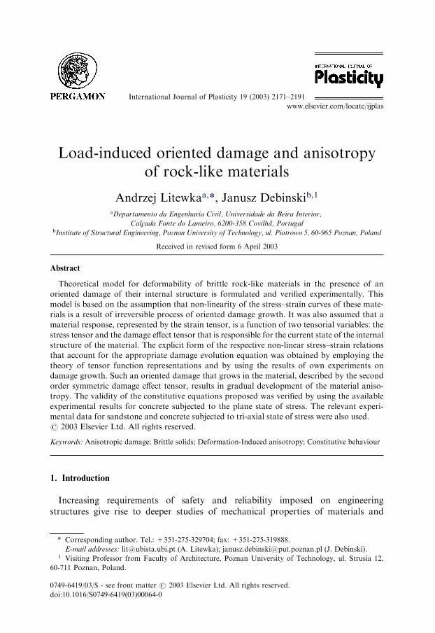
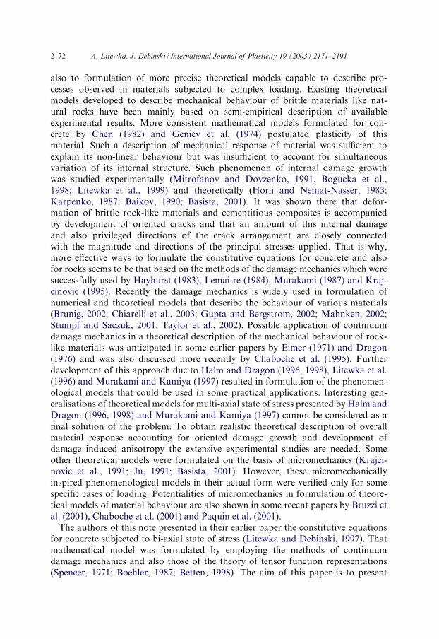
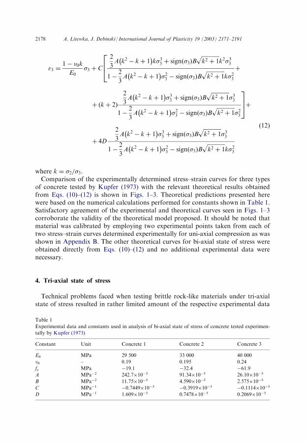
where k ¼ �2=�3.Comparison of the experimentally determined stress–strain curves for three types
of concrete tested by Kupfer (1973) with the relevant theoretical results obtainedfrom Eqs. (10)–(12) is shown in Figs. 1–3. Theoretical predictions presented herewere based on the numerical calculations performed for constants shown in Table 1.Satisfactory agreement of the experimental and theoretical curves seen in Figs. 1–3corroborate the validity of the theoretical model proposed. It should be noted thatmaterial was calibrated by employing two experimental points taken from each oftwo stress–strain curves determined experimentally for uni-axial compression as wasshown in Appendix B. The other theoretical curves for bi-axial state of stress wereobtained directly from Eqs. (10)–(12) and no additional experimental data werenecessary.
4. Tri-axial state of stress
Technical problems faced when testing brittle rock-like materials under tri-axialstate of stress resulted in rather limited amount of the respective experimental data
Table 1
Experimental data and constants used in analysis of bi-axial state of stress of concrete tested experimen-
tally by Kupfer (1973)
Constant
Unit Concrete 1 Concrete 2 Concrete 3E0
MPa 29 500 33 000 40 000�0
– 0.19 0.195 0.24fc
MPa �19.1 �32.4 �61.9A
MPa�2 242.710�5 91.3410�5 26.1010�5B
MPa�2 11.7510�5 4.59010�5 2.57510�5C
MPa�1 �0.744910�5 �0.391910�5 �0.111410�5D
MPa�1 1.60910�5 0.747810�5 0.206910�52178 A. Litewka, J. Debinski / International Journal of Plasticity 19 (2003) 2171–2191
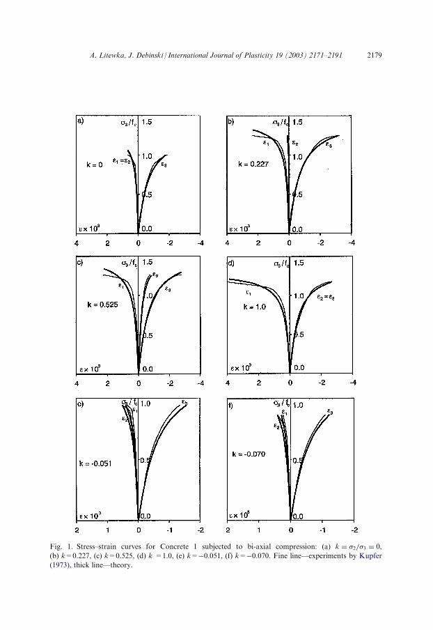
Fig. 1. Stress–strain curves for Concrete 1 subjected to bi-axial compression: (a) k ¼ �2=�3 ¼ 0,
(b) k=0.227, (c) k=0.525, (d) k =1.0, (e) k=�0.051, (f) k=�0.070. Fine line—experiments by Kupfer
(1973), thick line—theory.
A. Litewka, J. Debinski / International Journal of Plasticity 19 (2003) 2171–2191 2179
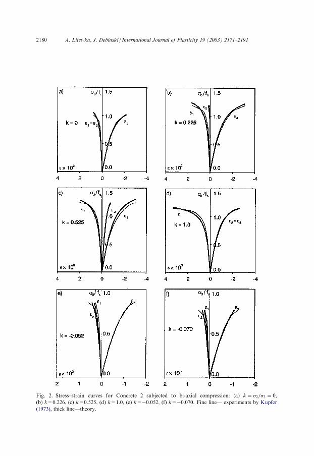
Fig. 2. Stress–strain curves for Concrete 2 subjected to bi-axial compression: (a) k ¼ �2=�3 ¼ 0,
(b) k=0.226, (c) k=0.525, (d) k=1.0, (e) k=�0.052, (f) k=�0.070. Fine line— experiments by Kupfer
(1973), thick line—theory.
2180 A. Litewka, J. Debinski / International Journal of Plasticity 19 (2003) 2171–2191
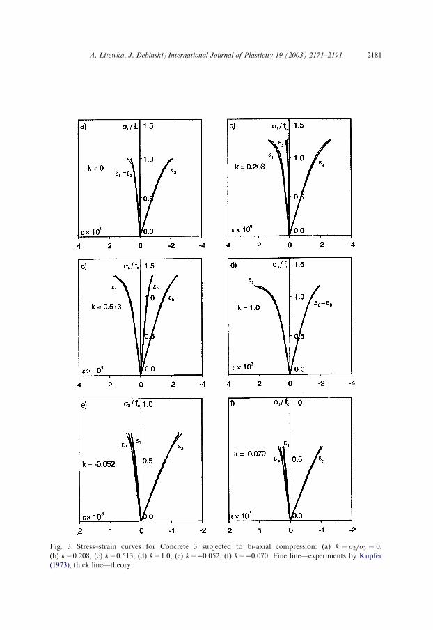
Fig. 3. Stress–strain curves for Concrete 3 subjected to bi-axial compression: (a) k ¼ �2=�3 ¼ 0,
(b) k=0.208, (c) k=0.513, (d) k=1.0, (e) k=�0.052, (f) k=�0.070. Fine line—experiments by Kupfer
(1973), thick line—theory.
A. Litewka, J. Debinski / International Journal of Plasticity 19 (2003) 2171–2191 2181
on the mechanical behaviour of rocks and concrete. Some experimental resultsobtained for rocks subjected to simultaneous action of axial compressive loadrepresented by compressive stress �33 and hydrostatic pressure p=�ph, referred toas a confining pressure, can be found in monographs on rock mechanics by Cris-tescu and Hunsche (1998), Derski et al. (1989) and Goodman (1989). These data andsimilar results available for concrete (Chen, 1982; Neville, 1995) make it possible toconclude that hydrostatic pressure increases the axial load that can be sustained.That is why with high lateral compressive stress, extremely high strengths of rock-like materials have been recorded (Neville, 1995). Moreover, in the limit case ofhydrostatic pressure, practically linear mechanical response of a material, describedby the law of elastic change of volume, is obtained (Carvalho et al., 1997). It meansthat confining pressure reduces the amount of the internal damage accumulated inthe material in the loading process and for hydrostatic pressure practically nodamage growth is observed.To present the potentialities of the theoretical model proposed, the stress–strain
relation (3) and the damage evolution Eq. (6) were expressed in terms of the com-ponents of the following stress tensor
�ij ¼�1 ¼ p 0 0
0 �2 ¼ p 00 0 �3 ¼ �33 þ p
24
35 ð13Þ
which corresponds to axial compression combined with confining pressure. Sub-stituting the components of the stress tensor (13) to the damage evolution Eq. (6)and taking into account (9) the following principal components of the damage ten-sor were obtained
O1 ¼ O2 ¼2
3A�2
33 þ Bpffiffiffiffiffiffiffiffiffiffiffiffiffiffiffiffiffiffiffiffiffiffiffiffiffiffiffiffiffiffiffiffiffiffiffiffi�233 þ 2�33pþ 3p2
q� 1þ
�33 þ pð Þp2
�33 þ 3pð Þ3
�� ��" #F
ð14Þ
O3 ¼2
3A�2
33 þ B �33 þ pð Þ
ffiffiffiffiffiffiffiffiffiffiffiffiffiffiffiffiffiffiffiffiffiffiffiffiffiffiffiffiffiffiffiffiffiffiffiffi�233 þ 2�33pþ 3p2
q� 1þ
�33 þ pð Þp2
�33 þ 3pð Þ3
�� ��" #F
; ð15Þ
where F is a constant to be determined experimentally. The stress–strain relation (3)specified for the stress tensor (13) makes it possible to determine the followingprincipal values of the strain tensor
"1 ¼ "2
¼ ��0E0
�33 þ1� 2�0
E0pþ C D1 þD3ð Þ�33 þ p 5D1 þD3ð Þ½ � þ 4DpD1 ð16Þ
2182 A. Litewka, J. Debinski / International Journal of Plasticity 19 (2003) 2171–2191
"3 ¼�33E0
þ1� 2�0
E0pþ C 2D3�33 þ p 2D1 þ 4D3ð Þ½ � þ 4D �33 þ pð ÞD3: ð17Þ
The principal components of the damage effect tensor D1=D2 and D3 included inEqs. (16) and (17) are defined by relation (7).The validity of Eqs. (14)–(17) was verified experimentally by employing the stress–
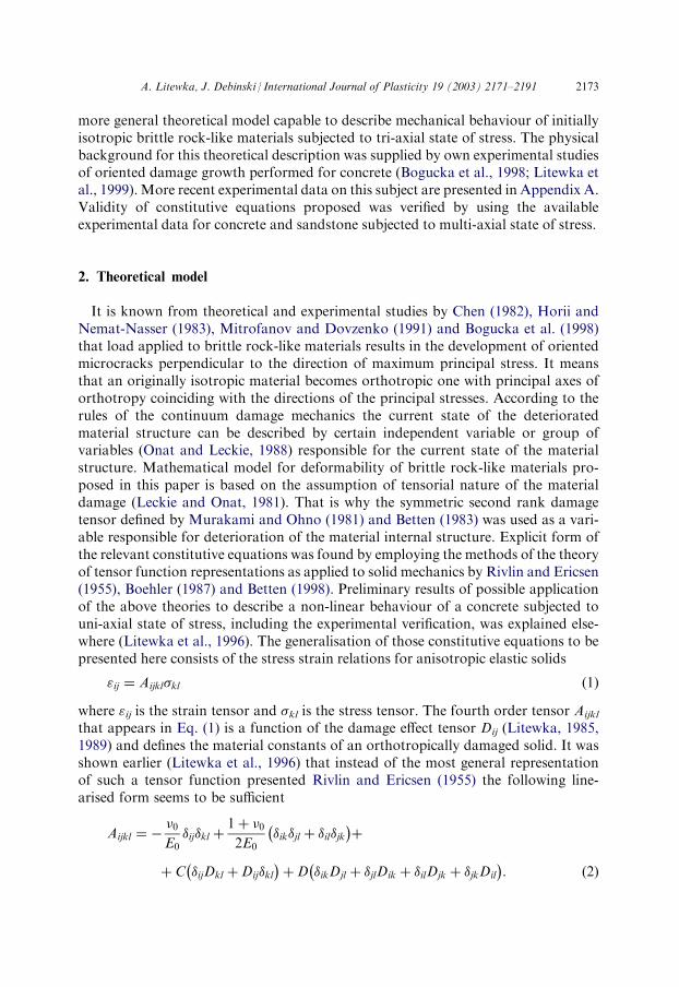
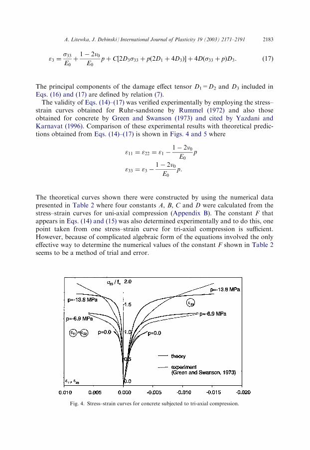
strain curves obtained for Ruhr-sandstone by Rummel (1972) and also thoseobtained for concrete by Green and Swanson (1973) and cited by Yazdani andKarnavat (1996). Comparison of these experimental results with theoretical predic-tions obtained from Eqs. (14)–(17) is shown in Figs. 4 and 5 where
"11 ¼ "22 ¼ "1 �1� 2�0
E0p
"33 ¼ "3 �1� 2�0
E0p:
The theoretical curves shown there were constructed by using the numerical datapresented in Table 2 where four constants A, B, C and D were calculated from thestress–strain curves for uni-axial compression (Appendix B). The constant F thatappears in Eqs. (14) and (15) was also determined experimentally and to do this, onepoint taken from one stress–strain curve for tri-axial compression is sufficient.However, because of complicated algebraic form of the equations involved the onlyeffective way to determine the numerical values of the constant F shown in Table 2seems to be a method of trial and error.
Fig. 4. Stress–strain curves for concrete subjected to tri-axial compression.
A. Litewka, J. Debinski / International Journal of Plasticity 19 (2003) 2171–2191 2183
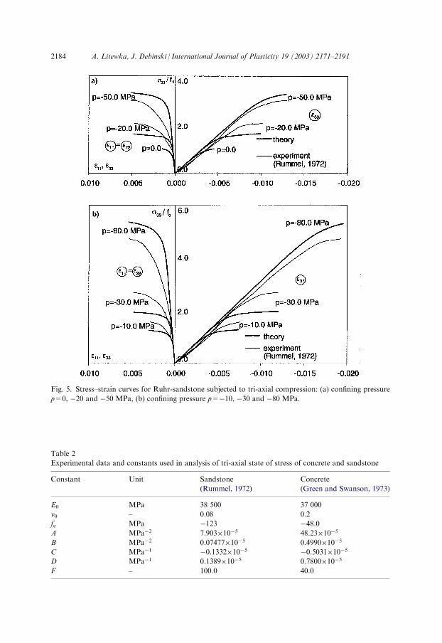
Fig. 5. Stress–strain curves for Ruhr-sandstone subjected to tri-axial compression: (a) confining pressure
p=0, �20 and �50 MPa, (b) confining pressure p=�10, �30 and �80 MPa.
Table 2
Experimental data and constants used in analysis of tri-axial state of stress of concrete and sandstone
Constant
Unit Sandstone(Rummel, 1972)
Concrete
(Green and Swanson, 1973)
E0
MPa 38 500 37 000�0
– 0.08 0.2fc
MPa �123 �48.0A
MPa�2 7.90310�5 48.2310�5B
MPa�2 0.0747710�5 0.499010�5C
MPa�1 �0.133210�5 �0.503110�5D
MPa�1 0.138910�5 0.780010�5F
– 100.0 40.02184 A. Litewka, J. Debinski / International Journal of Plasticity 19 (2003) 2171–2191
The agreement of experimental data with the theoretical predictions seen in Figs. 4and 5 is less satisfactory than that obtained for bi-axial loading. However, suchbigger difference could be acceptable taking into account much larger scatter ofexperimental results for concrete and rocks tested under tri-axial state of stress.
5. Conclusions
Application of methods of continuum damage mechanics combined with the the-ory of tensor function representations made it possible to formulate theoreticalmodel capable to describe mechanical behaviour of initially isotropic brittle rock-like materials. Experimental verification of the theoretical model proposed wasobtained by employing available experimental data for sandstone and for varioustypes of concrete subjected to multi-axial state of stress. It was found that theore-tical stress–strain curves for bi-axial and tri-axial loading obtained from the relevantequations presented in this paper show satisfactory agreement with experimentaldata.Increasing compressive strength of brittle rock-like materials detected experimen-
tally for specimens subjected to confining pressure can also be explained theoreti-cally within the mathematical model proposed. It means that the availableexperimental data corroborate the validity of the assumption that non-linearmechanical response of rock-like materials is a result of overall stiffness reductiondue to oriented damage growth. This irreversible process associated with develop-ment of material anisotropy and decrease of respective material constants can beconsidered as a macroscopic effect of deterioration of the material structure due toload applied.The theory presented in this paper was formulated in such a form that is necessary
to describe the available experimental data for brittle rock-like materials. That iswhy the explicit form of the equations shown here corresponds to monotonic tri-axial loading. Possible generalizations of these equations for unloading, cyclingloading and non-proportional loading are possible but are limited by the shortage ofrelevant experimental data necessary to explain the nature of the specific physicalprocesses of damage growth and to perform the realistic experimental verification.
Acknowledgements
This work was done within the F.C.T. Programme ‘‘Fin. Plurianual-C.E.C.U.B.I.’’ and P.U.T. Programme 11-1654/BW-2002.
Appendix A. Experiments on damage growth for cycling loading
The authors of this note performed the experiments to study the damage growthfor ordinary concrete C20 subjected to monotonic loading (four specimens) and also
A. Litewka, J. Debinski / International Journal of Plasticity 19 (2003) 2171–2191 2185
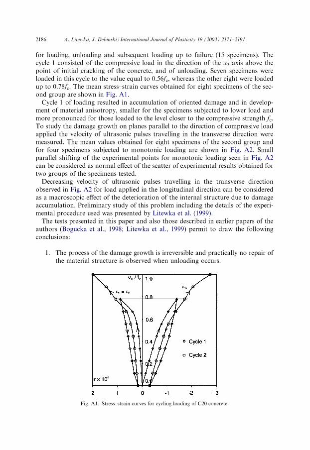
for loading, unloading and subsequent loading up to failure (15 specimens). Thecycle 1 consisted of the compressive load in the direction of the x3 axis above thepoint of initial cracking of the concrete, and of unloading. Seven specimens wereloaded in this cycle to the value equal to 0.56fc, whereas the other eight were loadedup to 0.78fc. The mean stress–strain curves obtained for eight specimens of the sec-ond group are shown in Fig. A1.Cycle 1 of loading resulted in accumulation of oriented damage and in develop-
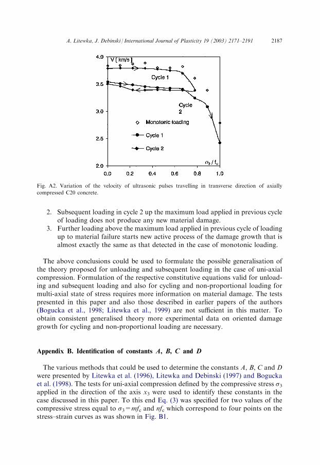
ment of material anisotropy, smaller for the specimens subjected to lower load andmore pronounced for those loaded to the level closer to the compressive strength fc.To study the damage growth on planes parallel to the direction of compressive loadapplied the velocity of ultrasonic pulses travelling in the transverse direction weremeasured. The mean values obtained for eight specimens of the second group andfor four specimens subjected to monotonic loading are shown in Fig. A2. Smallparallel shifting of the experimental points for monotonic loading seen in Fig. A2can be considered as normal effect of the scatter of experimental results obtained fortwo groups of the specimens tested.Decreasing velocity of ultrasonic pulses travelling in the transverse direction
observed in Fig. A2 for load applied in the longitudinal direction can be consideredas a macroscopic effect of the deterioration of the internal structure due to damageaccumulation. Preliminary study of this problem including the details of the experi-mental procedure used was presented by Litewka et al. (1999).The tests presented in this paper and also those described in earlier papers of the
authors (Bogucka et al., 1998; Litewka et al., 1999) permit to draw the followingconclusions:
1. The process of the damage growth is irreversible and practically no repair of
the material structure is observed when unloading occurs.Fig. A1. Stress–strain curves for cycling loading of C20 concrete.
2186 A. Litewka, J. Debinski / International Journal of Plasticity 19 (2003) 2171–2191
2. Subsequent loading in cycle 2 up the maximum load applied in previous cycle
of loading does not produce any new material damage.3. Further loading above the maximum load applied in previous cycle of loading
up to material failure starts new active process of the damage growth that isalmost exactly the same as that detected in the case of monotonic loading.The above conclusions could be used to formulate the possible generalisation ofthe theory proposed for unloading and subsequent loading in the case of uni-axialcompression. Formulation of the respective constitutive equations valid for unload-ing and subsequent loading and also for cycling and non-proportional loading formulti-axial state of stress requires more information on material damage. The testspresented in this paper and also those described in earlier papers of the authors(Bogucka et al., 1998; Litewka et al., 1999) are not sufficient in this matter. Toobtain consistent generalised theory more experimental data on oriented damagegrowth for cycling and non-proportional loading are necessary.
Appendix B. Identification of constants A, B, C and D
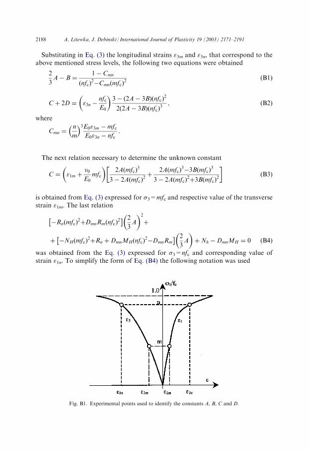
The various methods that could be used to determine the constants A, B, C and Dwere presented by Litewka et al. (1996), Litewka and Debinski (1997) and Boguckaet al. (1998). The tests for uni-axial compression defined by the compressive stress �3applied in the direction of the axis x3 were used to identify these constants in thecase discussed in this paper. To this end Eq. (3) was specified for two values of thecompressive stress equal to �3=mfc and nfc which correspond to four points on thestress–strain curves as was shown in Fig. B1.
Fig. A2. Variation of the velocity of ultrasonic pulses travelling in transverse direction of axially
compressed C20 concrete.
A. Litewka, J. Debinski / International Journal of Plasticity 19 (2003) 2171–2191 2187
Substituting in Eq. (3) the longitudinal strains "3m and "3n, that correspond to theabove mentioned stress levels, the following two equations were obtained
2
3A� B ¼
1� Cmn
nfcð Þ2�Cmn mfcð Þ
2ðB1Þ
Cþ 2D ¼ "3n �nfcE0
� 3� 2A� 3Bð Þ nfcð Þ
2
2 2A� 3Bð Þ nfcð Þ3
; ðB2Þ
where
Cmn ¼n
m
� �3E0"3m �mfcE0"3n � nfc
:
The next relation necessary to determine the unknown constant
C ¼ "1m þ�0E0
mfc
� 2A mfcð Þ
3
3� 2A mfcð Þ2þ
2A mfcð Þ3�3B mfcð Þ
3
3� 2A mfcð Þ2þ3B mfcð Þ
2
� �ðB3Þ
is obtained from Eq. (3) expressed for �3=mfc and respective value of the transversestrain "1m. The last relation
�Rn mfcð Þ2þDmnRm nfcð Þ
2� � 2
3A
� 2
þ
þ �NH mfcð Þ2þRn þDmnMH nfcð Þ
2�DmnRm
� � 2
3A
� þNh �DmnMH ¼ 0 ðB4Þ
obtained from the Eq. (3) expressed for �3=nfc and corresponding value of
wasstrain "1n. To simplify the form of Eq. (B4) the following notation was usedFig. B1. Experimental points used to identify the constants A, B, C and D.
2188 A. Litewka, J. Debinski / International Journal of Plasticity 19 (2003) 2171–2191
MH ¼
2
3A� B
� mfcð Þ
3
1�2
3A� B
� mfcð Þ
2
NH
Dmn
Rn
¼H nfcð Þ
3
1�H nfcð Þ2
¼
"1
"1
¼ nð
n þ�0E0
nfc
m þ�0E0
mfc
fcÞ3�
NH nfcð Þ2:
Rm ¼ mfcð Þ3�MH mfcð Þ
2:
The set of four Eqs. (B1)–(B4) was used to determine the constants A, B, C and Dshown in Tables 1 and 2.
References
Baikov, V.N., 1990. Particular features of concrete fracture due to its orthotropic deformation. Beton
Zelezobeton 9, 19–21 (in Russian).
Basista, M., 2001. Micromechanical and Lattice Modeling of Brittle Damage. IFTR Reports, 3/2001,
Warsaw.
Betten, J., 1983. Damage tensors in continuum mechanics. J. Mech. Theor. Appl. 2 (1), 13–32.
Betten, J., 1998. Anwendungen von Tensorfunktionen in der Kontinuumsmechanik anisotroper Materi-
alen. Z. Angew. Math. Mech. 78 (8), 507–521.
Boehler, J.P., 1987. Applications of Tensor Functions in Solid Mechanics. Springer-Verlag, Wien.
Bogucka, J., Debinski, J., Litewka, A., Mesquita, A.B., 1998. Experimental verification of mathematical
model for oriented damage of concrete. Mecanica Experimental 3, 11–18.
Brunig, M., 2002. Numerical analysis and elastic-plastic deformation behavior of anisotropically damaged
solids. Int. J. Plast. 18 (9), 1237–1270.
Bruzzi, M.S., McHugh, P.E., O’Rourke, F., Linder, T., 2001. Micromechanical modelling of the static
and cycling loading of an Al 2124-SiC MMC. Int. J. Plast. 17, 565–599.
Carvalho, F.C.S., Chen, C.N., Labuz, J.F., 1997. Measurements of effective elastic modulus and micro-
crack density. Int J Rock Mech Min Sci 34, Paper No. 043.
Chaboche, J.L., Kruch, S., Maire, J.F., Pottier, T., 2001. Towards a micromechanics based inelastic and
damage modelling of composites. Int. J. Plast. 17, 411–439.
Chaboche, J.L., Lesne, P.M., Maire, J.F., 1995. Continuum damage mechanics, anisotropy and damage
deactivation for brittle materials like concrete and ceramic composites. Int. J. DamageMech. 4 (1), 5–22.
A. Litewka, J. Debinski / International Journal of Plasticity 19 (2003) 2171–2191 2189
Chen, W.F., 1982. Plasticity of Reinforced Concrete. McGraw-Hill, New York.
Chiarelli, A.S., Shao, J.F., Hoteit, N., 2003. Modelling of elastoplastic damage behavior of claystone. Int.
J. Plast. 19 (1), 23–45.
Cristescu, N.D., Hunsche, U., 1998. Time Effects in Rock Mechanics. John Wiley & Sons, Chichester.
Derski, W., Izbicki, R., Kisiel, I., Mroz, Z., 1989. Rock and Soil Mechanics. Elsevier, Amsterdam,Warsaw.
Dragon, A., 1976. On phenomenological description of rock-like materials with account for kinetics of
brittle fracture. Arch. Mech. 28 (1), 13–30.
Ehm, C., Schneider, U., 1985. Biaxial testing of reactor concrete. In: Trans. 8th Int. Conf. Structural
Mechanics in Reactor Technology, Vol. H. North Holland, Brusselles, pp. 349–354.
Eimer, C., 1971. Rheological strength of concrete in the light of damage hypothesis. Arch. Civil Eng. 17
(1), 15–31 (in Polish).
Geniev, G.A., Kissiuk, V.N., Tiupin, G.A., 1974. Theory of Plasticity of Concrete and Reinforced Con-
crete. Stroiizdat, Moscow (in Russian).
Goodman, R.E., 1989. Introduction to Rock Mechanics. John Wiley & Sons, New York.
Green, S.J., Swanson, S.R., 1973. Static constitutive relations for concrete (AFWL-TR-72-244). US Air
Force Weapon Laboratory, Kirtland Air Force Base, NM.
Gupta, V., Bergstrom, J.S., 2002. Progressive damage model for failure by shear foulting in polycrystal-
line ice under biaxial compression. Int. J. Plast. 18, 507–530.
Halm, D., Dragon, A., 1996. A model of anisotropic damage by mesocrack growth; unilateral effect. Int.
J. Damage Mech. 5 (4), 384–402.
Halm, D., Dragon, A., 1998. An anisotropic model of damage and frictional sliding for brittle materials.
Eur. J. Mech. A/Solids 17 (3), 439–460.
Hayhurst, D.R., 1983. On the role of creep continuum damage in structural mechanics. In: Wilshire, B.,
Owen, D.R.J. (Eds.), Engineering Approaches to High Temperature Design. Pineridge Press, Swansea,
pp. 85–175.
Horii, H., Nemat-Nasser, S., 1983. Overall moduli of solids with microcracks: load-induced anisotropy. J.
Mech. Phys. Solids 31 (2), 155–171.
Ju, J.W., 1991. On two-dimensional self-consistent micromechanical damage models for brittle solids. Int.
J. Solids Struct. 27, 227–258.
Kachanov, L.M., 1958. On time to rupture in creep conditions. Izv AN SSSR OTN 8, 26–31 (in Russian).
Karpenko, N.J., 1987. On formulation of general orthotropic model of concrete deformability. Stroi-
tielnaia Mekhanika Rascot Sooruzhenij 2, 31–36 (in Russian).
Krajcinovic, D., 1995. Continuum damage mechanics: when and how? Int. J. Damage Mech. 4 (3), 217–
229.
Krajcinovic, D., Basista, M., Sumarac, D., 1991. Micromechanically inspired phenomenological damage
model. J. Appl. Mech. 58, 305–310.
Kupfer, H., 1973. Das Verhalten des Betons unter mehrachsiger Kurzzeitbelastung unter besonderer
Berucksichtigung der zweiachsiger Beanspruchung. In: Deutcher Ausschluss fur Stahlbeton, 229. Wil-
helm Ernst & Sohn, Berlin, pp. 1–105.
Leckie, F.A., Onat, E.T., 1981. Tensorial nature of damage measuring internal variables. In: Hult, J.,
Lemaitre, J. (Eds.), Physical Non-Linearities in Structures. Springer-Verlag, Berlin, pp. 140–155.
Lemaitre, J., 1984. How to use damage mechanic. Nucl. Eng. Des. 8, 233–245.
Ligeza, W., 1999. Experimental stress-strain relationship for cement concrete under biaxial compression.
In: Proceedings of the International Conference Concrete and Concrete Structures, Zilina, pp. 47–54.
Litewka, A., 1985. Effective material constants for orthotropically damaged elastic solid. Arch. Mech. 37
(6), 631–642.
Litewka, A., 1989. Creep rupture of metals under multi-axial state of stress. Arch. Mech. 4l (1), 3–23.
Litewka, A., Bogucka, J., Debinski, J., 1996. Deformation induced anisotropy of concrete. Arch. Civil
Eng. 42 (4), 425–445.
Litewka, A., Bogucka, J., Debinski, J., 1999. Application of oriented damage theory in mechanics of
concrete. In: Kaminski, M. (Ed.), Proceedings of 3rd International Conference on Analytical Models
and New Concepts in Mechanics of Concrete Structures. Oficyna Wyd. Politechniki Wroclawskiej,
Wroclaw, pp. 159–166.
2190 A. Litewka, J. Debinski / International Journal of Plasticity 19 (2003) 2171–2191
Litewka, A., Debinski, J., 1997. Anisotropic model of concrete deformability under complex state of
stress, Proceedings of 43rd Conference Krynica’97, Vol. 6. Poznan-Krynica, pp. 56–64 (in Polish).
Mahnken, R., 2002. Theoretical, numerical and identification aspects of a new model class for ductile
damage. Int. J. Plast. 18, 801–831.
Mitrofanov, V.P., Dovzenko, O.A., 1991. Development of deformation induced anisotropy of concrete
under uni-axial compression. Beton Zelezobeton 10, 9–11 (in Russian).
Murakami, S., 1987. Progress in continuum damage mechanics. JSME Int. J. 30, 701–710.
Murakami, S., Kamiya, K., 1997. Constitutive and damage evolution equations of elastic-brittle materials
based on irreversible thermodynamics. Int. J. Mech. Sci. 39 (4), 473–486.
Murakami, S., Ohno, N., 1981. A continuum theory of creep and creep damage. In: Ponter, A.R.S.,
Hayhurst, D.R. (Eds.), Creep in Structures. Springer-Verlag, Berlin, pp. 422–444.
Neville, A.M., 1995. Properties of Concrete. Longman, Harlow.
Onat, E.T., Leckie, F.A., 1988. Representation of mechanical behavior in the presence of changing inter-
nal structure. J. Appl. Mech. 55, 1–10.
Paquin, A., Berbenni, S., Favier, V., Lemoine, X., 2001. Micromechanical modelling of the elastic-visco-
plastic behavior of polycrystalline steels. Int. J. Plast. 17, 1267–1302.
Rivlin, R.S., Ericsen, J.L., 1955. Stress-deformation relations for isotropic materials. J. Rat. Mech. Anal.
4, 323–425.
Rummel, F., 1972. Brittle fracture of rocks. In: Muller, L. (Ed.), Rock Mechanics. Springer-Verlag, Wien,
pp. 85–94.
Spencer, A.J.M., 1971. Theory of invariants. In: Eringen, C. (Ed.), Continuum Physics, Vol. 1. Academic
Press, New York, pp. 239–353.
Stumpf, H., Saczuk, J., 2001. On general concept for the analysis of crack growth and material damage.
Int. J. Plast. 17, 991–1028.
Taylor, M.B., Zbib, H.M., Khaleel, M.A., 2002. Damage and size effect during superplastic deformation.
Int. J. Plast. 18, 415–442.
Thienel, K.-Ch., Rostasy, F.S., Becker, G., 1991. Strength and deformation of sealed HTR-concrete
under bi-axial stress at elevated temperature. In: Transactions of 11th International Conference Struc-
tural Mechanics in Reactor Technology, Vol. H. Atomic Energy Society of Japan, Tokyo, pp. 73–78.
Vakulenko, A.A., Kachanov, M.L., 1971. Continuum theory of medium with cracks. Izv AN SSSR MTT
4, 159–166 (in Russian).
Yazdani, S., Karnawat, S., 1996. A constitutive theory for brittle solids with application to concrete. Int.
J. Damage Mech. 5 (1), 93–110.
A. Litewka, J. Debinski / International Journal of Plasticity 19 (2003) 2171–2191 2191