Embed Size (px)
Citation preview
inspect
measure
calibrate
test
evaluate
Rail Depot Measuring and Testing Equipment
Quality Assuranceof Precision Measuring
and Testing Equipment
DB Systemtechnik
1
Introduction
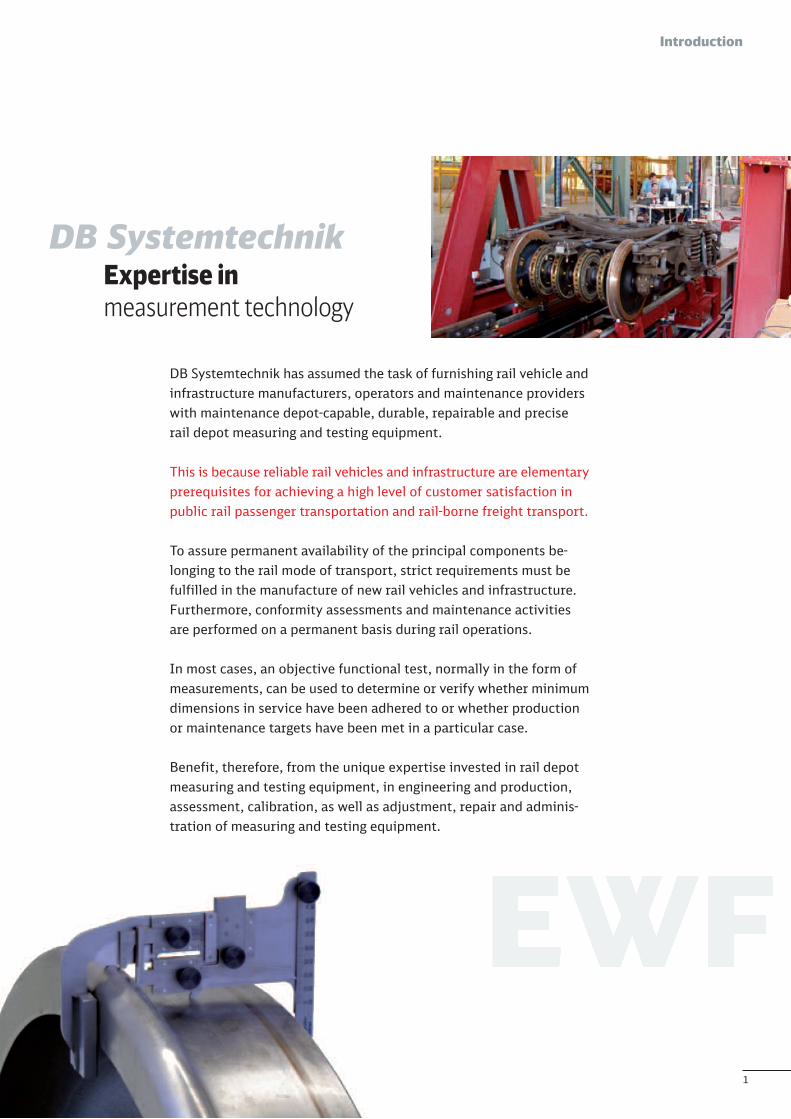
DB SystemtechnikExpertise inmeasurement technology
DB Systemtechnik has assumed the task of furnishing rail vehicle andinfrastructure manufacturers, operators and maintenance providerswith maintenance depot-capable, durable, repairable and preciserail depot measuring and testing equipment.
This is because reliable rail vehicles and infrastructure are elementaryprerequisites for achieving a high level of customer satisfaction inpublic rail passenger transportation and rail-borne freight transport.
To assure permanent availability of the principal components be-longing to the rail mode of transport, strict requirements must befulfilled in the manufacture of new rail vehicles and infrastructure.Furthermore, conformity assessments and maintenance activitiesare performed on a permanent basis during rail operations.
In most cases, an objective functional test, normally in the form ofmeasurements, can be used to determine or verify whether minimumdimensions in service have been adhered to or whether productionor maintenance targets have been met in a particular case.
Benefit, therefore, from the unique expertise invested in rail depotmeasuring and testing equipment, in engineering and production,assessment, calibration, as well as adjustment, repair and adminis-tration of measuring and testing equipment.
2
Contents
1 Rail depot measuring and testing equipmentRange of rail depot measuring and testing equipment 3Making the right selection 3
2 About us: our services, our expertiseDesign and production: Manufacture of typical railway measuring and testing equipment 4Calibration and testing: Monitoring measuring and testingequipment in accordance with DIN EN ISO 17025 4Inspection, measurement and assessment: Proof of suitability of measuring and testing equipment and measurement processes 5
3 Guide to the catalogueGeneral notes 6Catalogue structure 6Notes on ordering and contact details 6
4 Overviews (EWF 5500) 8
5 Mechanical measuring equipment (EWF 5571 – EWF 5593)5.1 Measuring equipment for inner and outer dimensions 145.2 Measuring equipment for miscellaneous or combined dimensions 185.3 Measuring equipment for determining of position 365.4 Other measuring equipment 39
6 Measuring aid equipment and devices for dimension embodiment (EWF 5511 – EWF 5555) 41
7 Gauges (EWF 5561 – EWF 5568)7.1 Gauges for inner dimensions 457.2 Gauges for outer dimensions 527.3 Gauges for other dimensions and shapes 63
8 Appendix8.1 Technical notes 708.2 Index of EWF-number 708.3 Keyword index 71
Rail depot measuring and testing equipment catalogueAs at September 2016
3
Rail depot measuring and testing equipment
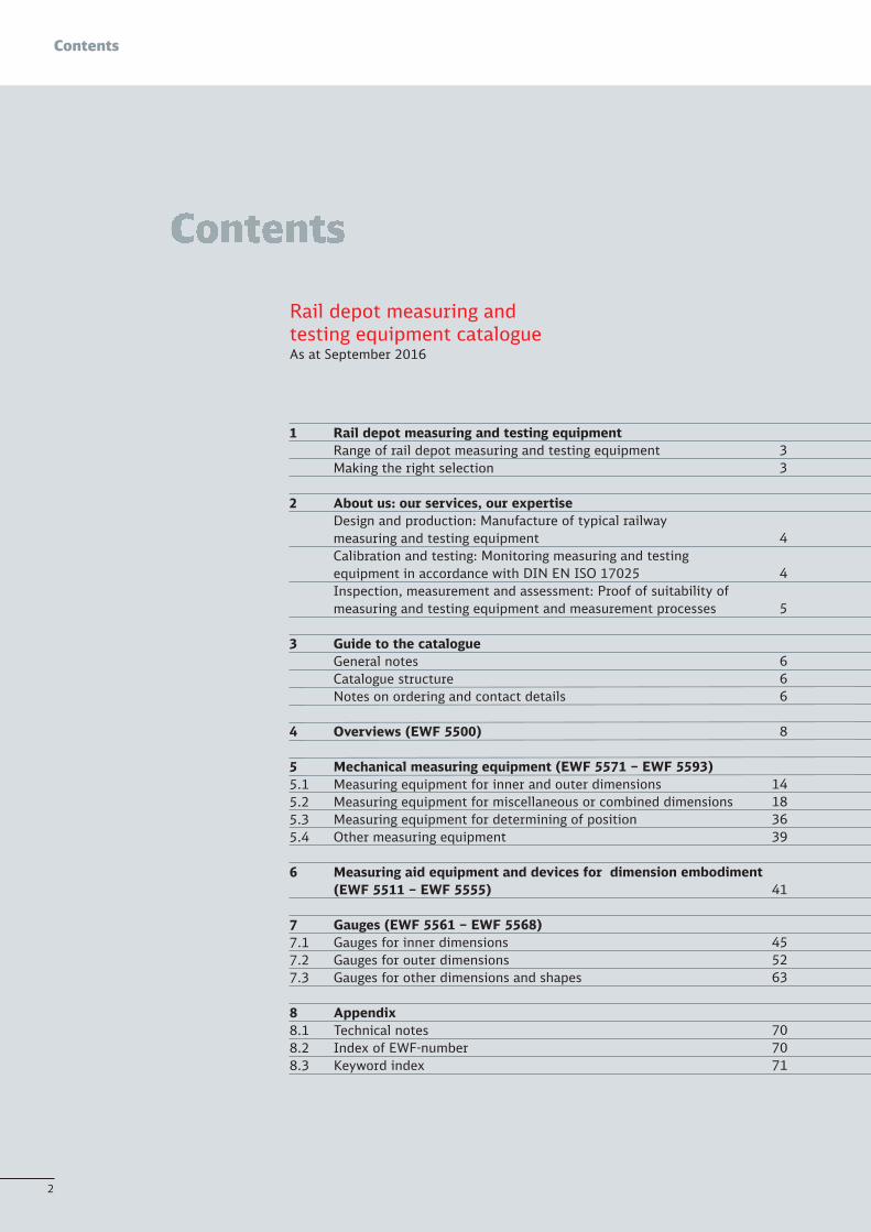
Our rail depot measuring and testing equipment range
The rail depot measuring and testing equipment offered rangesfrom equipment for all standard railway track gauges to tramsand secondary lines. The generic term rail depot measuring andtesting equipment stands for several kinds of measuring andtesting equipment:
I Measuring equipmentI Testing equipmentI Measuring and testing toolsI Devices
This catalogue provides an overview and contains an excerpt from ourproduct range. Additions are constantly being made to our productrange. On the one hand, new rail vehicles are being developed on apermanent basis. In many cases, they call for testing and inspectionof specific characteristics, which have to be detected reliably withoutmuch effort under depot conditions. On the other hand, the measure- ment conditions on familiar rail vehicles may change to such an ex-tent that measurements can no longer be conducted meaningfully.In both cases, our engineers will find a solution for your measuringand testing task.
Is an item of rail depot measuring and testing equipment suitablefor its intended purpose?This question must be answered before a new measuring and testingdevice is procured. Besides considerations regarding clearances on ameasured object and handling of measuring equipment, special at-tention must be paid to the issue of measurement uncertainty underworking conditions. This must be known (DIN EN ISO 10012) and besuitably commensurate with the tolerance defined for the character-istic to be tested.
For every item belonging to our rail depot measuring and testingequipment, we can provide realistic details of measurement uncer-tainty under production conditions, enabling a well-founded decisionfor or against using a certain item of equipment. If none of our listedproducts should comply with your requirements, our engineers willbe pleased to develop a solution for your specific measuring task.
4
About us
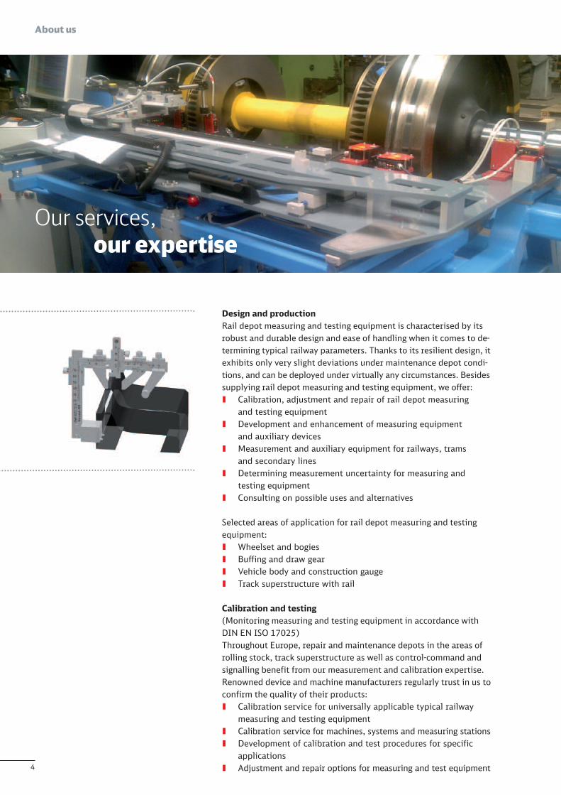
Design and productionRail depot measuring and testing equipment is characterised by itsrobust and durable design and ease of handling when it comes to de-termining typical railway parameters. Thanks to its resilient design, itexhibits only very slight deviations under maintenance depot condi-tions, and can be deployed under virtually any circumstances. Besidessupplying rail depot measuring and testing equipment, we offer:I Calibration, adjustment and repair of rail depot measuring
and testing equipmentI Development and enhancement of measuring equipment
and auxiliary devicesI Measurement and auxiliary equipment for railways, trams
and secondary linesI Determining measurement uncertainty for measuring and
testing equipmentI Consulting on possible uses and alternatives
Selected areas of application for rail depot measuring and testingequipment:I Wheelset and bogiesI Buffing and draw gearI Vehicle body and construction gaugeI Track superstructure with rail
Calibration and testing(Monitoring measuring and testing equipment in accordance withDIN EN ISO 17025)Throughout Europe, repair and maintenance depots in the areas ofrolling stock, track superstructure as well as control-command andsignalling benefit from our measurement and calibration expertise.Renowned device and machine manufacturers regularly trust in us toconfirm the quality of their products:I Calibration service for universally applicable typical railway
measuring and testing equipmentI Calibration service for machines, systems and measuring stationsI Development of calibration and test procedures for specific
applicationsI Adjustment and repair options for measuring and test equipment
Our services, our expertise
5
About us
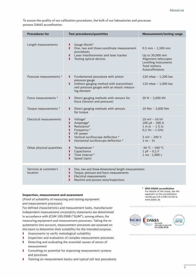
To assure the quality of our calibration procedures, the bulk of our laboratories and processespossess DAkkS accreditation.
* With DAkkS accreditationFor details of the scope, see the appendix to the accreditation certificate D-K-11081-02-00 at www.dakks.de
Test procedures/quantities
I Gauge blocks*I One, two and three-coordinate measurement
proceduresI Laser interferometer and laser trackerI Testing optical devices
I Fundamental procedure with piston pressure gauge
I Indirect gauging method with transmitters and pressure gauges with an elastic measur-ing element
I Direct gauging methods with sensors for force (tension and pressure)
I Direct gauging methods with sensors for torque
I Voltage*I Amperage*I Resistance*I Frequency *I HF powerI Vertical oscilloscope deflection *I Horizontal oscilloscope deflection *
I Temperature *I CapacitanceI Time interval *I Speed (rpm)
Measurement/testing range
0.5 mm – 1,500 mm
Up to 30,000 mmAlignment telescopesLevelling instrumentsTotal stationsAutocollimators
120 mbar – 1,200 bar
120 mbar – 1,000 bar
50 N – 3,000 kN
10 Nm – 3,000 Nm
10 mV – 50 kV 100 µA – 300 A 1 m Ω – 1 GΩ0,1 Hz – 1 GHz
5 mV – 200 V 1 ns – 5s
-30 °C – 500 °C 1 pF – 0,1 F1 ms - 1,000 s
Procedures for
Length measurements
Pressure measurements *
Force measurements *
Torque measurements *
Electrical measurements
Other physical quantities
Services at customer'slocation
I One, two and three-dimensional length measurementsI Torque, pressure and force measurementsI Electrical measurementsI Machine and process tests/inspections
Inspection, measurement and assessment(Proof of suitability of measuring and testing equipment and measurement processes)For defined characteristics and measurement tasks, manufacturer-independent measurement uncertainty statements are determinedin accordance with JCGM 100:2008 ("GUM"), among others, formeasuring equipment and measurement processes. Taking the re-quirements into account, measurement processes are assessed onthis basis to determine their suitability for the intended purpose:I Assessments to verify metrological suitabilityI Inspection and evaluation of complex measurement processesI Detecting and evaluating the essential causes of errors of
measurementI Consulting on potential for improving measurement systems
and processesI Training on measurement basics and typical rail test procedures
6
Catalogue structure
General notesThis catalogue serves to enable a clear search for rail depot measur-ing and testing equipment. Due to the large amount of information,the specifications of individual products are only reproduced to alimited extent in this catalogue. Equally, notes on one-off productionor on using measuring and test devices are only assigned to theirrelevant product groups.
Therefore, please contact our sales department if you wish to obtainmore detailed information or advice on specific measurement ortesting tasks. Sales staff will assist you with additional details andapplication notes when it comes to selection and ordering. For spe-cific measurement or testing tasks, our engineering department is atyour disposal if you wish to clarify certain product characteristics ordiscuss an adapted engineering design.
Catalogue structure
Systematic classification In this catalogue, measuring and test equipment is grouped together in chapters according to the measure-ment task
Index An index making it easier to find per-tinent measuring or test equipment according to its EWF number can be found at the end of the catalogue
Key word indexs A key word index at the end of the catalogue will help you to search for certain equipment according to a measurement or testing task or characteristic.
Notes on ordering and contact detailsDue to the fact that products are designed with a specific customer orapplication in mind, the catalogue does not list any detailed prices or or-dering information. Therefore, you are kindly asked to contact our salesor development department so we can draw up bids tailored to yourneeds.
All previous publications are rendered invalid on publication of this catalogue. All specifi-cations reflect the current state of the art. Technical changes and deletion of individualitems reserved. No liability is accepted for printing errors. Reprinting and reproduction,in whole or in part, are only permitted with our approval.
Sales contact: Heidi Urbanphone: +49 (0) 371 493 - 2011 fax: +49 (0) 371 493 - 2030 [email protected]
Engineering contact: Norbert Winkler phone: +49 (0) 371 493 - [email protected]
Catalogue structure andimportant notes

7
Our products
8
4 Overviews (EWF 5500)
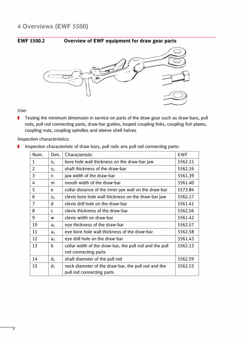
EWF 5500.2 Overview of EWF equipment for draw gear parts
Use:
Testing the minimum dimension in service on parts of the draw gear such as draw-bars, pull
rods, pull rod connecting parts, draw-bar guides, looped coupling links, coupling fish plates,
coupling nuts, coupling spindles and sleeve shell halves
Inspection characteristics:
Inspection characteristic of draw-bars, pull rods ans pull rod connecting parts:
Num. Dim. Characteristic EWF
1 s1 bore hole wall thickness on the draw-bar jaw 5562.15
2 s2 shaft thickness of the draw-bar 5562.16
3 n jaw width of the draw-bar 5561.39
4 m mouth width of the draw-bar 5561.40
5 e collar distance of the inner jaw wall on the draw-bar 5573.84
6 s3 clevis bore hole wall thickness on the draw-bar jaw 5562.17
7 d clevis drill hole on the draw-bar 5561.41
8 c clevis thickness of the draw-bar 5562.56
9 w clevis width on draw-bar 5561.42
10 a1 eye thickness of the draw-bar 5562.57
11 a2 eye bore hole wall thickness of the draw-bar 5562.58
12 a3 eye drill hole on the draw-bar 5561.43
13 b collar width of the draw-bar, the pull rod and the pull
rod connecting parts
5562.13
14 d1 shaft diameter of the pull rod 5562.59
15 d2 neck diameter of the draw-bar, the pull rod and the
pull rod connecting parts
5562.53
9
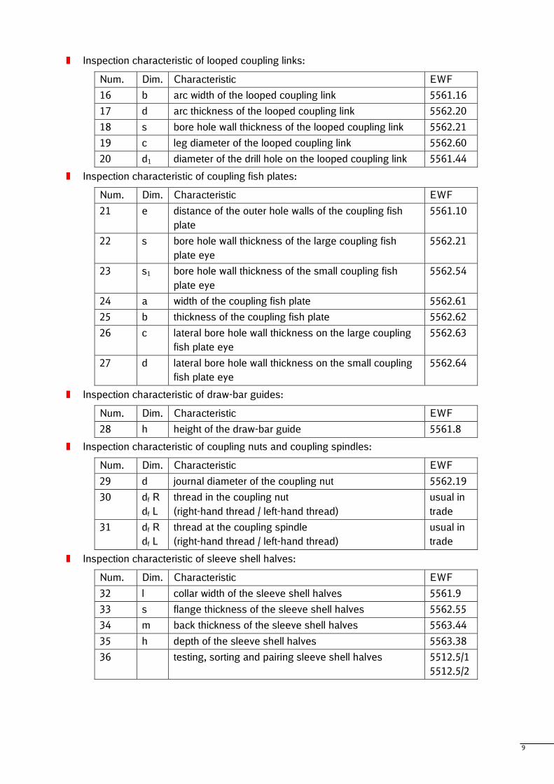
Inspection characteristic of looped coupling links:
Num. Dim. Characteristic EWF
16 b arc width of the looped coupling link 5561.16
17 d arc thickness of the looped coupling link 5562.20
18 s bore hole wall thickness of the looped coupling link 5562.21
19 c leg diameter of the looped coupling link 5562.60
20 d1 diameter of the drill hole on the looped coupling link 5561.44
Inspection characteristic of coupling fish plates:
Num. Dim. Characteristic EWF
21 e distance of the outer hole walls of the coupling fish
plate
5561.10
22 s bore hole wall thickness of the large coupling fish
plate eye
5562.21
23 s1 bore hole wall thickness of the small coupling fish
plate eye
5562.54
24 a width of the coupling fish plate 5562.61
25 b thickness of the coupling fish plate 5562.62
26 c lateral bore hole wall thickness on the large coupling
fish plate eye
5562.63
27 d lateral bore hole wall thickness on the small coupling
fish plate eye
5562.64
Inspection characteristic of draw-bar guides:
Num. Dim. Characteristic EWF
28 h height of the draw-bar guide 5561.8
Inspection characteristic of coupling nuts and coupling spindles:
Num. Dim. Characteristic EWF
29 d journal diameter of the coupling nut 5562.19
30 df R
df L
thread in the coupling nut
(right-hand thread / left-hand thread)
usual in
trade
31 df R
df L
thread at the coupling spindle
(right-hand thread / left-hand thread)
usual in
trade
Inspection characteristic of sleeve shell halves:
Num. Dim. Characteristic EWF
32 l collar width of the sleeve shell halves 5561.9
33 s flange thickness of the sleeve shell halves 5562.55
34 m back thickness of the sleeve shell halves 5563.44
35 h depth of the sleeve shell halves 5563.38
36 testing, sorting and pairing sleeve shell halves 5512.5/1
5512.5/2
10
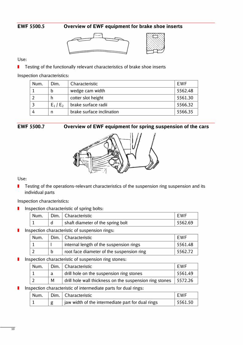
EWF 5500.5 Overview of EWF equipment for brake shoe inserts
Use:
Testing of the functionally relevant characteristics of brake shoe inserts
Inspection characteristics:
Num. Dim. Characteristic EWF
1 b wedge cam width 5562.48
2 h cotter slot height 5561.30
3 E1 / E2 brake surface radii 5566.32
4 n brake surface inclination 5566.35
EWF 5500.7 Overview of EWF equipment for spring suspension of the cars
Use:
Testing of the operations-relevant characteristics of the suspension ring suspension and its
individual parts
Inspection characteristics:
Inspection characteristic of spring bolts:
Num. Dim. Characteristic EWF
1 d shaft diameter of the spring bolt 5562.69
Inspection characteristic of suspension rings:
Num. Dim. Characteristic EWF
1 l internal length of the suspension rings 5561.48
2 b root face diameter of the suspension ring 5562.72
Inspection characteristic of suspension ring stones:
Num. Dim. Characteristic EWF
1 a drill hole on the suspension ring stones 5561.49
2 M drill hole wall thickness on the suspension ring stones 5572.26
Inspection characteristic of intermediate parts for dual rings:
Num. Dim. Characteristic EWF
1 g jaw width of the intermediate part for dual rings 5561.50
11
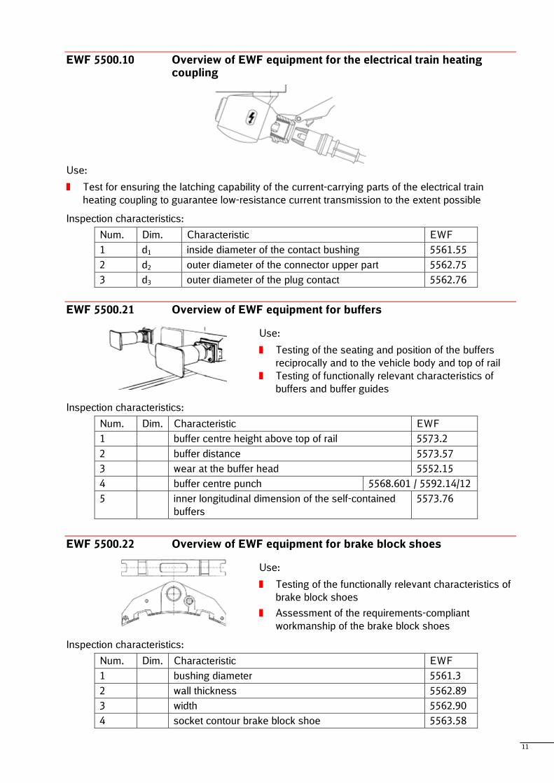
EWF 5500.10 Overview of EWF equipment for the electrical train heating coupling
Use:
Test for ensuring the latching capability of the current-carrying parts of the electrical train
heating coupling to guarantee low-resistance current transmission to the extent possible
Inspection characteristics:
Num. Dim. Characteristic EWF
1 d1 inside diameter of the contact bushing 5561.55
2 d2 outer diameter of the connector upper part 5562.75
3 d3 outer diameter of the plug contact 5562.76
EWF 5500.21 Overview of EWF equipment for buffers
Use:
Testing of the seating and position of the buffers
reciprocally and to the vehicle body and top of rail
Testing of functionally relevant characteristics of
buffers and buffer guides
Inspection characteristics:
Num. Dim. Characteristic EWF
1 buffer centre height above top of rail 5573.2
2 buffer distance 5573.57
3 wear at the buffer head 5552.15
4 buffer centre punch 5568.601 / 5592.14/12
5 inner longitudinal dimension of the self-contained
buffers
5573.76
EWF 5500.22 Overview of EWF equipment for brake block shoes
Use:
Testing of the functionally relevant characteristics of
brake block shoes
Assessment of the requirements-compliant
workmanship of the brake block shoes
Inspection characteristics:
Num. Dim. Characteristic EWF
1 bushing diameter 5561.3
2 wall thickness 5562.89
3 width 5562.90
4 socket contour brake block shoe 5563.58
12
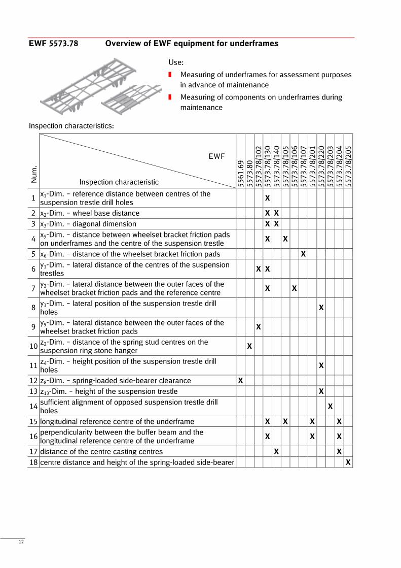
EWF 5573.78 Overview of EWF equipment for underframes
Use:
Measuring of underframes for assessment purposes
in advance of maintenance
Measuring of components on underframes during
maintenance
Inspection characteristics:
Nu
m.
EWF Inspection characteristic 5
56
1.6
9
557
3.8
0
557
3.7
8/1
02
557
3.7
8/1
30
557
3.7
8/1
40
557
3.7
8/1
05
557
3.7
8/1
06
557
3.7
8/1
07
557
3.7
8/2
01
557
3.7
8/2
20
557
3.7
8/2
03
557
3.7
8/2
04
557
3.7
8/2
05
1 x1-Dim. – reference distance between centres of the suspension trestle drill holes
X
2 x2-Dim. – wheel base distance X X
3 x3-Dim. – diagonal dimension X X
4 x5-Dim. – distance between wheelset bracket friction pads on underframes and the centre of the suspension trestle
X X
5 x6-Dim. – distance of the wheelset bracket friction pads X
6 y1-Dim. – lateral distance of the centres of the suspension trestles
X X
7 y2-Dim. – lateral distance between the outer faces of the wheelset bracket friction pads and the reference centre
X X
8 y3-Dim. – lateral position of the suspension trestle drill holes
X
9 y9-Dim. – lateral distance between the outer faces of the wheelset bracket friction pads
X
10 z2-Dim. – distance of the spring stud centres on the suspension ring stone hanger
X
11 z4-Dim. – height position of the suspension trestle drill holes
X
12 z8-Dim. – spring-loaded side-bearer clearance X
13 z13-Dim. – height of the suspension trestle X
14 sufficient alignment of opposed suspension trestle drill holes
X
15 longitudinal reference centre of the underframe X X X X
16 perpendicularity between the buffer beam and the longitudinal reference centre of the underframe
X X X
17 distance of the centre casting centres X X
18 centre distance and height of the spring-loaded side-bearer X
13
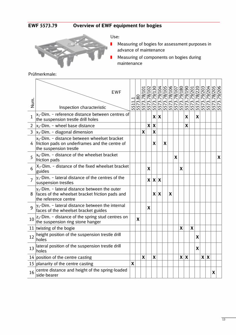
EWF 5573.79 Overview of EWF equipment for bogies
Use:
Measuring of bogies for assessment purposes in
advance of maintenance
Measuring of components on bogies during
maintenance
Prüfmerkmale:
Nu
m.
EWF Inspection characteristic 5
51
1.1
5
57
3.8
0
557
3.7
8/1
01
557
3.7
8/1
02
557
3.7
9/1
30
557
3.7
9/1
04
557
3.7
8/1
05
557
3.7
8/1
06
557
3.7
8/1
07
557
3.7
9/1
80
557
3.7
9/1
90
557
3.7
9/2
01
557
3.7
8/2
20
557
3.7
9/2
03
557
3.7
9/2
04
557
3.7
8/2
05
557
3.7
9/2
06
1 x1-Dim. – reference distance between centres of the suspension trestle drill holes
X X X X
2 x2-Dim. – wheel base distance X X X
3 x3-Dim. – diagonal dimension X X
4 x5-Dim. – distance between wheelset bracket friction pads on underframes and the centre of the suspension trestle
X X
5 x6-Dim. – distance of the wheelset bracket friction pads
X X
6 X7-Dim. – distance of the fixed wheelset bracket guides
X X
7 y1-Dim. – lateral distance of the centres of the suspension trestles
X X X
8 y2-Dim. – lateral distance between the outer faces of the wheelset bracket friction pads and the reference centre
X X X
9 y5-Dim. – lateral distance between the internal faces of the wheelset bracket guides
X
10 z2-Dim. – distance of the spring stud centres on the suspension ring stone hanger
X
11 twisting of the bogie X X
12 height position of the suspension trestle drill holes
X
13 lateral position of the suspension trestle drill holes
X
14 position of the centre casting X X X X X X
15 planarity of the centre casting X
16 centre distance and height of the spring-loaded side-bearer
X
14
5 Mechanical measuring equipment (EWF 5571 – EWF 5593)
5.1 Measuring equipment for inner and outer dimensions
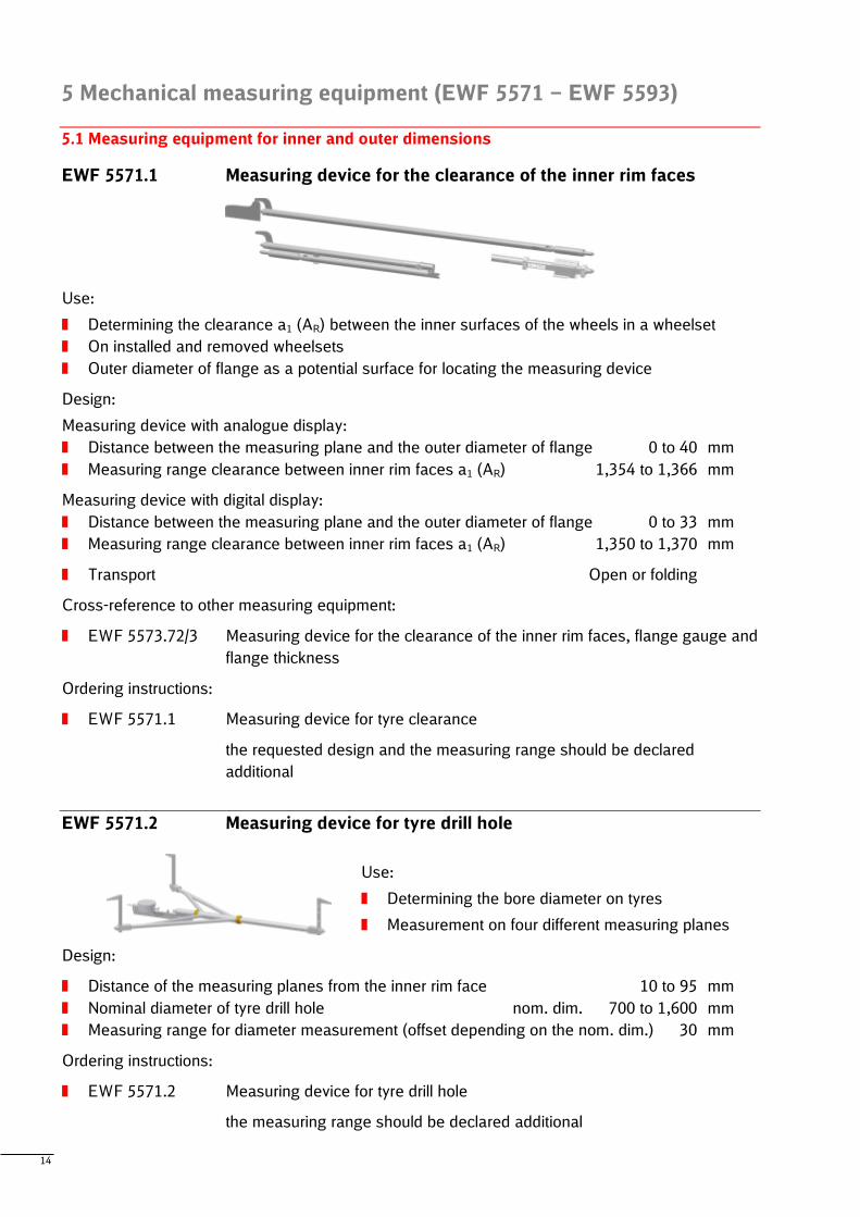
EWF 5571.1 Measuring device for the clearance of the inner rim faces
Use:
Determining the clearance a1 (AR) between the inner surfaces of the wheels in a wheelset
On installed and removed wheelsets
Outer diameter of flange as a potential surface for locating the measuring device
Design:
Measuring device with analogue display:
Distance between the measuring plane and the outer diameter of flange 0 to 40 mm
Measuring range clearance between inner rim faces a1 (AR) 1,354 to 1,366 mm
Measuring device with digital display:
Distance between the measuring plane and the outer diameter of flange 0 to 33 mm
Measuring range clearance between inner rim faces a1 (AR) 1,350 to 1,370 mm
Transport Open or folding
Cross-reference to other measuring equipment:
EWF 5573.72/3 Measuring device for the clearance of the inner rim faces, flange gauge and
flange thickness
Ordering instructions:
EWF 5571.1 Measuring device for tyre clearance
the requested design and the measuring range should be declared
additional
EWF 5571.2 Measuring device for tyre drill hole
Use:
Determining the bore diameter on tyres
Measurement on four different measuring planes
Design:
Distance of the measuring planes from the inner rim face 10 to 95 mm
Nominal diameter of tyre drill hole nom. dim. 700 to 1,600 mm
Measuring range for diameter measurement (offset depending on the nom. dim.) 30 mm
Ordering instructions:
EWF 5571.2 Measuring device for tyre drill hole
the measuring range should be declared additional
15
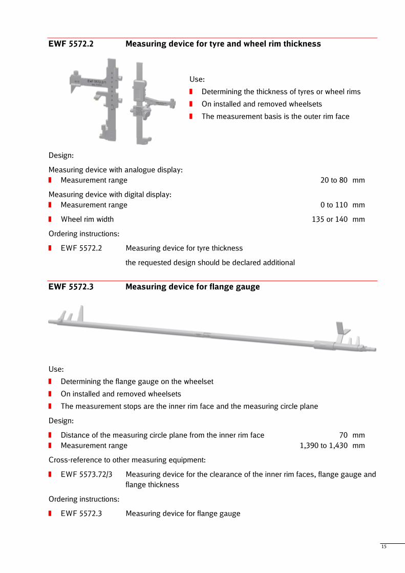
EWF 5572.2 Measuring device for tyre and wheel rim thickness
Use:
Determining the thickness of tyres or wheel rims
On installed and removed wheelsets
The measurement basis is the outer rim face
Design:
Measuring device with analogue display:
Measurement range 20 to 80 mm
Measuring device with digital display:
Measurement range 0 to 110 mm
Wheel rim width 135 or 140 mm
Ordering instructions:
EWF 5572.2 Measuring device for tyre thickness
the requested design should be declared additional
EWF 5572.3 Measuring device for flange gauge
Use:
Determining the flange gauge on the wheelset
On installed and removed wheelsets
The measurement stops are the inner rim face and the measuring circle plane
Design:
Distance of the measuring circle plane from the inner rim face 70 mm
Measurement range 1,390 to 1,430 mm
Cross-reference to other measuring equipment:
EWF 5573.72/3 Measuring device for the clearance of the inner rim faces, flange gauge and
flange thickness
Ordering instructions:
EWF 5572.3 Measuring device for flange gauge
16
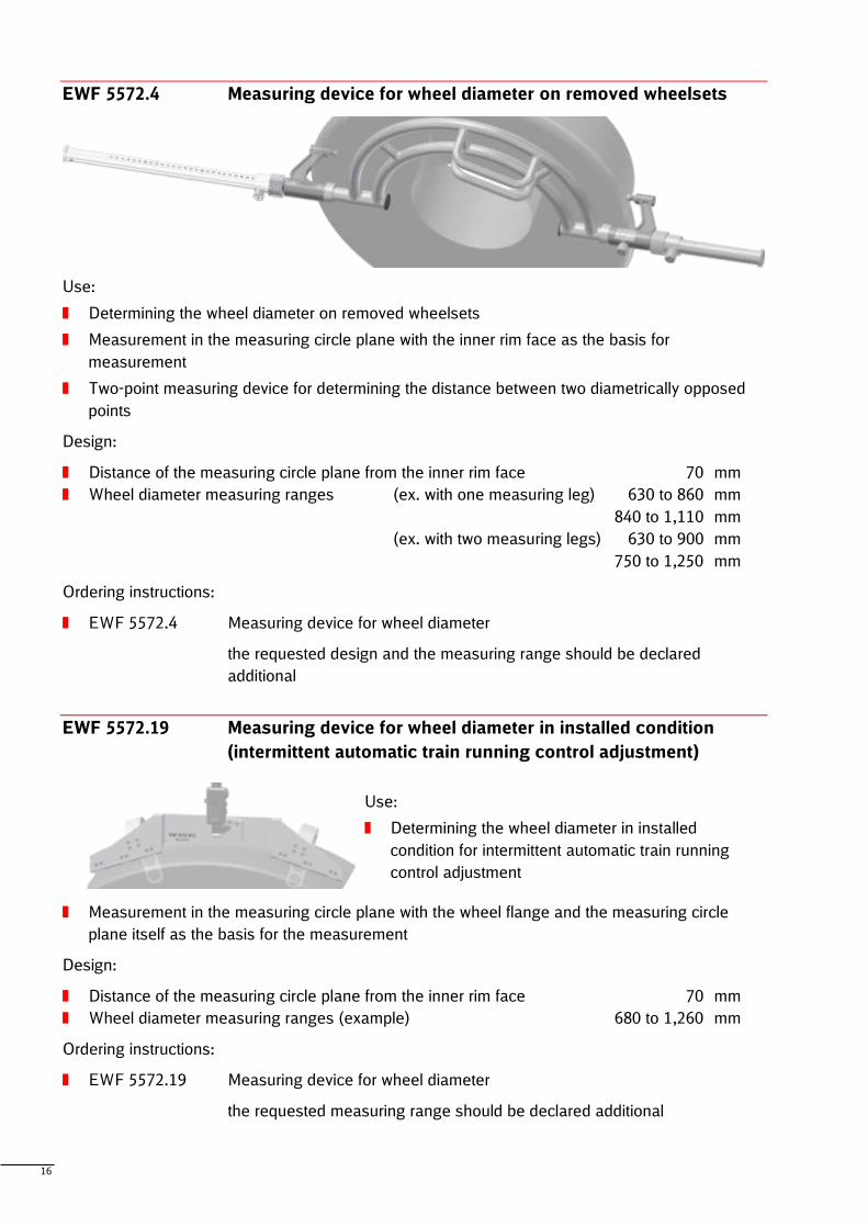
EWF 5572.4 Measuring device for wheel diameter on removed wheelsets
Use:
Determining the wheel diameter on removed wheelsets
Measurement in the measuring circle plane with the inner rim face as the basis for
measurement
Two-point measuring device for determining the distance between two diametrically opposed
points
Design:
Distance of the measuring circle plane from the inner rim face 70 mm
Wheel diameter measuring ranges (ex. with one measuring leg) 630 to 860 mm
840 to 1,110 mm
(ex. with two measuring legs) 630 to 900 mm
750 to 1,250 mm
Ordering instructions:
EWF 5572.4 Measuring device for wheel diameter
the requested design and the measuring range should be declared
additional
EWF 5572.19 Measuring device for wheel diameter in installed condition
(intermittent automatic train running control adjustment)
Use:
Determining the wheel diameter in installed
condition for intermittent automatic train running
control adjustment
Measurement in the measuring circle plane with the wheel flange and the measuring circle
plane itself as the basis for the measurement
Design:
Distance of the measuring circle plane from the inner rim face 70 mm
Wheel diameter measuring ranges (example) 680 to 1,260 mm
Ordering instructions:
EWF 5572.19 Measuring device for wheel diameter
the requested measuring range should be declared additional
17
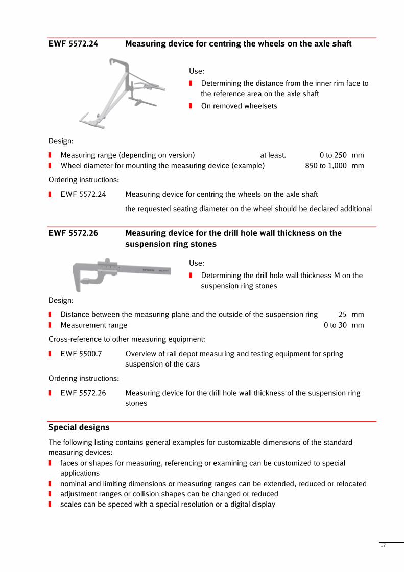
EWF 5572.24 Measuring device for centring the wheels on the axle shaft
Use:
Determining the distance from the inner rim face to
the reference area on the axle shaft
On removed wheelsets
Design:
Measuring range (depending on version) at least. 0 to 250 mm
Wheel diameter for mounting the measuring device (example) 850 to 1,000 mm
Ordering instructions:
EWF 5572.24 Measuring device for centring the wheels on the axle shaft
the requested seating diameter on the wheel should be declared additional
EWF 5572.26 Measuring device for the drill hole wall thickness on the
suspension ring stones
Use:
Determining the drill hole wall thickness M on the
suspension ring stones
Design:
Distance between the measuring plane and the outside of the suspension ring 25 mm
Measurement range 0 to 30 mm
Cross-reference to other measuring equipment:
EWF 5500.7 Overview of rail depot measuring and testing equipment for spring
suspension of the cars
Ordering instructions:
EWF 5572.26 Measuring device for the drill hole wall thickness of the suspension ring
stones
Special designs
The following listing contains general examples for customizable dimensions of the standard
measuring devices:
faces or shapes for measuring, referencing or examining can be customized to special
applications
nominal and limiting dimensions or measuring ranges can be extended, reduced or relocated
adjustment ranges or collision shapes can be changed or reduced
scales can be speced with a special resolution or a digital display
18
5.2 Measuring equipment for miscellaneous or combined dimensions
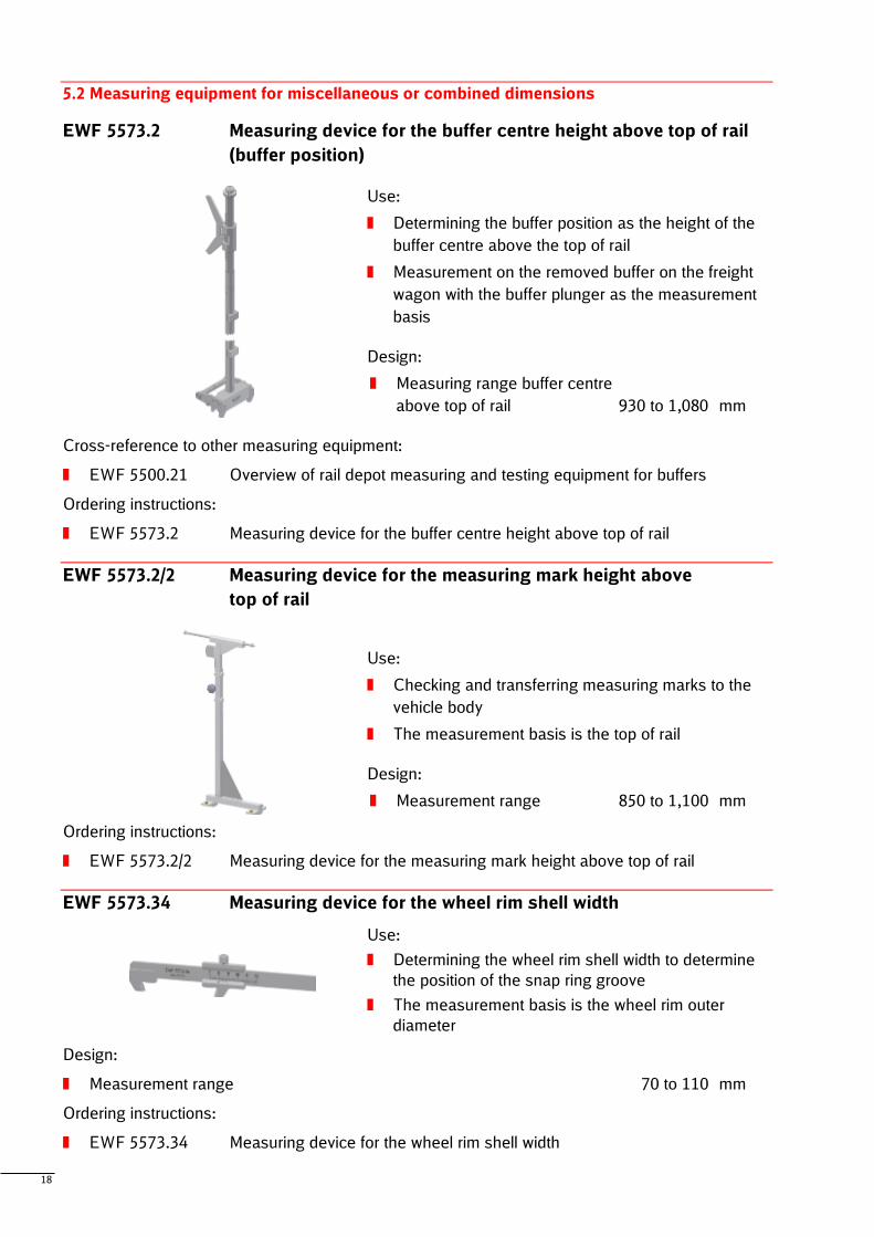
EWF 5573.2 Measuring device for the buffer centre height above top of rail
(buffer position)
Use:
Determining the buffer position as the height of the
buffer centre above the top of rail
Measurement on the removed buffer on the freight
wagon with the buffer plunger as the measurement
basis
Design:
Measuring range buffer centre
above top of rail 930 to 1,080 mm
Cross-reference to other measuring equipment:
EWF 5500.21 Overview of rail depot measuring and testing equipment for buffers
Ordering instructions:
EWF 5573.2 Measuring device for the buffer centre height above top of rail
EWF 5573.2/2 Measuring device for the measuring mark height above
top of rail
Use:
Checking and transferring measuring marks to the
vehicle body
The measurement basis is the top of rail
Design:
Measurement range 850 to 1,100 mm
Ordering instructions:
EWF 5573.2/2 Measuring device for the measuring mark height above top of rail
EWF 5573.34 Measuring device for the wheel rim shell width
Use:
Determining the wheel rim shell width to determine
the position of the snap ring groove
The measurement basis is the wheel rim outer
diameter
Design:
Measurement range 70 to 110 mm
Ordering instructions:
EWF 5573.34 Measuring device for the wheel rim shell width
19
EWF 5573.57 Measuring device for the buffer distance
Use:
Determining the buffer distance to the longitudinal centre line of the car
The measurement basis is the outer diameter of the buffer guides and the longitudinal centre
line of the car marked on the headstock of the car
Design:
Measurement range of the buffer distance
to the longitudinal centre line of the car 855 to 895 mm
Cross-reference to other measuring equipment:
EWF 5500.21 Overview of rail depot measuring and testing equipment for buffers
Ordering instructions:
EWF 5573.57 Measuring device for the buffer distance
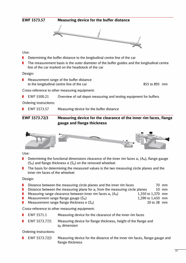
EWF 5573.72/3 Measuring device for the clearance of the inner rim faces, flange
gauge and flange thickness
Use:
Determining the functional dimensions clearance of the inner rim faces a1 (AR), flange gauge
(SR) and flange thickness e (Sd) on the removed wheelset
The basis for determining the measured values is the two measuring circle planes and the
inner rim faces of the wheelset
Design:
Distance between the measuring circle planes and the inner rim faces 70 mm
Distance between the measuring plane for a1 from the measuring circle planes 10 mm
Measuring range clearance between inner rim faces a1 (AR) 1,350 to 1,370 mm
Measurement range flange gauge (SR) 1,390 to 1,450 mm
Measurement range flange thickness e (Sd) 20 to 38 mm
Cross-reference to other measuring equipment:
EWF 5571.1 Measuring device for the clearance of the inner rim faces
EWF 5573.77/1 Measuring device for flange thickness, height of the flange and
qR dimension
Ordering instructions:
EWF 5573.72/3 Measuring device for the distance of the inner rim faces, flange gauge and
flange thickness
20
EWF 5573.76 Measuring device for the inner longitudinal dimension of the
self-contained buffers
Use:
Determining the buffer and plunger depth on the
self-contained buffer
Design:
Width of measurement basis 250 mm
Diameter of guide discs 168 mm
Measurement range 405 to 750 mm
Cross-reference to other measuring equipment:
EWF 5500.21 Overview of rail depot measuring and testing equipment for buffers
Ordering instructions:
EWF 5573.76 Measuring device for the inner longitudinal dimension of the self-contained
buffers
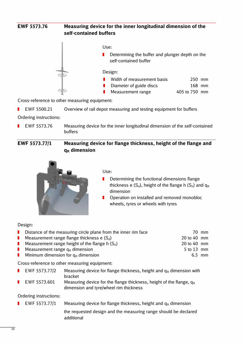
EWF 5573.77/1 Measuring device for flange thickness, height of the flange and
qR dimension
Use:
Determining the functional dimensions flange
thickness e (Sd), height of the flange h (Sh) and qR
dimension
Operation on installed and removed monobloc
wheels, tyres or wheels with tyres
Design:
Distance of the measuring circle plane from the inner rim face 70 mm
Measurement range flange thickness e (Sd) 20 to 40 mm
Measurement range height of the flange h (Sh) 20 to 40 mm
Measurement range qR dimension 5 to 13 mm
Minimum dimension for qR dimension 6.5 mm
Cross-reference to other measuring equipment:
EWF 5573.77/2 Measuring device for flange thickness, height and qR dimension with
bracket
EWF 5573.601 Measuring device for the flange thickness, height of the flange, qR
dimension and tyre/wheel rim thickness
Ordering instructions:
EWF 5573.77/1 Measuring device for flange thickness, height and qR dimension
the requested design and the measuring range should be declared
additional
21
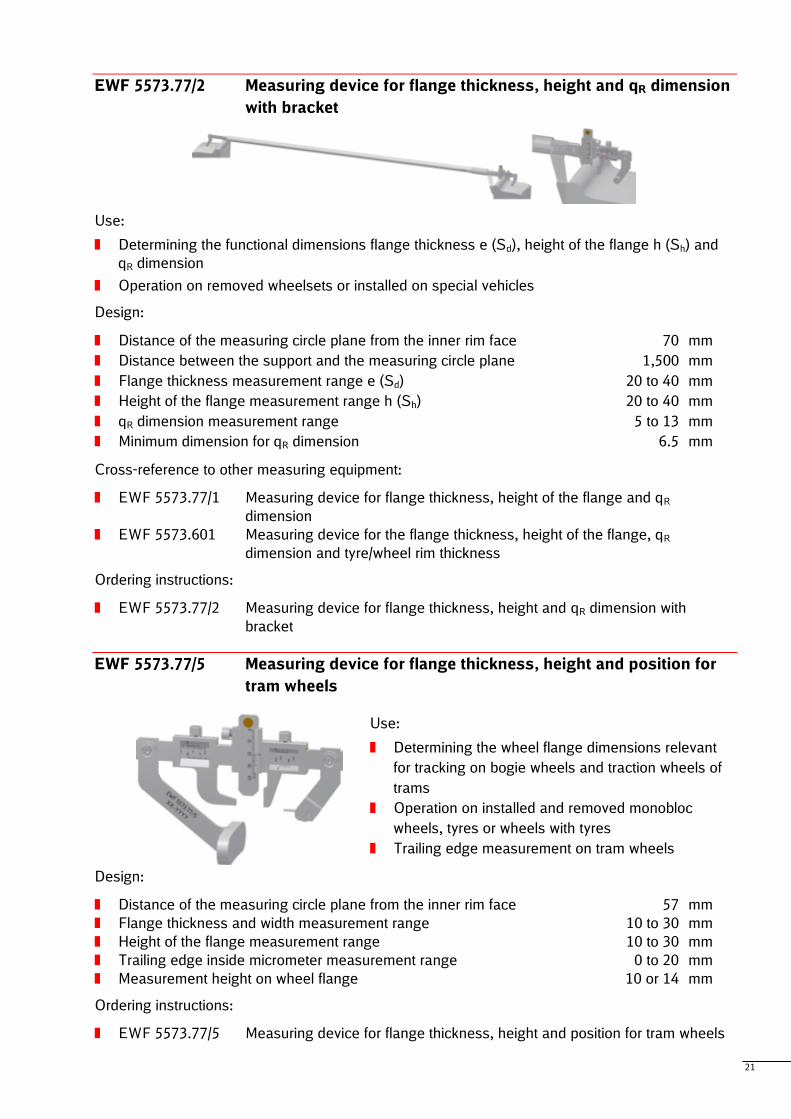
EWF 5573.77/2 Measuring device for flange thickness, height and qR dimension
with bracket
Use:
Determining the functional dimensions flange thickness e (Sd), height of the flange h (Sh) and
qR dimension
Operation on removed wheelsets or installed on special vehicles
Design:
Distance of the measuring circle plane from the inner rim face 70 mm
Distance between the support and the measuring circle plane 1,500 mm
Flange thickness measurement range e (Sd) 20 to 40 mm
Height of the flange measurement range h (Sh) 20 to 40 mm
qR dimension measurement range 5 to 13 mm
Minimum dimension for qR dimension 6.5 mm
Cross-reference to other measuring equipment:
EWF 5573.77/1 Measuring device for flange thickness, height of the flange and qR
dimension
EWF 5573.601 Measuring device for the flange thickness, height of the flange, qR
dimension and tyre/wheel rim thickness
Ordering instructions:
EWF 5573.77/2 Measuring device for flange thickness, height and qR dimension with
bracket
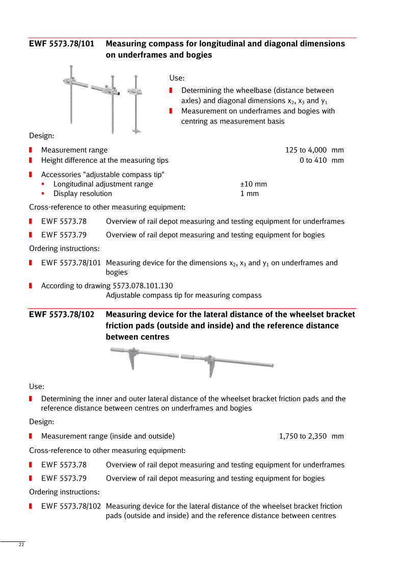
EWF 5573.77/5 Measuring device for flange thickness, height and position for
tram wheels
Use:
Determining the wheel flange dimensions relevant
for tracking on bogie wheels and traction wheels of
trams
Operation on installed and removed monobloc
wheels, tyres or wheels with tyres
Trailing edge measurement on tram wheels
Design:
Distance of the measuring circle plane from the inner rim face 57 mm
Flange thickness and width measurement range 10 to 30 mm
Height of the flange measurement range 10 to 30 mm
Trailing edge inside micrometer measurement range 0 to 20 mm
Measurement height on wheel flange 10 or 14 mm
Ordering instructions:
EWF 5573.77/5 Measuring device for flange thickness, height and position for tram wheels
22
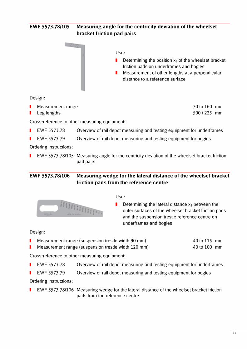
EWF 5573.78/101 Measuring compass for longitudinal and diagonal dimensions
on underframes and bogies
Use:
Determining the wheelbase (distance between
axles) and diagonal dimensions x2, x3 and y1
Measurement on underframes and bogies with
centring as measurement basis
Design:
Measurement range 125 to 4,000 mm
Height difference at the measuring tips 0 to 410 mm
Accessories "adjustable compass tip"
Longitudinal adjustment range ±10 mm
Display resolution 1 mm
Cross-reference to other measuring equipment:
EWF 5573.78 Overview of rail depot measuring and testing equipment for underframes
EWF 5573.79 Overview of rail depot measuring and testing equipment for bogies
Ordering instructions:
EWF 5573.78/101 Measuring device for the dimensions x2, x3 and y1 on underframes and
bogies
According to drawing 5573.078.101.130
Adjustable compass tip for measuring compass
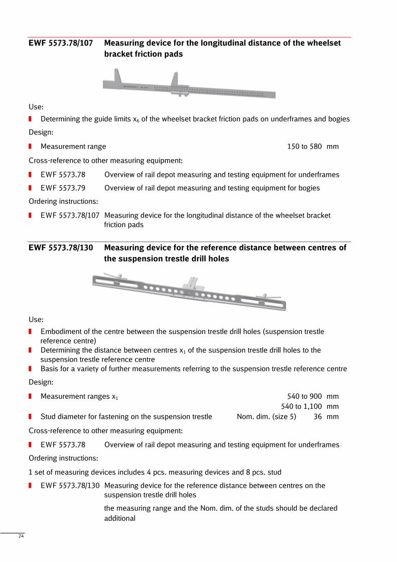
EWF 5573.78/102 Measuring device for the lateral distance of the wheelset bracket
friction pads (outside and inside) and the reference distance
between centres
Use:
Determining the inner and outer lateral distance of the wheelset bracket friction pads and the
reference distance between centres on underframes and bogies
Design:
Measurement range (inside and outside) 1,750 to 2,350 mm
Cross-reference to other measuring equipment:
EWF 5573.78 Overview of rail depot measuring and testing equipment for underframes
EWF 5573.79 Overview of rail depot measuring and testing equipment for bogies
Ordering instructions:
EWF 5573.78/102 Measuring device for the lateral distance of the wheelset bracket friction
pads (outside and inside) and the reference distance between centres
23
EWF 5573.78/105 Measuring angle for the centricity deviation of the wheelset
bracket friction pad pairs
Use:
Determining the position x5 of the wheelset bracket
friction pads on underframes and bogies
Measurement of other lengths at a perpendicular
distance to a reference surface
Design:
Measurement range 70 to 160 mm
Leg lengths 500 / 225 mm
Cross-reference to other measuring equipment:
EWF 5573.78 Overview of rail depot measuring and testing equipment for underframes
EWF 5573.79 Overview of rail depot measuring and testing equipment for bogies
Ordering instructions:
EWF 5573.78/105 Measuring angle for the centricity deviation of the wheelset bracket friction
pad pairs
EWF 5573.78/106 Measuring wedge for the lateral distance of the wheelset bracket
friction pads from the reference centre
Use:
Determining the lateral distance x2 between the
outer surfaces of the wheelset bracket friction pads
and the suspension trestle reference centre on
underframes and bogies
Design:
Measurement range (suspension trestle width 90 mm) 40 to 115 mm
Measurement range (suspension trestle width 120 mm) 40 to 100 mm
Cross-reference to other measuring equipment:
EWF 5573.78 Overview of rail depot measuring and testing equipment for underframes
EWF 5573.79 Overview of rail depot measuring and testing equipment for bogies
Ordering instructions:
EWF 5573.78/106 Measuring wedge for the lateral distance of the wheelset bracket friction
pads from the reference centre
24
EWF 5573.78/107 Measuring device for the longitudinal distance of the wheelset
bracket friction pads
Use:
Determining the guide limits x6 of the wheelset bracket friction pads on underframes and bogies
Design:
Measurement range 150 to 580 mm
Cross-reference to other measuring equipment:
EWF 5573.78 Overview of rail depot measuring and testing equipment for underframes
EWF 5573.79 Overview of rail depot measuring and testing equipment for bogies
Ordering instructions:
EWF 5573.78/107 Measuring device for the longitudinal distance of the wheelset bracket
friction pads
EWF 5573.78/130 Measuring device for the reference distance between centres of
the suspension trestle drill holes
Use:
Embodiment of the centre between the suspension trestle drill holes (suspension trestle
reference centre)
Determining the distance between centres x1 of the suspension trestle drill holes to the
suspension trestle reference centre
Basis for a variety of further measurements referring to the suspension trestle reference centre
Design:
Measurement ranges x1 540 to 900 mm
540 to 1,100 mm
Stud diameter for fastening on the suspension trestle Nom. dim. (size 5) 36 mm
Cross-reference to other measuring equipment:
EWF 5573.78 Overview of rail depot measuring and testing equipment for underframes
Ordering instructions:
1 set of measuring devices includes 4 pcs. measuring devices and 8 pcs. stud
EWF 5573.78/130 Measuring device for the reference distance between centres on the
suspension trestle drill holes
the measuring range and the Nom. dim. of the studs should be declared
additional
25
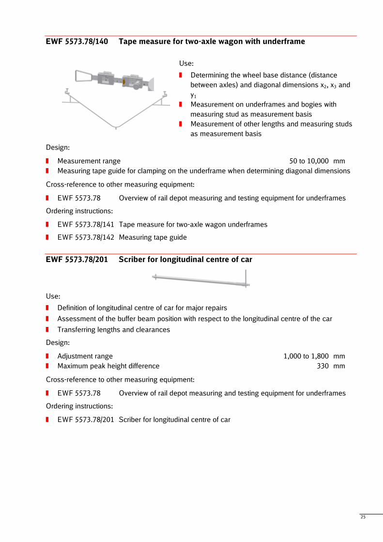
EWF 5573.78/140 Tape measure for two-axle wagon with underframe
Use:
Determining the wheel base distance (distance
between axles) and diagonal dimensions x2, x3 and
y1
Measurement on underframes and bogies with
measuring stud as measurement basis
Measurement of other lengths and measuring studs
as measurement basis
Design:
Measurement range 50 to 10,000 mm
Measuring tape guide for clamping on the underframe when determining diagonal dimensions
Cross-reference to other measuring equipment:
EWF 5573.78 Overview of rail depot measuring and testing equipment for underframes
Ordering instructions:
EWF 5573.78/141 Tape measure for two-axle wagon underframes
EWF 5573.78/142 Measuring tape guide
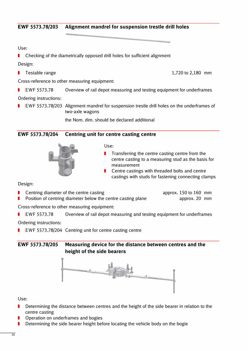
EWF 5573.78/201 Scriber for longitudinal centre of car
Use:
Definition of longitudinal centre of car for major repairs
Assessment of the buffer beam position with respect to the longitudinal centre of the car
Transferring lengths and clearances
Design:
Adjustment range 1,000 to 1,800 mm
Maximum peak height difference 330 mm
Cross-reference to other measuring equipment:
EWF 5573.78 Overview of rail depot measuring and testing equipment for underframes
Ordering instructions:
EWF 5573.78/201 Scriber for longitudinal centre of car
26
EWF 5573.78/203 Alignment mandrel for suspension trestle drill holes
Use:
Checking of the diametrically opposed drill holes for sufficient alignment
Design:
Testable range 1,720 to 2,180 mm
Cross-reference to other measuring equipment:
EWF 5573.78 Overview of rail depot measuring and testing equipment for underframes
Ordering instructions:
EWF 5573.78/203 Alignment mandrel for suspension trestle drill holes on the underframes of
two-axle wagons
the Nom. dim. should be declared additional
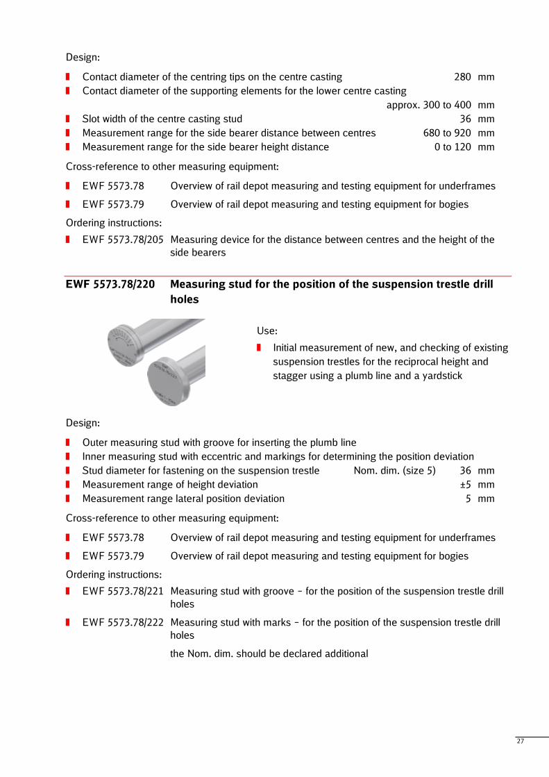
EWF 5573.78/204 Centring unit for centre casting centre
Use:
Transferring the centre casting centre from the
centre casting to a measuring stud as the basis for
measurement
Centre castings with threaded bolts and centre
castings with studs for fastening connecting clamps
Design:
Centring diameter of the centre casting approx. 150 to 160 mm
Position of centring diameter below the centre casting plane approx. 20 mm
Cross-reference to other measuring equipment:
EWF 5573.78 Overview of rail depot measuring and testing equipment for underframes
Ordering instructions:
EWF 5573.78/204 Centring unit for centre casting centre
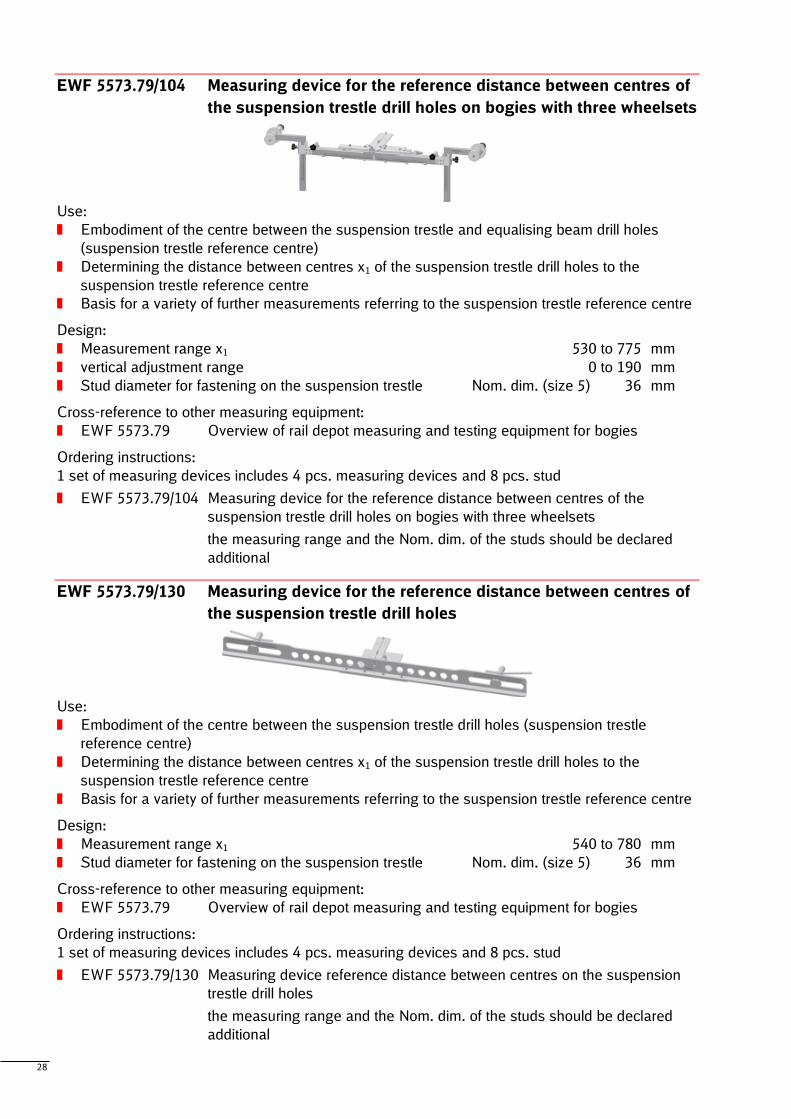
EWF 5573.78/205 Measuring device for the distance between centres and the
height of the side bearers
Use:
Determining the distance between centres and the height of the side bearer in relation to the
centre casting
Operation on underframes and bogies
Determining the side bearer height before locating the vehicle body on the bogie
27
Design:
Contact diameter of the centring tips on the centre casting 280 mm
Contact diameter of the supporting elements for the lower centre casting
approx. 300 to 400 mm
Slot width of the centre casting stud 36 mm
Measurement range for the side bearer distance between centres 680 to 920 mm
Measurement range for the side bearer height distance 0 to 120 mm
Cross-reference to other measuring equipment:
EWF 5573.78 Overview of rail depot measuring and testing equipment for underframes
EWF 5573.79 Overview of rail depot measuring and testing equipment for bogies
Ordering instructions:
EWF 5573.78/205 Measuring device for the distance between centres and the height of the
side bearers
EWF 5573.78/220 Measuring stud for the position of the suspension trestle drill
holes
Use:
Initial measurement of new, and checking of existing
suspension trestles for the reciprocal height and
stagger using a plumb line and a yardstick
Design:
Outer measuring stud with groove for inserting the plumb line
Inner measuring stud with eccentric and markings for determining the position deviation
Stud diameter for fastening on the suspension trestle Nom. dim. (size 5) 36 mm
Measurement range of height deviation ±5 mm
Measurement range lateral position deviation 5 mm
Cross-reference to other measuring equipment:
EWF 5573.78 Overview of rail depot measuring and testing equipment for underframes
EWF 5573.79 Overview of rail depot measuring and testing equipment for bogies
Ordering instructions:
EWF 5573.78/221 Measuring stud with groove – for the position of the suspension trestle drill
holes
EWF 5573.78/222 Measuring stud with marks – for the position of the suspension trestle drill
holes
the Nom. dim. should be declared additional
28
EWF 5573.79/104 Measuring device for the reference distance between centres of
the suspension trestle drill holes on bogies with three wheelsets
Use:
Embodiment of the centre between the suspension trestle and equalising beam drill holes
(suspension trestle reference centre)
Determining the distance between centres x1 of the suspension trestle drill holes to the
suspension trestle reference centre
Basis for a variety of further measurements referring to the suspension trestle reference centre
Design:
Measurement range x1 530 to 775 mm
vertical adjustment range 0 to 190 mm
Stud diameter for fastening on the suspension trestle Nom. dim. (size 5) 36 mm
Cross-reference to other measuring equipment:
EWF 5573.79 Overview of rail depot measuring and testing equipment for bogies
Ordering instructions:
1 set of measuring devices includes 4 pcs. measuring devices and 8 pcs. stud
EWF 5573.79/104 Measuring device for the reference distance between centres of the
suspension trestle drill holes on bogies with three wheelsets
the measuring range and the Nom. dim. of the studs should be declared
additional
EWF 5573.79/130 Measuring device for the reference distance between centres of
the suspension trestle drill holes
Use:
Embodiment of the centre between the suspension trestle drill holes (suspension trestle
reference centre)
Determining the distance between centres x1 of the suspension trestle drill holes to the
suspension trestle reference centre
Basis for a variety of further measurements referring to the suspension trestle reference centre
Design:
Measurement range x1 540 to 780 mm
Stud diameter for fastening on the suspension trestle Nom. dim. (size 5) 36 mm
Cross-reference to other measuring equipment:
EWF 5573.79 Overview of rail depot measuring and testing equipment for bogies
Ordering instructions:
1 set of measuring devices includes 4 pcs. measuring devices and 8 pcs. stud
EWF 5573.79/130 Measuring device reference distance between centres on the suspension
trestle drill holes
the measuring range and the Nom. dim. of the studs should be declared
additional
29
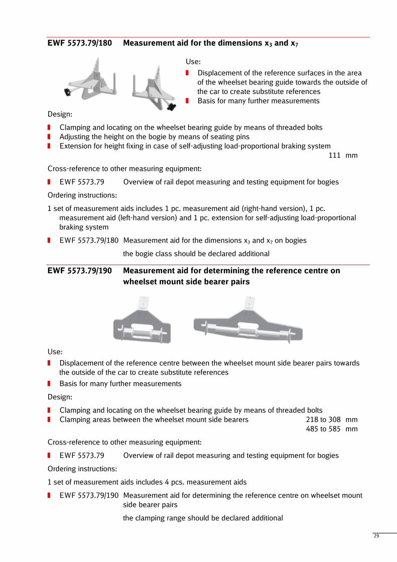
EWF 5573.79/180 Measurement aid for the dimensions x3 and x7
Use:
Displacement of the reference surfaces in the area
of the wheelset bearing guide towards the outside of
the car to create substitute references
Basis for many further measurements
Design:
Clamping and locating on the wheelset bearing guide by means of threaded bolts
Adjusting the height on the bogie by means of seating pins
Extension for height fixing in case of self-adjusting load-proportional braking system
111 mm
Cross-reference to other measuring equipment:
EWF 5573.79 Overview of rail depot measuring and testing equipment for bogies
Ordering instructions:
1 set of measurement aids includes 1 pc. measurement aid (right-hand version), 1 pc.
measurement aid (left-hand version) and 1 pc. extension for self-adjusting load-proportional
braking system
EWF 5573.79/180 Measurement aid for the dimensions x3 and x7 on bogies
the bogie class should be declared additional
EWF 5573.79/190 Measurement aid for determining the reference centre on
wheelset mount side bearer pairs
Use:
Displacement of the reference centre between the wheelset mount side bearer pairs towards
the outside of the car to create substitute references
Basis for many further measurements
Design:
Clamping and locating on the wheelset bearing guide by means of threaded bolts
Clamping areas between the wheelset mount side bearers 218 to 308 mm
485 to 585 mm
Cross-reference to other measuring equipment:
EWF 5573.79 Overview of rail depot measuring and testing equipment for bogies
Ordering instructions:
1 set of measurement aids includes 4 pcs. measurement aids
EWF 5573.79/190 Measurement aid for determining the reference centre on wheelset mount
side bearer pairs
the clamping range should be declared additional
30
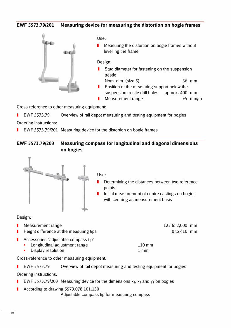
EWF 5573.79/201 Measuring device for measuring the distortion on bogie frames
Use:
Measuring the distortion on bogie frames without
levelling the frame
Design:
Stud diameter for fastening on the suspension
trestle
Nom. dim. (size 5) 36 mm
Position of the measuring support below the
suspension trestle drill holes approx. 400 mm
Measurement range ±5 mm/m
Cross-reference to other measuring equipment:
EWF 5573.79 Overview of rail depot measuring and testing equipment for bogies
Ordering instructions:
EWF 5573.79/201 Measuring device for the distortion on bogie frames
EWF 5573.79/203 Measuring compass for longitudinal and diagonal dimensions
on bogies
Use:
Determining the distances between two reference
points
Initial measurement of centre castings on bogies
with centring as measurement basis
Design:
Measurement range 125 to 2,000 mm
Height difference at the measuring tips 0 to 410 mm
Accessories "adjustable compass tip"
Longitudinal adjustment range ±10 mm
Display resolution 1 mm
Cross-reference to other measuring equipment:
EWF 5573.79 Overview of rail depot measuring and testing equipment for bogies
Ordering instructions:
EWF 5573.79/203 Measuring device for the dimensions x2, x3 and y1 on bogies
According to drawing 5573.078.101.130
Adjustable compass tip for measuring compass
31
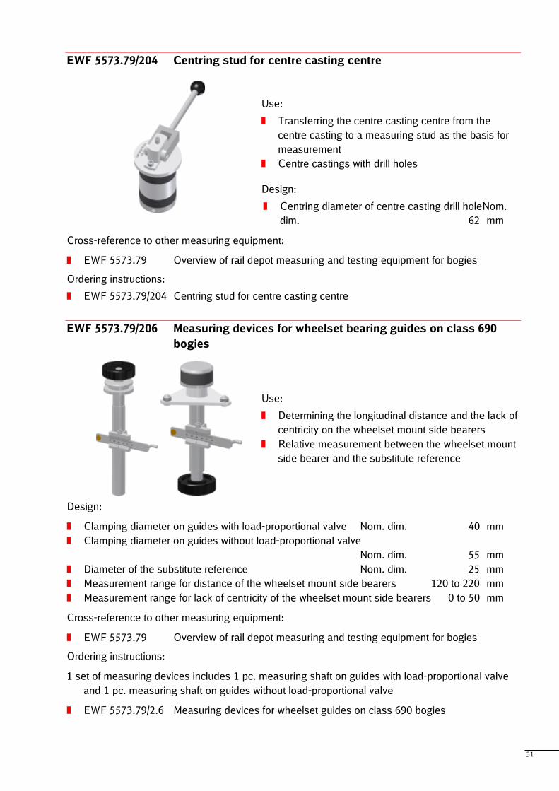
EWF 5573.79/204 Centring stud for centre casting centre
Use:
Transferring the centre casting centre from the
centre casting to a measuring stud as the basis for
measurement
Centre castings with drill holes
Design:
Centring diameter of centre casting drill holeNom.
dim. 62 mm
Cross-reference to other measuring equipment:
EWF 5573.79 Overview of rail depot measuring and testing equipment for bogies
Ordering instructions:
EWF 5573.79/204 Centring stud for centre casting centre
EWF 5573.79/206 Measuring devices for wheelset bearing guides on class 690
bogies
Use:
Determining the longitudinal distance and the lack of
centricity on the wheelset mount side bearers
Relative measurement between the wheelset mount
side bearer and the substitute reference
Design:
Clamping diameter on guides with load-proportional valve Nom. dim. 40 mm
Clamping diameter on guides without load-proportional valve
Nom. dim. 55 mm
Diameter of the substitute reference Nom. dim. 25 mm
Measurement range for distance of the wheelset mount side bearers 120 to 220 mm
Measurement range for lack of centricity of the wheelset mount side bearers 0 to 50 mm
Cross-reference to other measuring equipment:
EWF 5573.79 Overview of rail depot measuring and testing equipment for bogies
Ordering instructions:
1 set of measuring devices includes 1 pc. measuring shaft on guides with load-proportional valve
and 1 pc. measuring shaft on guides without load-proportional valve
EWF 5573.79/2.6 Measuring devices for wheelset guides on class 690 bogies
32
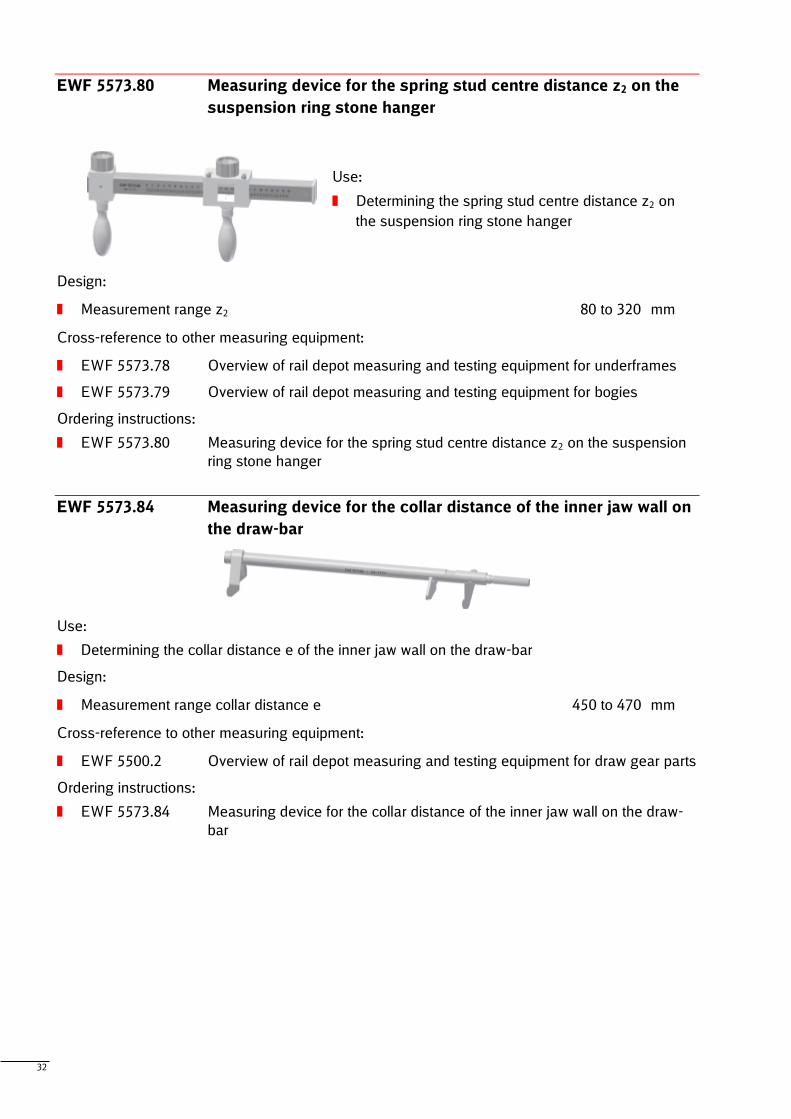
EWF 5573.80 Measuring device for the spring stud centre distance z2 on the
suspension ring stone hanger
Use:
Determining the spring stud centre distance z2 on
the suspension ring stone hanger
Design:
Measurement range z2 80 to 320 mm
Cross-reference to other measuring equipment:
EWF 5573.78 Overview of rail depot measuring and testing equipment for underframes
EWF 5573.79 Overview of rail depot measuring and testing equipment for bogies
Ordering instructions:
EWF 5573.80 Measuring device for the spring stud centre distance z2 on the suspension
ring stone hanger
EWF 5573.84 Measuring device for the collar distance of the inner jaw wall on
the draw-bar
Use:
Determining the collar distance e of the inner jaw wall on the draw-bar
Design:
Measurement range collar distance e 450 to 470 mm
Cross-reference to other measuring equipment:
EWF 5500.2 Overview of rail depot measuring and testing equipment for draw gear parts
Ordering instructions:
EWF 5573.84 Measuring device for the collar distance of the inner jaw wall on the draw-
bar
33
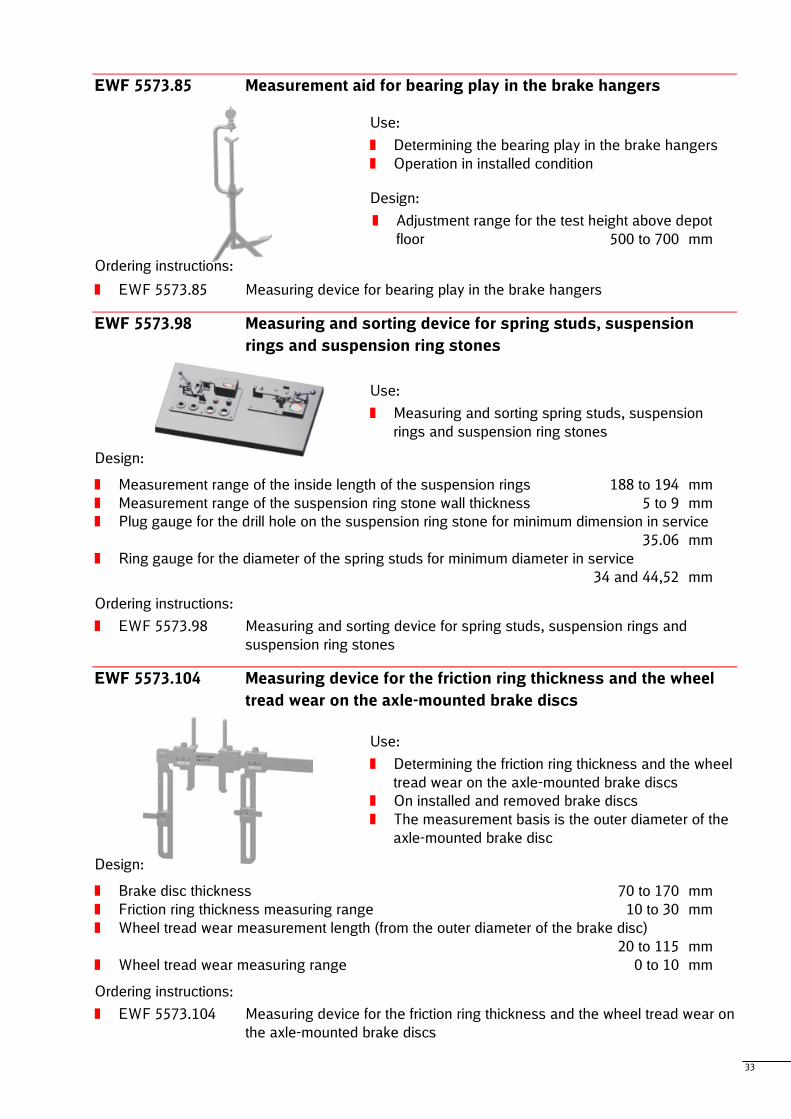
EWF 5573.85 Measurement aid for bearing play in the brake hangers
Use:
Determining the bearing play in the brake hangers
Operation in installed condition
Design:
Adjustment range for the test height above depot
floor 500 to 700 mm
Ordering instructions:
EWF 5573.85 Measuring device for bearing play in the brake hangers
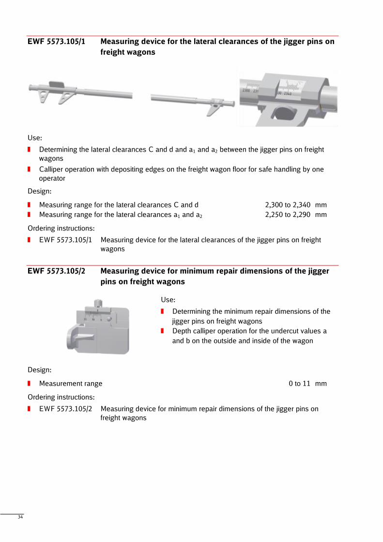
EWF 5573.98 Measuring and sorting device for spring studs, suspension
rings and suspension ring stones
Use:
Measuring and sorting spring studs, suspension
rings and suspension ring stones
Design:
Measurement range of the inside length of the suspension rings 188 to 194 mm
Measurement range of the suspension ring stone wall thickness 5 to 9 mm
Plug gauge for the drill hole on the suspension ring stone for minimum dimension in service
35.06 mm
Ring gauge for the diameter of the spring studs for minimum diameter in service
34 and 44,52 mm
Ordering instructions:
EWF 5573.98 Measuring and sorting device for spring studs, suspension rings and
suspension ring stones
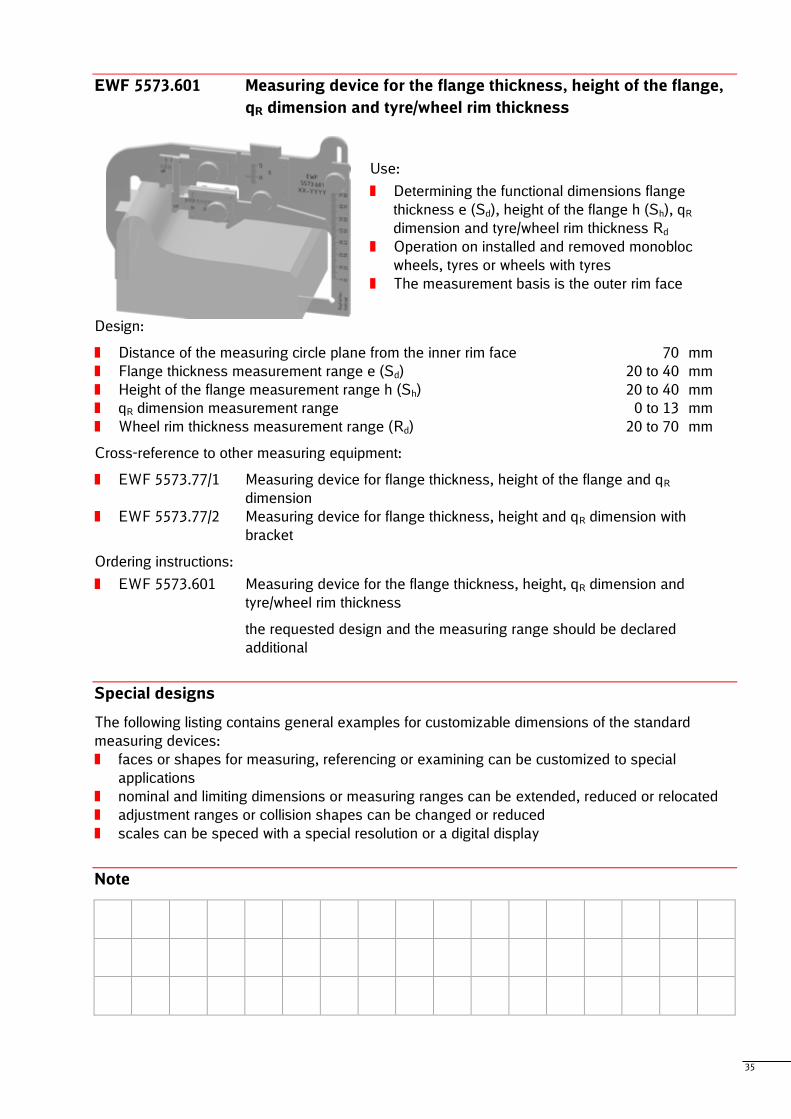
EWF 5573.104 Measuring device for the friction ring thickness and the wheel
tread wear on the axle-mounted brake discs
Use:
Determining the friction ring thickness and the wheel
tread wear on the axle-mounted brake discs
On installed and removed brake discs
The measurement basis is the outer diameter of the
axle-mounted brake disc
Design:
Brake disc thickness 70 to 170 mm
Friction ring thickness measuring range 10 to 30 mm
Wheel tread wear measurement length (from the outer diameter of the brake disc)
20 to 115 mm
Wheel tread wear measuring range 0 to 10 mm
Ordering instructions:
EWF 5573.104 Measuring device for the friction ring thickness and the wheel tread wear on
the axle-mounted brake discs
34
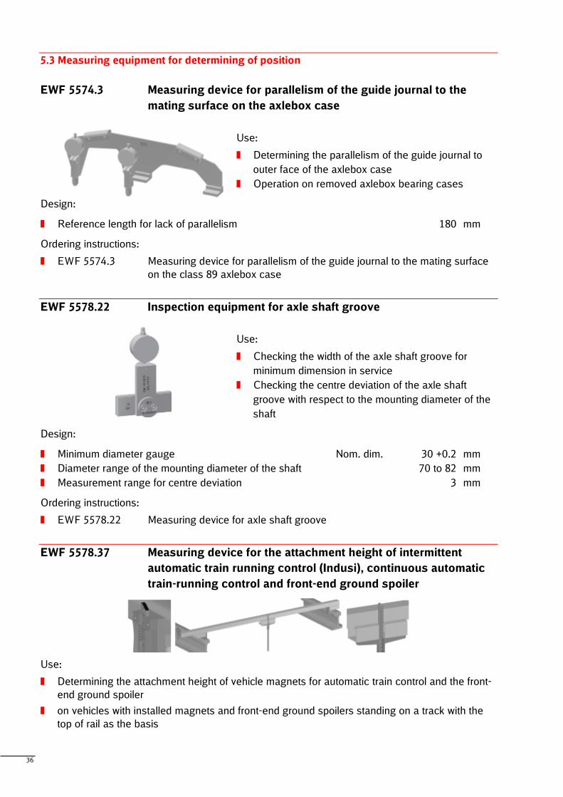
EWF 5573.105/1 Measuring device for the lateral clearances of the jigger pins on
freight wagons
Use:
Determining the lateral clearances C and d and a1 and a2 between the jigger pins on freight
wagons
Calliper operation with depositing edges on the freight wagon floor for safe handling by one
operator
Design:
Measuring range for the lateral clearances C and d 2,300 to 2,340 mm
Measuring range for the lateral clearances a1 and a2 2,250 to 2,290 mm
Ordering instructions:
EWF 5573.105/1 Measuring device for the lateral clearances of the jigger pins on freight
wagons
EWF 5573.105/2 Measuring device for minimum repair dimensions of the jigger
pins on freight wagons
Use:
Determining the minimum repair dimensions of the
jigger pins on freight wagons
Depth calliper operation for the undercut values a
and b on the outside and inside of the wagon
Design:
Measurement range 0 to 11 mm
Ordering instructions:
EWF 5573.105/2 Measuring device for minimum repair dimensions of the jigger pins on
freight wagons
35
EWF 5573.601 Measuring device for the flange thickness, height of the flange,
qR dimension and tyre/wheel rim thickness
Use:
Determining the functional dimensions flange
thickness e (Sd), height of the flange h (Sh), qR
dimension and tyre/wheel rim thickness Rd
Operation on installed and removed monobloc
wheels, tyres or wheels with tyres
The measurement basis is the outer rim face
Design:
Distance of the measuring circle plane from the inner rim face 70 mm
Flange thickness measurement range e (Sd) 20 to 40 mm
Height of the flange measurement range h (Sh) 20 to 40 mm
qR dimension measurement range 0 to 13 mm
Wheel rim thickness measurement range (Rd) 20 to 70 mm
Cross-reference to other measuring equipment:
EWF 5573.77/1 Measuring device for flange thickness, height of the flange and qR
dimension
EWF 5573.77/2 Measuring device for flange thickness, height and qR dimension with
bracket
Ordering instructions:
EWF 5573.601 Measuring device for the flange thickness, height, qR dimension and
tyre/wheel rim thickness
the requested design and the measuring range should be declared
additional
Special designs
The following listing contains general examples for customizable dimensions of the standard
measuring devices:
faces or shapes for measuring, referencing or examining can be customized to special
applications
nominal and limiting dimensions or measuring ranges can be extended, reduced or relocated
adjustment ranges or collision shapes can be changed or reduced
scales can be speced with a special resolution or a digital display
Note
36
5.3 Measuring equipment for determining of position
EWF 5574.3 Measuring device for parallelism of the guide journal to the
mating surface on the axlebox case
Use:
Determining the parallelism of the guide journal to
outer face of the axlebox case
Operation on removed axlebox bearing cases
Design:
Reference length for lack of parallelism 180 mm
Ordering instructions:
EWF 5574.3 Measuring device for parallelism of the guide journal to the mating surface
on the class 89 axlebox case
EWF 5578.22 Inspection equipment for axle shaft groove
Use:
Checking the width of the axle shaft groove for
minimum dimension in service
Checking the centre deviation of the axle shaft
groove with respect to the mounting diameter of the
shaft
Design:
Minimum diameter gauge Nom. dim. 30 +0.2 mm
Diameter range of the mounting diameter of the shaft 70 to 82 mm
Measurement range for centre deviation 3 mm
Ordering instructions:
EWF 5578.22 Measuring device for axle shaft groove
EWF 5578.37 Measuring device for the attachment height of intermittent
automatic train running control (Indusi), continuous automatic
train-running control and front-end ground spoiler
Use:
Determining the attachment height of vehicle magnets for automatic train control and the front-
end ground spoiler
on vehicles with installed magnets and front-end ground spoilers standing on a track with the
top of rail as the basis
37
Design:
Gauge 1,420 to 1,490 mm
Measurement range attachment height continuous automatic train-running control and
front-end ground spoiler above top of rail (centre of track) 100 to 285 mm
Measurement range attachment height intermittent automatic train running control/Indusi
above top of rail (300 mm outside of the track) 135 to 175 mm
Cross-reference to other measuring equipment:
EWF 5578.38 Measuring device for the attachment height of intermittent automatic train
running control (Indusi)
EWF 5563.56 Mounting template for Indusi magnet
Ordering instructions:
EWF 5578.37 Measuring device for the attachment height of intermittent automatic train
running control (Indusi), continuous automatic train-running control and
front-end ground spoiler
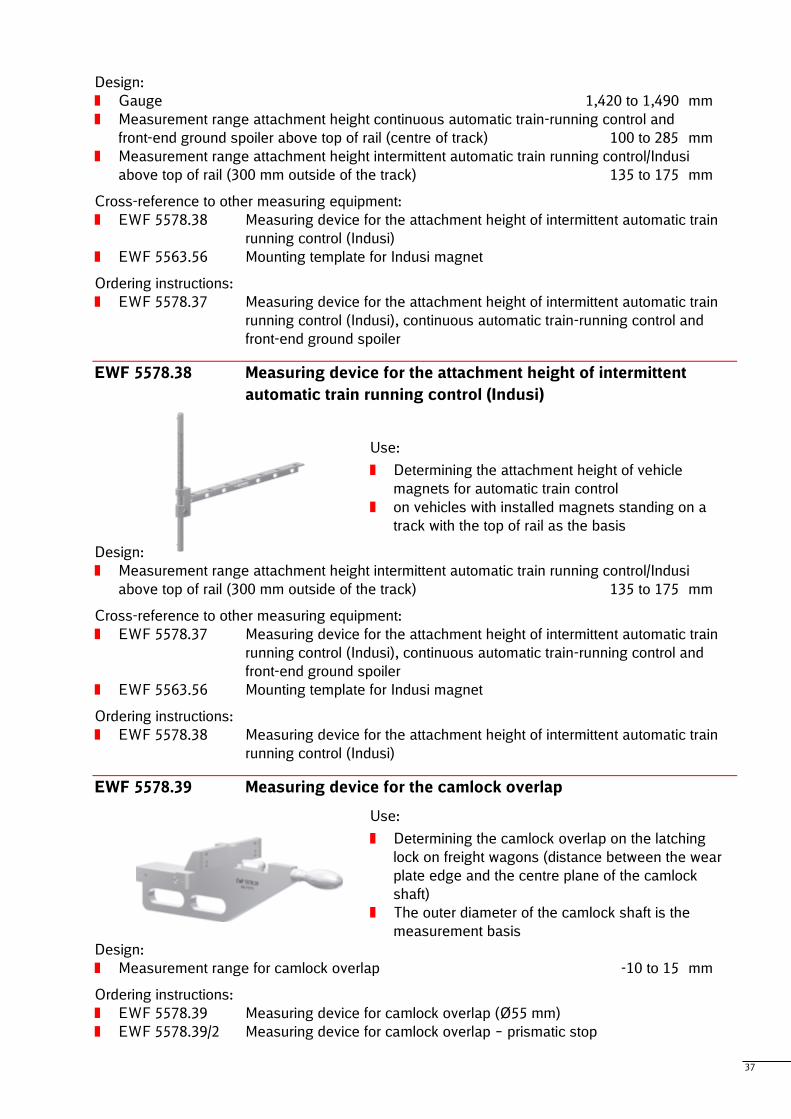
EWF 5578.38 Measuring device for the attachment height of intermittent
automatic train running control (Indusi)
Use:
Determining the attachment height of vehicle
magnets for automatic train control
on vehicles with installed magnets standing on a
track with the top of rail as the basis
Design:
Measurement range attachment height intermittent automatic train running control/Indusi
above top of rail (300 mm outside of the track) 135 to 175 mm
Cross-reference to other measuring equipment:
EWF 5578.37 Measuring device for the attachment height of intermittent automatic train
running control (Indusi), continuous automatic train-running control and
front-end ground spoiler
EWF 5563.56 Mounting template for Indusi magnet
Ordering instructions:
EWF 5578.38 Measuring device for the attachment height of intermittent automatic train
running control (Indusi)
EWF 5578.39 Measuring device for the camlock overlap
Use:
Determining the camlock overlap on the latching
lock on freight wagons (distance between the wear
plate edge and the centre plane of the camlock
shaft)
The outer diameter of the camlock shaft is the
measurement basis
Design:
Measurement range for camlock overlap -10 to 15 mm
Ordering instructions:
EWF 5578.39 Measuring device for camlock overlap (Ø55 mm)
EWF 5578.39/2 Measuring device for camlock overlap – prismatic stop
38
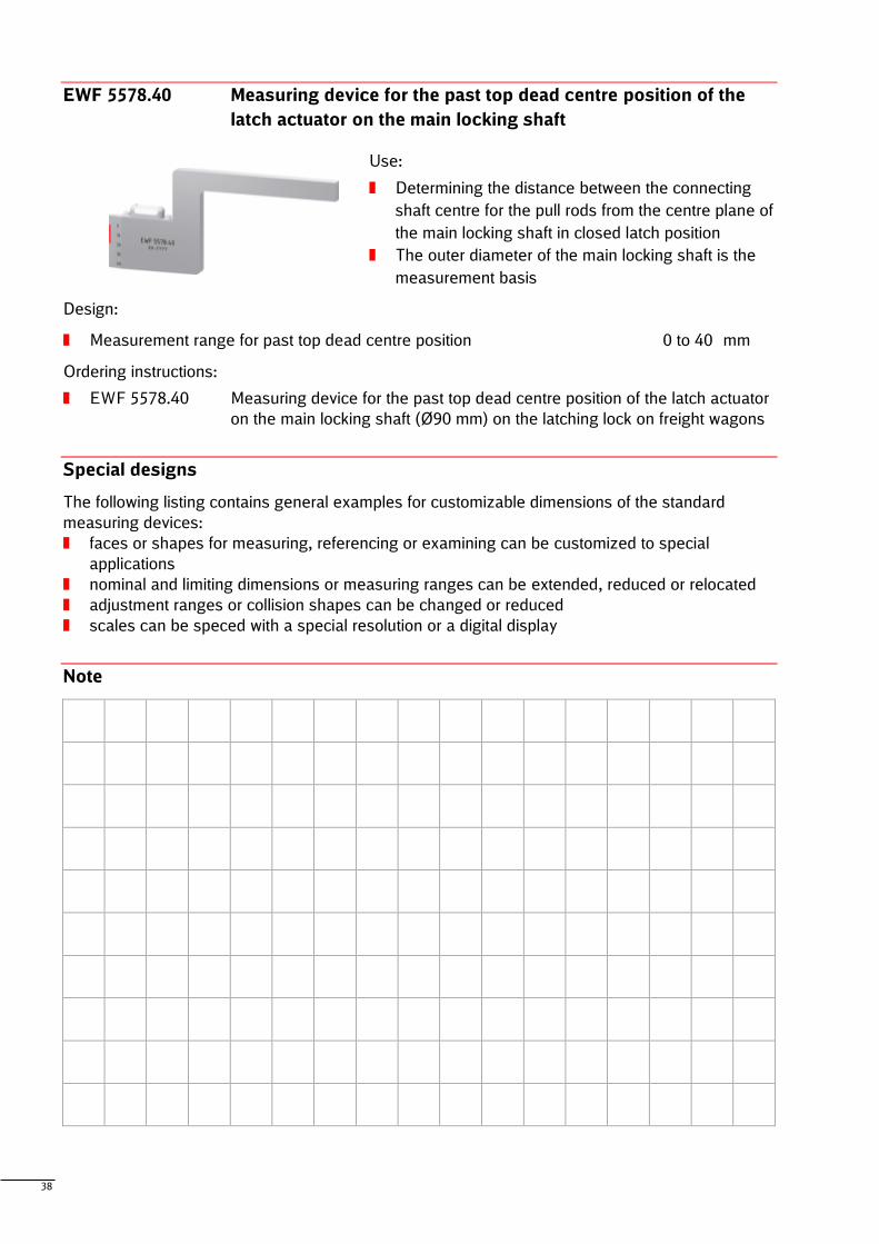
EWF 5578.40 Measuring device for the past top dead centre position of the
latch actuator on the main locking shaft
Use:
Determining the distance between the connecting
shaft centre for the pull rods from the centre plane of
the main locking shaft in closed latch position
The outer diameter of the main locking shaft is the
measurement basis
Design:
Measurement range for past top dead centre position 0 to 40 mm
Ordering instructions:
EWF 5578.40 Measuring device for the past top dead centre position of the latch actuator
on the main locking shaft (Ø90 mm) on the latching lock on freight wagons
Special designs
The following listing contains general examples for customizable dimensions of the standard
measuring devices:
faces or shapes for measuring, referencing or examining can be customized to special
applications
nominal and limiting dimensions or measuring ranges can be extended, reduced or relocated
adjustment ranges or collision shapes can be changed or reduced
scales can be speced with a special resolution or a digital display
Note
39
5.4 Other measuring equipment
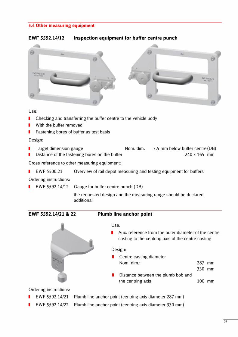
EWF 5592.14/12 Inspection equipment for buffer centre punch
Use:
Checking and transferring the buffer centre to the vehicle body
With the buffer removed
Fastening bores of buffer as test basis
Design:
Target dimension gauge Nom. dim. 7.5 mm below buffer centre (DB)
Distance of the fastening bores on the buffer 240 x 165 mm
Cross-reference to other measuring equipment:
EWF 5500.21 Overview of rail depot measuring and testing equipment for buffers
Ordering instructions:
EWF 5592.14/12 Gauge for buffer centre punch (DB)
the requested design and the measuring range should be declared
additional
EWF 5592.14/21 & 22 Plumb line anchor point
Use:
Aux. reference from the outer diameter of the centre
casting to the centring axis of the centre casting
Design:
Centre casting diameter
Nom. dim.: 287 mm
330 mm
Distance between the plumb bob and
the centring axis 100 mm
Ordering instructions:
EWF 5592.14/21 Plumb line anchor point (centring axis diameter 287 mm)
EWF 5592.14/22 Plumb line anchor point (centring axis diameter 330 mm)
40
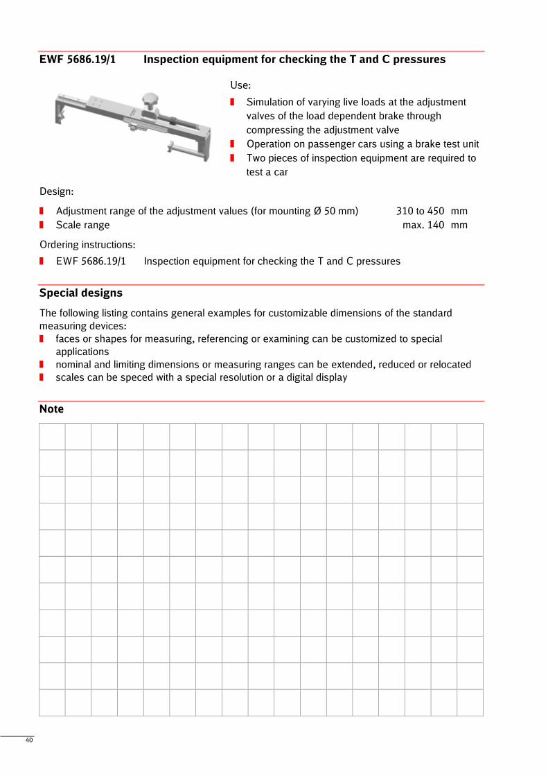
EWF 5686.19/1 Inspection equipment for checking the T and C pressures
Use:
Simulation of varying live loads at the adjustment
valves of the load dependent brake through
compressing the adjustment valve
Operation on passenger cars using a brake test unit
Two pieces of inspection equipment are required to
test a car
Design:
Adjustment range of the adjustment values (for mounting Ø 50 mm) 310 to 450 mm
Scale range max. 140 mm
Ordering instructions:
EWF 5686.19/1 Inspection equipment for checking the T and C pressures
Special designs
The following listing contains general examples for customizable dimensions of the standard
measuring devices:
faces or shapes for measuring, referencing or examining can be customized to special
applications
nominal and limiting dimensions or measuring ranges can be extended, reduced or relocated
scales can be speced with a special resolution or a digital display
Note
41
6 Measuring aid equipment and devices for dimension embodiment (EWF 5511 – EWF 5555)
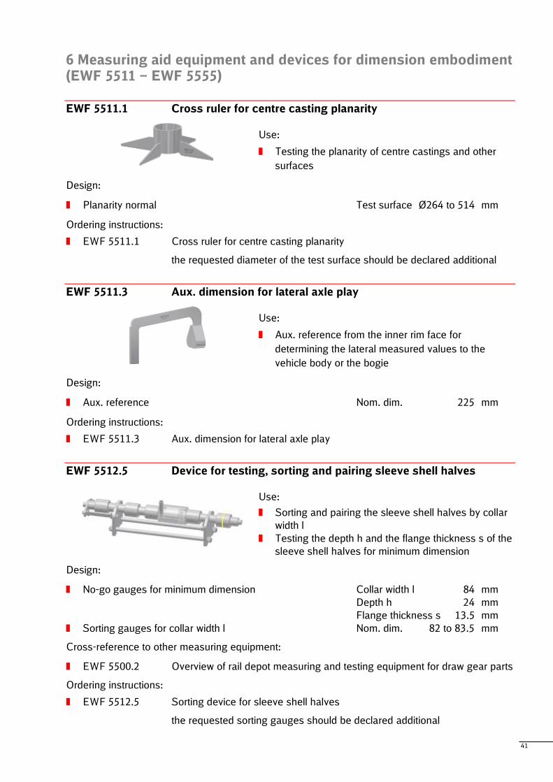
EWF 5511.1 Cross ruler for centre casting planarity
Use:
Testing the planarity of centre castings and other
surfaces
Design:
Planarity normal Test surface Ø264 to 514 mm
Ordering instructions:
EWF 5511.1 Cross ruler for centre casting planarity
the requested diameter of the test surface should be declared additional
EWF 5511.3 Aux. dimension for lateral axle play
Use:
Aux. reference from the inner rim face for
determining the lateral measured values to the
vehicle body or the bogie
Design:
Aux. reference Nom. dim. 225 mm
Ordering instructions:
EWF 5511.3 Aux. dimension for lateral axle play
EWF 5512.5 Device for testing, sorting and pairing sleeve shell halves
Use:
Sorting and pairing the sleeve shell halves by collar
width l
Testing the depth h and the flange thickness s of the
sleeve shell halves for minimum dimension
Design:
No-go gauges for minimum dimension Collar width l 84 mm
Depth h 24 mm
Flange thickness s 13.5 mm
Sorting gauges for collar width l Nom. dim. 82 to 83.5 mm
Cross-reference to other measuring equipment:
EWF 5500.2 Overview of rail depot measuring and testing equipment for draw gear parts
Ordering instructions:
EWF 5512.5 Sorting device for sleeve shell halves
the requested sorting gauges should be declared additional
42
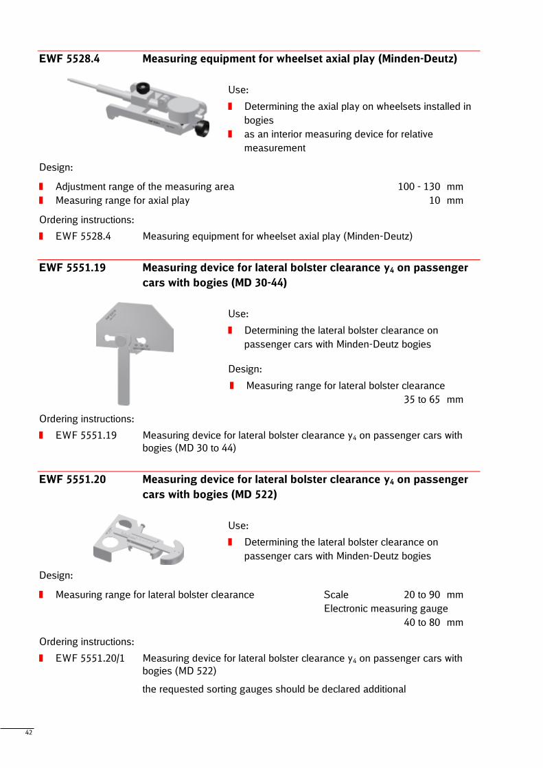
EWF 5528.4 Measuring equipment for wheelset axial play (Minden-Deutz)
Use:
Determining the axial play on wheelsets installed in
bogies
as an interior measuring device for relative
measurement
Design:
Adjustment range of the measuring area 100 - 130 mm
Measuring range for axial play 10 mm
Ordering instructions:
EWF 5528.4 Measuring equipment for wheelset axial play (Minden-Deutz)
EWF 5551.19 Measuring device for lateral bolster clearance y4 on passenger
cars with bogies (MD 30-44)
Use:
Determining the lateral bolster clearance on
passenger cars with Minden-Deutz bogies
Design:
Measuring range for lateral bolster clearance
35 to 65 mm
Ordering instructions:
EWF 5551.19 Measuring device for lateral bolster clearance y4 on passenger cars with
bogies (MD 30 to 44)
EWF 5551.20 Measuring device for lateral bolster clearance y4 on passenger
cars with bogies (MD 522)
Use:
Determining the lateral bolster clearance on
passenger cars with Minden-Deutz bogies
Design:
Measuring range for lateral bolster clearance Scale 20 to 90 mm
Electronic measuring gauge
40 to 80 mm
Ordering instructions:
EWF 5551.20/1 Measuring device for lateral bolster clearance y4 on passenger cars with
bogies (MD 522)
the requested sorting gauges should be declared additional
43
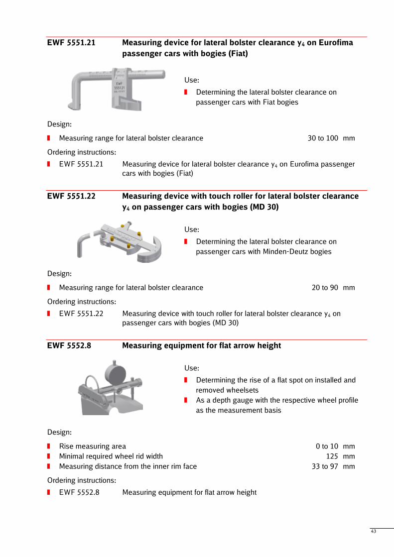
EWF 5551.21 Measuring device for lateral bolster clearance y4 on Eurofima
passenger cars with bogies (Fiat)
Use:
Determining the lateral bolster clearance on
passenger cars with Fiat bogies
Design:
Measuring range for lateral bolster clearance 30 to 100 mm
Ordering instructions:
EWF 5551.21 Measuring device for lateral bolster clearance y4 on Eurofima passenger
cars with bogies (Fiat)
EWF 5551.22 Measuring device with touch roller for lateral bolster clearance
y4 on passenger cars with bogies (MD 30)
Use:
Determining the lateral bolster clearance on
passenger cars with Minden-Deutz bogies
Design:
Measuring range for lateral bolster clearance 20 to 90 mm
Ordering instructions:
EWF 5551.22 Measuring device with touch roller for lateral bolster clearance y4 on
passenger cars with bogies (MD 30)
EWF 5552.8 Measuring equipment for flat arrow height
Use:
Determining the rise of a flat spot on installed and
removed wheelsets
As a depth gauge with the respective wheel profile
as the measurement basis
Design:
Rise measuring area 0 to 10 mm
Minimal required wheel rid width 125 mm
Measuring distance from the inner rim face 33 to 97 mm
Ordering instructions:
EWF 5552.8 Measuring equipment for flat arrow height
44
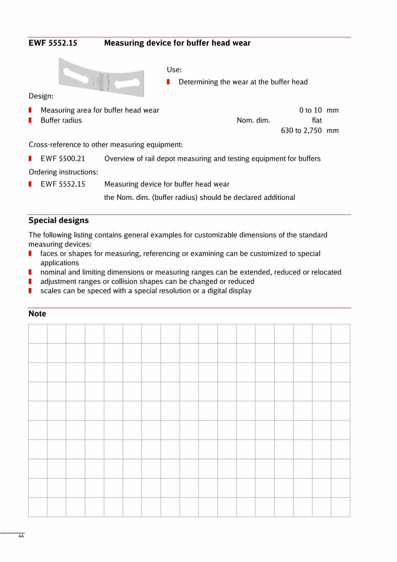
EWF 5552.15 Measuring device for buffer head wear
Use:
Determining the wear at the buffer head
Design:
Measuring area for buffer head wear 0 to 10 mm
Buffer radius Nom. dim. flat
630 to 2,750 mm
Cross-reference to other measuring equipment:
EWF 5500.21 Overview of rail depot measuring and testing equipment for buffers
Ordering instructions:
EWF 5552.15 Measuring device for buffer head wear
the Nom. dim. (buffer radius) should be declared additional
Special designs
The following listing contains general examples for customizable dimensions of the standard
measuring devices:
faces or shapes for measuring, referencing or examining can be customized to special
applications
nominal and limiting dimensions or measuring ranges can be extended, reduced or relocated
adjustment ranges or collision shapes can be changed or reduced
scales can be speced with a special resolution or a digital display
Note
45
7 Gauges (EWF 5561 – EWF 5568)
7.1 Gauges for inner dimensions
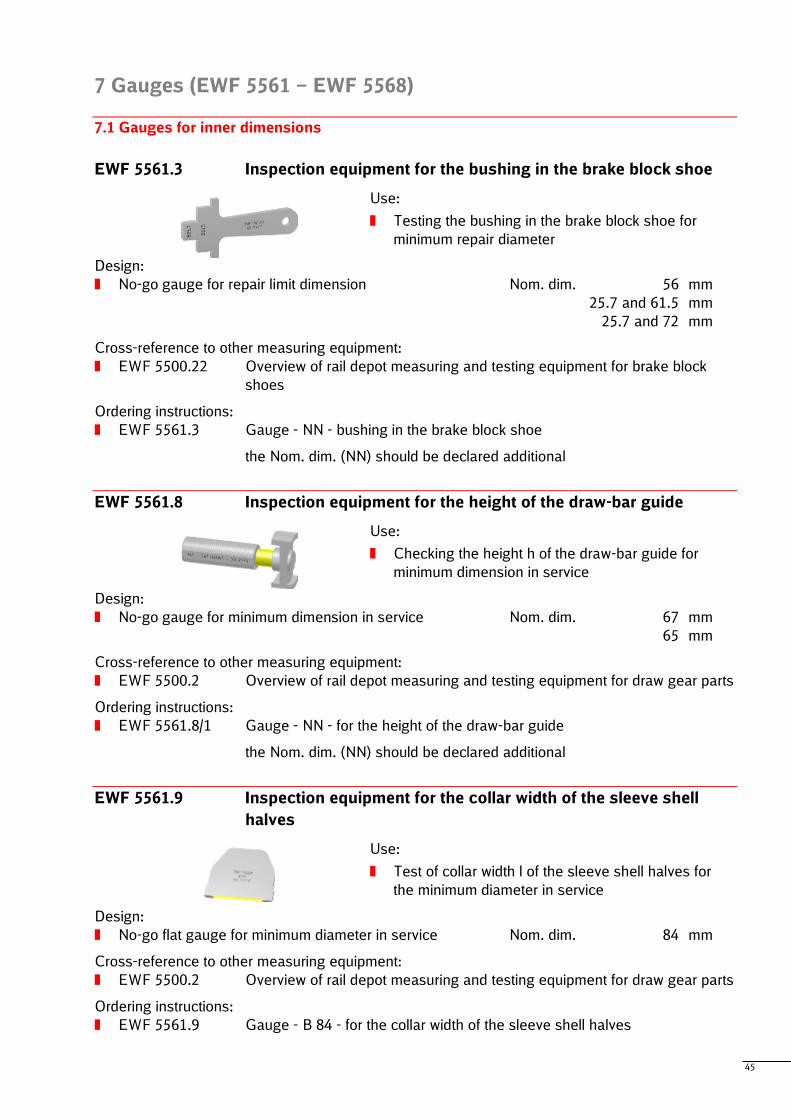
EWF 5561.3 Inspection equipment for the bushing in the brake block shoe
Use:
Testing the bushing in the brake block shoe for
minimum repair diameter
Design:
No-go gauge for repair limit dimension Nom. dim. 56 mm
25.7 and 61.5 mm
25.7 and 72 mm
Cross-reference to other measuring equipment:
EWF 5500.22 Overview of rail depot measuring and testing equipment for brake block
shoes
Ordering instructions:
EWF 5561.3 Gauge - NN - bushing in the brake block shoe
the Nom. dim. (NN) should be declared additional
EWF 5561.8 Inspection equipment for the height of the draw-bar guide
Use:
Checking the height h of the draw-bar guide for
minimum dimension in service
Design:
No-go gauge for minimum dimension in service Nom. dim. 67 mm
65 mm
Cross-reference to other measuring equipment:
EWF 5500.2 Overview of rail depot measuring and testing equipment for draw gear parts
Ordering instructions:
EWF 5561.8/1 Gauge - NN - for the height of the draw-bar guide
the Nom. dim. (NN) should be declared additional
EWF 5561.9 Inspection equipment for the collar width of the sleeve shell
halves
Use:
Test of collar width l of the sleeve shell halves for
the minimum diameter in service
Design:
No-go flat gauge for minimum diameter in service Nom. dim. 84 mm
Cross-reference to other measuring equipment:
EWF 5500.2 Overview of rail depot measuring and testing equipment for draw gear parts
Ordering instructions:
EWF 5561.9 Gauge - B 84 - for the collar width of the sleeve shell halves
46
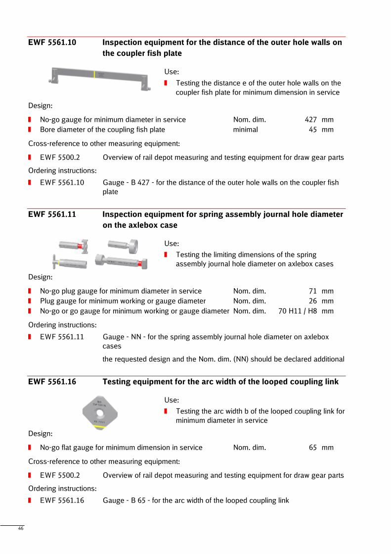
EWF 5561.10 Inspection equipment for the distance of the outer hole walls on
the coupler fish plate
Use:
Testing the distance e of the outer hole walls on the
coupler fish plate for minimum dimension in service
Design:
No-go gauge for minimum diameter in service Nom. dim. 427 mm
Bore diameter of the coupling fish plate minimal 45 mm
Cross-reference to other measuring equipment:
EWF 5500.2 Overview of rail depot measuring and testing equipment for draw gear parts
Ordering instructions:
EWF 5561.10 Gauge - B 427 - for the distance of the outer hole walls on the coupler fish
plate
EWF 5561.11 Inspection equipment for spring assembly journal hole diameter
on the axlebox case
Use:
Testing the limiting dimensions of the spring
assembly journal hole diameter on axlebox cases
Design:
No-go plug gauge for minimum diameter in service Nom. dim. 71 mm
Plug gauge for minimum working or gauge diameter Nom. dim. 26 mm
No-go or go gauge for minimum working or gauge diameter Nom. dim. 70 H11 / H8 mm
Ordering instructions:
EWF 5561.11 Gauge - NN - for the spring assembly journal hole diameter on axlebox
cases
the requested design and the Nom. dim. (NN) should be declared additional
EWF 5561.16 Testing equipment for the arc width of the looped coupling link
Use:
Testing the arc width b of the looped coupling link for
minimum diameter in service
Design:
No-go flat gauge for minimum dimension in service Nom. dim. 65 mm
Cross-reference to other measuring equipment:
EWF 5500.2 Overview of rail depot measuring and testing equipment for draw gear parts
Ordering instructions:
EWF 5561.16 Gauge - B 65 - for the arc width of the looped coupling link
47
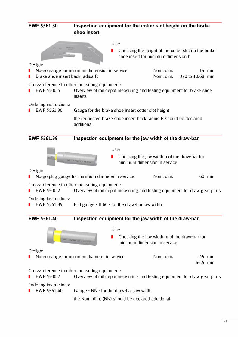
EWF 5561.30 Inspection equipment for the cotter slot height on the brake
shoe insert
Use:
Checking the height of the cotter slot on the brake
shoe insert for minimum dimension h
Design:
No-go gauge for minimum dimension in service Nom. dim. 14 mm
Brake shoe insert back radius R Nom. dim. 370 to 1,068 mm
Cross-reference to other measuring equipment:
EWF 5500.5 Overview of rail depot measuring and testing equipment for brake shoe
inserts
Ordering instructions:
EWF 5561.30 Gauge for the brake shoe insert cotter slot height
the requested brake shoe insert back radius R should be declared
additional
EWF 5561.39 Inspection equipment for the jaw width of the draw-bar
Use:
Checking the jaw width n of the draw-bar for
minimum dimension in service
Design:
No-go plug gauge for minimum diameter in service Nom. dim. 60 mm
Cross-reference to other measuring equipment:
EWF 5500.2 Overview of rail depot measuring and testing equipment for draw gear parts
Ordering instructions:
EWF 5561.39 Flat gauge - B 60 - for the draw-bar jaw width
EWF 5561.40 Inspection equipment for the jaw width of the draw-bar
Use:
Checking the jaw width m of the draw-bar for
minimum dimension in service
Design:
No-go gauge for minimum diameter in service Nom. dim. 45 mm
46,5 mm
Cross-reference to other measuring equipment:
EWF 5500.2 Overview of rail depot measuring and testing equipment for draw gear parts
Ordering instructions:
EWF 5561.40 Gauge - NN - for the draw-bar jaw width
the Nom. dim. (NN) should be declared additional
48
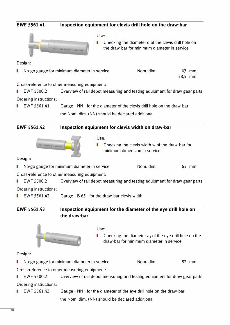
EWF 5561.41 Inspection equipment for clevis drill hole on the draw-bar
Use:
Checking the diameter d of the clevis drill hole on
the draw-bar for minimum diameter in service
Design:
No-go gauge for minimum diameter in service Nom. dim. 63 mm
58,5 mm
Cross-reference to other measuring equipment:
EWF 5500.2 Overview of rail depot measuring and testing equipment for draw gear parts
Ordering instructions:
EWF 5561.41 Gauge - NN - for the diameter of the clevis drill hole on the draw-bar
the Nom. dim. (NN) should be declared additional
EWF 5561.42 Inspection equipment for clevis width on draw-bar
Use:
Checking the clevis width w of the draw-bar for
minimum dimension in service
Design:
No-go gauge for minimum diameter in service Nom. dim. 65 mm
Cross-reference to other measuring equipment:
EWF 5500.2 Overview of rail depot measuring and testing equipment for draw gear parts
Ordering instructions:
EWF 5561.42 Gauge - B 65 - for the draw-bar clevis width
EWF 5561.43 Inspection equipment for the diameter of the eye drill hole on
the draw-bar
Use:
Checking the diameter a3 of the eye drill hole on the
draw-bar for minimum diameter in service
Design:
No-go gauge for minimum diameter in service Nom. dim. 82 mm
Cross-reference to other measuring equipment:
EWF 5500.2 Overview of rail depot measuring and testing equipment for draw gear parts
Ordering instructions:
EWF 5561.43 Gauge - NN - for the diameter of the eye drill hole on the draw-bar
the Nom. dim. (NN) should be declared additional
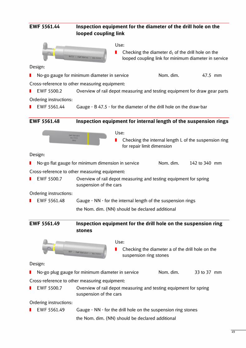
49
EWF 5561.44 Inspection equipment for the diameter of the drill hole on the
looped coupling link
Use:
Checking the diameter d1 of the drill hole on the
looped coupling link for minimum diameter in service
Design:
No-go gauge for minimum diameter in service Nom. dim. 47.5 mm
Cross-reference to other measuring equipment:
EWF 5500.2 Overview of rail depot measuring and testing equipment for draw gear parts
Ordering instructions:
EWF 5561.44 Gauge - B 47.5 - for the diameter of the drill hole on the draw-bar
EWF 5561.48 Inspection equipment for internal length of the suspension rings
Use:
Checking the internal length L of the suspension ring
for repair limit dimension
Design:
No-go flat gauge for minimum dimension in service Nom. dim. 142 to 340 mm
Cross-reference to other measuring equipment:
EWF 5500.7 Overview of rail depot measuring and testing equipment for spring
suspension of the cars
Ordering instructions:
EWF 5561.48 Gauge - NN - for the internal length of the suspension rings
the Nom. dim. (NN) should be declared additional
EWF 5561.49 Inspection equipment for the drill hole on the suspension ring
stones
Use:
Checking the diameter a of the drill hole on the
suspension ring stones
Design:
No-go plug gauge for minimum diameter in service Nom. dim. 33 to 37 mm
Cross-reference to other measuring equipment:
EWF 5500.7 Overview of rail depot measuring and testing equipment for spring
suspension of the cars
Ordering instructions:
EWF 5561.49 Gauge - NN - for the drill hole on the suspension ring stones
the Nom. dim. (NN) should be declared additional
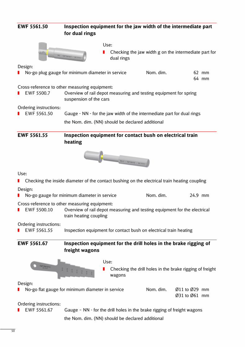
50
EWF 5561.50 Inspection equipment for the jaw width of the intermediate part
for dual rings
Use:
Checking the jaw width g on the intermediate part for
dual rings
Design:
No-go plug gauge for minimum diameter in service Nom. dim. 62 mm
64 mm
Cross-reference to other measuring equipment:
EWF 5500.7 Overview of rail depot measuring and testing equipment for spring
suspension of the cars
Ordering instructions:
EWF 5561.50 Gauge - NN - for the jaw width of the intermediate part for dual rings
the Nom. dim. (NN) should be declared additional
EWF 5561.55 Inspection equipment for contact bush on electrical train
heating
Use:
Checking the inside diameter of the contact bushing on the electrical train heating coupling
Design:
No-go gauge for minimum diameter in service Nom. dim. 24.9 mm
Cross-reference to other measuring equipment:
EWF 5500.10 Overview of rail depot measuring and testing equipment for the electrical
train heating coupling
Ordering instructions:
EWF 5561.55 Inspection equipment for contact bush on electrical train heating
EWF 5561.67 Inspection equipment for the drill holes in the brake rigging of
freight wagons
Use:
Checking the drill holes in the brake rigging of freight
wagons
Design:
No-go flat gauge for minimum diameter in service Nom. dim. Ø11 to Ø29 mm
Ø31 to Ø61 mm
Ordering instructions:
EWF 5561.67 Gauge – NN - for the drill holes in the brake rigging of freight wagons
the Nom. dim. (NN) should be declared additional
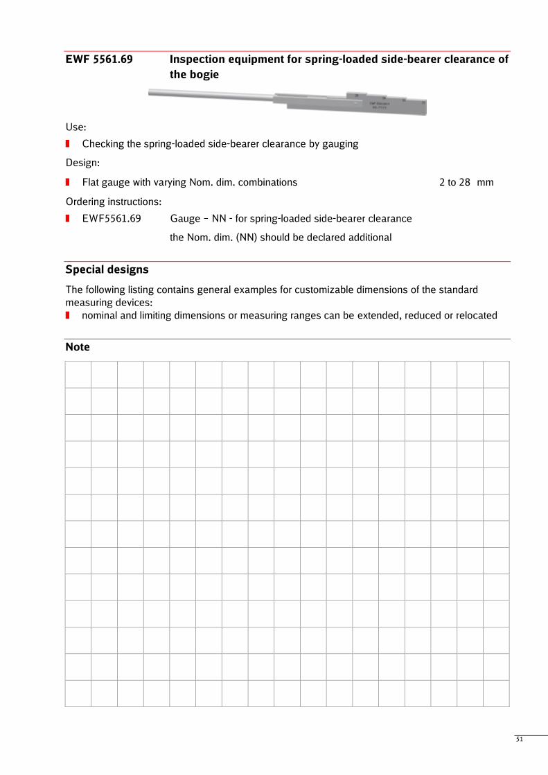
51
EWF 5561.69 Inspection equipment for spring-loaded side-bearer clearance of
the bogie
Use:
Checking the spring-loaded side-bearer clearance by gauging
Design:
Flat gauge with varying Nom. dim. combinations 2 to 28 mm
Ordering instructions:
EWF5561.69 Gauge – NN - for spring-loaded side-bearer clearance
the Nom. dim. (NN) should be declared additional
Special designs
The following listing contains general examples for customizable dimensions of the standard
measuring devices:
nominal and limiting dimensions or measuring ranges can be extended, reduced or relocated
Note
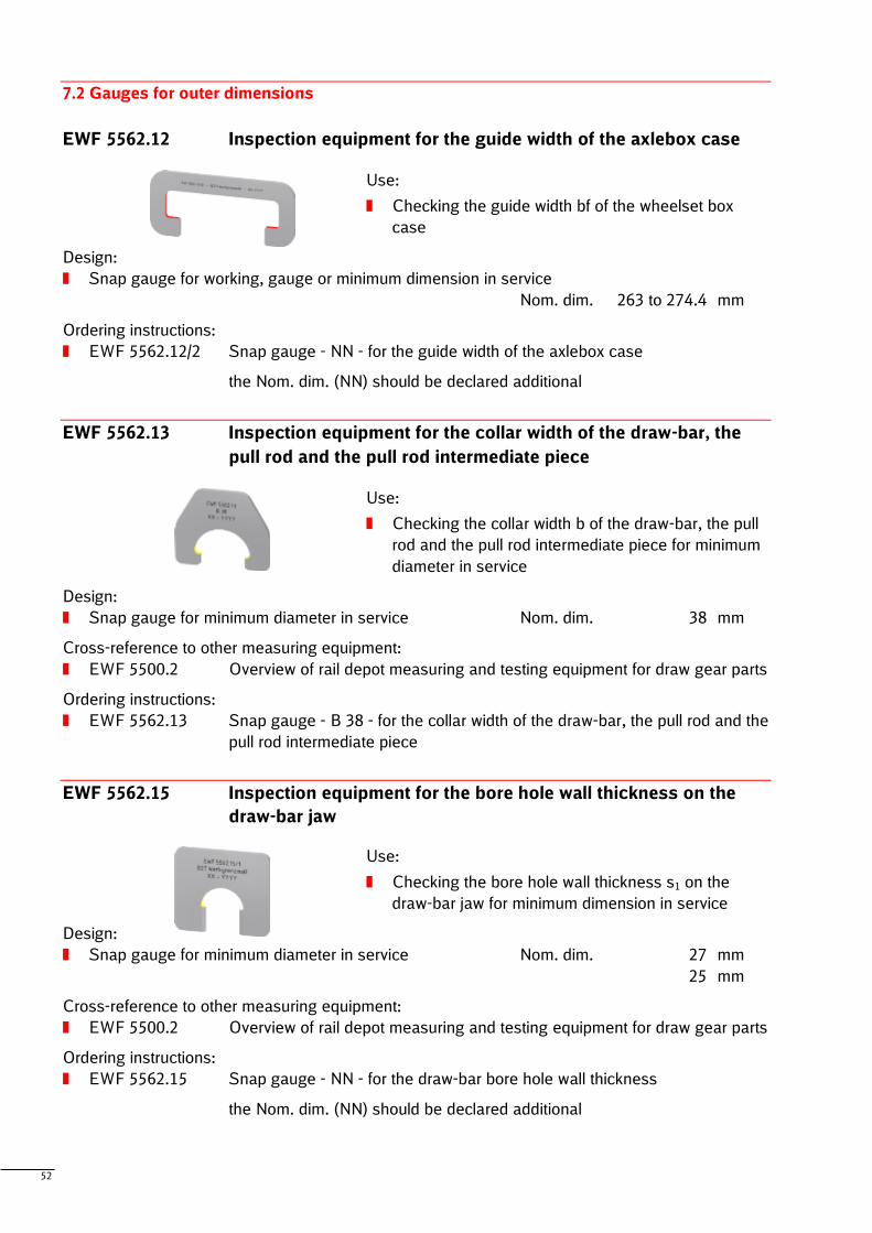
52
7.2 Gauges for outer dimensions
EWF 5562.12 Inspection equipment for the guide width of the axlebox case
Use:
Checking the guide width bf of the wheelset box
case
Design:
Snap gauge for working, gauge or minimum dimension in service
Nom. dim. 263 to 274.4 mm
Ordering instructions:
EWF 5562.12/2 Snap gauge - NN - for the guide width of the axlebox case
the Nom. dim. (NN) should be declared additional
EWF 5562.13 Inspection equipment for the collar width of the draw-bar, the
pull rod and the pull rod intermediate piece
Use:
Checking the collar width b of the draw-bar, the pull
rod and the pull rod intermediate piece for minimum
diameter in service
Design:
Snap gauge for minimum diameter in service Nom. dim. 38 mm
Cross-reference to other measuring equipment:
EWF 5500.2 Overview of rail depot measuring and testing equipment for draw gear parts
Ordering instructions:
EWF 5562.13 Snap gauge - B 38 - for the collar width of the draw-bar, the pull rod and the
pull rod intermediate piece
EWF 5562.15 Inspection equipment for the bore hole wall thickness on the
draw-bar jaw
Use:
Checking the bore hole wall thickness s1 on the
draw-bar jaw for minimum dimension in service
Design:
Snap gauge for minimum diameter in service Nom. dim. 27 mm
25 mm
Cross-reference to other measuring equipment:
EWF 5500.2 Overview of rail depot measuring and testing equipment for draw gear parts
Ordering instructions:
EWF 5562.15 Snap gauge - NN - for the draw-bar bore hole wall thickness
the Nom. dim. (NN) should be declared additional
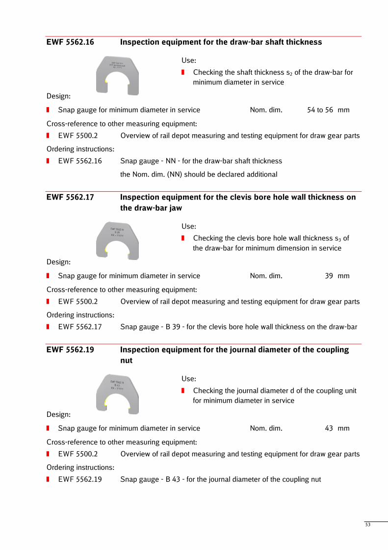
53
EWF 5562.16 Inspection equipment for the draw-bar shaft thickness
Use:
Checking the shaft thickness s2 of the draw-bar for
minimum diameter in service
Design:
Snap gauge for minimum diameter in service Nom. dim. 54 to 56 mm
Cross-reference to other measuring equipment:
EWF 5500.2 Overview of rail depot measuring and testing equipment for draw gear parts
Ordering instructions:
EWF 5562.16 Snap gauge - NN - for the draw-bar shaft thickness
the Nom. dim. (NN) should be declared additional
EWF 5562.17 Inspection equipment for the clevis bore hole wall thickness on
the draw-bar jaw
Use:
Checking the clevis bore hole wall thickness s3 of
the draw-bar for minimum dimension in service
Design:
Snap gauge for minimum diameter in service Nom. dim. 39 mm
Cross-reference to other measuring equipment:
EWF 5500.2 Overview of rail depot measuring and testing equipment for draw gear parts
Ordering instructions:
EWF 5562.17 Snap gauge - B 39 - for the clevis bore hole wall thickness on the draw-bar
EWF 5562.19 Inspection equipment for the journal diameter of the coupling
nut
Use:
Checking the journal diameter d of the coupling unit
for minimum diameter in service
Design:
Snap gauge for minimum diameter in service Nom. dim. 43 mm
Cross-reference to other measuring equipment:
EWF 5500.2 Overview of rail depot measuring and testing equipment for draw gear parts
Ordering instructions:
EWF 5562.19 Snap gauge - B 43 - for the journal diameter of the coupling nut
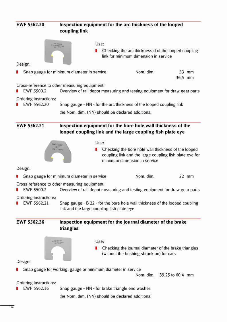
54
EWF 5562.20 Inspection equipment for the arc thickness of the looped
coupling link
Use:
Checking the arc thickness d of the looped coupling
link for minimum dimension in service
Design:
Snap gauge for minimum diameter in service Nom. dim. 33 mm
36.5 mm
Cross-reference to other measuring equipment:
EWF 5500.2 Overview of rail depot measuring and testing equipment for draw gear parts
Ordering instructions:
EWF 5562.20 Snap gauge - NN - for the arc thickness of the looped coupling link
the Nom. dim. (NN) should be declared additional
EWF 5562.21 Inspection equipment for the bore hole wall thickness of the
looped coupling link and the large coupling fish plate eye
Use:
Checking the bore hole wall thickness of the looped
coupling link and the large coupling fish plate eye for
minimum dimension in service
Design:
Snap gauge for minimum diameter in service Nom. dim. 22 mm
Cross-reference to other measuring equipment:
EWF 5500.2 Overview of rail depot measuring and testing equipment for draw gear parts
Ordering instructions:
EWF 5562.21 Snap gauge - B 22 - for the bore hole wall thickness of the looped coupling
link and the large coupling fish plate eye
EWF 5562.36 Inspection equipment for the journal diameter of the brake
triangles
Use:
Checking the journal diameter of the brake triangles
(without the bushing shrunk on) for cars
Design:
Snap gauge for working, gauge or minimum diameter in service
Nom. dim. 39.25 to 60.4 mm
Ordering instructions:
EWF 5562.36 Snap gauge - NN - for brake triangle end washer
the Nom. dim. (NN) should be declared additional
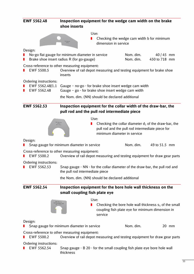
55
EWF 5562.48 Inspection equipment for the wedge cam width on the brake
shoe inserts
Use:
Checking the wedge cam width b for minimum
dimension in service
Design:
No-go flat gauge for minimum diameter in service Nom. dim. 40 / 45 mm
Brake shoe insert radius R (for go-gauge) Nom. dim. 450 to 718 mm
Cross-reference to other measuring equipment:
EWF 5500.5 Overview of rail depot measuring and testing equipment for brake shoe
inserts
Ordering instructions:
EWF 5562.48/1.1 Gauge – no-go - for brake shoe insert wedge cam width
EWF 5562.48 Gauge – go - for brake shoe insert wedge cam width
the Nom. dim. (NN) should be declared additional
EWF 5562.53 Inspection equipment for the collar width of the draw-bar, the
pull rod and the pull rod intermediate piece
Use:
Checking the collar diameter d2 of the draw-bar, the
pull rod and the pull rod intermediate piece for
minimum diameter in service
Design:
Snap gauge for minimum diameter in service Nom. dim. 49 to 51.5 mm
Cross-reference to other measuring equipment:
EWF 5500.2 Overview of rail depot measuring and testing equipment for draw gear parts
Ordering instructions:
EWF 5562.53 Snap gauge - NN - for the collar diameter of the draw-bar, the pull rod and
the pull rod intermediate piece
the Nom. dim. (NN) should be declared additional
EWF 5562.54 Inspection equipment for the bore hole wall thickness on the
small coupling fish plate eye
Use:
Checking the bore hole wall thickness s1 of the small
coupling fish plate eye for minimum dimension in
service
Design:
Snap gauge for minimum diameter in service Nom. dim. 20 mm
Cross-reference to other measuring equipment:
EWF 5500.2 Overview of rail depot measuring and testing equipment for draw gear parts
Ordering instructions:
EWF 5562.54 Snap gauge - B 20 - for the small coupling fish plate eye bore hole wall
thickness
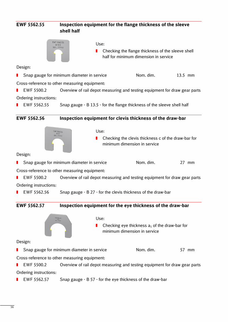
56
EWF 5562.55 Inspection equipment for the flange thickness of the sleeve
shell half
Use:
Checking the flange thickness of the sleeve shell
half for minimum dimension in service
Design:
Snap gauge for minimum diameter in service Nom. dim. 13.5 mm
Cross-reference to other measuring equipment:
EWF 5500.2 Overview of rail depot measuring and testing equipment for draw gear parts
Ordering instructions:
EWF 5562.55 Snap gauge - B 13.5 - for the flange thickness of the sleeve shell half
EWF 5562.56 Inspection equipment for clevis thickness of the draw-bar
Use:
Checking the clevis thickness c of the draw-bar for
minimum dimension in service
Design:
Snap gauge for minimum diameter in service Nom. dim. 27 mm
Cross-reference to other measuring equipment:
EWF 5500.2 Overview of rail depot measuring and testing equipment for draw gear parts
Ordering instructions:
EWF 5562.56 Snap gauge - B 27 - for the clevis thickness of the draw-bar
EWF 5562.57 Inspection equipment for the eye thickness of the draw-bar
Use:
Checking eye thickness a1 of the draw-bar for
minimum dimension in service
Design:
Snap gauge for minimum diameter in service Nom. dim. 57 mm
Cross-reference to other measuring equipment:
EWF 5500.2 Overview of rail depot measuring and testing equipment for draw gear parts
Ordering instructions:
EWF 5562.57 Snap gauge - B 57 - for the eye thickness of the draw-bar
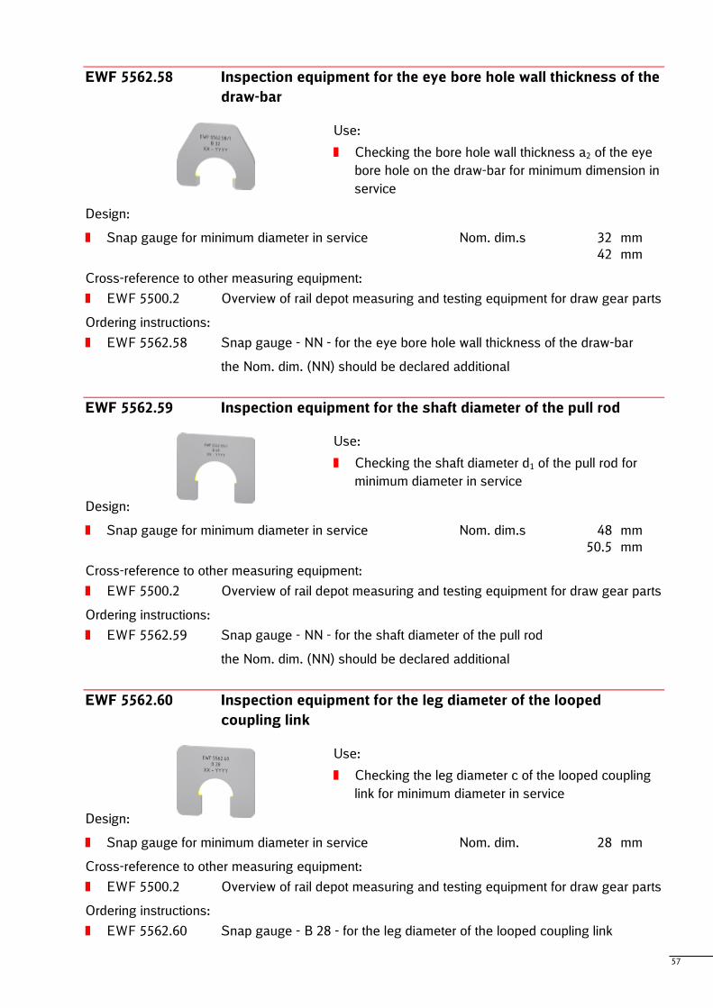
57
EWF 5562.58 Inspection equipment for the eye bore hole wall thickness of the
draw-bar
Use:
Checking the bore hole wall thickness a2 of the eye
bore hole on the draw-bar for minimum dimension in
service
Design:
Snap gauge for minimum diameter in service Nom. dim.s 32 mm
42 mm
Cross-reference to other measuring equipment:
EWF 5500.2 Overview of rail depot measuring and testing equipment for draw gear parts
Ordering instructions:
EWF 5562.58 Snap gauge - NN - for the eye bore hole wall thickness of the draw-bar
the Nom. dim. (NN) should be declared additional
EWF 5562.59 Inspection equipment for the shaft diameter of the pull rod
Use:
Checking the shaft diameter d1 of the pull rod for
minimum diameter in service
Design:
Snap gauge for minimum diameter in service Nom. dim.s 48 mm
50.5 mm
Cross-reference to other measuring equipment:
EWF 5500.2 Overview of rail depot measuring and testing equipment for draw gear parts
Ordering instructions:
EWF 5562.59 Snap gauge - NN - for the shaft diameter of the pull rod
the Nom. dim. (NN) should be declared additional
EWF 5562.60 Inspection equipment for the leg diameter of the looped
coupling link
Use:
Checking the leg diameter c of the looped coupling
link for minimum diameter in service
Design:
Snap gauge for minimum diameter in service Nom. dim. 28 mm
Cross-reference to other measuring equipment:
EWF 5500.2 Overview of rail depot measuring and testing equipment for draw gear parts
Ordering instructions:
EWF 5562.60 Snap gauge - B 28 - for the leg diameter of the looped coupling link
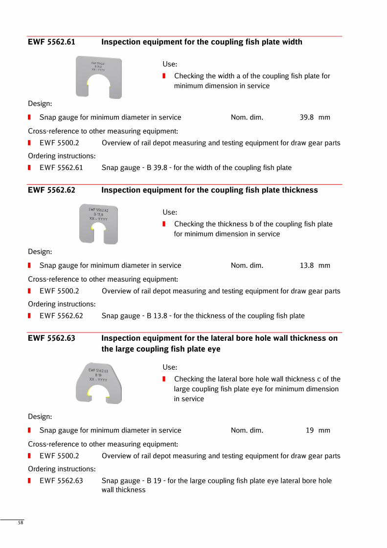
58
EWF 5562.61 Inspection equipment for the coupling fish plate width
Use:
Checking the width a of the coupling fish plate for
minimum dimension in service
Design:
Snap gauge for minimum diameter in service Nom. dim. 39.8 mm
Cross-reference to other measuring equipment:
EWF 5500.2 Overview of rail depot measuring and testing equipment for draw gear parts
Ordering instructions:
EWF 5562.61 Snap gauge - B 39.8 - for the width of the coupling fish plate
EWF 5562.62 Inspection equipment for the coupling fish plate thickness
Use:
Checking the thickness b of the coupling fish plate
for minimum dimension in service
Design:
Snap gauge for minimum diameter in service Nom. dim. 13.8 mm
Cross-reference to other measuring equipment:
EWF 5500.2 Overview of rail depot measuring and testing equipment for draw gear parts
Ordering instructions:
EWF 5562.62 Snap gauge - B 13.8 - for the thickness of the coupling fish plate
EWF 5562.63 Inspection equipment for the lateral bore hole wall thickness on
the large coupling fish plate eye
Use:
Checking the lateral bore hole wall thickness c of the
large coupling fish plate eye for minimum dimension
in service
Design:
Snap gauge for minimum diameter in service Nom. dim. 19 mm
Cross-reference to other measuring equipment:
EWF 5500.2 Overview of rail depot measuring and testing equipment for draw gear parts
Ordering instructions:
EWF 5562.63 Snap gauge - B 19 - for the large coupling fish plate eye lateral bore hole
wall thickness
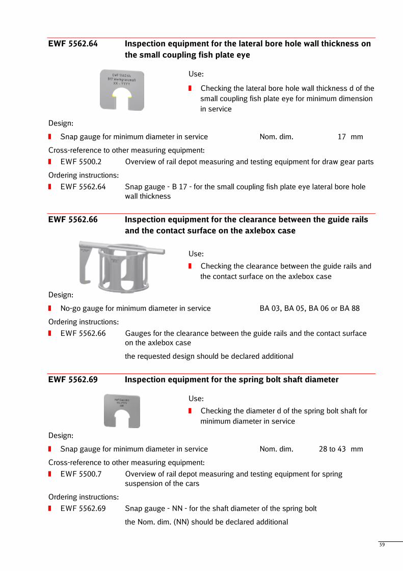
59
EWF 5562.64 Inspection equipment for the lateral bore hole wall thickness on
the small coupling fish plate eye
Use:
Checking the lateral bore hole wall thickness d of the
small coupling fish plate eye for minimum dimension
in service
Design:
Snap gauge for minimum diameter in service Nom. dim. 17 mm
Cross-reference to other measuring equipment:
EWF 5500.2 Overview of rail depot measuring and testing equipment for draw gear parts
Ordering instructions:
EWF 5562.64 Snap gauge - B 17 - for the small coupling fish plate eye lateral bore hole
wall thickness
EWF 5562.66 Inspection equipment for the clearance between the guide rails
and the contact surface on the axlebox case
Use:
Checking the clearance between the guide rails and
the contact surface on the axlebox case
Design:
No-go gauge for minimum diameter in service BA 03, BA 05, BA 06 or BA 88
Ordering instructions:
EWF 5562.66 Gauges for the clearance between the guide rails and the contact surface
on the axlebox case
the requested design should be declared additional
EWF 5562.69 Inspection equipment for the spring bolt shaft diameter
Use:
Checking the diameter d of the spring bolt shaft for
minimum diameter in service
Design:
Snap gauge for minimum diameter in service Nom. dim. 28 to 43 mm
Cross-reference to other measuring equipment:
EWF 5500.7 Overview of rail depot measuring and testing equipment for spring
suspension of the cars
Ordering instructions:
EWF 5562.69 Snap gauge - NN - for the shaft diameter of the spring bolt
the Nom. dim. (NN) should be declared additional
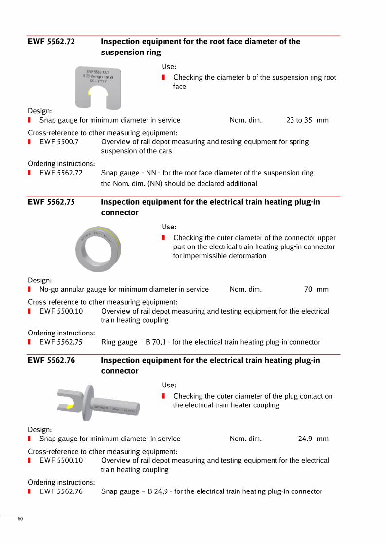
60
EWF 5562.72 Inspection equipment for the root face diameter of the
suspension ring
Use:
Checking the diameter b of the suspension ring root
face
Design:
Snap gauge for minimum diameter in service Nom. dim. 23 to 35 mm
Cross-reference to other measuring equipment:
EWF 5500.7 Overview of rail depot measuring and testing equipment for spring
suspension of the cars
Ordering instructions:
EWF 5562.72 Snap gauge - NN - for the root face diameter of the suspension ring
the Nom. dim. (NN) should be declared additional
EWF 5562.75 Inspection equipment for the electrical train heating plug-in
connector
Use:
Checking the outer diameter of the connector upper
part on the electrical train heating plug-in connector
for impermissible deformation
Design:
No-go annular gauge for minimum diameter in service Nom. dim. 70 mm
Cross-reference to other measuring equipment:
EWF 5500.10 Overview of rail depot measuring and testing equipment for the electrical
train heating coupling
Ordering instructions:
EWF 5562.75 Ring gauge – B 70,1 - for the electrical train heating plug-in connector
EWF 5562.76 Inspection equipment for the electrical train heating plug-in
connector
Use:
Checking the outer diameter of the plug contact on
the electrical train heater coupling
Design:
Snap gauge for minimum diameter in service Nom. dim. 24.9 mm
Cross-reference to other measuring equipment:
EWF 5500.10 Overview of rail depot measuring and testing equipment for the electrical
train heating coupling
Ordering instructions:
EWF 5562.76 Snap gauge – B 24,9 - for the electrical train heating plug-in connector
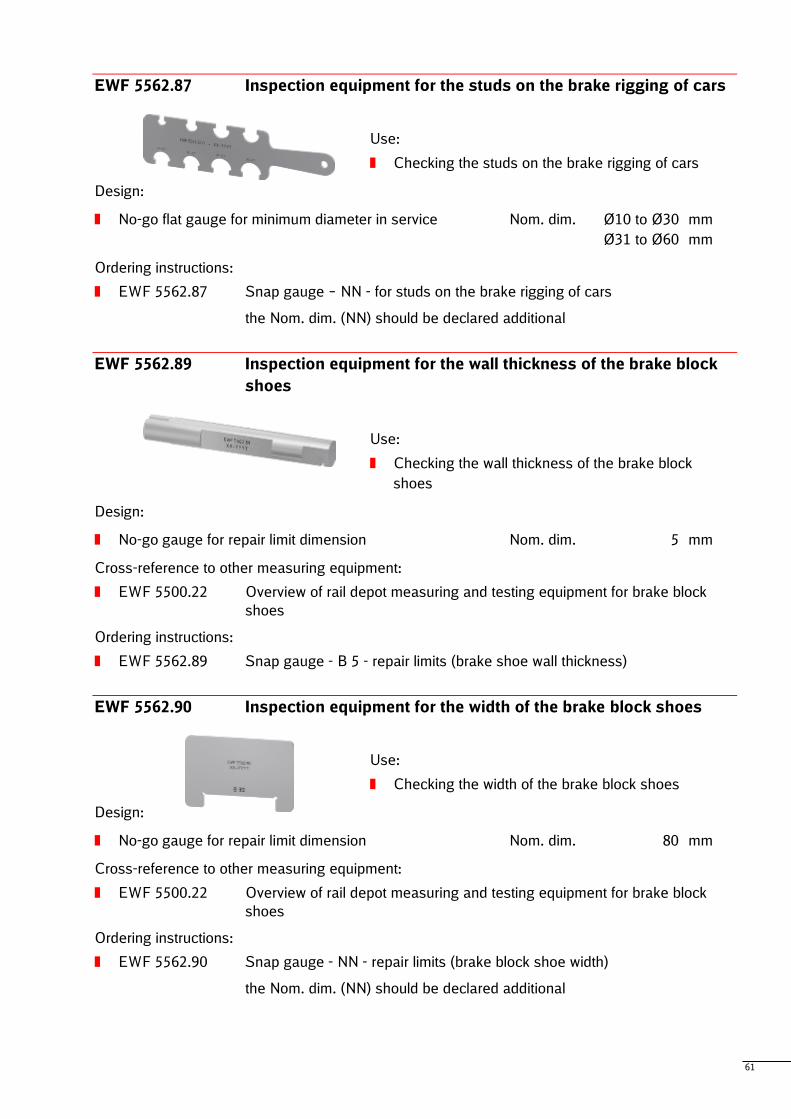
61
EWF 5562.87 Inspection equipment for the studs on the brake rigging of cars
Use:
Checking the studs on the brake rigging of cars
Design:
No-go flat gauge for minimum diameter in service Nom. dim. Ø10 to Ø30 mm
Ø31 to Ø60 mm
Ordering instructions:
EWF 5562.87 Snap gauge – NN - for studs on the brake rigging of cars
the Nom. dim. (NN) should be declared additional
EWF 5562.89 Inspection equipment for the wall thickness of the brake block
shoes
Use:
Checking the wall thickness of the brake block
shoes
Design:
No-go gauge for repair limit dimension Nom. dim. 5 mm
Cross-reference to other measuring equipment:
EWF 5500.22 Overview of rail depot measuring and testing equipment for brake block
shoes
Ordering instructions:
EWF 5562.89 Snap gauge - B 5 - repair limits (brake shoe wall thickness)
EWF 5562.90 Inspection equipment for the width of the brake block shoes
Use:
Checking the width of the brake block shoes
Design:
No-go gauge for repair limit dimension Nom. dim. 80 mm
Cross-reference to other measuring equipment:
EWF 5500.22 Overview of rail depot measuring and testing equipment for brake block
shoes
Ordering instructions:
EWF 5562.90 Snap gauge - NN - repair limits (brake block shoe width)
the Nom. dim. (NN) should be declared additional
62
Special designs
The following listing contains general examples for customizable dimensions of the standard
measuring devices:
nominal and limiting dimensions or measuring ranges can be extended, reduced or relocated
Note
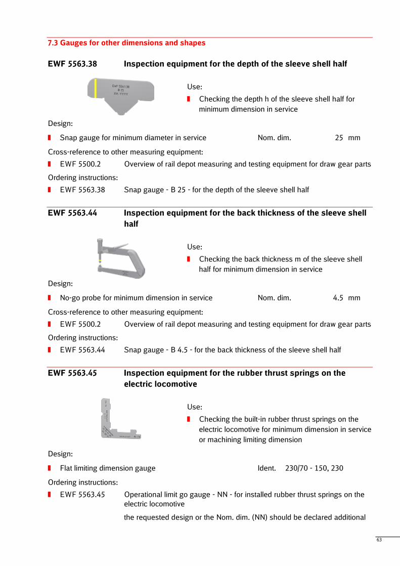
63
7.3 Gauges for other dimensions and shapes
EWF 5563.38 Inspection equipment for the depth of the sleeve shell half
Use:
Checking the depth h of the sleeve shell half for
minimum dimension in service
Design:
Snap gauge for minimum diameter in service Nom. dim. 25 mm
Cross-reference to other measuring equipment:
EWF 5500.2 Overview of rail depot measuring and testing equipment for draw gear parts
Ordering instructions:
EWF 5563.38 Snap gauge - B 25 - for the depth of the sleeve shell half
EWF 5563.44 Inspection equipment for the back thickness of the sleeve shell
half
Use:
Checking the back thickness m of the sleeve shell
half for minimum dimension in service
Design:
No-go probe for minimum dimension in service Nom. dim. 4.5 mm
Cross-reference to other measuring equipment:
EWF 5500.2 Overview of rail depot measuring and testing equipment for draw gear parts
Ordering instructions:
EWF 5563.44 Snap gauge - B 4.5 - for the back thickness of the sleeve shell half
EWF 5563.45 Inspection equipment for the rubber thrust springs on the
electric locomotive
Use:
Checking the built-in rubber thrust springs on the
electric locomotive for minimum dimension in service
or machining limiting dimension
Design:
Flat limiting dimension gauge Ident. 230/70 - 150, 230
Ordering instructions:
EWF 5563.45 Operational limit go gauge - NN - for installed rubber thrust springs on the
electric locomotive
the requested design or the Nom. dim. (NN) should be declared additional
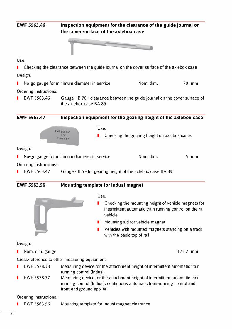
64
EWF 5563.46 Inspection equipment for the clearance of the guide journal on
the cover surface of the axlebox case
Use:
Checking the clearance between the guide journal on the cover surface of the axlebox case
Design:
No-go gauge for minimum diameter in service Nom. dim. 70 mm
Ordering instructions:
EWF 5563.46 Gauge - B 70 - clearance between the guide journal on the cover surface of
the axlebox case BA 89
EWF 5563.47 Inspection equipment for the gearing height of the axlebox case
Use:
Checking the gearing height on axlebox cases
Design:
No-go gauge for minimum diameter in service Nom. dim. 5 mm
Ordering instructions:
EWF 5563.47 Gauge - B 5 - for gearing height of the axlebox case BA 89
EWF 5563.56 Mounting template for Indusi magnet
Use:
Checking the mounting height of vehicle magnets for
intermittent automatic train running control on the rail
vehicle
Mounting aid for vehicle magnet
Vehicles with mounted magnets standing on a track
with the basic top of rail
Design:
Nom. dim. gauge 175.2 mm
Cross-reference to other measuring equipment:
EWF 5578.38 Measuring device for the attachment height of intermittent automatic train
running control (Indusi)
EWF 5578.37 Measuring device for the attachment height of intermittent automatic train
running control (Indusi), continuous automatic train-running control and
front-end ground spoiler
Ordering instructions:
EWF 5563.56 Mounting template for Indusi magnet clearance
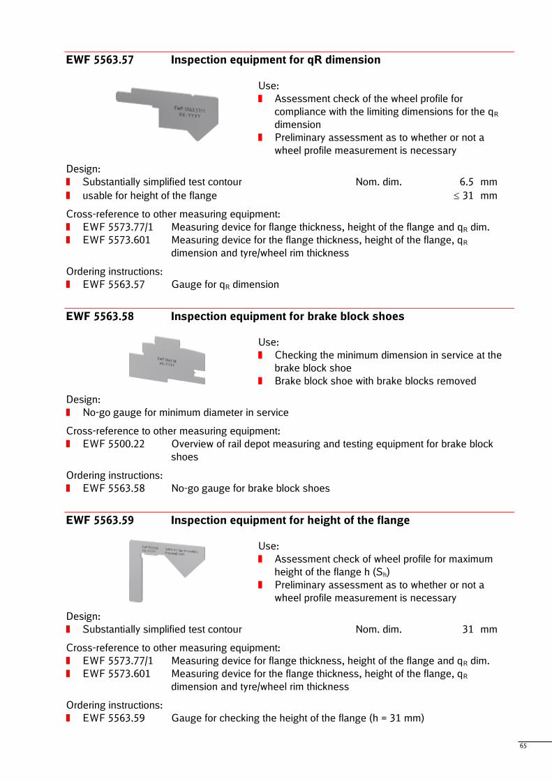
65
EWF 5563.57 Inspection equipment for qR dimension
Use:
Assessment check of the wheel profile for
compliance with the limiting dimensions for the qR
dimension
Preliminary assessment as to whether or not a
wheel profile measurement is necessary
Design:
Substantially simplified test contour Nom. dim. 6.5 mm
usable for height of the flange 31 mm
Cross-reference to other measuring equipment:
EWF 5573.77/1 Measuring device for flange thickness, height of the flange and qR dim.
EWF 5573.601 Measuring device for the flange thickness, height of the flange, qR
dimension and tyre/wheel rim thickness
Ordering instructions:
EWF 5563.57 Gauge for qR dimension
EWF 5563.58 Inspection equipment for brake block shoes
Use:
Checking the minimum dimension in service at the
brake block shoe
Brake block shoe with brake blocks removed
Design:
No-go gauge for minimum diameter in service
Cross-reference to other measuring equipment:
EWF 5500.22 Overview of rail depot measuring and testing equipment for brake block
shoes
Ordering instructions:
EWF 5563.58 No-go gauge for brake block shoes
EWF 5563.59 Inspection equipment for height of the flange
Use:
Assessment check of wheel profile for maximum
height of the flange h (Sh)
Preliminary assessment as to whether or not a
wheel profile measurement is necessary
Design:
Substantially simplified test contour Nom. dim. 31 mm
Cross-reference to other measuring equipment:
EWF 5573.77/1 Measuring device for flange thickness, height of the flange and qR dim.
EWF 5573.601 Measuring device for the flange thickness, height of the flange, qR
dimension and tyre/wheel rim thickness
Ordering instructions:
EWF 5563.59 Gauge for checking the height of the flange (h = 31 mm)
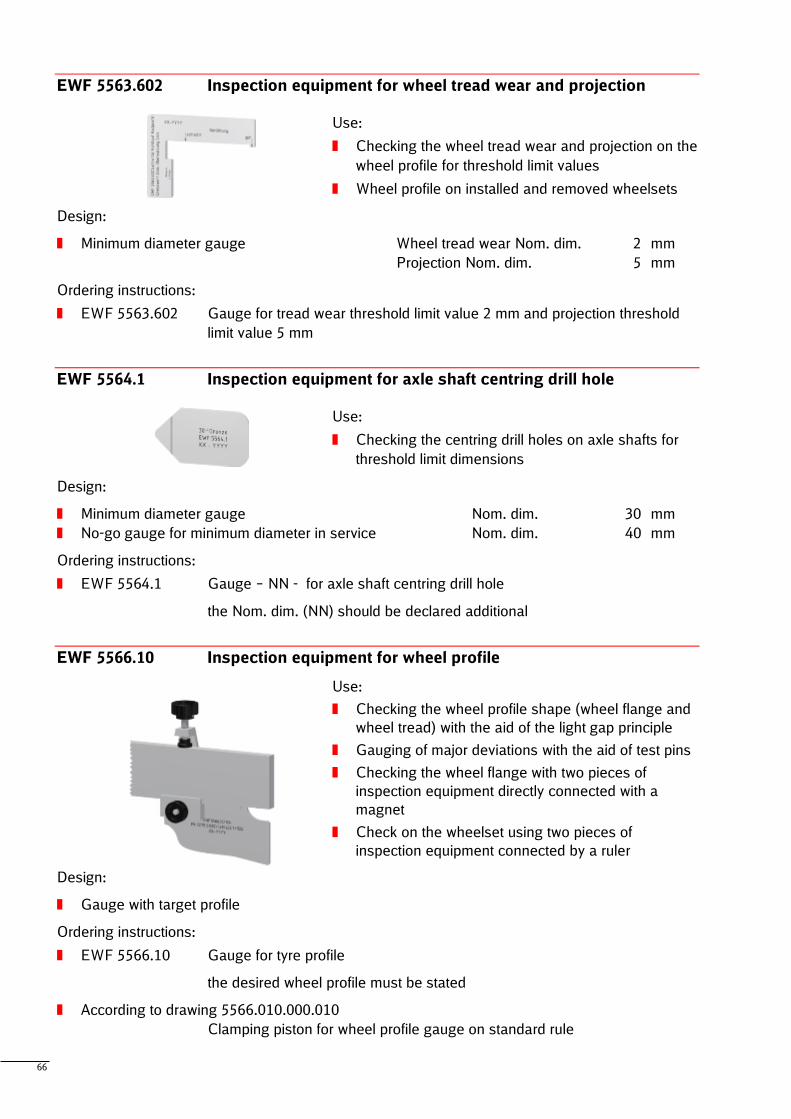
66
EWF 5563.602 Inspection equipment for wheel tread wear and projection
Use:
Checking the wheel tread wear and projection on the
wheel profile for threshold limit values
Wheel profile on installed and removed wheelsets
Design:
Minimum diameter gauge Wheel tread wear Nom. dim. 2 mm
Projection Nom. dim. 5 mm
Ordering instructions:
EWF 5563.602 Gauge for tread wear threshold limit value 2 mm and projection threshold
limit value 5 mm
EWF 5564.1 Inspection equipment for axle shaft centring drill hole
Use:
Checking the centring drill holes on axle shafts for
threshold limit dimensions
Design:
Minimum diameter gauge Nom. dim. 30 mm
No-go gauge for minimum diameter in service Nom. dim. 40 mm
Ordering instructions:
EWF 5564.1 Gauge – NN - for axle shaft centring drill hole
the Nom. dim. (NN) should be declared additional
EWF 5566.10 Inspection equipment for wheel profile
Use:
Checking the wheel profile shape (wheel flange and
wheel tread) with the aid of the light gap principle
Gauging of major deviations with the aid of test pins
Checking the wheel flange with two pieces of
inspection equipment directly connected with a
magnet
Check on the wheelset using two pieces of
inspection equipment connected by a ruler
Design:
Gauge with target profile
Ordering instructions:
EWF 5566.10 Gauge for tyre profile
the desired wheel profile must be stated
According to drawing 5566.010.000.010
Clamping piston for wheel profile gauge on standard rule
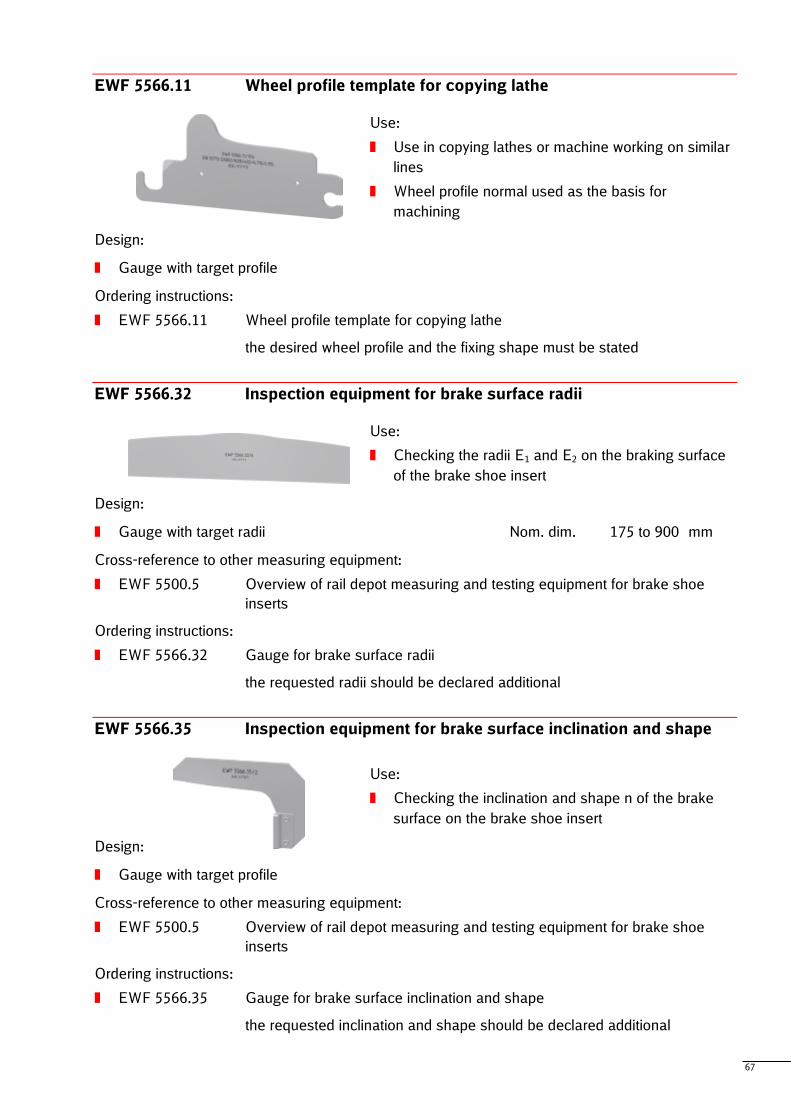
67
EWF 5566.11 Wheel profile template for copying lathe
Use:
Use in copying lathes or machine working on similar
lines
Wheel profile normal used as the basis for
machining
Design:
Gauge with target profile
Ordering instructions:
EWF 5566.11 Wheel profile template for copying lathe
the desired wheel profile and the fixing shape must be stated
EWF 5566.32 Inspection equipment for brake surface radii
Use:
Checking the radii E1 and E2 on the braking surface
of the brake shoe insert
Design:
Gauge with target radii Nom. dim. 175 to 900 mm
Cross-reference to other measuring equipment:
EWF 5500.5 Overview of rail depot measuring and testing equipment for brake shoe
inserts
Ordering instructions:
EWF 5566.32 Gauge for brake surface radii
the requested radii should be declared additional
EWF 5566.35 Inspection equipment for brake surface inclination and shape
Use:
Checking the inclination and shape n of the brake
surface on the brake shoe insert
Design:
Gauge with target profile
Cross-reference to other measuring equipment:
EWF 5500.5 Overview of rail depot measuring and testing equipment for brake shoe
inserts
Ordering instructions:
EWF 5566.35 Gauge for brake surface inclination and shape
the requested inclination and shape should be declared additional
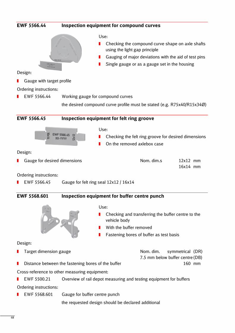
68
EWF 5566.44 Inspection equipment for compound curves
Use:
Checking the compound curve shape on axle shafts
using the light gap principle
Gauging of major deviations with the aid of test pins
Single gauge or as a gauge set in the housing
Design:
Gauge with target profile
Ordering instructions:
EWF 5566.44 Working gauge for compound curves
the desired compound curve profile must be stated (e.g. R75x40/R15x34Ø)
EWF 5566.45 Inspection equipment for felt ring groove
Use:
Checking the felt ring groove for desired dimensions
On the removed axlebox case
Design:
Gauge for desired dimensions Nom. dim.s 12x12 mm
16x14 mm
Ordering instructions:
EWF 5566.45 Gauge for felt ring seal 12x12 / 16x14
EWF 5568.601 Inspection equipment for buffer centre punch
Use:
Checking and transferring the buffer centre to the
vehicle body
With the buffer removed
Fastening bores of buffer as test basis
Design:
Target dimension gauge Nom. dim. symmetrical (DR)
7.5 mm below buffer centre (DB)
Distance between the fastening bores of the buffer 160 mm
Cross-reference to other measuring equipment:
EWF 5500.21 Overview of rail depot measuring and testing equipment for buffers
Ordering instructions:
EWF 5568.601 Gauge for buffer centre punch
the requested design should be declared additional
69
Special designs
The following listing contains general examples for customizable dimensions of the standard
measuring devices:
faces or shapes for measuring, referencing or examining can be customized to special
applications
nominal and limiting dimensions or measuring ranges can be extended, reduced or relocated
Note
70
8 Appendix
8.1 Technical notes
The present catalog doesn’t make claims of being complete, but it shows a representative cross section of the available measuring and inspection devices. According to the continuous engineering of measuring tasks and the development of vehicles, infrastructure, directives and manufacturer specifications, the range of rail depot measuring and testing equipment is growing steadily.
Accordingly the most important rail depot measuring and testing equipment is listed. This will be completed by new products, developed on the basis of current requirements.
Therefore the catalog can give a small impression of available rail depot measuring and testing equipment only. It should encourage you asking the DB Systemtechnik for your special requests.
All listed rail depot measuring and testing equipment and its components were developed and manufactured accordingly to German and European standards. It reflects the state of the art and the devices are robust, durable and easy to handle.
8.2 Index of EWF–number
EWF → Seite
5500.2 ................... 8 5500.5 ................. 10 5500.7 ................. 10 5500.10 ............... 11 5500.21 ............... 11 5500.22 ............... 11 5511.1 ................. 41 5511.3 ................. 41 5512.5 ................. 41 5528.4 ................. 42 5551.19 ............... 42 5551.20 ............... 42 5551.21 ............... 43 5551.22 ............... 43 5552.8 ................. 43 5552.15 ............... 44 5561.3 ................. 45 5561.8 ................. 45 5561.9 ................. 45 5561.10 ............... 46 5561.11 ............... 46 5561.16 ............... 46 5561.30 ............... 47 5561.39 ............... 47 5561.40 ............... 47 5561.41 ............... 48 5561.42 ............... 48 5561.43 ............... 48 5561.44 ............... 49 5561.48 ............... 49 5561.49 ............... 49 5561.50 ............... 50 5561.55 ............... 50 5561.67 ............... 50 5561.69 ............... 51
EWF → Seite
5562.12 ............... 52 5562.13 ............... 52 5562.15 ............... 52 5562.16 ............... 53 5562.17 ............... 53 5562.19 ............... 53 5562.20 ............... 54 5562.21 ............... 54 5562.36 ............... 54 5562.48 ............... 55 5562.53 ............... 55 5562.54 ............... 55 5562.55 ............... 56 5562.56 ............... 56 5562.57 ............... 56 5562.58 ............... 57 5562.59 ............... 57 5562.60 ............... 57 5562.61 ............... 58 5562.62 ............... 58 5562.63 ............... 58 5562.64 ............... 59 5562.66 ............... 59 5562.69 ............... 59 5562.72 ............... 60 5562.75 ............... 60 5562.76 ............... 60 5562.87 ............... 61 5562.89 ............... 61 5562.90 ............... 61 5563.38 ............... 63 5563.44 ............... 63 5563.45 ............... 63 5563.46 ............... 64 5563.47 ............... 64
EWF → Seite
5563.56 ............... 64 5563.57 ............... 65 5563.58 ............... 65 5563.59 ............... 65 5563.602 ............. 66 5564.1 ................. 66 5566.10 ............... 66 5566.11 ............... 67 5566.32 ............... 67 5566.35 ............... 67 5566.44 ............... 68 5566.45 ............... 68 5568.601 ............. 68 5571.1 ................. 14 5571.2 ................. 14 5572.2 ................. 15 5572.3 ................. 15 5572.4 ................. 16 5572.19 ............... 16 5572.24 ............... 17 5572.26 ............... 17 5573.2 ................. 18 5573.2/2 .............. 18 5573.34 ............... 18 5573.57 ............... 19 5573.72/3 ............ 19 5573.76 ............... 20 5573.77/1 ............ 20 5573.77/2 ............ 21 5573.77/5 ............ 21 5573.78 ............... 12 5573.78/101 ......... 22 5573.78/102 ......... 22 5573.78/105 ......... 23 5573.78/106 ......... 23
EWF → Seite
5573.78/107 ......... 24 5573.78/130 ......... 24 5573.78/140 ......... 25 5573.78/201 ......... 25 5573.78/203 ......... 26 5573.78/204 ......... 26 5573.78/205 ......... 26 5573.78/220 ......... 27 5573.79 ............... 13 5573.79/104 ......... 28 5573.79/130 ......... 28 5573.79/180 ......... 29 5573.79/190 ......... 29 5573.79/201 ......... 30 5573.79/203 ......... 30 5573.79/204 ......... 31 5573.79/206 ......... 31 5573.80 ............... 32 5573.84 ............... 32 5573.85 ............... 33 5573.98 ............... 33 5573.104 ............. 33 5573.105/1........... 34 5573.105/2........... 34 5573.601 ............. 35 5574.3 ................. 36 5578.22 ............... 36 5578.37 ............... 36 5578.38 ............... 37 5578.39 ............... 37 5578.40 ............... 38 5592.14/12........... 39 5592.14/21 & 22 .. 39 5686.19/1 ............ 40
71
8.3 Keyword index
→ Seite
AR dimension .............................................. 14, 19 automatic train control ..................... 16, 36, 37, 64 axial play ......................................................... 42 axle play .......................................................... 41 axle shaft groove ............................................. 36 axlebox case ........................36, 46, 52, 59, 64, 68 axle-mounted brake disc .................................. 33 bearing play ..................................................... 33 brake block shoe ............................. 11, 45, 61, 65 brake rigging ............................................... 50, 61 brake shoe insert ............................ 10, 47, 55, 67 brake surface ................................................... 67 brake triangle ................................................... 54 buffer ............................. 11, 18, 19, 20, 39, 44, 68 camlock overlap ............................................... 37 centre casting ....................................... 26, 31, 41 centring drill hole .............................................. 66 Centring stud ................................................... 31 centring the wheels .......................................... 17 Centring unit .................................................... 26 compass .......................................................... 30 compound curve .............................................. 68 coupling fish plate ................. 8, 46, 54, 55, 58, 59 coupling nut .................................................. 8, 53 coupling spindle ................................................. 8 diagonal dimension ................... 12, 13, 22, 25, 30 distortion .......................................................... 30 draw gear .......................................................... 8 draw-bar ........ 8, 32, 45, 47, 48, 52, 53, 55, 56, 57 electrical train heating coupling ............. 11, 50, 60 felt ring groove ................................................. 68 flange gauge ............................................... 15, 19 flange thickness .............................. 19, 20, 21, 35 friction ring thickness ....................................... 33 height of the flange ......................... 20, 21, 35, 65 height of the side bearers ................................. 26 intermediate part for dual rings .................... 10, 50
→ Seite
jigger pin .......................................................... 34 latch actuator ................................................... 38 lateral bolster clearance .............................. 42, 43 looped coupling link..................... 8, 46, 49, 54, 57 measuring mark height ..................................... 18 past top dead centre ........................................ 38 Plumb line ........................................................ 39 pull rod .............................................. 8, 52, 55, 57 pull rod connecting part ...................................... 8 pull rod intermediate piece ...................... 8, 52, 55 qR dimension ................................... 20, 21, 35, 65 reference distance between centres ............ 24, 28 rubber thrust spring .......................................... 63 Scriber ............................................................. 25 side-bearer clearance ...................................... 51 sleeve shell halves ...................... 8, 41, 45, 56, 63 spring bolt ................................................... 10, 59 spring stud ....................................................... 33 suspension ring ............................... 10, 33, 49, 60 suspension ring stone ..................... 10, 17, 33, 49 suspension ring stone hanger .......................... 32 suspension trestle .... 12, 13, 23, 24, 26, 27, 28, 30 T and C pressures ........................................... 40 the reference distance between centres ........... 22 tram wheels ..................................................... 21 tyre and wheel rim thickness ............................ 15 tyre drill hole .................................................... 14 tyre/wheel rim thickness ................................... 35 wheel base distance .............................. 12, 13, 25 wheel diameter ................................................ 16 wheel profile..................................................... 66 Wheel profile .................................................... 67 wheel rim shell width ........................................ 18 wheel tread wear ......................................... 33, 66 wheelset bearing guide ............................... 29, 31 wheelset bracket friction pad ..... 12, 13, 22, 23, 24 wheelset mount side bearer pair ....................... 29

Published by
DB Systemtechnik GmbH Emilienstraße 45
D-09131 Chemnitz
Further information:Website: www.db-systemtechnik.com
E-Mail: [email protected]: Heidi Urban
Subject to change without noticeErrors and omissions excepted Last revised: November 2016