Embed Size (px)
Citation preview

HAL Id: tel-00003454https://tel.archives-ouvertes.fr/tel-00003454
Submitted on 1 Oct 2003
HAL is a multi-disciplinary open accessarchive for the deposit and dissemination of sci-entific research documents, whether they are pub-lished or not. The documents may come fromteaching and research institutions in France orabroad, or from public or private research centers.
L’archive ouverte pluridisciplinaire HAL, estdestinée au dépôt et à la diffusion de documentsscientifiques de niveau recherche, publiés ou non,émanant des établissements d’enseignement et derecherche français ou étrangers, des laboratoirespublics ou privés.
ANCHORAGE MECHANICS OF DIFFERENTTYPES OF ROOT SYSTEMS
Slobodan B. Mickovski
To cite this version:Slobodan B. Mickovski. ANCHORAGE MECHANICS OF DIFFERENT TYPES OF ROOT SYS-TEMS. Ecology, environment. University of Manchester, 2002. English. �tel-00003454�

ANCHORAGE MECHANICS OF DIFFERENT
TYPES OF ROOT SYSTEMS
A thesis submitted to the University of Manchester for the Degree of
Doctor of Philosophy in the faculty of Science and Engineering
Slobodan Bogdan Mickovski
School of Biological Sciences
Division of Integrative Biology
2002

2
LIST OF CONTENTS
LIST OF CONTENTS.......................................................................................................................................................2
LIST OF FIGURES ...........................................................................................................................................................4
LIST OF TABLES ..............................................................................................................................................................6
LIST OF PLATES ..............................................................................................................................................................6
ABSTRACT.........................................................................................................................................................................7
DECLARATION................................................................................................................................................................8
THE AUTHOR....................................................................................................................................................................8
ACKNOWLEDGEMENTS .............................................................................................................................................9
CHAPTER ONE: INTRODUCTION.........................................................................................................................11
1.1 BACKGROUND.......................................................................................................................................................... 111.1.1 Types of Root Systems ...................................................................................................................................111.1.2 Factors Influencing Root System Form................................................................................................121.1.3 Root System Anchorage ..........................................................................................................................13
1.2 LINES OF INVESTIGATION....................................................................................................................................... 151.2.1 Modelling the Uprooting Resistance of Bulbs..........................................................................................151.2.2 Overturning Resistance of Rigid Tap Roots..............................................................................................151.2.3 The Influence of Soil Compaction and Temperature on the Growth and Development of RootSystems in Two Pinus Species ...............................................................................................................................161.2.4 The Effect of Unidirectional Stem Flexing on Shoot and Root Morphology and Architecture inYoung Pinus sylvestris Trees .................................................................................................................................161.2.5 A Morphological and Mechanical Study of the Root Systems of Suppressed Crown Scots PinePinus sylvestris.........................................................................................................................................................171.2.6 Anchorage Mechanics and Asymmetry in the Root System of Macedonian Pine Pinus peuce(Gris.).........................................................................................................................................................................17
CHAPTER TWO: MODELLING THE UPROOTING RESISTANCE OF BULBS: THE EFFECTOF SHAPE, SIZE, DEPTH, AND SOIL TYPE.......................................................................................................19
2.1 INTRODUCTION.................................................................................................................................................. 192.2 MATERIALS AND METHODS......................................................................................................................... 21
2.2.1 Models .............................................................................................................................................................212.2.2 Soils..................................................................................................................................................................212.2.3 Mechanical Tests ...........................................................................................................................................222.2.4 The Investigations..........................................................................................................................................222.2.5 Anchorage Tests on Real Bulbs...................................................................................................................24
2.3 RESULTS................................................................................................................................................................ 272.3.1 Preliminary Tests...........................................................................................................................................272.3.2 Main Tests.......................................................................................................................................................282.3.3 Anchorage Tests on Real Bulbs...................................................................................................................33
2.4 DISCUSSION......................................................................................................................................................... 37
CHAPTER THREE: OVERTURNING RESISTANCE OF RIGID TAP ROOTS.......................................42
3.1 INTRODUCTION........................................................................................................................................................ 423.2 MATERIALS AND METHODS................................................................................................................................... 44
3.2.1 Models .............................................................................................................................................................443.2.2 Soils..................................................................................................................................................................443.2.3 Tests and Analyses.........................................................................................................................................44
3.3 RESULTS................................................................................................................................................................... 483.3.1 Main Tests.......................................................................................................................................................483.3.2 Mechanical Analysis and Scaling of Anchorage......................................................................................53
3.4 DISCUSSION.............................................................................................................................................................. 54

3
CHAPTER FOUR: THE INFLUENCE OF SOIL COMPACTION AND TEMPERATURE ONTHE GROWTH AND THE DEVELOPMENT OF ROOT SYSTEMS IN TWO PINUS SPECIES .......59
4.1 INTRODUCTION........................................................................................................................................................ 594.2 MATERIALS AND METHODS................................................................................................................................... 61
4.2.1 Seedlings.........................................................................................................................................................614.2.2 Soil ...................................................................................................................................................................614.2.3 Soil Preparation and Planting ....................................................................................................................614.2.4 Penetrometer Resistance..............................................................................................................................634.2.5 Root System Measurements..........................................................................................................................634.2.6 Statistical Methods........................................................................................................................................64
4.3 RESULTS................................................................................................................................................................... 644.3.2 Root System Architecture and Distribution ..............................................................................................654.3.3 Axial Root Elongation...................................................................................................................................684.3.4 Lateral Root Proliferation ...........................................................................................................................704.3.5 Radial Root Growth ......................................................................................................................................72
4.4 DISCUSSION.............................................................................................................................................................. 73
CHAPTER FIVE: THE EFFECT OF UNIDIRECTIONAL STEM FLEXING ON SHOOT ANDROOT MORPHOLOGY AND ARCHITECTURE IN YOUNG PINUS SYLVESTRIS TREES...............78
5.1 INTRODUCTION........................................................................................................................................................ 785.2 MATERIALS AND METHODS................................................................................................................................... 80
5.2.1 Seedlings.........................................................................................................................................................805.2.2 Measurements at the Start of the Investigation........................................................................................805.2.3 Planting , Flexing, and Growth Conditions..............................................................................................815.2.4 Resistance to Deflection...............................................................................................................................835.2.5 Measurements at Harvest .............................................................................................................................84
5.3 RESULTS................................................................................................................................................................... 865.3.1 Resistance to deflection................................................................................................................................865.3.2 Morphological changes................................................................................................................................875.3.3 Biomass distribution .....................................................................................................................................89Avg. dry weight [g]..................................................................................................................................................895.3.4 Mechanical properties of wood...................................................................................................................90
5.4 DISCUSSION.............................................................................................................................................................. 90
CHAPTER SIX: A MORPHOLOGICAL AND MECHANICAL STUDY OF THE ROOTSYSTEMS OF SUPPRESSED CROWN SCOTS PINE PINUS SYLVESTRIS ..............................................94
6.1 INTRODUCTION.................................................................................................................................................. 946.2 MATERIALS AND METHODS......................................................................................................................... 96
6.2.1 Site Details......................................................................................................................................................966.2.2 Selection and Extraction of the Study Trees..............................................................................................966.2.3 Preliminary Tests...........................................................................................................................................966.2.4 Overturning Tests ..........................................................................................................................................976.2.5 Root System Morphology and Architecture Measurements ...................................................................996.2.6 Soil Measurements ........................................................................................................................................996.2.7 Investigation of Root Distribution Relative to the Overturning Direction....................................... 1006.2.8 Investigation of Absolute Root Distribution........................................................................................... 1006.2.9 Investigation of Root Distribution Relative to Depth........................................................................... 1016.2.10 Statistical Methods................................................................................................................................... 101
6.3 RESULTS..............................................................................................................................................................1016.3.1 Preliminary Tests........................................................................................................................................ 1016.3.2 Anchorage Rigidity..................................................................................................................................... 1026.3.3 Overturning Tests ....................................................................................................................................... 1036.3.4 Root Anchorage .......................................................................................................................................... 1046.3.5 Root System Architecture .......................................................................................................................... 1056.3.6 Soil Conditions............................................................................................................................................ 108
6.4 DISCUSSION.......................................................................................................................................................109
CHAPTER SEVEN: ANCHORAGE MECHANICS AND ASYMMETRY IN THE ROOTSYSTEM OF MACEDONIAN PINE PINUS PEUCE (GRIS.) ........................................................................ 114
7.1 INTRODUCTION......................................................................................................................................................1147.2 MATERIALS AND METHODS.......................................................................................................................116
7.2.1 Site Details................................................................................................................................................... 116
4
7.2.2 Selection and Extraction of the Study Trees........................................................................................... 1167.2.3 Preliminary Tests........................................................................................................................................ 1177.2.4 Overturning Tests ....................................................................................................................................... 1177.2.5 Root System Morphology and Architecture Measurements ................................................................ 1177.2.6 Soil Measurements ..................................................................................................................................... 1187.2.7 Investigation of Root Distribution Relative to the Overturning Direction....................................... 1187.2.8 Investigation of Absolute Root Distribution........................................................................................... 1187.2.9 Investigation of Eccentricity and Aspect Ratio of Major Lateral Roots ........................................... 1197.2.10 Investigation of Root Distribution Relative to Depth......................................................................... 1197.2.11 Statistical Methods................................................................................................................................... 119
7.3. RESULTS .............................................................................................................................................................1207.3.1 Preliminary Tests........................................................................................................................................ 1207.3.2 Anchorage Rigidity..................................................................................................................................... 1207.3.3 Overturning Tests ....................................................................................................................................... 1217.3.4 Root System Architecture .......................................................................................................................... 1227.3.5 Eccentricity and Aspect Ratio of Lateral Roots .................................................................................... 1257.3.6 Soil Penetrometer Resistance................................................................................................................... 126
7.4. DISCUSSION...........................................................................................................................................................126
CHAPTER EIGHT: CONCLUDING REMARKS AND AREAS FOR FUTURE RESEARCH........... 134
REFERENCES:............................................................................................................................................................. 140
LIST OF FIGURES
FIGURE 2.1 The features of a typical bulb. .................................................................................. 19
FIGURE 2.2 The apparatus and method for uprooting model bulbs.................................................. 22
FIGURE 2.3 The uprooting resistance of six different shapes of bulb models.................................... 28
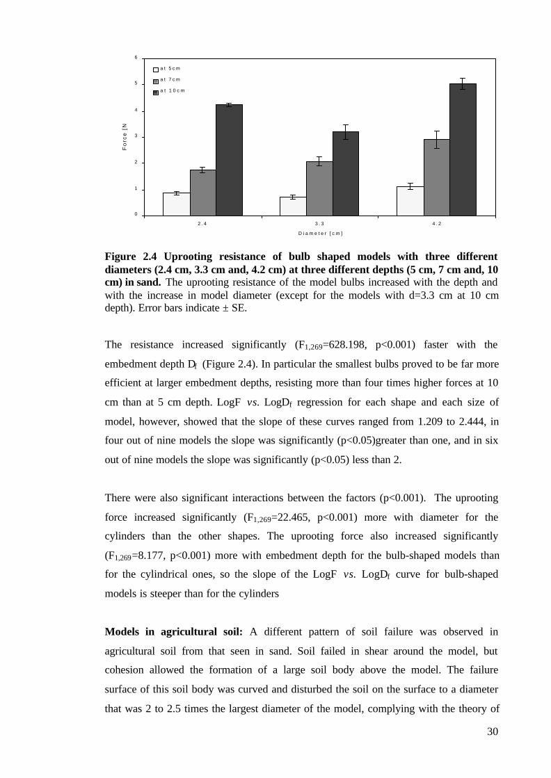
Figure 2.4 Uprooting resistance of bulb shaped models with three different diameters (2.4 cm, 3.3
cm and, 4.2 cm) at three different depths (5 cm, 7 cm and, 10 cm) in sand................................ 30
FIGURE 2.5 A comparison between uprooting resistance of the cylinder and bulb shaped models. ...... 32
FIGURE 2.6 Uprooting resistance of bulb shaped models with three different diameters (2.4 cm, 3.3
cm and, 4.2 cm) at three different depths (5 cm, 7 cm and, 10 cm) in agricultural soil................. 33
FIGURE 2.7 Average maximum uprooting resistance in a) garlic and b) onion.. ............................... 36
FIGURE 2.8 Patterns of soil failure in a) sand and b) agricultural soil. ............................................. 38
FIGURE 3.1 The apparatus for measuring the overturning resistance of model tap roots. ................... 46
FIGURE 3.2 Overturning resistance of tap root models of four different sizes (D1=4.2 mm,
D2=6.35mm, D3=8.50 mm, D4=12.70 mm) in three different depths (3 cm, 5 cm, and 7 cm) in
sand ................................................................................................................................ 49
FIGURE 3.3 Log-Log dependency between the overturning moment (M) and the embedment depth
(Df). ................................................................................................................................ 49
FIGURE 3.4 Log – Log dependency between the overturning moment (M) and the model diameter
(D).. ................................................................................................................................ 50
FIGURE 3.5 Overturning resistance of tap root models of four different sizes (D1=4.2 mm,
D2=6.35mm, D3=8.50 mm, D4=12.70 mm) in three different depths (3 cm, 5 cm, and 7 cm) in
agricultural soil. ................................................................................................................ 51
5
FIGURE 3.6 Log-Log dependency between the overturning moment (M) and the embedment depth
(Df). ................................................................................................................................ 52
FIGURE 3.7 Log – Log dependency between the overturning moment (M) and the model diameter
(D). ................................................................................................................................. 52
FIGURE 3.8 The mechanism of anchorage failure under horizontal overturning force (Hu) in a)
cohesionless and b) cohesive media. .................................................................................... 54
FIGURE 3.9 Two possible types of root failure under horizontal lateral loads (Hu).. .......................... 56
FIGURE 4.1 Pine seedlings planted in plastic containers (side and top view).................................... 62
FIGURE 4.2 Penetrometer resistance at four different soil depths (2.5 cm, 5 cm, 7.5 cm, and 10 cm)
for the three types of soil consistency (loose, semi-compact and, compact)............................... 64
FIGURE 4.3 Average maximum root axial length in both Pinus sylvestris and Pinus peuce seedlings
at the start and at the end of the experiment. ......................................................................... 67
FIGURE 4.4 Average number of major lateral roots in Pinus sylvestris and Pinus peuce seedlings at
the start and at the end of the experiment.............................................................................. 68
FIGURE 4.5 Average axial root growth rate of a) Pinus sylvestris and b) Pinus peuce seedlings
grown at three different temperatures (15°C, 20°C, and 25°C) and in three different soil
consistencies (loose, semi-compact and, compact)................................................................. 69
FIGURE 4.6 Average increase in the number of major lateral roots in a) Pinus sylvestris and b)
Pinus peuce at three different temperatures (15°C, 20°C and, 25°C) in three different
consistencies (loose, semi-compact and, compact).. ............................................................... 71
FIGURE 4.7 Average diameter of major lateral roots in Pinus sylvestris and Pinus peuce at the start
and at the end of the experiment.. ........................................................................................ 72
FIGURE 5.1 Division of the space around the stem into quadrants.. ................................................ 81
FIGURE 5.2 Top and side view of the planted seedlings and the flexing procedure. .......................... 82
FIGURE 5.3 Resistance to deflection in test and control P. sylvestris trees in three different
directions ......................................................................................................................... 87
FIGURE 6.1 a) Top view and b) side view of the winching apparatus and method used in this study. .. 98
FIGURE 6.2 Log-Log graph showing the relationship between the diameter at breast height (DBH)
of inner and outer trees and their maximum overturning moment (M). ................................... 104
FIGURE 6.3 Graph showing the relationship between the diameter at breast height (DBH) of inner
and outer trees in the stand and their root cross sectional area (CSA)...................................... 105
FIGURE 6.4 Polar plot of the mean centres of the root cross sectional area of each tree.. ................. 107
FIGURE 6.5 Graph showing the relationship between the asymmetry in the distribution of major
lateral root CSA (root asymmetry ratio) and the asymmetry in the overturning resistance
(anchorage asymmetry ratio) around the tree trunk. ............................................................. 108
FIGURE 6.6 Graph showing the relationship between the root cross sectional area (CSA) and the
soil shear strength in the three different soil horizons: 0-5cm, 5-10cm, and 10-15cm. .............. 109
FIGURE 7.1 Regression lines between Log DBH and log M for the Pinus peuce trees from the inner
and outer part of the stand in the Pelister National Park (MK). .............................................. 122

6
FIGURE 7.2 Regression lines between Log DBH and Log CSA for the Pinus peuce trees from the
inner and outer belt of the stand in the Pelister National Park (MK).. ..................................... 123
FIGURE 7.3 Average orientation of the centre of the root CSA (circular direction) plotted against
the magnitude of asymmetry (radial direction) for the Pinus peuce trees investigated. .............. 124
FIGURE 7.4 Regression between root asymmetry ratio and the anchorage asymmetry ratio.............. 125
FIGURE 7.5 Penetrometer resistance of the soil in Pelister National Park [MK] compared to the one
in the Jodrell Bank Arboretum [UK].................................................................................. 126
FIGURE 7.6 Average eccentricity in vertically eccentric lateral roots in Pinus peuce compared to the
one in Pinus sylvestris trees investigated in the Chapter Five of this thesis.. ............................ 131
LIST OF TABLES
TABLE 5.1. Differences in major lateral root CSA and in the number of major lateral roots in
test and control trees in planes parallel and perpendicular to flexing, before and after the
treatment......................................................................................................................... 89
TABLE 5.2. Average dry weight of the various constituents of investigated trees with the
average root:shoot ratio.. .................................................................................................. 89
TABLE 5.3. Average mechanical properties of stem and root wood in test and control trees......... 90
TABLE 6.1 The mean anchorage rigidity and the percentage of the root cross sectional area
mobilised in tension during each pull of the overturning tests. .......................................... 102
TABLE 7.1 Mean anchorage rigidity and distribution of the major lateral root CSA in four
different directions in the investigated Pinus peuce trees. ................................................. 121
LIST OF PLATES
PLATE 2.1. Uprooting of real bulbs – the apparatus .................................................................. 26
PLATE 2.2. Development of bulb form in garlic and onion......................................................... 35
PLATE 4.1 The morphology and architecture of one-year-old a) P. peuce and b) P. sylvestris
root system...................................................................................................................... 66
PLATE 6.1 The root system of an average 18-year-old P. sylvestris tree from inside the tree
stand at the University of Manchester Granada Arboretum in Jodrell Bank, Cheshire ......... 112
PLATE 7.1 Asymmetry in the distribution of major lateral roots around the trunk of P. peuce at
Pelister National Park, Macedonia ................................................................................... 129
7
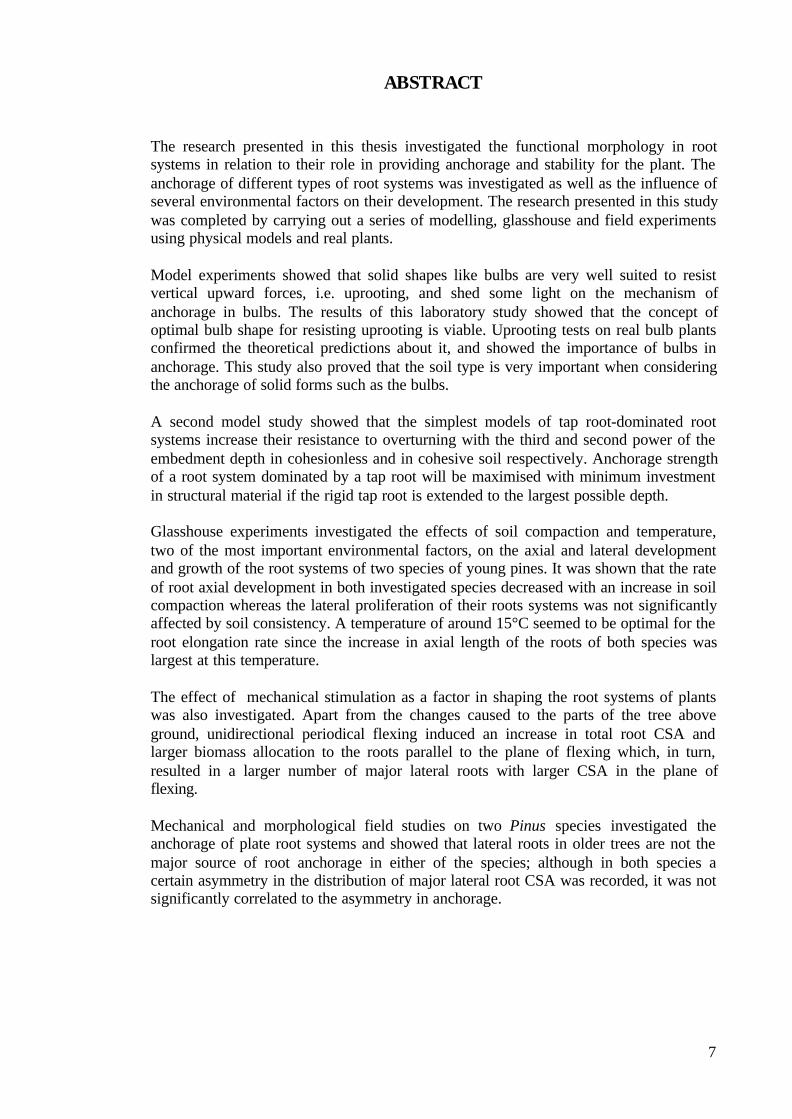
ABSTRACT
The research presented in this thesis investigated the functional morphology in rootsystems in relation to their role in providing anchorage and stability for the plant. Theanchorage of different types of root systems was investigated as well as the influence ofseveral environmental factors on their development. The research presented in this studywas completed by carrying out a series of modelling, glasshouse and field experimentsusing physical models and real plants.
Model experiments showed that solid shapes like bulbs are very well suited to resistvertical upward forces, i.e. uprooting, and shed some light on the mechanism ofanchorage in bulbs. The results of this laboratory study showed that the concept ofoptimal bulb shape for resisting uprooting is viable. Uprooting tests on real bulb plantsconfirmed the theoretical predictions about it, and showed the importance of bulbs inanchorage. This study also proved that the soil type is very important when consideringthe anchorage of solid forms such as the bulbs.
A second model study showed that the simplest models of tap root-dominated rootsystems increase their resistance to overturning with the third and second power of theembedment depth in cohesionless and in cohesive soil respectively. Anchorage strengthof a root system dominated by a tap root will be maximised with minimum investmentin structural material if the rigid tap root is extended to the largest possible depth.
Glasshouse experiments investigated the effects of soil compaction and temperature,two of the most important environmental factors, on the axial and lateral developmentand growth of the root systems of two species of young pines. It was shown that the rateof root axial development in both investigated species decreased with an increase in soilcompaction whereas the lateral proliferation of their roots systems was not significantlyaffected by soil consistency. A temperature of around 15°C seemed to be optimal for theroot elongation rate since the increase in axial length of the roots of both species waslargest at this temperature.
The effect of mechanical stimulation as a factor in shaping the root systems of plantswas also investigated. Apart from the changes caused to the parts of the tree aboveground, unidirectional periodical flexing induced an increase in total root CSA andlarger biomass allocation to the roots parallel to the plane of flexing which, in turn,resulted in a larger number of major lateral roots with larger CSA in the plane offlexing.
Mechanical and morphological field studies on two Pinus species investigated theanchorage of plate root systems and showed that lateral roots in older trees are not themajor source of root anchorage in either of the species; although in both species acertain asymmetry in the distribution of major lateral root CSA was recorded, it was notsignificantly correlated to the asymmetry in anchorage.

8
DECLARATION
No portion of the work referred to in this thesis has been submitted in support of an
application for another degree or qualification of this or any other institute of learning.
(1) Copyright in text of this thesis rests with the Author. Copies (by any
process) either in full or of extracts, may be made only in accordance with
instructions given by the Author and lodged in the John Rylands University
Library of Manchester. Details may be obtained by the Librarian. This page
must form part of any such copies made. Further copies (by any process) of
copies made in accordance with such instructions may not be made without
the permission (in writing) of the Author.
(2) The ownership of any intellectual property rights which may be described in
this thesis is vested in the University of Manchester, subject to any prior
agreement to the contrary, and may not be made available for use by third
parties without the written permission of the University, which will prescribe
the terms and conditions of any such agreement.
Further information on the conditions under which disclosures and exploitation
may take place is available from the Head of Division of Integrative Biology,
School of Biological Sciences.
THE AUTHOR
I obtained a BSc in Civil and Structural Engineering with Honours at the Faculty of
Civil Engineering, Sts Cyril and Methodius University in Skopje, Macedonia, in July
1997. After a year of working as a geotechnical engineer in Skopje, Macedonia, in 1998
Open Society Institute granted me a scholarship to undertake MSc studies at the Central
European University in Budapest, Hungary. I obtained a Master of Science in
Environmental Sciences and policy in September 1999, and granted a scholarship
jointly funded by The Foreign and Commonwealth Office, Open Society Institute, and
the University of Manchester to undertake PhD studies at this University.

9
ACKNOWLEDGEMENTS
The work on the completion of this thesis was long and painstaking. I would like to
express my eternal gratitude to my family: my mother Lidija, my brother Vladimir, and
last but not least my dear Ricci, for their unconditional moral and material support, and
the loads of positive energy that helped me to achieve this.
Of course, the outcome of the three-year work on this thesis would not have been so
successful without the superb academic guidance of my supervisor, Dr A Roland Ennos
whose approach to science is just marvellous.
I would also like to thank the people from the Open Society Institute both in Macedonia
and at the Central European University in Budapest, who thought I was worth giving a
chance as a future academic and awarded me a scholarship. I hope I would not
disappoint them in the future.
I am deeply indebted to the staff and management of the institutions where I carried out
my investigations: Thurston Heaton and David Newton from the University of
Manchester Experimental Botanical Grounds; the staff from the University of
Manchester Granada Arboretum at Jodrell Bank; the foresters from the Pelister National
Park in Bitola, Macedonia; Dr Kole Vasilevski from the Faculty of Forestry and Dr
Ljupco Dimitrievski from the Faculty of Civil Engineering, both at Sts Cyril and
Methodius University in Skopje, Macedonia; Dr William ‘Bill’ Craig from the Civil
Engineering Department, University of Manchester, and to Mr Zlatko Samardziev from
REC Macedonia for the useful suggestions and contacts.
One big thanks to the ones that did not make me feel like a ‘stranger in a strange land’ –
the lab people: Alison, Andy, Jo C, Jo W, Jannet, Jenny, Liz, Martin, Matt, Merewyn,
Paul, Sofia, Sultan, Vasumathi, Vlad; and the ones that helped a lot and were not afraid
to learn something about pulling trees: Dr. Olivera Pasanko, Kire Blazev and
Aleksandar ‘Sandre’ Petrovski.

10
Dedicated to the loving memory of my
first and best teacher – my father
Bogdan Mickovski (1943-2001)

11
CHAPTER ONE: INTRODUCTION
The force that through the green fuse drives the flowerDrives my green age; that blasts the roots of trees
Is my destroyer.Dylan Thomas (1914-1953)
1.1 BACKGROUND
1.1.1 Types of Root Systems
The crucial role of root systems in plant stability and survival have started to receive
much attention only in the last twenty years. One obvious discouragement previously to
investigating the growth and function of root systems was their variable form and their
extensive branching, which complicate experimentation, especially since roots are
covered by soil.
In field conditions the root systems of plants are much more variable in form than their
shoots. Considering their morphology, it is quite probable that the forces a plant must
withstand could determine the shape of the root system. The simplest anchorage
systems (Ennos 1989) are the ones designed to resist only axial uprooting forces, such
as might be caused by grazing or weeding. Fibrous root systems , which are common in
procumbent and climbing plants, have long roots that break, so that their tips do not
contribute to anchorage, though they are optimal for weak soils. Short roots, in contrast,
would be pulled out without mobilising their full strength (Ennos 1993). In these
systems tension is transferred from the roots to the soil by the friction between them.
However, it is worth noting that the influence of the solid shape of roots on their
uprooting resistance has never been studied.
Mature self-supporting plants in contrast, have a range of root system types which must
resist a more complicated set of forces, including overturning forces imposed by the
wind. Such systems require at least one rigid element at the base of the stem to act as a
lever (Ennos and Fitter 1992). Most woody plants, for example, have a rigid element in
their anchorage system to resist rotation moments. Tap root systems resist rotation
effectively, but longer and narrower taproots can easily break without mobilising the
full soil resistance, whereas shorter ones can easily rotate without mobilising the full
root strength.

12
Other root systems, like the heart root system, where horizontal and vertical lateral
roots develop from the base of the tree (Köstler et al. 1968) are most common type of
root system in angiosperms and are usually found in large trees. The plate root
systems , on the other hand, often found in gymnosperms, become more efficient at
large sizes, because the anchorage provided by the weight of the root-soil plate rises
with the fourth power of the linear dimensions (compared to the third power for the tap
roots) (Ennos 1993, Nicoll et al. 1995, Stokes et al. 1995). Major lateral roots play a
decisive role in resisting lateral loads imposed on the tree. The chances of becoming a
major root are greater for roots with a large diameter of primary xylem, or for roots with
a special origin and position in the system that helps them to succeed in the battle for
assimilates. In this manner it is expected (Coutts 1983a, Coutts et al. 1998) that trees
with a suppressed crown (or trees with reduced assimilation) intensify the competition
between roots and exaggerate the uneven pattern of root growth.
1.1.2 Factors Influencing Root System Form
The great variability in root form within species points to the strong influence of both
genetic and environmental influences (Sutton 1969, Eshel and Waisel 1996). Root
system form within species becomes increasingly variable with age as systems respond
to a variety of stimuli, and only rarely are the numerous roots that constitute the root
system exposed to uniform conditions. This variability has been referred to as evidence
of the power of the environment to shape root system form (Sutton 1969). Trophic
responses continue to influence the form of the developing root system throughout its
growth and development. However, the competition for nutrients and the requirements
for stability are intertwined in determining the optimal shape of the root system. It is
possible that the most important factors influencing the plant’s ability to compete for
nutrients are the relative size of the absorbing surface of its root system and the
disposition of the root tips in relation to soil nutrients (Sutton 1969, Eshel and Waisel
1996). On the other hand, root system architecture alters in response to the mechanical
stimuli the plant is receiving (Coutts 1983a, 1986), and is more influenced by the form
of the basal roots.
Root system form can be much modified also by the soil environment, especially by a
barrier of compact soil, or by other soil properties such as soil temperature, salinity,
texture and structure. Soil compaction, which produces mechanical impedance that

13
might restrict root growth, arises from mainly externally applied forces such as
trampling by animals or farm and tillage equipment. The effects of mechanical
impedance on root growth have been reviewed extensively by Barley and Graecen
(1967), Taylor et al. (1972), Graecen (1986), Bengough and Mullins (1990), and Bennie
(1996). The influence of other soil properties on the root system form and development
are reviewed by Brouwer and Hoagland (1964), Cooper (1973), Nielsen (1974), Glinski
and Lipiec (1990), Bowen (1991), and McMichael and Burke (1996).
Although some thought has been put into the theory of the interactions of all of the root
system types with soil (Coutts 1983b, Ennos 1993), the mechanics of anchorage of self-
supporting plants has been studied mostly using an experimental approach. This line of
investigation is in a sharp contrast with the theoretical framework used to investigate the
resistance of plants to uprooting. The extreme complexity of mature anchorage systems
is the source of most of the difficulties for modelling them, and several authors
(Telewski 1995, Ennos 2000, Goodman and Ennos 2001) have promoted the need of
modelling simpler, basic types of root systems as to lay down the base for more
complex experimental research on this subject.
1.1.3 Root System Anchorage
Two situations (or their combination) are likely to occur in natural situations during
plant’s growth: a) when a simple upward force is exerted on the plant (e.g. by a grazing
animal) and b) when a lateral force is exerted on the stem (usually by wind). In reality,
the first of these situations is most likely to happen to small, mostly non-woody plants
with or without twisting movements accompanying the vertical force. For woody and
tall herbaceous plants, lateral forces on the stem would be more important than vertical
forces and would result in windthrow or often in stem failure. One of the two primary
roles of root systems is to provide stability, preventing the wind from pushing the stem
over (Coutts 1983b, Ennos 1991). However, unlike the other primary root functions of
water and nutrient uptake and food storage, relatively little attention has been paid until
recently to the mechanical role of roots in plant anchorage. This is surprising because
lodging in agricultural crops, and windthrow in forestry result from anchorage failure of
plants, and are a major source of economic loss to their growers (Coutts 1986, Stokes
and Guitard 1997).
14
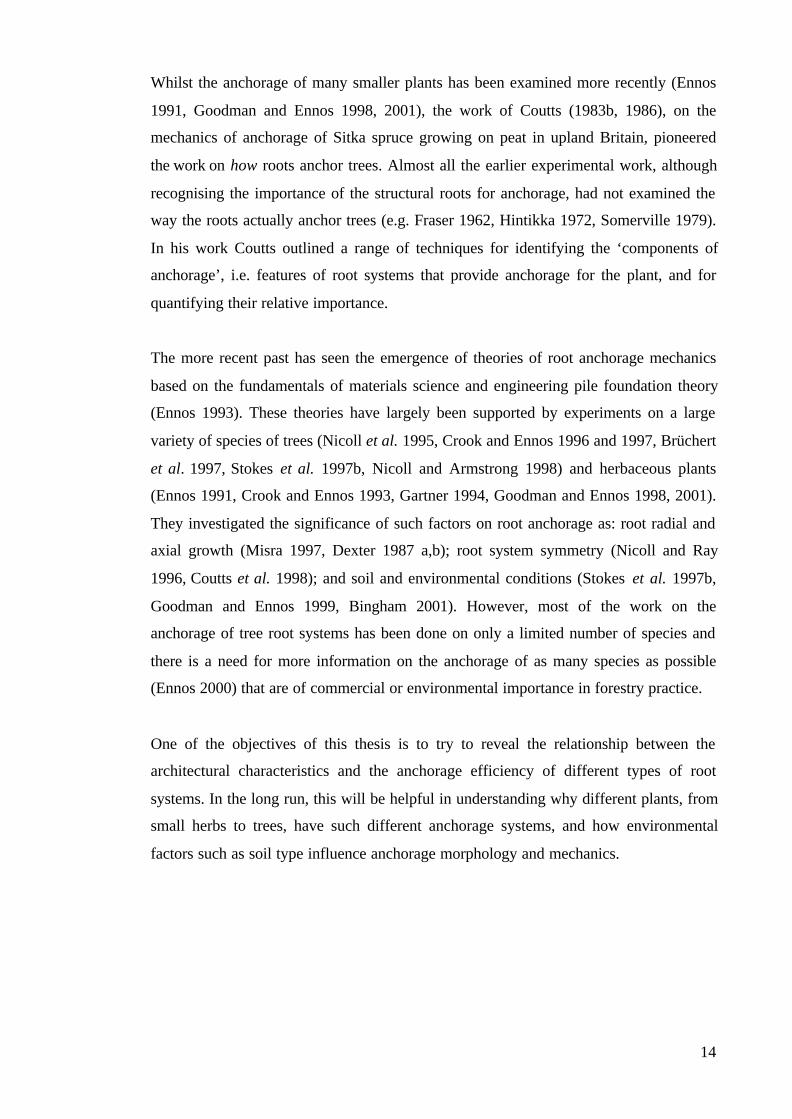
Whilst the anchorage of many smaller plants has been examined more recently (Ennos
1991, Goodman and Ennos 1998, 2001), the work of Coutts (1983b, 1986), on the
mechanics of anchorage of Sitka spruce growing on peat in upland Britain, pioneered
the work on how roots anchor trees. Almost all the earlier experimental work, although
recognising the importance of the structural roots for anchorage, had not examined the
way the roots actually anchor trees (e.g. Fraser 1962, Hintikka 1972, Somerville 1979).
In his work Coutts outlined a range of techniques for identifying the ‘components of
anchorage’, i.e. features of root systems that provide anchorage for the plant, and for
quantifying their relative importance.
The more recent past has seen the emergence of theories of root anchorage mechanics
based on the fundamentals of materials science and engineering pile foundation theory
(Ennos 1993). These theories have largely been supported by experiments on a large
variety of species of trees (Nicoll et al. 1995, Crook and Ennos 1996 and 1997, Brüchert
et al. 1997, Stokes et al. 1997b, Nicoll and Armstrong 1998) and herbaceous plants
(Ennos 1991, Crook and Ennos 1993, Gartner 1994, Goodman and Ennos 1998, 2001).
They investigated the significance of such factors on root anchorage as: root radial and
axial growth (Misra 1997, Dexter 1987 a,b); root system symmetry (Nicoll and Ray
1996, Coutts et al. 1998); and soil and environmental conditions (Stokes et al. 1997b,
Goodman and Ennos 1999, Bingham 2001). However, most of the work on the
anchorage of tree root systems has been done on only a limited number of species and
there is a need for more information on the anchorage of as many species as possible
(Ennos 2000) that are of commercial or environmental importance in forestry practice.
One of the objectives of this thesis is to try to reveal the relationship between the
architectural characteristics and the anchorage efficiency of different types of root
systems. In the long run, this will be helpful in understanding why different plants, from
small herbs to trees, have such different anchorage systems, and how environmental
factors such as soil type influence anchorage morphology and mechanics.

15
1.2 LINES OF INVESTIGATION
1.2.1 Modelling the Uprooting Resistance of Bulbs
The anchorage mechanics of bulbs has never been studied before despite the attempts
made to explore the resistance of cylindrical roots to uprooting (Ennos 1989, 1990,
Stokes et al. 1996, etc.). Acknowledging that uprooting is one of the most disastrous
situations a plant might encounter during its life (either from a grazing animal or during
gardening practice), it is important to find out the influence of different factors such as
bulb geometry and embedment depth, as well as the type of soil in which it is
embedded, on the uprooting resistance. In order to do this, in Chapter Two models of
bulbs with different sizes and shapes were embedded at different depths in two different
soil media. The mechanism of failure is described for each soil medium and an attempt
is made to relate the uprooting resistance of the models to their geometry and the soil
environment. The results are compared with the behaviour of real bulb plants grown in a
glasshouse.
1.2.2 Overturning Resistance of Rigid Tap Roots
The vast majority of self-supporting plants are likely to be pushed sideways by a
herbivore, or even more likely by the wind and either topple or lean permanently – a
phenomenon known as ‘lodging’. To neutralise lateral loads these plants are expected to
have at least one rigid element (Ennos 1993) that will resist with its bending resistance,
while the surrounding soil resists with its compressive resistance. Engineers have
formulated the theory of laterally loaded piles (Broms 1964 a,b) that might be used to
explain the behaviour of tap root dominated systems. Chapter Three combines the
engineering theory with practical biology by modelling different sizes of simple rigid
tap roots, embedding them at different depths in different soil media, pulling them over,
and recording the overturning moment. An attempt is made to relate the overturning
resistance of model tap roots to their size, embedment depth and the soil medium in
which they are embedded.

16
1.2.3 The Influence of Soil Compaction and Temperature on the Growth and
Development of Root Systems in Two Pinus Species
Two of the major soil physical properties that influence root growth are its mechanical
strength and temperature. Soil compaction, which results in mechanical impedance that
might restrict root growth, arises from mainly externally applied forces such as
trampling by animals or farm and tillage equipment, and as such it has been extensively
reviewed in the past (Barley and Graecen 1967, Taylor et al. 1972, Russel 1977,
Graecen 1986, Bengough and Mullins 1990, Glinski and Lipiec 1990, Bennie 1996). On
the other hand, of all stresses associated with root initiation and development,
temperature stress is most common; soil temperature changes can have significant
effects on the growth and development of the root systems as discussed by Brouwer and
Hoagland (1964), Cooper (1973), Nielsen (1974), Glinski and Lipiec (1990), Bowen
(1991), and McMichael and Burke (1996). However, most of the studies investigating
the effect of soil mechanical impedance, as well as the vast majority of the
investigations of the effects of the temperature on root system growth and development
have concentrated on crops or other fast growing plants. The influence of these factors
on the axial elongation and lateral root initiation and development in the root systems of
young Pinus sylvestris and Pinus peuce seedlings is investigated in Chapter Four of this
thesis. The results of this study deepen the knowledge on two of the most important
factors influencing root initiation and development in the early stages of growth, and
add to the number of tree species investigated.
1.2.4 The Effect of Unidirectional Stem Flexing on Shoot and Root Morphology
and Architecture in Young Pinus sylvestris Trees
Lateral loading of the plant stem can result either in root system failure (windthrow) or
stem failure. Mechanical stresses experienced this way may cause alterations in both
shoot and root growth, a process called thigmomorphogenesis (Jaffe 1973). Many of the
previous studies on this subject have concentrated on shoot responses to lateral loads
(Neel and Harris 1971; Jaffe 1973; Rees and Grace 1980, Telewski 1995), while root
system responses to stresses caused by external loading have been investigated only in
more recent years (Gartner 1994, Goodman and Ennos 1996, 1997, 1998, 2001; Stokes
et al. 1995, 1997b, Watson 2000), and even then only rarely in pine trees (Rees and
Grace 1980; Fredericksen et al. 1993, Downes et al. 1994, Valinger et al. 1994,;
Telewski 1995, Lindstrom and Rune 1999, Moore 2000, Watson and Tombleson 2002).

17
Chapter Five presents the effect of unidirectional stem flexure of young Scots pines on
their root system morphology and architecture, showing the extent to which the
response to mechanical stimulation is localised in the root system, as well as the effect
of the mechanical perturbation on the overall morphology of the tree. The changes in
root system morphology and architecture as a consequence of the mechanical
stimulation, are also compared with the similar changes in other, previously investigated
species.
1.2.5 A Morphological and Mechanical Study of the Root Systems of Suppressed
Crown Scots Pine Pinus sylvestris
Previous studies (Somerville 1979, Coutts 1983a, Nicoll et al. 1995, Coutts et al. 1998)
have shown that root system asymmetry can greatly affect the stability of trees. Some
aspects of root system symmetry, such as the origin and growth of primary roots (Coutts
et al. 1999) and their distribution around the tree trunk (Somerville 1979, Coutts 1983a)
have been investigated in the past. However, no investigation has been carried out on
the possible connection between root system asymmetry, perhaps caused by
environmental factors, and the stability of the tree. In Chapter Six a mechanical
investigation of the stability and anchorage symmetry of suppressed crown Scots pine
Pinus sylvestris trees growing in clay soil were combined with a morphological
investigation of the lateral root system. The well-established winching method of Coutts
(1983b, 1986) was used to investigate the resistance of the trees to lateral loads, which
was then related to the distribution of the major lateral root cross-sectional area around
the tree and with depth, as well as to the size of the tree trunk. An attempt was made to
correlate the asymmetry in anchorage with the asymmetry in the root system as well as
to define the major components of anchorage.
1.2.6 Anchorage Mechanics and Asymmetry in the Root System of Macedonian
Pine Pinus peuce (Gris.)
Acknowledging that the overall stability of a tree might be significantly reduced by
asymmetry in the root system (Coutts et al. 1999), Ennos (2000) suggested that a more
advanced knowledge of the root morphology and architecture of more tree species
might provide further insight into the way in which the form is related to the function in
root systems. Using the methods for exploring the distribution and function of roots in
the soil in connection to a tree’s anchorage used and described in Chapter Six of this
18
thesis, an investigation of the asymmetry of the overall root system in Macedonian pine
Pinus peuce was carried out. The vertical distribution of root biomass, especially in
relation to soil properties and competition for nutrients was also investigated. The
results of this investigation are presented in Chapter Seven and these findings are
compared to the ones for other previously investigated species, particularly to the
related P. sylvestris which had grown in contrasting environmental conditions. This will
help in gaining more knowledge on the factors that determine root development and
root biomass distribution.

19
CHAPTER TWO: MODELLING THE UPROOTING RESISTANCE
OF BULBS: THE EFFECT OF SHAPE, SIZE, DEPTH, AND SOIL
TYPE
2.1 INTRODUCTION
The term ‘bulb’ is usually used to refer to the underground, fleshy storage structures of
some herbaceous plants. However, only some of the plants commonly called ‘bulbs’
actually are bulbs. The simple definition of a bulb is ‘any plant organ consisting of a
short stem bearing a number of swollen fleshy leaf bases or scale leaves, with or without
a tunic, the whole enclosing the next year’s bud’ (Rees 1972). Onions, for example,
have the features of a typical bulb together with their characteristic shape (Figure 2.1),
having the largest diameter near the bottom and tapering to a point at the top, while
nutrient uptake and/or contractile roots originate at a basal plate.
Figure 2.1 The features of a typical bulb. Developing leaves and flower buds areprotected by layers of leaf scales. Roots emerge from the basal plate.
Bulbs or bulb-like plants are usually perennials, having a period of growth and
flowering, followed by a period of dormancy at the end of each growing season. During

20
the dormancy period they die back to ground level, losing their roots. The primary
function of a bulb is to store energy and nutrient reserves to ensure the plant's survival.
This bulbous habit therefore confers a measure of success to the plant, especially as a
means of enduring extreme arid or cold seasons, or seasonal shade under a deciduous
woodland canopy.
The main function of the contractile roots is to maintain the deep position of the bulb
(Rees 1972, Pütz 1991, 1992a,b; 1996) where it is safe from potential herbivores and
may also provide more effective anchorage for the plant, especially against uprooting.
Of the few tests and observations which have been conducted on contractile roots, most
have investigated how they cause downward movements of bulbs in the soil (Pütz
1991,1992a,b; 1993, 1996). The resistance of bulbs to downward movement has also
been investigated by Pütz (1992b, 1996). However, the resistance of bulbs to upward
movement (as a result of grazing or gardening activities, for example) has not been
investigated, although it might occur as a result of grazing or of the traditional method
of harvesting which involves pulling the bulbs out of the soil or undercutting them
before their extraction (Rees 1972).
Our ignorance about bulbs is in sharp contrast to our knowledge about the resistance of
cylindrical roots (Ennos 1989, 1990, Stokes et al. 1996, etc.) and root systems (Ennos
1991) to uprooting. This is even though, at least for some part of the year, bulbs lack
roots and so must anchor themselves in the soil. Studies on roots have shown that root
form and architecture are the dominant influence on the uprooting resistance of plants
(Ennos 1993, Stokes et al. 1996, etc.); however, no proper investigation has been
carried out on how the shape and size of bulbs influences their resistance to upward
movement.
Fortunately, though botanists have failed to test the anchorage of bulbs, engineers have
performed fairly similar tests on plate-like concrete or steel models (Balla 1961, Boone
1975) and have described the basic mechanics of the process. However, they have not
specifically investigated the influence of model shape on the mechanical behaviour or
the influence of model size on the overall resistance to upward movement through soil.
Therefore, it can be seen that the influence of the shapes and sizes of bulbs on the
uprooting resistance has not been investigated, but intuitively they might be suspected

21
to have a big effect. In addition to this, increasing the depth of embedment might be
expected to increase the resistance of the model to upward movement, both in
cohesionless sand and in cohesive agricultural soil, in which completely different
behaviour might be expected.
In this study, therefore, a series of tests were carried out to investigate the effect of
shape, size, depth, and soil type on the uprooting resistance of model bulbs, to
determine whether bulbs are optimally designed to prevent uprooting. In order to
determine the extent to which these factors influence the uprooting resistance in real
bulbs, a series of uprooting tests were also carried out on garlic and onion plants, with
and without their roots.
2.2 MATERIALS AND METHODS
2.2.1 Models
The bulb models used in this experiment were made in several different shapes and
sizes by packing different amounts of plasticine (Lewis’s non-toxic ‘Newplast’) on to a
spruce ‘stem’ of cylindrical shape (4.5 mm in diameter, 30 cm long). They were later
embedded in different soil media.
2.2.2 Soils
Two soil types were used in this investigation. The first soil was a dry, cohesionless,
Mersey river sand. For the tests in this soil, the models were placed in steel cylindrical
container of diameter 25.4 cm, and height 25.4 cm, on a thick layer of sand (cca. 10 cm)
and more sand was poured over the models to the desired level, a process which ensured
that it was loose and uncompacted. John Innes no.3 compost (Keith Singleton’s,
Egremont, Cumbria) was selected as a second soil type, to represent a typical, albeit
weak, agricultural soil. The models were placed in plastic tubes with a diameter of 12.5
cm, large enough to ensure that the sides did not interfere with the soil failure surface
even for the largest models at the largest embedment depth. A layer of soil (cca. 4 cm)
was first laid in the tubes, then the models were placed in the centre of the tube while
loose soil was poured over the model to the desired level. The soil was then given

22
cohesion by saturating it with water, and draining it for one day in laboratory conditions
(t=20ºC, 50% humidity), to gain a field capacity close to that of a natural agricultural
soil.
2.2.3 Mechanical Tests
Models’ stems were clamped to and were pulled out of soils using an INSTRON 4301
universal testing machine (Figure 2.2), with a 0.1 kN load cell, at a speed of 80 mm per
minute. During the testing, a graph of force against absolute displacement was plotted
by an interfacing computer, and used to measure the maximum pullout force. The
pattern of surface failure was also observed.
Figure 2.2 The apparatus and method for uprooting model bulbs. The model isembedded in a soil medium encased in a plastic tube, and clamped to the testingmachine. The crosshead moves upwards with a constant speed and pulls the model outof the soil.
2.2.4 The Investigations
To investigate the phenomenon, a range of tests were carried out.
Preliminary tests: To investigate the effect of shape on uprooting resistance, six
different shaped models (cone, cylinder, bulb, sphere, inverted cone and inverted bulb)
were made. Each of the models contained the same amount of material (25 g of
movingcrosshead
INSTRONtesting machine
model
perforated bottom
soil

23
plasticine) and had the same maximum diameter of 3.3 cm, so that their heights ranged
from 3.3 to 3.9 cm. Each was embedded in sand with their lowest surface at three
different depths: 5 cm, 7 cm and 10 cm, and pulled out. Tests were repeated ten times
for each model at each depth. The failure at the soil surface was observed during the
uprooting process, noting down the diameter of disturbed soil. The maximum resistance
was measured and plotted against the absolute displacement.
Main tests: The three shapes that showed the highest resistance to uprooting in the
preliminary tests were chosen for more detailed study, which involved additionally an
investigation of the effects of size, depth and soil type on the uprooting resistance of the
bulbs. These three shapes were modelled in three varieties each: with 12.5 g plasticine,
producing models with diameter 2.4 cm; with 25 g plasticine for models with 3.3 cm
diameter; and with 50 g plasticine for 4.2 cm diameter. Each size and shape of model
was then tested by pulling it ten times out from three different depths: 5 cm, 7 cm and
10 cm both of sand and of agricultural soil. During the tests, the diameter of disturbed
soil on the soil surface was noted. These observations justified the usage of the 12.5 cm
diameter tubes.
The results were analysed using analysis of variance (ANOVA) to determine the
importance of different factors in resistance of the models to uprooting.
Material tests on soils: To obtain the shear strength of both soil media, standard
engineering soil tests were carried out.
The material properties of Mersey river sand – the dry weight γ=26.5 kNm-3, the
cohesion c=0.0 kNm-2, and the angle of internal friction ϕ=30º – were obtained from
Boone (1975).
The shear strength of the agricultural soil was determined with a standard shear box test.
A soil specimen was prepared in the same way as it was for the testing of models: fully
saturated and then allowed to drain for a period of one day. This sample was laid in a
shear box of dimensions 6 cm x 6 cm x 4 cm which was made of two parts. The upper
part was pushed over the lower and the maximum force required to shear the specimen
was measured and recorded with a Mecmesin portable force indicator PFI-200N.

24
To obtain the cohesion and the angle of internal friction of this soil type, this standard
small shear box test (BS1377:Part7:1990:4, and ASTM D3080) was performed on a
drained sample, a method introduced by Ennos (1989). A graph of shear stress vs.
normal stress was plotted. The slope of the graph gave the angle of internal friction,
while the intercept represented the cohesion of the sample. This method showed that
this type of soil has dry weight of γ=16.5 kNm-3, cohesion c=0.38 kNm-2, and angle of
internal friction ϕ=21º.
2.2.5 Anchorage Tests on Real Bulbs
Planting and growing of the bulbs. To investigate the influence of the size, shape and
embedment depth on the uprooting resistance in real bulbs, one garlic variety (Allium
sativum, Suttons seeds, UK), and one variety of pickling onion (Allium cepa, (Paris
Silverskin) Suttons seeds, UK) were planted and grown at the University of Manchester
Experimental Grounds.
Garlic bulbs were grown from cloves planted in February 2002, in plastic pots (10 cm in
diameter, 12.5 cm height) in John Innes no.3 compost (Egremont, Cumbria) and
covered with black plastic foil until they germinated. A layer of soil was first laid in the
pot, the clove was placed in the middle of the pot, and then covered with another layer
of soil using light compaction.
Onion bulbs were grown from seeds, first being left in moist verniculite for ten days and
then potted in small plastic pots (10 cm in diameter, 12.5 cm height) in John Innes no.3
compost (Egremont, Cumbria) in February, 2002. The planting was carried out in the
same way as for the garlic.
Both onion and garlic were grown for 6 months in a glasshouse cubicle, in a controlled
temperature environment of 15ºC to 23ºC, and were watered regularly. The pots were
arranged in matrices 10 rows x 10 columns for both species, ensuring that all of the
plants receive the same amount of light during the day.
Uprooting tests and measurements. The uprooting tests on both onion and garlic
plants started six weeks after their planting, when the root system was already formed
and the formation of the bulb had already started. Before the test each plant was marked
at the soil surface level with a permanent marker. In order to investigate the maximum

25
uprooting force required to uproot the bulb together with the intact roots, the plants
were uprooted with an apparatus consisting of a cork padded clipper which gripped the
plant stalk at one end, and at the other end connected to a portable force meter
(MECMESIN PFI-200N) (Plate 2.1). The apparatus together with the clipped plant stalk
was manually moved upwards at a rate of cca. 0.5 cm per second until the whole bulb
together with the root system was out of the soil. The maximum uprooting force
required to uproot the bulb out was measured and displayed on the portable force meter.
26
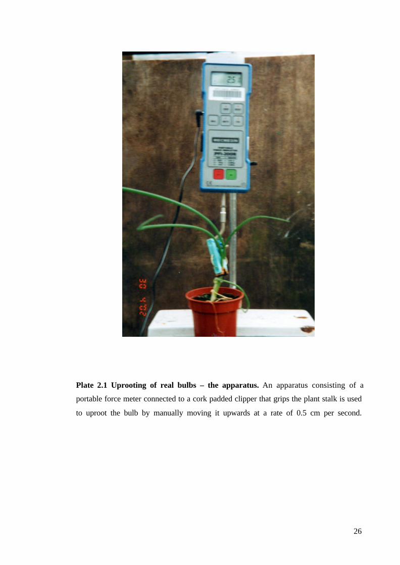
Plate 2.1 Uprooting of real bulbs – the apparatus. An apparatus consisting of a
portable force meter connected to a cork padded clipper that grips the plant stalk is used
to uproot the bulb by manually moving it upwards at a rate of 0.5 cm per second.

27
The remains of the soil were then washed away from the bulbs, and the maximum
diameter of the bulb measured with callipers. The embedment depth was measured with
a ruler from the root plate to the point on the stem which marked the soil surface level.
To investigate how much of the uprooting resistance was contributed by the bulb alone,
the root system was then carefully cut off at the basal plate with scissors, and the plant
was replanted at the same embedment depth into the same pot, with the soil prepared in
the same way as it was when originally planted. The soil was watered to saturation, and
left to drain for 24 hours to achieve water content close to the field potential. The plants
were then uprooted again with the same apparatus, at a same rate of manual vertical
movement.
To investigate the importance of the bulb for uprooting resistance, the percentage
contribution of the bulb to the overall uprooting resistance of the plant was calculated
by dividing the maximum uprooting force of the bulb without roots by the maximum
uprooting force of the intact plant.
To monitor the changes in the uprooting resistance of the bulbs throughout the growing
season the uprooting tests were carried out 6, 8, 9, 11, 12, 13, 14, 16, 19, and 24 weeks
after planting.
2.3 RESULTS
2.3.1 Preliminary Tests
During the preliminary testing, on initial upward movement of the model a sand surface
of diameter 0.75 times the model diameters was disturbed around the stem. Fairly small
soil bodies were noticed on the upper side of the models as they emerged from the sand.
The force rose to a maximum at displacements of approximately 3 to 3.5% of the depth.
The maximum uprooting resistance of the different models is shown on Figure 2.3 The
mean force varied from 0.293 N for the inverted bulb shape at 5 cm, to 4.19 N for the
cone at 10 cm depth.

28
Figure 2.3 The uprooting resistance of six different shapes of bulb models. Resultsare for cone, cylinder, sphere, bulb, inverted cone and inverted cylinder shapes withmaximum diameter d=3.3cm, embedded at three different depths (5 cm, 7 cm and, 10cm) in sand. Error bars indicate ± SE.
Two-way ANOVA of the results showed that both model shape and depth had a
significant effect (p<0.001) on the uprooting resistance. The cone was most resistant to
uprooting followed by the bulb, the cylinder, the sphere, the inverted cone and the
inverted bulb. On average, the best shape was the cone, which resisted on average a
20.5% greater force than the bulb, 23.5% better than the cylinder, 106.4% better than
the inverted cone, 112.3% better than the sphere, and 136.4% better than inverted bulb.
The three shapes that performed best: the cone, the bulb and the cylinder, were therefore
chosen for further studies. Resistance also rose with depth (p<0.001), models at 5 cm on
average having an uprooting resistance 61.2% of those at 10 cm.
There was a significant (p<0.001) interaction between the two factors: model shape and
depth. The resistance of the different models increased by different amounts when the
embedment depth increased. Inverted cone models showed the greatest increase in
uprooting resistance with depth, and cylindrical ones the least.
2.3.2 Main Tests
Models in sand: The behaviour during the uprooting tests on the cone, bulb and
cylinder was similar to that seen in the preliminary tests; the sand failed in shear near
0
0.5
1
1.5
2
2.5
3
3.5
4
4.5
5
5cm 7cm 10cmDepth
For
ce [N
]
Cone
Cyllinder
Sphere
Bulb
Inv.Bulb
Inv.Cone
29
the upper surface of the model, allowing only a small soil body to form above the
model. The failure of the sand was local and disturbed an area of diameter
approximately 0.75 times the largest model diameter around the stem, on the surface of
the soil medium before emerging on the surface. The maximum uprooting forces
measured in these models ranged from 0.713 N for a bulb of 2.4 cm diameter at 5 cm
depth to 4.242 N for a bulb of 4.2 cm diameter at 10 cm depth. Results are shown for
the bulb shaped models in Figure 2.4.
Three-way ANOVA showed that shape, size and depth all significantly (F1,269=30.602,
p<0.001) affected the uprooting resistance of bulbs in sand. Just as in the preliminary
tests, it was found that cone shaped models were the best, performing on average 20.5%
better than bulbs, and 23.5% better than cylinders.
The size of the model was also a significant factor (F1,269=29.467, p<0.001) in resisting
uprooting, but the effect was not great. The resistance of the models actually decreased
with their size before going up again. Bulb shaped models are an example of this trend
(Figure 2.4). The resisting force decreased on average by 10.5% when increasing the
maximum diameter from 2.4 cm to 3.3 cm, but went up on average by 33.3% in the 4.2
cm diameter models. Overall, regression of LogF vs. LogD for each shape at each depth
showed that resisting force is less than proportional to the largest diameter of the bulb.
The slope varied from 0.212 to 0.658 and in five out of nine cases the slope was
significantly (p<0.05) less than one.
30
Figure 2.4 Uprooting resistance of bulb shaped models with three differentdiameters (2.4 cm, 3.3 cm and, 4.2 cm) at three different depths (5 cm, 7 cm and, 10cm) in sand. The uprooting resistance of the model bulbs increased with the depth andwith the increase in model diameter (except for the models with d=3.3 cm at 10 cmdepth). Error bars indicate ± SE.
The resistance increased significantly (F1,269=628.198, p<0.001) faster with the
embedment depth Df (Figure 2.4). In particular the smallest bulbs proved to be far more
efficient at larger embedment depths, resisting more than four times higher forces at 10
cm than at 5 cm depth. LogF vs. LogDf regression for each shape and each size of
model, however, showed that the slope of these curves ranged from 1.209 to 2.444, in
four out of nine models the slope was significantly (p<0.05)greater than one, and in six
out of nine models the slope was significantly (p<0.05) less than 2.
There were also significant interactions between the factors (p<0.001). The uprooting
force increased significantly (F1,269=22.465, p<0.001) more with diameter for the
cylinders than the other shapes. The uprooting force also increased significantly
(F1,269=8.177, p<0.001) more with embedment depth for the bulb-shaped models than
for the cylindrical ones, so the slope of the LogF vs. LogDf curve for bulb-shaped
models is steeper than for the cylinders
Models in agricultural soil: A different pattern of soil failure was observed in
agricultural soil from that seen in sand. Soil failed in shear around the model, but
cohesion allowed the formation of a large soil body above the model. The failure
surface of this soil body was curved and disturbed the soil on the surface to a diameter
that was 2 to 2.5 times the largest diameter of the model, complying with the theory of
0
1
2
3
4
5
6
2 . 4 3 . 3 4 . 2
D i a m e t e r [ c m ]
Fo
rce
[N
]
a t 5 c m
a t 7 c m
a t 1 0 c m

31
resistance of shallow foundations under tension, best described in Balla (1961). This
fact justified the use of the 12.5 cm diameter plastic tubes, which ensured that there was
no interference between soil failure body and the walls of the tube. The smaller
diameter models showed a maximum force at higher absolute extensions (3 to 5 mm,
compared to 2 to 3 mm for the larger diameters) at every depth, particularly at 10 cm
depth. This is probably because there were different types of breakage mechanisms:
larger models broke the soil in a curved surface, while the smaller ones broke it locally
in the vicinity of the model itself. A negative water pressure was observed after the
pullout of the models in agricultural soil, since a certain amount of water drained
through the perforated bottom of the tube.
The resisting forces measured for the models in agricultural soil ranged from 2.765 N
for the 2.4 cm diameter cylinder at 5 cm depth, to 13.664 N for the 4.2 cm diameter
cone at 10 cm depth, which is approximately three times higher than the resistance in
the sand. Three-way ANOVA also showed significant (p<0.001) effects of all three
factors (shape with F1,269=91,756, size with F1,269=170.004, and depth with
F1,269=337.285) just as in the sand.
There were similar differences between the shapes as in the sand. Conical models
performed on average 20% better than bulbs, and 29% better than cylinders at all
depths. Typical example of that difference is shown for the cylindrical and the bulb-
shaped models of 2.4 cm diameter on Figure 2.5.

32
Figure 2.5 A comparison between uprooting resistance of the cylinder and bulbshaped models. The results are for models with maximum diameter d=2.4 cm,embedded at three different depths (5 cm, 7 cm and, 10 cm) in agricultural soil. Theuprooting resistance of the models increased both with depth and with the increase inmodel diameter, but the bulb shaped model always resisted better than the cylindershaped one. Error bars indicate ± SE.
Measurements on the models with same shape but with different diameters also showed
a greater effect of diameter. The resistance increased by 27.8% on average, when
increasing the diameter from 2.4 cm to 3.3 cm, and by an additional 34.3% when
increasing the diameter from 3.3 cm to 4.2 cm. Slopes of the regression line of LogF vs.
LogD were not significantly (p>0.05) different from 1 for the three shapes at all three
depths in agricultural soil, the slopes of these curves ranging from 0.761 for cone
shaped models, to 1.054 for bulb shaped ones. This suggests that the maximum
resistance is directly proportional to the diameter of the model.
Increasing the embedment depth increased the uprooting force significantly
(F1,269=337.285, p<0.001), but less than in sand. The bulb-shaped models showed a
typical increase of the uprooting resistance with the depth, and these results are shown
on Figure 2.6. The slopes of regression lines of LogF vs. LogDf showed slopes ranging
from 0.969 (bulb shape) to 1.070 (cylinder) for the models in agricultural soil. None of
the slopes of the nine different models were significantly different from 1, showing that
uprooting resistance is directly proportional to the embedment depth.
0
2
4
6
8
1 0
1 2
1 4
1 6
5cm 7cm 10cm
Depth
Fo
rce
[N
]
Cylinder
Bulb

33
Figure 2.6 Uprooting resistance of bulb shaped models with three differentdiameters (2.4 cm, 3.3 cm and, 4.2 cm) at three different depths (5 cm, 7 cm and, 10cm) in agricultural soil. The uprooting resistance increased approximatelyproportionally with the embedment depth. Error bars indicate ± SE.
Again, there were significant (p<0.001) interactions between the factors. As in sand,
the uprooting force increased significantly (F1,269=3.124, p=0.016) with the diameter for
the cylindrical models than for the other shapes, but unlike then, this time even more
with the depth (F1,269=5.881, p<0.001).
2.3.3 Anchorage Tests on Real Bulbs
Uprooting tests on real bulb plants worked well and produced results comparable to the
ones from the model experiments. The resisting force of both the intact plants and bulbs
to uprooting in both species rose to its maximum during uprooting at absolute
extensions ranging form 3 to 10 mm before falling down again, in a similar fashion as in
the model investigations.
The shape of the bulbs changed throughout the experiment. Plate 2.2 (a, b) shows that
the underground part of the garlic seedlings was cylindrical in shape, resembling our
cylindrical models for the first 9 weeks after planting, but they then started to lay down
more material near the root plate, so they resembled our conical shaped models. The
average maximum bulb diameter increased from 1.58±0.11 cm six weeks after planting,
to 2.35±0.23 cm 24 weeks after planting.
0
2
4
6
8
1 0
1 2
1 4
2.4 3.3 4.2
Diameter [cm ]
For
ce [
N ]
a t 5 c m
a t 7 c m
a t 1 0 c m

34
Onion bulbs also kept an approximately cylindrical shape until 11 weeks after planting
when the material started to be laid down more near the root plate and they started to
resemble our bulb shaped models (Plate 2.2 c, d). The average maximum bulb diameter
increased from 0.63±0.08 cm six weeks after the planting, to 4.84±1.43 cm 24 weeks
after the planting.

35
a) b)
c) d)
Plate 2.2 Development of bulb form in garlic (a, b) and onion (c, d). a) Six-week-oldgarlic with cylindrical shape of its underground part; b) 19-week-old garlic with alreadyformed bulb with conical shape; c) 8-week-old onion with cylindrical shape of itsunderground part; d) 19-week-old onion with bulbous shape of its underground part.

36
Figure 2.7a shows that the average maximum uprooting resistance of the intact garlic
plants, increased from the start of the experiment and reached its maximum 16 weeks
after the planting before decreasing again until the end of the experiment. The uprooting
resistance of the bulb without roots also followed this trend, reaching its maximum 13
weeks after planting, before dropping towards the end of the experiment.
a)
b)
Figure 2.7 Average maximum uprooting resistance in a) garlic and b) onion. Theexperiments started six weeks after the planting when the bulbs started to form and itlasted until 24 weeks after the planting. Every point in the graph represents a meanvalue of ten samples. Solid symbols for intact plants, empty symbols for plants withoutroots. Error bars indicate ± SD.
The average maximum uprooting resistance of the intact onion plants (Figure 2.7b)
showed similar pattern; after the initial increase, it reached its maximum 13 weeks after
the planting, before falling again until the end of the experiment. In sharp contrast with
the garlic, the uprooting resistance of the bulb without roots did not follow this trend,
0
5
10
15
20
25
5 10 15 20 25Weeks after planting
Upr
ootin
g re
ista
nce
[N]
0
5
10
15
20
25
5 7 9 11 13 15 17 19 21 23 25Weeks after planting
Upr
ootin
g re
ista
nce
[N]
37
showing a constant increase throughout the duration of the experiment, though it did
level off towards the end.
Throughout the experiment the average embedment depth of garlic did not change
significantly: from 5.43±0.09 cm six weeks after planting to 4.74±0.07 cm 24 weeks
after planting. However, the embedment depth of the onion increased from 1.35±0.08
cm six weeks after the planting to 2.90±0.09 cm 24 weeks after planting.
The relative contribution of the bulb to the overall uprooting resistance in garlic showed
no pattern over time ranging between 29.02±2.99 % seven weeks after planting, to
53.52±4.32 %, nine weeks after planting. In contrast, the relative contribution of the
bulb in onion plants increased throughout the experiment, from 15.55±1.89 % six weeks
after planting to 37.59±3.02 % at the end of the experiment.
2.4 DISCUSSION
The testing procedure described above worked well, and has shown the relative
importance of factors like shape, depth of embedment, and size in the uprooting
resistance of the bulbs; cones resist uprooting most strongly, followed by bulb shapes,
while depth has a stronger influence in sands than in agricultural soils, and diameter a
stronger influence in agricultural soils. These results can be explained in engineering
terms, as they are typical of the behaviour of shallow foundations.
In cohesionless soils the soil failure mechanism due to uprooting forces suggests that
the shear resistance of the soil is the most important factor in the absence of cohesion.
When an uprooting force is applied, the soil above the model slides along the shearing
surfaces (Figure 2.8 a) and small soil failure bodies are formed. Most of the force is
required to cause local shear failure. The weight of these failure bodies only slightly
increases the uprooting resistance of the model in this soil medium.

38
a) b)
Figure 2.8 Patterns of soil failure in a) sand and b) agricultural soil. When theuprooting force F acts on the model, the soil above the model (ABCD and A1B1C1D1)forms a, so called, ‘soil failure body’. This soil fails in shear along the outside surfacesallowing the model to move upwards. Wi - the weight of a certain soil segment, D - themodel diameter, h – the model height, H+h - the embedment depth.
In cohesive agricultural soils and clays, on the other hand, the uprooting force causes
shearing of the soil above the model along a curved shearing surface (Figure 2.8 b). The
soil cohesion allows the formation of a soil failure body confined within this surface –
an amount of soil far larger than the one in sand. According to Balla (1961), the ultimate
pullout resistance of a model in cohesive soil is the sum of the self weight of the soil,
plus the side sliding resistance of the failure surface (Figure 2.8 b); these both depend
on the geometry of the model and the physical/mechanical properties of the soil. The
shearing resistance of the soil contributes only slightly towards the uprooting resistance
of the model.
The implications of these results and the theory behind them on the design of bulbs are
evident. First and foremost, these results suggest that to maximise anchorage bulbs
should be conical. The depth and size of the bulb also both have a significant effect but
to different extents in the two different media. Increasing depth has a greater effect in
sand, while increasing diameter has a greater effect in the agricultural soil.
Conical bulbs, however, are not common in nature. This may be because sharp edges
are not favoured by nature because of possible high-stress concentrations in them,
which could lead to breakage even under small loads. Bulb shapes which closely
resemble a cone, do show stronger resistance to uprooting than the spheres.
H
h
D
A
B C
D
C1
D1
H
h
D
A
B
C
E Factual failure surface
sliding surfaces
A1 B1

39
Furthermore, an optimal bulb shape should also enable relatively easy downward
movement by the use of contractile roots, because the downward movement of bulbs
(Pütz 1992a,b; 1993, 1996) strongly affects the enhancement of the bulb anchorage and
its uprooting resistance.
In order to have larger soil failure bodies in cohesionless soils, it is necessary to have
the model embedded at a larger depth to ensure greater soil shear strength, and to a
lesser extent to have larger model diameters in order to mobilise as large a shear surface
as possible. This combination suggests that the conical shaped bulbs would be the best
to resist uprooting in cohesionless soils because the basal part of the bulb would be the
widest and would have the largest surface area. It is also conceivable that a wider angle
at the top of the bulb would allow more efficient formation of a small soil failure body
that, with its weight, will also contribute towards greater uprooting resistance, together
with the shear resistance of the sand. However, because the size of the model has less
effect it might therefore be expected that the bulbs in cohesionless soil should split into
lots of smaller bulbs with a larger total surface area that would resist uprooting better.
A bulb designed by these criteria partially coincides with the form of the real bulbs in
this study, as well with the recorded forms of bulbs embedded at different depths (Pütz
1996). For example, rounder bulbs tend to be found immediately beneath the soil
surface and more elongated ones at greater depths. Smaller and broader bulbs with a
large surface area would be favoured in sandy soil, because that should be expected to
enhance the shear resistance of the sand that fails only locally around the bulb.
Furthermore, bulbs in sandy soil might be expected to be found at larger depths because
the shear resistance of the sand increases with the depth where it is expected to be more
compact.
Considering bulbs in agricultural soil, it is clear that the cohesion of this type of soil acts
to greatly increase uprooting resistance. The maximum diameters of the bulbs should be
located at deeper levels to enable formation of as large a soil failure body as possible
that will, with its weight and greater surface area and hence friction, contribute largely
to the resistance of upward forces. In this respect, the poor performance of the
cylindrical models in clay was probably due to its shallower mobilised soil body; the
cylinder activates a smaller amount of soil in the friction cylinder above the largest
diameter of the model. The cone and the bulb activate almost the same amount of soil,
40
but the curvature of the bulb does not allow so efficient a formation of a friction
cylinder over the model (it acts as a soil-dynamic form, or enhances the ‘channel effect’
Pütz (1992a)).
In addition, the surface area of the bulb, on the other hand, is not as important as for the
bulbs in sandy soils, because the cohesion of the agricultural soils acts towards the
formation of larger soil failure bodies. Therefore, more rounded and spherical shapes of
bulbs might be expected in cohesive agricultural soils.
The influence of size is expected to be the crucial factor in the uprooting resistance of
bulbs in agricultural soils. Bulbs with largest diameters at maximum possible depths are
expected to be favoured in order to maximise the formation of efficient soil failure body
above the bulb that will add to the uprooting resistance with its weight.
Finally, it is clear that cohesive soils (in this case a model agricultural soil) are far better
than sandy soils in resisting uprooting. However, cohesive soils, especially those with
larger clay content, tend to become stiffer in dry periods, and may pose a larger
resistance to root penetration and downward movement of the bulb. In the light of this,
agricultural soils with water content close to the field potential are ideal medium for
embedding bulbs.
The uprooting tests on the garlic and onions showed that the uprooting behaviour of the
real bulbs was similar to those of the models and produced results comparable to the
ones of model experiments. The uprooting forces recorded for bulbs without roots were
of the same order of magnitude as the ones recorded for the model bulbs. For example,
the uprooting resistance of a 19-week-old garlic bulbs (Df=4.74±0.07 cm, D=2.35±0.83
cm), with an approximately conical shape (Plate 2.2b) was on average 5.35±2.95 N.
This is comparable to that recorded for the conical model bulbs (Df=5 cm, D=2.4 cm):
4.25±0.97 N. The garlic and onion bulbs also showed similar trends of anchorage
efficiency with embedment depth as the model bulbs; the deeper embedded garlic bulbs
resisted uprooting better than the shallowly embedded onion bulbs. One setback of this
study is the fact that the onion bulbs did not reach the depths investigated in the model
study, and so the results of the uprooting tests on real onion bulbs could not be fully
compared to the ones from the model study. It is important to note also that both garlic
and onion bulbs showed an increase of their uprooting resistance with an increase in
41
their respective diameters, just as predicted in the model study. This was more evident
for onion bulbs where the increase in diameter (and thus resistance to uprooting) was
more dramatic than in garlic.
The shape of the bulbs also affected the resistance to uprooting, as predicted in the
model study; the conical shape of garlic bulbs resisted uprooting on average 20% – 40%
better than the more rounded bulb shape of the onion.
The shapes of the investigated real bulbs supported the concept of an optimal bulb shape
that will improve a bulb’s resistance to uprooting. More rounded shapes with
comparatively larger diameters, like the ones in our onion, were embedded more
shallowly, with their shape enabling easier downward movement, easier increase in
embedment depth, and in turn, increase in uprooting resistance. On the other hand, the
conical shaped garlic bulbs, having relatively smaller maximum diameters than the
onion bulbs, were embedded deeper in the soil, increasing their uprooting resistance by
ensuring greater soil shear resistance and larger soil failure bodies above them during
the process of uprooting.
But just how important are bulbs for anchorage? Our results showed that they do have
an important contribution to anchorage, resisting from 15% up to 50% of the total
vertical uprooting force of the whole plant. This should indeed help prevent uprooting,
especially as the contribution of the bulb in the total uprooting resistance of the plant
increased as the plant aged. At the end of the season, as roots die off, the resistance of
the bulb may be crucial in preventing uprooting. The bulb’s position, close to the soil
surface, might also help shield the roots from disturbance, and ensure that the growth of
the plant is maintained.
The results of this experiment have therefore shown that bulbs and bulb shaped roots are
well suited for resisting uprooting. Although the resistance of the bulb would only be
crucial when the root system is not functioning (either dried off at the end of the season,
eaten by soil herbivores, or infected by a root decease), this study has shown that the
bulbs have an important role in anchorage of the plant.
42
CHAPTER THREE: OVERTURNING RESISTANCE OF RIGID
TAP ROOTS
3.1 INTRODUCTION
One of the most important functions of root systems is to anchor the plant. This, purely
mechanical function of the root system, was long neglected by researchers compared
with the other root functions such as nutrient and water uptake. However, in the last
decade plant anchorage has been studied more in detail (for a review see Ennos 2000).
Ennos (1993) argued that fibrous root systems that will resist vertical forces are
expected to be found in climbing plants, while self-supporting upright plants are
expected to have strong rigid roots to neutralise lateral loads.
The vast majority of self-supporting plants are likely to be pushed sideways by a
herbivore or even more likely by the wind. These forces are transmitted down to the soil
via the plant stem, and they cause rotation of the whole plant and its root system in the
soil. It is not uncommon for some plants to fail to prevent this happening, and they will
lean over permanently – a phenomenon known as ‘lodging’, while trees can be blown
over by the wind, a phenomenon known as ‘windthrow’. The natural adaptation of the
anchorage systems of these plants must include an element which will safely transmit
all of the lateral forces, and therefore overturning moments, from the stem to the soil
and prevent the root system from rotating in the soil. Intuitively, this can be achieved
with a rigid element that will originate at the very base of the stem and will act as a
lever (Ennos and Fitter 1992), or cantilever in engineering terms.
Root systems dominated by a single rigid tap root, which are characteristic of small
dicots, a few pioneer trees from tropical rainforests, some desert shrubs and trees, as
well as of some crop plants have been investigated in the past. The investigations on
Mallotus wrayi, a tropical tree (Crook et al. 1997, Crook and Ennos 1997), showed that
only small trees could rely on a tap root to prevent toppling, although tap roots are also
found in larger trees such as larch (Crook and Ennos 1996) but in a more complex root
system. On the other hand, the experiments carried out on crop plants such as oil seed

43
rape Brassica napus (Goodman et al. 2001) have shown that almost all of its anchorage
stability is provided by a vertical tap root that acts as a vertical pile. They showed that
the tap root resists the lateral loads with its bending resistance, while the soil resists
lateral movements of the tap root with its compressive resistance.
However, the previous studies on the behaviour of model tap root systems (Goodman et
al. 2001), were limited because they used metal probes, and prevented realistic lateral
movements of the model taproots by placing metal plates next to them, ensuring rotation
occurred around their tip. Furthermore, this study only looked at tap root behaviour in a
natural agricultural soil, not taking into account the possible difference of root failure
under lateral loads in different types of soil. This study compares tap root behaviour in
two contrasting media: cohesive and cohesionless soils. Rotating model tap roots
through different soil media is important since the resistance of soils to lateral root
movement has been only estimated in the past (Ennos and Fitter 1992, Ennos 1993) or
quantified for only one type of soil (Goodman et al. 2001). All of these estimates were
based on engineering theories for the behaviour of large rigid piles loaded with lateral
loads developed by Broms (1964 a,b).
Intuitively, it might be expected that the tap root will bend as the plant is pushed over,
rotating close to its lowest underground point, the top of the root moving leeward and
the small part of its bottom moving windward. Softer and wetter soils will be easier to
compress, the plant rotating deep underground, while that process is not expected to be
so easy in drier and more compact soils.
Such movements are complex, however, and difficult to model. The goal of this study
therefore was to investigate the resistance of a rigid tap-root-dominated root system to
lateral forces and overturning moments, as well as to explore the effects of root
diameter, the embedment depth and the type of soil in which the root is embedded. The
objective is to compare the behaviour of the models with that predicted by engineering
theory (Broms 1964 a,b) and the theoretical models of root anchorage (Ennos 1993),
and to investigate whether these theoretical predictions fit actual tap root behaviour.
Comparing the behaviour of our models with the behaviour of real plants with root
systems dominated by a rigid tap root (Goodman et al. 2001) will lead to discussion on
the optimal design of the root system for better stability in different types of soil.
44
3.2 MATERIALS AND METHODS
3.2.1 Models
In order to determine the maximum lateral resistance of rigid tap roots, as well as to test
the hypothesis that they behave like laterally loaded engineering piles, models were
modelled from spruce and balsa dowels with different diameters: 4.2 mm, 6.35 mm,
8.50 mm, and 12.70 mm, all of them 33 cm long. Smaller diameter models (diameter
4.2 mm) were produced from spruce, while all the others were made of both balsa and
spruce. The spruce models were used for investigation in sand, while the balsa dowels
were used to mimic rigid tap roots in agricultural soil, because of their reduced weight.
3.2.2 Soils
Two soil types were used in this investigation. The first soil medium was a dry and
cohesionless Mersey river sand. The models were placed in 25.4 cm high steel
cylindrical container of 25.4 cm diameter, on a thick layer of sand (cca. 10 cm) and
more sand was poured over the models to the desired level, a process that ensured that it
was loose and uncompacted.
John Innes no.3 compost (Keith Singleton, Egremont, Cumbria) was selected as a
second soil type, representing a typical, although weak, agricultural soil. Models were
placed in small cylindrical metal containers with a perforated bottom, 60 mm diameter
and 140 mm high. A layer of soil (approx. 4 cm) was first laid in the tubes, than the
models were placed in the centre of the tube while loose soil was poured over the model
to the desired level. This process ensured that there would be no interactions between
the model stem and the tube walls during the overturning process. The compost material
was given cohesion by saturating it with water, and draining it over 24 hours in
laboratory conditions (t = 20ºC, 50% humidity), to gain the field capacity close to that
one of the natural agricultural soil.
3.2.3 Tests and Analyses
To investigate the system, a range of tests was carried out.

45
Material tests on soils. The material properties of Mersey river sand: the dry weight
γ=26.5 kNm-3, the cohesion c=0.0 kNm-3, and the angle of internal friction ϕ=30º, were
obtained from Boone (1975).
To obtain the shear strength of the agricultural soil, standard engineering soil tests were
carried out. The shear strength of the agricultural soil was determined with a standard
shear box test. A soil specimen was prepared in the same way as it was for the testing of
models, fully saturated, and then allowed to drain for a period of one day. This sample
was laid in a shear box of dimensions 6 cm x 6 cm x 4 cm which was made of two parts.
The upper part was pushed over the lower and the maximum force required to shear the
specimen was measured and recorded with a Mecmesin portable force indicator PFI-
200N.
To obtain the cohesion and the angle of internal friction of this soil type, a standard
small shear box test (BS1377:Part7:1990:4, and ASTM D3080) was performed on a
drained sample, a method introduced by Ennos (1989). A graph of shear stress vs.
normal stress was plotted. The slope of the graph gave the angle of internal friction,
while the intercept represented the cohesion of the sample. This method showed that
this type of agricultural soil has dry weight of γ=16.5 kNm-3, cohesion c=0.38 kNm-3,
and angle of internal friction ϕ=21º.
Mechanical tests. Models were pulled over using an INSTRON 4301 universal testing
machine (Figure 3.1) with a 0.1 kN load cell connected via a pulley with an arm,
devised by Crook and Ennos (1993). The crosshead was moved upwards at a speed of
80 mm per minute. The vertical displacement of the INSTRON crosshead enabled
rotation of the pulley that with its arm, in turn, pushed over the ‘stem’ of the model, at a
rate of cca. 10° per minute. The arm of the pulley applied the overturning force 21 cm
from the lower end of the dowel, and the force that produced a lateral displacement of
40 mm – an angle of lean of 14° was recorded and measured. During the testing, the
force and absolute displacement of the crosshead was measured, tabulated, and plotted
on an interfacing computer, the pattern of soil surface failure was observed, and the
maximum overturning force was recorded.
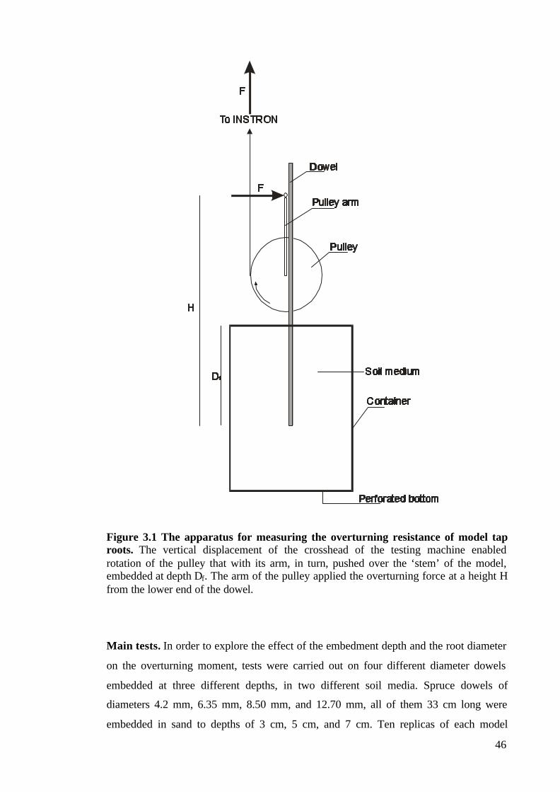
46
Figure 3.1 The apparatus for measuring the overturning resistance of model taproots. The vertical displacement of the crosshead of the testing machine enabledrotation of the pulley that with its arm, in turn, pushed over the ‘stem’ of the model,embedded at depth Df. The arm of the pulley applied the overturning force at a height Hfrom the lower end of the dowel.
Main tests. In order to explore the effect of the embedment depth and the root diameter
on the overturning moment, tests were carried out on four different diameter dowels
embedded at three different depths, in two different soil media. Spruce dowels of
diameters 4.2 mm, 6.35 mm, 8.50 mm, and 12.70 mm, all of them 33 cm long were
embedded in sand to depths of 3 cm, 5 cm, and 7 cm. Ten replicas of each model

47
diameter in each depth were pushed over and the maximum force was measured. Balsa
dowels of the same diameters as above, were embedded at 3 cm, 5 cm and 7 cm in
agricultural soil, ensuring that the low weight of the balsa wood would prevent the
models from falling down under their own weight. Ten replicas of each model at each
depth were tested, at the same time recording the maximum overturning force.
The overturning moment was calculated as a sum of the moment about its point of
rotation generated by the force applied through the pulley arm, and the moment that
resulted from the model’s own weight.
Statistical analysis. Two-way ANOVA was carried out for both the models in sand and
in agricultural soil in order to investigate the influence and significance of embedment
depth and root diameter as factors in the overall overturning resistance of the model.
The significance of any interaction between the two factors, was also tested.
In addition to this, log-log graphs of overturning moment against diameter and
overturning moment against embedment depth were produced, and linear regressions
were carried out for every model, to investigate how overturning moment was related to
the diameter and depth of embedment.
Theoretical analysis and scaling of anchorage. When an overturning force is applied
to a cylindrical tap-root model with radius R, and underground length Df, unconstrained
at both ends the failure can occur in two ways: either the tap breaks or it rotates through
the soil. For the models embedded in sand, engineering theory predicts that the rotation
will occur around a point very close to, or at the root tip itself, while for the models in
agricultural soil the rotation will occur around a point approximately Df/2 below the soil
surface. Since the dowel is effectively rigid, the soil will fail plastically and the theory
of earth piles (Broms 1964 a,b) can be used to calculate the forces required.
According to this theory the sand should resist overturning with a restoring moment Ms:
Ms=γDf 3Rkp (eqn 3.1)
Where, R is the model radius, γ is the unit weight of the sand, Df is the model’s
underground length and kp=(1+sinϕ)/(1-sinϕ) is the coefficient of passive earth pressure
and is a function of the angle of internal friction.
48
The agricultural soil should resist the sideways motion of the dowel with a force dF
acting on each small element of length dl:
dF= 18τRdl (eqn 3.2)
where τ is the shear strength of the cohesive soil. This should set up a restoring moment
dM:
dM=18τRldl (eqn 3.3)
where l is the distance of the element from the centre of rotation. The total moment in
agricultural soil Ma, resisting rotation is obtained by integrating dM over the half length
of the rod for the models:
Ma=9τRDf 2 (eqn 3.4)
The bending strength (Mb) of the tap-root is given by the equation:
Mb=πR3σ/4 (eqn 3.5)
where σ is the breaking stress of the root material, and is proportional to the cube of
root radius.
Since the amount of material required to resist a given overturning force is minimised
when the bending strength equals resistance to rotation in the respective soil type,
Mb=Ms and Mb=Ma. For the models in sand the optimal aspect ratio should be:
Df 3/R2=(πσ/4γkp) (eqn 3.6)
and for the models in agricultural soil the optimal aspect ratio should be:
Df2/R2=πσ/36τ (eqn 3.7)
Therefore for tap roots in sand one would predict that larger tap roots would be
relatively shorter, whereas in agricultural soils the optimal shape should be independent
of size.
3.3 RESULTS
3.3.1 Main Tests
The force against displacement curves showed that the overturning force increased
rapidly to an angle of approximately 15°, than plateaued and started to decline slowly.
This trend was recorded both for the models in sand and in agricultural soil.
Models in sand: mechanical tests showed a significant (F1,119=15.373, p<0.001) trend
of increase of the overturning moment with the embedment depth. All of the models

49
showed their maximum resistance at the 7 cm depth (Figure 3.2). The recorded
overturning moment ranged from 1.374 Nm for the smallest diameter model, to 2.173
Nm for the model with 8.05 mm diameter. Linear regression through logM vs. logDf
(Figure 3.3) showed that the overturning moment increased approximately with the third
power of the embedment depth
log M=3.4097 log Df + 4.1597 (r2=0.99) (eqn 3.8)
Exponents ranged from 2.873 for the smallest diameter, to 3.467 for the largest
diameter, none of them being significantly different from 3.
Figure 3.2 Overturning resistance of tap root models of four different sizes (D1=4.2mm, D2=6.35mm, D3=8.50 mm, D4=12.70 mm) in three different depths (3 cm, 5cm, and 7 cm) in sand. Error bars indicate + SE.
Figure 3.3 Log-Log dependency between the overturning moment (M) and theembedment depth (Df). Results for the tap root models of four different sizes (D1=4.2mm, D2=6.35 mm, D3=8.50 mm, D4=12.70 mm) embedded at three different depths (3cm, 5 cm, and 7 cm) in sand.
0
0.4
0.8
1.2
1.6
2
2.4
2.8
3cm 5cm 7cmDepth
Ove
rtur
ning
res
ista
nce
[N]
D1
D2
D3
D4
-1.2
-0.8
-0.4
0
0.4
-1.6 -1.4 -1.2 -1
Log [Df]
Log
[M]
D1
D2
D3
D4

50
The effect of the diameter (D=2R) was also significant (F1,119=585.412, p<0.001), but
not as highly as the effect of depth. It can be seen on Figure 3.2 that the overturning
resistance of the models increased with their diameter up to a certain point, and then
decreased again. At the shallowest depth of 3cm, the models with smallest diameter
performed best, reaching a moment of 0.1255 Nm, while the largest diameter models
had the poorest resistance – only 0.0692 Nm. On the other hand, at 7 cm, the resistance
reached its maximum with 8.50 mm diameter models, decreasing again for 10.8 mm
models.
Regression lines for the logM vs. logD graph (Figure 3.4) showed that the overturning
moment increased approximately with the 0.1 power of the model diameter
log M = 0.089 log D – 0.5387 (r2=0.37) (eqn 3.9)
slopes ranging from –0.036 to 0.320. None of the lines had a slope significantly
different from 0.
Figure 3.4 Log – Log dependency between the overturning moment (M) and themodel diameter (D). Results for tap root models with four different diameters (D1=4.2mm, D2=6.35 mm, D3=8.50 mm, D4=12.70 mm) embedded at three different depths (3cm, 5 cm, and 7 cm) in sand.
The interaction between embedment depth and model diameter was also significant
(F1,119=19.506, p<0.001). It is shown on Figure 3.4 that the rate of increase of the
overturning resistance was greatest for the models with diameter 8.50 mm when the
embedment depth increased from 3 cm to 5 cm, and was greatest for the model with
12.7 mm diameter when the depth increased from 5 cm to 7 cm.
-1.5
-1-0
.50
0.5
1
-2.5 -2.3 -2.1 -1.9 -1.7
log[D]
log[
M]
3cm depth
5cm depth
7cm depth

51
Models in agricultural soil: the main tests for the models in agricultural soils showed
that, as in the sand medium, the overturning resistance rose significantly (F1,119=507.42,
p<0.001) with the embedment depth. Calculated overturning moments (Figure 3.5)
ranged from 0.159 Nm at the 3 cm depth, to 4.222 Nm at the 7 cm depth. As in sand, the
resistance increased with the depth for every model diameter, always having the
maximum resistance at 7 cm depth. Models with the 12.7 mm diameter resisted
overturning the best at all depths, usually followed by the 8.50 mm diameter models.
Figure 3.5 Overturning resistance of tap root models of four different sizes (D1=4.2mm, D2=6.35mm, D3=8.50 mm, D4=12.70 mm) in three different depths (3 cm, 5cm, and 7 cm) in agricultural soil. Error bars indicate + SE.
Unlike the models in sand, the linear regression through logM vs. logDf (Figure 3.6)
showed that the resistance to overturning increased only approximately with the second
power of the embedment depth
log M=2.1526 log Df + 2.7458 (r2=0.86) (eqn 3.10)
Slopes ranged from 1.896 for 4.2 mm diameter models, to 2.734 for the models with
diameter 12.7 mm. None of these slope lines were significantly different from 2.
Model diameter was also a significant (F1,119=43.707, p<0.001) factor in overturning
resistance of the models in agricultural soil, although not as much as the depth. It can be
seen on Figure 3.5 that the smaller diameters (4.2 mm and 6.35 mm) showed very
similar resistances in all depths, but the smallest diameter models always performed
better than the models with 6.35 mm diameter. However, the largest diameter resisted
0
1
2
3
4
5
6
3cm 5cm 7cmDepth
Ove
rturn
ing
resi
stan
ce [N
]
D1
D2
D3
D4
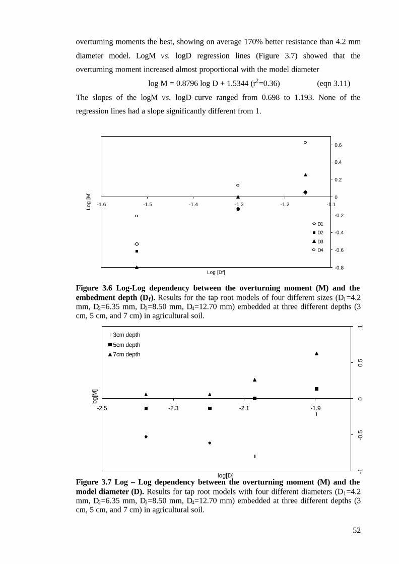
52
overturning moments the best, showing on average 170% better resistance than 4.2 mm
diameter model. LogM vs. logD regression lines (Figure 3.7) showed that the
overturning moment increased almost proportional with the model diameter
log M = 0.8796 log D + 1.5344 (r2=0.36) (eqn 3.11)
The slopes of the logM vs. logD curve ranged from 0.698 to 1.193. None of the
regression lines had a slope significantly different from 1.
Figure 3.6 Log-Log dependency between the overturning moment (M) and theembedment depth (Df). Results for the tap root models of four different sizes (D1=4.2mm, D2=6.35 mm, D3=8.50 mm, D4=12.70 mm) embedded at three different depths (3cm, 5 cm, and 7 cm) in agricultural soil.
Figure 3.7 Log – Log dependency between the overturning moment (M) and themodel diameter (D). Results for tap root models with four different diameters (D1=4.2mm, D2=6.35 mm, D3=8.50 mm, D4=12.70 mm) embedded at three different depths (3cm, 5 cm, and 7 cm) in agricultural soil.
-0.8
-0.6
-0.4
-0.2
0
0.2
0.4
0.6
-1.6 -1.5 -1.4 -1.3 -1.2 -1.1
Log [Df]
Lo
g [
M]
D1
D2
D3
D4
-1-0
.50
0.5
1
-2.5 -2.3 -2.1 -1.9
log[D]
log[
M]
3cm depth
5cm depth
7cm depth

53
Models in agricultural soil also showed a significant (F1,119=26.576, p<0.001)
interaction between embedment depth and model diameter. Just as in sand, the rate of
increase of the overturning resistance was greatest for the models with 8.50 mm.
3.3.2 Mechanical Analysis and Scaling of Anchorage
The regression line through the logM vs. log Df graph for the models embedded in sand
showed that the overturning moment M is a function of approximately the third power
of the embedment depth (eqn 3.8), while for the models in agricultural soil the
overturning moment changes with the second power of the embedment depth (eqn
3.10).
On the other hand, the regression line through logM vs. logD graph showed that the
overturning moment for the tap root models in cohesive soil increased with the first
power of D, while the influence of D on the overturning moment on model tap roots in
cohesionless soil was negligible.
These results show that lateral resistance of resistance of the tap root to rotation through
the soil in sand (Ms) and in agricultural soil (Ma) can be given by the equations:
Ms ∝ C1 Df3 for cohesionless soils and, (eqn 3.12)
Ma ∝ C2 RDf2 for cohesive soils (eqn 3.13)
where C1 and C2 are constants.
These are similar to the Broms’ equations (3.1 and 3.4) except that for cohesionless soil
the radius of the tap root has no effect on the overall resistance to overturning.
The optimal aspect ratio of a tap root when its bending strength (eqn 3.5) equals its
resistance to rotation through the soil (eqns 3.12 and 3.13, respectively) is therefore:
Df3/R3 = const. for cohesionless soil and, (eqn 3.14)
Df2/R2 = const. for cohesive soils (eqn 3.15)

54
It is clear that for both types of soil the optimal aspect ratio Df/R is constant, i.e. in order
to have minimal investment of material resisting given overturning force, an increase in
the tap root diameter will require a proportional increase of its embedment depth.
3.4 DISCUSSION
The test method designed for this study worked well, and several points became
apparent.
Overturning tests on our models revealed differences between the mechanism of
anchorage failure in the cohesionless media and the one in the cohesive media (Figure
3.8). This is mostly due to the fact that in cohesive soils the soil has shear strength, even
on the surface, whereas in sand it increases with the depth because of the weight of the
overburden.
a) b)
Figure 3.8 The mechanism of anchorage failure under horizontal overturning force(Hu) in a) cohesionless and b) cohesive media. Soil shear strength (soil reaction)increases with depth in cohesionless soil, while in cohesive soils it exists even close tothe soil surface. The model tap root rotates around a point close to the root tip incohesionless soil, and around a point between the root tip and the soil surface incohesive soil.
In many ways the results of this study agree with engineering theory. They showed that
the overturning resistance of the model tap roots increased with the third and second
power of the embedment depth, in sand and in agricultural soil respectively, as
predicted by the pile models of Broms (1964 a,b). In this respect the behaviour of our

55
models under lateral loading is comparable to the behaviour of laterally loaded rigid
piles in engineering (Broms 1964 a,b; Poulos and Davis 1980). Furthermore, these
results are also in accordance with the ones predicted in the theoretical models of
anchorage by Ennos (1993). The investigations of Goodman et al. (2001) showed that in
their agricultural soil the resistance to overturning increased with an intermediate power
of the depth, 2.53. This was, probably due to a presence of a relatively large sand
fraction in the agricultural soil, which made it behave somewhere between cohesionless
and cohesive soil.
Despite all the similarities in the behaviour of our models with the behaviour of laterally
loaded piles (Broms 1964 a,b) and theoretical models of anchorage (Ennos 1993), there
were some results for the models in cohesionless soil, which did not agree with the
engineering theory (Broms 1964 a,b). In sharp contrast to the cases in agricultural soil,
there was little consistent increase of overturning moment with model diameter. The
resistance of the models to overturning increased approximately linearly with the root
diameter in agricultural soil, but in sandy soils, as in the models of Goodman et al.
(2001), the resistance to overturning was practically independent of the model diameter.
This finding contradicts the engineering theory where the overturning moment of rigid
piles in cohesive soils is proportional to the root diameter. The discrepancy between the
predicted and measured values probably comes from the size of the models – the models
in this study were far smaller than the ones used when deriving the engineering theory
of laterally loaded piles (Broms 1964 a,b). In this manner, the behaviour of our models
could be compared to that of the narrow tines used in agricultural engineering (Spoor
1973, Goodman et al. 2001) whose depth is far more important than their size in
influencing resistance to movement through soil.
What significance do these findings have for root system design? The most important
fact to note from the results of this study might be the strong dependency of the
overturning moment on the embedment depth, both in cohesive and cohesionless soil. It
is clear that for the plant the best way to increase anchorage strength is to extend a rigid
root to the largest possible depth thus maximising the anchorage strength with minimum
investments in structural material. However, the size and shape of the tap root is limited
by strength considerations (Ennos 1993), and depending on those, two different types of
failure under lateral loads would be possible: soil failure, in which the strength of the

56
tap root exceeds the soil strength, or root failure in which the soil resistance is greater
than the root strength (Figure 3.9).
a) b)
Figure 3.9 Two possible types of root failure under horizontal lateral loads (Hu). a)Soil failure: the tap root rotates in the soil since its strength is greater than the soilstrength and, b) Root failure: tap root breaks under the load forming plastic hinge sincethe resistance of the surrounding soil is greater than the strength of the root.
Assuming that the soil failure would occur before the tap root fails, the deepest position
of a rigid root will provide safe anchorage even for a tall plant under heavy lateral loads
such as winds. However, for some tap rooted species, especially for the desert species
which favour water and nutrient acquisition over stability, it is hard to invest a large
amount of root material at greater depths (Rundel and Nobel 1991, Niklas et al. 2002),
and failing to do so, they become vulnerable to lateral loads. Thick but short tap roots
are often a cause for failure under lateral loads also in pines (Stokes 1999), especially in
winter, when soil cohesion is reduced. In order to become more stable under lateral
loads it would be more economical for the plant to split the large rigid root into a group
of several deeply embedded thinner tap roots with a larger surface area, as in the desert
tree Prosopis glandulosa (Rundel and Nobel 1991). This adaptation could be
accompanied by the positioning of the tap roots at a certain angle from the vertical – a
position that will enable them to endure compression or tension, depending on the
orientation of the current loads, instead of enduring only bending. This type of
adaptation is commonly seen in some species of desert shrubs, whose laterals emerge
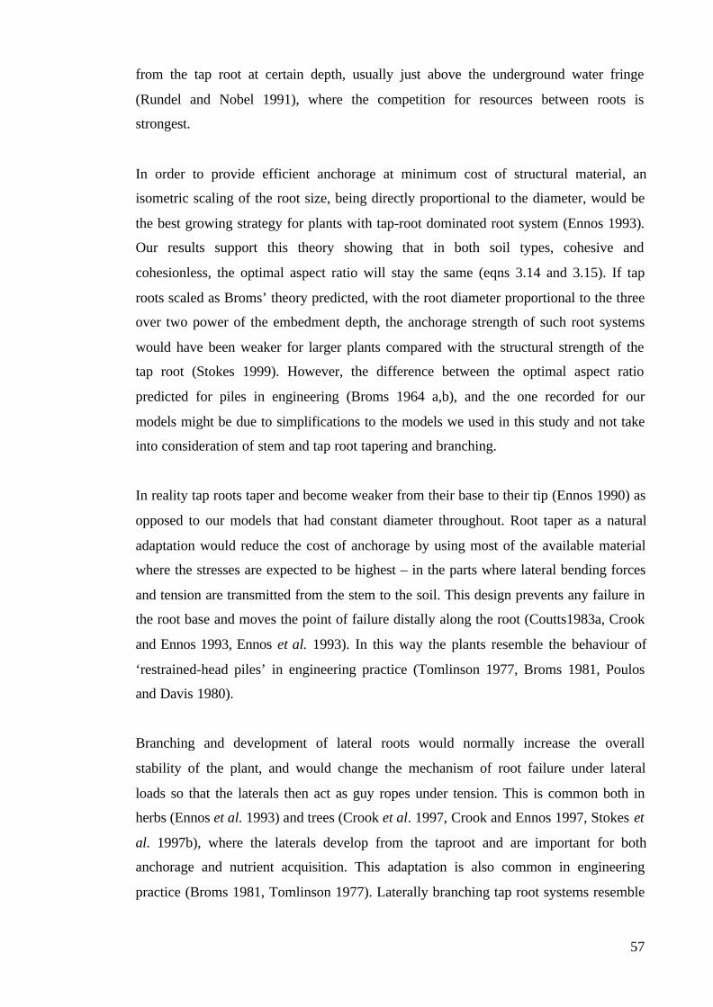
57
from the tap root at certain depth, usually just above the underground water fringe
(Rundel and Nobel 1991), where the competition for resources between roots is
strongest.
In order to provide efficient anchorage at minimum cost of structural material, an
isometric scaling of the root size, being directly proportional to the diameter, would be
the best growing strategy for plants with tap-root dominated root system (Ennos 1993).
Our results support this theory showing that in both soil types, cohesive and
cohesionless, the optimal aspect ratio will stay the same (eqns 3.14 and 3.15). If tap
roots scaled as Broms’ theory predicted, with the root diameter proportional to the three
over two power of the embedment depth, the anchorage strength of such root systems
would have been weaker for larger plants compared with the structural strength of the
tap root (Stokes 1999). However, the difference between the optimal aspect ratio
predicted for piles in engineering (Broms 1964 a,b), and the one recorded for our
models might be due to simplifications to the models we used in this study and not take
into consideration of stem and tap root tapering and branching.
In reality tap roots taper and become weaker from their base to their tip (Ennos 1990) as
opposed to our models that had constant diameter throughout. Root taper as a natural
adaptation would reduce the cost of anchorage by using most of the available material
where the stresses are expected to be highest – in the parts where lateral bending forces
and tension are transmitted from the stem to the soil. This design prevents any failure in
the root base and moves the point of failure distally along the root (Coutts1983a, Crook
and Ennos 1993, Ennos et al. 1993). In this way the plants resemble the behaviour of
‘restrained-head piles’ in engineering practice (Tomlinson 1977, Broms 1981, Poulos
and Davis 1980).
Branching and development of lateral roots would normally increase the overall
stability of the plant, and would change the mechanism of root failure under lateral
loads so that the laterals then act as guy ropes under tension. This is common both in
herbs (Ennos et al. 1993) and trees (Crook et al. 1997, Crook and Ennos 1997, Stokes et
al. 1997b), where the laterals develop from the taproot and are important for both
anchorage and nutrient acquisition. This adaptation is also common in engineering
practice (Broms 1981, Tomlinson 1977). Laterally branching tap root systems resemble

58
vertical piles which have added lateral wing or beam structures to increase their lateral
stability.
An improved knowledge of the anchorage mechanics of rigid tap root dominated root
systems is needed. This can only be achieved by an extension of the number of species
studied, which will help in explaining the root system variability in form and function.
Furthermore, an investigation of the behaviour of tap root system in the same species
grown in different environmental conditions (different temperature, soil type, light
levels, water and nutrient availability) is needed in order to explore the effects of the
environmental conditions on the development of the root system growth strategy,
allometry and scaling.

59
CHAPTER FOUR: THE INFLUENCE OF SOIL COMPACTION
AND TEMPERATURE ON THE GROWTH AND THE
DEVELOPMENT OF ROOT SYSTEMS IN TWO PINUS SPECIES
For pines are gossip pines the world wide throughAnd full of runic tales to sigh or sing…
James Elroy Flecker (1884-1915) Golden Journey to Samarkand
4.1 INTRODUCTION
Two of the principal soil physical factors that affect root growth are its mechanical
strength and temperature. Soil compaction, which results in mechanical impedance that
might restrict root growth, mainly arises from externally applied forces such as
trampling by animals or farm and tillage equipment. Consequently, the effects of
mechanical impedance on root growth have been reviewed extensively by Barley and
Graecen (1967), Taylor et al. (1972), Russel (1977), Graecen (1986), Bengough and
Mullins (1990), Glinski and Lipiec (1990), and Bennie (1996). Of all stresses associated
with germination, plant and root establishment and development, temperature stress is
most common. Soil temperature changes can have significant effects on the growth and
development of the root systems as discussed in Brouwer and Hoagland (1964), Cooper
(1973), Nielsen (1974), Glinski and Lipiec (1990), Bowen (1991), and McMichael and
Burke (1996).
Mechanical impedance is experienced to different degrees by all roots growing through
soil. It refers to the resistance of the soil matrix against deformation by the growing
root, permitting root elongation the extent of which depends on how much root pressure
exceeds the mechanical impedance (Bennie 1996). Root growth is further impeded by
low aeration which is a result of soil compaction (McMichael and Burke 1996).
Results of previous studies have shown that the root elongation rate of different species
(corn - Barley 1963; peas - Graecen et al. 1968, Dexter 1987; cotton and peanuts -
Taylor and Ratliff 1969; sunflower - Plaut et al. 1996) decreases with increased soil
resistance. Eavis (1967) reported that the root elongation rate in peas was reduced by
50% at applied pressure of 0.3 MPa, while Bengough and Mullins (1988) found out that
a pressure of 0.39 to 0.48 MPa reduces root growth in maize by 50 to 90%. On the other
hand, Goss and Russel (1980) found out that the elongation rate of barley roots
encountering very small mechanical resistance can decrease transiently by a large
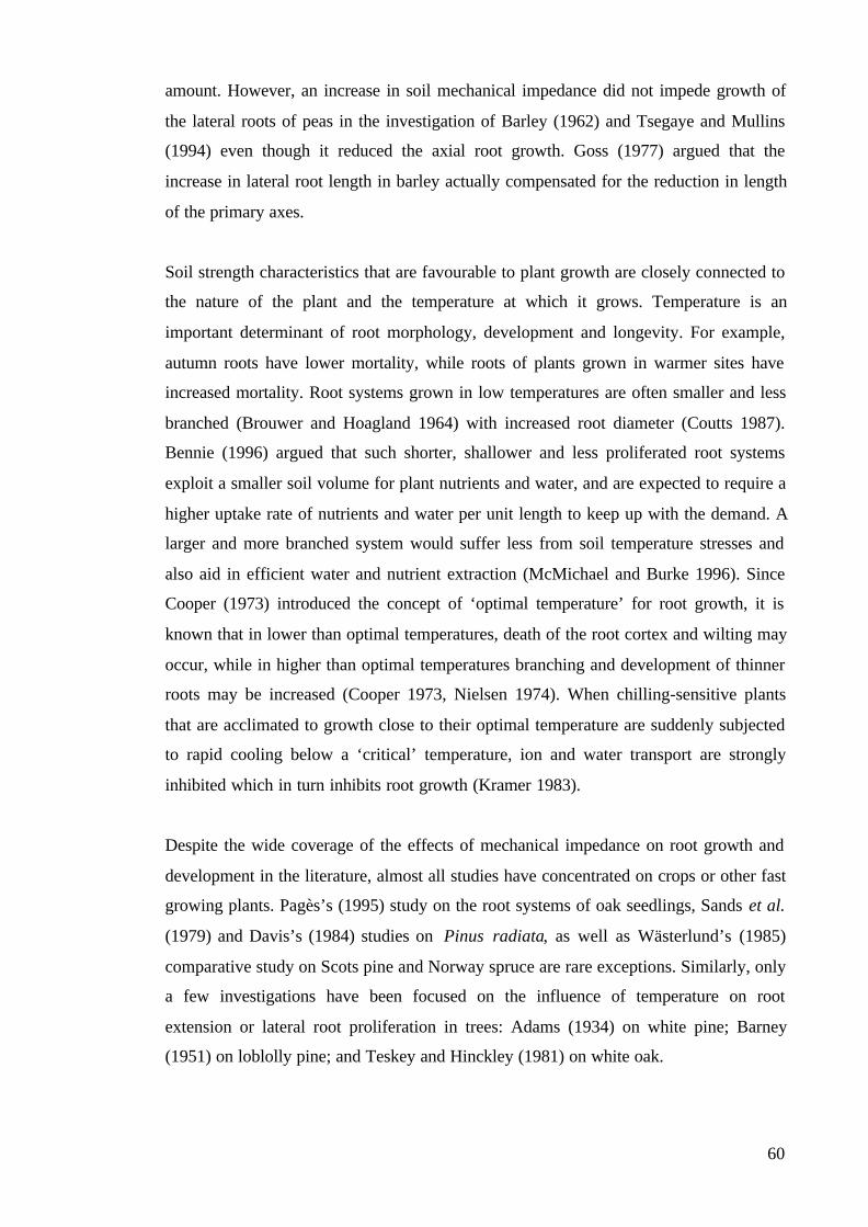
60
amount. However, an increase in soil mechanical impedance did not impede growth of
the lateral roots of peas in the investigation of Barley (1962) and Tsegaye and Mullins
(1994) even though it reduced the axial root growth. Goss (1977) argued that the
increase in lateral root length in barley actually compensated for the reduction in length
of the primary axes.
Soil strength characteristics that are favourable to plant growth are closely connected to
the nature of the plant and the temperature at which it grows. Temperature is an
important determinant of root morphology, development and longevity. For example,
autumn roots have lower mortality, while roots of plants grown in warmer sites have
increased mortality. Root systems grown in low temperatures are often smaller and less
branched (Brouwer and Hoagland 1964) with increased root diameter (Coutts 1987).
Bennie (1996) argued that such shorter, shallower and less proliferated root systems
exploit a smaller soil volume for plant nutrients and water, and are expected to require a
higher uptake rate of nutrients and water per unit length to keep up with the demand. A
larger and more branched system would suffer less from soil temperature stresses and
also aid in efficient water and nutrient extraction (McMichael and Burke 1996). Since
Cooper (1973) introduced the concept of ‘optimal temperature’ for root growth, it is
known that in lower than optimal temperatures, death of the root cortex and wilting may
occur, while in higher than optimal temperatures branching and development of thinner
roots may be increased (Cooper 1973, Nielsen 1974). When chilling-sensitive plants
that are acclimated to growth close to their optimal temperature are suddenly subjected
to rapid cooling below a ‘critical’ temperature, ion and water transport are strongly
inhibited which in turn inhibits root growth (Kramer 1983).
Despite the wide coverage of the effects of mechanical impedance on root growth and
development in the literature, almost all studies have concentrated on crops or other fast
growing plants. Pagès’s (1995) study on the root systems of oak seedlings, Sands et al.
(1979) and Davis’s (1984) studies on Pinus radiata, as well as Wästerlund’s (1985)
comparative study on Scots pine and Norway spruce are rare exceptions. Similarly, only
a few investigations have been focused on the influence of temperature on root
extension or lateral root proliferation in trees: Adams (1934) on white pine; Barney
(1951) on loblolly pine; and Teskey and Hinckley (1981) on white oak.

61
Previous investigations have been conducted by simulating field conditions in soil
columns or ballotini (Barley 1962; Goss 1977), but have rarely been carried out in a
natural environment (Goss 1977).
This study is an attempt to investigate the root development of two Pinus species,
grown in different soil compaction levels and temperatures and to explore the influence
of temperature and soil compaction on the axial and lateral root development. The
results of this study might deepen our knowledge on the most important factors
influencing root development in the early stages of growth, and will surely add to the
number of new tree species investigated.
4.2 MATERIALS AND METHODS
4.2.1 Seedlings
90 Pinus sylvestris and 90 Pinus peuce seedlings were supplied from the Pelister
National Park Nursery in Resen, Macedonia. The seedlings of each species were
collected from a same tree and were 1 year old at the time they were planted.
4.2.2 Soil
Brown spongy organic clay (Norbury et al. 1986) with amorphous structure (provided
by The Soil Station, Faculty of Forestry, Sts Cyril and Methodius University, Skopje,
Macedonia) with dry bulk density of ρd=1.26 Mg m-3 was used throughout this
investigation.
4.2.3 Soil Preparation and Planting
The seedlings were planted in plastic containers 25 cm x 80cm x 30 cm. Planting ten
seedlings in each container (Figure 4.1) enabled their root systems to develop without
interfering with each other.
62
Figure 4.1 Pine seedlings planted in plastic containers (side and top view). This wayof planting enabled unimpeded development and growth of their root systems.
For each species, three containers labelled ‘compacted soil’ were prepared for planting
by laying a soil layer of approximately 15 cm at the bottom of the container, compacting
it, planting the seedlings and adding another 15 cm thick layer of soil. The soil was then
watered and compacted with a standard compaction hammer (6 cm x 6 cm compacting
area, related to BS 1377:Part2:1990:7.2) applying a force of 8 N to the whole soil
surface.
Another three containers labelled ‘semi-compacted soil’ for each species were prepared
by laying a loose soil layer of approximately 15 cm at the bottom of the container,
planting the seedlings, and adding another 15 cm of soil. The soil was than watered and
compacted with the same compaction hammer applying a force of 4 N to the whole soil
surface.
The last three containers labelled ‘loose soil’ were prepared for planting by laying a soil
layer of cca. 15 cm at the bottom of the container, planting the seedlings and adding
another 15 cm thick layer of soil, ensuring that no compaction of the soil occurred.
Finally, the soil was watered.
The containers were then put in one of three separate glasshouse cubicles at the Faculty
of Forestry, Sts Cyril and Methodius University, Skopje, Macedonia. Each of the three
cubicles was kept at a constant temperature (15°C, 20°C, and 25°C respectively).
Containers were arranged so that there were ten seedlings of each species in compact,
semi-compact and loose soil at each of the three different temperatures.
80 cm
25 c
m3
0 cm
14 cm
9 cm
9 c
m
12
cm
14 cm

63
4.2.4 Penetrometer Resistance
A pocket penetrometer (TP1, Wille Geotechnik, Germany) equipped with cylindrical
needle with a 2 mm diameter was used to determine the soil resistance to penetration in
laboratory conditions. The resistance of the soil to static penetration was tested at four
different depths: 2.5 cm, 5 cm, 7.5 cm, and 10 cm. The soil layer investigated was
cleared and measuring spots with a smooth surface were selected carefully, enabling the
tip of the penetrometer to have better adhesion to the soil. Probes were taken at 12
measuring spots at each layer in each container. The penetrometer was held tight and at
right angles to the surface being tested, and a pressure was applied so that the tip of the
penetrometer entered the soil at a rate of about 5 mm min-1. A sliding ring on the barrel
of the penetrometer gave the maximum reading of the resistance, measured in kPa.
4.2.5 Root System Measurements
The root system architecture and distribution of the seedlings was recorded before
planting, together with the maximum axial length of the root system, the number of
‘major’ laterals (defined as lateral roots longer than 2 cm) per seedling, and the root
diameter 5 cm below the root apex of every seedling. The lengths were measured with a
ruler and the diameter with engineering callipers.
The seedlings were investigated and new measurements taken every 14 days. The soil
was gently removed from around every plant, the seedling being carefully handled
while the smaller soil crumbs were removed from the roots with a pair of fine forceps.
The axial root length was then measured with a ruler and the number of major laterals
was recorded. The root diameter 5 cm below the root apex was measured with callipers
only at harvest, ensuring as little disturbance to the roots as possible. After this, the
planting procedure was repeated to give the same soil consistency, and the seedlings
were watered with the same amount of water.
The investigation was carried out in the spring of 2001 when maximum growth rates
were expected.

64
4.2.6 Statistical Methods
The rate of axial elongation of the root system in cm day-1 for each plant was calculated
by subtracting the axial root length measured at the beginning of the experiment from
that measured at harvest, and then dividing by the length of the experiment (84 days).
The axial root elongation of every seedling was plotted over time and the slope of every
growth curve was calculated.
For both species, the increase in the number of major lateral roots was calculated by
subtracting the number of major laterals before the experiment from that at harvest.
Analysis of variance (ANOVA) was then used to calculate the significance of different
factors (species, temperature, soil consistence) on the axial root growth of the seedlings,
as well as on the increase of the number of major laterals over time.
4.3 RESULTS
4.3.1 Penetrometer Resistance
Results of the penetrometer tests are shown in Figure 4.2. Two trends were evident;
First, the soil resistance to penetration increased with the depth. Penetrometer resistance
of the soil prepared as described in the Materials and Methods section ranged from
0.981 kPa for loose soil at 2.5 cm depth, to 25.01 kPa for compact soil at 10 cm depth
(Figure 4.2).
Figure 4.2 Penetrometer resistance at four different soil depths (2.5 cm, 5 cm, 7.5cm, and 10 cm) for the three types of soil consistency (loose, semi-compact and,compact).
0
5
10
15
20
25
30
-2.5 -5 -7.5 -10
Depth [cm]
Pe
ne
tro
me
ter
Re
sist
an
ce [
kPa
]
Loose soil
Semi-compact soil
Compact soil

65
Second, the greatest differences in soil consistency were found in the uppermost layers
of the soil where the majority of roots were located. These levels of soil compactness
were far from the maximum compactness levels (Barley and Graecen 1967; Bengough
and Mullins 1990) which prohibit root growth.
4.3.2 Root System Architecture and Distribution
The visual observations on the root system architecture in the seedlings of P. peuce and
P. sylvestris suggested an overall difference between species in the root form and
distribution. The roots of the P. peuce seedlings consisted of brown, thicker and shorter
first and second order laterals (Plate 4.1a), whereas prominent third order laterals were
also visible in the root systems of P. sylvestris, originating from yellow-brown, thinner
and longer first and second order laterals (Plate 4.1b).

66
a)
b)
Plate 4.1 The morphology and architecture of one-year-old a) P. peuce and b) P.sylvestris. The root system of young P. sylvestris was more proliferated, with longer andthinner laterals, while the root system of P. peuce had thicker and shorter laterals

67
The maximum axial length of the root systems measured before planting (Figure 4.3)
ranged from 4.9 cm to 24.9 cm, and was on average 12.26±1.91 cm (throughout this
chapter, mean ± SD) for P. sylvestris, not significantly (p=0.129) different from the
average of 13.88±4.72 cm for P. peuce.
Figure 4.3 Average maximum root axial length in both Pinus sylvestris and Pinuspeuce seedlings at the start and at the end of the experiment. The axial length of theroots system in both species increased during the experiment but was more dramatic inPinus peuce. Error bars indicate mean + SD.
Having an average of 4.34±1.32 major lateral roots at the time of planting (Figure 4.4),
the root system of P. peuce was significantly (t=2.765, p=0.005) simpler and less
laterally proliferated than the root system of P. sylvestris seedlings that had 5.14±0.98
major laterals.
0
2
4
6
8
10
12
14
16
18
20
P. sylvestrisP. peuce
Species
Axialrootlength[cm]
At planting
At harvest

68
Figure 4.4 Average number of major lateral roots in Pinus sylvestris and Pinuspeuce seedlings at the start and at the end of the experiment. The number of majorlaterals increased in both species during the experiment but was more dramatic in Pinuspeuce. Error bars indicate mean + SD.
4.3.3 Axial Root Elongation
During the investigation, all of the seedlings of both species showed a steady increase in
the axial length of their root systems throughout the experiment. Roots were longest at
harvest. This justifies the method of control and measurement during growth, since no
apparent damage had been done to the roots to inhibit their growth.
The axial length of P. peuce seedlings at harvest ranged from 5.0 cm to 25.5 cm, or
14.582±4.02 cm for the whole population (Figure 4.3). This was not significantly
(p>0.05) different from the axial length of P. sylvestris root systems that ranged from
7.9 cm to 21.2 cm, or 13.567±1.99 cm on average for the whole population.
The growth rate (Figure 4.5a,b) was affected by three factors: the species, degree of soil
compaction, and temperature. The average rate of axial growth for P. sylvestris
seedlings was 0.142±0.024 mm day-1, which was as one-way ANOVA showed,
significantly (F1,178=16.742, p<0.001) higher than the rate of axial growth for P. peuce
of 0.077±0.0243 mm day-1.
0
1
2
3
4
5
6
7
8
9
P. sylvestris P. peuce
Species
Num
ber
of L
ater
als
At planting
At harvest

69
a)
b)
Figure 4.5 Average axial root growth rate of a) Pinus sylvestris and b) Pinus peuceseedlings grown at three different temperatures (15°°C, 20°°C, and 25°° C) and inthree different soil consistencies (loose, semi-compact and, compact). Error barsindicate + SD.
Two-way ANOVA showed that soil consistency had a significant effect on the axial
root growth in P. peuce (F1,178=28.341, p<0.001), but not in P. sylvestris (p=0.741), the
growth rate being highest in loose soil and lowest in the compact soil in the former
species.
0
0.05
0.1
0.15
0.2
0.25
15°C 20°C 25°CTemperature
[mm
/day
]
Loose soil
Semi-compact soil
Compact soil
0
0.05
0.1
0.15
0.2
0.25
15°C 20°C 25°CTemperature
[mm
/day
]
Loose soil
Semi-compact soil
Compact soil

70
Two-way ANOVA showed that the growth temperature had a significant effect on the
axial growth of both P. peuce and P. sylvestris seedlings (F1,178=7.232, p=0.004 and
F1,178=7.014, p=0.012, respectively). The seedlings grown at 15°C had greatest mean
increase in the axial length of their roots for both species, followed by the ones grown at
20°C and at 25°C which had elongated least of all.
The two-way ANOVA also showed that there was no significant interaction (p>0.05)
between temperature and soil consistency in either species.
4.3.4 Lateral Root Proliferation
Lateral root proliferation in this experiment was measured as the increase in the number
of ‘major’ lateral roots during the investigation. Major lateral roots were defined as
first-order lateral roots longer than 2 cm. 81 out of 90 (90%) of the P. peuce seedlings,
and 84 out of 90 (93%) P. sylvestris seedlings proliferated new major laterals during the
investigation. The average number of laterals at harvest was 6.022±0.213 for P. peuce
seedlings, which was significantly (F1,178=22.315, p<0.001) lower than the average
number of major laterals for P. sylvestris seedlings: 7.156±0.183 (Figure 4.3).
The number of major laterals proliferated during the investigation varied between 1 and
4 for P. peuce, and between 1 and 5 for P. sylvestris seedlings. One-way ANOVA
showed that the average increase in the number of new major laterals for P. peuce
seedlings was 1.697±0.105, which was significantly (F1,178=7.014, p=0.012) lower than
the average increase in the number of major laterals for P. sylvestris: 2.011±0.055.
The increase in the number of major lateral roots is shown in Figure 4.6a,b. A two-way
ANOVA showed that soil compaction had no significant (p>0.05) effect in either P.
sylvestris or P. peuce.

71
a)
b)
Figure 4.6 Average increase in the number of major lateral roots in a) Pinussylvestris and b) Pinus peuce at three different temperatures (15°°C, 20°°C and,25°° C) in three different consistencies (loose, semi-compact and, compact). Errorbars indicate + SD.
0
0.5
1
1.5
2
2.5
3
3.5
15°C 20°C 25°CTemperature
Ave
rag
e la
tera
ls p
er
tre
e
Loose soil
Semi-compact soil
Compact soil
0
0.5
1
1.5
2
2.5
3
15°C 20°C 25°CTemperature
Ave
rag
e la
tera
ls p
er
tre
e
Loose soil
Semi-compact soil
Compact soil
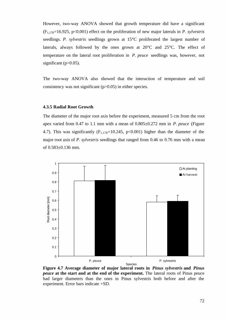
72
However, two-way ANOVA showed that growth temperature did have a significant
(F1,178=16.925, p<0.001) effect on the proliferation of new major laterals in P. sylvestris
seedlings. P. sylvestris seedlings grown at 15°C proliferated the largest number of
laterals, always followed by the ones grown at 20°C and 25°C. The effect of
temperature on the lateral root proliferation in P. peuce seedlings was, however, not
significant (p>0.05).
The two-way ANOVA also showed that the interaction of temperature and soil
consistency was not significant (p>0.05) in either species.
4.3.5 Radial Root Growth
The diameter of the major root axis before the experiment, measured 5 cm from the root
apex varied from 0.47 to 1.1 mm with a mean of 0.805±0.272 mm in P. peuce (Figure
4.7). This was significantly (F1,178=10.245, p<0.001) higher than the diameter of the
major root axis of P. sylvestris seedlings that ranged from 0.46 to 0.76 mm with a mean
of 0.583±0.136 mm.
Figure 4.7 Average diameter of major lateral roots in Pinus sylvestris and Pinuspeuce at the start and at the end of the experiment. The lateral roots of Pinus peucehad larger diameters than the ones in Pinus sylvestris both before and after theexperiment. Error bars indicate +SD.
0
0.1
0.2
0.3
0.4
0.5
0.6
0.7
0.8
0.9
1
P. peuce P. sylvestrisSpecies
Roo
t dia
met
er [m
m]
At planting
At harvest

73
An increase in the diameter of the major root axes was recorded in 54 out of 90 (61%)
of the P. peuce seedlings and in 49 out of 90 (54%) of the P. sylvestris seedlings. The
diameter increase varied between 0.01 and 0.02 mm for both species.
At harvest the diameter of the major root axis of P. peuce was 0.814±0.341 mm on
average, and was still significantly higher than the diameter of the major root axis of P.
sylvestris seedlings: 0.591±0.287 mm.
The rates of increase of radial root diameter showed a tendency to increase with
increase in the soil compactness and temperature, but the one- and two-way ANOVA
showed that this was not statistically significant (p>0.05).
4.4 DISCUSSION
This study showed both similarities and differences in the root growth in two Pinus
species subjected to different soil consistencies and temperatures. The similarities lay in
the fact that both species had the largest increase in axial length of their root systems at
15°C, which might be due to the optimal temperature for root elongation rate, just as in
Quercus alba (Teskey and Hinckley 1981). Furthermore, in both species, soil
consistency had no significant effect on lateral root proliferation; lateral roots overcome
even the strongly compacted soil, which was in agreement with the results of Misra
(1997). The differences between the species lay in the rate of axial development of the
root systems. While the rate of axial growth of the root system in P. peuce decreased
with an increase in soil compaction, the same increase in soil compaction levels did not
significantly affect the rate of axial root growth in P. sylvestris. There were differences
between species in the extent of lateral root proliferation, as well. While P. sylvestris
proliferated fewer laterals as the temperature increased, the temperature seemed to be a
non-significant factor in the lateral root development of P. peuce seedlings.
This study showed that the root elongation rate in P. peuce is negatively correlated with
mechanical impedance of the soil, since the elongation was lowest in the compacted
media and increased as the soil compaction level decreased. However, soil compaction
did not have a significant effect on the axial root growth in P. sylvestris. The reduction
in axial growth due to increased levels of soil compaction in P. peuce is consistent with
the results of previous studies (Barley 1963, Graecen et al. 1968, Taylor and Ratliff
1969, Dexter 1987, Bengough and Mullins 1988, Plaut et al. 1996), even though the

74
levels of compaction in this study were well below the maximum roots are capable of
withstanding (for a review see Bengough and Mullins1990). The decrease of the axial
root elongation rate with the compaction in P. peuce might have resulted from a
reduction in the rate of cell elongation and possibly from a decrease in cell production
rate. It might also have been a result of a smaller difference between the cell pressure
and the resistance offered by the soil matrix (Dexter 1987).
One question is why soil compaction did not significantly influence or impede the axial
root growth of P. sylvestris seedlings. A reason for the lack of effect of compaction on
the root growth of P. sylvestris might lie in its smaller root diameter. Just as in the study
of Fayle (1975) who found that only the thinner roots of red pine had penetrated down
into soil layers of higher mechanical impedance, the growth of our P. sylvestris roots
was not impeded by increased soil compaction. The thinner and more branched roots of
P. sylvestris grew faster, and encountered less resistance while extending through the
gaps in the soil structure. This was in sharp contrast to the thicker roots of P. peuce
whose diameters were bigger than the voids between the soil structure units and had to
overcome the soil resistance to penetration (Bengough and Mullins 1990) during their
growth.
The answer to the question posed above might alternatively lie in the factors that were
outside the scope of this investigation. If the soil kept a higher soil-water potential
during the experiment, then the mechanical impedance of the soil might have decreased
(Graecen 1960, Payne 1973, Bennie 1996), thus offering less resistance to the
penetrating roots. Since a greater lateral proliferation was recorded for P. sylvestris
seedlings, and it is known that lateral root proliferation and branching increases with the
increase in soil water potential (Johnson and Aguirre 1991), this might also be a reason
for the unimpeded axial growth in P. sylvestris in different soil compaction levels.
Although P. sylvestris in general produced more major laterals than P. peuce during the
investigation, the soil compaction levels did not significantly influence proliferation of
new laterals in either species. This result supports the fact that lateral roots exert less
force to grow than primary roots but are still able to exploit smaller voids in the soil,
and to withstand stronger soils (Misra 1997). In the same study it was argued that there
might be a compensatory mechanism governing root system development in a sense that
when the primary root is suppressed, a larger lateral proliferation would occur helping
75
in acquiring resources and keeping up with the demand of the plant. In sharp contrast to
the root systems of pea and eucalypt (Misra 1997), which showed larger lateral
proliferation when their primary root is suppressed, our P. peuce seedlings whose axial
root growth was impeded by soil compaction did not manifest an increase in lateral root
proliferation.
Acknowledging the fact that the type of soil strength characteristics favourable to plant
growth depends on the species and the distribution of the temperature year round
(Bengough and Mullins 1990), it is important to consider the soil temperature as the
other factor that affected root growth in this experiment. Our results showed that both of
the species tend to have low optimal temperatures for axial growth and lateral
proliferation. Both of them being cool season plants, in this study they had their greatest
axial root growth at 15°C, which is lower than the optimal temperature of pines
originating in warmer climates, such as Pinus taeda (Barney 1951, McMichael and
Burke 1996) which showed maximum root growth at around 20°C. The lateral root
proliferation in P. sylvestris was highest at 15°C, while in P. peuce temperature did not
significantly affect lateral root proliferation. This means that the lateral proliferation in
P. peuce would not be restricted even during the hot and dry seasons in the Balkans,
although axial root growth will be highest in cooler seasons at temperatures of around
15°C. On the other hand, P. sylvestris seems to be adapted to lower temperatures,
showing maximum axial and lateral root growth at temperature of around 15°C.
What are the effect of these two factors on the overall growth of the root system and the
plant in general? The functioning of the roots developing under conditions of restricted
growth due to soil mechanical resistance can be severely obstructed in different ways.
The shorter, thicker and less proliferated systems such as the one in our P. peuce
seedlings would exploit a smaller soil volume for water and nutrients. Moreover, the
shorter root length and the lower rate of lateral proliferation would require the present
roots to maintain a higher-than-normal uptake rate of water and nutrients in order to
keep pace with the demand (Bennie 1991). This, in turn, would rapidly deplete the
surrounding soil having a negative effect on the water and nutrient uptake processes,
making the plant more susceptible to water or nutrient stress and eventually reduce its
growth.

76
Bearing in mind that the roots penetrate soil by an alternating series of radial and axial
enlargements (Abdalla et al. 1969), it is clear that they have to overcome soil
mechanical resistance in both the axial and radial direction, and/or adapt and change
physiologically to the stresses encountered as argued by Bengough and Mullins (1990).
The average elongation rate of the roots in the trees in this study was 0.3 cm per month,
though Pinus sylvestris seedlings showed much faster root growth, which was similar to
that found by Coutts (1983) in Picea sitchensis. A very slow growth rates during early
growth was recorded in other pine species (Sutton 1969), and it is attributed to a plant
check or time lag in production of adventitious roots.
One possible drawback of the investigation method might be the lack of measurements
of the root diameter close to the root tip. If cracks between the soil structure units are
wider than the diameter of roots growing along them, the growing roots will tend to
buckle behind the root tips as a means of developing sufficient support to push root tips
forward (Bennie 1996). Any increase of the root diameter close to the root tip would
indicate that the cells develop thickened, lignified walls (Drew 1986) thus restricting
transport of ions and water to the apical part. Although only slightly, these thickened
roots would offer advantages for penetration making the root more resistant to buckling
or possibly decreasing the axial stress in front of the root tip (Bengough et al. 1997).
Further investigation on the effect of formation of thickened roots which restrict the
water and ion transport to the apical part of the root on the axial and lateral root
development and, in turn, on the overall root system architecture, might reveal the root
system strategy for overcoming soil resistance to penetration.
Temperature can influence the performance of the shoot by influencing the temperature
of the shoot apical meristem, by modifying the balance of growth substances, and by
affecting water uptake and the absorption of nutrients (Bowen 1991). The performance
of the shoot will then feed back to the root, especially in regard to the availability of
water and nutrients for root growth. Teskey and Hinckley (1981) argued that at
temperatures lower than 17°C, the temperature becomes a limiting factor for root
growth in oak seedlings. Tree seedlings planted in colder soils may transpire far more
water than they are able to take up, particularly if the soil is poorly aerated due to
compaction. This will mean an inhibition of root growth, improper functioning of the
old roots as well as jeopardised subsequent recovery due to associated inadequacy of
mineral uptake (Sutton 1969). This might be the answer to the question of lesser lateral
77
proliferation in temperatures closer to the optimal for the P. peuce seedlings. However,
the results of this experiment show that if temperature becomes a limiting factor for root
growth in these pine species, it would be lower than 15°C, since at this temperature we
recorded maximum average axial and lateral root growth in different soil consistencies.
Selection for root growth will help in effective use of soil resources especially for
poorly mobile ions. An understanding of how temperature affects the whole plant will
enable breeding and engineering for desirable plant properties as well as extending the
productive climatic range of important crop and tree species into both lower and higher
temperature areas.
From all the similarities and differences between the species investigated, it is clear that
the variation in elongation rates for various plants reflect the genetic difference among
species as well as the effects of other factors such as the environment and root system
architecture (Sutton 1969, Misra 1997). Differences in rooting are important for
competition between species and for allowing one genotype to grow better than the
other at a specific location. Different plants may have different strategies. The choice
lies between longer, stronger, and faster-growing roots, which will sacrifice their
selective capacity but provide better nourishment, and growing fine, slowly grown roots
which gain by having better exploitation of nutrients and better resistance to limiting
factors such as extreme temperatures and soil compaction.
There is evidence that the response of roots to small external pressures and different
temperatures is not simply due to physical factors but rather due to a complex
physiological mechanism. It can be deduced that there might be another factor of
growth regulation independent of the temperature and soil environment (perhaps
endogenously induced) which allows the root system to increase its water and nutrient
absorption capacity during limiting environmental conditions (either mechanical
resistance or temperature) as argued by Teskey and Hinckley (1981).

78
CHAPTER FIVE: THE EFFECT OF UNIDIRECTIONAL STEM
FLEXING ON SHOOT AND ROOT MORPHOLOGY AND
ARCHITECTURE IN YOUNG PINUS SYLVESTRIS TREES
5.1 INTRODUCTION
When a plant is loaded with an external force it experiences mechanical stresses and
transfers the loads through the plant stem to the root system and further to the soil. In
the life of a plant two situations (or their combination) are most likely to occur and to be
important in natural conditions: a) an application of a vertical force to the plant (e.g. by
a grazing animal) and b) an exertion of a horizontal force to the stem of a plant (e.g.
wind blow) (Fitter 1996). Small plants are most likely to experience the first one, while
for taller herbaceous plants and most woody ones the second one is more important.
The application of a horizontal force on the stem of the plant can result either in root
system failure (windthrow) or stem failure. Mechanical stresses experienced this way
may cause alterations in both shoot and root growth, a process called
thigmomorphogenesis (Jaffe 1973). Common thigmomorphogenetic responses to
applied lateral force on a plant include restriction of shoot height (Phares et al. 1974,
Telewski and Jaffe 1986); change in root:shoot ratio (for review see Stokes and Guitard
1997); increase in root cross sectional area; a shift in its distribution relative to the
direction of stimulation (Jacobs 1954, Fayle 1968, Stokes et al. 1995, Goodman and
Ennos 1998, Watson and Tombleson 2002); and change in the mechanical properties of
the plant material (Goodman and Ennos 1998). These thigmomorphogenetic responses
will improve a plant’s stability by both strengthening its structure and reducing the
loads it has to withstand.
Many of the previous studies on this subject have concentrated on shoot response to
lateral loads (Neel and Harris 1971, Jaffe 1973, Rees and Grace 1980, Telewski 1995),
showing that plants alter shoot growth in response to mechanical stimulation. Jacobs
(1954), pioneering the work on this subject, suspected that trees swaying in a single
plane develop trunks thicker in the plane of stimulation, a phenomenon that can be
explained as a reaction of the tree’s cambium to local stresses. They lay down wood

79
fastest in highest stressed areas (Mattheck 1991). This was later confirmed by the
investigations of Fayle (1968), Robertson (1991), and Nicoll and Ray (1996).
Root system response to stresses caused by external loading have been investigated
mostly in more recent years (Gartner 1994, Goodman and Ennos 1996, 1997, 1998,
2001; Stokes et al. 1995, Stokes et al. 1997b, Watson 2000), but only rarely in pine
trees (Rees and Grace 1980; Fredericksen et al. 1993, 1994; Downes et al. 1994,
Valinger et al. 1994, 1995; Telewski 1995, Lindstrom and Rune 1999, Peltola et al.
2000, Moore 2000, Watson and Tombleson 2002). Methods used in these studies often
included shaking plants (Phares et al. 1974, Rees and Grace 1980, Peltola et al. 2000),
flexing them (Fredericksen 1993, 1994; Telewski 1995, Valinger et al. 1994, 1995), or
growing them in wind tunnels (Stokes et al. 1995). To investigate the influence of
lateral loads on root system development, the best way is to grow trees in the field and
carry out the investigation on these trees, as in the studies of Jacobs (1954), Robertson
(1991), Fredericksen et al. (1993), Nicoll et al. (1995), Telewski (1995), Nicoll and Ray
(1996), Lindstrom and Rune (1999), Peltola et al. (2000), Moore (2000). As a number
of environmental variables influence the response of root systems in field conditions, an
alternative approach in which the trees are subjected to artificial loads in a controlled
environment – a glasshouse cubicle – was used for this study. This enables an
investigation on the magnitude and nature of the plant response to a single variable, in
this case periodical unidirectional stem flexure (Telewski 1995, Goodman and Ennos
1998). Another advantage of the glasshouse investigation was that both test and control
plants were placed side by side throughout the experiment, and thus comparability was
easily maintained.
The results of these studies showed that the changes in root systems occur in
mechanically stimulated trees. These changes include an increase in total root biomass
allocated to the lateral roots (Downes et al. 1994, Watson 2000, Watson and Tombleson
2002), as well as production of more and thicker roots in the direction of stimulation
(Nicoll and Ray 1996, Stokes et al. 1997a,b). Stokes (1995) has shown that the peak of
root development in Larix decidua and Picea sitchensis was on the windward side of the
predominant wind direction. Another study (Stokes et al. 1995b) proved that a change
in root topology caused by mechanical stimulation increased anchorage strength in Sitka
spruce and larch.

80
Although studies on the modification of the root system of P. sylvestris subjected to
mechanical stimulation have been carried out in the past (Valinger et al. 1994, 1995,
Lindstrom and Rune 1999), it is acknowledged that different types of mechanical
stimulation might provoke different anatomical and morphological changes in the shoot
and root systems of plants (Quirk et al. 1975, Telewski and Jaffe 1986). It is also known
that different ecotypes of the same species respond differently to the same stimulus
(Telewski and Jaffe 1986). One of the aims of this study is to show the extent to which
the response to mechanical stimulation, in this instance unidirectional stem flexing, is
localised in the root system as well as to investigate the effect of the mechanical
perturbation on the overall morphology of the tree. The results of this study should
show how young seedlings of P. sylvestris alter their structural root system as a result of
external lateral loads and how the anchorage rigidity changes when the tree is subjected
to periodical stimulation. The changes in overall morphology of the tree, together with
the changes in biomass distribution within the tree, will be compared to the similar
changes in other, previously investigated species. The possible change in material
characteristics of the root and shoot wood will also be discussed in the light of the
adaptation strategy the tree undertakes to keep its stability in mechanically stressed
environment.
5.2 MATERIALS AND METHODS
5.2.1 Seedlings
In late November, 2001, forty four-year-old Pinus sylvestris seedlings were gently
uprooted from the Delamere Forest Nursery, Cheshire, UK. They were transferred to the
University of Manchester Firs experimental grounds where their root systems were
carefully cleared from remaining soil before replanting. The seedlings were randomly
divided into two batches: test and control plants. All of them were labelled, and one side
of each seedling was randomly selected and labelled as ‘windward’ side.
5.2.2 Measurements at the Start of the Investigation
Before being planted into pots, the shoot height was measured with a measuring tape as
the distance from the stem base to the tip of the leader. The diameters of the stem at its,

81
both parallel to the ‘wind direction’ and perpendicular to it were also measured with
callipers. The space around the stem was divided into four quadrants (Figure 5.1):
windward (W), leeward (L), and two perpendicular quadrants (P1 and P2). Every major
lateral root (for the purpose of this study, every lateral root with diameter greater than 2
mm was considered as major lateral root) was classified as windward, leeward, or
perpendicular depending on is position around the stem. The number of major lateral
roots was recorded and their corresponding horizontal and vertical diameters were
measured with callipers.
Figure 5.1 Division of the space around the stem into quadrants. The plant is flexedfrom the windward side W towards L – leeward side of the stem; P1 and P2 are thequadrants perpendicular to the direction of flexing.
5.2.3 Planting , Flexing, and Growth Conditions
The seedlings were then planted in John Innes no. 3 compost in plastic pots (25 cm
high, 30 cm diameter) and arranged in a 5 x 8 matrix (Figure 5.2). To ensure equal
growth conditions for both test and control plants, the seedlings in every second row of
the matrix were flexed (F), while the plants in other rows (N) were control plants.

82
Figure 5.2 Top and side view of the planted seedlings and the flexing procedure.The seedlings were planted in plastic pots arranged in a 8x4 rows matrix. F indicates arow where the plants were flexed and N indicates a row of unflexed plants. Theseedlings were flexed with a bamboo stick to a displacement of 10 cm from the verticalas demonstrated for the top row of the matrix.

83
The seedlings were flexed cca. 20° from the vertical in one particular direction for one
minute every day, five days in a week, for 6 months from December 2001 to June 2002.
A smooth surfaced bamboo stick was used for manual flexing of a row of plants in the
same time, ensuring that there was no damage to the plant at the point where the force
was applied.
To ensure optimal growth of the seedlings throughout the investigation, they were kept
in greenhouse cubicle at the University of Manchester Experimental Grounds at
temperatures ranging from 15°C to 23°C. From December 2001 to February 2002 the
seedlings were subjected to 12 hours of artificial growth light during the day. To ensure
equal light conditions for every side of the plant the planting pots were rotated 45°
clockwise every 7 days. The seedlings were watered regularly throughout the duration
of the experiment.
5.2.4 Resistance to Deflection
To investigate a possible effect of flexing on the resistance of the plant to lateral loads
in different directions, the seedlings were subjected to deflection tests in April 2002.
Before the start of the test the soil was well watered and left to drain under gravity for
48 hours. As in some previous studies (Goodman and Ennos 1996, Stokes et al. 1997b)
a winching device was set up in which a portable force indicator (Mecmesin PFI-200N)
was attached to a utility hook wrapped in plastic tubing in order not to damage plant
stems. This was looped around the plant stem at a height of around 10 cm from the soil
surface. The force required to pull each plant laterally in four different directions (in the
direction of flexing (W – windward), 90° (P1), 180° (L – leeward), and 270° (P2) from
it) was measured. Although the plants were pulled in four directions, only three
directions were considered important: along the axis of flexing both in the direction of
flexing (W); 180° from it (L); and along the axis perpendicular to the direction of
flexing (P). Means were taken of the resistance to overturning required to pull the plants
in both directions along the axis perpendicular to the direction of flexing. The order of
the directions in which the plant was pulled was chosen randomly and recorded, in case
pulling in one direction weakened the plant before it was tested in the other directions.
The pulling force was applied perpendicular to the stem axis and the stem inclination
from the vertical was measured as a horizontal movement of a 0.6 m long cane
84
previously attached to the base of the stem, on a ruler placed horizontally behind the
plant at a height of 30 cm above the soil (Goodman and Ennos 1996). Readings of
pulling force were measured on the portable indicator for stem deflections of 17°, 26°,
45°, and 56° (3, 5, 10, and 15 cm deflection measured on the ruler). The mechanism of
response was recorded together with the restoring moment per degree of angular
displacement which was calculated as the force times perpendicular height. Two-way
ANOVA was used to determine the differences between the flexed and the control
plants and between the directions of deflection.
5.2.5 Measurements at Harvest
The seedlings were harvested after 6 months, at the beginning of June, 2002. Eight of
the test seedlings and nine of the control seedlings were considered as a representative
sample for this experiment being the only ones that survived the temperature and
planting check during the investigation.
Stem and shoot geometry. To investigate the possible effect of stem flexing on shoot
growth and stem architecture, the shoot height of both test and control plants was
measured with a measuring tape as the distance from the stem base to the tip of the
leading shoot and compared to the shoot height before the experiment. T-tests were used
to compare mean differences in the increase of shoot height between test and control
plants.
Stem diameter at the base was measured with callipers in the direction of flexing and in
the direction perpendicular to it. The difference in stem diameter before and after the
treatment was compared, as well as the mean differences in stem diameter between test
and control plants. Stem aspect ratio, defined as:
AR= d1/d2 (eqn 5.1)
where d1 is the stem diameter at the base in the direction of flexing and d2 is the
diameter perpendicular to it, was calculated for all trees and a one-way ANOVA was
performed to compare the mean stem aspect ratio of flexed trees with that of the control
trees.

85
The ratio of the mean length of branches to the length of the leading shoot was
calculated as the ‘apical control’ index of the plant (Rees and Grace 1980) which is a
measure of the bushiness of the plant and perhaps related to the final shape of the
crown. Apical control indices of the test trees were compared to the ones of the control
plants with one-way ANOVA to detect any effect of the treatment.
Root system architecture and morphology. In order to investigate the effects of
shaking on root system morphology and architecture, the root system was carefully
excavated from the surrounding soil. The cross sectional area (CSA) for each major
lateral was calculated as the CSA of an ellipse with the major horizontal (dh) and
vertical (dv) diameters measured at the base of each lateral. The number of major lateral
roots together with their CSA in every quadrant for both test and control plants were
then recorded and compared to those in corresponding quadrants before the start of the
test. One-way ANOVA was used to test possible effects of flexing on the difference in
the number of laterals and CSA between treatments.
Dry weights. To explore the trees’ biomass allocation in both test and control plants, all
seedlings were divided into three different components: root system, stem, and
branches. Samples were weighted after being oven dried at 70° for 7 days. To
investigate the biomass allocation between the shoot and the root system, values of total
root weight and total shoot weight were used to calculate the root:shoot ratio. One-way
ANOVA was used to compare the mean root:shoot ratios of the treatments.
Mechanical properties of wood. The material properties of stems and roots were tested
in order to detect the possible effect of the flexing treatment on the mechanical
properties of the material (Ennos et al. 1993, Goodman and Ennos 1999) such as the
bending modulus (E), rigidity (EI), bending strength (S), and stress at yield (σmax). Both
stems and roots were subjected to 3-point bending tests.
Stems: samples of cca. 100 mm length, taken from the lowest part of the stem were
placed between two supports which were set apart a distance of 80 mm (or cca. 10 times
the mid-point diameter of the sample to avoid problems with shear (Vincent 1992)). A
pushing probe of radius 20 mm was attached to the load cell of an universal testing
machine (INSTRON 4301) and lowered until it just touched the mid point of the
sample. The crosshead was then lowered at a rate of 20 mm min-1, bending the sample

86
until it eventually buckled. A computer with an interface to the testing machine was
used to produce a graph of force vs. displacement, and calculate the mechanical
properties of the sample (Ennos et al. 1993).
Roots: the basal 60 mm of each plant’s uppermost major lateral root was cut off from
the root system, stripped of fine roots with a razor where applicable, placed between
two sponges before the testing and the diameter at mid-point was measured. The sample
was placed between two supports which were set apart a distance of cca. 10 times the
mid-point diameter of the sample and a pushing probe of radius 2 mm was lowered until
it just touched the sample. The crosshead was then lowered at a rate of 10 mm min-1,
bending the sample until it failed.
The analysis performed by the INSTRON testing machine assumed that there was no
taper. This was justified since there was only a low degree of taper in both roots and
stems, and its angle was no more than 2°, thus allowing negligible errors (Gere and
Timoschenko 1991; Goodman and Ennos 1999).
One-way ANOVA was used to compare the mean values of the mechanical properties
of stem and root wood in test and in control plants.
5.3 RESULTS
5.3.1 Resistance to deflection
The method worked well and revealed the differences between treatments. Figure 5.3
shows that as the deflection from the vertical increased, the resistance of the tree also
increased, reaching its maximum for the deflection of 15 cm for all three pulling
directions (windward, leeward and perpendicular) for all trees investigated. The initial
slope of the increase in the resistance to lateral deflection as the angular displacement
increased in flexed trees was not significantly different (p>0.05) from the one in the
control trees in all directions of pulling. The maximum resistance to deflection in flexed
trees, recorded for a deflection of 15 cm from the vertical, in the windward direction,
was on average 0.020±0.004 Nm deg-1 (throughout this chapter, mean ± SD). One-way
ANOVA showed that this was not significantly (p>0.05) higher than the maximum
resistance to deflection in the other two directions, but it was significantly

87
(F1,286=10.295, p<0.001) higher than the average maximum resistance of control trees:
0.015±0.004 Nm deg-1, measured also for a deflection of 15 cm from the vertical, in the
windward direction. This showed that mechanically stimulated trees resisted lateral
loads better than the control trees.
Figure 5.3 Resistance to deflection (3 cm, 5 cm, 10 cm and, 15 cm from the vertical)in test and control P. sylvestris trees in three different directions (L – leeward, W –windward, and P – perpendicular to the flexing direction). The resistance increasedwith the deflection, and it was the highest in the windward direction in test trees. Errorbars indicate + SD.
5.3.2 Morphological changes
Shoot. All but one of the investigated trees, both test and control, showed an increase in
shoot height after the 6 months testing period. Flexed trees increased their shoot height
on average by 1.3±0.8 cm or 3.1%. This increase was significantly (F1,16= 6.322,
p=0.024) lower than the increase in shoot height in control trees: 6.8%, or 3.1±1.7 cm
higher than at the beginning of the investigation.
The apical control index for flexed trees was on average 65.2±6.2 % which was
significantly higher (F1,16=4.878, p=0.043) than the average apical control ratio in the
control plants, 58.4±6.5 %. This showed that the flexed plants were developing a more
'bushy' crown than the trees which were not mechanically perturbed.
0
1
2
3
4
5
6
7
Test L Test W Test P Control L Control W Control PTreatment/Orientation
Res
ista
nce
[N]
3 cm
5 cm
10 cm
15 cm

88
Stem. The average stem diameter in flexed trees increased by 0.66±0.42 mm parallel to
the direction of flexing, and by 0.48±0.32 mm perpendicular to it. The average stem
diameter in control trees increased by 0.16±0.10 mm parallel to the direction of flexing,
and by 0.17±0.12 mm perpendicular to it. Two-way ANOVA showed that the increase
in stem diameter of flexed trees was significantly (F1,36=4.939, p=0.037) higher than the
one of control trees. However, there were no significant (p=0.655) differences in the
increase of the stem diameter between directions (parallel and perpendicular to the
direction of flexing).
Although the average aspect ratio of the stem base in flexed trees after the investigation
was higher (AR=1.04±0.05) than in the control trees (AR=1.00±0.02), the change in the
aspect ratio of the stem base during the experiment was not significantly different
between treatments (p=0.687), i.e. flexing did not induce significant eccentric
development in the basal parts of the stem in flexed trees.
Root system. The increase of the total major lateral root CSA in flexed trees (Table 7.1)
was significantly (F1,16=4.500, p=0.005) higher than that in control trees. The effect of
flexing on the increase of the major lateral root CSA was most dramatic in direction
parallel to the flexing; in flexed trees it was significantly (F1,16=4.616, p=0.048) greater
than the one recorded for control trees. However, the increase in major lateral root CSA
perpendicular to the flexing direction (Table 5.1) was not significantly (p=0.536)
different between the trees in both treatments. This shows that flexed trees responded to
periodical mechanical perturbation by increasing root CSA, especially in the direction
of flexing.
The increase in the average number of major lateral roots in flexed trees was
significantly (F1,16=8.411, p=0.011) higher than in the control trees (Table 5.1).
Furthermore, the increase in number of major laterals in the plane of flexing in test trees
was significantly (F1,16=5.594, p=0.032) higher than in control trees (Table 5.1),
showing that mechanical stimulation induced increased growth of the lateral roots in the
plane of flexing.
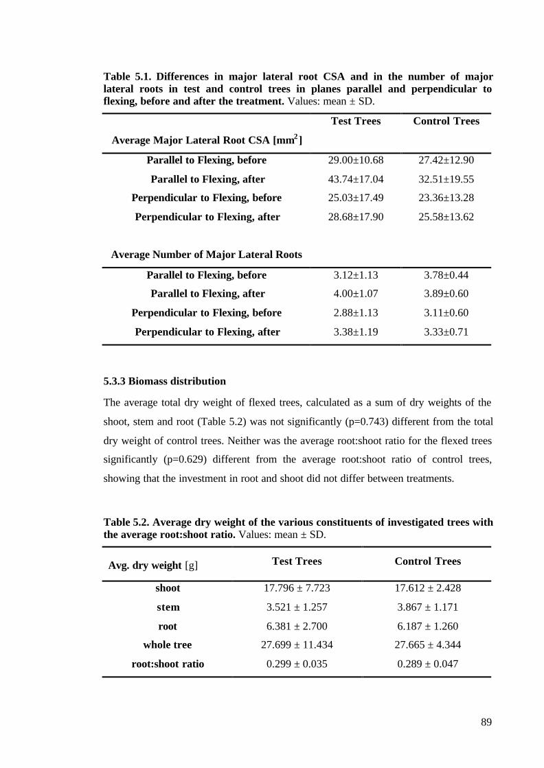
89
Table 5.1. Differences in major lateral root CSA and in the number of majorlateral roots in test and control trees in planes parallel and perpendicular toflexing, before and after the treatment. Values: mean ± SD.
Test Trees Control Trees
Average Major Lateral Root CSA [mm2]
Parallel to Flexing, before 29.00±10.68 27.42±12.90
Parallel to Flexing, after 43.74±17.04 32.51±19.55
Perpendicular to Flexing, before 25.03±17.49 23.36±13.28
Perpendicular to Flexing, after 28.68±17.90 25.58±13.62
Average Number of Major Lateral Roots
Parallel to Flexing, before 3.12±1.13 3.78±0.44
Parallel to Flexing, after 4.00±1.07 3.89±0.60
Perpendicular to Flexing, before 2.88±1.13 3.11±0.60
Perpendicular to Flexing, after 3.38±1.19 3.33±0.71
5.3.3 Biomass distribution
The average total dry weight of flexed trees, calculated as a sum of dry weights of the
shoot, stem and root (Table 5.2) was not significantly (p=0.743) different from the total
dry weight of control trees. Neither was the average root:shoot ratio for the flexed trees
significantly (p=0.629) different from the average root:shoot ratio of control trees,
showing that the investment in root and shoot did not differ between treatments.
Table 5.2. Average dry weight of the various constituents of investigated trees withthe average root:shoot ratio. Values: mean ± SD.
Avg. dry weight [g] Test Trees Control Trees
shoot 17.796 ± 7.723 17.612 ± 2.428
stem 3.521 ± 1.257 3.867 ± 1.171
root 6.381 ± 2.700 6.187 ± 1.260
whole tree 27.699 ± 11.434 27.665 ± 4.344
root:shoot ratio 0.299 ± 0.035 0.289 ± 0.047

90
5.3.4 Mechanical properties of wood
The results of the three point bending tests on the investigated trees are presented in
Table 5.3. They showed that although the stems of the flexed trees had a higher average
modulus of elasticity (E) and higher stress at yield (σmax), they were not significantly
different from the ones recorded for control trees because of the high variability.
Furthermore, the average E and σmax of the uppermost major lateral root in flexed trees
were higher but not significantly different from that of the uppermost major lateral root
in control trees. This shows that the periodical stimulation did not significantly affect
the material and structural properties of wood in either stem or root, though it might
have been significant with a bigger sample size.
Table 5.3. Average mechanical properties of stem and root wood in test andcontrol trees. Values: mean ± SD. E – modulus of elasticity, σmax – stress at yield, S –bending strength of the material. NS – statistically not significant.
Property Test trees Control Trees Difference
E stem (MPa) 354.04±175.06 289.10±53.14 NS (P= 0.277)
E root (MPa) 429.31±315.80 203.90±145.90 NS (P= 0.125)
σσmax stem (MPa) 29.553±12.312 21.890±15.092 NS (P=0.117)
σσmax root (MPa) 29.122±26.807 13.487±7.914 NS (P=0.115)
S stem (Nm) 0.746±0.223 0.702±0.109 NS (P=0.227)
S root (Nm) 0.054±0.038 0.028±0.025 NS (P=0.073)
5.4 DISCUSSION
The results of this study clearly showed that mechanical stimulation altered the
morphology and the mechanical behaviour of flexed trees compared to control trees.
The plants that survived the difficult post-replanting period showed interesting patterns
of mechanical and morphological behaviour, and revealed some of the effects that
mechanical perturbation often has on the early stages of tree growth and development.
Just as in P. contorta (Rees and Grace 1980), Sitka spruce (Stokes et al. 1995), and
some herbaceous plants (Goodman and Ennos 1996, 1998), mechanical stimulation
reduced the rate of increase in shoot height. At the tissue level, this might be attributed
to reduction in cell division and reduction in cell elongation, but the overall
thigmomorphogenic effect of the periodical unidirectional flexing resulted in a more

91
compact growth form where the shorter stems receive relatively smaller stresses
induced by the applied lateral loads than the unflexed trees.
The reduction in stem elongation goes together with an increase, often eccentric, in
radial growth of the stem (Telewski 1995) which can increase stem strength and
rigidity. However, in this investigation the radial growth of P. sylvestris was not
significantly altered by mechanical perturbation, just as in P. contorta Doug. (Rees and
Grace 1980, Phares et al. 1974), Sitka spruce and larch (Stokes et al. 1995), and several
other deciduous species (Kellog and Steucek 1977).
Unlike the stimulated P. contorta (Rees and Grace 1980), our P. sylvestris showed an
increase in the ‘apical control’ index when periodically flexed. It might be that only
periodical and short perturbations induce this change which was not apparent during the
continuous shaking of P. contorta (Rees and Grace 1980). The thigmomorphogenetic
effect of a more ‘bushy’ crown as a product of mechanical perturbation would be a
reduction in specific drag of the crown (Telewski and Jaffe 1986 on Abies fraseri), as
well as maintaining elastic or geometric similarity between the stem diameter and shoot
growth, producing a greater margin of safety against mechanical failure under lateral
loading (for review see Telewski 1995).
The increase in total root CSA, especially parallel to flexing, was similar to that found
in Sitka spruce (Stokes et al. 1995). This increase is small compared to that seen in field
studies (Fayle 1968, Wilson 1975) which is probably due to the short investigation
period and the age of the trees. It is known that various mechanical adaptations of the
root system increase its rigidity and move the hinge point away from the tree (Nicoll
and Ray 1996). Root systems of the flexed P. sylvestris trees optimised the allocation of
available assimilates for maximum strength and stability (Nicoll and Ray 1996) - in this
case a larger biomass was allocated to the roots parallel to the plane of flexing. This
resulted in a larger number of lateral roots with larger root CSA in the plane of flexing,
which in turn would increase the length of the lever arm and the tree’s resistance to
overturning (Nicoll and Ray 1996) and dissipate the experienced loads more quickly. It
is clear that the distribution of resources within the root system has altered in favour of
roots that provide most of the anchorage and which received more resources.
92
Although there was an increase in total root CSA in flexed plants, there was no
difference in root dry weights or root:shoot ratio between the flexed and the control
plants. This was similar to the findings of Goodman and Ennos (1998) on sunflower,
and Gartner on tomatoes (1994), and justified by the fact that any reduction in
root:shoot ratio might provoke instability in trees, making them more prone to
windthrow (Nicoll et al. 1995). To keep the root:shoot ratio similar to that of the
unflexed trees, the flexed ones invested in production of thicker laterals, at the same
time producing thicker stems or branches. This means that at the cellular level flexing
might have increased the average growth ring density in P. sylvestris as it did in Abies
fraseri (Telewski 1989), and P. taeda (Telewski 1990), i.e. there was an increase in
mass and volume of xylem produced per square centimetre of cambial surface area in
response to flexure (Telewski 1995).
The bending tests showed no significant difference in material properties of wood in
flexed and control trees, though the trend was for flexed plants to have stiffer and
stronger wood. Flexural stiffness (EI) is the product of modulus of elasticity (E) and the
second moment of CSA (I). The increased radial growth of the stem or root as a result
of flexing would increase the overall stiffness of the tree, making it more resistant to
bending stresses. If the flexing induced formation of compression wood with E lower
than the one in the regular wood, the compression wood would have increased the
flexibility of the tree and would have made it more resistant to lateral loads. However,
the fact that flexed stems did not have different material properties from the control
ones nor compression wood was recorded, shows that flexed stems may instead be
capable of withstanding greater loading forces than the control plants because of
changes in shape, and not material properties (Telewski and Jaffe 1986).
Since there were no significant differences in root:shoot ratio or the mechanical
properties of wood between test and control trees, the increase in the lateral resistance
recorded for flexed P. sylvestris could only be associated with the thicker stems and the
greater proportion of total root biomass allocated to the proximal major laterals, just as
in P. radiata (Watson and Tombleson 2002). This change in biomass allocation
recorded as an increase of lateral root CSA in the direction of flexing is an adaptive
mechanism in response to lateral loads previously recorded for older trees (Nicoll and
Ray 1996, Mickovski and Ennos 2002), and might be considered as an early indicator of
emerging tree stability (Watson and Tombleson 2002).
93
One of the setbacks of this study was the large percentage of die-off in test trees during
the investigation. Even with the most careful handling, it was inevitable that the root
system of the trees would be damaged during their replantation in pots. Some root tips
were probably torn off during lifting (see Sutton 1969, p. 89), or some of the longer
roots stripped, removed or drastically shorted before the trees were brought to the
Experimental Botanical Grounds. These might be some of the reasons for the large
percentage of die-off in our trees during the experiment - reasons often cited as the most
frequent and important causes of low initial survival among pines (Sutton 1969. p. 89).
Results of this study might be useful in forestry practices. It might be possible to reduce
wind damage by selecting trees with root systems that respond faster to lateral loads and
provide better anchorage (Nicoll et al. 1995). Selecting trees that develop a higher
root:shoot ratio and more even biomass distribution between the thicker major lateral
roots might reduce the loss of the trees to windthrows. It is known that trees respond
differently to intermittent and continuous winds (Telewski 1995), but it is not known
how much flexing-induced changes in the growth of the trees alter their resistance to
windthrow. More detailed research is needed on young trees growing in the field,
investigating the immediate responses and adaptations of their root systems to
mechanical perturbation.

94
CHAPTER SIX: A MORPHOLOGICAL AND MECHANICAL
STUDY OF THE ROOT SYSTEMS OF SUPPRESSED CROWN
SCOTS PINE PINUS SYLVESTRIS
6.1 INTRODUCTION
In situ investigations on root systems have a long history despite all the difficulties of
measuring roots covered by layers of soil. In the last twenty years major steps forward
have been made in this field of investigation starting with the introduction of new
methods for studying the distribution and function of roots in the soil, as a supplement
to the old method of visual inspection. These methods include separation of intact root
systems from soil, separation of roots from soil cores or observation of root distribution
down the soil profile, and tracer methods for root location (see reviews in Root
methods: a handbook, edited by Smit et al. 2000).
Recent years have also brought new methods to study the root anchorage of trees
(Coutts 1983, 1986; Mattheck et al. 1995, Crook and Ennos 1996, Stokes et al. 1997,
Nicoll and Armstrong 1998, and Goodman and Ennos 1999). An improved
understanding of this, one of the two main functions of roots (Coutts 1987), is still
required in forestry and arboriculture. A more advanced knowledge of the root
morphology and architecture of as many species as possible may also provide further
insight into the way in which the form is related to the function in root systems (see
Ennos 2000).
Symmetry in the root systems of shallowly rooted individual trees may have significant
impact on their overall stability (Coutts et al. 1998). The aspects of root symmetry
include the growth and origin of primary roots and root initiation (Coutts et al. 1998),
both of them poorly investigated and understood. Tree stability is also reduced in trees
in which structural roots are missing or poorly developed on one side (Coutts 1983).
Previous investigations on this subject carried out on Pinus radiata (Somerville 1979)
in New Zealand showed a root distribution very close to symmetrical, and introduced a
new winching method for carrying out this kind of study. However, more recent

95
investigations on Sitka spruce have shown that their root systems are often asymmetric,
developing less in the direction of the plough furrows (Coutts et al. 1990), or just
unevenly (Nicoll et al. 1995).
The development of primary roots is influenced by many external factors.
Environmental factors that might affect tree stability and anchorage include not only
water and nutrient relations, but also the more physical aspect of the soil shear strength
which can cause soil impedance that can inhibit root growth (Taylor and Gardner 1963)
on one hand, but also provide anchoring stability on the other. Roots are said to exert a
maximum radial pressure of around 800 kPa (McLeod and Cram 1996), a value that was
not expected to be reached in this study. The depth of the root origin related to the
distribution of mass (or the cross sectional area - CSA) could also show whether
environmental factors such as assimilate supply are the primary factors in the vertical
distribution of root mass. The secondary growth of roots can also be affected by their
environment, both nutritional and physical. For instance it is well established that
buttress root formation is stimulated in trees parallel to the prevailing wind direction
(Nicoll and Ray 1996), particularly on the leeward side.
Bearing in mind that a large proportion of the work on tree anchorage and root system
asymmetry has been carried out on Sitka spruce, mostly because of the problems with
the windthrow this species is experiencing in the UK, one of the aims of this study was
to provide information on another important forestry species Pinus sylvestris. The study
used modern techniques to investigate the anchorage strength and distribution of
anchorage rigidity around the trees and attempted to relate these to the horizontal and
vertical distribution of roots. By these means it was hoped to gain information about the
mechanics of anchorage in this species, and of the factors that determine root
distribution and development.

96
6.2 MATERIALS AND METHODS
6.2.1 Site Details
Twenty-two 23-year-old suppressed crown Pinus sylvestris trees were randomly
selected from a 30 m x 20 m tree stand in the University of Manchester Granada
Arboretum in Jodrell Bank, Cheshire (grid ref. SJ 794716). The trees had been planted
at 1.8 to 2.0 m spacing in clay loam soil in a rectangular grid oriented in a north-south
and east-west orientation. The selection included as many trees as we were allowed to
use from the outside tree belt (more exposed to the wind and external factors), while the
majority of the sample consisted of trees grown inside the tree stand. The trees tested in
this study had average diameter at breast height (DBH) of 14.1±2.2 cm (in this chapter,
mean ± SD). The trees on the outer belt of the stand had an average DBH of 14.7±2.1
cm, that was not significantly (p=0.425) higher than the average DBH of inner trees
13.8±2.3 cm. No thinning of this particular stand had been done in recent years.
Prevailing winds on this site come from the South West.
6.2.2 Selection and Extraction of the Study Trees
In early 2000, 22 trees were marked as a part of the study sample. Seven trees from the
outer belt of the stand were selected together with 15 from the inner part. During the
fieldwork in March, April, and May 2000, each tree was cut on average 1.70 m above
the ground, and the upper part of the stem, together with the tree crown was carefully
transported outside the tree stand.
6.2.3 Preliminary Tests
In order to get an idea of the root morphology and methods of anchorage for the
suppressed crown trees, preliminary tests were carried out on two test trees. Two
suppressed crown trees with DBH 10.5 cm and 12.7 cm from the inside of the stand
were studied using the technique developed by Coutts (1983) and Crook and Ennos
(1996). The litter around the tree trunk was cleared and the orientation and location of
the main lateral roots was noted. A trench parallel to the direction in which the tree was
going to be pulled over was dug up. The trench was 60cm deep and 50 cm wide, and it
extended approximately 80cm from each side of the trunk. Lateral roots growing out
from the trunk on the side of the trench were cut away with an axe. The tree was then
winched over at about 15° min-1 and movements of the soil and roots were noted. The
centre of rotation of the root system was also noted, as well as the sounds of root

97
breakage. After the tree had toppled, the root system was cleared from the soil and
examined closely to find broken roots and other signs of mechanical failure. Visual
observations showed that the outward spreading roots of the outer belt tree were longer
and thicker than the roots of the inner tree. To ensure that the failure occurred in the
anchorage system rather than in the trunk wood, the experiments were carried out in
early March 2000, when the soil was still moist.
6.2.4 Overturning Tests
To investigate the degree of symmetry in anchorage rigidity and also the overall
anchorage strength, a method shown in Figure 6.1 was developed to sequentially pull
each tree in four directions, all oriented approximately 90° from each other around the
tree trunk. A further twenty trees ranging in DBH from 8.91 cm to 17.19 cm were
pulled over from March 16, 2000 to May 19, 2000 in this way. The crown of the trees,
together with the upper part of the stem, was cut off and the lower part of the stem, that
varied in height from 1.70 m to 2.04 m, was left. The trees were prepared for the
experiment by removing the needle litter from around the trunk, and the lateral root
system was revealed by careful removal of the few uppermost centimetres of soil.
Preliminary tests were carried out by hand to determine the direction in which the
anchorage seemed most rigid. One end of a winch (TIRFOR, T532) was connected via a
force transducer (Defiant Weighing Ltd., Kent, England) and via a sling to the tree that
was about to be pulled down at a height that ranged from 1.70 to1.80 m. The other end
of the winch was secured to the base of another tree in the stand using another sling.
The force transducer, which was capable of measuring forces up to 20 kN, sent its
output to a portable battery-powered data logger with a live display which showed a
graph of force against time on a laptop computer using PICOLOG (Pico Technology
Ltd., UK) software. As shown in Figure 6.1 the winch was then used for the real tests,
in which the trees were pulled first at 90°, then at 180°, 270°, and finally towards the
most rigid direction. The last pull that determined the anchorage strength was therefore
from the side where the maximum overturning resistance was expected.

98
Figure 6.1 a) Top view and b) side view of the winching apparatus and method
used in this study.
99
The trees in this experiment were pulled at a constant rate of one winch cycle,
approximately 2 cm, per 4 seconds. The tree was winched in the first three directions
only up to a displacement of 14 cm at the top of the stem, and the slopes of the
increasing pulling force versus stem displacement graphs were calculated for every
pulling direction for each tree. While pulling from the fourth side, winching was
continued until the maximum resistance of the tree was mobilised and the tree failed.
The test was terminated once the force registered on the display started to decline from
its maximum. The maximum overturning moment was calculated for every tree by
multiplying the maximum recorded pulling force by the height of pull up. Again, special
attention was paid to the root and soil movements as well as to the sounds of breakage.
The anchorage asymmetry ratio was defined as the ratio between the mean slopes of
the pulls in the direction of the final pull and the mean slopes in the direction
perpendicular to it.
6.2.5 Root System Morphology and Architecture Measurements
To allow the root system to be examined and the distribution of cross sectional area
(CSA) around the trunk to be measured, the trees were excavated or winched over
completely and soil was cleared from the upper root system. The root system
components were then measured with a technique similar to that described by Nicoll
and Ray (1996). Each structural root, defined as a root with diameter greater than 2.0
cm at a distance of 20 cm from the tree trunk, was investigated. The number of laterals
was recorded, together with their horizontal and vertical diameters, dh and dv
respectively, at the point 20 cm from the trunk measured with callipers. These were
used to calculate the CSA of each root using the equation CSA=(πdhdv)/4. The
orientation of the laterals was also measured using a compass, as well as the depth of
their origin.
6.2.6 Soil Measurements
Soil shear strength was measured around every tree with a dial torque wrench (RS 575-
633) on which a 19mm shear vane was attached. The vane was pressed vertically into
the soil, and the ratchet of the wrench was then slowly rotated clockwise until the soil
failed in shear. The maximum shear force was recorded on the dial of the wrench. The
shear strength of the soil was measured at three depths (5 cm, 10 cm, and 15 cm) in
every one of the four pulling directions for every tree.

100
6.2.7 Investigation of Root Distribution Relative to the Overturning Direction
Roots were classified into four separate direction classes, depending on whether they
were in the quadrants facing towards or away from the final pull, or in the two
quadrants at right angles. The root asymmetry ratio was defined as the fraction of the
CSA activated in the direction parallel to the final pull divided by the CSA activated in
direction perpendicular to it. The root asymmetry ratio was then plotted against the
anchorage asymmetry ratio and subjected to correlation analysis to determine whether
root system asymmetry and anchorage symmetry were related.
6.2.8 Investigation of Absolute Root Distribution
The centre of the root cross-sectional area was calculated for each tree in order to
investigate the distribution and asymmetry of the biomass in the tree. This was carried
out as described in Nicoll and Ray (1996), giving the greatest weight to the largest roots
that might have the greatest role in the tree stability. The center of the CSA of a root
system is the average position of structural roots relative to the center of the stem, using
measured azimuth angles and weighted by their CSA.
The origin of the coordinate system is the center of the trunk and if the center of the
CSA is also there it would indicate an even distribution of the root mass around the tree.
In that aspect, the center of the CSA of the root system of a tree has coordinates:
X=ΣXi ; Y=ΣYi (eqn 6.1)
where the Cartesian coordinates of the ith root weighted by the CSA are:
Xi=Disinθ ; Yi=Dicosθ (eqn 6.2)
where θ is the azimuth angle and
Di=∑ i
i
dd
, (eqn 6.3)
where di=dvdh is the product of the horizontal and vertical diameters of the ith root. The
distance between the center of the root CSA and the origin of the coordinate system is :
R=(X2+Y2)1/2, (eqn 6.4)
while its orientation is: θ=tan-1(X/Y).
Large values of R indicate that roots tend to cluster together in a preferred direction θ,
whereas small values imply uniformity around the tree trunk (Mardia 1972). S0= 1- R is
the common variance of the independent variables Xi and Yi, and the hypothesis of no

101
clustering can be tested using the test statistic nR2/S0. Under the hypothesis of no
clustering, this statistic has an F-distribution with 2, 2(n-1) degrees of freedom, and the
hypothesis is rejected whenever nR2/S0 is greater than F(2, 2(n-1), α) when testing at
the α% significance level (Nicoll et al. 1995).
6.2.9 Investigation of Root Distribution Relative to Depth
The underground part of the root system was divided into four depth horizons: 0 cm to 5
cm, 5 cm to 10 cm, 10 cm to 15 cm, and deeper than 15 cm; all of the major roots were
categorised in one of the horizons according to the depth of their origin. The location of
sinkers and eventual taproots was also noted and a sketch of the root system was
produced for each tree.
6.2.10 Statistical Methods
All the data were put in the SPSS computer package, and several statistic methods, such
as one- and two-way ANOVA, regression and correlation, were used to compute the
parameters presented in this study.
ANCOVA and the multiple regression tests were also carried out in a DOS application
written by Dr Robert Callow, University of Manchester.
6.3 RESULTS
6.3.1 Preliminary Tests
The trenching method revealed that both of the test trees had complex root systems,
with strong horizontal lateral roots distributed around the stem. Several sinker roots
were recorded originating from some of the laterals, with strongly geotropic
characteristics. Furthermore, there were several sinkers originating directly from the tree
base on one of the trees, while the other one had a deep tap root. It is important to note
that the tap root of the second tree as well as the sinkers of the other had a specific form
and orientation. They were similar in cross section to the ‘I’ shaped beams known in
engineering, and also recorded in some previous studies (Mattheck et al. 1995, Stokes et
al. 1997), with the long axis orientated along the lateral from which they has emerged.

102
Despite the differences in root morphology, both trees failed in a similar way as they
were pulled over. Soil failure occurred first close under the stem, and cracks in the soil
then spread towards the edges of the root-soil plate as the winching continued. There
was significant movement in the roots, accompanied by the development of a complex
network of cracks in the soil on the windward side and loud noise of root snapping after
the trunk had been displaced by cca. 20° from the vertical. Both trees rotated about a
point just below the tree base, just on leeward side, and the leeward laterals were pushed
into the soil while the tap root was bent and pulled up a bit. Consequently, as the test
proceeded, windward laterals came out on the windward side after originally being
confined by the surrounding soil. The tap root of one of the test trees snapped when the
trunk had been displaced cca. 45° from the vertical.
6.3.2 Anchorage Rigidity
The overturning force rose with the displacement of the stem from the vertical. The
rigidity of the anchorage of the 20 trees ranged from 0.484 kNm deg-1 to 3.372 kNm
deg-1 (Table 6.1). 1-way ANOVA showed that the mean slope was significantly
(F1,19=25.254, p<0.001) greater for the trees from the outer belt of the stand, showing
their greater resistance to overturning. However, there was no significant difference
between the rigidity of the trees that failed in their roots and those ones that failed in
their stems.
Table 6.1 The mean anchorage rigidity and the percentage of the root crosssectional area mobilised in tension during each pull of the overturning tests.Values: mean ± SE.
90° 180° 270°Parallel to the
most rigiddirection
MeanAnchorage
Rigidity[kNm deg-1]
0.565±0.317 0.789±0.586 0.643±0.335 2.024±0.969
Root CSA[%] 22.2 ± 1.63 15.9 ± 2.31 23.8 ± 2.71 38.1 ± 3.28

103
It is worth noting that the slope of the fourth and final pull was significantly
(F1,79=5.980, p=0.025) higher than the other pulls for every tree investigated. This was
always followed by the slope of the second pull, in which the tree was pulled in the
opposite direction from the final pull. Furthermore, the final pull for the outer belt trees
was always from the inside of the stem, i.e. the most rigid direction is the one facing the
outside of the stand. These results justified the chosen direction of pulling as the
strongest and most resistant.
6.3.3 Overturning Tests
As overturning proceeded, the overturning moment initially increased, reached its
maximum and plateaued, before falling again. A similar pattern was recorded in the
shape of the overturning force vs. time graph for both inner and outer belt trees.
Overturning moments ranged from 2.96 kNm at an angle of 14.57° to 15.69 kNm at an
angle of 24.85°, or 9.10±3.640 kNm on average at an angle of 23.4° for the whole
population. The average overturning moment for the outer trees was 11.1±3.6 kNm,
which was not significantly (F1,19=2.839, p=0.109) higher than the average overturning
moment for the inner trees: 8.24±3.4 kNm.
The overturning moment increased with the increase of DBH for the trees studied. The
regression lines from the LogDBH vs. Log M graph show that the overturning moment
increases approximately with the second power (not significantly different from 2) of
the DBH for these trees: logM = 2.0668 logDBH - 1.4454 (r2 = 0.571) (Figure 6.2).
ANCOVA showed that the slopes of the overturning moment with the DBH for the
inner and the outer trees in the stand are not significantly different (F1,19=1.609).
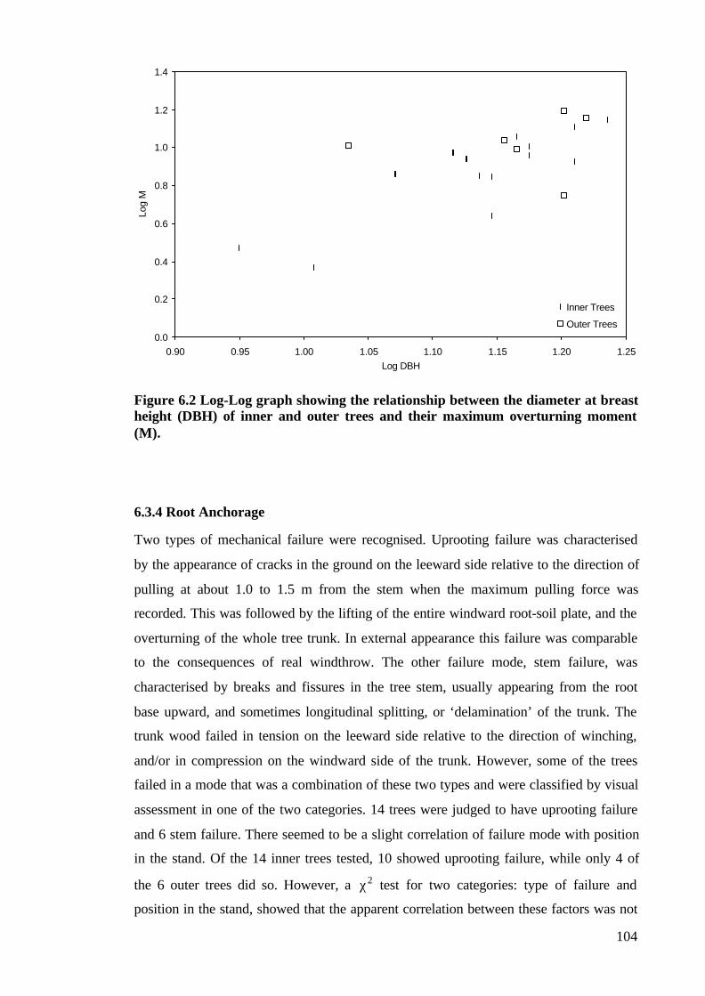
104
Figure 6.2 Log-Log graph showing the relationship between the diameter at breastheight (DBH) of inner and outer trees and their maximum overturning moment(M).
6.3.4 Root Anchorage
Two types of mechanical failure were recognised. Uprooting failure was characterised
by the appearance of cracks in the ground on the leeward side relative to the direction of
pulling at about 1.0 to 1.5 m from the stem when the maximum pulling force was
recorded. This was followed by the lifting of the entire windward root-soil plate, and the
overturning of the whole tree trunk. In external appearance this failure was comparable
to the consequences of real windthrow. The other failure mode, stem failure, was
characterised by breaks and fissures in the tree stem, usually appearing from the root
base upward, and sometimes longitudinal splitting, or ‘delamination’ of the trunk. The
trunk wood failed in tension on the leeward side relative to the direction of winching,
and/or in compression on the windward side of the trunk. However, some of the trees
failed in a mode that was a combination of these two types and were classified by visual
assessment in one of the two categories. 14 trees were judged to have uprooting failure
and 6 stem failure. There seemed to be a slight correlation of failure mode with position
in the stand. Of the 14 inner trees tested, 10 showed uprooting failure, while only 4 of
the 6 outer trees did so. However, a χ2 test for two categories: type of failure and
position in the stand, showed that the apparent correlation between these factors was not
0.0
0.2
0.4
0.6
0.8
1.0
1.2
1.4
0.90 0.95 1.00 1.05 1.10 1.15 1.20 1.25
Log DBH
Log
M
Inner Trees
Outer Trees

105
significant, so that the position of the tree in the stand did not significantly affect the
mode in which it failed under critical loads.
6.3.5 Root System Architecture
The total cross sectional area (CSA) of major roots varied from 42 to 337 cm2, or
127±65 cm2 on average for the population. The trees from inside the stand had mean
CSA of 109±47 cm2, which was significantly (F1,19=4.423, p=0.05) lower than the
average CSA of the outer trees: 171±85 cm2. The vertical distribution of the CSA,
presented on Figure 6.3, showed that 48±2.23% of it was distributed between 0 and 5
cm depth, 32±1.87% between 5 and 10 cm depth, 17±2.91% between 10 and 15 cm
depth, and 3±0.49% lower than 15 cm. Only 5 of the 20 trees had major roots deeper
than 15cm, and 5 had all their major roots in the first 10cm depth.
Figure 6.3 Graph showing the relationship between the diameter at breast height(DBH) of inner and outer trees in the stand and their root cross sectional area(CSA).
The percentage of the root CSA mobilised in tension during the overturning tests (the
four different pulls: 180°, 90°, 270°, and parallel to the greatest rigidity) is shown in the
Table 5.1, assuming that the CSA mobilised in tension is the one in the quadrant
opposite from the direction of pulling.
Regression analysis showed that the trees with larger DBH have major roots with larger
CSA (LogCSA = 1.786 LogDBH + 0.0193, r2 = 0.640). It can be seen on Figure 6.3 that
1.6
1.7
1.8
1.9
2.0
2.1
2.2
2.3
2.4
2.5
2.6
0.95 1.00 1.05 1.10 1.15 1.20 1.25
Log DBH
Log
CS
A
Inner Trees
Outer Trees

106
this is true both for the inner trees (Log CSA= 1.6154 Log DBH + 0.1693, r2 = 0.460),
and the outer trees (Log CSA = 1.6064 Log DBH + 0.3297, r2 = 0.380). Visual
observation also suggested that the inner trees had more sinker roots and tap roots,
though this observation was not quantified.
Multi-factorial (two factor) regression analysis showed that together root CSA and the
trunk DBH had a significant (p<0.05, r2=0.518) effect on the overturning moment,
though CSA itself had a non-significant (p=0.318) effect on the resistance of the whole
tree.
The centre of root CSA calculated with the statistical method explained in the methods
section, showed significant (p<0.05) clustering of root direction in 7 out of the 20 trees
studied. Relatively more were outer trees (4 out of 6) than inner trees (3 out of 14).
However there was no apparent correlation with failure mode, as they included 5 of the
14 trees that had uprooted and 2 of the 6 trees that had stem failure. For all 20 trees
together as shown in Figure 6.4, the mean centre of the root CSA pointed toward 150°
from north with a mean R-value of 0.384 which indicates significant (p<0.05)
asymmetry.

107
Figure 6.4 Polar plot of the mean centres of the root cross sectional area of eachtree. Orientation of the major roots is given in degrees (o) of azimuth angle, and 0indicates North. The R value (non-dimensional) is plotted as the distance from thecentre of the plot.
There was no significant correlation between root asymmetry ratio and the anchorage
asymmetry ratio (R= -0.211, p=0.372), as shown on Figure 6.5. Therefore asymmetry in
the lateral root system did not appear to cause the asymmetry in the anchorage rigidity.
Polar Plot
0.0 0.1 0.2 0.3 0.4 0.5 0.6 0.70.0
0.1
0.2
0.3
0.4
0.5
0.6
0.7
0.00.10.20.30.40.50.60.70.0
0.1
0.2
0.3
0.4
0.5
0.6
0.7
0
30
60
90
120
150
180
210
240
270
300
330
Col 1 vs Col 2

108
Figure 6.5 Graph showing the relationship between the asymmetry in thedistribution of major lateral root CSA (root asymmetry ratio) and the asymmetryin the overturning resistance (anchorage asymmetry ratio) around the tree trunk.
6.3.6 Soil Conditions
Soil shear strength as a marker of soil resistance to root expansion was not significantly
(p=0.352) different for the inner and outer trees. However, the soil shear strength
increased with depth, and it was on average 49±3 kNm-2 at 5 cm depth, 81±5 kNm-2 at
10 cm depth, and 109 ±7 kNm-2 at 15 cm depth. Though more root area is found in the
highest (and therefore, the weakest) soil horizon, regression (Figure 6.6) showed that
within each horizon, the root CSA actually increased with increasing soil strength (0-5
cm depth: CSA = 41.134Shear Strength - 4.0878, r2 = 0.184; 5-10 cm depth: CSA =
16.106Shear Strength + 8.874, r2 = 0.056; 10-15 cm depth: CSA = 4.901Shear Strength
+ 8.6192, r2 = 0.012).
0
1
2
3
4
5
6
0 2 4 6 8 10 12 14 16
Root Asymmetry Ratio
Anc
hora
ge A
sym
met
ry R
atio

109
Figure 6.6 Graph showing the relationship between the root cross sectional area(CSA) and the soil shear strength in the three different soil horizons: 0-5cm, 5-10cm, and 10-15cm.
6.4 DISCUSSION
The methods developed for this study worked well and showed that there was extensive
anchorage asymmetry in suppressed crown trees, unlike in Somerville’s (1979) Pinus
radiata. The results also seem to suggest three other things: first, that lateral roots are
not the major source of anchorage in our Pinus sylvestris trees; second, that root system
asymmetry is also common in this species; and third, that trees growing on the inside
and outside of the stand show many differences in morphology and mechanical
behaviour.
The first piece of evidence that lateral roots do not provide much anchorage, is the data
obtained for the anchorage strength of the investigated trees. The statistical analysis
showed that the resistance of the tree to overturning is proportional to the second power
of the DBH of the tree. This is much lower than the expected exponent of 3 predicted
for an isometrically growing tree with lateral roots (Ennos 1993), but a similar exponent
to that found by Crook and Ennos (1997) on the tropical rainforest species Mallotus
wrayi which is anchored mainly with a tap root. Second, though root CSA increases
0
20
40
60
80
100
120
0.5 1.0 1.5 2.0 2.5 3.0 3.5
Shear Strength [N]
CS
A [c
m2]
0-5cm depth
5-10cm depth
10-15cm depth
110
with trunk diameter as expected, multiple regression shows that overturning resistance
is significantly affected only by trunk diameter and not by root CSA. Finally, though on
average higher root CSA is found in the quadrants parallel to the direction of maximum
rigidity than in the perpendicular quadrants, there was no significant correlation
between the root asymmetry ratio and the anchorage asymmetry ratio.
All of these results, together with the visual observations of the preliminary tests,
suggest that it is not the lateral roots but the sinker and tap roots that provide the vast
majority of anchorage. These can resist overturning by two mechanisms: the resistance
of windward sinkers and tap roots to uprooting, as in the larch studied by Crook and
Ennos (1996); and the resistance of these roots to bending as in the tap rooted Mallotus
(Crook et al. 1997). Significantly in this regard, in most of the trees the long axis of the
‘I’ shape of the tap root seemed to be aligned more-or-less parallel to the orientation of
the maximum overturning moment and would have the greatest bending resistance in
this plane.
In this study, there was a preferred general orientation of the tree roots in several trees,
and the overall centre of root CSA had a magnitude that also suggested significant
asymmetry of the entire stand. Furthermore, the magnitude of the centre of CSA,
R=0.384, suggests that roots with similar diameters are arranged approximately evenly
around the stem in three directions, while the fourth direction is either lacking roots, or
has roots with considerably smaller diameters. This kind of root distribution was, in
fact, recorded for 6 of the investigated 20 trees. Our examination showed that there was
quite a degree of asymmetry of the cross sectional area (CSA) of lateral roots around the
trunk of our suppressed crown trees. Asymmetry, as suggested by Coutts et al. (1998),
can be of more than one type. Ideally, in type I asymmetry the roots are arranged
symmetrically about the trunk, but have varying diameters which give an asymmetrical
structure. In type II asymmetry, in contrast, the roots themselves are arranged
asymmetrically around the stem, although they might be uniform in diameter. Bearing
in mind the overall morphology of the root systems of the studied trees, it is supposed
that the asymmetry in this case tends to be more of the type II, having roots with more
or less uniform diameter, but arranged asymmetrically around the stem.
What causes the root asymmetry, then? Unlike the study of Coutts et al. (1990) study it
was not due to soil relief, as the ground was flat. Neither was it due to root impedance
111
as the root area was actually higher in stronger soil in each of the horizons (Figure 6.6).
This is exactly the opposite of what might be expected if soil had impeded root growth,
but the soil compactness and shear resistance in this study were much lower than those
which limited lateral root growth in the studies of Bengough et al. (1997), and Misra
(1997). One possible alternative would be thigmomorphogenic effects, which might be
expected to stimulate secondary root growth in the plane of the prevailing wind. This
seems unlikely as the overall centre of root CSA was oriented towards the South East
(150° from North), virtually at right angles to the prevailing South West wind. Instead,
the evidence points to root competition as being a major cause. A greater proportion of
the outer trees, which would have asymmetric root competition, had more asymmetric
root systems than the inner trees. Moreover, visual observations suggested that the
outward spreading roots of the outer trees were longer and thicker than the roots of the
inner trees. It is also pertinent that the orientation of roots of the investigated plants was
modified by their proximity to those of adjacent trees. In isolation, or in the outer belt,
they grew horizontally (Coutts 1996) while surrounded by other plants they tend to turn
downwards, or even more to split into a group of shorter and thinner laterals (Plate 6.1).

112
Plate 6.1 The root system of an average 18-year-old P. sylvestris tree from insidethe tree stand at the University of Manchester Granada Arboretum in JodrellBank, Cheshire. The horizontal lateral roots of inner trees tend to grow thinner andshorter, their growth probably obstructed by the one of the roots of adjacent trees.
113
It is known that the chances of becoming a major root are greater for roots with a large
diameter of primary xylem (Russell 1977). It is the same for roots whose origin is
closest to the surface and to the assimilates located there. The results on the depth of
origin of the major roots in this study do show that there is a strong tendency for most
laterals to develop from the upper part, near the trunk base. This could be because of the
higher nutrient levels in upper soil layers, but as soil shear strength increased with the
depth, it is possible that mechanical impedance of the soil could be one major obstacle
to root expansion or lateral root development in lower soil horizons.
Many of the differences between inner and outer trees were just those that might be
expected. The inner trees had thinner trunks, lower root CSA and had correspondingly
lower overturning moments. In addition the greater degree of asymmetry in the root
systems of the outer trees would be predicted due to root competition. There was also a
slight, but non-significant trend for outer trees to fail more in their stems while their root
system did not show visible signs of failure, and for inner trees to fail more in their root
system. It is conceivable that such a difference in anchorage mechanisms of suppressed
crown trees could be due to thigmomorphogenetic effects on roots resulting in outer
layer trees producing relatively stronger root systems so that they broke more in their
stems, while the inner trees were windthrown. However, it might result indirectly from
the enhanced root growth due to lower root competition in the outer trees. One possible
explanation of the large numbers of wind-blown trees recorded in some studies
(Somerville 1979) is that the wind loading was strong enough to overcome the bending
resistance of the outer belt trees. They failed in their stems, which left the inner trees
exposed to loads they are not used to receive, so they fail in their anchorage and topple.
114
CHAPTER SEVEN: ANCHORAGE MECHANICS AND
ASYMMETRY IN THE ROOT SYSTEM OF MACEDONIAN PINE
PINUS PEUCE (GRIS.)
7.1 INTRODUCTION
Recent years have brought new methods of investigation of root systems which
supplement the old method of visual inspection (see reviews in Root methods: a
handbook, edited by Smit et al. 2000). Despite all the difficulties of measuring roots
covered by layers of soil, a step forward was made with introduction of more efficient
methods for exploring the distribution and function of roots in the soil in connection to a
tree’s anchorage (Coutts 1983, 1986; Mattheck et al. 1995, Crook and Ennos 1996,
Crook and Ennos 1997, Stokes et al. 1997, Nicoll and Armstrong 1998, and Goodman
and Ennos 1999). Acknowledging that anchorage is one of the two main functions of the
root system (Coutts 1987), it was suggested (see Ennos 2000) that a more advanced
knowledge of the root morphology and architecture of as many species as possible
might provide further insight into the way in which the form is related to the function in
root systems.
Root system asymmetry increases along with the variability of the root system as trees
age (Sutton 1969) as a result of the variety of stimuli the tree experiences, and this
might significantly reduce the overall stability of a tree (Coutts et al. 1998). Tree
stability is also reduced in trees in which structural roots are poorly developed or even
missing on one side (Coutts 1983). Previous studies on root symmetry have produced
variable results; Somerville (1979) investigating the root system of Pinus radiata in
New Zealand, showed that the root distribution was very close to symmetrical, whereas
more recent studies on Sitka spruce have shown that their root systems are often
asymmetric, developing less in the direction of the plough furrows (Coutts et al. 1990),
or just unevenly (Nicoll et al. 1995). The investigation of Mickovski and Ennos (2002)
on Pinus sylvestris also showed that there is a preferred orientation and clustering of
roots in many suppressed crown trees.

115
Root asymmetry can result from the asymmetric origin and growth of primary roots
(Coutts et al. 1998). This in turn can be affected by a number of external factors,
including environmental factors such as water and nutrient supply (Mickovski and
Ennos 2002), and physical factors such as high soil shear strength which can impede
root growth (Taylor and Gardner 1963), but also provide better anchorage for the tree.
The environment also affects the secondary growth of roots. It is known that buttress
root formation is stimulated in trees parallel to the prevailing wind direction (Nicoll and
Ray 1996), particularly on the leeward side, and that the shape of the roots becomes
more oval in weaker soils, in some instances even resembling the ‘I’ beams common in
engineering (Nicoll and Ray 1996).
Trees also differ in their relative rooting depths, both between species and with growth
conditions, and this in turn affects the tree stability. Soil compaction, or even
waterlogging (Coutts 1983, 1986), might restrict deeper rooting of trees, which will
restrict the stability of the tree. Root systems of trees grown in such conditions often
have larger lateral spread with stronger laterals which help the tree from toppling under
external loads.
Nutrient supply can also have an effect on the rooting depth and the vertical distribution
of the root biomass of a tree. Considering the fact that assimilates are more readily
available closer to the surface of the soil, trees usually have a large portion of their
major lateral roots in the uppermost layers of the soil (Sutton 1969, Somerville 1979,
Stokes and Guitard 1997). This kind of vertical distribution may also decrease the
stability of the tree. It is also possible that the lateral roots in the uppermost soil
horizons use the major portion of the nutrients available near the soil surface and thus
occlude the growth of the deeper roots, sinkers and the tap roots (Sutton 1969, Wilson
1975)
In spite of their frequent designation as deep-rooted, windfirm species, pines can be
very susceptible to windthrow on sites that restrict rooting (Sutton 1969). Problems with
windthrow in the UK have focused the vast majority of the research on the anchorage of
Sitka spruce as the most widespread plantation conifer. One of the aims of this study is
to extend knowledge to another forestry species: Macedonian pine (Pinus peuce Gris.),
endemic to the Balkans, and grown in completely different environmental conditions
from those prevailing in the UK (Popnikola 1959, Pejoski and Todorovski 1959).

116
In order to reveal the anchorage mechanics of this species, modern techniques were
used in this study to investigate the anchorage strength of mature trees and relate it to
the size of the tree and the root cross sectional area (CSA). The asymmetry of the
overall root system as well as the vertical distribution of root biomass was also
explored, especially in relation to possible thigmomorphogenetic effects and
competition for nutrients. An attempt was made to relate the root asymmetry to the
asymmetry in anchorage rigidity, and to relate the overall root morphology to the
primary functions of the root system. By comparing these findings to these on other
species, particularly to the related Pinus sylvestris, it was hoped to gain knowledge on
the factors that determine root development and the root biomass distribution both in
depth and around the tree.
7.2 MATERIALS AND METHODS
7.2.1 Site Details
Twenty-two 19 to 23-year-old suppressed crown Pinus peuce trees were randomly
selected from a 50 m x 100 m naturally regenerated tree stand in the Pelister National
Park near Bitola, Macedonia, with the longer side of the site oriented in north-south
direction. The trees were grown on a brown clay soil and the spacing between the trees
varied from 1.5 to 1.9 m. The selection included as many trees as we were allowed to
use from the outside tree belt (more exposed to the wind and external factors), while the
majority of the sample consisted of trees grown inside the tree stand.
Pinus peuce trees tested in this study had average diameter at breast height (DBH) of
11.77±1.255 cm (in this chapter, mean ± SD). The trees on the outer belt of the stand
had average DBH of 11.75±0.81 cm, but this was not significantly (p>0.05) higher than
the average DBH of inner trees 11.83±1.43 cm. No thinning of this particular stand had
been done in recent years. Prevailing winds on this site come from the South East.
7.2.2 Selection and Extraction of the Study Trees
In the spring of 2001, 22 trees were marked as a part of the study sample. Seven trees
from the outer belt of the stand were selected together with 15 from the inner part.
117
During the investigations in May 2001, each tree was cut on average 1.75 m above the
ground, and the upper part of the tree, together with the tree crown was carefully
transported outside the tree stand.
7.2.3 Preliminary Tests
In order to get an idea of the root morphology and methods of anchorage for the
suppressed crown trees, preliminary tests were carried out on two test trees: one from
outer belt of the stand and one from the inside of the stand, with DBH of 12.3 cm and
11.9 cm respectively. They were prepared and tested using the technique developed by
Coutts (1983) and Crook and Ennos (1996), and described in Chapter Six of this thesis.
Visual observations showed that the outward spreading roots of the outer belt tree were
longer and thicker than the roots of the inner tree. To ensure that the failure occurred in
the anchorage system rather than in the trunk wood, the experiments were carried out in
March 2001, when the soil was still moist.
7.2.4 Overturning Tests
To investigate the degree of symmetry in anchorage rigidity and also the overall
anchorage strength, the winching method and equipment described in Chapter Six of
this thesis was used to sequentially pull each tree in four directions, all oriented
approximately 90° from each other around the tree trunk. A further twenty trees ranging
in DBH from 8.60 cm to 14.32 cm were pulled over during May, 2001 and their
anchorage strength was recorded together with the anchorage asymmetry ratio which
was defined as the ratio between the mean slopes of the pulls parallel to the final pull,
and the mean slopes in the direction perpendicular to it.
7.2.5 Root System Morphology and Architecture Measurements
The measurements of the root system architecture and morphology of the investigated
Pinus peuce trees were carried out in the same way as for the Pinus sylvestris trees in
Chapter Six of this thesis.

118
7.2.6 Soil Measurements
Soil resistance to penetration was measured around every tree with a Proctor field
penetrometer (Wille Geotehnik, Germany). It consisted of a special spring
dynamometer with a calibrated scale on the stem of the handle, where a sliding ring
indicated the maximum applied load. A special needle with an area of 19.63 cm2 was
mounted on the measuring end of the penetrometer.
The soil was cleaned from the litter and the surface from which the reading was taken
was flat, so the needle could adhere better to the soil. The penetrometer was held in a
vertical position and pressure was applied at the same time controlling the rate of
penetration by steadying the arms against the front of the legs. The usual rate of
penetration was around 13 mm sec-1 for a depth of no less than 76 mm. Three tests in
each soil horizon (5 cm, 10 cm, and 15 cm) were carried out in each of the pulling
directions, and special care was taken that the individual penetrations did not interfere
with each other. The resistance of the soil was then calculated by dividing the average
penetrometer reading by the cross-sectional area of the needle.
7.2.7 Investigation of Root Distribution Relative to the Overturning Direction
Roots were classified into four separate direction classes, depending on whether they
were in the quadrants facing towards or away from the final pull, or in the two quadrants
at right angles. The root asymmetry ratio was defined as the fraction of the CSA in
the quadrants parallel to the final pull divided by the CSA in the quadrants
perpendicular to it. The root asymmetry ratio was then plotted against the anchorage
asymmetry ratio and subjected to correlation analysis to determine whether root system
asymmetry and anchorage symmetry were related.
7.2.8 Investigation of Absolute Root Distribution
The centre of the root cross-sectional area was calculated for each tree in order to
investigate the distribution and asymmetry of the biomass in the tree. This was carried
out as described in Nicoll and Ray (1996) and in the Chapter Six of this thesis.
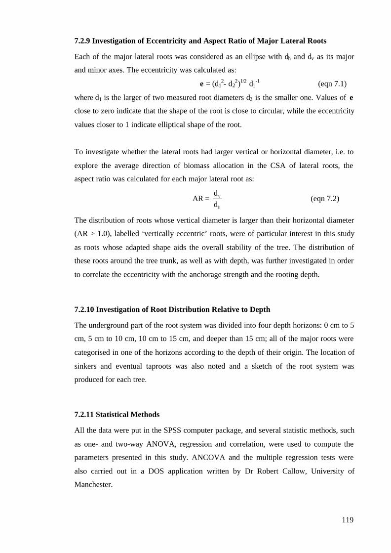
119
7.2.9 Investigation of Eccentricity and Aspect Ratio of Major Lateral Roots
Each of the major lateral roots was considered as an ellipse with dh and dv as its major
and minor axes. The eccentricity was calculated as:
e = (d12- d2
2)1/2 d1-1 (eqn 7.1)
where d1 is the larger of two measured root diameters d2 is the smaller one. Values of e
close to zero indicate that the shape of the root is close to circular, while the eccentricity
values closer to 1 indicate elliptical shape of the root.
To investigate whether the lateral roots had larger vertical or horizontal diameter, i.e. to
explore the average direction of biomass allocation in the CSA of lateral roots, the
aspect ratio was calculated for each major lateral root as:
AR = h
v
dd
(eqn 7.2)
The distribution of roots whose vertical diameter is larger than their horizontal diameter
(AR > 1.0), labelled ‘vertically eccentric’ roots, were of particular interest in this study
as roots whose adapted shape aids the overall stability of the tree. The distribution of
these roots around the tree trunk, as well as with depth, was further investigated in order
to correlate the eccentricity with the anchorage strength and the rooting depth.
7.2.10 Investigation of Root Distribution Relative to Depth
The underground part of the root system was divided into four depth horizons: 0 cm to 5
cm, 5 cm to 10 cm, 10 cm to 15 cm, and deeper than 15 cm; all of the major roots were
categorised in one of the horizons according to the depth of their origin. The location of
sinkers and eventual taproots was also noted and a sketch of the root system was
produced for each tree.
7.2.11 Statistical Methods
All the data were put in the SPSS computer package, and several statistic methods, such
as one- and two-way ANOVA, regression and correlation, were used to compute the
parameters presented in this study. ANCOVA and the multiple regression tests were
also carried out in a DOS application written by Dr Robert Callow, University of
Manchester.
120
7.3. RESULTS
7.3.1 Preliminary Tests
The trenching method revealed that both of the test trees had complex root systems,
with several strong horizontal lateral roots distributed around the stem. Only few sinker
roots were recorded, which originated from some of the laterals, with strongly geotropic
characteristics. Furthermore, both of the test trees had deep tap roots, oval in shape but
far from the ‘I’ beam shaped roots recorded in some previous studies (Mattheck et al.
1995, Stokes et al. 1997).
Both trees failed in their roots as they were pulled over. Soil failure was recorded first
close under the stem, and cracks in the soil then spread towards the edges of the root-
soil plate as the winching continued. There was significant movement in the roots,
accompanied by the development of a complex network of cracks in the soil on the
windward side and loud noise of root snapping after the trunk had been displaced by
cca. 20° from the vertical. Both trees rotated about a point below the tree base, just on
the leeward side, and the leeward laterals were bent and pushed into the soil while the
tap root was bent and pulled up a bit. Consequently, as the test proceeded, windward
laterals came out on the windward side after originally being confined by the
surrounding soil. The tap root of one of the test trees snapped when the trunk had been
displaced approximately 45° from the vertical.
7.3.2 Anchorage Rigidity
The overturning force rose with the displacement of the stem from the vertical. The
rigidity of the anchorage of the 20 trees ranged from 1.97 kNm deg-1 to 4.57 kNm deg-1
(Table 7.1), or on average 3.04±0.79 kNm deg-1 for the whole population. One-way
ANOVA showed that the mean slope of the overturning resistance of outer belt trees
was not significantly (p=0.714) different from the slope of the inner trees. Furthermore,
there was no significant (p=0.890) difference between the rigidity of the trees that failed
in their roots and those ones that failed in their stems.

121
Table 7.1 Mean anchorage rigidity and distribution of the major lateral root CSAin four different directions in the investigated Pinus peuce trees. Values: mean ±SD.
90° 180° 270°Parallel to the
most rigiddirection
MeanAnchorage
Rigidity[kNm deg-1]
0.728±0.368 0.937±0.345 0.873±0.425 3.024±1.334
Root CSA [%] 17.28±3.73 32.20±5.62 22.85±4.47 27.67±5.75
It is worth noting that the slope of the fourth and final pull was significantly
(F1,79=6.125, p=0.019) higher than the other pulls for every tree investigated. This was
always followed by the slope of the second pull, in which the tree was pulled in the
opposite direction from the final pull. Furthermore, the final pull for the outer belt trees
was always from the inside of the stem, i.e. the most rigid direction is the one facing the
outside of the stand. These results justified the chosen direction of pulling as the
strongest and most resistant.
7.3.3 Overturning Tests
As overturning proceeded, the overturning moment initially increased, reached its
maximum and plateaued, before falling once there was a root breakage (recorded in 18
out of 20 investigated trees), or a stem breakage (recorded in 2 out of the 20 investigated
trees). A similar pattern was recorded in the shape of the overturning force vs. time
graph for both inner and outer belt trees.
Overturning moments ranged from 9.20 kNm at an angle of 12.32° to 21.52 kNm at an
angle of 29.5°, or 14.16±3.62 kNm on average at an angle of 21.8±2.71° for the whole
population. The average overturning moment for the inner trees was 13.91±3.49 kNm,
which was lower but not significantly (p=0.559) different than the average overturning
moment for the outer trees: 14.76±4.19 kNm.
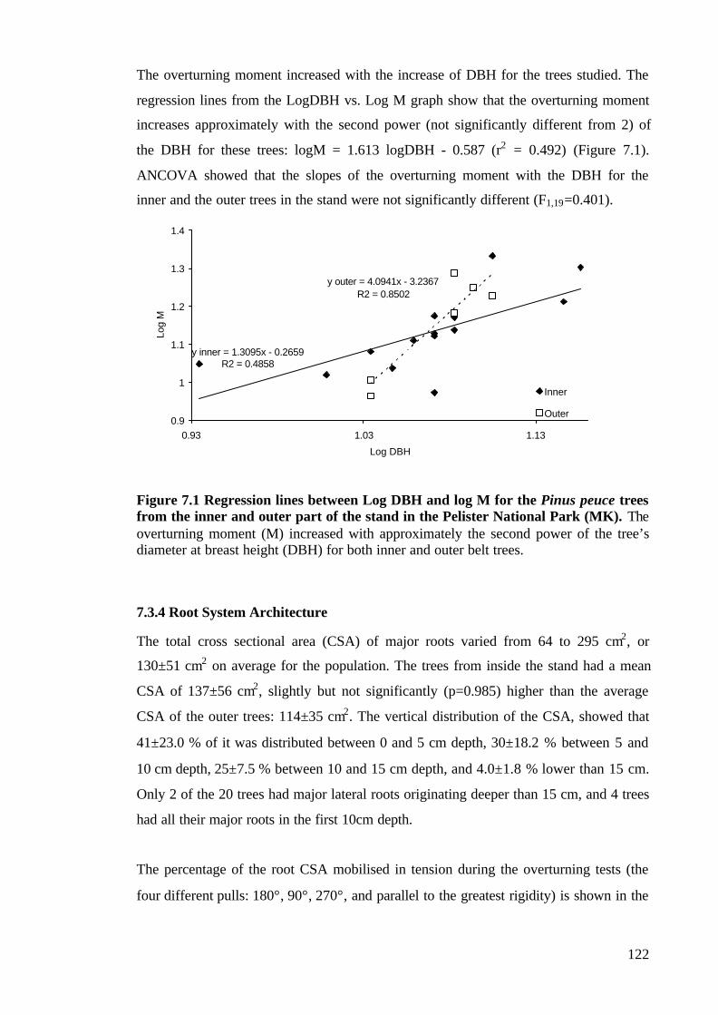
122
The overturning moment increased with the increase of DBH for the trees studied. The
regression lines from the LogDBH vs. Log M graph show that the overturning moment
increases approximately with the second power (not significantly different from 2) of
the DBH for these trees: logM = 1.613 logDBH - 0.587 (r2 = 0.492) (Figure 7.1).
ANCOVA showed that the slopes of the overturning moment with the DBH for the
inner and the outer trees in the stand were not significantly different (F1,19=0.401).
y inner = 1.3095x - 0.2659R2 = 0.4858
y outer = 4.0941x - 3.2367R2 = 0.8502
0.9
1
1.1
1.2
1.3
1.4
0.93 1.03 1.13
Log DBH
Log
M
Inner
Outer
Figure 7.1 Regression lines between Log DBH and log M for the Pinus peuce treesfrom the inner and outer part of the stand in the Pelister National Park (MK). Theoverturning moment (M) increased with approximately the second power of the tree’sdiameter at breast height (DBH) for both inner and outer belt trees.
7.3.4 Root System Architecture
The total cross sectional area (CSA) of major roots varied from 64 to 295 cm2, or
130±51 cm2 on average for the population. The trees from inside the stand had a mean
CSA of 137±56 cm2, slightly but not significantly (p=0.985) higher than the average
CSA of the outer trees: 114±35 cm2. The vertical distribution of the CSA, showed that
41±23.0 % of it was distributed between 0 and 5 cm depth, 30±18.2 % between 5 and
10 cm depth, 25±7.5 % between 10 and 15 cm depth, and 4.0±1.8 % lower than 15 cm.
Only 2 of the 20 trees had major lateral roots originating deeper than 15 cm, and 4 trees
had all their major roots in the first 10cm depth.
The percentage of the root CSA mobilised in tension during the overturning tests (the
four different pulls: 180°, 90°, 270°, and parallel to the greatest rigidity) is shown in the

123
Table 7.1, assuming that the CSA mobilised in tension is the one in the quadrant
opposite from the direction of pulling.
Regression analysis showed that the trees with larger DBH have major roots with larger
CSA (LogCSA = 2.402 LogDBH + 0.454, r2 = 0.435). It can be seen on Figure 7.2 that
this is true both for the inner trees (Log CSA= 2.0486 Log DBH - 0.0808, r2 = 0.424),
and the outer trees (Log CSA = 5.2958 Log DBH - 3.5474, r2 = 0.683). Visual
observation also suggested that the inner trees had more sinker roots and tap roots,
though this observation was not quantified.
y inner = 2.0486x - 0.0808
R2 = 0.424
y outer = 5.2958x - 3.5474
R2 = 0.6827
1.8
1.9
2
2.1
2.2
2.3
2.4
2.5
0.9 0.95 1 1.05 1.1 1.15
Log DBH
Log
CS
A
Inner
Outer
Figure 7.2 Regression lines between Log DBH and Log CSA for the Pinus peucetrees from the inner and outer belt of the stand in the Pelister National Park (MK).The trees with larger DBH have larger CSA in their major lateral roots.
Multi-factorial (two factor) regression analysis showed that together root CSA and the
trunk DBH had a significant (F1,79=11.013, p=0.001, r2=0.515) effect on the overturning
moment, though CSA itself had a non-significant (p=0.192) effect on the resistance of
the whole tree.
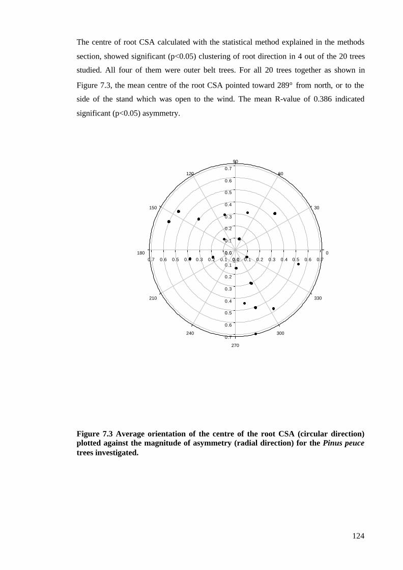
124
The centre of root CSA calculated with the statistical method explained in the methods
section, showed significant (p<0.05) clustering of root direction in 4 out of the 20 trees
studied. All four of them were outer belt trees. For all 20 trees together as shown in
Figure 7.3, the mean centre of the root CSA pointed toward 289° from north, or to the
side of the stand which was open to the wind. The mean R-value of 0.386 indicated
significant (p<0.05) asymmetry.
Figure 7.3 Average orientation of the centre of the root CSA (circular direction)plotted against the magnitude of asymmetry (radial direction) for the Pinus peucetrees investigated.
0.0 0.1 0.2 0.3 0.4 0.5 0.6 0.7
0.0
0.1
0.2
0.3
0.4
0.5
0.6
0.7
0.00.10.20.30.40.50.60.7
0.0
0.1
0.2
0.3
0.4
0.5
0.6
0.7
0
30
60
90
120
150
180
210
240
270
300
330

125
There was positive but non-significant correlation between the root asymmetry ratio
and the anchorage asymmetry ratio (R=0.055, p=0.319), as shown on Figure 7.4.
Therefore asymmetry in the lateral root system did not appear to cause the asymmetry
in the anchorage rigidity.
Figure 7.4 Regression between root asymmetry ratio and the anchorageasymmetry ratio. There was positive but not significant correlation between theasymmetry in the distribution of the major root CSA (root asymmetry ratio) and theasymmetry in the overturning resistance (anchorage asymmetry ratio) around the teetrunk in the investigated Pinus peuce trees.
7.3.5 Eccentricity and Aspect Ratio of Lateral Roots
The average lateral root eccentricity in the studied Macedonian pine trees was
0.410±0.016, indicating that the major lateral roots had adopted elliptic form, i.e. one of
the diameters was greater than the other. The mean aspect ratio of the major lateral roots
was 1.081±0.170, which was significantly (t=5.291, p<0.001) different from 1.In fact, in
76 % of the lateral roots in the investigated trees the major vertical diameter dv was
larger the major horizontal diameter dh.
70% of the roots with larger vertical major diameter were distributed in the direction
perpendicular to the direction of greatest overturning resistance.
Further investigations showed that the lateral roots with larger CSA were more
eccentric. The eccentricity of the vertically eccentric roots was highly significantly
correlated (R=0.461, p<0.001) to the CSA of the root.
y = 0.5413x + 1.0738
R2 = 0.0551
0
1
2
3
4
5
6
7
1 1.5 2 2.5 3 3.5 4 4.5 5
Anchorage Asymmetry Ratio
Roo
t Asy
mm
etry
Rat
io

126
Furthermore, lateral root eccentricity was significantly negatively correlated (R=-0.217,
p=0.038) to the depth of origin of the root, with more eccentric roots being closer to the
soil surface.
7.3.6 Soil Penetrometer Resistance
Soil penetrometer resistance as a marker of soil resistance to root expansion was not
significantly (p=0.483) different for the inner and outer trees. However, the soil
penetrometer resistance increased with depth (Figure 7.5); it was on average
1.066±0.331 MPa at 5 cm depth, 1.535±0.375 MPa at 10 cm depth, and 1.670±0.294
MPa at 15 cm depth. According to the BS 8004: 1986 standard for soils, the soil in the
uppermost soil horizon is classified as firm, and the soil in the lower two horizons as
stiff.
Figure 7.5 Penetrometer resistance of the soil in Pelister National Park [MK]compared to the one in the Jodrell Bank Arboretum [UK]. Error bars indicate ± SD.
7.4. DISCUSSION
The methods developed and used in this study worked well and revealed the root system
morphology and architecture, as well as the anchorage properties in the Pinus peuce
trees investigated. The results of this study revealed many similarities but also
0
0.2
0.4
0.6
0.8
1
1.2
1.4
1.6
1.8
-5 -10 -15
Depth [cm]
Pen
etro
met
er R
esis
tanc
e [M
Pa]
Pelister NP, MK
Jodrell Bank, UK

127
differences between Pinus peuce trees and the related Pinus sylvestris (Mickovski and
Ennos 2002) trees.
The similarities between these two species lie in their respective mechanisms of
anchorage. The anchorage of the investigated Pinus peuce trees proved to be firm, with
values in the overturning tests approximately 55% higher than previously recorded for
Scots pine trees (Mickovski and Ennos 2002). Our results also showed that the trees
with larger trunk DBH were better anchored than the trees with smaller trunk DBH, as
in Pinus sylvestris (Mickovski and Ennos 2002). Furthermore, the resistance of our
Pinus peuce trees to overturning was proportional to the second power of the trunk
diameter, a result similar to that obtained for Pinus sylvestris (Mickovski and Ennos
2002) and also for the tropical tree Mallotus wrayi (Crook and Ennos 1997), both of
which owe their anchorage to their rigid tap roots.
The results of this study on the distribution of root biomass showed agreement with
several previous studies (Rowe 1964, Sutton 1969, Coutts et al. 1998); it was observed
that Macedonian pine trees had several large woody lateral roots, and that most of the
root biomass was allocated to them. Just as in Pinus sylvestris (Mickovski and Ennos
2002), the larger trees had relatively more biomass distributed in their lateral roots than
the smaller ones. The reason for this kind of distribution might be that larger trees are
experiencing higher external forces, and the larger CSA of their roots would dissipate
these forces (e.g. wind blows) and rotational moments more quickly, and provide better
anchorage of the tree.
On the other hand, the distribution of the major lateral roots around the tree stem was, as
the displacement of the centre of the root CSA showed, asymmetrical. The asymmetry
in the investigated Macedonian pine trees is approximately of the same magnitude as in
Pinus sylvestris (Mickovski and Ennos 2002). Judging by the value of the displacement
of the root CSA, it might be deduced that roots with similar diameters are arranged
approximately evenly around the stem in three directions, while the fourth direction is
either lacking roots, or has roots with considerably smaller diameters. This kind of
lateral root distribution was, in fact, recorded for 8 of the investigated 20 trees. An
example of this asymmetry is shown on Plate 7.1.

128
What might have caused this asymmetry? One reason for the asymmetrical distribution
of lateral roots around the tree trunk might be nutrient acquisition. The preferred
clustering direction would be the one where there are more assimilates and less
competition. This was the case with the outer belt Pinus peuce trees which clustered
their lateral roots on the side outside the tree stand, where their lateral spread was less
impeded and where root competition would be lower. Another reason for clustering the
lateral roots in a preferred direction might be connected with tree’s stability
requirements. A larger number of stronger lateral roots would be needed on the side of
the prevailing winds in order to keep the tree from toppling under lateral wind loads.
This proved to be the case of our Pinus peuce trees since the general orientation of the
lateral roots of the investigated trees coincided with the prevailing wind direction.
Having more root biomass distributed in the larger trees as well as trees having more
roots opposite to the direction of the final pull than opposite the other pulling directions
suggested that the root CSA might have an effect on the root anchorage. However, just
as in Scots pine trees (Mickovski and Ennos 2002), the anchorage rigidity of
Macedonian pine was not significantly affected by the distribution of the lateral root
CSA itself, and the correlation between asymmetry in anchorage rigidity and the
asymmetry in the root CSA distribution, although positive, was not statistically
significant.

129
Plate 7.1 Asymmetry in the distribution of major lateral roots around the trunk ofP. peuce at Pelister National Park, Macedonia. The root systems of two of theinvestigated pines show lateral roots of similar diameters arranged approximatelyevenly in three directions, while the fourth direction is lacking roots.

130
What was the cause of the firm anchorage if not the major lateral roots? It is known that
in upright plants at least one rigid element is required to resist rotational moments
transmitted by the stem: either a stiff the root axis into soil (tap root) or a plate of
horizontal roots with sinkers with geotropic characteristics (Ennos 1993). Being a
naturally regenerated stock, our Pinus peuce trees showed a tendency to develop large
diameter straight grained tap roots (Somerville 1979), and had the tap roots and the
sinkers as a major root component in larger depth horizons. Since sinker roots were
recorded in only a few instances in the investigated trees, it is clear that, as in P.
pinaster (Stokes and Guitard 1997) and Pinus sylvestris (Mickovski and Ennos 2002),
the tap roots might be accounted as the major component of the root anchorage in Pinus
peuce.
Alongside the similarities, there were several differences between the investigated Pinus
peuce and related Pinus sylvestris trees. Although both the Macedonian pine and the
Scots pine we investigated were suppressed crown trees and thus expected to have less
proliferated root systems (Wilson 1975), the root system of Pinus peuce was even less
proliferated and branched than the root system of Scots pine (Mickovski and Ennos
2002). This difference in root system morphology might be a result of the differences in
the environmental conditions in which the species is grown, or it might be a part of the
tree’s strategy of adaptation to the soil conditions. How does this difference reflect on
the primary functions of the root system? In providing stability for the tree, the larger
lateral roots in Pinus peuce would provide greater bending rigidity to resist external
forces, since rigidity is proportional with the fourth power of the radius of the root,
while the branched roots recorded in Pinus sylvestris would provide more rapid transfer
of tensile forces into soil (Stokes and Guitard 1997), at the same time having a
reinforcing effect on the soil. Furthermore, knowing that extension growth and
branching are alternative strategies for exploration of soil volumes (Sutton 1969, Harper
et al. 1991), it is clear that the Macedonian pine benefits from its larger linear roots
which are good in exploration for new nutrients while Scots pine grows branched roots
which are more efficient in exploitation.
Another difference between the two related species, closely connected to the root
system morphology, lies in the fact that Pinus peuce was more deeply rooted than the
Pinus sylvestris (Mickovski and Ennos 2002), having approximately only 70 % of the
major lateral roots in the first 10 cm depth compared to the 80 % of the total lateral root

131
CSA in the same depth recorded for Pinus sylvestris. This finding is in agreement with
the results of Sutton (1969), Somerville (1979), and Stokes and Guitard (1997) who also
recorded similar concentration of roots in the uppermost soil layers.
This unevenness in vertical distribution may be related to another difference between
these related species – the eccentricity of the lateral roots. Being more shallowly rooted
and in a weaker soil, the Scots pine roots would be subjected to bending more than the
roots of Macedonian pine though stem sway would have led to change in basal root
cross sectional shape (Fayle 1968, Wilson 1975) in both species. In order to resist the
bending better, the lateral roots might have adopted an elliptical shape that performs
better in bending than the simple circular shape. Indeed, as it is shown on Figure 7.6, the
lateral roots of Pinus peuce were on average 25% less eccentric than the laterals of
Pinus sylvestris (Mickovski and Ennos 2002). Furthermore, the aspect ratio calculations
showed that vertical root diameter was larger than the horizontal diameter in the
majority of major lateral roots, but the mean lateral root aspect ratio of 1.080±0.169 was
significantly (t=3.209, p=0.002) different, in fact 8% lower, than the value of
1.160±0.228 calculated for Pinus sylvestris (Mickovski and Ennos 2002). This is also in
accordance with the results of Nicoll and Ray (1996) who expected that vertically
eccentric roots are less common in deeply rooted trees where strong anchorage is
provided by roots held by a thick matrix of soil.
Figure 7.6 Average eccentricity in vertically eccentric lateral roots in Pinus peucecompared to the one in Pinus sylvestris trees investigated in the Chapter Five ofthis thesis. Error bars indicate + SD.
0
0.1
0.2
0.3
0.4
0.5
0.6
0.7
0.8
species
Ecc
entri
city
P. sylvestris
P.peuce

132
The adaptive secondary root growth of lateral roots caused by external forces might also
compensate against the asymmetrical arrangement of major lateral roots around the
trunk (Coutts et al. 1998). 70 % of the vertically eccentric roots of Macedonian pines
investigated were distributed around the tree trunk in a direction in which the trees
showed lower resistance to overturning. This distribution was similar to the one
recorded in Pinus sylvestris (Mickovski and Ennos 2002), in which approximately 60 %
of the vertically eccentric lateral roots were distributed in the ‘weaker’ direction.
Although the eccentricity and the aspect ratio of the roots in Macedonian pine were far
less extreme than that shown by roots with an ‘I’ or ‘T’ beam shape reported in previous
investigations (Fayle 1968, Hintikka 1972, Wilson 1975, Mattheck et al. 1995, Stokes et
al. 1997), it would still increase bending rigidity and move the hinge point away from
the tree, increasing the length of the lever arm and the resistance to overturning (Nicoll
and Ray 1996).
The evenness of biomass allocation seems to be altered within the structural root system
to provide optimum bending resistance (Nicoll and Ray 1996), but it is also related to
genotype and competition between roots in the early stages of growth (Coutts 1997).
The battle of the roots for water and nutrients, would give a competitive advantage to
the roots close to the surface that would grow faster. In this case it might have been the
taproot that was dominating the root system until the competition for assimilates
between the roots of adjacent trees intensified so that tap root growth was stopped and
might have been occluded by the growth of laterals near to the soil surface and the
assimilates as suggested by Sutton (1969) and Wilson (1975).
Other environmental factors that might have enhanced the unevenness in the vertical
distribution of root biomass might be the soil and the climate. It is shown on Figure 7.5
that the soil on which the trees in this study were planted varies from firm to stiff with
depth, with penetrometer resistance values on average 30% higher than the ones
measured in the Pinus sylvestris study (Mickovski and Ennos 2002). Higher
penetrometer resistance shows a higher level of soil compaction, and, in turn, higher soil
shear strength, which is one of the four major components of the root anchorage (Coutts
1983). Compact soil might have inhibited root growth because of unfavourable moisture
or oxygen relations, low nutrient content or simply because of mechanical impedance,
but the root system remained plastic in its response (Fayle 1968, Sutton 1969) by
producing an overall root system form that would perform primary functions the best.
133
Furthermore, the climate in Macedonia as opposed to the climate in the UK offers less
annual precipitation, which additionally stiffens the soil, as well as reduced disturbance
by extreme winds.
It is evident from the results of this study that the roots of Pinus peuce trees exhibited a
characteristic form and architecture similar, but in some aspects rather different from
that of the related Pinus sylvestris. Major factors that shaped the particular root
architectural pattern include thigmomorphogesis, competition for assimilates, as well as
environmental factors such as the soil and the climate. Further research is needed to
reveal under what circumstances the root architectural pattern as shaped by the
thigmomorphogenic factors and stability and anchorage requirements would prevail
over the selection and competition that has led the root system to exploit and occupy
distinct niches.

134
CHAPTER EIGHT: CONCLUDING REMARKS AND AREAS FOR
FUTURE RESEARCH
The woods are lovely, dark, and deep,But I have promisses to keep,And miles to go before I sleep
Robert Frost (1874-1963)Stopping by the Woods on a Snowy Evening
Previous studies have pointed out the great variability in root form between and within
species, and attributed it to the strong influence of both genetic and environmental
influences (Sutton 1969, Eshel and Waisel 1996). While genetic influences were not a
subject of investigation in this thesis, the variations in root system form and its role in
providing anchorage and stability for the plant were discussed in the previous chapters.
In Chapters Two through Seven different types of root systems were investigated in the
light of their anchorage, looking at the forces they withstand as well as how several
environmental factors influenced the overall shape of the root system. This thesis has
shown that different root systems anchor the plant in a different way using different
strategies which they successfully balance between the root system’s primary roles.
The results of the experiment presented in Chapter Two showed that solid shapes like
bulbs are very well suited to resist vertical upward forces, i.e. uprooting, and shed some
light on the mechanism of anchorage in bulbs – an area that had not previously been
investigated. The depth of embedment and bulb size both had significant effects, but to
different extents in the two types of soil. Increasing depth had a greater effect in sand,
while increasing diameter had a greater effect in agricultural soil. Although the effect of
bulb size and depth might become crucial only if or when there are no roots or the
function of the roots on the basal plate is drastically impaired, it is important to note that
some shapes resist upward forces better than the others and some shapes will be more
advantageous for efficient anchorage than others. The results presented in Chapter Two
showed that the concept of optimal bulb shape for resisting uprooting is viable, and the
uprooting tests on real bulbs confirmed the theoretical predictions about it.
Chapter Two also proved that the soil type as an environmental factor is very important
when considering the anchorage of solid forms like the bulbs. In cohesionless soil it is
necessary to have the root embedded at larger depth to ensure greater soil shear
strength. In cohesive soils, the cohesion acts towards the formation of larger soil failure

135
bodies and larger diameter bulbs would be preferred, allowing efficient formation of a
friction cylinder over the model. It is clear that cohesive soils are better than
cohesionless ones in resisting uprooting, but might pose larger resistance to root
penetration and the downward movement of the bulb by becoming stiffer in dry periods
(Sutton 1969).
Unlike the resistance of roots to vertical forces, resisting lateral forces exerted on the
plant is not possible if the root system of the plant does not have at least one rigid
element able to transfer the overturning moments into the soil. A model study presented
in Chapter Three showed that the simplest models of tap root-dominated root systems
increase their resistance to overturning with the third and second power of the
embedment depth in cohesionless and in cohesive soil respectively, similar to the
findings of Crook and Ennos (1996). Anchorage strength of a tap root dominated root
system will be maximised with minimum investments in structural material if the rigid
tap root could be extended to the largest possible depth. Isometric scaling of the tap root
length, being directly proportional to the diameter of the stem proved to provide
efficient anchorage at minimum cost of structural material just as predicted by theory
(Ennos 1993). However, the strength considerations (Ennos 1993) of the root material
and the surrounding soil limit the size and shape of the rigid root, and adaptations such
as root taper would reduce the cost of anchorage by using most of the available material
where the stresses are the highest – in the parts where lateral bending forces and tension
are transmitted from the stem to the soil.
As they grow older the root systems of trees change from being tap root dominated to
being plate root systems. Even within species, the root system form becomes
increasingly variable with age as it responds to a number of stimuli. Sutton (1969)
referred to this variability as evidence of the power of the environment to shape root
system form. The results of the study presented in Chapter Four have shown the effects
of soil compaction and temperature, two of the most important environmental factors,
on the development of the root system in two species of young pines. Similarly to some
previous studies (Bengough and Mullins 1990, Plaut et al. 1996) it was shown that the
rate of root axial development in both investigated species decreased with an increase in
soil compaction, though the lateral proliferation of their roots systems was not
significantly affected by the soil consistency. On the other hand, a temperature of
around 15°C seemed to be optimal for the root elongation rate since the increase in axial

136
length of the roots of both species was largest at this temperature. The proliferation of
new lateral roots, the ones that are expected to play a role in the anchorage and stability
of the tree as it ages (Coutts 1986) was not impeded by increased soil compaction or
higher temperature. Branching and development of lateral roots would normally
increase the overall stability of the plant, and would change the mechanism of root
failure under lateral loads so that the lateral roots then act as guy ropes under tension.
Furthermore, the elliptical or eccentric cross sections of the major lateral roots in
mechanically flexed young pines recorded in this chapter, but also in older pines in the
field (Chapters Six and Seven), clearly contribute to the increase in overall stability of
trees by increasing their flexural rigidity in the vertical plane. This improves anchorage
both by increasing the hinge component of anchorage and also increasing the size of
root plate they can support (Coutts 1983a,b).
Chapter Five showed that mechanical stimulation also acts as a factor in shaping the
root systems of plants. Apart from the changes caused to the parts of the tree above
ground, unidirectional periodical flexing induced an increase in total root CSA and
larger biomass allocation to the roots parallel to the plane of flexing which, in turn,
resulted in a larger number of major lateral roots with larger CSA in the plane of flexing
just as in several previously investigated species (Stokes et al. 1995, Nicoll and Ray
1996). Since there were no significant differences in root:shoot ratio or the mechanical
properties of wood between flexed and unflexed trees in this study, the increase in the
lateral resistance in flexed Pinus sylvestris was associated with the greater proportion of
total root biomass allocated to the proximal major lateral roots, as in Pinus radiata
(Watson and Tombleson 2002). The change of biomass allocation provided better
access to the available nutrients by increasing the lateral root CSA in flexed trees. The
significant increase of the lateral root CSA in the direction of the mechanical
perturbation in investigated pines was also an adaptive mechanism for improvement of
the tree’s anchorage and it might be considered as an early indicator of emerging tree
stability (Watson and Tombleson 2002).
However, Chapters Six and Seven have shown that lateral roots in older trees are not the
major source of root anchorage in either of the Pinus species investigated; although in
both species a certain asymmetry in the distribution of major lateral root CSA was
recorded, it was not significantly correlated to the asymmetry in anchorage. The root
system asymmetry recorded in both Macedonian and Scots pines (Chapters Six and

137
Seven, respectively) might have been caused by other factors such as: the tree’s stability
requirements; the soil mechanical impedance that increased with depth; or, more likely,
the competition for assimilates between roots. In the light of these, the resistance of the
windward sinker and tap roots to uprooting as well as their resistance to bending seemed
to provide the vast majority of the anchorage resistance in both pine species, just as in
the lateral root dominated systems studied in the past (Crook and Ennos 1996, Crook et
al. 1997).
Understanding the finer aspects of root system morphology and architecture can also
help us understand the anchorage of different types of root systems. Different types of
root systems have been investigated and presented in Chapters Two through Seven of
this thesis, and a large variety in the form and shape of the individual members of these
root systems was recorded. These natural adaptations help the root system in more
efficient performance of its primary functions.
Differences in rooting and in anchorage mechanisms are important for competition
between species. At a specific location these differences would allow one genotype to
grow better than the other just because of a better rooting strategy. From the point of
view of satisfying the plant’s need for nutrients the rooting strategies range from longer,
stronger and faster growing lateral roots which provide better nourishment but have less
selective capacity (Scots pines in Chapters Four and Six), and fine, slowly grown roots
that better exploit soil volume for nutrients and offer better resistance to limiting factors
such as extreme temperatures and soil compaction (Macedonian pines in Chapters Four
and Seven).
When providing stability for the tree, the differences in root system morphology reflect
the different strategies adopted by different species. The larger lateral roots in Pinus
peuce (Chapter Seven), for example, would provide greater bending resistance in
resisting external lateral forces since rigidity is proportional to the fourth power of the
root radius. On the other hand, the branched roots of Pinus sylvestris are able to transfer
the tensile forces from external influences very rapidly into the soil, and at the same
time act as soil reinforcement.
It is clear that the major factors that shape the particular root morphological pattern
include thigmomorphogenesis, competition for assimilates, as well as environmental
138
factors such as soil properties and climate. Furthermore, root system form depends and
is largely affected by the type of anchorage required by a plant, on its size and on its
taxonomic position (Ennos 1993), and anchorage considerations rather than absorption
considerations are the ones which effectively constrain the overall shape of root
systems.
Because of the many factors involved, the developmental processes of root systems are
difficult to understand without an appropriate model. However, the studies presented in
Chapter Two and Chapter Three of this thesis have shown that explaining the anchorage
behaviour of even very simple physical models of root systems can be complex and
requires an interdisciplinary approach. Highlighting the areas where more research is
needed to deepen our knowledge would help in the attempts to model more complicated
systems. In this context, a more detailed experimental modelling of root systems under
horizontal and vertical forces is needed in order to explain their anchorage behaviour.
Ideally, these models would investigate the influence of natural adaptations such as the
root taper and branching on the stability of the system and thus complement the mostly
theoretical knowledge on this subject.
Viable numerical models of the anchorage behaviour of different types of root systems
are expected to improve our knowledge of the areas of the tree stability where little is
known. Devising numerical root development models based on experimental data
obtained from long-term observations is crucial for providing the necessary real-model
similarity. Eventually, it might be possible to link root development models to tree
stability models, perhaps to the existing root anchorage models (Blackwell et al. 1990),
or even to the models of the other root functions (Dunbabin et al. 2002).
On the other hand, appropriate numerical models of root development might be used as
an input for Finite Element Method (FEM) – based programs, such as for example SAP
2000© or PLAXIS©, which are able to present and calculate the stress-strain
relationships of all members of the root system and in the surrounding environment
under different types of loads. In this manner the changes in the anchorage behaviour of
the root system might be monitored as it grows. It would be feasible to see how single
roots and groups of roots interact with soil, as well as to explore how soil type affects
root growth and anchorage. Doing this might also help fill in some of the gaps in our
knowledge about root anchorage.

139
In order to gain more knowledge on the role of the root system with regards to tree
stability and anchorage, further studies are needed on the influence of the external
mechanical and environmental factors on the form and strength of the root system,
which in turn influence the overall stability of the tree. It is well known how trees
respond to intermittent or continuous winds (Telewski 1995) but it is not known how
much the flexing-induced changes alter tree’s resistance to windthrow. In order to
answer this problem more detailed research is needed on young trees grown in the
natural environment together with their immediate responses and adaptations of their
root growth to mechanical perturbation, perhaps by monitoring the growth rings in the
major roots. Future studies should also include investigations of the root systems of as
more new species as possible, and should answer how stable plants really are.
Studies of this type are needed to help give practical advice to foresters and
arboriculturalists in order to improve the management of different trees and to avoid
their potential loss. Trees with firm anchorage, and with root systems that respond faster
to external loads might be selected where wind damage has to be reduced. Furthermore,
selecting trees that develop a high root:shoot ratio and a more even biomass distribution
between the thicker major lateral roots might effectively reduce via windthrow.

140
REFERENCES:
Abdalla, A.M., Hettiaratchi, D.R.P, and Reece, A.R. 1969. The mechanics of root
growth in granular media. Journal of Agricultural Engineering Research 14, 248-263.
Adams, W.R. 1934. Studies in tolerance of New England forest trees. XI. The influence
of soil temperature on the germination and development of white pine seedlings. Bull.
Vt. Agric. Exp. Stn. 379, 18-36.
Balla, A. 1961. The resistance to breaking out of mushroom foundations for pylons.
Proceedings 5th Int’l Conference on Soil Mechanics and Foundation Engineering Paris,
France.
Barley, K.P. 1962. The effects of mechanical stress on the growth of roots. Journal of
Experimental Botany 13, 95-110.
Barley, K.P. 1963. Influence of soil strength on growth of roots. Soil Science 18, 499-
503.
Barley, K.P., and Graecen, E.L. 1967. Mechanical resistance as a soil factor
influencing the growth of roots and underground shoots. Advances in Agronomy 19,
118-121.
Barney, C.W. 1951. Effects of soil temperature and light intensity on root growth of
loblolly pine seedlings. Plant Physiology 26, 146-163.
Bengough, A.G., and Mullins, C.E. 1990. Mechanical impedance to root growth: A
review of experimental techniques and root responses. Journal of Soil Science 41, 341-
358.
Bengough, A.G., Croser, C., Pritchard, J. 1997. A biophysical analysis of root
growth under mechanical stress. Plant and Soil 189, 155-164.
Bennie, A.T.P. 1996. Growth and mechanical impedance. In Plant Roots – The hidden
half, Weisel, Y., Eshel, A., and Kafkafi, U. (eds). 2nd edition, Marcel Dekker Inc., New
York, pp453-469.
Bingham, I.J. 2001. Soil-root-canopy interactions. Annals of Applied Biology 138(2),
243-251.
Blackwell, P.G., Renolls, K., and Coutts, M.P. 1990.A root anchorage model for
shallowly rooted Sitka spruce. Forestry 63, 73-91.
Boone, M.P. 1975. Load tests on model ground anchors, Faculty of Sciences, Victoria
University of Manchester, MSc. Thesis.

141
Bowen, G.D. 1991. Soil temperature, root growth and plant function. In Plant Roots –
The hidden half, Weisel, Y., Eshel, A., and Kafkafi, U. (eds). 1st edition, Marcel Dekker
Inc., New York, pp309-330.
Broms, B.B. 1964. Lateral resistance of piles in cohesionless soil. Jour. of Soil Mech.
and Found. Div. Proc. of ASCE. SM3, 123-156.
Broms, B.B. 1964. Lateral resistance of piles in cohesive soil. Jour. of Soil Mech. and
Found. Div. Proc. of ASCE 90, 27-63.
Broms, B.B. 1981. Precast piling practice. Thomas Telford Ltd, London.
Brouwer, R. and Hoagland, A. 1964. Responses of bean plants to root temperatures. II
Anatomical aspects. Meded. Inst. Biol. Scheid. Onderz. Landb. Gewass. 236, 23-31.
Brüchert, F., Speck, T., Becker, G. 1997. The mechanics of standing trees: Picea
abies (L.(Karst.)) under differing silvicultural treatments. In Plant biomechanics
(conference proceedings I: papers, Jeronimidis, G., and Vincent, J.F.V. (eds). Centre
for biomimetics, University of Reading, pp23-30.
Cooper, A.J. 1973. Root temperature and plant growth. Commonwealth Agricultural
Bureaux, Slough.
Coutts, M.P. 1983. Root architecture and tree stability. Plant and Soil 71(1-3), 171-
188.
Coutts, M.P. 1983. Development of the structural root system of Sitka spruce. Forestry
56, 1-16.
Coutts, M.P. 1986. Components of tree stability in Sitka spruce on peaty gley soil.
Forestry 59 (2), 173-197.
Coutts, M.P. 1987. Developmental processes in the tree root systems. Canadian
Journal of Forestry Research17, 761-767.
Coutts, M.P., Nielsen, C.C.N., Nicoll, B.C. 1998. The development of symmetry,
rigidity and anchorage in the structural root systems of conifers. In The supporting roots
of trees and woody plants: form, function and physiology, Stokes, A. (ed), Kluwer
Academic, Dordrecht, Holland, pp218-230.
Coutts, M.P., Walker, C., Burnard, A.C. 1990. Effects of establishment method on
root form of lodgepole pine and Sitka spruce and on the production of adventitious
roots. Forestry 63, 143-159.
Crook, M.J. and Ennos, A.R. 1993. The mechanics of root lodging in winter wheat,
Triticum aestivum, L. Journal of Experimental Botany 44, 1219-1224.
Crook, M.J. and Ennos, A.R. 1996. The anchorage mechanics of deep rooted larch,
Larix europea x L. japonica. Journal of Experimental Botany 47 (303), 1509-1517.

142
Crook, M.J. and Ennos, A.R. 1997. Scaling of anchorage in the tap rooted tree
Mallotus wrayi. In Plant biomechanics (conference proceedings I: papers). Jeronimidis,
G., Vincent, J. F. V. (eds), Centre for biomimetics, University of Reading, pp31-36.
Crook, M.J., Ennos, A.R., Banks, J.R. 1997. The function of buttress roots: a
comparative study of the anchorage systems of buttressed (Aglaia and Nephelium
ramboutan species) and non-buttressed (Mallotus wrayi) tropical trees. Journal of
Experimental Botany 48(314), 1703-1716.
Davis, G.R. 1984. Effect of soil compaction on root growth of Pinus radiata D. Don. In
Proceedings of the Symposium on Site and Productivity of Fast Growing Plantations,
vol. 2, South Africa, pp871-881.
Dexter, A.R. 1987. Compression of soil around roots. Plant and Soil 97, 401-406.
Dexter, A.R. 1987. Mechanics of root growth. Plant and Soil 98, 303-312.
Downes, G.M., Moore, G.A., Turvey, N.D. 1994. Variations in response to induced
stem bending in seedlings of Pinus radiata. Trees 8(3), 151-159.
Drew, M.C. 1986. Function of root tissues in nutrient and water uptake. In Root
development and function, Gregory, P.J., Lake, J.V., Rose, D.A. (eds). SEB seminar
series no. 30, 71-102.
Dunbabin, V. M., Diggle, A. J., Rengel, Z., van Hugten, R. 2002. Modelling the
interactions between water and nutrient uptake and root growth. Plant and Soil 239, 19-
38.
Eavis, B.W. 1967. Mechanical impedance to root growth. Agricultural Engineering
Symposium, Silsoe. Paper 4/F/39.
Ennos, A.R. 1989. The mechanics of anchorage in seedlings of sunflowers Hellianthus
annuus. New Phytologist 113, 185-192.
Ennos, A.R. 1990. The anchorage of leek seedlings: the effect of root length and soil
strength. Annals of Botany 65, 409-416.
Ennos, A.R. 1991. The mechanics of anchorage in wheat Triticum aestivum L. I. The
anchorage of wheat seedlings, Journal of Experimental Botan y42, 1607-1613.
Ennos, A.R. 1993. The scaling of root anchorage. Journal of Theoretical Botany 161,
61-75.
Ennos, A.R. 2000. The mechanics of root anchorage. Advances in Botanical Research
33, 123-128.
Ennos, A.R., Crook, M.J., Grimshaw, C. 1993. The anchorage mechanics of maize
Zea mays. Journal of Experimental Botany 44, 147-153.

143
Ennos, A.R. and Fitter, A.H. 1992. Comparative functional morphology of the
anchorage systems of annual dicots. Functional Ecology. 6, 71-78.
Eshel, A. and Waisel, Y. 1996. Multiform and multifunction of various constituents of
one root system. In Plant Roots – the hidden half, Waisel, Y., Eshel, A, Kafkafi, U.
(eds). 2nd ed. Marcel Dekker Inc., New York, USA, pp231-245.
Fayle, D.C.F. 1968. Radial growth in tree roots. Technical report no. 9. Faculty of
Forestry, University of Toronto, Canada.
Fayle, D.C.F. 1975. Extension and longitudinal growth during the development of red
pine root systems. Canadian Journal of Forestry Research 5, 109-121.
Fitter, A. 1996. Characteristics and functions of root systems. In Plant Roots - the
hidden half, Waisel, Y., Eshel, A., Kafkafi, U. (eds). 2nd ed. Marcel Dekker Inc., New
York, USA, pp1-20.
Fraser, A.I. 1962. The soil and roots as factors in tree stability. Forestry 35, 117-127.
Fredericksen, T.S., Hedden, R.L., Williams, S.A. 1993. Testing loblolly-pine wind
firmness with simulated wind stress. Canadian Journal of Forestry Research 23(9),
1760-1765.
Fredericksen, T.S., Hedden, R.L., Williams, S.A. 1994. Effect of stem bending on
hydraulic conductivity and wood strength of loblolly-pine. Canadian Journal of
Forestry Research 24(3), 442-446.
Gartner, B.L. 1994. Root biomechanics and whole plant allocation patterns: responses
of tomato to simulated wind. Journal of Experimental Botany 45, 1647-1654.
Gere, G.M., and Timoschenko, S.P. 1991. Mechanics of materials. Chapman and
Hall, London.
Glinski, J., and Lipiec, J. 1990. Soil physical conditions and plant roots. CRC press,
Boca Raton, Florida.
Goodman, A.M., and Ennos, A.R. 1996. A comparative study of the response of the
roots and shoots of sunflower and maize to mechanical stimulation. Journal of
Experimental Botany 47, 1499-1507.
Goodman, A.M. and Ennos, A.R. 1997. The response of roots to mechanical
stimulation. In Plant biomechanics (conference proceedings I: papers). Jeronimidis, G.,
Vincent, J. F. V. (eds), Centre for biomimetics, University of Reading, pp359-368.
Goodman, A.M., and Ennos, A.R. 1998. Responses of the root systems of sunflower
and maize to unidirectional stem flexure. Annals of Botany 42, 347-357.

144
Goodman, A.M., and Ennos, A.R. 1999. The effects of soil bulk density on the
morphology and anchorage mechanics of the root systems of sunflower and maize.
Annals of Botany 83. 293-302
Goodman, A.M., and Ennos, A.R. 2001. The effects of mechanical stimulation on the
morphology and mechanics of maize roots grown in an aerated nutrient solution.
International Journal of Plant Sciences 162 (4), 691-696.
Goodman, A.M., Crook, M.J., Ennos, A.R. 2001. Anchorage mechanics of the tap
root system of winter-sown oilseed rape (Brassica napus L.). Annals of Botany 87, 397-
404.
Goss, M. J. 1977. Effects of mechanical impedance on root growth in barley (Hordeum
vulgare L.). I. Effects on elongation and branching of seminal roots. Journal of
Experimental Botany 28, 96-111.
Goss, M.J. and Russel, R.S. 1980. Effects of mechanical impedance on root growth in
barley (Hordeum vulgare L.). III. Observations on the mechanism of response. Journal
of Experimental Botany 31, 577-588.
Graecen, E.L. 1960. Water content and soil strength. Journal of Soil Science 11, 313-
333.
Graecen, E.L. 1986. Root response to soil mechanical properties. Transactions of the
13th Congress of the ISSS, Hamburg, 5, 20-47.
Graecen, E.L., Barley, K.P., Farell, D.A. 1968. Mechanics of root growth in soils with
particular reference to the implications for root distribution. In Root Growth,
Whittington, W.J. (ed), Butterworth, London, pp256-269.
Harper, J.L., Jones, M., Sackville Hamilton, N.R. 1991. The evolution of roots and
the problems of analysing their behaviour. In Plant root growth – an ecological
perspective, Atkinson, D. (ed.). Blackwell scientific publications, Oxford, pp3-22.
Hintikka, V. 1972. Wind-induced root movements in forest trees. Commonwealth
Institute Forestiere Fenniae 76, 56-63.
Jacobs, M.R. 1954. The effect of wind sway on the form and development of Pinus
radiata D. Don. Australian Journal of Botany 2, 35-45.
Jaffe, M.J. 1973. Thigmomorphogenesis: The response of plant growth and
development to mechanical stimulation. Planta 114, 143-157.
Johnson, D.A. and Aguirre, L. 1991. Effect of water on morphological development
in seedlings of three range grasses: root branching patterns. Journal of Range
Management 44, 355-360.

145
Kellog, R.M. and Steucek, G.L. 1977. Motion induced growth effects on Douglas Fir.
Canadian Journal of Forestry Research 7, 94-99.
Köstler, J.N., Brückner, E., and Bibelreither, H. 1968. Die Wurzeln der Waldbäume.
Paul Parey Verlag, Hamburg.
Kramer, D. 1983. Genetically determined adaptations in roots to nutritional stress.
Correlation of structure and function. Plant and Soil 72(2-3), 167-173.
Lindstrom, A., and Rune, G. 1999. Root deformation in plantations of container-
grown Scots pine trees: effects on root growth, tree stability and stem straightness. Plant
and Soil 217(1-2), 29-37.
MacLeod, R.D., and Cram, W.J. 1996. Forces exerted by tree roots. Arb.Res.Inf.Not.
134/96/EXT. AAIS, Farnham, UK.
Mardia, K.V. 1972. Statistics of directional data. Academic press, London.
Mattheck, C. 1991. Trees: the mechanical design. Springer-Verlag, Berlin.
Mattheck, C., Bethge, K., Albrecht, W. 1995. Failure modes of trees and related
failure criteria. In Wind and Trees, Coutts, M.P., Grace, J. (eds). Cambridge University
Press, Cambridge UK, pp195-203.
McMichael, B. I., and Burke, J.J. 1996. Temperature effects on root growth. In Plant
Roots – the hidden half, Waisel, Y., Eshel, A., and Kafkafi, U. (eds). 2nd edition, Marcel
Dekker Inc., New York, pp201-206.
Mickovski, S.B. and Ennos, A.R. 2002. A morphological and mechanical study of the
root systems of suppressed crown Scots pine Pinus sylvestris. Trees 16, 274-280.
Misra, R.K. 1997. Maximum axial growth pressures of the lateral roots of pea and
eucalypt. Plant and Soil 188, 161-170.
Moore, J.R. 2000. Differences in maximum resistive bending moments of Pinus radiata
trees grown on a range of soil types. Forest Ecology and Management 135(1-3), 63-71.
Neel, P.L., and Harris, R.W. 1971. Motion induced inhibition of elongation and
induction of dormancy in liquidambar. Science 173, 58-59.
Nicoll, B.C., and Armstrong, A. 1998. Development of Prunus root systems in a city
street: pavement damage and root architecture. Arboricultural Journal l22, 259-270.
Nicoll, B.C., and Ray, D. 1996. Adoptive growth of tree root systems in response to
wind action and site conditions. Tree physiology 16, 891-898.
Nicoll, B.C., Easton, E.P., Milner, A.D., Walker, C., Coutts, M.P. 1995. Wind
stability factors in tree selection: distribution of biomass within root systems of Sitka
spruce clones. In Wind and Trees, Coutts, M.P., Grace, J. (eds). Cambridge University
Press, Cambridge UK, pp276-292.

146
Nielsen, K.F. 1974. Roots and root temperature. In Plant root and its development,
Carson, E.W. (ed.). University press of Virginia, Charlotesville, VA, pp293-335.
Niklas, K.J., Molina-Freaner, F., Tinoco-Ojanguren, C., Paolillo, D.J.Jr. 2002. The
biomechanics of Pachycereus pringlei root systems. American Journal of Botany 89(1),
12-21.
Norbury, D.R., Child, G.H., Spink, T.W. 1986. Soil and rock description. Site
Investigation Practice, Engineering Geology Special Publication no.1.
Pagès, L. 1995. Growth patterns of the lateral roots of young oak (Quercus robur) tree
seedlings. Relationship with apical diameter. New Phytologist 130(4), 503-509.
Payne, D. 1973. Soil mechanical properties and root growth. Journal of Science of
Food Agriculture 25, 235-242.
Pejoski, B. and Todorovski, S. 1959. Les etudes comparatives des proprietes physico-
mechaniques des bois du pin peuce et du sapin de Pelister. In Codex of the Pelister
National Park (book 1), Kiro Dandaro, Bitola, Macedonia, pp134-165.
Peltola, H., Kellom←← ki, S., Hassinen, A., Granander, M. 2000. Mechanical stability
of Scots pine, Norway spruce and birch: an analysis of tree-pulling experiments in
Finland. Forest Ecology and Management 135(1-3), 145-153.
Phares, R.E., Kolar, C.M., Hendricks, T.R., Ashby, W.C. 1974. Motion induced
effects on growth of Black Walnut, Silver Maple and Sweetgum seedlings under two
light regimes. Proc. 3rd N.American Forest Biol. Workshop, Reid, C.P., Fecher, C.H.
(eds), p386.
Plaut, Z., Newman, M., Federman, E., Grava, A. 1997. Response of root growth to a
combination of three environmental factors: water stress salinity and soil compaction. In
Biology of root formation and development, Altman Y., Weisel, Y. (eds). Plenum press,
New York, pp243-248.
Popnikola, N. 1959. The Pelister National Park: characteristics, problems, and
arrangement. In Codex of the Pelister National Park (book 1), Kiro Dandaro, Bitola,
Macedonia, pp7-33.
Poulos, H.G. and Davis, E.H. 1980. Pile foundation analysis and design. John Wiley
& Sons, New York, USA.
Pütz, N. 1991. Die Zugbewegungstypen bei den Monokotylen. Bot. Jahrb. Syst. 112(3),
347-364.
Pütz, N. 1992. Das Verhaeltnis von Bewegung und Wurzelkraft bei Monokotylen.
Beitraege zur Biologie der Pflanze 67(2), 173-191.
147
Pütz, N. 1992. Underground movement by contractile roots. Root Ecology and its
Practical Applications, 3rd ISSR Symposium, Vienna, Austria, pp669-672.
Pütz, N. 1993. Underground plant movement I. The bulb of Nothoscordium inodorum
(Alliaceae). Botanica Acta 106, 338-343.
Pütz, N. 1996. Underground plant movement IV. Observance of the behaviour of some
bulbs with special regard to the induction of root contraction. Flora 191, 313-319.
Quirk, J.T., Smith, D.M., Freese, F. 1975. Effects of mechanical stress on growth and
anatomical structure of red pine (Pinus resinosa Ait.): torque stress. Canadian Journal
of Forestry Research 5, 691-699.
Rees, A.R. 1972. The growth of bulbs. Applied aspects of the physiology of ornamental
bulbous crop plants. Academy Press, London.
Rees, D.J., and Grace, J. 1980. The effects of shaking on extension growth of Pinus
contorta Douglas. Forestry 53, 145-153.
Robertson, A.I. 1991. Centroid of wood density, bole eccentricity, and tree ring width
in relation to vector winds in wave forests. Canadian Journal of Forestry Research 21,
73-82.
Rowe, J.S. 1964. Studies in rooting of White spruce. Project H-131, 2nd progress report.
Mimeo Dep. For. Can. No. 64-H-13, 23.
Rundel, P.W., and Nobel, P.S. 1991. Structure and function in desert root systems. In
Plant root growth, Atkinson, D. (ed.), Blackwell Scientific Publications, Oxford,
pp349-378.
Russell, R.S. 1977. Plant root systems: their function and interaction with soil.
McGraw-Hill, London.
Sands, R., Graecen, E.L., Gerard, C.J. 1979. Compaction of sandy soils in radiata
pine forests. I. A penetrometer study. Australian Journal of Soil Research 17, 101-107.
Smit, A.L., Bengough, A.G., Engels, C., van Noordwijk, M., Pellerin, S., van de
Geijn, S.C. (eds) 2000. Root methods: a handbook. Springer Verlag, Berlin.
Somerville, A. 1979. Root anchorage and root morphology of Pinus Radiata on a range
of ripping treatments. New Zealand Journal of Forest Science 9, 294-315.
Spoor, G. 1973. Fundamental aspects of cultivations. MAFF Technical Bulletin 29: Soil
physical conditions and crop production.
Stokes, A. 1995. The shape of tree root systems affects root wood strength. Technical
report no 5518, Forschungszentrum Karlsruhe, Germany

148
Stokes, A. 1999. Strain distribution during anchorage failure of Pinus pinaster Ait. at
different ages and tree growth response to wind induced root movement. Plant and Soil
217, 17-27.
Stokes, A., and Guitard, D. 1997. Tree root response to mechanical stress. In Biology
of root formation and development , Altman, A., and Waisel, Y. (eds), Plenum Press,
New York, pp227-236.
Stokes, A., Fitter, A.H., Coutts, M.P. 1995. Responses of young trees to wind and
shading: effects on root architecture. Journal of Experimental Botany 46, 21-26.
Stokes, A., Martin, F., Sacriste, S., Fourcaud, T. 1997. Adaptation of tree roots to
wind loading – the relationship between mechanical behaviour and wood formation. In
Plant biomechanics (conference proceedings I: papers), Jeronimidis, G. and Vincent,
J.F.V. (eds). Centre for biomimetics, University of Reading, pp339-346.
Stokes, A., Nicoll, B.C., Coutts, M.P., Fitter, A.H. 1997. Responses of young Sitka
spruce clones to mechanical perturbation and nutrition: effects on biomass allocation,
root development, and resistance to bending. Canadian Journal of Forestry Research
27, 1049-1057.
Stokes, A., Ball, J., Fitter, A.H., Brain, P., Coutts, M.P. 1996. An experimental
investigation of the resistance of model root systems to uprooting. Annals of Botany 78,
415-421.
Sutton, R.F. 1969. Form and development of conifer root systems. Commonwealth
Agricultural Bureaux, Tech. Comm. No.7.
Taylor, H.M., and Gardner, H.R. 1963. Penetration of cotton seedling tap roots as
influenced by bulk density, moisture content and strength of soil. Soil Science 96, 153-
156.
Taylor, H.M., and Ratliff, L.F. 1969. Root elongation rates of cotton and peanuts as a
function of soil strength and water content. Soil Science 108, 113-119.
Taylor, H.M., Huck, M.G., Klepper, B. 1972. Root development in relation to soil
physical conditions. In Optimizing the soil physical environment toward greater crop
yields, Hilel, D. (ed.). Academic Press, New York, pp55-77.
Telewski, F.W. 1989. Structure and function of flexure wood in Abies fraseri. Tree
physiology 5, 113-122.
Telewski, F.W. 1990. Growth, wood density, and ethylene production in response to
mechanical perturbation in Pinus taeda. Canadian Journal of Forestry Research 20,
1277-1282.

149
Telewski, F.W. 1995. Wind induced physiological and developmental responses in
trees. In Wind and trees, Coutts, M.P., Grace, J. (eds). Cambridge University Press,
pp237-263.
Telewski, F.W., and Jaffe, M.J. 1986. Thigmomorphogenesis: field and laboratory
studies of Abies fraseri in response to wind or mechanical perturbation. Physiologia
Plantarum 66, 211-218.
Teskey, R.O., and Hinckley, T.M. 1981. Influence of temperature and water potential
of root growth of white oak. Physiologia Plantarum 52, 363-369.
Tomlinson, M.J. 1977. Pile design and construction practice. Viewpoint publ.,
London.
Tsegaye, T., and Mullins, C.E. 1994. Effect of mechanical impedance on root growth
and morphology of two varieties of pea (Pisum sativum L.). New Phytologist 126, 707-
713.
Vallinger, E., Lundqvist, L., Sundberg, B. 1994. Mechanical stress during dormancy
stimulates stem growth of Scots pine seedlings. Forest Ecology and Management 67 (1-
3), 299-303.
Vallinger, E., Lundqvist, L., and Sundberg, B. 1995. Mechanical bending stress
applied during dormancy and (or) growth stimulates stem diameter growth of Scots pine
seedlings. Canadian Journal of Forestry Research 25(6), 886-890.
Vincent, J.F.V. 1992. Biomechanics-materials: a practical approach. Oxford: 165-IRL
Press at Oxford University Press.
Wästerlund, I. 1985. Compaction of till soils and growth tests with Norway spruce and
Scots pine. Forest Ecology and Management 11, 171-177.
Watson, A.J. 2000. Wind-induced forces in the near-surface lateral roots of radiata
pine. Forest Ecology and Management 135(1-3), 133-142.
Watson, A.J., and Tombleson, J.D. 2002. Toppling in juvenile pines: A comparison of
the root system characteristics of direct-sown seedlings, and bare-root seedlings and
cuttings. Plant and Soil 239(2), 187-196.
Wilson, B.F. 1975. Distribution of secondary thickening in tree root systems. In The
development and function of roots, Torrey, J.G., Clarkson, D.T. (eds), Academic Press,
London, pp39-51.