Embed Size (px)
Citation preview
FEW THOUGHTS ON THE NUMERICAL SIMULATION OF
SOIL, STRUCTURE AND EARTHQUAKE INPUT
Anastasios Sextos a
a Assistant Professor, Aristotle University of Thessaloniki, Department of Civil Engineering, Division of Structural Engineering, [email protected]
1 INTRODUCTION
The importance of soil-structure-interaction (SSI) for the assessment of the dynamic response of bridges has been widely recognized during the last decades in numerous research studies. Nowadays, there is strong analytical and experimental evidence to support that soil-structure interaction phenomena depend on soil properties, soil stratification and topography as well as on the earthquake input frequency content and amplitude, while SSI may drastically affect the overall inelastic dynamic response of bridge structures. Moreover, a large variety of very powerful computational tools is available which utilize an enormous amount of computational power that was certainly not available just few years ago. On the other hand, despite the significant progress made regarding both the understanding of the nature of this phenomena and the availability of modern tools, a large discrepancy is observed in the estimation of the structural response using different simulation strategies. As a result, the prediction of the dynamic behaviour of a bridge while considering the presence of the supporting soil and/or the embankment-abutment system, is found to be very sensitive to a large number of parameters inclusive of seismic motion itself, which is the most significant source of uncertainty especially in case of bridges with significant length or supported by soil profiles that are abruptly changing along their axis. Along these lines, the scope of this paper is twofold: (a) to comparatively assess the reliability of the various computational simulations of different complexity that are currently available and (b) to attempt to quantify the inherent physical uncertainty of soil-structure interaction compared to the uncertainty attributed to the numerical simulation of the soil-structure system and the estimation of the earthquake input.
Keywords: soil-structure interaction, computational modelling, abutment–embankment system, multi-platform analysis, spatial variability of ground motion, performance-based earthquake engineering.
2 COMPUTATION MODELLING OF EMBANKMENT-ABUTMENT--BRIDGE SUPERSTRUCTURE AND SUBSOIL SYSTEMS
Consideration of the contribution of bridge lateral boundary conditions in the overall seismic response of bridges, has illustrated the significant role played by the embankment-foundation-abutment system not only in terms of the dynamic characteristics and response of the bridge (Goel and Chopra, 1997, Mackie and Stojadinovic, 2002, Dicleli, 2005, Kotsoglou and Pantazopoulou, 2007) but also regarding the modification of the incoming seismic motion (Zhang and Makris, 2002). Earthquake damage reports and laboratory tests have also
A. Sextos – Earthquake Engineering by the Beach Workshop, July 2-4 2009, Capri, Italy.
2
indicated that abutment failure commonly caused by rotational and/or translational outward movement of the toe or even loss of subsoil bearing capacity is fairly common, hence refined analysis of the overall system is required. As a result, it is indeed a challenge to implement the computational tools and resources required to simulate the multi-parametric and complex nature of both the dynamic pier-foundation-subsoil and deck-abutment-embankment interaction as well as the shear deformation and failure of RC members (i.e. piers and piles), since coupled modelling of all these systems still requires extensive computation effort due to the model size and/or behavior complexity. It can be also argued that given the above complexity and computational demand, it is rather subjective whether a single software package exists that could possibly combine all the features required for advanced simulation of the non-linear response of bridge, foundations and abutments and their supporting soil. Along these lines, recent research has investigated the application of distributed computational simulation as a means to comparatively assess the limitations and challenges of the most advanced modelling approaches currently available for the study of complex SSI systems. It is noted that, multi-platform simulation is one of the most promising approaches of this kind and was initially developed to accommodate multi-site hybrid simulation (Spencer et al., 2006). In particular, the dynamic response of full scale specimens that are physically separated is properly controlled with the use of purpose-specific coordination software that made feasible the incorporation of various numerical analysis platforms in the sub-structuring process. This concept has also been successfully applied (Kwon and Elnashai, 2008) for the coordination of purely numerical analysis modules (in contrast to the hybrid simulation application) for the case of real bridges in the U.S. for various soil conditions, as well as for the study of the potential impact of liquefaction susceptibility (Kwon et al., 2008). The advantage of this approach is that the appropriate selection and combination of different analysis packages, enables the concurrent use of the most sophisticated models and features of each package for each corresponding part of the system. In other words, different software can be used for different system components (i.e. abutments, superstructure and supporting pile groups) depending on the foreseen material constitutive laws and geometry. In order to investigate herein the range of applicability of the advanced computational tools and methods currently available for simulating the embankment-abutment-bridge interaction, a typical, real and already built, overcrossing in Greece is chosen to serve as a benchmark and four different alternative modelling approaches are explored, namely: 1) a bridge frame model supported on complex dynamic impedance matrices that are specifically calculated for pile foundations and abutments; 2) a 3-Dimentional spring-supported frame model consisting of the bridge, its abutment and its foundation, 3) a refined 3-Dimentional solid model of the overall superstructure-abutment-embankment system and; 4) a multi-platform scheme (Kwon and Elnashai, 2008) using appropriate system sub-structuring. The analysis is performed both in the linear and the non-linear range. An overview of the bridge structure studied and the comparative assessment of the aforementioned approaches is presented in the following.
2.1 Overview of the bridge studied
The particular bridge adopted for study (Figure 1) is an overpass (overcrossing) along the Egnatia highway, a large road network that has been constructed in northern Greece with more than 646 bridges built of a total of 40km length most of which are structures of relatively small dimensions (i.e. L<100m). It is a three-span, symmetric structure of 70m length (span lengths are 19, 32 and 19m respectively), curved in elevation (maximum camber of 8%), that intersects the highway axis at an angle of 75.3°. The deck is 11m wide and 1.60m high. The prestressed deck has a hollow T-beam-like section and is supported on two circular piers of 1.70m diameter and 8.50m height which are monolithically connected to the
Few thoughts on the numerical simulation of soil, structure and earthquake input
3
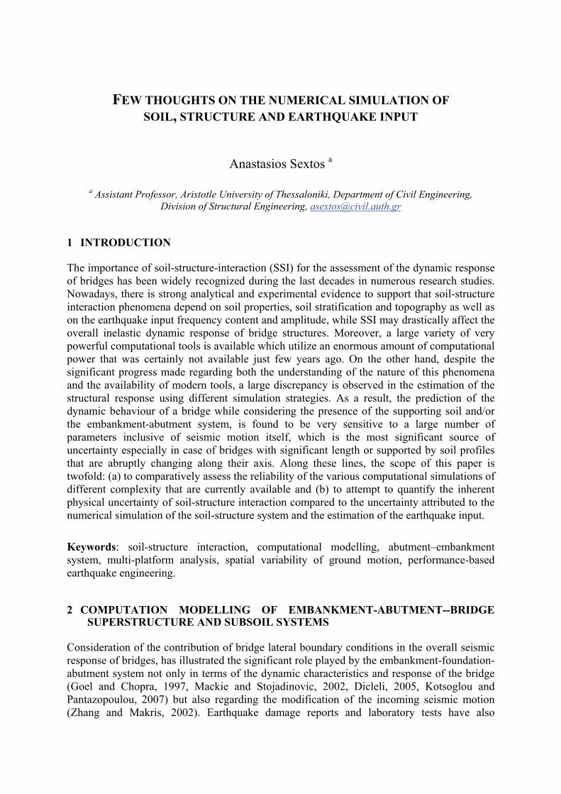
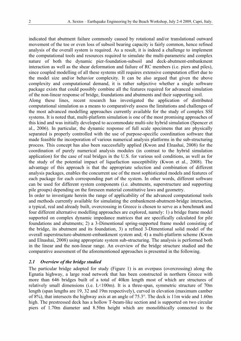
superstructure and the foundation. At the abutments (which have a 10.501.20m wall section of 5.0m height), the deck is connected through two pot bearings that permit sliding along the two principal bridge axes and a sliding joint separates the deck from the backwall. Seismic forces are also resisted by the activation of stoppers (in the transverse direction) which are constructed at the seating of the abutments. The foundation on the other hand is deep, due to the soft clay formations characterizing the overall area. The pier foundation consists of a 22 pile group of 28.0 to 32.0m long piles, connected with a 1.605.05.0m pile cap, while the abutments are supported on a 14 pile row 27 to 35.0m long at 2.80m axial spacing, all piles having equal diameter of 1.0m. The bridge was designed for normal loads according to the German Norms (i.e. DIN 1055, 1045, 1072, 1075, 1054, 4227, 4085, 4014) while the seismic design was carried out according to the Greek Seismic Code EAK 2000 and the relevant Greek standards E39/99 for the seismic design of bridges. The bridge site is located in the Seismic Zone I which is equivalent to a peak ground acceleration of 0.16g. The behaviour factors of the system adopted for design according to the E39/99 document were qx=2.50, qy=3.50 and qz=1.00 for the response in the three principal directions, respectively. The target displacements of the bridge under study for the two directions, the two alternative soil conditions and the two earthquake levels (i.e. design earthquake and twice the design earthquake) are also depicted in Figure 2 (the complete calculation process can be found in Potikas, 2006). It is noted that for twice the design earthquake in the longitudinal direction, the joint is expected to close. Consequently, the overall bridge system stiffness in the longitudinal direction is significantly increased due to the activation of the backfill-abutment-foundation-soil subsystem. It is also noted that in the transverse direction, although damage is indeed minor for the case of soft foundation soil even for displacements corresponding to twice the level of the design earthquake, the abutment piles were found to suffer significant damage due to shear failure at their head when the supporting soil is stiff (Kappos et al., 2007). This situation is apparently detrimental because the abutments can no longer resist their own earth pressure, hence the bridge stability is jeopardized and the high ductility of the middle piers is never utilized. Given the above observations it is clear that for the particular bridge under study, the role played by the abutment is crucial and hence the appropriate modelling of the bridge lateral boundary conditions is necessary.
Figure 1: Longitudinal cross-section of the bridge (above) and indicative overview of a typical
overcrossing along Egnatia Highway (bottom).
A. Sextos – Earthquake Engineering by the Beach Workshop, July 2-4 2009, Capri, Italy.
4
Figure 2: Pushover curve and seismic assessment of the overall system studied in the logitudinal direction
for two different soil categories (after Kappos et al., 2007).
In order to investigate and demonstrate the current capabilities of the various analysis approaches, four different models were developed. The assumptions made in each cases and the performance of all models is summarized in Sextos and Taskari (2008), while a brief description of the overall concept is described in the following:
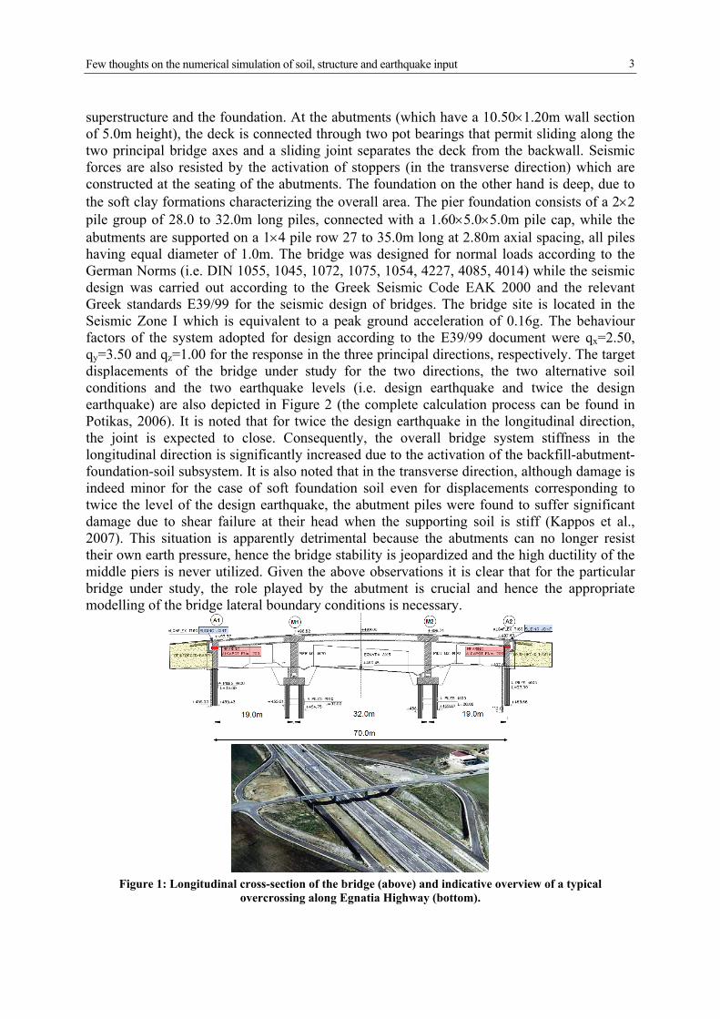
2.2 Frame bridge on Spring and Dashpot systems (Model 1)
First, a bridge frame model supported on complex dynamic impedance matrices that are specifically calculated for pile foundations and abutments is developed. This consists of the superstructure (Figure 3) whose pies are assumed to be connected to 6-DOF spring and dashpot systems with dynamic properties computed using the computer code ASING (Sextos et al., 2003) for coupled translational and rocking modes of vibration and given the foundation and soil properties described in Sextos and Taskari (2008). Pile-to-pile interaction was accounted through the formulation of the particular computer code. The abutment dynamic stiffness and damping is computed according to Zhang and Makris (2002). Kinematic interaction was ignored. The analysis was performed using the widely used FE program Sap2000 and represents the most refined approach that could be expected to be implemented in the design practice.
2.3 Frame bridge on spring supported abutment and foundation (Model 2)
This approach involves the FE model illustrated in Figure 4 inclusive of the superstructure, the abutments as modelled with 2D shell elements in 3D space, as well as the pile foundations modelled using beam-on-dynamic springs. Spring and dashpot values were computed as in Model 1 but distributed based on the area of influence of each particular spring. The analysis was also performed using the FE program Sap2000.
2.4 Frame bridge on 3D solid embankment-foundation-abutment (Model 3)
Bridge superstructure is discretized using 3D frame elements which are then connected to a 3-D (solid) abutment-foundation-embankment system at both lateral supports of the deck (Figures 5 and 6). The piers are assumed to be supported on the 6-DOF dynamic impedance matrices described above while retaining the same properties as previously. Soil was assumed
Few thoughts on the numerical simulation of soil, structure and earthquake input
5
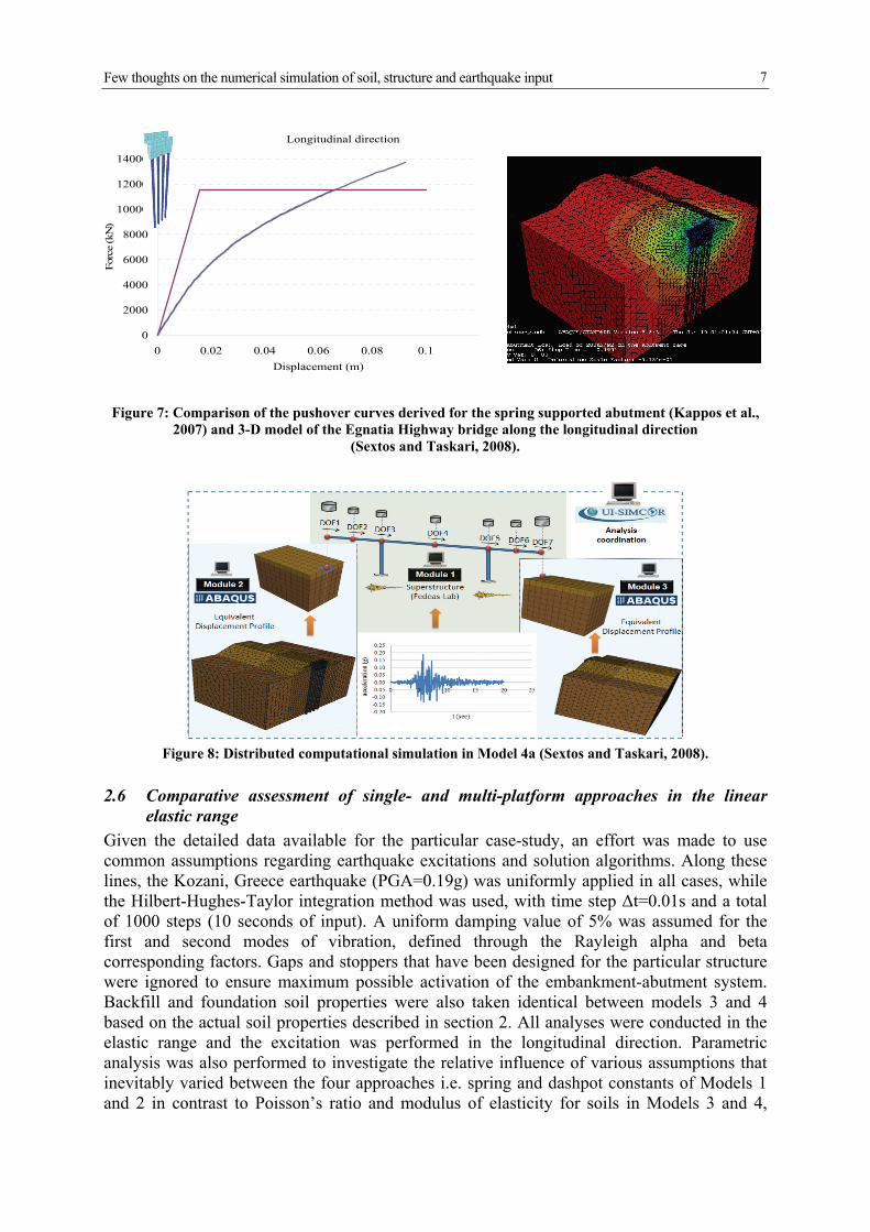
as linear elastic for comparison purposes. The analysis was performed with the advanced FE software Abaqus and the pushover curve for the longitudinal direction is depicted in Figure 7.
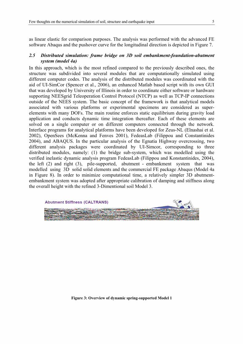
2.5 Distributed simulation: frame bridge on 3D soil embankment-foundation-abutment system (model 4a)
In this approach, which is the most refined compared to the previously described ones, the structure was subdivided into several modules that are computationally simulated using different computer codes. The analysis of the distributed modules was coordinated with the aid of UI-SimCor (Spencer et al., 2006), an enhanced Matlab based script with its own GUI that was developed by University of Illinois in order to coordinate either software or hardware supporting NEESgrid Teleoperation Control Protocol (NTCP) as well as TCP-IP connections outside of the NEES system. The basic concept of the framework is that analytical models associated with various platforms or experimental specimens are considered as super-elements with many DOFs. The main routine enforces static equilibrium during gravity load application and conducts dynamic time integration thereafter. Each of these elements are solved on a single computer or on different computers connected through the network. Interface programs for analytical platforms have been developed for Zeus-NL (Elnashai et al. 2002), OpenSees (McKenna and Fenves 2001), FedeasLab (Filippou and Constantinides 2004), and ABAQUS. In the particular analysis of the Egnatia Highway overcrossing, two different analysis packages were coordinated by UI-Simcor, corresponding to three distributed modules, namely: (1) the bridge sub-system, which was modelled using the verified inelastic dynamic analysis program FedeasLab (Filippou and Konstantinides, 2004), the left (2) and right (3), pile-supported, abutment - embankment system that was modelled using 3D solid solid elements and the commercial FE package Abaqus (Model 4a in Figure 8). In order to minimize computational time, a relatively simpler 3D abutment-embankment system was adopted after appropriate calibration of damping and stiffness along the overall height with the refined 3-Dimentional soil Model 3.
Figure 3: Overview of dynamic spring-supported Model 1

A. Sextos – Earthquake Engineering by the Beach Workshop, July 2-4 2009, Capri, Italy.
6
Figure 4: Overview of dynamic spring-supported Model 2
Figure 5: Overview of the 3-Dimentional Model 3
Figure 6: Plastic strains developed due to non-linear static (pushover) analysis of Model 3
Few thoughts on the numerical simulation of soil, structure and earthquake input
7
Figure 7: Comparison of the pushover curves derived for the spring supported abutment (Kappos et al., 2007) and 3-D model of the Egnatia Highway bridge along the longitudinal direction
(Sextos and Taskari, 2008).
Figure 8: Distributed computational simulation in Model 4a (Sextos and Taskari, 2008).
2.6 Comparative assessment of single- and multi-platform approaches in the linear elastic range
Given the detailed data available for the particular case-study, an effort was made to use common assumptions regarding earthquake excitations and solution algorithms. Along these lines, the Kozani, Greece earthquake (PGA=0.19g) was uniformly applied in all cases, while the Hilbert-Hughes-Taylor integration method was used, with time step Δt=0.01s and a total of 1000 steps (10 seconds of input). A uniform damping value of 5% was assumed for the first and second modes of vibration, defined through the Rayleigh alpha and beta corresponding factors. Gaps and stoppers that have been designed for the particular structure were ignored to ensure maximum possible activation of the embankment-abutment system. Backfill and foundation soil properties were also taken identical between models 3 and 4 based on the actual soil properties described in section 2. All analyses were conducted in the elastic range and the excitation was performed in the longitudinal direction. Parametric analysis was also performed to investigate the relative influence of various assumptions that inevitably varied between the four approaches i.e. spring and dashpot constants of Models 1 and 2 in contrast to Poisson’s ratio and modulus of elasticity for soils in Models 3 and 4,
Longitudinal direction
0
2000
4000
6000
8000
10000
12000
14000
0 0.02 0.04 0.06 0.08 0.1
Displacement (m)
Forc
e (k
N)
A. Sextos – Earthquake Engineering by the Beach Workshop, July 2-4 2009, Capri, Italy.
8
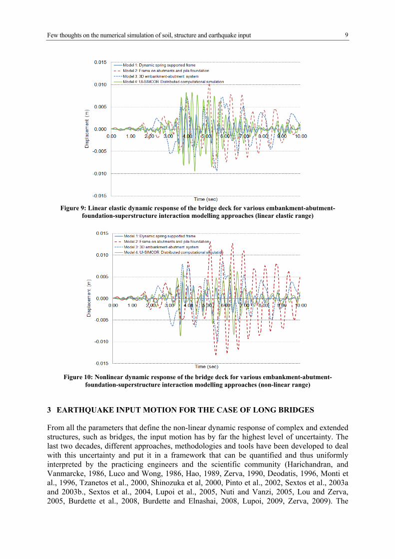
embankment finite element mesh dimensions and size, among many others. It was concluded that the parameter related to the maximum level of uncertainty was the critical embankment mass that was expected to be activated during the particular earthquake excitation and most importantly, the means to simulate its effect in the framework of the four different analysis strategies adopted. In contrast to the validation case (section 4) the value of the single point mass that was used for Models 1 and 2 at the lateral boundaries of the bridge to represent the ‘active’ embankment-abutment system, was predicted independently (blindly) based on the concept of critical embankment length (Zhang and Makris, 2002) and without any calibration to 3-D solid Models 3 and 4, where the activated embankment mass was inherently considered. Next, the dispersion in the dynamic response of the bridge due to the assumptions and modelling approach adopted is illustrated in Figure 9. In particular, it is seen that following four different approaches to consider the effect of embankment-abutment-superstructure interaction, the maximum longitudinal displacement of the deck lies in the range of 0.6-1.0cm whereas the fundamental period of the overall system may also differ by more than 100% despite the effort to use compatible properties where available. Further response measures (i.e. middle pier stresses) are not presented herein due to lack of available space; however, it is noted that the dispersion is of the same order. It is also seen (Sextos and Taskari, 2008) that multi-platform analysis is a very promising concept since it provides stable results within the envelope of the response produced by the other three approaches while enabling the consideration of 3-Dimentional geometry without exceeding the computational time required for a conventional single-platform 3-D modelling of the entire embankment-abutment-bridge system.
2.7 Comparative assessment of single- and multi-platform approaches in the nonlinear range
Following the assessment of the four different approaches examined in the linear range, an effort was made to compare the response of the bridge in the non-linear range. The dynamic impedance matrices of Model 1 which represent the abutment-embankment as well as the dynamic pile group stiffness were properly modified based on intensity soil properties according to the EC8-Part 5 provisions. The same procedure was applied for the case of the Model 2 through appropriate multi-linear springs and distinct dashpots that were also based on the aforementioned modified soil properties along the pile length. On the other hand, the Mohr-Coulomb constitutive model implemented in Abaqus was utilised to simulate the non-linear soil behaviour in the case of the, more refined Model 3. As for the model 4, secant stiffness based on the detailed pushover analysis results along the longitudinal direction (Figure 7) was applied within the framework of an equivalent linear analysis. It is noted that the lateral assumption is not introducing any additional uncertainty to the problem since it essentially introduces an ‘exact’ (i.e., derived through refined pushover analysis) non-linear, force-displacement relationship at each abutment control point that is used thorugh a multi-platform process that is also inherently pseudo-static. The dispersion of the results is presented in the Figure 10 where it is seen that multi-platform analysis is not only feasible in the non-linear range, but it leads to comparable results with those derived with more conventional approaches both in terms of longitudinal displacement amplitude of the deck and of the fundamental period increase of the system as a whole. Moreover, it is noted that the multi-platform simulation coordinated by UI-Simcor, may also have significant advantages regarding for capturing the inelastic response of the R/C piers, as it can combine a number of specialised constitutive models and software currently available.
Few thoughts on the numerical simulation of soil, structure and earthquake input
9
Figure 9: Linear elastic dynamic response of the bridge deck for various embankment-abutment-
foundation-superstructure interaction modelling approaches (linear elastic range)
Figure 10: Nonlinear dynamic response of the bridge deck for various embankment-abutment-
foundation-superstructure interaction modelling approaches (non-linear range)
3 EARTHQUAKE INPUT MOTION FOR THE CASE OF LONG BRIDGES
From all the parameters that define the non-linear dynamic response of complex and extended structures, such as bridges, the input motion has by far the highest level of uncertainty. The last two decades, different approaches, methodologies and tools have been developed to deal with this uncertainty and put it in a framework that can be quantified and thus uniformly interpreted by the practicing engineers and the scientific community (Harichandran, and Vanmarcke, 1986, Luco and Wong, 1986, Hao, 1989, Zerva, 1990, Deodatis, 1996, Monti et al., 1996, Tzanetos et al., 2000, Shinozuka et al, 2000, Pinto et al., 2002, Sextos et al., 2003a and 2003b., Sextos et al., 2004, Lupoi et al., 2005, Nuti and Vanzi, 2005, Lou and Zerva, 2005, Burdette et al., 2008, Burdette and Elnashai, 2008, Lupoi, 2009, Zerva, 2009). The
A. Sextos – Earthquake Engineering by the Beach Workshop, July 2-4 2009, Capri, Italy.
10
extensive work on predicting or producing refined response spectra as well as the large data of actual ground motions recorded on different soil and seismotechtonic conditions that are currently available are a precious source of information that has allowed a better understanding of both the characteristics of seismic motion and its implications on the earthquake performance of such structures. Additionally, the increasingly enhanced capabilities now available for inelastic dynamic analysis provide a very good estimate of their expected response under earthquake loading. Nevertheless, it is not obvious that all this progress in developing seismic hazard scenarios, predicting suitable seismic motions and performing advanced numerical analyses of the superstructure is indeed reflected to the overall design reliability of a system, since the uncertainty of the inherent hypothesis made that a (long) structure is uniformly excited with an identical (natural or artificial) earthquake motion cannot be easily justified. It is true that the critical question is not whether seismic motion is indeed different along an extended structure; this is almost self-evident, physically justified and the sources of spatial and temporal variations of seismic motion have been well identified (Der Kiureghian and Keshishian, 1997) as: a) waves that travel at a finite velocity, so that their arrival at each support point is out of phase b) wave coherency loss in terms of gradual reduction of their statistical dependence with distance and frequency, due to multiple reflections, refractions and superpositioning during propagation and c) local site effects. As a result of all the above sources, both peak ground acceleration and frequency content of the motion may be significantly different among the various foundation points. Moreover, although often neglected, the potential filtering at the foundation level that results from the relative flexibility of the foundation-soil system components, is an additional source of seismic motion variability (Sextos et al., 2003a). In addition to the above theoretical justification, Spatial Variability of Earthquake Ground Motion (SVEGM) has also been recorded in various densely instrumented arrays all over the world (SMART-1 and LSST-Lotung in Taiwan, Chiba in Tokyo, USGS-Parkfield and Imperial Valley in California, as well as Euroseis-Test in Greece among others), hence the fact that a long structure is expected to be excited with asynchronous and partially uncorrelated seismic forces is evident and well documented. The main question therefore, is how the designer may produce ‘reasonable’ spatially varying suites of ground motion, what the response of a structure would be under such an asynchronous excitation, whether the final response is detrimental compared to the prediction made assuming a structure uniformly excited in the time domain, and especially whether it can be indeed predictable in advance during the design process. The answer to this question is difficult not only due to the complexity in predicting incoherency patterns but also, due to the significant coupling between earthquake input, dynamic characteristics of the soil-structure system (particularly in terms of foundation compliance and energy dissipation) at the soil-foundation interface. What follows is therefore an effort to investigate the above phenomena with emphasis on numerous bridge structures studied. The methodology was also applied for the case of extended Byzantine city Walls (Stylianidis and Sextos, 2009) as a means to examine more general trends of the effect of asynchronous excitation to large structures that are not limited by the typical bridge configurations and structural systems. The overall methodology developed for the study of the particular problem is described in detail immediately after and the results from the study of the 27 bridges studied are presented in a macroscopic, qualitative way in order to permit drawing of more general conclusions. The section concludes with some general observations and recommendations as regard to the assessment and design of extended structures.
Few thoughts on the numerical simulation of soil, structure and earthquake input
11
3.1 Overview of the parametric analysis scheme
The spatially variable earthquake input has been generated for various combinations and scenarios using the computer code ASING (Sextos et al., 2003b). With the aid of this software, which is based on the methodology presented by Sextos et al. (2003a), 27 bridges (including 5 actual, already built, structures) that present many different structural characteristics were studied and analysed with the assumptions described in Table 1; they were subjected to a large number (271) of spatially variable earthquake ground motion scenarios as presented in detail elsewhere (Sextos and Kappos, 2008). For all the bridges studied a uniform excitation analysis (base excitations assumed identical) was performed as a reference level hence the influence of spatial variability was expressed in terms of the SVEGM-effect ratio:
excitation ssynchronoufor in timemoment bendingor nt displaceme maximum
excitation usasynchronofor in timemoment bendingor nt displaceme maximum (1)
For each of the 271 cases, 3 or 5 realizations of the input motion have been generated and the average value of ρ was obtained. It is herein recognised that ideally, a Monte Carlo scheme should have been applied, however, the large number of structures studied and the phenomena simultaneously considered (i.e., spatial variability, soil-structure interaction, site effects) render such an approach essentially prohibitive. It is also noted that the 27 bridges studied have been initially excited with records compatible with different target earthquake motion as an effort to quantify the importance of the ground motion frequency content in the light of considering the effect of spatial variability. Therefore in order to account for both the above issues, for all cases studied, the effect of spatial variability is expressed solely in relative terms, that is, using the ratio of eq. (1), and no conclusions are drawn based on absolute terms. Moreover, aiming to additionally evaluate the new EC8 provisions, an additional set of analyses has been performed using the Eurocode 8 design spectrum corresponding to a peak ground acceleration equal to 0.24g, ground type B and a behaviour factor q=1 as the common reference frequency content for all bridges specifically studied. The spatially varying ground motion time-histories have equal duration of 20 sec, and reflect an identical prescribed coherence function. In particular, the widely used Loco and Wong (1986) loss of coherency pattern was adopted, assuming moderate coherency drop (i.e. parameter α was set to 2.510-4 sec/m) while the apparent propagation velocity Vapp was set equal to 1000 m/sec.
3.2 Impact of analysis and design assumptions
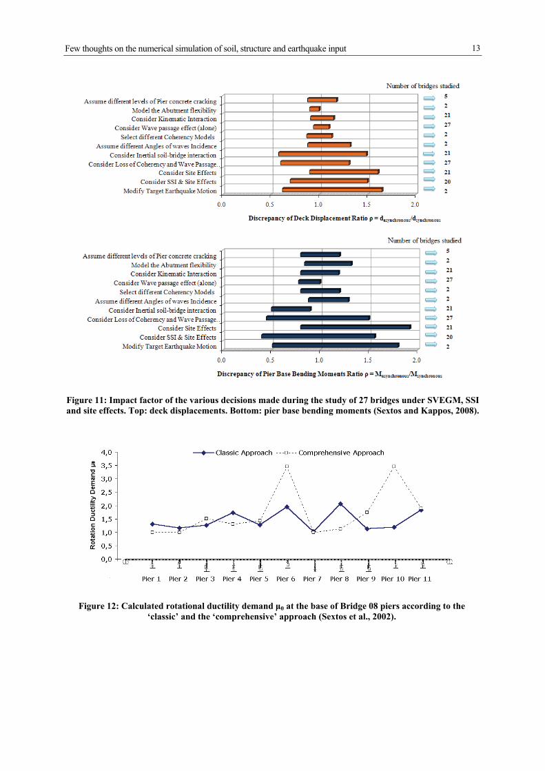
Based on the analyses of the 27 bridges briefly presented in Table 2, an effort was made to identify and quantify the parameters of SVEGM analysis that have the maximum impact on the action effects, with focus on two critical response quantities, deck displacements and pier bending moments. In Figure 11, the variation of the average value of ρ (eq. 1) due to various analysis and modelling assumptions is illustrated. In brief, for each specific assumption or decision regarding the consideration (or not) of a particular phenomenon (for example, kinematic or inertial interaction, site effects, different frequency content, or direction in which the excitation is applied), SVEGM analysis was performed and deck displacements and pier-base bending moments were computed and compared with the ones derived through synchronous excitation dynamic analysis. The ratios ρ were thus calculated for each pier of each particular bridge for which the specific analysis assumption was ‘switched on and off’. As a result, each bridge is characterised by a maximum and a minimum value of ρ due to the
A. Sextos – Earthquake Engineering by the Beach Workshop, July 2-4 2009, Capri, Italy.
12
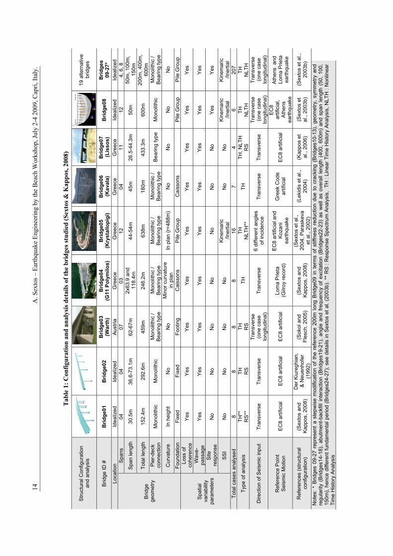
specific decision that was made during the SGEVM analysis. Next, the mean value of the maximum ρ values among all bridges, plus one standard deviation (μ+σ) and the mean value of the minimum ρ value among all bridges minus one standard deviation (μ-σ) are derived and plotted in Figure 11 to represent the variation of the impact of each decision in terms of pier base bending moments and deck displacements. As previously, it has to be stressed that processing statistically sets of data resulting from such different cases both in terms of structural characteristics and analysis complexity is an inevitably subjective effort, especially given the fact that the study of the potential importance of each decision made is based on samples of unequal size (there are some parameters whose effect has been studied for two bridges only). Therefore, the illustration of Figure 11 can only be interpreted as a rough, qualitative indication of the tendencies observed in a problem for which enough and completely consistent data could only be gathered with great difficulty (and they are not currently available). As an effort, therefore, to take advantage of the wide variety of the bridge configurations studied and given the above significant limitations, three very general comments can be possibly made: First, it seems that accounting during the design process for local site response, multiple reference (target) earthquake motions, coherency loss, and the coupling between soil-structure interaction and site effects, has an impact on the accuracy of the procedure for tackling SVEGM effects, which is higher than that of the variation of the parameters assumed for the coherency models to be used, the abutment flexibility, or the stiffness of concrete members (the corresponding range of variation of the value of ρ is significantly smaller in the latter cases). In other words, it seems that errors resulting from completely neglecting significant physical phenomena during the analysis are higher than those due to improper selection of the parameters involved in the description of these phenomena; furthermore, uncertainty in these parameters could be tackled through parametric analysis. This observation is also reflected on Figure 12 where the calculated rotational ductility demand μθ at the base of Bridge 08 piers according to the ‘classic’ and the ‘comprehensive’ approach is presented (Sextos et al., 2002). It is seen that by considering spatial variability, soil structure interaction and local site response phenomena the ductility demand is modified significantly at almost all piers, compared to the ‘classic’ approach where all the above phenomena are ignored, even for fixed values for the coherency models used and the stiffness of abutments, piers and piles. Secondly, it could be claimed that consideration of spatial variability alone may be proven inadequate, independently of the method used, if a reliable estimate of the target earthquake characteristics and foundation flexibility is not obtained in advance. Finally, a tendency is observed that (as expected) stresses are more sensitive to the decisions made than displacements, a fact that is important for the design process. In any case, ignoring spatial variability of earthquake ground motion does not necessarily lead to conservative design since the ratio of ρ can be higher than unity for a large number of scenarios studied. Moreover, by plotting the SVEGM-effect ratio ρ with the overall length of each bridge (Sextos and Kappos, 2008) it is seen that the above findings are in agreement with the more conservative limits introduced in Eurocode 8. Based on the analyses results of the dynamic response of 27 (real and idealised) bridges under synchronous and asynchronous excitation, an effort was made to quantify the relative importance of the various parameters involved on the on the action effects (deck displacements and bending moments) of the superstructure. Given the complexity of the problem and the infinite combinations of bridge dynamic characteristics, seismotectonic environment, and ground conditions, it is very difficult to derive general design or analysis rules to account for spatial variation of ground motion that can be used without any exception.
Few thoughts on the numerical simulation of soil, structure and earthquake input
13
Figure 11: Impact factor of the various decisions made during the study of 27 bridges under SVEGM, SSI and site effects. Top: deck displacements. Bottom: pier base bending moments (Sextos and Kappos, 2008).
Figure 12: Calculated rotational ductility demand μθ at the base of Bridge 08 piers according to the ‘classic’ and the ‘comprehensive’ approach (Sextos et al., 2002).
A
. Sex
tos
– E
arth
quak
e E
ngin
eeri
ng b
y th
e B
each
Wor
ksho
p, J
uly
2-4
2009
, Cap
ri, I
taly
.
14
Tab
le 1
: C
onfi
gura
tion
an
d an
alys
is d
etai
ls o
f th
e b
rid
ges
stud
ied
(S
exto
s &
Kap
pos
, 200
8)
Stru
ctur
al C
onfig
urat
ion
and
anal
ysis
19 a
ltern
ativ
e br
idge
s
Brid
ge ID
#
Bri
dg
e01
B
rid
ge0
2
Bri
dg
e03
(W
arth
) B
rid
ge0
4
(G11
Po
lym
ilos
) B
rid
ge0
5 (K
ryst
allo
pig
i)
Bri
dg
e06
(Ka
vala
) B
rid
ge0
7 (L
iss
os)
B
rid
ge0
8
Bri
dg
es
09-2
7*
Loca
tion
Idea
lized
Id
ealiz
ed
Aus
tria
Gre
ece
Gre
ece
Gre
ece
Gre
ece
Idea
lized
Id
ealiz
ed
Brid
ge
geom
etry
Spa
ns
04
04
07
03
12
04
11
12
4, 6
, 8
Spa
n le
ngth
30
.5m
36
.6-7
3.1m
62
-67m
2x
63.9
and
11
8.4m
44
-54m
45
m
26.5
-44.
3m
50m
50
m, 1
00m
, 15
0m
Tota
l len
gth
152.
4m
292.
6m
459m
24
6.2m
63
8m
180m
43
3.3m
60
0m
200m
, 400
m,
600m
P
ier-
deck
co
nnec
tion
Mon
olith
ic
Mon
olith
ic
Mon
olith
ic /
Bea
ring
type
M
onol
ithic
/ B
earin
g ty
pe
Mon
olith
ic /
Bea
ring
type
M
onol
ithic
/ B
earin
g ty
pe
Bea
ring
type
M
onol
ithic
M
onol
ithic
/ B
earin
g ty
pe
Cur
vatu
re
In h
eigh
t N
o N
o M
inor
cur
vatu
re
in
pla
n In
pla
n (r
=488
m)
No
No
No
No
Foun
datio
n Fi
xed
Fixe
d Fo
otin
g C
aiss
ons
Pile
Gro
up
Cai
sson
s
Pile
Gro
up
Pile
Gro
up
Spa
tial
varia
bilit
y pa
ram
eter
s
Loss
of
cohe
renc
e Ye
s Ye
s Ye
s Ye
s Ye
s Ye
s Ye
s Ye
s Ye
s
Wav
e-pa
ssag
e Ye
s Ye
s Ye
s Ye
s Ye
s Ye
s Ye
s Ye
s Ye
s
Site
re
spon
se
No
No
No
No
No
No
No
Yes
Yes
SS
I N
o N
o N
o N
o K
inem
aric
/In
ertia
l N
o N
o K
inem
aric
/In
ertia
l K
inem
aric
/In
ertia
l To
tal c
ases
ana
lyse
d 8
8 8
8 16
7
4 6
207
Type
of a
naly
sis
TH**
R
S**
TH
R
S
TH
RS
TH
TH
N
LTH
**
TH
TH, N
LTH
R
S
TH
NLT
H
TH
NLT
H
Dire
ctio
n of
Sei
smic
inpu
t Tr
ansv
erse
Tr
ansv
erse
Tr
ansv
erse
(o
ne c
ase
long
itudi
nal)
Tran
sver
se
6 di
ffere
nt a
ngle
s of
inci
denc
e Tr
ansv
erse
Tr
ansv
erse
Tr
ansv
erse
(o
ne c
ase
long
itudi
nal)
Tran
sver
se
(o
ne c
ase
long
itudi
nal)
Ref
eren
ce P
oint
S
eism
ic M
otio
n E
C8
artif
icia
l E
C8
artif
icia
l E
C8
artif
icia
l Lo
ma
Prie
ta
(Gilr
oy re
cord
)
EC
8 ar
tific
ial a
nd
Koz
ani
earth
quak
e
Gre
ek C
ode
artif
icia
l E
C8
artif
icia
l
EC
8 ar
tific
ial,
Ath
ens
earth
quak
e
Ath
ens
and
Lo
ma
Prie
ta
earth
quak
e
Ref
eren
ces
(stru
ctur
al
conf
igur
atio
n)
(Sex
tos
and
Kap
pos,
200
8)
Der
Kiu
regh
ian,
&
Neu
enho
fer
(199
2)
(Sok
ol a
nd
Fles
ch, 2
005)
(S
exto
s an
d K
appo
s, 2
008)
(Sex
tos
et a
l.,
2004
, Par
aske
va
et a
l., 2
002)
(Lek
idis
et a
l.,
2004
) (K
appo
s et
al
., 20
06)
(Sex
tos
et
al.,
2003
b)
(Sex
tos
et a
l.,
2003
b)
Not
es:
* B
ridge
s 09
-27
repr
esen
t a
step
wis
e m
odifi
catio
n of
the
ref
eren
ce 2
00m
long
Brid
ge09
in t
erm
s of
stif
fnes
s re
duct
ion
due
to c
rack
ing
(Brid
ges1
0-13
), ge
omet
ry,
sym
met
ry a
nd
regu
larit
y (B
ridge
s14-
18),
abut
men
t-bac
kfill
inte
ract
ion
(Brid
ges1
9-21
), an
gle
and
frequ
ency
of e
xcita
tion
(Brid
ges2
2-23
) as
wel
l as
over
all l
engt
h (4
00, 6
00m
) an
d sp
an le
ngth
(50
, 10
0,
150m
), he
nce
diffe
rent
fund
amen
tal p
erio
d (B
ridge
s24-
27);
see
deta
ils in
Sex
tos
et a
l. (2
003b
). **
RS
: R
espo
nse
Spe
ctru
m A
naly
sis,
TH
: Li
near
Tim
e H
isto
ry A
naly
sis,
NLT
H :
Non
linea
r Ti
me
His
tory
Ana
lysi
s
Nevertheless, the results presented herein lead to the conclusion that ignoring spatial variability of earthquake ground motion does not necessarily lead to conservative design since its effect can be very often detrimental at least for overall bridge length that exceeds the newly set (more conservative) limits introduced in Eurocode 8. The above observations were also verified for the case of a long and straight circuit of the Byzantine Walls of the city of Thessaloniki (Stylianidis and Sextos, 2008), a fact that additionally highlights the necessity to study the particular problem for other kinds of extended structures as well (i.e. pipelines, tunnels, dams). However, despite the significant research effort on the physical modelling of the problem, it is deemed that the present state-of-the-art has to be enriched with additional analytical and experimental results, focusing on the study of the response of a larger number of real structures. This effort can be also supported by utilizing the growing number of available recorded data within the ground and on the ground surface and, even more importantly, on the foundation and the superstructure.
4 ACKNOWLEDGEMENTS
This work was been accomplished with the valuable contribution of various colleagues which are not reported as co-authors herein due to the nature of the particular workshop but their contribution is evident in the reference list below. Apart from that, the author would like to thank Prof. A. Kappos and P. Potikas at Aristotle University Thessaloniki for kindly providing all the data and results derived during the non-linear static assessment of the bridge studied. It is also notable that most of the results reported herein have been obtained within the framework of the Research Project ‘Seismic Protection of Bridges’ (ASProGe) funded by the General Secreteriat of Research and Technology, of Greece (2004-2007) in collaboration with the scientific responsible Professor Andreas Kappos. Acknowledgements are also due to Prof. Amr Elnashai and Assist. Prof. Oh-Sung Kwon for their precious assistance regarding the application of the analysis coordinator UI-Simcor, developed at the University of Illinois, as well as the Earthquake Engineering Research Center (EERC) at University California Berkeley and Prof. B. Stojadinovic for their overall support during the first author’s visit in the framework of which part of this work was conducted. The contribution of Professor Kosmas Stylianidis as regard to the investigation of the dynamic response of monumental structures under asynchronous excitation is also equally appreciated.
5 REFERENCES
Burdette, N. and Elnashai, A.S. (2008) “The effect of asynchronous earthquake motion on complex bridges. Part 1: Results and Implications on Assessment”, Journal of Bridge Engineering, 13(2): 166-172.
Burdette, N., Elnashai, A.S., Lupoi, A. and Sextos, A. (2008) “The effect of asynchronous earthquake motion on complex bridges. Part 1: Methodology and Input Motion”, Journal of Bridge Engineering, 13(2): 158-165.
CEN (2004) Eurocode 8: Design of Structures for Earthquake Resistance-Part 1: General Rules, seismic action and rules for buildings, EN 1998-1:2004, European Committee of Standardisation.
Deodatis G. (1996) “Simulation of ergodic multi-variate stochastic processes”, Journal of Engineering Mechanics, 122(8): 778-787.
Der Kiureghian, A. and A. Neuenhofer (1992) “Response Spectrum method for multiple support excitations”, Earthquake Engineering and Structural Dynamics, 21: 713-740.
A. Sextos – Earthquake Engineering by the Beach Workshop, July 2-4 2009, Capri, Italy.
16
Der Kiureghian, A. and Keshishian (1997) “Effects of incoherence, wave passage and spatially varying site conditions on bridge response”, FHWA/NCEER Workshop on the National Representation of Seismic Motion, Report 97-0010, NY, 393–407.
Dicleli, M. (2005) “Integral Abutment-Backfill Behavior on Sand Soil—Pushover Analysis Approach”, Journal of Bridge Engineering, 10(3): 354-364.
Elnashai, A. S., Papanikolaou, V., and Lee, D. (2002) “Zeus NL – A System for Inelastic Analysis of Structures”, Mid-America Earthquake Center, Univ. of Illinois at Urbana-Champaign.
Filippou, F. C., and Constantinides, M. (2004) “FEDEASLab Getting Started Guide and Simulation Examples”, Technical Report NEESgrid-2004-22: www.nees-grid.org
Goel, R.K., and Chopra, A. (1997) “Evaluation of bridge abutment capacity and stiffness during earthquakes”, Earthquake Spectra, 13(1): 1-23.
Hao H. (1989) “Effects of spatial variation of ground motions on large multiply-supported structures”, UBC/EERC-89/06, Berkeley: EERC, University of California.
Harichandran, R.S. and Vanmarcke, E. H. (1986) “Stochastic variation of earthquake ground motion in space and time”, Journal of Engineering Mechanical Division, 112: 154-174.
Kappos, A., Potikas, P. and Sextos, A. (2007) “Seismic assessment of an overpass bridge accounting for non-linear material and soil response and varying boundary conditions”, Computational Methods in Structural Dynamics and Earthquake Engineering, COMPDYN, Rethymnon, Greece, CD-ROM Volume.
Kappos, A.J., Moschonas, I.F., Paraskeva, Th. and Sextos, A.G. (2006) “A methodology for derivation of seismic fragility curves for bridges with the aid of advanced analysis tools”, 13th ECEE, Geneva, Paper no. 275.
Kotsoglou, A. and Pantazopoulou, S. (2007) “Bridge–embankment interaction under transverse ground excitation”, Earthquake Engineering and Structural Dynamics, 36:1719–1740.
Kwon, O. S. and Elnashai, A. S. (2008) “Seismic Analysis of Meloland Road Overcrossing Using Multiplatform Simulation Software Including SSI”, Journal of Structural Engineering, 134(4): 651-660.
Kwon, O.S., Sextos, A. and Elnashai, A. (2008) “Liquefaction-dependent fragility relationships of complex bridge-foundation-soil systems”, International Conference on Earthquake Engineering and Disaster Mitigation, Jakarta, Indonesia, 14-15 April.
Lekidis, V. , Karakostas, C., Christodoulou, K. , Karamanos, S., Papadimitriou, K. Panetsos, P. (2004) “Investigation of dynamic response and model updating of instrumented R/C bridges”, 13th World Conference on Earthquake Engineering, Vancouver, Canada, Paper No. 2591.
Lou, L., and Zerva, A. (2005)” Effects of spatially variable ground motions on the seismic response of a skewed, multi-span, RC highway bridge”, Soil Dynamics and Earthquake Engineering, 25(7-10): 729-740.
Luco, J.E. and Wong, H.L. (1986) “Response of a rigid foundation to a spatially random ground motion”, Earthquake Engineering and Structural Dynamics, 4: 891-908.
Lupoi, A., Franchin, P., Pinto, P. E., and Monti, G. (2005) “Seismic design of bridges accounting for spatial variability of ground motion”, Earthquake Engineering and Structural Dynamics, 34(4-5): 327-348.
Lupoi, A. (2009) “The Response of Isolated Bridges Accounting for Spatial Variability of Ground Motion”, Journal of Earthquake Engineering, no. 13: 814-834.
Mackie, K., and Stojadinovic, B. (2002) “Bridge Abutment Model Sensitivity for Probabilistic Seismic demand evaluation”, Proceedings of The 3rd National Seismic Conference & Workshop on Bridges & Highways, April 28-May 1, Portland.
Few thoughts on the numerical simulation of soil, structure and earthquake input
17
McKenna, F., and Fenves, G. L. (2001) The OpenSees command language manual, version 1.2., Pacific Earthquake Engineering Research Center, Univ. of California at Berkeley.
Ministry of Environment, Physical Planning, and Public Works (1999) Circular 39/99: Guidelines for the Seismic Design of Bridges, Athens (in Greek).
Ministry of Public Works (2000). Greek Seismic Code—EAK 2000, Athens (amended 2003, in Greek).
Monti G., Nuti C. and Pinto P.E. (1996) “Nonlinear response of bridges under multi-support excitation”, Journal of Structural Engineering, 122(10): 1147-1159.
Nuti, C. and Vanzi, I. (2005) “Influence of earthquake spatial variability on differential soil displacements and SDF system response”, Earthquake Engineering and Structural Dynamics, 34(11): 1353–1374.
Paraskeva, T., Kappos, A. and Sextos, A. (2002) “Extension of modal pushover analysis to seismic assessment of bridges”, Earthquake Engineering and Structural Dynamics, 35: 1269–1293.
Pinto, A., Pegon, P. Magonette, and Tsionis, G. (2002) “Pseudo-dynamic testing of bridges using non-linear substructuring”, Earthquake Engineering and Structural Dynamics, 33(11): 1125 – 1146.
Potikas, P. (2006) Seismic Design and Assessment of an Overpass Bridge, MSc Thesis, Aristotle University Thessaloniki, Greece (in Greek).
Sextos, A., Kappos, A. and K. Pitilakis (2002) “Effect of analysis complexity on the calculated ductility demand of RC bridges”, 12th European Conference on Earthquake Engineering, London, U.K., 7-13 September, CD-RΟΜ Volume, paper 653, 2002.
Sextos, A., Pitilakis, K. and Kappos, A. (2003a) “Inelastic dynamic analysis of RC bridges accounting for spatial variability of ground motion, site effects and soil-structure interaction phenomena. Part 1: Methodology and analytical tools”, Earthquake Engineering and Structural Dynamics, 32(4): 607-629.
Sextos A., Kappos A. and Pitilakis K. (2003b) Inelastic dynamic analysis of RC bridges accounting for spatial variability of ground motion, site effects and soil-structure interaction phenomena. Part 2: Parametric study”, Earthquake Engineering and Structural Dynamics, 32(4): 629-652.
Sextos, A., Kappos, A. and Mergos P. (2004) “Effect of Soil-Structure Interaction and Spatial Variability of Ground Motion on Irregular Bridges: The Case of the Krystallopigi Bridge”, 13th World Conference on Earthquake Engineering, Vancouver, Canada, Paper No. 2298.
Sextos, A. and Kappos, A. (2008) “Seismic response of bridges under asynchronous excitation and comparison with EC8 design rules”, Bulletin of Earthquake Engineering Engineering, 7, 519-545.
Sextos, A., Mackie, K., Stojadinovic, B and Taskari, O. (2008) “Simplified P-y relationships for modelling embankment-abutment systems of typical California bridges”, 14th Word Conference on Earthquake Engineering, Beijing, China, CD-ROM Volume.
Shinozuka M, Saxena V and Deodatis, G. (2000) “Effect of Spatial Variation of Ground Motion on Highway Structures”, MCEER-00-0013, MCEER, NY.
Sokol, M. and Flesch, R. (2005) “Assessment of Soil Stiffness Properties by Dynamic Tests on Bridges”, Journal of Bridge Engineering, 10(1): 77-86.
Spencer Jr., B. F., Elnashai, A. S., Park, K., and Kwon, O. (2006) “Hybrid Test Using UI-SimCor, Three-Site Experiment”, Final report to NEESit for Phase I project of hybrid simulation framework development, University of Illinois at Urbana-Champain.
Stylianidis, K. and Sextos, A. (2009) “Back analysis of Thessaloniki Byzantine Land Walls as a means to assess its Seismic History”, International Journal of Architectural Heritage, 3(4): 1-23.

A. Sextos – Earthquake Engineering by the Beach Workshop, July 2-4 2009, Capri, Italy.
18
Tzanetos N., Elnashai A. S., Hamdan F. H., Antoniou S. (2000) “Inelastic Dynamic Response of RC Bridges Subjected to Spatial Non-Synchronous Earthquake Motion”, Advances in Structural Engineering, 3(3): 191-214.
Zerva, A. (1990) “Response of multi-span beams to spatially incoherent seismic ground motions”, Earthquake Engineering and Structural Dynamics, 19(6): 819-832.
Zerva, A. (2009) Spatial Variation of Seismic Ground Motions: Modeling and Engineering Applications (Advances in Engineering Series). Ed. Haym Beranoya. CRC Press, Taylor & Francis Group, FL.
Zhang, J., and Makris, N. (2002) “Kinematic response functions and dynamic stiffness of bridge embankments”, Earthquake Engineering and Structural Dynamics, 31: 1933–1966.


![Anastasios Taliotis: Un. Of Crete, CCTP Elias Kiritsis and Anastasios Taliotis Arxiv:[1111.1931]](https://img.pdfslide.us/doc/110x75/5697bfdc1a28abf838cb11db/anastasios-taliotis-un-of-crete-cctp-elias-kiritsis-and-anastasios-taliotis.jpg)