Embed Size (px)
Citation preview
Analyzing the forces within unilateral transtibial prosthetic sockets and design of an improved force minimizing socket
Christine Bronikowski, Amanda Chen, Jared Mulford, Amy Ostrowski
Advisor: Aaron Fitzsimmons, The Surgical Clinic
Problem Statement
•Lack of research in the socket interface between the artificial limb and the residual limb, specifically force profiles▫Majority of research based on models with historically
proven success and qualitative assessments
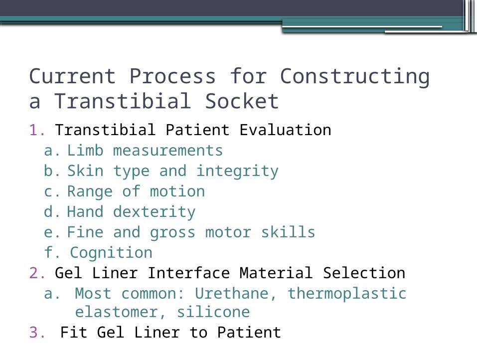
Current Process for Constructing a Transtibial Socket1. Transtibial Patient Evaluation
a. Limb measurementsb. Skin type and integrityc. Range of motiond. Hand dexteritye. Fine and gross motor skillsf. Cognition
2. Gel Liner Interface Material Selectiona. Most common: Urethane, thermoplastic
elastomer, silicone3. Fit Gel Liner to Patient
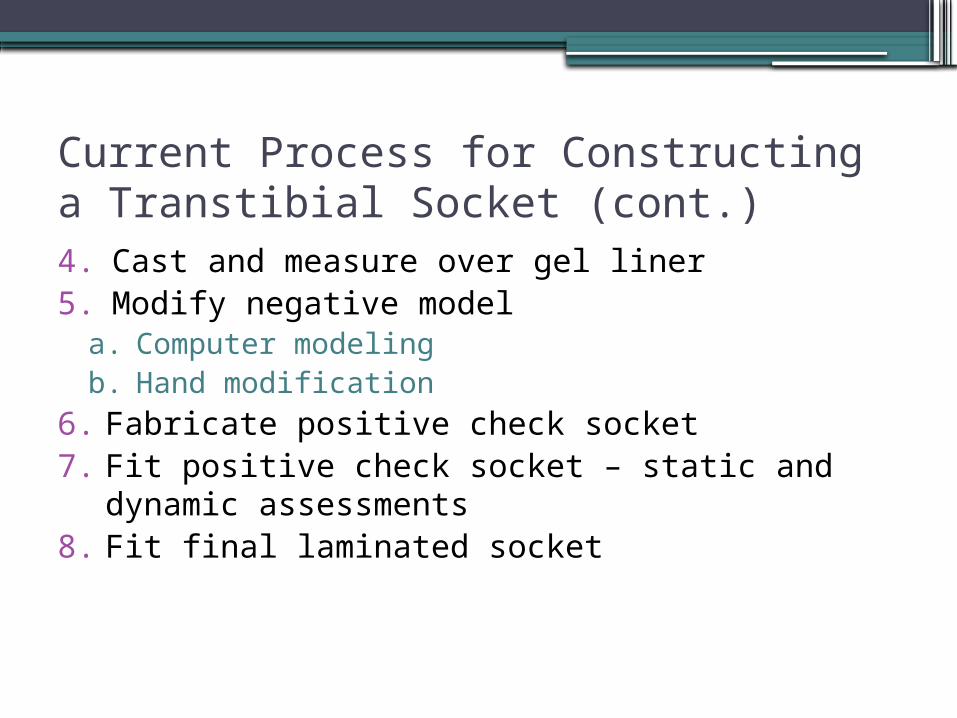
Current Process for Constructing a Transtibial Socket (cont.)4. Cast and measure over gel liner5. Modify negative model
a. Computer modelingb. Hand modification
6. Fabricate positive check socket7. Fit positive check socket – static and dynamic
assessments8. Fit final laminated socket
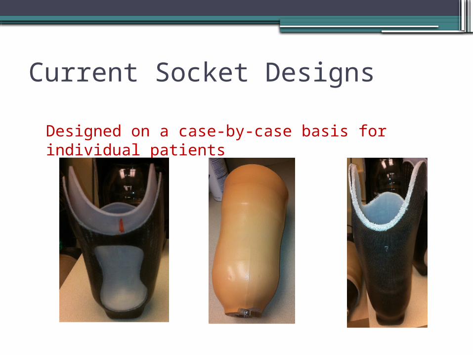
Current Socket Designs
Designed on a case-by-case basis for individual patients
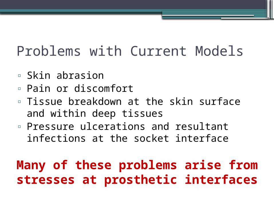
Problems with Current Models▫ Skin abrasion▫ Pain or discomfort▫ Tissue breakdown at the skin surface and
within deep tissues▫ Pressure ulcerations and resultant infections
at the socket interface
Many of these problems arise from stresses at prosthetic interfaces
Project Goals
•Acquire accurate measurements of perpendicular forces acting on the residual limb of transtibial amputee during various movements
•Pinpoint regions with highest forces•Design a socket system in which forces are optimally
distributed throughout the residual limb-socket interface
• Increase overall patient comfort
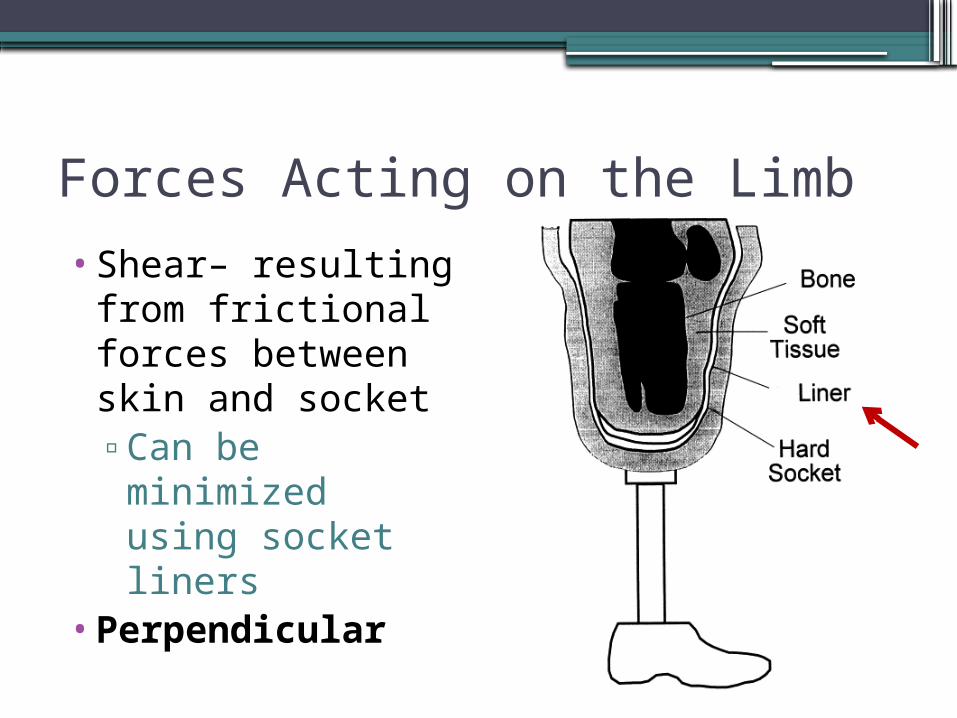
Forces Acting on the Limb
•Shear– resulting from frictional forces between skin and socket▫Can be
minimized using socket liners
•Perpendicular
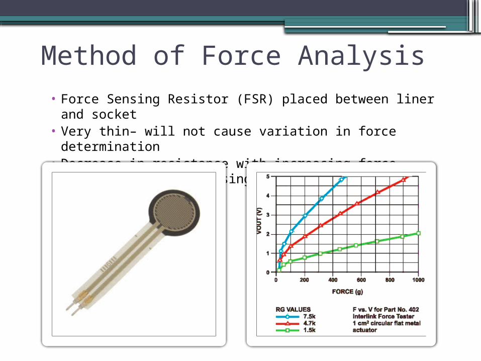
Method of Force Analysis• Force Sensing Resistor (FSR) placed between liner and
socket• Very thin– will not cause variation in force determination• Decrease in resistance with increasing force, which leads
to increasing output voltage
Placement of FSRs
•Impractical to cover every area of the residual limb with sensors
•One FSR used in each area of clinical interest (i.e. areas expected to face larger pressures and cause patient discomfort)
• Patellar Tendon • Anterodistal Area
• Medial Tibia
• Lateral Tibia
• Popliteal Depression

Data Acquision
Circuit design: current to voltage converter
QuickTime™ and aTIFF (Uncompressed) decompressor
are needed to see this picture.
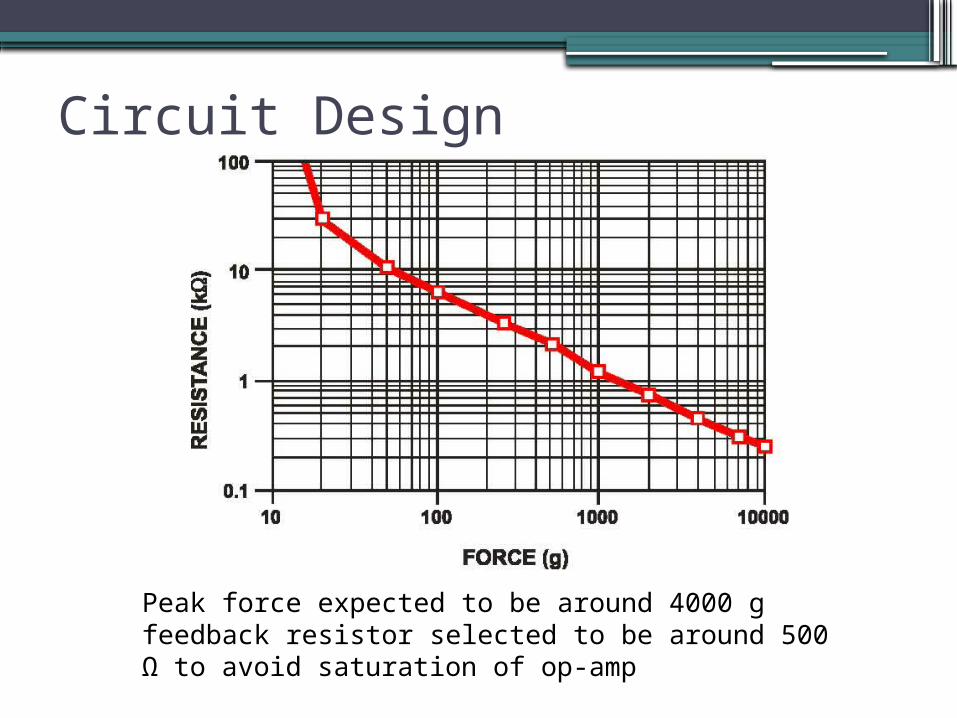
Circuit Design
Peak force expected to be around 4000 g feedback resistor selected to be around 500 Ω to avoid saturation of op-amp
Current Status
•Compact RIO (analog-to-digital converter) connection with computer set up
•FSRs connected to measuring circuit•1/21/2011 – First trial at The Surgical
Clinic with Cody, a transtibial amputee patient▫Test if circuit reaches saturation▫Check sensor sensitivity – changes in
resistance that are too rapid with changes in force undesirable
Design/Safety Considerations
•Wire thickness▫Thin enough to prevent interference with force
data▫Thick enough to remain durable during
movement •FSR-wire connection
▫Cannot break during movement
Future Work
• Successful first trial construct more systems for more patients (~10)▫Rotate FSRs within socket to cover entire
area▫Test multiple surfaces (incline, flat, stairs)
• Analyze results, determine regions containing peak forces
• Use different types of sockets on Cody• Design and develop new socket: provide more
cushioning in areas of greatest force
Determination of Success
•Design is patient-driven•Measure forces before and after fitting of
new socket and compare values
ReferencesEngsberg, J.R., Springer, M.J.N., and J.A. Harder. (1992). Quantifying interface
pressures in below-knee-amputee sockets. J Assoc Child Prosthet Orthot Clin 27(3), 81-88.
Houston, V. L., Mason, C.P., LaBlanc, K.P., Beattie, A.C., Garbarini, M.A., and E.J.
Lorenze. Prelimary results with the DVA-Tekscan BK prosthetics socket: residual limb stress measurement system. In: Proceedings fo the 20th Annual Meeting American Academy of Orthotist and Prosthetist, Nashville TN. P 8-9
Jendrzejczyk, D. J. (1985). Flexible Socket Systems. Clin. Prosthet. Orthot. 9 (4), 27-31. Lee, W.C., and M. Zhang. Using computational simulation to aid in the prediction of
socket fit: a preliminary study. Med Eng Phys. 2007 Oct;29(8):923-9. Polliack, A.A., Sieh, R.C., Craig, D.D., Landsberger, S., Mcneil, D.R., and E. Ayyappa.
Scientific validation of two commercial pressure sensor systems for prosthetic socket fit. Prosthetics and Orthotics International, 2000, 24, 63-73.
Sanders, J.E., Daly, C.H., and E.M. Burgess (1993). Clinical measurement of normal
shear stresses on a transtibial stump: Characteristics of wave-form shapes during walking. Prosthet Orthot Int 17, 38-48.