Embed Size (px)
Citation preview

Finite Element Analysis of a Transtibial
prosthetic during Gait Cycle
Faiz M. Rohjoni1, Mohd Nor Azmi Ab Patar
1,3*, Jamaluddin Mahmud
1, Hokyoo Lee
2, Akihiko Hanafusa
3
1 Faculty of Mechanical Engineering, Universiti Teknologi MARA, Shah Alam, Selangor, Malaysia
2 Department of Mechanical and Control Engineering, Niigata Institute of Technology, Japan
3 Department of Bio-science and Engineering, Shibaura Institute of Technology, Japan
Email: *[email protected]
Abstract— Prosthesis is an artificial part used by amputees
as an alternative device to support activities of daily life. It is
used to replace the amputated limb and mimic the human
movement and locomotion. This paper aims to analyze the
stress distribution of a transtibial prosthetic leg during gait
cycle using CATIA V5. The dimension of the prototype was
based on an average dimension of an actual human foot of
Malaysian. The prototype implemented the integration of
mechanical and electrical components. Furthermore, the
movement of the prototype are based on deviations of angle
between pylon and foot. The deviations were detected by
rotary angle sensor which then triggered the DC motor to
operate. Static analysis had been done using Generative
Structural Analysis workbench in CATIA V5 software.
Peak von Mises stress were found on the foot at toe off. The
highest von Mises stress at the pylon beam was 995MPa and
has stress of 156MPa on top of the pylon during heel strike.
Furthermore, the foot has peak stress up to 3.18MPa. The
result presented here may facilitate improvement of cost-
effective prosthetic leg.
Index Terms— active prosthetic leg, static simulation;
transtibial prosthetic leg, prosthetic model, 3D prosthetic
I. INTRODUCTION
Prosthesis is an artificial component used to replace
the missing limb that caused by injury or accident. The
development of the prosthesis has started long way before
the Dark Ages. During that time, most of the patient who
lost their limb wanted to feel whole and complete again
so that they can make their daily routine as usually. The
growth of inventors of the prosthetic leg are enhanced by
the World War I and World War II. During that time,
there are many injuries sustained and the number of
amputees is increasing rapidly. It opens the opportunities
for experimentation and development of new type of
prosthesis that can give more advantages to the user [1].
Numerous societies and organizations were formed to
support the prosthetist and their innovation.
Prosthesis help the amputees to feel normal. After
losing their limb, their daily routines change entirely. The
amputee pace is slower and the stability is lesser
compared to the non-amputee [2]. It makes it harder for
them to move freely and they need to rely on wheelchair
Manuscript received June 21, 2019; revised March 7, 2020.
or walking stick to help them move from one place to
another. There is a desire to feel whole and complete
again. It is important that prosthesis satisfy this need as
the advancement of the technology are moving rapidly
from time to time. Samuel [3] proposed that active
prosthetic leg can provide more natural gait rather a
conventional passive prosthesis. The bionic prosthetic leg
developed have flourish all over the world as a device
that can mimic perfectly almost the human gait cycle.
This is because human movement is complicated
behavior involves the integration of nervous system that
will result in motor action [4]. Active prosthetic leg can
help a person to walk at better metabolic rate and energy
consumption compared to the passive prosthetic leg as
proposed by Herr [5]. It is supported by Margaret [6] who
proposed that patient who use passive prosthetic leg will
have their normal gait impaired which result in various
risk such as risk of falling down and physiological
pathologies. Moreover, Eilenberg [7] also found that
normal and fast walking speed require more external
energy and passive prosthetic leg cannot be used for this
intention as it will only be a good approximation of
ankle’s function only during slow walking. The users
wearing the conventional prosthesis will also walk slower
as they need more metabolic energy as proposed by
Eilenberg [8]. Although the growth of the better
prosthetic legs is increasing, it is an expensive and many
people cannot afford the technology [9,10,11]. To address
the issue, many developers have designed the prosthetic
devices that can be fabricated locally at low cost.
This paper presents to analyze the stress distribution of
a transtibial prosthetic leg during gait cycle. There are
two types of simulation that have been done to the
prototype. The first one is finite element analysis for
static simulation. Then, the other simulation is DMU
Kinematic simulation using the same software, CATIA
V5. This simulation advantage to determine the
theoretical speed and acceleration of the prototype during
the gait cycle [12, 13, 14] after completed assembled. The
properties and the specification of the prototype has been
developed to be similar as the previous literature with
added value of cost-effective material [15, 16]. Then, the
results obtained have been compared to the selected
journal which related to the scope of preliminary studies.
764
International Journal of Mechanical Engineering and Robotics Research Vol. 9, No. 5, May 2020
© 2020 Int. J. Mech. Eng. Rob. Resdoi: 10.18178/ijmerr.9.5.764-770

II. METHODOLOGY
A. Design Methodology
The scope of the preliminary studies focused on the
development of an innovative mechanism for transtibial
prosthesis and simulated the mechanical behavior using
CATIA V5 software. In finite element analysis (FEA),
the prosthetic socket was not included due to the
complexity of the design. This study has been divided
into different phases as illustrated in Fig. 1. For
geometries configuration of the foot, it was made by the
improvement of the previous study using reverse
engineering techniques. The prototype dimension based
on the average dimension of an actual human foot of
Malaysian. The material used for the simulation was
Polylactic Acid (PLA) plastic. The material characteristic
revealed in Table III. After the FEA analysis was
accomplished and the result was obtained. Then, the
fabrication of the prototype was visualized using 3D
printer where the filament consuming the same material
as the simulation conducted. All the components that has
been printed were assembled and integrated with
electrical components. Then, the functionality of the
system tested manually for its modification.
Figure 1. Flow chart for the modification method of active transtibial
prosthetic leg
B. Geometries
The prosthetic leg has been developed into three
segment including foot, pylon and ankle. The
specifications of each segments are exposed in Table I.
All of the segments are connected to each other using
shaft and screws. The lower leg and foot are connected
together through shaft whereas the ankle is connected to
the foot using screws. Fig. 2 demonstrates the prototype
model that has been modelled in CATIA V5. The 3D
CAD software also be used for modeling mechanical
parts. The vertical load and clamp location have been
selected at the crucial parts for static simulation while the
kinematic simulation has been composed with motions
equations for speed and acceleration. The 3D model has
been developed are represented by rigid body shape to
replicate the human leg and foot. The initial position of
the rigid body has been set and connected to each other
by shaft and screws. The foot has been connected to the
pylon using shaft and acted as fulcrum point for the pylon
to move forward and backward.
Meanwhile, the ankle and the foot were connected
together using screws. Each connector for parts sets as
revolute axis to simulate the movements needed. The
kinematic data was tracked using joints sensor during gait
cycle.
Figure 2. Completed assembled parts of transtibial prosthetic leg in CATIA V5
C. Design Specification
Table I shows the dimensions of the component that
has been fabricated using in house low-cost 3D printer
(Creality Ender 3 Pro). The dimensions selected are based
on literature review and has been modified to fit the
specification of the 3D printer.
TABLE I. MODEL SPECIFICATION
Components Parameters Dimensions (mm)
Foot
Length 300
Width 128
Thickness 10
Pylon
Height 235
Width 100
Diameter 10
Ankle
Length 200
Width 100
Thickness 10
The cost-effective transtibial prosthetic leg based on
the best available design has been selected as a
benchmark and the specification of the components has
been recorded. The proposed components as listed in
Table II has similar specification of established an active
transtibial prosthetic leg nevertheless cheaper and easy to
obtain in local market.
765
International Journal of Mechanical Engineering and Robotics Research Vol. 9, No. 5, May 2020
© 2020 Int. J. Mech. Eng. Rob. Res
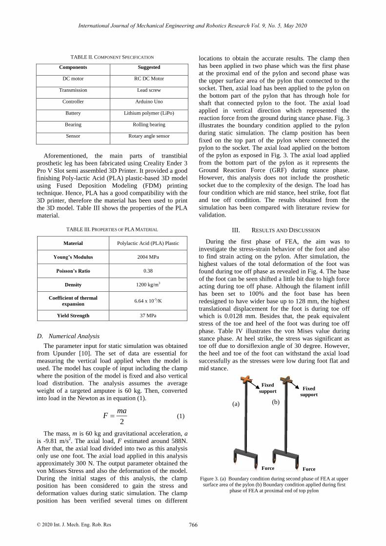
TABLE II. COMPONENT SPECIFICATION
Components Suggested
DC motor RC DC Motor
Transmission Lead screw
Controller Arduino Uno
Battery Lithium polymer (LiPo)
Bearing Rolling bearing
Sensor Rotary angle sensor
Aforementioned, the main parts of transtibial
prosthetic leg has been fabricated using Creality Ender 3
Pro V Slot semi assembled 3D Printer. It provided a good
finishing Poly-lactic Acid (PLA) plastic-based 3D model
using Fused Deposition Modeling (FDM) printing
technique. Hence, PLA has a good compatibility with the
3D printer, therefore the material has been used to print
the 3D model. Table III shows the properties of the PLA
material.
TABLE III. PROPERTIES OF PLA MATERIAL
Material Polylactic Acid (PLA) Plastic
Young’s Modulus 2004 MPa
Poisson’s Ratio 0.38
Density 1200 kg/m3
Coefficient of thermal
expansion 6.64 x 10⁻⁵/K
Yield Strength 37 MPa
D. Numerical Analysis
The parameter input for static simulation was obtained
from Upunder [10]. The set of data are essential for
measuring the vertical load applied when the model is
used. The model has couple of input including the clamp
where the position of the model is fixed and also vertical
load distribution. The analysis assumes the average
weight of a targeted amputee is 60 kg. Then, converted
into load in the Newton as in equation (1).
2
maF (1)
The mass, m is 60 kg and gravitational acceleration, a
is -9.81 m/s2. The axial load, F estimated around 588N.
After that, the axial load divided into two as this analysis
only use one foot. The axial load applied in this analysis
approximately 300 N. The output parameter obtained the
von Misses Stress and also the deformation of the model.
During the initial stages of this analysis, the clamp
position has been considered to gain the stress and
deformation values during static simulation. The clamp
position has been verified several times on different
locations to obtain the accurate results. The clamp then
has been applied in two phase which was the first phase
at the proximal end of the pylon and second phase was
the upper surface area of the pylon that connected to the
socket. Then, axial load has been applied to the pylon on
the bottom part of the pylon that has through hole for
shaft that connected pylon to the foot. The axial load
applied in vertical direction which represented the
reaction force from the ground during stance phase. Fig. 3
illustrates the boundary condition applied to the pylon
during static simulation. The clamp position has been
fixed on the top part of the pylon where connected the
pylon to the socket. The axial load applied on the bottom
of the pylon as exposed in Fig. 3. The axial load applied
from the bottom part of the pylon as it represents the
Ground Reaction Force (GRF) during stance phase.
However, this analysis does not include the prosthetic
socket due to the complexity of the design. The load has
four condition which are mid stance, heel strike, foot flat
and toe off condition. The results obtained from the
simulation has been compared with literature review for
validation.
III. RESULTS AND DISCUSSION
During the first phase of FEA, the aim was to
investigate the stress-strain behavior of the foot and also
to find strain acting on the pylon. After simulation, the
highest values of the total deformation of the foot was
found during toe off phase as revealed in Fig. 4. The base
of the foot can be seen shifted a little bit due to high force
acting during toe off phase. Although the filament infill
has been set to 100% and the foot base has been
redesigned to have wider base up to 128 mm, the highest
translational displacement for the foot is during toe off
which is 0.0128 mm. Besides that, the peak equivalent
stress of the toe and heel of the foot was during toe off
phase. Table IV illustrates the von Mises value during
stance phase. At heel strike, the stress was significant as
toe off due to dorsiflexion angle of 30 degree. However,
the heel and toe of the foot can withstand the axial load
successfully as the stresses were low during foot flat and
mid stance.
Figure 3. (a) Boundary condition during second phase of FEA at upper
surface area of the pylon (b) Boundary condition applied during first
phase of FEA at proximal end of top pylon
(a) (b)
Fixed
support Fixed
support
Force Force
766
International Journal of Mechanical Engineering and Robotics Research Vol. 9, No. 5, May 2020
© 2020 Int. J. Mech. Eng. Rob. Res

Figure 4. Deformation of foot at toe off condition
TABLE IV. PEAK VON MISES STRESS ON THE HEEL AND TOE SPRING AT LOADING CONDITION
Load condition Heel strike Foot flat Mid stance Toe off
Von Mises stress (MPa) Toe 0.00103 5.4x10⁻⁷ 1.08x10⁻⁶ 0.0099
Heel 0.00286 0.00107 0.00151 0.0523
TABLE V. PEAK VON MISES STRESS IN SEVERAL AREAS ON THE PYLON
Load Condition Peak von Mises stress in areas
(MPa)
1 2 3 4 5 6
Mid Stance 9.27 12 12 12 12 27.9
Heel strike 742 538 423 263 214 114
Toe off 359 295 225 157 995 591
Foot flat 5.31 6 6 6 6.29 19.1
Besides that, as shown in Table V, its summaries the
value of peak von Mises stresses in different area on the
pylon as illustrated in Fig. 6. Due to the bending load on
the pylon during simulation, the pylon has slight
deflection. The highest von Mises stress at the pylon
during simulation is at heel strike. This is due to
compressive load and dorsiflexion angle of 30 degrees.
More-over, the components of this model are mostly
stressed during toe off. Fig. 6 illustrates the view of von
Mises stress distribution in the pylon that connect it to the
pylon with the areas of peak stress areas marked. Table
VI shows the values for the peak von Mises stress on top
of the pylon in three different areas. Furthermore, small
diameter of pylon increases the force due to small surface
area. The diameter of the pylon is just 10 mm; thus, the
stress is high on the pylon. The value of von Mises stress
tends to decrease throughout the peak area to illustrate
that the prototype is need to modify to get better
mechanism to withstand the load applied. The lower the
von Mises stress the better the mechanism.
Figure 5. Area of peak von Mises stress on top of the pylon
767
International Journal of Mechanical Engineering and Robotics Research Vol. 9, No. 5, May 2020
© 2020 Int. J. Mech. Eng. Rob. Res

Figure 6. Areas of peak von Mises stress on the pylon
TABLE VI. PEAK VON MISES STRESS ON TOP OF THE PYLON
Load Condition Peak von Mises stress in areas
(MPa)
1 2 3
Mid Stance 4.91 2.88 2.59
Heel strike 156 44.3 57.2
Toe off 70.8 22.7 28.5
Foot flat 2.48 1.44 1.35
Fig. 5 demonstrates the stresses on top of the pylon.
The top of the pylon was set as boundary condition on the
proximal end of it and also the entire surface on the top.
This boundary condition was set as it represents the
connection between the pylon and the socket as the
socket was not included in FEA. The highest von Mises
stress was at heel strike. The peak von Mises stress was
156 MPa. It demonstrated that the top of the pylon needs
better improvement in term of the mechanism and
dimension. However, during mid stance, the top of the
pylon has the smallest stress compared to another stance
phase. The results illustrated that the pylon also has high
von Mises stress at the top of the pylon at toe off. As
mentioned before, foot of the model has peak stress also
at toe off.
IV. RECOMMENDATIONS AND FUTURE WORKS
The new model that has been developed was based on
previous study. It was an improvement from the literature
reviews. The prototype can be improved by increasing
the diameter of the pylon. By increasing the diameter, it
can improve the strength of the pylon and lower the von
Mises stress through-out the pylon. Besides that, the
ankle needs to be redesigned subsequently the DC motor
can turn the screw transmission more smoothly and
increase the percentage to actually mimic the gait cycle.
The current ankle design of the model has small diameter
and gave high friction to the lead screw. High friction
will increase the rotational speed produced by the DC
motor. Moreover, the lead screw can be flattened at one
end. The flattened area can be connected to the DC motor
using coupling and lower the friction with the ankle.
Furthermore, the prototype should be printed using 3D
printer using 80 to 100% of density infill. This will verify
that the prototype has enough thickness. Thus, the test for
its functionality can be conducted. DC motor need
enough voltage in order to have the desired torque and
power. Battery should be at least 12 V or use lithium
polymer (LiPo) battery as secondary choice. This project
can be studied further on the simulation works. In future,
SimMechanics soft-ware will be used in kinematic
simulation to analyze systems behavior as it will give
better results. Furthermore, for static simulation, we
should use better software to implement the Finite
Element Analysis. ABAQUS or ANSYS software can be
used for static simulation to obtain accurate data for
further analysis. Thus, this research also needs better
pylon mechanism to withstand the average weight of
person. The modification will make our prototype more
assurance in term of structural strength and more energy
efficient in the cost effective an active transtibial
prosthetic leg.
V. CONCLUSIONS
The results when the load applied in the four
conditions are shown as table above. At heel strike
768
International Journal of Mechanical Engineering and Robotics Research Vol. 9, No. 5, May 2020
© 2020 Int. J. Mech. Eng. Rob. Res
condition, the pylon has several critical points where the
Von Misses stress is high. This critical point where Von
Misses stress is highest cause deformation on the pylon.
The diameter of the pylon is just 1cm or 10mm only. That
is why the deformation happen and the Von Misses stress
is high. Although the top of the pylon at the connectors
were deformed, but it has low Von Misses stress. The
stress from the top of the pylon passes through the pylon
itself to the bottom of pylon and that is where most of the
compressive stress stored and cause the high Von Misses
stress. It is critical to lower the stress to prevent the pylon
to have bigger deformation. This project use Poly-lactic
Acid (PLA) plastic as material and has properties as
shown in Table III. The model needs to be redesign to
have better results in FEA. The model needs to have
better diameter at the pylon. Small diameter of pylon will
cause high stress due to small surface area. By increasing
the diameter of pylon, the model can have better results
in FEA. The bottom part of the pylon that connect pylon
to the foot also need to be bigger in term of its size. It
will make sure that the pylon can have suitable and
bigger part as its base. Although the value of stress on
pylon is high, it will only cause deflection of 0.958 mm.
Other than that, this study has used 3D printer to fabricate
the prototype. The prototype has only 30% of density
infill. The part that has been printed by using the printer
is ankle, foot and pylon. The prototype needs to be
printed from 80-100% of density infill so that it will have
greater strength and thickness to be used as prosthetic leg.
The printer has not enough space to print all the
component on 1:1 scale. Two parts have been
compromised in term of the size. The foot and pylon have
been scaled down a little
CONFLICT OF INTEREST
The authors declare no conflict of interest.
AUTHOR CONTRIBUTIONS
Mohd Nor Azmi Ab Patar and Faiz M. Rohjoni,
conceived of the presented idea. Jamaluddin Mahmud
developed the theoretical framework and Faiz M. Rohjoni
performed the numerical simulations. Hokyoo Lee
contributed to the interpretation of the results and
Akihiko Hanafusa verified the analytical methods. Mohd
Nor Azmi Ab Patar encouraged Faiz M. Rohjoni to
investigate finite element analysis of a transtibial
prosthetic during gait cycle and supervised the findings of
this work. All authors discussed the results and
contributed to the final manuscript.
ACKNOWLEDGMENT
This research was supported by rehabilitation research
group. We are thankful to our colleagues who provided
expertise that greatly assisted the research. We are also
grateful to Munir Safian for assistance with designing and
programming electrical circuit. We are also immensely
grateful to FYP2 panels for their comments on an earlier
version of the manuscript, although any errors are our
own and should not tarnish the reputations of these
esteemed professionals. All authors declare that they have
no conflicts of interest.
REFERENCES
[1] K. Englehart, B. Hudgins, P. A. Parker, “Analysis of a Lower
Limb Prosthesis,” IEEE Transactions on Biomedical Engineering, vol. 48, no. 3, pp. 302–311, 2001.
[2] R. D. Gregg, T. Lenzi, L. J. Hargrove, J. W. Sensinger, “Virtual constraint control of a powered prosthetic leg: From simulation to
experiments with transfemoral amputees,” IEEE Transactions on
Robotics, vol. 30, no. 6, pp. 1455–471., 2014. [3] Z. O. Abu-Faraj, G. F. Harris, P. A. Smith, S. Hassani, “Human
gait and Clinical Movement Analysis,” Wiley Encyclopedia of Electrical and Electronics Engineering, 2015.
[4] H. M. Herr, S. K. Au, “The importance of series and parallel
motor elasticity,” IEEE Robotic & Automation Magazine, 2008.
[5] M. Islam, A. Haque, (2012). Design and development of an EMG
driven microcontroller based prosthetic leg. BangladeshJournal, 4(1). [Online]. Available: https://doi.org/10.3329/bjmp.v4i1.14695
[6] M. Johnstone, Illustrated by Estrid Barton, “Restoration of motor
function in the stroke patient: A physiotherapist’s approach”. Published: Edinburgh; New York; Livingstone, 1987 3rd ed.
[7] M. F. Eilenberg, H. Geyer, H. Herr, “Control of a powered ankle-foot prosthesis based on a neuromuscular model,” in IEEE
Transactions on Neural System and Rehabilitation Engineering,
vol. 18, pp. 164-173, 2010. [8] M. F. Eilenberg, J. Y. Kuan, H. Herr, “Development and
evaluation of a powered artificial gastrocnemius for transtibial amputee gait,” Journal of Robotics, 2018.
[9] S. K. Au, H. Herr, “Initial experimental study on dynamic
interaction between an amputee and a powered ankle-foot prostheses,” in Workshop on Dynamic Walking: Mechanics and
Control of Human and Robot Locomotion, Ann Arbor, May 2006
[10] V. Upender, E. Srikanth, G. Karthik, N. Kumar, “Design modeling
and optimization of a prosthetic runner blade,” vol. 3, pp. 64-70. [11] D. A. Winter, Biomechanics and Motor Control of Fourth Edition,
2009. [12] S. A. Abdelwahab, “Modeling and simulation of lower limb
dynamics using simmechanics for potential applications in
bilateral prosthesis control,” May 2017. [13] M. Omasta and D. Palou, “Medical engineering & physics finite
element analysis for the evaluation of the structural behaviour, of a prosthesis for trans-tibial amputees,” vol. 34, pp. 38–45, 2012.
[14] A. B. Patar MNAB, T. Komeda, J. Mahmud, “Force assisted hand
and finger device for rehabilitation,” In: 2014 International Symposium on Technology Management and Emerging
Technologies. Bandung; 2014.p. 133–8. https://doi:10.1109/ISTMET.2014.6936493.
[15] B. A. Patar, M. N. Azmi, H. Ramli, J. Mahmud, A. H. Yusof,
“Efficacy and safety testing of a new biologically based design
ankle foot orthosis in healthy volunteer,” Applied Mechanics and
Materials, vol. 110, pp. 1953-1957, 2012. [16] M. N. A. A. Patar, T. Komeda, L. C. Yee, and M. Jamaluddin,
“Model-Based Systems Engineering of a Rehabilitation Device,”
Jurnal Teknologi, vol. 76, no. 4, pp. 101-106, 2015.
Copyright © 2020 by the authors. This is an open access article
distributed under the Creative Commons Attribution License (CC BY-
NC-ND 4.0), which permits use, distribution and reproduction in any medium, provided that the article is properly cited, the use is non-
commercial and no modifications or adaptations are made.
Faiz M. Rohjoni born at Johor Bahru on 8th July 1995. He received a Bachelor Degree in
Mechanical Engineering from Universiti
Teknologi MARA (UiTM) Shah Alam on July 2019. His research interests include prosthetic
leg and finite element analysis (FEA).
769
International Journal of Mechanical Engineering and Robotics Research Vol. 9, No. 5, May 2020
© 2020 Int. J. Mech. Eng. Rob. Res

Mohd Nor Azmi Ab. Patar has a Ph.D degree in (Biomechatronic) Engineering, an MSc
(Mechanical) Engineering degree and a B.Eng.
(Hons.) Mechanical Engineering degree from Shibaura Institute of Technology Japan. He
joined the Faculty of Mechanical Engineering UiTM as a lecturer in 2009 and currently as a
Senior Lecturer. Prior to that, he has worked
about one year as an instrument engineer at Rohm Wako Electronic (M) Sdn. Bhd. His
research interests include biomechatronic, mobile robots, assistive technology, rehabilitation engineering, personal mobility, prosthetic &
orthosis, exoskeleton, Artificial Intelligence and Robotics.
Jamaluddin Mahmud has a PhD degree in
(Biomechanical) Engineering from Cardiff University UK, an MSc (Manufacturing)
Engineering degree from International Islamic
University, Malaysia (IIUM) and a B.Eng. (Hons.) Mechanical Engineering degree from
Universiti Teknologi MARA (UiTM). He joined the Faculty of Mechanical Engineering
UiTM as a lecturer in 2001. Prior to that, he has
worked about three as a service engineer at UMW Equipment Sdn. Bhd. Furthermore, due to his expertise and
experience, he sits in many committees, editorial boards, training
groups and evaluating teams in various events at national and international level.
Hokyoo Lee received his Dr. Eng. degree in 2006 from Shibaura Institute of Technology
Graduate School of Engineering, Japan and became an assistant professor faculty of life
design Toyo University. In 2010, he was a
researcher at Hyogo Prefectural the Hyogo Institute of Assistive Technology, Japan. He
now works as an associate professor, Faculty of Engineering, Niigata Institute of Technology.
His current research interests include mechatronics, robotics,
rehabilitation engineering and welfare engineering.
Akihiko Hanafusa received a PhD and master’s and bachelor's degree in engineering
from the University of Tokyo. He became a
lecturer and associate professor at Polytechnic University in 1993. He has been working as a
full-time professor at SIT since 2009. His interests lie in the fields of human welfare, life
support and biomedical engineering.
770
International Journal of Mechanical Engineering and Robotics Research Vol. 9, No. 5, May 2020
© 2020 Int. J. Mech. Eng. Rob. Res