Embed Size (px)
Citation preview

AD-A262 685
MIarch 1993 1/9/84 to 1/9/86
Analytical and Experimenta1 Invest igat ion of Ai~nular Contract V 3b I -8I-(- '(] 7Propulsive Nozzles P.E. 6UI() lV
Pi. I,. 3012TA 1 3
R.R. Conley - McDonnell Douglas Astronautics UL 89J.D. Hoffman, H.D. Thomp_.son, Purdue University
McDonnell Douglas Astro. Co. Purdue UniversitySt. Louis Division West Lafavette IN 47907St. Louis MO 63166
Aero Propulsion and Power DirectorateWright LaboratoryAir Force Materiel Command WL -TR-93-2O:',8Wright-Patterson AFB OH 45433-7655WL/POPR, ATTN: Smith (513) 255-2175
Journal Article
Approved for public release; distribution is unlimitue,.
The final report consists of AIAA papers. The report presents an analyticalperformance prediction methodology for annular propulsion nozzles with and witnoutswirl introduced in the combustor upstream of the nozzle. Four types ofswirlers were investigated: free vortex, constant angle, forced vortex andRankine vortex swirlers. For the no-swirl case thrust efficiencics and staticpressure profiles from cold flow testing of selected nozzles are sum.Iarizedand compared to the predictions.
93-07185
Ramjets, Supersonics 0
Unclassified Unclassified Unci ass if id e
j

NOTICE
WHEN GOVERNMENT DRAWINGS. SPECIFICATIONS. OR OTHER DATA ARE USED FOR ANYPURPOSE OTHER THAN IN CONNECTION WITH A DEFINITELY GOVERNMENT-RELATEOPROCUREMENT. THE UNITED STATES GOVERNMENT INCURS NO RESPONSIBILITY OR ANYOBLIGATION WHATSOEVER. THE FACT THAT THE GOVERNMENT MAY HAVE FORMULATED OR 'N
ANY WAY SUPPLIED THE SAID DRAWINGS. SPECIFICATIONS. OR OTHER DATA. IS NOT TOBE REGARDED BY IMPLICATION. OR OTHERWISE IN ANY MANNER CONSTRUED. AS LICENSINGTHE HOLDER. OR ANY OTHER PERSON OR CORPORATIJN: OR AS CONVEYING ANY RIGHTS ORPERMISSION TO MANUFACTURE. USE. OR SELL ANY PATENTED INVENTION THAT MAY IN ANY
WAY BE RELATED THERETO.
THIS TECHNICAL REPORT HAS BEEN REVIEWED AND IS APPROVED FOR PUBLICATION
J•fiN R. SMITH, Project Engineer WILLIAM C. BURSON, JR., ChiefPropulsion Development Branch Propulsion Development BranchAdvanced Propulsion Division Advanced Propulsion Division
ROBERT E. HENDERSON, ChiefAdvanced Propulsion DivisionAero Propulsion & Power Directorate
IF YOUR ADDRESS HAS CHANGED. IF YOU WISH TO BE REMOVED FROM OUR MAILINGLIST. OR IF THE ADDRESSEE !S NO LONGER EMPLOYED BY YOUR ORGANIZATION PLEASENOTIFY WL/POPR , WRIGHT-PATTERSON AFB. OH 45433- TO HELP MAINTAINA CURRENT MAILING LIST.
COPIES OF THIS REPORT SHOULD NOT BE RETURNED UNLESS RETURN IS REQUIRED BYSECURITY CONSIDERATIONS, CONTRACTUAL OBLIGATIONS. OR NOTICE ON A SPECIFIC
DOCUMENT,

AIAA-84-0282An Analytical and Experimental Investigationof Annular Propulsive NozzlesR.R. Conley, McDonnell Douglas AstronauticsCo., St. Louis, MO; and J.D. Hoffman andH.D. Thompson, Purdue Univ., WestLafayette, IN
93 3 o9 ool
AIAA 22nd Aerospace Sciences MeetingJanuary 9-12, 1984/Reno, Nevada
For permission to copy or republish, contact the American Institute of Aeronautics and Astronautics1633 Broadway, New York, NY 10019

AN ANALYTICAL AND EXPERIMENTAL INVESTIGATIONOF ANNULAR PROPULSIVE NOZZLESA
Ralph R. ConleytMcDonnell Douglas Astronautics Company - St. Louis Division
St. Louis, Missouri 63166
and
Joe 0. Hoffman"t and H. Doyle ThompsontltPurdue University
West Lafayette, Indiana 47907
Abstract Introduction
This paper discusses an analytical performance The conventional propulsive nozzi# • n: an -prediction methodology for annular propulsive noz- symmetric converging-diverging des•in an- has beenzles and tho application of that methodology to used successfully in rocket, turoojet cnd ramietselected nozzles. Thrust efficiencies and static engines for many years. The advantaes spressure profiles from cold flow testing of the nozzles include efficient design-point performance,selected nozzles are summarized and compared to thE reasonable weight and cost and the avaiiabItv opredictions. These comparisons show that the ana- accurate design/analysis techniques. Un thi other
lytical methods are reasonably accurate if the hand, the disadvantages of such nozzles inc!boeradial velocity components in the transorir region excessive length and inetficient cit --diqr por-of annular nozzles are small. The areas ot pre- formance.diction/test disagreement are identified for futureimprovements. Several annular nozzle concepts. ormer t
inserting axisymmnetric centerbodies withn conven-tional nozzles, have been considered to overcomethese disadvantages. As depicted in Figure 1, t'eNomenclature centerbody may be located either upstream. down-stream or in the throat plane of the conventionai
A Area nozzle. The objective of the present work was toASME American Society of Mechanical Engineers conduct analytical and experimental investiqationsCD Discharge Coefficient of selected annular nozzles to acquire a betterIVL Initial Value Line understanding of the flow processes and performancem Mass Flow Rate potential of these concepts.MXC Method of CharacteristicsNPR Nozzle Pressure Ratio This paper presents the re-ilts of this workNTS Nozzle Test Stand for five annular nozzles which encompass the deiqnP Pressure options noted in Figure 1. Primary emphasis is onVNAP Viscous Nozzle Analysis Program an analytical performance prediction meth-doloQvy Ratio of Specific Heats for Such nozz)es and the application of ti-3t metn-n Efficiency odology. The results of considerable cold flowSubscripts testing of selected nozzle models are wilarized anda Ambient compared with the analytical predicS,"ns.act ActualAR Area Ratio All analytical performance -redictions pre-B Base sented in this paper were made r ,Jr to nozzle modeiC Cowl cold flow testing. No revise, bredictions based one Exit pOst-test, "fine tuned" rer,ý,s of the analyticalI Internal codes are included. Therefore, the comparisons with0 Stagnation experimental data show both the strengths and weak-p Centerbody (plug) nesses of the basic prediction methodoloqy. SomePR Pressure Ratio additional capabilities which would enhance theref Reference prediction methodoiory are identified as areas fort Throat future improvemer ,.* Choking
Twas performed under Contract F33615- Cold Flow Testino80-C-2029 with the Aero Propulsion Laboratory, AirForce Wright Aeronautical Laboratories, Wright- Anruaar nozzle model cold flow testina wasPatterson Air Force Base, OH 45433. Mr. J. R. Smith conduc-ed in the McDonnell Aircratt Comnany Nozzleis the Air Force Project Engineer. Test Stand (NTS). The nozzle drvpn v.,ector as-
seroly was used during testinq to obtain performancet Technical Specialist, Member AIAA (ata at higher pressure ratios. A brief descriptiontt Professor of Mechanical Engineering of the NTS and ejector assembly are presented inMpimipr ATAA this section.
ttt Professor of Mechanical EngineeringAssociate Fellow AIAA
Co"wdghw (ý Anqtockis luaitsute of A~anatilks sodAstmemutics. fee.. t99U. All rights rmarved,

BEAY LINEAR VARIABLEJ,-~~ ~ BEA8 ',-•-m
S) FFERE1RNTIAL TRANSFORMER 'LvDi.
F LOVV, .0%
NOZZLE TEST STAL
PENOULUM, ARM
"(ONE OF rWO \
CENTER)IVDY UPSTREAV UST NOZZLE
6 FEET EJECTOR ASSEMBLY
,SONIC
FLLON
NOZZLE AIRPLENUM GAP
SEAL
Fig. Nozzle test stand.
The thrust measurement accuracy of the NTS fornozzies exhausting into the atmosphere I e. ., with-
Out the ejector) were verified by tests with an
American Society of Mechanical Engineers (ASME)standard nozzle. These nozzles are conmmonly used toverify thrust measurement facilities since thethrust efficiency is easily calculated with one-
LOY LoNEc dimensional theory. As shown in Figure , a curvefit of data from a typical verification test serieswith the ASME nozzle is approximately 0.4 percentbelow the theoretical line. This excellent corre-lation confirms the accuracy of the NTS thrustmeasurement method.
CENTERBODY IN THROAT
Fig. 1 Annular nozzle concepts. ASME STANOARDO NOZZLE
ATMOSPHERc EXHAUST
The NTS, depicted in Figure 2, was developed to 98 R
provide precise measurements of nozzle thrust andflow rate. Test nozzles are attached to a plenum 96 %AvERAGEDIFFERENCE
assembly which is mounted between the arms of adouble armed pendulum. Pressure regulated, dry airis supplied to the plenum by dual supply lines which 9
run parallel to the pendulum arms. Thus, theincoming air is perpendicular to the nozzle thrust 92axis and its momentum does not influence the thrust ONE DIMENSIONAL THEORYmeasurement.
An ejector assembly, also depicted in Figure 2,is used with the NTS to increase nozzle pressure 0
ratio (plenum pressure/back pressure) capability.The exhaust flow from the test nozzle drives theejector and lowers the nozzle back pressure below r LEASTSOUARESCURVEFITthe ambient pressure.
Nozzle model thrust during testing is measured 0 ,8 20 24 ,8 3. iS
by recording the deflection of the pendulum about NOZZL PRIESSURE RATIO
the I-beam flexure with a linear variable differ-ential transformer (LVDT). The thrust magnitude is Fig. 3 NTS thrust measurement evaluationdetermined by miltiplying the deflection distance summary.by the deflection constant which is determined priorto each test series using dead weight loading with a Thrust measurement capability of the NTS withpulley arrangement. The air supply lines are the ejector was verified by comparing nozzle etfi-pressurized during the calibration process. Thus. ciency data between runs exhaustinQ into the atmo-tare forces due to thrust and pressure loads are sphere and runs exhausting into the ejector. Suchincluded in the calibration data. comparisons for a conical nozzle are oresented In
2

Figure 4 and show excellent agreement between the .rtormance Prediction Methido<,'vejector and atmospheric exhaust runs, verifyinq thethrust measurement capability of the NTS with the The ;ropui51ve nozzle i'. the tnruuL prnoyC1!fejector. ,woponent ot jet propulsion engine, s, n a ro,-K e
.urbo3ets and ramjets. The tuncticn ,)* the pro~p•-A, ,• ive nozzle is to Convert the ranoom thermai e-erny
of f the gases entering the nozzle ýnto irt,,cteo98 OInetic energy at the nozzle exit, thus creating a0 CONICAL NOZZLE thrust on the propulsive system. Tie evoansien
ESTIMATED WITW METHO0 process must be accomplished as etCii ently i>96CHA,•crERIT•cS'ODE possible, since the gross thrust developed by the
-s nozzle is directly related to the nozzle exhldustvelocity. For rocket engines, the gross thrust
94 produced by the nozzle is aiso the net thrust.SYMBOL EXHAUST However, for airbreatning engines iturbines adr
Sramjets), the net thrust is the difference between92 the nozzle gross thrust and the inlet ram drac.
0 Consequently, all losses in nozzle gross thrust tor
SEJECTOR airbreathers are magnified several t:iiws ,n neTuo 90 thrust and it is imperative that the nozzle elft-SN ciency be as large as possible.0
88 Figure 6 illustrates the thrust prooucino corn-ponents of a generic annular nozzle. 'he nozze
Sthrust is composed of the thrust develooe acrosso I I I the throat TT. the thrust developeo by the presS.re
o i 20 30 40 5o 6o acting on the cowl surface iC, the thrust developedNOZZLE PRESSURE RATIO by the pressure acting on the centerbody surtace Tp
and the thrusts acting on the centerbody base areaFig. 4 NTS thrust measurement evaluation Tp8 and the annular base area around the nozzle exit
summary. CB.
The mass flow rate through the test nozzle is '4837
metered through a choked venturi which was cali- '0-25-Ibrated by the Colorado Engineering Experimental CeStation. Air temperature and pressure measurementsin the venturi are made to correct for real gaseffects on mass flow rate.
Four annular nozzles which encompass the de- FLOW- T
sign options noted in Figure 1 were selected formodel fabrication and cold flow testing. Theinternal contours of these nozzles were developed byvarious design techniques 1 2. An additional nozzlemodel was also fabricated based on the designimprovement study described later in this paper.
Fig. 6 Thrust components of an annular nozzle.
Figure 5 summarizes the nozzle model cold flowperformance testing conducted in the NTS facility. The relative magnitudes of these thrust compo-The nozzle model and the number of test runs nents depend on the nozzle design. For nozzleconducted with atmospheric and ejector exhaust geometric area ratios between 3:1 to 5:1, as con-conditions are summarized. Twenty test runs were sidered in this study, the magnitude of the throatmade and data were recorded at 8 to 10 values of thrust is approximately 80 percent of the nozzlenozzle pressure ratio for each run. ideal thrust, the cowl thrust is from 10 to 15
percent of the ideal thrust and the centerbody andbase thrusts and losses comprise the remainder.
11-4840 However, if the throat flowfield has a larqe radi-0-29-93 ally inward or outward component, the axiai comDo-
NUMBER OF RUNS nent of the throat thrust is reduced considerablyNOZZLE EXHAUST and the cowl and centerbody thrust components becomeMODEL TOTAL a larger portion of the total thrust.
ATMOSPHERE EJECTORN 1 2 2 The accuracy and efficiency nf nozzle pertor-
mance prediction techniques are hiqnly dependent onS3 & the flowfield model chosen to represent the dctalNJ 2 3 5 flowfield. In the present study, the ftI wt eId
N4 2 3 model is based on the followinq assumptions:NS 4 (1) steady axisymmetric flow,
. I (2) inviscid nonconductinQ f l:id with no bodyTOTAL NUMBER OF RUNS 20 forces.
(3) thermally and calorically nertect qas ano(4) separation and base pressure' :eiected
Fig. 5 Cold flow test summary. from empirical correlations.
3

The governing equations consist of the continulty the nozzle throat flowfield. Figure r illustrate,equation, the component momentum equations, the the Mach number distribution in the throat region ofenergy equation and the thermal and caloric equd- nozzle NI as an example of the flowfield definitiortions of state. A detailed discussion of these provided uy the VNAP code. from this definition,equations is presented in Reference 3. the throat thrust is determined by integrating the
momentum tlux and pressure forces across a selectedThe choice Of a numerical method, or methods, line that spans the thro.at in the slightly super-
to solve these governing equations is also crucial sonic region. This same line, denoted as theto the success of the performance prediction pro- initial value line (PVL), is then used to start thecedure. A suosonic/transonic solution is required MOC code solution of the supersonic flowfleld.to define the throat thrust, while a supersonicsolution is required to define the cowl, centerbody ,,and base thrusts. Experience has shown that sub-sonic/transonic flowfields can be adequately deter-mined by finite difference approaches, whereas themethod of characteristics is the most accurateapproach to determining supersonic flowfields in vNAPCOOEnozzles. Therefore, the numerical methuds selectedfor the performance prediction procedure in thepresent study are a finite difference approach, asemployed in the VNAP code
4, to define the sub-
sonic/transonic flowfield and a method of charac- iteristics approach, denoted as the MCC code5, to \Edefine the supersonic flowfield.
Performance Prediction Example FLOW
The application of the selected performanceprediction methodology to nozzle NI, see Figure 7,is presented in this section. The flowfield solu-tions obtained from the VNAP and MOC codes arepresented and the calculations of throat, cowl,centerbody and base thrusts are described in detail.[Comparisons with cold flow test data are also made.
11I -4831
152J-
41'09 TBUA Fig. 8 Mach number distribution for nozzle NI.
The thrusts developed by the pressures acting1833 on the cowl and centerbody surfaces are determined
I by integrating the axial components of the pressureFLW 1forces acting on these surfaces. The pressure0.-9 0 distributions along the cowl and centerbody sur-o.0R 0.78 faces are obtained from the supersonic flowfield
I solution provided by the MOC code. The MOC code0.219i constructs the flowfield solution along the pre-
S_ q viously mentioned IVL, beginning at the cowl and0 •o•--•proceeding along the IVL to the centerbody surface.
The code continues the solution along the centerbodysurface until a specified separation pressure isreached. At this point, a free-pressure boundary is
Fig. 7 Geometry of nozzle NI. calculated and projected to the nozzle axis. Left-running Mach lines emanating from these boundaries
Figure 7 depicts the geometry of nozzle Ni. are propagated across the flowfield to the cowl.The nozzle has an axisymmnetric cowl consisting of a The Mach lines are allowed to cross and fold over,cylindrical upstream section, a conical-circular simulating the occurrence of embedded oblique shockarc shoulder section and a contoured downstream waves, This procedure is continued until the entiresection. The axisymmetric centerbody has a cyl in- cowl and centerbody wall pressure distributionsdrical upstream support section, a conical initial have been determined. Figure 9 illustrates thesection, a circular arc shoulder, a conical section left-running Mach lines in the supersonic flowfieiddownstream of the shoulder and a flat aft facing of nozzle NI as an example of the MOC code solution.base. Note that the shoulder sections of the cowl Note the occurrence of a mild riaht-runninq obliqueand centerbody are at the same axial station. shock wave near the end of the cowl in this nozzle.
As previously mentioned, the subsonic/tran-. An alternative to the throat flowfield definedsonic solution obtained from the VNAP code defines liy the VNAP code is to simply assume the qeorrerv (if
4

,i *a33M 8OCCOOE '0-28 83 bl.J
028 63
0 2f LOW
_NtOR
EXIT/
BAEPLANE '~05I 0
Fig. 9 Left-running Mach lines for nozzle Ni.
a slightly supersonic, constant Mach number linethat spans the nozzle thruat. This uniform IVL is SHOULOdEr
then treated in the same manner as the VNAP-defined COW
IVL for throat thrust calculations and MOC code 0 o _ __"
usage. As will be shown, this alternative procedure 0.5 as '5
provides good results if the throat Ilowfield is AXIALSTATION-INCHES
reasonably uniform.
The predicted and measured cowl pressure dis-tributions are presented in Figure 10. The pre- Fig. 10 Cowl pressures for nozzle Ni.dicted pressures are presented for two IVL's: theIVL determined from the VNAP code and a uniform IVLwith a constant Mach number of 1.02. The twopredicted pressure distributions are reasonablyclose. indicating that the subsonic/transonic flow-field for this nozzle does not differ greatly from auniform flowfield. The Mach number distributions .89,
previously presented in Figure 8 support that con- 90-8-82
clusion. The measured pressure distribution agrees 0- MEASUREOwell with the predicted results except in the regionjust downstream of the cowl shoulder where the 0 opredicted pressure rise is more rapid than the 9- 0
measured rise.U0
The cowl and centerbody base thrusts are comr-puted by assuming that a uniform pressure acts over 9-these base areas. Base pressures must be estimatedfrom empirical correlations. In the present inves-tigation, the cowl base pressure was equated to the $ambient pressure. Based on a limited amount of 90 -experimental data, the centerbody base pressure was 0assumed to be five percent of the nozzle chamber N
stagnation pressure. a88
The predicted and measured values of the nozzlepressure ratio efticiency are presented in Fig-ire 11. (Nozzle efficiency definitions are dis-cussed in the Appendix of this paper.) The observedtrend of measured efficiency as a function of nozzle 0 20 in 40
pressure ratio follows the predicted trend very NOZZLE9F4SSURf .nA1O
closely. rhe maqn)tude of the predicted efficiencyis approximately one percent less than the measured Fig, 11 Efficiency comparison for rozzle NI.
5
efficiency, which is excellent aareement. Theseresults demonstrate that the performance predictionmetnodoicoy developed during this investiqation ýcapable of accurately predicting the flowfield andperformance of annular nozzles. X
Results
The results of the flowfield analysis, pertor-mance prediction and experimental testing of three ..--
other annular nozzle configurations are presentedin this section. These three nozzles, which havetheir centerbodies located downstream, upstream and .0
in the throat plane, exercise the capabilities of '\
the methodology and illustrate its strengths and
weaknesses. FLOW
Nozzle N2
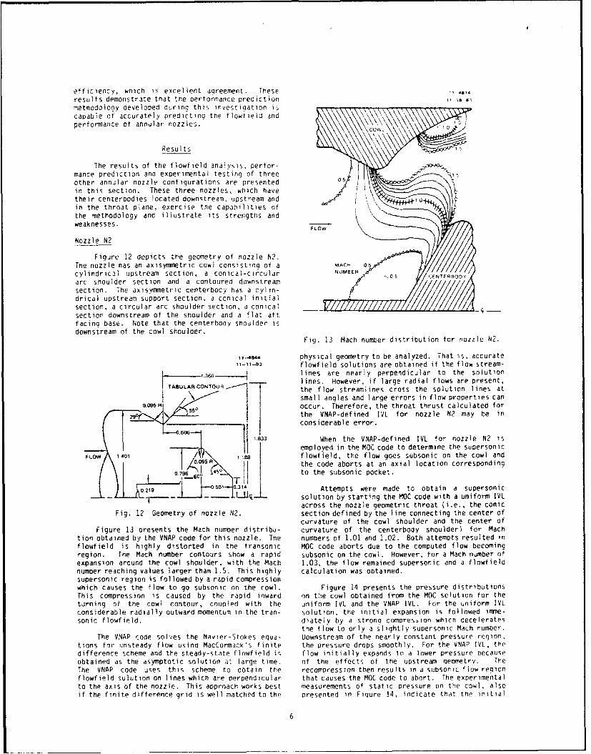
Figure 12 depicts the geometry of nozzle N2.The nozzle has an axisyrmetric cowl consisting of a MAC- ox
cylindrical upstream section, a conical-circular NUMBER 0CENTERSOO
arc shoulder section and a contoured downstream
section, The axisymietric centerbocy has a cylin-drical upstream support section, a conical initialsection, a circular arc shoulder section, a conical
section downstream of the shoulder and a flat aftfacing base. Note that the centerbody shoulder isdownstream of the cowl shoulder.
Fig. 13 Mach number distribution for nozzle N2.
1 -4844 physical geometry to be analyzed. That is. accurate11-11-83 flowfield solutions are obtained if the flow stream-
3t60 lines are nearly perpendicular to the solutionTABULAR lines. However, if large radial flows are present,TABULARCONTOUR/ the flow streamlines cross the solution lines at
small angles and large errors in flow properties can0.09, R occur. Therefore, the throat thrust calculated for
W9 the VNAP-defined IVL for nozzle N2 may be in
considerable error.0.06 1.833 When the VNAP-defined IVL for nozzle N2 is
employed in the MOC code to determine the supersonic
FLOW 1401 /188 I flowfield, the flow goes subsonic on the cowl and9 Rthe code aborts at an axial location corresponding
0. 45 to the subsonic pocket.
0 219 01-0.501 0 i•o 34 Attempts were made to obtain a supersonic-_L _ - -•_ ! l...L solution by starting the MOC code with a uniform IVL
across the nozzle geometric throat (i.e., the conicFig. 12 Geometry of nozzle N2. section defined by the line connecting the center of
curvature of the cowl shoulder and the center ofFigure 13 oresents the Mach number distribu- curvature of the centerbody shoulder) for Mach
tion obtained by the VNAP code for this nozzle. The numbers of 1.01 and 1.02. Both attempts resulted inflowfield is highly distorted in the transonic MOC code aborts due to the computed flow becomingregion. The Mach number contours show a rapid subsonic on the cowl. However, for a Mach number of
expansion around the cowl shoulder, with the Mach 1.03, the flow remained supersonic and a flowfieldnumber reaching values larger than 1.5. This highly calculation was obtained.supersonic region is followed by a rapid compressionwhich causes the flow to go subsonic on the cowl. Figure 14 presents the pressure distributionsThis compression is caused by the rapid inward on the cowl obtained from the MOC solution for the
turning of the cowl contour, coupled with the uniform IVL and the VNAP IVL. For the uniform IVL
considerable radially outward momentum in the tran- solution, the initial expansion is followed imme-sonic flowfieid. diately by a strong compression which decelerates
the flow to only a slightly supersonic Mach number.
The VNAP code solves the Navier-Stokes equa- Downstream of the nearly constant pressure region,tions for unsteady flow using MacCormack's finite the pressure drops smoothly. For the VNAP IVL, thedifference scheme and the steady-state flnwfield is flow initially expands to a lower pressure because
obtained as the asymptotic solution at large time. of the effects of the upstream geometry. TheThe VNAP code uses this scheme to obtain the recompression then results in a subsonic flow regionflowfield solution on lines which are perpendicular that causes the MOC code to abort, The experimentalto the axis of the nozzle. This approach works best measurements of static pressure on the cowl, alsoif the finite difference grid is well matched to the presented in Fiqure 14, indicate that the initial
6

1 1 .445 va Iltes of Measured eff Ic Ien leS, at r:r~~12.-16 83 rCat 05S are due to centeroody wake CTjCT..n rJh~k'i
o5 4oh~ich were determined by eA It Plane Citnt ,ýrv~sir-
UNIFORM fVL Isurveys not discussed lil this parer. *"t nePressure ratios. the O)redicted etticinr.e,approximately 2 percent hiaher than tre measureo
0 values. Tshis difference could be ant ic1iaTpd Sjrine
I ~erally higher than the measured pressures. C
inabilIty01 to More accurately a nalyZe thel ili~wir I pIID. 0 0is disappointing, especially since thfC predicted0 prsenc ofthe ighpresureregion Suggests teiat
0 this type of nozzle could be modif ied to a hictrer
VNAP performing design. This inadecluacy in oredictivE,0 vL capability is identified as a majo c cec iW .0 f0~6~~ the state-of-the-art of nozzle tlowtield anaiysls.
C I Nozzle N3
II Figure 16 depicts the geonietr,/ ri nozzle N3.ii ~The nozzle has an axisyimuietric cowl consisting 0? a~
0,0 ] cylindrical upstream section. a- cenical-cir~ularU arc shoulder section and a conical downstream sec-
tion. The axisymmetric centerbodv hs acy inorircaýupstream support section. .a conical lplt'.a1 etion, a circular arc snoulder section, a contoured
OF ~ section downstream of the shoulde-r and, a Tlat altCOWL COWL facing base. Like nozzle N1. the snoulders it the
VSH4OULDER \centerbody and cowl are at the same axial station.
0'J) 0.5 1.0 1.5 *4
AXIAL STA-ION - INCHES - S8
Fig. 14 Cowl pressures for nozzle N2.
expansion is more rapid than the uniform 1VI solu-tion predicts, but not as rapid as the VNAP IVLsolution indicates. The recompression is clearlyindicated, but the flow apparently remains super-sonic. Note that the computed and Measured pres-!8.3sures agree wellI at more downstream cowl locations. -1IL40
The predicted and measured nozzle efficiencies35 SRCNOR -
for nozzle N2 are compared in Figure 15. The dual L.. _ -)
'1 -A-83
98 Fig. 16 Geometry of nozzle N3
95 - The Mach number contours and Mach l Ines oo-tained by the VNAP and MOC codes are not presented
- since they are very similar to those p-eviouslvz
94 -shown in Figures 8 and 9 for nozzle NI. ýiq,,rvt 117/ compares experimental and predicted pressure dis-
tributions on the cowl for both the uniform IVL and> 92 7 the VNAP IVL solutions with the MOC code. The
Z Predicted pressure distributions are almost iden-90 I:tical and compare very well with the Measured
V ~pressures for higher Pressure ratios. However. as5N 88 - rHEORYshown in Figure 17. the measured pressures at lower
~pressure ratios are higher than the predicted vai-TEST ties. This difference is, attribiuted to tL-w seoara-
tion from the Cowl. This inabillity to) [oredict tlliW86 -separation and compute the resultinfo I lowfield ip
I another major doficiency in state-of-the-irt nozzig
0 lii 20 3 41i 50 ~fiowfieid analysis.NOZZE PESSUE RTIOF igure 18 compares the Measured arld orvo icted
Noz~susNnOnozzle efficiencies for nozzle N.J. 2,rnris inoIyv.the predicted values are less than thie measured
Fig. 15 Efficiency comparison for nozzle N2. efficiencies, out the aqIreement Iexcell1ent at

* -. A~Figure 1. The resulting geometry for nozzle N4 is
*I •4-83 illustrated in Figure 19.0 -ME A.SUREO
O-81
0D u,241 A
UNIFORM o -
S1VL 0 42Z 010 MEASURED 3 I
FDA ALL NP coToULr
NPR I> 15 F - OT
' N : SEPARATED
IVL 0 20 FLOW AT
20 25Fig.
19 Geometry of nozzle N4.O sThe transoni 'c Mach number aistribution ob-
• iEN D tained from the VNAP codei is presented in Figure 20COWL COWL and depicts a highly distorted flowfield. A reqionSHOULDER /of locally supersonic flow occurs at the centernody
I/ I , / shoulder. The flow downstream of this reciono0 0o 1.0 recompresses and remains Suosonic all the way to the
AXIAL, STATION - INCHES nozzle axis.
Fig. 17 Cowl pressures for nozzle N3. -46",-43
10-2-8-398
NOZZLE N3 0'
S• 2094~ MACH
S92 - ___NOZZLE NN
S90 E
8THEORY ASSUM•O--- TESr CENTEROODY
GEOCIMETRY
0 10 20 30 o0 50 60 Fig. 20 Mach number distribution for
NOZZLE PRESSURE RATIo nozzle N4.
Based on simple one-dimensional isentropicFig. 18 Efficiency comparison for nozzles N3 flow theory 7 , it was assumed that the flow would
and N4. choke at the minimum qeometric flow area. This areais a conic surface defined by a line connecting the
higher nozzle pressure ratios. The increased dif- center of curvature of the cowl shoulder with theference between the measured and predicted effi- edge of the base. Snh(e iL was necessary to assumeciencies at lower nozzle pressure ratios merely an extension to the centerbody for the VNAP codereflects the previously mentioned flow separation analysis, it was hypothesized that the assumedphenomena. extension geomet-v influenced the results. Several
different centetoody extension contours were eval-Nozzle N4 uated in an attempt to obtain supersonic flow on the
centerbody or its extension. However, witi theNozzle N4 is a rearrangement of nozzle N3model exception of the previously mentioned supersonic
components which locates the centerbody shoulder pocket at the shoulder, the flow remained subsonicupstream of the cowl shoulder. -his confiquration all the way to the nozzle fi •or rpasonahiiicompletes the annular nozzle design options noted in extension qeometries,
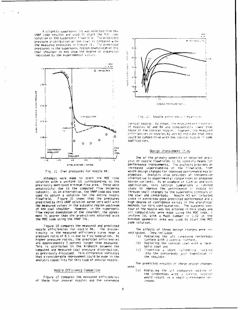
A slight ly Supersonic 1,L was5 Selected !r-lin theVNAP code results ando ujScj tc) Start the 50C
solution or the SuproniSilc iw CCd ti pritr'.pressure distribution oi n t.?Cý i coinOMDre o tn j'iithe measured pressures in Fi' Prod ht, tWedlcpressures lin the supersonic re~gionl downstream 0T the
cowl shoulder do not show the degree 01 ex~DaiSlionindicated bay the e~cerimental i<.5
"0s
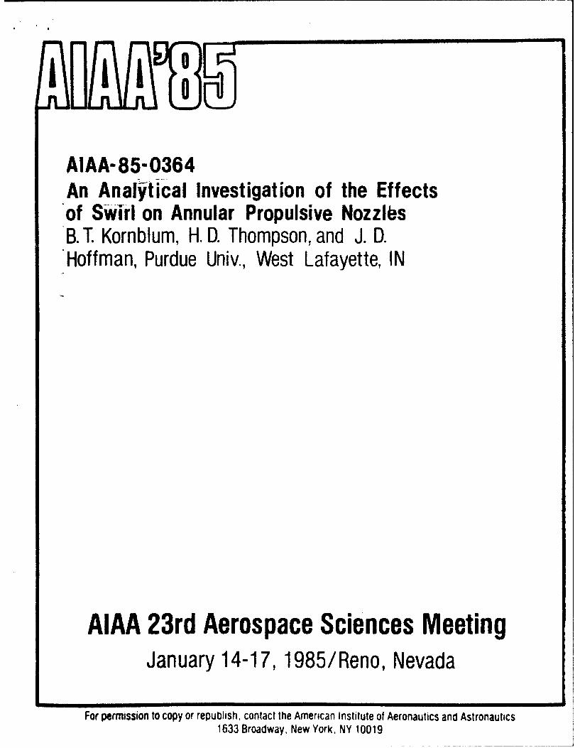
conical nozzle. As shown, 'h e I" ".' ýSO. o1 f nozzles IN? 2ad N4 ire ccnsidr v" owpr than
those otr toe conical Iiozzie O4,wCe*,' rneasutfO
0 ofl10 WOO ies 01 nozzles N! ano N, iri4
-ate that th,(v
003 .0 could be competitive with the conica .2P I ZZ& S sore0 0 aoplications.
0 0:ENO
CENTERROOV sOsg mpoeetYOS*COWLE ico~k
C'00 L S-t0ULOER IOne of the primary Denet its oý detailed anai--10 _QS 0 0 'S ysis of nozzle flowfields is to identify means t-IAXIAL STATION -cs 11CISPerformance improvements. The analysis provides an
increased understanding o ? the f 1 rwf ie Id. Ir Omrig. 21 Cnwl pressures for nozzle N4. which design changes for Improved performance may 0".
proposed. Analysis also provides an inexpensiveAttempts were made to start the MOC code alternative to experimental rconrarisons o-, proposed
solution with a uniform 1VL corresponding to the deSion variants. As an exampie of Sucn an analysispreviously mentioned minimum flow area. These were application, this section summuarizes a ltimitedunsuccessful due to the computed flow becomina Study to improve the performance _* nozzle N3subsonic. As an alternative, the VNAP code was then thrOuqh small Chanties to the supiersonic c-,ntours oTused to obtain a solution for the entire nozzle the cowl and centerbody. Nozzle N3 we- selecteaflowfield. Figure 21 shows that the pressures since it exhibited good predicted performance and apredicted by this VNAP solution agree very wellI with high degree of conifidence exists in the analyticalthe measured values in the subsonic region upstream methods for this configuration. The sixsonic zon-of the Cowl shoulder. However, in the supersonic tour of the nozzle was not al tered in this study andflow region downstream of the shoulder, the agree- all computations were made uiSing the MOC code.-*ment is poorer than the predictions obtained with iniform lVL with a Mach numoer rif 1.012 at thethe MOC code using the VNAP 1VL. minimum geometric area was used to Start the moc
code solution.Figure 18 compares the measured and predicted
nozzle efficiencies for nozzle N4. The discon- The effects of three design changes were rin-
tinuity in the measured efficiency curve near a vestigated. They included:pressure ratio of 8:1 is due to flow separation. At (a) ReplacZing the aft contouret; renterbodyihigher pressure ratios, the predictee efficiencies surface with a conical surfa-e.are approximately 3 percent larger than measured. (b) Replacing the conical iowi with a ',ara-This is attributed to the mismatch between the bolic cowl andcomputed and measured cowl Pressure distribution, 1c) Tnsertirio d short ,Ylindr'ioai %or t !onas previously discussed. This difference indicates into the centerbudv i6,,t crrwnstrcamthat a considerable improvement could be made in the the Shoulder.analysis capability for this type of annular nozzle.
The predicted result, of these opsion chanoeswere:
Nozzle Efficiency Comparison (a) Relplacing the ttit contoured .ect,,orthe centerbody with a m.
1 cvi~ ,',ct,,0OFigure 22 compares the measured efficiencies would result in a Small z.'-tormance
of these four annular nozzles and the reference crease.
9

(b) Contouring the cowl boundary would result pattern, aiso illustrated in Figure i3. rne pres-in a sliqht performance increase (abouz sure distribution on the cowl is primarily deter-0.2 percent). mined by expans)on waves emanating from tne center-
(c) Adding a short cylindrical section to the body surracp just downstream of Characteristic Cl.centerbody would result in a modest per- which originates at the intersection of tie center-formance increase (about 0.8 percent). body and the 'l. These strong expansion waves.
represented by Characteristic C2 in Figure 23, areThe latter approach was selected for testing generated by the rapid turning of the flow around
since it offered the greater potential for pertor- the centerbody shoulder and cause a rapid decreasemance improvement. This nozzle is denoted as N5 and in tne pressure on the cowl. Adding a shortis depicted in Figure 23. The measured thrust cylindrical section to che shoulder of the center-efficiencies for nozzle N5 and those for the refer- body delays the turning of the fiow and thusence nozzle N3 are compared in Figure 24. This translates the attendant pressure decrease on thecomparison verifies the predicted performance in- cowl further downstream. Further study of thecrease and confirms that analytical prediction characteristic pattern in Figure 23 also reveals thetechniques can be used to assess design changes for limiting length of the cylindrical section toperformance improvements, achieve performance benefits. Characteristic C3,
which intersects the end of the cowl, emanates from11-41W the centerbody at a flow angle of approximately 15"-"MI degrees. Thus, changes to the centerbody downstream
OWL -SAME FOR 2ZESiw of this point have no effect on the cowl pressure.Any other features of the flow, specifically thesubsonic-transonic flowfield and the pressure dis-tribution on the centerbody, should not be sicnifi-cantly altered by this modification.
F CL/c •J C"ARACTER"ST'C Summary and Conclusion,
The analytical methods described in this paper"" NOZZE', CENTERBODY are very accurate for conventional converging-
S FOR NOZZL.EHS diverging noLzles and are reasonably accurate forannular nozzles if the radial velocity components inthe transonic region are small. The analytical
INCHES methods provide valuable quantitative informationthat can be effectively used to understand the
--..- flowfield and generate ideas for design improve-CYLINDRICALSECTION ment. Furthermore, the methods are sufficientlyADOEDATSHOULDER accurate that the effects of small differences inFORNOZZLEN5 designs can be accurately evaluated, thus reducing
the amount of experimental work required to optimizeFig. 23 Geometry of nozzle N5. a given design concept.
Hc-tever, there are some deficiencies in the1 ,,851 analytical capability for some annular nozzle flow-
9- fields. These include inadequate transonic flow- -. analysis capability for flows with large radial
velocity components, inability to treat strong9 8shock waves (particularly when the shock waves
- OS0PERCxN3 produce subsonic pockets in the supersonic flow-N IMPROVEMENT field), very poor base pressure prediction methods
and inability to predict and calculate separatedflows. Future improvements in these areas wouldenhance the analytical capability for annular noz-
go /--'-•NOZZLEN5 zles.
Appendix88 - Nozzle Efficiency Definitions
Due to the importance of nozzle thrust onpropulsion system performance, a consistent nozzleefficiency definition must be employed when compar-
* MEASUREOEFPICIENCIES ing the performance cf different nozzle designs.. I I Since definitions of nozzle efficiency in the lit-
C 'C 20 30 40 50 6o erature differ, the objective of this appendix is to
NOZZLE PRESSURE RATIO present a clear exposition of the various efficiencydefinitions, to carefully define the various param-eters that enter into these definitions and to
Fig. 24 Efficiency improvement with recommend a consistent procedure fcr the propulsivecenterbody modification, nozzle efficiency definitions so that meaningful
comparisons can be made between various nozzles.The payoff in adding the cylindrical section to
the centerbody can be explained in terms of cowl Three different nozzle efficiencies can bcpressures by observing the characteristic wave defined. They are:
.0

I. n i--the internal efficiency, which compares For DeLaval nozzles. tie geometri- Trnroa! ae.ethe actual internal performance of the nozzle (i.e., •s defined as tne planar dred adt tht rozzie iMinvacuum performance) to the ideal internal pertor- -cross section and vdiues 95i dcnaroQs Cfttlmance of the nozzle. are ouite close to unitv. Kr ,o riv enri di
nozzles, the choice on Qeometric t oroal aere is !ess2. oAR--the area ratio efficiency, which compares obvious and values ot dýsctiirofe c(e>riir(ent rrjithe actual performance of the nozzle operating in an differ conswderatly irom unity. r, tfict. :neatmospheric pressure environment to the ideal per- determination of the geometric minimum area forformance of the nozzle operating in the same envi- annular nozzles Such as discussed in tnis flaper Yriiyronment. be quite difficult.
3. npR--the pressure ratio efficiency, which com- The actual mass flow rate may ue determinedpares the actual performance of the nozzle operating experimentally, predicted analyticaily or deter.in an atmospheric pressure environment to the ideal mined from empirical discharge coefficient correia-performance of an adapted nozzle with optimum ex- tions. In this study, reference mass flow rate waspansion operating in the same environment, determined using conventional steaoX one-dimen-
sional Isentropic nozzle flow theory' ana actualThe effect of the atmospheric pressure envi- mass flow rate was predicted using the Viscousronment on performance is determined by the nozzle Nozzle Analysis Program (VNAPI code4.pressure ratio (NPR), which is defined as:
Figure A-i also illustrates Tne relerenceNPR = Po/Pa (A-i) ideal exit area of the nozzle, it can be defined inseveral ways, for example:
where P0 is the nozzle stagnation pressure and Pa is (1) the nozzle maximum intern1i area Apl, orthe ambient pressure. (2) the nozzle maximum internal area pls thecowl base area 9?.Each of the three nozzle efficiency defini- Since the flow always separates trom the centervodytions has some merit. The internal efficiency aft face and forms a free-pressure boundary, themeasures the thermodynamic efficiency of the inter- reference ideal area could be defined as either ofnal expansion process and is independent of the the preceding areas minus the area occupied by thenozzle pressure ratio. The area ratio efficiency separation region, for example A. in Figure A-i.includes the thrust loss due to the ambient pressure This choice has some merit from a fluid dynamicacting on the backside of the nozzle. The pressure point of view for annular nozzles, but it isratio efficiency includes the loss in performance impractical since the size of the separation regionwhen the nozzle is not adapted for operation at a is difficult to determine. In the present study,particular nozzle pressure ratio. the reference ideal exit area of the nozzle isdefined as Ael in Figure A-i.
The reference ideal thrusts required in theseefficiency definitions also require careful speci- Once the reference ideal choking area and thefication of the reference ideal choking area and the reference ideal exit area have been specified, thereference ideal exit area of the nozzle. reference ideal thrust for internal efficiency and
area ratio efficiency can be computed using conven-Figure A-I illustrates the reference ideal tional steady one-dimensional isentropic nozzlechoking area A*. It is the area required to pass the flow theory, The reference ideal thrust for pres-actual mass flow rate and is smaller than the sure ratio efficiency can be computed for a speci-geometric minimum (throat) area At. Those two areas fied value of nozzle pressure ratio by the sameare related by the nozzle discharge coefficient C[, techniques.which is defined as:
Figure A-2 presents the three nozzle effi-CD = A*/At = iact/mref (A-2) ciencies as a function of nozzle pressure ratio fora nozzle having a reference ideal area ratio of 3:1.where &act is the actual mass flow rate and iiref (This corresponds to an adapted pressure ratio ofis the mass flow rate corresponding to steady approximately 20:1 for a gas with a specific heat
one-dimensional isentropic choked flow at the geo- ratio of 1.30.) The assumed internal efficiency ismetric throat area. 0.97 and the assumed disctarge coefficient is 0.94.The area ratio efficiency and the pressure ratioII-A838 efficiency have been computed from conventional
W-28-83 steady one-dimensional nozzle flow theory and the______________________________assumed values of internal efficiency and dischargecoefficient. The area ratio efficiency shows the
loss in performance of the particular nozzle due toFLOW A' the atmospheric pressure, while the pressure ratio
efficiency shows the loss in performance due toimproper matching of the design area ratio with theoperating Pressure ratio. The two efficiencies are--- /_ equal only at the design area ratio.
FREE PRESSuRE The pressure ratio efficiency is the mostBOUNDARY meaningful for comparing different nozzle desiqns
operating Over a range of nozzle performance -atios.Consequently, that efficiency was employed in theFio. A-i Reference areas for an annular nozzle, present investigation.
11

_A9-836
98
11 - 97 PERCENT
/
96 I i
91
N; I •AGATEO0Z j PRESSURE
RATIO
97 -
I o1 30
a 10 20 30 40 so 60
NOZZLE PRESSURE RATIO
Fig. A-2 Comparison of nozzle efficiencydefinitions.
References
1. Rao, G.V.R ., "Exhaust Nozzle Contour for Opti-mum Thrust," Jet Propulsion, Volume 28, No. 6,pp. 377-382, June 1958.
2. Schorr, C.J. and McKenna, R.F., "ConstantChamber Pressure Throttling of an Expansion-Deflection Nozzle," AIAA Paper 69-435, June1969,
3. Zucrow, M.J. and Hoffman, J.D., Gas Dynamics,Vol. 1, Chapter 10, John Wiley and Sons, ewYork, 1975.
4. Cline, M.C., "VNAP: A Computer Program forComputation of Two-Dimensional, Time DependentCompressible, Viscous, Internal Flow," ReportLA-7326, Los Alamos Scientific Laboratory. LosAlamos, NM, November 1978.
5. Thompson, H.D., "A Method of CharacteristicsProgram for Computing Annular Nozzle Flow-fields," Report ME-TSPC-83-05, Thermal Sci-ences and Propulsion Center, Purdue Univer-sity, West Lafayette, IN, June 1983.
6. MacCormack, R.W., "The Effect of Viscosity inHypervelocity Impact Cratering," AIAA Paper69-354, April 1969.
7. Zucrow, M.J. and Hoffman, J.D., Gas Dynamics,Vol. I, Chapter 4, John Wiley and Sons. NewYork, 1975.
12
AIAA-85-0364An Analytical Investigation of the Effectsof Swirl on Annular Propulsive NozzlesB. T. Kornblum, H. D. Thompson, and J. D.Hoffman, Purdue Univ., West Lafayette, IN
AIAA 23rd Aerospace Sciences MeetingJanuary 14-17, 1985/Reno, Nevada
For permission to copy or republish, contact the American Institute of Aeronautics and Astronautics1633 Broadway, New York, NY 10019

AN ANALYTICAL INVESTIGATION OF THE
EFFECTS OF SWIRL ON ANNULAR PROPULSIVE NOZZLES
Barbara T. KornblumLawrence Livermore National Laboratory
Livermore, California 94550
and
H. Doyle Thompson and Joe D. HoffmanPurdue University
West Lafayette, Indiana 47907
Abstract Subscripts
An analytical perfomance prediction A to F denotes geometric stationsmethodology for annular propulsive nozzles B,CP,IVL denote bass, cowl, plug,with swirl introduced in the combustor and initial-value lineupstream of the nozzle is presented. The tx,y denotes partial differentiationapplication of that methodology to aspecific nozzle design for a free vortexswirl distribution is discussed. IntroductionDischarge coefficients, specific impulses,and wall pressure distributions are Recent studies indicate that thepresented. These numerical studies show introduction of swirl ahead of the combus-that the discharge coefficient and the tor in axisymmetric dump combustors canthrust decrease as the amount of swirl have very beneficial effects on theincreases, but that the specific impulse combustion proces¶. Buckley, Craig, Davisis essentially uninfluenced by the swirl. and Schwartzkopf found that swirl bothThis methodology will enable nozzle reduced the reattachment length of thedesigners to account for the effects of combustor flowfield (thereby reducing theswirl in nozzle design- overall combustor length needed for good
performance), and helped eliminate des-tructive very low frequency instabilities.
Nomenclature They further concluded that (in the rangeof swirl intensities of their study)
a speed of sound "losses in thrust due to residual swirl,
CI-C constants specifying tangential at least to the sonic point of the nozzle,velocity distributions are negligible.*
Sthrust Scharrer and Lilley2 made five-holeM mass flow rate pitot probe measurements of the effects ofN Mach number swirl in simulated dump combustors fol-P static pressure lowed by a nozzle. They observed a signi-P stagnation pressure ficant interaction between the swirlingR gas constant flowfield in the simulated combustor andS swirl number the nozzle flowfield. Their major objec-T stati temperatture tive, however, was the measurement of theT stagnation temperature confined turbulent flow in the simulatedu axial velocity component combustor, not the nozzle flowfield. Con-
v radial velocity component sequently, their nozzles were simply used
w tangential velocity component as downstream blockage components. Both
x,y axial and radial coordinate, nozzles used in their studies were conven-respectively tional converging nozzles without center-
Y inner radius of the annular flow bodies.geometry 3
Y outer radius of the annular flow Conley, Hoffman and Thompsongeometry presented an analytical and experimental
7 specific heat ratio investigation of the performance of annu-p density lar propulsive nozzles without swirl. The* tangential coordinate present work is an extension of the per-
formance prediction methodology developedby Conley, Hoffman, and Thompson to
1-iiruate Student in Mechanical include the effects of swirl introduced inEngineering. Presently with Lawrence the combustor on the performance of artnu-Livermore Laboratory. lar propulsive nozzles.
+ Professor of Mechanical Engineering. A similar study performed by Dutton4
Associate Fellow AIAA. shows trends similar to the resultsobtained in the present investigation for
++ Professor of Mechanical Engineering. conventional convergent-divergent nozzlesMember AIAA.
CogM V AmutamE l.omsie of Ae'souutm madA.•Smevea Inc.. IMU. All vgbb •ewe. 1
without centerbodies. The present inves- air as it passes through the swirler. Thetigation is concerned with convergent- design of the swirier and the interactiondivergent nozzles with centerbodies. of the swirl witn the combustion process
are of paramount importance in an actual
The objective of the present work was system design. In the present study ofto analytically investigate the effect of the effects of swirl on nozzle perfor-swirl on the transonic and supersonic Mance, a tangential velocity distributionflowfields in annular propulsive nozzles, representative of what might be producedand to determine the effects of swirl on by a swirler and a combustor is simplymass flow rate, thrust, and specific assumed to exist at the nozzle inlet.impulse.
Buckely, Craig, Davis, andPerformance Prediction Methodology Schwartzkopf experimentally investigated
four types of tangential velocity distri-Geometric Model butions at the swirler exit. They are:
The geometric model considered inthis investigation is illustrated in Fig. Constant angle: w-C1. Air enters at Station A and flows (I)through a swirler where tangential momen- Forced vortex: w-ctum is transferred to the air to give the 2Y (2)desired tangential velocity distribution Free vortex: w-C 3 /Y (3)at Station B. Station 8 is followed by asudden expansion dump into the combustor Rankine vortex: w'(C 4 /y)fl-exp(-y /y 2 )](4)2inlet at Station C. Combustion takes 4/ 14place between Stations C and D, where thestagnation temperature T risescorresponding to the amount of 0 fuel added where w is the tangentl velocity, y isand the stagnation pressure P descreases the radial location, Y is the outeran et radius of the swirleadC oC rslightly due to friction, mixing, and heat radi s o te sirler, and C to d areaddition. The combustion products constants specified to achieve ihe delxredaccelerate in the nozzle to the choked tangential velocity distribution. Incondition at the nozzle throat, Station E, order to provide a basis for comparison ofafter which the flow continues to different swirlers, a swirl number S isaccelerate supersonically from Station E employed, which is defined asto Station F.
Y uwy dyA 9 C 0 E F 1 (5)
Y u 2uydy
Y2 Y'
cCOMBUSTOR NOZZLEThe only tangential velocity distri-
SWIRLER bution considered in the present study wasMthe free vortex distribution given by Eq.(3). A centerbody exists throughout the
---------------- tflowfield, so the singularity associated
with the core of a free vortex does notoccur in this flowfield. For a free vor-
Fig. 1. Geometric model. tex, yw - C so that at a uniform flowsection where •he radial velocity v - 0and the axial velocity u is uniform, Eq.(5) simplifies to
The concern in the present study was
the effect of swirl introduced in theswirler on the performance of the nozzle C3(i.e., mass flow rate, thrust, and S- u-- (6)specific impulse). Consequently, the 2swirler, the sudden expansion dump, andthe combustor are not modeled in detail in Consequently, the swirl number S is a sim-the present analysis. Emphasis is placed ple function of the geometry (i.e., Y)on the nozzle flowfield. Even so, some and the axial velocity u. For a givenattention must be given to the swirler, value of C3 at the nozzle inlet, Stationsince it Is the source of the swirl in the D, the swirl number SD can be calculated.nozzle flowfield. Thus,
Swirler C
The ewirler is a set of axial flow D "uT (7)guide vanes that imparts the desired D 21
tangential velocity distribution to the
2

The corresponding values of swirl by the nozzle Is directly related to thenumber at the combustor inlet SC, swirler nozzle exhaust velocity. For rocketexit S_0 and nozzle throat S_, can be enqines, the cross thrust produced by theestxma ed from the known valuE of S and nozzle is also the net thrust. However,Eq. (6). The major process occRring for airtireathing engines (turbines andbetween Stations C and D is the increase ramrets), the net thrust is the differencein stagnation temperature T due to between the nozzle gross thrust and thecombustion. For a Rayleigh0
line flow inlet ram drag. Consequently, all losses(i.e., heat addition at constant area) in in nozzle qross thrust for airbreathers
the absence of swirl, it can be shown that are magnified several times in net thrust,and it is imperative that the nozzle effi-ciency be as large as possible.
UDD . RTo ÷ +lUDu oD + Ty- 'D Fiure 2 illustrates the thrust pro-
i RT(+8)' ducing components of a generic annularoc +7 c nozzle. The nozzle thrust is composed of
Thus, for known values of UDh TD' and the thrust developed across the supersonicToc, uc can be calculated, so that initial-value line F I the thrustdevelopd by the presiuV~e acting on the
cowl F the thrust developed by the pres-
SD C 3 iUDY2 D Uc sure asting on the plug FP, and the thrustC C3 /UCY 2 D -U (9) acting on the plug base F8.
At the sudden expansion dump loca-tion, Y2 changes from. Y 2 to Y " For Cowl Fconstant mass flow rate m, and neg ectingcompressibility effects, which are small,Fu is inversely proportional to the flow FWIVLa~ea, which is directly proportional to F FY2 " Thus, Plug-
UB . uc (Y2c /Y 2 ) 2 (10)
Fig. 2. Thrust producing components ofSubstituting this result into Eq. (6) an annular nozzle.yields
-C C 3/UC Y2C Y2C (11) The relative magnitudes of these
3 /UBY B Y2B thrust components depend on the nozzledesign. For nozzle geometric area ratiosbetween 3 and 5, as considered in thisAt the nozzle throat, Station E, u. study, the magnitude of the supersonic
is three to five times as large as uD, an initial-value line thrust is approximatelyY,, may be anywhere from 50 to 90 percent 80 to 85 percent of the total thrust, the0 YAD When specific values are given, cowl thrust is from 10 to 15 percent ofSE caA be calculated from SD' the total thrust, and the plug and basethrusts comprise the remainder.
Consequently, for a specified valueof the swirl yw at the nozzle inlet, the The supersonic initial-value lineswirl number SD at the nozzle inlet can be thrust Fi is given bycalculated. Knowing the other motoroperating parameters, the values of theswirl number S can be estimated at other u dm' P(locations in the motor. ILVL L V 2ry dy (12)
Performance Model The cowl thrust FC is given by
The propulsive nozzle is the thrust F,1producing component of jet propulsion Cowl P 2ry dy (13)engines such as rockets, turbojets andramrets. The function of the propulsivenozzle is to convert the random thermal The plug thrust Fp is given byenergy of the gases entering the nozzleinto directed kinetic energy at the nozzle Fexit, thus creating a thrust on the pro- P Plug P 2ry dy (14)pulsive system. The expansion processmust be accomplished as efficiently aspossible, since the gross thrust developed
3

The plug base thrust F is given by The VNAP code was used as the
B sudsonic!transonic flowfield predictioncode tor tne annular nozzle performance
F -PA (15) prediction methodology developed by Con-5 B ley, Hoffman, and Thompson. The VNAP
code solves the Navier-Stokes equations
where P is the average base pressure act- for two-dimensional tplanar or axisym-
ing on Phe truncated plug base area A metric), Lime dependent, compressible flowusing the second-order accurate, MacCor-
From Egs. (12) to (15), it is seen mack flinite diff-rence scheme. Inviscid
that the flow properties across the super- flowfields can be yived by setting all of
sonic initial-value line, the pressure the viscous teri' to zero, which yields
distributions along the cowl and the plug, The Euler equations. An explicit artifi-
and the base pressure must be calculated cial viscosity is included for shock wave
to enable the -alculation of the nozzle calculations. The fluid is assumed to be
performance. a perfect gas. The steady state solutionis obtained as the asymptotic solution for
Flowfield Model larae time.
The computational grid employed byThe accuracy and efficiency of nozzle the VNAP code is a transformed equally
performance prediction techniques are spaced grid. Equally spaced lines of con-highly dependent on the fiowfield model otant 1 normal to the x-axis comprise onechosen to represent the actual flowfield. of the transformed coordinates. EachIn the present study, the flowfield model vertical line segment between the plug andis based on the following assumptions: the cowi is divided into a number of
equally spaced increments. Lines of con-
I. steady axisymmetric flow, stant 77 join these points. The physical2. inviscid nonconducting flQid, grid is illustrated in Fig. 3. The3. no body forces, transtormation equations are4. thermally and caloricaiiy perfect gas.
and5. separation and base pressures pre- Y - YC(X)
dicted from empirical correlations. = x and -c (16)
The governing equations consist of thecontinuity equation, the component momen- where yj(x) is the :owl contour and yp(x)tum equations, the energy equation and the is the ýlug contour.thermal and caloric equations of state. Adetailed discussion of these equations ispresented in Ref. (5).
The choice of a numerical method, or Y
methods, to solve these governing equa-tions is also crucial to the success ofthe performance prediction procedure. Asubsonic/transonic solution is required todefine the supersonic initial-value linethrust, while a supersonic solution isrequired to define the. cowl, plug, andbase thrusts. Experience has shown thatsubsonic/transonic flowfields can be ade-quately determined from the steady statesolution to finite difference time march-ing solutions, whereas the method ofcharacteristics is the most accurate meansfor determining supersonic flowfields in Xnozzles. Therefore, the numerical methodsselected for the performance predictionprocedure in the present study are a fin- Fig. 3- Typical SNAP grid.
ite difference time marching approach todefine the subsonic/transonic flowfield,and a method of characteristics approachto define the supersonic flowtield. In the present investioation, the
Subsonic/Transonic Flowfield VNAP code was modified to account for the
presence of swirl in the flowfield by
The finite difference code developed adding the tangential momentum equation to
to solve the suosonic/transonic flowfield the set of governing equations and the
is a modification of the VNAP (Viscous tangential velocity component to all the
Nozzlg Analysis Program) code developed by governing eauations, where appropriate.
Cline to include the effects of swirl. Since tne flowfield is axisymmetric, all
The resulting code is called SNAP 'Swir- derivatives with respect to the tangential
ling Nozzle Analysis Program). direction e are zero, even though the
a

tangential velocity component w ISnonzero. The governing equations for thisflowfield are:
Pt + up +r + vp + Pu + pV pv/y = 0 (17)
Put + OUUx + pvuv. + P = 0 (18)
2P + puvx + pvvy + Py - Pw2/y / 0 (19)
wt + uw + VW + vwiy -0 (20) Fig. 4. Swirl specIfication model.
Pt + uPx +vP - a2 (pt+U x+VP ) - 0 (21)
nozzle in the following manner. Afterwhere u, v, and w are the velocity com- each time step, the mass flow rate isponents in the x, v, and e directions, intearated across the flowfield at eachrespectively, P is the pressure, p is the axial location, from the cecteroodydensity, a is the speed of sound, and sub- iim - 0) to the nozzle wail (i - mtotal;'scripts denote partial differentiation. The fractional mass flow rate a eachFor a perfect gas, radial station is calculated by dividing
the calculated mass flow rate at thatradial station by the total mass flow rate
P - pRT (22) at that axial location. The resultingfractional mass flow rate is then used tointerpolate for the swirl yw at the
2 corresponding computational grid point bya - APC (23) quadratic interpolation of the swirl func-
tion yw(•i) computed at Station B. Theswirl velocity w is then computed by
Equation (20) can be written as dividing the interpolated value of theswirl yw by the value of y at the computa-
D(yw) _ 0 (24) tional grid point.Dt
This procedure is consistent with thegoverning partial differential equations
which is in substantial derivative form. only at the steady flow limit, becauseEquation (24) states that the swirl yw actual unsteady pathlines are not tracked.remains constant on the pathlines of an Essentially, this procedure matches a nor-unsteady flowfield and on the streamlines malized steady mass flow rate at theof a steady flowfield. Consequently, if swirler exit to a normalized mass flowthe distribution of the swirl yw is speci- rate at each point in the nozzle. In anfied at the nozzle inlet, that swirl dis- unsteady flow, these two points would nottribution will be preserved throughout the necessarily lie on the same pathline.flowfield. Thus, two modifications to However, at the steady flow limit, theseVNAP were made to include the effects oI two points do lie on the same streamline.swirl: (1) tracking the streamlines ofthe flowfield so that the values of swirl In a typical run, 800 to 1000 timeyw at the nozzle inlet can be tracked steps are taken by the SNAP code to relaxthrough the flowfield as the streamlines the initially assumed one-dimensionalchange r~dial position, and (2) adding the flowfield to a steady state. An initial-term pw /y to Eq. (19), where w is com- value line along which the prolection ofputed from the known value of swirl yw the Mach number in the xy plane is super-along each streamline, sonic is then specified across the throat
region. Values of the projected MachThe initial tangential velocity dis- number and flow angle along that line are
tribution w(y) is specified at Station B, determined from the SNAP flowfield byillustrated in Fig. 4. Station B is an interpolation. Least squares quadraticupstream station ahead of the nozzle bivariate interpolating polynomials areinlet. Typically, Station B is the exit fit to the nine closest SNAP grid pointsof the swirler. The mass flow distribu- to each initial-value line point. In thistion A(y) is computed across Station B, so manner, a supersonic initial-value line isthat the swirl yw is a known function of determined, which can be used to initiateA•. This function, yw(d), is then used to the solution of the supersonic flowfieldcompute the swirl yw at each point in the by the method of characteristics.
5

Supersonic Flowfield
The supersonic flowfield is calcu-lated by the method of characteristics forsteady two-dimensional flow. For steadyflow, Eqs. (17) to (21) become
upx +vp +PU + + +v/ - 0 (25)Vy ux py
puu x + pvU + -+ J (26)
puvx + pvvy +P - Ow/y - 0 (27)
Fig. 5. Typical left-running Mach linesfor supersonic annular swirling
Uwx + VWy + vw/y- 0 (28) flow.
continued until the nozzle exit lip point,
up 2 point E, is determined. Left-running Mach
x + vP y a2(UPx + vp - 0 (29) lines are then terminated at the lastright-runnina Mach line emanating fromPoint E. This orocedure is continued
Equation (28) can be written as until point F, at the end of the plug isdetermined. The base pressure on the faceof the truncated plug is computed from the
D(yw) 0 (30) following empirical correlation:which-- stte o .4 .(31)•
which states that the swirl yw is constant Pbase 0.846 1.3along streamlines.
The derivation of the characteristic The above procedure determines all ofand compatibility equations corresponding the data required to evaluate the thrustto Eqs. (25) to (29) is a straightforward, components illustrated in Fig. 2.although somewhat lengthy, procedure. Thederivation is presented by Kornblum and ResultsThompson . The results are not presentedhere. In brief, three characteristics are Nozzle flowfields were comouted fordetermined in the xy plane: the stream- 12 cases. Figure 6 defines the flowfieldline and the right- and left-running Mach geometry for all 12 cases. Only free vor-lines. Three compatibility equations are tex swirlers were considered. The swirldetermined along the streamline and one strength was characterized by the yw pro-compatibility equation is determined along duct, where y is the flow radius (ft), andeach Mach line. These five compatibility w is the trangenital velocity componentequations are used to solve for u, v, w, (ft/sec). Values of the swizl yw of 0,P, and p. 50, 100, 150, 200, and 250 ft /sec were
analyzed for stagnation temperatures atA direct marching method of charac- the nozzle inlet of 2500 R and 3500 R.
teristics procedure is employed to solve The stagnation pressure was 35 psia inthe characteristic and compatibilty equa- every case. In all cases, the specifictions. The solution procedure constructs heat ratio 7 - 1.40 and the gas constant Rthe Mach line network illustrated in Fig. - 53.35 (ft-lbf)/(Ibm-R). The scope of5. The characteristic and compatibility the parametric study is defined in Tableequations are integrated numerically by i.the second-order accurate modified-Eulerpredictor-corrector method. The solution A s C D £ Fis initiated from the supersonic initial-value line, line TTI, determined from theSNAP analysis. Left-running Mach linesare emanated from line TT', starting at COMBUSTOR NOZZL
point T, and continued across the flow- SW ,field until they intersect the cowl, con- W itour TE. The last such Mach line from L45 -- i7point T' intersects the cowl at point T".Left-running Mach lines are then ori- r-j-ginated from points on the centerbody andcontinued across the flowfield to inter- Fig. 6. Nozzle geometric specification-sect the nozzle wall. This procedure is
6

Table i. Scope of the parametric stud'.
Swirl yw T "
Run (ft 2/sec) R \
1 0 2500 MACH2 50 2500 NUMBER 5 ' A,3 100 2500 •4 150 2500 PLOW i'.5 200 25006 250 2500 , • ,
7 0 35008 50 35009 100 3500
10 150 350011 200 3500 PUG12 250 3500
The swirl number S defined by Eq. (5)varies with axial location in the flow-field. At the nozzle inlet (x - - 6-0 in. Fig. 7. Transonic Mach number distributionfo5 the SNAP analysis), a swirl vw of 50 for Case 7.ft /sec corresponds approximately to aswirl number S - 0.14 for T - 2500 R, andS - 0.12 for T - 3500 •. The swirl Thus, Fig. 7 is representative of thenumber S varies approximately linearly plots for all 12 cases. There are somewith the swirl yw at that location, so differences, however, which are discerni-that the range of yw values considejed in ble in the integrated mass flow ratethis study (i.e., 0 to 250 ft /sec) values tabulated in Table 2.corresponds to swirl numbers between 0 and0.7 at the nozzle inle' At the nozzle Figures 8 and 9 present the left-throat, the swirl numbers are, of course, running Mach line pattern in the xy-planemuch smaller. For the nozzle geometry for the supersonic flowfields for Cases 1considered here, the swirl numbers at the and 6, respectively. Case 1 is the nothroat are about 30 percent of the values swirl case with T = 2500 R. Case 6, yw -at the nozzle inlet. 250 ft /sec and0 T - 2500 R, represents
the largest swirl cave considered in theThe swirl number upstream of the study. In Figs. 8 and 9, the left-running
combustor depends on the amount of heat Mach lines emanating from the plug surfaceadded in the combustor, as indicated by are terminated at the right-running MachEqs. (8) and (9). For stagnation tempera- line emanating from the end of the cowl.tures of approximately 1000 R en ering the Comparison of Figs. 8 and 9 shows thatcombustor and a swirl yw - 50 ft /sec, S - swirl has the effect of compressing the0.37 for T - 2500 R and S - 0.44 for T - flow on the plug surface, resulting in3500 R. ýh swirl number varies approoi coalescing left-running Mach lines.mately linearly with yw, so the range ofyw values considered in this studycorresponds to swirl numbers between 0 and2.20 at the combustor inlet. MAZ- LIN,
The swirl number at the swirler exit, CWupstream of the sudden expansion dump, '. '
depends on the geometry of the suddenexpansion, 2 as expressed by Eq. (ii). Foryw - 50 ft /sec, S - 6.24 for T - 2500 Rat the nozzle inlet, and S - 0.29 for T =3500 R at the nozzle inlet. The swirlnumber varies approximately linearly withyw, so the range of yw values consideredin this study corresponds to swirl numbersbetween 0 and 1.45 at the swirler exit.
Figure 7 presents constant Mach BASE
number lines in the transonic region forCase 7 (T - 3500 R, yw - 0) as computed "by the BNAP code. Comparisons with theconstant Mach number lines for the other x. iL11 cases show differences in the thirdsignificant figure for most quantities. Fig. 8. Left-running Mach lines for
Case 1.
7

Figure 11 presents the pressure dis-RGHKT-RUNWING tribution on the cowl for Cases I and 6.
,• The pressure distributions on the cowlsurface are almost indistinguishable forall swirl values. There are son'e differ-ences, however, which are discernable in
7 - the integrated thrust values tabulated inTable 2. Because the cowl projected areais much larger than the plug area, a much
•- smaller pressure difference is required toproduce distinguishable differences in theintegrated thrust values on the cowl.
-1 AD
.7
Fig. 9. Left-running Mach lines forCase 6.
Figure 10 is a comparison of thepressure distributions on the plug for
Cases 1 and 6. There is a substantialpressure increase on the plug due to theeffects of swirl. Unfortunately, the area 3over which the pressure increase acts issmall, so the increase in thrust is onlymodest. The pressure distributions forthe intermediate swirl intensities liebetween the results of Cases I and 6 in avery orderly fashion.
0 Z 3 4 5 6 7
Fig. 11. Pressure distributions on thecowl for Cases I and 6.
Table 2 summarizes the mass flowrates, thrusts, and specific impulses forthe 12 cases studied. Cases 1 to 6 arefor T - 2500 R, and Cases 7 to 12 are for
7 T 0 3500 R. The reference (one-dmensional) mass flow rate for Cases I to6 is m - 21.9842 Ibm/sec, and for Cases7 to 1
deifo vu 18.5800 Ibm/sec. MassR ~flow values wir-P determined by integratingZ C.e6 across the initial-value line that is gen-
Serated from the results of the SNAPanalysis. The discharge coefficients areplotted in Fig. 12. The values decrease
N .. with increasing swirl in a smooth, con-/ '-.--.-" sistent manner and indicate consistency inthe initial-value data obtained from the
ywOO SNAP analysis. Thrust value3 were com-puted from the results of the method of
"" -4 5 characteristics fMOC) analysis. The0 I 2 individual thrust contributions from thex, • initial-value line, the cowl, the plug,
and the base (illustrated in Fig. 2) aretabulated separately. All values arereferenced to zero ambient pressure. The
Fig. 10. Pressure distributions on the base pressures were computed from Eq.plug for Cases I and 6. (31).
8

Table 2. Comparison of performance Parameters.
Swirl yw TO Mass Flow CD Isp
Run (ft /sec) R (Ibm/sec) (ibf-sec/lbm)
1 0 2500 21.49.1 0.9776 141.5942 50 250r: 21.456 0.9760 141.625
3 100 2500 21.350 0.9712 141,665
4 150 2500 21.173 0.9631 141.753
5 200 2500 20.929 0.9520 141.894
6 250 2500 20.611 0.9375 142.161
7 0 3500 18.163 0.9776 167.538
8 50 3500 18.142 0.9764 167.5699 100 3500 18.078 0.9730 167.602
10 150 3500 17.971 0.9672 167.67011 200 3500 17.823 0.9593 167.774
12 250 3500 17.633 0.9490 167.952
Thrust (lbf)
Run Ivl Cowl Plug Base Total
1 2582.08 298.26 155.34 7.32 3043.00
2 2577.11 298.06 155.57 7.96 3038.703 2562.23 297.45 156.28 8.59 3024.55
4 2537.58 296.44 157.53 9.79 3001.34
5 2503.38 295.02 159.7i 11.93 2969.706 2459.43 292.67 162.17 15.82 2930.09
7 2582.08 298.26 155.34 7.32 3043.008 2578.53 298.11 155.51 7.90 3040.65
9 2567.89 297.68 156.01 8.34 3029.9210 2550.23 296.96 156.88 9.14 3013.2111 2525.67 295.95 158.17 10.45 2990.24
12 2494.37 294.63 159.87 12.63 2961.50
The following observations can Demade from the results obtained in this
0.98 study.
1. The data are extrtemely consistentgiving a high degree of confidence in thetrends. (We also believe the absolute
0 0.9 3500R values are reliable.) The thrust valuesfor Cases 1 and 7 are essentially identi-cal. This is, of course, what one would
0. hope, since changing the stagnation tem-perature does not affect the absolutethrust values. However, the initial-value
-94 -,2500R line calculated by the rNAP --ode might beexpected to be somewhat different. sincethe flow speeds and permissible time steps
0.9 for those calculations are different.This result gives confidence in the con-
0 100 200 sistency of the results.o 1o 20 300
Y W'Z/1see 2. For those applications for which
vw < 100 ft'/sec, the effect of swirl onthe mass flow rate and thrust values is
Fig. 12. Discharge coefficients, very small and can probably be ignored inpreliminary design and overall performanceconsiderations. It is probable that this

ovserv at iofl is a~5 ;.s, vt O a-' id 'o TIno ýa ýt- .man, loefree vortex swirlers. Jn Thompson D , "An Analyt r-
:a_! •ro •xFerimentaI 'nvestigation of3. Even at nigner rw.L vaiues. 1no AnnuAr: opu sive Nozzies," AIAA
specific impulse of tne no eC z i ea er n4- 28>, JrnuAry 1984.degraded vy swirl The cal:u.at ions Onowsome increase in I wltrý swir2. Tnere- 4. D)utton,... Craig, *Time-Dependentfore, if hgqn swirl itCe usesa. ae caicuiat;ons of Swirling Nozzleeffects f ,iw Ir on nozzle thrust :an L'e Flow," Final Report, 1983 U'SAF-SCEEEzompensatej for in the uesicn Dy Crreas Suwne Faculty Researc n Proaram, Airino the throat area to'÷ 7r.0e!sare Or me ; r i.:e o. Scientif Ic Research,decreased mass flow rate. -nus :ncreaslnq August 8the thr ust o the required vailue witr outany ioss in nozzle elficlen\'. .. Zucrow, M.J. and heofman, J.D. , Gas
Dynamics, Vol. Chapter I0, Jon-4. When the cowl arid plug sur'aces Wiley nan Sons. New Jork. 1975.
are contoured to optimize tne pertormance,tne optimun contour w'i 0rooaoly oe h. C.Ine MC., "VNAP- A Computer Pro-affected by the presence ot swr:ir tre (ram fCr Computation ot Two-flowfield. Dimensioriah , Time-Ziependent, Viscous,
Internal Flow,* Report LA-7326, LosConclusions Alamos Scientific Laboratory. Los
Alanos. NM S7545, INove.rwer 1978.
An analyvtical pertcrmance predictLon
methodology for analyzing the effects .t Mac'crrmacK, F.W. "The Effect of
swirl in annular prcous-Ive ro~zces nag Z escosIty V n Hyperveiocit. impacteern developed. Computed :esu ts tom a 'amer:n. a AAA iaper 69-354, April
series of swirl intensities :or :tee vor- i969.tex swirlers are extreme-y consistent andindicate a nlan re: ar)tv 1-V tine 8. Kornnium, S.T. and Thompson, H.D. Aresults. swlrý decreases :ne discnarae Method or Characteristics Program forCoeffý-.ent of a nozzle out nas very -it- Comput inc Annular Nozzle Flowfieldstie effect on tne vacuum specif:z impulse, with 5wirI Report ME-TSPC-84-O1,
Thermal Sciences and PropulsionFor swirl :ntensities cften encoun- Center. Purdue iniversity, West
tered in ramiet and turbolet applications, Lafavette. :N, July 1984.the effect. cf swirl or. the nozzle perfor-Mace Is small, and can prooabiy Deneglected •n preliminary aesign and per-formance calculations-
Exper:menta' verif .cation ot tleresults :s needed. Applicaticn of tner.ethodology to otne: tnan free vortexswirlers is needed.
Acknowledoements
This work was sponsored by the AeroPropulsion Laboratory, Air Force Wriýnt-Aeronautical Laboratorles, Wright-Patterson Air Force Base, OH 45433. Mr.jonn p- Smith was the Air Force Prolect
Engineer
References
Buckley, P.L., Craig, R.R.. Davis,D.L.. and Scnwartzkopt, K.G., "TheDesiqn and Co ustion Performance ofPractical Swiriers for :ntearalpocket/Ramiets," AIAA Jourr.a, Vol.21, No. S, pp. 733-/4k), May 983.
2. Scnarrer, G.L. and il ley, D.G.,"Five-Hole Pitot Prove Measurementsof Swirl, Confinement and NozzleEffects on Confined Turbulent Flow."
AZAA PAper 84-1605. June 1984.
if,

jrlj Tech. Final report to j-',
0~ 1985
AIAA-86-0587An Analytical Investigation of theEffects of Swirler Design on thePerformance of AnnularPropulsive NozzlesJ. D. Hoffman, H. D. Thompsonand D. L. Marcum, Purdue Univ.,West Lafayette, IN
AIAA 24th Aerospace Sciences MeetingJanuary 6-9, 1986/Reno, Nevada
For permission to copy or republish, contact the American institute of Aeronautics and Astronautics1633 Broadway, New York, NY 13019
AN ANALYTICAL INVESTIGATION OF THE EFFECTS OF SWIRLER DESIGN
ON THE PERFORMANCE OF ANNULAR PROPULSIVE NOZZLES
Joe D. Hoffman', H. Doyle Thompson and Dasid L MarcumsPurdue University
West Laaivetic, Indiana 4790,
A bstract
An analytical performance prediction methodology forannular propulsive nozzles with swirl introducec; in the Subscriptscombustor upstream of the nozzle is presented. Themethodology is applied to investigate the effects of swirlerdesign on the performance of annular propulsive nozzles. A to F geometric stationsFour types of swirlers were investigated: free vortex, B,C,PIVL base, cowl, plug, and initial-value line.
constant angle, forced vortex, and Rankine vortex swirlers. respectivelyDischarge coefficients, specific impulses, and wall pressuredistributions are presented. These numerical studies showthat the discharge coefficient, the thrust, and the vacuumspecific impulse decrease as the amount of swirl increases,but that the decrease in specific impulse is modest. The Introductioneffect of swirl on the discharge coefficient, for all four Recent studies indicate that the introduction of swirl aheadswirler designs, correlates well with the mass-averaged swirl of the combustor in axisymmetric dump co.ibustors canintroduced into the flowfield by the swirler. However, the have very beneficial effects on the combustion process.decrease in vacuum specific impulse is a function of the Buckley, Craig, Davis and Schwartzkopf' found that swirlswirler design. The forced vortex sirler has the least both reduced the reattachment length of the combustordecrease in specific impulse witn increasing swirl while the flowfield (thereby reducing the overall combustor lengthfree vortex swirler has the greatest decrease. This needed for good performance), and helped eliminatemethodology will enable nozzle designers to account for the destructive very low frequency instabilties. They furthereffects of swirl in nozzle design. concluded that (in the range of swirl intensities of their
study) "losses in thrust due to residual swirl, at least to thesonic point of the nozzle, are negligible."
NomenclatureScharrer and Lilley2 made five-hole pitot probemeasurements of the effects of swirl in simulated dump
a speed of sound combustors followed by a nozzle. They observed aCl-C4 constants specifying tangential velocity significant interaction between the swirling flowfield in the
distributions simulated combustor and the nozzle flowfield. Their majorCS-Ca constants used to set the mass flow rate objective, however, was the measurement of the confinedF thrust turbulent flow in the simulated combustor, not the nozzleril mass flow rate flog field- Consequently, their nozzles were simply used asM Mach number downstream blockage components. Both nozzles used inPPo static and stagnation pressure, respectively thk r studies %;ere conventional converging nozzles without
R gas constant centerbodies.S swirl number Conley, Hoffman and Thompson 3 presented an analyticalt time and experimental investigation of the performance ofT.T, static and stagnation temperature, respectively annular propulsive nozzles without swirl. Kornblum.u,v,w velocity components Thompson, and Hoffman4 extended the performanceV velocity magnitude prediction methodology developed by Conle) et al tox'y axial and radial coordinates, respectively include the effects of swirl introduced in the combustor onyw mass-averaged sk irl the performance of annular propulstv- nozzle., for freeY1,Y 2 inner and outer radii of the flow passage, vortex swirlers. A similar study performed by Duttoný
respectively shows trends similar to the results obtained by Kornblum, et"Y specific heat ratio al for conventional converging-diverging nozzles withoutp density centerbodies8 tangential coordinateC, 0 i• transformed coordinates The present uork is an extension of the performanceprediction methodology deyeloped by Kornblum.
Thompson, and Hoffman 4 to include constant angle
- Profesior of, Mechanical Eagineering. Thermal Sciences and swirlers. forced vortex swirlers, and R ankine vortex
Propulsion Center. Member AIAA. swirlers." Professor of Mechanical Engineering. Therms Sciences and
Propulsion Center. Associate Fellow AIAA.* Research Assistait in Mechanical Engineering. Member AIAA.
"Tlhts paper is declare•l a work of the U.S.Gove ameat end therefore Is In the public domain.

Performance Prediction Methodology %4hich is the substantial derivative form of the equation
For steads lilos. Eq (5) requires that the ;wirl yss remainGeometric Model constani on , "treamline Thus, the swirl. yA, a,, a functionThe geometric model considercd in this investigation iý of the stream function, is the same throughoui the flowlieldpresented in Fig. 1. Air enters at Station A anJ (fo%, from Staion B (the 5wirler exit) it Station F (the nozzlethrough a swirler At'Cere tangential momentum is transferred eit)} Furthermore, the mass-averaged A.irl .• •I i tI e
to the air to give the desired tangential velocity distribution same at all stautons from the swtrler exit to the nozitia exitwhereat Station B. Station B is followed b> a sudden expanston
dump into the combustor inlet at Station C. Combustiontakes place betueen Stations C and D, where the stagnation -"A l yw Pu tt df"temperature T, rises corresponding to the amount of fuel " M - d madded, and the stagnation pressure P, decreases slightlý dueto friction, mixing. and heat addition. The combustionproducts accelerate in the nozzle to the choked condition at The swirl distribution at the nozzle inlet. Station D. isthe nozzle throat, Station E, after which the flow continues determined as follows. The swirl distribution at the swirlerto accelerate supersonically from Station E to Station F exit. Station B. is calculated as a funcion of the fractional
mass flow rate. That same swirl distribution is specified atThe concern in the present study ssas the effect of ssi•rl the nozzle entrance, Station D, as initial condition, for theinduced in the swirler on the performance of the nozzle transonic flow analysis. The swirl distribution at Station B(i.e., mass flow rate. thrust, and specific impulse) is computed as a function of the fractional mass flov. rate asConsequently, the swirler, the sudden expansion dump, and follo's:sthe combustor are not modeled in detail in the presentanalysis. Emphasis is placed on the nozzle flowfield. The (a) The stagnation temperature and pressure atswirl introduced by the suirler is assumed to flow through the sAtrIer inlet, Station A. are assigned.the combustor and nozzle unchanged in magnitude.
Performance Model (b) The radial velocity component v is ass.umedto be zero, so that the radial momentum equation reduces to
Figure 2 il'istraites the thrust producing components of ageneric annular nozzle. The nozzle thrust is composed of dP/dy = pw62 y (7the thrust developed across the initial-value line FtvL, thethrust developed by the pressure acting on the cowl FC, the (c) The pressure-velocity relationship specifiedthrust developed by the pressure acting on the plug Fp, and by Bernoulli's equation is assumed to be validthe thrust acting on the plug base FB. Thus, the pressuredistributions along the cowl and the plug and the base,ressure must be calculated to enable the calculation of the dP = - pV dV (g)nozzle performance.
This is an approximation for the constant angle, the forcedSwirler Model vortex, and the Rankine vortex swirlers.The swirler is a set of axial flow guide vanes that impartsthe desired tangential velocity distribution to the air as it (d) Equations (7) and (8) are combined with thepasses through the swirler, that is, from Section A to appropriate swirler relationship, Eq. (1). (2), (3) or (41, toSection B in Fig. 1. Buckle%, Craig, Davis. and relate the velocity components-to a constant. The constantSchwartzkopf' experimentally investigated four types of is set by matching the desired mass flow rate as described intangential velocity distributions at the swirler exit They- step (e) below. For the free vortex swirler, the axialare: velocity component u must be constant.
Free vortex: w = CI/y (1) u = C5 (free vortex) (9)
Constant angle: w C2u - u tan a (2)
Forced vortex: 'A u C3y 3 For the constant angle swirler.
Rankine vortex: w (C 4/y)[ I - exp( - y2/Y2)] (4) Vy= C6 (constant angle2 (10
where the constants C, to Cj are specified to achieve the where k = si2a, and a is the swirl angle in Eq (2? Fordesired tangential velocity distribution. In the present the forced vortex swirler.study, all jour swirler types were considered,
For an axially symmetric combustor and nozzle without u2
+ 2wu = C• (forced vortex) (11friction or obstructions, the tangential momentum equationreduces to
where " is related to y by Eq. (3). For the Rankine %ortex
D Dt 0 swirlr, the following integral relationship is obtained
fV dV f,, d, (l2u
S. . . .. CA

where C8 is the %elncity magnitude at the inner radius and w intepTalo in Lq ( 14) varies due to changes in both Y, and
is a function of y a,. specified b) Eq (4) The value of Ck the a&Ial velocity component u. which change, due to both
is determined iterativcl to give the specified mass flow rate area change and heAt addition Thereic-.. the 4wirl number
at Station B. varies, rather widely between stations in the flov.(ield and
care must be taken when using the swirl number to compare(el The ma• flo rate i calculated using the lnw, or to correlate data to insure that the s.alues refer to
discharge coefficient seru, suirl results for free vortex the same station in the floss fieldswirlers in Ref (4).
Flowfield Model
(f) The mas.-averaged swirl 7W is set by the
values of the constants in Eqs (1) to (4) Thus, the value The accurac, and efficiency of nozzle performance
of C1 in Eq. (I) sets the swirl for a free vortex swirler; the pre'cdiction techniques are highly dependent on tie fJo1fieid
value of C, in Eq. (2) determines the swirl for a constant model chosen to represent the actual flowfield In theangle wirler the value of C in Eq (3) determines the prsent stud), the flowfield model is based on the foiloing
angle taswnmptions (1) steady axisymmetric flo•,. (21) iniscidswirl for a forced vortex swirter; and the value of C 4 in Eq. nonnductig fluid, (3) no body forces. (4) therrally and
(4) determines the swirl for a Rankine vortex swirler, ctlorcally perfect gas, and (5) separation and base pressures
(g) The mass floss rate at Station B is predcted from empirical correlations
determined by numerically integrating The governing equations consist of the continuity equation,the component momentum equations. the energy equation,
avd the thermal and caloric equations of state A detailedy. dud.assion of these equations is presented in Ref (6)
Tie choice of a numerical method, or methods, to solve
the-e govcrning equations is also Crucial to the success of
The mass flow rate is a function of the constant C3 in Eq. the performance prediction procedure A subsoniclransonic
(9) for the free vortex twirler, of the constant C6 in Eq. hiw'ttem is required to define the mass flow rate and throat
(t0) for the constant angle swirler. of the constant C7 in Eq. thrust. while a supersonic solution is required to define the
(11) for the forced vortex twirler, and of the integration cowl. plug, and base thrusts. Experience3 has shown that
limit CS in Eq. (12) for the Rankine vortex twirler. submoictnransonic flowfields can be accurately determined
Iteration for the constants is required to match the mass fromn the steady state solution to finite difference timeflow' rate in Step (c). inairgmm solutions, whereas the method of characteristics is
the moT accurate method for determining supersonic
(h) Equation (6) ii numerically integrated to fllowfields in nozzles. Therefore, the numerical methods
determine the su irl intensit% y•-'- Convenient values of Fw s for the performance prediction procedure in the
are obtained by iterating on the constants C, to C4 in Eqs. prestz study are a finite difference time marching approachto define the subsonic/transonic flowfield, and a method of(t( acleristics approach to define the supersonic flowfield.
(i) A table of yw versus fractional mass flowrate at Station B is calcilated. As required by Eq- (5), that ,obscmiciTransonic Flowfield
relationship between yw and fractional mass flow rate also In "e performance prediction methodology developed byapplies at all other sections in the flow, and specifically at Comley. Hoflman, and Thompson 3 for annular nozzles
Station D. That relationship provides the needed initial wiltbmot swirl. the VNAP code (Viscous Nozzle Analysisconditions for the transonic flow computations described FPorgnr)m developed by Cline"7 was used to calculate the
below, ,,eson icaransonic flowfield In the performance prediction
methodology developed by Kornblum. Thompson. and(j) The transonic flow calculations provide an Hoftnan4, the VNAP code was modified to include the
independent determination of the choked mass flow rate effeis.of swirl. The resulting program was called SNAPthrough the nozzle. If the mass flow rate determined from (Sarnling Nozzle Analysis Program) Both the VINAP codethe transonic flow calculations does not match the value mad the SNAP code are restricted to an equally spaced gridassumed in Step (e), then Steps (ci to (i) can be iterated to im die axial direction. This is a disadvantage for nozzlesconvergence. havxng small throat radii of curvature, which is generally the
To provide a basis for comparison of different swirlers, the c in annular propulsive nozzles.
swirl number S is employed. %A hich i% defined as Ila the present investigation, the finite difference code
de'weloped by Marcum a was used to calculate theY- subunicttransonic flowfield. That pro rrarn solves
puwyl dyS- f (14) anteady. three-dimensional. inviscid flowfields in super-
Y Y d~elliptical nozzles with centerbodies. An option exists forpu. u•-lcating unsteady axisymmetric inviscid flowfields in
nozzles having circular cross-sections
Equation (14) is the compressible flow version of the swirl The gas dynamic model in Marcurn's analyss iýi based onnumber, and can he numerically integrated to compute the the following assumptions (1! unsteady three-dimensiona;swirl number at Station B. or a* any station in the nozzle. flou. (2) inviscid nonconducting fluid %ith no bod! torces.The numerator in Eq (141 is closely related to the mass ad (31 a simple system in thermodynamic equi•rmriuM h7-averaged swirl A in Eq (6), and is constant at every the present analysis, the fluid was assumed to he a thermail1station in the flowfield The disadvantage of using the swirl und calorically perfect gasnumber in this analysis is that the denominator (normalizing

The analysis is iased on the unsteady Euler equations The Si ffinite difference al orithm uses MacCormack's explicit finitedifference method at interior points and Kentzer*s mcthodl The supersonic flowfield is calculated bh the re.hiid o!at all boundary points Consequentl , the method i,, capable characteristic, for stead, t5, N -dimen%,soral flA 1 heof predicting both unsteady and steady flo%,fields. Steady derivation of the charaLeristic and compatibt, equctc nstate flowfields are obtained -\y marching in tlime until the 5 a Wtraightlorsard. although some•,hat lenpgh,,solution converges to a steady stale. The derivation ' presenlci b% Kornblum and Thorip,,ors :
The xvO phNsical space is transformed to fit, , C The result, are not presented here In brief, threeorthogonal equally spaced computational space by the characteristic's arc determined in the %\ p thefollowing algebraic coordinate transformation, which works streamline and the right- and let,-rinrmg Mann the
quite well for a wide variety, of internal flows tream line and o cquatilit e deierrn od.•trea rrib ri and o ne co m patibi~ l `, cqual -ii i, determ in•edalong each M-ch line These five compathbhll,, cqoation,
arctan x (15) are uscd to solse for u, %, 'A P. and p The T-',,thýO d 1sgencral so that zny consistent initial s irl disTribhtion can beIrcatcd,
'1 = (16)
A direct marching method of charactetsitics procedure isemployed to solve the characteristic and compatibilty
0 (17) equations The solution procedure constructs, the Mach linenetwork illustrated in Fig 4 The characteristic andcompatibility equation, are integrated numerically b\ the
where Y,(x,0) is the cowl radius t a given axial location for second-order accurate modified-Euler predictor-correctora given 0 ray, and Yi(x,O) is the corresponding plug radius., method. The solution is initiated from the supersonicThe axial transformation permits the clustering of grid lines initial-,alue line, line TT' determined from the transonicin the throat region of the nozzle. For an axisymmetrtic flow analysi, The protected Mach number in the x.,-nozzle, Y 2(x,B) = Yfx) and YI(x,) = YI(x). The plane) along the space-like ini•ial-,aLe line must bephysical grid used in the present study is the 81x21 grid supersonic. Left-running Mach lines -!re initiated from hneillustrated in Fig. 3. TT'. starting at point T, and continued acros, the fioafeld
until they intersect the cowl, contour TE The last ,uchThe initial data, at time t 0. for the velocity magnitude. Mach line from point T' inters- :ts the cow.l at poin T".the pressure, and the density are obtained from a steady Left-runnmig Mach lines are then initiated from point,, onquasi-one-dimensional isentropic flow analysis. The initial the centerbody and continued acros the hloh field tovalues of the flow angles are obtained by linear intersect the nozzle wall This procedure i' continued untilinterpolation between the centerbody and the wall. The the nozzle exit :-. point, point E, Is determined Left.tangential swirl distribution at the nozzle inlet is specified as running Mach lines are then terminated at the last right-a function of the fractional mass flow distribution. yw = running Mach line emanating from Point E. Thi, procedureyw(m). This distribution is determined from an analysis of is continued until point F, at the end of the plug, isthe swirler at Station B. This swirl distribution is used to determined. When Mach hlnes of the same family coalesce,compute the swirl yw at each point across the nozzle inlet in embedded shock waves are formed In the computerthe following manner. After each time step, the mass flow program, when Mach lines coalesce, one of the Mach linesrate is integrated across the nozzle inlet to determine the is discontinued This procedure %orks .ell for ',eak shockfractional mass flow rate at each radial station. The wves.resulting fractional mass flow rate is used to interpolate forthe swirl yw at the corresponding computational grid point The base pressure on the face of the truncated plu 1isby quadratic interpolation of the swirl function tw(m-) cmnputed from the empirical correlation prcposed bycomputed at Station B The swirl velocity w is computed by Johnson' 2 ;dividing the interpolated salue of the swirl yw by the valueof y at the computational grid point P R46 P riM 18)
Steady state convergence is assumed Ahen the maximumpercent change in the flow properties, between successive It should be noted that Eq (18) onl• fit, measured datasolution surfaces, is less than 0.001. when the base area is small It gives, unreahii,,call\ high
Points on an initial-value line along which the projections of values, for highly truncated plugs and for expanton-the Mach number in the xy plane are supersonic are then deflection nozzlesspecified across the throat region. The initial-value points The above procedure determine, all o! the da:,, required toare carefully chosen so that the initial-value line is spacelike evaluate the thrust components. illustrated in F-igat all points Iteration on the location of initial-value pointsis sometimes required Values of the projected Mach Resuilt,number, flou. angle, and tangential velocity along that lineare determined by interpolation Quadratic bivariate Nozzle flowfield,, wkere computed for itn !3 ca,',s definedl •ninterpolating polynomials are fit to the nine closest grid Table I Figure 5 defines the floshied georc-tta !ot all 13points to each inital-value line point In this manner, a cases The swirl rtrength ua, chaecicri/e,! h,ý ,electedsupersonic inmal-,alue hite i, determined, which can be value (of the mass-averaged siwri £" % altues ,! 0 of (0used to initiate the solution of the supersonic flowfteld b, (the no swirl case). 50. 100 and 15k t;: Sc, ;ot the Irecthe method of characteristics ,'ortex swirler, of 50. 100. ISO and I, It',. kc for the
constant angle swirler, of 50, 100. and 125 Itf: %ec for the

forced vortex swirler, and of 50 and 100 ft2'sec for the In r•ki case% of interest for ramjet or turboiet application'.Rankine vortex swirler were analyzed Stagnation the value% of the mass-averaged swirl yw are no more thantemperature and pre"`ure at the nozzle inlet were 2500 R about 100 ftlscc, and the effect of swirl on the nozzleand 35 psia. respecti-ely In all case. the specific heat ratio performance is small and can probably be neglected in-Y = 1.40 and the gas constant R = 53,_5 (fi-Ih!(lhr•-it, prehmmnary design and overall performance calculation"The values of swirl chosen represent the practical range firthe geometry and temperature choen here. Higher value` The individual thrust contributions from the inmtal-value
of swirl result in supersonic Mach numbers Jit the swirler lne, the cfis]I the plug, and the base (ilustrated in Fig 2exit and were therefore not considered are tabulated separately in Table 3 The thrust values are
computed from the method of characteristics 0MOOCThe compressible s•wirl number S. deftncd h\ Eq (14j, analysis and all values are referenced to zero ambientvaries with axial location in the flol field Table I gives pressureapproximate values of S at Stations B. D and E asdetermined b% numerical integration of Eq (14) for each The following observations regarding the effect of swirl incase. annular nozzles can be made from the results obtained in
thts s•tudFigure 6 presents constant Mach number contours in thetransonic region for Case I (no swirlt as computed by the I The data are extremely consistent, giving a high degree
transonic floss analysis. Comparison with the constant of confidence in the trends.
Mach number contours for the other 12 cases show 2 The effects of swirl on discharge coefficient correlateinsignificant differences. Thus. Fig. 6 is representative of well with the mass-averaged swirl 5w for the differentthe plots for all 13 cases, There are some minor swirlers_differences, howrever, which are discernible in the integratedmass flow rate valueý and thrust values. 3 The effect% of swirl on the vacuum specificimpulse area
function of swirler design. The loss in vacuum specificFigure 7 compares the static pressure distributions on the impulse is least for forced vortex swirlers and greatest forplug for Cases 1. 4. 8, I1, and 13. There is a pressure free vortex swirlers.decrease on the plug due to the effects of swirl Thedecrease is greatest for the free ,ortex swirier and least for 4 For those applications for which yZ < 100 ft•'sec, the
the forced vortex sAirler. The presure distributions for the effect of swirl on the mass flow rate, the thrust, and the
intermediate values of swirl for each swirler design lie vacuum specific impulse is small and can probably be
between the result, presented in Fig. 7 in a very orderly ignored in preliminary design and overall performance
fashion, considerations.
Figure 8 presents the pressure distributions on the cowl. 5 At higher values of swirl, the overall thrust isThe pressure distributiont on the cowl are almost significantly decreased by the effects of swirl. In someindistinguishable for all 13 swirl values. However, there are cases. part of the thrust decrease can be recovered bysome minor differences in the values of cowl, plug, and increasing the throat area to compensate for the decreasedbase thrusts. mass flow rate. When geometric constraints restrict the
nozzle exit area, such a design change may not produce theTable 2 summarizes the mass flow rates, discharge overall desired result. In any case, there is a real loss incoefficients, and specific impulses for the 13 cases studied. specific impulse that cannot be recovered.The reference (one-dimensional) mass flow rate is 21.984Ibm/sec. Mass flow rate values were determined by 6. When the cowl and plug surfaces are contoured tointegrating across the initial-value line that is generated optimize the nozzle performance as, for example, in Ref.from the results of the transonic analysis. The zero swirl (12), the optimum contour will be affected by the presencedischarge coefficient (0.9853) reflects the two-dimensional of swirl in the flowfield.
nature of the flowfield and is a function of the transonicgeometry. The discharge coefficients are presented in Fig. Conclusions9 as a function of mass-averaged swirl 'W. The values An analytical performance prediction methodology fordecrease with increasing swirl in a smooth, consistent predicting the effects of swirl in annular propulsive nozzlesmanner and correlate very well for all four swirler types has been developed. Computed results for a series of swirl
The results indicate a high degree of consistency in the values for free vortex, constant angle, forced vortex, andinitial-value data Rankine vortex swirlers are extremely consistent and
Figure 10 presents the vacuum specific impulse as a function indicate a high reliability in the results. Swirl decreases the
of mass-averaged swirl The results indicate that the discharge coefficient, the thrust, and the vacuum specificdecrease in vacuum specific impulse is a function of swirler impulse The decrease in discharge coefficient correlates
dawith the mass averaged swirl -Fk for all four types ofdesign, and is leas`t for forced vortex swi'rlers and greatest sires Tedcaeinvum pifcmulesa
for free vortex swirlers In fact. the decrease for the forced Swirlers The decrease i vacuum specifc impulse is a
vortex swirlers is vert small This result suggests a function of the swirler design and is least for forced vortex
preference for forced vortex swirlers as far as nozzle swirlers and greatest for free vortex swirlers. For values of
performance is concerned, all other factors being equal swirl often encountered in ramjet and turboiet applcations.The specific impulses of the constant angle and Rankine the effect of swirl on the nozzle performance is small and
vortex swttlers lie between the value,, for the forced and can probably be neglected in preliminary design and overall
free vortex ,wirlers Notice that the vacuum specific performance calculations. Experimental verification ofimpulse scale is large, so that the decrease in the worst case these conclusions is needed
is only 0.35 percent

Acknowledgements Table I Scope of the parametric studN
This work was sponsored bN the Aero Propulsion ___-_
Laborator). Air Force Wright-Aeronautical Laboratories. y-"%4 Approximate SýLprl NuriocrýWright-Pattcrson Air Force Base. Oil 45433. Mr. John RSmith ,,as the Ait Force ProJect Engineer. Case (ft1isec) SB SD S-
R eferences t 0 00 0.0 0o
I. Buckley, P.L.. Craig. R.R.. Davis. D.L.. and 2b 50 176 142 04
Schwartzkopf. K.G . "The Design and Combustion 3b 100 343 22894 (41Performance of Practical Swirlers for Integral 4b 150 494 424 1420
RocketRamjets." AIAA Journal. Vol. 21. May 1983,pp 733-740 5C 50 215 143 0-;7f
6c IO0 414 282 03f2. Scharrer. GL. and Lilley. D.G., "Five-Hole Pitot 6 100 .14 42 ,43A
Probe Measurements of Swirl, Confinement and 7 667 .4 1611
Nozzle Effects on Confined Turbulent Flow." AIAA
Paper 84-1605, June 1984 go 50 .215 141 04 76
3. Conley. R.R.. Hoffman. J.D.. and Thompson. H.D.. 1 0 d 100 407 .280 0932"An Analytical and Experimental Investigation of 11" 125 469 .342 .1150
Annular Propulsive Nozzles." AIAA Journal ofAircraft, Vol 22, April 1985. pp. 270-276. 12e 50 .215 .143 0476
4. Kornblum, B.T.. Thompson. H.D.. and Hoffman. 13t t00 .395 .282 0938J.D., "An Analytical Investigation of the Effects ofSwirl on Annular Propulsive Nozzles," AIAA Paper a no swirl d forced vortex85-036-4, January 1985. b free vortex e Rankine vortex
5. Dutton, J.C. "Time-Dependent Calculations of c constant angleSwirling Nozzle Flow," 1983 USAF-SCEEE SummerFaculty Research Program, Air Force Office ofScientific Research, Final Report, August 12, 1983.
Table 2. Comparison of mass flow and specific impulse.6. Zucrow. M.J. and Hoffman, JID.. Gas Dynamics.Vol. 1, John Wiley and Sons, New York. 1975.
Chapter 10. ys Mass Flow CD ls'
7. Cline M.C., "VNAP: A Computer Program for Case (ft 2lsec) (lbm/isec.. (lbf-sec;ilbm)Computation of Two-Dimensional, Time-Dependent,Viscous, Internal Flow,' Los Alamos Scientific is 0 21.653 .9849 141 5R1Laboratory, Los Alamos. NM, Report LA-7326.
November 1978. ,b 50 21.617 .9833 141.526
8. Marcum. DL., "Calculation of Unsteady Three- 3 b 100 21,510 .9784 141.359Dimenional Inviscid Flowftelds in Nozzles with 4 b 150 21.333 .9704 14l OROCenterbodies." Ph.D Thesis, Purdue University, WestLafayette. IN, August 1985. ýC 50 21 619 9834 141. 555
6c 100 21.522 9790 141 4559. MacCormack R..W., "The Effect of Viscosity in 7c 150 21.352 .9713 141 26'
Hypervelocity Impact Cratering," AIAA Paper 69- 8C 175 21 248 966S 141 116354, April 1969,
10. Kertzer, C.P., "Discretization of Boundary Conditions 90 50 21.620 .9R34 141 56t,
on Moving Discontinuities." Second International 10c i00 21.526 9792 l_; 1 1
Conference on Numerical Methods in Fluid I Id 125 21.459 9761 141 ,0Q
Dynarc,," Berkeley. California, September 1970.Published in Lecture Notes in Physics, Vol. 8, 12 e 50 21.619 9834 141 56Springer-Verlag, New York. pp. 108-113. 13 ' 100 21,524 .9791 141.465
11. Kornblum, B.T. and Thompson, H.D.. "A Method ofCharacteristics Program for Computing Annular a no swirl d forced vortex
Nozzle Flowfields with Swirl," Thermal Sciences and b free vortex e Rankine vortexPropulsion Center, Purdue University, West c constant angle
Lafayette. IN, Report ME-TSPC-84-01, July 1984.
12. Johnson. G.R., "Design of Maximum Thrust PlugNozzles with Variable Inlet Geometry." Ph.D. Thesis.Purdue U niversity, West Lafayette, IN. January 1972

4 .,
Table 3 Compariron of thru,,! value.;
RARTThrus t,! . -
Cae h, CW\, PfuC Bai.t. Total
i' 25Q3 158 2Q 7 '3 3065.65
": 2590. V 3012: 157 39 7,61 3059.37"1 303 46 15.: 6" 7.28 3040.6.
2550 46 302 21 15025 6 74 3009 66
'C 2590 -4 30,. R85 157 32 766 3060.276 ' 2576 78 305 57 11;4 60 7.45 3044.40
7c 2553118 306 02 150.09 7.05 3016 34 -2.0 -. -. .0 -. 6 .0 .6 1.08" 253.,-' 30t, 0or .1 38 6 79 2998.86 X/RT
9 - 2590 36 305 12 157 19 769 3060,65
106 2576.61 30S 3" 154 00 7.54 3046.52 Figure 3. Typical subsonic!1ranqontc flowfield gridIlI 2566 91 310 5,6 151 74 7 44 3036-65
12c 2590 40 3C5 19 157ý24 7.67 3060.50l3e 2575.6. 307 53 154 16 7.53 3044.89
a no -A irl d torced vortexb free vortex e Rankine vortex E
c constant angie
A B C D 1 F
I T.
ICOMBUSTOR EOZZ I
Figure 4. Typical left-running Mach line pattern,
Figure 1. Geometric model
A 0 C
S •F igure 5. Nozzle geometric sp ecific ations
F igure 2 Thru s: producing" component', of an annular
nozzl

7-
Coaef* No twirl
4 x Free vorl*x
8 a Constant ortge_ If 0 Forced voriez
13 0 Rankine vortex
K4-
Figure 6. Transonic Mach number distribution for Case I S3-0
2
S Case Co 7=
8 1 No swirl Axial location 4x. in
4 x Free vortex, 3 =150 ft /sec
8 a Constant angle, w-w=175 ft /secI7 a Forced vortex, Tw=125 ft a/sec Figure 8. Pressure distributions on the cowl
13 a Rankine vortex, Tw' 100 ft 2/sec
wf 5- No swirl1 .00 Free vortex
i Constant angle4- Forced vortexo 0.99- 0 Ronkine vortex
0
SQ097- X\I I
. .Axial location x, in. 0.96 100 150 200
Moss-averaged swirl 'W, ft 2/sec
Figure 7. Pressure. distributions on the plug.
Fi-4ure 9. Discharge coefficients.

1421- No swirlx Free vortex
.S_ , Constant angleo _ Forced vortex
o Rankine vortex
06E \x
04I 50 100 15O 200
Mass-averaged swirl yw-, ft /scc
Figure 10. Specific impulse comparisons.

-- NOTES . "