Embed Size (px)
Citation preview

-A181 374 A DATA BASE DESIGN FOR A MULTIMEDIA C2 NORKSTATION IN I,'ISUPPORT OF RESA (RESEARCH EVALUATION AND SYSTEMSANALYSIS)(U) NAVAL POSTGRADUATE SCHOOL MONTEREY CA
UNCLASSIFIED M F CARROLL MAR 87 F/G 12/5
EIIIEEEEIIIIIEOllEEllllllIEIIIIEIIIIIIIEIIIIIIIIIIIIIIhhfEIIIIIIIIEEIIIIIIIIl

6L -2 11.20
1111L25 11111__ 1.6

~ILE Q0d
NAVAL POSTGRADUATE SCHOOL*Monterey, CaliforniaCV)
100
ITIELECT0
THESIS -D
A DATA BASE DESIGNFOR A MULTIMEDIA C2 WORKSTATION
IN SUPPORT OF RESA
by
Michael F. Carroll
March 1987
Thesis Advisor J. S. Stewart II
Approved for public release; distribution is unlimited.

SECUIITY CLASSIFICATION OF THIS PAGE
REPORT DOCUMENTATION PAGEla REPORT SECURIT CLASSIFICATION 1b RESTRICTIVE MARKINGS
UNCLASSIFIED fflo / ),I& SECURITY CLASSIFICATION AUTHORITY I DISTRIBUTIONIAVAILAILITY OF REPORT
2b DECLASSIFICATION i DOWNGRADING SCHEDULE Approved for public release;distribution is unlimited.
4 PERFORMING ORGANZATION REPORT NUMBER(S) S MONITORING ORGANIZATION REPORT NUVBER(S)
64 NAME OF PERFORMING ORGANIZATION 00 OFI CE SYMBOL ?a NAME OF MONrORNyC ORGANIZATION(If dDIIdhbie)
Naval Postgraduate School Code 55 Naval Postgraduate School6C ADDRESS ICiry. State. and ZIPCode) 7b AOORESS(Cty. Stare, and ZIP Code)
Monterey, California 93943-5000 Monterey, California 93943-5000
Ba NAME OF FUNDINGSPONSORING So OFFICE SYMBOL 9 PROCUREMENT iNSTRuMENT IDENIFICATION P,Mg[RORGANIZATION (If apohcable)
8c ADDRESS (Cty. Stare, and ZIPCoo.J 10 SOURCE OF FIJNDING NUMBERSPROGRAM PRO;ECT TASK 4VORKELEMENT NO NO NO ACCESS.C', NO)
%E (include Secuity Cazustcar,on)
A DATA BASE DESIGN FOR A MULTIMEDIA C2 WORKSTATION IN SUPPORT OF RESA
S ERSONAL. AUTmOR(SI
Michael F. Carroll
st" ' Rs esP ' 3"ME COvERED TO _ _ 4 DATE OF REPORT (Yea ,. Morh Day) I* A 7E (0,%
•6 SL .v.%ENTARY NO'AT.ON
COSAT, CODES 18 SuBJECT TERMS (Continue on revere if neceuary and identity by block numbor)
I .,GROUP SuB.GROuP Decision Support System, Relational Data BaseDesign, C2 , Semantic Data Model, Data Base
_Management System (ORACLE)" A BSTRACT (Continue on reverie of neceuary and identify by biock numnber)
This thesis supports the Naval Postgraduate School's (NPS) program to develop amultimedia (text, voice graphics) command and control (C2) workstation as a DecisionSupport System to aid piayers of the Research, Evaluation, and Systems Analysis (RESA)facility. RESA is a Naval wargame that focuses on the battle group/force leveloperations and command and control decision-making. NPS will interface thisworkstation with the wargame to provide players the capability to access and analyzegame data in order to improve their decision-making ability. The objective of thisthesis is to design a data base for the C2 workstation using data extracted from thegame blackboard. The design will consist of a Semantic Data Model for the logi-alrepresentation of the data and a relational data base design implemented on the ORACLEData Base Management System (DBMS). This design provides a detailed specification ofthe data base structure and is intended to be used during implementation of the DBMSon the workstation.
"0 D S'R,3UTION/AVAILAILITY OF ABSTRACT 21 ABSTRACT SECURITY CLASSIFICATION3,:NCLASSIFO,'JNLIMITEO [ SAME AS RPT 0OTC USERS Unclassified
22a NAME OF RESPONSIBLE %01VIOUAL 22b TELEPHONE (InWluWe Area Code) 22C OPFI(. SYMBOL
CDR Joseph S. Stewart II 2493 Code 55St00 FORM 1473. 84 MAR $3 APR edit,o n ay be ueod fl tuI eunausied SECURITY CLASSIFICATION OF '"IS PAGE
All Otter editions are obiolete

Approved for public release; distribution is unlimited.
A Data Base DesignFor A Multimedia C2 Workstation
In Support Of RESA
by
Michael F. CarrollCaptain, United States Air Force
B.A., Rutgers University, 1979
Submitted in partial fulfillment of therequirements for the degree of
MASTER OF SCIENCE IN SYSTEM TECHNOLOGY,(Command, Control and Communications)
from the
NAVAL POSTGRADUATE SCHOOLMarch 1987
Author: _hMichael F. Carroll
Approved by: LZi . . Stewirt II,AeisAd#Vor
R , Second Reader
. vereign. Chairman,Joint g cadeic Group
David A. Schrady, /Academidc Dean /

ABSTRACT
- This thesis supports the Naval Postgraduate School's (NPS) program to develop
a multimedia (text, voice, graphics) command and control (C2) workstation as a
Decision Support System to aid players of the Research, Evaluation, and Systems
Analysis (RESA) facility. RESA is a Naval wargame that focuses on the battle
group/force level operations and command and control decision-making. NPS will
interface this workstation with the wargame to provide players the capability to access
and analyze game data in order to improve their decision-making ability. The objective
of this thesis is to design a data base for the C2 workstation using data extracted from
the game blackboard. The design will consist of a Semantic Data Model for the logical
representation of the data and a relational data base design implemented on the
ORACLE Data Base Management System (DBMS). This design provides a detailed
specification of the data base structure and is intended to be used during
implementation of the DBMS on the workstation. 17 .
Accession For
NTIS GRA&IDTIC TABUnannounced ElJustificatio
Ditribut ion/ ... Cop"
Availability Codes IP oAvail and/or ''
Dist Special
3
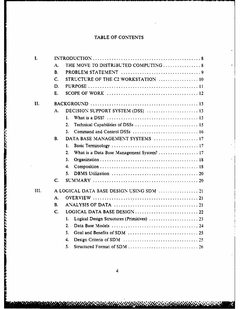
TABLE OF CONTENTS
INTRODUCTION........................................... 8
A. THE MOVE TO DISTRIBUTED COMPUTING ............... 8
B. PROBLEM STATEMENT................................ 9
C. STRUCTURE OF THE C2 WORKSTATION ................. 10
D. PURPOSE............................................ 11E. SCOPE OF WORK..................................... 12
I. BACKGROUND........................................... 13A. DECISION SUPPORT SYSTEM (DSS) ..................... 13
I. What is a DSS? .................................... 13
2. Technical Capabilities of DSSs .......................... 15
3. Command and Control DSSs ........................... 16B. DATA BASE MVANAGEMENT SYSTEMS ................... 17
1. Basic Terminology .................................. 172. What is a Data Base Management System?'................17
3. Organization....................................... 184. Composition ....................................... 18
5. DBMS Utilization .................................. 20
C. SUMMARY.......................................... 20
II. A LOGICAL DATA BASE DESIGN USING SDM ................. 21
A. OVERVIEW.......................................... 21
B. ANALYSIS OFODATA.................................. 21
C. LOGICAL DATA BASE DESIGN......................... 22
1. Logical Design Structures (Primitives) ................... 2 32. Data Base Models .................................. 24
3. Goal and Benefits of SDM............................ 254. Design Criteria of SDM.............................. 1
5. Structured Format of SDM............................ 26
4

D. S I TION QF THE SDM SCHEMA FOR THE C2WORKSTATIO ..................................... 28
E. D ESJRIPTION OF SDM ENTITY CLASSACTVEUNITS ...................................... 29
F. SUMMARY .......................................... 31
IV. A RELATIONAL DATA BASE DESIGN USING ORACLE ......... 33A. METHODOLOGY OF A RELATIONAL DATA BASE
DESIGN............................................. 33
1. Terminology ....................................... 33
2. Design Criteria ..................................... 34
3. Components and Format............................. 34
B. A RELATIONAL DATA BASE DESIGN FOR THE C2WORKSTATION ...................................... 36I. Description of the System Used by NOSC ................. 36
2. Implementation Requirements for the NPS DBMS .......... 363. Design Requirements to Assure Real Time Data Access ....... 37
4. Relational DBMS for the C2 Workstation................. 38
5. Sample Data Base Queries............................ 46
C. SUMMARY .......................................... 49
V. SUMMARY............................................... 51
A. REVIEW OF THE PROBLEM ........................... 5
B. CONCLUSIONS ...................................... 51
C. RECOMMENDATIONS ................................ 52
D. RECOMMENDATIONS FOR FURTHER STUDY ............ 52
E. POTENTIAL PROBLEM AREAS......................... 5
APPENDIX A: SUN WORKSTATION ............................... 5
1. SYSTEM HARDWARE................................. 552. SYSTEM SOFTWARE.................................. 55
a. UNIX............................................ 56b. Window Utility ..................................... 56
c. Mail Utility........................................ 57
APPENDIX B: ORACLE A RELATIONAL DATA BASEMANAGLMENT SYSTEM............................ 58
5

APPENDIX C: RESA BLACKBOARD DATA .......................... 60
APPENDIX D: SA~ p P ~ FRTEDS
LIST OF REFERENCES............................................. 72
INITIAL DISTRIBUTION LIST ...................................... 74
6

LIST OF FIGURES
1.1 Concept of a C2 workstation as a DSS.............................1I1
2.1 Component modules of a DSS ................................... 14
2.2 Realms of a data base management system.......................... 19
3.1 Example of primitive fact ....................................... 23
3.2 Equivalencies between real world and conceptual primitives ............. 24
3.3 SDM format of entity class description............................. 26
3.4 SDM entity class ACTIVEUNITS ............................... 30
4.1 Format for relations ........................................... 35
4.2 Format for domains and attribute!/domain correspondences..............35
4.3 Format for interrelation constraints ............................... 36
4.4 Relation REMOTEDETECTION................................ 38
4.5 Relation ACTIVyE-UNIT........................................3)9
4.6 Relation TRUE-POSITION ..................................... 39
4.7 Relation DYNAMIC INFORMATION............................ 40
4.8 Relation INFLICTED-DAMAGE................................ 41
4.9 Relation ENGAGEMENT DATA................................ 42
4.10 Domains of relational attributes .................................. 43
4.11 Attribute,,Domain correspondences................................ 44
4.12 Player SQL sample I........................................... 47
4. 13 Player SQL query number 2, (subquery)............................ 48
4.14 Analyst SQL query sample, (JOIN)................................ 49
B.1I SQL sample query............................................. 59
C. I Engagement data..............................................60
C.2 Data on ship dynamics ......................................... 61
C.3 Platform unit data............................................. 61
CA4 Position data................................................. 61
C.5 Remote detection data ......................................... 62
C.6 U~nit damage data............................................. 62
D.lI SDM for the C1. workstation.....................................3
7
I. INTRODUCTION
A. THE MOVE TO DISTRIBUTED COMPUTINGOver the past 15 to 20 years there has been a continuous and steady increase in
the development of distributed computer systems. It is generally agreed this was made
possible due to the recent advances in very large scale integration technology and thedevelopment of effective communications over local and wide area networks. It is now
possible to purchase computer systems, which outperform the mainframes of the 1960's
for just a fraction of their original cost.
Although technology made distributed computing possible, it is the people and
organizations that need the system and service it provides. As organizations expand,they tend to become decentralized. Distributed computing is extremely well suited to
companies exhibiting this structure. Distributed computing represents a more natural
realization then a system built around a single large processor because it provides theorganization functional separability and a nonuniform distribution of the database
r.., [Ref. 1: p. 24]. In addition, it potentially offers the user increased reliability, resourcesharing, extensibility, and overall better performance. [Ref. 2: pp. 141-1421
This move towards distributed computing may be interpreted that service to theuser is becoming more important than hardware utilization. [Ref. 1: p. 38]. Mostpeople are not familiar with computer hardware and software. Their only real interest
is in using the computer as a tool in the performance of their job. How useful the tool
is depends on the capabilities of the system and processors available. [Ref. 3: p. 381Todays high performance. 16-bit microprocessors come close to achieving the
performance of minicomputers. In comparison to general purpose microprocessors they
have vastly improved memory space, the ability to handle a greater variety of data,powerful arithmetic capabilities, and increased speed of operation. With suchcapability, operating systems are being designed to run on microprocessors to provide
the user with graphic displays, digitized voice, windowing capability, electronic-mail.and many other features. Microprocessors that can support these features, or some
combination, are sometimes referred to as multimedia workstations. It is this type ofworkstation the Navy is trying to develop to enhance existing command and control
(C2) systems. [Refs. -15: pp. 1, 11]
8

B. PROBLEM STATEMENT
Demands on current Navy C2 systems are constantly increasing due to the
continuing advances in technology; weapons, surveillance and detection systems. This
in turn increases the amount and variety of data C2 systems must handle. How easily
this data is accessed, how quickly, and the way the data is presented, directly affects
how well the system performs, or more explicitly, how well the C2 system assists the
commander in making a decision.
In order to better support the commander, the man-machine interface on the C2
workstation must be more natural and efficient, readily adaptable to individual users,
and able to support multimedia information. Yet, the Navy's current C2 workstations
only operate with a single system and require specialized training. What they need is a
workstation
flexible enough to work with a wide variety of C2 systems- and adaptable enoughto meet the requirements of a diverse set of users. (with) .... Both voice ahdkeyboard natural language interfaces [Ref. 4: p. 11.
The payoff from such a generic C2 multimedia workstation is a more robust approach
to distributed command and control. [Ref. 4: p. 1]
The Naval Postgraduate School (NPS) is currently investigating the use of a
generic C2 workstation as a Decision Support System to aid players of the Research,
Evaluation, and Systems Analysis (RESA) facility [Ref. 6: p. 1]. This is part of the
Office of Naval Technology program NO2CRC32SlO which is a research program in
distributed command and control. RESA is a computer-based. large-scale wargame
simulation of the Naval warfare environment [Ref. 7: p. 1.61. It focuses on battle
group-force level operations and command and control decision making. The Naval
Ocean Systems Center (NOSC) has chosen the SUN microsystems' version of the
UNIX operating system along with the Relational Data Base Management System
ORACLE to function as the C2 workstation.1 NPS intends to interface this
workstation with the RESA wargame to provide players the capability of real-time data
extraction, via a natural language, in order to enhance their decision making abilities.
'Additional information on the Sun microsystem, UNIX, and ORACLE is
provided in Appendix A and B.
9

This arrangement allows the RESA players, umpires, or analysts, to have access
to organized data at nearly the same time it is generated in the RESA system. Real
time access to data involving the current tactical situation permits players to analyze
this data to improve the quality of their next decision or action in the wargame. It
should help players favorably control the outcome of events by reducing the number of
bad decisions. Data made available by this system allows umpires to identify trends,
preclude misapplication of gaming rules, and in the process to better control the game.
In the analysis phase, this workstation provides data which has been obtained in
several wargame scenarios to research problems on individual components or weapon
systems, and to study command and control relationships in Naval and Joint Tactical
Operations.
Installing this workstation is only the first step in NPS's program. There are
plans to interface existing HP 9020 workstations onto the Sun,,RESA local area
network to allow additional users to access the wargame data base and to function as
independent command nodes. The long term goal at NPS is to access the Defense Data
Network (DDN) and provide connectivity to the RESA facility located at NOSC. San
* Diego, Ca. This connectivity will allow the study of a class of C2 problems concerningcoordination at the headquarters level. In the Navy context, this allows researchers to
study problems associated with ship-to-ship distributed command and control and to
apply large computing systems to these problems in real time.
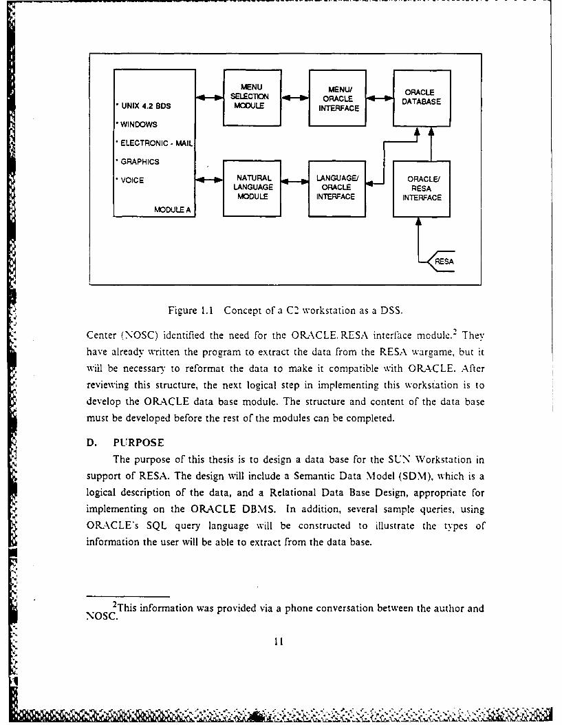
C. STRUCTURE OF THE C2 WORKSTATION
The overall structure of the workstation is shown in Figure 1.1 and depicts the
basic modules required to interface the workstation with the wargame, access the data
base, and prcvide the desired natural language interfaces. Module A is the only part of
the system that presently exists except for the voice interface. This is being built at
Standford Research Institute, Incorporated. The menu selection module is a proposed
interim solution until a sufficient natural language module can be designed for the
system. This would allow the user to interact with the computer by using the same
language structure as when talking to another person. However. true natural language
systems are still in their infancy. They require high levels of vocabulary and syntax
flexibility, while menu-based systems require less computer memory and appear to be
well suited for command and control queries [Ref. 81. The Naval Ocean Systems
* 10
U
MENU MENU/ ORACLESELECTION - ORACLE DATABASE
" UNIX 4.2 BDS MODULE INTERFACE
* WINDOWS
" ELECTRONIC - MAIL
" GRAPHICSVOICE NATURAL LANGUAGE/
LANGUAGE ORACLE RSMODU LE INTERFACE ITRACE
MVDULEA
.4E
Figure 1.1 Concept of a C2 workstation as a DSS.
Center (NOSC) identified the need for the ORACLE, RESA interface module.2 Theyhave already written the program to extract the data from the RESA wargame, but itwill be necessary to reformat the data to make it compatible with ORACLE. Afterreviewing this structure, the next logical step in implementing this workstation is todevelop the ORACLE data base module. The structure and content of the data base
must be developed before the rest of the modules can be completed.
D. PURPOSE
The purpose of this thesis is to design a data base for the SUN Workstation insupport of RESA. The design will include a Semantic Data Model (SDM), which is alogical description of the data, and a Relational Data Base Design, appropriate forimplementing on the ORACLE DBMS. In addition, several sample queries, usingORACLE's SQL query language will be constructed to illustrate the types ofinformation the user will be able to extract from the data base.
2This information was provided via a phone conversation between the author andNOSC.
"- i t
E. SCOPE OF WORK
The thesis is structured as follows. Chapter 1I describes the components of a
Decision Support System and a Data Base Management System and how they can be
used to support C2 systems. Data base processing is the main focus of Chapter IIIand IV. Chapter III describes the terminology and procedures used to create a
Semantic Data Model (SDM). The purpose, characteristics and benefits of the SDM
are discussed in detail. The SDM is created for the C2 workstation using data received
from the Naval Ocean Systems Center in San Diego, CA. A portion of this schema is
described to illustrate the concepts of SDM. Chapter IV identifies characteristics of a
Relational Data Base Design, its format and then describes the relational design
developed for the C2 workstation. Sample queries on the data base are provided at theend of Chapter IV in order to tie both the SDM and relational data base design
together. This is followed by recommendations and conclusions for continued work in
this area. Appendices contain information on the Sun Workstation, ORACLE DBMS,
the data provided by NOSC, and the complete Semantic Data Model for the C2workstation. This work does not include implementing the relational data base design
using ORACLE.
:1
r12

I1. BACKGROUND
Chapter II provides' background information on the structure of Decision
Support Systems and Data Base Management Systems. It defines both of these systems
and describes their individual components, characteristics, and capabilities. In addition.
Decision Support Systems are described in relation to their potential to improve the
current comand and control decision-making process.
A. DECISION SUPPORT SYSTEM (DSS)
1. What is a DSS?
As previously mentioned, the Navy is developing a C2 workstation as a
Decision Support System to aid players of the RESA war game. Such a system
provides the potential for players to use information by filtering, analyzing data, and
comparing alternatives [Ref. 9: p. 91. It will help them make decisions concerning their
next move in the game by considering "what if' situations. This is exactly what a DSS
is supposed to do.
a. Definition
A DSS is a computer-based, online, interactive system that helps
commanders make key decisions, thereby improving the effectiveness of their problem
solving process. It incorporates the experience and instinct of the decision-maker to
analyze hypothetical questions before implementing an irrevocable decision.
[Refs. 10,11: pp. 24, 4]
b. Components of a DSS
DSSs are characterized as localized, autonomous systems containing
analytical modules having free access to information. They generally consist of a data
base management system (DBMS), report generator, a data base query language,
graphics package, and special-purpose software (Ref. 10: p. 24]. Conceptually, this
breaks down into four basic modules (Figure 2.1): [Ref. i1: pp. 10-131
1. Control - this is the user-interface or front-end of the svstem. It is usually menu-driven with keyboard inputs and interfaces with the other three modules. Itprovides promots and messages to guide the user in formatting the problem andgenerating a response.
2. Data storage - contains all data required by the DSS.3. Data manipulation - this is responsible tor retrieving data from the data storage
module and producing reports or graphs using th data. It is supported by-anonprocedural query language normally provided by the DBMS.-
13
.9 9!1* 9*-'%

4. Pfodel-b.uilding -. utilizes optimizing modeling principles, statistical analysis,-orecasting a gorithms, decision analysis methods, and simulation principles formodeling and simulation purposes.
These four modules must also display certain characteristics to be considered a true
DSS.
DATAMAMPULATI NI
MODO-ULDOU DATA STOPAWMODULE MOOLU
MOOLL! ?WMOLA.E
CRT
USER INPUT
Figure 2.1 Component modules of a DSS.
c. CharacteristicsGenerally speaking, a particular system is only considered a DSS if it
provides interactive support for the thought processes of one or more decision- makers.
Systems used in this way must exhibit certain characteristics. Among these are:
[Refs. 12,13: pp. 15, 77-7811. Flexibilty - a DSS must accommodate and support decisions, under highly
varying conditions, on an 'ad-hoc" basis.2. User-fiendliness - the system is typically designed for a user unfamiliar with
computers. If necessary, it can guide uscr in opcrating the system.
3. Natural language capability - DSSs must communicate in terms fandliar to theuser.
4. Timeliness - speed of response is necessary to maintain continuity of the user'sown thought processes.
5. Enhanced decision-making - a DSS must exhibit a structure which isunderstood by the user and" reflects his own way of thinking.
14
------ ---------

6. DSS must be evolutiona - the system must evolve, grow and be easily and
quickly modified to meet c anging circumstances.
These characteristics are the ideals or norms of the DSS concept. They are necessary
for handling a variety of problems a decision-maker may encounter.
2. Technical Capabilities of DSSs
a. FunctionsThe primary function of a DSS is to assist decision makers in solving "what
if' type questions. These consist of unstructured or semi-structured problems related to
strategic planning, management or operational control [Ref. 14: p. 8]. Unstructured
problems are those activities in which the solution objectives are ambiguous,
numerous, and the process required to achieve a solution cannot be specified inadvance. It is an activity involving a decision process which is partly routine and
partly judgmental. Whereas the routine part can be automated in a computer program,
the judgmental aspect is the responsibility of the decision-maker. [Refs. 11,12: pp. 7,
151
Goal seeking is another major contribution offered by a DSS. Byassembling appropriate analytical and simulation models on the system, the decision-
maker can pick a desired goal. The DSS then seeks the optimal decision path or set of
solutions to arrive at the specified outcome. [Ref. 10: p. 251
DSSs also perform two other functions for the decision-maker. First, itallows users to manage very large data bases, where the manager may have difficulty in
accessing and making conceptual use of all the information.
Determinin' where to look for a particular piece of information is a nontrivialissue. Actuaulv retrieving it can be a substantial task which complicates and slowsthe process of command decision [Ref. 15: p. 291.
DSSs reduces this problem by offering real-time data extraction and data manipulation
or computation in order to arrive at a solution or suggested alternative. The secondfunction a DSS provides is the ability to handle time-sensitive issues. These issues are
especially common on the battlefield. As new technology is introduced to the
battlefield, the critical response times required for decisions grow shorter at all levels ofthe command hierarchy. The human elements of the system are not able to respond
fast enough and require some form of automation to assist in their analysis of data and
other environmental factors. [Ref. 15: p. 2S] DSSs provide this capability and offier the
15
commander the opportunity to review the problem and choose an acceptable solutionin time to meet the immediate threat. DSSs provide this automation for the decision-
maker, thereby reducing the time required to make a decision. [Ref. 11: p. 7]
b. Levels of Support
There are four levels of support available from a DSS [Ref. 11: p. 91. Theseareas were briefly discussed throughout the beginning of this chapter and are
summarized here as part of the capabilities provided by the system. They are:
1. Access to facts or information retrieval.
2. Addition of filters to selectively ask for information and give conceptualmeaning to data.
3. Ability to perform simple computations, comparisons, and projections.
4. Development of useful models designed to provide the decision-maker withanswers they can and will act on.
These functions and capabilities are the reasons why DSS are being developed to assist
command and control (C2) systems.
3. Command and Control DSSs
To understand why DSSs are being used in C2 systems it is necessary to
understand the C2 decision making process. According to Joel S. Lawson, this process
consists of five phases: sense, process, compare, decide, and act. The process, compare,
and decide phase is where a DSS will be able to help improve the present capabilities
of C2 systems. The process function extracts meaning from the signals it receives from
the sensors and then generates event and status reports in its assessment of the
situation. The compare function evaluates the options by comparing the local
environment as seen from the status reports to some other desired state. Based upon
this comparison, the decide functicn then determines what should be done in order to
achieve the desired state or goal. [Ref 16: pp. 24-25]
A DSS is very similiar to the C2 decision making process. The system allows
quick access to facts and information and filters and displays the information in a
representative form (graphics and charts) that give conceptual meaning to the data.
This is like Lawson's process function. The systems ability to assist the decision maker
in solving "what if' type questions is equavilent to Lawson's compare function, while"goal seeking" is more comparable to Lawson's decide function. The advantage
command and control DSS offers the commander is the ability to handle a wide range
of problems under varying time constraints. It is this very need for accurate data. and
fast and timely decisions in a very violatile and uncertain environment that provides
16

the justification for DSSs. [Ref. 14: p. 11] However, in order for a DSS to provide the
commander non-routine information through 'ad-hoc" queries, the system must have a
suitable data base management system [Ref. 11: p. 6].
B. DATA BASE MANAGEMENT SYSTEMS
1. Basic Terminology
In order to discuss a Data Base Management System (DBMS) it is necessary
to define some basic terms and concepts: A Data item, which is also called a field or
attribute, is a group of non-random symbols that represent quantities, actions, things.
facts, concepts or instructions. A File is a collection of related records and a Data Base
is a collection of files logically related in such a way as to improve access to data. A
Data Base Management System is a software system capable of supporting and
managing an integrated data base. Finally, a Conceptual Model or data model is a
logical representation of the information (data that has been processed and presented)
contained in the data base. [Refs. 17.18: pp. 5, 3]
2. What is a Data Base Management System?
a. Definition
A data base management system is a complex, usually large program that
acts as a data librarian which stores and retrieves data from a data base [Ref. 19: p. 31.
Its most attractive feature is its collection of integrated, shareable. and nonredundant
data. An integrated data base brings together a variety of data which can be accessed
by more than one user. This ability to share data keeps the amount of redundant
storage to a minimum. [Ref. 17: p. 51 Simply put, a DBMS is software consisting of a
set of tools or features to manipulate and support the data base. The fundamental
features provided by a DBMS are: [Ref. IS: p. 4]
1. Centralized control of the data, which implies reduction of data redundancy,shared data, protection of the data base integrity, and enforcement of standards.
2. Data independence: the ability to modify the data base structure withouthaving to modify the programs wlich use the data.3. Provision for complex file structures and access paths., such that relevantrelationships between Uata units can be expressed in a natural form.
4. Generalized facilities for storage, modification, reorganization, analysis andretrieval of data. This is done with programming languages, a user querylanguage or both.
5. Security to prevent unauthorized access to stored data.
6. Mechanisms to enable easy recovery or restoration of the data base.
17
4 6

3. OrganizationThe data base organization can be visualized as three separate realms, as seen
in Figure 2.2 [Ref. 17: pp.16-1 7]. The conceptual level is independent of computer
hardware. It is a picture of the data base as visualized by the user of the DBMS. There
are currently three main types of conceptual data base models available. They are:
[Ref. 19: pp. 117. 120, 196]
1. Hierarchic - the structure is in the form of a tree with a one-to-manyrelationship among records. An individual record (node) may only have oniowner (parent). It is a subset of network.
2. Network - is a collection of records exhibiting either a one-to-many or many-to-many relationship among records. An individual record may hav'e more thanone parent.
3. Relational - represented in the format of a table called a relation. Rows of thetable are file records or tuples and fields of the relations are shown in thecolumns called attributes.
These models describe the structure and processing of the data base.
The logical level is the equivalent model of the user's view of the data but it is
organized in accordance with a particular data base system model. ie. hierarchy,
inverted hierarchy, network or relational DBMS. The final level is the physical data
base structure realm which represents all data definition directories, access paths and
methods, and the actual data itself.
4. Composition
The actual composition of a DBMS depends on the vendor. Larger computers
can support more elaborate DBMS providing a greater variety of tools. Smaller
systems, like microcomputers, restrict the size of DBMS and therefore, reduce the
number of tools available. However, there are two major features common to all
DBMS. They are the Data Definition Language (DDL) and the Data Manipulation
Language (DML). [Ref. 19: p. 1911
DDL is a vocabulary for describing the "schema" and "subschema." The
schema is the description of the complete logical data base, and the subschema is the
description of a subset of that data base used by an individual computer program. The
DDL includes terms for defining records, fields, keys, and relationships. It should also
provide the means to express a variety of user views and data base constraints.
[Ref 18: p. 5]
The DML is a vocabulary for describing the processes (retrieving or changing)
that can be performed on the data in the data base. There are two types of DML:
procedural and nonprocedural. Procedural DMLs use high level prograrmmng
18

CompanyiflofmJitofl
CnvpIujI~
of cornruter Mp) cc~p~~aspet. h 8flhrmJitin
/ - Cjnirini
,vtL' ~ r, 1.qv!J
it .,'m ul r d.I flia
gurjix~~,1:1 J1nj~tnc~:g
%truKire
Tapes RanJum i~es itordpt Jcvwes
Figure 2.2 Realms of a data base management system.
languages (such as COBOL and FORTRAN) to access the data base. They describe
explicitly the actions to be performed on the data base. Nonprocedural DMLs simply
19

state-what is wanted but not how to obtain it. Nonprocedural DMLs are directed
towards noncomputer specialists.
5. DBMS Utilization
Data base management systems are valuable wherever there is a requirement
to manage an integrated data base. Continuing advances in computers have resulted in
sirniliar advances in DBMS. They now operate on microcomputers and workstations as
well as the large mainframe computer systems. DBMS are used in business
applications, the military (such as wargaming and decision support systems), and in
research facilities. All three of these areas share the identical problem of trying to
manage vast amounts of data in a timely and effective manner. NPS has chosen
ORACLE as the relational DBMS for their DSS C2 workstation. Representative data
created during play of wargaming scenarios and provided by NOSC, will be utilized as
a surrogate for actual operational data. This data provides a wide spectrum of process
records for the analyst and system designer alike.
C. SUMMARY
Chapter II defined DSSs as a computer-based. interactive system that
incorporated the experience and instinct of the decision-maker to analyze hypothetical,
"what if' type questions. These systems require flexibility, user-friendliness, a natural
language capability, timeliness, and evolutionary characteristics. The advantage that a
DSS offers to the commander is the ability to improve the process, compare, and
decide phases of the command and control decision-making process. In order for a
DSS to support 'ad hoc" queries from the user, a suitable data base management
system is required. A DBMS is defined as a complex. usually large program which
stores and retrieves data from a data base. Organizationally, the DBMS consists of
three levels; the conceptual (or user's perception of the data base), the logical level
(which defines the user's perceptions in terms of a particular DBMS), and the physical
level (which contains the actual data itself). Specific applications for DBMSs include
wargaing and decision support systems. However, a data base design is required
before any system can be implemented and Chapter III describes the methodolgy used
to design such a logical data base design.
20
& -. '.

III. A LOGICAL DATA BASE DESIGN USING SDM
This chapter describes the procedures and format used to develop the logical data
base for the C2 workstation using a Semantic Data Model. The first section analyzes
the data received from the Naval Ocean Systems Center (NOSC). Then, the basic
structure and models used in the logical data base design are described with particular
attention given to the Semantic Data Model. Specifically, the characteristics. benefits,
purpose, and format of the SDM are discussed. Finally, a narrative description of the
SDM schema developed for the C2 workstation is provided with a detailed explanation
of one of its entity classes.
A. OVERVIEW
What actually constitutes a data base design varies from author to author and
certain areas tend to overlap. We will use the method suggested by David Korenke in
his book Data Base Processing [Ref. 191. According to Kroenke. data base design is a
two-phased process consisting of a logical data base and a physical design. First. the
user's requirements are examined and a conceptual data base structure is created to
model their organization. This is called the logical data base design. In our case the
logical design is represented using the SDM. Once this design is complete. it is
formatted in terms of a particular DBMS. In our case this is a relational DBMS since*s ORACLE is the chosen DBMS for the workstation. This second step is called the
physical data base design.
Data base desien is an intuitive and artistic process. There is no algorithm for it.
[Ref. 19: p. 1771 It is an interactive process with the goal to get closer to an acceptable
design. The data base is a bridge between people and hardware and the designer must
consider both these characteristics. The logical design specifies the needs of the people.
The physical design maps the logical design into constraints of a particular program
and hardware products. "The goal when developing a data base design is to make only
uninteresting questions unanswerable." [Ref. 19: p. 206]
B. ANALYSIS OF DATA
The data used in this design was supplied by NOSC in San Diego. Ca. NOSC
wrote the computer program to extract this data lrom the RESA wargiame s
21

blackboard and the data are updated once every minute of game play. The data are run
through a TAPEPIPE.EXEC computer program, also supplied by NOSC, which
separates the data into six associated files corresponding to RESA tables. The common
denominators between all files are the game time and associated slot number. These are
control numbers used by the computer program as it extracts the data from the
blackboard. They also serve a secondary purpose, which is to relate the separated data
files to one another. A sample listing of data, their associated fields, and an
explanation of their interrelationships is provided in Appendix C. It is this data that
will be used to develop the logical data base and relational data base design.
C. LOGICAL DATA BASE DESIGN
The logical data base design specifies the logical format of the data base. It is
sometimes called the schema or logical schema. It identifies the records maintained.
their contents and the relationship among the records. The contents of each record
contains field names and their required format. As requirements are evaluated
constraints on data items are identified. There are three types [Ref. 19: p. 179]. Afield
constraint limits the value a given data item may have. Intrarecord constraints limits
values between fields within a record and interrecord constraints limit values between
fields in different records. The level of record detail depends on the designer. There are
few records if the model is highly aggregated and generalized or many records if very
detailed.
In developing the schema the assigning of data items is relatively straightforward
for two-thirds to three-fourths of the record types, but problems do arise. Some of
these files may need to be combined or separated, and if this is done, does it make thedesign more effective? The designer must also allow for growth and anticipate luture
requirements of the user. A final problem encountered concerns "implied" data. This is
an item that is needed to meet a requirement but is not visible to the user. [Ref. 19: p.
1821
The second step in developing the schema is determining the relationships among
the records [Ref. 19: p. 1821. The designer must model how the user sees the
relationships. This is done intuitively, but in designing relationships. the designer must
distinguish between theoretical and useful ones. A theoretical relationship can exist
logically but, in practice, may never be needed. "In general. if there is any question
regarding whether a relationship is useful or not, then the relationship should be
included in the logical schema." [Ref. 19: p. 1861
!22

1. Logical Design Structures (Primitives)
Before it is possible to design files and relationships, it is necessary to
understand the foundations of data modeling. The data base design is only a
representation of reality. It is a model of some activity, a conceptual presentation of
real world structures or primitives. [Ref. 19: p. 2051
Primitives in the real world consist of objects, object classes, properties,
property value sets, facts, and associations. An object is defined as some phenomena
that can be represented by nouns, such as a ship. Object classes (ships) are merely
groups of objects formed by generalizations. Properties are the characteristics of these
objects and the collection of all values a property can have is called the property value
set. The intersection of a given object with a given property value set is called a fact.
This concept is illustrated in Figure 3.1. Finally. an association is the connection of
objects of the same or different classes and they may also have properties. [Ret. 19: p.
207]
HEIGHT PROPERTYVALUE SET
FACT
RAY HARRIS 67 INCHES 27 YEARS OLD BASKETRALL SKILL
OJECT 77 INCHES74 INCHES59 INCHES
Figure 3.1 Example of primitive fact.
Only a representation of these real world primitives is used in designing a data
base. A 74 inch person can be inserted into a car or ship, but not into a data base.
Therefore, data base experts have defined a conceptual primitive for each of the real
world primitives. They are entity, entity classes, attributes, domain (which is the
collection of all values an attribute can have), a value (which is the intersection of a
23

given entity with a given domain), and a relationship. The equivalences between real
world and conceptual primitives is depicted in Figure 3.2 [Ref. 19: p. 209]. These
Real World Primitive Conceptual Primitive
Object EntityObject Class Entitv ClassProperty AttributePropertr Value Set DomainFact ValueAssociation Relationship
Figure 3.2 Equivalencies between real world and conceptual primitives.
conceptual primitives will be used in the development of the logical data base design.
2. Data Base Models
All data bases are a model of some system in the real world. The actual data
represents events, frozen in time, that occurred in the application environment. Any
change to the data base should only occur if a similiar change occurred in the
environment. This means the structure of the data base should "mirror" the structure of
the system it models. It is easier for the data base designer to build and modify the
data base when it is based on naturally occurring structures in the environment. This
same rationale can be applied to the data base user. If data bases are described in
terms and concepts familiar to the user, then it should become easier to understand
and employ the data base. [Ref. 20: pp. 351-352]
A data base model is defined as a logical schema "specified in terms of a
particular data base description and structuring formalism and associated operations."
[Ref. 20: p. 352] These models are important tools for designing both logical and
physical data bases. There are many useful models available, such as the Entity-
Relationship model, the Relational Data model, and the CODASYL DBTG model.
They range from being human-oriented on one side to machine-oriented on the other.
All these models have one thing in common; they describe the structure and processing
of a data base.
The Semantic Data Model (SDM), as developed by Hammer and McLeod and
first published in 1981 [Ref. 201, will be used for the development of the logical data
base design. This model is human oriented, and because of its semantic nature, SDM
24

is recommended for logical data base design. Hammer and McLeod do not believe thedata structures provided by contemporary data base models, such as those listed above,adequately support the design, evolution, and use of complex data bases. They aresignificantly limited in their capability to express the meaning of the data base to its
corresponding application environment.
The semantics of a data base defined in terms of these mechanisms are notreadily apparent from the schema: instead the semantics must be separateivspeced ov the data base designer and consciously applied by the userS[Ret. 20: p. 3521.
We believe that SDM provides better facilities (than models like the Relational Data
Model or the Entity-Relationship Model) for expressing meaning about data, avoidingconfusion, and documenting design decisions and constraints [Ref. 19: p. 1941].
3. Goal and Benefits of SDNIThe goal of SDM is to enable the data base designer to directly incorporate
more meaning and relationship about the data into the logical schema. It serves as amodeling mechanism to express the natural structure of the environment :n :hestructure of the data base design. SDM provides several benefits to the user. First. it isa formal technique to describe meaning about the data base. It provides prec:sedocumentation of the data and it is a-communication medium which allows the user todetermine what information is contained in the data base. Second. SDNI allows the
construction of user interfaces to the data base which improves the process ofidentifying and retrieving relevant information. These can be front-ends to existing database management systems (DBMS) or query languages for new DBMSs. An additionalbenefit of SDM is it supports effective and structured design of data bases.
[Ref. 20: pp. 352-3531
4. Design Criteria of SDMThe Semantic Data Model was developed by Hammer and McLeod to meet a
number of criteria not met by the contemporary data base models. They felt the database should be designed to provide specific meaning to a large portion of the data base.In addition, it should support a view related to the meaning of the data base and have
a structure which supports different ways of viewing the same information. Thisrequires a data base model be
1. Flexible - allow for multiple and coequal views of data
25A.t

2. Logically redundant - values of components can be derived from othercomponents in the data base
3. Integrated - this describes the relationships of a data item viewed in differentways
The last essential criteria for SDM is it must be able to describe relevant entities
(which represent objects in the real world environment), groups of these entities, their
relationships, and the interrelationships among the groups. [Ref. 20: pp. 353-354]
5. Structured Format of SDMWe 'ill now discuss the SDM format which is displayed in Figure 3.3
[Ref. 19: p. 213]. A data base is viewed as a collection of entities that correspond to
ENTITYCLASS-NA MEdescription: ------- .......-------------------interclass connection: --------------------member attributes:
Attribute namevalue class: ------------------
mandatorymultivalued. no overlap in valuesexhausts value classnot changeableinverse: Attribute namematch: Attribute -hame of ENTITYCLASS
on Att-ibute name2derivation:--
class attributes:
Attribute-name
description: -----------------value class: -----------------
derivation: ------------------identifiers:
Attributenamel + (Attribute name2 +
Figure 3.3 SDM format of entity class description.
the actual objects in the application environment. These entities are organized into
classes that are meaningful collections of entities. The class name identifies the class of'entities and must be unique with respect to all other class names in the schema. The
description defines the purpose and content of the class. It describes the specific nature
26

of the entities and indicates their significance and role in the application environment.
[Ref. 20: pp. 355-356]
The class is composed of a collection of members or entities. These entitiescorrespond to various kinds of objects in the application environment such as concrete
objects, events, categorizations or syntactic identifiers (STRINGS). STRINGS are any
character string which the designer wants. There are two types of attributes whichdescribe the members of the class or the class as a whole: a member attribute or class
attribute. The member attribute describes an aspect of each member of a class by
logically connecting the member to one or more related entities in the same or anotherclass. The class attribute describes the property of a class as a whole and not any
particular member. [Ref. 20: pp. 356-357]
A class can either be a base class or a nonbase class. A base class is definedindependently of all other classes whereas a nonbase class does not have an
independent existence, but is defined in terms of one or more other classes. These
nonbase classes are related by means of an interclass connection which describes howthe class is constructed. There are two types; a subclass connection is a class that
' contains some but not necessarily all of the members of another class and the groupingconnection has members that may themselves be viewed as classes. [Ref. 20: pp.
357-358]
Data base entities and classes have attributes that describe their characteristicsand relate them to other entities. These member attributes have value classes whichmay be an entity in the data base or a collection of such entities. The value class
contains the permissible values of that attribute and may be derived from other values
in the data base. There may or may not be constraints and relationships on member
attributes. If any, they are defined as follows.
1. multivalued- this is like a repeating field, there is more than one. For example aship may be described as a particular type such as a destroyer. This would beconsidered singlevalued since it can not-be defined as any other type. Howeverthis same ship may have many kinds of weapon systems. Therefore weapons, itlisted as a member attribute would be multivalued.
2. Mandatory - the null value is never accepted. Type from the previous examplecan be thou2ht of as a mandatory constraint. EVery ship must be described bytype, cruiser'or destroyer, whenever it is listed in thi data base.
3. Not changeable - the value of an attribute must remain the same. This meansthe value, once set, cannot be changed except to correct an error. If the type ofship listed was wrong, then the valie can be changed.
4. Exhaustive - every member of the value class must be used. For example. ifengines were listed as a member attribute ot an entity class called SIIPS. thenevery engine entity listed must be an engine on some ihip.
27
..-

5. Non overlapping - a member of the value class can be used at most once or notat all. It the engine of the entity class SHIPS were specified as non-overlapping,then this means that any engine listed can be in only one ship.
6. Inverse - this causes two entities to be contained in each other. For example, iftwo entity classes were defined as PITCHERS and RECIPES then these wouldbe inverses if a member attribute from each entity class had a value class listedas PITCHERS and RECIPES. Let us assume that kind of recipe used is amember attribute of PITCHER and its value class is RECrPES. andpitcher reci e used in has a value class of PITCHERS. These then areconsidEred obe irerse of each other.
7. Matchin. - a member of one entity class is matched with a member of anotherentity crass. This means the valub o" an attribute in one of the members ismovd to the other member in another ejntity class. As an example, let SHIPSand ASSIGNMENTS be defined as entitv classes with member attributes ofCaptain and Ofiicer respectively. If' Captain is matched to Officer ofASSIA N".\.ENTS then the value' of Captain is determined by the value ofOfficer from ASSIGNMENTS for a particular ship.
8. Derivations - these are statements clarifying how to derive an attribute. Theycan also be used to specify relationships among members in the same entityclass. An example is a cliss attribute of total number of ships. This is thefiderived by summ-fing the total number of ships lis-fed in tl~eeChtity class SHIPS.
Finally, the identifiers are unique keys which identify individual records. This is theformat used to develop the SDM schema described in the next section and Appendix
D. [Refs. 19,20: pp. 213-224, 363-365]
D. DESCRIPTION OF THE SDM SCHEMA FOR THE C2 WORKSTATIONThe identification of the data extracted from zhe RESA wargame has already
been completed by the Naval Ocean Systems Center (NOSC). We transcribe the data
into an SDM schema and tailor it to meet the needs of NPS, occasionally deletingcertain items which seemed to have no real value to the user.3 The information in this
process was obtained from the blackboard in the RESA data base, while constraints on
the data were identified by evaluating the sample output data supplied by NOSC. The
data are broken down into six basic areas or entity classes based on the type of
information available to the user. These classes are:
1. Active units- this describes all units, whether hostile or friendly, which areparticipating in the wargame scenario. Units can be ships, shore bases, aircraft,submaines or cruise missiles.
2. Remote detections- contains the apparent latitude and longitudinal position of alldetected targets such as aircraft or cruise missiles.
3. True position- this entity class provides ground-true latitude and longitudinalposition for each active (init in the game.
4. Inflicted damages- identifies what unit was damaged, the time it occurred, andwhich eeneral" areas sustained damage. For example. it will indicate if a ship issinking'or its maximum speed possible after being damaged.
3Those items deleted were discussed with personnel at NOSC to confirm theirintended use in the data base.
28:!

5. Pynamic infermation - contains specific information for each active unit. Itmcludes the percent of damage suffered by a unit and the amount of equipmentremaining after being, damaged. In addition, it provides an acfounting forweapon expenditures aurin& combat operations by Keeping track of the numberof missiles remaining and other similiar items.
6. Engagement data- provides information on aircraft and ships engaged in combatoperations. It includes calculated probabilities on a.ircraft air-to-air missilestrikes and on ship launched nissiles for interception of inconing cruisemissiles. It defines the current position of both the attacking unit and targetand the status of the target after the engagement i.e., whether it was hit ordestroyed.
E. DESCRIPTION OF SDM ENTITY CLASS ACTIVEUNITSIt should be noted that certain formats in the domains of the value classes listed
in this schema were changed from those originally specified in the RESA blackboard.
This was done to accommodate the players of the wargame, since this workstation will
also be used as a DSS to interact with the game on a real time basis.4 For example, itwill be much easier to read the name of an item than trying to interpret what a
particular number is supposed to mean, especially when the range of possible totalvalues exceeds ten. Since this workstation is supposed to assist the decision-maker we
felt it was necessary to make these changes. The entity class ACTIVE_UNITS is
shown in Figure 3.4 to illustrate the SDM concepts discussed in this chapter. The
complete SDM schema is listed in Appendix D.
ACTIVEUNITS describes those units which are participating in the war
scenario. The member attributes for each specific unit are Name, Status, View, Type,
Assigned target-of unit, Bombhits, and Missile-hits. The unique identifier for thisentity class is Name since no two names within ACTIVEUNITS are the same. The
member attribute Name has a value class of UNIT NAMES. This is a subclass of
STRINGS having a maximum length of eight characters which identifies the name of
each unit. It is considered mandatory., along with member attributes Status, View. and
Type because these are the minimal members that must be contained in the entity class.
If there is no Name then no other information should be provided. If there is a Namethen the minimum information needed for each unit are Status, which describes the
present condition of the unit, View. which identifies the unit as hostile, friendly or
neutral, and Type, which identifies whether the unit is a ship, submarine or aircraft.
The value class of Status is UNIT STATUS which is a subclass of STRINGS whose
format is an integer from 0 to 10. For example, 0 indicates if the unit is being deleted. 2if the unit is on station and 3 if the unit is proceeding. View has a value class equal to
4 NOSC only uses their workstation for post game analysis.
29
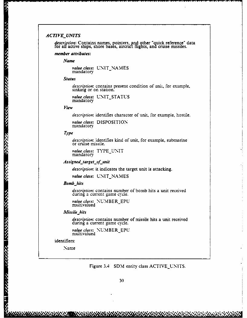
ACTIVEJUNITS
description: Contains names, pointers, and other "quick. reference" datafor all active ships, shore bases, aircraft flights, and cruise missiles.
member attributes:
Name
value class: UNITNAMESmandatory
Status
description: contains present condition of unit, for example.sinkirg or on station.value class: UNIT STATUSmandatory-
View
description: identifies character of unit, for example, hostile.value class: DISPOSITIONmandatory
Type
description: identifies kind of unit, for example, submarineor cruise missile.value class: TYPE UNITmandatory
Assignedtargetofunitdescription: it indicates the target unit is attacking.value class: UNITNAMES
Bomb hitsdescription: contains number of bomb hits a unit receivedduring a current game cycle.value class: NUMBEREPUmultivalued
Missile hitsdescription: contains number of missile hits a unit receivedduring a current game cycle.value class: NUMBER EPUmultivalued
identifiers:Name
Figure 3.4 SDM entity class ACTIVEUNITS.
30

DISPOSITION. This is a subclass of STRINGS whose format is an- integer from 0 to
10. In this case a 1 indicates the unit is neutral, a 2 if friendly, and 3 if hostile. Thevalue class Type is TYPEUNIT. This is another subclass of STRINGS whose format
is an integer from 0 to 10. Examples of these values are: I identifies the unit as an
aircraft, 5 identifies a cruise missile and 4 indicates an aircraft carrier.
Assigned target of unit identifies which target the unit is currently attacking such as anaircraft or cruise missile. There is no mandatory value for this member attribute since
it can assume a null value. There are times when a ship may not be engaged in combat
operations. Its value class is UNIT NAMES. Bombhits and Missilehits are member
attributes that are considered multivalued attributes. An individual unit can receive
more then one hit by a bomb or be hit by more then one missile. They share the samevalue class NUMBER EPU. This identifies the number of explosive power units
(EPUs) received by a unit. It is a subclass of STRINGS whose format is an inte2er
from 0 to 200. The rest of the entity classes defined in the SDM for the C2 workstation
are contained in Appendix D.
V F. SUMMARY
Chapter III describes the methodology used in the logical data base design. Thisdesign contains the conceptual data base structure which models the user's
requirements for the organization. The Semantic Data Model was used to develop thelogical schema for the C2 workstation based on data received from the Naval Ocean
Systems Center. This model was chosen over existing data base models like theRelational Data Model or EntityRelationship Model because it provides better
facilities to express meaning about the data, avoid confusion and document design
decisions and constraints. SDM is a mechanism to describe the meaning of the data
base. It provides a variety of semantic-based user interfaces to the data base, and it isthe foundation of effective and structured design for data bases. The basic format of
SDM consists of an entity class (a group of entities corresponding to actual objects inthe environment), member attributes (characteristics of the entity class), and a value
class (which are the permissible values an attribute may have).
A narrative description of the SDM developed for the C2 workstation wasprovided in the last section. It was divided into six basic entity classes. The first class
described individual characteristics of all active units in the wargame and was described
in detail in this chapter to illustrate the concept of SDMI. The next two identified
31

apparent and true locations of detected targets and active units respectively. The fourth
entity class identified areas of damage that a unit sustained while the next one
contained specific information on the amount of damage received and expenditure of
resources of a particular unit. The last class described data on units engaged in actual
combat. This schema forms the basis for developing the relational data base design
which is described in Chapter IV.
32

IV. A RELATIONAL DATA BASE DESIGN USING ORACLE
This chapter is divided into two major sections. The first describes the criteria,
components, and format used in developing a relational data base design. The second
section transposes the SDM in Appendix D into a relational data base design for the
C2 workstation. It begins by describing the current system used by NOSC to extract
data from the RESA wargame and to transfer it to their data base management system
(DBMS) on their own workstation. This system is used to identify similiar areas of
work which will be required before NPS can implement their own DBMS. In addition.
this section describes that portion of the design necessary to provide the user the
capability to access the data on a real time basis. Finally, the last part of this section
contains the detailed structure of the relational data base design supported by tables of
data and several sample SQL queries to illustrate ORACLE's data manipulation
language.
A. METHODOLOGY OF A RELATIONAL DATA BASE DESIGN
The physical data base is the second stage of the data base design. The logical
schema (the SDM model) is transformed into the particular data constructs of a
DBMS. This will be a relational data base design compatible with ORACLE and will
produce detailed specifications of the data base structure. These specifications will then
be used during data base implementation to write source statements defining the data
base structure to the DBMS.
1. Terminology
The basic format used in a relational data base design is a two-dimensional
table called a relation. The relation, or flat file, containing single-valued entries, is
constructed of columns and rows of data. The columns are called attributes while rows
are called tuples. No two tuples in a single relation can be identical. All entries in a
column must be of the same kind or category, ie., all ships or all names. These entries
represent possible values for an individual attribute and the range of permissible values
is called a domain. [Ref. 19: p. 243]
The terms relation, attribute, tuple, and domain correspond directly to SDM
terminology. This makes it easier to transpose the SDM schema into a relational data
base design. Entity classes in SDM may be transposed into relations while SDM
33

member attributes are like tuples. Attribute names in SDM are very similiar to
relational attributes or columns and STRINGS value classes in SDM directly
correspond to domains. The distinction in the last case is that tuples are not permitted
to contain other tuples in relations which is allowed in SDM. [Ref. 19: p. 245]
2. Design Criteria
Again, there are no set of rules to follow in all circumstances when creating a
relational data base design, but there are several criteria for producing an effective
design [Ref. 19: p. 307]. The first step is to eliminate any modification anomalies.
These are unexpected consequences that occur when changing data. There are two
general categories:
1. Deletion anomaly - this is the loss of information about two entities with onlyone deletion.
2. Insertion anomaly- this is the g2ain of information about two entities with oneinsertion. Stated "negativelv, it-means information about an entity cannot beinserted until there i additional information about another entity. "
These anomalies can be eliminated by creating two new relations called a projection. A
disadvantage in doing so is that this causes undesirable interrelation constraints since
two relations share the same attribute. It is not always possible to eliminate all
anomalies from a relation, but through the use of "Normal Forms" designers can
attempt to reach this goal. A normal form is a process that classifies an anomaly and
then describes a way to prevent it from happening. Refer to Kroenke's book on Data
Base Processing, Chapter 8, for a detailed explanation of these forms [Ref. 19].
The last two criteria or goals for a relational data base design are relation
independence and ease of use. If a relation can be modified without regard to another
then the relation is independent. Ease of use requires that relation structures he
familiar and seem natural to the user. When all these criteria conflict, as they
sometimes do, then the designer must assess the priorities and make the best possible
compromise.
3. Components and Format
This section defines the three major components of a relational data basedesign; relations, domains and attribute domain correspondences, and interrelation
constraints [Ref. 19: pp. 311-321]. The first component specifies the name, attribute,
and key of the relation. The generalized format is displayed in Figure 4.1. In addition.
the relation table will contain four to five tuples of example values from the domain
associated with each attribute. The order of the values listed will match, one-to-one.
34
II .

RELA TION NAMIE (attribute 1, attribute2, ..
Key(s): relation attribute
Attribl Attrib2 Attrib3 Attrib4 Attrib5 Attrib6
value I value2 [value3 vau4value5 value6value2 ____________ __
value3
value4
_______________ _________________ ________________ ________________ ______L _________
Figure 4.1 Format for relations.
the order of the listed attributes. Each defined relation will be listed in separate figures
compared to only one Figure for the remaining components. The second component
specifies domains and attribute,, domain correspondences for the entire relational data
base design. Domains are defined both physically and semantically because it Is
possible that two domains will have the same appearance but have very different
meanings. The structure for this component is depicted in Figure 4.2. This table will
Domain Name Format and Meaning
DOMAIN I numeric YYMMDDDOMAI'\2ositive integer less than 10
DOMAIN3 CHAR( 10); hames of ships
Attribute Domain
RELATI ON. attributelI DOMAINIRELATIOIN.attribute2 DOMAIN2
Figure 4.2 Format for domains and attribute/ domain correspondences.
contain the complete list of domains and attribute/ domain correspondences within the
Relational Data Base Design. The final component structure, which specifies
35

interrelation constraints, is listed in Figure 4.3. These components are the minimalones and can be augmented by additional documentation for clarification.
RELATION (attributel) SUBSET OF RELATION (attribute2)RELATION (attribute3) SUBSET OF RELATION (attribute4)
Figure 4.3 Format for interrelation constraints.
B. A RELATIONAL DATA BASE DESIGN FOR THE C2 WORKSTATION
The relational data base design is very similiar to the design used at the NavalOcean Systems Center (NOSC) in San Diego, California. What makes it different.
besides being tailored to the needs of the Naval Postgraduate School (NPS), is theadditional real time requirement to access data during game play.
1. Description of the System Used by NOSCThe system at NOSC extracts the data in a sequential manner. It goes to each
€- ~table, extracts the data and then moves onto the next set of data items. This data is
then sent to tape and run through their TAPEPIPE.EXEC program to organize thedata into six files. The data is then shipped to their own workstation, an HP 9020. and
loaded into their relational DBMS, INFORMIX. At this time, NOSC is using the datastrictly for post wargame analysis.5 The Naval Postgraduate School will also use the
data for post game analysis, but at the same time, NPS wants to permit players of thewargame to access this same data during game execution. This requires a different
design for the ORACLE DBMS.
2. Implementation Requirements for the NPS DBMSTo accommodate this plan, NPS will have to develop their version of NOSC's
TAPEPIPE.EXEC program to organize the data. This program only works when
using a tape as an input. NPS will use a disk storage device instead of a tape. After thedata are run through this program, they will be sent to the Sun workstation via the
ETHERNET, which is a 10 Megabit-per-second coaxial cable local area networkfacility [Ref. 21: p. 101, and written to a disk file. This will require a second program to
5The author obtained this information through a telephone conversation withpersonnel from NOSC.
36
!1

format the data for transmission over the net.
Once information is on the disk, it is then necessary to reformat the data into
ORACLE terms for entry into the appropriate relational table. The design of thesetables will correspond to the way the data are extracted from the RESA data base.
Too many changes or additions in the original design would require a modification of
the initial program which extracts the data. This should not be necessary. At this time.
the relations are logically structured. Only through use of the system. or if the
requirements change, will it prove necessary to make changes in the current
organization of the data base.
3. Design Requirements to Assure Real Time Data Access.
To permit the user to access this data during play of the game the DBMSshould be set up into duplicate relational tables. 6 Instead of the initial six tables used
at NOSC, there would now be 12. Only the names and the amount of data. not the
type, would be different. As data are received at the workstation and converted into
ORACLE format, they would be written to 12 relational tables. The first six tables
would contain the complete set of information retrieved. These would be the historicalfiles. The second six would contain only the most recent update of information
provided from the game. The advantage of this arrangement is it reduces the time to
retrieve data from the system. The current will be much smaller then historical tiles.and therefore, require less time to search.
Information is collected once during each game cycle (one minute of game
play) for all six relations, sometimes more if the information involves the remotedetection of targets. Then, during the next game cycle, this information is collectedagain. It may have changed or their may be additional data or some data may have
been deleted. Each game cycle will be kept in the historical files. Only the data in thelast one to five game cycles will be kept in the second set of relational tables. As new
information is written to the table, those records with the oldest game time will be
deleted which eliminates any problems that would normally arise due to modificationanomalies. This keeps the access time down to a minimum when querying the data.
These tables can grow very large in size depending on the length and complexity of thewargame. Required storage may run anywhere from 55 to 100 Megabytes of diskspace.7
'This was recommended by NOSC.
7 Potential storage requirements were identified by NOSC.
37

There is one other item of importance concerning the program that extracts
the data from the blackboard. The program keeps control of data by using a game time
and slot number for all records of data extracted from the game. There is a unique slot
number for every record extracted within the same game cycle. As such, there will be
two additional attributes listed in each relation; one for a slot number and one for a
game time. Only six tables are listed but 12 will be required during implementation of
the system. The format, which is the same for both sets of relations, is displayed in
detail in the next section.
4. Relational DBMS for the C2 Workstation.
The format used to depict the relational design consists of three sections. The
first identifies the individual relations, which will be duplicated in the implementation
phase. The other two sections, domains and attribute/domain correspondences and
interrelation constraints will be used to define the fields of the attributes in the DBMS.
REMOTEDETECTION (unitdetected. apparent-latitude. apparent longitude. 1
slot-number. gametime)
Key(s): Unit-detected + slot-number + apparentlatitude + apparent
longitude + gametime
Note: Name and slot number can be repeated more than one time in a game
cycle depending on which unit detected the target. Therefore. both unit
detected and slot-number are multivalued with respect to game-time.
unit apparent apparent slot gamedetected latitude longitude number time
BK102 55 32N 23 12W 32 24
BK133 58 30N 24 16W 33 24
P2012 45 16S 32 29W 34 24
BF201 72 45N 55 68E 35 2-4
BK102 56 32N 24 12W 32 24
Figure 4.4 Relation REMOTE DETECTION.
38

N ACTIVE UNIT (name, status, view, type, assignedtarget, bomb_hits,
missile-hits, slotnumber, gametime)
Key(s): Name + gametime
Note: 1. Bombhits and missilehits are multivalued with respect to name.
2. Name is multivalued with respect to gametime.
assigned bomb missile slot gamename status view type target hits hits number time
Petro 2 3 2 0 0 0 1 34
Nimtz 6 2 4 0 0 0 2 34
Bklol 3 3 I 1 0 0 0 34P P1024 - 5 N i mtz 0 0 4 3.4Petro 2 3 2 0 13 0 1 35
Figure 4.5 Relation ACTIVEUNIT.
TRUE POSITION (name of unit, truelatitude, truejongitude, slotnumber,
r:. <game time)
Key(s): Name of unit + game_time
Note: Name is multivalued with respect to gametime.
name apparent apparent slot gameof unit latitude longitude number time
VF203 23 34N 34 12W 3 23
AVF123 16 23S 32 40E 1 2.4Vinson 32 23S 24 12E 2 24
Engls 32 24S 25 12E 3 1 24
P2034 13 21S 24 35W 4 24
Figure 4.6 Relation TRUEPOSITION.
39
441 . ." " " "" ' ' "."" " " " " " " " ' .". .- -".". "" " '"" ."."'""
' ""

4)
r~- - -7 f en
ca t
0 pzz000
00
4) 40
IC II II

.~1. *~*
(N - (N r~
~GJ (N
02_
'~ 0000-(U
~ I.,
6.
~ U
.2
~.. (N (N (N (N (N
000 0(N
u~* U -
U6. -~ -
o ~' -.
~ -
-00 ~
- -~ I -- 1-~-~--
i II U I I
6.-
-~ =jI- - --
I -
-~ ..- ,
A* 6. -~ -~
-III'o ~.AJ
= -JI.- ~0~JI ~
-I
-=1=
- - -
±
U 6. U -- -
- - -
- -~ ~U '., I -
'S - -~
0 -
C - -
- 6. -- -,
+ -
.~ 2 ~C ~ 00. - -
~ .~ I -~
~0 U
OJ) ~A)
~ .2 -~ ~ 'r~ 'i~ *r~ r~ ~?~ -
- ~T -T *-T -r -r1q -(N
N - N -
__ U - - - -
* - - - A
-- - - --
-~
41
~~V% '.V%,- '-.'

4~e,4
lul00~f en C40 ) -
-
, |- €". rI C <
CIA
EN I ,,) '
" * "=a ?=' - -t -
0 ,. - 4 I ' - ' ,
- Co
U 'a 'N,.-.'N=4'-. --- I - -t.-- -
,.j -. , .L
',.- -" - .
AJ1- - - -'
722
- 7r
ki
- 2-
- .- '-4It
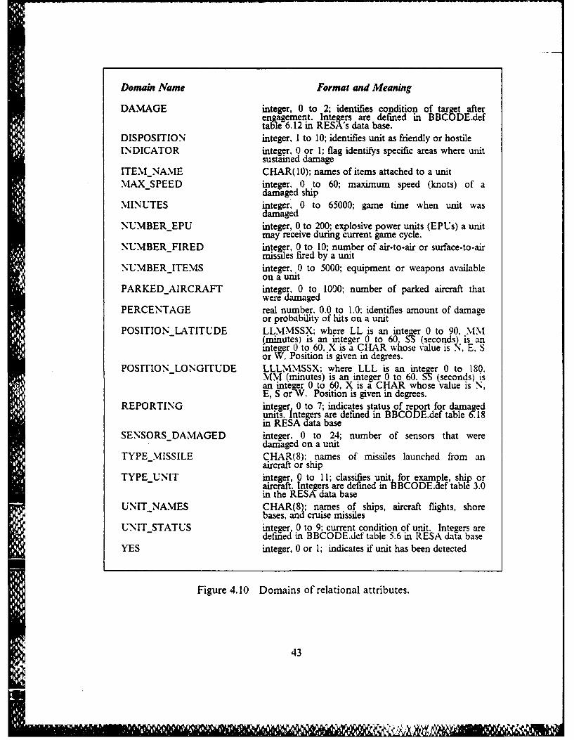
Domain Name Format and Meaning
DAMAGE integer, 0 to 2; identifies condition of target afterengagement. Integers are defined in BBCODE.deftable 6.12 in RESA's data base.
DISPOSITION integer, I to 10; identifies unit as friendly or hostileINDICATOR integer. 0 or 1; flag identifys specific areas where unit
sustained damageITEMNAME CHAR(10); names of items attached to a unitMAX SPEED integer. 0 to 60; maximum speed (knots) of a
daraged shipMINUTES integer, 0 to 65000; game time when unit was
damagedNUMBER EPU integer, 0 to 200; explosive power units (EPUs) a unit
may receive during current game cycle.NUMBERFIRED integer, 0 to 10; number of air-to-air or surface-to-air
missiles fired by a unitNUMBER ITEMS integer, .0 to 5000; equipment or weapons available
on a unitPARKED AIRCRAFT integer, 0 to 1090; number of parked aircraft that
were damagedPERCENTAGE real number. 0.0 to 1.0; identifies amount of damage
or probability of hits on a unitPOSITION LATITUDE LLMMSSX; where LL is an integer 0 to 90, MM
(minutes) is an integer 0 to 60 SS (seconds) is aninteger 0 to 60, X is a CHAR whose value is N, E, Sor NV. Position is given in degrees.
POSITIONLONGITUDE LLLMMSSX: where LLL is an integer 0 to 180,MM (minutes) is an integer 0 to 60. SS (seconds) isan integer 0 to 60, X is a CHAR whose value is N,E, S or,V. Position is given in degrees.
REPORTING integer 0 to 7; indicates status of report for damagedunits. integers are defined in BBCODE.def table 618in RESA data base
SENSORS DAMAGED integer. 0 to 24; number of sensors that weredariaged on a unit
TYPE MISSILE CHAR(8); names of missiles launched from anaircraft or ship
TYPE UNIT integer, 0 to 11; classifies unit for example, ship orSaircrat. Integers are defined in bBCODE.aef table 3.in the RESA data base
UNIT-NAMES CHAR(8); names of ships, aircraft flights, shorebases, and cruise missiles
UNIT-STATUS integer 0 to 9; current condition of unit. Integers aredefifed in BBCODE.def table 5.6 in RESA data base
YES integer, 0 or 1; indicates if unit has been detected
Figure 4.10 Domains of relational attributes.
43
* ,' ,LO
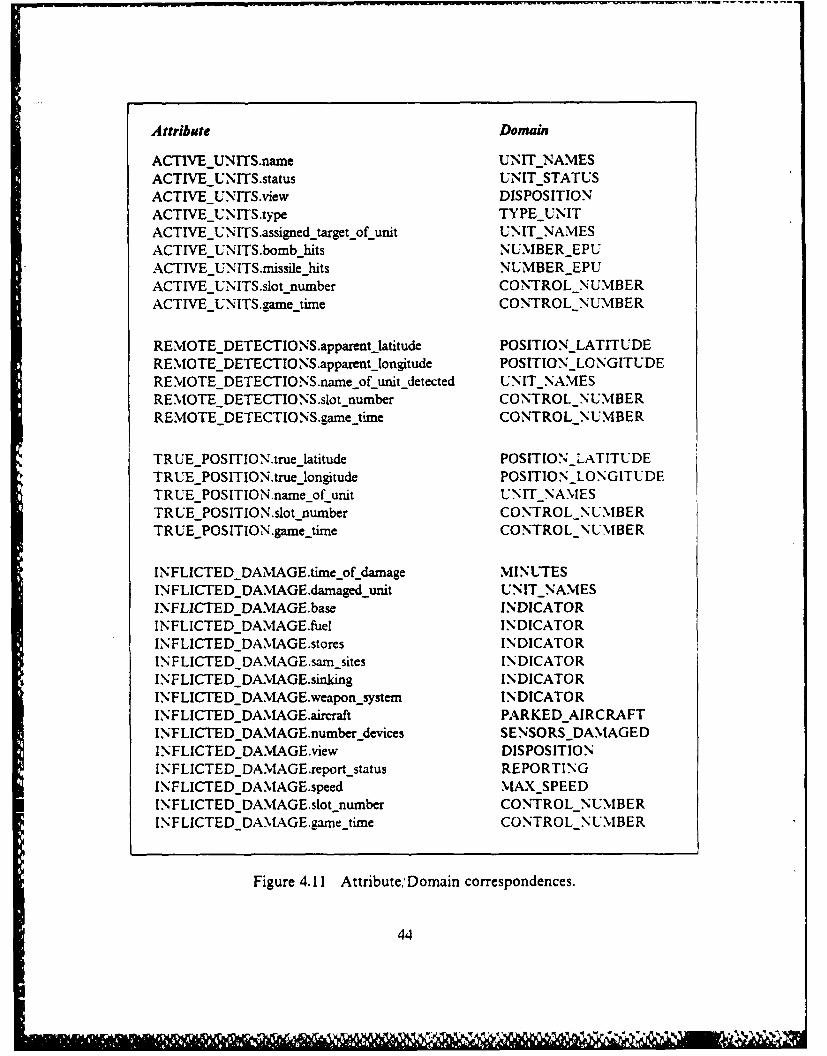
Attribute Domain
ACTIVE UNITS-name UNIT -NAMESACTIVE UNITS-status UNIT -STATUSACTIVE UNITS-view DISPOSITIONACTIVEUNITS-type TYPE -UNITACTIVE -UNITS .assigned.target..of .unit UN IT -NAMESACTIVE -UN.'ITS .bomb hidts NUMBER EPUACTIVE UNITS.n-issile -hits NUMBER EPUACTIVEUNITS.slot -number CONTROL NUMBERACTIVE UNITS .game timne CONTROL NUMBER
REMlvOTE-DETECTIO NS.apparent~latitude POSITION-LATITUDEREMIOTE-DETECTIONS.apparentjongtude POSITION-LONGITUDEREMOTEDETECTIONS.name-of unit-detected UNITNAMESREMOTE DETECTIONS.slot number CONTROL NUMBERREMOTE DETECTI NS.gametjime CONTROL N UMBER
TR UE POSITION-true -latitude POSITION LATITUDETRUE -POSITION.true 1ongitude POSITION LONGITUDETRUE POSITION-name-of unit U'NIT NAMESTRUE -POSITION.slot -number CO NTROL-N LMBE RTRUEPOSITION.gamejimne CONTROL NUMBER
INFLICTED-DAM'vAGEtime-of damage MINUTESINFLICTED DAMAGE.damaged unit UNIT NAMESI.NFLICTED DAMIAGE.base INDICATORINFLICTED DAMAGE.fuel INDICATORINFLICTED DAM vAGE.stores INDICATORINFLICTED DAMAGE-sam sites INDICATORINFLICTED DAMAGE.sinking INDICATORINFLICTED DAMAGEweapon ~system INDICATORINFLICTED DA.MAGE.aircraft PARKED-AIRCRAFTINFLICTED DAMAGE.number devices SENSORS-DAMAGEDINFLICTED DA.MAGE.view DISPOSITIONINFLICTED DAM'vAGE.report status REPORTINGINFLICTE DDAMAGE.speed MAX5 PEEDINFLICTED DA.MvAGEslot number CONTROL -NUMBERINFLICTED DAMAGE.gaxnejime CO NTROLNUMBER
Figure 4.11 Attribute,;Domain correspondences,
44

Attribute Domain
DYNAMICS INFORNMATION-name UNIT NAMESDYNAMICSJINFO RMATIO N-store-damagze PERCENTAGEDYNAMNICSI.NFORM'vATION.huildamage PERCENTAGEDYNA.MICSJN'.FORMATION.samjamage PERCENTAGEDYNAMICSJ NFO RMNATIO N.topside-damage PERCENTAGEDYNA.MICSINFO RMATION.fuelfiamage PERCENTAGEDYNAMNICS INFORM'vATION.identilication ITEM_NAM'vEDYNAMICS N".FORMATION-remaining NUMBERITEMISDYN'AMICS INFORMATION.slot-number CONTROL NUMBERDYNAMICSJINFORMATION-game-timne CONTROL NUMBER
ENGAGEM*vENTLDATA.name-of engagjinit UNIT NA.MESENGAGEMENT DATA.tvpe of missile fired TYPE MISSILEENGAGEMENT DATA.nurnber-of missiles-fired NU.MVBERFIREDENGAGEMIEN.\DATA.probability-hit PERCENTAGEENGAGEMENT DATA.status UNIT-STATUSENGAGEMENT DATA.view DISPOSITIONENGAGEMENT DATA.detected YESEN GAGEM% ENT DATA.tar~et status DAMAAGEDENGAGEMENT..DATA .target_type TYPE-UNITENGAGEMvENT DATA .probability hit target PERCENTAGEE NGAGEMIENT DATA.unit-latitude POSITIONLATITUDEENGAGE'VIENT-DATA.nt_longitude POSITIONLONGITUDEENGAGEM'vENT DATA.target_latitude POSITIO N-LATITUDEENGAGEMvEN.\TDATA.targetjlongtude POSITION-LONGITUDEENGAGEM'vENT DATAslot-number CONTROLNUMBEE'NGAGEMvENT DATA.game time CONTROLNUMBER
Figure 4.11 Attribute; Domain correspondences. (cont'd.)
There are no interrelation constraints listed for this relational data base design.
Interrelation constraints usually occur when entity classes are subclasses of other entity
classes and when domains themselves are entity class In this case, the domains listed
for each member attribute were defined as character STRINGS and not other entity
classes.
45

5. Sample Data Base Queries
This section serves two functions. First, it ties the SDM and the RelationalData Base Design together. Several queries are made on the previously defined
relations in order to demonstrate what the analyst or player will be able to extract fromthe data base. In addition, it explains how ORACLE's data manipulation language,
SQL is used to retrieve data.
a. Basic ORACLE SQL Commands
The basic SQL commands are SELECT, CREATE, and INSERT. SELECT
retrieves rows of data from a table, CREATE defines a new table, and INSERT entersrows of data into a table. The SELECT command is used for data base retrieval. It isthe most common operation done with ORACLE. The basic SELECT command has
two parts, called clauses;
1. The SELECT clause - lists the columns from the table to be retrieved.
2. The FROM clause - names the tables where the columns are located.The SELECT clause is always entered first and immediately followed by the FROMclause. These two commands would display all rows of information from the table. Inorder to select only specific rows of data, a WHERE clause must be added to the basicstatements of SELECT and FROM, as demonstrated in Appendix B and in the next
section. The WHERE command causes ORACLE to search the data in the table and
retrieve only those rows that meet a search-condition. These conditions are varied byusing AND, OR, BETWEEN and other clauses provided by ORACLE as clarifying
statements. If more than one table of data needs to be queried for the information.then ORACLE will use a JOIN command to obtain the data. [Ref. 221
b. User Types of Queries
These queries support two kinds of' information retrieval. Figures -1.12 and4.13 describe questions of possible interest to an active player of the RESA wargame
who would be using the workstation as DSS. The second type of information ischaracteristic of a question an analyst using the system might ask (Figure 4.14). Itshould be noted that each of the three figures uses a different SQL format for
retrieving the data. They are a normal SELECT query, a subquery using two different
relations, and a JOIN query, which pulls the information for the final answer frommore than one table. This is different from a subquery. A subquery may conduct
operations on multiple tables, but it obtains the final answer only from one table.
46

Question: What is the last known position and time for the Soviet submarine
Gulfl?
SELECT (unit detected, apparent_latitude, apparentlongitude, game-time)
FROM (remote detection historical)
WHERE unit-detected - gulfl
AND game-time > 38
Result:
unit apparent apparent gamedetected latitude longitude time
Gulfl 32 23N 24 36E 44Gulfl 33 23N 23 36E 45
Note: Current game time is 54. The user had to access the historical
data table to be sure of obtaining an answer since current tables
only contain data from the last few game cycles.
Figure 4.12 Player SQL sample 1.
47

Question: How much air activity has been detected over Petro?
SELECT (count (distinct unit-detected)}
FROM (remote detections)
WHERE (apparent_latitude, apparent_longitude) -
GROUP BY gametime
SELECT (true_latitude, true_longitude)
FROM (active unit)WHERE name = Petro
AND game time > 45
AND true-latitude BETWEEN (truelatitude + 2
and true-latitude - 2)
AND true-longitude BETWEEN (truelongitude + 2
and true-longitude - 2)
Result:
game time unit-detected
46 23
47 26
48 29
49 30
Note: Current game time now equal to 49.
Figure 4.13 Player SQL query number 2, (subquery).
48
I r) 6,, ,,' .¢,,, ,;, . .'+t+,;,-.7 A.; . , ,,,.k<z+p .<.,-. -,. -+;;..,, . +?...+ ;

Question: What is the average consumption of SAMs for the VINSON class
of ships during the first 10 minutes of combat (once incoming cruise
missiles have been detected) and the total number of successful
intercepts of these missiles.
SELECT {active unit. type, count (activeunit. type)
avg (dyn info.remaining), sum (engagedata.target_status)}
FROM dynamic-information, engagement-data, activeunits}
WHERE active-unit. type = 3
AND activeunit.slotnumber = dynamic information.slot-number
AND dynamic information.identification - SAM
AND engagement data.game time BETWEEN (engagement data.game_time
> = 32 and engagement data.game_time < = 41)
AND engagement data.target type = 5
AND engagement data.targetstatus = 1
AND engagement data.unitname = active units.name
Result:
active units count avg(dyn info sum(engagedatatype (active-units) remaining) target status)
3 4 7 11
Note: It is assumed one knows the initial quantity of SAMs.
Figure 4.14 Analyst SQL query sample, (JOIN).
C. SUMMARYChapter IV described methodology used to develop the Relational Data Base
Design for the C2 workstation. This involved mapping the SDM to the relational
DBMS, ORACLE. which NPS chose for their C2 workstation. The basic components
of this design are relations, domains and attribute,:domain correspondences, andinterrelation constraints. The second major section of this chapter identified the current
49

system used by NOSC and how NPS's system would have to be constructed in a very
similiar fashion. Two additional programs need to be developed. The first program is
required to organize the data into six tables after it is extracted from the RESAwargame. The second program is needed to format the data in order to transmit it from
the RESA wargame to the workstation via the ETHERNET. It was suggested that twosets of relational tables be implemented in the data base to permit the user to accessthe data during game execution. The first set would contain historical files for postgame analysis, while the second set of tables would contain only those records from the
most current game cycle. These tables were described in detail and used to construct
several sample SQL queries to illustrate the types of information which can be
extracted from the data base.
50
im

V. SUMMARY
A. REVIEW OF THE PROBLEMThis thesis supported the Naval Postgraduate School's (NPS) research into the
development of a multimedia (text, voice, graphics), command and control (C2)
workstation as a Decision Support System (DSS) to aid players of the Research,
Evaluatl-n, and System Analysis (RESA) facility. The problem involved interfacing the
the C2 workstation to RESA to support post game analysis of the data and to permit
players of the wargame to access real time data during game execution. This coincided
with the Navy's overall problem of obtaining a workstation flexible enough to work
with a wide variety of C2 systems and adaptable enough to meet the requirements of a
diverse set of users. This meant using both voice and keyboard natural language
interfaces on the workstation.With this understanding, the NPS chose the Sun microsystems' version of UNIX
and ORACLE. a relational data base management system (DBMS) to function as the
C2 workstation. The primary reason is that it supported a wide variety of multimedia
functions including voice capability in the near future. NPS's long term goal is to use
this workstation to provide players and analysts the capability of real time data
extraction by using a voice, natural language interface to operate the system. As such,
it was the goal of this thesis to define the boundaries of the problem and propose a
data base design for the Sun workstation using data supplied by the Naval Ocean
Systems Center (NOSC).
B. CONCLUSIONS
If it is assumed the RESA data is a good representation of data arriving from
operational systems, then it is possible to make several conclusions in using the Sunworkstation as a DSS.
1. It is possible to define a data element dictionary for a military environmentusing the design of industry standard DBMS systefns.
2. A duplicate set of relational tables can be defined to store historical data andcurrent data to allow a microsystem to operate as a DSS.
3. The design of the DSS may allow real time retrieval of aggregated data. inrespon se to user SQL or natural language queries, if the hard \are and softwareoperating speed is suffcient.
4 4. It is possible to use a dedicated processor for off-line retrieval of data from anoperational system.
51

5. A series of logical steps can be defined to develop a natural language interfaceto benefit infrequent users of the DSS.
C. RECOMMENDATIONSAfter analyzing the data and conferring with people at NOSC, we recommend
that the relational data base design be structured in accordance with the way data are
extracted from the RESA wargame. It is already organized into logical tables and this
will minimize the initial amount of work required to implement the system. Those
changes in the design that did occur were in support of NPS's decision to use the C2workstation in the additional role as a DSS. Therefore, we recommend that two sets of
relational tables be maintained in the DBMS on the workstation. The first set wouldcontain all data extracted from the wargame scenario, while the second set would be an
abbreviated file containing those records extracted from the last few game cycles.
D. RECOMMENDATIONS FOR FURTHER STUDY
The relational data base design is just the first step in the total research programin progress at NPS. Five additional programs were identified that need to be developed
before this project can be completed. These include:
1. DISK PIPE.EXEC program - is required to replace .OSC'sTAPE-PIPE.EXEC program. This is needed to clean up the data after it isextracted from the wargame and to organize the data into the six logical tables.
2. An ETHERNET program module - this second program module is required tof'ormat the data in order to transmit it over the ETHERNET to the Sunworkstation.
3. ORACLE interface module - once the Sun workstation receives the data it mustbe reformated again in terms of ORACLE so it can be written to theappropriate files.
4. Menu driven module - the author recommends a menu driven interface bedeveloped to assist the user in retrieving information from the data base.A* thougih ORACLE uses SQL for this prbcess the user must still be familiarwith the data base organization for this method to be effective.
5. Natural language module - the ultimate goal of the svstem is to access the datavia a natural languaee. It is due to the difficulty that will be encountered indeveloping this ffiodlile that the menu driven ihtertace was proposed as aninterim solution to access the data base.
The first three programs should be considered as components of the larger project tointerface the Sun workstation to the RESA facility. Once this stage is complete then
the relational data base design can be implemented on the workstation using ORACLE
as the DBMS. The next stage. developing a menu driven query program (as an interim
solution until a natural language can be developed) is considerably larger in scope then*the first three. As stated previously, menu driven interflaces require less memory and
52
"1 ," . .. dn1 . ) t. , d J ,a ". " €' d . * ''a.d",' ' d' / '."""a',

appear well suited to command and control queries. The natural language program is
_ the largest and most difficult task to be accomplished in the future. However, it offers
the potential to reduce the learning curve for players using the system. It will aid the
infrequent user in accessing data and in making queries that would be difficult to definein SQL. The payoff from this type of C2 system, with these capabilities, is a more
robust approach to distributed command and control [Ref. 4: p. 11.
E. POTENTIAL PROBLEM AREAS
There are several potential problems that may hinder the implementation of' the
proposed relational data base design and affect its efficiency when the workstation
becomes operational. The biggest concern lies with the processing capability of the Sun
workstation. Is it fast enough to handle the volume of data being transmitted from the
RESA wargame within the designated one minute cycles? It is understood that the
ETHERNET will ultimately control the maximum rate at which data is transmitted to
the workstation, but will it be so busy accepting and receiving data that it will be too
slow in performing any other flunction? The total quantity of data retrieved from one
game lasting 75 minutes. can require anywhere from 55 to 100 Megabytes of disk
storage. Even breaking down the data into one minute sections averaging just one
Megabyte of information would still require a great deal of processing time. Multiply
this number by the series of steps listed above and it becomes easy to understand how
the system may not be unable to support and process such a large amount of data in a
timely manner.
A second issue, related to the first, is how "real time" the DSS will be in accessing
the data. There may be so much data that it will be infeasible to update the current
relational files every game minute. It may be necessary to extend this time to two or
three minute cycles. How effective would calculations be if they were made from data
obtained only every 2 or 3 minutes, especially when RESA can lengthen the game cycle
time at random. How then, would this affect the players using the workstation as a
DSS?
SA final issue concerns the size of the overall data base collected for eachwargame. Although the relational data base is a two dimensional flat file it is
convenient to think of it as a three dimensional file with the third dimension being
time. At game time = I the data base consists of single values for every data element
in the program. At game time = 2 the data base grows to two values flor every data
53
element. With the data base growing with each time cycle it is easy to see that this
process will generate a very large and possibly unmanageable data set in a very short
time. There are several possible approaches to this problem which take advantage of
the fact that not all data changes each time and that not all data must be saved. This
leads into the idea of adding temporal semantics into the DBMS. Significant savings in
data base size and processing speed could be achieved just by processing data which
has changed since the last game time. We feel this area is worth further study since it
offers a potential solution for all three identified problems.
These problems are going to be compounded as NPS expands the network by
adding workstations. Not only will Sun stations be used but also existing HP 9020s. As
such, the interface to establish correct protocol procedures between these two systems
must also be addressed and developed.
The final problem area which will affect the continued performance of the Sun
workstation is NPS's ultimate goal to eventually tie this system into the Defense Data
Network (DDN). This will allow direct interface with the RESA wargame located at
NOSC. If this can be accomplished then these systems should be able to operate in a
similiar environment from ship-to-ship or shore.
In summary, there are a large number of questions that still need to be answered.
This paper defined the project in concrete terms and proposed a relational data base
design for the workstation based on work completed at NOSC. Problems were raised
which need to be resolved before further work can continue while others will resolve
themselves as the system becomes operational. Feedback provided by the players in the
game will greatly enhance the effectiveness of the system as a DSS. If the system really
is evolutionary, as all DSSs are supposed to be, then it will be able to meet the
proposed changes in design and accommodate new systems such as the HP 9020 and
the system at NOSC.
54
M -, ....

.4
APPENDIX ASUN WORKSTATION
This section describes the system selected by the Naval Postgraduate School to
be used as the Command and Control Decision Support System to support RESA.
There are two basic components; the Sun Workstation using Sun's version of UNIX
operating system, and ORACLE, the Relational Data Base Management System
(RDBMS).
1. SYSTEM HARDWARE
The Sun-3 product family is a group of 32-bit systems based on the Motorola
MC 68020 CPU chip and the high-speed 32-bit VMEbus. It comes with a standard 2
Megabytes of real memory expandable up to 16 Megabytes and can address up to 256
Megabytes of virtual address space. The system includes a floating point accelerator,graphics processor board, and graphics butler. The floating point accelerator runs upto four times faster than the MC68881 and gives two times the performance of' aVAX780 using a floating point accelerator. The accelerator complies with the IEEE754 version 10 standard and supports both 32-bit and 64-bit floating-point operations.
The graphics board can render 40,000 2D vectors per second or 25,000 3D vectors per
second. The graphic buffer augments the graphics board and is intended for
applications where 3D transformations and hidden surface remove is time critical. This
combination can shade and remove hidden surfaces of 3D polygons faster than one
million pixels per second or up to 35 million pixels per second for arbitrary polygons.
Peripherals that can be attached to the system include SMD disks ranging in size from
84 Megabytes to the 474 Megabyte 'Eagle' disk, a nine-track disk a one quarter inch
cartridge tape, and SCSI disks and tapes. All systems communicate via the
ETHERNET which is a 10 Megabit-per-second coaxial cable local area networkfacility. [Ref. 21: pp. 7-10]
2. SYSTEM SOFTWARE
The Sun Workstation runs an enhanced version of the 4.2BSD UNIX system
derived from the University of California at Berkeley. The system provides support tbrinterprocess communication and local area networking. The UNIX system is equippedwith a host of software as a base level package. Supported languages are Pascal, C,
55
!'''

FORTRAN 77, and Assembler. There are utilities for performing statistical textprocessing and document preparation. In addition to the utilities package Sun hasadded User Interface package based on overlapping windows, and a graphics packageto support the more common graphics standards. [Ref. 21: p 3]
a. UNIXThe operating system uses a hierarchical file system to group related tiles
within a director'. A directory is simply a special case of file. Sun Microsystems havetaken this idea one step further into a Network File System. This is a facility forsharing files in a heterogeneous environment of machines, operating systems and
networks. Sharing is accomplished through a remote file system rather then reading orwriting files in place. This avoids the problem of each node maintaining their own file
system and thereby duplicating resources.
There are two main shells on the Sun operating system. They are the C Shellin the command interpreter part of the 4.2 BSD operating system and the Bourne Shell
which is the UNIX version 7 command interpreter. The two major external differencesbetween the two shells is that the C Shell provides job control and history. Job controlallows jobs to be run in the background or foreground. The history facility is used for
reissuing previous commands. The number of commands possible is specified by theuser. Major features that both shells provide to the user interface are
1. Analysis of the command line. Run the indicated command, passing theremainder of the command line as arguments to the command. Each coninandis run as a separate process.
2. The shells can redirect the standard input, output, and error files as defined bythe user.
3. Can connect multiple processes together via a "pipeline." The standard outputof one process is connected to the standard input or the next process in line.
4. File name expansion. Metacharacters are provided to indicate aggregates offiles. Matches can be made on single characters or strings of' chzrfacters in afilename.
5. Both shells provide user-defined search paths for finding conunands.Both shells can be used as a programming language. The syntax of the C shellcommands resembles the C programming language whereas the Bourne Shell resembles
Algol-68. [Ref. 21: pp. 35-37]b. Window Utility
Sun View is the Sun Visual, Integrated Environment for Workstations. It hastwo components; a User Interface and a Sun Guide. The Sun Guide is a programming
interface accessible via a collection of subroutine libraries. The user interface provides
56

multiple overlapping windows on the screen and each window runs independently of
the other. It is a collection of software utilities that exploit the graphical capabilities of
the Sun hardware. It uses a mouse as a pointing device as the primary mechanism for
interacting with the tools. This avoids having to type in a response and having to wait
for a response. Windows can be moved around the screen as needed and when closed
becomes an "icon'; a small graphical object whose appearance sometimes suggests its
function. Some of the features provided by the Sun Window System are a shelltool,
iconedit, and mailtool. The shelltool provides a window-based interface to the
standard UNIX system command interpreters. Iconedit is used for designing icons and
cursors. Mailtool interfaces to the standard mail reading facility. [Ref. 21: pp. 21.-311
c. Mail Utility
The Sun station supports two types of mail routines; electronic mail and
electronic message. Electronic mail is similiar to sending a telegram. It can be read.
saved or edited. Electronic mail can be sent to the same machine, over a local network
or remote network. An electronic message is like calling someone up on the phone.
The person who receives the message can reply to it while the user waits. There are
four types of electronic messages; same machine, local network, broadcast, and system.
which are messages the system sends to the user's console. [Ref. 23: pp. 3-4]
57

APPENDIX BORACLE, A RELATIONAL DATA BASE MANAGEMENT SYSTEM
ORACLE is relational database management system plus a complete set of
integrated software tools for application development and decision support. These tools
include an
I. Application generator - this helps the user define an application by leadingthem through a simple question and answer dialogue.
2. Report generator - allows the creation of both production and ad-hoc reports.It will automatically .tormat any SQL query into a report with columns andheadings taken froni the data dictionary.
3. Color graphics - permits display of data in color, in the form of pie or barcharts, and multi-line plots.
4. Document preparation - lets the user interleave the results of multiple data basequeries with text and graphics into a single lormatted report or document.
.5. Integrated data dictionary - contains all the information about tablesapplications, reports, and graphs and is automatically updated by the system asnew tables and applications are added to the data base.
Data is displayed in a two-dimensional table and is accessed via a standard user
interface. SQL (pronounced see-quel). SQL is an English-like language that can be
used directly from the terminal or embedded in standard programming languages. SQL
includes commands for
1. Query - retrieving data from the data base.
2. Data manipulation - inserting, updating, and deleting data.
3. Data definition - adding new tables.
4. Data control - preventing access to private data.
SQL specifies operations in terms of what is to be done and not how to do it. It is a
nonprocedural language.
The basic SQL commands are SELECT, CREATE, and INSERT. SELECT
retrieves rows of data from a table, CREATE defines a new table, and INSERT enters
rows of data into a table. The SELECT command is used for data base retrieval. It isthe most common operation done with ORACLE. The basic SELECT command has
two parts, called clauses;
I. The SELECT clause - lists the columns from the table to be retrieved.
2. The FROM clause - names the tables where the columns are located.
58
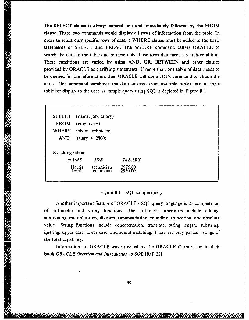
The SELECT clause is always entered first and immediately followed by the FROM
clause. These two commands would display all rows of information from the table. In
order to select only specific rows of data, a WHERE clause must be added to the basic
statements of SELECT and FROM. The WHERE command causes ORACLE to
search the data in the table and retrieve only those rows that meet a search-condition.
These conditions are varied by using AND, OR, BETWEEN and other clauses
provided by ORACLE as clarifying statements. If more than one table of data needs to
be queried for the information, then ORACLE will use a JOIN command to obtain the
data. This command combines the data selected from multiple tables into a single
table for display to the user. A sample query using SQL is depicted in Figure B.1.
SELECT (name, job, salary)
FROM (employees)WHERE job = technician
AND salary > 2800:
Resulting table:
NAME JOB SALARY
Harris technician 2975.00Terrill technician 2850.00
Figure B.1 SQL sample query.
Another important feature of ORACLE's SQL query language is its complete setof arithmetic and string functions. The arithmetic operators include adding,
subtracting, multiplication, division, exponentiation, rounding, truncation, and absolute
value. String functions include concatenation, translate, string length, substring,
instring, upper case, lower case, and sound matching. These are only partial listings of
the total capability.Information on ORACLE was provided by the ORACLE Corporation in their
book ORACLE Overview and Introduction to SQL [Ref. 221.
59

APPENDIX CRESA BLACKBOARD DATA
The Naval Ocean Systems Center (NOSC) provided the data used in the database design. After it is run through the TAPE PIPE.EXEC program it is separated
into six separate files corresponding to RESA tables. This section lists a portion of'each of those files (for one game time slot only) and their associated fields. It also
Data Item Field Name
NFI02 NamePHENX Missile TVeBK133 Assiened IrareetI Nunibered Fiired65 Probability of Hit
StatusView
l In UseDetectedStatus of Target
I Type of'Tareet65 Pfobabilitv Hit Target+ 0.7959 Latitude 6f Unit+ 2.8293 Longitude of Unit+ 0.8048 Latitude of Target
2 ,.83'9 Longitude of Target101817 Pointer12 Length of Entry in Blackboard101817 Base of Table0 Pointer IndexI Slot Number21 Game Time
Figure C.1 Engagement data.
explains the relationship between each of the tables. The last six data items are notpart of the data collected from the wargame. They are used for control purposes in the
program and the names of these fields are identical in the rest of the tables, so they willnot be repeated again. The two important control numbers are the slot number andthe game time. The slot number uniquely identifies each record collected under the
same game time. The game time distinguishes between like records within the same file.
Information is collected from the RESA wargame once. sometimes more. during eachgame time or cycle (one nunute of game play) for all the files. The values of data items
within each record may have changed or records may have been added or deleted.
60

rr.wwr wrwrwwnorvv
Data Item Field Name
+ 0.0100 Store Damage+ 0.0100 Hull Damage+ 0.0000 Sam Damage+ 0.0000 Top Side Damage+ 0.0100 Fuel Damage21 Equriment "Identification) .unmber Remaining
Figure C.2 Data on ship dynamics.
Data Item Field Name
Petro Name2 Status3 View7 Type0 Attack Index0 Hits0 Missile Hits
Figure C.3 Platform unit data.
Data Item Field Name
+ 0.9279 True Latitude+ 2.7655 True Longitude
Figure C.4 Position data.
All the files are related through the slot number and the game time. The position
file and platform file match up one-to-one by slot number and game time. This reveals
the true position of each unit. The remote detection file and platform unit file match
up one-to-one for game time but the detectee number in the remote detection file is
matched to the slot number in the unit plattbrm unit file. This identifies the target that
61

Data Item Field Name+ 0.8195 Apparent Latitude+ 2.7799 Apparent Longitude20 Detectee
Figure C.5 Remote detection data.
Data Item Field Name
69 Time6 Unit0 Base0 Fuel0 Stores0 Samsites1 Sinking0 Weapon Systems1) Next Indek0 Aircraft0 Number Devices2 View.4 Report StatusI ModifiedI Name Index0 Speed
Figure C.6 Unit damage data.
is detected. In the unit damage file, the data item "unit" matches to the slot number in
the platform unit data file under the same game time. This identifies the unit which
received damage. The last relationship is between the data on ship dynamics and
platform unit data. These files match one-to-one for slot number and game time to
identify the appropriate dynamic information for the right unit.
62
APPENDIX DSEMANTIC DATA MODEL FOR THE DSS C2 WORKSTATION
D YNAMICSINFORMA TIONdescription: contains dynamic data for ships, submarines, shore bases,and afrcraft tlights.
member attributes:
Namevalue class: UNITNAMES
Store-damagevalue class: PERCENTAGE
Hulldamagevalue class: PERCENTAGE
Samdamagevalue class: PERCENTAGE
Topside..damagevalue class: PERCENTAGE
Fueldamagevalue class: PERCENTAGE
Identification
description: identifies equipment item attached to unit,for example, radar or rfmissile type.
value class: ITEM NAMEmultivalued
Remaining
description: number of equipment items remaining underIdentification due to operational damages or expenditures.value class: NUMBER ITEMSmultivalued
identifiers:Name
Figure D. I SDM for the C2 workstation.
63

ACTIVE UNITSdescription: Contains names, pointers, and other "quick reference" datafor al active ships, shore bases, aircraft flights, and cruise missiles.
member attributes:
Namevalue class: UNIT NAMESmandatory
Status
description: contains present condition of unit, for example,sinking or on station.value class: UNIT STATUSmandatory
View
description: identifies character of unit, for example, hostile.value class: DISPOSITIONmandatory
Type
description: identifies kind of unit, for example, submarineor cruise missile.
value class: TYPEUNITmandatory
Assined targetof unit
description: it indicates the target unit is attacking.
value class: UNIT NAMES
Bomb-hits
description: contains number of bomb hits a unit receivedduring a current game cycle.value class: NUMBEREPUmultivalued
Alissile hits
description: contains number of missile hits a unit receivedduring a current game cycle.value class: NUMBER EPUmultivalued
identifiers:Name
Figure D. I SDM for the C2 workstation. (cont'd.)
64

REMO TEDE TECTIONS
description: contains detected tracks of active units.
member attributes:
Apparent-latitudevalue class: POSITIONLATITUDEmandatory
comment: must be in degrees.
Apparentlongitude
value class: POSITION LONGITUDEmandatory
comment: must be in degrees.
Name of unit detected
value class: UNITNAMES
identifiers:
Name of unit-detected
TR UEPOSI TION
description: identifies ground true latitude and longitude of activeunits.
member attributes:
True-latitude
value class: POSITIONLATITUDE
comment: must be in degrees.
True lon gitudevalue class: POSITIONLONGITUDE
comment: must be in degrees.
Name of unitvalue class: UNIT NAMESmandatory
identifiers:
Name
Figure D.1 SDM for the C2 workstation. (cont'd.)
65
INFLICTED-DAMAGE
description: contains damage information relative to ships, aircraftand various shore installations.
member attributes:
Time..of damagevalue class: MINUTES
Damaged unitvalue class: UNIT NAMESmultivalued
Base
description: indicates whether base did or did not receive damage.value class: INDICATOR
Fuel
description: indicates whether hull or fuel stores did or did notreceive damage.value class: INDICATOR
Storesdescription: indicates whether weapon stores did or did notreceive damage.value class: INDICATOR
Sam-sites
description: indicates whether SAM sites did or did not receivedamage.value class: INDICATOR
Sinking
description: indicates whether a ship is or is not sinking.value class: INDICATOR
Weaponsystem
description: indicates whether weapon system did or did notreceive damage.
value class: INDICATOR
Aircraft
description: contains number of damaged parked aircraft.value class: PARKED AIRCRAFT
Figure D.1 SDM for the C2 workstation. (cont'd.)
66

Number-devices
description: contains number of sensor devices that weredamaged.
value class: SENSORSDAMAGE
View
description: identifies owner of damaged unit, example, hostile.
value class: DISPOSITION
Report-Status
description: for example, report needed or report sent.
value class: REPORTING
Speed
description: maximum speed of ship after damage.
value class: MAX SPEED
identifiers:
Dama2e_unit
ENGAGEiENTDA,4TA
description:. contains force engagement data for ships, aircraft, andcruise missiles which are atta~king opposing units.
member attributes:
Name oeng agingunit
value class: UNITNAMESmandatorvmultivalu6d
Type of missile fired
description: for example, sparrow, phenx.
value class: TYPE-MISSILEmultivalued
Assignedjtarget_ of missile
value class: TYPEUNIT
Number of missiles_fired
value class: NUMBER FIREDmultivalued
Figure D.I SDM for the C2 workstation. (cont'd.)
M67

Probabilityhit
description: contains probability of hitting target consideringthe range where missile was fired.
value class: PERCENTAGE
Status
description: contains present condition of unit, for example,proceeding or on guide.value class: UNIT STATUSmandatory
View
descriotion: identifies character of attacking unit, example,friendly.value class: DISPOSITIONmandatory
Detected
description: indicates unit has been detected.
value class: YES
Target-status
description: indicates whether target was missed, hit andengagement is over, or engagingt1he target.
value class: DAMAGEDmultivalued
Target_type
description: identifies kind of unit being attacked, for example,ship.
value class: TYPEUNITmandatory
Probabilityjhit..target
description: contains probability that missile will hit targetgiven the target's electronic counter measure capabilities.value class: PERCENTAGE
Unit-latitudevalue class: POSITION LATITUDE
comment: must be in degrees.
Figure D.1 SDM for the C2 workstation. (cont'd.)
68
rg

Unit Jongitude
value class: POSITIONLONGITUDE
comment: must be in degrees.
Target-latitude
value class: POSITIONLATITUDE
comment: must be in degrees.
Target Jongitude
value class: POSITION LONGITUDE
comment: must be in degrees.
identifiers:
Nameof engagingunit
UNI TNA MES
description: contains names of all ships, subs. aircraft, cruisemissiles and shore stations.
interclass connection: subclass of STRINGS where length is less thaneight characters.
UNI TS TA TUS
description: contains present condition of each active unit, forexample, being deleted, proceeding or recovery.interclass connection: subclass of STRINGS where format isnon-negative integer less than 10.
TYPEUNIT
description: identifies kind of unit. for example, surface or shorebase.
interclass connection: subclass of STRINGS where format is apositive integer less than 11.
DISPOSITION
description: identifies whether unit is neutral, friendly, hostile,or unknown.
interclass connection: subclass of STRINGS where format is apositive integer less than 11.
Figure D.! SDM for the C2 workstation. (cont d.)
69

NUMBEREPUdescription: identifies number of explosive power units (EPU)received by a unit.
interclass connection: subclass of STRINGS where format isnon-negative less than 201.
MINUTES
description: identifies game time when unit was damaged.
interclass connection: subclass of STRINGS where format isnon-negative integer less 2401.
INDICA TORdescription: statement indicates whether unit did or did not receiveany damage.
interclass connection: subclass of STRINGS where format is 0 or I.
PARKEDAIRCRAFT
description: identifies number of parked aircraft that were damaged.interclass connection: subclass of STRINGS where format isnon-negative integer less than 1001.
SENSORSDA MA GED
description: indicates number of damaged sensor devices.
interclass connection: subclass of STRINGS where format isnon-negative integer less than 25.
REPOR TINGdescription: indicates reported status on damaged units, forexample, report received.
interclass connection: subclass of STRINGS where format isnon-negative integer less than eight.
MX SPEED
description: indicates maximum speed of ship, in knots, after beingdamaged.interclass connection: subclass of STRINGS where format isnon-negative integer less than 61.
PERCENT.4GE
interclass connection: subclass of STRINGS where format is a realnumber between or equal to 0 and 1.
Figure D.I SDM for the C2 workstation. (cont'd.
70

ITEMNAME
description: identifies name of equipment item attached to unit.
interclass connection: subclass of STRINGS where length isless than 10 characters.
NUMBERITEMS
description: contains amount of equipment items still operatingafter a unit is damaged.interclass connection: subclass of STRINGS where format isnon-negative integer less than 5000.
TYPEMISSILE
interclass connection: subclass of STRINGS where length is less thaneight characters.
NUMBER FIRED
description: contains number of missiles fired at a target from oneunit.interclass connection: subclass of STRINGS where format isnon-negative integer less than 10.
YES
description: indicates unit has been detected.
interclass connection: subclass of STRINGS where format is 0 or 1.
DAMA GEDdescription: indicates if target was missed by a missile,hit by a missile and engagement over, or engaging target.interclass connection: subclass of STRINGS where format isnon-negative integer less than 5.
POSITIONLA TITUDE
description: indicates latitude of unit in degrees.
interclass connection: subclass of STRINGS where format is numberLLMMSS and X is a character.
POSITIONL ONGITUDE
description: indicates longitude of unit in degrees.
interclass connection: subclass of STRINGS where format is numberLLLMMSS and X is a character.
Figure DI SDM for the C2 workstation. (cont'd.)
71

LIST OF REFERENCES
1. Svobodova, Liba "Performance Problems in Distributed Systems," Information,Volume 18, Number 1, February 1980, pp. 21-38.
2. Wand 1. C., Distributed Computing, Edited by Fred B. Chambers. David A. Duce,and Gillian P. Jones, London: Academic Pregs Inc., 1984.
3. Rose. C. W. and Schoeffler J. D., "Distributed Computer Intelligence for DataAcquisition and Control." IEE Transactions on Nuclear Science, Volume NS-23.Number 1, February 1976, pp. 38-52.
4. Naval Ocean Systems Center, NOSC RX 21.242, Subproject Program Plan, NoRX 21242, Information Management Assessment/Display, 15 August 1985.
5. Parker, Yacup, Multi-N1icroprocessor Systems, London: Academic Press Inc.,1983.
6. Zied A. Command Workstation in a Simulated Wargame Environment. A researchpro osaI at the Naval Postgraduate School to the -Naval Ocean Systems Center(NOSC), Joint Directory ofLabs C Technology Panel, 1984.
7. Naval Ocean Systems Center. Research, Evaluation, and Svstems Analysis (RESA)Training Handbook, San Diego: Sonalysts, Inc., August 1986.
8. Naval Ocean Systems Center, Report NOSC TR 1006, Menu-based NaturalLanguage Query'for Naval Command and Control, by G. A. Osga, December1984.
9. Conwell, Candace Lee, Unique Considerations in the Design of a Command andControl Decision System, M.S. Thesis, Naval Postgraduate School, Monterey,CA, June 1983.
10. Hafner. A. N., "Emergence of Decision Support Technology in MilitaryInformation Management Systems," Program Manager, Volume15, Number -4,July - August 1986,pp. 24-26.
11. Mittra Sitansu S., Decision Support Systems: Tools and Techniques, New York:John Wiley and Sons, 1986.
12. Tucker. Douglas K. and Van Dalsei, Danny E., .4 Decision Support System forBare-Base Planners, M.S. Thesis, Air Force Institute of Technology, Wright-Patterson Air Force Base, Ohio, November 1984.
13. Wagner, G. R.. "Decision Support Svstems: The Real Substance," lpteraces,Volume 11, Number 2, April 1991, pp. 7 7-86.
72

14. Kingstone Paul L., "Generic Decision Support Systems," Managerial Planning,Volume 9, Number , M arch-April 1981, pp. 7-11.
15. Bankes, Steven C., Future Military A lications For Knowledge Engineering, SantaMonica: Rand Corporation, July IN.
16. Orr, George E., Combat Operations CH!: Fundamentals and Interactions, AirpowerResearch Institute, Air University Press, Maxwell AFB, AL, July 1983.
17. Cardenas, Alfonso F., Data Base Management Systems, 2nd ed.. Boston: Allynand Bacon, Inc., 1985.
18. Rosenfeld. Pilar N., Investigation of. DBMS for use in a Research Environment.M.S. Thesis, California State University, Northridge, CA, July 1984.
19. Kroenke, David M., Data Base Processing, 2nd ed., Chicago: Science ResearchAssociates, Inc., 1983.
20. Hammer, M. and McLeod D., "Data Base Description with SDM: A SemanticData Base Model." A CM1 Transactions on Data Base Systems, Volume 6, Number3, September 198f, pp. 351-386.
21. Sun Microsystems. Sun Systems Overview, Sun Microsystems, 1986.
22. Ellison Lawrence. ORACLE Overview and Introduction to SQL, 2nd ed.,OR-C'LE Corporation, May 1985.
23. Sun Microsystems, Mail and Wessages Beginners Guide, Sun Microsystems, 1986.
73
WEMM

INITIAL DISTRIBUTION LIST
No. Copies1. Defense Technical Information Center 2
Cameron StationAlexandria, Virginia 22304-6145
2. Library Code 0142 2Naval Postaraduate SchoolMonterey, California 93943-5002
3. Dr. A Zied. Code 443Naval Ocean Systems Center271 Catalina BlvdSan Diego, California 92152-5000
4. LCDR R. F. Hudson. Code 20CNaval Air Development CenterWarminister, Pennsylvania 18974-5000
5. Mr. Elbert Wells. Code -3Naval Ocean Systems Center271 Catalina BvdSan Diego, California 92152-5000
6. Mr. J. Richardson, Code 411Naval Ocean Systems Center271 Catalina BlvdSan Diego. California 92152-5000
7. Office of the Joint Chiefs of StaffOJCSiJ8ATTN: LtCol D. McLain, USAFWashington, D.C. 20301
8. CDR J. Stewart. Code 55ST 2Naval Postgraduate SchoolMonterey, California 93943-5000
9. C3 Academic Group, Code 74 4Prot M. G. SovereignNaval Postgraduate SchoolMonterey, California 93943-5000
10. Prof D. Dolk, Code 54DKNaval Postgraduate SchioolMonterey, California 93943-5000
11. Capt Michael F. CarrollHQAFSPACECOM: LKYCPeterson Air Force BaseColorado Springs, Colorado 80914-5001
74