Embed Size (px)
Citation preview

19 Copyright © Canadian Research & Development Center of Sciences and Cultures
ISSN 1925-542X [Print] ISSN 1925-5438 [Online]
www.cscanada.netwww.cscanada.org
Advances in Petroleum Exploration and DevelopmentVol. 9, No. 2, 2015, pp. 19-24DOI:10.3968/6947
Analysis on Influential Factors of Well Temperature for Deepwater Drilling
SUN Shihui[a],*; YAN Tie[a]; BI Xueliang[a]; YU Guoqing[b]
[a] Petroleum Engineering College, Northeast Petroleum University, Daqing, China.[b] Daqing Oil Filed Co., Ltd. of PetroChina, Daqing, China.*Corresponding author.
Supported by National Natural Science Foundation of China (51374077).
Received 3 May 2015; accepted 13 June 2015Published online 30 June 2015
AbstractWellbore circulating temperature must be predicted accurately to prevent gas hydrate and safe well construction operations during deepwater drilling. A model for predicting wellbore temperature distribution in deep water wells during circulation has been developed in terms of thermodynamics theory in this paper. And the influential factorsare analyzed. Model calculation results indicate that temperature profile is strongly dependent on mud specific heat and thermal conductivity, mud density and flow rate dependence of temperature effects is small. Wellbore temperature is dynamic, temperature increases with the increase of circulating time, and tend to be constant when circulating time reaches a certain value. And geothermal gradients of formation under mud line have a significant influence on wellbore temperature.Key words: Temperature distribution; Deepwater drilling; Thermodynamics theory; Influential factors
Sun, S. H., Yan, T., Bi, X. L., & Yu, G. Q. (2015). Analysis on influential factors of well temperature for deepwater drilling. Advances in Petroleum Exploration and Development, 9(2), 19-24. Available from: URL: http://www.cscanada.net/index.php/aped/article/view/6947 DOI: http://dx.doi.org/10.3968/6947
INTRODUCTIONThe knowledge of down hole circulating temperature is essential to the design of drilling and cementing operations. During drilling operations high pressures
and low fluid temperature can cause formation of gas hydrates[1]. The formation of hydrates can result in several adverse effects such as plug formation in blowout preventers and subsea wellhead[2,3]. Inadequate knowledge of the temperature regime in the wellbore during cementing operation is one cause of cement job failures[4]. The precise knowledge of heat transfer is critical in the effort to prevent gas hydrate and safe well construction operations. The main purpose of this study is to developa model for predicting the temperature distribution in a circulating well and analysis the influence factors for deepwater drilling.
1. TEMEPERATURE MODEL Physical model for wellbore fluid flow and heat transfer in formation for deep water is shown in Figure 1. To obtain expressions for the temperature of fluid in the annulus and the drilling pipe, we set up an energy balance over a differential element of length, dz, of the annular fluid as shown in Figure 2.
rpi
rpo
rb
d
Sea water
Sea level
Annulus
zr
Drillstring
Marine riser
Insulating layer
Mud line
Casing
Cement sheath
Formation
z
Figure 1Physical Model for Wellbore Fluid Flow and Heat Transfer in Deep Water
20Copyright © Canadian Research & Development Center of Sciences and Cultures
Analysis on Influential Factors of Well Temperature for Deepwater Drilling
Q A(z+dz)
Q F-A
Q D-A
Q A(z)Q D(z)
Q D(z+dz)
dz
Figure 2Differential Element for Wellbore Heat Transfer
The first law of thermodynamics applicable to a control volume shown in Figure 1 may be expressed as: Rate of accumulation of energy within control volume = Rate of energy into of control volume due to fluid flow - Rate of energy out of control volume due to fluid flow - Rate of addition of heat to control volume from its surroundings[5].
1.1 Temperature Model Above Mud Line1.1.1 Energy Equations in Drill PipeRate of energy into/out of control volume due to fluid down flow is QD(z) and QD(z+dz), rate of addition of heat to control volume from drill pipe inner wall is QWi-D, and rate of accumulation of energy in drill pipe is QDI. The law of conservation of energy is given by: QD(z) - QD(z+dz) + QWi-D=QDI. (1)
The net energy of the control volume due to drilling fluid flow down along drill pipe may be defined by[6]:
z z z( ) ( )( )D2
D pi D PD D d
,T z tQ Q r v C
zρ π+
∂− =−
∂. (2)
The net energy of the control volume because of radial convective heat transfer from drill pipe inner wall can be written as follow: QWi-A = 2πrpihpi[Tw(z,t) - TD(z,t)]. (3)
Rate of accumulation of energy within control volume in drill pipe is given by[7]:
( )D2DI D pi P
,T z tQ r C
tρ π
∂=
∂. (4)
By substituting Equations (2), (3), (4) into Equation (1), energy equation in drill pipe is obtained:
( )D2DI D pi P
,T z tQ r C
tρ π
∂=
∂. + 2πrpihpi[TD(z,t) - TW(z,t)] =
- ( )D2DI D pi P
,T z tQ r C
tρ π
∂=
∂.. (5)
1.1.2 Energy Equations of Drill Pipe WallDrill pipe wall separates the flow in drill pipe from
that in annulus. Rate of energy into/out of drill pipe wall is QW(z)and QW(z+dz), rate of addition of heat between drill pipe inner and outer wall is QWo-Wi, and rate of energy accumulation of drill pipe wall is QWI. The law of conservation of energy is given by:
QW(z+dz) - QW(z) + QWo-Wi = QWI. (6)The net energy of drill pipe wall due to axial
conduction of heat may be defined by:
( ) ( ) ( ) ( )2W2 2
dp po piW d W 2
,z z z
T z tQ Q k r r
zπ+
∂− = −
∂. (7)
The net energy of drill pipe wall because of radial convective heat transfer between inner and outer wall of drill pipe can be written as follow:QWo-Wi = 2πrpohpo[TA(z,t)-TW(z,t)]-2πrpihpi[TW(z,t)-TD(z,t)].
(8)Rate of accumulation of energy within control volume
of drill pipe wall is given by:
( ) ( )W2 2WI dp dp po pi
,T z tQ C r r
tρ π
∂= −
∂. (9)
By substituting Equations (7), (8), (9) into Equation (4), energy equation of drill pipe wall is obtained:
z r r r r
k T z t T z t T z t T z t( ) ( ) ( ) ( ) ( )
( )
2ipipopopW
WDWApd 22222ipopipop
Wdp dp
22,, , , ,
,
hrhrT z t
T z tC
t
π
ρ
∂+
−−∂
∂=
∂
.[ ]- + [ ]-
z r r r rk T z t T z t T z t T z t( ) ( ) ( ) ( ) ( )
( )
2ipipopopW
WDWApd 22222ipopipop
Wdp dp
22,, , , ,
,
hrhrT z t
T z tC
t
π
ρ
∂+
−−∂
∂=
∂
.[ ]- + [ ]-
z r r r rk T z t T z t T z t T z t( ) ( ) ( ) ( ) ( )
( )
2ipipopopW
WDWApd 22222ipopipop
Wdp dp
22,, , , ,
,
hrhrT z t
T z tC
t
π
ρ
∂+
−−∂
∂=
∂
.[ ]- + [ ]-
.(10)
1.1.3 Energy Equations in AnnulusIn annulus, rate of energy into/out of control volume due to fluid up flow is QA(z+dz) and QA(z), rate of addition of heat to control volume from drill pipe outer wall is QWo-A, rate of addition of heat to control volume from marine riser inner wall is QR-A and rate of accumulation of energy in annulus is QAI. The law of conservation of energy is given by:
QA(z+dz) - QA(z) + QW-A + QS-A = QAI. (11)The net energy of radial convective heat transfer
between drill pipe outer wall and annulus fluid may be expressed as:
QWo-A = 2πrpohpo[TW(z,t) - TA(z,t)]. (12)The net energy of radial convective heat transfer
between marine riser inner wall and annulus fluid may be defined as: QR-A = 2πrrihS[TS(z,t) - TA(z,t)]. (13)
The net energy of the control volume due to drilling fluid flow up along drill pipe may be given by:
( ) ( ) ( ) ( )A2 2A ri po A PA A
,z dz z
T z tQ Q r r v C
zρ π+
∂− = −
∂. (14)

21 Copyright © Canadian Research & Development Center of Sciences and Cultures
SUN Shihui; YAN Tie; BI Xueliang; YU Guoqing (2015). Advances in Petroleum Exploration and Development, 9(2), 19-24
Rate of accumulation of energy within control volume in annulus is given by:
( ) ( )A2 2AI A ri co P
,T z tQ r r C
tρ π
∂= −
∂. (15)
By substituting Equations (12), (13), (14), (15) into Equation (11), energy equation in annulus is obtained:
r r v C r h T z t T z t( ) ( ) ( ) ( )
( ) ( ) ( ) ( )
A2 2ASSirPAocirA
A2 2po po W A A ri co P
,2 , ,
,2 , ,
T z tz
T z tr h T z t T z t r r Ct
ππρ
πρπ
∂∂
∂∂
.- -
--
+
+
[
[
]
]= (16)
Where ρA, ρD, ρdp are annulus fluid density, drill pipe fluid density and drill pipe density respectively, kg/m3; vA, vD are fluid velocity of annulus and drill pipe respectively, m/s; CP , Cdp are the specific heat of fluid and drill pipe, J/(kg·C); rpo is outside radius of drillpipe, m; rpi is inside radius of drillpipe, m; rro is outside radius of marine riser, m; rri is inside radius of marine riser, m; kdp, kS are the conductivity of drill pipe and sea,W/(m·℃); hpi, hpo, hS are the convective heat transfer coefficient for annulus, drilling pipe and fluid and sea water,W/(m·℃); TA, TD, TS
are the temperature of annulus fluid, drill pipe fluid and sea, ℃.
Equations (5), (10) and (16) are the models of temperature distribution in wellbore above mud line, which can be calculated by numerical method.
1.2 Temperature Model Under Mud Line1.2.1 Energy Equation in Drill Pipe
( ) ( ) ( ) ( )DD2 2D pi D P pi pi W D D pi P
,,2 , ,
tzTtzTr v C r h T z t T z t r C
z tπρππρ
∂∂∂∂
.+ [ - ] = -
( ) ( ) ( ) ( )DD2 2D pi D P pi pi W D D pi P
,,2 , ,
tzTtzTr v C r h T z t T z t r C
z tπρππρ
∂∂∂∂
.+ [ - ] = - (17)
1.2.2 Energy Equation of Drill Pipe Wall
k T z t T z t T z t T z t( ) ( ) ( ) ( ) ( )
( )
2ipipopopW
WDWApd 22222ipopipop
Wdp dp
22,, , , ,
,
hrhrT z tz r r r r
T z tC
t
π
ρ
∂+
−−∂
∂= −
∂
.[ [- -] ]+
k T z t T z t T z t T z t( ) ( ) ( ) ( ) ( )
( )
2ipipopopW
WDWApd 22222ipopipop
Wdp dp
22,, , , ,
,
hrhrT z tz r r r r
T z tC
t
π
ρ
∂+
−−∂
∂= −
∂
.[ [- -] ]+
k T z t T z t T z t T z t( ) ( ) ( ) ( ) ( )
( )
2ipipopopW
WDWApd 22222ipopipop
Wdp dp
22,, , , ,
,
hrhrT z tz r r r r
T z tC
t
π
ρ
∂+
−−∂
∂= −
∂
.[ [- -] ]+
. (18)
1.2.3 Energy Equation in AnnulusIn annulus, rate of energy into/out of control volume
due to fluid up flow is QA(z+dz) and QA(z), rate of addition of heat to control volume from drill pipe outer wall is QWo-A, rate of addition of heat to control volume from formation is QF-A and rate of accumulation of energy in annulus is QAI. The law of conservation of energy is given by:
QA(z+dz) - QA(z) + QW-A + QF-A = QAI. (19)The net energy of radial convective heat transfer
between drill pipe outer wall and annulus fluid may be expressed as: QWo-A = 2πrpohpo[TW(z,t) - TA(z,t)]. (20)
Heat transferred from formation to well bore/formation interface is given by:
( ) ( )FF WB F WB
2 , ,D
kQ T z t T z ttπ
− = .[ - ] (21)
Heat transferred from well bore/formation interface to annulus fluid is defined by: QWB - A = 2πrbUb [TWB(z,t) - TA(z,t)]. (22)
By combining Equations (21) and (22), the net energy of radial convective heat transfer between formation and annulus fluid can be written as:
Q T z t T z t( ) ( )F b bAFA-F
b b D F
2 , ,k r Ur U t kπ
=+
.[ - ] (23)
Ub is the heat transfer coefficient of well bore/formation interface and annulus fluid, which is expressed as[8]:
r r v C T z t T z t− + −
t t t 0.4036 0.5ln 1 1.5= + + >
r r r
( ) 1
po b pob
A-D
ln /1
cem
Uh k
−
= +
10D Di Di Di1.1281 1 0.3 10 1.5t t t t− = − ≤ ≤
( )D Di Di
Di
0.6t
2Di / F
bF F
kt t rc
α αρ
= =
( ) ( ) ( ) ( )A2 2
A b po A PA A
,z dz z
T z tQ Q r r v C
zρ π+
∂− = −
∂
( ) ( )A2 2
AI A b po P
,T z tQ r r C
tρ π
∂= −
∂ ( ) ( ) ( ) ( )
( ) ( ) ( ) ( )
A2 2 F b bA b po A P F A
b b F
A2 2po po W A A b po P
, 2 , ,
,2 , ,
D
T z t k r Uz r U t k
T z tr h T z t T z t r r C
t
πρ π
π ρ π
∂ ∂ +
∂+ − = − ∂
. (24)
tD is dimensionless circulation time[9],
r r v C T z t T z t− + −
t t t 0.4036 0.5ln 1 1.5= + + >
r r r
( ) 1
po b pob
A-D
ln /1
cem
Uh k
−
= +
10D Di Di Di1.1281 1 0.3 10 1.5t t t t− = − ≤ ≤
( )D Di Di
Di
0.6t
2Di / F
bF F
kt t rc
α αρ
= =
( ) ( ) ( ) ( )A2 2
A b po A PA A
,z dz z
T z tQ Q r r v C
zρ π+
∂− = −
∂
( ) ( )A2 2
AI A b po P
,T z tQ r r C
tρ π
∂= −
∂ ( ) ( ) ( ) ( )
( ) ( ) ( ) ( )
A2 2 F b bA b po A P F A
b b F
A2 2po po W A A b po P
, 2 , ,
,2 , ,
D
T z t k r Uz r U t k
T z tr h T z t T z t r r C
t
πρ π
π ρ π
∂ ∂ +
∂+ − = − ∂
. (25)
r r v C T z t T z t− + −
t t t 0.4036 0.5ln 1 1.5= + + >
r r r
( ) 1
po b pob
A-D
ln /1
cem
Uh k
−
= +
10D Di Di Di1.1281 1 0.3 10 1.5t t t t− = − ≤ ≤
( )D Di Di
Di
0.6t
2Di / F
bF F
kt t rc
α αρ
= =
( ) ( ) ( ) ( )A2 2
A b po A PA A
,z dz z
T z tQ Q r r v C
zρ π+
∂− = −
∂
( ) ( )A2 2
AI A b po P
,T z tQ r r C
tρ π
∂= −
∂ ( ) ( ) ( ) ( )
( ) ( ) ( ) ( )
A2 2 F b bA b po A P F A
b b F
A2 2po po W A A b po P
, 2 , ,
,2 , ,
D
T z t k r Uz r U t k
T z tr h T z t T z t r r C
t
πρ π
π ρ π
∂ ∂ +
∂+ − = − ∂
. (26)
r r v C T z t T z t− + −
t t t 0.4036 0.5ln 1 1.5= + + >
r r r
( ) 1
po b pob
A-D
ln /1
cem
Uh k
−
= +
10D Di Di Di1.1281 1 0.3 10 1.5t t t t− = − ≤ ≤
( )D Di Di
Di
0.6t
2Di / F
bF F
kt t rc
α αρ
= =
( ) ( ) ( ) ( )A2 2
A b po A PA A
,z dz z
T z tQ Q r r v C
zρ π+
∂− = −
∂
( ) ( )A2 2
AI A b po P
,T z tQ r r C
tρ π
∂= −
∂ ( ) ( ) ( ) ( )
( ) ( ) ( ) ( )
A2 2 F b bA b po A P F A
b b F
A2 2po po W A A b po P
, 2 , ,
,2 , ,
D
T z t k r Uz r U t k
T z tr h T z t T z t r r C
t
πρ π
π ρ π
∂ ∂ +
∂+ − = − ∂
. (27)
The net energy of the control volume due to drilling fluid flow up along drill pipe may be given by:
r r v C T z t T z t− + −
t t t 0.4036 0.5ln 1 1.5= + + >
r r r
( ) 1
po b pob
A-D
ln /1
cem
Uh k
−
= +
10D Di Di Di1.1281 1 0.3 10 1.5t t t t− = − ≤ ≤
( )D Di Di
Di
0.6t
2Di / F
bF F
kt t rc
α αρ
= =
( ) ( ) ( ) ( )A2 2
A b po A PA A
,z dz z
T z tQ Q r r v C
zρ π+
∂− = −
∂
( ) ( )A2 2
AI A b po P
,T z tQ r r C
tρ π
∂= −
∂ ( ) ( ) ( ) ( )
( ) ( ) ( ) ( )
A2 2 F b bA b po A P F A
b b F
A2 2po po W A A b po P
, 2 , ,
,2 , ,
D
T z t k r Uz r U t k
T z tr h T z t T z t r r C
t
πρ π
π ρ π
∂ ∂ +
∂+ − = − ∂
. (28)
Rate of accumulation of energy within control volume in annulus is given by:
r r v C T z t T z t− + −
t t t 0.4036 0.5ln 1 1.5= + + >
r r r
( ) 1
po b pob
A-D
ln /1
cem
Uh k
−
= +
10D Di Di Di1.1281 1 0.3 10 1.5t t t t− = − ≤ ≤
( )D Di Di
Di
0.6t
2Di / F
bF F
kt t rc
α αρ
= =
( ) ( ) ( ) ( )A2 2
A b po A PA A
,z dz z
T z tQ Q r r v C
zρ π+
∂− = −
∂
( ) ( )A2 2
AI A b po P
,T z tQ r r C
tρ π
∂= −
∂ ( ) ( ) ( ) ( )
( ) ( ) ( ) ( )
A2 2 F b bA b po A P F A
b b F
A2 2po po W A A b po P
, 2 , ,
,2 , ,
D
T z t k r Uz r U t k
T z tr h T z t T z t r r C
t
πρ π
π ρ π
∂ ∂ +
∂+ − = − ∂
. (29)
By substituting Equations (20), (23), (24), (25) into Equation (19), energy equation in annulus is obtained:
r r v C T z t T z t− + −
t t t 0.4036 0.5ln 1 1.5= + + >
r r r
( ) 1
po b pob
A-D
ln /1
cem
Uh k
−
= +
10D Di Di Di1.1281 1 0.3 10 1.5t t t t− = − ≤ ≤
( )D Di Di
Di
0.6t
2Di / F
bF F
kt t rc
α αρ
= =
( ) ( ) ( ) ( )A2 2
A b po A PA A
,z dz z
T z tQ Q r r v C
zρ π+
∂− = −
∂
( ) ( )A2 2
AI A b po P
,T z tQ r r C
tρ π
∂= −
∂ ( ) ( ) ( ) ( )
( ) ( ) ( ) ( )
A2 2 F b bA b po A P F A
b b F
A2 2po po W A A b po P
, 2 , ,
,2 , ,
D
T z t k r Uz r U t k
T z tr h T z t T z t r r C
t
πρ π
π ρ π
∂ ∂ +
∂+ − = − ∂
(30)Where cF is the heat capacity of formation, J/(kg·C);
ρF is formation density, kg/m3; rb is radius of the well bore, m; kF, kcem is conductivity of formation and cementing respectively,W/(m·℃); hA-D is convective heat transfer coefficient, W/(m·℃); TWB is the temperature at well bore/formation interface, ℃; TF is formation temperature, ℃.
Equations (17), (18) and (30) are the models of temperature distribution in wellbore above mud line, which can be calculated by finite difference method with initial conditions and boundary conditions.
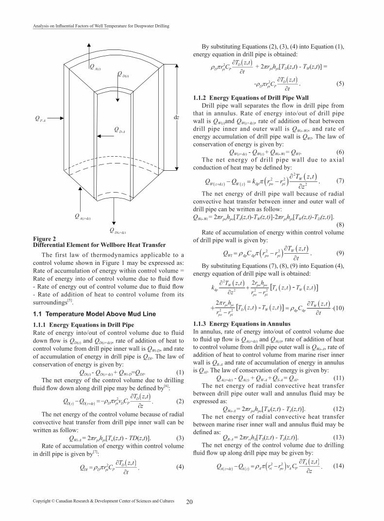
2. MODEL SIMULATIONThe computer code was subsequently employed to validate the temperature model. Parameters used for the simulations is shown in Table 1.
22Copyright © Canadian Research & Development Center of Sciences and Cultures
Analysis on Influential Factors of Well Temperature for Deepwater Drilling
Table 1Basic Data
Water depth Well depth Riser OD Wellbore diameter Drillpipe OD
1,152 m 3,000 m 501.65 mm 215.9 mm 127 mm
Circulation rate Inlet temperature Water temperature at surface Water temperature at seabed Geothermal gradient
2 m3/min 22 ℃ 23 ℃ 4.34 ℃ 2.5 ℃/100 m
Table 2Physical Parameters of Mediums
Physical parameters Drilling fluid Drill string Cement Formation
Density (kg/m3) 1,300 7,800 1,025 2,640
Specific heat [J/(kg·℃)] 1,675 400 3,890 837
Thermal conductivity [w/(m·℃)] 1.73 43.75 0.58 2.25
The effects of circulation hours, drilling fluid specific heat, thermal conductivity, density, flow rate and geothermal gradient on annulus temperature distribution are shown in Figures 3-8.
0
500
1,000
1,500
2,000
2,500
3,000
3,500
4,000
4,500
0 20 40 60
Dep
th (m
)
Temperature (℃)
0.5 h1 h2 h4 h8 h
Figure 3Temperature in Annulus With Well Depth for Different Circulation Times
0
500
1,000
1,500
2,000
2,500
3,000
3,500
4,000
4,500
0 20 40 60
Dep
th (m
)
Temperature (℃)
1.683.55
J/(kg·℃)J/(kg·℃)
J/(kg·℃)
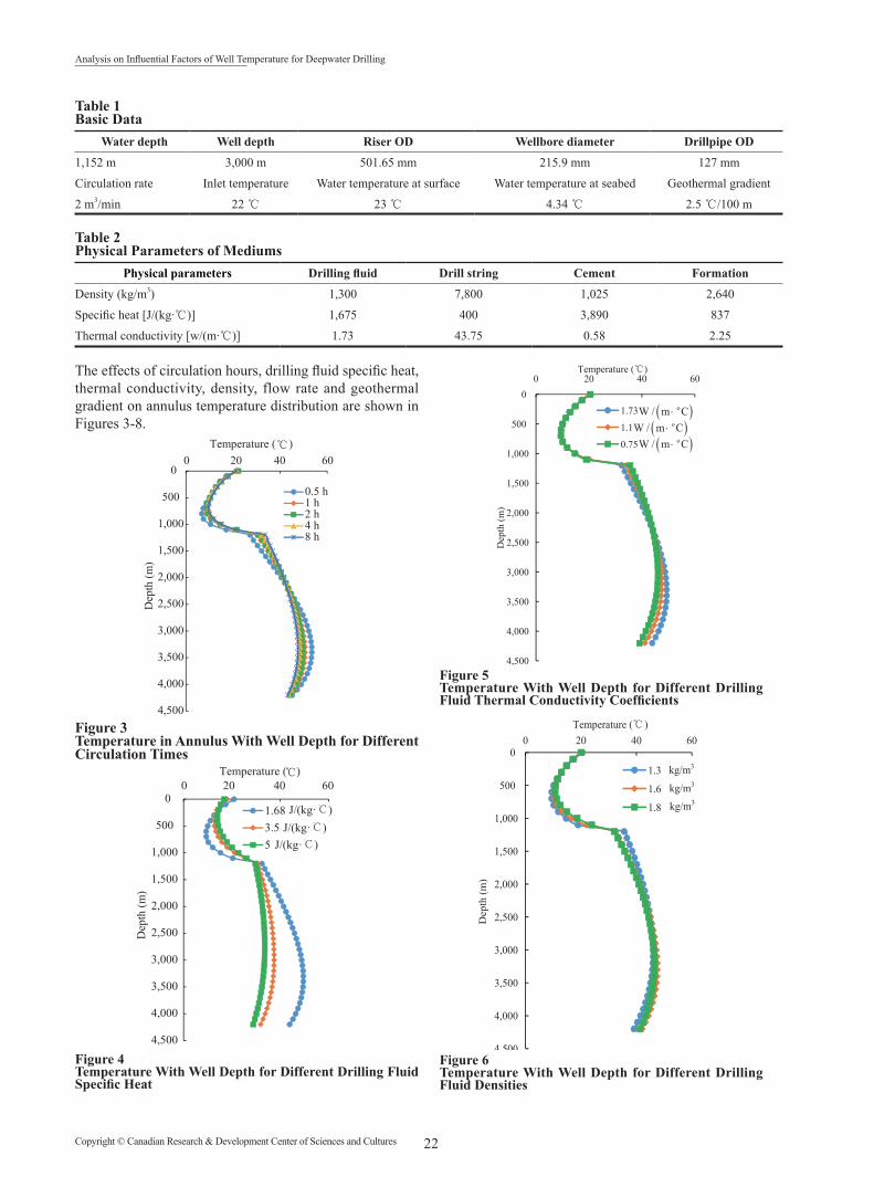
Figure 4Temperature With Well Depth for Different Drilling Fluid Specific Heat
0
500
1,000
1,500
2,000
2,500
3,000
3,500
4,000
4,500
0 20 40 60
Dep
th (m
)
Temperature (℃)
1.73
1.1
0.75
( )oW / m C⋅
( )oW / m C⋅
( )oW / m C⋅
0
500
1,000
1,500
2,000
2,500
3,000
3,500
4,000
4,500
0 20 40 60
Dep
th (m
)
Temperature (℃ )
1.3
1.6
1.8
kg/m3
kg/m3
kg/m3
Figure 5Temperature With Well Depth for Different Drilling Fluid Thermal Conductivity Coefficients
0
500
1,000
1,500
2,000
2,500
3,000
3,500
4,000
4,500
0 20 40 60
Dep
th (m
)
Temperature (℃)
1.73
1.1
0.75
( )oW / m C⋅
( )oW / m C⋅
( )oW / m C⋅
0
500
1,000
1,500
2,000
2,500
3,000
3,500
4,000
4,500
0 20 40 60
Dep
th (m
)
Temperature (℃ )
1.3
1.6
1.8
kg/m3
kg/m3
kg/m3
Figure 6Temperature With Well Depth for Different Drilling Fluid Densities
23 Copyright © Canadian Research & Development Center of Sciences and Cultures
SUN Shihui; YAN Tie; BI Xueliang; YU Guoqing (2015). Advances in Petroleum Exploration and Development, 9(2), 19-24
0
500
1,000
1,500
2,000
2,500
3,000
3,500
4,000
4,500
0 10 20 30 40 50D
epth
(m)
Temperature (℃)
20 l/s
32 l/s
40 l/s
0
500
1,000
1,500
2,000
2,500
3,000
3,500
4,000
4,500
0 20 40 60
Dep
th (m
)
Temperature (℃ )
2 ℃ /100 m
2.5 ℃ /100 m
3 ℃ /100 m
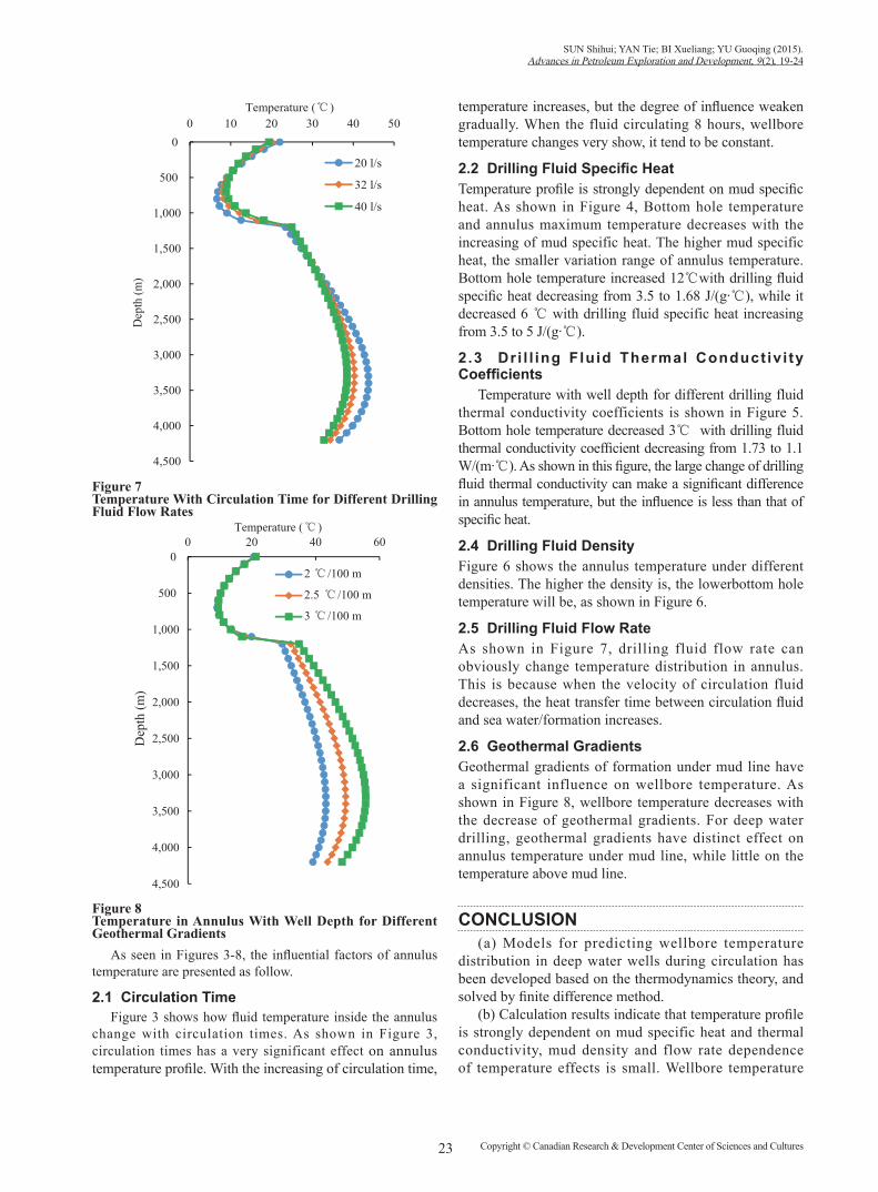
Figure 7Temperature With Circulation Time for Different Drilling Fluid Flow Rates
0
500
1,000
1,500
2,000
2,500
3,000
3,500
4,000
4,500
0 10 20 30 40 50
Dep
th (m
)
Temperature (℃)
20 l/s
32 l/s
40 l/s
0
500
1,000
1,500
2,000
2,500
3,000
3,500
4,000
4,500
0 20 40 60
Dep
th (m
)
Temperature (℃ )
2 ℃ /100 m
2.5 ℃ /100 m
3 ℃ /100 m
Figure 8Temperature in Annulus With Well Depth for Different Geothermal Gradients
As seen in Figures 3-8, the influential factors of annulus temperature are presented as follow.
2.1 Circulation TimeFigure 3 shows how fluid temperature inside the annulus
change with circulation times. As shown in Figure 3, circulation times has a very significant effect on annulus temperature profile. With the increasing of circulation time,
temperature increases, but the degree of influence weaken gradually. When the fluid circulating 8 hours, wellbore temperature changes very show, it tend to be constant.
2.2 Drilling Fluid Specific HeatTemperature profile is strongly dependent on mud specific heat. As shown in Figure 4, Bottom hole temperature and annulus maximum temperature decreases with the increasing of mud specific heat. The higher mud specific heat, the smaller variation range of annulus temperature. Bottom hole temperature increased 12℃with drilling fluid specific heat decreasing from 3.5 to 1.68 J/(g·℃), while it decreased 6 ℃ with drilling fluid specific heat increasing from 3.5 to 5 J/(g·℃).
2.3 Dr i l l ing Fluid Thermal Conduct iv i ty Coefficients
Temperature with well depth for different drilling fluid thermal conductivity coefficients is shown in Figure 5. Bottom hole temperature decreased 3℃ with drilling fluid thermal conductivity coefficient decreasing from 1.73 to 1.1 W/(m·℃). As shown in this figure, the large change of drilling fluid thermal conductivity can make a significant difference in annulus temperature, but the influence is less than that of specific heat.
2.4 Drilling Fluid DensityFigure 6 shows the annulus temperature under different densities. The higher the density is, the lowerbottom hole temperature will be, as shown in Figure 6.
2.5 Drilling Fluid Flow RateAs shown in Figure 7, drilling fluid flow rate can obviously change temperature distribution in annulus. This is because when the velocity of circulation fluid decreases, the heat transfer time between circulation fluid and sea water/formation increases.
2.6 Geothermal GradientsGeothermal gradients of formation under mud line have a significant influence on wellbore temperature. As shown in Figure 8, wellbore temperature decreases with the decrease of geothermal gradients. For deep water drilling, geothermal gradients have distinct effect on annulus temperature under mud line, while little on the temperature above mud line.
CONCLUSION(a) Models for predicting wellbore temperature
distribution in deep water wells during circulation has been developed based on the thermodynamics theory, and solved by finite difference method.
(b) Calculation results indicate that temperature profile is strongly dependent on mud specific heat and thermal conductivity, mud density and flow rate dependence of temperature effects is small. Wellbore temperature

24Copyright © Canadian Research & Development Center of Sciences and Cultures
Analysis on Influential Factors of Well Temperature for Deepwater Drilling
is dynamic, temperature increases with the increase of circulating time, and tend to be constant when circulating time reaches a certain value. And geothermal gradients of formation under mud line have a significant influence on wellbore temperature.
REFERENCES[1] Baker, J. W., & Gomez, R. K. (1989). Formation of hydrates
during deepwater drilling operations. JPZ, 41(3), 297-301. [2] Hale, A. H., & Dewan, A. K. R. (1990). Inhibition of gas
hydrates in deepwater drilling. SPE Drilling Engineering, 5(2), 109-115.
[3] Gao, S., House, W., & Chapman, W. (2005, May). Characterization of hydrate formation in black oil using NMR. Paper presented at 2005 Offshore Technology Conference, Houston, TX, USA.
[4] Romero J., & Touboul, E. (1998, September). Temperature prediction for deepwater wells : A f ield validated methodology. Paper presented at SPE Annual Technical Conference and Exhibition, New Orleans, Louisiana.
[5] Incropera, F. P., & De Witt, D. P. (1990). Fundamentals of heat and mass transfer (3rd ed.). USA: John Wiley & Sons.
[6] Welty, J. R., & Wicks, C. E., & Wilson, R. E. (1984). Fundamentals of momentum, heat, and mass transfer (3rd ed.). USA: John Wiley & Sons.
[7] Eirik, K., & Bernt, S. (1999, September). Optimization of mud temperature and fluid models in offshore applications. Paper presented at Offshore Europe Oil and Gas Exhibition and Conference, Aberdeen, United Kingdom.
[8] Hasan, A. R., & Kabir, C. S. (1994). Aspects of wellbore heat transfer during two-phase flow. SPE Production & Facilities, 9(3), 211-216.
[9] Hansen, A. R. (1991, October). Heat transfer during two-phase flow in wellbores: Part I, formation temperature. Paper presented at SPE Annual Technical Conference and Exhibition Dallas, TX, USA.