Embed Size (px)
Citation preview
1A(u[Npot�
twnanotpmbptatb[diwfb
mogt
1800 J. Opt. Soc. Am. B/Vol. 25, No. 11 /November 2008 Ilic et al.
Analysis of tunneling times in absorptive anddispersive media
Igor Ilic,1 Petra P. Beli~ev,1 Vitomir Milanovic,2 and Jelena Radovanovic2,*1Vin~a Institute of Nuclear Sciences, P.O.B. 522, 11001 Belgrade, Serbia
2Faculty of Electrical Engineering, University of Belgrade, Bulevar kralja Aleksandra 73, 11120 Belgrade, Serbia*Corresponding author: [email protected]
Received June 17, 2008; accepted August 12, 2008;posted August 28, 2008 (Doc. ID 97231); published October 9, 2008
Tunneling times in absorptive and dispersive media are considered, as are the relations between them. Groupdelay and dwell time are used as the most appropriate tunneling time characterizations. A general expressionthat relates these two quantities, valid for all linear media (with both positive and negative index of refrac-tion), is derived, but particular attention is given to negative index metamaterials. The example of a nonmag-netic, lossless medium with dispersive surroundings was chosen to illustrate the derivation of self-interferencetime. Existence of the Hartman effect and negative group delay in a certain range of frequencies, in metama-terials, is numerically verified. © 2008 Optical Society of America
OCIS codes: 240.7040, 310.6860.
NDgWn
2Wabito
f�taniao
a
. INTRODUCTIONrtificial materials, called negative index metamaterials
NIMs), have been produced recently and manifest somenusual properties within a certain range of frequencies
1,2]. This property has been achieved in single-negativeIMs (SN-NIMs), which have negative permittivity orermeability and satisfy the condition �R�I+�I�R�0 [1]r in double-negative NIMs (DN-NIMs), which have nega-ive real parts of permittivity and permeability (�R�0,R�0) [2].In numerous experiments [3,4] it has been shown that
he tunneling electromagnetic pulses through an obstacleith positive index of refraction may travel at superlumi-al, or even negative, group velocities in regions ofnomalous dispersion �n /���0. Recent experiments andumerical calculations show that this phenomenon is alsone of the key properties of NIMs [5]. This implies thathe peak of the transmitted wave packet would emergerior to the peak of the incident wave packet entering theedium. These do not, as it may seem, violate causality,
ecause energy propagation velocity inside the medium isositive and less than the speed of light in vacuum. Twounneling-time definitions, group delay and dwell time,re considered to be the most appropriate to characterizehe tunneling of electromagnetic waves [6]. The relationetween them was a subject of debates for a long time7,8], until Winful suggested a relation in which a groupelay is a sum of the dwell time and a term called self-nterference time [9], which represents the time that aave packet spends interfering with the reflected wave in
ront of an obstacle. This time is nonzero only when theackground medium is dispersive.However, this relation is valid only for an obstacleade of nonmagnetic material ��R=1� with positive index
f refraction. The goal of this paper is to derive a more-eneral relation between the group delay and the dwellime that is valid for all materials, including NIMs.
0740-3224/08/111800-5/$15.00 © 2
umerical calculations were carried out for differentN-NIMs and some special cases. The link between theroup delay and the dwell time will be compared toinful’s expression considering the case of a lossless
onmagnetic medium.
. THEORETICAL CONSIDERATIONSe consider an obstacle of homogeneous, dispersive and
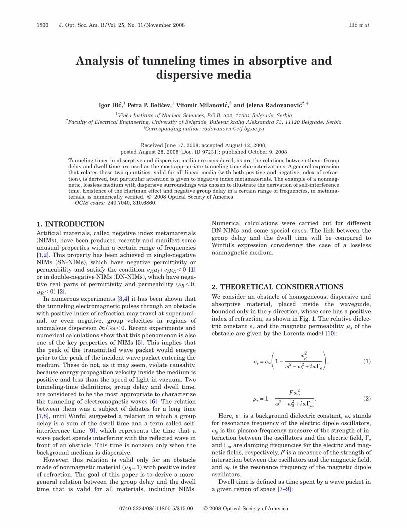
bsorptive material, placed inside the waveguide,ounded only in the y direction, whose core has a positivendex of refraction, as shown in Fig. 1. The relative dielec-ric constant �s and the magnetic permeability �s of thebstacle are given by the Lorentz model [10]:
�s = ���1 −�p
2
�2 − �r2 + i��e
� , �1�
�s = 1 −F�0
2
�2 − �02 + i��m
. �2�
Here, �� is a background dielectric constant, �r standsor resonance frequency of the electric dipole oscillators,p is the plasma-frequency measure of the strength of in-
eraction between the oscillators and the electric field, �end �m are damping frequencies for the electric and mag-etic fields, respectively, F is a measure of the strength of
nteraction between the oscillators and the magnetic field,nd �0 is the resonance frequency of the magnetic dipolescillators.
Dwell time is defined as time spent by a wave packet ingiven region of space [7–9]:
008 Optical Society of America
wb
e
iHftfi
(tHr
wltsdws
wp
eHatg
wa
r
ig
wo
st
Ilic et al. Vol. 25, No. 11 /November 2008 /J. Opt. Soc. Am. B 1801
�d =W
Pin, �3�
here W is the stored electromagnetic energy inside thearrier and Pin is the time-averaged incident power.For dispersive and absorptive media, electromagnetic
nergy density is given by [10]
� =�0
4�eff�E2� +
�0
4�eff�H2�, �4�
n terms of complex electric and magnetic fields E� and H� .ere, �eff=�R+2��I /�e and �eff=�R+2��I /�m are the ef-
ective permittivity and permeability, where �R, �R arehe real parts, and �I, �I are the imaginary parts ofrequency-dependent relative permittivity and permeabil-ty of dispersive media, respectively.
We use the previous equation, which is actually Eq.14) from [10], as the starting point for further deriva-ions. Considering only the TE modes and inserting theelmholtz equation, the expression for stored energy
eads
W =�0S
4����eff�
0
L
�Ey�2dx −S�eff�0
2�2��s�2�0Im�R��E0�2
−S�eff
4�2��s�2�0K1, �5�
here S is the cross-section surface, L is the barrierength, �E0� is the incident electric field amplitude, R ishe reflection coefficient, and �0=�k0
2�b�b−2, where k0tands for a wave number in vacuum, �b and �b are theielectric permittivity and magnetic permeability of aaveguide, respectively, and is a wave propagation con-
tant. Also,
����eff = �eff +�eff Re��s�s�
��s�2, �6�
K1 = Re���s − �b�Ey*
Ey�
��x�x=0
+ ��b − �s�Ey*
Ey�
��x�x=L� , �7�
here ��d/dx. For details on obtaining Eqs. (5)–(7)lease see Appendix A.
Fig. 1. The model.
Further, subtracting the conjugate of the Helmholtzquation multiplied by dEy /d� from the derivative of theelmholtz equation, with respect to � multiplied by Ey
*,nd integrating this expression along the barrier, the in-egral in Eq. (5) can be derived to be a function of theroup delay:
�0
L
�Ey�2dx =2�0�g + 2
d�0
d�Im�R�
1
k02
dk02
d�Re��s
2� +d Re��s
2�
d�
�E0�2
−
2k02�
0
L
Im��s�s�Im�dEy*
d�Ey�dx − K2
1
k02
dk02
d�Re��s
2� +d Re��s
2�
d�
,
�8�
here �s2=k0
2�s�s−k02�b�b sin2 , and is the incident
ngle, while group delay and K2 are defined as
�g = �T�2d�0
d�+ �R�2
d�r
d�, �9�
K2 = Re���s − �b�Ey�
��x�
dEy*
d�
−d
d���s − �b�
Ey�
��x�Ey*�
x=0
+ Re���b − �s�Ey�
��x�
dEy*
d�−
d
d�
���b − �s�Ey�
��x�Ey*�
x=L
, �10�
espectively, where �0=�t+�0L , R= �R �ei�r , T= �T �ei�t.If the obstacle is lossless, the terms d�0 /d� and d�r /d�
n Eq. (9) become equal. The absorption A for TE modes isiven by
A =1
�0�E0�2�0
L Im��s2��Ey�2 − Im���
�Ey�Ey
*�dx, �11�
here �R�2+ �T�2+A=1. The time-averaged incident power,btained from the complex Poynting theorem, is
Pin =�0�0c2S
2��E0�2. �12�
Now it is possible to obtain the expression that de-cribes a generalized relation between the dwell time andhe group delay in the barrier:
w
tEa
etlTntt
f�tastytdbgi
3Tdo==a3aqItG
sttsgeoptl[er
arr�=Sprn
Foa
1802 J. Opt. Soc. Am. B/Vol. 25, No. 11 /November 2008 Ilic et al.
�d =
�g +1
�0
d�0
d�Im�R�
K3−
�eff
���s�2Im�R�
+
K2 + 2k02�
0
L
Im��s�s�Im�dEy*
d�Ey�dx
2�0c2�E0�2
�����eff� 1
k02
dk02
d�Re��s
2� +d Re��s
2�
d��
−�eff
2��0��s�2�E0�2K1, �13�
here
K3 =1
����eff�2K4 + �
dK4
d�� , �14�
K4 = Re��s�s − �b�b sin2 �. �15�
The equivalent procedure for the TM modes leads tohe analog of Eq. (13), with the substitutions E0→H0,y→Hy, �eff→�eff, and �s→�s. These substitutions arelso valid for absorption.In order to compare our results with the existing mod-
ls we will consider some special cases. Winful [9] impliedhat in lossless dielectric media ��e=�m=0�, the group de-ay is a sum of the dwell and the self-interference time.his relation stands only for nonmagnetic materials withormal incidence, i.e., �s=1 and =0. Under these condi-ions, and with the background dielectric constant equalo 1, Eq. (13) gives
�g = �d + �i �16�
or both TE and TM modes. Here, �i=Im�R� /�− �1/�0��d�0 /d��Im�R� is the self-interference time. It describes
he effects of dispersion in the surrounding medium innalogy with the quantum tunneling [11]. For a disper-ionless surrounding medium, �i is equal to zero becausehe waveguide width in the x direction is not limited,ielding �0
2= ��2 /c2��b�b cos2 . Thus, the self-interferenceerm vanishes. However, if the waveguide width in the xirection is limited (as described in [9]), then values of ecome quantized in terms of m /a, where m is an inte-er and a is the waveguide width, and the self-nterference time �i remains finite [12].
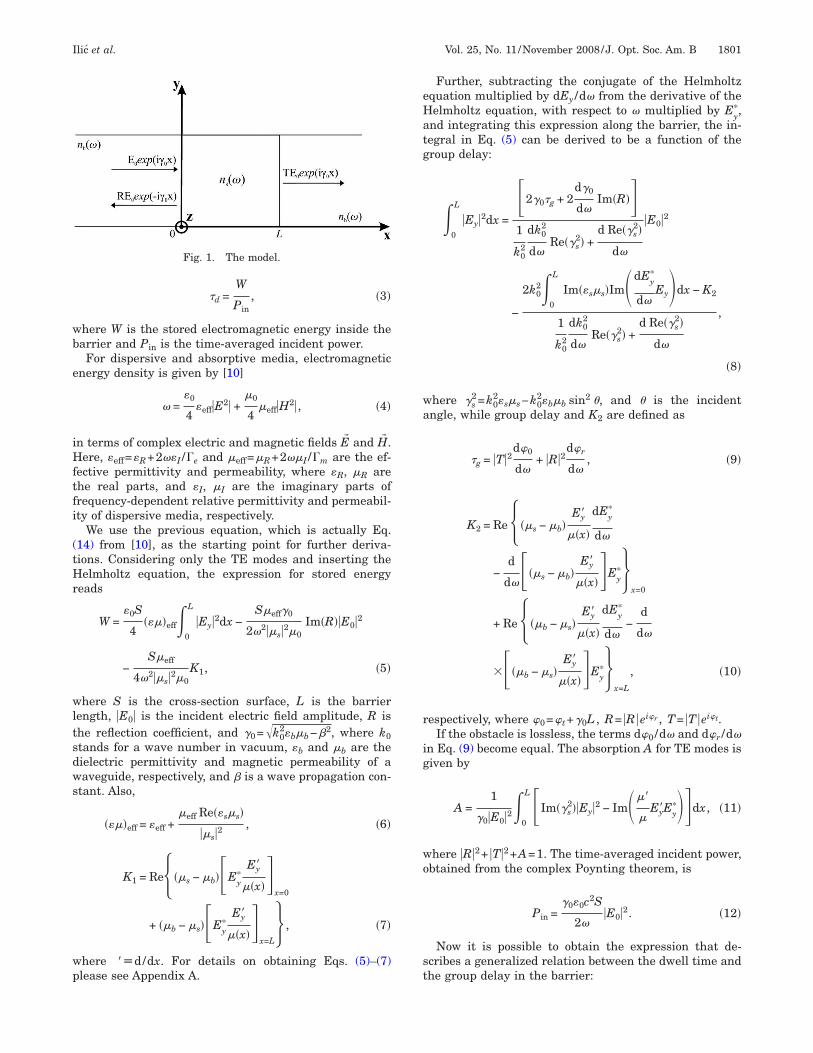
. NUMERICAL RESULTShe numerical calculations will be performed for severalifferent cases. The first case comprises the propagationf TE modes through the obstacle placed in air ��b=�b1�, which has the following parameters [10]: �p10 GHz, �r=0, �0=4 GHz, F=1.25, ��=1, �e=0.05�p,nd �m=0.05�0. The obstacle is left-handed for.52 GHz���6.57 GHz. Figure 2 shows the dwell timend the group delay dependences on incident wave fre-uencies for three different incident angles and L=1cm.t is important to mention that incident angles largerhan /6 lead to a phenomenon known as the negativeoos–Hänchen shift [13]. The absorption has a shape
imilar to that of the dwell time, unlike group delay. Bothhe dwell time and the absorption have local maxima athe boundaries of the frequency range in which the ob-tacle shows left-handedness. On the other hand, theroup delay has local minima at these frequencies, and itven becomes negative in some cases. For =0, the peaksf all quantities disappear at �=6 GHz, leaving only theeaks at resonant frequency �0. Also, the absorption andhe dwell time both saturate with increasing obstacleength. This phenomenon, known as the Hartman effect3,4,14], is explained on the basis of saturation of storednergy with increasing length of an obstacle [9]. Identicalesults are obtained for propagation of TM modes.
The next case entails propagation of TE modes throughn obstacle made with left-handed features in the opticalange and surrounded by a dispersive waveguide. The pa-ameters of the obstacle material are [2]�p=2700 THz,r=0, �0=2300 THz, F=0.052, ��=3.1, �e=35 THz, �m35 THz and L=1 �m. The waveguide core is made ofiO2, which is also transparent in this range. Its relativeermittivity is given by the Sellmeier formula [15], andelative permeability is �b=1. The obstacle is double-egative for wavelengths between 799 nm and 818 nm.
ig. 2. (a) The dwell time and (b) the group delay dependencesn incident radiation frequency for three different incidentngles (=0, /12, and /6).
TtTahfleofc�ptfapqiitp
=i�to
a(trttnt
4IvdbhmstfinriNg
AC=w
Wwf
Fpl
Ilic et al. Vol. 25, No. 11 /November 2008 /J. Opt. Soc. Am. B 1803
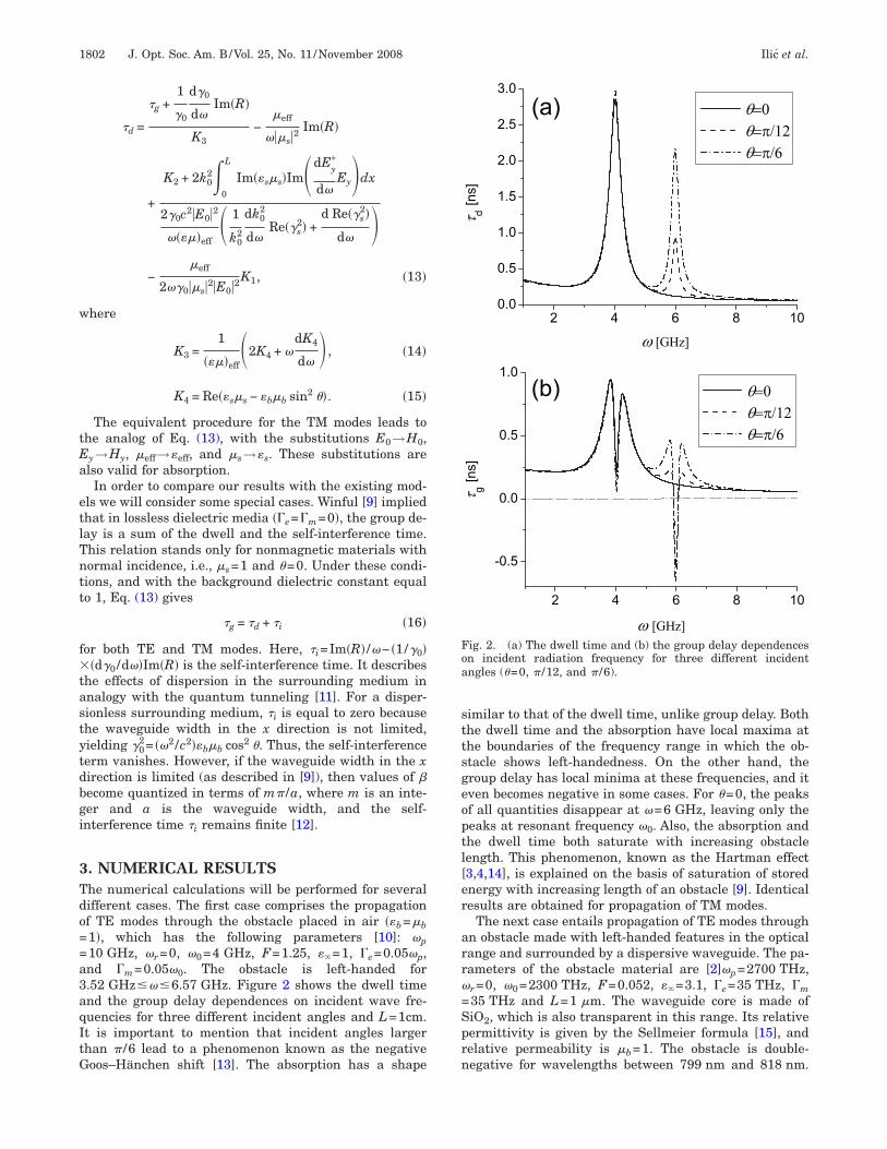
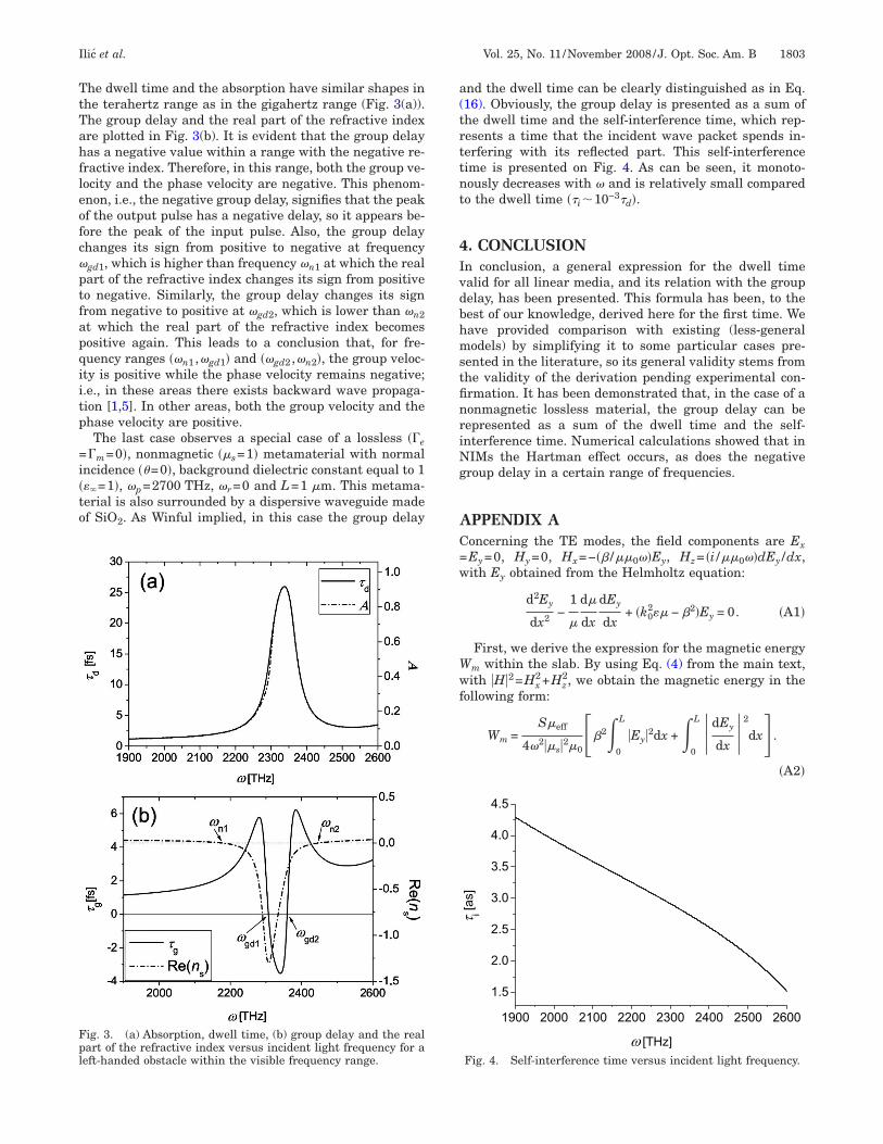
he dwell time and the absorption have similar shapes inhe terahertz range as in the gigahertz range (Fig. 3(a)).he group delay and the real part of the refractive indexre plotted in Fig. 3(b). It is evident that the group delayas a negative value within a range with the negative re-ractive index. Therefore, in this range, both the group ve-ocity and the phase velocity are negative. This phenom-non, i.e., the negative group delay, signifies that the peakf the output pulse has a negative delay, so it appears be-ore the peak of the input pulse. Also, the group delayhanges its sign from positive to negative at frequencygd1, which is higher than frequency �n1 at which the realart of the refractive index changes its sign from positiveo negative. Similarly, the group delay changes its signrom negative to positive at �gd2, which is lower than �n2t which the real part of the refractive index becomesositive again. This leads to a conclusion that, for fre-uency ranges ��n1 ,�gd1� and ��gd2 ,�n2�, the group veloc-ty is positive while the phase velocity remains negative;.e., in these areas there exists backward wave propaga-ion [1,5]. In other areas, both the group velocity and thehase velocity are positive.The last case observes a special case of a lossless ��e
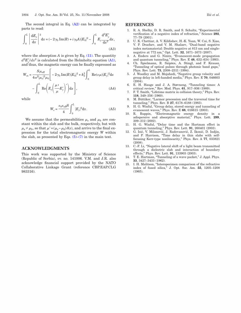
�m=0�, nonmagnetic ��s=1� metamaterial with normalncidence �=0�, background dielectric constant equal to 1��=1�, �p=2700 THz, �r=0 and L=1 �m. This metama-erial is also surrounded by a dispersive waveguide madef SiO2. As Winful implied, in this case the group delay
ig. 3. (a) Absorption, dwell time, (b) group delay and the realart of the refractive index versus incident light frequency for aeft-handed obstacle within the visible frequency range.
nd the dwell time can be clearly distinguished as in Eq.16). Obviously, the group delay is presented as a sum ofhe dwell time and the self-interference time, which rep-esents a time that the incident wave packet spends in-erfering with its reflected part. This self-interferenceime is presented on Fig. 4. As can be seen, it monoto-ously decreases with � and is relatively small comparedo the dwell time ��i 10−3�d�.
. CONCLUSIONn conclusion, a general expression for the dwell timealid for all linear media, and its relation with the groupelay, has been presented. This formula has been, to theest of our knowledge, derived here for the first time. Weave provided comparison with existing (less-generalodels) by simplifying it to some particular cases pre-
ented in the literature, so its general validity stems fromhe validity of the derivation pending experimental con-rmation. It has been demonstrated that, in the case of aonmagnetic lossless material, the group delay can beepresented as a sum of the dwell time and the self-nterference time. Numerical calculations showed that inIMs the Hartman effect occurs, as does the negativeroup delay in a certain range of frequencies.
PPENDIX Aoncerning the TE modes, the field components are ExEy=0, Hy=0, Hx=−� /��0��Ey, Hz= �i /��0��dEy /dx,ith Ey obtained from the Helmholtz equation:
d2Ey
dx2 −1
�
d�
dx
dEy
dx+ �k0
2�� − 2�Ey = 0. �A1�
First, we derive the expression for the magnetic energym within the slab. By using Eq. (4) from the main text,ith �H�2=Hx
2+Hz2, we obtain the magnetic energy in the
ollowing form:
Wm =S�eff
4�2��s�2�02�
0
L
�Ey�2dx +�0
L �dEy
dx �2
dx .
�A2�
Fig. 4. Self-interference time versus incident light frequency.
p
wda
w
s�pt
AT(aC9
R
1
1
1
1
1
1
1804 J. Opt. Soc. Am. B/Vol. 25, No. 11 /November 2008 Ilic et al.
The second integral in Eq. (A2) can be integrated byarts to read:
�0
L �dEy
dx �2
dx = �− 2�0 Im�R� + i�0A��E0�2 −�0
L
Ey
d2Ey*
dx2dx,
�A3�
here the absorption A is given by Eq. (11). The quantity2Ey
* /dx2 is calculated from the Helmholtz equation (A1),nd thus, the magnetic energy can be finally expressed as
Wm =S�eff
4�2��s�2�0− 2�0 Im�R��E0�2 + k0
2�0
L
Re�����Ey�2dx
−�0
L
Re�Ey����
Ey��*�dx , �A4�
hile
We =�0�effS
4 �0
L
�Ey�2dx. �A5�
We assume that the permeabilities �s and �b are con-tant within the slab and the bulk, respectively, but withs��b, so that ��= ��s−�b���x�, and arrive to the final ex-ression for the total electromagnetic energy W withinhe slab, as presented by Eqs. (5)–(7) in the main text.
CKNOWLEDGMENTShis work was supported by the Ministry of Science
Republic of Serbia), ev. no. 141006. V.M. and J.R. alsocknowledge financial support provided by the NATOollaborative Linkage Grant (reference CBP.EAP.CLG
83316).EFERENCES1. R. A. Shelby, D. R. Smith, and S. Schultz, “Experimental
verification of a negative index of refraction,” Science 292,77–79 (2001).
2. U. K. Chettiar, A. V. Kildishev, H.-K. Yuan, W. Cai, S. Xiao,V. P. Drachev, and V. M. Shalaev, “Dual-band negativeindex metamaterial: Double negative at 813 nm and single-negative at 772 nm,” Opt. Lett. 32, 1671–1673 (2007).
3. A. Enders and G. Nimtz, “Evanescent-mode propagationand quantum tunneling,” Phys. Rev. E 48, 632–634 (1993).
4. Ch. Spielmann, R. Szipöcs, A. Stingl, and F. Krausz,“Tunneling of optical pulses through photonic band gaps,”Phys. Rev. Lett. 73, 2308–2311 (1994).
5. J. Woodley and M. Mojahedi, “Negative group velocity andgroup delay in left-handed media,” Phys. Rev. E 70, 046603(2004).
6. E. H. Hauge and J. A. Støvneng, “Tunneling times: Acritical review,” Rev. Mod. Phys. 61, 917–936 (1989).
7. F. T. Smith, “Lifetime matrix in collision theory,” Phys. Rev.118, 349–356 (1960).
8. M. Büttiker, “Larmor precession and the traversal time fortunneling,” Phys. Rev. B 27, 6178–6188 (1983).
9. H. G. Winful, “Group delay, stored energy and tunneling ofevanescent waves,” Phys. Rev. E 68, 016615 (2003).
0. R. Ruppin, “Electromagnetic energy density in aadispersive and absorptive material,” Phys. Lett. 299,309–312 (2002).
1. H. G. Winful, “Delay time and the Hartman effect inquantum tunneling,” Phys. Rev. Lett. 91, 260401 (2003).
2. G. Isic, V. Milanovic, J. Radovanovic, Z. Ikonic, D. Indjin,and P. Harrison, “Time delay in thin slabs with self-focusing Kerr-type nonlinearity,” Phys. Rev. A 77, 033821(2008).
3. C.-F. Li, “Negative lateral shift of a light beam transmittedthrough a dielectric slab and interaction of boundaryeffects,” Phys. Rev. Lett. 91, 133903 (2003).
4. T. E. Hartman, “Tunneling of a wave packet,” J. Appl. Phys.33, 3427–3433 (1962).
5. I. H. Malitson, “Interspecimen comparison of the refractiveindex of fused silica,” J. Opt. Soc. Am. 55, 1205–1208(1965).