Embed Size (px)
Citation preview

Analysis of the Structure and Design Relationship between
Contemporary Extensions and Remodeled Masonry
Buildings
Damla Mısırlısoy
Submitted to the
Institute of Graduate Studies and Research
in partial fulfillment of the requirements for the Degree of
Master of Science
in
Architecture
Eastern Mediterranean University
June 2011
Gazimağusa, North Cyprus

Approval of the Institute of Graduate Studies and Research
Prof. Dr. Elvan Yılmaz
Director
I certify that this thesis satisfies the requirements as a thesis for the degree of Master
of Science in Architecture.
Assoc. Prof. Dr. Özgür Dinçyürek
Chair, Department of Architecture
We certify that we have read this thesis and that in our opinion it is fully adequate in
scope and quality as a thesis for the degree of Master of Science in Architecture.
Assoc. Prof. Dr. Yonca Hürol Asst. Prof. Dr. Kağan Günçe
Co-Supervisor Supervisor
Examining Committee
1. Prof. Dr. Kutsal Öztürk
2. Assoc. Prof. Dr. Özlem Olgaç Türker
3. Assoc. Prof. Dr. Yonca Hürol
4. Asst. Prof. Dr. Kağan Günçe
5. Asst. Prof. Dr. Zehra Öngül

iii
ABSTRACT
Old buildings are valuable in transferring the culture for further generations. They
need to be sustained for future by renovating and converting. In the adapting process
of these old buildings new extensions are required to create additional spaces
because of the functional changes. In this process, qualities of the existing building
should be preserved but it should not be forgotten that being respectful to the existing
building does not mean to copy the same style.
Masonry structures bring some limitations while adding new extensions however
these challenges make building unique in terms of identity. This research investigates
the relationship between the existing building and its extension in terms of structural
system and design approach. Extensions can be grouped in 5 categories: integrated,
attached, inserted, wrapped and pierced. This categorization is done according to the
location within the existing fabric.
This research focuses on the extensions to masonry buildings; however extensions to
the other types of contemporary buildings are beyond the scope of this study.
Besides, the research is limited to the public buildings such as cultural and
commercial buildings from different countries. The data is collected through analysis
of the buildings which take place in the literature and an empirical research. 20 case
studies are selected randomly from the literature and categorized according to the
location of the extension within the existing building. Secondly, effect of extension
to the structure and the design approach has been examined. Lastly, an empirical

iv
research has been done under the light of the analysis of Kadir Has University. This
campus has been selected as the field study of the thesis. Finally, evaluations of the
results have been discussed in the conclusion.
The study emphasizes the constraints that must be cared in the extension design and
because of this it claims to be a reference for the designers working on existing
fabric. Remodeling is a crucial issue since old buildings are aesthetic, cultural and
economic resources. The main goal of the research is to raise the awareness of the
issue and to create a base for the other researchers as a guideline to develop this
study further.
Keywords: Remodeling, extension, masonry buildings, structural system, design
approach

v
ÖZ
Eski binalar, kültürün gelecek nesillere aktarılması bakımından önemlidir. Bu
binaların yenilenerek varlıklarının sürdürülebilmesi gerekir. Ancak binalarin uyum
sürecinde fonksiyon değişiklerinden dolayı ek yapılar gerekmektedir. Bu süreçte
mevcut yapının özelliklerinin korunması gerekirken, eskiye olan saygının mevcutu
aynen kopyalamak olmadığı da unutulmamalıdır.
Yığma yapılar, yeni eklemeler bakımından yapıya bazı sınırlandırmalar getirir. Aynı
zamanda bu ekler mevcut binayı kimlik bakımından özel kılar. Bu araştırma, yeni ve
eskinin ilişkisini taşıyıcı sistem ve tasarım yaklaşımları bakımından sorgulamaktadır.
Ek yapılar mevcut binadaki yeri bakımından iç içe geçen, bitiştirilen, içine
yerleştirilen, sarmalanan ve delip geçen olarak 5 gruba ayrılmıştır.
Çalışmada yığma binalara yapılan eklere odaklanılmıştır; çağdaş binalara yapılan
ekler çalışmanın dışındadır. Aynı zamanda, kültürel ve ticari bınalar gibi halka açık
mekanlara eklenen yapılar olarak sınırlandırılmıştır. Veriler, kaynaklarda yer alan
örneklerin analizi ve ampirik araştırma yoluyla toplanmıştır. 20 örnek seçilmiş,
mevcut binadaki konumuna göre gruplanmış ve ekin mevcut yapıya taşıyıcı sistem
ve tasarım yaklaşımları bakımından etkisi sorgulanmıştır. Son olarak ise analizler
ışığında, ampirik bir araştırma yapılmıştır. Kadir Has Üniversitesi Cibali Kampüsü
ampirik araştırma olarak incelenmiştir. Sonuç bölümünde ise bu analizlerin sonuçları
ve bulgular tartışılmıştır.

vi
Bu tez, ek yapı tasarımında dikkat edilmesi gereken hususları ortaya koymakta ve
tasarımcılar ve araştırmacılar için bir kaynak oluşturmaktadır. Eski yığma binaların
estetik, kültürel ve ekonomik bakımdan önemli kaynaklar oluşturmasından dolayı,
yeniden modelleme önemli bir konudur. Araştırmanın esas amacı bu konu üzerinde
farkındalık yaratmak ve gelecek araştırmalar için taban oluşturmaktır.
Anahtar Kelimeler: Yeniden modelleme, ek yapı, yığma yapı, taşıyıcı sistem,
tasarım yaklaşımları

vii
ACKNOWLEDGEMENTS
Appreciation is expressed to:
…my parents and my sister for their supports…
…my friends that has kept encouraging me during the whole process…
…Assoc. Prof. Dr. Özlem Olgaç Türker that opens her personal library for my
research…
…Dr. Mehmet Alper who helped me to find necessary information and documents
about the empirical research…
…my co-supervisor Assoc. Prof. Dr. Yonca Hürol which spends her time for me as
well as my supervisor and shares her valuable ideas with me during the all process…
Lastly greatest appreciation is expressed to my supervisor Asst. Prof. Dr. Kağan
Günçe for his trust, encouragement, supports and for his great role in the
development of this research…

viii
DEDICATION
Dedicated to all that believed and supported me with all their heart...

ix
TABLE OF CONTENT
ABSTRACT ................................................................................................................ iii
ÖZ ................................................................................................................................ v
ACKNOWLEDGEMENTS ....................................................................................... vii
DEDICATION .......................................................................................................... viii
LIST OF TABLES ..................................................................................................... xii
LIST OF FIGURES ................................................................................................... xv
1 INTRODUCTION .................................................................................................... 1
1.1 Aims and Objectives of the Study ..................................................................... 1
1.2 Problem Statement ............................................................................................ 1
1.3 Methodology ..................................................................................................... 2
1.4 Limitations ......................................................................................................... 3
2 REMODELING ........................................................................................................ 4
2.1 Remodeling in comparison to other similar concepts ....................................... 4
2.2 Definition of Remodeling .................................................................................. 8
2.3 The significance of remodeling ...................................................................... 12
2.4 Classification of extensions in remodeled buildings according to the location
............................................................................................................................... 14
2.4.1 Integrated with existing building .......................................................... 16
2.4.2 Attached to the existing building .......................................................... 18
2.4.3 Inserted inside the existing building ..................................................... 18
2.4.4 Wrapping the existing building ............................................................. 20
2.4.5 Piercing the existing building................................................................ 21
3 CATEGORIES OF STRUCTURES ....................................................................... 23
3.1 Definition of the Concept of Structure ............................................................ 23

x
3.2 Classification of the Structural Systems .......................................................... 25
3.2.1 Structures with Traditional Origin ........................................................ 26
3.2.1.1 Masonry wall .......................................................................... 27
3.2.1.2 Arch ........................................................................................ 29
3.2.1.3 Vault ....................................................................................... 30
3.2.1.4 Dome ...................................................................................... 31
3.2.2 Contemporary Structure Systems .......................................................... 33
3.2.2.1 Form active structures ............................................................ 33
3.2.2.2 Vector active structures .......................................................... 40
3.2.2.3 Section active structures ......................................................... 44
3.2.2.4 Surface active structures ........................................................ 48
3.3 Structural materials .......................................................................................... 51
3.3.1 Stone ...................................................................................................... 52
3.3.2 Timber ................................................................................................... 52
3.3.3 Reinforced Concrete.............................................................................. 53
3.3.4 Steel ....................................................................................................... 55
3.4 Relationship between structure and material ................................................... 57
4 DESIGN APPROACH ............................................................................................ 59
4.1 Design principles ............................................................................................. 59
4.1.1 Unity ...................................................................................................... 59
4.1.2 Harmony ................................................................................................ 60
4.1.3 Dominance ............................................................................................ 61
4.1.4 Contrast ................................................................................................. 62
4.1.5 Repetition .............................................................................................. 63
4.1.6 Balance .................................................................................................. 64
4.1.7 Proportion- Scale ................................................................................... 64
4.2 Ordering Principles .......................................................................................... 66

xi
4.2.1 Axis ....................................................................................................... 66
4.2.2 Symmetry .............................................................................................. 67
4.2.3 Hierarchy ............................................................................................... 68
4.2.4. Datum ................................................................................................... 69
4.2.5 Rhythm .................................................................................................. 71
4.2.6 Transformation ...................................................................................... 72
4.3 Organization .................................................................................................... 73
4.3.1 Central organization .............................................................................. 73
4.3.2 Linear organization ............................................................................... 74
4.3.3 Radial organization ............................................................................... 74
4.3.4 Cluster organization .............................................................................. 75
4.3.5 Gridal organization................................................................................ 75
4.4 Circulation ....................................................................................................... 76
5 CASE STUDIES ..................................................................................................... 80
5.1 Selection of the case studies ............................................................................ 80
5.2 Method of analysis .......................................................................................... 80
5.3 Analysis of the case studies ............................................................................. 82
5.4 Evaluation of the case studies ....................................................................... 161
6 EMPIRICAL STUDY ........................................................................................... 169
6.1 Selection of the empirical Study ................................................................... 169
6.2 History of the building .................................................................................. 169
6.3 Analysis of the empirical study ..................................................................... 171
6.3 Discussions about the building ...................................................................... 192
7 CONCLUSION ..................................................................................................... 197
REFERENCES ......................................................................................................... 200
APPENDIX .............................................................................................................. 208

xii
LIST OF TABLES
Table 1. Represents properties of extension types ..................................................... 16
Table 2. Classification of structure systems as traditional and contemporary ........... 26
Table 3. Relationship between structure and material ............................................... 58
Table 4. General Information about Documentation center ....................................... 82
Table 5. Analysis of the Documentation Center ........................................................ 83
Table 6. General Information about Tate Modern ..................................................... 86
Table 7. Analysis of Tate Modern ............................................................................. 87
Table 8. Analysis of Archbishopric Museum ............................................................ 90
Table 9. Analysis of Archbishopric Museum ............................................................ 91
Table 10. General information of Ing and Nnh Bank ................................................ 94
Table 11. Analysis of Ing and Nnh Bank ................................................................... 95
Table 12. General information of the Reichstag ........................................................ 98
Table 13. Analysis of the Reichstag ........................................................................... 99
Table 14. General information of the British Museum ............................................ 102
Table 15. Analysis of the Great Court, British Museum.......................................... 103
Table 16. General information of the X’teresa Alternative Art Center ................... 106
Table 17. Analysis of the X’teresa Alternative Art Center ...................................... 107
Table 18. General information of the Glass Music Hall .......................................... 110
Table 19. Analysis of the Glass Music Hall ............................................................. 111
Table 20. General information of the Architectural Documentation Center ........... 114
Table 21. Analysis of the Architectural Documentation Center .............................. 115
Table 22. General information of the Museum of Local History ............................ 118
Table 23. Analysis of the Museum of Local History ............................................... 119
Table 24. General information of the National Museum of Roman Art .................. 122

xiii
Table 25. Analysis of the National Museum of Roman Art .................................... 123
Table 26. General information of the Santa Catherina Market ................................ 126
Table 27. Analysis of the Santa Catherina Market .................................................. 127
Table 28. General information of the Culture and Education Center ...................... 130
Table 29. Analysis of the Culture and Education Center ......................................... 131
Table 30. General information of the Landesusstellung Kärnten ............................ 134
Table 31. Analysis of the Landesusstellung Kärnten ............................................... 135
Table 32. General information of the St. Mary Library ........................................... 138
Table 33. Analysis of the St. Mary Library ............................................................. 139
Table 34. General information of the Rivoli Museum of Contemporary Art .......... 142
Table 35. Analysis of the Rivoli Museum of Contemporary Art ............................. 143
Table 36. General information of the CET Budapest .............................................. 146
Table 37. Analysis of the CET Budapest ................................................................. 147
Table 38. General information Hedmark Museum & Glass Cathedral .................... 150
Table 39. Analysis of the Hedmark Museum and Glass Cathedral ......................... 151
Table 40. General information of Museum of Contemporary Art ........................... 154
Table 41. Analysis of the Museum of Contemporary Art ........................................ 155
Table 42. General information of Billingsgate Market ............................................ 158
Table 43. Analysis of the Billingsgate Market......................................................... 159
Table 44. Represents relationship between case studies and the type of the extension
.................................................................................................................................. 163
Table 45. Representation of factors affecting design and structural approach ........ 164
Table 46. Representation of factors affecting design and structural approach within
the groups ................................................................................................................. 165
Table 47. Representation of factors affecting design and structural approach within
the groups side by side ............................................................................................. 166
Table 48. Different types of extension in the Kadir Has University building ......... 172
Table 49. General information of the Kadir Has University, A and B Block .......... 173

xiv
Table 50. Analysis of the Kadir Has University, A and B blocks ........................... 174
Table 51. General information of the Kadir Has University, The bridge ................ 177
Table 52. Analysis of the Kadir Has University, bridge extension .......................... 178
Table 53. General information of the Kadir Has University, C Block .................... 181
Table 54. Analysis of the Kadir Has University, C block ........................................ 182
Table 55. General information of the Kadir Has University, D Block .................... 185
Table 56. Analysis of the Kadir Has University, D block ....................................... 186
Table 57. General information of the Kadir Has University, Transition spaces ...... 189
Table 58. Analysis of the Kadir Has University, Transition spaces ........................ 190
Table 59. Kadir Has University Building, Site plan and silhouette ......................... 209
Table 60. Kadir Has University Building, first floor plan ....................................... 210

xv
LIST OF FIGURES
Figure 1. Remodeled castle which considered the benchmark of all conversions ..... 11
Figure 2. Remodeled factory ...................................................................................... 11
Figure 3. Inserted piercing bridge into the massive old building ............................... 12
Figure 4. Extension situated within a four mill .......................................................... 13
Figure 5. Significant example of remodeled buildings .............................................. 13
Figure 6. Classification of performance management ............................................... 15
Figure 7. Classification of addition according to the location in the existing building
.................................................................................................................................... 15
Figure 8. Example of integrated type of extension .................................................... 17
Figure 9. Example of attached type of extension ....................................................... 18
Figure 10. Example of inserted type of extension ..................................................... 19
Figure 11. Example of wrapping type extension ....................................................... 20
Figure 12. Example of pierced type of extension ...................................................... 21
Figure 13. Example of the integrated structures ........................................................ 24
Figure 14. Example of separated structures ............................................................... 24
Figure 15. Load distribution of masonry walls .......................................................... 28
Figure 16. Types of arches ......................................................................................... 29
Figure 17. Example of masonry arch ......................................................................... 30
Figure 18. Types of vault ........................................................................................... 30
Figure 19. Example of masonry vault ........................................................................ 31
Figure 20. Types of dome .......................................................................................... 32
Figure 21. Example of masonry dome ....................................................................... 32
Figure 22. Example of cable structure ....................................................................... 35
Figure 23. First cable roof structure ........................................................................... 35

xvi
Figure 24. Example of tent structure .......................................................................... 36
Figure 25. Example of double layer pneumatic structure .......................................... 38
Figure 26. Example of arch structure ......................................................................... 38
Figure 27. Example of contemporary vault structure ................................................. 40
Figure 28. Example of contemporary dome structure ................................................ 40
Figure 29. Example of vector active structures .......................................................... 41
Figure 30. Example of truss structure ........................................................................ 42
Figure 31. Example of space frame structure............................................................. 43
Figure 32. Geodesic domes are projection of icosahedron ........................................ 44
Figure 33. Example of geodesic dome ....................................................................... 44
Figure 34. Example of steel, reinforced concrete and timber frame respectively ...... 47
Figure 35. Example of slab ........................................................................................ 47
Figure 36. Example of waffle slab ............................................................................. 48
Figure 37. Example of folded plate ............................................................................ 49
Figure 38. Example of shell structure ........................................................................ 50
Figure 39. Example of grid shell ................................................................................ 51
Figure 40. Example of stone building ........................................................................ 52
Figure 41. Example of timber .................................................................................... 53
Figure 42. Example of reinforced concrete ................................................................ 54
Figure 43. Example of reinforced concrete ................................................................ 55
Figure 44. Example of steel structure ........................................................................ 56
Figure 45. Example of steel ....................................................................................... 56
Figure 46. Unity between old and new by repetition of similar geometrical shapes . 60
Figure 47. Repetition of character with a little variety to achieve harmony .............. 61
Figure 48. Creating center of interest to achieve dominancy ..................................... 62
Figure 49. Contrast of shape and color ...................................................................... 63
Figure 50. Repetition of forms to achieve unity ........................................................ 63

xvii
Figure 51. Addition is creating informal balance....................................................... 64
Figure 52. Relationship between existing and extension in terms of scale and
proportion ................................................................................................................... 65
Figure 53. Addition over dominating the existing building ....................................... 65
Figure 54. Types of axis ............................................................................................. 67
Figure 55. Example of bilateral symmetry ................................................................. 68
Figure 56. Hierarchy by a unique shape..................................................................... 69
Figure 57. Types of datum ......................................................................................... 69
Figure 58. Example of wrapping plane ...................................................................... 71
Figure 59. Example of Rhythm .................................................................................. 72
Figure 60. Transformation of dome into contemporary architecture ......................... 72
Figure 61. Example of central organization ............................................................... 73
Figure 62. Example of linear organization ................................................................. 74
Figure 63. Example of radial organization ................................................................. 74
Figure 64. Example of cluster organization ............................................................... 75
Figure 65. Example of gridal organization ................................................................ 76
Figure 66. Circulation elements can be used as sculptural elements ......................... 77
Figure 67. Path-space relationship ............................................................................. 78
Figure 68. Ramp addition into an old building as a circulation element ................... 79
Figure 69. Haliç Silluette in 19th
century ................................................................. 169
Figure 70. Tobacco factory before conversion ........................................................ 170
Figure 71. Views before and after conversion ......................................................... 171
Figure 72. Additional floors supported with steel columns ..................................... 194
Figure 73. Construction process of the museum block ............................................ 194
Figure 74. Steel columns are placed in the museum ................................................ 195
Figure 75. Inner courtyard of new addition ............................................................. 196

xviii
STRUCTURE OF THE THESIS
INTRODUCTION
AIMS AND
OBJECTIVES
PROBLEM
STATEMENT
METHODOLOGY LIMITATIONS
THEORETICAL BACKGROUND
REMODELLING CATEGORIES OF
STRUCTURE
DESIGN
APPROACH
COMPARISON OF
METHODS
DEFINITION
SIGNIFICANCE
CLASSIFICATION
STRUCTURE
SYSTEM
MATERIAL
CONNECTION
DESIGN
PRINCIPLES
ORDERING
PRINCIPLES
ORGANIZATION
CIRCULATION
ANALYSIS: ANALYSIS OF 20 CASE STUDIES
FINDINGS AND DISCUSSIONS
EMPIRICAL RESEARCH: KADIR HAS UNIVERSITY IN ISTANBUL
CONCLUSION

1
Chapter 1
INTRODUCTION
1.1 Aims and Objectives of the Study
The design and construction of new buildings have started to decline at the end of the
second millennium, especially in Central Europe. On the other hand; interventions to
existing buildings are becoming more important (Cramer and Breitling, 2007).
Awareness of ecological issues is growing and as Cramer and Breitling (2007) states:
“The thoughtless demolition of old buildings is now perceived not only as an
ecological waste but also the eradication of local identity, of cultural heritage and of
socio-economic values.”
This study focuses on contemporary additions in existing masonry structures. The
purpose of this research is to examine the relationship between existing masonry
buildings and contemporary additions in terms of structure system and design
approach. Although researchers have devoted much attention to adapting buildings,
they have little devoted attention to structure of extensions. Unlike previous studies
that examine only refurbishment and restoration of old buildings, this study focuses
on additional parts and searching their relationship in terms of structure system and
design approach.
1.2 Problem Statement
Reused buildings are valuable in transferring the culture for further generations.
They need to be sustained for future by renovating and converting. While adapting

2
the old buildings to new functions, new additions are required to create spaces.
Different spaces can be created with the help of different structural systems. This
process needs an understanding of the characteristics of the existing buildings in
order to combine them with new structural systems and materials.
Combination of old and new is a problem when remodeling old buildings. This
combination refers physical combination and combination in terms of design.
Masonry buildings bring some limitations to extension design in terms of
appropriateness of structural systems. The relation between structure system and
design of extension is important for aesthetic concerns and sensitivity on
conservation issues. The main goal of the study is to emphasize the constraints that
must be cared in an extension design.
1.3 Methodology
This study is analysis and synthesis type of research with different type of extensions
to existing masonry buildings. The data is collected through analysis of the examples
in the literature and observation of an empirical study step by step:
20 examples of remodeled building are selected and categorized according to the
connection between existing building and additional part as integrated, attached,
inserted, wrapped and pierced.
Secondly, structure system and materials are analyzed in each group and its relation
has been searched. Lastly, effect of additional part has been examined in terms of
design principles, ordering principles, circulation and organization.
Then, an empirical research has been done under the light of the above analysis.
Kadir Has University campus has been selected as the field study of this thesis. The
case studies that have been analyzed in the previous chapter contain only one type of

3
extension. Almost every type of extension, which is identified, exists in the selected
empirical study. The analysis method has been tested through empirical study and
extensions in case studies have been compared with the Kadir Has University
building.
At the end, evaluation of the results had been made in the conclusion.
1.4 Limitations
Extensions can be classified according to the structure system of existing building as:
Structures with traditional origin (masonry)
Buildings with contemporary structural systems
It is divided into two because problem of adding an extension to each type creates
different problems. This research focuses on the extensions to masonry buildings;
however extensions to contemporary buildings are beyond the scope of this study.
There are historic buildings as well as ordinary old buildings in the selected case
studies.
The main goal of this study is to analyze extensions on masonry buildings after
conversions. Thus, the research is limited to public buildings, mostly to the cultural
and commercial, from different countries since there are other extensions to
residential, transportation or gastronomic buildings.

4
Chapter 2
REMODELING
2.1 Remodeling in comparison to other similar concepts
The reuse of an existing building provides a link to our cultural heritage and historic
memory; additionally it is important because it is environmental friendly. The
amount of resources required for reuse is less than those necessary for redevelopment
(Brooker and Stone, 2008).
Orbaşlı (2008) defines adaptive reuse as: “Most buildings will change their use
through their life time; this will invariably necessitate changes to the internal layout
and fabric of the old building. Making changes to a building to accommodate a new
use is often a means of enabling the continued usefulness of a historic building.
However, the appropriateness of the new use to the building fabric and its integrity
does need to be considered.”
Adaptation of a building is the process of transforming an existing building to
accommodate new uses (Brooker and Stone, 2008). As Douglas (2006) determines:
“It means any intervention go beyond maintenance to change its capacity, function or
performance.” It includes alteration, conversion, extension and refurbishment. There
are various reasons of adapting buildings such as conservation and sustainability
(Douglas, 2006).

5
Sustainability: Reuse of an old building is more ecological than erecting a new
building. Razing and redevelopment activities spend more energy; and expose more
waste than adapting the existing building (Douglas, 2006).
Conservation: The decisions to adapt an existing building rather than redevelopment
can be influenced by the cultural and technical aspects. The historic and architectural
significance of existing building can be satisfactory reasons why it should be
sustained (Douglas, 2006).
Charter (1999), defines conservation as: “All the process of looking after a place so
as to retain its cultural significance. It includes maintenance and may according to
circumstances include preservation, restoration, renovation and adaptation and will
commonly be combination of more than of those”. There are a number of different
methods used in the conservation of a structure and there are distinct differences
between each approach:
Preservation: is to maintain a building in its existing form and condition and carrying
out the repairs and maintenance work if it is necessary (Orbaşlı, 2008). It deals
straightforwardly with cultural property. The main aim is to keep the existing
building in its existing condition. Repairs must be undertaken as necessary in order
to avoid from further decays (Craven, 2008).
Restoration: is the method of returning the existing building to its original condition
with using material and techniques from the original period (Brooker and Stone,
2007). While returning the building back to its near original appearance, it is

6
important to provide adequate differentiation between old and new to avoid any
misinterpretation in the future (Orbaşlı, 2008).
Renovation: is the process of renewing and updating the existing building (Brooker
and Stone, 2007).
Adaptive reuse: “Most buildings will change their use through their life time; this
will invariably necessitate changes to the internal layout and fabric of the old
building. Making changes to a building to accommodate a new use is often a means
of enabling the continued usefulness of a historic building. However, the
appropriateness of the new use to the building fabric and its integrity does need to be
considered” (Orbaşli, 2008).
Solutions that applied to the existing building should work with the existing building,
instead of being against it. Sympathetic materials must be used where new additions
are needed. Extension should be constructed either with the past techniques or in
contrast to them. This choice is identified depending on the design. Modern
technology should be used to preserve the existing building where traditional
methods would be harmful (Latham, 2000).
As Orbaşlı (2008) states: “Conservation can involve anything from restoring gilded
decorative moulding on the ceiling of a royal palace or remodeling a former factory
into a new museum, to maintaining the character of a historic quarter while still
allowing it to evolve as a place to live in.”

7
As Brooker and Stone (2007) determine “Remodeling is the process of altering a
building” however the most obvious change is the function, but other interventions
can be made to the existing building such as its structure, circulation routes and its
orientation. While some parts may be demolished, new extensions may be
constructed (Brooker and Stone, 2007).
The old and new can be contrasting or harmonious but in each case the new addition
have to be separated from the old ones with a different identity in order to see the
difference between old and new. The relation between the historical buildings with
the additions is so important that the new extensions have to be appropriate in terms
of material selection, connection details and structure system. The new additions
have to be separated from the old ones that can be removed any time without
destroying the original building.
The forms are affected by the properties of materials from which they are made and
which are influenced for structural element. The process of manufacturing materials
into structural elements also play role in determining the forms of elements for which
they are suitable. Masonry is composed from bringing together individual stones,
bricks or blocks and sticking them together with the mortar to form columns, walls,
arches or vaults. The range of different types of masonry is large due to the variety of
types like brick, stone or concrete blocks (Macdonald, 1994).
The fact that masonry structures are composed of very small basic units makes their
construction relatively straightforward. Subject to the structural constraints, complex
geometries can be produced relatively easily, without the need for sophisticated
techniques and very large structures can be built with the help of these simple means.

8
Other attributes of masonry type materials are that they are durable and can be left
exposed in both the interiors and exteriors of buildings. They are also, in most
location, available locally in some form and do not require to be transported over
long distances. In other words it is an environment friendly material the use of which
must be expected to increase in the future (Macdonald, 1994).
Many high-tech structures are being constructed with contemporary construction
techniques and selection of materials, proposing sustainable design but in the long
term, this is not sustainable. Old buildings are important resources at a time of
increasing environmental consciousness and with necessary maintenance, can
continue to be useful for a very long time (Orbaşlı, 2008). As Jodidio (2007) states:
“Giving new life to old stones and wood is a worthy challenge rather than designing
new buildings”.
Despite these positive effects mentioned above, masonry structures have some
negative effects to the design of the buildings. As structural actions it works as a
whole and makes impossible to take some parts out in the remodeling process so
different solution is required to be produced. Combination of old and new is a
challenging process in masonry buildings, which is analyzed in different categories
in the next part.
2.2 Definition of Remodeling
Remodeling is one of the methods of building conservation. Different methods used
in the conservation of an existing building should be distinguished since there are
different approaches to the problem (Brooker and Stone, 2004).

9
Douglas (2006) states that:”Remodeling is a North American term analogous to
adaptation. It essentially means to make new or restore to former or other state or
use.”
Working in the existing fabric has become an economic and ecological issue. It has
stopped to be only a problem of preserving historical buildings. Resource and
pollution issues are increasing because of decreasing population numbers in the
industrialized nation; as a result, working in existing fabric, remodeling and restoring
old buildings for future use, have become the order of the day. 40 percent of
construction in Central Europe is conversion of old buildings which will go on to
become more important, instead of destroying more green spaces and resources,
accounting for an increasing percentage of the total building volume (Schittich,
2003).
Building in the existing fabric means reusing historically valuable structures, as well
as ordinary buildings. The method for the task ranges from restoration to a creative
conversion or from a simple refurbishment to a functional and aesthetic intervention
for an ecological upgrade (Schittich, 2003).
As the simple reason, conversion is a cheaper and less complicated process than
constructing a new building. Ordinary buildings needed to be preserved, which are
plain, ordinary, low value including some run down buildings. The new interest in
adaptive reuse makes unknown buildings transformed into major landmarks with
some contemporary extensions (Powell, 1999). Saving old buildings is no longer
enough since the aim is transformation rather than preservation, as Powell (1999)

10
indicates: “An architectural transformation approach to creating new form out of old
fabric”.
The remodeling of an existing structure is not new since buildings have been adapted
for new uses in the history. The Roman Arena in France is converted into residence
in the middle ages and become a small town. People built houses in the performance
space and lived in the massive arches of the structure. The Baths of Diocletian in
Rome were converted into a church by Michelangelo and the Great Mosque in
Cordova was remodeled by inserting a new church directly in the middle of its
structure (Brooker and Stone, 2004).
Designers preferred to erect new buildings and focused all their energies on
innovation especially during the classic modern era and gave less importance to old
buildings. This idea has changed today as Schittich (2003) states: “Working with the
given fabric, which imposes necessary constraints on the designer, is one of the most
creative and fascinating tasks in architecture.”
Carlo Scarpa’s refurbishment of the medieval Castelvecchio in Verona (1956- 1964)
was considered the benchmark for all creative conversions (Figure 1). The principle
that Scarpa used in the remodeling was distinct separation through contrasting
materials. His approach has not lost the validity even today and continued to be
repeated in the historical buildings with only one difference that the limits of the
interventions to the historical buildings is becoming blurred, where the designers
interpret the existing fabrics in a more creative way and develop it further (Schittich,
2003).

11
Castelvecchio in Verona
by Carlo Scarpa
View from the top (URL1, 2011)
Castelvecchio in Verona
by Carlo Scarpa
View from the new bridge(URL1, 2011)
Figure 1. Remodeled castle which considered the benchmark of all conversions
Fiat factory in Turin, which was converted to Cultural and Business Center, is one of
the successful approaches of the creative conversions (Figure 2). Renzo Piano’s
approach was to leave the old building untouched from the outside and to
characterize the interior by a seamless merging between old and new, with the
minimized details.
Cultural and Business Centre in Turin (Schittich, 2003)
Figure 2. Remodeled factory
On the other hand, Gunther Domenig has inserted a piercing bridge into the massive
old building which is the Documentation Center in Nuremberg, achieving a practical
use of the old Nazi Rally building (Figure 3). Although its negative historical

12
heritage, it is an important historic building that should be preserved (Schittich,
2003).
Documentation Center in Nuremberg
Exterior view
(Brooker and Stone, 2007)
Documentation Center in Nuremberg
View from the bridge
(Schittich, 2003)
Figure 3. Inserted piercing bridge into the massive old building
2.3 The significance of the remodeling
Re-addressing the meaning and the value of the old building is a difficult question
when remodeling a building. The relationship between the existing and a new
addition is variable according to three constraints: the cultural values, economics of
the project and the approach of the designer. Out of the three, economic constraint is
the most important one. New construction uses enormous amount of energy when
compared with remodeling, which is saving energy (Brooker and Stone, 2004).
As Brooker and Stone (2004) indicates: “In Europe over the last few years, the
architectural and the national press have devoted huge amounts of coverage to a
series of massive remodeling projects”. The Tate Modern in London, a gallery placed
conversion from a power station, The Baltic Art Factory in England, situated within a

13
flour mill (Figure 4) and the re-roofing of the great court in the British Museum was
the three distinctive remodeling projects of the UK.
Baltic Art Factory in England
Exterior view
(Brooker and Stone, 2007)
Baltic Art Factory in England
3D Model
(Brooker and Stone, 2007)
Figure 4. Extension situated within a four mill
The Grand Louvre pyramid (Figure 5) and courtyard and the iconic glass dome of the
Norman Foster located on the German Parliament building are the significant
examples of remodeled buildings (Brooker and Stone, 2004). Both become major
landmarks of the city rather than ordinary historic monuments after conversion and
additions.
Louvre Museum in Paris
View from the courtyard
(Photo: Author)
Louvre Museum in Paris
Interior view
(Photo: Author)
Figure 5. Significant example of remodeled buildings

14
2.4 Classification of extensions in remodeled buildings according to
the locations
As Douglas (2006) states: “An extension is to expand the capacity or volume of a
building, whether vertically by increasing the height/depth; or laterally by expanding
the plan area”. Extensions can be just as complicated as a new building. Beside the
design limitations of working within an existing structure, there are also issues such
as planning, legal and structural issues that should be taken into account. Circulation,
access, structural integrity and choice of materials should be considered (Mornement,
2007).
In an extension design, ambition and an enthusiasm for experimentation can be
motivational forces for designers; it improves usability and value of the existing
building. It is hard to define universal characteristics of a good extension and with
such a variety of types and scales. But essentially a successful extension should
revitalize and enrich the existing building. It is not just the new spaces or adjacent
rooms attached to the existing. It should be the part of the whole composition rather
than a single project. Contemporary ideas and materials can be applied to an existing
building as an opportunity in extension design. More recent buildings can also be
improved with the addition of an extension as well as historic buildings. Extensions
are classified as up and under, back and front, sideways, outdoors and innovative
additions (Mornement, 2007).
Performance management is divided into two as maintenance and adaptation. An
adaptation to a building can be analyzed in three parts: change in function, change in

15
capacity and change in performance (Figure 6) so according to the table, extensions
are classified as lateral and vertical.
(Douglas, 2006)
Figure 6. Classification of performance management
According to the Günçe (2007), addition can be classified as horizontal, vertical,
oblique and combined. In this study extensions are classified according to the
location of the addition within the context of existing building as integrated,
attached, inserted, wrapped and pierced. Ching’s (2002) classification of space
organization creates a base for this research however it is developed and applied for
the relationship between existing building and additional space.
Figure 7. Classification of addition according to the location in the existing building
EXTENSIONS
INTEGRATED
ATTACHED
INSERTED
WRAPPED
PIERCED

16
Table 1. Represents properties of extension types
CLASSIFICATION OF EXTENSIONS ACCORDING TO THE RELATIONSHIP BETWEEN OLD AND NEW
TYPE RELATIONSHIP PROPERTIES
INTEGRATED
Reflection to the outside
Can be seen from elevation
Inserted inside but combined
Annex punched out from
openings or roof.
ATTACHED
HORIZONTAL Added horizontally next to the
existing building
No integration with the existing
Free standing structure
Complete addition can be seen
from outside
VERTICAL Added vertically next to the
existing building
Integration with the existing
Complete addition can be seen
from outside
INSERTED
Interior scale projects
No reflection to the elevation
Defines space within space
WRAPPED
Existing building is surrounded
like an envelope
Provides unity between different
parts of the existing buildings
Old structure cannot be seen
from outside
PIERCED
Linear extension
Reflection to the outside
Inserted inside but combined
Annex punched out from
openings or roof.
LEGEND EXISTING ADDITION
2.4.1 Integrated with existing building
In the process of remodeling the new function of the building may not fit with the
existing space and new spaces is needed to be defined so new structures are added to
the old buildings. In this category the additional part is integrated with the existing
building. The reflection of the addition can be perceived from the outside of the

17
building as contrast with the third category. Some parts of the addition are punched
out from the openings or roof so it can be perceived from outside of the building. It is
again inserted inside but there is integration of old and new.
The distinction between new and old may be achieved using a different form,
orientation or size. The size of the addition should be smaller than the existing, other
wise the old building begins to lose its impact (Ching, 2002).
The other method of creating distinction is to use different material and structure
system while repeating the language of the existing element but it should be taken
into consideration that when combining the new and the old, existing building should
not be crumbled. It is the most challenging type of the extension since structural
integrity of the old building should not be exploited to support the contemporary
insertion (Brooker and Stone, 2007). As shown in Figure 8, existing building has
already been preserved and new additions have punched out from roof and openings.
Tate Modern in London
Exterior view
(Brooker and Stone, 2007)
Tate Modern in London
3D Model
(Brooker and Stone, 2007)
Figure 8. Example of integrated type of extension

18
2.4.2 Attached to the existing building
The second type is an addition which new structure is attached to the existing
building horizontally or vertically without any combination or integration. It can be
attached next to the building with a freestanding structure (Figure 9) or on top of the
building with structural integrations. Complete addition can be perceived from the
outside of the building.
It is mostly used relationship between new and old. There is exact definition of two
spaces with different styles, linked functionally. The new addition may also differ in
form from the existing building in order to strength its image as a freestanding
volume. The contrast of existing and addition creates differences in terms of function
(Ching, 2002). The new addition can be different also with the structural system or
material while repeating the similar form and proportion of the exiting space.
Public Library Extension, Germany
Exterior view
(Brooker and Stone, 2004)
Public Library Extension, Germany
3D Model
(Brooker and Stone, 2004)
Figure 9. Example of attached type of extension
2.4.3 Inserted inside the existing building
Existing space cannot fit to the new function and new additional spaces needed to be
defined. A single striking element is designed to be inserted into the existing space

19
(Brooker and Stone, 2007). Inserted type of extension is mostly seen in interior
architecture scale projects in which new structures added inside the existing building,
mostly defines space within a space. Very close relationships between the existing
buildings are established in inserted interiors. The new addition may contain a
number of different functional and servicing activities that can easily be separated
from the main activity of the building including circulation, meeting rooms or larger
activities such as lecture theatres and conference halls which private spaces is needed
in the building (Brooker and Stone, 2007). Proposed addition can be a plane defines
floors in the building (Figure 10) or can be a volumetric object that defines subspaces
with the existing building which will be discussed in the following chapters as design
approach. The extension cannot be perceived from outside since there is no reflection
to the façade unlike the first type as shown in Figure 10. New floors were added
inside the old building with contemporary structure system and material but it cannot
be perceived from outside. In this type of relationship, addition should be smaller
than the existing building (Ching, 2002). Ching (2002) states that: “To avoid this
situation, the inserted space may share the form of the enveloping shape but be
oriented in a different manner”.
Borusan Cultural Center in Istanbul
Exterior view
(URL2, 2011)
Borusan Cultural Center in Istanbul
Interior view
(URL2, 2011)
Figure 10. Example of inserted type of extension

20
2.4.4 Wrapping the existing building
As Ching (2002) states: “In this type of relationship, the larger enveloping space
serves as a three dimensional field for the existing space”. Instead of razing an old
building and erecting a new one, old vacant buildings are reused. An addition is
needed to wrap the existing building like an envelope to achieve unity between old
and new building masses. As shown in Figure 11, old structure can not be perceived
from the outside of the building so it creates a surprising effect for the people when
they enter inside the building. In the third category the extension can not be
perceived from the outside since there is no reflection, however in this category old
building can not be perceived from outside as a contrast.
Wrapping additions covers the existing building as a shell that is hidden or
camouflaged. A plane is designed to cover the surfaces of the original building which
gives the appearance of a completely new building. The contemporary addition has
qualities that are independent of the original building since its material, structural and
physical characteristics are distinctive (Brooker and Stone, 2007).
Insurance building in Munich
(Schittich, 2003)
Figure 11. Example of wrapping type extension

21
2.5.5 Piercing the existing building
In some cases existing organizations of the buildings do not match with the
requirements of proposed functions so circulation and organization need to be
changed with the help of an addition. As mentioned in the inserted type, the new
addition may contain a number of different functional and servicing activities that
can easily be separated from the main activity of the building including circulation,
meeting rooms or larger activities such as lecture theatres and conference halls which
private spaces is needed in the building (Brooker and Stone, 2007). In the last type, a
linear extension is pierced through the building providing a circulation route inside
the building. It is commonly used in museum conversion. In Archbishopric Museum,
bridge addition is placed in the museum which creates a circulation route for the
visitors (Figure 12).
The existing building effects the new arrangement and the place of the inserted
element but it does not change the structure or size of the original building. It just
reacts to it (Brooker and Stone, 2007). It has similarities with the integrated category
because again some parts of the addition punched out from the openings or roof so it
can be perceive that there is new addition from the elevations.
Archbishopric Museum in Hamar
Interior view
(Brooker and Stone, 2007)
Archbishopric Museum in Hamar
View From the courtyard
(Brooker and Stone, 2007)
Figure 12. Example of pierced type of extension

22
Concept of remodeling has been introduced and compared with the other concept of
conservation in this chapter. Additionally, extensions have been classified according
to the location in the existing building.
In the following chapter, structure has been defined and categorized. Relationship
between structure and material has also introduced.

23
Chapter 3
CATEGORIES OF STRUCTURES
3.1 Definition of the Concept of Structure
From the beginning of their existence, human beings had been interested in structure
systems consciously or not. Like every living organism, people need to resist wind,
earthquake and gravity forces. Thus, shelters were needed to protect human beings
from natural factors like rain, snow, storm and sun as well as attacks of other human
beings and animals. In this sense, the logic of the contemporary structure systems is
not different from the structure of primitive shelters which were built instinctively in
the ancient periods (Türkçü, 2009).
Simply, an architectural structure is the part of the building which withstands the
loads that are imposed on it. A building can be defined as an envelope which
encloses and divides space in order to create shelters for human beings. Walls, floors
and the roof of the building are the surfaces of the envelope which are divided to
resist different types of loadings. External surfaces are subjected to the climatic loads
of snow, wind and rain; however floors are exposed to their own weight and the
gravitational loads of the residents. Structure is provided to prevent the building from
deformation and collapse of the building. It supplies the strength and rigidity to the
building which is needed to prevent a building from collapsing (Macdonald, 1994).
Structural and nonstructural parts of the building can be integrated in some cases so
the location of the structure might not be visible. Igloos, which are the early

24
examples of dome structures, can be shown as an example of these type of
structures. Ice blocks form a self supporting protecting dome acting as structure and
enclosure elements as well.
Igloo (Macdonald, 1994)
Figure 13. Example of the integrated structures
On the other hand, in some cases structural and enclosing elements are separated.
Primitive tents are the examples of separated structures in which protecting envelope
is a skin supported with timber sticks. The envelope is nonstructural and the sticks
are structural which they are separated completely (Macdonald, 1994).
Primitive tents (Macdonald, 1994)
Figure 14. Example of separated structures
There are various types of structures as mentioned which is classified and defined
below.

25
3.2 Classification of the Structural Systems
Basically, there are two types of structure systems: traditional and contemporary
structures, which produce different types of space. Masonry can be defined as
structures with traditional origin which are thick heavy structures with a limited span
that tend to create small spaces while contemporary structures usually allow larger
spans and create free spaces (Brooker and Stone, 2004).
Masonry structures are built up layer by layer from the ground. The length of the
element that spans across the wall limits the size of the space. The choice of the
material is limited as well. For traditional structures stone and brick were the only
available materials. Changes that are made to these types of structures have to
respect the integrity of the structure (Brooker and Stone, 2004). Masonry structures
can be categorized as arch, vault, dome and masonry wall.
Contemporary structures are structure systems which are developed with the
invention of concrete and steel as new structural materials. The 21st century has
brought Libeskind’s fractals and Gehry’s computer generated buildings which have
quit the traditional structures. The contemporary structures create an uninterrupted
free plan. The walls and the floors are separated from the structure so choice of their
position is almost unlimited. The most appropriate materials can be used with various
combinations of metal, timber, glass, stone, concrete and plastic (Brooker and Stone,
2004). Different type of structures can be developed with the use of innovation
technologies which can be divided into four as: form active, vector active, section
active and surface active as represented in Table 2.

26
Table 2. Classification of structure systems as traditional and contemporary
CLASSIFICATION OF STRUCTURAL SYSTEMS
STRUCTURES WITH
TRADITIONAL
ORIGIN *
CONTEMPORARY
STRUCTURAL
SYSTEMS **
MASONRY FORM
ACTIVE
VECTOR
ACTIVE
SECTION
ACTIVE
SURFACE
ACTIVE
MASONRY WALL CABLE
TRUSS FRAME SHELL
ARCH TENT SPACE
FRAME
SHEAR
WALL
FOLDED
PLATE
VAULT PNEUMATIC GEODESIC
DOME
SLAB
DOME ARCH
* Adapted from (FEILDEN, 2003)
** Adapted from (ENGEL, 1997)
3.2.1 Structures with Traditional Origin
Structures with traditional origin refer to the structures which are stone, brick, mud
brick and timber, because these were the only available materials before the
development of concrete, steel and the contemporary structure systems. They
comprise masonry as a structure system. There are also contemporary applications of
masonry structures, which can be radically different than the traditional masonry
application.
An assemble age of masonry units in a specified pattern and joined together with
mortar is called masonry structure (Ramm, 2003). Masonry structures consist of
elements which are put on top of each other and integrated with an adhesive. Steel or
various bindings can be used as addition to adhesive to support the elements.
Masonry units can be stone, brick or mud brick. Walls, which work as a whole, are
used both as structural elements and as borders of the spaces. It has high durability
against compression but its low resistance in tension. It consists of vertical walls.

27
Masonry walls also have a limited capacity to support horizontal loads and bending
moments (Ramm, 2003). In order to cover roof of the masonry buildings another
material, such as timber, which is durable against tension force or a system such as
dome, is needed. The developments of the masonry arch, vault and dome has started
with the search for creating a cover in which works with compression force (Türkçü,
2009). Masonry is used for components subjected to compressive loading: walls,
columns, arches, vaults and dome (Ramm, 2003). Basically, masonry structures can
be divided into three as linear (arch), planar (masonry wall) and volumetric (vault
and dome) (Türkçü, 2009).
3.2.1.1 Masonry wall
Masonry wall is constructed from single blocks of materials such as brick, concrete
block or stone in horizontal direction. Masonry construction may be in the form of
either a single thickness of wall known as solid wall or two thicknesses with a space
between known as cavity wall. It is composed of rectangular units built up in
horizontal layers called courses (Foster, 1994).
As Foster (1994) states: “The mortar is used as binding material which is a mixture
of sand with cement or lime. Its function is to bind the walling units together,
distribute pressures from unit to unit and to fill the joints between units”. Masonry
construction is one of the cheapest structures for buildings which are up to five
storeys (height is limited in the earthquake zones). Thickness of the wall is
determined by building regulations and calculations (Foster, 1994). It is minimum 40
cm for stone and minimum 20cm for brick for load bearing walls. It depends on the
height and width of the wall in the mudbrick, generally height and width determines
the thickness.

28
A load applied to a block at the top of the wall will be transferred to those
immediately below it and thus to the foundation the pressure being concentrated on a
narrow band (A). This concentration of pressure could lead to unequal settlement in
the wall due to greater consolidation of the mortar (B). The wall should undergo
lateral pressure at one point as indicated in (C) however the blocks are laid to overlap
those in the courses below as shown in (D). Under the application of lateral pressure
at one point the tendency of the wall to overturn at that point will be restricted by the
masonry on each side to which it is connected by overlapping blocks (E) (Foster,
1994). A, B and C is dangerous solutions for bonding. D and E represent the
acceptable solutions.
Bonding of masonry (Foster, 1994)
Figure 15. Load distribution of masonry walls

29
3.2.1.2 Arch
Ramon (2003) defines that: “Arch is a rigid span, curving upward between two
points of support”. It contains small compression units made up of stone or brick
which is developed to span large distances. A stone arch can span 8-20m.
(URL3, 2011)
Figure 16. Types of arches
It consists of wedged shaped blocks which supported each other over the opening
between the supports. The wedged shaped blocks are called voussoirs. The center
voussoir is the key which is the last voussoir and locks the arch in position since arch
is not self-supporting until the key stone has been put (Foster, 1994). According to
the shape arches are classified as pointed, segmental, semi-circular, bucket and
corbelled as shown in Figure 16.

30
Arc de Triumph in Paris
(URL4, 2011)
Figure 17. Example of masonry arch
3.2.1.3 Vault
A vault is an arch-shaped structure. Masonry vaults consist of voussoirs like the
stones of an arch which works with compression of the neighboring pieces. A
temporary structure is needed to support the vault until the construction is completed
since the vault is not self-supporting until the last stone is putted in place (Ramon,
2003). A stone vault can span up to 20m.
(URL3, 2011)
Figure 18. Types of vault

31
Since the vault structure works with compression, it has a tendency to buckle and its
strength can be increased by using strong, heavy walls to support the arch or by using
buttresses. Different types of vault can be designed which is classified as pointed,
semicircular, segmental, catenaries and groined as shown in Figure 18.
Romanesque Church, Interior view
(URL5, 2011)
Figure 19. Example of masonry vault
3.2.1.4 Dome
A spherical vault located on a circular base wall is called as dome (Ramon, 2003). It
was mostly used in religious buildings in order to create a center of interest and to
achieve a symmetrical organization.
They have same properties with the vaults however their forms are different. There
are types of dome which are shown in Figure 20.

32
(URL3, 2011)
Figure 20. Types of dome
Pantheon, Rome
(URL6, 2011)
Figure 21. Example of masonry dome

33
3.2.2 Contemporary Structure Systems
After development of different materials, new structure systems have began to
develop. Since the masonry structures limit the design in terms of form, different
structure systems developed by the help of innovative technologies and they gave
flexibility to design.
Contemporary structure systems refer to the structures which developed after
developments of iron and reinforced concrete.
3.2.2.1 Form active structures
Structures acting mainly through material form and adjust to the forces is called form
active structures. Its basic components are subjugated to one kind of stress which is
either compression or tension.
Form active structures are systems which are usually flexible and non-rigid matter.
Direction of forces is effected through particular form design and form stabilization.
They are distinctive in redirecting external forces. For instance, arch works with
compression suspension cable works with tension. Vertical hanger cables are the
processors of form active structures that carry the load directly to the point of
suspension. Prototypes of these structures are vertical column and vertical hanger
cable which transmit loads either through compression or tension.
Form active structure systems develop at their ends horizontal forces which the
response to these forces creates a major problem in design of these structures. The
load bearing mechanism of form active structure systems depends on the form of the

34
material. Deflection from the form stakes the functioning of the system or requires
additional mechanism that recompenses the deflection.
Form active structures especially arch and suspension cable are being stressed by
simple stresses such as tension or compression so they are most economical system
of spanning space with regard to weight/span ratio. They are suitable structure
systems for achieving long spans and forming large spaces because of their identity
with the natural flow of forces (Engel, 1997).
Cable:
Cables are structures that many cables come together with different geometries to
form surfaces. Its form is a negative curvature (Figure 22). The use of this structure
has started at the 19th century after industrial revolution with the design of
suspension bridges and has developed with the innovative technologies. It is mostly
used in bridge designs and wide span roofs. It usually spans 50-200m in buildings
without any vertical support however suspension bridges span thousands of meters.
The most important characteristic of cables is the type of the force. It works with the
tension force only. The advantages of the structure are its lightness, strength in
tension and durability against torsion (Türkçü, 2009).
The word cable refers to the linear elements as steel cables or rods that are the basic
elements of the whole structure but mostly cable is used with other supporting
elements like pillar, arch, ring, curtain wall or truss systems. Cable roof is supported
with two pillars which transfer the load to the ground (Figure 22).

35
Tokyo Olympic Arena
Exterior view
(URL7, 2011)
Tokyo Olympic Arena
3D Model
(URL7, 2011)
Figure 22. Example of cable structure
The improvement of the high-tensile steel cable has made it probable to transfer large
axial forces in tension with lower cost. Cables are the most obvious examples of the
economical way of covering large spans with an elegant appearance. The cable roof
structure first fired the imagination of the designers with the North Caroline state
Fair Arena in USA which was completed in 1953. The main structure of this building
consists of a cable net supported between two intersecting concrete arches. Cables
were pre-tensioned and rigidity of the roof was achieved through curvature (Figure
23).After the completion of the Arena different structures using steel cables have
been developed and built in various forms (Buchholdt, 1999).
North Caroline state Fair Arena in USA
Exterior view
(URL7, 2011)
North Caroline state Fair Arena in USA
Plan
(URL7, 2011)
Figure 23. First cable roof structure

36
Cable roofs have been used to cover wide spans such as stadium, sport hall,
swimming pools and concert halls since have been considered for buildings which
require large column free areas. They have a wide field of application with various
forms. Cable roof structures have architectural, structural and economical potential
so the use often resulted in attractive buildings with structures that are rigid and
efficient. The use of cables is steadily becoming a more attractive, economic and
innovative with the use of steel (Buchholdt, 1999).
Tent:
Tent is a structure system working with the tension force and acting as both structure
and cladding, supported with the pillars, cables, arches or rings. It is made up of any
material which is flexible, pliable and is not rigid. Membranes have similar
characteristics with the cables structurally but the only difference is their structural
elements. Cables are linear, membranes are planar. The use of tents in architecture
has started in the ancient periods. Tents constructed with the wooden sticks and
animal skin is the earliest examples of membrane structures (Türkçü, 2009).Tents are
membranes which are supported with an arch or a column.
Munich Olympic Stadium
Exterior view
(URL7, 2011)
Munich Olympic Stadium
Inner view
(URL7, 2011)
Figure 24. Example of tent structure

37
Repeated modules are used and combined to form large geometries. The most
significant feature of tension structure is their range of spanning capability. Each unit
can span between 30-80 m. It is the art of creating forms that are aesthetically and
functionally satisfactory. It has a construction technique that supports are lifted high
into the air and membranes are stretched easily (Huntington, 2004).
Pneumatic:
One type of pneumatic structure is formed with the air pumping into a volumetric
membrane and acts as both structure and cladding. The use of this structure in
architecture has started at the beginning of the 20th century. They are light,
economic, easy and fast to construct (Türkçü, 2009). Pneumatic structures can span
large distances without vertical elements (Eren, 2007). It was used for temporary
buildings like sport halls that covers only in winter, festival areas and shelters in
construction sites in the early examples but today it is used for permanent buildings
as well. It can span 10-50 m. with new approaches. Despite the advantages of the
structure there are disadvantages as well. It is not suitable for all sites and weather
conditions and is not easy to make openings on the facades. It has similar
characteristics with the tents structurally. It can be made up of any material which is
flexible, pliable and is not rigid. The materials mostly used in the production of
pneumatic structures are plastic or metal foils and textile (Türkçü, 2009).
There are two types of pneumatic structures which is single layer and double layer.
In the first type which is single layer air is pumped into a structure with a compressor
constantly in order to create a pressure difference between inside and outside. The
pressure of the space is adjusted with this compressor. In the second type air pressure

38
is squeezed between two layers (Figure 25). This type has more advantages than the
first one. It is not required to pump the air constantly into the space since air is
between layers and there is no air loss (Eren, 2007).
Fuji Pavilion
Exterior view
(URL8, 2011)
Fuji Pavilion
Plan
(URL8, 2011)
Figure 25. Example of double layer pneumatic structure
Arch with contemporary materials:
Until the 19th century the arch and vault were the only alternative solution to span
large distances but masonry structures give limitation to this distance (Ramon, 2003).
In the 20th century, after developments of steel and concrete, arches have been used
in more creative and economic solutions (Eren, 2007).
Gateway (URL9, 2011)
Figure 26. Example of arch structure

39
The development of a spanning structure through the use of only internal
compression is the basic idea of an arch. The form of the arch is obtained by loading
and support conditions. The weight of the arch in the stone arches was the principle
load. Other forces were unimportant in magnitude when compared to the gravity
force however in contemporary arches; the lightness of the structure has changed this
situation. In addition to the basic arch compression, most arches today are made up
of continuous ribs of steel, laminated wood, reinforced concrete or truss. There are
three types of arch which are fixed arch, two-hinged arch and three hinged arch.
The fixed arch is mostly seen in reinforced concrete bridge and tunnel construction.
It is designed as a series of arches built continuously with their supporting piers. This
form is more often used for short to medium spans. The two hinged arch is mostly
seen in long spans. The pinned base is developed for a large arch and is not subjected
to forces as a result of thermal change to the degree that the fixed support is. The
three hinged arch is mostly used to form medium span building roof structures
because the pinned bases are more easily developed than the fixed ones. While
masonry arch can span between 8-20m, spanning capacity of a reinforced concrete
laminated wood or metal arch is between 25-70m.
The vault is obtained with the repetition of adjacent arches side by side. The only
difference from arch is that a vault is a surface, rather than a planar rib. Complex
three dimensional forms can be created with the intersection of vaults.

40
Leipzig Fair Center in Germany (URL11, 2011)
Figure 27. Example of contemporary vault structure
A dome is obtained with the rotation of arches around a crown. In contrast to the
vault dome has a circular plan which vault relates to a rectangle or cross plan. Both
vault and dome forms can be created as ribbed or as direct shell forms (Ambrose,
1993).
The Reichstag in Berlin
(Brooker and Stone, 2007)
Figure 28. Example of contemporary dome structure
3.2.2.2 Vector active structures
Structures acting mainly through composition of compressive and tensile members
are called vector active structures. Some members are in tension, while the others in
compression. Vector active structures are structure systems of solid straight line

41
elements (bars, rods) in which the redirection of forces is effected through vector
partition (Engel, 1997).
Structural components of vector active structures are short, solid, straight-line
elements. Because of their small section in comparison to their length can transfer
only forces in direction of their length, normal stress: compressive and tensile
members. Compression and tension elements are arranged in a pattern and put
together in a system with hinged points to form a stable composition. They form
mechanism that can redirect forces and can transfer loads over long distances without
intermediate supports. They are distinctive from other structures with its triangulated
assemblage of straight line members (Engel, 1997).
Truss structure (URL11, 2011)
Figure 29. Example of vector active structures
The mechanism of vector active redirection of forces can be applied also to other
structure systems such as arches frames or shells can also be designed as trussed
systems. Vector active structures are suitable form for the dynamic cities of the
future because of their unlimited possibility for three dimensional expansions with
standardized elements (Engel, 1997).

42
Truss:
Trusses are a set of rigid bars connected by pin joints which is a broad category man-
made structure. It gives flexibility to design structures in different forms and span
large distances such as bridges, towers, building exoskeletons and roof supports. The
spanning capacity of a truss is between 15-30 m.The effective and distinctive look of
trusses is obtained by the simple construction of rod elements which exert only axial
forces (Smith, 2002).
The triangular subdivision of the planar system produces stable geometric units. An
almost infinite variety of truss configuration is possible. Other structural forms such
as rigid frames, arches or three dimensional towers can also be produced by truss
system (Ambrose, 1993).
The Leipzig Fair Center
Exterior view
(URL10, 2011)
The Leipzig Fair Center
Section
(URL10, 2011)
Figure 30. Example of truss structure
Space frame:
Space frames mostly used for sport halls, exhibition spaces, industrial buildings,
shopping malls and airports which large spans is needed to cover. It is one of the
most frequent used structure system in architecture because it is more economic,
light, easily prefabricated and covers large spans without any vertical support. Its

43
spanning capacity is between 25-100 m. It is a three dimensional structure system
composed of straight rods that grouped together at specific points. Every connection
point should be supported by minimum three rods and the structure is the repetition
of basic element (Türkçü, 2009).
Indian Oil Company, Administration
(URL12, 2011)
Basic unit of a space frame
(URL13, 2011)
Figure 31. Example of space frame structure
Geodesic dome:
A complex version of a dome that is composed of small equal triangles is called
geodesic dome. The vertices of the triangles all lay on the surface of a sphere (Davis,
2011). In mathematics the shortest bow that connects two points on the surface of a
sphere is called geodesic bow. Buckminster Fuller has developed geodesic dome and
apply it into architecture. His aim was to design an efficient vector system with
minimum energy (Türkçü, 2009).

44
Icosahedron (URL14, 2011)
Figure 32. Geodesic domes are projection of icosahedron
The form of these domes is based on the projection of the icosahedrons (Figure 32)
on the surface of the sphere and makes it possible to create spherical domes
(Muttoni, 2006). They are light in weight and can easily span large distances up to
200 m. (Eren, 2007).
Science Museum in Paris
(Photo: Author)
Figure 33. Example of geodesic dome
3.2.2.3 Section active structures
Structures acting mainly through cross section and continuity of material are called
section active structures. The logic of the system is confinement of forces. Its system
works in bending stress condition: sectional forces. They are structure systems of

45
solid, rigid linear elements in which the redirection of forces is effected through
sectional forces. The system members are primarily subjected to bending.
Linear elements, straight and fixed in their length, are geometric means of defining
spaces and setting up three dimensional relationships. Straight linear elements can
determine axes and dimensions; length, height and width. They can be used as
compression members with compressive strength and with tensile strength as tension
members.
Beams are basic elements of section active structure systems which are straight line,
bending-resistant structural elements. Beam is the structure element most frequently
used in building construction. They cannot only resist forces that act in the direction
of their axis, but can receive also forces perpendicular to their axis and transport
them laterally along their axis to the ends.
Section active structures mostly have rectangular form in plan and elevation. One of
the advantages of section active systems is the simplicity of the rectangular geometry
in coping with structural and aesthetic problems and cause for the universal
application in building. On the other hand, the future development of these structures
will meet the disadvantage of low weight/span ratio because of pre-stressing
techniques and also by replacing the massive beam section with form active, vector
active or surface active forms.
Frame:
Use of tree trunk as building elements and stone post and lintel systems in the history
were the prototypes of this system. Later expansion of the vocabulary has been

46
developed with the use of materials such as concrete, metal and timber. The
potentialities of the system keep this building technique a major part of structural
variety. The two basic elements of the system are column and beam:
Column: essentially a linear compression element subject to crushing or buckling,
depending on its relative slenderness.
Beam: essentially a linear element subject to transfer loads; must develop internal
resistance to shear and bending and resist deflection (Ambrose, 1993).
Frames are structures which columns and beams are tied together to resist horizontal
and vertical forces at the same time (Eren, 2007). Structural and covering parts are
separated in frame systems. Walls and ceilings can be covered with other materials
according to the design. Frames are more economic and light when compared with
masonry structures.
It is divided into three according to the material as timber, steel and reinforced
concrete frames (Türkçü, 2009). Reinforced concrete frames are built with the help
of formworks so it takes longer to build these structures and this process may give
harm to the existing building. However, steel structures are much lighter, flexible,
and transparent. It is easy to construct and deconstruct in the site so it is mostly
preferred in the additions to old buildings (Eren, 2007).
Spanning capacity of a glued timber frame slab is between 15-40 m, a steel frame
slab is 15-60 m and a reinforced concrete slab is between 10-25 m.

47
Pompidou Center
(URL15, 2011)
Drusch Villa
(URL16, 2011)
Prostho Museum
(URL17, 2011)
Figure 34. Example of steel, reinforced concrete and timber frame respectively
The relation of length to radius or thickness of the post and the relation of depth to
span of the beam are the critical aspects of the system. The resistance to horizontal
load can be provided in a number of ways: by fixing the base of the post, connecting
post and using trussing and x-bracing (Ambrose, 1993).
Slab:
The structural slab is a section active planar element that integrates the most diverse
bending mechanism. It is most effective within a certain limit of span (Engel, 1997).
(Macdonald, 1994)
Figure 35. Example of slab
A slab can be accepted as a shallow laterally extended beam, spanning between other
beams of normal depth or directly between walls. In order to span larger distances, it

48
can be stronger by simplifying assumptions with the secondary bands in one or two
way (Mainstone, 1998). Slabs can be divided into three as simple, ribbed or waffle.
Ribbed slab is strengthened in one way and waffle slab is strengthened in two ways.
The spanning capacity of a simple slab is up to7 m, a waffle slab is between 7-15 m
and a ribbed slab is between 4-9 m.
University of Chicago, Library building
View from the roof
(URL18, 2011)
University of Chicago, Library building
Interior view
(URL18, 2011)
Figure 36. Example of waffle slab
3.2.2.4 Surface active structures
Structures acting mainly through extension and form of surface are called surface
active structures. Its logic is dispersion of forces. Its system works in surface stress
condition: membrane forces. Surface active structures are systems of flexible, but
otherwise compression, tension, shear-resistant surfaces, in which the redirection of
forces is effected by surface resistant and particular surface design. The system
members are primarily subjected to membrane stresses.
Surfaces are the most effective and intelligible geometric means of defining space,
from interior to exterior, from elevation to elevation, from space to space. Stiffening
of surface is a condition for the functioning of the bearing mechanism but the

49
difficulty here is to design the stiffening elements in a way that avoids any sudden
change of both rigidity and tendency of deflection. Surface structures define space
while carrying loads. Because of the identity of structure surface active structures
permit neither tolerance nor distinction between structure and building. The space
and form of the building are subjected to the laws of mechanics, since structure form
is not randomly (Engel, 1997).
Folded plate:
Structural surface elements (plates) come together with a certain angle and form the
folded plate structure system. A structure should have minimum 2 different surface
elements folded with an angle to be called as folded plate structure. Plates transfer
load on the surface to the vertical structural elements. But when the span is large its
surface bends downwards. Wide spans are covered by folded plates without any
vertical element in the middle of the space. Its spanning capacity is between 15-50
m. It is mostly used for factory buildings or auditoriums that wide span is needed.
Possible materials that can be used for folded plates are reinforced concrete, metal
panels and plastic. (Türkçü, 2009).
Tempodrum Berlin
Exterior view
(URL19, 2011)
Tempodrum Berlin
Interior view
(URL19, 2011)
Figure 37. Example of folded plate

50
Shell:
Shells are volumetric structure systems which its two dimensions are much greater
than its thickness, it carries load and covers the space at the same time and resist all
the exterior forces. It has 3 main properties: curved, rigid and thin. Exterior cover is
curved in one way or two ways. It is homogenous, rigid and thin when is compared
with the span covered.
Eye Museum in Valencia
by Santiago Calatrava
(URL20, 2011)
Figure 38. Example of shell structure
Shell structures mostly are used to cover large spans. Its spanning capacity is
between 40-250 m. (Engel, 1997). There are lots of examples in contemporary
architecture because of its flexibility. Any curved forms can be designed with
suitable material (Figure 39). Possible materials that can be used for shells are
reinforced concrete, steel and plastic (Türkçü, 2009).
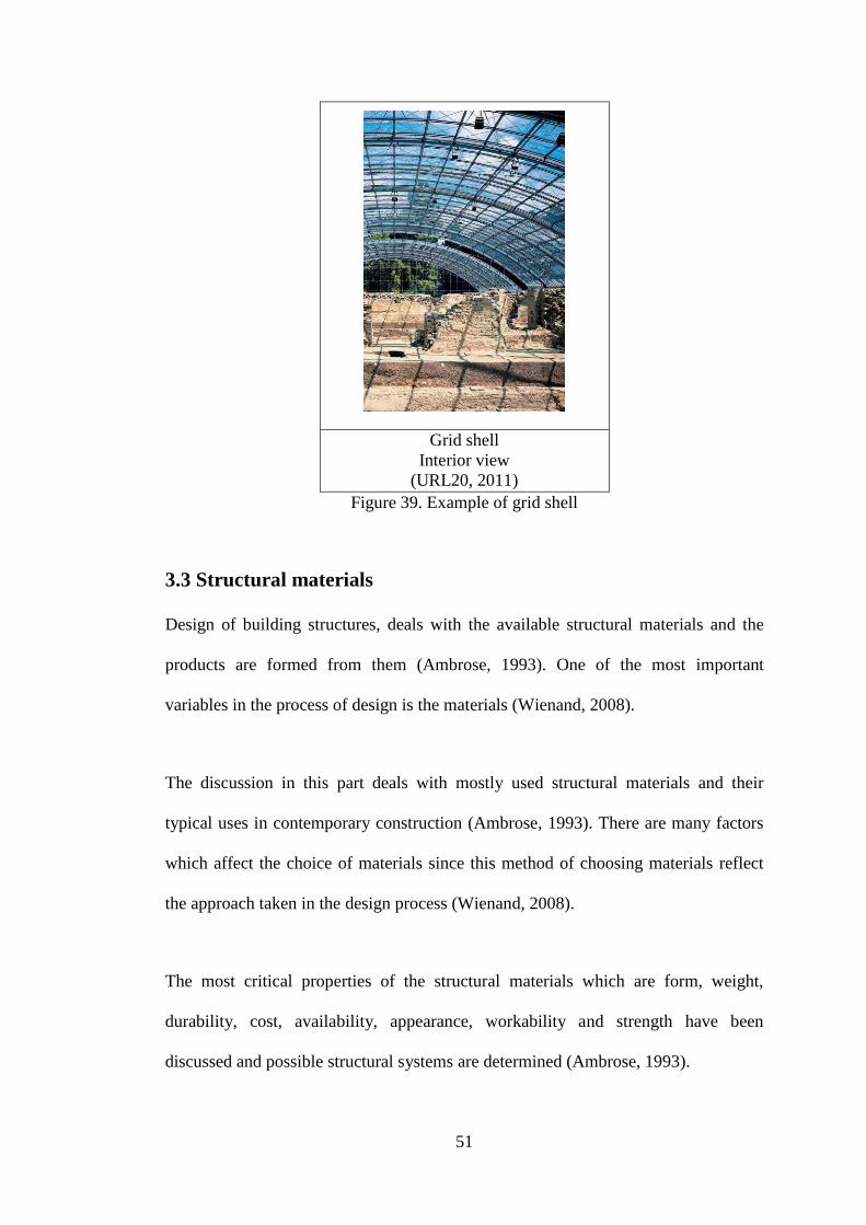
51
Grid shell
Interior view
(URL20, 2011)
Figure 39. Example of grid shell
3.3 Structural materials
Design of building structures, deals with the available structural materials and the
products are formed from them (Ambrose, 1993). One of the most important
variables in the process of design is the materials (Wienand, 2008).
The discussion in this part deals with mostly used structural materials and their
typical uses in contemporary construction (Ambrose, 1993). There are many factors
which affect the choice of materials since this method of choosing materials reflect
the approach taken in the design process (Wienand, 2008).
The most critical properties of the structural materials which are form, weight,
durability, cost, availability, appearance, workability and strength have been
discussed and possible structural systems are determined (Ambrose, 1993).

52
3.3.1 Stone
Stone is one of the earliest structural materials usually available at any locality with
various types, in association with mud or timber. It is much the most durable of the
four and therefore tended to be preferred because of its availability. It can be cut to
any shape when it is not possible simply to select usable blocks. Although it varies
greatly in hardness and internal structure (Mainstone, 1998), natural stones are
extremely durable (Everett, 1994). Stone is used in masonry structures.
Notre Dame Cathedral in Paris
(Photo: Author)
Figure 40. Example of stone building
3.3.2 Timber
From earliest times, timber has been used as a structural material. It affects both
tensile and compressive strength in the structural role. It is suitable for elements
which carry axial compression, axial tension and bending type internal forces
(Macdonald, 1994). Timber elements are light in weight when compared with stone;
additionally have high strength both in tension and compression (Everett, 1994).
Timber is mostly used in buildings of domestic scale as structural frameworks and
floors and roofs in load bearing masonry structures. Various elements such as rafters,

53
floor beams, skeleton frames, trusses, built up beams of various kinds, arches, shells
and folded forms is constructed with timber. Timber used in load bearing wall
structures both as the horizontal elements in masonry buildings and as vertical timber
elements which form wall panels (Macdonald, 1994).
Some of the longstanding limitation of timber has been overcome by technological
innovations hence size and form limitations have been expanded through glue
lamination and special techniques have made large structures possible through better
joint (Ambrose, 1993). Local availability and cost are major factors in the selection
of a timber as structural material. Because of its availability, low cost and simple
working possibilities, it is generally used as structural material of choice unless its
limitation (Ambrose, 1993).
Bodegas Protos Winery in Spain
by Richard Rogers
(URL17, 2011)
Figure 41. Example of timber
3.3.3 Reinforced Concrete
Concrete is a composite of stone fragments and cement binder which is made by
mixing together dry cement and aggregate in suitable proportions and adding water.
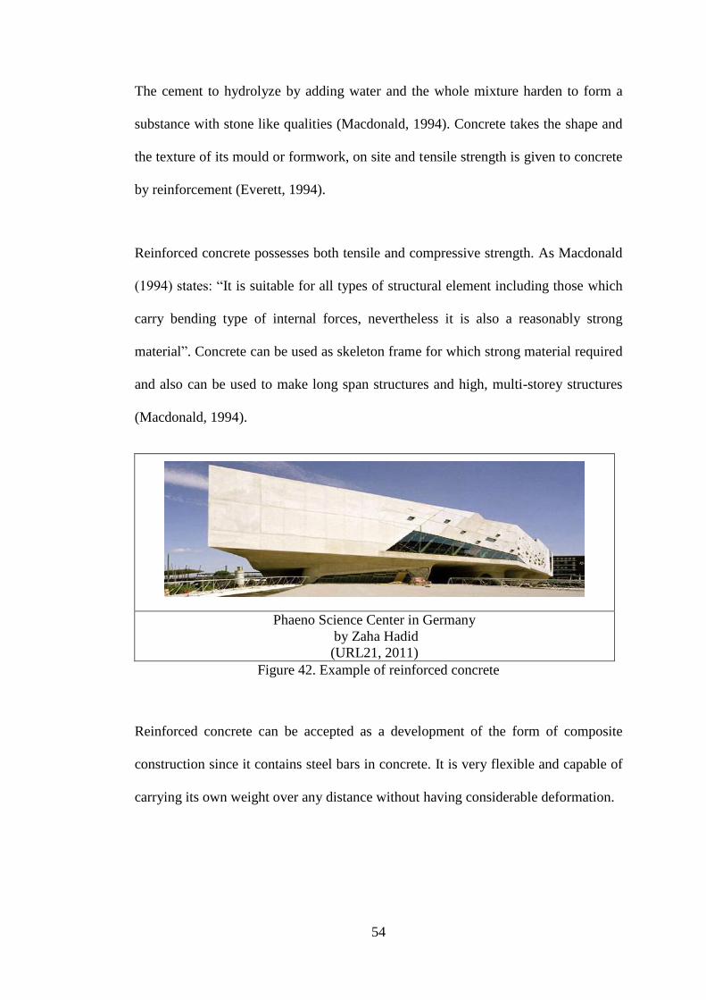
54
The cement to hydrolyze by adding water and the whole mixture harden to form a
substance with stone like qualities (Macdonald, 1994). Concrete takes the shape and
the texture of its mould or formwork, on site and tensile strength is given to concrete
by reinforcement (Everett, 1994).
Reinforced concrete possesses both tensile and compressive strength. As Macdonald
(1994) states: “It is suitable for all types of structural element including those which
carry bending type of internal forces, nevertheless it is also a reasonably strong
material”. Concrete can be used as skeleton frame for which strong material required
and also can be used to make long span structures and high, multi-storey structures
(Macdonald, 1994).
Phaeno Science Center in Germany
by Zaha Hadid
(URL21, 2011)
Figure 42. Example of reinforced concrete
Reinforced concrete can be accepted as a development of the form of composite
construction since it contains steel bars in concrete. It is very flexible and capable of
carrying its own weight over any distance without having considerable deformation.

55
Substantial formwork is required to give shape to the concrete until the concrete has
hardened enough to carry loads. The need to provide this formwork is, the main
limitation on the forms that can be economically adopted (Ambrose, 1993).
The PFA Building in USA
by Tadoo Ando
(URL21, 2011)
Figure 43. Example of reinforced concrete
3.3.4 Steel
The use of iron as a structural material has started from the late nineteenth century
when cheap methods for manufacturing it on a large scale were developed. Then
steel has been developed and it has been started to use in a variety of forms in nearly
every type of building. It is a material that has advantages as structural material. It
has high strength, equal strength in tension and compression and is suitable for the
every kind of structural elements (Macdonald, 1994). From huge columns to the
smallest nails, steel is the most adaptable structural material. It is also strongest and
the most resistant to aging (Ambrose, 1993). Its density is high but the ratio of
strength to weight is also high so that steel components are not heavy in relation to
their load carrying capacity (Macdonald, 1994).

56
Lyon Train Station
by Santiago Calatrava
(URL22, 2011)
Figure 44. Example of steel structure
Steel is a completely industrialized and fabricated material. Although the bulk
material is expensive its forming process is making it competitive with materials of
lower bulk cost since economy can also be achieved through mass production of
standardized items. The vocabulary of steel for building structures has recently been
expanded and there is now a wide range of use in different forms (Ambrose, 1993).
Law Faculty of Cambridge in England
Exterior view
(URL23, 2011)
Law Faculty of Cambridge
Facede Detail
(URL23, 2011)
Figure 45. Example of steel

57
3.4 Relationship between structure and material
Different types of structure systems and materials have been identified, their
differences and similarities have been determined above to be able to analyze the
structure system of the extensions and discuss the suitability of them in the analysis
chapter. Properties of the materials have been summed up in Table 3 and possible
structural systems have been determined with the related structural material in order
to see the relationship between structure systems and materials.

58
Table 3. Relationship between structure and material
STRUCTURAL
MATERIAL
PROPERTIES POSSIBLE
STRUCTURE
STONE Most durable
Availability problem
Heavy in weight
Strong in compression
Needs good craftsmanship
Shrinkage of the mortar is a
problem
Thermal expansion cracking
Limited forms can be created
Long time for construction
Masonry wall
Arch
Vault
Dome
TIMBER Light in weight compared
with stones
Suitable for elements which
carry axial compression and
tension
High strength
Flexible
Simple working possibilities
Availability problem
Weak against fire
Frame
Truss
Arch
REINFORCED
CONCRETE Strong in bending
Possesses tensile as well as
compressive strength
Shrinkage problem
Needs formwork
Long time for construction
Frame
Arch
Dome
Shell
Folded plate
STEEL High strength
Strength in tension and
compression
Light
Versatile
Longlife
Fast
Weak against fire
Frame
Truss
Space frame
Geodesic
dome
Cable
Tent

59
Chapter 4
DESIGN APPROACH
The study examines extensions by focusing on structural systems and their relation
on design. Design approaches are collected under four headings as: design principles,
ordering principles, organization and circulation. Factors have been defined and their
possible effect of the extension to the existing building has been identified.
4.1 Design principles
Design principles can be classified as unity, harmony, contrast, dominance,
repetition, balance, scale and proportion in this study.
4.1.1 Unity
Unity is related to composition in design which is produced by the relationship
between the visual elements. Building materials such as brick, timber and concrete
also provide the visual elements which form the composition. There are different
aspects of unity that must be satisfied in order to produce a satisfactory composition
(Smithies, 1981).
Different materials used in the remodeled buildings like stone, glass or steel create
variety of colors, tones and texture and can be accepted as elements of composition.
These are inherent aspects of most building materials. Old and new parts should be
contrasting but at the same time they should have unity. Unity can be achieved with
the following approaches:

60
Continuity of layout
Arrangement on series of axes
Harmonious layout with the existing building
Repetition of geometrical shapes
Balance throughout composition
Adding a little variety for proving a sense of personality
Appearance of completeness (Şahin, 2010); (URL 40)
Tate Modern London
Exterior view
(Brooker and Stone, 2007)
Tate Modern London
3D Model
(Brooker and Stone, 2007)
Figure 46. Unity between old and new by repetition of similar geometrical shapes
Similar geometric shapes are repeated with different sizes to achieve unity between
old and new in the extensions.
4.1.2 Harmony
Harmony is one of the aspects of unity. It may be concerned as opposite of contrast.
Harmony in color means, colors being related by being near to each other in the color
wheel. On the other hand, harmony in texture means a matching in the textural
quality (Smithies, 1981).

61
In remodeled buildings it refers the harmony of old and new. Although the old and
new parts should be differentiated, they should be in harmony as well to achieve
unity. Harmony can be achieved by following approaches:
Similarities of elements in terms of form or shape
Repetition of character with a little variety
Repetition of character providing right mix (Şahin, 2010); (URL40)
House Extension in Remscheid
(Schittich, 2003)
Figure 47. Repetition of character with a little variety to achieve harmony
Same unit is repeated with use of different materials to achieve harmony between
new and old.
4.1.3 Dominance
Dominance may be provided by the effect of one color, texture or element being
visually stronger than the reminder. A dominant form or shape can help to provide a
sense of unity. Dominance is one of the aspects of the unity. Unity can not exist if
there is a competition of visually equal elements. A dominance of old or new is
necessary to avoid an equal competition which would tent to destroy unity (Smithies,
1981).

62
Dominancy is used to break static organization of historic buildings and brings
dynamism to the structure by applying following approaches:
Creating center of interest
A sudden change in direction, size and shape. (Şahin, 2010) ; (URL40)
Cultural and Business Centre in Turin
(Schittich, 2003)
Figure 48. Creating center of interest to achieve dominancy
4.1.4 Contrast
Contrast of color, tone or texture, of direction or proportion, between solid and void,
give interest and vitality to a design. Harmony taken too far can lead to monotony, so
contrast is used to break this monotony. But too many contrasting elements will
weaken harmony and tend to produce more than one equal interest. This reduces any
dominance and weakens unity. The use of too many different elements leads to
visual chaos (Smithies, 1981). In order to achieve contrast, following approaches can
be applied. Contrast:
In terms of size
In terms of shape
In terms of direction
In terms of alignment

63
In terms of position (Şahin, 2010) ; (URL40)
Workshop building
in Rotterdam
(Schittich, 2003)
Figure 49. Contrast of shape and color
4.1.5 Repetition
Repetition of forms and shapes can be used to produce rhythm. On the other hand,
any repetition taken too far without change will eventually tend to monotony and will
destroy unity. Rhythm is a particularly useful way of providing harmony (Smithies,
1981). There are types of rhythm which will be discussed in the ordering principles
part.
ARM Storey Hall
in Melbourne
Maggie (1997)
Interior view
Maggie (1997)
Section
Maggie (1997)
Figure 50. Repetition of forms to achieve unity

64
4.1.6 Balance
Balance is one of the aspects of unity. Nevertheless, a design can be lacking balance
even though other aspects have been satisfied. It must be considered that when
balancing the design, symmetry must be avoided not to create monotony (Smithies,
1981). While combining old and new whole composition must be balanced. There
are two types of balance:
Informal balance in composition of layout
Formal balance in composition of layout (Şahin, 2010) ; (URL40)
Canova Museum in Italy by Carlo Scarpa
Interior view
(Brooker and Stone, 2007)
Canova Museum in Italy
Plan
(Brooker and Stone, 2007)
Figure 51. Addition is creating informal balance
New addition is creating informal balance in composition of layout. Old and new
part is not symmetrical but in balanced.
4.1.7 Proportion- Scale
In architecture, proportion is the geometric relationship of the volumes, also the ratio
or comparison of different parts of the composition. Proportional relationship is not
measured by eye, it can be compared and tend to judge the relationship of one part to
another on a proportional basis. Proportional relationship of the historical buildings
was more successful; however proportion is less emphasized on simpler forms of
modern buildings (Smithies, 1981).

65
While remodeling old buildings existing proportional relationship should not be
destroyed and it should be taken into consideration that additional part should not
over dominate the existing building in terms of scale as shown in the figure.
Extension in correct scale and proportions
(Douglas, 2006)
Extension over dominating existing
(Douglas, 2006)
Figure 52. Relationship between existing and extension in terms of scale and
proportion
Various approaches to achieve proportion and scale in design are:
Achieving human scale
Height to width ratio
Proportion between existing space and addition (Şahin, 2010); (URL40)
Antwerp Central Port Building in Belgium
By Zaha Hadid
(URL24, 2011)
Figure 53. Addition over dominating the existing building

66
4.2 Ordering Principles
Ordering principles are axis, symmetry, hierarchy, datum, rhythm and
transformation.
4.2.1 Axis
Axis is a line between two points which orders forms and spaces around it
symmetrically or in balance. It is the basic tool in ordering forms and spaces in
architecture. Although it is invisible, it is a strong and dominant line. It gives a
symmetrical effect but still it is in balance. Characters of the elements around the
axis, define visual strength of the organization (Ching, 2002).
Axis is a linear element and it obtains movement and view along the route. To be
well defined, it should have a starting and ending point, additionally its edges can be
defined with planes or spaces around it. According to the Ching (2002) there are four
types of axis according to the starting and ending points as:
Points in space established by vertical and linear elements or centralized
building forms (Figure 54a)
Vertical planes, such as symmetrical building facades or fronts, preceded by a
forecourt or similar open space (Figure 54b)
Well-defined spaces, generally centralized or regular in form (Figure 54c)
Gateways that open outward toward a view or vista beyond (Figure 54d)

67
a
b
c
d
(Ching, 2002)
Figure 54. Types of axis
4.2.2 Symmetry
Symmetry is a concept of order which arises from a reflected disposition of elements
on one side and on the other side of the axis, as in a mirror. It is a special case of the
principle unity through orientation of elements. A symmetrical organization acts as a
magnet in comparison with the asymmetrical although it provokes monotony
(Meiss, 1990).
Basically there are two types of symmetry:
Bilateral: It describes symmetry which equal elements are organized around
an axis.
Central: It is composed of elements which intersect on a central point,
balanced with an axis

68
Baltic Art Factory
Exterior view
(Brooker and Stone, 2007)
Baltic Art Factory
3D Model
(Brooker and Stone, 2007)
Figure 55. Example of bilateral symmetry
4.2.3 Hierarchy
Hierarchy is a more complex order in comparison to the symmetry since similarity
between elements is not necessary (Meiss, 1990). Hierarchy principle expresses
differences between forms or spaces. These differences show the levels of the
importance between elements in an organization. A form or shape must be unique in
order to be distinctive in an organization. Uniqueness can be achieved in three ways:
By exceptional size
By a unique shape
By strategic location
In an architectural composition, a form or space can be different from other elements
by an exceptional size and become dominant element of the organization. The other
way to achieve hierarchy is to change the shape of one element in order to create
contrast between elements. Thirdly, an important element in the design can be placed
in a strategic location to create hierarchy between elements (Ching, 2002).

69
ING and NNH Bank, Exterior view
(Powell, 1999)
ING and NNH Bank, Section
(Powell, 1999)
Figure 56. Hierarchy by a unique shape
4.2.4. Datum
Datum expresses a line, plane or a volume that creates relationship between elements
in a composition. It creates its own way to make connections between different
elements. It has similarities between axis that discussed in previous part but a datum
does not have to be a linear element, it can be planar or volumetric.
Point, Line, Plane and Volume
(Ching, 2004)
Figure 57. Types of datum

70
According to Ching (2002), datum can organize randomly selected elements that do
not have similarities in three ways:
Line
Plane
Volume
A single line may divide a group of object into parts or a group of lines may from a
grid to provide an organization (Ching, 2002).
A plane may collect elements under it or may form a background to frame the
elements (Ching, 2002). Planes organize and separate spaces. A plane, whether it is
horizontal or vertical, is a major element of design control, used both inside and
outside a building and is probably the most obvious and easily recognizable detailed
element in any building (Brooker and Stone, 2004).
An additional plane in a remodeled building can be additional mezzanine floor
inserted inside of the existing building, a wrapping plane that collects different parts
together or an attached plane on an existing building which defines closed spaces as
roofs.

71
National Studio for
Contemporary Arts
(Brooker and Stone, 2004)
Figure 58. Example of wrapping plane
A volume may group different elements into its border, may order elements around
its frame (Ching, 2002) or it can be inserted into the building to create unity and
order between elements formally for a different function.
An object is loaded with meaning establishes a physical and cultural relationship
with its environment. It can be a large sculpture or a number of elements clustered
together and can effect the perception of the space or it can form a focal point or
even a landmark (Brooker and Stone, 2004).
4.2.5 Rhythm
Repetition of forms, shapes or lines in a systematic and harmonic way is called
rhythm. It is used in different disciplines like music as well as design. This idea is
placed in architecture as repetition of forms and spaces with an order. Nearly all
types of buildings have this principle with repetition of different building elements
like, structural elements, openings or space modules. Elements that will be repeated
do not have to be exactly same but these elements should be grouped according to:

72
Size
Shape
Detail characteristic (Ching, 2002).
La Llauna School in Barcelona
Interior view
(Brooker and Stone, 2007)
La Llauna School in Barcelona
Plan
(Brooker and Stone, 2007)
Figure 59. Example of Rhythm
4.2.6 Transformation
Transformation principle is to take an architectural model as a prototype and
organize a new design by having references with the prototype. These references can
be its form, order of elements or material characteristics (Ching, 2002).
Reichstag Parliament House in Berlin
(Powell, 1999)
Figure 60. Transformation of dome into contemporary architecture
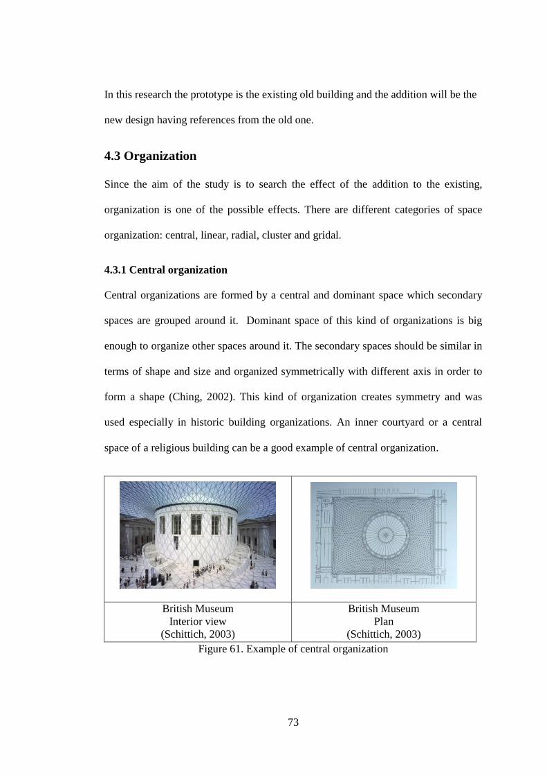
73
In this research the prototype is the existing old building and the addition will be the
new design having references from the old one.
4.3 Organization
Since the aim of the study is to search the effect of the addition to the existing,
organization is one of the possible effects. There are different categories of space
organization: central, linear, radial, cluster and gridal.
4.3.1 Central organization
Central organizations are formed by a central and dominant space which secondary
spaces are grouped around it. Dominant space of this kind of organizations is big
enough to organize other spaces around it. The secondary spaces should be similar in
terms of shape and size and organized symmetrically with different axis in order to
form a shape (Ching, 2002). This kind of organization creates symmetry and was
used especially in historic building organizations. An inner courtyard or a central
space of a religious building can be a good example of central organization.
British Museum
Interior view
(Schittich, 2003)
British Museum
Plan
(Schittich, 2003)
Figure 61. Example of central organization

74
4.3.2 Linear organization
Linear organizations are formed by repeated spaces on a line which have similarities
in terms of size, shape and function. Because of its length linear organizations define
a movement and a growth so they always need an end point as dominant spaces or
shapes (Ching, 2002).
Interior view
Section
Documentation Center
(Brooker and Stone, 2008)
Figure 62. Example of linear organization
4.3.3 Radial organization
Radial organizations consist of linear space organizations, starting from a central
point. It combines center and the linear elements each other. The arms coming from
the central point should be similar in terms of form and size. It has similarities with
the central organizations. Central organizations create an introverted organization
that focuses one point. On the other hand, radial organizations create extroverted
organizations which are open to the outside (Ching, 2002).
Zumtobel Staff Showroom
Interior view
(Brooker and Stone, 2004)
Zumtobel Staff Showroom
3D Model
(Brooker and Stone, 2004)
Figure 63. Example of radial organization
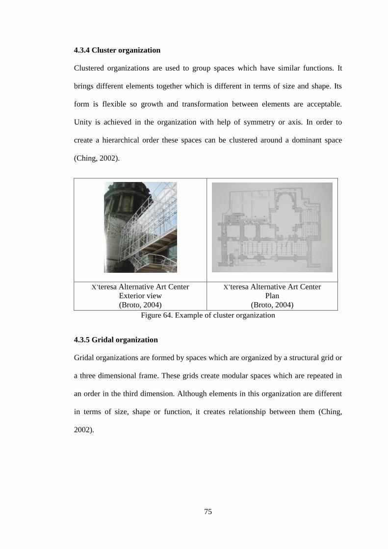
75
4.3.4 Cluster organization
Clustered organizations are used to group spaces which have similar functions. It
brings different elements together which is different in terms of size and shape. Its
form is flexible so growth and transformation between elements are acceptable.
Unity is achieved in the organization with help of symmetry or axis. In order to
create a hierarchical order these spaces can be clustered around a dominant space
(Ching, 2002).
X’teresa Alternative Art Center
Exterior view
(Broto, 2004)
X’teresa Alternative Art Center
Plan
(Broto, 2004)
Figure 64. Example of cluster organization
4.3.5 Gridal organization
Gridal organizations are formed by spaces which are organized by a structural grid or
a three dimensional frame. These grids create modular spaces which are repeated in
an order in the third dimension. Although elements in this organization are different
in terms of size, shape or function, it creates relationship between them (Ching,
2002).
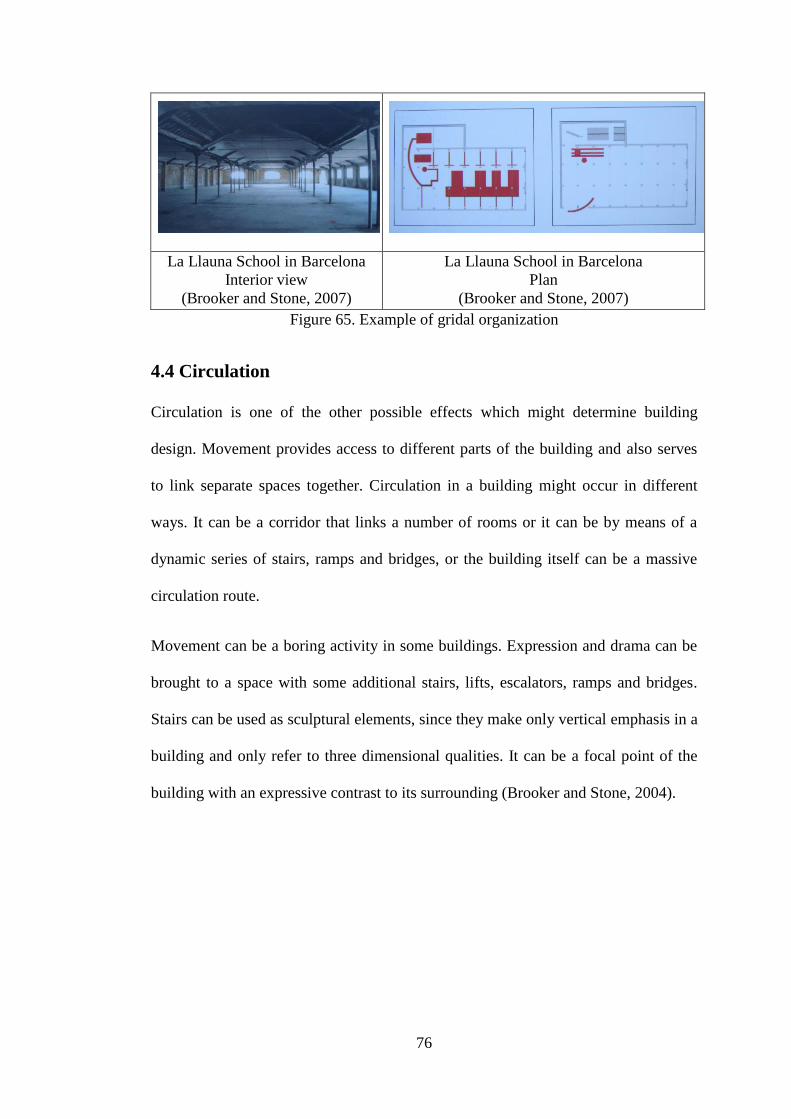
76
La Llauna School in Barcelona
Interior view
(Brooker and Stone, 2007)
La Llauna School in Barcelona
Plan
(Brooker and Stone, 2007)
Figure 65. Example of gridal organization
4.4 Circulation
Circulation is one of the other possible effects which might determine building
design. Movement provides access to different parts of the building and also serves
to link separate spaces together. Circulation in a building might occur in different
ways. It can be a corridor that links a number of rooms or it can be by means of a
dynamic series of stairs, ramps and bridges, or the building itself can be a massive
circulation route.
Movement can be a boring activity in some buildings. Expression and drama can be
brought to a space with some additional stairs, lifts, escalators, ramps and bridges.
Stairs can be used as sculptural elements, since they make only vertical emphasis in a
building and only refer to three dimensional qualities. It can be a focal point of the
building with an expressive contrast to its surrounding (Brooker and Stone, 2004).

77
Kadir Has University
inner courtyard
Photo: Author
Figure 66. Circulation elements can be used as sculptural elements
Circulation which can be analyzed under three headings as:
Configuration of the path
Path- space relationship
Type of the circulation element (Ching, 2002)
Configuration of the path can be divided as: linear, radial, spiral, grid, network or
composite (Ching, 2002).
Path- space relationship shows the relationship between existing space and the
additional circulation element. It can be divided as: pass by spaces, pass through
spaces and terminate in a space (Ching, 2002).

78
Pass by spaces (Ching, 2002)
Pass through spaces (Ching, 2002)
Terminate in a space (Ching, 2002)
Figure 67. Path-space relationship
Type of circulation element indicated if it is a stair, escalator, ramp or bridge.
Circulation elements are not just used to provide movement in the building. They can
be used as design elements according to the function of the building. Existing floors
of the old building have been removed and a circular ramp is inserted in the middle
of the building providing circulation up to last floor of the building (Figure 68).

79
Museo del Novecento
Exterior view
(Photo: Cemal
Osmanlılar)
Museo del Novecento
Interior view
(Photo: Cemal
Osmanlılar)
Museo del Novecento
Façade detail
(Photo: Cemal
Osmanlılar)
Figure 68. Ramp addition into an old building as a circulation element
Factors effecting design have been defined and their possible approach identified in
this chapter. In the following chapter, selected case studies have been analyzed
according to the identified criteria.
80
Chapter 5
CASE STUDIES
5.1 Selection of the case studies
20 case studies of remodeled buildings are selected according to the following
properties:
Selected buildings are public buildings which are converted into different
functions like museums, cultural centers, libraries, etc.
Existing structures are masonry and the proposed additions have
contemporary structure.
There are historic buildings as well as ordinary old buildings; however the
historic buildings are the ones that designers are free about the limit of
interventions.
5.2 Method of analysis
A series of tables were developed in order to analyze the case studies. In the first
table general information has been given about the case studies as well as photos and
drawings of the building. Required photos and drawings have been selected in order
to perceive the buildings. On the table, type of the related extension is identified
which have been grouped into five categories as integrated, inserted, attached,
wrapped and pierced. These categories are introduced after the analysis of the case
studies which were selected out of 100 examples.

81
The second table consists of two parts: in the first part, buildings have been analyzed
in terms of design approaches. The criteria of the design approach are design
principles, ordering principles, organization and circulation. Selected buildings have
been analyzed according to these criteria in order to find the answers of “what the
effect of the addition to the existing is; and what their relationship is”. Factors that
are satisfied have been marked on the matrix. Unity, harmony, contrast, dominance,
balance, repetition, scale or proportions are the factors of design principles. Axis,
rhythm, datum, hierarchy and transformation are the factors of order.
In the third table, buildings have been analyzed in terms of their structural approach.
The criteria of the structural approach are structure system, material and the
connection between old and new: which structure system is used for the addition,
what is the structural material and how the proposed addition is connected with the
existing building. At the end of this analysis a method has been developed to
evaluate the case studies.

82
5.3 Analysis of the case studies
Table 4. General Information about Documentation center
CASE STUDY 1 NAME OF THE BUILDING: DOCUMENTATION CENTER FOR THE THIRD REICH
LOCATION: NUREMBERG, GERMANY
EXISTING ADDITION
CONSTRUCTION DATE :1930S CONSTRUCTION DATE :2002
OLD FUNCTION: MEETING PLACE NEW FUNCTION: DOCUMENTATION
CENTER
CENTER
ARCHITECT : ALPERT SPEER ARCHITECT :GUNTHER DOMENIG
STRUCTURE SYSTEM: MASONRY STRUCTURE SYSTEM: FRAME
MATERIAL: BRICK MATERIAL: STEEL
EXTERIOR VIEW (Brooker and Stone, 2007) INTERIOR VIEW (Broto, 2004)
SCHEMATIC PLAN (Brooker and Stone, 2007)
2007)
SCHEMATIC SECTION (Brooker and Stone, 2007)
SECTION (Brooker and Stone, 2007)
ELEVATION (Brooker and Stone, 2007) INTEGRATED INSERTED ATTACHED WRAPPED PIERCED
X

83
Table 5. Analysis of the Documentation Center
CASE STUDY 1: DOCUMENTATION CENTER FOR THE THIRD REICH
POSSIBLE EFFECT OF THE ADDITIONAL PART TO THE DESIGN APPROACH
FACTORS APPROACH D
ES
IGN
PR
INC
IPL
ES
UNITY Continuity of layout
Arrangement on series of axes
Harmonious layout with existing old
building
Repetition of geometrical shapes
Balance throughout composition X
Adding a little variety for proving a sense
of personality
X
Appearance of completeness
HARMONY Similarities of elements in terms of shape
Repetition of character with a little
variety
Repetition of character providing right
mix
DOMINANCE Creating center of interest X
A sudden change in direction X
A sudden change in size
A sudden change in shape X
CONTRAST In terms of size
In terms of shape X
In terms of direction X
In terms of alignment
In terms of position X
REPETITION Repetition of existing layout
BALANCE Informal balance in composition of
layout
X
Formal balance in composition of layout
SCALE
PROPORTITION
Achieving human scale
Appropriate height to width ratio X
Proportion between existing space and
addition
X
OR
DE
RIN
G P
RIN
CIP
LE
S AXIS Points in space established by vertical,
linear elements or centralized building
forms
Vertical planes, such as symmetrical
building facades, preceded by a forecourt
or similar open space
Well-defined spaces, centralized or
regular in form
X

84
Gateways that open outward toward a
view or vista beyond
SYMMETRY Bilateral
Radial
HIERARCHY By exceptional size
By a unique shape X
By strategic location X
DATUM Line
Plane
Volume X
RHYTHM Size
Shape
Detail characteristic
TRANSFORMATION Using existing as prototype
CIR
CU
LA
TIO
N
CONFIGURATION
OF THE PATH
Linear X
Radial
Spiral
Grid
Network
Composite
PATH-SPACE
RELATIONSHIP
Pass by spaces
Pass through spaces X
Terminate in a space X
TYPE OF THE
CIRCULATION
ELEMENT
Stair- escalator X
Ramp
Bridge
OR
GA
NIZ
AT
ION
TYPE OF
ORGANIZATION
OLD NEW
CENTRAL X CENTRAL
LINEAR LINEAR X
RADIAL RADIAL
CLUSTER CLUSTER
GRIDAL GRIDAL
Adapted from
(Şahin, 2010); (URL40)
(Ching, 2002)
(Brooker and Stone, 2004)

85
STRUCTURAL APPROACH
ST
RU
CT
UR
E S
YS
TE
M
FORM ACTIVE VECTOR ACTIVE SECTION ACTIVE SURFACE
ACTIVE Frame:
-Steel frames are
used as the
structural system of
the circulation
route.
-It is a light
material and it is
easy to construct in
the existing
masonry buildings.
MA
TE
RIA
L
STEEL TIMBER R.C. STONE
-Steel is used as
structural material
and it is covered
with glass.
-A contrast is
created with the use
of steel and glass in
the brick masonry
building.
CO
NN
EC
TIO
N
SUSPENDED
FROM EXISTING
STRUCTURE
ATTACHED FREESTANDING COMPLEX
-Circulation bridge
is piercing the
existing building
with a slope.
-The addition is
suspended over the
stone columns at
the points where
the bridge is in the
building.

86
Table 6. General Information about Tate Modern
CASE STUDY 2 NAME OF THE BUILDING: TATE MODERN
LOCATION: LONDON, UK
EXISTING ADDITION
CONSTRUCTION DATE : 1947-1963 CONSTRUCTION DATE : 2000
OLD FUNCTION: POWER STATION NEW FUNCTION: ART GALLERY
CENTER
ARCHITECT : GILES GILBERT SCOTT ARCHITECT: HERZOG &DE MEURON
STRUCTURE SYSTEM: MASONRY STRUCTURE SYSTEM: TRUSS
MATERIAL: BRICK MATERIAL: STEEL
EXTERIOR VIEW (Schittich, 2003) INTERIOR VIEW (Broto, 2004)
3D MODEL (Brooker and Stone, 2007) PLAN (Powell, 1999)
SECTION (Powell, 1999) ELEVATION (Powell, 1999)
INTEGRATED INSERTED ATTACHED WRAPPED PIERCED
X

87
Table 7. Analysis of Tate Modern
CASE STUDY 2: TATE MODERN POSSIBLE EFFECT OF THE ADDITIONAL PART TO THE DESIGN APPROACH
FACTORS APPROACH D
ES
IGN
PR
INC
IPL
ES
UNITY Continuity of layout X
Arrangement on series of axes X
Harmonious layout with existing old
building
X
Repetition of geometrical shapes X
Balance throughout composition X
Adding a little variety for proving a sense
of personality
Appearance of completeness
HARMONY Similarities of elements in terms of shape X
Repetition of character with a little
variety
Repetition of character providing right
mix
DOMINANCE Creating center of interest X
A sudden change in direction
A sudden change in size
A sudden change in shape
CONTRAST In terms of size
In terms of shape
In terms of direction
In terms of alignment
In terms of position
REPETITION Repetition of existing layout X
BALANCE Informal balance in composition of
layout
Formal balance in composition of layout X
SCALE
PROPORTITION
Achieving human scale X
Appropriate height to width ratio X
Proportion between existing space and
addition
X
OR
DE
RIN
G P
RIN
CIP
LE
S AXIS
Points in space established by vertical,
linear elements or centralized building
forms
Vertical planes, such as symmetrical
building facades, preceded by a forecourt
or similar open space
Well-defined spaces, centralized or
regular in form

88
Gateways that open outward toward a
view or vista beyond
SYMMETRY Bilateral X
Radial
HIERARCHY By exceptional size
By a unique shape
By strategic location
DATUM Line
Plane
Volume X
RHYTHM Size
Shape
Detail characteristic
TRANSFORMATION Using existing as prototype X
CIR
CU
LA
TIO
N
CONFIGURATION
OF THE PATH
Linear X
Radial
Spiral
Grid
Network
Composite
PATH-SPACE
RELATIONSHIP
Pass by spaces X
Pass through spaces
Terminate in a space
TYPE OF THE
CIRCULATION
ELEMENT
Stair- escalator X
Ramp
Bridge
OR
GA
NIZ
AT
ION
TYPE OF
ORGANIZATION
OLD NEW
CENTRAL CENTRAL
LINEAR X LINEAR X
RADIAL RADIAL
CLUSTER CLUSTER
GRIDAL GRIDAL
Adapted from
(Şahin, 2010) ; (URL40)
(Ching, 2002)
(Brooker and Stone, 2004)

89
STRUCTURAL APPROACH
ST
RU
CT
UR
E S
YS
TE
M
FORM ACTIVE VECTOR ACTIVE SECTION ACTIVE SURFACE
ACTIVE Truss:
Truss is used as the
structural system of
the roof and it is
supported with
steel columns. It is
a light material and
it is easy to
construct in the
existing masonry
buildings.
MA
TE
RIA
L
STEEL TIMBER R.C. STONE
Steel is used as
structural material
and it is covered
with glass. A
contrast is created
with the use of steel
and glass in the
brick masonry
building.
CO
NN
EC
TIO
N
SUSPENDED
FROM EXISTING
STRUCTURE
ATTACHED FREESTANDING COMPLEX
Additional volume
is a freestanding
element which is
not touching to the
existing walls.
Truss roof is
supported with
steel columns
located at the edge
of the existing
walls.

90
Table 8. Analysis of Archbishopric Museum
CASE STUDY 3 NAME OF THE BUILDING: ARCHBISHOPRIC MUSEUM
LOCATION: HAMAR, NORWAY
EXISTING ADDITION
CONSTRUCTION DATE : UNKNOWN CONSTRUCTION DATE : 1967-1979
OLD FUNCTION: BARN NEW FUNCTION: MUSEUM
CENTER
ARCHITECT : UNKNOWN ARCHITECT: SVERRE FEHN
STRUCTURE SYSTEM: MASONRY STRUCTURE SYSTEM: FRAME
MATERIAL: BRICK MATERIAL: REINFORCED CONCRETE
VIEW FROM COURTYARD (URL25, 2011) INTERIOR VIEW (Brooker and Stone, 2007)
3D MODEL (Brooker and Stone, 2007) EXTERIOR VIEW (URL1, 2011)
SITE PLAN (URL25, 2011) PLAN (URL25, 2011)
INTEGRATED INSERTED ATTACHED WRAPPED PIERCED
X

91
Table 9. Analysis of Archbishopric Museum
CASE STUDY 3: ARCHBISHOPRIC MUSEUM POSSIBLE EFFECT OF THE ADDITIONAL PART TO THE DESIGN APPROACH
FACTORS APPROACH D
ES
IGN
PR
INC
IPL
ES
UNITY Continuity of layout
Arrangement on series of axes
Harmonious layout with existing old
building
Repetition of geometrical shapes
Balance throughout composition X
Adding a little variety for proving a
sense of personality
X
Appearance of completeness
HARMONY Similarities of elements in terms of
shape
Repetition of character with a little
variety
Repetition of character providing right
mix
DOMINANCE Creating center of interest X
A sudden change in direction X
A sudden change in size X
A sudden change in shape X
CONTRAST In terms of size X
In terms of shape X
In terms of direction X
In terms of alignment
In terms of position X
REPETITION Repetition of existing layout
BALANCE Informal balance in composition of
layout
X
Formal balance in composition of
layout
SCALE
PROPORTITION
Achieving human scale X
Appropriate height to width ratio
Proportion between existing space and
addition
OR
DE
RIN
G P
RIN
CIP
LE
S AXIS Points in space established by vertical,
linear elements or centralized building
forms
Vertical planes, such as symmetrical
building facades, preceded by a
forecourt or similar open space
Well-defined spaces, centralized or
regular in form

92
Gateways that open outward toward a
view or vista beyond
X
SYMMETRY Bilateral
Radial
HIERARCHY By exceptional size
By a unique shape X
By strategic location X
DATUM Line
Plane
Volume X
RHYTHM Size
Shape
Detail characteristic
TRANSFORMATION Using existing as prototype
CIR
CU
LA
TIO
N
CONFIGURATION OF
THE PATH
Linear X
Radial
Spiral
Grid
Network
Composite
PATH-SPACE
RELATIONSHIP
Pass by spaces
Pass through spaces X
Terminate in a space X
TYPE OF THE
CIRCULATION
ELEMENT
Stair- escalator
Ramp
Bridge X
OR
GA
NIZ
AT
ION
TYPE OF
ORGANIZATION
OLD NEW
CENTRAL X CENTRAL
LINEAR LINEAR X
RADIAL RADIAL
CLUSTER CLUSTER
GRIDAL GRIDAL
Adapted from
(Sahin, 2010) ; (URL40)
(Ching, 2002)
(Brooker and Stone, 2004)

93
STRUCTURAL APPROACH
ST
RU
CT
UR
E S
YS
TE
M
FORM ACTIVE VECTOR ACTIVE SECTION ACTIVE SURFACE
ACTIVE Frame:
-Frames used as the
structural system of
the bridge which
provides circulation
in the museum.
-Columns are
sitting on the
ground and
supporting the
bridge.
MA
TE
RIA
L
STEEL TIMBER R.C. STONE
-R.C. is used as
structural material
since it is not a
frequently used
material in the
addition.
-Concrete has left
exposed to give a
dramatic effect in
the old building.
CO
NN
EC
TIO
N
SUSPENDED
FROM EXISTING
STRUCTURE
ATTACHED FREESTANDING COMPLEX
-Additional volume
is a freestanding
element which is
not touching to the
existing walls.
-The bridge which
is passing through
the existing
building is
supported with
reinforced concrete
columns.

94
Table 10. General information of Ing and Nnh Bank
CASE STUDY 4 NAME OF THE BUILDING: ING AND NNH BANK
LOCATION: BUDAPEST, HUNGARY
EXISTING ADDITION
CONSTRUCTION DATE : 1882 CONSTRUCTION DATE : 1992-1997
OLD FUNCTION: UNKNOWN NEW FUNCTION: OFFICE BUILDING
CENTER
ARCHITECT : UNKNOWN ARCHITECT: ERIC VAN EGERAAT
STRUCTURE SYSTEM: MASONRY STRUCTURE SYSTEM: ARCH
MATERIAL: BRICK MATERIAL: TIMBER
EXTERIOR VIEW (Powell, 1999) EXTERIOR VIEW (Powell, 1999)
ROOF (Brooker and Stone, 2007) INTERIOR VIEW (Brooker and Stone, 2007)
SECTION (Powell, 1999) PLAN (Powell, 1999)
INTEGRATED INSERTED ATTACHED WRAPPED PIERCED
X

95
Table 11. Analysis of Ing and Nnh Bank
CASE STUDY 4: ING AND NNH BANK
POSSIBLE EFFECT OF THE ADDITIONAL PART TO THE DESIGN APPROACH
FACTORS APPROACH D
ES
IGN
PR
INC
IPL
ES
UNITY Continuity of layout
Arrangement on series of axes
Harmonious layout with existing old
building
Repetition of geometrical shapes
Balance throughout composition
Adding a little variety for proving a
sense of personality
Appearance of completeness
HARMONY Similarities of elements in terms of
shape
Repetition of character with a little
variety
Repetition of character providing right
mix
DOMINANCE Creating center of interest X
A sudden change in direction
A sudden change in size X
A sudden change in shape X
CONTRAST In terms of size X
In terms of shape X
In terms of direction X
In terms of alignment
In terms of position
REPETITION Repetition of existing layout
BALANCE Informal balance in composition of
layout
Formal balance in composition of
layout
X
SCALE
PROPORTITION
Achieving human scale X
Height to width ratio
Proportion between existing space and
addition
X
OR
DE
RIN
G P
RIN
CIP
LE
S AXIS Points in space established by vertical,
linear elements or centralized building
forms
Vertical planes, such as symmetrical
building facades, preceded by a
forecourt or similar open space
Well-defined spaces, centralized or
regular in form

96
Gateways that open outward toward a
view or vista beyond
SYMMETRY Bilateral
Radial
HIERARCHY By exceptional size
By a unique shape X
By strategic location
DATUM Line
Plane
Volume
RHYTHM Size
Shape
Detail characteristic
TRANSFORMATION Using existing as prototype
CIR
CU
LA
TIO
N
CONFIGURATION
OF THE PATH
Linear
Radial
Spiral
Grid
Network
Composite
PATH-SPACE
RELATIONSHIP
Pass by spaces
Pass through spaces
Terminate in a space
TYPE OF THE
CIRCULATION
ELEMENT
Stair- escalator
Ramp
Bridge
OR
GA
NIZ
AT
ION
TYPE OF
ORGANIZATION
OLD NEW
CENTRAL CENTRAL
LINEAR LINEAR
RADIAL RADIAL
CLUSTER X CLUSTER X
GRIDAL GRIDAL
Adapted from
(Sahin, 2010) ; (URL40)
(Ching, 2002)
(Brooker and Stone, 2004)

97
STRUCTURAL APPROACH
ST
RU
CT
UR
E S
YS
TE
M FORM ACTIVE VECTOR
ACTIVE
SECTION
ACTIVE
SURFACE
ACTIVE Arch:
-Timber arches
were repeated
continuously and
formed a spherical
structure.
MA
TE
RIA
L
STEEL TIMBER R.C. STONE
-Timber is the
structural material
of the repeated
arches.
-Gaps between
arches are covered
with glass for
transparency.
CO
NN
EC
TIO
N
SUSPENDED
FROM EXISTING
STRUCTURE
ATTACHED FREESTANDING COMPLEX
- Additional
volume is at the top
of the building.
-It is attached to
the walls of the
existing
buildings.

98
Table 12. General information of the Reichstag
CASE STUDY 5 NAME OF THE BUILDING: THE REICHSTAG
LOCATION: BERLIN, GERMANY
EXISTING ADDITION
CONSTRUCTION DATE : 1894 CONSTRUCTION DATE : 1992-1999
OLD FUNCTION: PARLIAMENT HOUSE NEW FUNCTION: PARLIAMENT HOUSE
CENTER
ARCHITECT : PAUL WALLOT ARCHITECT: NORMAN FOSTER
STRUCTURE SYSTEM: MASONRY STRUCTURE SYSTEM: DOME
MATERIAL: BRICK MATERIAL: STEEL
EXTERIOR VIEW (Powell, 1999) CONSTRUCTION PROCESS (Powell, 1999)
3D SKETCH (Powell, 1999) SECTION (Powell, 1999)
INTEGRATED INSERTED ATTACHED WRAPPED PIERCED
X

99
Table 13. Analysis of the Reichstag
CASE STUDY 5: THE REICHSTAG POSSIBLE EFFECT OF THE ADDITIONAL PART TO THE DESIGN APPROACH
FACTORS APPROACH D
ES
IGN
PR
INC
IPL
ES
UNITY Continuity of layout
Arrangement on series of axes
Harmonious layout with existing old
building
Repetition of geometrical shapes
Balance throughout composition
Adding a little variety for proving a sense
of personality
Appearance of completeness
HARMONY Similarities of elements in terms of shape
Repetition of character with a little
variety
Repetition of character providing right
mix
DOMINANCE Creating center of interest X
A sudden change in direction
A sudden change in size
A sudden change in shape X
CONTRAST In terms of size X
In terms of shape X
In terms of direction
In terms of alignment X
In terms of position X
REPETITION Repetition of existing layout
BALANCE Informal balance in composition of
layout
X
Formal balance in composition of layout
SCALE
PROPORTITION
Achieving human scale
Appropriate height to width ratio X
Proportion between existing space and
addition
X
OR
DE
RIN
G P
RIN
CIP
LE
S
AXIS Points in space established by vertical,
linear elements or centralized building
forms
Vertical planes, such as symmetrical
building facades, preceded by a forecourt
or similar open space
Well-defined spaces, centralized or
regular in form

100
Gateways that open outward toward a
view or vista beyond
SYMMETRY Bilateral X
Radial
HIERARCHY By exceptional size
By a unique shape X
By strategic location X
DATUM Line
Plane
Volume
RHYTHM Size
Shape
Detail characteristic
TRANSFORMATION Using existing as prototype
CIR
CU
LA
TIO
N
CONFIGURATION
OF THE PATH
Linear
Radial
Spiral X
Grid
Network
Composite
PATH-SPACE
RELATIONSHIP
Pass by spaces
Pass through spaces
Terminate in a space X
TYPE OF THE
CIRCULATION
ELEMENT
Stair- escalator
Ramp X
Bridge
OR
GA
NIZ
AT
ION
TYPE OF
ORGANIZATION
OLD NEW
CENTRAL X CENTRAL X
LINEAR LINEAR
RADIAL RADIAL
CLUSTER CLUSTER
GRIDAL GRIDAL
Adapted from
(Şahin, 2010) ; (URL40)
(Ching, 2002)
(Brooker and Stone, 2004)
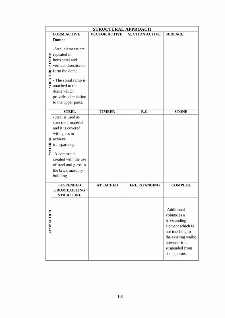
101
STRUCTURAL APPROACH
ST
RU
CT
UR
E S
YS
TE
M
FORM ACTIVE VECTOR ACTIVE SECTION ACTIVE SURFACE
ACTIVE Dome:
-Steel elements are
repeated in
horizontal and
vertical direction to
form the dome.
- The spiral ramp is
attached to the
dome which
provides circulation
to the upper parts.
MA
TE
RIA
L
STEEL TIMBER R.C. STONE
-Steel is used as
structural material
and it is covered
with glass to
achieve
transparency.
-A contrast is
created with the use
of steel and glass in
the brick masonry
building.
CO
NN
EC
TIO
N
SUSPENDED
FROM EXISTING
STRUCTURE
ATTACHED FREESTANDING COMPLEX
-Additional
volume is a
freestanding
element which is
not touching to
the existing walls;
however it is
suspended from
some points.

102
Table 14. General information of the British Museum
CASE STUDY 6 NAME OF THE BUILDING: GREAT COURT , BRITISH MUSEUM
LOCATION: LONDON, ENGLAND
EXISTING ADDITION
CONSTRUCTION DATE : 1820-1850 CONSTRUCTION DATE : 1994-2000
OLD FUNCTION: MUSEUM NEW FUNCTION: LIBRARY
CENTER
ARCHITECT : SIR ROBERT SMIRKE ARCHITECT: NORMAN FOSTER
STRUCTURE SYSTEM: MASONRY STRUCTURE SYSTEM: GRID SHELL
MATERIAL: BRICK MATERIAL: STEEL
EXTERIOR VIEW (URL26, 2011) EXTERIOR VIEW (URL27, 2011)
INTERIOR VIEW (URL27, 2011) SECTION (Powell, 1999)
PLAN (Schittinch, 2003) ROOF PLAN (Schittinch, 2003)
INTEGRATED INSERTED ATTACHED WRAPPED PIERCED
X

103
Table 15. Analysis of the Great Court, British Museum
CASE STUDY 6: BRITISH MUSEUM POSSIBLE EFFECT OF THE ADDITIONAL PART TO THE DESIGN APPROACH
FACTORS APPROACH D
ES
IGN
PR
INC
IPL
ES
UNITY Continuity of layout
Arrangement on series of axes
Harmonious layout with existing old
building
Repetition of geometrical shapes
Balance throughout composition
Adding a little variety for proving a sense
of personality
Appearance of completeness
HARMONY Similarities of elements in terms of shape
Repetition of character with a little
variety
Repetition of character providing right
mix
DOMINANCE Creating center of interest X
A sudden change in direction
A sudden change in size
A sudden change in shape X
CONTRAST In terms of size X
In terms of shape X
In terms of direction
In terms of alignment
In terms of position
REPETITION Repetition of existing layout
BALANCE Informal balance in composition of
layout
Formal balance in composition of layout X
SCALE
PROPORTITION
Achieving human scale X
Appropriate height to width ratio X
Proportion between existing space and
addition
X
OR
DE
RIN
G P
RIN
CIP
LE
S AXIS Points in space established by vertical,
linear elements or centralized building
forms
Vertical planes, such as symmetrical
building facades, preceded by a forecourt
or similar open space
Well-defined spaces, centralized or
regular in form

104
Gateways that open outward toward a
view or vista beyond
SYMMETRY Bilateral X
Radial
HIERARCHY By exceptional size X
By a unique shape X
By strategic location
DATUM Line
Plane
Volume X
RHYTHM Size
Shape
Detail characteristic
TRANSFORMATION Using existing as prototype
CIR
CU
LA
TIO
N
CONFIGURATION
OF THE PATH
Linear
Radial
Spiral X
Grid
Network
Composite
PATH-SPACE
RELATIONSHIP
Pass by spaces
Pass through spaces
Terminate in a space X
TYPE OF THE
CIRCULATION
ELEMENT
Stair- escalator
Ramp X
Bridge
OR
GA
NIZ
AT
ION
TYPE OF
ORGANIZATION
OLD NEW
CENTRAL X CENTRAL X
LINEAR LINEAR
RADIAL RADIAL
CLUSTER CLUSTER
GRIDAL GRIDAL
Adapted from
(Sahin, 2010) ; (URL40)
(Ching, 2002)
(Brooker and Stone, 2004)

105
STRUCTURAL APPROACH
ST
RU
CT
UR
E S
YS
TE
M
FORM ACTIVE VECTOR ACTIVE SECTION ACTIVE SURFACE
ACTIVE Grid Shell:
-Steel elements
are repeated in
two ways to form
the grid shell
surface.
-The structure
allows spanning
the distances
without any
column.
-Transparency is
achieved.
MA
TE
RIA
L
STEEL TIMBER R.C. STONE
-Steel is used as
structural material
and it is covered
with glass to
achieve
transparency.
-A contrast is
created with the use
of steel and glass in
the brick masonry
building.
CO
NN
EC
TIO
N
SUSPENDED
FROM EXISTING
STRUCTURE
ATTACHED FREESTANDING COMPLEX
-Additional roof is
a lightweight grid
shell so it is
attached to the
existing building.
- It is located on the
stone porticos.

106
Table 16. General information of the X’teresa Alternative Art Center
CASE STUDY 7 NAME OF THE BUILDING: X’TERESA ALTERNATIVE ART CENTER
LOCATION: MEXICO CITY, MEXICO
EXISTING ADDITION
CONSTRUCTION DATE : UNKNOWN CONSTRUCTION DATE : -
OLD FUNCTION: CHURCH NEW FUNCTION: ART CENTER
CENTER
ARCHITECT : UNKNOWN ARCHITECT: LUIS VICENTE FLORES
STRUCTURE SYSTEM: MASONRY STRUCTURE SYSTEM: FRAME
MATERIAL: BRICK MATERIAL: STEEL
EXTERIOR VIEW (Broto, 2004) EXTERIOR VIEW (Broto, 2004)
INTERIOR VIEW (Broto, 2004) PLAN (Broto, 2004)
SECTION (Broto, 2004) ELEVATION (Broto, 2004)
INTEGRATED INSERTED ATTACHED WRAPPED PIERCED
X

107
Table 17. Analysis of the X’teresa Alternative Art Center
CASE STUDY 7: POSSIBLE EFFECT OF THE ADDITIONAL PART TO THE DESIGN APPROACH
FACTORS APPROACH D
ES
IGN
PR
INC
IPL
ES
UNITY Continuity of layout
Arrangement on series of axes
Harmonious layout with existing old
building
Repetition of geometrical shapes
Balance throughout composition
Adding a little variety for proving a sense
of personality
Appearance of completeness
HARMONY Similarities of elements in terms of shape
Repetition of character with a little
variety
Repetition of character providing right
mix
DOMINANCE Creating center of interest X
A sudden change in direction X
A sudden change in size
A sudden change in shape X
CONTRAST In terms of size
In terms of shape X
In terms of direction
In terms of alignment
In terms of position
REPETITION Repetition of existing layout
BALANCE Informal balance in composition of
layout
X
Formal balance in composition of layout
SCALE
PROPORTITION
Achieving human scale X
Appropriate height to width ratio X
Proportion between existing space and
addition
OR
DE
RIN
G P
RIN
CIP
LE
S AXIS Points in space established by vertical,
linear elements or centralized building
forms
Vertical planes, such as symmetrical
building facades, preceded by a forecourt
or similar open space
Well-defined spaces, centralized or
regular in form

108
Gateways that open outward toward a
view or vista beyond
SYMMETRY Bilateral
Radial
HIERARCHY By exceptional size
By a unique shape X
By strategic location X
DATUM Line
Plane
Volume
RHYTHM Size
Shape
Detail characteristic
TRANSFORMATION Using existing as prototype X
CIR
CU
LA
TIO
N
CONFIGURATION OF
THE PATH
Linear
Radial
Spiral
Grid
Network
Composite
PATH-SPACE
RELATIONSHIP
Pass by spaces
Pass through spaces
Terminate in a space
TYPE OF THE
CIRCULATION
ELEMENT
Stair- escalator
Ramp
Bridge
OR
GA
NIZ
AT
ION
TYPE OF
ORGANIZATION
OLD NEW
CENTRAL CENTRAL
LINEAR LINEAR
RADIAL RADIAL
CLUSTER X CLUSTER X
GRIDAL GRIDAL
Adapted from
(Sahin, 2010) ; (URL40)
(Ching, 2002)
(Brooker and Stone, 2004)

109
STRUCTURAL APPROACH
ST
RU
CT
UR
E S
YS
TE
M
FORM ACTIVE VECTOR ACTIVE SECTION ACTIVE SURFACE
ACTIVE Frame:
-Steel frames are
used as the
structural system of
the circulation
route.
-It is a light
material and it is
easy to construct in
the existing
masonry buildings.
MA
TE
RIA
L
STEEL TIMBER R.C. STONE
-Steel is used as
structural material
and it is covered
with glass to
achieve
transparency.
- A contrast is
created with the use
of steel and glass in
the brick masonry
building.
CO
NN
EC
TIO
N
SUSPENDED
FROM EXISTING
STRUCTURE
ATTACHED FREESTANDING COMPLEX
-Additional volume
is a freestanding
element, supported
with steel columns,
located in the
existing inner
courtyard of the
building.

110
Table 18. General information of the Glass Music Hall
CASE STUDY 8 NAME OF THE BUILDING: GLASS MUSIC HALL
LOCATION: AMSTERDAM, HOLLAND
EXISTING ADDITION
CONSTRUCTION DATE : 1899 CONSTRUCTION DATE : -
OLD FUNCTION: CHURCH NEW FUNCTION: CONCERT HALL
CENTER
ARCHITECT : H.P. BERLAGE ARCHITECT: PETER ZAANEN -MICK
EEKHOUT
STRUCTURE SYSTEM: MASONRY STRUCTURE SYSTEM: FRAME
MATERIAL: BRICK MATERIAL: STEEL
EXTERIOR VIEW (Brookes and Grech 1992) INTERIOR VIEW (Brookes and Grech 1992)
PLAN (Brookes and Grech, 1992) INTERIOR VIEW (Brookes and Grech, 1992)
INTEGRATED INSERTED ATTACHED WRAPPED PIERCED
X

111
Table 19. Analysis of the Glass Music Hall
CASE STUDY 8: GLASS MUSIC HALL POSSIBLE EFFECT OF THE ADDITIONAL PART TO THE DESIGN APPROACH
FACTORS APPROACH D
ES
IGN
PR
INC
IPL
ES
UNITY Continuity of layout
Arrangement on series of axes
Harmonious layout with existing old
building
X
Repetition of geometrical shapes X
Balance throughout composition X
Adding a little variety for proving a sense
of personality
X
Appearance of completeness
HARMONY Similarities of elements in terms of shape
Repetition of character with a little
variety
Repetition of character providing right
mix
DOMINANCE Creating center of interest X
A sudden change in direction X
A sudden change in size X
A sudden change in shape
CONTRAST In terms of size X
In terms of shape X
In terms of direction X
In terms of alignment
In terms of position
REPETITION Repetition of existing layout
BALANCE Informal balance in composition of
layout
X
Formal balance in composition of layout
SCALE
PROPORTITION
Achieving human scale X
Appropriate height to width ratio X
Proportion between existing space and
addition
OR
DE
RIN
G P
RIN
CIP
LE
S AXIS Points in space established by vertical,
linear elements or centralized building
forms
Vertical planes, such as symmetrical
building facades, preceded by a forecourt
or similar open space
Well-defined spaces, centralized or
regular in form

112
Gateways that open outward toward a
view or vista beyond
SYMMETRY Bilateral
Radial
HIERARCHY By exceptional size
By a unique shape X
By strategic location X
DATUM Line
Plane
Volume
RHYTHM Size
Shape
Detail characteristic
TRANSFORMATION Using existing as prototype
CIR
CU
LA
TIO
N
CONFIGURATION OF
THE PATH
Linear
Radial
Spiral
Grid
Network
Composite
PATH-SPACE
RELATIONSHIP
Pass by spaces
Pass through spaces
Terminate in a space
TYPE OF THE
CIRCULATION
ELEMENT
Stair- escalator
Ramp
Bridge
OR
GA
NIZ
AT
ION
TYPE OF
ORGANIZATION
OLD NEW
CENTRAL CENTRAL
LINEAR LINEAR
RADIAL RADIAL
CLUSTER X CLUSTER X
GRIDAL GRIDAL
Adapted from
(Şahin, 2010) ; (URL40)
(Ching, 2002)
(Brooker and Stone, 2004)

113
STRUCTURAL APPROACH
ST
RU
CT
UR
E S
YS
TE
M
FORM ACTIVE VECTOR ACTIVE SECTION ACTIVE SURFACE
ACTIVE Space Frame:
-Space frame is
used as the
structural system of
the additional
concert hall.
- It is a light
material and it is
easy to construct in
the existing
masonry buildings.
MA
TE
RIA
L
STEEL TIMBER R.C. STONE
-Steel is used as
structural material
and it is covered
with glass to
achieve
transparency.
-A contrast is
created with the use
of steel and glass in
the brick masonry
building.
CO
NN
EC
TIO
N
SUSPENDED
FROM EXISTING
STRUCTURE
ATTACHED FREESTANDING COMPLEX
-Additional volume
is a freestanding
element spanned
with space frame.
- It is supported
with steel columns,
located in the
existing building.

114
Table 20. General information of the Architectural Documentation Center
CASE STUDY 9 NAME OF THE BUILDING: ARCHITECTURAL DOCUMENTATION CENTER
LOCATION: MADRID, SPAIN
EXISTING ADDITION
CONSTRUCTION DATE : 1945 CONSTRUCTION DATE : 2004
OLD FUNCTION: DOCUMENTATION
CENTER
NEW FUNCTION: CONGRESS HALL
CENTER
ARCHITECT : UNKNOWN ARCHITECT: APARICO, FERNANDEZ,
ELORZA
STRUCTURE SYSTEM: MASONRY STRUCTURE SYSTEM: SLAB
MATERIAL: BRICK MATERIAL: REINFORCED CONCRETE
EXTERIOR VIEW (Brooker and Stone, 2008) INTERIOR VIEW (URL25, 2011)
PLAN (Brooker and Stone, 2008)
SECTION (Brooker and Stone, 2008)
INTEGRATED INSERTED ATTACHED WRAPPED PIERCED
X
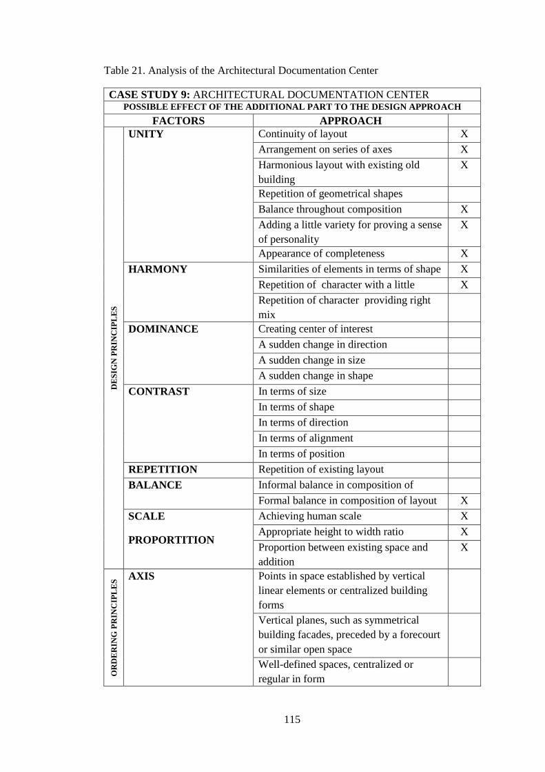
115
Table 21. Analysis of the Architectural Documentation Center
CASE STUDY 9: ARCHITECTURAL DOCUMENTATION CENTER POSSIBLE EFFECT OF THE ADDITIONAL PART TO THE DESIGN APPROACH
FACTORS APPROACH D
ES
IGN
PR
INC
IPL
ES
UNITY Continuity of layout X
Arrangement on series of axes X
Harmonious layout with existing old
building
X
Repetition of geometrical shapes
Balance throughout composition X
Adding a little variety for proving a sense
of personality
X
Appearance of completeness X
HARMONY Similarities of elements in terms of shape X
Repetition of character with a little
variety
X
Repetition of character providing right
mix
DOMINANCE Creating center of interest
A sudden change in direction
A sudden change in size
A sudden change in shape
CONTRAST In terms of size
In terms of shape
In terms of direction
In terms of alignment
In terms of position
REPETITION Repetition of existing layout
BALANCE Informal balance in composition of
layout
Formal balance in composition of layout X
SCALE
PROPORTITION
Achieving human scale X
Appropriate height to width ratio X
Proportion between existing space and
addition
X
OR
DE
RIN
G P
RIN
CIP
LE
S AXIS Points in space established by vertical,
linear elements or centralized building
forms
Vertical planes, such as symmetrical
building facades, preceded by a forecourt
or similar open space
Well-defined spaces, centralized or
regular in form

116
Gateways that open outward toward a
view or vista beyond
X
SYMMETRY Bilateral X
Radial
HIERARCHY By exceptional size
By a unique shape
By strategic location X
DATUM Line
Plane X
Volume
RHYTHM Size
Shape
Detail characteristic
TRANSFORMATION Using existing as prototype
CIR
CU
LA
TIO
N
CONFIGURATION OF
THE PATH
Linear X
Radial
Spiral
Grid
Network
Composite
PATH-SPACE
RELATIONSHIP
Pass by spaces X
Pass through spaces
Terminate in a space
TYPE OF THE
CIRCULATION
ELEMENT
Stair- escalator
Ramp
Bridge
OR
GA
NIZ
AT
ION
TYPE OF
ORGANIZATION
OLD NEW
CENTRAL CENTRAL
LINEAR X LINEAR X
RADIAL RADIAL
CLUSTER CLUSTER
GRIDAL GRIDAL
Adapted from
(Şahin, 2010) ; (URL40)
(Ching, 2002)
(Brooker and Stone, 2004)

117
STRUCTURAL APPROACH
ST
RU
CT
UR
E S
YS
TE
M
FORM ACTIVE VECTOR ACTIVE SECTION ACTIVE SURFACE
ACTIVE Frame:
-Concrete frames
used as the
structural system of
the additional
conference hall.
-Columns are
sitting on the
ground and
supporting the
plane.
MA
TE
RIA
L
STEEL TIMBER R.C. STONE
-Reinforced
concrete is used as
structural material
since it is not a
frequently used
material in the
addition.
-Concrete has left
exposed to give a
dramatic effect in
the old building.
CO
NN
EC
TIO
N
SUSPENDED
FROM EXISTING
STRUCTURE
ATTACHED FREESTANDING COMPLEX
-Additional volume
is a freestanding
element which is
not touching to the
existing walls.
-The plane is
supported with
reinforced concrete
columns in the
existing building.

118
Table 22. General information of the Museum of Local History
CASE STUDY 10 NAME OF THE BUILDING: MUSEUM OF LOCAL HISTORY
LOCATION: HAMBURG
EXISTING ADDITION
CONSTRUCTION DATE : 1913 CONSTRUCTION DATE : 1988
OLD FUNCTION: MUSEUM NEW FUNCTION: MUSEUM
CENTER
ARCHITECT: FRITZ SCHUMACHER ARCHITECT: VON GERKHAN
STRUCTURE SYSTEM: MASONRY STRUCTURE SYSTEM: GRID SHELL
MATERIAL: STONE MATERIAL: STEEL
EXTERIOR VIEW (URL29, 2011) INTERIOR VIEW (Brookes and Grech 1992)
3D MODEL (Brookes and Grech, 1992) ELEVATION (Brookes and Grech, 1992)
PLAN (Brookes and Grech, 1992)
INTEGRATED INSERTED ATTACHED WRAPPED PIERCED
X

119
Table 23. Analysis of the Museum of Local History
CASE STUDY 10: MUSEUM OF LOCAL HISTORY POSSIBLE EFFECT OF THE ADDITIONAL PART TO THE DESIGN APPROACH
FACTORS APPROACH D
ES
IGN
PR
INC
IPL
ES
UNITY Continuity of layout
Arrangement on series of axes
Harmonious layout with existing old
building
Repetition of geometrical shapes
Balance throughout composition
Adding a little variety for proving a sense
of personality
X
Appearance of completeness X
HARMONY Similarities of elements in terms of shape
Repetition of character with a little
variety
Repetition of character providing right
mix
DOMINANCE Creating center of interest X
A sudden change in direction
A sudden change in size X
A sudden change in shape X
CONTRAST In terms of size X
In terms of shape X
In terms of direction
In terms of alignment
In terms of position X
REPETITION Repetition of existing layout
BALANCE Informal balance in composition of
layout
Formal balance in composition of layout X
SCALE
PROPORTITION
Achieving human scale X
Appropriate height to width ratio X
Proportion between existing space and
addition
OR
DE
RIN
G P
RIN
CIP
LE
S AXIS Points in space established by vertical,
linear elements or centralized building
forms
Vertical planes, such as symmetrical
building facades, preceded by a forecourt
or similar open space
Well-defined spaces, centralized or
regular in form
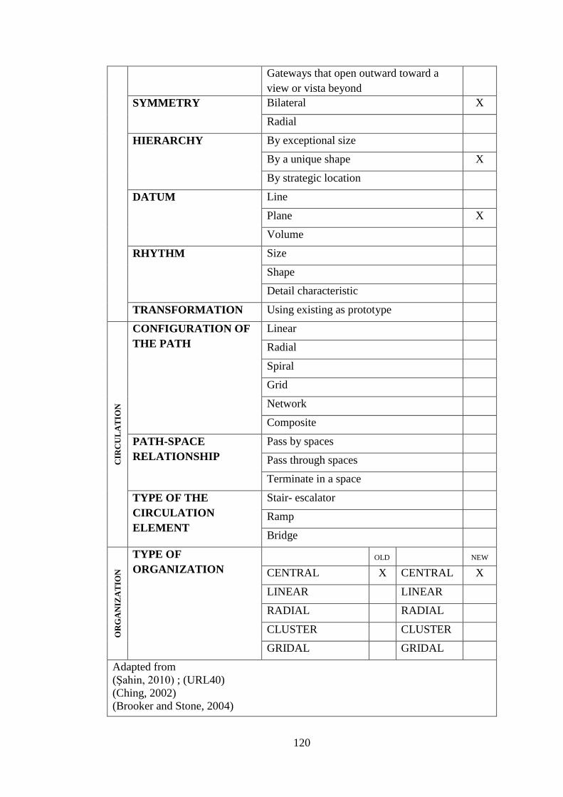
120
Gateways that open outward toward a
view or vista beyond
SYMMETRY Bilateral X
Radial
HIERARCHY By exceptional size
By a unique shape X
By strategic location
DATUM Line
Plane X
Volume
RHYTHM Size
Shape
Detail characteristic
TRANSFORMATION Using existing as prototype
CIR
CU
LA
TIO
N
CONFIGURATION OF
THE PATH
Linear
Radial
Spiral
Grid
Network
Composite
PATH-SPACE
RELATIONSHIP
Pass by spaces
Pass through spaces
Terminate in a space
TYPE OF THE
CIRCULATION
ELEMENT
Stair- escalator
Ramp
Bridge
OR
GA
NIZ
AT
ION
TYPE OF
ORGANIZATION
OLD NEW
CENTRAL X CENTRAL X
LINEAR LINEAR
RADIAL RADIAL
CLUSTER CLUSTER
GRIDAL GRIDAL
Adapted from
(Şahin, 2010) ; (URL40)
(Ching, 2002)
(Brooker and Stone, 2004)

121
STRUCTURAL APPROACH
ST
RU
CT
UR
E S
YS
TE
M
FORM ACTIVE VECTOR ACTIVE SECTION ACTIVE SURFACE
ACTIVE Grid Shell:
-Steel elements
are repeated in
two ways to form
the grid shell
surface.
-The structure
allows spanning
the distances
without any
column.
-Roof is
supported at some
points with
tension cables.
MA
TE
RIA
L
STEEL TIMBER R.C. STONE
-Steel is used as
structural material
and it is covered
with glass to
achieve
transparency.
-A contrast is
created with the use
of steel and glass in
the brick masonry
building.
CO
NN
EC
TIO
N
SUSPENDED
FROM EXISTING
STRUCTURE
ATTACHED FREESTANDING COMPLEX
-Additional roof is
a lightweight grid
shell so it is
attached to the
existing building.
- It is located on the
stone porticos and
supported with
cables.

122
Table 24. General information of the National Museum of Roman Art
CASE STUDY 11 NAME OF THE BUILDING: NATIONAL MUSEUM OF ROMAN ART
LOCATION: MERIDA, SPAIN
EXISTING ADDITION
CONSTRUCTION DATE : 25 BC CONSTRUCTION DATE : 1989
OLD FUNCTION: CITY RUINS NEW FUNCTION: MUSEUM
CENTER
ARCHITECT: UNKNOWN ARCHITECT: RAFAEL MONEO
STRUCTURE SYSTEM: MASONRY STRUCTURE SYSTEM: ARCH
MATERIAL: STONE MATERIAL: STONE
EXTERIOR VIEW (URL30, 2011) INTERIOR VIEW (Brooker and Stone, 2008)
INTERIOR VIEW (URL30, 2011) INTERIOR VIEW (URL30, 2011)
PLAN (Brooker and Stone, 2008)
INTEGRATED INSERTED ATTACHED WRAPPED PIERCED
X

123
Table 25. Analysis of the National Museum of Roman Art
CASE STUDY 11: NATIONAL MUSEUM OF ROMAN ART POSSIBLE EFFECT OF THE ADDITIONAL PART TO THE DESIGN APPROACH
FACTORS APPROACH D
ES
IGN
PR
INC
IPL
ES
UNITY Continuity of layout X
Arrangement on series of axes X
Harmonious layout with existing old
building
X
Repetition of geometrical shapes
Balance throughout composition X
Adding a little variety for proving a sense
of personality
X
Appearance of completeness X
HARMONY Similarities of elements in terms of shape X
Repetition of character with a little
variety
X
Repetition of character providing right
mix
DOMINANCE Creating center of interest
A sudden change in direction
A sudden change in size
A sudden change in shape
CONTRAST In terms of size X
In terms of shape
In terms of direction
In terms of alignment
In terms of position X
REPETITION Repetition of existing layout X
BALANCE Informal balance in composition of
layout
X
Formal balance in composition of layout
SCALE
PROPORTITION
Achieving human scale X
Appropriate height to width ratio X
Proportion between existing space and
addition
X
OR
DE
RIN
G P
RIN
CIP
LE
S AXIS Points in space established by vertical
linear elements or centralized building
forms
Vertical planes, such as symmetrical
building facades, preceded by a forecourt
or similar open space
Well-defined spaces, centralized or
regular in form

124
Gateways that open outward toward a
view or vista beyond
SYMMETRY Bilateral X
Radial
HIERARCHY By exceptional size X
By a unique shape
By strategic location X
DATUM Line
Plane
Volume X
RHYTHM Size
Shape
Detail characteristic
TRANSFORMATION Using existing as prototype X
CIR
CU
LA
TIO
N
CONFIGURATION OF
THE PATH
Linear
Radial
Spiral
Grid X
Network
Composite
PATH-SPACE
RELATIONSHIP
Pass by spaces
Pass through spaces X
Terminate in a space
TYPE OF THE
CIRCULATION
ELEMENT
Stair- escalator
Ramp
Bridge
OR
GA
NIZ
AT
ION
TYPE OF
ORGANIZATION
OLD NEW
CENTRAL CENTRAL
LINEAR LINEAR
RADIAL RADIAL
CLUSTER CLUSTER
GRIDAL X GRIDAL X
Adapted from
(Sahin, 2010) ; (URL40)
(Ching, 2002)
(Brooker and Stone, 2004)
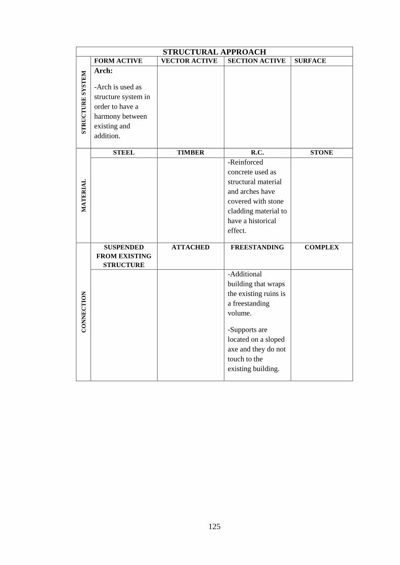
125
STRUCTURAL APPROACH
ST
RU
CT
UR
E S
YS
TE
M
FORM ACTIVE VECTOR ACTIVE SECTION ACTIVE SURFACE
ACTIVE Arch:
-Arch is used as
structure system in
order to have a
harmony between
existing and
addition.
MA
TE
RIA
L
STEEL TIMBER R.C. STONE
-Reinforced
concrete used as
structural material
and arches have
covered with stone
cladding material to
have a historical
effect.
CO
NN
EC
TIO
N
SUSPENDED
FROM EXISTING
STRUCTURE
ATTACHED FREESTANDING COMPLEX
-Additional
building that wraps
the existing ruins is
a freestanding
volume.
-Supports are
located on a sloped
axe and they do not
touch to the
existing building.

126
Table 26. General information of the Santa Catherina Market
CASE STUDY 12 NAME OF THE BUILDING: SANTA CATHERINA MARKET
LOCATION: BARCELONA, SPAIN
EXISTING ADDITION
CONSTRUCTION DATE : 1845 CONSTRUCTION DATE : 2006
OLD FUNCTION: MARKET NEW FUNCTION: MARKET
CENTER
ARCHITECT: UNKNOWN ARCHITECT: EMBT (ENRIC MIRALLES-
BENEDETTA TAGLIABUE)
STRUCTURE SYSTEM: MASONRY STRUCTURE SYSTEM: ARCH
MATERIAL: STONE MATERIAL: TIMBER
EXTERIOR VIEW (Brooker and Stone, 2008) INTERIOR VIEW (URL31, 2011)
3D MODEL (URL31, 2011) FRONT ELEVATION (URL32, 2011)
SITE PLAN (URL1, 2011) SECTION (URL1, 2011)
INTEGRATED INSERTED ATTACHED WRAPPED PIERCED
X

127
Table 27. Analysis of the Santa Catherina Market
CASE STUDY 12: SANTA CATHERINA MARKET POSSIBLE EFFECT OF THE ADDITIONAL PART TO THE DESIGN APPROACH
FACTORS APPROACH D
ES
IGN
PR
INC
IPL
ES
UNITY Continuity of layout
Arrangement on series of axes
Harmonious layout with existing old
building
Repetition of geometrical shapes
Balance throughout composition
Adding a little variety for proving a sense
of personality
X
Appearance of completeness
HARMONY Similarities of elements in terms of shape
Repetition of character with a little
variety
Repetition of character providing right
mix
DOMINANCE Creating center of interest X
A sudden change in direction X
A sudden change in size X
A sudden change in shape X
CONTRAST In terms of size X
In terms of shape X
In terms of direction X
In terms of alignment X
In terms of position X
REPETITION Repetition of existing layout
BALANCE Informal balance in composition of
layout
X
Formal balance in composition of layout
SCALE
PROPORTITION
Achieving human scale X
Appropriate height to width ratio X
Proportion between existing space and
addition
X
OR
DE
RIN
G P
RIN
CIP
LE
S AXIS Points in space established by vertical,
linear elements or centralized building
forms
Vertical planes, such as symmetrical
building facades, preceded by a forecourt
or similar open space
Well-defined spaces, centralized or
regular in form

128
Gateways that open outward toward a
view or vista beyond
SYMMETRY Bilateral X
Radial
HIERARCHY By exceptional size X
By a unique shape X
By strategic location X
DATUM Line
Plane X
Volume
RHYTHM Size
Shape
Detail characteristic
TRANSFORMATION Using existing as prototype
CIR
CU
LA
TIO
N
CONFIGURATION OF
THE PATH
Linear
Radial
Spiral
Grid
Network
Composite
PATH-SPACE
RELATIONSHIP
Pass by spaces
Pass through spaces
Terminate in a space
TYPE OF THE
CIRCULATION
ELEMENT
Stair- escalator
Ramp
Bridge
OR
GA
NIZ
AT
ION
TYPE OF
ORGANIZATION
OLD NEW
CENTRAL CENTRAL
LINEAR LINEAR
RADIAL RADIAL
CLUSTER CLUSTER
GRIDAL X GRIDAL X
Adapted from
(Sahin, 2010) ; (URL40)
(Ching, 2002)
(Brooker and Stone, 2004)

129
STRUCTURAL APPROACH
ST
RU
CT
UR
E S
YS
TE
M
FORM ACTIVE VECTOR ACTIVE SECTION ACTIVE SURFACE
ACTIVE Arch:
-Arch is used as
structure system in
order to have a
harmony between
existing and
addition.
-Steel arches
supported with
trusses vertically at
some points.
Arches transfer the
load through tree
like columns.
MA
TE
RIA
L
STEEL TIMBER R.C. STONE
-Steel is used as
structural material
and it is covered
with glass to
achieve
transparency.
-A contrast is
created with the use
of steel and glass in
the brick masonry
building.
CO
NN
EC
TIO
N
SUSPENDED
FROM EXISTING
STRUCTURE
ATTACHED FREESTANDING COMPLEX
-Additional
building that wraps
the existing
building is a
freestanding plane.
-Supports are
located on a
different axe
system and they do
not touch to the
existing building.

130
Table 28. General information of the Culture and Education Center
CASE STUDY 13 NAME OF THE BUILDING: CULTURE AND EDUCATION CENTER
LOCATION: DEN HELDER,NETHERLAND
EXISTING ADDITION
CONSTRUCTION DATE : - CONSTRUCTION DATE : -
OLD FUNCTION: WAREHOUSE NEW FUNCTION: CULTURE AND
EDUCATION CENTER
CENTER
ARCHITECT: UNKNOWN ARCHITECT: BJARNE MASTENBROEK
STRUCTURE SYSTEM: MASONRY STRUCTURE SYSTEM: FRAME
MATERIAL: STONE MATERIAL: STEEL
EXTERIOR VIEW (Broto, 2004) EXTERIOR VIEW (Broto, 2004)
INTERIOR VIEW (Broto, 2004) 3D MODEL (Broto, 2004)
ELEVATION AND SECTION (Broto, 2004) PLAN (Broto, 2004)
INTEGRATED INSERTED ATTACHED WRAPPED PIERCED
X

131
Table 29. Analysis of the Culture and Education Center
CASE STUDY 13: CULTURE AND EDUCATION CENTER POSSIBLE EFFECT OF THE ADDITIONAL PART TO THE DESIGN APPROACH
FACTORS APPROACH D
ES
IGN
PR
INC
IPL
ES
UNITY Continuity of layout
Arrangement on series of axes
Harmonious layout with existing old
building
Repetition of geometrical shapes
Balance throughout composition
Adding a little variety for proving a sense
of personality
X
Appearance of completeness
HARMONY Similarities of elements in terms of shape
Repetition of character with a little
variety
Repetition of character providing right
mix
DOMINANCE Creating center of interest X
A sudden change in direction X
A sudden change in size X
A sudden change in shape X
CONTRAST In terms of size X
In terms of shape X
In terms of direction X
In terms of alignment
In terms of position X
REPETITION Repetition of existing layout
BALANCE Informal balance in composition of
layout
X
Formal balance in composition of layout
SCALE
PROPORTITION
Achieving human scale X
Appropriate height to width ratio X
Proportion between existing space and
addition
X
OR
DE
RIN
G P
RIN
CIP
LE
S AXIS Points in space established by vertical,
linear elements or centralized building
forms
Vertical planes, such as symmetrical
building facades, preceded by a forecourt
or similar open space
Well-defined spaces, centralized or
regular in form

132
Gateways that open outward toward a
view or vista beyond
SYMMETRY Bilateral
Radial
HIERARCHY By exceptional size X
By a unique shape X
By strategic location X
DATUM Line
Plane X
Volume
RHYTHM Size
Shape
Detail characteristic
TRANSFORMATION Using existing as prototype
CIR
CU
LA
TIO
N
CONFIGURATION OF
THE PATH
Linear
Radial
Spiral
Grid
Network
Composite
PATH-SPACE
RELATIONSHIP
Pass by spaces
Pass through spaces
Terminate in a space
TYPE OF THE
CIRCULATION
ELEMENT
Stair- escalator
Ramp
Bridge
OR
GA
NIZ
AT
ION
TYPE OF
ORGANIZATION
OLD NEW
CENTRAL CENTRAL
LINEAR LINEAR
RADIAL RADIAL
CLUSTER X CLUSTER X
GRIDAL GRIDAL
Adapted from
(Sahin, 2010)
(Ching, 2002)
(Brooker and Stone, 2004)

133
STRUCTURAL APPROACH
ST
RU
CT
UR
E S
YS
TE
M
FORM ACTIVE VECTOR ACTIVE SECTION ACTIVE SURFACE
ACTIVE Frame:
-Steel frames are
used to cover a
group of existing
small buildings.
-Addition is
wrapping the
existing as an
envelope.
MA
TE
RIA
L
STEEL TIMBER R.C. STONE
-Steel is used as
structural material
and it is covered
with glass to
achieve
transparency.
-A contrast is
created with the use
of steel and glass in
the brick masonry
building.
CO
NN
EC
TIO
N
SUSPENDED
FROM EXISTING
STRUCTURE
ATTACHED FREESTANDING COMPLEX
-Additional
building that wraps
the existing
building is a
freestanding plane.
-Supports are
located on a
different axe
system and they do
not touch to the
existing building.

134
Table 30. General information of the Landesusstellung Kärnten
CASE STUDY 14 NAME OF THE BUILDING: LANDESUSSTELLUNG KARNTEN
LOCATION: HUTTENBERG, AUSTURIA
EXISTING ADDITION
CONSTRUCTION DATE : - CONSTRUCTION DATE : -
OLD FUNCTION: FACTORY NEW FUNCTION: CULTURE AND
EXHIBITION CENTER
CENTER
ARCHITECT: UNKNOWN ARCHITECT: GUNTER DOMENIG
STRUCTURE SYSTEM: MASONRY STRUCTURE SYSTEM: FRAME
MATERIAL: STONE MATERIAL: STEEL
EXTERIOR VIEW (Broto, 2004) EXTERIOR VIEW (Broto, 2004)
VIEW FROM BRIDGE (Broto, 2004) 3D SKECTH (Broto, 2004)
PLAN OBLIQUE (Broto, 2004) PARTIAL PLAN (Broto, 2004)
INTEGRATED INSERTED ATTACHED WRAPPED PIERCED
X

135
Table 31. Analysis of the Landesusstellung Kärnten
CASE STUDY 14: LANDESUSSTELLUNG KÄRNTEN POSSIBLE EFFECT OF THE ADDITIONAL PART TO THE DESIGN APPROACH
FACTORS APPROACH
DE
SIG
N P
RIN
CIP
LE
S
UNITY Continuity of layout
Arrangement on series of axes
Harmonious layout with existing old
building
Repetition of geometrical shapes
Balance throughout composition
Adding a little variety for proving a sense
of personality
X
Appearance of completeness
HARMONY Similarities of elements in terms of shape
Repetition of character with a little
variety
Repetition of character providing right
mix
DOMINANCE Creating center of interest X
A sudden change in direction X
A sudden change in size X
A sudden change in shape X
CONTRAST In terms of size X
In terms of shape X
In terms of direction X
In terms of alignment
In terms of position X
REPETITION Repetition of existing layout
BALANCE Informal balance in composition of
layout
X
Formal balance in composition of layout
SCALE
PROPORTITION
Achieving human scale X
Appropriate height to width ratio X
Proportion between existing space and
addition
X
OR
DE
RIN
G P
RIN
CIP
LE
S AXIS Points in space established by vertical,
linear elements or centralized building
forms
Vertical planes, such as symmetrical
building facades, preceded by a forecourt
or similar open space
Well-defined spaces, centralized or
regular in form

136
Gateways that open outward toward a
view or vista beyond
SYMMETRY Bilateral
Radial
HIERARCHY By exceptional size X
By a unique shape X
By strategic location X
DATUM Line
Plane X
Volume
RHYTHM Size
Shape
Detail characteristic
TRANSFORMATION Using existing as prototype
CIR
CU
LA
TIO
N
CONFIGURATION OF
THE PATH
Linear X
Radial
Spiral
Grid
Network
Composite
PATH-SPACE
RELATIONSHIP
Pass by spaces
Pass through spaces
Terminate in a space X
TYPE OF THE
CIRCULATION
ELEMENT
Stair- escalator
Ramp
Bridge X
OR
GA
NIZ
AT
ION
TYPE OF
ORGANIZATION
OLD NEW
CENTRAL CENTRAL
LINEAR LINEAR X
RADIAL RADIAL
CLUSTER X CLUSTER
GRIDAL GRIDAL
Adapted from
(Sahin, 2010) ; (URL40)
(Ching, 2002)
(Brooker and Stone, 2004)

137
STRUCTURAL APPROACH
ST
RU
CT
UR
E S
YS
TE
M
FORM ACTIVE VECTOR ACTIVE SECTION ACTIVE SURFACE
ACTIVE Frame:
-Steel frames are
used as the
structural system of
the circulation
route.
-It is a light
material and it is
easy to construct in
the existing
masonry buildings.
MA
TE
RIA
L
STEEL TIMBER R.C. STONE
-Steel is used as
structural material
and it is covered
with glass to
achieve
transparency.
- A contrast is
created with the use
of steel and glass in
the brick masonry
building.
CO
NN
EC
TIO
N
SUSPENDED
FROM EXISTING
STRUCTURE
ATTACHED FREESTANDING COMPLEX
-Additional
building is a
freestanding
element supported
with columns and
cantilevered at
some point.
-Addition is not
touching to the
existing walls.

138
Table 32. General information of the St. Mary Library
CASE STUDY 15 NAME OF THE BUILDING: ST. MARY LIBRARY
LOCATION: MUNCHEBERG, GERMANY
EXISTING ADDITION
CONSTRUCTION DATE: 13 TH
CENTURY
CONSTRUCTION DATE : 1992
OLD FUNCTION: CHURCH NEW FUNCTION: LIBRARY
CENTER
ARCHITECT: UNKNOWN ARCHITECT: KLAUS BLOCK ARCHITEKT
STRUCTURE SYSTEM: MASONRY STRUCTURE SYSTEM: FRAME
MATERIAL: STONE MATERIAL: STEEL
EXTERIOR VIEW (Broto, 2004) INTERIOR VIEW (Broto, 2004)
3D MODEL (Brooker and Stone, 2007) INTERIOR VIEW (Broto, 2004)
PLAN (Broto, 2004) SECTION (Broto, 2004)
INTEGRATED INSERTED ATTACHED WRAPPED PIERCED
X

139
Table 33. Analysis of the St. Mary Library
CASE STUDY 15: ST. MARY LIBRARY POSSIBLE EFFECT OF THE ADDITIONAL PART TO THE DESIGN APPROACH
FACTORS APPROACH D
ES
IGN
PR
INC
IPL
ES
UNITY Continuity of layout
Arrangement on series of axes
Harmonious layout with existing old
building
Repetition of geometrical shapes
Balance throughout composition X
Adding a little variety for proving a sense
of personality
X
Appearance of completeness X
HARMONY Similarities of elements in terms of shape
Repetition of character with a little
variety
Repetition of character providing right
mix
DOMINANCE Creating center of interest X
A sudden change in direction
A sudden change in size X
A sudden change in shape X
CONTRAST In terms of size X
In terms of shape X
In terms of direction
In terms of alignment
In terms of position
REPETITION Repetition of existing layout
BALANCE Informal balance in composition of
layout
X
Formal balance in composition of layout
SCALE
PROPORTITION
Achieving human scale X
Appropriate height to width ratio
Proportion between existing space and
addition
X
OR
DE
RIN
G P
RIN
CIP
LE
S AXIS Points in space established by vertical,
linear elements or centralized building
forms
Vertical planes, such as symmetrical
building facades, preceded by a forecourt
or similar open space
Well-defined spaces, centralized or
regular in form

140
Gateways that open outward toward a
view or vista beyond
SYMMETRY Bilateral X
Radial
HIERARCHY By exceptional size X
By a unique shape X
By strategic location X
DATUM Line
Plane
Volume
RHYTHM Size
Shape
Detail characteristic
TRANSFORMATION Using existing as prototype
CIR
CU
LA
TIO
N
CONFIGURATION OF
THE PATH
Linear
Radial
Spiral
Grid
Network
Composite
PATH-SPACE
RELATIONSHIP
Pass by spaces
Pass through spaces
Terminate in a space
TYPE OF THE
CIRCULATION
ELEMENT
Stair- escalator
Ramp
Bridge
OR
GA
NIZ
AT
ION
TYPE OF
ORGANIZATION
OLD NEW
CENTRAL CENTRAL
LINEAR X LINEAR X
RADIAL RADIAL
CLUSTER CLUSTER
GRIDAL GRIDAL
Adapted from
(Sahin, 2010) ; (URL40)
(Ching, 2002)
(Brooker and Stone, 2004)

141
STRUCTURAL APPROACH
ST
RU
CT
UR
E S
YS
TE
M
FORM ACTIVE VECTOR ACTIVE SECTION ACTIVE SURFACE
ACTIVE Frame:
- Steel frames are
used as the
structural system of
the addition.
- It is a light
material and it is
easy to construct in
the existing
masonry buildings.
MA
TE
RIA
L
STEEL TIMBER R.C. STONE
-Steel is used as
structural material
and it is covered
with timber.
- A harmony is
created with the use
of timber in the
brick masonry
building.
CO
NN
EC
TIO
N
SUSPENDED
FROM EXISTING
STRUCTURE
ATTACHED FREESTANDING COMPLEX
-Additional
building is a
freestanding
element supported
with columns.
Addition is not
touching to the
existing walls.

142
Table 34. General information of the Rivoli Museum of Contemporary Art
CASE STUDY 16 NAME OF THE BUILDING: RIVOLI MUSEUM OF CONTEMPORARY ART
LOCATION: RIVOLI, ITALY
EXISTING ADDITION
CONSTRUCTION DATE : 18TH
CENTURY
CONSTRUCTION DATE : 1985
OLD FUNCTION: CASTLE NEW FUNCTION: MUSEUM
CENTER
ARCHITECT: FILIPPO JUVARA ARCHITECT: ANDREA BRUNO
STRUCTURE SYSTEM: MASONRY STRUCTURE SYSTEM: FRAME
MATERIAL: STONE MATERIAL: STEEL
EXTERIOR VIEW (Brooker and Stone, 2007) SITE PLAN (Brooker and Stone, 2007)
PLAN (URL33, 2011)
INTEGRATED INSERTED ATTACHED WRAPPED PIERCED
X

143
Table 35. Analysis of the Rivoli Museum of Contemporary Art
CASE STUDY 16: RIVOLI MUSEUM OF CONTEMPORARY ART POSSIBLE EFFECT OF THE ADDITIONAL PART TO THE DESIGN APPROACH
FACTORS APPROACH D
ES
IGN
PR
INC
IPL
ES
UNITY Continuity of layout
Arrangement on series of axes
Harmonious layout with existing old
building
Repetition of geometrical shapes
Balance throughout composition
Adding a little variety for proving a sense
of personality
X
Appearance of completeness X
HARMONY Similarities of elements in terms of shape X
Repetition of character with a little
variety
Repetition of character providing right
mix
DOMINANCE Creating center of interest
A sudden change in direction
A sudden change in size
A sudden change in shape
CONTRAST In terms of size X
In terms of shape X
In terms of direction X
In terms of alignment X
In terms of position X
REPETITION Repetition of existing layout
BALANCE Informal balance in composition of layout X
Formal balance in composition of layout
SCALE
PROPORTITION
Achieving human scale X
Appropriate height to width ratio
Proportion between existing space and
addition
OR
DE
RIN
G P
RIN
CIP
LE
S AXIS Points in space established by vertical,
linear elements or centralized building
forms
Vertical planes, such as symmetrical
building facades, preceded by a forecourt
or similar open space
Well-defined spaces, centralized or
regular in form
X

144
Gateways that open outward toward a
view or vista beyond
SYMMETRY Bilateral
Radial
HIERARCHY By exceptional size X
By a unique shape X
By strategic location X
DATUM Line
Plane
Volume X
RHYTHM Size
Shape
Detail characteristic
TRANSFORMATION Using existing as prototype
CIR
CU
LA
TIO
N
CONFIGURATION OF
THE PATH
Linear X
Radial
Spiral
Grid
Network
Composite
PATH-SPACE
RELATIONSHIP
Pass by spaces
Pass through spaces X
Terminate in a space
TYPE OF THE
CIRCULATION
ELEMENT
Stair- escalator
Ramp
Bridge X
OR
GA
NIZ
AT
ION
TYPE OF
ORGANIZATION
OLD NEW
CENTRAL CENTRAL
LINEAR LINEAR X
RADIAL RADIAL
CLUSTER X CLUSTER
GRIDAL GRIDAL
Adapted from
(Sahin, 2010) ; (URL40)
(Ching, 2002)
(Brooker and Stone, 2004)

145
STRUCTURAL APPROACH
ST
RU
CT
UR
E S
YS
TE
M
FORM ACTIVE VECTOR ACTIVE SECTION ACTIVE SURFACE
ACTIVE Frame:
-Steel frames are
used as the
structural system of
the addition.
- It is a light
material and it is
easy to construct in
the existing
masonry buildings.
MA
TE
RIA
L
STEEL TIMBER R.C. STONE
-Steel is used as
structural material
and it is covered
with glass.
-A contrast is
created with the use
of steel and glass in
the brick masonry
building.
CO
NN
EC
TIO
N
SUSPENDED
FROM EXISTING
STRUCTURE
ATTACHED FREESTANDING COMPLEX
-The Castle floors
are accessed by a
metallic staircase
suspended by steel
tie-beams designed
by the architect.

146
Table 36. General information of the CET Budapest
CASE STUDY 17 NAME OF THE BUILDING: CENTRAL EUROPEAN TIME
LOCATION: BUDAPEST
EXISTING ADDITION
CONSTRUCTION DATE : 19TH
CENTURY
CONSTRUCTION DATE : 2010
OLD FUNCTION: WAREHOUSE NEW FUNCTION: MIXED USE
DEVELOPMENT
CENTER
ARCHITECT: UNKNOWN ARCHITECT: MARTHIJIN POOL
STRUCTURE SYSTEM: MASONRY STRUCTURE SYSTEM: GRID SHELL
MATERIAL: STONE MATERIAL: STEEL
EXTERIOR DETAIL (URL34, 2011) EXTERIOR VIEW (URL34, 2011)
3D MODEL (URL34, 2011) SITE PLAN (URL34, 2011)
SECTION-ELEVATION (URL34, 2011) SECTION (URL34, 2011)
INTEGRATED INSERTED ATTACHED WRAPPED PIERCED
X

147
Table 37. Analysis of the CET Budapest
CASE STUDY 17: CET Budapest POSSIBLE EFFECT OF THE ADDITIONAL PART TO THE DESIGN APPROACH
FACTORS APPROACH D
ES
IGN
PR
INC
IPL
ES
UNITY Continuity of layout
Arrangement on series of axes
Harmonious layout with existing old
building
Repetition of geometrical shapes
Balance throughout composition
Adding a little variety for proving a sense
of personality
Appearance of completeness
HARMONY Similarities of elements in terms of shape
Repetition of character with a little
variety
Repetition of character providing right
mix
DOMINANCE Creating center of interest X
A sudden change in direction
A sudden change in size X
A sudden change in shape X
CONTRAST In terms of size X
In terms of shape X
In terms of direction
In terms of alignment
In terms of position
REPETITION Repetition of existing layout
BALANCE Informal balance in composition of
layout
Formal balance in composition of layout X
SCALE
PROPORTITION
Achieving human scale X
Appropriate height to width ratio X
Proportion between existing space and
addition
X
OR
DE
RIN
G P
RIN
CIP
LE
S AXIS Points in space established by vertical,
linear elements or centralized building
forms
Vertical planes, such as symmetrical
building facades, preceded by a forecourt
or similar open space
Well-defined spaces, centralized or
regular in form

148
Gateways that open outward toward a
view or vista beyond
SYMMETRY Bilateral X
Radial
HIERARCHY By exceptional size
By a unique shape X
By strategic location
DATUM Line
Plane
Volume X
RHYTHM Size
Shape
Detail characteristic
TRANSFORMATION Using existing as prototype
CIR
CU
LA
TIO
N
CONFIGURATION OF
THE PATH
Linear X
Radial
Spiral
Grid
Network
Composite
PATH-SPACE
RELATIONSHIP
Pass by spaces X
Pass through spaces
Terminate in a space
TYPE OF THE
CIRCULATION
ELEMENT
Stair- escalator
Ramp
Bridge
OR
GA
NIZ
AT
ION
TYPE OF
ORGANIZATION
OLD NEW
CENTRAL CENTRAL
LINEAR X LINEAR X
RADIAL RADIAL
CLUSTER CLUSTER
GRIDAL GRIDAL
Adapted from
(Şahin, 2010) ; (URL40)
(Ching, 2002)
(Brooker and Stone, 2004)

149
STRUCTURAL APPROACH
ST
RU
CT
UR
E S
YS
TE
M
FORM ACTIVE VECTOR ACTIVE SECTION ACTIVE SURFACE
ACTIVE Grid Shell:
-Steel elements
are repeated in
two ways to form
the grid shell
surface.
-The structure
allows spanning
the distances
without any
column.
-Transparency is
achieved.
MA
TE
RIA
L
STEEL TIMBER R.C. STONE
-Steel is used as
structural material
and it is covered
with glass.
-A contrast is
created with the use
of steel and glass in
the brick masonry
building.
CO
NN
EC
TIO
N
SUSPENDED
FROM EXISTING
STRUCTURE
ATTACHED FREESTANDING COMPLEX
-Additional
volume is a
freestanding
element which is
not touching to
the existing walls;
however it is
suspended from
some points.

150
Table 38. General information Hedmark Museum & Glass Cathedral
CASE STUDY 18 NAME OF THE BUILDING: HEDMARK MUSEUM & GLASS CATHEDRAL
LOCATION: HAMAR, NORWAY
EXISTING ADDITION
CONSTRUCTION DATE : 13TH CENTURY CONSTRUCTION DATE : 1987
OLD FUNCTION: CATHEDRAL NEW FUNCTION: MUSEUM-
CATHEDRAL
CENTER
ARCHITECT: UNKNOWN ARCHITECT: KJELL LUND
STRUCTURE SYSTEM: MASONRY STRUCTURE SYSTEM: FRAME
MATERIAL: STONE MATERIAL: STEEL
EXISTING BUILDING (URL35, 2011) EXTERIOR VIEW (URL36, 2011)
INTERIOR VIEW (URL1, 2011) PLAN (URL25, 2011)
INTEGRATED INSERTED ATTACHED WRAPPED PIERCED
X

151
Table 39. Analysis of the Hedmark Museum and Glass Cathedral
CASE STUDY 18: HEDMARK MUSEUM & GLASS CATHEDRAL POSSIBLE EFFECT OF THE ADDITIONAL PART TO THE DESIGN APPROACH
FACTORS APPROACH D
ES
IGN
PR
INC
IPL
ES
UNITY Continuity of layout
Arrangement on series of axes
Harmonious layout with existing old
building
Repetition of geometrical shapes
Balance throughout composition
Adding a little variety for proving a sense
of personality
Appearance of completeness
HARMONY Similarities of elements in terms of shape
Repetition of character with a little
variety
Repetition of character providing right
mix
DOMINANCE Creating center of interest X
A sudden change in direction X
A sudden change in size X
A sudden change in shape X
CONTRAST In terms of size X
In terms of shape X
In terms of direction X
In terms of alignment X
In terms of position X
REPETITION Repetition of existing layout
BALANCE Informal balance in composition of
layout
X
Formal balance in composition of layout
SCALE
PROPORTITION
Achieving human scale
Appropriate height to width ratio
Proportion between existing space and
addition
OR
DE
RIN
G P
RIN
CIP
LE
S AXIS Points in space established by vertical,
linear elements or centralized building
forms
Vertical planes, such as symmetrical
building facades, preceded by a forecourt
or similar open space
Well-defined spaces, centralized or
regular in form

152
Gateways that open outward toward a
view or vista beyond
SYMMETRY Bilateral X
Radial
HIERARCHY By exceptional size X
By a unique shape X
By strategic location X
DATUM Line
Plane X
Volume
RHYTHM Size
Shape
Detail characteristic
TRANSFORMATION Using existing as prototype
CIR
CU
LA
TIO
N
CONFIGURATION OF
THE PATH
Linear
Radial
Spiral
Grid
Network
Composite
PATH-SPACE
RELATIONSHIP
Pass by spaces
Pass through spaces
Terminate in a space
TYPE OF THE
CIRCULATION
ELEMENT
Stair- escalator
Ramp
Bridge
OR
GA
NIZ
AT
ION
TYPE OF
ORGANIZATION OLD NEW
CENTRAL X CENTRAL X
LINEAR LINEAR
RADIAL RADIAL
CLUSTER CLUSTER
GRIDAL GRIDAL
Adapted from
(Şahin, 2010) ; (URL40)
(Ching, 2002)
(Brooker and Stone, 2004)

153
STRUCTURAL APPROACH
ST
RU
CT
UR
E S
YS
TE
M
FORM ACTIVE VECTOR ACTIVE SECTION ACTIVE SURFACE
ACTIVE Truss:
-Steel truss is used
as the structural
system of the
addition to span the
large distance over
the ruins.
- It is a light
material and it is
easy to construct in
the existing
masonry buildings.
MA
TE
RIA
L
STEEL TIMBER R.C. STONE
-Steel is used as
structural material
and it is covered
with glass.
-A contrast is
created with the use
of steel and glass in
the brick masonry
building.
CO
NN
EC
TIO
N
SUSPENDED
FROM EXISTING
STRUCTURE
ATTACHED FREESTANDING COMPLEX
-Additional
building is a
freestanding
element supported
with trussed
columns.
- Addition is not
touching to the
existing walls.

154
Table 40. General information of Museum of Contemporary Art
CASE STUDY 19 NAME OF THE BUILDING: MUSEUM OF CONTEMPORARY ART
LOCATION: BERLIN, GERMANY
EXISTING ADDITION
CONSTRUCTION DATE : 1845-47 CONSTRUCTION DATE : 1989-1996
OLD FUNCTION: UNKNOWN NEW FUNCTION: MUSEUM
CENTER
ARCHITECT: FERDINAND WILHELM
HOLZ
ARCHITECT: JOSEF-PAUL KLEIHUES
STRUCTURE SYSTEM: MASONRY STRUCTURE SYSTEM: TRUSSED ARCH
MATERIAL: STONE MATERIAL: STEEL
EXTERIOR VIEW (Powell, 1999) INTERIOR VIEW (Powell, 1999)
INTERIOR VIEW (Powell, 1999)
SECTION (Powell, 1999) PLAN (Powell, 1999)
INTEGRATED INSERTED ATTACHED WRAPPED PIERCED
X

155
Table 41. Analysis of the Museum of Contemporary Art
CASE STUDY 19: MUSEUM OF CONTEMPORARY ART POSSIBLE EFFECT OF THE ADDITIONAL PART TO THE DESIGN APPROACH
FACTORS APPROACH D
ES
IGN
PR
INC
IPL
ES
UNITY Continuity of layout X
Arrangement on series of axes X
Harmonious layout with existing old
building
X
Repetition of geometrical shapes X
Balance throughout composition X
Adding a little variety for proving a sense
of personality
Appearance of completeness X
HARMONY Similarities of elements in terms of shape X
Repetition of character with a little
variety
X
Repetition of character providing right
mix
DOMINANCE Creating center of interest
A sudden change in direction X
A sudden change in size
A sudden change in shape
CONTRAST In terms of size
In terms of shape
In terms of direction
In terms of alignment
In terms of position
REPETITION Repetition of existing layout X
BALANCE Informal balance in composition of
layout
X
Formal balance in composition of layout
SCALE
PROPORTITION
Achieving human scale X
Appropriate height to width ratio X
Proportion between existing space and
addition
X
OR
DE
RIN
G P
RIN
CIP
LE
S AXIS Points in space established by vertical,
linear elements or centralized building
forms
Vertical planes, such as symmetrical
building facades, preceded by a forecourt
or similar open space
Well-defined spaces, centralized or
regular in form

156
Gateways that open outward toward a
view or vista beyond
SYMMETRY Bilateral X
Radial
HIERARCHY By exceptional size
By a unique shape
By strategic location
DATUM Line
Plane
Volume
RHYTHM Size
Shape
Detail characteristic
TRANSFORMATION Using existing as prototype
CIR
CU
LA
TIO
N
CONFIGURATION OF
THE PATH
Linear
Radial
Spiral
Grid
Network
Composite
PATH-SPACE
RELATIONSHIP
Pass by spaces
Pass through spaces
Terminate in a space
TYPE OF THE
CIRCULATION
ELEMENT
Stair- escalator
Ramp
Bridge
OR
GA
NIZ
AT
ION
TYPE OF
ORGANIZATION
OLD NEW
CENTRAL X CENTRAL
LINEAR LINEAR X
RADIAL RADIAL
CLUSTER CLUSTER
GRIDAL GRIDAL
Adapted from
(Sahin, 2010) ; (URL40)
(Ching, 2002)
(Brooker and Stone, 2004)

157
STRUCTURAL APPROACH
ST
RU
CT
UR
E S
YS
TE
M
FORM ACTIVE VECTOR ACTIVE SECTION ACTIVE SURFACE
ACTIVE Truss:
-Steel truss is used
as the structural
system of the
addition.
-It is a light
material and it is
easy to construct in
the existing
masonry buildings.
MA
TE
RIA
L
STEEL TIMBER R.C. STONE
-Steel is used as
structural material
and it is covered
with glass.
-A contrast is
created with the use
of steel and glass in
the brick masonry
building.
CO
NN
EC
TIO
N
SUSPENDED
FROM EXISTING
STRUCTURE
ATTACHED FREESTANDING COMPLEX
-Additional
building is a
freestanding
element supported
with trussed
columns.
-Addition is not
touching to the
existing walls.

158
Table 42. General information of Billingsgate Market
CASE STUDY 20 NAME OF THE BUILDING: BILLINGSGATE MARKET
LOCATION: LONDON, UK
EXISTING ADDITION
CONSTRUCTION DATE : 1874-1877 CONSTRUCTION DATE : 1985
OLD FUNCTION: MARKET NEW FUNCTION: MUSEUM
CENTER
ARCHITECT: SIR HORACE JONES ARCHITECT: RICHARD ROGER
STRUCTURE SYSTEM: MASONRY STRUCTURE SYSTEM: CABLE
MATERIAL: STONE MATERIAL: STEEL
EXTERIOR VIEW (Brookes and Grech, 1992) INTERIOR VIEW (Brookes and Grech, 1992)
GROUND F. PLAN (Brookes and Grech, 1992) FIRST F. PLAN (Brookes and Grech, 1992)
SECTION (Brookes and Grech, 1992)
INTEGRATED INSERTED ATTACHED WRAPPED PIERCED
X

159
Table 43. Analysis of the Billingsgate Market
CASE STUDY 20: BILLINGSGATE MARKET POSSIBLE EFFECT OF THE ADDITIONAL PART TO THE DESIGN APPROACH
FACTORS APPROACH D
ES
IGN
PR
INC
IPL
ES
UNITY Continuity of layout
Arrangement on series of axes X
Harmonious layout with existing old
building
X
Repetition of geometrical shapes X
Balance throughout composition X
Adding a little variety for proving a sense
of personality
Appearance of completeness
HARMONY Similarities of elements in terms of shape X
Repetition of character with a little
variety
Repetition of character providing right
mix
X
DOMINANCE Creating center of interest
A sudden change in direction
A sudden change in size
A sudden change in shape
CONTRAST In terms of size
In terms of shape
In terms of direction
In terms of alignment
In terms of position
REPETITION Repetition of existing layout X
BALANCE Informal balance in composition of
layout
Formal balance in composition of layout X
SCALE
PROPORTITION
Achieving human scale X
Appropriate height to width ratio X
Proportion between existing space and
addition
X
OR
DE
RIN
G P
RIN
CIP
LE
S AXIS Points in space established by vertical,
linear elements or centralized building
forms
Vertical planes, such as symmetrical
building facades, preceded by a forecourt
or similar open space
Well-defined spaces, centralized or
regular in form

160
Gateways that open outward toward a
view or vista beyond
SYMMETRY Bilateral X
Radial
HIERARCHY By exceptional size
By a unique shape
By strategic location
DATUM Line
Plane X
Volume
RHYTHM Size
Shape
Detail characteristic
TRANSFORMATION Using existing as prototype
CIR
CU
LA
TIO
N
CONFIGURATION OF
THE PATH
Linear
Radial
Spiral
Grid
Network
Composite
PATH-SPACE
RELATIONSHIP
Pass by spaces
Pass through spaces
Terminate in a space
TYPE OF THE
CIRCULATION
ELEMENT
Stair- escalator
Ramp
Bridge
OR
GA
NIZ
AT
ION
TYPE OF
ORGANIZATION
OLD NEW
CENTRAL X CENTRAL X
LINEAR LINEAR
RADIAL RADIAL
CLUSTER CLUSTER
GRIDAL GRIDAL
Adapted from
(Şahin, 2010) ; (URL40)
(Ching, 2002)
(Brooker and Stone, 2004)

161
STRUCTURAL APPROACH
ST
RU
CT
UR
E S
YS
TE
M
FORM ACTIVE VECTOR ACTIVE SECTION ACTIVE SURFACE
ACTIVE Cable:
-Mezzanine floors
are supported with
steel cables. There
is no connection
from the floor.
MA
TE
RIA
L
STEEL TIMBER R.C. STONE
-Steel is used as
structural material
and it is covered
with glass.
-A contrast is
created with the use
of steel and glass in
the brick masonry
building.
CO
NN
EC
TIO
N
SUSPENDED
FROM EXISTING
STRUCTURE
ATTACHED FREESTANDING COMPLEX
-Additional
mezzanine floor is
suspended from the
stone columns with
the cables.
5.4 Evaluation of the case studies
All case studies which are analyzed are represented in a single table in order to see
the relation between structures used in the case studies and the types of extension
which is identified as integrated, inserted, attached, wrapped and pierced. Each type
is represented with a different color (Table 44).
162
As the second step, all the possible factors are represented in a common matrix to see
the relationship between structure and the design approach for each case study (Table
45).
Lastly, every case study is colored with the colors of the types that are identified in
Table 44 in order to see the relationship between structure and the design approach
within the groups (Table 46) and the ones that have the same characteristics have
been grouped together. In Table 47 examples which are in the same color (in the
same group) have been put side by side to be able to read the relation better.

163
Table 44. Represents relationship between case studies and the type of the extension
CASE
STUDY
RELATIONSHIP BETWEEN EXISTING AND ADDITION
INTEGRATED INSERTED ATTACHED WRAPPED PIERCED
1
2
3
4
5
6
7
8
9
10
11
12
13
14
15
16
17
18
19
20

164
Table 45. Representation of factors affecting design and structural approach
FACTORS AFFECTING DESIGN APPROACH FACTORS AFFECTING STRUCTURAL APPROACH
CA
SE
ST
UD
Y
DESIGN PRINCIPLES ORDERING PRINCIPLES
OR
GA
NIZ
AT
ION
CIR
CU
LA
TIO
N
STRUCTURE SYSTEM MATERIAL CONNECTION
UN
ITY
HA
RM
ON
Y
DO
MIN
AN
CE
CO
NT
RA
ST
RE
PE
TIT
ION
BA
LA
NC
E
PR
OP
OR
TIO
N
AX
IS
SY
MM
ET
RY
HIE
RA
RC
HY
RH
TY
HM
DA
TU
M
TR
AN
SF
OR
MA
TIO
N
CA
BL
E
TE
NT
AR
CH
TR
US
S
SP
AC
E F
RA
ME
GE
OD
ES
IC D
OM
E
FR
AM
E
SL
AB
FO
LD
ED
PL
AT
E
SH
EL
L
ST
EE
L
TIM
BE
R
R.
CO
NC
RE
TE
ST
ON
E
SU
SP
EN
DE
D
AT
TA
CH
ED
FR
EE
ST
AN
DIN
G
CO
MP
LE
X
1 X - X X - X X X - X - X - X X - - - - - - X - - - X - - - X - - - 2 X X X - X X X - X - - X X - X - - - X - - - - - - X - - - - - X - 3 X - X X - X X X - X - X - X X - - - - - - X - - - - - X - - - X - 4 - - X X - X X - - X - - - - - - - X - - - - - - - - X - - - X - - 5 - - X X - X X - X X - - - - X - - X - - - - - - - X - - - - - - X 6 - - X X - X X - X X - X - - X - - - - - - - - - X X - - - - X - - 7 - - X X - X X - - X - - X - - - - - - - - X - - - X - - - - - X - 8 X - X X - X X - - X - - - - - - - - - X - - - - - - - - - - - X - 9 X X - - - X X X X X - X - - X - - - - - - X - - - - - X - - - X - 10 X - X X - X X - X X - X - - - - - - - - - - - - X X - - - - X - - 11 X X - X X X X - X X - X X - X - - X - - - - - - - - - X - - - X - 12 X - X X - X X - X X - X - - - - - X - - - - - - - X - - - - - X 13 X - X X - X X - - X - X - - - - - - - - - X - - - X - - - - - X - 14 X - X X - X X - - X - X - X X - - - - - - X - - - X - - - - - X - 15 X - X X - X X - X X - - - - - - - - - - - X - - - X - - - - - X - 16 X X - X - X X X - X - X - X X - - - - - - X - - - X - - - X - - - 17 - - X X - X X - X X - X - - X - - - - - - - - - X X - - - - - - X 18 - - X X - X - - X X - X - - - - - - - X - - - - - X - - - - - X - 19 X X X - X X X - X - - - - X - - - - X - - - - - - X - - - - - X - 20 X X - - X X X - X - - X - - - X - - - - - - - - - X - - - X - - -

165
Table 46. Representation of factors affecting design and structural approach within the groups
FACTORS AFFECTING DESIGN APPROACH FACTORS AFFECTING STRUCTURAL APPROACH
CA
SE
ST
UD
Y
DESIGN PRINCIPLES ORDERING PRINCIPLES
OR
GA
NIZ
AT
ION
CIR
CU
LA
TIO
N
STRUCTURE SYSTEM MATERIAL CONNECTION
UN
ITY
HA
RM
ON
Y
DO
MIN
AN
CE
CO
NT
RA
ST
RE
PE
TIT
ION
BA
LA
NC
E
PR
OP
OR
TIO
N
AX
IS
SY
MM
ET
RY
HIE
RA
RC
HY
RH
TY
HM
DA
TU
M
TR
AN
SF
OR
MA
TIO
N
CA
BL
E
TE
NT
AR
CH
TR
US
S
SP
AC
E F
RA
ME
GE
OD
ES
IC D
OM
E
FR
AM
E
SL
AB
FO
LD
ED
PL
AT
E
SH
EL
L
ST
EE
L
TIM
BE
R
R.
CO
NC
RE
TE
ST
ON
E
SU
SP
EN
DE
D
AT
TA
CH
ED
FR
EE
ST
AN
DIN
G
CO
MP
LE
X
1 X - X X - X X X - X - X - X X - - - - - - X - - - X - - - X - - - 2 X X X - X X X - X - - X X - X - - - X - - - - - - X - - - - - X - 3 X - X X - X X X - X - X - X X - - - - - - X - - - - - X - - - X - 4 - - X X - X X - - X - - - - - - - X - - - - - - - - X - - - X - - 5 - - X X - X X - X X - - - - X - - X - - - - - - - X - - - - - - X 6 - - X X - X X - X X - X - - X - - - - - - - - - X X - - - - X - - 7 - - X X - X X - - X - - X - - - - - - - - X - - - X - - - - - X - 8 X - X X - X X - - X - - - - - - - - - X - - - - - - - - - - - X - 9 X X - - - X X X X X - X - - X - - - - - - X - - - - - X - - - X - 10 X - X X - X X - X X - X - - - - - - - - - - - - X X - - - - X - - 11 X X - X X X X - X X - X X - X - - X - - - - - - - - - X - - - X - 12 X - X X - X X - X X - X - - - - - X - - - - - - - X - - - - - X 13 X - X X - X X - - X - X - - - - - - - - - X - - - X - - - - - X - 14 X - X X - X X - - X - X - X X - - - - - - X - - - X - - - - - X - 15 X - X X - X X - X X - - - - - - - - - - - X - - - X - - - - - X - 16 X X - X - X X X - X - X - X X - - - - - - X - - - X - - - X - - - 17 - - X X - X X - X X - X - - X - - - - - - - - - X X - - - - - - X 18 - - X X - X - - X X - X - - - - - - - X - - - - - X - - - - - X - 19 X X X - X X X - X - - - - X - - - - X - - - - - - X - - - - - X - 20 X X - - X X X - X - - X - - - X - - - - - - - - - X - - - X - - -
LEGEND INTEGRATED INSERTED ATTACHED WRAPPED PIERCED

166
Table 47. Representation of factors affecting design and structural approach within the groups side by side
FACTORS AFFECTING DESIGN APPROACH FACTORS AFFECTING STRUCTURAL APPROACH
CA
SE
ST
UD
Y
DESIGN PRINCIPLES ORDERING PRINCIPLES
OR
GA
NIZ
AT
ION
CIR
CU
LA
TIO
N
STRUCTURE SYSTEM MATERIAL CONNECTION
UN
ITY
HA
RM
ON
Y
DO
MIN
AN
CE
CO
NT
RA
ST
RE
PE
TIT
ION
BA
LA
NC
E
PR
OP
OR
TIO
N
AX
IS
SY
MM
ET
RY
HIE
RA
RC
HY
RH
TY
HM
DA
TU
M
TR
AN
SF
OR
MA
TIO
N
CA
BL
E
TE
NT
AR
CH
TR
US
S
SP
AC
E F
RA
ME
GE
OD
ES
IC D
OM
E
FR
AM
E
SL
AB
FO
LD
ED
PL
AT
E
SH
EL
L
ST
EE
L
TIM
BE
R
R.
CO
NC
RE
TE
ST
ON
E
SU
SP
EN
DE
D
AT
TA
CH
ED
FR
EE
ST
AN
DIN
G
CO
MP
LE
X
2 X X X - X X X - X - - X X - X - - - X - - - - - - X - - - - - X - 4 - - X X - X X - - X - - - - - - - X - - - - - - - - X - - - X - - 5 - - X X - X X - X X - - - - X - - X - - - - - - - X - - - - - - X 17 - - X X - X X - X X - X - - X - - - - - - - - - X X - - - - - - X 8 X - X X - X X - - X - - - - - - - - - X - - - - - - - - - - - X - 9 X X - - - X X X X X - X - - X - - - - - - X - - - - - X - - - X - 15 X - X X - X X - X X - - - - - - - - - - - X - - - X - - - - - X - 20 X X - - X X X - X - - X - - - X - - - - - - - - - X - - - X - - - 6 - - X X - X X - X X - X - - X - - - - - - - - - X X - - - - X - - 7 - - X X - X X - - X - - X - - - - - - - - X - - - X - - - - - X - 10 X - X X - X X - X X - X - - - - - - - - - - - - X X - - - - X - - 19 X X X - X X X - X - - - - X - - - - X - - - - - - X - - - - - X - 11 X X - X X X X - X X - X X - X - - X - - - - - - - - - X - - - X - 12 X - X X - X X - X X - X - - - - - X - - - - - - - X - - - - - X 13 X - X X - X X - - X - X - - - - - - - - - X - - - X - - - - - X - 18 - - X X - X - - X X - X - - - - - - - X - - - - - X - - - - - X - 1 X - X X - X X X - X - X - X X - - - - - - X - - - X - - - X - - - 3 X - X X - X X X - X - X - X X - - - - - - X - - - - - X - - - X - 16 X X - X - X X X - X - X - X X - - - - - - X - - - X - - - X - - - 14 X X
-
X X - X X - - X - X - X X - - - - - - X - - - X - - - - - X -
LEGEND INTEGRATED INSERTED ATTACHED WRAPPED PIERCED

167
5.5 Findings
Additions should reflect the date which they are built in terms of innovation,
technology and material. When reflecting its own era, unity between the old and new
must be achieved, either with harmony or contrast. Table 44 represents relationship
between effects and case studies in terms of design approach. Relationship has been
searched within the groups.
In general, case studies which are selected are prime examples which have satisfied
most of the design criteria as shown in Table 45.
In general, steel is the most common used material in additions because it is light,
easy to construct and has a good match in terms of contrast with the stone walls.
However, there are approaches, where timber and reinforced concrete are used in
order to create a harmony between new and old.
In integrated category; dominance, balance and proportion are the mostly used
design principles. Old and new is contrasting, having no unity with each other.
Additions affect the existing circulation of the building; but do not affect
organization. Arch and truss are the mostly used structure systems with complex
connections, where are sometimes suspended and sometimes freestanding.
In the next category, which the new addition is inserted into the existing building,
unity, balance and proportion are the mostly used design principles. Symmetry and
hierarchy are used as ordering elements. In this category there is almost no

168
intervention to circulation and organization. In general, frame is the mostly used
structure system in combination with steel as material in the inserted type of
addition; however there is an approach where additions are suspended with cables
from existing structure. In this category there is no need to span large distances like
in wrapping category.
For the attached category, dominance, balance and proportion are the mostly used
design principles with unity and contrast. Symmetry, hierarchy and datum are used
for ordering elements. In the few examples it affects the circulation and organization.
In the wrapping category, contrast and balance are used as design principles mostly.
There is almost no effect to organization and circulation. Hierarchy and datum are
used to order the elements. Arch, truss, frame and space frame are the mostly used
structural systems where large distances are needed to span without touching to the
existing masonry walls in wrapping category.
For the last category which is pierced, the organization and circulation of the
existing building are affected by the new addition in all examples. Contrast, balance
and proportion are used to achieve unity between the old and the new. Axis,
hierarchy and datum are used as ordering principles. Steel frames are used mostly as
suspended from the existing structure.

169
Chapter 6
EMPIRICAL STUDY
6.1 Selection of the empirical Study
Kadir Has University Cibali Campus Building was selected as the empirical study of
this thesis. The case studies that have been analyzed in the previous chapter contain
only one type of extension. Almost every type of extension, which was identified,
exists in the selected empirical study. The analysis method has been tested through
empirical study and extensions in case studies have been compared with the Kadir
Has University building. Different types of additions in the complex have been
observed and the issues identified in the previous chapters have been discussed.
6.2 History of the building
Cibali Tobacco Factory
(URL37, 2011)
Figure 69. Haliç Silluette in 19th
century
Cibali was built in 19th
century as a tobacco factory next to the Halic Sea by
Ottomans. The construction of the building had started in 1876. The architect of the

170
building was Alexandre Vallaury. It served as a factory until 1995 and closed in 1997
for renovation. Many companies wanted to buy the building to convert it into
different functions because of its strategic location however it had been given to
Kadir Has for conversion of the building from factory to a university building, since
educational functions was more suitable for conservation projects. The project was
given to restorator Dr. Mehmet Alper and it took 3 years to complete the project. In
2000, conversion process had started and 2 years later, at 30 January 2002 building
was opened as Kadir Has University (Alper, 2008).
Tobacco factory in 19th
century
(URL37, 2011)
Tobacco factory in 19th
century
(URL37, 2011)
Figure 70. Tobacco factory before conversion
The project won the Europe Nostra Prize in 2003 with the A and B blocks. As a
restoration philosophy; structure of the building, load bearing parts and originality of
the building had been preserved. The only interventions were about the division of
the space with partitions in the A-B block and the new additions as D block (Alper,
2008).
The most crucial characteristics of the building are its different historic layers. The
building was composed of four different layers. At the basement floor there is a
Byzantine water tank from 13th
century and an Ottoman Bath from the 16th
century,

171
tobacco factory which belongs to the 19th
century and lastly the new extensions
which were added in 2002.
Tobacco factory in 19th
century
(URL37, 2011)
Kadir Has University in 21th
century
(URL37, 2011)
Figure 71. Views before and after conversion
6.3 Analysis of the empirical study
Kadir Has University building has been analyzed with the same method developed in
the previous chapter. In table x, different types of extensions were represented with
different color on the ground floor of Kadir Has University building. Every type of
extension has been analyzed separately and their relation has been discussed by using
mentioned criteria in the previous chapters.

172
Table 48. Different types of extension in the Kadir Has University building
KADIR HAS UNIVERSITY CIBALI CAMPUS BUILDING ( Taken from personal achieve of Dr. Mehmet Alper )
LEGEND
INTEGRATED INSERTED ATTACHED
IN BETWEEN
ATTACHED WRAPPED PIERCED

173
Table 49. General information of the Kadir Has University, A and B Block
EMPIRICAL STUDY: A AND B BLOCK NAME OF THE BUILDING: KADIR HAS UNIVERSITY CIBALI CAMPUS BUILDING
LOCATION: ISTANBUL, TURKEY
EXISTING ADDITION
CONSTRUCTION DATE : 1876 CONSTRUCTION DATE : 2002
OLD FUNCTION: TOBACCO FACTORY NEW FUNCTION: UNIVERSITY
CENTER
ARCHITECT: ALEXANDRE VALLAURY ARCHITECT: MEHMET ALPER
STRUCTURE SYSTEM: MASONRY STRUCTURE SYSTEM: FRAME
MATERIAL: STONE MATERIAL: STEEL
GROUND FLOOR PLAN
FRONT FAÇADE (Photo: Author) LINKAGE (Photo: Author)
INSERTED FLOORS (Photo: Author) STAIRS IN COURTYARD (Photo: Author)
INTEGRATED INSERTED ATTACHED WRAPPED PIERCED
X
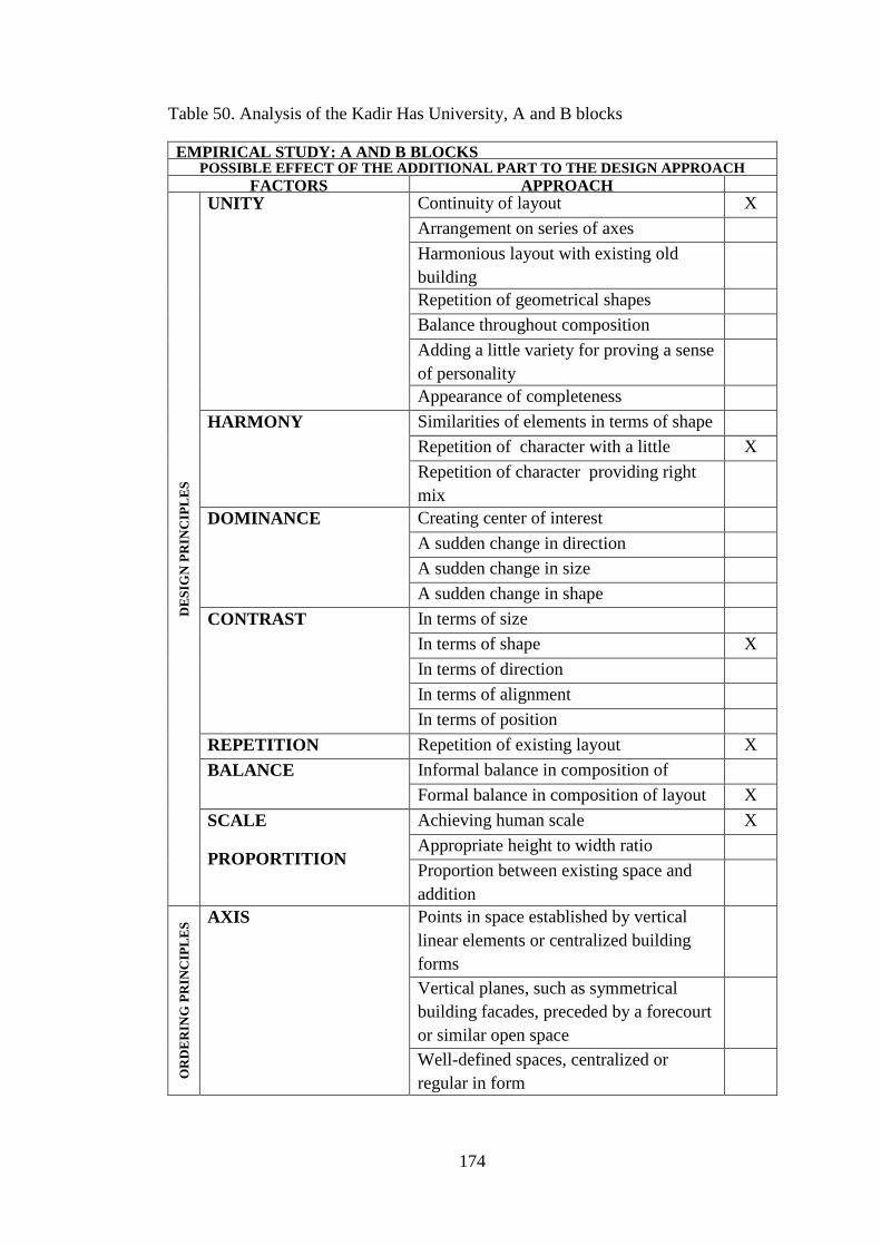
174
Table 50. Analysis of the Kadir Has University, A and B blocks
EMPIRICAL STUDY: A AND B BLOCKS POSSIBLE EFFECT OF THE ADDITIONAL PART TO THE DESIGN APPROACH
FACTORS APPROACH D
ES
IGN
PR
INC
IPL
ES
UNITY Continuity of layout X
Arrangement on series of axes
Harmonious layout with existing old
building
Repetition of geometrical shapes
Balance throughout composition
Adding a little variety for proving a sense
of personality
Appearance of completeness
HARMONY Similarities of elements in terms of shape
Repetition of character with a little
variety
X
Repetition of character providing right
mix
DOMINANCE Creating center of interest
A sudden change in direction
A sudden change in size
A sudden change in shape
CONTRAST In terms of size
In terms of shape X
In terms of direction
In terms of alignment
In terms of position
REPETITION Repetition of existing layout X
BALANCE Informal balance in composition of
layout
Formal balance in composition of layout X
SCALE
PROPORTITION
Achieving human scale X
Appropriate height to width ratio
Proportion between existing space and
addition
OR
DE
RIN
G P
RIN
CIP
LE
S AXIS Points in space established by vertical
linear elements or centralized building
forms
Vertical planes, such as symmetrical
building facades, preceded by a forecourt
or similar open space
Well-defined spaces, centralized or
regular in form

175
Gateways that open outward toward a
view or vista beyond
SYMMETRY Bilateral
Radial
HIERARCHY By exceptional size
By a unique shape
By strategic location
DATUM Line
Plane X
Volume
RHYTHM Size
Shape
Detail characteristic
TRANSFORMATION Using existing as prototype
CIR
CU
LA
TIO
N
CONFIGURATION OF
THE PATH
Linear
Radial
Spiral
Grid
Network
Composite
PATH-SPACE
RELATIONSHIP
Pass by spaces
Pass through spaces
Terminate in a space
TYPE OF THE
CIRCULATION
ELEMENT
Stair- escalator
Ramp
Bridge
OR
GA
NIZ
AT
ION
TYPE OF
ORGANIZATION
OLD NEW
CENTRAL X CENTRAL X
LINEAR LINEAR
RADIAL RADIAL
CLUSTER CLUSTER
GRIDAL GRIDAL
Adapted from
(Sahin, 2010) ; (URL40)
(Ching, 2002)
(Brooker and Stone, 2004)

176
STRUCTURAL APPROACH
ST
RU
CT
UR
E S
YS
TE
M
FORM ACTIVE VECTOR ACTIVE SECTION ACTIVE SURFACE
ACTIVE Frame:
-Steel frames are
used as the
structural system of
the addition.
-It is a light
material and it is
easy to construct in
the existing
masonry buildings.
MA
TE
RIA
L
STEEL TIMBER R.C. STONE
-Steel is used as
structural material.
-A contrast is
created with the use
of steel in the
masonry building.
CO
NN
EC
TIO
N
SUSPENDED
FROM EXISTING
STRUCTURE
ATTACHED FREESTANDING COMPLEX
-Additional floors
are freestanding
elements supported
with steel columns.
-It is not touching
to the existing
walls.

177
Table 51. General information of the Kadir Has University, The bridge
EMPIRICAL STUDY: THE BRIDGE NAME OF THE BUILDING: KADIR HAS UNIVERSITY CIBALI CAMPUS BUILDING
LOCATION: ISTANBUL, TURKEY
EXISTING ADDITION
CONSTRUCTION DATE : 1876 CONSTRUCTION DATE : 2002
OLD FUNCTION: TOBACCO FACTORY NEW FUNCTION: UNIVERSITY
CENTER
ARCHITECT: ALEXANDRE VALLAURY ARCHITECT: MEHMET ALPER
STRUCTURE SYSTEM: MASONRY STRUCTURE SYSTEM: FRAME
MATERIAL: STONE MATERIAL: STEEL
GROUND FLOOR PLAN
FRONT FAÇADE (Photo: Author) LINKAGE BETWEEN A AND B BLOCKS
(URL38, 2011)
INTEGRATED INSERTED ATTACHED WRAPPED PIERCED
X

178
Table 52. Analysis of the Kadir Has University, bridge extension
EMPIRICAL STUDY: BRIDGE POSSIBLE EFFECT OF THE ADDITIONAL PART TO THE DESIGN APPROACH
FACTORS APPROACH D
ES
IGN
PR
INC
IPL
ES
UNITY Continuity of layout
Arrangement on series of axes
Harmonious layout with existing old
building
Repetition of geometrical shapes
Balance throughout composition
Adding a little variety for proving a sense
of personality
Appearance of completeness
HARMONY Similarities of elements in terms of shape
Repetition of character with a little
variety
Repetition of character providing right
mix
DOMINANCE Creating center of interest X
A sudden change in direction
A sudden change in size
A sudden change in shape
CONTRAST In terms of size
In terms of shape X
In terms of direction
In terms of alignment
In terms of position
REPETITION Repetition of existing layout X
BALANCE Informal balance in composition of
layout
Formal balance in composition of layout X
SCALE
PROPORTITION
Achieving human scale X
Appropriate height to width ratio
Proportion between existing space and
addition
OR
DE
RIN
G P
RIN
CIP
LE
S AXIS Points in space established by vertical
linear elements or centralized building
forms
Vertical planes, such as symmetrical
building facades, preceded by a forecourt
or similar open space
Well-defined spaces, centralized or
regular in form

179
Gateways that open outward toward a
view or vista beyond
SYMMETRY Bilateral
Radial
HIERARCHY By exceptional size
By a unique shape
By strategic location
DATUM Line
Plane
Volume
RHYTHM Size
Shape
Detail characteristic
TRANSFORMATION Using existing as prototype
CIR
CU
LA
TIO
N
CONFIGURATION OF
THE PATH
Linear
Radial
Spiral
Grid
Network
Composite
PATH-SPACE
RELATIONSHIP
Pass by spaces
Pass through spaces
Terminate in a space
TYPE OF THE
CIRCULATION
ELEMENT
Stair- escalator
Ramp
Bridge
OR
GA
NIZ
AT
ION
TYPE OF
ORGANIZATION
OLD NEW
CENTRAL X CENTRAL
LINEAR LINEAR X
RADIAL RADIAL
CLUSTER CLUSTER
GRIDAL GRIDAL
Adapted from
(Sahin, 2010) ; (URL40)
(Ching, 2002)
(Brooker and Stone, 2004)

180
STRUCTURAL APPROACH
ST
RU
CT
UR
E S
YS
TE
M
FORM ACTIVE VECTOR ACTIVE SECTION ACTIVE SURFACE
ACTIVE Frame:
-Steel frames are
used as the
structural system of
the addition.
-It is a light
material and it is
easy to construct in
the existing
masonry buildings.
MA
TE
RIA
L
STEEL TIMBER R.C. STONE
-Steel is used as
structural material.
-A contrast is
created with the use
of steel and glass in
the masonry
building.
CO
NN
EC
TIO
N
SUSPENDED
FROM EXISTING
STRUCTURE
ATTACHED FREESTANDING COMPLEX
-Additional bridge
is attached to the
existing walls of
the building.

181
Table 53. General information of the Kadir Has University, C Block
EMPIRICAL STUDY: C BLOCK NAME OF THE BUILDING: FINE ARTS FACULTY AND REZAN HAS MUSUEM
LOCATION: ISTANBUL, TURKEY
EXISTING ADDITION
CONSTRUCTION DATE : 1876 CONSTRUCTION DATE : 2002
OLD FUNCTION: TOBACCO FACTORY NEW FUNCTION: UNIVERSITY
CENTER
ARCHITECT: ALEXANDRE VALLAURY ARCHITECT: MEHMET ALPER
STRUCTURE SYSTEM: MASONRY STRUCTURE SYSTEM: FRAME
MATERIAL: STONE MATERIAL: STEEL
GROUND FLOOR PLAN
EXTERIOR VIEW (Photo: Author) MUSEUM ENTRANCE (Photo: Author)
EXHIBITION OF FINE ARTS (Photo:
Author)
MUSEUM (URL39, 2011)
INTEGRATED INSERTED ATTACHED WRAPPED PIERCED
X

182
Table 54. Analysis of the Kadir Has University, C block
EMPIRICAL STUDY: C BLOCK POSSIBLE EFFECT OF THE ADDITIONAL PART TO THE DESIGN APPROACH
FACTORS APPROACH D
ES
IGN
PR
INC
IPL
ES
UNITY Continuity of layout X
Arrangement on series of axes
Harmonious layout with existing old
building
Repetition of geometrical shapes
Balance throughout composition
Adding a little variety for proving a sense
of personality
Appearance of completeness
HARMONY Similarities of elements in terms of shape
Repetition of character with a little
variety
Repetition of character providing right
mix
DOMINANCE Creating center of interest
A sudden change in direction
A sudden change in size
A sudden change in shape
CONTRAST In terms of size
In terms of shape X
In terms of direction
In terms of alignment
In terms of position
REPETITION Repetition of existing layout X
BALANCE Informal balance in composition of
layout
Formal balance in composition of layout X
SCALE
PROPORTITION
Achieving human scale X
Appropriate height to width ratio
Proportion between existing space and
addition
X
OR
DE
RIN
G P
RIN
CIP
LE
S AXIS Points in space established by vertical,
linear elements or centralized building
forms
Vertical planes, such as symmetrical
building facades, preceded by a forecourt
or similar open space
Well-defined spaces, centralized or
regular in form
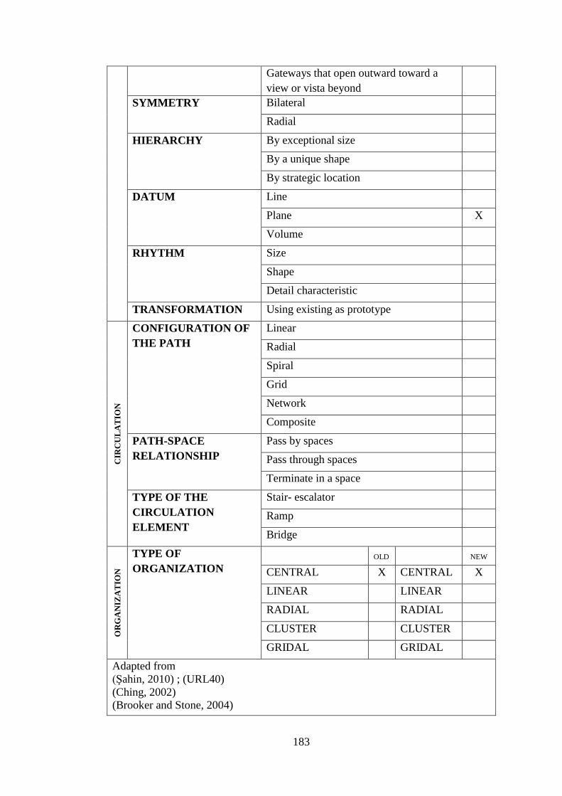
183
Gateways that open outward toward a
view or vista beyond
SYMMETRY Bilateral
Radial
HIERARCHY By exceptional size
By a unique shape
By strategic location
DATUM Line
Plane X
Volume
RHYTHM Size
Shape
Detail characteristic
TRANSFORMATION Using existing as prototype
CIR
CU
LA
TIO
N
CONFIGURATION OF
THE PATH
Linear
Radial
Spiral
Grid
Network
Composite
PATH-SPACE
RELATIONSHIP
Pass by spaces
Pass through spaces
Terminate in a space
TYPE OF THE
CIRCULATION
ELEMENT
Stair- escalator
Ramp
Bridge
OR
GA
NIZ
AT
ION
TYPE OF
ORGANIZATION
OLD NEW
CENTRAL X CENTRAL X
LINEAR LINEAR
RADIAL RADIAL
CLUSTER CLUSTER
GRIDAL GRIDAL
Adapted from
(Şahin, 2010) ; (URL40)
(Ching, 2002)
(Brooker and Stone, 2004)

184
STRUCTURAL APPROACH
ST
RU
CT
UR
E S
YS
TE
M
FORM ACTIVE VECTOR ACTIVE SECTION ACTIVE SURFACE
ACTIVE Frame:
-Steel frames are
used as the
structural system of
the addition.
- It is a light
material and it is
easy to construct in
the existing
masonry buildings.
MA
TE
RIA
L
STEEL TIMBER R.C. STONE
-Steel is used as
structural material.
-A contrast is
created with the use
of steel in the
masonry building.
CO
NN
EC
TIO
N
SUSPENDED
FROM EXISTING
STRUCTURE
ATTACHED FREESTANDING COMPLEX
-Additional floors
are freestanding
elements supported
with columns.
Addition is not
touching to the
existing walls.

185
Table 55. General information of the Kadir Has University, D Block
EMPIRICAL STUDY: D BLOCK NAME OF THE BUILDING: CULTURAL CENTER
LOCATION: ISTANBUL, TURKEY
EXISTING ADDITION
CONSTRUCTION DATE : 1876 CONSTRUCTION DATE : 2002
OLD FUNCTION: TOBACCO FACTORY NEW FUNCTION: UNIVERSITY
CENTER
ARCHITECT: ALEXANDRE VALLAURY ARCHITECT: MEHMET ALPER
STRUCTURE SYSTEM: MASONRY STRUCTURE SYSTEM: FRAME
MATERIAL: STONE MATERIAL: STEEL
GROUND FLOOR PLAN
VIEW FROM THE ROAD (Photo: Author) EXTERIOR VIEW (Photo: Author)
ENTRANCES (Photo: Author) CIRCULATION ELEMENTS IN COURYARD
INTEGRATE
D
INSERTED ATTACHED WRAPPED PIERCED
X

186
Table 56. Analysis of the Kadir Has University, D block
EMPIRICAL STUDY: D BLOCK POSSIBLE EFFECT OF THE ADDITIONAL PART TO THE DESIGN APPROACH
FACTORS APPROACH D
ES
IGN
PR
INC
IPL
ES
UNITY Continuity of layout X
Arrangement on series of axes
Harmonious layout with existing old
building
X
Repetition of geometrical shapes X
Balance throughout composition X
Adding a little variety for proving a sense
of personality
Appearance of completeness
HARMONY Similarities of elements in terms of shape X
Repetition of character with a little
variety
X
Repetition of character providing right
mix
DOMINANCE Creating center of interest
A sudden change in direction
A sudden change in size
A sudden change in shape
CONTRAST In terms of size
In terms of shape
In terms of direction
In terms of alignment
In terms of position
REPETITION Repetition of existing layout X
BALANCE Informal balance in composition of
layout
Formal balance in composition of layout X
SCALE
PROPORTITION
Achieving human scale X
Appropriate height to width ratio
Proportion between existing space and
addition
X
OR
DE
RIN
G P
RIN
CIP
LE
S AXIS Points in space established by vertical,
linear elements or centralized building
forms
Vertical planes, such as symmetrical
building facades, preceded by a forecourt
or similar open space
Well-defined spaces, centralized or
regular in form

187
Gateways that open outward toward a
view or vista beyond
SYMMETRY Bilateral X
Radial
HIERARCHY By exceptional size
By a unique shape
By strategic location
DATUM Line
Plane
Volume
RHYTHM Size
Shape
Detail characteristic
TRANSFORMATION Using existing as prototype X
CIR
CU
LA
TIO
N
CONFIGURATION OF
THE PATH
Linear
Radial
Spiral
Grid
Network
Composite
PATH-SPACE
RELATIONSHIP
Pass by spaces
Pass through spaces
Terminate in a space
TYPE OF THE
CIRCULATION
ELEMENT
Stair- escalator
Ramp
Bridge
OR
GA
NIZ
AT
ION
TYPE OF
ORGANIZATION
OLD NEW
CENTRAL X CENTRAL X
LINEAR LINEAR
RADIAL RADIAL
CLUSTER CLUSTER
GRIDAL GRIDAL
Adapted from
(Şahin, 2010) ; (URL40)
(Ching, 2002)
(Brooker and Stone, 2004)

188
STRUCTURAL APPROACH
ST
RU
CT
UR
E S
YS
TE
M
FORM ACTIVE VECTOR ACTIVE SECTION ACTIVE SURFACE
ACTIVE Frame:
-Steel frames are
used as the
structural system of
the addition.
-It is a light
material and it is
easy to construct in
the existing
masonry buildings.
MA
TE
RIA
L
STEEL TIMBER R.C. STONE
-Steel is used as
structural material.
-A contrast is
created with the use
of steel and glass in
the masonry
building.
CO
NN
EC
TIO
N
SUSPENDED
FROM EXISTING
STRUCTURE
ATTACHED FREESTANDING COMPLEX
-Additional
building is a
freestanding
element supported
with columns.
-Addition is not
touching to the
existing walls.

189
Table 57. General information of the Kadir Has University, Transition spaces
EMPIRICAL STUDY NAME OF THE BUILDING: TRANSITION SPACES
LOCATION: ISTANBUL, TURKEY
EXISTING ADDITION
CONSTRUCTION DATE : 1876 CONSTRUCTION DATE : 2002
OLD FUNCTION: TOBACCO FACTORY NEW FUNCTION: UNIVERSITY
CENTER
ARCHITECT: ALEXANDRE VALLAURY ARCHITECT: MEHMET ALPER
STRUCTURE SYSTEM: MASONRY STRUCTURE SYSTEM: TRUSS
MATERIAL: STONE MATERIAL: STEEL
GROUND FLOOR PLAN
CAFETERIA 2 INTERIOR (Photo: Author) CAFETERIA 1 INTERIOR (Photo: Author)
CAFETERIA 3 INTERIOR (Photo: Author) CAFETERIA 3 EXTERIOR (Photo: Author)
INTEGRATED INSERTED ATTACHED WRAPPED PIERCED
X

190
Table 58. Analysis of the Kadir Has University, Transition spaces
EMPIRICAL STUDY: TRANSITION SPACES POSSIBLE EFFECT OF THE ADDITIONAL PART TO THE DESIGN APPROACH
FACTORS APPROACH D
ES
IGN
PR
INC
IPL
ES
UNITY Continuity of layout
Arrangement on series of axes
Harmonious layout with existing old
building
Repetition of geometrical shapes
Balance throughout composition
Adding a little variety for proving a sense
of personality
Appearance of completeness
HARMONY Similarities of elements in terms of shape
Repetition of character with a little
variety
Repetition of character providing right
mix
DOMINANCE Creating center of interest
A sudden change in direction
A sudden change in size
A sudden change in shape
CONTRAST In terms of size X
In terms of shape X
In terms of direction
In terms of alignment
In terms of position
REPETITION Repetition of existing layout
BALANCE Informal balance in composition of
layout
Formal balance in composition of layout X
SCALE
PROPORTITION
Achieving human scale X
Appropriate height to width ratio
Proportion between existing space and
addition
X
OR
DE
RIN
G P
RIN
CIP
LE
S AXIS Points in space established by vertical,
linear elements or centralized building
forms
Vertical planes, such as symmetrical
building facades, preceded by a forecourt
or similar open space
Well-defined spaces, centralized or
regular in form

191
Gateways that open outward toward a
view or vista beyond
SYMMETRY Bilateral X
Radial
HIERARCHY By exceptional size
By a unique shape
By strategic location
DATUM Line
Plane
Volume
RHYTHM Size
Shape
Detail characteristic
TRANSFORMATION Using existing as prototype
CIR
CU
LA
TIO
N
CONFIGURATION OF
THE PATH
Linear
Radial
Spiral
Grid
Network
Composite
PATH-SPACE
RELATIONSHIP
Pass by spaces
Pass through spaces
Terminate in a space
TYPE OF THE
CIRCULATION
ELEMENT
Stair- escalator
Ramp
Bridge
OR
GA
NIZ
AT
ION
TYPE OF
ORGANIZATION
OLD NEW
CENTRAL X CENTRAL X
LINEAR LINEAR
RADIAL RADIAL
CLUSTER CLUSTER
GRIDAL GRIDAL
Adapted from
(Şahin, 2010) ; (URL40)
(Ching, 2002)
(Brooker and Stone, 2004)

192
STRUCTURAL APPROACH
ST
RU
CT
UR
E S
YS
TE
M
FORM ACTIVE VECTOR ACTIVE SECTION ACTIVE SURFACE
ACTIVE Truss:
-Steel truss are used
as the structural
system of the
addition.
-It is used to span
the distance
without vertical
support.
MA
TE
RIA
L
STEEL TIMBER R.C. STONE
-Steel is used as
structural material.
-A contrast is
created with the use
of steel and glass in
the masonry
building.
CO
NN
EC
TIO
N
SUSPENDED
FROM EXISTING
STRUCTURE
ATTACHED FREESTANDING COMPLEX
-Additional
building is a
freestanding
element supported
with columns.
-Addition is not
touching to the
existing walls.
6.3 Discussions about the Kadir Has University building
The building has a linear organization, creating a silhouette facing with the Haliç
Sea. It is composed of four blocks. A and B blocks are the renovated factory parts of
the complex. A block is functioned as administration, and B block is functioned as
educational activities which are linked with a new addition, serving as cafe. These
additions are attached type of extensions with some differences in comparison to the

193
attached examples that have been discussed in the analysis part (Table 48). In the
case studies the analyzed, extensions were attachments either horizontal or vertical,
but in this example, additions are linking two spaces each other. The extension which
is used as cafeteria 1 is linking two existing blocks, A and B blocks, together serving
as a transition space. The other extension which is used as cafeteria 3 is linking
existing A block and the new extension, D block.
The trussed roof of the cafe addition is contrasting with the heavy load bearing
masonry walls of the existing factory building but there is no unity between existing
building and the extension. There are two more transition spaces, designed with the
same linear organization parallel to each other acting as linkage of the different parts
with different historic layers, shown in Table 48.
The bridge addition in the first floor is a pierced type of extension which links A and
B blocks. In the other examples, which are analyzed in the previous chapter, piercing
extension served as a circulation route inserted in the building; but in this example, it
acts as a linkage of two spaces. It has a steel frame structure, covered with glass and
attached to the existing building. Transparency is achieved with the use of steel and
glass; and it creates a contrast with the solid masonry wall.
The existing old floors of the block was knocked down during restoration because
they were unsuccessful additions built after construction of the factory and did not
have the same language with the existing. The vertical walls have been preserved and
new planes were inserted as new floors; and supported with the steel columns. New
required spaces were created with the partition walls (Figure 72).

194
View from the administration block
(Photo: Author)
Figure 72. Additional floors supported with steel columns
C block is the museum and fine arts part of the complex. At the basement floor there
is a Byzantine water tank from 13th
century which is still under restoration and will
be opened next year and besides an Ottoman Bath from the 16th
century. This floor is
the museum part of the block.
Rezan Has Museum under construction
(URL39, 2011)
Figure 73. Construction process of the museum block
Different exhibitions take place in the museum, but visitors can visit the bath as well
as the museum. The Fine Arts Faculty of the university is built above this museum
which is another conversion. The vertical walls have been preserved and new planes,
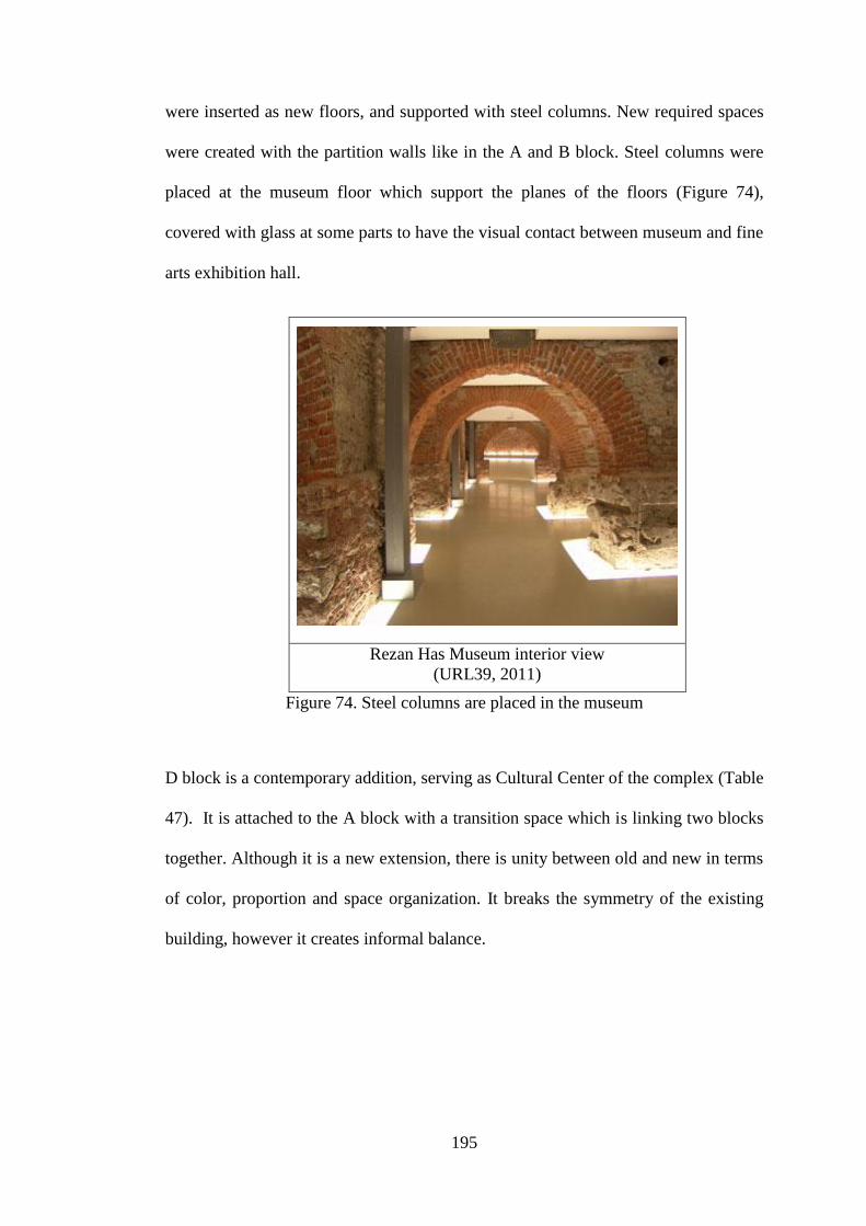
195
were inserted as new floors, and supported with steel columns. New required spaces
were created with the partition walls like in the A and B block. Steel columns were
placed at the museum floor which support the planes of the floors (Figure 74),
covered with glass at some parts to have the visual contact between museum and fine
arts exhibition hall.
Rezan Has Museum interior view
(URL39, 2011)
Figure 74. Steel columns are placed in the museum
D block is a contemporary addition, serving as Cultural Center of the complex (Table
47). It is attached to the A block with a transition space which is linking two blocks
together. Although it is a new extension, there is unity between old and new in terms
of color, proportion and space organization. It breaks the symmetry of the existing
building, however it creates informal balance.
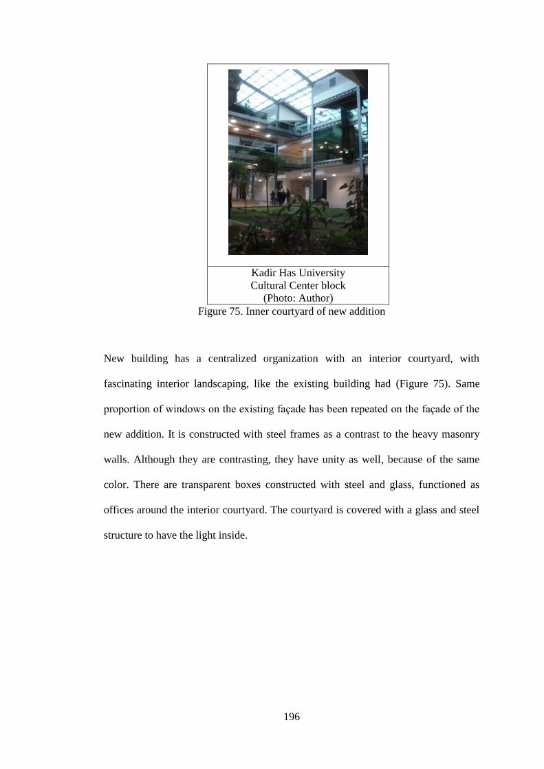
196
Kadir Has University
Cultural Center block
(Photo: Author)
Figure 75. Inner courtyard of new addition
New building has a centralized organization with an interior courtyard, with
fascinating interior landscaping, like the existing building had (Figure 75). Same
proportion of windows on the existing façade has been repeated on the façade of the
new addition. It is constructed with steel frames as a contrast to the heavy masonry
walls. Although they are contrasting, they have unity as well, because of the same
color. There are transparent boxes constructed with steel and glass, functioned as
offices around the interior courtyard. The courtyard is covered with a glass and steel
structure to have the light inside.

197
Chapter 7
CONCLUSION
Reusing and remodeling an old building is a worthy challenge since having different
layers on a single building makes buildings unique and charming in terms of identity.
Combination of old and new is a problem when remodeling old buildings. This
combination refers physical combination and combination in terms of design. In this
study, remodeled buildings have been analyzed in two parts; in the first part of the
thesis, selected case studies are analyzed as type of the structure system, material of
the extension and the connection type of the new and old. In the second part, they are
analyzed in terms of design approaches according to selected criteria, which were
design principles, ordering principles, organization and circulation. Their relation
and effect to each other have been searched in the analysis part.
Twenty different remodeled buildings were analyzed in the case study to find out
which type of extension is used. The study emphasize that there are five different
types of additions used in the remodeled buildings. Integrated, attached, inserted,
wrapped and pierced additions are introduced as approaches of extensions through
analysis of case studies.
For each type, case studies are analyzed in terms of structure and design approach. A
common language is searched within the groups. Generally, it is achieved that
additions should reflect the date which they are built in terms of innovation,

198
technology and material. When reflecting its own era, unity between the old and new
must be achieved, either with harmony or contrast.
Kadir Has University campus is a large complex with different types of additions
which are introduced in the thesis. Although old and new are differentiated from
each other, unity, proportion and contrast are achieved when combining old and new.
Existing proportion on the elevations is repeated on the new extension however
contrast is achieved through use of different structure system and materials.
Centralized organization of the existing building was repeated in the new attached
addition to have link between old and new. Existing building has been left
untouched; however the new additions are reflecting the innovation and technology
of their era. Types of extensions identified in the analysis chapter are seen in the
empirical study with some differences. It is a large complex and different types of
extensions exist in the building. Mostly, extensions are used to link different parts of
the existing building in order to achieve appearance of completeness.
In general, there are no dominant elements between the additions. There is no effect
to circulation and organization. The new additions respect the originality of the
building, with the material and the structure system selection and the connection
points.
The study emphasizes constraints that must be cared in extension design; and creates
a reference for the designers who work on existing fabric. Remodeling is a crucial
issue since old buildings are aesthetic, cultural and economic resources. The main
goal of the research is to raise the awareness of the issue, and create a base for the

199
other researchers to develop this study further as a guide line. This study is focused
on the contemporary additions to public masonry buildings, however future studies
can be developed as extensions to contemporary buildings or residential buildings as
well. Additionally one of the types introduced in the thesis can be selected and
analyzed in depth.

200
REFERENCES
1. ALPER, M. (2008) Mehmet Alper ile Cibali Tütün Fabrikası’ndan Kadir Has
Üniversitesi’ne, http://www.mimarizm.com, extracted in 2011
2. AMBROSE, J. (1993) Building Structures, Canada, John Wiley & Sons
3. BROOKER, G. and STONE, S. (2004), Re-readings, London, Riba
Enterprises
4. BROOKER, G. and STONE, S. (2007), Form and Structure, Switzerland,
Ava Publishing
5. BROOKER, G. and STONE, S. (2008), Context and Environment,
Switzerland, Ava Publishing
6. BROOKES, A. and GRECH, C. (1992), Connections, London, Butterworth-
Heinemann
7. BROTO, C. (2004), New Concepts in Renovating, Barcelona, Structure
8. BUCHHOLDT, H. (1999) An introduction to cable roof structures, London,
Thomas Telford
9. CHING F. (2002), Form, Space and Order, Canada, John Wiley and Sons

201
10. CHING, F. (2004) İç Mekan Tasarımı, İstanbul, Yem Kitabevi
11. CRAMER, J. and BREITLING S. (2007), Architecture in Existing Fabric,
London, Birkhauser
12. CRAVEN, J. (2008) Adaptive Reuse of Older Buildings, The Newyork Times
Company, Retrived May 2008 from the Worldwide Web:
http://architecture.about.com/od/adaptiveuse/Adaptive_reuse_of_Older_Build
ings.htm
13. DAVIS, T. (2011) Geodesic Domes, http://www.geometer.org, extracted in
2011
14. DOUGLAS, J. (2006) Building Adaptation, London, Butterworth-Heinemann
Publishing
15. ENGEL, H. (1997) Strüktür Sistemleri, Istanbul, Tasarım Yayın Grubu
16. EVERETT, A. (1994) Materials, London, Longman
17. FEILDEN, B. (2003), Conservation of Historic Building, Oxford,
Architectural Press
18. FOSTER, J. (1994) Structure and Fabric, London, Longman
202
19. GÜNÇE, K. (2007) A Method of Visual Analysis of Architectural Form,
Unpublished Phd Thesis, Eastern Mediterranean University, Gazimağusa
20. HUDTINGTON, C. (2004) The Tensioned Fabric Roof, USA, ASCE Press
21. JODIDIO, P. (2007) 100 Great Extensions and Renovations, Australia,
Images Publishing
22. LATHAM, D. (2000) Creative reuse of buildings, London, Donhead
Publishing
23. MACDONALD, A. (1994) Structure and Architecture, Oxford, Architectural
Press
24. MAGGIE, T. (1997) New Science, New Architecture, London, Architectural
Design
25. MAINSTONE, R. J. (1998) Developments in Structural Form, London,
Architectural Press
26. MEISS, P. (1990) Elements of Architecture, London, Van Nostrand Reinhold
27. MORNEMENT, A. (2007) Extensions, London, Lawrence King Publishing
28. MUTTONI, A. (2006) The art of structures, London, EPFL Press

203
29. ORBAŞLI, A. (2008) Architectural Conservation, London, Blackwell
Publishing
30. POWELL, K. (1999), Architecture Reborn, London, Laurence King
Publishing
31. RAMM, W. (2003) Design of Masonry Structures, Revised 2003 from the
Worldwide Web: http://www.pg.gda.pl, extracted in 2011
32. RAMON (2003) Arch and Vault, Revised 12.10.2003 from the Worldwide
Web: http://www.royalarchmasons.on.ca, extracted in 2011
33. ŞAHİN, N.P. (2010) Arch 583, Unpublished lecture notes, Eastern
Mediterranean University, Gazimağusa
34. SCHITTICH, C. (2003), In Detail Building in Existing Fabric, Berlin,
Birkhauser
35. SMITH, J. HODGINS, J. OPPENHEIM, I. and WITKIN, A. (2002) Creating
Models of Truss Structures with Optimization, Revised 2002 from Worldwide
Web: http://www.people.csail.mit.edu, extracted in 2011
36. SMITHIES, K.W. (1981) Principles of Design in Architecture, Berkshire,
Van Nostrand Reinhold Co.
204
37. STEELE, J. (1992) Architecture for a Changing World, The Aga Khan
Award for Architecture, Academy Additions Publishing
38. TÜRKÇÜ, Ç. (2009) Çağdaş Taşıyıcı Sistemler, İzmir, Birsen Yayınevi
39. URL1: http://www.flickr.com, extracted in 2011
40. URL2: http://www.borusan.com, extracted in 2011
41. URL3: http://www.earth-quoroville.com, extracted in 2011
42. URL4: http://www.ectour.com, extracted in 2011
43. URL5: http://www.sacred-destinations.com, extracted in 2011
44. URL6: http://www.pbs.org, extracted in 2011
45. URL7: http://www.greatbuildings.com, extracted in 2011
46. URL8: http://www.tensinet.com, extracted in 2011
47. URL9: http://blueroof.wordpress.com, extracted in 2011
48. URL10: http://www.wayfairing.info, extracted in 2011
49. URL11: http://www.caudilltrussandmetal.com, extracted in 2011

205
50. URL12: http://www.amiyaco.com, extracted in 2011
51. URL13: http://www.thefullwiki.org, extracted in 2011
52. URL14: http://www.images.yourdictionary.com, extracted in 2011
53. URL15: http://featuresblog.com, extracted in 2011
54. URL16: http://www.minimalisthousedesign.com, extracted in 2011
55. URL17: http://patternpeople.com, extracted in 2011
56. URL18: http://archicagosojouin.blogspot.com, extracted in 2011
57. URL19: http://platedstructures.com, extracted in 2011
58. URL20: http://www.archspace.com, extracted in 2011
59. URL21:http://architectureweek.com, extracted in 2011
60. URL22: http://www.onlyrooms.com, extracted in 2011
61. URL23: http://www.posterguide.com, extracted in 2011
62. URL24: http://www.dezeen.com, extracted in 2011
63. URL25: http://www.arch.mcgill.ca, extracted in 2011

206
64. URL26: http://wallpaperweb.org, extracted in 2011
65. URL27: http://estatesgazette.com, extracted in 2011
66. URL28: http://arkitera.com, extracted in 2011
67. URL29: http://web.uct.ac.za, extracted in 2011
68. URL30: http://people.seas.harvard.edu, extracted in 2011
69. URL31: http://www.frfoto.eu, extracted in 2011
70. URL31: http://barcelonaphotoblog.com, extracted in 2011
71. URL33: http://xihalife.com, extracted in 2011
72. URL34: http://www.zavobig.com, extracted in 2011
73. URL35: http://maps.thefullwiki.org , extracted in 2011
74. URL36: http://www.hamar.kommune.no, extracted in 2011
75. URL37: http://www.khas.edu.tr, extracted in 2011
76. URL38: http://www.tures.com.tr, extracted in 2011
77. URL39: http://www.mimdap.org, extracted in 2011

207
78. URL 40: http://www.bluemoonwebdesign.com, The principle of Unity,
extracted in 2010
79. WIENAND, N. (2008) Materials, Specification and Detailing, London,
Taylor& Francis

208
APPENDIX

209
Table 59. Kadir Has University Building, Site plan and silhouette
KADIR HAS UNIVERSITY CIBALI CAMPUS BUILDING
SITE PLAN ( Taken from personal achieve of Dr. Mehmet Alper )
HALIC SILHOUETTE ( Taken from personal achieve of Dr. Mehmet Alper )

210
Table 60. Kadir Has University Building, First floor plan
KADIR HAS UNIVERSITY CIBALI CAMPUS BUILDING
FIRST FLOOR PLAN ( Taken from personal achieve of Dr. Mehmet Alper )


![Relationship Between Structure and Architecture Presentation[1]](https://img.pdfslide.us/doc/110x75/577c80441a28abe054a7f3c4/relationship-between-structure-and-architecture-presentation1.jpg)