Embed Size (px)
Citation preview
Applied Bionics and Biomechanics 8 (2011) 1–11DOI 10.3233/ABB-2011-0017IOS Press
1
Analysis of the results from use of hapticpeg-in-hole task for assessmentin neurorehabilitation
Farshid Amirabdollahiana,∗ and Garth Johnsonb
aAdaptive Systems Research Group, The University of Hertfordshire, Hertfordshire, UKbCentre for Rehabilitation and Engineering Studies, School of Mechanical and Systems Engineering,The University of Newcastle, Newcastle, UK
Abstract. Haptic and robotic technologies have the potential to provide assessment during interaction with humans. Thismanuscript presents our earlier research during the I-Match project where a haptic peg-in-hole test was used in order to comparebetween healthy volunteers’ performance and those with neurological impairment. Subjects all performed a series of haptic virtualpeg-in-hole tasks with varying degrees of difficulty determined by the hole diameter. Haptic instrument, Phantom Desktop 1.5,allowed for recording of biomechanical data which is used to present some variant features between the two subject groups.This paper analyses the placement time, maximum peg transfer velocity, collision forces recorded during peg placement andalso insertion accuracy. The first three parameters showed statistically significant differences between the two groups whilethe last, insertion accuracy, showed insignificant differences (p = 0.152). This is thought to be due to the large clearance valuebetween the smallest hole diameter and the peg. To identify differences between the haptic peg-in-hole and the establishedNHPT, we are currently in process of conducting a further experiment with a haptic replica of the NHPT test, in order toinvestigate effects resulting from addition of haptic force feedback compared to the original NHPT test, as well as allowing toexplore influences caused by the 1 mm clearance value as originally proposed by Wade. Furthermore, in order to investigateif this method can identify differences between subjects with different neurological conditions, a larger group of subjects withneurological conditions such as stroke, multiple sclerosis, and traumatic brain injury is required to explore potency of thisapproach for identifying differences between these different conditions.
Keywords: Haptics, peg-in-hole, i-match, robotic for assessment, outcome measures
1. Introduction
The I-Match project, funded by the European Com-mission under the Information Society Technologies(IST) thematic program, was a three-year project thatbegan in November 2002. It focused on quantifying
∗Corresponding author: Dr Farshid Amirabdollahian, MIET,MIEEE, Adaptive Systems Research Group, The University ofHertfordshire, School of Computer Science, College Lane, Hatfield,Hertfordshire, AL10 9AB, UK. Tel.: +44 1707 286 125; Fax: +441707 284 303. E-mail: [email protected].
users’ upper limb performance and skills in order toaid in selecting the most suitable interface for use withhis/her assistive device. The project provided a seriesof haptic tests, including the peg-in-hole test, aiming atdistinguishing the differences seen in between healthyvolunteers and subjects with neurological impairmentwith the longer-term objective of providing accurateand comprehensive measures of precise hand func-tion. This approach also holds the promise of use ina tele-rehabilitation setting where the clinician may beremote from the patient.
1176-2322/11/$27.50 © 2011 – IOS Press and the authors. All rights reserved

2 F. Amirabdollahian and G. Johnson / Analysis of the results from use of haptic peg-in-hole task
This paper presents the peg-in-hole haptic test andproceeds to detail the associated clinical assessment.It then analyses the results using statistical modelsand graphs to support the argument that biomechani-cal parameters identified during haptic interaction canrecord differences observed between different subjectgroups, mainly healthy volunteers versus subjects withneurological conditions.
2. Background
A user’s ability to operate an interface is, to a majordegree, dependent upon the quality of hand and armcontrol. While the commonest method of assessinghand control is to use one of the clinically based scales(e.g. Jebsen et al. [1], Action Research Arm Test [2]),a number of researchers have looked at more quantita-tive approaches. The Southampton Hand AssessmentProcedure (SHAP) is an example of testing hand func-tion in its contextual environment [3]. Using a differenttechnology, Spyers-Ashby and colleagues [4] haveused a six-degrees of freedom electromagnetic sensorto quantify upper limb tremor. In the field of roboticneurorehabilitation, the MIT-MANUS group has usedhaptic approaches to promote and measure upper limbfunction. In studies using their haptic interface, kine-matic data have been used to quantify human armmovements and recovery in stroke patients [5–7]. Sim-ilarly, Reinkensmeyer et al. have used the “Arm Guide”to assess tone, spasticity and lack of coordination forpatients after chronic brain injury [8]. Salazar-Torreset al. used a biomechanical device to investigate theexcitability of muscle stretch reflexes in order to quan-tify spasticity [9]. Moreover, to assess coordinationand upper limb functional state of a group of patientswith different neurological disorders (e.g. FriedreichAtaxia, Parkinson’s disease, Multiple Sclerosis andMuscular Dystrophy), Bardorfer et al. have used aPHANToM haptic interface and a virtual labyrinth[10]. It is acknowledged that the aforementioned stud-ies represent only a small number of the existing andever-growing research aiming to quantify upper limbfunction.
2.1. The haptic peg-in-hole test
The peg-in-hole task consists of two haptically ren-dered holes and a cylindrical peg, which is to bealternately inserted in each hole. Figure 1 shows the
Fig. 1. Visual (on screen) representation of the peg-in-hole task.
graphical user interface presented for this task, cor-relating with dimensions of the haptically renderedmodel.
The test is inspired by the validated and establishedNine-Hole-Peg-Test (NHPT) used in clinical assess-ment. The NHPT requires inserting nine pegs in holesarranged in three rows and three columns. The com-pletion time or the number of pegs inserted in a giventime is seen as a reliable measure of subject’s skills andperformance [11]. As seen in Fig. 1, the haptic peg-in-hole test provides only two holes and uses only one pegduring any one session. It is intentionally designed tobe different from the conventional test as it providesa chance to assess many other aspects of the perfor-mance, for example: it is hypothesized that repetitivemovements to the same positions allow for investigat-ing both repeatability and extent of learning to performbetter; with a two-hole-peg-test where subjects eitherperform a left-to-right or a right-to-left half-cycle, itis possible to compare performance variations towardsand away from the dominant hand, while due to thefreedom given in choosing the pegs in the conventionalNHPT, this is not possible; furthermore the two holesetting also provides a simple base for comparing theperformance using the conventional Fitt’s model formotor control [12].
Haptic presentation of the virtual world is createdusing the PHANToM desktop 1.5 haptic interface fromSensAble Technologies, USA (www.sensable.com).Being developed as a virtual world, the peg-in-hole testalso allows for altering experimental parameters suchas: peg diameter, peg height, peg weight, hole diameter,

F. Amirabdollahian and G. Johnson / Analysis of the results from use of haptic peg-in-hole task 3
Fig. 2. Slicing and sectioning the peg for haptic collision detection.
separation distance between holes and clearance (pegvs. hole). The peg collision with the holes and the othersolid surfaces such as walls shown by Fig. 1 is detectedby detecting collision between these objects and slicesof the peg, which are sectioned as shown by dots inFig. 2. Using a novel mathematical collision detectionalgorithm, multiple contacts between the peg, the tableand holes are detected and haptic feedback is producedupon collisions.
3. Experimental settings and procedures
The PHANToM offers 3 active and 3 passive degreesof freedom. The orientation of the virtual peg mim-icked that of the PHANToM stylus in real-time. Thevirtual table was placed on a horizontal plane as pre-sented in Fig. 1. Shadow cues were used to providebetter depth perception.
The virtual table created for this experiment pre-sented the holes with 150 mm separation distancebetween them. The hole diameter (HD) varied between80 mm, 60 mm or 40 mm resulting in three distinctexperimental settings. The peg diameter was 30 mmleaving a 10 mm clearance between the peg and thesmallest hole.
Participants ranged from healthy volunteers (HV)to subjects recovering from multiple sclerosis (MS),stroke (S) or traumatic brain injury (TBI). Subjectswith neurological impairment were patients at theHunters Moor hospital, Newcastle upon Tyne. Fiftythree subjects participated in the trial. Subjects had noprior knowledge of test objectives and peg-in-hole waspresented as a potential robotic exercise, which couldinfluence recovery. All subjects gave informed consentto participate and could leave the experiment at any
point. From these, 41 subjects completed the exper-iment and their demographic details are presented inTable 1. These resulted in four subject groups: HV, MS,S and TBI. Due to the difficulty of matching subjectnumbers between the three groups with neurologicalimpairments (MS (n = 14), S (n = 2) and TBI (n = 2)),and given that main objective of this study was toinvestigate differences between healthy subjects andthose with neurological conditions, the three groupsare merged as neurological group in this study.
Subject sat comfortably in front of the PHANToMdesktop device as shown in Fig. 3. They were instructedto insert the peg into the left hole, remove it andinsert it into the right hole (starting from mid-position).This was to be performed 20 times (10 cycles) beforemoving to the next experimental setting. They wereinstructed to move as quickly as possible while tryingto minimise the collision with the table and the wallsof the holes during peg placement and removal. Thevisual and auditory cues were also explained. The peginsertion and removal was accompanied by a down-ward or upward guiding arrow presented on the screen
Table 1Subject demographic table
Total Male Female Left Right Agehand hand
Healthy 23 6 17 2 21 38 ± 15Neurological 18 8 10 4 14 51 ± 12Total 41 14 27 6 35 44 ± 15
Fig. 3. Experimental setup.
4 F. Amirabdollahian and G. Johnson / Analysis of the results from use of haptic peg-in-hole task
(shown in Fig. 1). A loud audio beep was also playedonce at each successful peg insertion.
4. Results and analysis
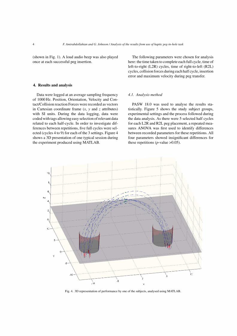
Data were logged at an average sampling frequencyof 1000 Hz. Position, Orientation, Velocity and Con-tact/Collision reaction Forces were recorded as vectorsin Cartesian coordinate frame (x, y and z attributes)with SI units. During the data logging, data werecoded with tags allowing easy selection of relevant datarelated to each half-cycle. In order to investigate dif-ferences between repetitions, five full cycles were sel-ected (cycles 4 to 9) for each of the 3 settings. Figure 4shows a 3D presentation of one typical session duringthe experiment produced using MATLAB.
The following parameters were chosen for analysishere: the time taken to complete each full cycle, time ofleft-to-right (L2R) cycles, time of right-to-left (R2L)cycles, collision forces during each half cycle, insertionerror and maximum velocity during peg transfer.
4.1. Analysis method
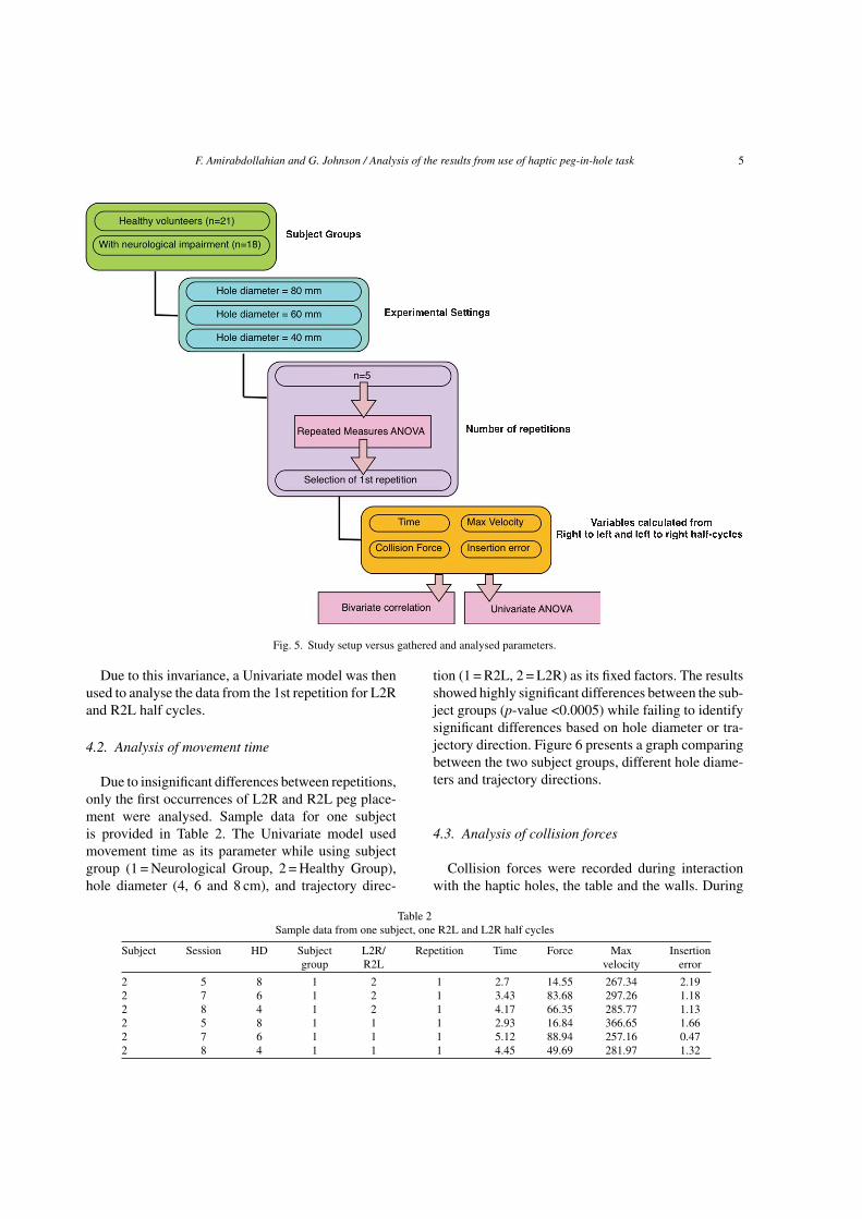
PASW 18.0 was used to analyse the results sta-tistically. Figure 5 shows the study subject groups,experimental settings and the process followed duringthe data analysis. As there were 5 selected half cyclesfor each L2R and R2L peg placement, a repeated mea-sures ANOVA was first used to identify differencesbetween recorded parameters for these repetitions. Allfour parameters showed insignificant differences forthese repetitions (p-value >0.05).
Fig. 4. 3D representation of performance by one of the subjects, analysed using MATLAB.
F. Amirabdollahian and G. Johnson / Analysis of the results from use of haptic peg-in-hole task 5
Fig. 5. Study setup versus gathered and analysed parameters.
Due to this invariance, a Univariate model was thenused to analyse the data from the 1st repetition for L2Rand R2L half cycles.
4.2. Analysis of movement time
Due to insignificant differences between repetitions,only the first occurrences of L2R and R2L peg place-ment were analysed. Sample data for one subjectis provided in Table 2. The Univariate model usedmovement time as its parameter while using subjectgroup (1 = Neurological Group, 2 = Healthy Group),hole diameter (4, 6 and 8 cm), and trajectory direc-
tion (1 = R2L, 2 = L2R) as its fixed factors. The resultsshowed highly significant differences between the sub-ject groups (p-value <0.0005) while failing to identifysignificant differences based on hole diameter or tra-jectory direction. Figure 6 presents a graph comparingbetween the two subject groups, different hole diame-ters and trajectory directions.
4.3. Analysis of collision forces
Collision forces were recorded during interactionwith the haptic holes, the table and the walls. During
Table 2Sample data from one subject, one R2L and L2R half cycles
Subject Session HD Subject L2R/ Repetition Time Force Max Insertiongroup R2L velocity error
2 5 8 1 2 1 2.7 14.55 267.34 2.192 7 6 1 2 1 3.43 83.68 297.26 1.182 8 4 1 2 1 4.17 66.35 285.77 1.132 5 8 1 1 1 2.93 16.84 366.65 1.662 7 6 1 1 1 5.12 88.94 257.16 0.472 8 4 1 1 1 4.45 49.69 281.97 1.32

6 F. Amirabdollahian and G. Johnson / Analysis of the results from use of haptic peg-in-hole task
Fig. 6. Comparing placement time for R2L and L2R half cycles and subject groups.
interaction, such collisions were detected and inter-action forces calculated by the PHANToM device andrecorded using the peg-in-hole program. For each half-cycle, these forces were summed to produce a CollisionForce Vector, used to calculate a resultant collisionforce magnitude for this analysis.
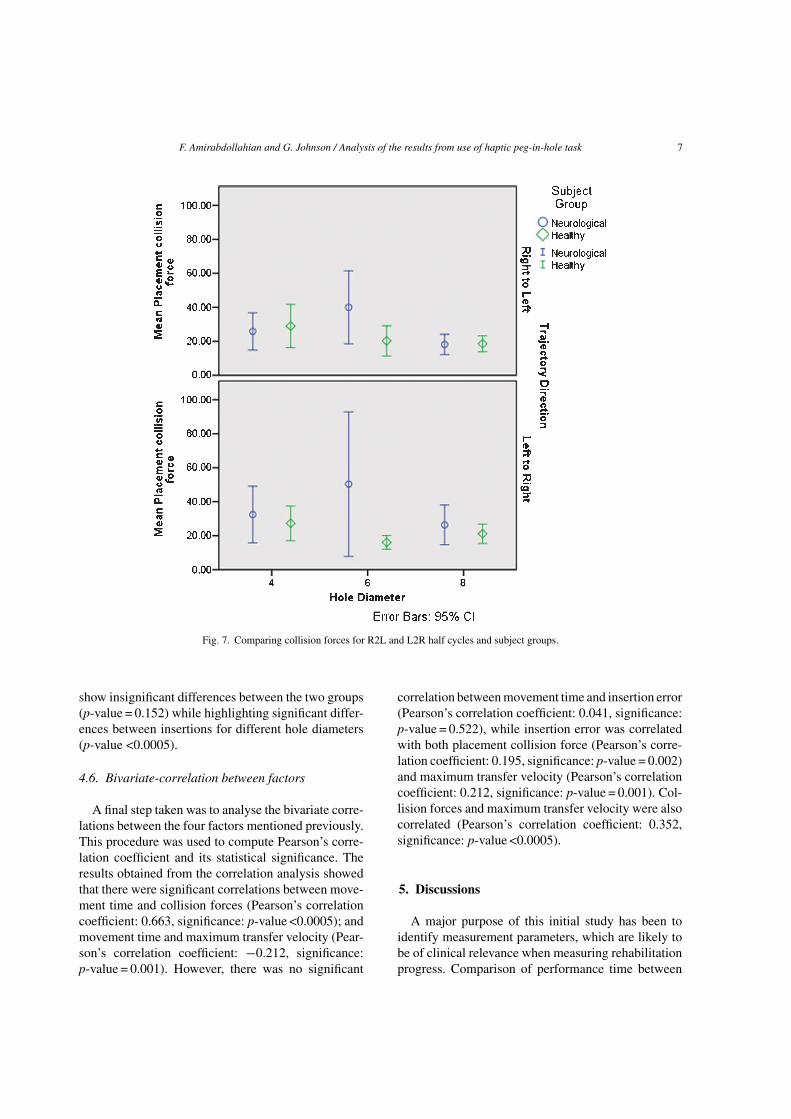
Similar to the movement time, collision force magni-tudes were analysed using the Univariate Model. Thesame parameters were used for this analysis and theresults showed a strong effect for subject group (p-value = 0.016) and interaction between subject groupand hole diameter (p-value = 0.017). These differencesare visually presented by Fig. 7.
4.4. Analysis of maximum transfer velocity
During the interaction, transfer velocity is loggedas a vector in the Cartesian coordinate frame. Themaximum velocity magnitude (MaxVM), was thenfound by a search algorithm during each L2R or
R2L half-cycle. This MaxVM was analysed usingthe Univariate model with the same parameters asmentioned earlier. The results showed significant dif-ferences between the two groups (p-value <0.0005)but failed to highlight differences between L2R andR2L half-cycles, or between different hole-diameters(Fig. 8).
4.5. Analysis of the insertion error
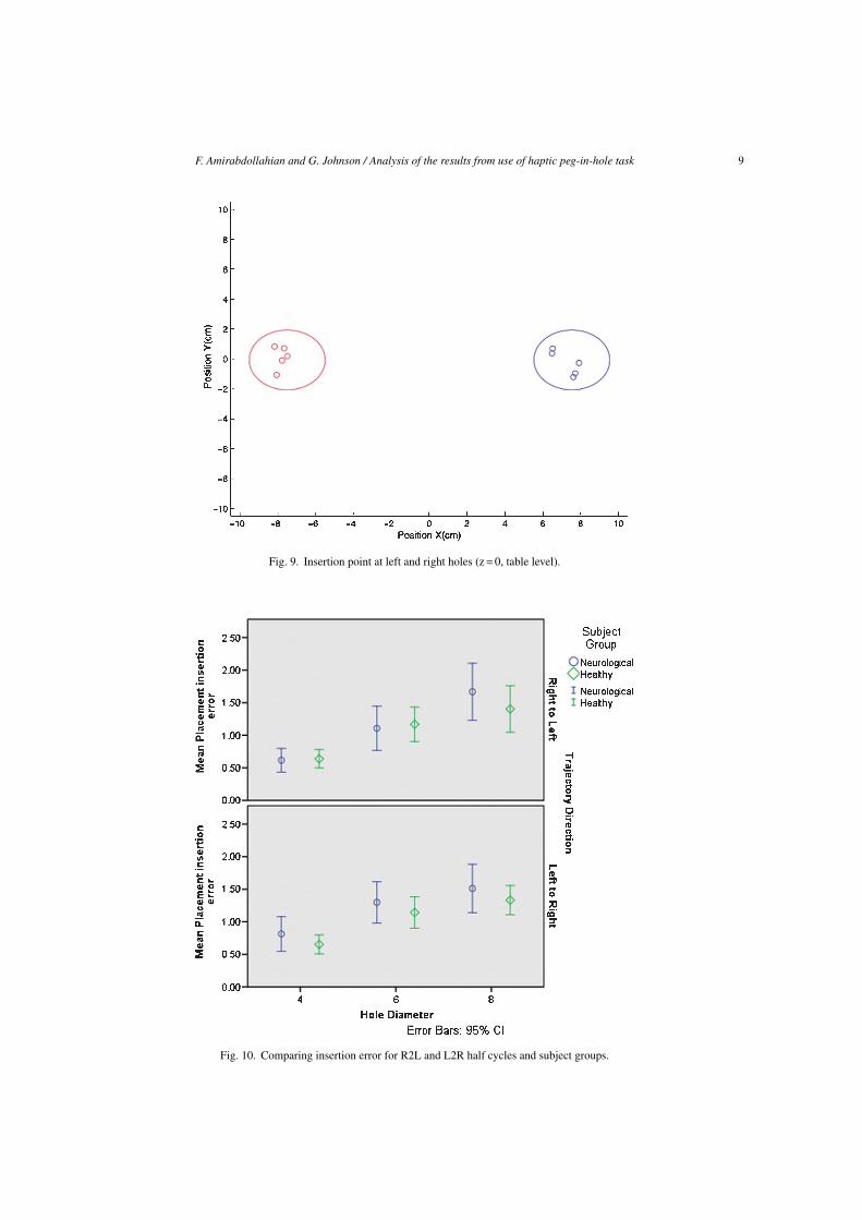
An insertion error was defined as the distancebetween the centre of the peg and the centre of thehole during each insertion into the right or left hole.As a 2D parameter, this was calculated on the hori-zontal plan passing the table surface. Figure 9 presentsthe spread of this error for a single subject where itis clear that this point is not always close to the cen-tre of the hole. This parameter was also analysed tocompare between the two groups, different hole diam-eters and trajectory directions. The results (Fig. 10)
F. Amirabdollahian and G. Johnson / Analysis of the results from use of haptic peg-in-hole task 7
Fig. 7. Comparing collision forces for R2L and L2R half cycles and subject groups.
show insignificant differences between the two groups(p-value = 0.152) while highlighting significant differ-ences between insertions for different hole diameters(p-value <0.0005).
4.6. Bivariate-correlation between factors
A final step taken was to analyse the bivariate corre-lations between the four factors mentioned previously.This procedure was used to compute Pearson’s corre-lation coefficient and its statistical significance. Theresults obtained from the correlation analysis showedthat there were significant correlations between move-ment time and collision forces (Pearson’s correlationcoefficient: 0.663, significance: p-value <0.0005); andmovement time and maximum transfer velocity (Pear-son’s correlation coefficient: −0.212, significance:p-value = 0.001). However, there was no significant
correlation between movement time and insertion error(Pearson’s correlation coefficient: 0.041, significance:p-value = 0.522), while insertion error was correlatedwith both placement collision force (Pearson’s corre-lation coefficient: 0.195, significance: p-value = 0.002)and maximum transfer velocity (Pearson’s correlationcoefficient: 0.212, significance: p-value = 0.001). Col-lision forces and maximum transfer velocity were alsocorrelated (Pearson’s correlation coefficient: 0.352,significance: p-value <0.0005).
5. Discussions
A major purpose of this initial study has been toidentify measurement parameters, which are likely tobe of clinical relevance when measuring rehabilitationprogress. Comparison of performance time between

8 F. Amirabdollahian and G. Johnson / Analysis of the results from use of haptic peg-in-hole task
Fig. 8. Comparing maximum velocity for R2L and L2R half cycles and subject groups.
different subject groups showed significant differencesbetween the unimpaired and patient groups. This trendwas further confirmed by results from collision forceand maximum velocity. However, insertion error failedto support significant differences between the two sub-ject groups. This finding is probably not surprisingsince the test provides no visual or auditory feedback ofinsertion accuracy. Since the clearances are relativelylarge, it is fairly easy for the subject to avoid collisionwith the side of the hole with a small level of preci-sion. This is further supported by the evidence fromPearson’s correlation that movement time was signif-icantly correlated with maximum velocity magnitudeand collision force but not with the insertion error.
As might be expected, insertion error showed strongeffects for the hole diameter, but this was not signif-icantly different between the two groups. Moreover,collision force failed to show strong evidence fordifferences related to hole diameter again suggest-
ing that the relatively large clearance allowed easyinsertion.
Upon studying Figs 6 and 7, it is clear that L2Rportion of the movement time and collision force bothpresent large variations for a 60 mm diameter hole andthe neurological subject group. However, neither ofthe Univariate models have identified subject groupinteraction with trajectory direction as a significantinteraction.
This study has presented proof of concept ideaswhere a clinically established and validated test suchas NHPT can be replicated using the haptic simula-tion. Although movement time here was calculated ina different manner from the traditional test, it was stillcapable of distinguishing differences between differ-ent subjects and subject groups. Similarly, collisionforce and maximum velocity magnitude showed poten-tial for identifying differences between the two subjectgroups.
F. Amirabdollahian and G. Johnson / Analysis of the results from use of haptic peg-in-hole task 9
Fig. 9. Insertion point at left and right holes (z = 0, table level).
Fig. 10. Comparing insertion error for R2L and L2R half cycles and subject groups.

10 F. Amirabdollahian and G. Johnson / Analysis of the results from use of haptic peg-in-hole task
There are clearly some challenges for future devel-opment. While the original NHPT used a 1 mmclearance between the peg and the hole diameter, the10 mm clearance used here is thought to have not posedsignificant challenge illustrated by insignificant differ-ences between the collision forces for different holediameters.
6. Conclusions
This paper has presented a novel haptic test foranalysing performance through interaction. By repli-cating and modifying one of the established clinicalmeasures into a haptic assessment, it has shownthat it is possible to identify differences betweenthe unimpaired group and subjects with neurologicalconditions. This was evident from movement time, col-lision force and maximum velocity magnitude duringpeg transfer. The failure to demonstrate differencesin insertion error is attributed to the use of largeclearances and the absence of feedback for insertionaccuracy.
While the study has shown the ability to distinguishbetween normal subjects and those with impairment,the small numbers of subjects with different neuro-logical conditions made it impossible to investigatedifferences between different pathologies.
Further development and testing are required beforeproposing this test as a suitable replacement for thetraditional Nine-Hole-Peg-Test (NHPT). The majorrequirements are further development of the systemto allow smaller clearances and improved user feed-back followed by larger scale clinical studies allowingvalidation and calibration of this new tool against thetraditional NHPT and other relevant clinical measures.Further work in this area is currently being carriedout to achieve smaller peg clearances and so a closerreplication of the NHPT. In conclusion, the authorsbelieve that rapid developments in haptic technologyhold the promise of higher technology and low costsystems capable of detailed measurement of precisehand function and motor control.
Acknowledgements
We are grateful to all our colleagues in the i-matchconsortium (University of Newcastle upon Tyne, UK;University of Ljubljana, Slovenia; HITEC SNT con-
sultants, Greece; Trinity College Dublin, Ireland; andFondazione Don Gnocchi (S.I.V.A.)), Italy, for theirongoing commitment to this work.
We are also grateful to staff at Hunters Moor hospitalin Newcastle and subjects that agreed to participate inthis study.
Last but not least, we are thankful to Mr GermanoGomes who had contributed to the development of peg-in-hole and its MATLAB analytical procedure from thestart of the project to its end.
References
[1] R.H. Jebsen, N. Taylor and R.B. Trieschmann, An objectiveand standardised test of hand function, Arch Phys Med Re-habil 50 (1969), 311–319.
[2] R.C. Lyle, A performance test for assessment of upper limbfunction in physical rehabilitation treatment and research,International Journal of Rehabilitation Research 4 (1981),483–492.
[3] C.M. Light, P.H. Chappell and P.J. Kyberd, Establishinga standardized clinical assessment tool of pathologic andprosthetic hand function: Normative data, reliability, andvalidity, Archives of Physical Medicine and Rehabilitation83(6) (2002), 776–783.
[4] J.M. Spyers-Ashby, M.J. Stokes, P.G. Bain and S.J. Roberts,Classification of normal and pathological tremors usinga multidimensional electromagnetic system, Medical Engi-neering and Physics 21(10) (1999), 713–723.
[5] H.I. Krebs, M.L. Aisen, B.T. Volpe and N. Hogan, Quanti-zation of continuous arm movements in humans with braininjury, in Proceedings of the National Academy of Sci-ences of the United States of America 1999, pp. 4645–4649.
[6] H.I. Krebs, B.T. Volpe, M.L. Aisen and N. Hogan, In-creasing productivity and quality of care: Robot-aidedneuro-rehabilitation, Journal of Rehabilitation Research andDevelopment 37(6) (2000), 639–652.
[7] H.I. Krebs, N. Hogan, M.L. Aisen and B.T. Volpe, Robot-aided neurorehabilitation, Ieee Transactions on Rehabilita-tion Engineering 6(1) (1998), 75–87.
[8] D.J. Reinkensmeyer, L.E. Kahn, M. Averbuch, A. McKenna-Cole, B.D. Schmit and W.Z. Rymer, Understanding andtreating arm movement impairment after chronic braininjury: Progress with the ARM guide, Journal of Reha-bilitation Research and Development 37(6) (2000), 653–662.
[9] J. Salazar-Torres, A.D. Pandyan, C.I.M. Price, R.I. Davidson,M.P. Barnes and G.R. Johnson, Does spasticity result fromhyperactive stretch reflexes? Preliminary findings from astretch reflex characterization study, Disability and Rehabili-tation 26(12) (2004), 756–760.
[10] A. Bardorfer, M. Munih, A. Zupan and A. Primozic, Upperlimb motion analysis using haptic interface, Ieee Asme Trans-actions on Mechatronics 6(3) (2001), 253–260.
[11] D.T. Wade, Measurement in Neurological Rehabilita-tion, Oxford University Press, Oxford, England, 1992,p. 408.
F. Amirabdollahian and G. Johnson / Analysis of the results from use of haptic peg-in-hole task 11
[12] P.M. Fitts, The information capacity of the human motor sys-tem in controlling the amplitude of movement, Journal ofExperimental Psychology 47 (1954), 381–391.
[13] I.S. MacKenzie, Movement time prediction in human-computer interfaces, in Reading in Human-ComputerInteraction, R.M. Baecker, et al., eds, CA, Kaufmann, 1995,pp. 483–493.
[14] I.S. MacKenzie and W. Buxton, Extending Fitts’ law to two-dimensional tasks, Proceedings of the SIGCHI Conference onHuman Factors in Computing Systems, ACM, New York, NY,USA, 1992, pp. 219–226.
[15] A. Murata and H. Iwase, Extending fitts’ law to a three-dimensional pointing task, Human Movement Science 20(6)(2001), 791–805.

International Journal of
AerospaceEngineeringHindawi Publishing Corporationhttp://www.hindawi.com Volume 2010
RoboticsJournal of
Hindawi Publishing Corporationhttp://www.hindawi.com Volume 2014
Hindawi Publishing Corporationhttp://www.hindawi.com Volume 2014
Active and Passive Electronic Components
Control Scienceand Engineering
Journal of
Hindawi Publishing Corporationhttp://www.hindawi.com Volume 2014
International Journal of
RotatingMachinery
Hindawi Publishing Corporationhttp://www.hindawi.com Volume 2014
Hindawi Publishing Corporation http://www.hindawi.com
Journal ofEngineeringVolume 2014
Submit your manuscripts athttp://www.hindawi.com
VLSI Design
Hindawi Publishing Corporationhttp://www.hindawi.com Volume 2014
Hindawi Publishing Corporationhttp://www.hindawi.com Volume 2014
Shock and Vibration
Hindawi Publishing Corporationhttp://www.hindawi.com Volume 2014
Civil EngineeringAdvances in
Acoustics and VibrationAdvances in
Hindawi Publishing Corporationhttp://www.hindawi.com Volume 2014
Hindawi Publishing Corporationhttp://www.hindawi.com Volume 2014
Electrical and Computer Engineering
Journal of
Advances inOptoElectronics
Hindawi Publishing Corporation http://www.hindawi.com
Volume 2014
The Scientific World JournalHindawi Publishing Corporation http://www.hindawi.com Volume 2014
SensorsJournal of
Hindawi Publishing Corporationhttp://www.hindawi.com Volume 2014
Modelling & Simulation in EngineeringHindawi Publishing Corporation http://www.hindawi.com Volume 2014
Hindawi Publishing Corporationhttp://www.hindawi.com Volume 2014
Chemical EngineeringInternational Journal of Antennas and
Propagation
International Journal of
Hindawi Publishing Corporationhttp://www.hindawi.com Volume 2014
Hindawi Publishing Corporationhttp://www.hindawi.com Volume 2014
Navigation and Observation
International Journal of
Hindawi Publishing Corporationhttp://www.hindawi.com Volume 2014
DistributedSensor Networks
International Journal of