Embed Size (px)
Citation preview
Arica dwi susanto.et.al. Int. Journal of Engineering Research and Application www.ijera.com
ISSN : 2248-9622, Vol. 7, Issue 4, ( Part -6) April 2017, pp.08-15
www.ijera.com DOI: 10.9790/9622-0704060815 8 | P a g e
Analysis of The Propulsion System Towards The Speed
Reduction of Vessels Type PC-43
Arica Dwi Susanto1, Ahmadi
2, Okol S Suharyo
3, Indrajaya Gerianto
4
1Indonesian Naval Technology College, Bumimoro-Morokrembangan, Surabaya 60187, Indonesia
ABSTRACT (PC-43) is an Indonesian navy vessel type limited patrol craft made in Indonesian. The vessel was designed
using a steel material with a maximum speed of 27 knots and using engine power by 3 x 1800 HP, T = 1.40 at
the empty draft and T = 1.70 at full draft. The speed is decreased in the current conditions by 22 knots at 1.50
meters draft within 1 year after its launching. This fact is very interesting to be used as a paper project by
analyzing the effect of changes in vessel’s draft to the resistance and analyze the current installed engine power,
This paper carried two methods of calculation, namely: resistance and power calculation numerically along with
resistance and power calculation using software maxsurf. The results from the manual calculations of power at T
= 1.65 meters in 27 knots, the power needed is BHPscr = 4245.04 HP. From the data of power installed in the
vessel, it was stated that the power is 3 x 1800 = 5400 HP, means a mathematical/theoretical speed of 27 knots
can be achieved. Thus, the resistance and power is not one of the causes of speed reduction in Vessel Type PC-
43.
Keywords : Ship Resistance, Power Boats, Patrol Craft, Sea Trial
I. INTRODUCTION This type of Indonesian Navy Vessel is a
Patrol Craft (PC-43) and it was domestically made by
Indonesian people in the shipyard of PT. PALINDO
MARINE SHIPYARD, Batam. This type of Patrol
Craft was designed to carry out tasks according to its
basic function as "LIMITED PATROL CRAFT". The
vessel was designed using a steel material with a
maximum speed of 27 knots. The sailing vessel has
the same basic resistance components as a
displacement or semi-displacement craft, together
with extra components. The fundamental extra
component incurred by a sailing vessel is the induced
drag resulting from the lift produced by the keel(s) and
rudder(s) when moving at a yaw angle (Anthony F.
Molland, 2011).
This paper have any literature to support the
research about it, for example paper with title
Introduction to Naval Architecture (Tupper E. , 1975).
Basic Ship Theory (Tupper K. R., 2001). Practical
Ship Design (Watson, 1998). Ship Resistance and
Propulsion : Practical Estimation of Ship Propulsive
Power (Anthony F. Molland, 2011). Practical Ship
Hydrodynamics (Bertram V. , 2000). Ship Design and
Contruction (D'arcalengelo, 1969). Resistance
Propulsion and Steering of Ship (WPA Van Lamerren,
1948). Resistance and Propulsion of Ships (Harvald,
1992). Hydrodynamic of Ship Propellers (Andersen,
1994). Ship Design for Efficiency and Economy
(Bertram H. S., 1998). Design of Propulsion Systems
for High-Speed Craft (Bartee, 1975). Amethod of
Calculation of Ship Resistance on Calm Water Useful
at Preliminary Stages of Ship Design (Zelazny, 2014).
An Inventigation Into The Resistance Components of
Converting a Traditional Monohull Fishing Vessel
Into Catamaran Form (Samuel, 2015). Empirical
Prediction of Resistance of Fishing Vessels
(Kleppesto, 2015). Designing Constraints in
Evaluation of Ship Propulsion Power (Charchalis,
2013). Coefficients of Propeller-hull Interaction in
Propulsion System of Inland Waterway Vessels with
Stern Tunnels (Tabaczek, 2014). Numerical
Investigation of the Influence of Water Depth on Ship
Resistance (Premchand, 2015). The Wageningen
Propeller Series (Kuiper, 1992). Principles of Naval
Architecture Second Revision (Lewis, 1988). Marine
Propulsion (J. Sladky, 1976).
This paper presents about the speed reached
27 knots at 1.50 meters draft, the speed is decreased in
the current conditions by 22 knots at 1.50 meters draft
within 1 year after its launching. This could occur
because of the draft differences between the sea trial
and the operation, or a mismatch between the power
efficiency of the machine and the design of the hull.
The objective of this study is to analyze the cause of
speed reduction based on the vessel's resistance
related to the change of vessel's draft and power
engine. The benefit of this study is to develop the
knowledge and technology of Indonesian Navy
ALUTSISTA.
This Paper is organized as follows. Section 2
review about the basic ship theory. Section 3 gives
result and discussion of research. Finally, in section 4
present conclusion this paper.
RESEARCH ARTICLE OPEN ACCESS
Arica dwi susanto.et.al. Int. Journal of Engineering Research and Application www.ijera.com
ISSN : 2248-9622, Vol. 7, Issue 4, ( Part -6) April 2017, pp.08-15
www.ijera.com DOI: 10.9790/9622-0704060815 9 | P a g e
II. RESEARCH METHODOLOGY 2.1 Technical Concept
In the design of patrol craft that will be used
as limited patrol craft, it is expected to have these
conditions:
1. High Accuracy, It allows the tactical and
technical information to deliver quickly so that
decisions can be obtained accurately and rapidly.
2. High Acquacition, This ensures control over the
threat better, it requires the sewaco system and
platform to be reliable.
3. High Speed, With the speed and agility of the
vessel, it allows to conduct amore dynamic and
proper limited patrol.
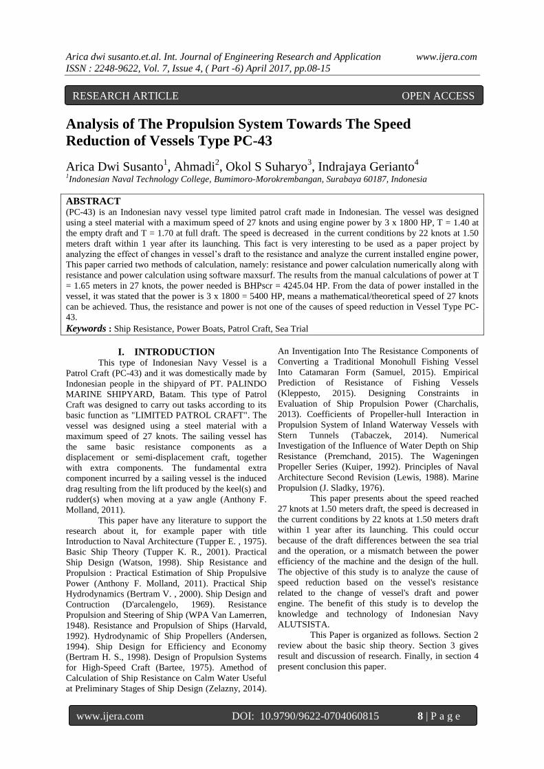
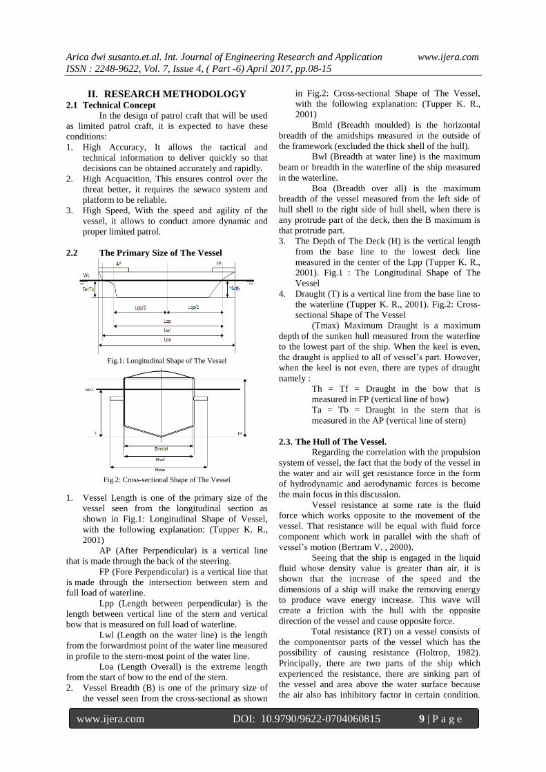
2.2 The Primary Size of The Vessel
Fig.1: Longitudinal Shape of The Vessel
Fig.2: Cross-sectional Shape of The Vessel
1. Vessel Length is one of the primary size of the
vessel seen from the longitudinal section as
shown in Fig.1: Longitudinal Shape of Vessel,
with the following explanation: (Tupper K. R.,
2001)
AP (After Perpendicular) is a vertical line
that is made through the back of the steering.
FP (Fore Perpendicular) is a vertical line that
is made through the intersection between stem and
full load of waterline.
Lpp (Length between perpendicular) is the
length between vertical line of the stern and vertical
bow that is measured on full load of waterline.
Lwl (Length on the water line) is the length
from the forwardmost point of the water line measured
in profile to the stern-most point of the water line.
Loa (Length Overall) is the extreme length
from the start of bow to the end of the stern.
2. Vessel Breadth (B) is one of the primary size of
the vessel seen from the cross-sectional as shown
in Fig.2: Cross-sectional Shape of The Vessel,
with the following explanation: (Tupper K. R.,
2001)
Bmld (Breadth moulded) is the horizontal
breadth of the amidships measured in the outside of
the framework (excluded the thick shell of the hull).
Bwl (Breadth at water line) is the maximum
beam or breadth in the waterline of the ship measured
in the waterline.
Boa (Breadth over all) is the maximum
breadth of the vessel measured from the left side of
hull shell to the right side of hull shell, when there is
any protrude part of the deck, then the B maximum is
that protrude part.
3. The Depth of The Deck (H) is the vertical length
from the base line to the lowest deck line
measured in the center of the Lpp (Tupper K. R.,
2001). Fig.1 : The Longitudinal Shape of The
Vessel
4. Draught (T) is a vertical line from the base line to
the waterline (Tupper K. R., 2001). Fig.2: Cross-
sectional Shape of The Vessel
(Tmax) Maximum Draught is a maximum
depth of the sunken hull measured from the waterline
to the lowest part of the ship. When the keel is even,
the draught is applied to all of vessel’s part. However,
when the keel is not even, there are types of draught
namely :
Th = Tf = Draught in the bow that is
measured in FP (vertical line of bow)
Ta = Tb = Draught in the stern that is
measured in the AP (vertical line of stern)
2.3. The Hull of The Vessel.
Regarding the correlation with the propulsion
system of vessel, the fact that the body of the vessel in
the water and air will get resistance force in the form
of hydrodynamic and aerodynamic forces is become
the main focus in this discussion.
Vessel resistance at some rate is the fluid
force which works opposite to the movement of the
vessel. That resistance will be equal with fluid force
component which work in parallel with the shaft of
vessel’s motion (Bertram V. , 2000).
Seeing that the ship is engaged in the liquid
fluid whose density value is greater than air, it is
shown that the increase of the speed and the
dimensions of a ship will make the removing energy
to produce wave energy increase. This wave will
create a friction with the hull with the opposite
direction of the vessel and cause opposite force.
Total resistance (RT) on a vessel consists of
the componentsor parts of the vessel which has the
possibility of causing resistance (Holtrop, 1982).
Principally, there are two parts of the ship which
experienced the resistance, there are sinking part of
the vessel and area above the water surface because
the air also has inhibitory factor in certain condition.
Arica dwi susanto.et.al. Int. Journal of Engineering Research and Application www.ijera.com
ISSN : 2248-9622, Vol. 7, Issue 4, ( Part -6) April 2017, pp.08-15
www.ijera.com DOI: 10.9790/9622-0704060815 10 | P a g e
(RT) is used to determine the Efective Horse Power
(EHP), which is defined as the power required to
actuate a vessel at the speed of (VS) and able to
overcome the resistance of (RT) and more
importantly, (EHP) is used to know the amount of
main power engine in order to avoid the surplus power
and the unfulfilled power due to the power which
can’t overcome the vessel resistance.
Total resistance (RT) of the vessel consists of
different components of resistance caused by an
interactive variety of causes. Review of the total
resistance is practically needed to deal with this
resistance in practice also it can be explained into
several main components as follows:
1. Resistance Friction occurs due to the friction
between wet surface of the vessel and media
path. Friction occurs because all of the fluid
has a viscosity value. The resistance
components are obtained by integrating the
tangential tension throughout the wet surface
of the vessel in the direction of motion of the
vessel. The components of this resistance is
shown below (Harvald, 1992):
Rf=0,5.Cf.ρ.V².S(kN) (1)
Rn=Vs.Lwl/υ (2)
Cf=0,075/(Log10Rn-2)² (3)
2. Residual Resistance (RR) is the quantity as
the result of total resistance reduction of the
hull, also known as frictional resistance as
the result of the calculation obtained by using
a special formula. In general, the maximum
part of remain resistance of the vessel is
wave making resistance. The formula is
shown below (Harvald, 1992) :
RR=(0,5xρxΔ⅔xV²) (4)
Remain resistance has coefficient value
which is obtained from ratio figures of length
and volume which are the correlation
between Froude number and elongated
prismatic coefficient.
Fn=V/√𝒈.𝑳 (5)
3. Viscous Resistance is component of the
resistance related to energy released caused
by viscous (Tupper K. R., 2001).
4. Pressure Resistance (PR) is component of
resistance which is obtained by integrated the
normal tension to all of the vessel’s surface
according to the direction of the vessel’s
motion (Tupper K. R., 2001).
5. Viscous Pressure Resistance (RPV) is
component of the resistance which is
obtained by integrated normal tension caused
by viscous and turbulence. This quantity
can’t be calculated directly except for
completely sinking object, in this case is
equal to pressure resistance (Tupper K. R.,
2001).
6. Wave making Resistance (RW) is component
of resistance which is related to energy
released to create gravitation wave
(Wehausen, 1971).
7. Wave Pattern Resistance (RWP) is
component of resistance which is concluded
from the calculation of wave elevation far
from vessel model, in this case is the
subsurface velocity field. It means the fluid
momentum can be assumed to relate to wave
pattern using linear theory. The resistance is
not included to the wave breaking resistance
(Wehausen, 1971).
8. Wave Breaking Resistance (WBR) is
component of resistance which is related to
wave breaking in the vessel’s stern
(Wehausen, 1971).
9. Spray Resistance is component of the
resistance which is related to energy released
to create spray (Harvald, 1992).
10. Appendage Resistance is resistance from the
shaft boss, shaft bracket and shaft, bilge keel
etc. In using physical models, these models
are generally equipped with parts and
included in the measurement of resistance.
Bilge keel is generally not installed. When
the parts is not included, the resistance is
called bare resistance (Harvald, 1992).
11. Roughness Resistance is resistance caused by
the roughness of the hull surface from
corrosion and fouling in the hull (Harvald,
1992).
12. Air Resistance is resistance in the water
surface and the superstructure caused by
vessel’s motion in the air flow (Harvald,
1992).
13. Steering Resistance is resistance caused by
the steering. The motion of the steering is
directed to the straightening of the path or
vessel maneuver (Harvald, 1992).
2.4. Displacement
Displacement is the weight of liquid
displaced by the hull under the water surface. When
the vessel floats in the balance state/motionless then
the downward pressure equal to the pressure of the
liquid to the hull. Thus the overall weight of the vessel
and its contents at that time equal to the weight of
liquid displaced by the hull immersed in a liquid in
Arica dwi susanto.et.al. Int. Journal of Engineering Research and Application www.ijera.com
ISSN : 2248-9622, Vol. 7, Issue 4, ( Part -6) April 2017, pp.08-15
www.ijera.com DOI: 10.9790/9622-0704060815 11 | P a g e
which the vessel is located (Anthony F. Molland,
2011).
Displacement : Lwl x B x T x CB x density of sea
water (ton)
2.5. Volume Displacement
The volume of liquid displaced by the hull
under the surfacewater where the ship is located
(Anthony F. Molland, 2011).
Volume displacement: LWL x B x T x CB
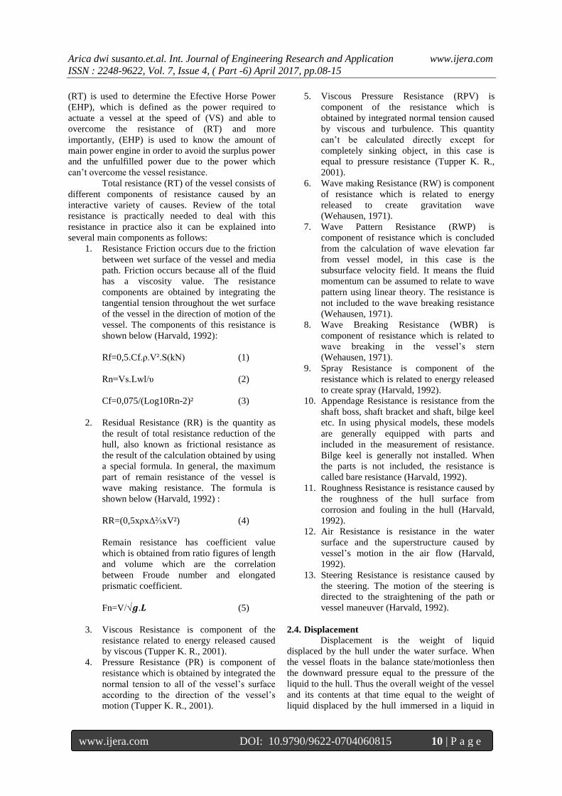
2.6. Selection of The Main Engine
In the selection of the main engine, it is
necessary to calculate the need of power engine. There
are several indicators that need to be sought in order to
obtain the desired results, those are effective horse
power (EHP), thrust horse power (THP), delivery
horse power (DHP), shaft horse power (SHP) dan
brake horse power (BHP) (Anthony F. Molland,
2011).
Fig.3: Propulsion System of The Vessel
1. Effective Horse Power (EHP) Is power
needed to actuate the vessel in water (without)
the presence of wave or to pull the vessel
with this equation below (Harvald, 1992) :
EHP = RT x Vs
2. Thrust Horse Power (THP) Is power
distributed by the vessel’s propeller without
influence of the weather or environment
condition (Lewis, 1988).
(6)
(7)
(8)
(9)
3. Delivery Horse Power (DHP) Is power
distributed to propeller, with a bracket
mechanical adverse and its propeller (Lewis,
1988).
(10)
(11)
4. Shaft Horse Power (SHP) Is power
distributed by the actuator engine (shaft
power) (Lewis, 1988).
(12)
5. Brake Horse Power (BHP) Is used for the
brake power or indicated power or power
released by by the machine with the influence
of the engine load (Lewis, 1988).
(13)
The BHP above is the power released in
normal sailing or SCR or which is
85% of the power released in maximum
condition or MCR. The power released in the
maximum condition or MCR from the main
actuator engine is explained below:
(14)
2.7. Propeller
The vessel's speed can be achieved due to the
power of vessel’s propulsion. Currently, the most
commonly used is the screw propeller. This propeller
changes the engine torque into thrust power that will
move the fluid around it. Propeller is generally
mounted on a shaft which is located at the stern of the
ship. Propeller usually works by rotating and it
produces a flow velocity which is shaped like a screw,
therefore it is known as Screw Propeller. The screw
type of propulsor has been classified into two types:
Fixed Pitch Propeller (FPP) and Controllable Pitch
Propeller (CPP) (Andersen, 1994).
Screw propeller is the most common form of
vessel’s actuator. The number of blades in the screw
propeller is ranging from three to six blades and the
position is protrude from the propeller hub. The
propeller’s blades is the part that can be merged with a
hub or can be removed and mounted on the hub like
the type of propulsion system named Controllable
picth Propeller. Propeller is generally placed in a low
position at the rear of the ship. Propeller must have a
designed diameter to accommodate the vessel to avoid
air drawing phenomenon and propulsive force
produced by propeller when the vessel moves in
pitching state by making the propeller sufficiently in
sinking condition at a full load or not-full load
condition. Screw propeller is divided into two
Arica dwi susanto.et.al. Int. Journal of Engineering Research and Application www.ijera.com
ISSN : 2248-9622, Vol. 7, Issue 4, ( Part -6) April 2017, pp.08-15
www.ijera.com DOI: 10.9790/9622-0704060815 12 | P a g e
categories: Conventional and Unconventional
Propeller (Bartee, 1975).
2.8. Hullspeed-Maxsurf
Hullspeed is a program to test resistance and
power of the model. The test results are shown in the
form of numbers and graphs.The graphs do not present
only the total of resistance and power but also the
coefficients of the resistance such as coefficient of
total resistance (CT), coefficient of wave resistance
(Cw), coefficient of remain resistance (CR) ,
coefficient of friction resistance (CF) and coefficient
of viscous resistance (Cv).
In addition to that, the program also can
determine the amount of the maximum speed and
magnitude of the efficiency. There are several
resistance methods used for testing such as Savitsky
pre-planing, Savitsky planing, Latiharju, Holtrop, van
Oortmerssent, Series 60, Delft, I, II, III and Slender
Body (Hamdani, 2012)
Each method can be used only for certain
vessels in accordance with the type. It is because each
vessels possessed different characteristics. Below is
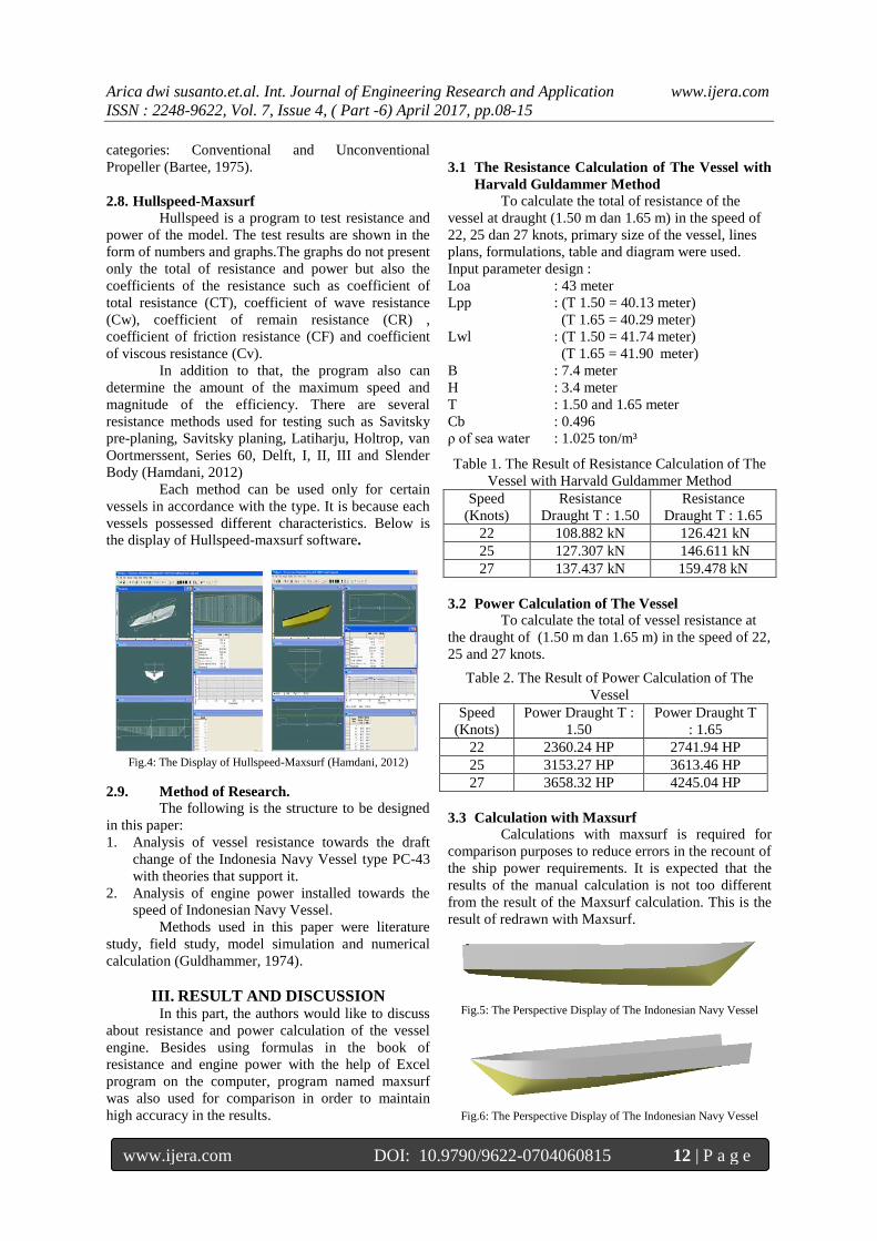
the display of Hullspeed-maxsurf software.
Fig.4: The Display of Hullspeed-Maxsurf (Hamdani, 2012)
2.9. Method of Research.
The following is the structure to be designed
in this paper:
1. Analysis of vessel resistance towards the draft
change of the Indonesia Navy Vessel type PC-43
with theories that support it.
2. Analysis of engine power installed towards the
speed of Indonesian Navy Vessel.
Methods used in this paper were literature
study, field study, model simulation and numerical
calculation (Guldhammer, 1974).
III. RESULT AND DISCUSSION In this part, the authors would like to discuss
about resistance and power calculation of the vessel
engine. Besides using formulas in the book of
resistance and engine power with the help of Excel
program on the computer, program named maxsurf
was also used for comparison in order to maintain
high accuracy in the results.
3.1 The Resistance Calculation of The Vessel with
Harvald Guldammer Method
To calculate the total of resistance of the
vessel at draught (1.50 m dan 1.65 m) in the speed of
22, 25 dan 27 knots, primary size of the vessel, lines
plans, formulations, table and diagram were used.
Input parameter design :
Loa : 43 meter
Lpp : (T 1.50 = 40.13 meter)
(T 1.65 = 40.29 meter)
Lwl : (T 1.50 = 41.74 meter)
(T 1.65 = 41.90 meter)
B : 7.4 meter
H : 3.4 meter
T : 1.50 and 1.65 meter
Cb : 0.496
ρ of sea water : 1.025 ton/m³
Table 1. The Result of Resistance Calculation of The
Vessel with Harvald Guldammer Method
Speed
(Knots)
Resistance
Draught T : 1.50
Resistance
Draught T : 1.65
22 108.882 kN 126.421 kN
25 127.307 kN 146.611 kN
27 137.437 kN 159.478 kN
3.2 Power Calculation of The Vessel
To calculate the total of vessel resistance at
the draught of (1.50 m dan 1.65 m) in the speed of 22,
25 and 27 knots.
Table 2. The Result of Power Calculation of The
Vessel
Speed
(Knots)
Power Draught T :
1.50
Power Draught T
: 1.65
22 2360.24 HP 2741.94 HP
25 3153.27 HP 3613.46 HP
27 3658.32 HP 4245.04 HP
3.3 Calculation with Maxsurf
Calculations with maxsurf is required for
comparison purposes to reduce errors in the recount of
the ship power requirements. It is expected that the
results of the manual calculation is not too different
from the result of the Maxsurf calculation. This is the
result of redrawn with Maxsurf.
Fig.5: The Perspective Display of The Indonesian Navy Vessel
Fig.6: The Perspective Display of The Indonesian Navy Vessel
Arica dwi susanto.et.al. Int. Journal of Engineering Research and Application www.ijera.com
ISSN : 2248-9622, Vol. 7, Issue 4, ( Part -6) April 2017, pp.08-15
www.ijera.com DOI: 10.9790/9622-0704060815 13 | P a g e
Fig.7: The Body Display Plan of the Indonesian Navy Vessel
Fig.8: The Display of The Wave Surface T=1.50
Fig.9: The Display of The Wave Surface T=1.65
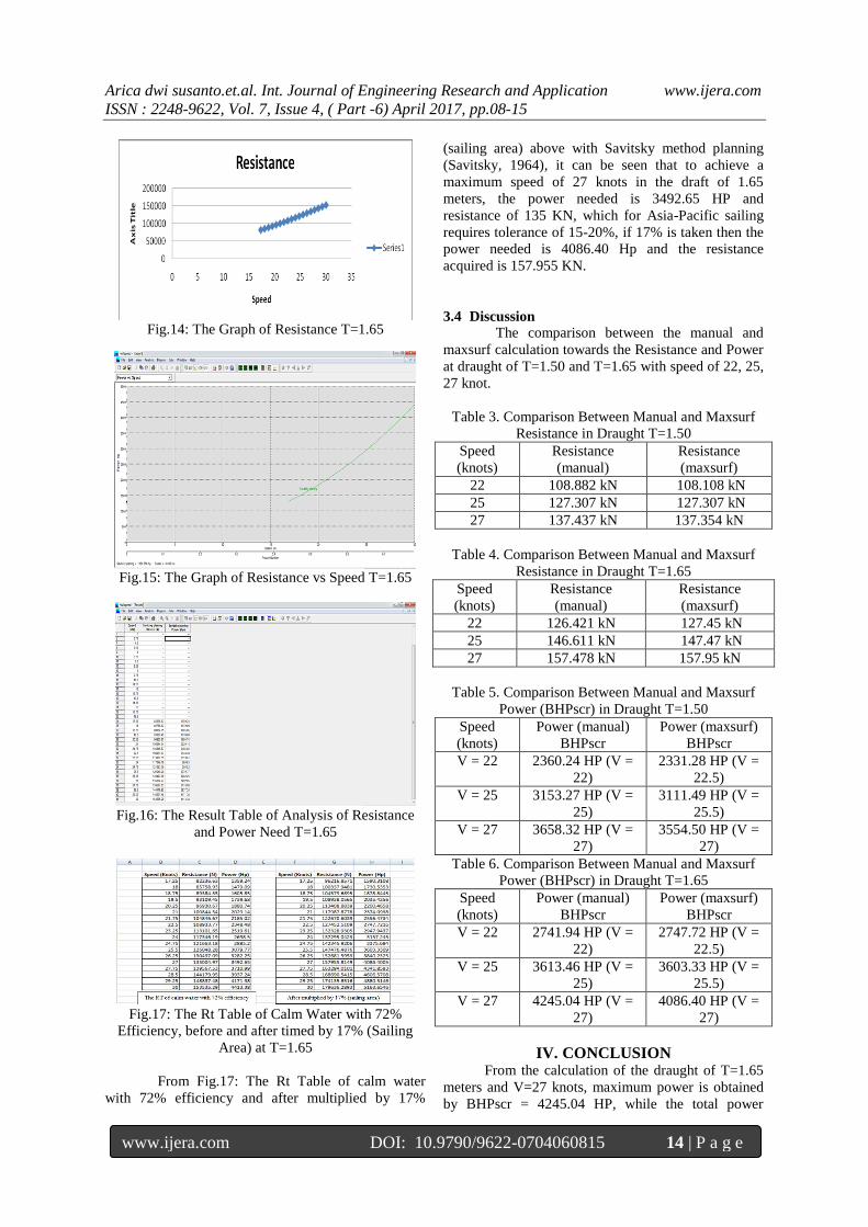
3.3.1 Result of Resistance and Power Needs
Analysis at T=1.50 Here are the results of resistance and power
needs analysis using Hullspeed with 72% efficiency at
T = 1.50 at the maxsurf:
Fig.10: The Graph of Resistance T=1.50
Fig.11: The Graph of Resistance vs Speed T=1.50
Fig.12: The Result Table of Analysis of Resistance and Power Need
T=1.50
Fig.13: The Rt Table of Calm Water with 72%
Efficiency, before and after timed by 17% (Sailing
Area) at T=1.50
From Fig.13: The Rt Table of calm water
with 72% efficiency and after multiplied by 17%
(sailing area) above with Savitsky method planning
(Savitsky, 1964), it can be seen that to achieve a
maximum speed of 27 knots in the draft of 1.50
meters, the power needed is 3038 HP and resistance of
117.4 KN, which for Asia-Pacific sailing requires
tolerance of 15-20%, if 17% is taken then the power
needed is 3554.50 Hp and the resistance acquired is
137.358 KN.
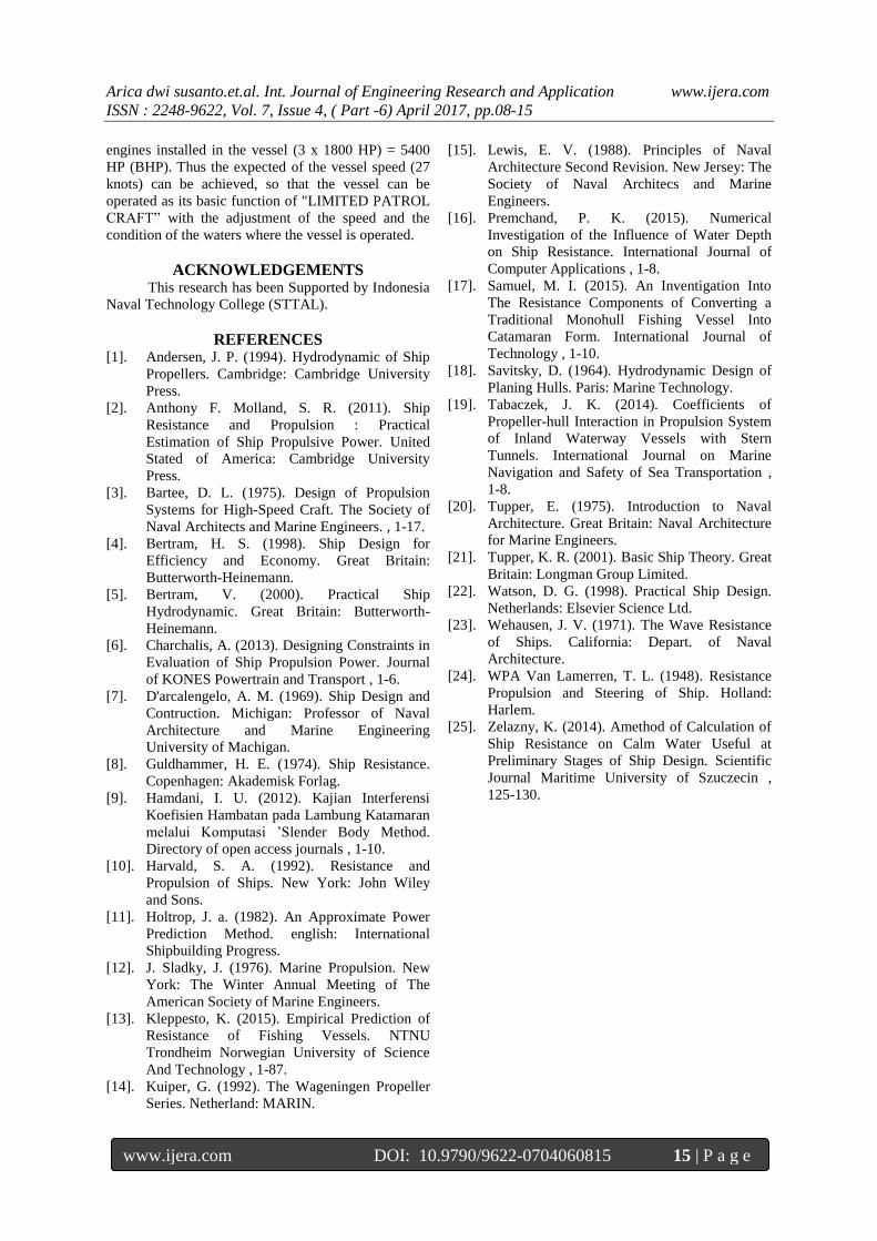
3.3.2 Result of Resistance and Power Needs
Analysis at T=1.65
Here are the results of resistance and power
needs analysis using Hullspeed with 72% efficiency at
T = 1.65 at the maxsurf:
Arica dwi susanto.et.al. Int. Journal of Engineering Research and Application www.ijera.com
ISSN : 2248-9622, Vol. 7, Issue 4, ( Part -6) April 2017, pp.08-15
www.ijera.com DOI: 10.9790/9622-0704060815 14 | P a g e
Fig.14: The Graph of Resistance T=1.65
Fig.15: The Graph of Resistance vs Speed T=1.65
Fig.16: The Result Table of Analysis of Resistance
and Power Need T=1.65
Fig.17: The Rt Table of Calm Water with 72%
Efficiency, before and after timed by 17% (Sailing
Area) at T=1.65
From Fig.17: The Rt Table of calm water
with 72% efficiency and after multiplied by 17%
(sailing area) above with Savitsky method planning
(Savitsky, 1964), it can be seen that to achieve a
maximum speed of 27 knots in the draft of 1.65
meters, the power needed is 3492.65 HP and
resistance of 135 KN, which for Asia-Pacific sailing
requires tolerance of 15-20%, if 17% is taken then the
power needed is 4086.40 Hp and the resistance
acquired is 157.955 KN.
3.4 Discussion
The comparison between the manual and
maxsurf calculation towards the Resistance and Power
at draught of T=1.50 and T=1.65 with speed of 22, 25,
27 knot.
Table 3. Comparison Between Manual and Maxsurf
Resistance in Draught T=1.50
Speed
(knots)
Resistance
(manual)
Resistance
(maxsurf)
22 108.882 kN 108.108 kN
25 127.307 kN 127.307 kN
27 137.437 kN 137.354 kN
Table 4. Comparison Between Manual and Maxsurf
Resistance in Draught T=1.65
Speed
(knots)
Resistance
(manual)
Resistance
(maxsurf)
22 126.421 kN 127.45 kN
25 146.611 kN 147.47 kN
27 157.478 kN 157.95 kN
Table 5. Comparison Between Manual and Maxsurf
Power (BHPscr) in Draught T=1.50
Speed
(knots)
Power (manual)
BHPscr
Power (maxsurf)
BHPscr
V = 22 2360.24 HP (V =
22)
2331.28 HP (V =
22.5)
V = 25 3153.27 HP (V =
25)
3111.49 HP (V =
25.5)
V = 27 3658.32 HP (V =
27)
3554.50 HP (V =
27)
Table 6. Comparison Between Manual and Maxsurf
Power (BHPscr) in Draught T=1.65
Speed
(knots)
Power (manual)
BHPscr
Power (maxsurf)
BHPscr
V = 22 2741.94 HP (V =
22)
2747.72 HP (V =
22.5)
V = 25 3613.46 HP (V =
25)
3603.33 HP (V =
25.5)
V = 27 4245.04 HP (V =
27)
4086.40 HP (V =
27)
IV. CONCLUSION
From the calculation of the draught of T=1.65
meters and V=27 knots, maximum power is obtained
by BHPscr = 4245.04 HP, while the total power
Arica dwi susanto.et.al. Int. Journal of Engineering Research and Application www.ijera.com
ISSN : 2248-9622, Vol. 7, Issue 4, ( Part -6) April 2017, pp.08-15
www.ijera.com DOI: 10.9790/9622-0704060815 15 | P a g e
engines installed in the vessel (3 x 1800 HP) = 5400
HP (BHP). Thus the expected of the vessel speed (27
knots) can be achieved, so that the vessel can be
operated as its basic function of "LIMITED PATROL
CRAFT” with the adjustment of the speed and the
condition of the waters where the vessel is operated.
ACKNOWLEDGEMENTS
This research has been Supported by Indonesia
Naval Technology College (STTAL).
REFERENCES
[1]. Andersen, J. P. (1994). Hydrodynamic of Ship
Propellers. Cambridge: Cambridge University
Press.
[2]. Anthony F. Molland, S. R. (2011). Ship
Resistance and Propulsion : Practical
Estimation of Ship Propulsive Power. United
Stated of America: Cambridge University
Press.
[3]. Bartee, D. L. (1975). Design of Propulsion
Systems for High-Speed Craft. The Society of
Naval Architects and Marine Engineers. , 1-17.
[4]. Bertram, H. S. (1998). Ship Design for
Efficiency and Economy. Great Britain:
Butterworth-Heinemann.
[5]. Bertram, V. (2000). Practical Ship
Hydrodynamic. Great Britain: Butterworth-
Heinemann.
[6]. Charchalis, A. (2013). Designing Constraints in
Evaluation of Ship Propulsion Power. Journal
of KONES Powertrain and Transport , 1-6.
[7]. D'arcalengelo, A. M. (1969). Ship Design and
Contruction. Michigan: Professor of Naval
Architecture and Marine Engineering
University of Machigan.
[8]. Guldhammer, H. E. (1974). Ship Resistance.
Copenhagen: Akademisk Forlag.
[9]. Hamdani, I. U. (2012). Kajian Interferensi
Koefisien Hambatan pada Lambung Katamaran
melalui Komputasi ’Slender Body Method.
Directory of open access journals , 1-10.
[10]. Harvald, S. A. (1992). Resistance and
Propulsion of Ships. New York: John Wiley
and Sons.
[11]. Holtrop, J. a. (1982). An Approximate Power
Prediction Method. english: International
Shipbuilding Progress.
[12]. J. Sladky, J. (1976). Marine Propulsion. New
York: The Winter Annual Meeting of The
American Society of Marine Engineers.
[13]. Kleppesto, K. (2015). Empirical Prediction of
Resistance of Fishing Vessels. NTNU
Trondheim Norwegian University of Science
And Technology , 1-87.
[14]. Kuiper, G. (1992). The Wageningen Propeller
Series. Netherland: MARIN.
[15]. Lewis, E. V. (1988). Principles of Naval
Architecture Second Revision. New Jersey: The
Society of Naval Architecs and Marine
Engineers.
[16]. Premchand, P. K. (2015). Numerical
Investigation of the Influence of Water Depth
on Ship Resistance. International Journal of
Computer Applications , 1-8.
[17]. Samuel, M. I. (2015). An Inventigation Into
The Resistance Components of Converting a
Traditional Monohull Fishing Vessel Into
Catamaran Form. International Journal of
Technology , 1-10.
[18]. Savitsky, D. (1964). Hydrodynamic Design of
Planing Hulls. Paris: Marine Technology.
[19]. Tabaczek, J. K. (2014). Coefficients of
Propeller-hull Interaction in Propulsion System
of Inland Waterway Vessels with Stern
Tunnels. International Journal on Marine
Navigation and Safety of Sea Transportation ,
1-8.
[20]. Tupper, E. (1975). Introduction to Naval
Architecture. Great Britain: Naval Architecture
for Marine Engineers.
[21]. Tupper, K. R. (2001). Basic Ship Theory. Great
Britain: Longman Group Limited.
[22]. Watson, D. G. (1998). Practical Ship Design.
Netherlands: Elsevier Science Ltd.
[23]. Wehausen, J. V. (1971). The Wave Resistance
of Ships. California: Depart. of Naval
Architecture.
[24]. WPA Van Lamerren, T. L. (1948). Resistance
Propulsion and Steering of Ship. Holland:
Harlem.
[25]. Zelazny, K. (2014). Amethod of Calculation of
Ship Resistance on Calm Water Useful at
Preliminary Stages of Ship Design. Scientific
Journal Maritime University of Szuczecin ,
125-130.