Embed Size (px)
Citation preview
ANALYSIS OF STERSSES
General State of stress at a point :
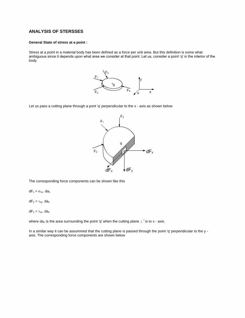
Stress at a point in a material body has been defined as a force per unit area. But this definition is some what ambiguous since it depends upon what area we consider at that point. Let us, consider a point ‘q' in the interior of the body
Let us pass a cutting plane through a pont 'q' perpendicular to the x - axis as shown below
The corresponding force components can be shown like this
dFx = xx. dax
dFy = xy. dax
dFz = xz. dax
where dax is the area surrounding the point 'q' when the cutting plane r is to x - axis.
In a similar way it can be assummed that the cutting plane is passed through the point 'q' perpendicular to the y - axis. The corresponding force components are shown below

The corresponding force components may be written as
dFx = yx. day
dFy = yy. day
dFz = yz. day
where day is the area surrounding the point 'q' when the cutting plane r is to y - axis.
In the last it can be considered that the cutting plane is passed through the point 'q' perpendicular to the z - axis.
The corresponding force components may be written as
dFx = zx. daz
dFy = zy. daz
dFz = zz. daz
where daz is the area surrounding the point 'q' when the cutting plane r is to z - axis.
Thus, from the foregoing discussion it is amply clear that there is nothing like stress at a point 'q' rather we have a situation where it is a combination of state of stress at a point q. Thus, it becomes imperative to understand the term state of stress at a point 'q'. Therefore, it becomes easy to express astate of stress by the scheme as discussed earlier, where the stresses on the three mutually perpendiclar planes are labelled in the manner as shown earlier. the state of stress as depicted earlier is called the general or a triaxial state of stress that can exist at any interior point of a loaded body.
Before defining the general state of stress at a point. Let us make overselves conversant with the notations for the stresses.
We have already chosen to distinguish between normal and shear stress with the help of symbols and .
Cartesian - co-ordinate system
In the Cartesian co-ordinates system, we make use of the axes, X, Y and Z
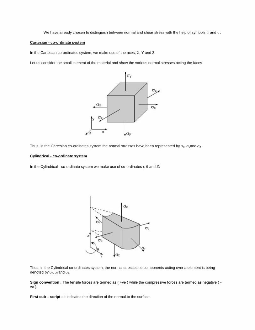
Let us consider the small element of the material and show the various normal stresses acting the faces
Thus, in the Cartesian co-ordinates system the normal stresses have been represented by x, yand z.
Cylindrical - co-ordinate system
In the Cylindrical - co-ordinate system we make use of co-ordinates r, and Z.
Thus, in the Cylindrical co-ordinates system, the normal stresses i.e components acting over a element is being
denoted by r, and z.
Sign convention : The tensile forces are termed as ( +ve ) while the compressive forces are termed as negative ( -ve ).
First sub – script : it indicates the direction of the normal to the surface.

Second subscript : it indicates the direction of the stress.
It may be noted that in the case of normal stresses the double script notation may be dispensed with as the direction of the normal stress and the direction of normal to the surface of the element on which it acts is the same. Therefore, a single subscript notation as used is sufficient to define the normal stresses.
Shear Stresses : With shear stress components, the single subscript notation is not practical, because such stresses
are in direction parallel to the surfaces on which they act. We therefore have two directions to specify, that of normal
to the surface and the stress itself. To do this, we stress itself. To do this, we attach two subscripts to the symbol ' ' , for shear stresses.
In cartesian and polar co-ordinates, we have the stress components as shown in the figures.
xy , yx , yz , zy , zx , xz
r , r , z , z ,zr , rz
So as shown above, the normal stresses and shear stress components indicated on a small element of material seperately has been combined and depicted on a single element. Similarly for a cylindrical co-ordinate system let us shown the normal and shear stresses components separately.

Now let us combine the normal and shear stress components as shown below :
Now let us define the state of stress at a point formally.
State of stress at a point :

By state of stress at a point, we mean an information which is required at that point such that it remains under equilibrium. or simply a general state of stress at a point involves all the normal stress components, together with all the shear stress components as shown in earlier figures.
Therefore, we need nine components, to define the state of stress at a point
x xy xz
y yx yz
z zx zy
If we apply the conditions of equilibrium which are as follows:
Fx = 0 ; M x = 0
Fy = 0 ; M y = 0
Fz = 0 ; M z = 0
Then we get
xy = yx
yz = zy
zx = xy
Then we will need only six components to specify the state of stress at a point i.e
x , y, z , xy , yz , zx
Now let us define the concept of complementary shear stresses.
Complementary shear stresses:
The existence of shear stresses on any two sides of the element induces complementary shear stresses on the other two sides of the element to maintain equilibrium.
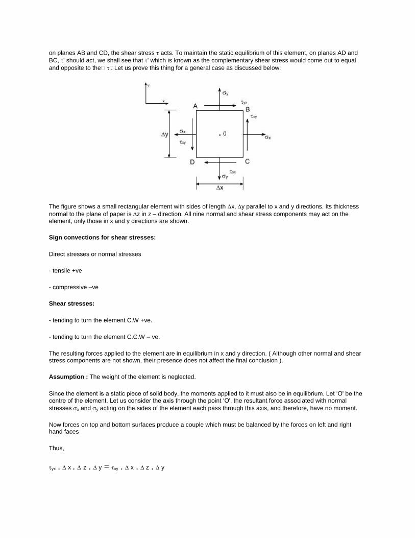
on planes AB and CD, the shear stress acts. To maintain the static equilibrium of this element, on planes AD and
BC, ' should act, we shall see that ' which is known as the complementary shear stress would come out to equal
and opposite to the. Let us prove this thing for a general case as discussed below:
The figure shows a small rectangular element with sides of length x, y parallel to x and y directions. Its thickness
normal to the plane of paper is z in z – direction. All nine normal and shear stress components may act on the element, only those in x and y directions are shown.
Sign convections for shear stresses:
Direct stresses or normal stresses
- tensile +ve
- compressive –ve
Shear stresses:
- tending to turn the element C.W +ve.
- tending to turn the element C.C.W – ve.
The resulting forces applied to the element are in equilibrium in x and y direction. ( Although other normal and shear stress components are not shown, their presence does not affect the final conclusion ).
Assumption : The weight of the element is neglected.
Since the element is a static piece of solid body, the moments applied to it must also be in equilibrium. Let ‘O' be the centre of the element. Let us consider the axis through the point ‘O'. the resultant force associated with normal
stresses x and y acting on the sides of the element each pass through this axis, and therefore, have no moment.
Now forces on top and bottom surfaces produce a couple which must be balanced by the forces on left and right hand faces
Thus,
yx . x . z . y = xy . x . z . y

In other word, the complementary shear stresses are equal in magnitude. The same form of relationship can be obtained for the other two pair of shear stress components to arrive at the relations
Analysis of Stresses:
Consider a point ‘q' in some sort of structural member like as shown in figure below. Assuming that at point exist. ‘q' a
plane state of stress exist. i.e. the state of state stress is to describe by a parameters x, yand xy These stresses could be indicate a on the two dimensional diagram as shown below:
This is a commen way of representing the stresses. It must be realize a that the material is unaware of what we have called the x and y axes. i.e. the material has to resist the loads irrespective less of how we wish to name them or whether they are horizontal, vertical or otherwise further more, the material will fail when the stresses exceed beyond a permissible value. Thus, a fundamental problem in engineering design is to determine the maximum normal stress
or maximum shear stress at any particular point in a body. There is no reason to believe apriori that x, y and xy are
the maximum value. Rather the maximum stresses may associates themselves with some other planes located at ‘'.
Thus, it becomes imperative to determine the values of and. In order tto achieve this let us consider the following.
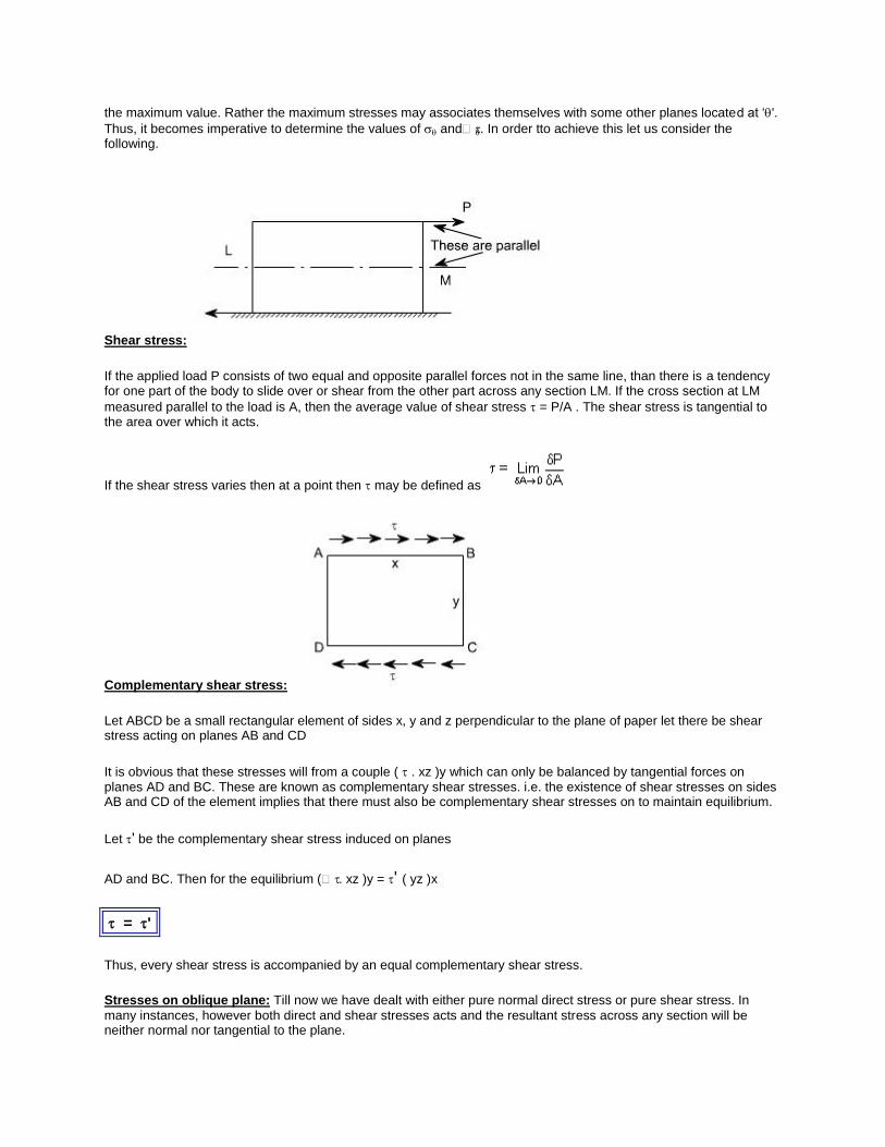
Shear stress:
If the applied load P consists of two equal and opposite parallel forces not in the same line, than there is a tendency for one part of the body to slide over or shear from the other part across any section LM. If the cross section at LM
measured parallel to the load is A, then the average value of shear stress = P/A . The shear stress is tangential to the area over which it acts.
If the shear stress varies then at a point then may be defined as
Complementary shear stress:
Let ABCD be a small rectangular element of sides x, y and z perpendicular to the plane of paper let there be shear stress acting on planes AB and CD
It is obvious that these stresses will from a couple ( . xz )y which can only be balanced by tangential forces on planes AD and BC. These are known as complementary shear stresses. i.e. the existence of shear stresses on sides AB and CD of the element implies that there must also be complementary shear stresses on to maintain equilibrium.
Let ' be the complementary shear stress induced on planes
AD and BC. Then for the equilibrium ( . xz )y = ' ( yz )x
= '
Thus, every shear stress is accompanied by an equal complementary shear stress.
Stresses on oblique plane: Till now we have dealt with either pure normal direct stress or pure shear stress. In
many instances, however both direct and shear stresses acts and the resultant stress across any section will be neither normal nor tangential to the plane.

A plane stse of stress is a 2 dimensional stae of stress in a sense that the stress components in one direction are all zero i.e
z = yz = zx = 0
examples of plane state of stress includes plates and shells.
Consider the general case of a bar under direct load F giving rise to a stress y vertically
The stress acting at a point is represented by the stresses acting on the faces of the element enclosing the point.
The stresses change with the inclination of the planes passing through that point i.e. the stress on the faces of the element vary as the angular position of the element changes.
Let the block be of unit depth now considering the equilibrium of forces on the triangle portion ABC
Resolving forces perpendicular to BC, gives
.BC.1 = ysin . AB . 1
but AB/BC = sin or AB = BCsin
Substituting this value in the above equation, we get
.BC.1 = ysin . BCsin . 1 or (1)
Now resolving the forces parallel to BC
.BC.1 = y cos . ABsin . 1
again AB = BCcos
.BC.1 = ycos . BCsin . 1 or = ysincos

(2)
If = 900 the BC will be parallel to AB and = 0, i.e. there will be only direct stress or normal stress.
By examining the equations (1) and (2), the following conclusions may be drawn
(i) The value of direct stress is maximum and is equal to y when = 900.
(ii) The shear stress has a maximum value of 0.5 y when = 450
(iii) The stresses and are not simply the resolution of y
Material subjected to pure shear:
Consider the element shown to which shear stresses have been applied to the sides AB and DC
Complementary shear stresses of equal value but of opposite effect are then set up on the sides AD and BC in order to prevent the rotation of the element. Since the applied and complementary shear stresses are of equal value on the
x and y planes. Therefore, they are both represented by the symbol xy.
Now consider the equilibrium of portion of PBC
Assuming unit depth and resolving normal to PC or in the direction of
.PC.1 =xy.PB.cos.1+xy.BC.sin.1
= xy.PB.cos + xy.BC.sin
Now writing PB and BC in terms of PC so that it cancels out from the two sides
PB/PC = sin BC/PC = cos
.PC.1 = xy.cossinPC+ xy.cos.sinPC
= 2xysincos
= xy.2.sincos
(1)
Now resolving forces parallel to PC or in the direction .then xyPC . 1 =xy . PBsin xy . BCcos
ve sign has been put because this component is in the same direction as that of .
again converting the various quantities in terms of PC we have
xyPC . 1 =xy . PB.sin2 xy . PCcos
2
= [xy (cos2 sin
2) ]
= xycos2or (2)
the negative sign means that the sense of is opposite to that of assumed one. Let us examine the equations (1) and (2) respectively
From equation (1) i.e,
= xy sin2
The equation (1) represents that the maximum value of isxy when = 450.
Let us take into consideration the equation (2) which states that
=xy cos2
It indicates that the maximum value of isxy when = 00 or 90
0. it has a value zero when = 45
0.
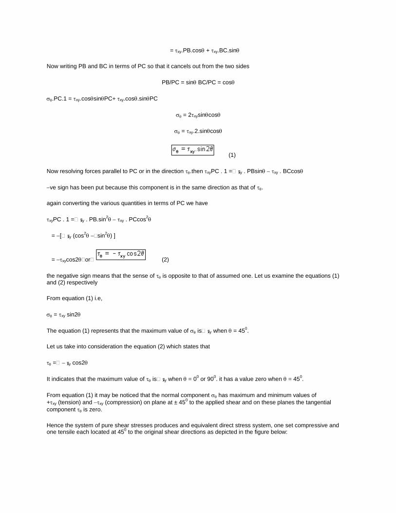
From equation (1) it may be noticed that the normal component has maximum and minimum values of
+xy (tension) and xy (compression) on plane at ± 450 to the applied shear and on these planes the tangential
component is zero.
Hence the system of pure shear stresses produces and equivalent direct stress system, one set compressive and one tensile each located at 45
0 to the original shear directions as depicted in the figure below:
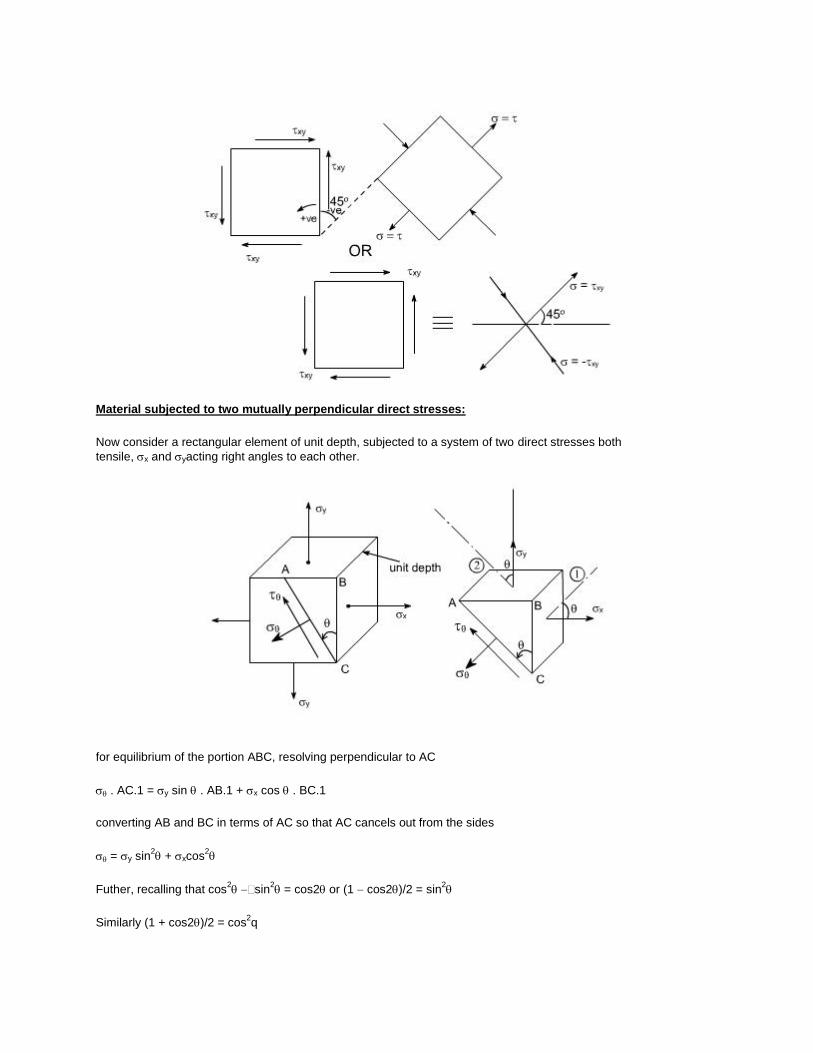
Material subjected to two mutually perpendicular direct stresses:
Now consider a rectangular element of unit depth, subjected to a system of two direct stresses both
tensile, x and yacting right angles to each other.
for equilibrium of the portion ABC, resolving perpendicular to AC
. AC.1 = y sin . AB.1 + x cos . BC.1
converting AB and BC in terms of AC so that AC cancels out from the sides
= y sin2 + xcos
2
Futher, recalling that cos2 sin
2 = cos2 or (1 cos2)/2 = sin
2
Similarly (1 + cos2)/2 = cos2q

Hence by these transformations the expression for reduces to
= 1/2y (1 cos2) + 1/2x (1 + cos2)
On rearranging the various terms we get
(3)
Now resolving parallal to AC
sq.AC.1= xy..cos.AB.1+xy.BC.sin.1
The – ve sign appears because this component is in the same direction as that of AC.
Again converting the various quantities in terms of AC so that the AC cancels out from the two sides.
(4)
Conclusions :
The following conclusions may be drawn from equation (3) and (4)
(i) The maximum direct stress would be equal to x or y which ever is the greater, when = 00 or 90
0
(ii) The maximum shear stress in the plane of the applied stresses occurs when = 450
Source: http://nptel.ac.in/courses/Webcourse-contents/IIT-
ROORKEE/strength%20of%20materials/homepage.htm