Embed Size (px)
Citation preview

(IJACSA) International Journal of Advanced Computer Science and Applications,
Vol. 8, No. 7, 2017
164 | P a g e
www.ijacsa.thesai.org
Analysis of Received Power Characteristics of
Commercial Photodiodes in Indoor Los Channel
Visible Light Communication
Syifaul Fuada1, Angga Pratama Putra
2, Trio Adiono
3
1,2,3 University Center of Excellence on Microelectronics, Institut Teknologi Bandung
PAU Building 4th
floor, Tamansari street No.126, Bandung city, West Java, ZIP 40132
INDONESIA
Abstract—To date, the photodiode still the first choice
component is used in optical communication, especially for
visible light communication (VLC) system. It has advantages of
speed, energy consumption, and sensitivity, compared to other
devices (e.g. image sensor). There are many practical
implementations of high-speed VLC which uses photodiode.
Commercially available photodiode typically have specific
characteristics, so that it needs some consideration to be used as
optimal receiver devices in VLC system. In this paper, analysis of
received power characteristics of the photodiode in indoor line-
of-sight (LoS) channel of VLC system is discussed. MATLAB®
simulation is used as approach model (student version). The
experiments are done by changing several parameters such as the
semi-angle half power of the transmitter, distance from the
transmitter to receiver, room size, field-of-view (FOV), lens index
and optical filter gain. From the results, it can be known that
distance, room size, FOV and LED power factor to have linear
characteristic against the received power of commercial
photodiode. Also in LoS channel model, the gain of optical filter
and lens index plays an important role in defining the
characteristics of received power.
Keywords—Commercial photodiodes; LoS channel; power
received; visible light communication
I. INTRODUCTION
In recent decades, many researchers are interested in research of Visible Light Communication (VLC) for various application, such as vehicle to vehicle communication, Light Fidelity (Li-Fi), hospitals data communication, real-time audio & video transmission, underwater communication, space communication, localization based movable devices (mobile robot or autonomous robot), WLANs, visible light ID system and so on.
There are many research about comparative study in VLC system that is interesting to be discussed to gain deeper understanding to develop VLC system, such as different modulation technique in VLC system [1], comparison study of OFDM multiplexing schemes (DCO, ACO, ADO) [2], placement optimization of LED-array as emitter [3], available bandwidth through red, green and blue phosphor LED [4], effect of color filter in VLC physical layer system using mica paper [5]-[6], noise analysis using variety Op-Amp and photodiode for VLC system [7]-[8], single versus multicarrier performance analysis [9], performance comparison using
variety QAM modulation from 4 to 512 based RGB LED [10], analysis of different LED array spacing [11], VLC system performance within and without analog filters [12], decoder performance within and without Viterbi [13], and so on.
Photodiode is a common photodetector device that can be used for precision measurement or optical communication application, e.g. VLC, fiber optic and infrared communication. Compared with other devices, such as the light dependent resistor (LDR), photo-IC, solar cell and phototransistor, The photodiode has several advantages in stability, precision and response time. The commercial photodiode can be divided into several types, those are: 1) precision photodiode that can be properly used for light measurement; 2) high-speed photodiode that has general characteristic of high cut-off frequency, which is suitable for optical application; or 3) integrated photodiode such as S8475 and S9295, manufactured by HAMAMATSU®, which already integrated with pre-amp in a single chip. Each type of photodiode has its own advantages and disadvantages.
There are various studies about the comparison of photodiode types for application of optical communication. The photodiode selection is important in communication system because it can affect sensitivity, speed, range, reliability, cost, and another factor in the communication system. Research scheme of photodiode types already been done by A. Boudkhil, et al. [14] who compares noise performances of PIN and APD photodiodes through an optical high debit transmission chain. Then P. Sharma, et al [15] compares PIN and APD performances with different modulation and wavelength of LED transmitter. Also M.A.A Ali [16] analyze APD performances for underwater communication application through combination scheme of the Jerlov water variable types (I, IA, IB) and photodiode material types (Si, Ge, InGaAs). Then O. Kharraz and D. Forsyth [17] analyze optical excess noise and thermal noise which exist in PIN and APD. Then Y. Chen, et al [18] experiment about optimizing collimating lens of the photodetector for supporting long range VLC. The author himself already done the investigation on capacitor junction (Cj) effect on total noise, which is an RMS function of voltage noise, current noise and feedback resistor in discrete TIA circuit [19]. All of the above six experiments are done through analytical calculus approach and proven by MATLAB® and other specific simulator tools.

(IJACSA) International Journal of Advanced Computer Science and Applications,
Vol. 8, No. 7, 2017
165 | P a g e
www.ijacsa.thesai.org
The VLC system can be divided into three main parts, transmitter, channel and receiver. Channel in VLC system is a free space which can be implemented as Line-of-Sight (LoS) and Non-Line-of-Sight (NLoS) link. In LoS, one of its weak points is on shadowing effect which is caused by object blocking, such as by household equipment or human activities. Another LoS weak point is its limited covering area capability, so it's incapable of supporting mobile user because the LoS configuration requires transmitter and receiver to be placed in a straight line. The solution of this problem is by using photodiode which has broad FOV characteristic. Besides that, the LoS advantage is on its characteristic that can support high-speed data transfer for a relatively long distance and its invulnerability of distortion from multipath signal induction and ambient light noise. Illustration of the LoS link is shown in Fig. 1(a), in which photodiode as receiver placed on a straight line from LED. This link angular distribution is shown in Fig. 1(b). The mathematical derivation of the LoS link is explained in Section III of this paper.
The light information which transmitted from the LED will be weakened (fading) while transmitted on the free space channel, it means the farther the distance of the receiver, the weaker the signal received, and the information may not be received at all [20]. For that problem, the solution is to increase the LED power or to add more LED as the transmitter. But this is not the best solutions because it is not power efficient. Besides, adding more LED will add another problem, roaming. The ideal solution is by selecting the proper photodiode and optimizing the photodiode filter.
The ideal photodiode characteristics can be found in the datasheet from each manufacturer, where its specification can be analyzed through finding the relations of LED power of the VLC system with the received power in the photodiode (see Section III). By using this method, we can accurately predict the performance of the photodiode which will be implemented in VLC system. Based on the observations from many works of literature until this far, the discussion about photodiode‟s received power characteristic of the different commercially available photodiode is still rarely found. Related research has
been discussed by K. Lee, et al. [21] which analyzes the effect of photodiode‟s received power with LoS and NLoS scenarios with different wall type. Since this paper isn‟t exploring the received power characteristic based on different photodiode manufacturer, on this paper we will discuss that characteristic of the photodiode based on different manufacturer. The motivation of writing this paper is to fill that area of study.
Besides that, we also done other experiments that observing the effect of changing several parameters of the LoS channel against the received power on the photodiode, such as 1) changing semi-angle of the transmitter; 2) variating power of a single LED; and 3) changing the distances of the channel. After that, the effect of FOV, room dimension and internal concentrator of the photodiode against its received power characteristic will also be investigated. To find the ideal value of this characteristics, these experiments using simulation based approach using MATLAB® have been performed.
This paper is divided into several parts. The first part is an overview of VLC system, research area, channel system, problems and purpose of the experiments. The second part explained the photodiode consideration and several types of the photodiode. The third part explained the detail of the LoS channel which has been introduced in the introduction part. The fourth part discusses the experiment set-up, results, and analysis. And the last part consisted of conclusion, acknowledgment, and references.
II. PHOTODIODE CONSIDERATIONS IN VLC SYSTEMS
Several considerations on selecting commercial photodiode for VLC application is as follows: 1) surface area; 2) generated short current; 3) capabilities to detect wavelength; 4) frequency cut-off; 5) rise-time; and 6) dark current and internal capacitance/junction capacitor (Cj).
With broad surface area, for example, 10 mm x 10 mm, the photodiodes can be used to support mobility in VLC system. This sensing area capability can be improved by arranging the photodiode in an array setup such as being done by J.H. Li, et al. [22].
(a) (b)
Fig. 1. (a) Geometry of LoS channel configuration in 3 m x 3 m x 3 m room; (b) MATLAB® simulation of light intensity distribution in room using LED with
characteristics of 30 Watt, d = 1 meter, FOV = 30o, number of transmitter = 1, number of grid = 25, = , and =
(IJACSA) International Journal of Advanced Computer Science and Applications,
Vol. 8, No. 7, 2017
166 | P a g e
www.ijacsa.thesai.org
Although, the larger the area, the cut-off frequency will become narrower and tend to be easily disturbed by the ambient light noise. For the high-speed application, this characteristic needs to be considered, to make the robust VLC system design that has high tolerances characteristic with noise from other light sources, such as sunlight.
After that, we also need to consider the short current. As we all know, the photodiode will generate current with linear characteristic against the light intensity, the brighter the light intensity, the higher the current that will be generated, at least around >100µA. The lower the short current, the higher the gain of the Op-Amp, and it will affect on the narrower bandwidth. The cut-off frequency (f-3dB) is inversely proportionated with the division of Op-Amp Gain Bandwidth Product (GBW) and voltage gain (Av). Another factor that needs to be considered is the wavelengths that can still be detected. On VLC application, the chosen the photodiode needs to has capabilities to senses wavelength in visible light spectrum range, i.e. 380 nm to 780 nm. Mistakes on the selection of the phtodiode can affect the system to not be able to work optimally.
A photodiode with high cut-off frequency (~GHz scale) and fast rise time (~nanosecond scale) characteristics can be used for high-speed optical communication, although typically these characteristics have to trade off with the narrow sensing area (around 0.1 mm), so while it supports high-speed data transfer, it doesn‟t support the mobility of VLC system, and the receiver needs to have 0
° elevation angle. Even though, in
general, the VLC needs to able to provides mobility characteristic. This problem has several solutions such as using optic concentrator (collimator lens or polarizer) to focusing the light into the photodiode, adding more information light sources (for example, array LED based inter-cell system) or arranging the photodiode in an array based setup.
The dark current is generated current from a photodiode in a dark condition (no-light). The chosen PD needs to have low dark current characteristic and also low the Cj. In previous research, the lower the Cj, the higher the noise on the photodiode and the slower the response of photodiode amplifier. Both of these characteristics are important, and it will affect noise on the photodiode which have strong relations with en and in on the chosen Op- Amp [23].
All of those six factors above, can‟t be obtained simultaneously. Commercially available photodiode, typically only have one or two of those characteristics (no more than three), thus the selection process must be thorough. These limitations can be used as main consideration to create self-made photodiode in a research based method, as been done by H. Chen, et al. [24] and W. Zou, et al. [25].
In VLC practical demonstration, there are two types of the photodiode that are of primary interest, i.e. Positive-Intrinsic-Negative (PIN) and Avalanche photodiode (APD). The characteristics of both of these photodiodes has been discussed by M. Azadeh [26]. The comparison of PIN and APD is shown in Table 1. These data are gathered from many work of literature. To make it short, PIN provides higher sensitivity, higher bandwidth, lower operating voltage and also cheaper.
TABLE I. COMPARISON BETWEEN PIN AND APD IN VLC SYSTEM
Variable PIN APD
Materials Si, Ge, InGaAs
Bandwidth To 40 GHz
Life time OK
Spectral range Tunable (Ultraviolet, Visible light, Near
Infra-red)
Form factor Small
Electromagnetic immunity No
Magnetic field sensitivity No
Large area No
Gain 1 102
Operating Voltage (V) Low
(0 - 5)
High
(100 -100k)
Cost Low High
Efficiency (A/W) Low High
Response time Fast Slow
Sensing sensitivity Low High
Temperature sensitivity Low High
Bandwidth & bit rate High Medium
Damage by Stray light No Yes
Dark current High Low
Excess noise factor Low Medium
Mechanical Robustness High Medium
III. THE LOS CHANNELS DESCRIPTION
. As shown in Fig. 1(a), LED placed at height h relative at region „x‟ and „y‟ from the receiver. LED radiation angle of the transmitter to the receiver against transmitter normal, denoted with . Whereas LED radiation angle to the receiver against receiver normal, denoted with , where the receiver has a FOV. LED radiation can only be sensed while on the FOV range, where maximum angle range against the receiver normal denoted with .
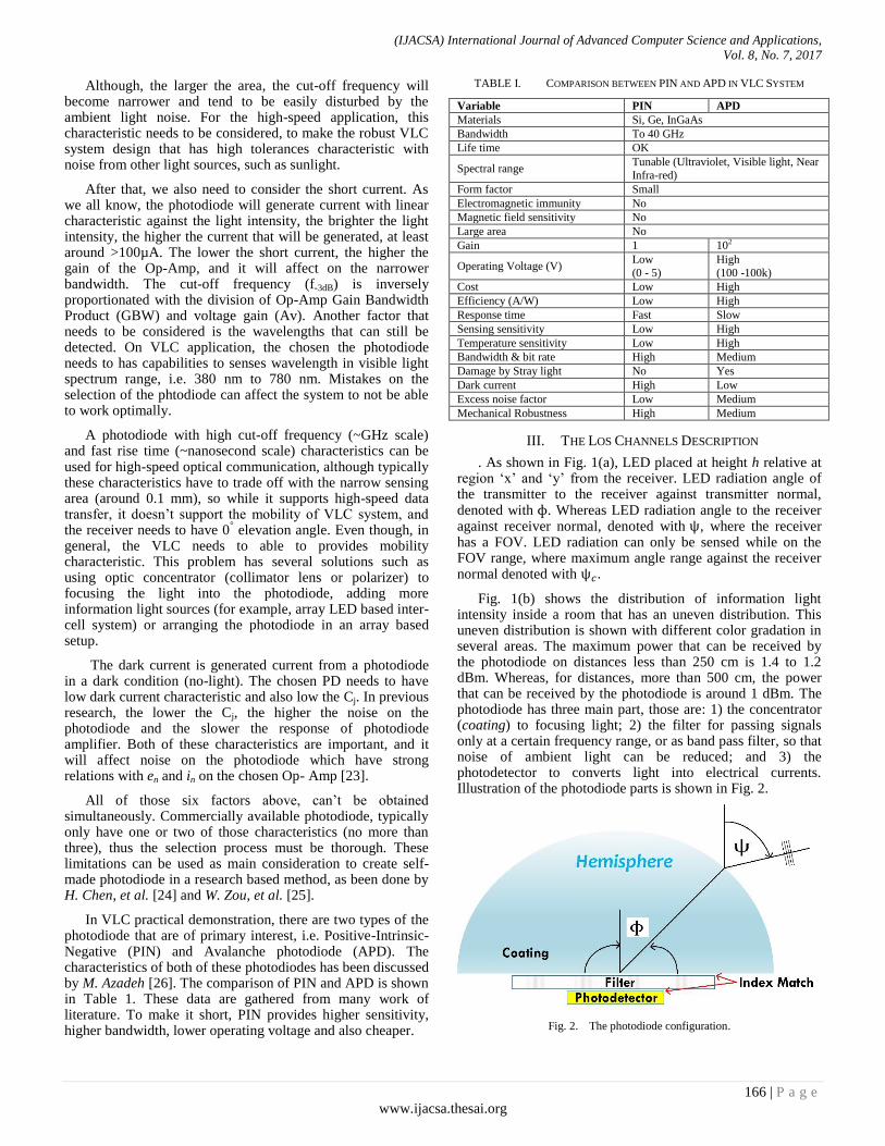
Fig. 1(b) shows the distribution of information light intensity inside a room that has an uneven distribution. This uneven distribution is shown with different color gradation in several areas. The maximum power that can be received by the photodiode on distances less than 250 cm is 1.4 to 1.2 dBm. Whereas, for distances, more than 500 cm, the power that can be received by the photodiode is around 1 dBm. The photodiode has three main part, those are: 1) the concentrator (coating) to focusing light; 2) the filter for passing signals only at a certain frequency range, or as band pass filter, so that noise of ambient light can be reduced; and 3) the photodetector to converts light into electrical currents. Illustration of the photodiode parts is shown in Fig. 2.
Fig. 2. The photodiode configuration.

(IJACSA) International Journal of Advanced Computer Science and Applications,
Vol. 8, No. 7, 2017
167 | P a g e
www.ijacsa.thesai.org
Coating and filter have an effect on the received light on the photodiode, the coating will yield different refractive index of light which propagated from outside of the photodiode, so light propagation direction is changed. This phenomenon will be affecting the FOV of the receiver, as well as an effective region of the receiver ( ) which denoted as
), where n parameter is the refractive index of the concentrator and is the maximum angle of FOV on the photodiode. The filter of photodiode is also affecting receiver effective region, this factor is denoted as .
{
Then it will be shown how coating and filter will affecting . First is by ignoring the filter effect, concentrator effect,
and losses in reflection. The receiver will receive the light radiation at an effective area which can be written mathematically as (2), where Ar is the surface area of the photodiode. Then by adding parameter of coating factor, ) and filter factor . The can be expressed as (3).
{
{
For the relationship between optical power transmitted by LED and received by the LED. In this case, the frequency response of the transmitted and received visible light is flat enough and can be denoted as DC gain ( ). Thus, the relations between optical received power (Pr) in watt and optical transmitted power (Pt) could be expressed as (4).
Where,
Where, is radiant Lambertian, then could be expressed as Eq. 6, is the angle irradiance form of the LED, is the order of the Lambertian emission which defined by LED‟s semi-angle at half power ( , where
(
)
.
The intensity of light received by the photodiode has a dividing factor of the quadratic of the distance ( ) of the intensity transmitted by LED. Whereas, received power is a product of received intensity against the effective area of the receiver. Therefore, optical received power can be expressed as (7).
Where, LOS is also equal to (8).
)
Variable denotes the distance between the LED and the photodiode. By substituting (1), (2) and (5) to the (8), DC channel gain function will be obtained (9). Where is equal to .
{
According to calculation, it can be shown that (4) is a multiplication of (9) with and (1), then from (4), an 3D model can be simulated by MATLAB® using parameters that will be obtained in Section IV. To make the analysis become easier, the unit of watt will be transformed into dBm through (10). Another discussion about LoS channels of VLC can be shown in [27]-[29].
IV. DISCUSSION
A. Experiment Set-up
In this experiment, the photodiode manufactured by OSRAM optoelectronics is used. From its datasheet, it can be obtained information that has been explained in Section III. There are five PIN type of photodiode that is used: BPW21, BPW34B, BPX65, SFH213, SFH221. The detail is shown in Table 2, where there are nine variables, i.e., the features of the photodiode, , , , , , , λ, and . While
parameters for simulation experiment is shown in Table 3, where there are three scenarios of simulation. Variable in this experiment is used as static variable because this variable is an intrinsic variable of the photodiode and can‟t be changed.
Based on the recommendation from [30], for an indoor application (assumed dimension of 3 m x 3 m x 3 m) minimum lumen requirement is around 250 to 500 lm/m
2.
Based on that information, LED that is capable of works in that lumen range and has a maximum power of 5 Watt is chosen. The chosen LED is CREE XLamp® XT-E LE which has maximum ~629 lm and configured in parallel so its maximum power is 50 Watt.
The receiver devices is placed at the distances of 3 meters from the information source, and the LED placed on the coordinat (1.5, 1.5, 3), or exactly at the middle of the room. Because in this experiment is use the LoS channel, the reflectivity of the wall can be ignored. In the datasheet, the gain filter and the concentrator is not specified, so these also ignored. The effect of changing transmitter‟s placement coordinate is not addressed in this paper because in this calculation only use a single LED which has been explored before on [11] and [31]. Since the price of the photodiode was changed in every time, the cost factor is not use in product comparison.
On the scenario A, B, and C, (9) is used to be computed in MATLAB®, however in the datasheet of each photodiode, parameters is not specified, so calculation references will be based on (9) and (10).

(IJACSA) International Journal of Advanced Computer Science and Applications,
Vol. 8, No. 7, 2017
168 | P a g e
www.ijacsa.thesai.org
TABLE II. PHOTODIODE SPECIFICATION
TABLE III. EXPERIMENTAL PARAMETERS
B. Scenario I
In this scenario, transmitter‟s angle is a function of received power. Settings of this scenario are = capability
of the photodiode, where this parameter can be found in Table 2. The channel distance is fixed, i.e. 2 meters, with transmitter power 50 Watt and is changed from minimal
15o and maximum 90
o with range difference of 15
°. The result
of the simulation is shown in Fig. 3.
From that figure, it can be known that the larger , the
smaller received power in the photodiode. This is matched with the characteristic of the LoS channel, where the received power will be larger if the deviation angle of the receiver from the transmitter is closer to 0
°.
BPX65 and SFH213 have similarities in physical area, the same with BPX65 and SFH213. Even though there are differences in FOV, the received power is relatively the same if semi-angle half power is changed. This is because and the refractive index of the lens (n) are not included in the calculation.
Fig. 3. Semi-angle half power of the transmitter vs photodiode‟s received
power.
Variable Notation BPW21 BPW 34B BPX 65 SFH 213 SFH 221
Features - Si PD for the Visible
Spectral Range
Si PD with Enhanced
Blue Sensitivity Si PIN PD Si PIN PD Si Dual PD
Physical area of photo-detector ( ) 7.45 7.45 1 1 1.54
Spectral response range ( ) λ 350 – 820 350 – 1100 350 – 1100 400 – 1100 400 – 1100
Short circuit current at 100 lux ( ) 10 7.4 10 125 24
Terminal Capacitance ( ) 580 72 11 11 25
Half angle (o) 55 60 40 10 55
Gain of optical filter - - - - -
Spectral sensitivity ( ) S 10 75 10 - 24
Total power dissipation ( ) 250 150 250 150 50
Variable Notation Scenario A Scenario B Scenario C
Room dimension x x 3m x 3m x 3m
Transmitter coordinator - Center (1.5, 1.5, 3)
Number of Transmitter - Single LED
Reflectivity of wall γ ignored
PD concentrator refractive index n ignored
Gain of optical filter ignored
Field of view (FOV) semi angle of the receivers Sesuai kemampuan PD
Transmitter‟s semi-angle at half power 15o, 30o, 45o, 60o, 75o, 90o
45o
Distance between LED and PD d 2 m 0.5m, 1 m, 1.5m, 2 m, 2.5m, 3m 2m
Maximum optical power of LED PLED 50 W 5W, 10W, 20W, 30W, 40W, 50W
(IJACSA) International Journal of Advanced Computer Science and Applications,
Vol. 8, No. 7, 2017
169 | P a g e
www.ijacsa.thesai.org
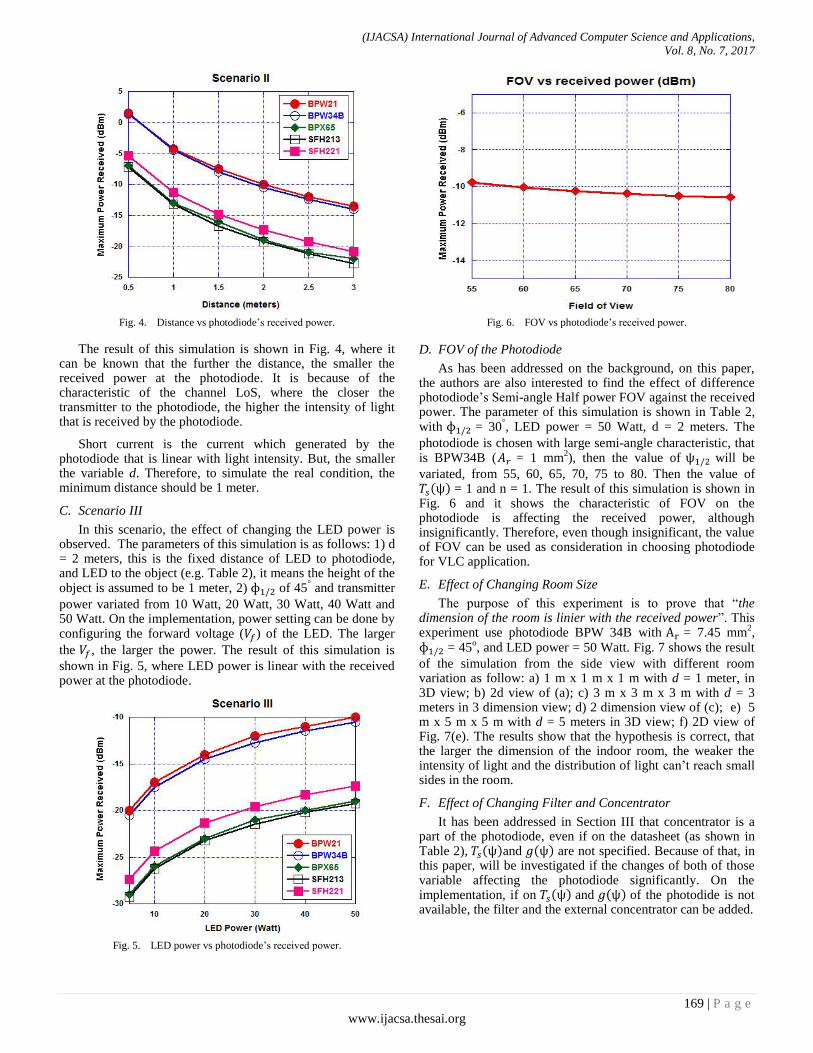
Fig. 4. Distance vs photodiode‟s received power.
The result of this simulation is shown in Fig. 4, where it can be known that the further the distance, the smaller the received power at the photodiode. It is because of the characteristic of the channel LoS, where the closer the transmitter to the photodiode, the higher the intensity of light that is received by the photodiode.
Short current is the current which generated by the photodiode that is linear with light intensity. But, the smaller the variable d. Therefore, to simulate the real condition, the minimum distance should be 1 meter.
C. Scenario III
In this scenario, the effect of changing the LED power is observed. The parameters of this simulation is as follows: 1) d = 2 meters, this is the fixed distance of LED to photodiode, and LED to the object (e.g. Table 2), it means the height of the object is assumed to be 1 meter, 2) of 45
° and transmitter
power variated from 10 Watt, 20 Watt, 30 Watt, 40 Watt and 50 Watt. On the implementation, power setting can be done by configuring the forward voltage ( ) of the LED. The larger
the , the larger the power. The result of this simulation is
shown in Fig. 5, where LED power is linear with the received power at the photodiode.
Fig. 5. LED power vs photodiode‟s received power.
Fig. 6. FOV vs photodiode‟s received power.
D. FOV of the Photodiode
As has been addressed on the background, on this paper, the authors are also interested to find the effect of difference photodiode‟s Semi-angle Half power FOV against the received power. The parameter of this simulation is shown in Table 2, with = 30
°, LED power = 50 Watt, d = 2 meters. The
photodiode is chosen with large semi-angle characteristic, that is BPW34B ( = 1 mm
2), then the value of will be
variated, from 55, 60, 65, 70, 75 to 80. Then the value of = 1 and n = 1. The result of this simulation is shown in Fig. 6 and it shows the characteristic of FOV on the photodiode is affecting the received power, although insignificantly. Therefore, even though insignificant, the value of FOV can be used as consideration in choosing photodiode for VLC application.
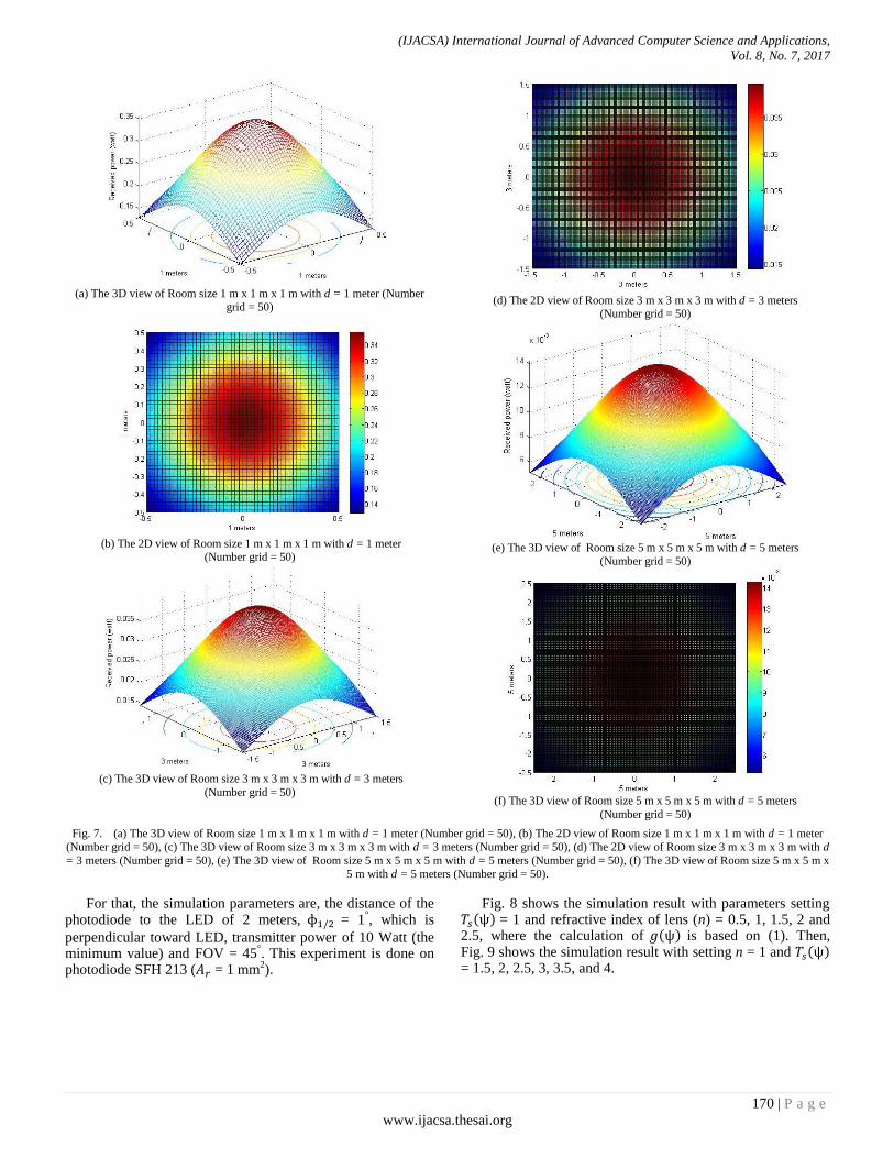
E. Effect of Changing Room Size
The purpose of this experiment is to prove that “the dimension of the room is linier with the received power”. This experiment use photodiode BPW 34B with = 7.45 mm
2,
= 45o, and LED power = 50 Watt. Fig. 7 shows the result
of the simulation from the side view with different room variation as follow: a) 1 m x 1 m x 1 m with d = 1 meter, in 3D view; b) 2d view of (a); c) 3 m x 3 m x 3 m with d = 3 meters in 3 dimension view; d) 2 dimension view of (c); e) 5 m x 5 m x 5 m with d = 5 meters in 3D view; f) 2D view of Fig. 7(e). The results show that the hypothesis is correct, that the larger the dimension of the indoor room, the weaker the intensity of light and the distribution of light can‟t reach small sides in the room.
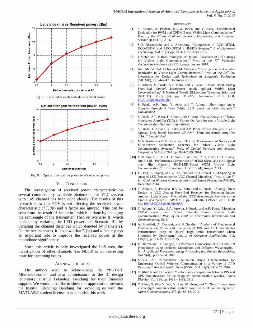
F. Effect of Changing Filter and Concentrator
It has been addressed in Section III that concentrator is a part of the photodiode, even if on the datasheet (as shown in Table 2), and are not specified. Because of that, in this paper, will be investigated if the changes of both of those variable affecting the photodiode significantly. On the implementation, if on and of the photodide is not available, the filter and the external concentrator can be added.
(IJACSA) International Journal of Advanced Computer Science and Applications,
Vol. 8, No. 7, 2017
170 | P a g e
www.ijacsa.thesai.org
(a) The 3D view of Room size 1 m x 1 m x 1 m with d = 1 meter (Number
grid = 50)
(b) The 2D view of Room size 1 m x 1 m x 1 m with d = 1 meter
(Number grid = 50)
(c) The 3D view of Room size 3 m x 3 m x 3 m with d = 3 meters
(Number grid = 50)
(d) The 2D view of Room size 3 m x 3 m x 3 m with d = 3 meters
(Number grid = 50)
(e) The 3D view of Room size 5 m x 5 m x 5 m with d = 5 meters
(Number grid = 50)
(f) The 3D view of Room size 5 m x 5 m x 5 m with d = 5 meters
(Number grid = 50)
Fig. 7. (a) The 3D view of Room size 1 m x 1 m x 1 m with d = 1 meter (Number grid = 50), (b) The 2D view of Room size 1 m x 1 m x 1 m with d = 1 meter
(Number grid = 50), (c) The 3D view of Room size 3 m x 3 m x 3 m with d = 3 meters (Number grid = 50), (d) The 2D view of Room size 3 m x 3 m x 3 m with d
= 3 meters (Number grid = 50), (e) The 3D view of Room size 5 m x 5 m x 5 m with d = 5 meters (Number grid = 50), (f) The 3D view of Room size 5 m x 5 m x
5 m with d = 5 meters (Number grid = 50).
For that, the simulation parameters are, the distance of the photodiode to the LED of 2 meters, = 1
°, which is
perpendicular toward LED, transmitter power of 10 Watt (the minimum value) and FOV = 45
°. This experiment is done on
photodiode SFH 213 ( = 1 mm2).
Fig. 8 shows the simulation result with parameters setting = 1 and refractive index of lens (n) = 0.5, 1, 1.5, 2 and 2.5, where the calculation of is based on (1). Then, Fig. 9 shows the simulation result with setting n = 1 and = 1.5, 2, 2.5, 3, 3.5, and 4.
(IJACSA) International Journal of Advanced Computer Science and Applications,
Vol. 8, No. 7, 2017
171 | P a g e
www.ijacsa.thesai.org
Fig. 8. Lens index vs photodiode‟s received power.
Fig. 9. Optical filter gain vs photodiode‟s received power.
V. CONCLUSION
The investigation of received power characteristic on several commercially available photodiode for VLC system with LoS channel has been done clearly. The results of this research show that FOV is not affecting the received power characteristic if and n factor are ignored. This can be seen from the result of Scenario I which is done by changing the semi-angle of the transmitter. Then on Scenario II, which is done by variating the LED power and Scenario III, by variating the channel distances which denoted by d (meters). On the next scenario, it is known that and n factor plays an important role to improve the received power at the photodiode significantly.
Since this article is only investigated the LoS area, the investigation of other channels (i.e. NLoS) is an interesting topic for upcoming issues.
ACKNOWLEDGEMENT
The authors wish to acknowledge the “PUT-PT Mikroelektronik” and also administrator at the IC design laboratory, Institut Teknologi Bandung for their financial support. We would also like to show our appreciation towards the Institut Teknologi Bandung for providing us with the MATLAB® student license to accomplish this work.
REFERENCES
[1] T. Adiono, A. Pradana, R.V.W. Putra, and Y. Aska, “Experimental Evaluation for PWM and OFDM Based Visible Light Communication,” Proc. of the 2nd Int. Conf. on Electrical Engineering and Computer Science (ICEECS), 2016.
[2] S.D. Dissanayake and J. Armstrong, “Comparison of ACO-OFDM, DCO-OFDM and ADO-OFDM in IM/DD Systems,” J. of Lightwave Technology, Vol. 31(7), pp. 1063- 1072, April 2013.
[3] I. Stefan and H. Haas, “Analysis of Optimal Placement of LED Arrays for Visible Light Communication,” Proc. of the 77th Vehicular Technology Conference (VTC Spring), January 2014.
[4] A-E. Marcu, R-A. Dobre, and M. Vlădescu, “Investigation on Available Bandwidth in Visible-Light Communications,” Proc. of the 22nd Int. Symposium for Design and Technology in Electronic Packaging (SIITME), pp. 244-247, December 2016.
[5] T. Adiono, S. Fuada, A.P. Putra, and Y. Aska, “Desain Awal Analog Front-End Optical Transceiver untuk aplikasi Visible Light Communication,” J. Nasional Teknik Elektro dan Teknologi Informasi (JNTETI), Vol.5 (4), pp. 319-327, November 2016. DOI: 10.22146/jnteti.v5i4.280.
[6] S. Fuada, A.P. Putra, Y. Aska, and T. Adiono, “Short-range Audio Transfer through 3 Watt White LED based on LOS channels,” Unpublished.
[7] S. Fuada, A.P. Putra, T. Adiono, and Y. Aska, “Noise Analysis of Trans-impedance Amplifier (TIA) in Variety Op Amp for use in Visible Light Communication System,” unpublished.
[8] S. Fuada, T. Adiono, Y. Aska, and A.P. Putra, “Noise Analysis in VLC Optical Link based Discrette OP-AMP Trans-Impedance Amplifier (TIA),” Unpublished.
[9] M.A. Kashani and M. Kavehrad, “On the Performance of Single- and Multi-carrier Modulation Schemes for Indoor Visible Light Communication Systems,” Proc. of Optical Networks and Systems Symposium GLOBECOM, pp. 2084-2089, 2014.
[10] F. M. Wu, C. T. Lin, C. C. Wei, C. W. Chen, Z. Y. Chen, H. T. Huang, and S. Chi, “Performance Comparison of OFDM Signal and CAP Signal over High Capacity RGB-LED-Based WDM Visible Light Communication,” IEEE Photonics J., Vol. 5, (4), August 2013.
[11] J. Ding, K. Wang, and Z. Xu, “Impact of Different LED-Spacing in Arrayed LED Transmitter on VLC Channel Modeling,” Proc. of the 6th Int. Conf. on Wireless Communications and Signal Processing (WCSP), December 2014.
[12] T. Adiono, A. Pradana, R.V.W. Putra, and S. Fuada, “Analog Filters Design in VLC Analog Front-End Receiver for Reducing Indoor Ambient Light Noise,” Proc. of the IEEE Asia Pacific Conference on Circuit and Systems (APCCAS), pp. 581-584, October 2016. DOI: 10.1109/APCCAS.2016.7804058.
[13] T. Adiono, Y. Aska, A.A. Purwita, S. Fuada, and A.P. Putra, “Modeling OFDM system with Viterbi Decoder Based Visible Light Communication,” Proc. of Int. Conf. on Electronics, Information, and Communication, 2017.
[14] A. Boudkhil, A. Ouzzani, and B. Soudini, “Analysis of Fundamental Photodetection Noises and Evaluation of PIN and APD Photodiodes Performances using an Optical High Debit Transmission Chain Simulated by Optisystem,” Int. J. of Computer Applications, Vol. 115(18), pp. 21-29, April 2015.
[15] P. Sharma and H. Sarangal, “Performance Comparison of APD and PIN Photodiodes using Different Modulation and Different Wavelengths,” Int. J. of Signal Processing, Image Processing and Pattern Recognition. Vol. 9(4), pp.257-264, 2016.
[16] M.A.A. Ali, “Transmitter Inclination Angle Characteristics for Underwater Optical Wireless Communication in a Variety of APD Detectors,” World Scientific News (WSN), Vol. 45(2), 355-372, 2016.
[17] O. Kharraz and D. Forsyth, “Performance comparisons between PIN and APD photodetectors for use in optical communication systems,” Optik Elsevier, Vol. 124, pp. 1493 – 1498, 2013.
[18] Y. Chen, S. Wen Y. Wu, Y. Ren, W. Guan, and Y. Zhou, “Long-range visible light communication system based on LED collimating lens,” Optics Communications, 377, pp. 83–88, 2016.

(IJACSA) International Journal of Advanced Computer Science and Applications,
Vol. 8, No. 7, 2017
172 | P a g e
www.ijacsa.thesai.org
[19] S. Fuada and T. Adiono, “Pengaruh Junction Capacitor (Cj) Photodiode terhadap Noise pada TIA untuk Aplikasi Visible Light Communications (VLC),” unpublished.
[20] S. Fuada, A.P. Putra, Y. Aska and T. Adiono, “A First Approach to Design Mobility Function and Noise Filter in VLC System Utilizing Low-cost Analog Circuits ,” Int. J. of Recent Contributions from Engineering, Science, and IT (iJES), Vol.5(2), pp. 14-30, 2017.
[21] K. Lee, H. Park, and J. R. Barry, “Indoor Channel Characteristics for Visible Light Communications,” IEEE Communications Letters, pp. 1-3, 2015.
[22] J-H Li, et al., “An integrated PIN-array receiver for visible light communication,” J. Opt. 17,105805, pp. 1-5, 2015.
[23] T. Adiono, R.V.W. Putra, and S. Fuada, “Noise and Bandwidth Considerations in Designing Op-Amp Based Transimpedance Amplifier for VLC,” unpublished.
[24] H. Chen, P. Verheyen, P. De Heyn, G. Lepage, J. De Coster, S. Balakrishnan, P. Absil, W. Yao, L. Shen, G. Roelkens, and J. Van Campenhout, “1 V bias 67 GHz bandwidth Si-contacted germanium waveguide P-I-N photodetector for optical links at 56 Gbps and beyond,” Optics Express, Vol. 24(5), pp. 4622-463, 2016.
[25] W. Zou, Y. Xia, D. Chen, and Y. Zeng, “A High-Speed Lateral PIN Polysilicon Photodiode on Standard Bulk CMOS Process,” Elsevier: Solid-State Electronics, December 2016. DOI: http://dx.doi.org/10.1016/j.sse.2016.12.005.
[26] M. Azadeh, PIN and APD detectors. Fiber Optics Engineering-Optical Networks, Springer Science+Business Media, 2009.
[27] T. Komine, S. Haruyama and M. Nakagawa, “A Study of Shadowing on Indoor Visible-Light Wireless Communication Utilizing Plural White LED Lightings,” Wireless Personal Communications 34, pp. 211–225, 2005.
[28] M.V. Bhalerao, M. Sumathi, and S.S. Sonavane, “Line of sight model for visible light communication using Lambertian radiation pattern of LED,” Int. J. Commun Syst, pp. 1-7, 2016.
[29] Y. Qiu, H-H. Chen, and W-Xi. Meng, “Channel modeling for visible light communications - a survey,” Wirel. Commun. Mob. Comput., pp. 1-19, 2016.
[30] T.Adiono and S. Fuada, “Desain dan Implementasi LED Driver Linier untuk Aplikasi Visible Light Communication,” Unpublished.
[31] C-W. Chow, Y. Liu, C-H. Yeh, C-Y Chen, C-N. Lin, and D-Z. Hsu, “Secure communication zone for white-light LED visible light communication,” Optics Communications, Vol. 344, pp. 81–85, 2015.
[32] Z. Ghassemlooy, W. Popoola, and S. Rajbhandari, “Optical Wireless Communications System and Channle Modelling with MATLAB®,” Boca Raton: CRC Press Taylor and Francis Group, 2013.
APPENDIX
In this work, the MATLAB® computations are adopted from [32]. In
order to obtain specific point, the authors modify from 3D model to 2D model
and then analyze by viewing maximum point of curve characteristic (shown in Fig. 10). A sample of the MATLAB® codes to calculate the LoS channel gain
of variety commercial photodiode based 2D view is shown in the program
below: theta=45; %semi-angle at half power
m=-log10(2)/log10(cosd(theta)); %lambertian order of emission
P_total=50;%transmitted optical power by individual LED
Adet=1.54e-3; %detector physical area of a photodiode in cm
FOV=55*pi/180;%FOV at receiver
lx=3; ly=3; lz=3; %room dimension in meter
h=2; %the distance between source and receiver plane
XT=0; YT=0; %position of LED Nx=lx*25; Ny=ly*25;%number of grid receiver plane
x=-lx/2:lx/Nx:lx/2;y=-ly/2:ly/Ny:ly/2;[XR,YR]=meshgrid(x,y);
%receiver plane grid
D1=sqrt((XR-XT(1,1)).^2+(YR-YT(1,1)).^2+h^2); %distance vector from source 1
cosphi_A1=h./D1; %angle vector
H_A1=(m+1)*Adet.*cosphi_A1.^(m+1)./((pi)*D1.^2); %channel DC gain for source 1
P_rec=P_total.*H_A1;
%received power from source 1
P_rec_dBm=10*log10(P_rec);
plot(max(P_rec_dBm));
Fig. 10. The 2D view of maximum point of the photodiode‟s received power
at -17.36 dBm.
AUTHORS PROFILES
Syifaul Fuada received B. Ed degree on Electrical Engineering Education major from State University of Malang (UM), Indonesia in 2014/2015 and M. Sc degree on Microelectronics engineering major, School of Electrical Engineering and Informatics Institut Teknologi Bandung, Indonesia in 2016/2017. Currently he is working in University
Center of Excellence on Microelectronics Institut Teknologi Bandung. His research interests include Analog circuits design, instrumentation system, circuit simulation, engineering education, multimedia learning, game
conceptor, and Visible Light Communication.
Angga Pratama Putra received his B. Sc. and M.Cs degree in Electrical Engineering from Institut Teknologi Bandung (ITB), Indonesia. His research interests include Embedded System, Software Engineering, VLSI, System-on-Chip, Internet of Things, Digital Signal Processing (DSP) and Visible Light
Communication (VLC).
Trio Adiono obtained his Ph. D. degree in VLSI Design from Tokyo Institute of Technology, Japan, in 2002. Currently, he is a lecturer at the School of Electrical Engineering and Informatics, a Head of the Microelectronics Center and IC Design Laboratory, ITB. He currently serves as a chair of the IEEE SSCS Indonesia Chapter. His research
interests include VLSI, Signal and Image Processing, Visible Light Communication, Smart Card, Electronics Solution Design and Integration.