Embed Size (px)
Citation preview
Degree project inCommunication Systems
Second level, 30.0 HECStockholm, Sweden
V E N K A T E S H C H E N G E G O W D A
Two Party Video Calls
Analysis of Queues for Interactive Voiceand Video Response Systems
K T H I n f o r m a t i o n a n d
C o m m u n i c a t i o n T e c h n o l o g y
Analysis of Queues for Interactive Voice and Video Response Systems
Two Party Video Calls
Venkatesh Chengegowda [email protected]
Master thesis
16 September 2012
Examiner & Academic Supervisor: Gerald Q. Maguire Jr. Industry Advisor: Hans-Christer Bergschöld, WX3 Telecom AB ([email protected])
KTH Royal Institute of Technology School of Information and Communication Technology
Stockholm, Sweden

i
Abstract Video conversation on mobile devices is popularizing with the advent of 3G. The enhanced
network capacity thus available enables transmission of video data over the internet. It has been
forecasted by several VOIP service organizations that the present IVR systems will evolve into Voice
and Video Response (IVVR) Systems. However, this evolution has many technical challenges on the
way. Architectures to implement queuing systems for video data and standards for inter conversion of
video data between the formats supported by calling parties are two of these challenges. This thesis is
an analysis of queues and media transcoding for IVVRs.
A major effort in this work involves constructing a prototype IVVR queuing system. The system
is constructed by using an open source server named Asterisk and MySql database. Asterisk is a SIP
based Public Exchange Server (PBX) and also a development environment for VOIP based IVRs.
Functional scenarios for SIP session establishment and the corresponding session setup times for this
queueing model are measured. The results indicate that the prototype serves as a sufficient model for a
queue, although a significant delay is introduced for session establishment. The work also includes
analysis of integrating DiaStar™, is a SIP based media transcoding engine to this queue. However, this
system is not complete to function with DiaStar for media translation. The study concludes with a
mention of the areas for future work on this particular system and the general state of IVVR queuing
systems in the industry.
Keywords: IVVR, Queue, media transcoding, SIP, Asterisk, DiaStar™

iii
Sammanfattning Videosamtal på mobila enheter är popularisera med tillkomsten av 3G. Den förbättrade
nätkapacitet så tillgänglig möjliggör överföring av videodata över Internet. Det har prognos av flera
VOIP serviceorganisationer att de nuvarande IVR-system kommer att utvecklas till röst och video
Response (IVVR) System. Dock har denna utveckling många tekniska utmaningar på vägen.
Arkitekturer för att genomföra kösystem för videodata och standarder för bland konvertering av
videodata mellan format som stöds för uppringande är två av dessa utmaningar. Denna avhandling är
en analys av köer och media kodkonvertering för IVVRs.
En stor insats i detta arbete innebär att bygga en prototyp IVVR kösystem. Systemet är
konstruerat med hjälp av en öppen källkod-server som heter Asterisk och MySQL-databas. Asterisk är
en SIP-baserad Public Exchange Server (PBX) och även en utvecklingsmiljö för VOIP-baserade IVRs.
Funktionella scenarier för SIP session etablering och motsvarande sessionen inställningar för den
föreslagna kö modell mäts. Resultaten indikerar att prototypen tjänar som en tillräcklig modell för en
kö, även om en betydande fördröjning införs för sessionsupprättandebegäran. Arbetet omfattar även
analys av integrering DiaStar™ är en SIP-baserad media kodkonvertering motor till denna kö.
Emellertid är detta system inte helt att fungera med DiaStar för media translation. The studie avslutas
med ett omnämnande av de områden för framtida arbete med detta system och det allmänna tillståndet
i IVVR kö-system i branschen.
Nyckelord: IVVR , kö , media omkodning , SIP, Asterisk , DiaStar™

v
Acknowledgements First and foremost, I extend my deep gratitude to Professor Gerald Q. Maguire Jr for mentoring
me throughout my thesis period. His immense knowledge and support provided me the necessary technical insight and also motivation to carry out this work.
I also thank Hans Christer Berg Schöld, Torbjörn Abrahamsson and Per Åke of WX3 Telecom AB for providing me an opportunity for working on this project and for the valuable technical inputs during the execution.
I like to extend my special thanks to my fiancé Anitha Narasimhan for having the patience to often listen all the technical details I described while I was implementing the prototype and motivating me throughout.
I want to express my infinite gratitude to my family for providing me moral support.
Stockholm,
Venkatesh Changegowda

vii
Table of Contents
Abstract ......................................................................................................................................... i
Sammanfattning ......................................................................................................................... iii
Acknowledgements ..................................................................................................................... v
List of Figures ............................................................................................................................. ix
List of Tables ............................................................................................................................... xi
List of Abbreviations and Acronyms ...................................................................................... xiii
1 Introduction ......................................................................................................................... 1
1.1 Goals ............................................................................................................................... 1 1.2 Structure of this thesis ..................................................................................................... 1
2 Background ......................................................................................................................... 3
2.1 Queuing Theory ............................................................................................................... 3 2.1.1 Terminology ............................................................................................................. 3 2.1.2 Little's Law ............................................................................................................... 4
2.2 IVVR Systems .................................................................................................................. 4 2.2.1 Introduction .............................................................................................................. 5 2.2.2 Technical Challenges ............................................................................................... 6
3 Signalling Protocols ............................................................................................................ 9
3.1 H.323 ............................................................................................................................... 9 3.2 Session Initiation Protocol (SIP) ...................................................................................... 9
3.2.1 SIP Components ...................................................................................................... 9 3.2.2 SIP Methods .......................................................................................................... 10 3.2.3 SIP Status Codes .................................................................................................... 11 3.2.4 SIP Scenarios ......................................................................................................... 11
3.3 SDP ............................................................................................................................... 13 3.4 RTP/RTCP ..................................................................................................................... 13
3.4.1 RTP ........................................................................................................................ 14 3.4.2 RTCP ..................................................................................................................... 15
3.5 DTMF ............................................................................................................................. 15 3.6 NAT Traversal ................................................................................................................ 15
3.6.1 Types of NAT ......................................................................................................... 16 3.6.2 SIP-NAT Issues...................................................................................................... 16
viii
4 Component Systems ......................................................................................................... 19
4.1 Asterisk .......................................................................................................................... 19 4.1.1 Dialplan .................................................................................................................. 19 4.1.2 SIP Configuration ................................................................................................... 20
4.2 DiaStar ........................................................................................................................... 20 4.3 SIP Clients ..................................................................................................................... 22
4.3.1 What are SIP phones? ........................................................................................... 22 4.3.2 Linphone ................................................................................................................ 23
5 Methods .............................................................................................................................. 25
5.1 Queue Architecture ........................................................................................................ 25 5.1.1 Development Environment .................................................................................... 25 5.1.2 Component Diagram.............................................................................................. 25 5.1.3 Scenario 1: DiaStar facing the callers.................................................................... 29 5.1.4 Scenario 2: Asterisk facing callers ......................................................................... 29 5.1.5 Queue Flow Chart .................................................................................................. 30
5.2 DiaStar Integration ......................................................................................................... 34 5.2.1 Calls Terminating on DiaStar ................................................................................. 34 5.2.2 Conferencing with DiaStar ..................................................................................... 34
6 Measurements ................................................................................................................... 37
6.1 Basic test cases ............................................................................................................. 37 6.1.1 One Agent-One Caller ........................................................................................... 37 6.1.2 One Agent-Many Callers ....................................................................................... 38 6.1.3 Agent Logs in While Callers are in Queue ............................................................ 39 6.1.4 Many Agents-One Caller ....................................................................................... 40
6.2 Queue Performance Statistics ....................................................................................... 41 6.2.1 Regular SIP Call Setup .......................................................................................... 41 6.2.2 Queue Call Setup .................................................................................................. 41 6.2.3 Inferences .............................................................................................................. 42
7 Conclusion ......................................................................................................................... 43
7.1 Future work .................................................................................................................... 43 7.1.1 NAT Traversal ........................................................................................................ 43 7.1.2 Transcoding ........................................................................................................... 43 7.1.3 Call back queue ..................................................................................................... 43
7.2 Required reflections ....................................................................................................... 43 Bibliography............................................................................................................................... 45
ix
List of Figures Figure 2-1: An M/M/n queuing model ...................................................................................................... 4 Figure 3-1: SIP Methods at the calling UA ............................................................................................. 11 Figure 3-2: SIP Register Scenario ......................................................................................................... 12 Figure 3-3: Two Party Call Scenario ...................................................................................................... 12 Figure 3-4: RTP Header ........................................................................................................................ 14 Figure 4-1: DiaStar Asterisk Integration ................................................................................................. 21 Figure 4-2: Ideal Queue Scenario with Transcoding ............................................................................. 22 Figure 5-1: Component Diagram ........................................................................................................... 26 Figure 5-2: DiaStar facing Callers ......................................................................................................... 29 Figure 5-3: Asterisk facing Callers ......................................................................................................... 29 Figure 5-4: Agent Register Flow ............................................................................................................ 31 Figure 5-5: Queue Caller Flow .............................................................................................................. 32 Figure 5-6: Basic DiaStar-Asterisk Topology ......................................................................................... 34 Figure 5-7: Conferencing with DiaStar .................................................................................................. 35 Figure 6-1: One Agent One Caller Test ................................................................................................. 38 Figure 6-2: One Agent Many Callers Test-1 .......................................................................................... 38 Figure 6-3: One Agent Many Callers Test-2 .......................................................................................... 39 Figure 6-4: Agent Logs in while Callers are in Queue ........................................................................... 39 Figure 6-5: Many Agents One Caller-1 .................................................................................................. 40 Figure 6-6: Many Agents One Caller-2 .................................................................................................. 40

xi
List of Tables Table 2-1: Parameters that describe a queue ......................................................................................... 3 Table 2-2: Bandwidth available in some different types of networks ....................................................... 7 Table 2-3: Approximate Data Rates for Video Formats ........................................................................... 8 Table 3-1: SIP's logical components ........................................................................................................ 9 Table 3-2: SIP Methods ......................................................................................................................... 10 Table 3-3: SIP Status Codes ................................................................................................................... 11 Table 3-4: Fields of the SDP protocol .................................................................................................... 13 Table 3-5: Fields of the RTP header ...................................................................................................... 14 Table 3-6: RTCP Message Types .......................................................................................................... 15 Table 3-7: Types of NATs ....................................................................................................................... 16 Table 5-1: Test environment .................................................................................................................. 25 Table 6-1: Regular SIP Call Setup Time (all times in seconds) ............................................................. 41 Table 6-2: SIP Call Setup Time with Queue (all times in seconds) ....................................................... 41

xiii
List of Abbreviations and Acronyms
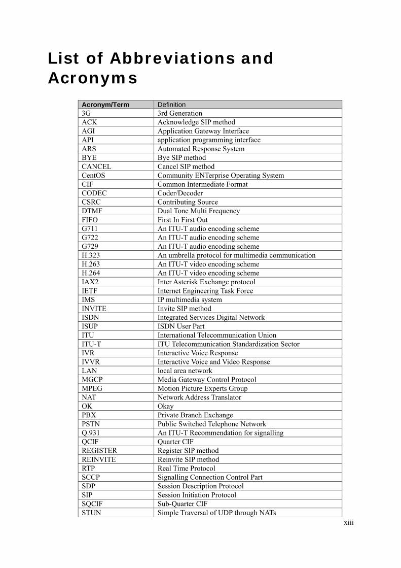
Acronym/Term Definition 3G 3rd Generation ACK Acknowledge SIP method AGI Application Gateway Interface API application programming interface ARS Automated Response System BYE Bye SIP method CANCEL Cancel SIP method CentOS Community ENTerprise Operating System CIF Common Intermediate Format CODEC Coder/Decoder CSRC Contributing Source DTMF Dual Tone Multi Frequency FIFO First In First Out G711 An ITU-T audio encoding scheme G722 An ITU-T audio encoding scheme G729 An ITU-T audio encoding scheme H.323 An umbrella protocol for multimedia communication H.263 An ITU-T video encoding scheme H.264 An ITU-T video encoding scheme IAX2 Inter Asterisk Exchange protocol IETF Internet Engineering Task Force IMS IP multimedia system INVITE Invite SIP method ISDN Integrated Services Digital Network ISUP ISDN User Part ITU International Telecommunication Union ITU-T ITU Telecommunication Standardization Sector IVR Interactive Voice Response IVVR Interactive Voice and Video Response LAN local area network MGCP Media Gateway Control Protocol MPEG Motion Picture Experts Group NAT Network Address Translator OK Okay PBX Private Branch Exchange PSTN Public Switched Telephone Network Q.931 An ITU-T Recommendation for signalling QCIF Quarter CIF REGISTER Register SIP method REINVITE Reinvite SIP method RTP Real Time Protocol SCCP Signalling Connection Control Part SDP Session Description Protocol SIP Session Initiation Protocol SQCIF Sub-Quarter CIF STUN Simple Traversal of UDP through NATs

xiv
Acronym/Term Definition UA User Agent UAC User Agent Client UAS User Agent Server VoIP Voice over Internet Protocol YCrBr Luminance, red chrominance, and blue chrominance color
scheme

1
1 Introduction A high quality real-time video communication experience over the internet demands high data
transmission rates. Until recently, it was a privilege available only to selected consumers who could afford the high costs involved in high speed network connections. However, with the increasing deployment of 3G networks, several commercial operators are providing the infrastructure for high bandwidth network connections for mobile users at affordable prices. There is already wide deployment of broadband fixed networks in Sweden and many other countries. The availability of broadband connectivity is triggering significant changes in the prevailing communication applications. For example, Voice over Internet Protocol (VoIP) is replacing Public Switched Telephone Network (PSTN) for calls, and video calls are growing increasingly popular. As a result, Interactive Voice Response (IVR) systems are expected to be replaced by Interactive Voice and Video Response (IVVR) response systems in certain business areas. Healthcare systems, where patients contact medical personnel are a prominent business area demanding IVVR systems. [1]
Along with the demand for enhanced network capacity, widespread usage of IVVR systems introduces several other technical challenges. Some of these challenges [2]:
• Queuing architectures for IVVR systems are still in an early stage of development. • If the clients of the calling parties use different video CODECs, there are no standard
protocols to transcode the media. • A large number of end devices are using private IP addresses that are valid only within a local
area network (LAN). Unfortunately this causes problems for the Session Initiation Protocol (SIP); a prominent signalling protocol used for IP based media communication.
• Synchronization of voice and video streams and utilization of the available bandwidth are not optimal.
1.1 Goals This thesis addresses the need for queuing architectures and mechanisms to handle transcoding
of media between various encoding schemes. Accordingly, this thesis project has explored a number of related architectural concepts. A simple architecture to implement a queue is proposed and a prototype IVVR system was implemented using two open source applications (specifically, Asterisk and DiaStar). Asterisk is a media signalling and call routing application. DiaStar is a media transcoding engine that has been used to generate, stream and convert video data. Asterisk and DiaStar use the Woomera protocol to communicate with each other.
1.2 Structure of this thesis This first chapter defines the context and scope of this thesis. It briefly explains what the
acronym IVVR means and describes what has been implemented and evaluated as a part of this thesis project.
The second chapter provides the background information necessary to understand the subsequent chapters of the thesis. It covers the basic concepts of queuing theory, signalling and media transfer protocols, and gives some practical information about Asterisk and DiaStar . The first section of this chapter describes the standard metrics used to measure the performance of a queuing system.
The third chapter describes the various protocols that will be utilized throughout the thesis project. This chapter also presented a means of dealing with the problem of private addresses in the LAN and how to overcome the problems introduced by network address translators (NATs).
The fourth chapter describes the subsystems that have been combined to implement and test the prototype system. While the fifth chapter gives a high level architecture of the prototype queue with emphasis on design decisions and technical hurdles encountered during this thesis project. The sixth chapter describes the successful deployment of the prototype application using snapshots of the various subsystems. It also evaluates the performance of the system in terms of the standard queuing metrics.

2
The final chapter outlines the features and drawbacks of the prototype system. It also describes what has been learned during the course of this thesis project and suggests additional work that may be necessary for future IVVR queue applications. This chapter ends with some reflection on the social, economic, and other issues raised by this thesis project.
3
2 Background This chapter introduces the reader to all the technical concepts and software applications used in
this thesis. In depth details of certain aspects have been given when this information is directly used in subsequent sections. It also provides a reader a background in communication networks and TCP/IP protocols with the additional information that they need to understand the rest of this thesis.
2.1 Queuing Theory In order to understand a queuing system we use some formal terminology to describes such
systems (see section 2.1.1). Additionally, to understand the replationship between the time that items spend waiting in a queue and the rate at which requests are services we will utilize Little’s Law (see section 2.1.2).
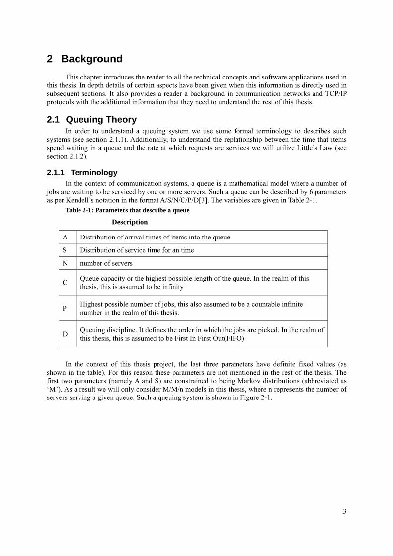
2.1.1 Terminology In the context of communication systems, a queue is a mathematical model where a number of
jobs are waiting to be serviced by one or more servers. Such a queue can be described by 6 parameters as per Kendell’s notation in the format A/S/N/C/P/D[3]. The variables are given in Table 2-1.
Table 2-1: Parameters that describe a queue
Description
A Distribution of arrival times of items into the queue
S Distribution of service time for an time
N number of servers
C Queue capacity or the highest possible length of the queue. In the realm of this thesis, this is assumed to be infinity
P Highest possible number of jobs, this also assumed to be a countable infinite number in the realm of this thesis.
D Queuing discipline. It defines the order in which the jobs are picked. In the realm of this thesis, this is assumed to be First In First Out(FIFO)
In the context of this thesis project, the last three parameters have definite fixed values (as
shown in the table). For this reason these parameters are not mentioned in the rest of the thesis. The first two parameters (namely A and S) are constrained to being Markov distributions (abbreviated as ‘M’). As a result we will only consider M/M/n models in this thesis, where n represents the number of servers serving a given queue. Such a queuing system is shown in Figure 2-1.
4
N
C = Infinity
=Infinity
A=M
S=M
D=FIFO
Figure 2-1: An M/M/n queuing model
2.1.2 Little's Law Little's Law says that the average number of items in a queuing system equals the average rate at
which items arrive multiplied by the average time that an item spends in the system. The derivation and formal proof are given in [4] and [3].
L=AW
Where: L = average number of items in the queuing system
W = average waiting time in the system for an item
A = average number of items arriving per unit time
2.2 IVVR Systems An Automated Response System (ARS) offers many advantages to small and large
organizations by providing recorded answers to frequently asked questions. An ARS can provide answers to callers 24 hours a day, 365 days per year, thus providing high availability while saving the business both time and money. An Interactive Voice Response (IVR) ARS provides voice only communication. The concept of an Interactive Voice and Video Response (IVVR) is an evolution of Interactive Voice Response (IVR) which enables both voice and video communication.
An IVVR ARS enables users to interact with each other (and with services) via a real-time (audio and) video stream. This is commonly known as a video call. Current 3G mobile devices are frequently equipped with cameras and color screens, thus enabling use of IVVRs even from mobile clients. Fixed devices with display screens and SIP soft phones can also be IVVR clients.
5
2.2.1 Introduction An IVVR generally has these properties:
• A display screen that displays a number of options, so that the user can quickly select their desired option rather than having to listen to a spoken list of options (as would be the case in an IVR);
• Alternatively a picture may be displayed that conveys information faster than an audio description. For instance, an online shopping system might displays the available items and the number of these items that are in stock;
• A means to send a recorded video stream; • A means to establish a live audio & video session between two users; • A means to establish a live session involving multiple users; and • A means to record and store (audio and) video [5]
2.2.1.1 Business Value There are three business advantages which drive VoIP and IVR providers to invest in studying
and constructing IVVR systems. These advantages are: Ease of use IVVR services can use innovative ways of pictorially
presenting information; hence make the interface language independent, where as an audio-only IVR mandates that the end user must understand the language in which the audio messages were recorded.
No installation is needed IVVR systems can be designed to be accessed using standard SIP clients, thus no separate installation or configuration is normally needed of the client.
Revenue generation model If the service distributed in an IVVR is commercially valuable, the user can be billed based upon their usage (for example, based upon the call duration or the amount to data streamed). The service can also be deployed through regular and premium dialing numbers for different kinds of users.
2.2.1.2 Interactivity using DTMF The IVVR should provide a mechanism for the user to interact with the system by selecting
their choice from among the available options. This selection can happen at multiple levels in a sequence. With respect to the current video session, the user should be able to initiate the session, terminate, pause, or move to a specified location in the video (as desired). A convenient means to implement this communication is by utilizing the digits 0-9, *, and #. In an IVR system this is frequently done by using the Dual Tone Multi-Frequency (DTMF)[6] signals generated when the user presses these buttons on their “Touch-Tone” telephone. In the case of an IVVR system this could also be implemented by soft-keys, i.e., defined regions of the screen that invoke different functions, or by specific single or mulitiple finger gestures.
6
2.2.1.3 Sources of Video An IVVR can obtain its video (and audio) stream from a variety of sources. The following are
some of the common media sources[7]: Local Video IVVR systems can play audio and video from locally stored video
files. These files can be in standardized formats such as 3GP/MPEG or can be raw H.261/H.263/H.264 streams.
Video servers External servers can store the audio and video files. In such cases, RTSP can be used to control video streaming. RTSP [8] is an application level protocol for controlling the delivery of data with real-time properties. This protocol allows the user to pause and navigate to a desired point in the video.
Static image files Static information in the form of images. It is useful to have the ability to “play” a static file, generating a video stream to the handset. An example usage scenario can be to show the seating arrangement in a hall.
Hairpinning If there are two devices participating in a video communication session and each of them is also a source of video data, the configuration is commonly known as hairpinning. In simple terms, any two party calls occurring within the realm of an IVVR can also be a source of video data.
2.2.2 Technical Challenges Implementation of an IVVR faces several challenges related to transmission of video data. In
addition to all of these challenges, a queue is also necessary. Before we go further it is necessary to introduce the standards and principles of video encoding. H.261, defined by the International Telecommunication Union - Telecommunication Standardization Sector (ITU-T)[9], was the first practical standard used to describe the format of video data to be encoded as a real time protocol (RTP) payload (for details of RTP see section 3.4). H.261 encodes a series of pictures that utilize the YCrBr coloring scheme. The encoded video signal is compressed using a Huffman encoding scheme. H.261 supports frames with two different resolutions, namely Common Intermediate Format (CIF) and Quarter Common Intermediate Format (QCIF). These resolutions are:
CIF encodes frames at a resolution of 352 x 288 pixels.
QCIF encodes frames at a resolution of 176 x 144.
H.262, H.263, and H.264 are improved versions of H.261. The prototype application constructed as a part of this thesis has been tested with H.263. Many popular commercial video encoding formats such as MPEG and MPEG-4 internally use H.263 [2].
G.711, G.723, G.729, G.726, AMR-NB, AMR-WB, and G.722 are the popular audio encoding formats. In this thesis project we have primarily used G.711 (pcma) as the audio encoding formats.
2.2.2.1 Queuing An IVVR Queue is a system wherein a certain number of human operators (known as agents)
accept and establish video calls from a large number of callers in a first in first out (FIFO) order. In order to provide this ordered delivery of video calls to the operators the queuing system should implement the following functions:
• An algorithm to service the users in a FIFO fashion; • A means to identify the state of the agents, i.e., whether they are currently engaged in a session
or are available; • A means to detect the state change of an agent as they transitioning out of a session; and • Upon identifying a free agent, a means to establish a video connection between this agent and
the first caller in the FIFO.
7
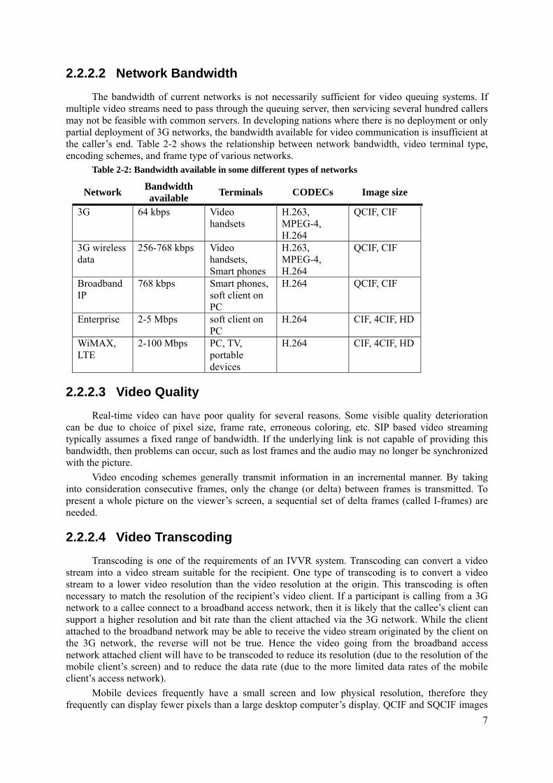
2.2.2.2 Network Bandwidth The bandwidth of current networks is not necessarily sufficient for video queuing systems. If
multiple video streams need to pass through the queuing server, then servicing several hundred callers may not be feasible with common servers. In developing nations where there is no deployment or only partial deployment of 3G networks, the bandwidth available for video communication is insufficient at the caller’s end. Table 2-2 shows the relationship between network bandwidth, video terminal type, encoding schemes, and frame type of various networks.
Table 2-2: Bandwidth available in some different types of networks
Network Bandwidth available Terminals CODECs Image size
3G 64 kbps Video handsets
H.263, MPEG-4, H.264
QCIF, CIF
3G wireless data
256-768 kbps Video handsets, Smart phones
H.263, MPEG-4, H.264
QCIF, CIF
Broadband IP
768 kbps Smart phones, soft client on PC
H.264 QCIF, CIF
Enterprise 2-5 Mbps soft client on PC
H.264 CIF, 4CIF, HD
WiMAX, LTE
2-100 Mbps PC, TV, portable devices
H.264 CIF, 4CIF, HD
2.2.2.3 Video Quality Real-time video can have poor quality for several reasons. Some visible quality deterioration
can be due to choice of pixel size, frame rate, erroneous coloring, etc. SIP based video streaming typically assumes a fixed range of bandwidth. If the underlying link is not capable of providing this bandwidth, then problems can occur, such as lost frames and the audio may no longer be synchronized with the picture.
Video encoding schemes generally transmit information in an incremental manner. By taking into consideration consecutive frames, only the change (or delta) between frames is transmitted. To present a whole picture on the viewer’s screen, a sequential set of delta frames (called I-frames) are needed.
2.2.2.4 Video Transcoding Transcoding is one of the requirements of an IVVR system. Transcoding can convert a video
stream into a video stream suitable for the recipient. One type of transcoding is to convert a video stream to a lower video resolution than the video resolution at the origin. This transcoding is often necessary to match the resolution of the recipient’s video client. If a participant is calling from a 3G network to a callee connect to a broadband access network, then it is likely that the callee’s client can support a higher resolution and bit rate than the client attached via the 3G network. While the client attached to the broadband network may be able to receive the video stream originated by the client on the 3G network, the reverse will not be true. Hence the video going from the broadband access network attached client will have to be transcoded to reduce its resolution (due to the resolution of the mobile client’s screen) and to reduce the data rate (due to the more limited data rates of the mobile client’s access network).
Mobile devices frequently have a small screen and low physical resolution, therefore they frequently can display fewer pixels than a large desktop computer’s display. QCIF and SQCIF images
8
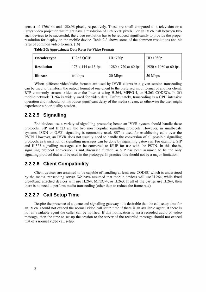
consist of 176x144 and 128x96 pixels, respectively. These are small compared to a television or a larger video projector that might have a resolution of 1280x720 pixels. For an IVVR call between two such devices to be successful, the video resolution has to be reduced significantly to provide the proper resolution for display on the mobile device. Table 2-3 shows some of the common resolutions and bit rates of common video formats. [10]
Table 2-3: Approximate Data Rates for Video Formats
Encoder type H.263 QCIF HD 720p HD 1080p
Resolution 175 x 144 at 15 fps 1280 x 720 at 60 fps 1920 x 1080 at 60 fps
Bit rate 64 kbps 20 Mbps 50 Mbps
When different video/audio formats are used by IVVR clients in a given session transcoding can be used to transform the output format of one client to the preferred input format of another client. RTP commonly streams video over the Internet using H.264, MPEG-4, or H.263 CODECs. In 3G mobile network H.264 is widely used for video data. Unfortunately, transcoding is a CPU intensive operation and it should not introduce significant delay of the media stream, as otherwise the user might experience a poor quality session.
2.2.2.5 Signalling End devices use a variety of signalling protocols; hence an IVVR system should handle these
protocols. SIP and H.323 are the two most popular signalling protocols. However, in small-scale systems, ISDN or Q.931 signalling is commonly used. SS7 is used for establishing calls over the PSTN. However, an IVVR does not usually need to handle the conversion of all possible signalling protocols as translation of signalling messages can be done by signalling gateways. For example, SIP and H.323 signalling messages can be converted to ISUP for use with the PSTN. In this thesis, signalling protocol conversion is not discussed further, as SIP has been assumed to be the only signaling protocol that will be used in the prototype. In practice this should not be a major limitation.
2.2.2.6 Client Compatibility Client devices are assumed to be capable of handling at least one CODEC which is understood
by the media transcoding server. We have assumed that mobile devices will use H.264, while fixed broadband attached devices will use H.264, MPEG-4, or H.263. If all of the parties use H.264, then there is no need to perform media transcoding (other than to reduce the frame rate).
2.2.2.7 Call Setup Time Despite the presence of a queue and signalling gateway, it is desirable that the call setup time for
an IVVR should not exceed the normal video call setup time if there is an available agent. If there is not an available agent the caller can be notified. If this notification is via a recorded audio or video message, then the time to set up the session to the server of the recorded message should not exceed that of a normal video call setup.
9
3 Signalling Protocols Before the communicating parties establish an audio or video communication, they need to
exchange some basic information between themselves. This phase is called a handshake. A handshake is necessary to identify each party, negotiate the audio and video formats each client is capable of handling, and to agree upon the data rate to be used for the combined media streams. The maximum data rates are generally bounded by the link bandwidth available to each party and the available bandwidth on the path from one party to another. A signalling protocol handles all these tasks.
Various signalling protocols are used based on the type of network and the nature of the information transmitted. In this thesis we will not consider the signalling protocols used by the PSTN, but rather will assume that any communication with parties attached to the PSTN will go through signaling and media gateways that are attached to an IP network. For this reason in the remainder of this thesis we will only consider two major signalling protocols, H.323 and SIP. These are described in the following two sections. After the short description of H.323 in the next section we will focus on SIP (as this is used in both the 3GPP’s IP multimedia system (IMS) and in most modern clients attached to various IP networks.
3.1 H.323 The H.323[11] standard was defined by the International Telecommunication Union (ITU). This
is not a single protocol, but rather a large specification defining the possibilities for session establishment using many other protocols, namely H.225 RAS signalling, H.225.0 Call signalling, H.245 Control signalling, RTP (Real Time Protocol), RTCP (Real Time Control Protocol), and H.450, supplementary services and standards for encoding and compression of voice and video. H.323 is a complex protocol often involving unnecessary message exchanges[12]. It was originally designed to establish video conferences, hence identifies the network elements as terminals, gatekeepers, gateways, and multi conferencing units[13].
3.2 Session Initiation Protocol (SIP) SIP was defined by Internet Engineering Task Force(IETF) and is a simpler than H.323 and
tailored more specifically for session establishment and termination[12]. SIP is a text based application layer protocol that can operate over any transport layer protocol. It identifies the participating entities with SIP addresses. These addresses are similar to mail addresses. SIP identifies SIP servers based upon the domain portion of an address. SIP clients can register with one or more SIP domains[14]. SIP uses the Session Description Protocol (SDP) (described in section 3.3) in the SIP payload to exchange information about media encoding formats and end point addresses (including IP address, protocol, and port number). The SIP clients use RTP for data transfer and RTCP for managing data streams. The open source implementations of Asterisk and DiaStar used in this thesis project implement SIP and utilize RTP & RTCP. Additional details of these protocols are provided in the following sections.
3.2.1 SIP Components SIP identifies several different logical components that can be utilized in a SIP implementation.
Each of these components has a specific function. These logical components and their functions are listed in Table 3-1. A single physical device can implement one or more of these elements. Additionally, for scaling multiple physical nodes can also be used to implement each of these logical components. These logical components simplify the task of establishing a communication session.
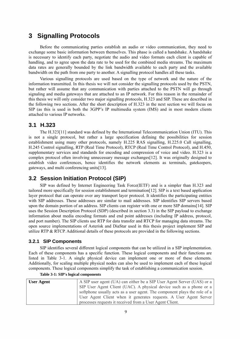
Table 3-1: SIP's logical components
User Agent A SIP user agent (UA) can either be a SIP User Agent Server (UAS) or a SIP User Agent Client (UAC). A physical device such as a phone or a softphone usually acts as a user agent. The component plays the role of a User Agent Client when it generates requests. A User Agent Server processes requests it received from a User Agent Client.
10
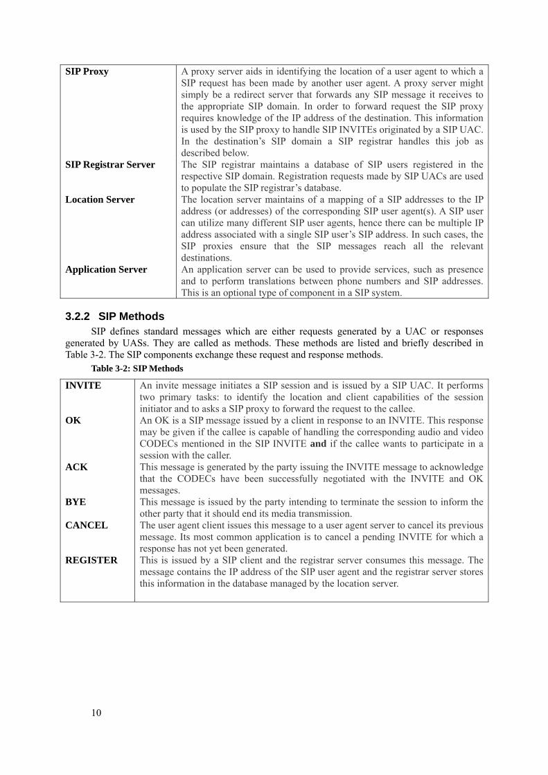
SIP Proxy A proxy server aids in identifying the location of a user agent to which a SIP request has been made by another user agent. A proxy server might simply be a redirect server that forwards any SIP message it receives to the appropriate SIP domain. In order to forward request the SIP proxy requires knowledge of the IP address of the destination. This information is used by the SIP proxy to handle SIP INVITEs originated by a SIP UAC. In the destination’s SIP domain a SIP registrar handles this job as described below.
SIP Registrar Server The SIP registrar maintains a database of SIP users registered in the respective SIP domain. Registration requests made by SIP UACs are used to populate the SIP registrar’s database.
Location Server The location server maintains of a mapping of a SIP addresses to the IP address (or addresses) of the corresponding SIP user agent(s). A SIP user can utilize many different SIP user agents, hence there can be multiple IP address associated with a single SIP user’s SIP address. In such cases, the SIP proxies ensure that the SIP messages reach all the relevant destinations.
Application Server An application server can be used to provide services, such as presence and to perform translations between phone numbers and SIP addresses. This is an optional type of component in a SIP system.
3.2.2 SIP Methods SIP defines standard messages which are either requests generated by a UAC or responses
generated by UASs. They are called as methods. These methods are listed and briefly described in Table 3-2. The SIP components exchange these request and response methods.
Table 3-2: SIP Methods
INVITE An invite message initiates a SIP session and is issued by a SIP UAC. It performs two primary tasks: to identify the location and client capabilities of the session initiator and to asks a SIP proxy to forward the request to the callee.
OK An OK is a SIP message issued by a client in response to an INVITE. This response may be given if the callee is capable of handling the corresponding audio and video CODECs mentioned in the SIP INVITE and if the callee wants to participate in a session with the caller.
ACK This message is generated by the party issuing the INVITE message to acknowledge that the CODECs have been successfully negotiated with the INVITE and OK messages.
BYE This message is issued by the party intending to terminate the session to inform the other party that it should end its media transmission.
CANCEL The user agent client issues this message to a user agent server to cancel its previous message. Its most common application is to cancel a pending INVITE for which a response has not yet been generated.
REGISTER This is issued by a SIP client and the registrar server consumes this message. The message contains the IP address of the SIP user agent and the registrar server stores this information in the database managed by the location server.
11
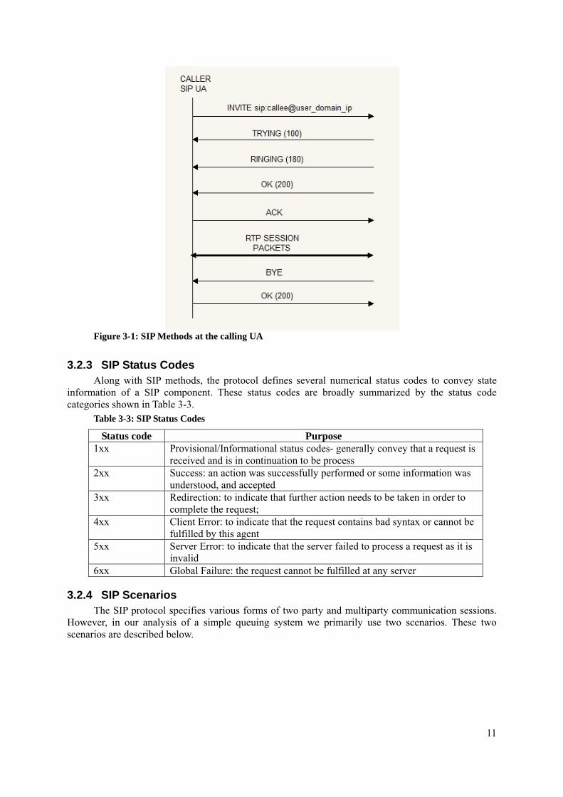
Figure 3-1: SIP Methods at the calling UA
3.2.3 SIP Status Codes Along with SIP methods, the protocol defines several numerical status codes to convey state
information of a SIP component. These status codes are broadly summarized by the status code categories shown in Table 3-3.
Table 3-3: SIP Status Codes
Status code Purpose 1xx Provisional/Informational status codes- generally convey that a request is
received and is in continuation to be process 2xx Success: an action was successfully performed or some information was
understood, and accepted 3xx Redirection: to indicate that further action needs to be taken in order to
complete the request; 4xx Client Error: to indicate that the request contains bad syntax or cannot be
fulfilled by this agent 5xx Server Error: to indicate that the server failed to process a request as it is
invalid 6xx Global Failure: the request cannot be fulfilled at any server
3.2.4 SIP Scenarios The SIP protocol specifies various forms of two party and multiparty communication sessions.
However, in our analysis of a simple queuing system we primarily use two scenarios. These two scenarios are described below.
12
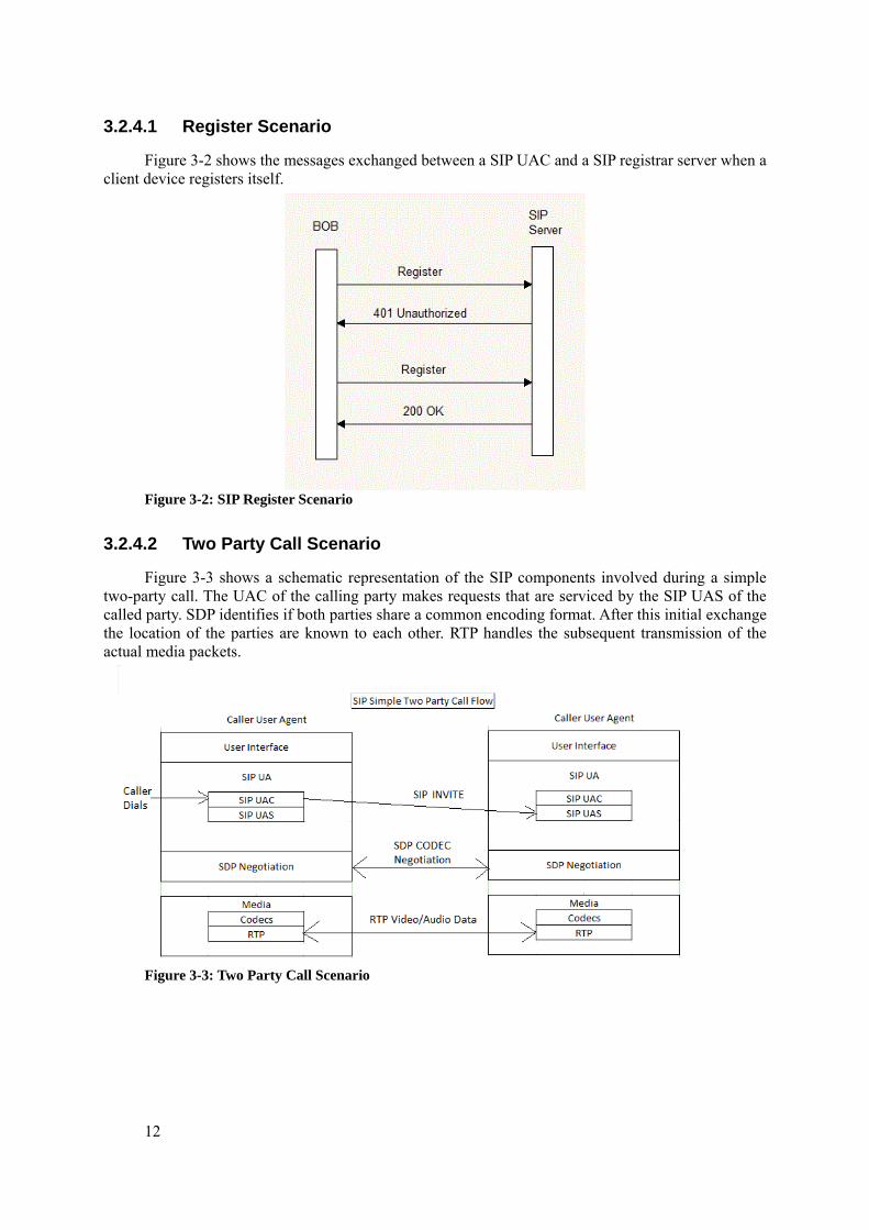
3.2.4.1 Register Scenario
Figure 3-2 shows the messages exchanged between a SIP UAC and a SIP registrar server when a client device registers itself.
Figure 3-2: SIP Register Scenario
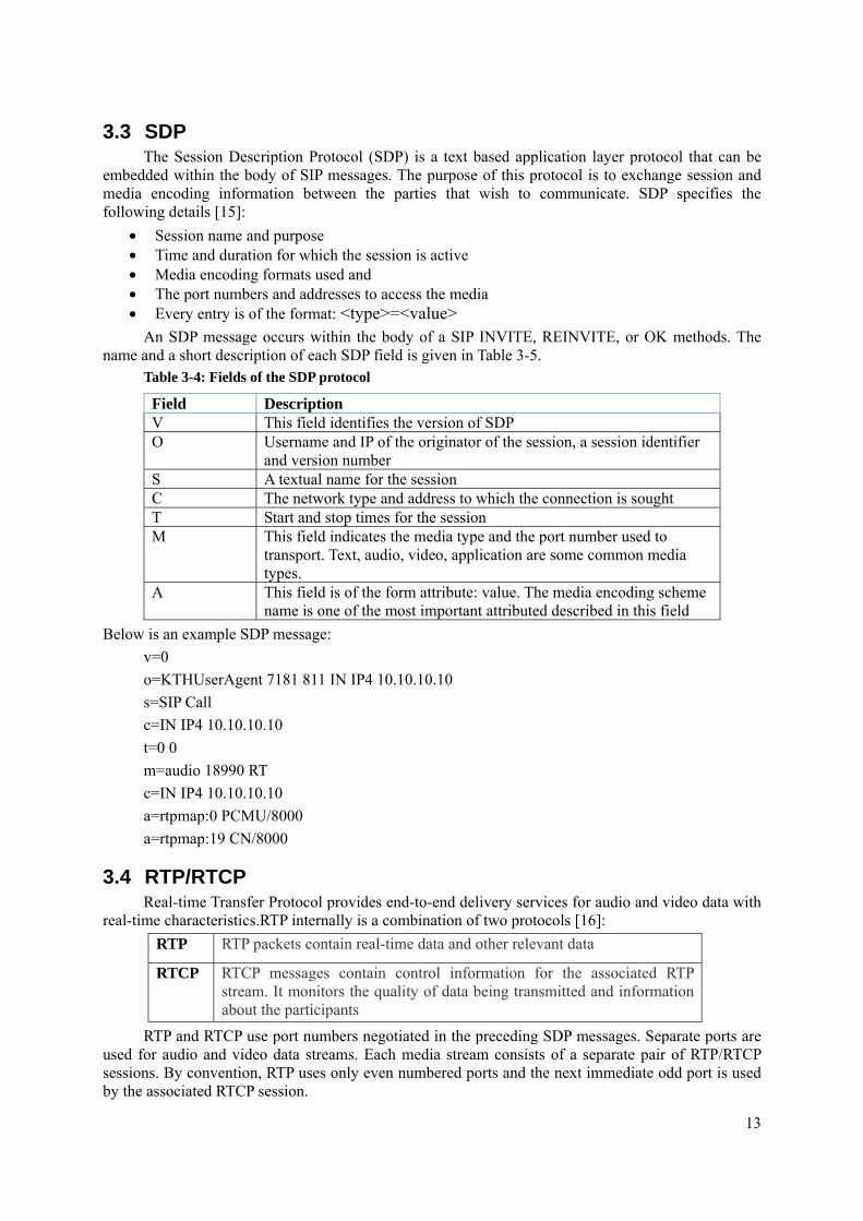
3.2.4.2 Two Party Call Scenario
Figure 3-3 shows a schematic representation of the SIP components involved during a simple two-party call. The UAC of the calling party makes requests that are serviced by the SIP UAS of the called party. SDP identifies if both parties share a common encoding format. After this initial exchange the location of the parties are known to each other. RTP handles the subsequent transmission of the actual media packets.
Figure 3-3: Two Party Call Scenario
13
3.3 SDP The Session Description Protocol (SDP) is a text based application layer protocol that can be
embedded within the body of SIP messages. The purpose of this protocol is to exchange session and media encoding information between the parties that wish to communicate. SDP specifies the following details [15]:
• Session name and purpose • Time and duration for which the session is active • Media encoding formats used and • The port numbers and addresses to access the media • Every entry is of the format: <type>=<value>
An SDP message occurs within the body of a SIP INVITE, REINVITE, or OK methods. The name and a short description of each SDP field is given in Table 3-5.
Table 3-4: Fields of the SDP protocol
Field Description V This field identifies the version of SDP O Username and IP of the originator of the session, a session identifier
and version number S A textual name for the session C The network type and address to which the connection is sought T Start and stop times for the session M This field indicates the media type and the port number used to
transport. Text, audio, video, application are some common media types.
A This field is of the form attribute: value. The media encoding scheme name is one of the most important attributed described in this field
Below is an example SDP message: v=0 o=KTHUserAgent 7181 811 IN IP4 10.10.10.10 s=SIP Call c=IN IP4 10.10.10.10 t=0 0 m=audio 18990 RT c=IN IP4 10.10.10.10 a=rtpmap:0 PCMU/8000 a=rtpmap:19 CN/8000
3.4 RTP/RTCP Real-time Transfer Protocol provides end-to-end delivery services for audio and video data with
real-time characteristics.RTP internally is a combination of two protocols [16]: RTP RTP packets contain real-time data and other relevant data
RTCP RTCP messages contain control information for the associated RTP stream. It monitors the quality of data being transmitted and information about the participants
RTP and RTCP use port numbers negotiated in the preceding SDP messages. Separate ports are used for audio and video data streams. Each media stream consists of a separate pair of RTP/RTCP sessions. By convention, RTP uses only even numbered ports and the next immediate odd port is used by the associated RTCP session.
14
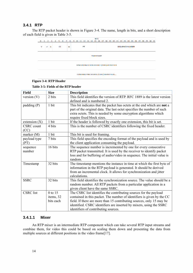
3.4.1 RTP The RTP packet header is shown in Figure 3-4. The name, length in bits, and a short description
of each field is given in Table 3-5.
Figure 3-4: RTP Header
Table 3-5: Fields of the RTP header
Field Size Description version (V) 2 bits This field identifies the version of RTP. RFC 1889 is the latest version
defined and is numbered 2. padding (P) 1 bit This bit indicates that the packet has octets at the end which are not a
part of the original data. The last octet specifies the number of such extra octets. This is needed by some encryption algorithms which require fixed block sizes.
extension (X) 1 bit If the header is followed by exactly one extension, this bit is set. CSRC count (CC)
4 bits This is the number of CSRC identifiers following the fixed header.
marker (M) 1 bit This bit is used for framing. payload type (PT)
7 bits This field specifies the encoding format of the payload and is used by the client application consuming the payload.
sequence number
16 bits The sequence number is incremented by one for every consecutive RTP packet transmitted. It is used by the receiver to identify packet loss and for buffering of audio/video in sequence. The initial value is random.
Timestamp 32 bits The timestamp mentions the instance in time at which the first byte of information in the RTP payload is generated. It should be derived from an incremental clock. It allows for synchronization and jitter calculations.
SSRC 32 bits This field identifies the synchronization source. The value should be a random number. All RTP packets from a particular application in a given client have the same SSRC.
CSRC list 0 to 15 items, 32 bits each
The CSRC list identifies the contributing sources for the payload contained in this packet. The number of identifiers is given by the CC field. If there are more than 15 contributing sources, only 15 may be identified. CSRC identifiers are inserted by mixers, using the SSRC identifiers of contributing sources.
3.4.1.1 Mixer
An RTP mixer is an intermediate RTP component which can take several RTP input streams and combine them, for video this could be based on scaling them down and presenting the data from multiple sources at different positions in the video frame[17].
15
3.4.1.2 Translator
A translator is a RTP component need to transmit RTP packets through firewalls. Firewalls generally block multicast and RTP packets. There could be two translator components, either of them functioning on each side of the firewall. The source translator tunnels RTP packets through a secure connection, while the internal translator extracts the original multicast RTP packets and multicasts them in the internal network.
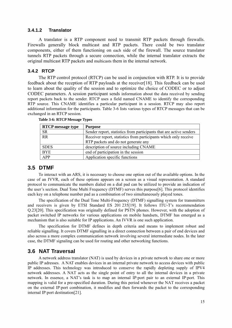
3.4.2 RTCP The RTP control protocol (RTCP) can be used in conjunction with RTP. It is to provide
feedback about the reception of RTP payloads at the receiver[18]. This feedback can be used to learn about the quality of the session and to optimize the choice of CODEC or to adjust CODEC parameters. A session participant sends information about the data received by sending report packets back to the sender. RTCP uses a field named CNAME to identify the corresponding RTP source. This CNAME identifies a particular participant in a session. RTCP may also report additional information for the participants. Table 3-6 lists various types of RTCP messages that can be exchanged in an RTCP session.
Table 3-6: RTCP Message Types
RTCP message type Purpose SR Sender report, statistics from participants that are active senders RR Receiver report, statistics from participants which only receive
RTP packets and do not generate any SDES description of source including CNAME BYE end of participation in the session APP Application specific functions
3.5 DTMF To interact with an ARS, it is necessary to choose one option out of the available options. In the
case of an IVVR, each of these options appears on a screen as a visual representation. A standard protocol to communicate the numbers dialed on a dial pad can be utilized to provide an indication of the user’s section. Dual Tone Multi Frequency (DTMF) serves this purpose[6]. This protocol identifies each key on a telephone number pad as a combination of two simultaneously played tones.
The specification of the Dual Tone Multi-Frequency (DTMF) signalling system for transmitters and receivers is given by ETSI Standard ES 201 235[19]. It follows ITU-T’s recommendation Q.23[20]. This specification was originally defined for PSTN phones. However, with the adoption of packet switched IP networks for various applications on mobile handsets, DTMF has emerged as a mechanism that is also suitable for IP applications. An IVVR is one such application.
The specification for DTMF defines in depth criteria and means to implement robust and reliable signalling. It covers DTMF signalling in a direct connection between a pair of end devices and also across a more complex communication network involving several intermediate nodes. In the later case, the DTMF signaling can be used for routing and other networking functions.
3.6 NAT Traversal A network address translator (NAT) is used by devices in a private network to share one or more
public IP adresses. A NAT enables devices in an internal private network to access devices with public IP addresses. This technology was introduced to conserve the rapidly depleting supply of IPV4 network addresses. A NAT acts as the single point of entry to all the internal devices in a private network. In essence, a NAT’s task is to map an internal IP:port pair to an external IP:port. This mapping is valid for a pre-specified duration. During this period whenever the NAT receives a packet on the external IP:port combination, it modifies and then forwards the packet to the corresponding internal IP:port destination[21].
16
This section introduces NAT terminology and explains only those aspects of NAT which influence the design decisions in construction of an IVVR queue. This knowledge is necessage because when a SIP user agent or a SIP component is located behind a NAT there are some difficulties in the SIP signaling since SIP places IP address and port numbers in the SDP messages.
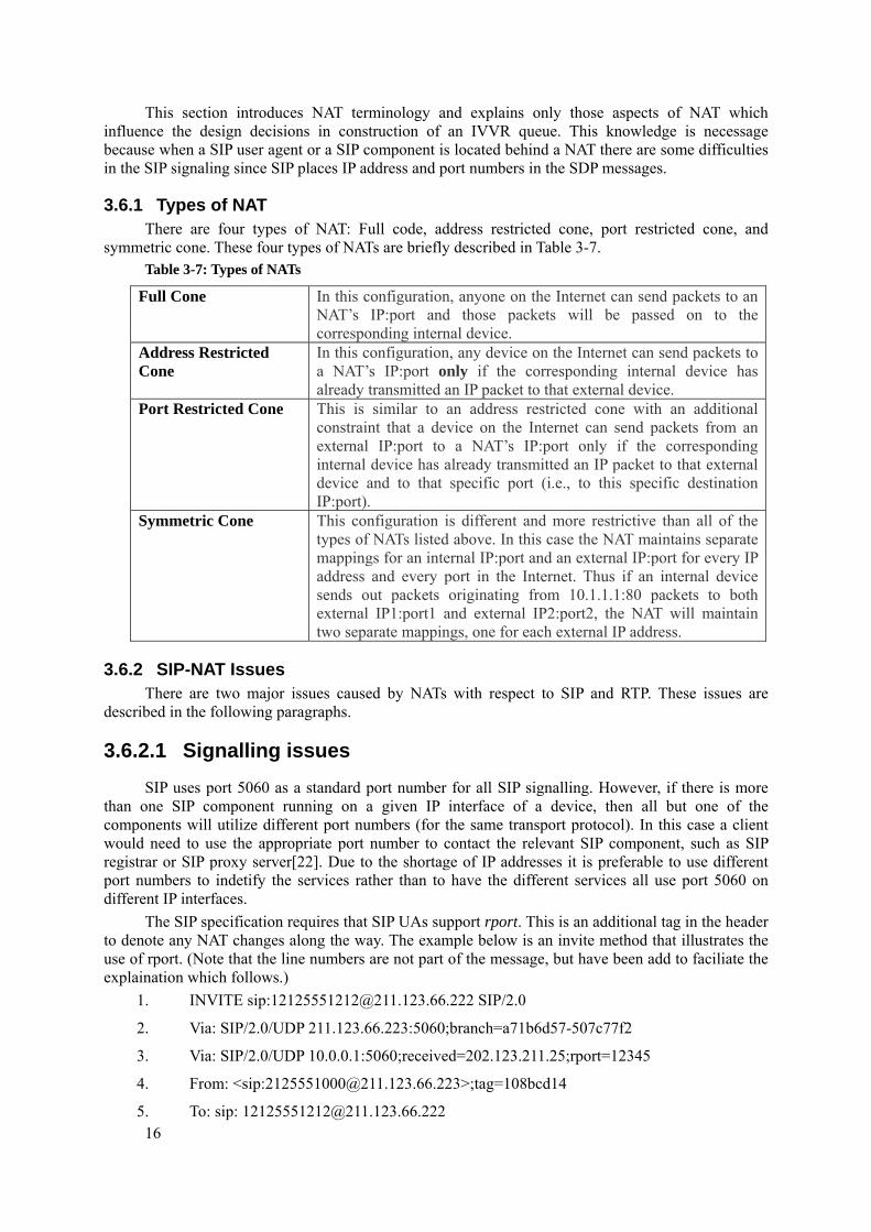
3.6.1 Types of NAT There are four types of NAT: Full code, address restricted cone, port restricted cone, and
symmetric cone. These four types of NATs are briefly described in Table 3-7. Table 3-7: Types of NATs
Full Cone In this configuration, anyone on the Internet can send packets to an NAT’s IP:port and those packets will be passed on to the corresponding internal device.
Address Restricted Cone
In this configuration, any device on the Internet can send packets to a NAT’s IP:port only if the corresponding internal device has already transmitted an IP packet to that external device.
Port Restricted Cone This is similar to an address restricted cone with an additional constraint that a device on the Internet can send packets from an external IP:port to a NAT’s IP:port only if the corresponding internal device has already transmitted an IP packet to that external device and to that specific port (i.e., to this specific destination IP:port).
Symmetric Cone This configuration is different and more restrictive than all of the types of NATs listed above. In this case the NAT maintains separate mappings for an internal IP:port and an external IP:port for every IP address and every port in the Internet. Thus if an internal device sends out packets originating from 10.1.1.1:80 packets to both external IP1:port1 and external IP2:port2, the NAT will maintain two separate mappings, one for each external IP address.
3.6.2 SIP-NAT Issues There are two major issues caused by NATs with respect to SIP and RTP. These issues are
described in the following paragraphs.
3.6.2.1 Signalling issues SIP uses port 5060 as a standard port number for all SIP signalling. However, if there is more
than one SIP component running on a given IP interface of a device, then all but one of the components will utilize different port numbers (for the same transport protocol). In this case a client would need to use the appropriate port number to contact the relevant SIP component, such as SIP registrar or SIP proxy server[22]. Due to the shortage of IP addresses it is preferable to use different port numbers to indetify the services rather than to have the different services all use port 5060 on different IP interfaces.
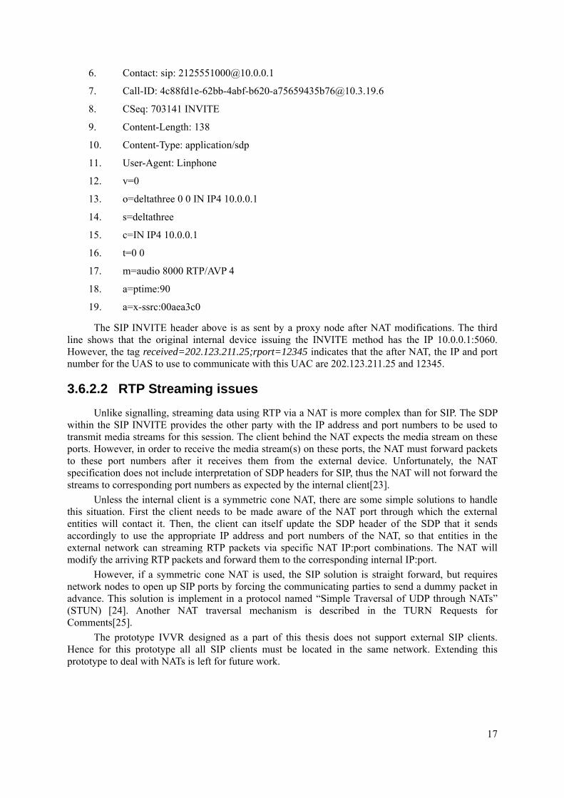
The SIP specification requires that SIP UAs support rport. This is an additional tag in the header to denote any NAT changes along the way. The example below is an invite method that illustrates the use of rport. (Note that the line numbers are not part of the message, but have been add to faciliate the explaination which follows.)
1. INVITE sip:[email protected] SIP/2.0
2. Via: SIP/2.0/UDP 211.123.66.223:5060;branch=a71b6d57-507c77f2
3. Via: SIP/2.0/UDP 10.0.0.1:5060;received=202.123.211.25;rport=12345
4. From: <sip:[email protected]>;tag=108bcd14
5. To: sip: [email protected]
17
6. Contact: sip: [email protected]
7. Call-ID: [email protected]
8. CSeq: 703141 INVITE
9. Content-Length: 138
10. Content-Type: application/sdp
11. User-Agent: Linphone
12. v=0
13. o=deltathree 0 0 IN IP4 10.0.0.1
14. s=deltathree
15. c=IN IP4 10.0.0.1
16. t=0 0
17. m=audio 8000 RTP/AVP 4
18. a=ptime:90
19. a=x-ssrc:00aea3c0
The SIP INVITE header above is as sent by a proxy node after NAT modifications. The third line shows that the original internal device issuing the INVITE method has the IP 10.0.0.1:5060. However, the tag received=202.123.211.25;rport=12345 indicates that the after NAT, the IP and port number for the UAS to use to communicate with this UAC are 202.123.211.25 and 12345.
3.6.2.2 RTP Streaming issues Unlike signalling, streaming data using RTP via a NAT is more complex than for SIP. The SDP
within the SIP INVITE provides the other party with the IP address and port numbers to be used to transmit media streams for this session. The client behind the NAT expects the media stream on these ports. However, in order to receive the media stream(s) on these ports, the NAT must forward packets to these port numbers after it receives them from the external device. Unfortunately, the NAT specification does not include interpretation of SDP headers for SIP, thus the NAT will not forward the streams to corresponding port numbers as expected by the internal client[23].
Unless the internal client is a symmetric cone NAT, there are some simple solutions to handle this situation. First the client needs to be made aware of the NAT port through which the external entities will contact it. Then, the client can itself update the SDP header of the SDP that it sends accordingly to use the appropriate IP address and port numbers of the NAT, so that entities in the external network can streaming RTP packets via specific NAT IP:port combinations. The NAT will modify the arriving RTP packets and forward them to the corresponding internal IP:port.
However, if a symmetric cone NAT is used, the SIP solution is straight forward, but requires network nodes to open up SIP ports by forcing the communicating parties to send a dummy packet in advance. This solution is implement in a protocol named “Simple Traversal of UDP through NATs” (STUN) [24]. Another NAT traversal mechanism is described in the TURN Requests for Comments[25].
The prototype IVVR designed as a part of this thesis does not support external SIP clients. Hence for this prototype all all SIP clients must be located in the same network. Extending this prototype to deal with NATs is left for future work.

19
4 Component Systems This chapter introduces the various software subsystems which have been used to implement the
prototype IVVR system. The description of each system covers only those aspects of the system which are actually relevant to the construction of the prototype.
4.1 Asterisk Asterisk® is an open source PBX and a development environment for various
telecommunication applications programmed in C[26]. It provides abstractions of lower level signalling and session establishment procedures enabling it to manipulate communication sessions in progress. Asterisk understands the standard protocols: SIP, H.323, MGCP[27], and SCCP[28]. It also supports partial interoperability for session transformations between these protocols. It can use the IAX2 protocol [29] to communicate with other Asterisk servers.
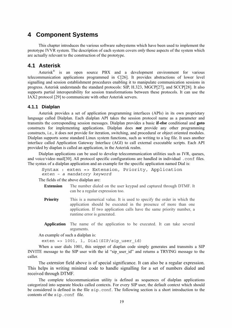
4.1.1 Dialplan Asterisk provides a set of application programming interfaces (APIs) in its own proprietary
language called Dialplan. Each dialplan API takes the session protocol name as a parameter and transmits the corresponding session messages. Dialplan provides a basic if-else conditional and goto constructs for implementing applications. Dialplan does not provide any other programming constructs, i.e., it does not provide for iteration, switching, and procedural or object oriented modules. Dialplan supports some standard Linux system functions, such as writing to a log file. It uses another interface called Application Gateway Interface (AGI) to call external executable scripts. Each API provided by diaplan is called an application, in the Asterisk realm.
Dialplan applications can be used to develop telecommunication utilities such as IVR, queues, and voice/video mail[30]. All protocol specific configurations are handled in individual .conf files. The syntax of a dialplan application and an example for the specific application named Dial is:
Syntax : exten => Extension, Priority, Application exten – a mandatory keyword
The fields of the above dialplan are: Extension The number dialed on the user keypad and captured through DTMF. It
can be a regular expression too.
Priority This is a numerical value. It is used to specify the order in which the application should be executed in the presence of more than one application. If two application calls have the same priority number, a runtime error is generated.
Application The name of the application to be executed. It can take several arguments.
An example of such a dialplan is: exten => 1001, 1, Dial(SIP/sip_user_id)
When a user dials 1001, this snippet of diaplan code simply generates and transmits a SIP INVITE message to the SIP user with the id “sip_user_id” and returns a TRYING message to the caller.
The extension field above is of special significance. It can also be a regular expression. This helps in writing minimal code to handle signalling for a set of numbers dialed and received through DTMF.
The complete telecommunication utility is defined as sequences of dialplan applications categorized into separate blocks called contexts. For every SIP user, the default context which should be considered is defined in the file sip.conf. The following section is a short introduction to the contents of the sip.conf file.
20
4.1.2 SIP Configuration All of Astrisk’s SIP signalling is controlled using a dialplan. However, SIP system specific
configuration details are maintained in a file named sip.conf. Below are the main global entries in this file that are relevant to this thesis. domain=asterisk The sip realm for this installation. A realm
is similar to a mail domain and it aggregates all users authorized to be customers of a particular providers service
bindport = 5060 The port to use for SIP messages, this should be set to 5060 as per RFC3261, but is subject to the discretion of the Asterisk server manager.
register => user[:secret[:authuser]]@host[:port][/extension]
The format for SIP user registration. UACs use this format to contact a specific SIP user.
The file sip.conf also contains the list of SIP users for this particular domain. This is read by Asterisk and loaded into memory while the server is running. A minimal SIP user entry in sip.conf contains all the information relevant to this thesis. Note that the comments follow the line that they are commenting on.
[example_user] ;This is the SIP User Id. callerid="Example UserName" <1002> ;This is the user name for display. The convention is to also specify the number used to dial this user. username=user2 ;This is an optional secondary username secret=pwd2 ;The plaintext password for authentication regexten=1002 ;The number which can be used via DTMF to contact this SIP user dtmfmode=rfc2833 ;The specification under usage for DTMF canreinvite=yes ;Specifies if this SIP user can issue reinvite messages nat=yes ;If the user can be present within a NAT. In this case, SIP NAT rules as per RFC3581 ;are applicable to enable NAT traveral context=users ;The default dialplan context to be used for this SIP user to process the INVITE ;messages he sends to the asterisk server audiocodes=ulaw ;The audio encoding schemes this client can recognize videocodecs=H.263,H.264 ; The video encoding schemes this client can recognize
It is not convenient to list all the SIP users in this file. For this reason, Asterisk provides a feature to run an external script to read the SIP user information into the context of this file at runtime. This feature has the following syntax:
#exec Filepath/FileName
4.2 DiaStar DiaStar is an open source media management and streaming server (although it includes access
to proprietary functions of Dialogic®)[31]. DiaStar is coded in C and embedded in a customized version of the Community ENTerprise Operating System (CentOS)[32]. DiaStar is available for
21
academic and commercial usage for a limited period, after which a paid license is required.The application is available as an installable operating system. It can perform the following operations:
• SIP and H.323 signalling; • Conversion of video media from one CODEC to other between H.232, H.264, and MPEG; • Conversion of audio media between PCMa (alaw), PCMu (μlaw), G.722, G.729, and vox; • Stream static image, audio, and video files; • Interpreting DTMF signals; • Transizing of video frames and partial video conference session management; and • Establish video conferences, whose identification and layout is statically configured.
In order to configure DiaStar to function in conjunction with Asterisk, the IP address and SIP port of Asterisk must be configured in a DiaStar configuration file. A plugin named chan_woomera should be compiled and installed on the Asterisk server[33]. This plugin can interpret signalling messages in a protocol named woomera, which is used by DiaStar to communicate with Asterisk. DiaStar can also accept SIP signalling messages and communicate with Asterisk by converting them into equivalent H.323 signals. However, DiaStar does not use native H.323, but rather tunnels them in the woomera protocol. By default, DiaStar uses destination port 42420 to connect to Asterisk using woomera.
DiaStar cannot handle NAT traversal of SIP signals and also cannot communicate with Asterisk if it is not present in the same LAN. Both Asterisk and DiaStar cannot be run on a single system due to the fact that they each expect to list to the same SIP port number. While it is possible to configure Asterisk to use a different port number, the study carried out in this thesisproject assumes that these two servers are located on different machines.
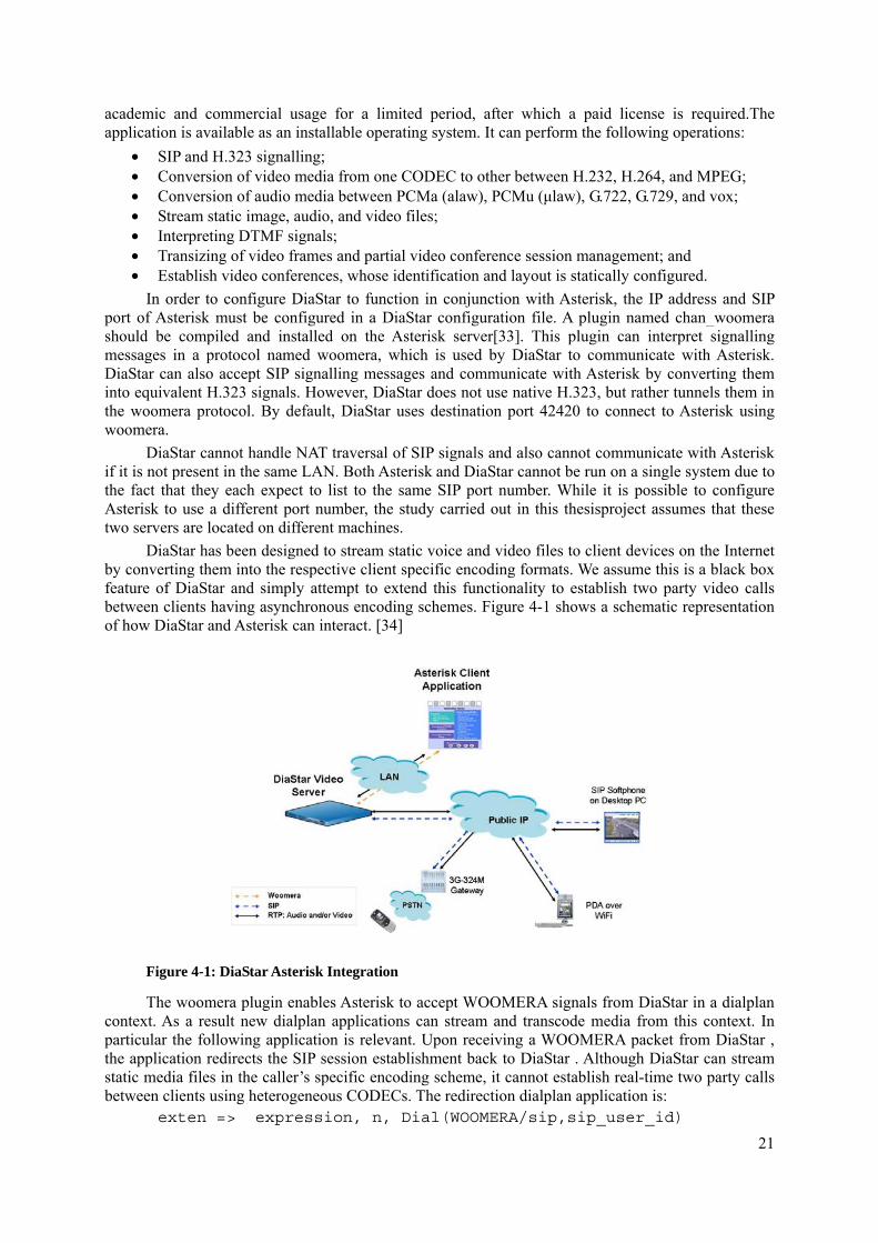
DiaStar has been designed to stream static voice and video files to client devices on the Internet by converting them into the respective client specific encoding formats. We assume this is a black box feature of DiaStar and simply attempt to extend this functionality to establish two party video calls between clients having asynchronous encoding schemes. Figure 4-1 shows a schematic representation of how DiaStar and Asterisk can interact. [34]
Figure 4-1: DiaStar Asterisk Integration
The woomera plugin enables Asterisk to accept WOOMERA signals from DiaStar in a dialplan context. As a result new dialplan applications can stream and transcode media from this context. In particular the following application is relevant. Upon receiving a WOOMERA packet from DiaStar , the application redirects the SIP session establishment back to DiaStar . Although DiaStar can stream static media files in the caller’s specific encoding scheme, it cannot establish real-time two party calls between clients using heterogeneous CODECs. The redirection dialplan application is:
exten => expression, n, Dial(WOOMERA/sip,sip_user_id)
22
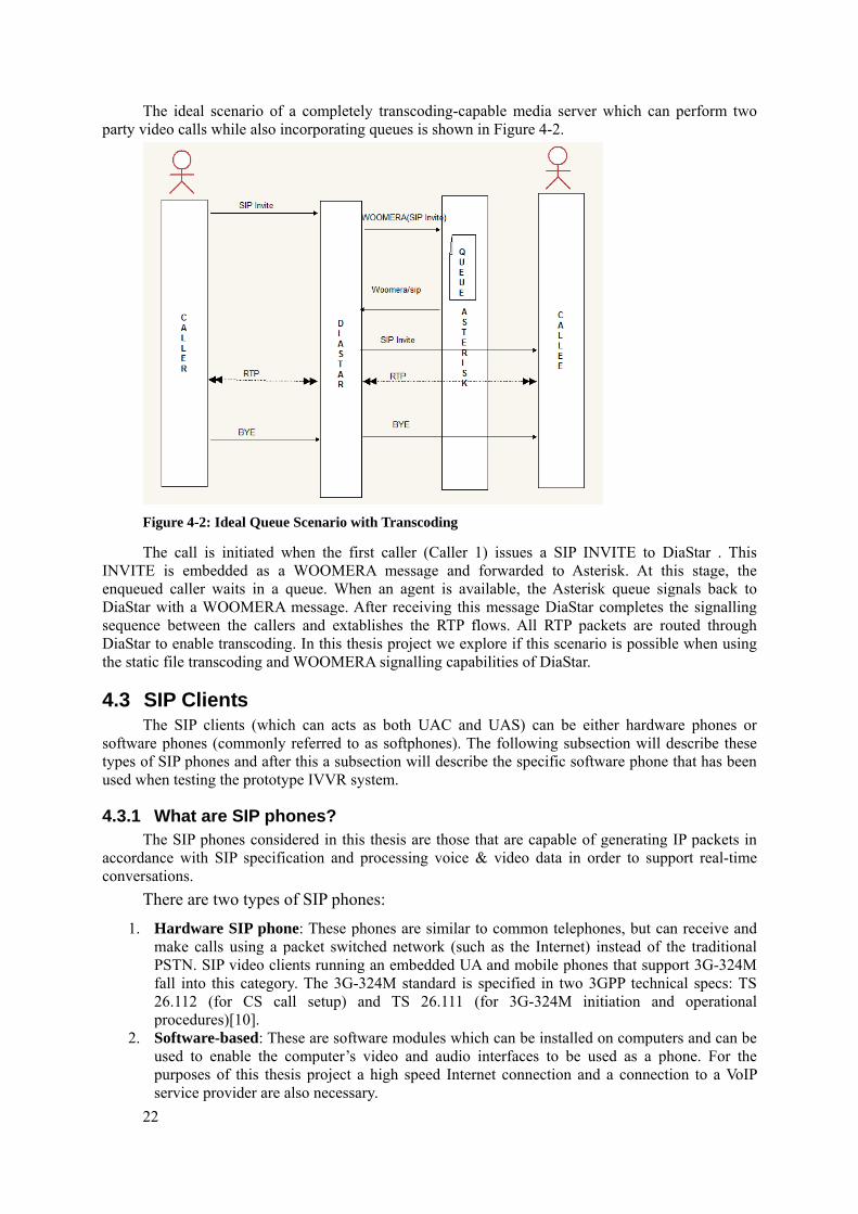
The ideal scenario of a completely transcoding-capable media server which can perform two party video calls while also incorporating queues is shown in Figure 4-2.
Figure 4-2: Ideal Queue Scenario with Transcoding
The call is initiated when the first caller (Caller 1) issues a SIP INVITE to DiaStar . This INVITE is embedded as a WOOMERA message and forwarded to Asterisk. At this stage, the enqueued caller waits in a queue. When an agent is available, the Asterisk queue signals back to DiaStar with a WOOMERA message. After receiving this message DiaStar completes the signalling sequence between the callers and extablishes the RTP flows. All RTP packets are routed through DiaStar to enable transcoding. In this thesis project we explore if this scenario is possible when using the static file transcoding and WOOMERA signalling capabilities of DiaStar.
4.3 SIP Clients The SIP clients (which can acts as both UAC and UAS) can be either hardware phones or
software phones (commonly referred to as softphones). The following subsection will describe these types of SIP phones and after this a subsection will describe the specific software phone that has been used when testing the prototype IVVR system.
4.3.1 What are SIP phones? The SIP phones considered in this thesis are those that are capable of generating IP packets in
accordance with SIP specification and processing voice & video data in order to support real-time conversations.
There are two types of SIP phones:
1. Hardware SIP phone: These phones are similar to common telephones, but can receive and make calls using a packet switched network (such as the Internet) instead of the traditional PSTN. SIP video clients running an embedded UA and mobile phones that support 3G-324M fall into this category. The 3G-324M standard is specified in two 3GPP technical specs: TS 26.112 (for CS call setup) and TS 26.111 (for 3G-324M initiation and operational procedures)[10].
2. Software-based: These are software modules which can be installed on computers and can be used to enable the computer’s video and audio interfaces to be used as a phone. For the purposes of this thesis project a high speed Internet connection and a connection to a VoIP service provider are also necessary.
23
SIP phones have different abilities to process video streams and display them. This processing depends on the processing power of the device’s processors (the system can utilize both a central processor and one or more additional processors, the later can include special purpose signal processors and graphics processors), the amount of buffer memory available, audio & video buffering mechanisms, and the features of the local audio & video processing software. Although there are several universal standards to implement both hardware and software, they are incomplete in some aspects and there are a lot of different types of SIP phones. For rendering a streaming video, using a complex buffer management algorithm interferes with the ability to generate frames at a constant rate. There is a need to compromise between latency and optimally managing the buffer memory. Streaming video data at the appropriate frame size and resolution for the destination works better than resizing the video in a video client with limited capabilities, hence the need for a node elsewhere in the network to do transcoding.
4.3.2 Linphone Linphone[35] is a VoIP softphone. This specific VoIP softphone has been used in the
development of the prototype application during this thesis project. Linphone is a open-source VoIP program that uses SIP for signalling. We have selected Linphone for this project because:
• Linphone works with any SIP VoIP operator. • Linphone is an open-source software and is available for desktop computers: Linux, Windows,
MacOSX, and for mobile phones: Android, iPhone, Blackberry. • Linphone uses GTK+ for the graphical user interface. On Linux Linphone can also be run as a
console-mode application .

25
5 Methods This chapter explains the realization of a prototype IVVR queue system. It uses only SIP for
signalling and assumes a uniform encoding scheme for all the calls. The chapter also describes several design alternatives and the actual alternative chosen for implementation. It provides the rationale for deciding on the particular choice of each alternative.
An attempt to integrate a media translation server was made, but could not be realized. A description of the technical concepts to integrate transcoding with Asterisk is given. A conceptual analysis of this integration is also provided in section 5.2.
5.1 Queue Architecture Realization of a simple IVVR queue includes the tasks of controlling the SIP signalling
methods, configuring the CODEC information of the various SIP agents, creation of SIP accounts at the SIP registry, data modeling for agent/caller state management, and scripting to perform the required database operations.
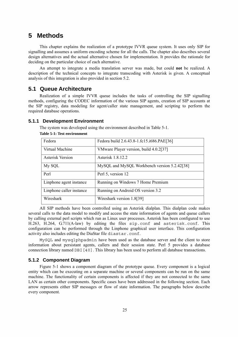
5.1.1 Development Environment The system was developed using the environment described in Table 5-1. Table 5-1: Test environment
Fedora Fedora build 2.6.43.8-1.fc15.i686.PAE[36]
Virtual Machine VMware Player version, build 4.0.2[37]
Asterisk Version Asterisk 1.8.12.2
My SQL MySQL and MySQL Workbench version 5.2.42[38]
Perl Perl 5, version 12
Linphone agent instance Running on Windows 7 Home Premium
Linphone caller instance Running on Android OS version 3.2
Wireshark Wireshark version 1.8[39]
All SIP methods have been controlled using an Asterisk dialplan. This dialplan code makes several calls to the data model to modify and access the state information of agents and queue callers by calling external perl scripts which run as Linux user processes. Asterisk has been configured to use H.263, H.264, G.711(A-law) by editing the files sip.conf and asterisk.conf. This configuration can be performed through the Linphone graphical user interface. This configuration activity also includes editing the DiaStar file diastar.conf.
MySQL and mysqlphpadmin have been used as the database server and the client to store information about persistant agents, callers and their session state. Perl 5 provides a database connection library named DBI[40]. This library has been used to perform all database transactions.
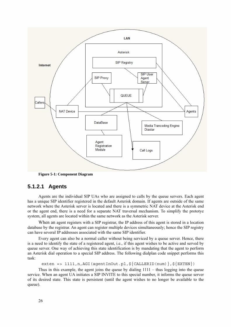
5.1.2 Component Diagram Figure 5-1 shows a component diagram of the prototype queue. Every component is a logical
entity which can be executing on a separate machine or several components can be run on the same machine. The functionality of certain components is affected if they are not connected to the same LAN as certain other components. Specific cases have been addressed in the following section. Each arrow represents either SIP messages or flow of state information. The paragraphs below describe every component.
26
Figure 5-1: Component Diagram
5.1.2.1 Agents Agents are the individual SIP UAs who are assigned to calls by the queue servers. Each agent
has a unique SIP identifier registered in the default Asterisk domain. If agents are outside of the same network where the Asterisk server is located and there is a symmetric NAT device at the Asterisk end or the agent end, there is a need for a separate NAT traversal mechanism. To simplify the prototye system, all agents are located within the same network as the Asterisk server.
When an agent registers with a SIP registrar, the IP address of this agent is stored in a location database by the registrar. An agent can register multiple devices simultaneously; hence the SIP registry can have several IP addresses associated with the same SIP identifier.
Every agent can also be a normal caller without being serviced by a queue server. Hence, there is a need to identify the state of a registered agent, i.e., if this agent wishes to be active and served by queue server. One way of achieving this state identification is by mandating that the agent to perform an Asterisk dial operation to a special SIP address. The following dialplan code snippet performs this task:
exten => 1111,n,AGI(agentInOut.pl,${CALLERID(num)},${EXTEN})
Thus in this example, the agent joins the queue by dialing 1111 – thus logging into the queue service. When an agent UA initiates a SIP INVITE to this special number, it informs the queue server of its desired state. This state is persistent (until the agent wishes to no longer be available to the queue).
27
For every such agent login event, the following information is stored in a MySQL database: Agent id The agent’s ID can be obtained from the INVITE message sent from
the agent’s UAC to the registry. Agent status The agent’s status indicates whether the agent is free or occupied in a
SIP session. By default, it is set to free. Unique_id A unique number is generated by Asterisk to represent a session
which is in progress. By default this value is set to a null. This field is updated for the corresponding agent when a session is established and the agent is involved in a SIP session.
Agent logout is performed in a similar manner. The agent calls the same number (“1111”) a second time to indicate that he or she no longer wishes to be available to the queue server. Upon receiving an INVITE for this special number, the corresponding agent record is deleted.
5.1.2.2 Callers Callers are the SIP UACs situated outside the Asterisk network. In the most general scenarios,
these callers are locates behind NATs. However, to simplify the implementation and evaluation of prototype, all callers are assumed to be in the same network as the Asterisk server. During the design, implementation, and evaluation of the queue system, Linphone clients installed on my laptop and my Android phone were used to simulate callers.
Whenever a caller is connected to an agent servicing a queue, the following details are recorded in the database: unique_id VARCHAR(100) This is the unique channel id. It is generated by asterisk for every SIP
call upon receiving an INVITE. epoch INT UNSIGNED The time instant at which the call is established. It is used to sort and
enqueue callers as per their arrival time and hence implement the logical queue.
queue_num VARCHAR(3) The queue identifier in case there are multiple queues. In this work, only one queue has been simulated
caller_id VARCHAR(100) The SIP identifier of the caller These details help in managing the queue’s free-agent status information. Only free agents are
eligible to be assigned to a new caller.
5.1.2.3 Agent Registration Module Before agents can issue SIP register methods to Asterisk, it is necessary to load their
corresponding SIP IDs into the system. This was performed by calling a perl script from Asterisk to read the SIP user information from the database. The database was populated using another perl script to generate agent information. The details below are tracked in the schema and are used at various points in this work: agent_sip_id VARCHAR(100) The sip identifier of the agent secret VARCHAR(100) The password used by the agent to register ext_num INT UNSIGNED Extension number, upon which the agent can be reached display_name VARCHAR(100) The visual display name of the agent nat VARCHAR(1) Indicates whether the agent is behind a NAT device. The value is
assumed to be no for all the agents throughout this thesis project. video_codecs VARCHAR(100) The video CODECs supported by the agent device. This value is
H.263 or H.264 throughout this thesis project. audio_codecs VARCHAR(100) The audio CODECs supported by the agent device. This value is
PCMA (alaw) or PCMu (μlaw) throughout this thesis project.
28
5.1.2.4 Database The MySQL database implantation was used to store all active and static SIP user and session
information. MySQL was chosen since its is an open source implementation. Additionally, MySQL supports fine grained transaction isolation levels. The MySQL-phpmyadmin client was used since it is shipped along with MySQL.
5.1.2.5 Logging System The logging system is an extension to the queuing system. The information recorded by this
looging system could be used for billing purposes in a commercial system. While the prototype is not a commercial system, the logging system was valuable during the evaluation of this prototype as it captures accurate queuing statistics with respect to call duration, queue length, and agent productivity. Certain log information is captured during the following events:
1. A new call into the queue 2. Successful call establishment with an agent 3. An caller abandoning the queue without availing the queue service 4. Teardown of an established call.
For each of these events the following details are captured: unique_id VARCHAR(100) The unique identifier of the SIP call epoch VARCHAR(20) The time instant when the call was made event VARCHAR(50) Is one INVITE, ACCEPT, BYE and ABANDON detail VARCHAR(50) Simply description of the event queue_num VARCHAR(2) The queue identifier in case of multiple queues
5.1.2.6 Asterisk The SIP registry, proxy, user agent server, and the queue functions are running as separate
system processes in the Asterisk environment. The queue is the central focus in this thesis project. A flow chart of the queue design is provided in section 5.1.5.
5.1.2.7 Media transcoding engine During this thesis project I have attempted to transcode video data using DiaStar in order to
enable calls supporting asynchronous video CODECs. A study of various DiaStar-Asterisk integration scenarios was necessary in order to achieve this. Single or multiple instances of DiaStar can be integrated with one Asterisk instance. A theoretical study of configuration of these systems was performed, but none of these configurations could be successfully realized due to several configuration issues faced while establishing a functional DiaStar system. The following systemswere used to install a DiaStar system. A short description is given for why the system failed to run.
1) Acer 4736Z Laptop : DiaStar’s ISO installer halts during the installation procedure infinitely without any response.
2) VMWare Player running on a Compaq CQ57 Laptop : CentOS embedded with the DiaStar system does uses an encryption scheme known as SELINUX in the kernel which requires support from hardware. However VMWare Player does not provide the hardware simulation support for systems using SELINUX
3) Oracle VirtualBox[41] running on a Compaq CQ57 Laptop : The DiaStar server installation procedure successfully ran on this virtual machine. However, the DiaStar server thus installed is not capable of successfully communicating with the network interface card of the host operating system.
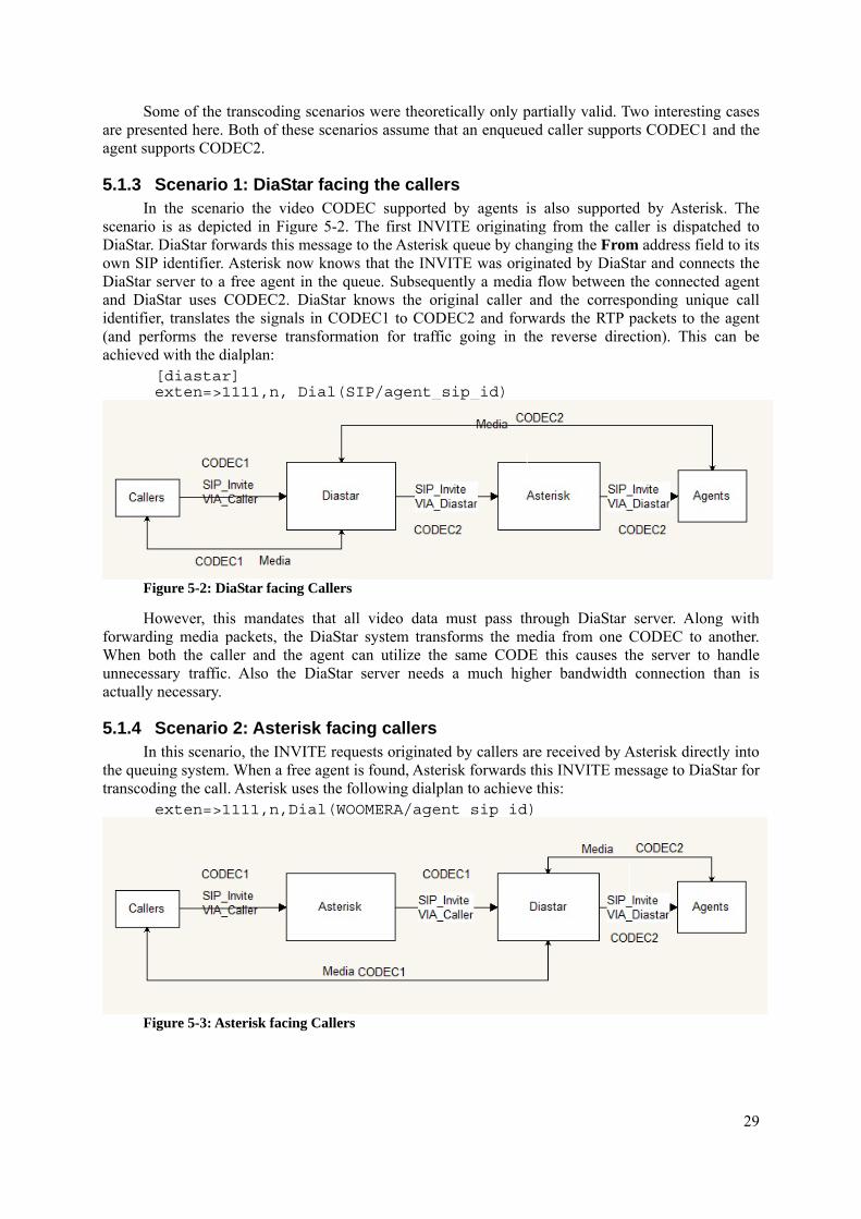
29
Some of the transcoding scenarios were theoretically only partially valid. Two interesting cases are presented here. Both of these scenarios assume that an enqueued caller supports CODEC1 and the agent supports CODEC2.
5.1.3 Scenario 1: DiaStar facing the callers In the scenario the video CODEC supported by agents is also supported by Asterisk. The
scenario is as depicted in Figure 5-2. The first INVITE originating from the caller is dispatched to DiaStar. DiaStar forwards this message to the Asterisk queue by changing the From address field to its own SIP identifier. Asterisk now knows that the INVITE was originated by DiaStar and connects the DiaStar server to a free agent in the queue. Subsequently a media flow between the connected agent and DiaStar uses CODEC2. DiaStar knows the original caller and the corresponding unique call identifier, translates the signals in CODEC1 to CODEC2 and forwards the RTP packets to the agent (and performs the reverse transformation for traffic going in the reverse direction). This can be achieved with the dialplan:
[diastar] exten=>1111,n, Dial(SIP/agent_sip_id)
Figure 5-2: DiaStar facing Callers
However, this mandates that all video data must pass through DiaStar server. Along with forwarding media packets, the DiaStar system transforms the media from one CODEC to another. When both the caller and the agent can utilize the same CODE this causes the server to handle unnecessary traffic. Also the DiaStar server needs a much higher bandwidth connection than is actually necessary.
5.1.4 Scenario 2: Asterisk facing callers In this scenario, the INVITE requests originated by callers are received by Asterisk directly into
the queuing system. When a free agent is found, Asterisk forwards this INVITE message to DiaStar for transcoding the call. Asterisk uses the following dialplan to achieve this:
exten=>1111,n,Dial(WOOMERA/agent_sip_id)
Figure 5-3: Asterisk facing Callers
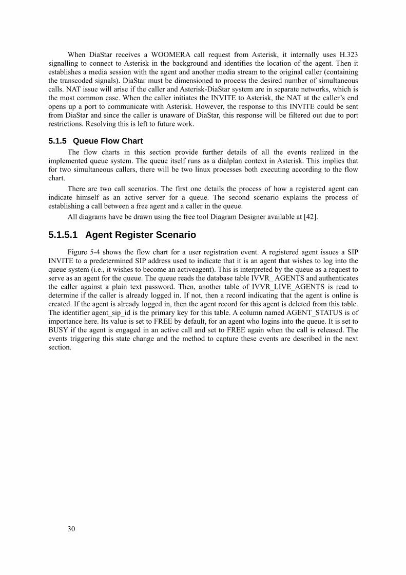
30
When DiaStar receives a WOOMERA call request from Asterisk, it internally uses H.323 signalling to connect to Asterisk in the background and identifies the location of the agent. Then it establishes a media session with the agent and another media stream to the original caller (containing the transcoded signals). DiaStar must be dimensioned to process the desired number of simultaneous calls. NAT issue will arise if the caller and Asterisk-DiaStar system are in separate networks, which is the most common case. When the caller initiates the INVITE to Asterisk, the NAT at the caller’s end opens up a port to communicate with Asterisk. However, the response to this INVITE could be sent from DiaStar and since the caller is unaware of DiaStar, this response will be filtered out due to port restrictions. Resolving this is left to future work.
5.1.5 Queue Flow Chart The flow charts in this section provide further details of all the events realized in the
implemented queue system. The queue itself runs as a dialplan context in Asterisk. This implies that for two simultaneous callers, there will be two linux processes both executing according to the flow chart.
There are two call scenarios. The first one details the process of how a registered agent can indicate himself as an active server for a queue. The second scenario explains the process of establishing a call between a free agent and a caller in the queue.
All diagrams have be drawn using the free tool Diagram Designer available at [42].
5.1.5.1 Agent Register Scenario Figure 5-4 shows the flow chart for a user registration event. A registered agent issues a SIP
INVITE to a predetermined SIP address used to indicate that it is an agent that wishes to log into the queue system (i.e., it wishes to become an activeagent). This is interpreted by the queue as a request to serve as an agent for the queue. The queue reads the database table IVVR_ AGENTS and authenticates the caller against a plain text password. Then, another table of IVVR_LIVE_AGENTS is read to determine if the caller is already logged in. If not, then a record indicating that the agent is online is created. If the agent is already logged in, then the agent record for this agent is deleted from this table. The identifier agent_sip_id is the primary key for this table. A column named AGENT_STATUS is of importance here. Its value is set to FREE by default, for an agent who logins into the queue. It is set to BUSY if the agent is engaged in an active call and set to FREE again when the call is released. The events triggering this state change and the method to capture these events are described in the next section.
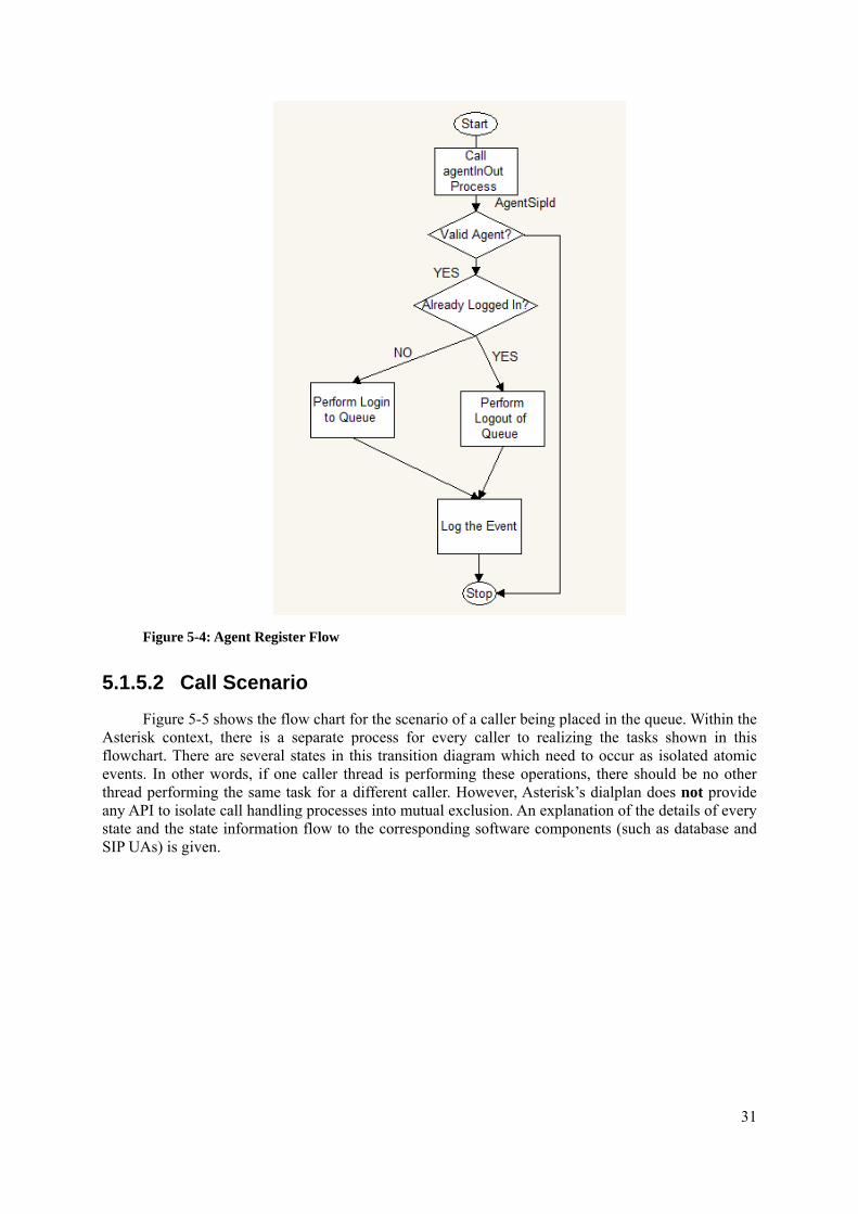
31
Figure 5-4: Agent Register Flow
5.1.5.2 Call Scenario Figure 5-5 shows the flow chart for the scenario of a caller being placed in the queue. Within the
Asterisk context, there is a separate process for every caller to realizing the tasks shown in this flowchart. There are several states in this transition diagram which need to occur as isolated atomic events. In other words, if one caller thread is performing these operations, there should be no other thread performing the same task for a different caller. However, Asterisk’s dialplan does not provide any API to isolate call handling processes into mutual exclusion. An explanation of the details of every state and the state information flow to the corresponding software components (such as database and SIP UAs) is given.
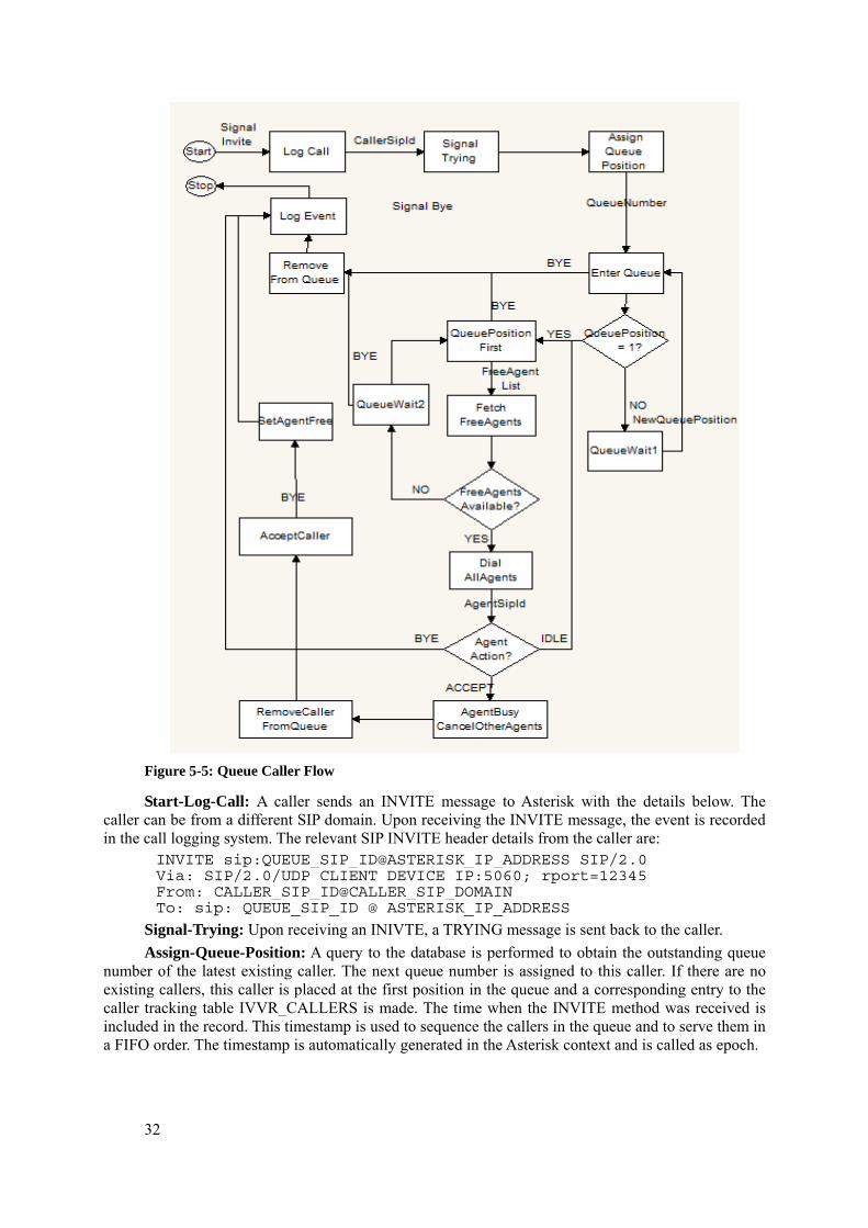
32
Figure 5-5: Queue Caller Flow
Start-Log-Call: A caller sends an INVITE message to Asterisk with the details below. The caller can be from a different SIP domain. Upon receiving the INVITE message, the event is recorded in the call logging system. The relevant SIP INVITE header details from the caller are:
INVITE sip:QUEUE_SIP_ID@ASTERISK_IP_ADDRESS SIP/2.0 Via: SIP/2.0/UDP CLIENT_DEVICE_IP:5060; rport=12345 From: CALLER_SIP_ID@CALLER_SIP_DOMAIN To: sip: QUEUE_SIP_ID @ ASTERISK_IP_ADDRESS
Signal-Trying: Upon receiving an INIVTE, a TRYING message is sent back to the caller. Assign-Queue-Position: A query to the database is performed to obtain the outstanding queue
number of the latest existing caller. The next queue number is assigned to this caller. If there are no existing callers, this caller is placed at the first position in the queue and a corresponding entry to the caller tracking table IVVR_CALLERS is made. The time when the INVITE method was received is included in the record. This timestamp is used to sequence the callers in the queue and to serve them in a FIFO order. The timestamp is automatically generated in the Asterisk context and is called as epoch.
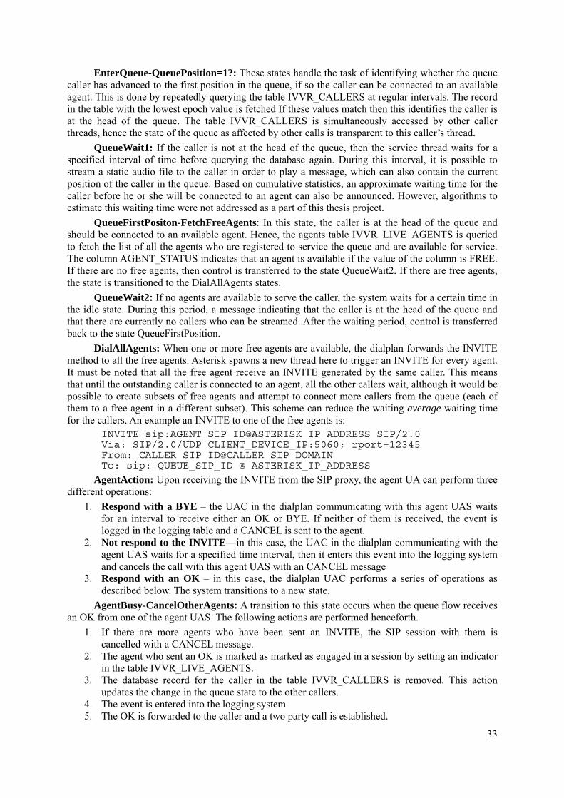
33
EnterQueue-QueuePosition=1?: These states handle the task of identifying whether the queue caller has advanced to the first position in the queue, if so the caller can be connected to an available agent. This is done by repeatedly querying the table IVVR_CALLERS at regular intervals. The record in the table with the lowest epoch value is fetched If these values match then this identifies the caller is at the head of the queue. The table IVVR_CALLERS is simultaneously accessed by other caller threads, hence the state of the queue as affected by other calls is transparent to this caller’s thread.
QueueWait1: If the caller is not at the head of the queue, then the service thread waits for a specified interval of time before querying the database again. During this interval, it is possible to stream a static audio file to the caller in order to play a message, which can also contain the current position of the caller in the queue. Based on cumulative statistics, an approximate waiting time for the caller before he or she will be connected to an agent can also be announced. However, algorithms to estimate this waiting time were not addressed as a part of this thesis project.
QueueFirstPositon-FetchFreeAgents: In this state, the caller is at the head of the queue and should be connected to an available agent. Hence, the agents table IVVR_LIVE_AGENTS is queried to fetch the list of all the agents who are registered to service the queue and are available for service. The column AGENT_STATUS indicates that an agent is available if the value of the column is FREE. If there are no free agents, then control is transferred to the state QueueWait2. If there are free agents, the state is transitioned to the DialAllAgents states.
QueueWait2: If no agents are available to serve the caller, the system waits for a certain time in the idle state. During this period, a message indicating that the caller is at the head of the queue and that there are currently no callers who can be streamed. After the waiting period, control is transferred back to the state QueueFirstPosition.
DialAllAgents: When one or more free agents are available, the dialplan forwards the INVITE method to all the free agents. Asterisk spawns a new thread here to trigger an INVITE for every agent. It must be noted that all the free agent receive an INVITE generated by the same caller. This means that until the outstanding caller is connected to an agent, all the other callers wait, although it would be possible to create subsets of free agents and attempt to connect more callers from the queue (each of them to a free agent in a different subset). This scheme can reduce the waiting average waiting time for the callers. An example an INVITE to one of the free agents is:
INVITE sip:AGENT_SIP_ID@ASTERISK_IP_ADDRESS SIP/2.0 Via: SIP/2.0/UDP CLIENT_DEVICE_IP:5060; rport=12345 From: CALLER_SIP_ID@CALLER_SIP_DOMAIN To: sip: QUEUE_SIP_ID @ ASTERISK_IP_ADDRESS
AgentAction: Upon receiving the INVITE from the SIP proxy, the agent UA can perform three different operations:
1. Respond with a BYE – the UAC in the dialplan communicating with this agent UAS waits for an interval to receive either an OK or BYE. If neither of them is received, the event is logged in the logging table and a CANCEL is sent to the agent.
2. Not respond to the INVITE—in this case, the UAC in the dialplan communicating with the agent UAS waits for a specified time interval, then it enters this event into the logging system and cancels the call with this agent UAS with an CANCEL message
3. Respond with an OK – in this case, the dialplan UAC performs a series of operations as described below. The system transitions to a new state.
AgentBusy-CancelOtherAgents: A transition to this state occurs when the queue flow receives an OK from one of the agent UAS. The following actions are performed henceforth.
1. If there are more agents who have been sent an INVITE, the SIP session with them is cancelled with a CANCEL message.
2. The agent who sent an OK is marked as marked as engaged in a session by setting an indicator in the table IVVR_LIVE_AGENTS.
3. The database record for the caller in the table IVVR_CALLERS is removed. This action updates the change in the queue state to the other callers.
4. The event is entered into the logging system 5. The OK is forwarded to the caller and a two party call is established.
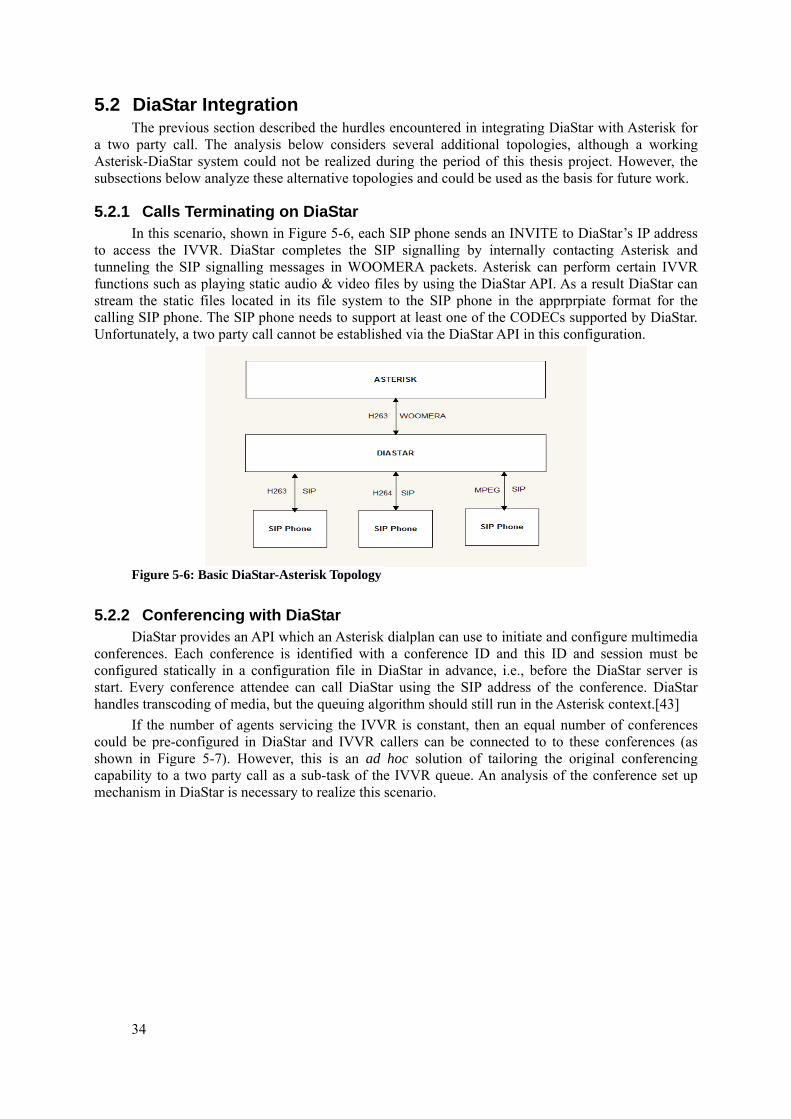
34
5.2 DiaStar Integration The previous section described the hurdles encountered in integrating DiaStar with Asterisk for
a two party call. The analysis below considers several additional topologies, although a working Asterisk-DiaStar system could not be realized during the period of this thesis project. However, the subsections below analyze these alternative topologies and could be used as the basis for future work.
5.2.1 Calls Terminating on DiaStar In this scenario, shown in Figure 5-6, each SIP phone sends an INVITE to DiaStar’s IP address
to access the IVVR. DiaStar completes the SIP signalling by internally contacting Asterisk and tunneling the SIP signalling messages in WOOMERA packets. Asterisk can perform certain IVVR functions such as playing static audio & video files by using the DiaStar API. As a result DiaStar can stream the static files located in its file system to the SIP phone in the apprprpiate format for the calling SIP phone. The SIP phone needs to support at least one of the CODECs supported by DiaStar. Unfortunately, a two party call cannot be established via the DiaStar API in this configuration.
Figure 5-6: Basic DiaStar-Asterisk Topology
5.2.2 Conferencing with DiaStar DiaStar provides an API which an Asterisk dialplan can use to initiate and configure multimedia
conferences. Each conference is identified with a conference ID and this ID and session must be configured statically in a configuration file in DiaStar in advance, i.e., before the DiaStar server is start. Every conference attendee can call DiaStar using the SIP address of the conference. DiaStar handles transcoding of media, but the queuing algorithm should still run in the Asterisk context.[43]
If the number of agents servicing the IVVR is constant, then an equal number of conferences could be pre-configured in DiaStar and IVVR callers can be connected to to these conferences (as shown in Figure 5-7). However, this is an ad hoc solution of tailoring the original conferencing capability to a two party call as a sub-task of the IVVR queue. An analysis of the conference set up mechanism in DiaStar is necessary to realize this scenario.
35
Figure 5-7: Conferencing with DiaStar

37
6 Measurements This chapter verifies those aspects of the prototype queue system which could be successfully
realized. It describes a set of tests and corresponding SIP signal logs which prove that certain specific features of the prototype IVVR were realized. In all these tests, all the agent UAs, caller UAs, and the Asterisk queue were present in the same local network.
6.1 Basic test cases The objective of these basic tests was to ascertain that the queue was functional. Every case test
a specific decision path in the queuing algorithm. For each test case, a description of the objective of the test case is provided and a wireshark trace of an example call is provided. Since the implementation of queue algorithm is mainly consists of generating the correct SIP messages to realize the agent and caller actions, a wireshark trace is used to capture the result of each test case.
The trace of SIP packets is collected on the same port where the queue is running. It has been filtered to display only SIP messages and an explanation of the trace with respect to the queue functionality is provided.
The Asterisk Queue algorithm and MySQL were running on a Fedora system on a virtual machine by using VMWare’s VMPlayer. To generate call traffic for test measurements the following devices have been used with a Linphone instance running on them:
1. Windows 7 – running on a Compaq dual core laptop 2. Windows 7 – running on an IBM Lenovo Thinkpad laptop 3. Windows 7 – running on an Acer 4736Z laptop 4. IOS – running on an Apple Iphone 5. Android 3.2 – running on a Samsung XperiaX10 phone
For all these test cases the IP addresses for the respective SIP UAs were as follows: Asterisk Queue 192.168.1.16
Agents 192.168.1.12(agent1), 192.168.1.3(agent2)
Callers 192.168.1.6(user2), 192.168.1.10(user3)
6.1.1 One Agent-One Caller The objective of this test case is to ensure that an agent is successfully connected to a caller and
that the SIP signals are properly handled in the queue algorithm. From the trace shown in Figure 6-1, it can be noticed that line 18 in the trace, is an INVITE
from the caller named user2 to the queue, as identified by the number 5001 in the INVITE header. On line 19, the queue informs the caller that it is TRYING to connect to an agent. On line 24, the queue forwards this INVITE to the agent named agent1. On line 25, the agent1’s UAS responds with a TRYING to the queue. On line 29, the agent1’s device begins RINGING and this the queue is informed of this. The queue in turn forwards this RINGING message to the caller on line 30. On line 32, the agent accepts the agent leg of the call and responds with an OK to the queue. On line 33, the agent ACKs the agent. On line 42, the queue forwards the OK to the caller and on line 54, the caller ACKs it. At this stage, there is an RTP flow between the agent and the caller. Similarly on line 75, the caller terminates the call with a BYE and the queue responds to the caller with OK. Then, the queue forwards the BYE to the UAS.
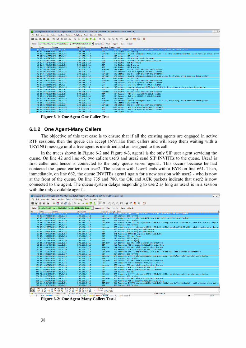
38
Figure 6-1: One Agent One Caller Test
6.1.2 One Agent-Many Callers The objective of this test case is to ensure that if all the existing agents are engaged in active
RTP sessions, then the queue can accept INVITEs from callers and will keep them waiting with a TRYING message until a free agent is identified and an assigned to this call.
In the traces shown in Figure 6-2 and Figure 6-3, agent1 is the only SIP user agent servicing the queue. On line 42 and line 45, two callers user3 and user2 send SIP INVITEs to the queue. User3 is first caller and hence is connected to the only queue server agent1. This occurs because he had contacted the queue earlier than user2. The session with User3 ends with a BYE on line 661. Then, immediately, on line 662, the queue INVITEs agent1 again for a new session with user2 - who is now at the front of the queue. On line 735 and 780, the OK and ACK packets indicate that user2 is now connected to the agent. The queue system delays responding to user2 as long as user3 is in a session with the only available agent1.
Figure 6-2: One Agent Many Callers Test-1
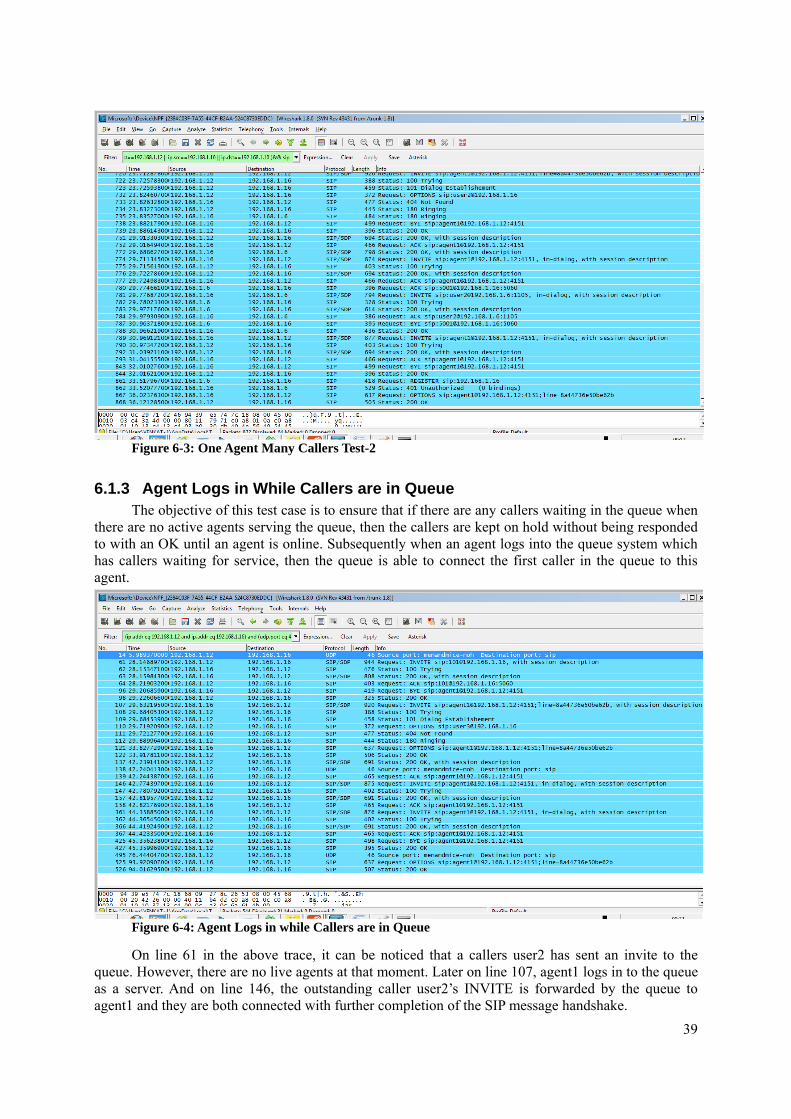
39
Figure 6-3: One Agent Many Callers Test-2
6.1.3 Agent Logs in While Callers are in Queue The objective of this test case is to ensure that if there are any callers waiting in the queue when
there are no active agents serving the queue, then the callers are kept on hold without being responded to with an OK until an agent is online. Subsequently when an agent logs into the queue system which has callers waiting for service, then the queue is able to connect the first caller in the queue to this agent.
Figure 6-4: Agent Logs in while Callers are in Queue
On line 61 in the above trace, it can be noticed that a callers user2 has sent an invite to the queue. However, there are no live agents at that moment. Later on line 107, agent1 logs in to the queue as a server. And on line 146, the outstanding caller user2’s INVITE is forwarded by the queue to agent1 and they are both connected with further completion of the SIP message handshake.
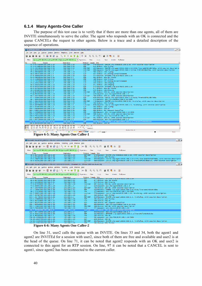
40
6.1.4 Many Agents-One Caller The purpose of this test case is to verify that if there are more than one agents, all of them are
INVITE simultaneously to serve the caller. The agent who responds with an OK is connected and the queue CANCELs the request to other agents. Below is a trace and a detailed description of the sequence of operations.
Figure 6-5: Many Agents One Caller-1
Figure 6-6: Many Agents One Caller-2
On line 31, user2 calls the queue with an INVITE. On lines 33 and 34, both the agent1 and agent2 are INVITEd for a session with user2, since both of them are free and available and user2 is at the head of the queue. On line 71, it can be noted that agent2 responds with an OK and user2 is connected to this agent for an RTP session. On line, 97 it can be noted that a CANCEL is sent to agent1, since agent2 has been connected to the current caller.
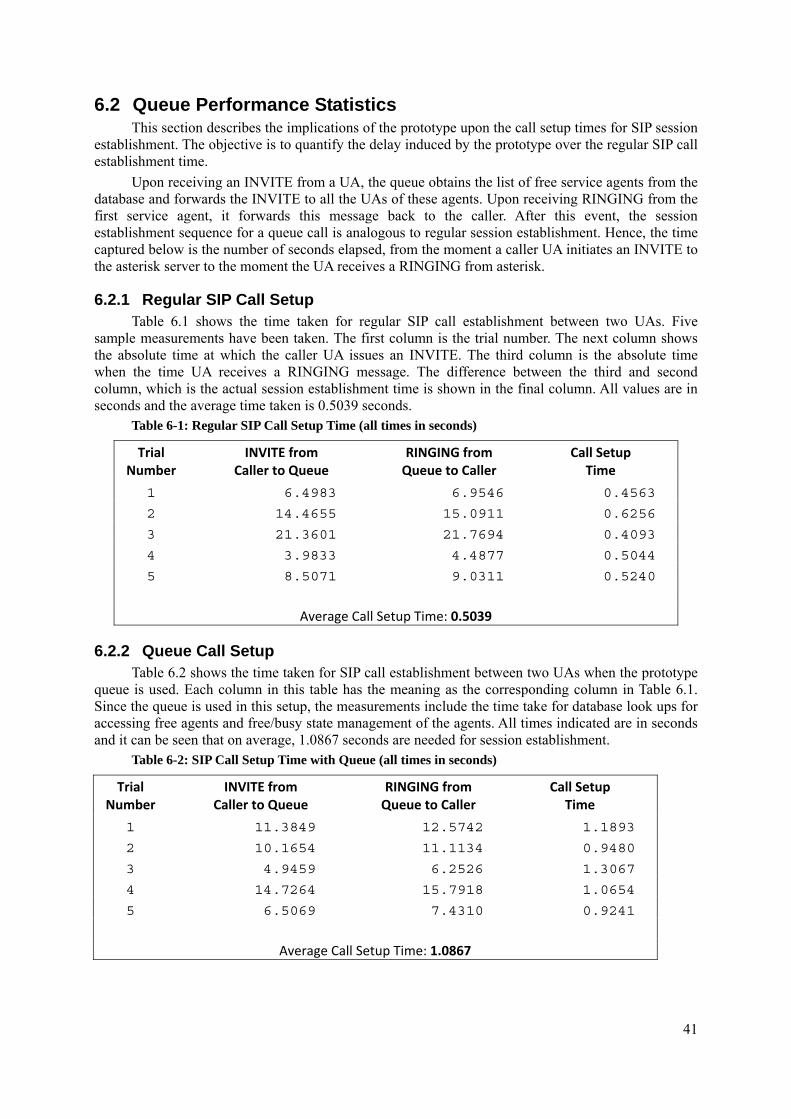
41
6.2 Queue Performance Statistics This section describes the implications of the prototype upon the call setup times for SIP session
establishment. The objective is to quantify the delay induced by the prototype over the regular SIP call establishment time.
Upon receiving an INVITE from a UA, the queue obtains the list of free service agents from the database and forwards the INVITE to all the UAs of these agents. Upon receiving RINGING from the first service agent, it forwards this message back to the caller. After this event, the session establishment sequence for a queue call is analogous to regular session establishment. Hence, the time captured below is the number of seconds elapsed, from the moment a caller UA initiates an INVITE to the asterisk server to the moment the UA receives a RINGING from asterisk.
6.2.1 Regular SIP Call Setup Table 6.1 shows the time taken for regular SIP call establishment between two UAs. Five
sample measurements have been taken. The first column is the trial number. The next column shows the absolute time at which the caller UA issues an INVITE. The third column is the absolute time when the time UA receives a RINGING message. The difference between the third and second column, which is the actual session establishment time is shown in the final column. All values are in seconds and the average time taken is 0.5039 seconds.
Table 6-1: Regular SIP Call Setup Time (all times in seconds)
Trial Number
INVITE from Caller to Queue
RINGING from Queue to Caller
Call Setup Time
1 6.4983 6.9546 0.4563
2 14.4655 15.0911 0.6256
3 21.3601 21.7694 0.4093
4 3.9833 4.4877 0.5044
5 8.5071 9.0311 0.5240
Average Call Setup Time: 0.5039
6.2.2 Queue Call Setup Table 6.2 shows the time taken for SIP call establishment between two UAs when the prototype
queue is used. Each column in this table has the meaning as the corresponding column in Table 6.1. Since the queue is used in this setup, the measurements include the time take for database look ups for accessing free agents and free/busy state management of the agents. All times indicated are in seconds and it can be seen that on average, 1.0867 seconds are needed for session establishment.
Table 6-2: SIP Call Setup Time with Queue (all times in seconds)
Trial Number
INVITE from Caller to Queue
RINGING from Queue to Caller
Call Setup Time
1 11.3849 12.5742 1.1893
2 10.1654 11.1134 0.9480
3 4.9459 6.2526 1.3067
4 14.7264 15.7918 1.0654
5 6.5069 7.4310 0.9241
Average Call Setup Time: 1.0867
42
6.2.3 Inferences The time statistics indicate that a significant delay is induced by using an external database to
maintain the state of all the SIP UAs in the queue. However, the functional test cases establish that this prototype architecture is a sufficient solution to implement a functional IVVR queue. It is also noteworthy that the database server and asterisk were running on the same machine. Externalizing the database to a separate machine on the network preserves computational resources for forwarding SIP signaling messages, but also gives rise to network access delay for accessing the database. This deployment topology should also be tested for derive complete statistics on this prototype.
43
7 Conclusion An IVVR system inherits all of the native issues of both two party video call establishment and
streaming static video files. The aim of this thesis project was to explore more precisely the root causes for these problems. The thesis project also aimed to construct a simple queuing system and use it as an interface for an IVVR system. While the first objective was met via a theoretical analysis and a simple queue was constructed, an IVVR with a transcoding video call could not be realized in the time period allocated for this thesis project.
However, the study of integrating asterisk with DiaStar provided in depth views of the technical hurdles specific to these two systems and some insights into the underlying SIP and NAT traversal issues. In particular, the measurements indicate that although a significant delay is introduced by the database, the prototype architecture is a sufficient for a practical IVVR queue system.
7.1 Future work The prototype lacks several features and extending this system to include these features will
enhance the system’s functionality. The following subsections describe some proposed future work.
7.1.1 NAT Traversal The complete system has been evaluated in the same local area network. Moving the IVVR
callers to a public network is an essential enhancement that would be needed before this system could be used in a real world deployment. As a first step the prototype IVVR should be extended to deal with NATs when the Asterisk server is facing the callers. The system components should be redesigned to include NAT traversal according to the relevant IETF RFCs.
7.1.2 Transcoding DiaStar is capable of streaming static video files to any client device by encoding the native file
format into the destination client’s prefered format. It is also capable of receiving RTP streams from multiple clients, mixing them in order to render the corresponding specific video format to every client. However, it is not possible to establish two party calls between clients having heterogeneous encoding schemes. A study to reuse the conferencing feature and tailor it to establish two party calls is possible.
As a second step one of the alternative Asterisk-DiaStar topologies could be considered and a working configuration implemented and evaluated.
7.1.3 Call back queue In this implementation, there is an active SIP session while the caller waits in the queue. It is
also possible to terminate this session when an active agent is not available, but retain the caller’s SIP identity and the queue position. These details can be used at a later point of time, when the respective caller is advanced to the first position in the queue to initiate a new SIP session. This alternate queue design allows caller’s client device to be free and the caller not manually wait for a connection.
7.2 Required reflections Widespread deployment of IVVRs can have some social and economic implications. This
section is a summary of such speculations. The greatest benefit is that the hearing impaired can use customized IVVR systems to avail themselves of support services from banks, electronic-device online support centers, and shopping centers. If the IVVR visuals are tailored to be independent of the spoken language, for instance, by representing all menu options in the form of pictures without using any text, IVVR systems can be reachable by geographically distant and wider audiences.
However, there are certain negative sides to widespread deployment of IVVRs also. Maintaining the video data generation and processing units requires more investment in hardware and software. So, only large organizations may be able to provide IVVR services. It may also be possible for back bone
44
network providers and cloud service organizations to supply the resources needed for IVVRs. On a social note, the employees working as agents in a support centre should be willing to participate in video communication with callers and the regional law should allow for video communication between strangers.
It is also notable that the degree to which these implications arise cannot be accurately determined before actually deploying and using IVVR systems.
45
Bibliography [1] Soonchul Jung, Moon-Suk Kang, Jae-Dong Lee, Dae-Woo Choi, and Jin Soo Sohn,
“Practical considerations to IVVR based ARS service creation,” presented at the 13th International Conference on Intelligence in Next Generation Networks, 2009 (ICIN 2009), Bordeaux, 2009, pp. 1–4.
[2] Dialogic Corporation, “IVVR Technology Introduction with Applications Using Dialogic® PowerMediaTM Host Media Processing Software,” Jul-2010. [Online]. Available: http://www.dialogic.com/~/media/products/docs/whitepapers/12026-ivvr-hmp-wp.pdf. [Accessed: 30-Jul-2012].
[3] G. Srinivasan, Lec-30 Queueing Models. Department of Management Studies, IIT Madras: , 2010.
[4] John D. C. Little and Stephen C. Graves, “Little’s Law (chapter 5),” in Building Intuition: Insights from Basic Operations Management Models and Principles, vol. 115, Dilip Chhajed and Timothy J. Lowe, Eds. New York, NY, USA: Springer Science+Business Media, Inc., 2008, pp. 81–100.
[5] Soonchul Jung, Moon-Suk Kang, Jae-Dong Lee, Dae-Woo Choi, Jin Soo Sohn, “Practical Considerations to IVVR based ARS.” [Online]. Available: http://ieeexplore.ieee.org/stamp/stamp.jsp?tp=&arnumber=5357088. [Accessed: 31-Jul-2012].
[6] ITU-T Recommendation Q.23, “ETSI Dual Tone Multi-Frequency (DTMF),” http://www.etsi.org/WebSite/Technologies/dtmf.aspx, 1963. [Online]. Available: http://www.etsi.org/WebSite/Technologies/dtmf.aspx. [Accessed: 03-Aug-2012].
[7] “IVVR Technology Introduction with Applications Using Dialogic® PowerMediaTM Host Media Processing Software.” .
[8] H. Schulzrinne, A. Rao, and R. Lanphier, “Real Time Streaming Protocol (RTSP),” Internet Request for Comments, vol. RFC 2326 (Proposed Standard), Apr. 1998.
[9] “ITU (International Telecommunication Union) is the United Nations specialized agency for information and communication technologies – ICTs.” .
[10] Eli Orr, “Understanding the 3G-324M Spec: Part 1,” EE Times, 21-Jan-2003. [Online]. Available: http://www.eetimes.com/electronics-news/4137042/Understanding-the-3G-324M-Spec-Part-1. [Accessed: 02-Sep-2012].
[11] International Telecommunication Union, “Recommendation ITU-T H.323.” Switzerland Geneva, 2010.
[12] M. Voznak, “Comparison of H. 323 and SIP Protocol Specification,” in International Conference" Research in Telecommunication Technology, 2003, pp. 45–47.
[13] “Cisco Voice Gateways and Gatekeepers.” . [14] J. Rosenberg, H. Schulzrinne, G. Camarillo, A. Johnston, J. Peterson, R. Sparks, M.
Handley, and E. Schooler, “SIP: Session Initiation Protocol,” Internet Request for Comments, vol. RFC 3261 (Proposed Standard), Jun. 2002.
[15] M. Handley, V. Jacobson, and C. Perkins, “SDP: Session Description Protocol,” Internet Request for Comments, vol. RFC 4566 (Proposed Standard), Jul. 2006.
[16] H. Schulzrinne, S. Casner, R. Frederick, and V. Jacobson, “RTP: A Transport Protocol for Real-Time Applications,” Internet Request for Comments, vol. RFC 3550 (Standard), Jul. 2003.
[17] C. Perkins and M. Westerlund, “Multiplexing RTP Data and Control Packets on a Single Port,” Internet Request for Comments, vol. RFC 5761 (Proposed Standard), Apr. 2010.
[18] C. Huitema, “Real Time Control Protocol (RTCP) attribute in Session Description Protocol (SDP),” Internet Request for Comments, vol. RFC 3605 (Proposed Standard), Oct. 2003.
46
[19] ITU-T Recommendation Q.23, “ETSI Dual Tone Multi-Frequency (DTMF),” http://www.etsi.org/WebSite/Technologies/dtmf.aspx, 1963. [Online]. Available: http://www.etsi.org/WebSite/Technologies/dtmf.aspx. [Accessed: 03-Aug-2012].
[20] “Q.23 : Technical features of push-button telephone sets.” [Online]. Available: http://www.itu.int/rec/T-REC-Q.23-198811-I. [Accessed: 03-Aug-2012].
[21] F. Audet and C. Jennings, “Network Address Translation (NAT) Behavioral Requirements for Unicast UDP,” Internet Request for Comments, vol. RFC 4787 (Best Current Practice), Jan. 2007.
[22] C. Boulton, J. Rosenberg, G. Camarillo, and F. Audet, “NAT Traversal Practices for Client-Server SIP,” Internet Request for Comments, vol. RFC 6314 (Informational), Jul. 2011.
[23] J. Rosenberg and H. Schulzrinne, “An Extension to the Session Initiation Protocol (SIP) for Symmetric Response Routing,” Internet Request for Comments, vol. RFC 3581 (Proposed Standard), Aug. 2003.
[24] J. Rosenberg, R. Mahy, P. Matthews, and D. Wing, “Session Traversal Utilities for NAT (STUN),” Internet Request for Comments, vol. RFC 5389 (Proposed Standard), Oct. 2008.
[25] R. Mahy, P. Matthews, and J. Rosenberg, “Traversal Using Relays around NAT (TURN): Relay Extensions to Session Traversal Utilities for NAT (STUN),” Internet Request for Comments, vol. RFC 5766 (Proposed Standard), Apr. 2010.
[26] “Asterisk- The Open Source Telephony Projects | Asterisk.” . [27] B. Foster and F. Andreasen, “Basic Media Gateway Control Protocol (MGCP)
Packages,” Internet Request for Comments, vol. RFC 3660 (Informational), Dec. 2003. [28] J. Loughney, G. Sidebottom, L. Coene, G. Verwimp, J. Keller, and B. Bidulock,
“Signalling Connection Control Part User Adaptation Layer (SUA),” Internet Request for Comments, vol. RFC 3868 (Proposed Standard), Oct. 2004.
[29] M. Spencer, B. Capouch, E. Guy, F. Miller, and K. Shumard, “IAX: Inter-Asterisk eXchange Version 2,” Internet Request for Comments, vol. RFC 5456 (Informational), Feb. 2010.
[30] M. Spencer, “Introduction to the Asterisk Open Source PBX,” Linux Support Services, Inc, 2002.
[31] Dialogic Corporation, “ProjectDiaStar.org.” [Online]. Available: http://www.projectdiastar.org/. [Accessed: 02-Sep-2012].
[32] CentOS Project, “www.centos.org - The Community ENTerprise Operating System.” [Online]. Available: https://www.centos.org/. [Accessed: 02-Sep-2012].
[33] wiki.projectdiastar.org, “Asterisk Client (chan woomera) - User’s Guide - ProjectDiaStar,” 16-Nov-2009. [Online]. Available: http://wiki.projectdiastar.org/index.php/Asterisk_Client_(chan_woomera)_-_User%27s_Guide. [Accessed: 02-Sep-2012].
[34] “Video Transcoding in DiaStar - ProjectDiaStar.” [Online]. Available: http://wiki.projectdiastar.org/index.php/Video_Transcoding_in_DiaStar#Streams_for_Play_and_Record. [Accessed: 08-Sep-2012].
[35] Linphone, “Linphone, open-source voip software,” 16-Feb-2012. [Online]. Available: http://www.linphone.org/. [Accessed: 02-Sep-2012].
[36] “Fedora Project Homepage.” [Online]. Available: http://fedoraproject.org/. [Accessed: 08-Sep-2012].
[37] “Free VMware Player: Run Windows 8, Chrome OS on a Virtual PC.” [Online]. Available: http://www.vmware.com/products/player/. [Accessed: 08-Sep-2012].
[38] “phpMyAdmin.” [Online]. Available: http://www.phpmyadmin.net/home_page/index.php. [Accessed: 08-Sep-2012].
[39] “Wireshark · Go deep.” [Online]. Available: http://www.wireshark.org/. [Accessed: 08-Sep-2012].
[40] “Perl DBI - dbi.perl.org.” [Online]. Available: http://dbi.perl.org/. [Accessed: 08-Sep-2012].
47
[41] “VirtualBox Downloads.” [Online]. Available: http://www.oracle.com/technetwork/server-storage/virtualbox/downloads/index.html. [Accessed: 08-Sep-2012].
[42] “Diagram Designer.” [Online]. Available: http://logicnet.dk/DiagramDesigner/. [Accessed: 08-Sep-2012].
[43] “Asterisk to DiaStar SIP Scenarios - ProjectDiaStar.” [Online]. Available: http://wiki.projectdiastar.org/index.php/Asterisk_to_DiaStar_SIP_Scenarios. [Accessed: 08-Sep-2012].

www.kth.se
TRITA-ICT-EX-2012:201