Embed Size (px)
Citation preview
Rochester Institute of TechnologyRIT Scholar Works
Theses Thesis/Dissertation Collections
10-1-1982
Analysis of Ink Film Thickness on ScreenlessLithographic Plates by MicroscopyJames Spruill Summers
Follow this and additional works at: http://scholarworks.rit.edu/theses
This Thesis is brought to you for free and open access by the Thesis/Dissertation Collections at RIT Scholar Works. It has been accepted for inclusionin Theses by an authorized administrator of RIT Scholar Works. For more information, please contact [email protected].
Recommended CitationSummers, James Spruill, "Analysis of Ink Film Thickness on Screenless Lithographic Plates by Microscopy" (1982). Thesis. RochesterInstitute of Technology. Accessed from
ANALYSIS OP INK FILM THICKNESS
ON SCREENLESS LITHOGRAPHIC PLATES
BY MICROSCOPY
by
James Spruill Summers
A thesis submitted in partial fulfillment of the
requirements for the degree of Master of Science in the
School of Printing in the College of Graphic Arts and
Photography of the Rochester Institute of Technology
October, 1982
Thesis Advisor: Professor Julius Silver
School of Printing Rochester Institute of Technology
Rochester, New York
CERTIFICATE OF APPROVAL
MASTER'S THESIS
This is to certify that the Master's Thesis of
James S. Summers
with a major in Printing Technology has been approved by the Thesis Committee as satisfactory for the thesis requirement for the Master of Science degree at the convocation of
October 1982
Thesis Committee: Julius Silver ~T~h~e~s~i~s~Ard~v-l~'s-o-r----------------
Mark F. Guldin Director or Designate
Copyright 19 82 James S. Summers
No part of this thesis may be reproduced
in whole or in part without written
permission from the author.
ACKNOWLEDGEMENTS
Many people contributed to the success of this thesis
whose names are too numerous to mention. I wish to express
my gratitude to the following people who were especially
helpful. Mr. Raymond Badum, Dr. Chris Nilsen, and Dr.
Robert Snyder for their advice and assistance in metalurgy
and sample preparation. Dr. Thomas Frederick for instruction
in the use of the SEM. Mr. Lloyd Swisher for his contribu
tions in time and materials in ink technology. Mr. Leslie
Lawson, Mr. William Springfield, and Mr. Patrick Hanlon for
their generous contributions of time and materials which made
use of Alympic Gold plates possible. Dr. Julius Silver for
his patience, advice, and constructive criticism. Dr. Frank
W. Summers, my father, for his continuous support, sugges
tions, and understanding through the years.
11
TABLE OF CONTENTS
LIST OF TABLES v
LIST OF FIGURES vi
ABSTRACT 1
Chapter
I. INTRODUCTION 1
II. THEORY OF SCREENLESS LITHOGRAPHY 3
Hypothesis 5
Footnotes for Chapter II 6
III. LITERATURE REVIEW 7
Methods of Unscreened Printing 8
Collotype 8
Gravure 9
Screenless Lithography 9
Advantages and Disadvantages of
Screenless Lithography 11
Footnotes for Chapter III 14
IV. METHODOLOGY 16
Introduction 16
General Methodology 17
Plate Preparation 17
Scanning Electron Microscopy 19
Fluorescent Microscopy
m
TABLE OF CONTENTS (Continued)
Footnote for Chapter IV 25
V. DATA ANALYSIS 26
VI. DISCUSSION OF RESULTS 30
Footnotes for Chapter VI 43
VII. SUMMARY AND CONCLUSION 44
VIII. RECOMMENDATIONS FOR FURTHER RESEARCH 45
GENERAL REFERENCE 46
APPENDIX A 48
APPENDIX B 49
IV
LIST OF TABLES
TABLE 1 Fuji Plate 1 27
TABLE 2 Fuji Plate 2 27
TABLE 3 Kodak Plate 1 27
TABLE 4 Kodak Plate 2 27
TABLE 5 Enco Plate 1 27
TABLE 6 Enco Plate 2 27
TABLE 7 Howson-Algraphy Plate 1 28
TABLE 8 Howson-Algraphy Plate 2 28
TABLE 9 Howson-Algraphy Plate 3 28
TABLE 10 Howson-Algraphy Plate 4 28
TABLE 11 Howson-Algraphy Plate 5 28
TABLE 12 Howson-Algraphy Plate 6 28
TABLE 13 Howson-Algraphy Plate 7 29
TABLE 14 Howson-Algraphy Plate 8 29
TABLE 15 Ink Tack Readings 47
v
LIST OF FIGURES
FIGURE 1 Processed Plate Model 4
FIGURE 2 Actual Plate Topography Model 4
FIGURE 3 Ink Film Thickness vs. Relative LogExposure for Fuji Plate 1 32
FIGURE 4 Ink Film Thickness vs. Relative LogExposure for Fuji Plate 2 32
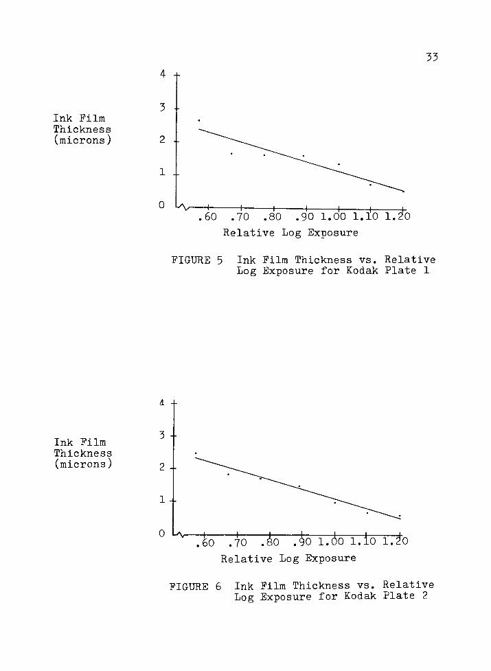
FIGURE 5 Ink Film Thickness vs. Relative LogExposure for Kodak Plate 1 33
FIGURE 6 Ink Film Thickness vs. Relative LogExposure for Kodak Plate 2 33
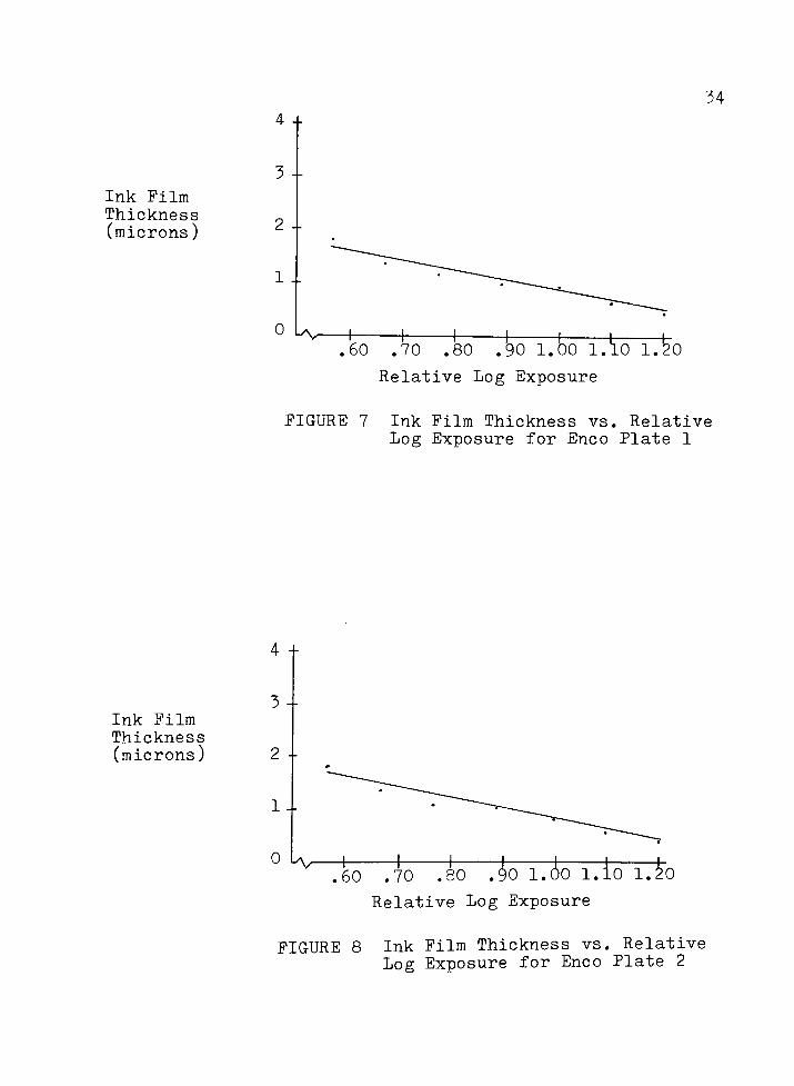
FIGURE 7 Ink Film Thickness vs. Relative LogExposure for Enco Plate 1 34
FIGURE 8 Ink Film Thickness vs. Relative LogExposure for Enco Plate 2 34
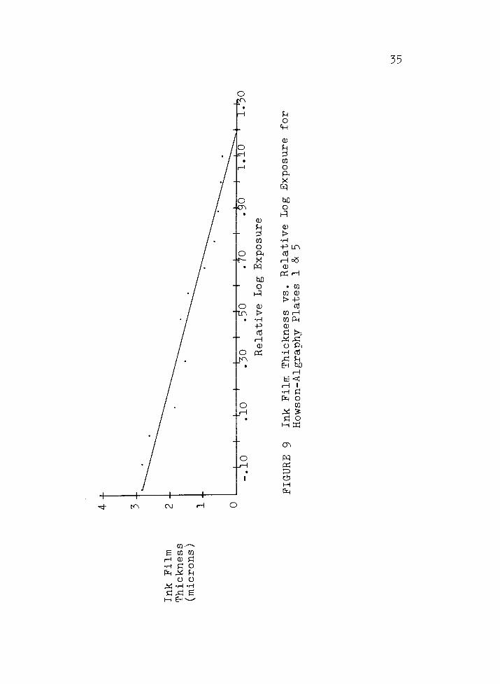
FIGURE 9 Ink Film Thickness vs. Relative LogExposure for Howson-AlgraphyPlates 1&5 35
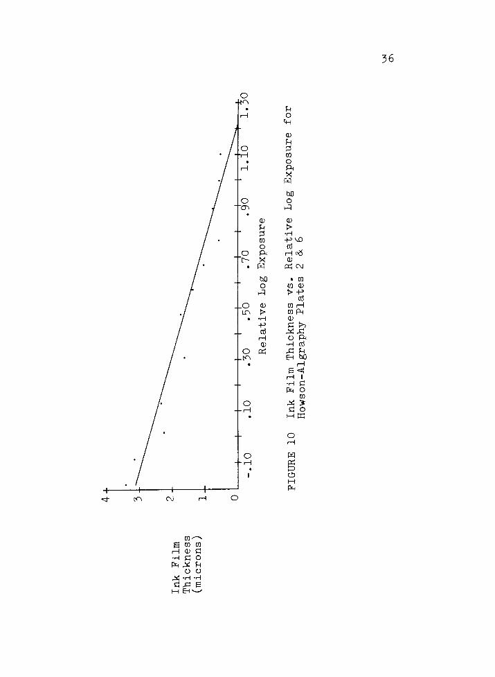
FIGURE 10 Ink Film Thickness vs. Relative LogExposure for Howson-AlgraphyPlates 2 & 6
"
36
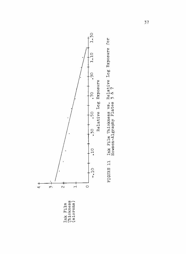
FIGURE 11 Ink Film Thickness vs. Relative LogExposure for Howson-AlgraphyPlates 3 & 7 37
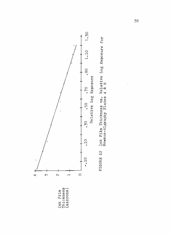
FIGURE 12 Ink Film Thickness vs. Relative LogExposure for Howson-AlgraphyPlates 4 & 8 38
FIGURE 13 Photomicrograph 1 39
vi
LIST OF FIGURES (continued)
FIGURE 14 Photomicrograph 2 39
FIGURE 15 Photomicrograph 3 40
FIGURE 16 Photomicrograph 4 40
FIGURE 17 Solubility Plate Model 41
VII
ABSTRACT
Printing without the use of a halftone screen pattern
offers many advantages, although most processes utilized are
impractical for long run commercial printing. Screenless
lithography provides a practical means of making unscreened
reproductions .
While screenless lithography has been in use for many
years, its working mechanisms have only recently been
explained. Past studies have investigated many of the
factors which contribute to the continuous tone effect of
screenless printing, but none have scientifically determined
if ink film thickness variation is a contributing factor.
Positive working lithographic plates were exposed to
control scales, processed, inked, and allowed to dry. These
plates were then cross-sectioned and observed under a high
magnification microscope to determine if variations in ink
film thickness exist.
Results showed that variations did indeed exist. These
variations were shown to occur not only between areas of
different density, but also within areas of uniform density.
The different ink film thicknesses that exist on screen
less lithographic plates affect their tone reproduction
characteristics and contribute to their continuous tone
capabilities.
CHAPTER I
INTRODUCTION
Since its inception, screenless lithography has come to
be known by a wide variety of names: grainless lithography,
random dot printing, unscreened printing, continuous tone
lithography, random grain printing, and even controlled scum.
The most widely used designation is screenless lithography
and this term, or simply screenless, will be used throughout
this paper.
Screenless lithography will be defined as the process of
using positive working lithographic plates, without a screen
pattern, for reproducing continuous tone originals.
Whether or not screenless is a continuous tone process
has been a source of confusion for some time. This, of
course, depends on how one defines continuous tone. Technic
ally speaking, no continuous tone method of recording or
reproducing reality exists. All systems involve some dis
crete point for recording information, a silver halide crys
tal for example. For practical purposes, continuous tone is
recorded information which the naked eye cannot resolve into
discrete points. Continuous tone printing will be defined in
this paper as the ability to print an ink film which varies
in thickness between areas of different density and has a
randomly distributed grain pattern. The purpose of this
study is to determine if ink film thickness varies on
screenless lithographic plates.
The project involves: production of screenless plates
with test areas suitable for producing the necessary data,
preparation of those plates for viewing with a high magnifi
cation microscope, analysis and generation of data with the
microscope, and evaluation of data thus obtained.
Ink on paper printing methods which closely approximate
the photographically printed image are generally not practi
cal in a commercial environment. This is due to their vari
ability, or the skill required to work with the process.
Economics demand that any printing process, to be commercial
ly viable, must be relatively easy to use and capable of
producing long runs. The areas which are difficult to define
are high quality, easy to use, long run, and commercially
viable. A market will always exist for the very best
printing available. Screenless lithography is a process
somewhere between tedious, finicky collotype and the coarse,
lower quality halftone processes. A better understanding of
screenless lithography may help to continue its use as an
economical, quality printing process.
CHAPTER II
THEORY OF SCREENLESS LITHOGRAPHY
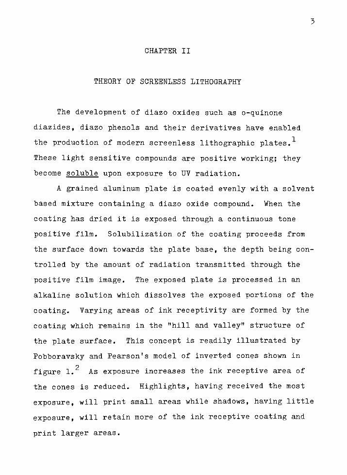
The development of diazo oxides such as o-quinone
diazides, diazo phenols and their derivatives have enabled
the production of modern screenless lithographic plates.
These light sensitive compounds are positive working; they
become soluble upon exposure to UV radiation.
A grained aluminum plate is coated evenly with a solvent
based mixture containing a diazo oxide compound. When the
coating has dried it is exposed through a continuous tone
positive film. Solubilization of the coating proceeds from
the surface down towards the plate base, the depth being con
trolled by the amount of radiation transmitted through the
positive film image. The exposed plate is processed in an
alkaline solution which dissolves the exposed portions of the
coating. Varying areas of ink receptivity are formed by the
coating which remains in the "hill andvalley"
structure of
the plate surface. This concept is readily illustrated by
Pobboravsky and Pearson's model of inverted cones shown in
figure 1. As exposure increases the ink receptive area of
the cones is reduced. Highlights, having received the most
exposure, will print small areaswhile shadows, having little
exposure, will retain more of the ink receptive coating and
print larger areas.
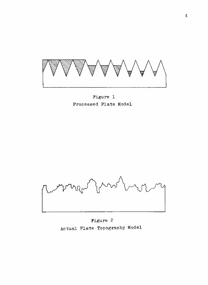
Figure 1
Processed Plate Model
Figure 2
Actual Plate Topography Model
The inverted cone model is only a representation of the
image forming mechanism in screenless lithography. Actual
plate topography is a randomly grained surface as shown in
3figure 2.
Many studies have explored the variables which influence
tone reproduction characteristics of screenless plates, but
few have postulated the exact working mechanisms of such
plates. Pobboravsky and Pearson state: "Although screenless
lithography is called a continuous tone process, the printed
image is not a continuous film of ink, but is made up of ran
domly distributed spots of ink that vary in size and are
irregularlyshaped."
They worked under the premise that
"the lightness of a given tone seems to be due to the average
area of a large number of ink spots that cover thepaper."
Other sources indicate that ink film thicknesses vary within
the plate.
The fact that the grained plate surface both produces
and markedly influences the ability to achieve the screenless
effect is not challenged. The objective is to analyze
screenless lithographic plates to determine if there actually
is variability in ink film thicknesses.
HYPOTHESIS
Variations exist in the ink film thickness of positive
workinglithographic plates.
FOOTNOTES FOR CHAPTER II
Jaromir Kosar, Light Sensitive Systems: Chemistry and
Application of Non-Silver Halide Photographic Processes,
(New York: John Wiley & Sons, Inc., 1965,, pp. 50-51.
Irving Pobboravsky and Milton Pearson, "Study of
ScreenlessLithography,"
TAGA Proceedings 1967, pp. 259, 260.
3Ibid., p. 256.
4Ibid., p. 251.
5Ibid.
"ScreenlessLithography," Graphic Arts Japan 16 (1975-
1976): 50.
CHAPTER III
LITERATURE REVIEW
The first unscreened prints were also the first photo
mechanical reproductions. In 1827 Joseph Nicephone Niepce
used bitumen sensitized plates to reproduce an engraving.
Others following him obtained the first screenless litho
graphic prints by coating bitumen on grained lithographic
2stones. L.P. Clerc fully described the function of the
stones'
grain in achieving printing areas which correspond to
the degree of exposure received. In 1855 Alphonse Poitevin
patented a method for photolithography using albumen and
5potassium dichromate coated on lithographic stones.
Processes such as these were still in use as late as 1924.
During World War II the Germans discovered diazo oxide
compounds which opened the way for development of modern,
5positive working lithographic plates.
In 1951 the first presensitized, brush grained, positive
working lithographic plate made its appearance on the U.S.
market. This plate, an ENCO product, was not intended for
screenless use. Nevertheless, experimental screenless
lithography with this product as well as negative working
plates shortly followed.
Sumner Williams introduced a wipe-on positive working
plate in 1961 with excellent resolution that was used for
8
reproducing aerial photographs.
A patent was issued to M.M. Ruderman in 1966 titled
"Planographic Printing Plate andProcess" (U.S. Patent
3,282,208). Mr. Ruderman described the process as "a pure
chemical and mechanical condition. It is a diazo printing
process where each molecule of diazo will attract the same
7size molecule of
ink."
Pobboravsky and Pearson, in 1967, determined that plate
grain was necessary to produce the continuous tone effect in
o
screenless lithography.
While screenless lithography has existed since the
1800 's a complete explanation of how the continuous tone
effect is produced remains to be made.
Methods of Unscreened Printing
Collotype
A dichromated colloid coated on a glass or metal base
forms the plate for the collotype process. Exposure and
development produces a reticulated grain pattern which varies
in hardness proportionally to the amount of exposure received.
Ink receptivity of the plate differs with the hardness of the
colloid, thus the collotype plate is able to produce a full
range of tones without using a screen pattern. While collo
type does produce outstanding results, the consistency of
color during a press run and limit of about 2,000 impressions
per plate have confined its use to short run, specialized
applications.
Gravure
Although current production of gravure cylinders and
plates uses a screened image or grid pattern, older varia
tions of the gravure process, such as aquatint, did not
incorporate this procedure. A random grained image was
created by dusting resin onto the prepared copper plate
prior to the application of a dichromated gelatin resist.
Washing of the gelatin and subsequent etching of the plate in
a ferric chloride bath produced an intaglio plate which
varied in depth from highlights to shadows. The printed
reproduction was an image with a variable ink film thickness
and a random grain pattern.
Screenless Lithography
The screenless lithographic process is nothing new. It
was used extensively prior to the invention of the halftone
-| pscreen. Early workers in this process used lithographic
stones with a light sensitive coating of bitumen (asphalt).
The coating filled holes in the stone's porous surface. A
continuous tone negative provided varying degrees of exposure
to the coating which became insolubilized. Unexposed por
tions of the coating were removed during development. A
layer of bitumen remained, the area of which corresponded to
13the degree of exposure received from the negative.
10
Modern day users of screenless lithography employ
grained aluminum plates coated with a positive or negative
working light sensitive layer.
The effect produced by a negative working coating is an
image structure which resides on the peaks of the plate grain.
Such an image is unprotected and rapidly deteriorates on the
press, thus all contemporary users of screenless lithography
utilize positive working, diazo oxide coatings. It is this
group of light sensitive materials which make screenless
printing commercially feasible.
With positive working materials the image formed rests
below the grain peaks of the plate's surface. The peaks act
as a protective layer for the positive working material and
15permit runs up to 50,000 impressions.
As with the early stone and bitumen process, modern
positive working screenless lithographic plates rely on the
grain, and thickness of the light sensitive coating, to
create their tone reproduction characteristics. Pobboravsky
and Pearson's research has shown that plate grain is respon
sible for producing varying areas of ink receptivity.
Further research proved coarse graining produces the greatest
density range.
Manipulations of plate exposure such as post exposure
flashing, without the positive film, have been shown to lower
the plate's Variations in processing conditions
11
have also been used to lower the contrast range of the plate,
resulting in better separation of tonal values in the printed
image, and a closer approximation of the original.
Advantages and Disadvantages of Screenless Lithography
Screenless lithography offers a number of advantages
over conventional screened lithography:
-High Resolution - The resolution of a screenless image
is limited only by the grain size of the plate. Details are
not obscured by the introduction of a screen pattern which
19can be larger than the detail to be reproduced.
-Elimination of Moire Pattern - Irregular graining in
the plate eliminates the possibility of moire patterns.
These could be induced by more than one halftone screen or
interactions between a screen pattern and a pattern in the
. . , . 20original image.
-Smooth Tonal Gradation - There are no sharp density
changes which occur in halftone patterns when 50% dots begin
21connecting.
-Saturation of Pastel Colors - Pastels and delicate
shades of color are reproduced with greater saturation than
22with halftones.
In addition to these advantages the entire process of
making and correcting a halftone is eliminated, resulting in
significant time and cost reductions.
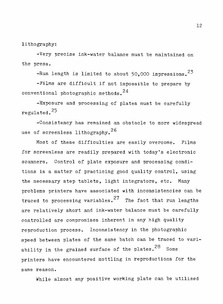
Some disadvantages are also associated with screenless
12
lithography:
-Very precise ink-water balance must be maintained on
the press.
-Run length is limited to about 50,000 impressions.2^
-Films are difficult if not impossible to prepare by
conventional photographic methods.^
-Exposure and processing of plates must be carefully
25regulated.
-Consistency has remained an obstacle to more widespread
0 l/H
use of screenless lithography.
Most of these difficulties are easily overcome. Films
for screenless are readily prepared with today's electronic
scanners. Control of plate exposure and processing condi
tions is a matter of practicing good quality control, using
the necessary step tablets, light integrators, etc. Many
problems printers have associated with inconsistencies can be
27traced to processing variables. The fact that run lengths
are relatively short and ink-water balance must be carefully
controlled are compromises inherent in any high quality
reproduction process. Inconsistency in the photographic
speed between plates of the same batch can be traced to vari-
po
ability in the grained surface of the plates. Some
printers have encountered mottling in reproductions for the
same reason.
While almost any positive working plate can be utilized
13
for screenless printing, only a few are acceptable. Plate
manufacturers generally do not intend their positive working
plates to be used for screenless work, hence they are not
specifically grained for that purpose. For normal halftone
and linework, the grain serves to improve adhesion of the
light sensitive coating, to aid retention of fountain solu
tion during printing, prevent skidding or burnishing, and to
pqaid formation of a vacuum between the film and plate. In
screenless the grain functions for more than mechanical
purposes; it forms the image areas.
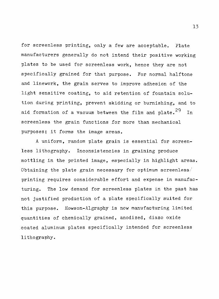
A uniform, random plate grain is essential for screen
less lithography. Inconsistencies in graining produce
mottling in the printed image, especially in highlight areas.
Obtaining the plate grain necessary for optimum screenless /
printing requires considerable effort and expense in manufac
turing. The low demand for screenless plates in the past has
not justified production of a plate specifically suited for
this purpose. Howson-Algraphy is now manufacturing limited
quantities of chemically grained, anodized, diazo oxide
coated aluminum plates specifically intended for screenless
lithography.
14
FOOTNOTES FOR CHAPTER III
1
William Crawford, The Keepers of Light. (New York:
Morgan & Morgan, 1979), pp. 246T 247.
2Irving Pobboravsky and Milton Pearson, "Study of
Screenless Lithography,"TAGA Proceedings 1967. p. 260.
3Crawford, Keepers, p. 269.
4L.E. Lawson, TAGA Proceedings 1978. p. 46.
5"Continuous tone litho comes to
Australia,"The
Australasian Printer, April 1967, p. 23.
F. Uhlig, "Screenless Offset Printing Process UsingPresensitized Printing
Plates,"The Journal of Photographic
Science 18 (January-February 1970): 5.
7"Now, It's Screenless
Lithography,"
Printing
Production, December 1968, p. 39.
8Pobboravsky and Pearson, TAGA, pp. 259-260.
Jaromir Kosar, Light Sensitive Systems: Chemistry and
Application of Non-Silver Halide Photographic Processes,(New York: John Wiley & Sons, Inc., 1965), pp. 50-51.
10Ibid.
i:LCrawford, Keepers, pp. 246, 247.
1 pRobert J. Lefebvre, Printing in the 20th Century: A
Penrose Anthology, (New York: Hastings House, 1974), p. 295.
*L.P. Clerc, Ilford Manual of Process Work, (London:
1923), p. 158.
^Lawson, TAGA, p. 46.
15Ibid.
l6Pobboravsky and Pearson, TAGA, pp. 259-260.
15
7Dr. Len Watkinson, "The Effect of Plate Surface on
PrintingQualities," The Australasian Printer, June 1978,
p. 16.
1 8Tomoaki Ikeda, Kiroji Kumagai, and Kiyoshi Masui,
"Tone Reproduction in Screenless Lithography," Graphic Arts
Japan 10 (1968-1969): 43, 44.
19"Continuoustoneprinting: Gimmick or
Breakthrough?,"
Book Production Industry, June 1967, p. 45.
20Pobboravsky and Pearson, TAGA, p. 250.
21"Continuoustoneprinting,"p. 45.
22Ibid.px
^Lawson, TAGA, p. 46.
OA
I. Gregg VanWert, "An Approach to Continuous Tone
Lithography for Web & Sheetfed,"Printing Magazine. May 1973,
pp. 24-25.
25Lawson, TAGA, pp. 50-51.
26Watkinson, "TheEffect,"
p. 15.
27VanWert, "AnApproach,"
pp. 24-25.
"ScreenlessLithography,"
Graphic Arts Japan 16
(1975-1976): 50.
29Watkinson, "TheEffect,"
p. 13.
16
CHAPTER IV
METHODOLOGY
Introduction
Classical means for measuring ink film thickness, such
as a densitometer, were inadequate for this study. A reflec
tion densitometer integrates substrate influences, scattering
of light within the ink film, printed area, and a number of
other factors which do not necessarily relate to changes in
ink film thickness. Furthermore, a densitometer does not
measure physical ink film thickness. It can measure changes
in reflection density caused by changes in actual ink film
thickness, but these changes are not numerically proportional
to changes in ink film thickness. It is a common misconcep
tion that densitometers can measure ink film thickness.
Ink films were measured directly from plates. This
splitting could also induce more variability. The splitting
of an ink film between the plate and blanket of an offset
press and subsequent splitting again between blanket and
paper greatly reduce the film's thickness, making it more
difficult to measure. For these reasons, as well as accuracy,
measurement directly from the plate was chosen.
17
General Methodology
Four different brands of positive working lithographic
plates were used: Enco P-30, Kodak P, Fuji FPD, and Howson-
Algraphy Alympic Gold. All plates were exposed and processed
by hand according to the manufacturer's recommendations.
Kodak T-14 and T-21 step control scales were used for test
targets. Their progressively stepped density ranges of 1.63
and 1.77, respectively, exceeds those found in continuous
tone separations normally used for screenless work. The con
trol scales provided the contrast necessary for differentia
ting between adjoining steps on low contrast plates.
An offset lithographic duplicator was used for running
tests prior to inking full size plates on a standard offset
lithographic press. The press provided more precise control
and uniform inking. Initially, plates were inked with
standard sheetfed inks and conventional fountain solutions.
Plates were removed from the press and the ink was allowed to
completely dry prior to preparation for the microscope.
Plate Preparation
A wide variety of methods were used for preparing the
plates for the microscopes. Metalurgical studies of thin
gauge plates are commonly done by first casting the sample in
18
resin. A cast serves as a holding device during the subse
quent polishing operations and helps eliminate deformation
induced during the abrasive polishing of soft metals. Next,
the cast is subjected to progressively finer grits of emery
paper. This is followed by another progression of polishings
with aqueous suspensions of silica particles on rotating,
cloth covered wheels. Final polishing particle size is .06
microns, considerably smaller than the 1.0 micron average ink
pigment particles being observed. This extremely fine
polishing is necessary to eliminate distortion and deforma
tion in the cross sectioned plate surface caused by cutting
the plate.
Unfortunately, soft metals, like the aluminum alloys
used in lithographic plates, are very difficult to polish.
Aluminum fills the surface of abrasive polishers and
transfers back to the sample being polished, resulting in
smearing of the surface. Differences in rate of material
removal between the cast material and the sample being
polished produced distortion at the cast-sample interface.
Further problems were caused by the soft, flexible nature of
the photopolymer and ink layers. Experimentation with the
polishing technique finally minimized distortion and provided
an acceptable sample.
Another method common to sample preparation for metal
lurgical studies utilizes a silicon carbide abrasive cut-off
19
wheel with a continuous flow of cutting fluid. The sample is
cast in the same resin as before and cross-sectioned using
the wheel. Subsequent polishing is not used. This method
yielded samples with 80 percent of their area undistorted and
suitable for viewing with a microscope. Because sample
preparation time was substantially reduced, this method was
used for preparing all the following samples.
Scanning Electron Microscopy
Initially the scanning electron microscope (SEM) was
selected for measuring ink film thickness because of its
ability to resolve extremely fine detail. An optical micro
scope has a limit of about 2000x before image quality becomes
unsatisfactory. The SEM provided far greater magnifications,
making accurate measurement of ink film thickness in the
micron range a much easier task.
Difficulties, however, were encountered when using the
SEM. A phenomenon referred to as"charging,"
caused by the
dielectric property of the epoxy material, degraded resolu
tion to an unacceptable level. Rather than attempt the use
of conductive epoxies, a better method of sample preparation
was sought which would eliminate any intervention by the
holding material during SEM examination.
A metal holding clamp was custom fabricated by the
20
author under the direction of Dr. Chris Nilsen (College of
Engineering, R.I.T.). It provided a means for holding the
plate sample during polishing operations and was easily
removed prior to SEM observation. This device produced dis
tortion at the sample-clamp interface due to different rates
of material removal between the aluminum plate and steel
clamp. Efforts were directed back towards a conductive epoxy.
Impregnation of the resin material with finely powdered
conductive metals greatly reduced charging. Careful mounting
of the samples on the stubs used in the SEM with conductive
tape and carbon paint also served to reduce charging and
provide acceptable image quality.
Once this was accomplished, another problem was encoun
tered. Insufficient contrast between the plate's photopoly
mer coating and the ink film did not allow accurate judgment
of the ink film thickness. This was due to the similarities
in electrical conductivity between the two materials and the
fact that a standard SEM relies on differences in topography
and conductivity to produce an image. Topography differences
were eliminated in the previously mentioned polishing opera
tion. Without different conductivity between the ink and
photopolymer layers, image contrast was nonexistent.
Tests with various conventional inks revealed no
substantial differences in conductivity because all contain
essentially the same pigment to vehicle ratio, the vehicle
21
being nonconductive. What was needed was a conductive ink.
Such inks are not available for lithography. While these
inks are common in the circuit printing industry, their
rheological properties are not suitable for use in
lithography.
Different types of inks were used in an effort to pro
vide the necessary contrast. Aluminum based metallic inks
and ferric oxide based magnetic inks specifically formulated
for lithography were used to ink the plates. Samples were
prepared and observed under the SEM. While contrast between
the layers was present, it was judged insufficient for
accurate interpretation of ink film thickness variability.
An electron-probe microanalyzer probably would allow
accurate analysis of plate samples. Such a unit scans the
sample surface and supplies information on the elements
existing in the sample. Photopolymers , inks, and aluminum
are markedly different in elemental composition and would
exhibit excellent contrast between layers. Electron-probe
microanalysis was not readily available for use in this
thesis and no experimental validity of this theory is
provided.
At this point the SEM, without electron-probe micro
analysis, was judged incapable of providing the contrast
necessary to accept or reject the hypothesis. A completely
new approach was needed.
22
Fluorescent Microscopy
Initial experimentation with a conventional light micro
scope showed that contrast was also a problem with this
instrument, even with inks complementary in color to the
photopolymer coating. Use of an oil immersion lens providing
higher magnification improved contrast, but not to a satis
factory level. Many types of optical microscopy exist and
research suggested ultraviolet (UV) microscopy might be
suitable.
Three distinct advantages of the UV microscope over the
SEM are elimination of charging problems, ease of sample
mounting, and reduced time necessary for analyzing each
sample. With the SEM one must wait for vacuum chamber draw
down, instrument adjustment for optimum picture quality, and
for the chamber to return to ambient pressure after viewing
the sample. This must be done for each sample and consider
able time is consumed in viewing each sample, if it proves to
be unsuitable.
Maximum interlayer contrast is obtained with the UV
microscope by using an ink which fluoresces. While many
fluorescent inks suitable for conventional lithography are
available, inks suitable for screenless applications are
those which perform well with extremely fine (300 line)
halftone work.
23
Test plates were inked on a duplicator with an ink which
fluoresced blue, allowed to dry, and then prepared for the UV
microscope. Again, insufficient contrast between layers was
encountered. The blue fluorescence of the ink was very simi
lar in color to the visible portion of the UV radiation
reflected by the sample. Thus, the color contrast was inade
quate for reliable interpretation of ink film thickness varia
bility. Filtering out all visible light from the UV radiation
source reduced its intensity to a level where fluorescence of
the ink layer was no longer visible.
Although many inks are available which fluoresce in
colors complementary to the blue-purple end of the visible
spectrum, such as the Dayglo brand inks, press runs proved
such inks unsuitable for screenless lithography. Plates
which had five different control scale steps prior to inking
would provide only one or two differently inked steps.
Considerable manipulation of the ink-water balance proved
these inks would simply not function properly with screenless
lithographic plates. Even so, a plate prepared for the
microscope showed the fluorescent properties of this type of
ink would provide the contrast necessary for evaluation of
ink film thickness.
Some types of conventional process yellow lithographic
inks will fluoresce. Studies showed that their intensity of
fluorescence was far below that of inks specifically
24
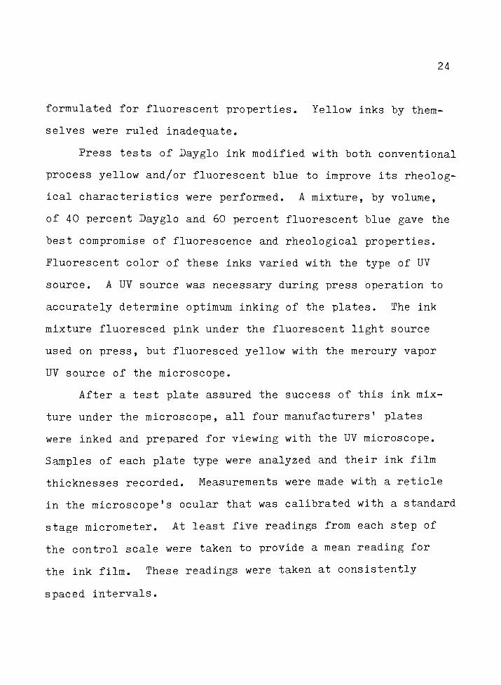
formulated for fluorescent properties. Yellow inks by them
selves were ruled inadequate.
Press tests of Dayglo ink modified with both conventional
process yellow and/or fluorescent blue to improve its rheolog
ical characteristics were performed. A mixture, by volume,
of 40 percent Dayglo and 60 percent fluorescent blue gave the
best compromise of fluorescence and rheological properties.
Fluorescent color of these inks varied with the type of UV
source. A UV source was necessary during press operation to
accurately determine optimum inking of the plates. The ink
mixture fluoresced pink under the fluorescent light source
used on press, but fluoresced yellow with the mercury vapor
UV source of the microscope.
After a test plate assured the success of this ink mix
ture under the microscope, all fourmanufacturers'
plates
were inked and prepared for viewing with the UV microscope.
Samples of each plate type were analyzed and their ink film
thicknesses recorded. Measurements were made with a reticle
in the microscope's ocular that was calibrated with a standard
stage micrometer. At least five readings from each step of
the control scale were taken to provide a mean reading for
the ink film. These readings were taken at consistently
spaced intervals.
25
FOOTNOTE FOR CHAPTER IV
J.A.C. Yule, Principles of Color Reproduction, (NewYork: John Wiley & Son, Inc., 1967), pp. 205-216.
26
CHAPTER V
DATA ANALYSIS
It soon became apparent that ink film thicknesses did
vary consistently from high to low exposure in all four
brands of plates. The Howson-Algraphy plates produced an
extremely long tone range (up to 14 steps of the 21 step
scale). Separate analyses of the high and low density areas
were necessary because of the physical length of the gray
scales on these plates. A greater number of Howson-Algraphy
plates were analyzed due to their ability to produce a long
tone range.
All tables and their accompanying figures represent the
maximum useable range of the plate analyzed, from no density
to solid ink density. Linear regression was used to obtain
the best fitting straight line in figures 5-12. Exponential
curve fitting was necessary in figures 3 and 4 because of
theplates'
non-linear nature.
27
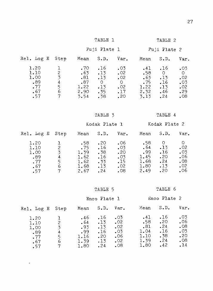
TABLE 1 TABLE 2
Fuji Plate 1 Fuji Plate 2
Rel. Log E Step Mean S.D. Var. Mean S.D. Var.
1.20 1 .70 .16 .03 .41 .16 .03
1.10 2 .63 .13 .02 .58 0 0
1.00 3 .81 .13 .02 .63 .13 .02
.89 4 .87 0 0 .75 .16 .03
.77 5 1.22 .13 .02 1.22 .13 .02
.67 6 2.90 .35 .17 2.32 .46 .29
.57 7 3.54 .38 .20 3.13 .24 .08
TABLE 3 TABLE 4
Kodak Plate 1 Kodak Plate 2
Rel. Log E Step Mean S.D. Var. Mean S.D. Var.
1.20 1 .58 .20 .06 .58 0 0
1.10 2 .75 .16 .03 .64 .13 .02
1.00 3 1.39 .38 .20 .99 .16 .03
.89 4 1.62 .16 .03 1.45 .20 .06
.77 5 1.62 .33 .15 1.68 .24 .08
.67 6 1.68 .13 .02 1.80 .13 .02
.57 7 2.67 .24 .08 2.49 .20 .06
TABLE 5 TABLE 6
Enco Plate 1 Enco Plate 2
Rel. Log E Step Mean S.D. Var. Mean S.D. Var.
1.20 1 .46 .16 .03
1.10 2 .64 .13 .02
1.00 3 .93 .13.02
.89 4 .99 .16 .03
.77 5 1.16 .20 .06
.676 1.39 .13
.02
.57 7 1.80 .24.08
.41 .16 .03
.58 .20 .06
.81 .24 .08
1.04 .16 .03
1.10 .38 .20
1.39 .24 .08
1.80 .42 .14

28
TABLE 7 TABLE 8
Howson-Algraphy Howson-Algraphy
Plate 1 Plate 2
Rel. Log E Step Mean S.D. Var. Mean S.D. Var.
1.20 1 0 0 0 0 0 0
1.10 2 .41 .15 .03 .52 .20 .06
1.003'
.46 .16 .03 .58 .17 .04
.89 4 .52 .14 .03 .75 .23 .08
.77 5 .63 .14 .03 .58 .24 .08
.67 6 .93 .20 .06 1.04 .28 .12
.57 7 1.10 .14 .03 1.45 .24 .08
.47 8 1.62 .28
TABLE 9
.12 2.03 .44
TABLE 10
.29
Hows on-Algraphy Hows on-Algraphy
Plate 3 Plate 4
Rel. Log E Step Mean S.D. Var. Mean S.D. Var.
1.20 1 0 0 0 .63 .14 .03
1.10 2 .46 .16 .03 .75 .16 .03
1.00 3 .58 .14 .03.81 .14 .03
.89 4 .63 .14 .031.22 .17 .06
.77 5 .93 .20 .06 1.51 .46 .32
.676 1.16 .28 .12 1.80 .40 .24
.57 7 1.40 .48 .332.32 .67 .82
.478 1.91 .33
.16
TABLE 11 TABLE 12
Howsion-Algr;aphy Howsson-Algraphy
Plate 5 Plate 6
Rel. Log E Step Mean S.D. Var. Mean S.D. Var
.57 7 1.74 .34 .17 1.33 .16 .03
.478 1.74 .17 .04
1.51 .24 .08
.31 9 1.51 .22 .071.62 .16 .03
.13 10 1.86 .50 .372.32 .20 .06
.02
-.08
11
12
2.61
2.84
.29
.32
.12
.16
2.26
3.19
.32
.29
.14
.12
-.18 13 2.84 .31 .143.42 .69 .66
29
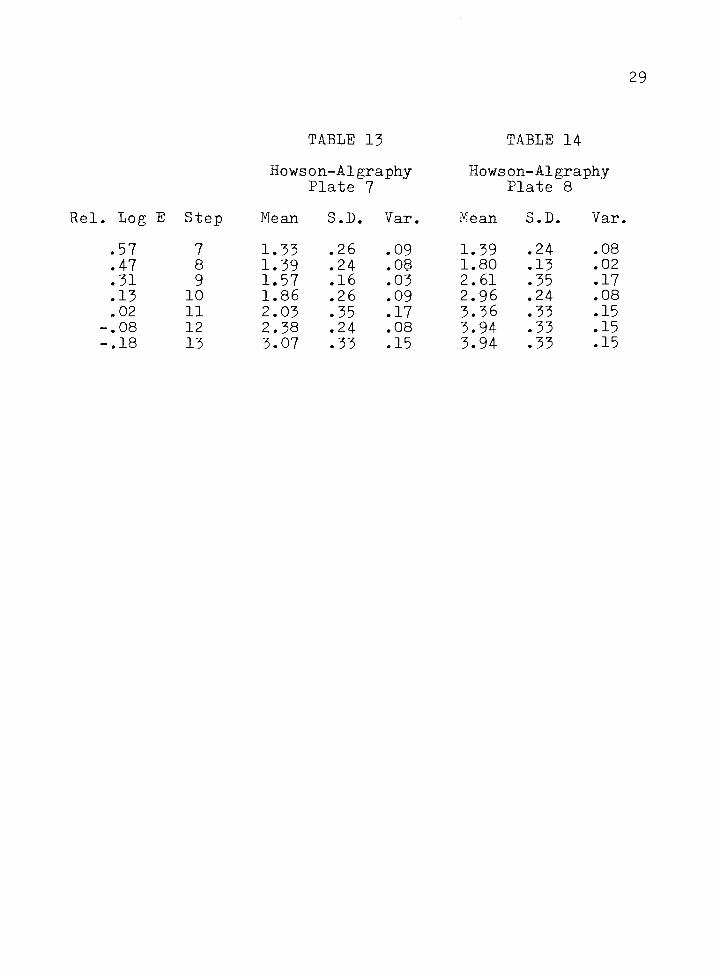
TABLE 13 TABLE 14
Howelon-Algraphy Hows ;on-Algraphy
Plate 7 Plate 8
el. Log E Step Mean S.D. Var. Mean S.D. Var
.57 7 1.33 .26 .09 1.39 .24 .08
.47 8 1.39 .24 .08 1.80 .13 .02
.31 9 1.57 .16 .03 2.61 .35 .17
.13 10 1.86 .26 .09 2.96 .24 .08
.02 11 2.03 .35 .17 3.36 .33 .15
-.08 12 2.38 .24 .08 3.94 .33 .15
-.18 13 3.07 .33 .15 3.94 .33 .15
30
CHAPTER VI
DISCUSSION OF RESULTS
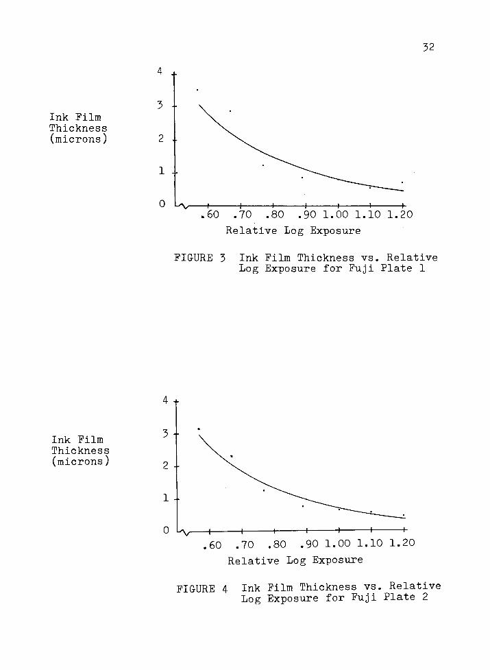
Once a viable technique providing sufficient inter-layer
contrast was established, measurement of ink film thicknesses
progressed smoothly. In all samples the ink film thickness
became progressively thicker from high to low exposure. (See
figures 3-16). A few plate samples (Howson-Algraphy Plate 2,
for example) showed thicknesses which initially increased,
decreased slightly for one step, and subsequently continued
increasing. This occurrence is attributed to variability
induced by at least two factors. All plates were hand
processed, and it is universally recognized that uneven
results can be generated by this procedure. The ink fountains
of the presses were not filled because of the low volume of
ink required. This second factor possibly contributed to the
variance of ink film thicknesses between control scales in
different locations on the same plate and between plates of
different manufacturers.
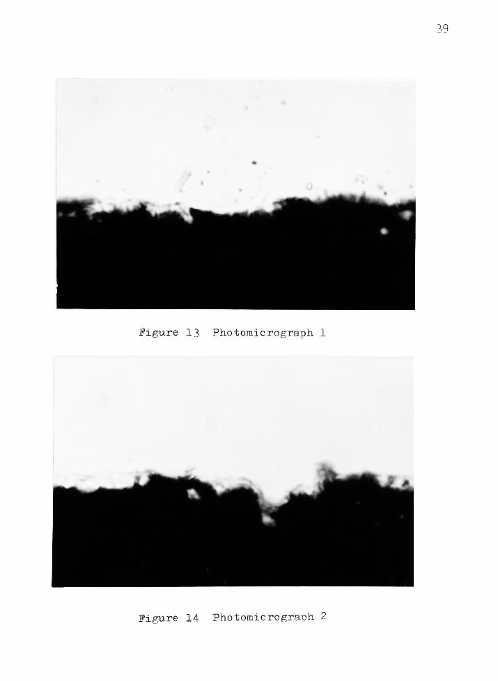
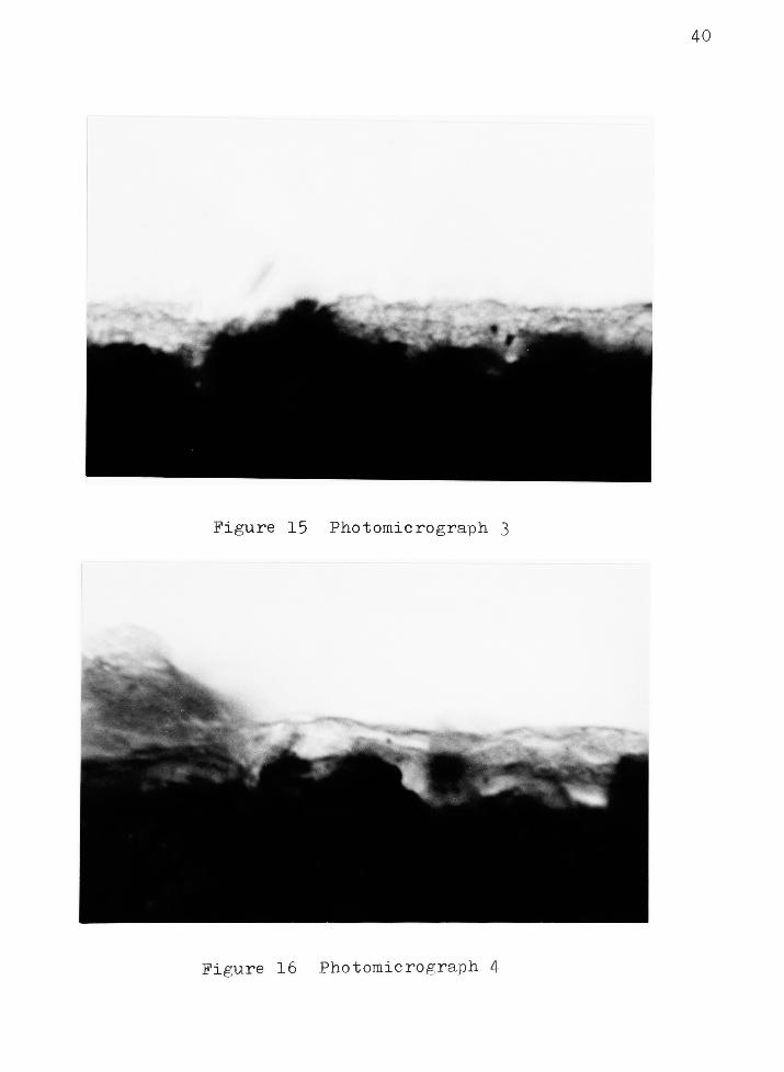
One of the most interesting phenomenon discovered was
the great variability of ink film thicknesses within each
control scale step of uniform density. This is immediately
t papparent in the photomicrographs. (See figures 13-16). As
ink film thickness increases there is a corresponding
increase in both standard deviation and variation. This
31
appears to be caused by the greater differences in topography
towards the surface of the plate and the consequential
differences in the light sensitive coating thickness caused
by the grain. This is readily observed in the photomicro
graphs .
All plates showed low contrast (-jhlcSne3S) in the
highlight areas. The Fuji, Enco, and Kodak plates all
markedly increased contrast in the shadow areas. Shadow con
trast in the Howson-Algraphy plates was much lower than in
the other plates. Observation of plate topography leads to
the following explanation of contrast characteristics.
The method used to grain a plate, and the resulting
plate topography, highly influence the relationship between
exposure and corresponding ink film thickness. This concept
can be understood by referring to the solubility plate model
in figure 17. Solubilization to level 1, representing a
shadow area, would produce little change on this plate. An
exposure causing solubilization to level 2 would be about the
same. Thus, in this plate, the shadow area would be low in
contrast. As exposure increased and solubilization reached a
greater proportion of grain peaks, the contrast would also
increase. Continued solubilization to level 3, in the
valleys of the grain, would gradually affect less and less
coating area and contrast would again decrease. Thus, how
the grain is formed - its depth, randomness, and shape -
highly influences the contrast and tone reproduction
32
Ink Film
Thickness
(microns)
4 +
3 -
2 .-
1 ..
0 L/v- -+-
.60 .70 .80 .90 1.00 1.10 1.20
Relative Log Exposure
FIGURE 3 Ink Film Thickness vs. Relative
Log Exposure for Fuji Plate 1
Ink Film
Thickness
(microns)
4 +
3
2 -
1 --
o Lv-
.60 .70 .80 .90 1.00 1.10 1.20
Relative Log Exposure
FIGURE 4 Ink Film Thickness vs. Relative
Log Exposure for Fuji Plate 2
33
Ink Film
Thickness
(microns)
4
3
2 --
1 ..
0 L-v.60 .70 .80 .90 1.00 1.10 1.20
Relative Log Exposure
FIGURE 5 Ink Film Thickness vs. Relative
Log Exposure for Kodak Plate 1
Ink Film
Thickness
(microns)
4
3 -
2 --
1 --
.60 /70 TSo .90 l.Ao l.io i.io
Relative Log Exposure
FIGURE 6 Ink Film Thickness vs. Relative
Log Exposure for Kodak Plate 2
34
Ink Film
Thickness
(microns)
4 +
3
2 -
1 ..
0 U/V, 1 1 1 1 1 1 fcr.60 .70 .80 .90 1.00 1.10 l720
Relative Log Exposure
FIGURE 7 Ink Film Thickness vs. Relative
Log Exposure for Enco Plate 1
Ink Film
Thickness
(microns)
4 --
3 -
2 --
1-.
0 "A/-
760 770 ^80 .90 1.00 1.10 1.20
Relative Log Exposure
FIGURE 8 Ink Film Thickness vs. Relative
Log Exposure for Enco Plate 2
35
u
o
H
CD
u
CO
o
Ph
XK)
O
hq
CD
>H
-P LTV
a
i-tog
CU
P, rH
CO
CO CD
?3CO rH
co PhCD
o
en
H
>5
Pt
a)
rH
<t!
I
o
CO
o
H M
CTt
fa
P=i
H
fin
co-
E co CO
H CD SH fi o
pq J* eH
o O
,*-H H
fl ^ EM EH
36
o
*
rH
oT-I
UO
=H
CD
f-l
CO
O
ft
XPa.
bO
O 0
"O^
<D CD
fn >P5 -H
co -P UD
O CTJ
o ft rHog
r- X CD
W P-1 CnJ
bjj CO
O CO CD
M
co H.0
CD
LTN. > to PM. H CD
-P fl >J0? .*,
rH O ft<D H C\j
0 <A ^ f-l.f^i tH bC
O X 3=
-H a 0
*
0rH
O pa
-rH
1 Ct)
H
pq
CO-
E co CO
H CD
H S 0
pq ^ fn
0 O
X -H H
, EH
EH'
37
o
rH
rH
o
<H
CD
o 2CO
o
rH ft
Xpa
bO
O o
cn nq
CD CD
rH >3 H
CO p t-
o ci
O ft HogD- X CD
ca PtJ rA
hfl CO
O CO CD
^ !>-P
Ctf
CO rHO CD
LP > CO P4H CD
P ti >>05 XArH o ft
CD H CTJ
o cn ^ ^CH^ EH bO
c ^H o
urn
rH
rH
o parH CC
1
pq
EH
CO
CO CO
o
0
ePq x u
o o
X -H -H
^5 EH EH-^
38
ot<->
urH O
CD
UO 2rH co
o
rH ft
X
pa
bO
o O
cn i-q
CD CD
u >3 H
CO -P 00o 05
o ft rHcSr- X CD
M cr; h^
bO CO
o CO CD
r-q>+>
o 05LTn CD CO rH
> CO PhH CD
P C tCTj .*,
rH o ftCD H crj
o ^ eH
Ch"> EH bO.
C x >rH o
CM
H
O parH rt
1
P3
M
Pq
CO'
E co co
H CD
H J3
pq ^o o
X "H -H
, EHH EH^
O
rH
39
Figure 13 Photomicrograph 1
Figure 14 Photomicrograph 2
40
Figure 15 Photomicrograph 3
Figure 16 Photomicrograph 4
41
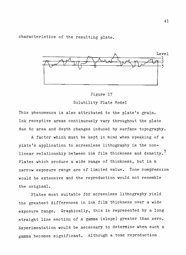
characteristics of the resulting plate,
Figure 17
Solubility Plate Model
This phenomenon is also attributed to the plate's grain.
Ink receptive areas continuously vary throughout the plate
due to area and depth changes induced by surface topography.
A factor which must be kept in mind when speaking of a
plate's application to screenless lithography is the non-
linear relationship between ink film thickness and density.
Plates which produce a wide range of thickness, but in a
narrow exposure range are of limited value. Tone compression
would be extensive and the reproduction would not resemble
the original.
Plates most suitable for screenless lithography yield
the greatest differences in ink film thickness over a wide
exposure range. Graphically, this is represented by a long
straight line section of a gamma (slope) greater than zero.
Experimentation would be necessary to determine when such a
gamma becomes significant. Although a tone reproduction
42
study comparing printed density to density of the original
would be necessary to determine the useful exposure range,
exposures which do not produce a change in ink film thickness
are not useful for tone reproduction purposes. The smallest
exposure required to produce a change in ink film thickness
is called the speed point and determines overall plate
exposure.
43
FOOTNOTES FOR CHAPTER VI
The sharpness in these photomicrographs was severely
limited. Edge rounding during the cross-sectioning operation
and a shallow depth of focus at 1000X initial magnification
induced a limited depth of focus in the final prints. These
photomicrographs are intended to illustrate concepts.
Dynamic focusing was necessary to accurately measure ink film
thickness, something unobtainable in a still photograph.
2Ibid.
^J.A.C. Yule, Principles of Color Reproduction, (New
York: John Wiley & Sons, Inc., 1967), p. 123.
44
CHAPTER VII
SUMMARY AND CONCLUSION
It has been known for some time that grain in litho
graphic plates makes screenless printing possible. The
purpose of this study was to determine how this grain influ
ences the continuous tone capability of these plates. This
capability is due to theplates'
ability to produce a
variable ink film thickness. The variable ink film was shown
to occur not only from areas of high to low exposure, but
also within areas of uniform exposure. These variations are
due to topographic changes caused by the plate grain.
It is hoped that this research will define more clearly
exactly what screenless lithography is and how it works. A
comprehensive understanding of the process is necessary to
assure optimum results and the continued use of screenless
lithography.
45
CHAPTER VIII
RECOMMENDATIONS FOR FURTHER RESEARCH
The development of this reliable, accurate method for
determining ink film thicknesses on screenless printing plates
opens many possibilities for further investigations. Applica
tion of this technique on negative working plates utilizing
the conventional halftone process is what immediately comes to
mind. It is possible that ink film thickness varies on these
plates and one might determine relationships between dot size,
ink film thickness, and tone reproduction.
Application of a scanning microdensitometer for achieving
more accurate ink film thickness profiles by evaluating the
entire plate surface could lead to a better understanding of
the relationship between density and ink film thickness.
Optimization of the capabilities inherent in screenless
printing plates is unquestionably influenced by the graining
of theplates'
surface. Research into methods for producing
a finer, yet deeper, randomly grained plate could provide a
plate with a greater density range.Sumner-Williams'
discon
tinued wipe-on positive plates achieved an excellent random
grain with a sandblasting technique. No one at this time
produces a plate grained in this manner.

46
GENERAL REFERENCE
"How to do continuous tone lithography."Printing Production,
December 1968.
"Screenless in Bletchley."Lithoprinter. October 1977.
Brandon, D.G. Modern Techniques in Metallography. New York:McGraw-Hi11, 1966.
Fink, W.L. et al. Physical Metallurgy of Aluminum Alloys.Cleveland: American Society for Metals, 1949.
Gifkins, R.C. Optical Microscopy of Metals. New York:
American Elsevier Pub. Co., Inc., 1970.
Kehl, G.L. The Principles of Metallographic LaboratoryPractice. New York: McGraw-Hill, 1949.
Lawson, L.E. "Control Scales and Grained Positive Plates."
TAGA Proceedings 1980.
Loveland, R.P. Photomicrography a Comprehensive Treatise,Vol. 1. New York: John Wiley & Sons, Inc., 1970.
Materazzi, Dr. Albert R. "Screenless Printing."Graphic
Arts Monthly. January 1975.
Montgomery, Alex. "Integral Random Dot."Australasian
Printer. August 1978.
Pearson, A.W. and Parker, C.A. "The Influence of Plate
Topography Upon Print Quality inLithography."
TAGA
Proceedings 1981.
Powers, John H. "Surface Area Measuring Test for Grained
Aluminum LithographicPlates."
TAGA Proceedings 1974.
Rochow, T.G. and Rochow, E.G. An Introduction to Microscopy
by Means of Light. Electrons, X-ray, or Ultrasound.
New York: Plenum Press, 1978.
Smith, A.H. "The Theory of Screenless Lithography in
Relation to Plate GrainStructure."
The Journal of
Photographic Science. July/August 1978.
Traber, H.A. "The Microscope as aCamera."
New York:
Amphoto. 1971.
47
Manufacturer
Ronico
Ronico
Ronico
Ronico
Dayglo
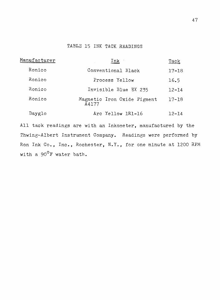
TABLE 15 INK TACK READINGS
Ink Tack
Conventional Black 17-18
Process Yellow 16.5
Invisible Blue EX 235 12-14
Magnetic Iron Oxide Pigment 17-18
A4177
Arc Yellow 1R1-16 12-14
All tack readings are with an Inkometer, manufactured by the
Thwing-Albert Instrument Company. Readings were performed by
Ron Ink Co., Inc., Rochester, N.Y., for one minute at 1200 RPM
with a 90 F water bath.
48
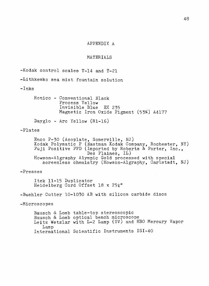
APPENDIX A
MATERIALS
-Kodak control scales T-14 and T-21
-Lithkemko sea mist fountain solution
-Inks
Ronico - Conventional Black
Process Yellow
Invisible Blue EX 235
Magnetic Iron Oxide Pigment (53%) A4177
Dayglo - Arc Yellow (Rl-16)
-Plates
Enco P-30 (Azoplate, Somerville, NJ)Kodak Polymatic P (Eastman Kodak Company, Rochester, NY)Fuji Positive FPD (Imported by Roberts & Porter, Inc.,
Des Plaines, IL)
Howson-Algraphy Alympic Gold processed with special
screenless chemistry (Howson-Algraphy, Carlstadt, NJ)
-Presses
Itek 11-15 Duplicator
Heidelberg Cord Offset 18 x25i"
-Buehler Cutter 10-1030 AB with silicon carbide discs
-Microscopes
Bausch & Lomb table-top stereoscopic
Bausch & Lomb optical bench microscope
Leitz Wetzlar with L-2 Lamp (UV) and HBO Mercury Vapor
LampInternational Scientific Instruments ISI-40
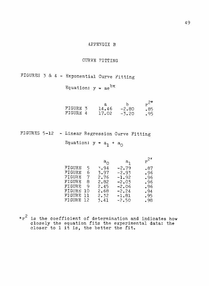
APPENDIX B
CURVE FITTING
FIGURES 3 & 4 - Exponential Curve Fitting
Equation: y = ae
49
FIGURE 3 14.46 -2.80
FIGURE 4 17.02 -3.20
.85
.95
FIGURES 5-12 Linear Regression Curve Fitting
Equation: y= a, +
a0
2*
a0 "1i.
FIGURE 5 ^.94 -2.79 .87
FIGURE 6 3.97 -2.93 .96
FIGURE 7 2.76 -1.92 .96
FIGURE 8 2.82 -2.03 .96
FIGURE 9 2.45 -2.06 .96
FIGURE 10 2.68 -2.24 .94
FIGURE 11 2.32 -1.81 .95
FIGURE 12 3.41 -2.50 .98
is the coefficient of determination and indicates how
closely the equation fits the experimental data: the
closer to 1 it is, the better the fit.