Embed Size (px)
Citation preview
Journal of Mechanical Science and Technology 25 (3) (2011) 655~662
www.springerlink.com/content/1738-494x DOI 10.1007/s12206-011-0109-5
Analysis of guide modes in vertical hot ring rolling and their effects on the ring’s
dimensional precision using FE method† Xiaokai Wang1 and Lin Hua1,2,*
1School of Materials Science and Engineering, Wuhan University of Technology, Wuhan 430070, China 2Hubei Key Laboratory of Advanced Technology of Automotive Parts, Wuhan 430070, China
(Manuscript Received August 27, 2010; Revised November 10, 2010; Accepted November 22, 2010)
----------------------------------------------------------------------------------------------------------------------------------------------------------------------------------------------------------------------------------------------------------------------------------------------
Abstract In the vertical hot ring rolling (VHRR) process, roundness, outer radius, and width spread are three important indexes to the formed
ring’s dimensional precision. In this paper, features of the guide modes of the VHRR process, such as single fixed guide mode (SFGM) and single follow-up guide mode (SFUGM), are analyzed to investigate their effects on the ring’s dimensional precision. The geometrical models of all the guide modes are then established and reliable three-dimensional coupled thermal-mechanical elastic-plastic FE models of the VHRR process are developed in ABAQUS/Explicit. Some key technologies, such as the guide roller’s motion control, are rea-sonably dealt with. The research results show that: (1) The roundness of the rings rolled by SFUGM is obviously superior to that of the ring rolled by SFGM. (2) With the same feed amount, the outer radius of the ring rolled by SFGM is always larger than that of the rings rolled by SFUGM. (3) During the rolling process of the ring rolled by SFGM, severe eccentricity will exist at the ring’s center, which is not obvious in the rolling process of the ring rolled by SFUGM. (4) The average value of width spread of the ring rolled by SFGM is slightly larger than that of the rings rolled by SFUGM. The research results can yield an understanding of some phenomena in the VHRR process. The modeling methods presented in this paper have general significance in the study of the VHRR process of the ring with com-plex profile.
Keywords: Vertical hot ring rolling; FE modeling; Dimensional precision; Guide mode; Roundness error; Eccentricity ---------------------------------------------------------------------------------------------------------------------------------------------------------------------------------------------------------------------------------------------------------------------------------------------- 1. Introduction
Ring rolling is an advanced metal forming technique to manufacture precise seamless rings with various dimensions, shapes, and materials [1]. A guide roller is essential to the ring rolling mill, which can keep the rolling process steady and maintain the ring’s circularity. In practical production, hori-zontal hot ring rolling (HHRR) mills [2] are usually equipped with a pair of guide rollers controlled by a synchronous hy-draulic ram and a linkage mechanism (Fig. 1(a)) Cold ring rolling (CRR) mills [3] are usually installed with one guide roller whose position can be regulated by a level (Fig. 1(b)). Various guide modes are employed in vertical hot ring rolling (VHRR). Generally, VHRR mills adopt single guide modes classified into two types: single fixed guide mode (SFGM) and single follow-up guide mode (SFUGM) in which the guide roller can adjust its position as the ring grows. The SFUGM can be further divided into three types according to
the moving path of the guide roller: single straight guide mode (SSGM), single upward arc guide mode (SUGM), and single downward arc guide mode (SDGM).
To date, much work is being done about the effects of dif-ferent technological parameters, such as material properties, feeding rate, feeding amount, and rollers’ dimensions on the ring’s deformation mechanism. Moon et al. [4] applied rigid-viscoplastic finite element method to investigate polygonal-shaped defects that occur during ring rolling. Yeom et al. [5] investigated the ring-rolling design for a large-scale ring prod-uct of Ti–6Al–4V alloy by calculation method and FEM analysis. Hua et al. [6] studied the plastic penetration of groove ball-section ring. Wang et al. [7] developed a coupled thermo-mechanical FE model of HHRR under ABAQUS environment, and studied the blank size effects on the uni-formity of strain and temperature distributions during hot roll-ing of titanium. Until now, literature on the guide modes in VHRR and their effects on the ring’s dimension are relatively minimal. Forouzan et al. [8] adopted thermal spokes instead of the role of guide rolls, and removed the guide rolls from the ring rolling model, so it was difficult to reflect the contact between the guide rolls and the ring exactly. Hua et al. [3, 9]
†This paper was recommended for publication in revised form by Associate EditorYoung-seog Lee
*Corresponding author. Tel.: +86 27 87653249, Fax.: +82 27 87168391 E-mail address: [email protected]
© KSME & Springer 2011
656 X. Wang and L. Hua / Journal of Mechanical Science and Technology 25 (3) (2011) 655~662
obtained the movement rules of the single follow-up guide roller for CRR and HHRR. Wang et al. [10] developed a pro-gram to control the complex movements of the guide rollers and realized the virtual radial-axial rolling of profiled rings based on the LS-DYNA code. However, the coupled thermal-mechanical effect was not considered. More recently, Li et al. [11] used surface-based fluid cavities and connector element technologies in ABAQUS to model the guide mechanism, but it was not applicable to the rings rolled by a single follow-up guide mode. In practical production, various guide modes are adopted in the VHRR process. Some problems, such as the selection of guide mode and the effects of guide modes on product quality are still unclear. In this study, by referring to the guide modes of CRR and HHRR, the features of four guide modes of VHRR process are analyzed. On this basis, three-dimensional (3D) models are established to verify the four guide modes under ABAQUS environment. Finally, in-vestigation and comparison are conducted with respect to the ring’s dimensional precision, such as roundness error, eccen-tricity, outer radius, wall thickness, and width spread. The purpose of this paper is threefold: to establish reliable geomet-rical modes for various guide modes of VHRR process, to reveal the effect of various guide modes on the ring’s dimen-sional precision, and to indicate that SDGM is more appropri-ate than the other three guide modes for VHRR process to produce more precise ring products.
2. Guide modes of VHRR
2.1 Single fixed guide mode (SFGM)
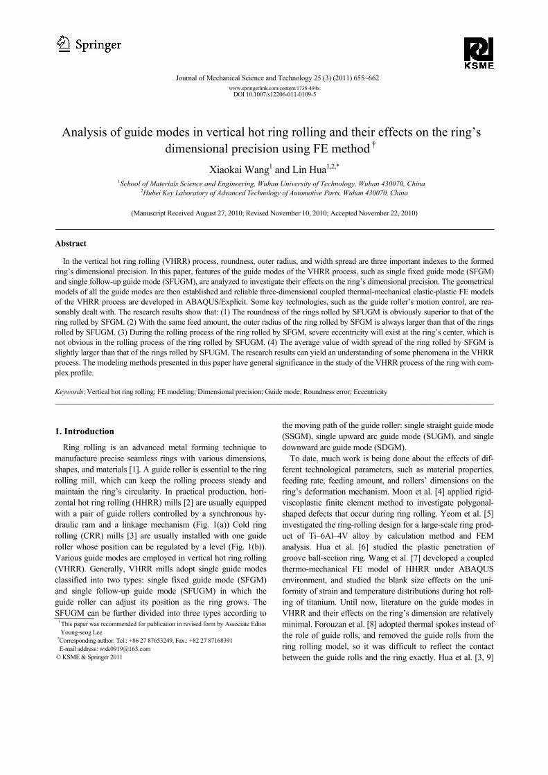
Fig. 2 shows the SFGM of the conventional D51 vertical ring rolling mill. The guide roller must be preset before the rolling process according to the size of the formed ring. The guide roller is mounted by the fixed stay and nut screw during the rolling process. SFGM possesses a simple structure, is convenient to manufacture, and cost-efficient. However, it cannot produce a larger size ring due to its structural limitation. Moreover, an offset will be created at the ring’s center under the guide roller’s pressure. This phenomenon will be investi-gated in detail in subsequent sections. 2.2 Single straight guide mode (SSGM)
Fig. 3 is the schematic diagram of the SSGM structure of
VHRR and its force condition. For this guide mode, the direc-tions of the guide force Fd and the hydraulic force Fh are dif-ferent, which may cause the component force Fdx on the mov-ing direction of the guide roller to be smaller than the hydrau-lic force Fh. This could prevent the ring from pushing the guide roller back, and thus, an offset like SFGM would appear. Furthermore, the other component force Fdy can lead to bias load. This would wear out the inner wall of the hydraulic ram.
The geometrical model of SSGM is then established (Fig. 4). The origin of the coordinate system is set at the initial position of the guide roller’s center. The moving path of the guide roller is assumed at an inclination angle of β degree to the X axis. To simplify the problem, an auxiliary circle with the same center as the ring is assumed, and its radius is equal to the sum of the radius of ring and guide roller. Consequently, the crossing point of the auxiliary circle and the guide roller’s moving path is the position of the guide roller’s center.
According to Fig. 4, (C, D) is the initial center coordinate of the ring blank. Points (x, y) and (m, n) are the instantaneous center coordinate of the guide roller and the deformed ring, respectively. The following equation set can thus be obtained:
Hydraulic ram
Driving roller Mandrel
roller
Guide rollerRing
Fixed hinge
Guide roller arm
νnφFixed
hinge
Guide roller
Mandrel roller
Driving roller
Ring
Guide roller arm
(a) The guide mode of HHRR (b) The guide mode of CRR Fig. 1. The guide modes of HHRR and CRR.
νn
Driving roller
Mandrel roller Guide
roller
Ring
Fixed stay
Nut screw
Guide roller arm
Fixed hinge
Fig. 2. SFGM structure of VHRR.
νn
Driving roller
Mandrel roller Guide
roller
Ring Guide roller arm
Hydraulic ram
Fd
Fh
Fdx
FdyStraight line
Fig. 3. SSGM structure of VHRR and force condition.
X
Y
o
R0
r0
h
o1
o2
Rt
β Rd
Rn
(C,D)
(m,n)
Fig. 4. Geometrical model of SSGM.
X. Wang and L. Hua / Journal of Mechanical Science and Technology 25 (3) (2011) 655~662 657
( ) ( ) ( )⎩⎨⎧
•=+=−+−
xyRRnymx dt
βtan
222 (1)
where Rt is the outer radius of the ring at time t based on the principle of volume constancy in plastic deformation [1]. Rd is the outer diameter of the guide roller and v is the feed rate of the driving roller [3].
⎟⎟⎠
⎞⎜⎜⎝
⎛−−+
−−−
= vtrRvtrR
rRRt 0000
20
20
21 (2)
where R0 and r0 are the outer radius and inner radius of the ring blank, respectively.
The instantaneous center coordinate (x, y) of the guide roller can be expressed by
( )
( )⎪⎪
⎩
⎪⎪
⎨
⎧
•+
−−+•++•+=
+−−+•++•+
=
ββ
βββ
ββββ
tantan1
tantan2tan
tan1tantan2tan
2
2222
2
2222
nmEmnEnmy
nmEmnEnmx
(3) where 0, ,t d tE R R m C n R R D vt= + = = − − + . (4) 2.3 Single arc guide mode
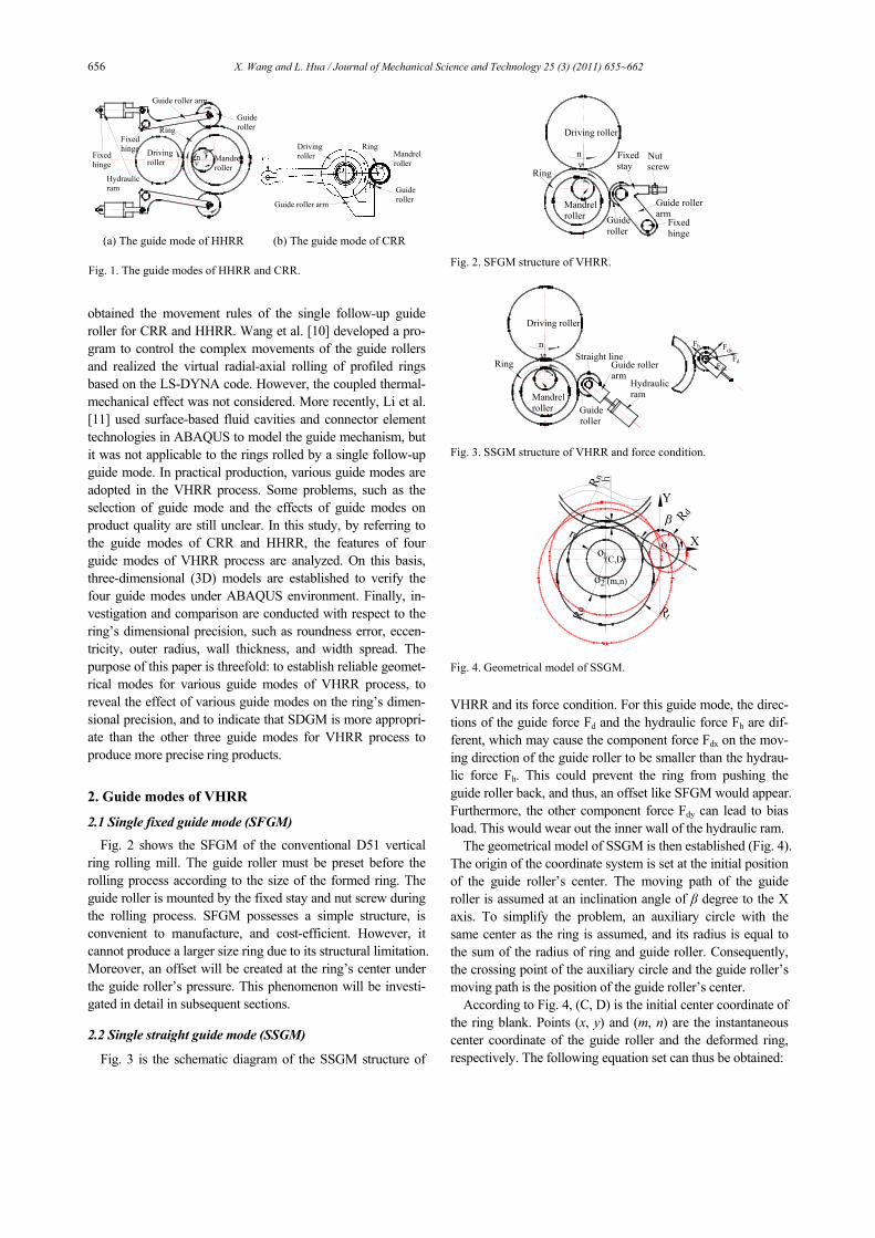
The arc guide mode can be classified into two types: SDGM, in which the guide roller arm is fixed at the upper right of the mandrel roller and the guide roller moves in a downward arc (Fig. 5 (a)); and SUGM, in which the guide roller arm is fixed at the lower right of the mandrel roller and the guide roller moves in an upward arc (Fig. 5 (b)). It is ad-
vantageous for the two guide modes to keep the rolling proc-ess smooth because of the arc movement of the guide roller. In addition, bias load will not occur due to the links and hinges of the guide structure.
Similarly, the geometrical model of SDGM and SUGM can also be set up (Fig. 6).
The coordinate system and geometrical parameters are iden-tical to those mentioned in 2.2. Assuming that Ra is the length of the guide roller arm, the coordinate of the fixed hinge of the guide roller arm is (U, V). The following equation set can then be obtained:
( ) ( ) ( )( ) ( )
2 2 2t d
2 2 2a
x - m + y - n = R + R
x -U + y -V = R
⎧⎪⎨⎪⎩ .
(5)
The expression of the guide roller’s movement track can be
gained by solving Eq. (5). The solution is very complex but the numerical solution of Eq. (5) can be calculated when the feed rate and the value of the geometrical parameters are known.
3. 3D coupled thermo-mechanical FE model of VHRR
The 3D coupled thermo-mechanical elastic-plastic FE model is set up in ABAQUS/Explicit (Fig. 8(a)). The roller dimensions refer to the actual D51-350 VHRR mill [1], and the processing parameters are according to the practical work condition (Table 1). The contact pairs are defined between the ring and the rollers. Friction and contact heat conduction exist at the interface of each contact pair. The rectangular section ring is considered as the subject investigated.
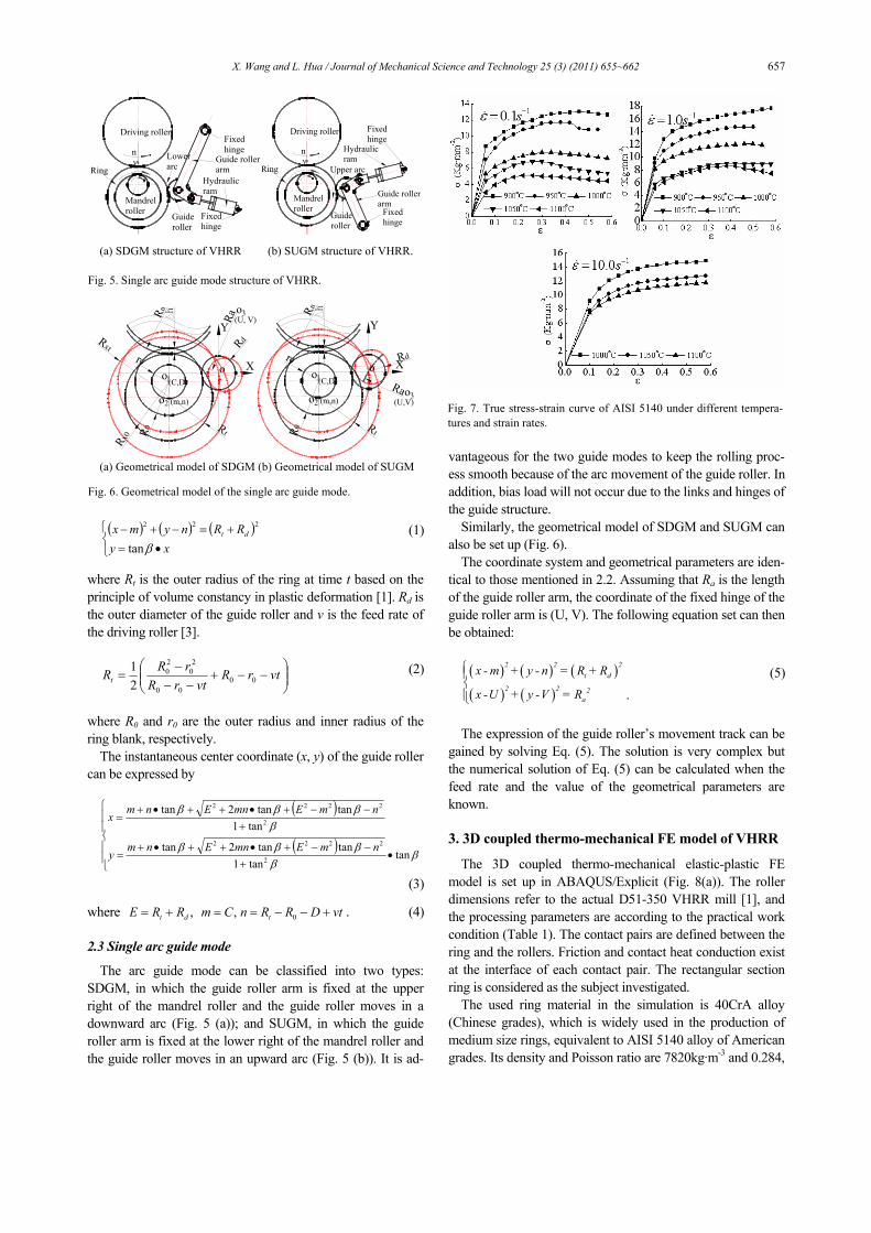
The used ring material in the simulation is 40CrA alloy (Chinese grades), which is widely used in the production of medium size rings, equivalent to AISI 5140 alloy of American grades. Its density and Poisson ratio are 7820kg·m-3 and 0.284,
νn
Driving roller
Mandrel roller Guide
roller
Ring
Fixed hinge
Hydraulic ram
Guide roller arm
Fixed hinge
Lower arc ν
n
Driving roller
Mandrel roller
Guide roller
Ring
Fixed hinge
Hydraulic ram
Guide roller arm
Fixed hinge
Upper arc
(a) SDGM structure of VHRR (b) SUGM structure of VHRR. Fig. 5. Single arc guide mode structure of VHRR.
X
Y
o
R0
r0
h
o1
o2
Rt
Rd
Rx0
Rxt
Rn
(C,D)
(m,n)
Ra(U, V)o3
X
Y
o
R0
r0
h
o1
o2
Rt
Rd
Rn
(C,D)
(m,n)Ra(U,V)
o3
(a) Geometrical model of SDGM (b) Geometrical model of SUGM Fig. 6. Geometrical model of the single arc guide mode.
Fig. 7. True stress-strain curve of AISI 5140 under different tempera-tures and strain rates.
658 X. Wang and L. Hua / Journal of Mechanical Science and Technology 25 (3) (2011) 655~662
respectively. The constitutive model established by Wang et al. [12] is adopted. The obtained stress-strain curves under differ-ent temperature and strain rate are given in Fig. 7.
The motion control over guide roller plays a critical role in developing the FE model of VHRR. Based on adaptive con-trol technologies mentioned by Xu et al. [13] and Hua et al. [3], the movement of guide roller for the VHRR simulation can be realized in ABAQUS/Explicit [Fig. 8 (b)]. The move-ment of the guide roller can be divided into X and Y directions, represented as dx and dy, respectively. To SFGM, dx and dy are set as zero. To SFUGM, dx and dy are set according to the solutions of Eqs. (1) and (5), respectively. Hence, the guide roller motion can be precisely realized.
The whole rolling process takes six seconds, which can be divided into two stages, namely, feeding stage lasting for five seconds and finishing stage lasting for one second.
4. Results and discussion
4.1 Roundness error
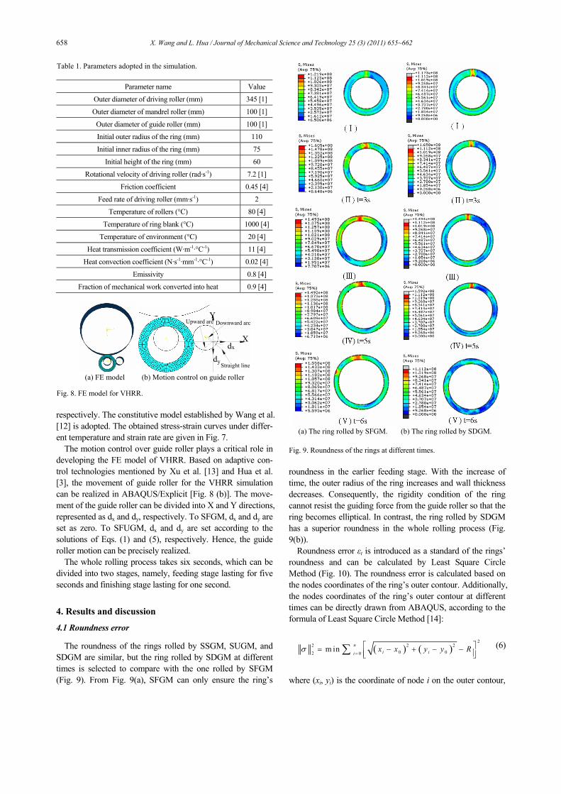
The roundness of the rings rolled by SSGM, SUGM, and SDGM are similar, but the ring rolled by SDGM at different times is selected to compare with the one rolled by SFGM (Fig. 9). From Fig. 9(a), SFGM can only ensure the ring’s
roundness in the earlier feeding stage. With the increase of time, the outer radius of the ring increases and wall thickness decreases. Consequently, the rigidity condition of the ring cannot resist the guiding force from the guide roller so that the ring becomes elliptical. In contrast, the ring rolled by SDGM has a superior roundness in the whole rolling process (Fig. 9(b)).
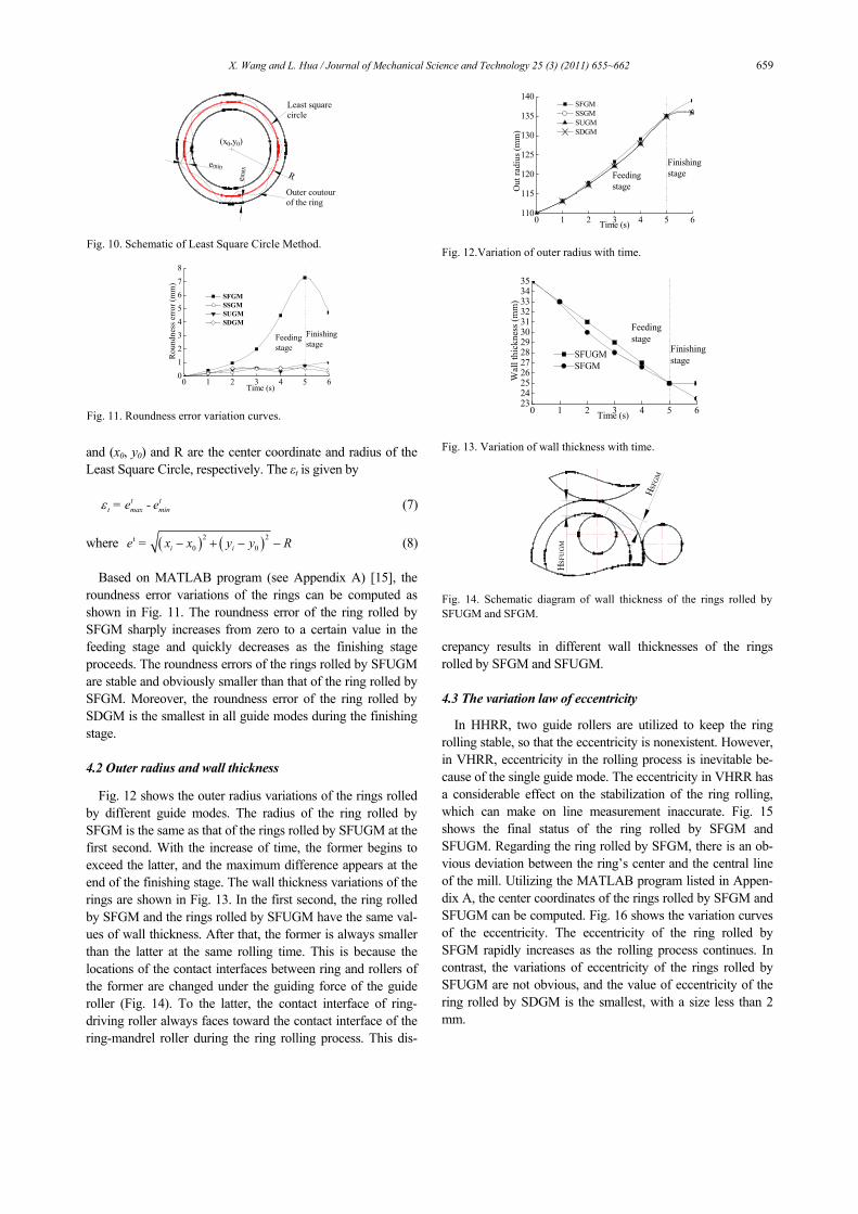
Roundness error εt is introduced as a standard of the rings’ roundness and can be calculated by Least Square Circle Method (Fig. 10). The roundness error is calculated based on the nodes coordinates of the ring’s outer contour. Additionally, the nodes coordinates of the ring’s outer contour at different times can be directly drawn from ABAQUS, according to the formula of Least Square Circle Method [14]:
( ) ( )2
2 2 20 02 0
m in ni ii
x x y y Rσ=⎡ ⎤= − + − −⎢ ⎥⎣ ⎦∑ (6)
where (xi, yi) is the coordinate of node i on the outer contour,
Table 1. Parameters adopted in the simulation.
Parameter name Value
Outer diameter of driving roller (mm) 345 [1]
Outer diameter of mandrel roller (mm) 100 [1]
Outer diameter of guide roller (mm) 100 [1]
Initial outer radius of the ring (mm) 110
Initial inner radius of the ring (mm) 75
Initial height of the ring (mm) 60
Rotational velocity of driving roller (rad·s-1) 7.2 [1]
Friction coefficient 0.45 [4]
Feed rate of driving roller (mm·s-1) 2
Temperature of rollers (°C) 80 [4]
Temperature of ring blank (°C) 1000 [4]
Temperature of environment (°C) 20 [4]
Heat transmission coefficient (W·m-1·°C-1) 11 [4]
Heat convection coefficient (N·s-1·mm-1·°C-1) 0.02 [4]
Emissivity 0.8 [4]
Fraction of mechanical work converted into heat 0.9 [4]
X
Y
dx
dy
Upward arc Downward arc
Straight line (a) FE model (b) Motion control on guide roller Fig. 8. FE model for VHRR.
(a) The ring rolled by SFGM. (b) The ring rolled by SDGM. Fig. 9. Roundness of the rings at different times.
X. Wang and L. Hua / Journal of Mechanical Science and Technology 25 (3) (2011) 655~662 659
and (x0, y0) and R are the center coordinate and radius of the Least Square Circle, respectively. The εt is given by
t t
t max min= e - eε (7)
where ( ) ( )2 2t0 0i ie = x x y y R− + − − (8)
Based on MATLAB program (see Appendix A) [15], the
roundness error variations of the rings can be computed as shown in Fig. 11. The roundness error of the ring rolled by SFGM sharply increases from zero to a certain value in the feeding stage and quickly decreases as the finishing stage proceeds. The roundness errors of the rings rolled by SFUGM are stable and obviously smaller than that of the ring rolled by SFGM. Moreover, the roundness error of the ring rolled by SDGM is the smallest in all guide modes during the finishing stage.
4.2 Outer radius and wall thickness
Fig. 12 shows the outer radius variations of the rings rolled by different guide modes. The radius of the ring rolled by SFGM is the same as that of the rings rolled by SFUGM at the first second. With the increase of time, the former begins to exceed the latter, and the maximum difference appears at the end of the finishing stage. The wall thickness variations of the rings are shown in Fig. 13. In the first second, the ring rolled by SFGM and the rings rolled by SFUGM have the same val-ues of wall thickness. After that, the former is always smaller than the latter at the same rolling time. This is because the locations of the contact interfaces between ring and rollers of the former are changed under the guiding force of the guide roller (Fig. 14). To the latter, the contact interface of ring-driving roller always faces toward the contact interface of the ring-mandrel roller during the ring rolling process. This dis-
crepancy results in different wall thicknesses of the rings rolled by SFGM and SFUGM.
4.3 The variation law of eccentricity
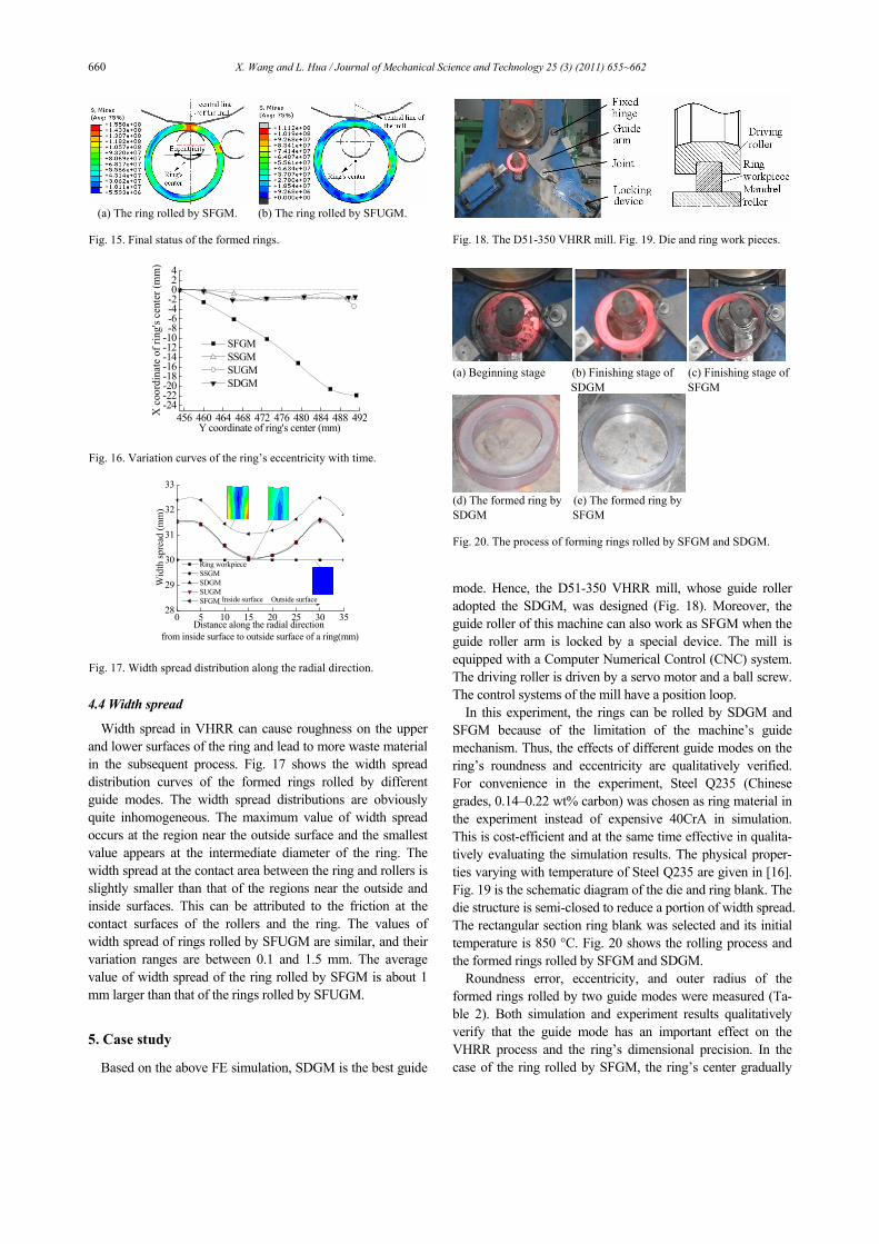
In HHRR, two guide rollers are utilized to keep the ring rolling stable, so that the eccentricity is nonexistent. However, in VHRR, eccentricity in the rolling process is inevitable be-cause of the single guide mode. The eccentricity in VHRR has a considerable effect on the stabilization of the ring rolling, which can make on line measurement inaccurate. Fig. 15 shows the final status of the ring rolled by SFGM and SFUGM. Regarding the ring rolled by SFGM, there is an ob-vious deviation between the ring’s center and the central line of the mill. Utilizing the MATLAB program listed in Appen-dix A, the center coordinates of the rings rolled by SFGM and SFUGM can be computed. Fig. 16 shows the variation curves of the eccentricity. The eccentricity of the ring rolled by SFGM rapidly increases as the rolling process continues. In contrast, the variations of eccentricity of the rings rolled by SFUGM are not obvious, and the value of eccentricity of the ring rolled by SDGM is the smallest, with a size less than 2 mm.
emin
emax
(x0,y0)
R
Least square circle
Outer coutour of the ring
Fig. 10. Schematic of Least Square Circle Method.
0 1 2 3 4 5 6012345678
Time (s)
Rou
ndne
ss e
rror
(mm
)
SFGM SSGM SUGM SDGM
Finishing stage
Feeding stage
Fig. 11. Roundness error variation curves.
0 1 2 3 4 5 6110
115
120
125
130
135
140
Finishing stageFeeding
stage
SFGM SSGM SUGM SDGM
Out
radi
us (m
m)
Time (s) Fig. 12.Variation of outer radius with time.
0 1 2 3 4 5 623242526272829303132333435
Finishing stage
Feeding stage
Wal
l thi
ckne
ss (m
m)
Time (s)
SFUGMSFGM
Fig. 13. Variation of wall thickness with time.
HSFG
M
HSF
UG
M
Fig. 14. Schematic diagram of wall thickness of the rings rolled by SFUGM and SFGM.
660 X. Wang and L. Hua / Journal of Mechanical Science and Technology 25 (3) (2011) 655~662
4.4 Width spread
Width spread in VHRR can cause roughness on the upper and lower surfaces of the ring and lead to more waste material in the subsequent process. Fig. 17 shows the width spread distribution curves of the formed rings rolled by different guide modes. The width spread distributions are obviously quite inhomogeneous. The maximum value of width spread occurs at the region near the outside surface and the smallest value appears at the intermediate diameter of the ring. The width spread at the contact area between the ring and rollers is slightly smaller than that of the regions near the outside and inside surfaces. This can be attributed to the friction at the contact surfaces of the rollers and the ring. The values of width spread of rings rolled by SFUGM are similar, and their variation ranges are between 0.1 and 1.5 mm. The average value of width spread of the ring rolled by SFGM is about 1 mm larger than that of the rings rolled by SFUGM.
5. Case study
Based on the above FE simulation, SDGM is the best guide
mode. Hence, the D51-350 VHRR mill, whose guide roller adopted the SDGM, was designed (Fig. 18). Moreover, the guide roller of this machine can also work as SFGM when the guide roller arm is locked by a special device. The mill is equipped with a Computer Numerical Control (CNC) system. The driving roller is driven by a servo motor and a ball screw. The control systems of the mill have a position loop.
In this experiment, the rings can be rolled by SDGM and SFGM because of the limitation of the machine’s guide mechanism. Thus, the effects of different guide modes on the ring’s roundness and eccentricity are qualitatively verified. For convenience in the experiment, Steel Q235 (Chinese grades, 0.14–0.22 wt% carbon) was chosen as ring material in the experiment instead of expensive 40CrA in simulation. This is cost-efficient and at the same time effective in qualita-tively evaluating the simulation results. The physical proper-ties varying with temperature of Steel Q235 are given in [16]. Fig. 19 is the schematic diagram of the die and ring blank. The die structure is semi-closed to reduce a portion of width spread. The rectangular section ring blank was selected and its initial temperature is 850 °C. Fig. 20 shows the rolling process and the formed rings rolled by SFGM and SDGM.
Roundness error, eccentricity, and outer radius of the formed rings rolled by two guide modes were measured (Ta-ble 2). Both simulation and experiment results qualitatively verify that the guide mode has an important effect on the VHRR process and the ring’s dimensional precision. In the case of the ring rolled by SFGM, the ring’s center gradually
(a) The ring rolled by SFGM. (b) The ring rolled by SFUGM. Fig. 15. Final status of the formed rings.
456 460 464 468 472 476 480 484 488 492-24-22-20-18-16-14-12-10-8-6-4-2024
SFGM SSGM SUGM SDGM
X c
oord
inat
e of
ring
's ce
nter
(mm
)
Y coordinate of ring's center (mm) Fig. 16. Variation curves of the ring’s eccentricity with time.
0 5 10 15 20 25 30 3528
29
30
31
32
33
Ring workpiece SSGM SDGM SUGM SFGM Inside surface Outside surface
Wid
th sp
read
(mm
)
Distance along the radial direction from inside surface to outside surface of a ring(mm)
Fig. 17. Width spread distribution along the radial direction.
Fig. 18. The D51-350 VHRR mill. Fig. 19. Die and ring work pieces.
(a) Beginning stage (b) Finishing stage of (c) Finishing stage of
SDGM SFGM
(d) The formed ring by (e) The formed ring by SDGM SFGM Fig. 20. The process of forming rings rolled by SFGM and SDGM.
X. Wang and L. Hua / Journal of Mechanical Science and Technology 25 (3) (2011) 655~662 661
deviates from the central line of the mill as the rolling process proceeds, thus resulting in poor roundness. In the case of the ring rolled by SDGM, both roundness error and eccentricity are much smaller because the guide roller does not hinder the ring’s growth. The outer radius of the ring rolled by SFGM is also about 10 mm larger than that of the ring rolled by SDGM.
6. Conclusions
In summary, the characteristics of different guide modes are analyzed in detail. Reliable 3D Coupled thermal-mechanical FEM models are developed, and the effects of various guide modes on the ring’s dimensional precision are investigated. Finally, VHRR experiment is carried out to verify the FEM models. Some phenomena, such as roundness error and eccen-tricity in simulation, are also proven. The results obtained show that:
(1) The roundness error of the ring rolled by SFGM rapidly increases in the feeding stage and slightly decreases in the finishing stage. In contrast, the ring rolled by SDGM has a superior roundness in the whole rolling process.
(2) With similar feed amount, the radius of the ring rolled by SFGM is slightly larger than that of the rings rolled by SFUGM for the different wall thicknesses.
(3) There is some eccentricity in the VHRR process which rapidly increases when the ring is rolled by SFGM. In contrast, the eccentricity of the rings rolled by SFUGM is not obvious.
(4) Comprehensive comparison shows that SDGM is more advantageous than other guide modes for the ring’s dimen-sional precision in VHRR process.
(5) The width spread distributions on the upper and lower surfaces of the ring are quite inhomogeneous. The average value of width spread of the ring rolled by SFGM is slightly larger than that of the rings rolled by SFUGM.
Acknowledgments
The authors would like to thank the National 863 Program (2009AA04Z112) and the National Major Science-Technology Project (2009ZX04014-074) for the support given to this research.
References
[1] L. Hua, X.G. Huang and C. D. Zhu, Theory and Technology of Ring Rolling, Mechanical Industry Press, Beijing, China
(2001). [2] J. L. Song, A. L. Dowson and M. H. Jacobs, Coupled
thermo-mechanical finite-element modeling of hot ring roll-ing process, J. Mater. Process. Tech., 121 (2003) 332-340.
[3] L. Hua, Z. J. Zuo and J. Lan, Research on following motion rule of guide roller in cold rolling groove ball ring, J. Mater. Process. Tech. (2007) 743-746.
[4] H. K. Moon, M. C. Lee and M. S. Joun, Predicting polygo-nal-shaped defects during hot ring rolling using a rigid-viscoplastic finite element method. Int. J. Mech. Sci., 50 (2008) 306-314.
[5] J. T. Yeom, J. H. Kim, N. K Park, Ring-rolling design for a large-scale ring product of Ti-6Al-4V alloy. J. Mater. Process. Tech., 187-188 (2007) 747-751.
[6] L. Hua, D. S. Qian and L. B. Pan, Analysis of plastic pene-tration in process of groove-ball section ring rolling. J. Mech. Sci. Tech., 22 (2008) 1374-1382.
[7] M. Wang, H. Yang and Z. C. Sun, Analysis of coupled me-chanical and thermal behaviors in hot rolling of large rings of titanium alloy using 3D dynamic explicit FEM, J. Mater. Process. Tech., 209 (2009) 3384-3395.
[8] M. R. Forouzan and M. Salimi, Three-dimensional FE analysis of ring rolling by employing thermal spokes method. Int. J. Mech. Sci., 45 (2003) 1975-998.
[9] L. Hua and L. B. Pan, Researches on the ring stiffness condi-tion in radial-axial ring rolling, J. Mater. Process. Tech., 209 (2009) 2570-2575.
[10] Z. W. Wang and S. Q. Zeng, The key technology and reali-zation of virtual ring rolling. J. Mater. Process. Tech., 182 (2007) 374-381.
[11] L. Y. Li and H. Yang, A control method of guide rolls in 3D-FE simulation of ring rolling. J. Mater. Process. Tech., 205 (2008) 99-110.
[12] M. T. Wang, X. T. Li and F. S. Du, Hot deformation of austenite and prediction of microstructure evolution of cross-wedge rolling. Mat. Sci. Eng., 379 (2004) 133-140.
[13] S. G. Xu, J. C. Lian and Hawkyard, Simulation of ring rolling using a rigid-plastic finite element model, Int. J. Mech. Sci., 33 (1991) 393-401.
[14] J. Lan, C. Li and X. Wei, Research on Roundness Tolerance in Ring Rolling with Constant Guiding Force. Hot Working Technology, 7 (38) (2009) 8-15.
[15] R. M. Wang, MATLAB and Scientific Calculation, China Publishing House of Electronics Industry, Beijing, China (2005).
[16] H. Z. Zhu and L. H. Liu, Simulation of Q235 Steel Recrystallized microstructure During Hot Forming Process, PhD Thesis, Harbin Institute of Technology, China (2006).
Appendix
A.1 Matlab program for the roundness of least square circle
function f=LSC (x); %Define the function LSC
Table 2. Simulation and experiment results of ring rolled by SFGMand SDGM.
Simulation Experiment Guide modeResult SFGM SDGM SFGM SDGM
Roundness error (mm) 4.73 0.27 6.26 1.32
Eccentricity (mm) 21.92 1.45 29.34 2.47
Outer diameter (mm) 284 274 297 285
662 X. Wang and L. Hua / Journal of Mechanical Science and Technology 25 (3) (2011) 655~662
X=load ('x.txt'); % Read the X coordinates of the nodes on the ring’s outer contour Y=load ('y.txt'); % Read the Y coordinates of the nodes on the ring’s outer contour L=length (X) sqsum=0; for k=1:L; r(k)=(sqrt ( (X (k)-x (1)).^2+ (Y (k)-x (2)).^2)-x (3)).^2; sqsum=sqsum+r (k); re(k)=sqrt ( (X (k)-x (1)).^2+ (Y (k)-x (2)).^2); end rmax=max (re); rmin=min (re); rerror=rmax-rmin f=sqsum; x0=[0,0,0]; %Assign the initial values to the objective func-tion x=fminunc ('LSC',x0) %Call the function LSC y=LSC (x)
Xiaokai Wang received his M.S. degree in Materials Processing Engineering from Wuhan University of Technology, China, in 2008. He is currently a Ph. D. candidate at the School of Materials Science and Engineering at Wuhan University of Technology in Wuhan, China. Dr. Wang’s research interests
include advanced forming and equipment technology.
Lin Hua received his M.S. degree in Pressure Processing from Wuhan Uni-versity of Technology, China, in 1985. He then received his Ph.D. degree in Mechanical Engineering from Xi’an Jiaotong University, China, in 2000. Dr. Hua is currently a professor at the School of Materials Science and Engi-
neering at Wuhan University of Technology in Wuhan, China. Dr. Hua’s research interests include advanced forming and equipment technology.