Embed Size (px)
Citation preview
Uhing Linear Drives®
Rolling Ring Drives
Rolling Ring Drives RG 07e 2
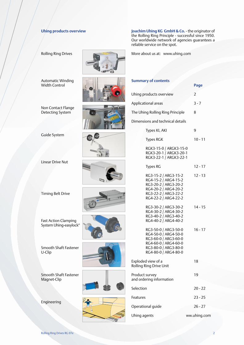
Uhing products overview
Rolling Ring Drives
Automatic Winding Width Control
Non Contact Flange Detecting System
Guide System
Linear Drive Nut
Timing Belt Drive
Fast Action Clamping System Uhing-easylock®
Smooth Shaft Fastener U-Clip
Smooth Shaft FastenerMagnet-Clip
Engineering
Joachim Uhing KG GmbH & Co. - the originator ofthe Rolling Ring Principle - successful since 1950.Our worldwide network of agencies guarantees areliable service on the spot.
More about us at: www.uhing.com
Summary of contentsPage
Uhing products overview 2
Applicational areas 3 - 7
The Uhing Rolling Ring Principle 8
Dimensions and technical details
Types KI, AKI 9
Types RGK 10 - 11
RGK3-15-0 / ARGK3-15-0RGK3-20-1 / ARGK3-20-1RGK3-22-1 / ARGK3-22-1
Types RG 12 - 17
RG3-15-2 / ARG3-15-2 12 - 13RG4-15-2 / ARG4-15-2RG3-20-2 / ARG3-20-2RG4-20-2 / ARG4-20-2RG3-22-2 / ARG3-22-2RG4-22-2 / ARG4-22-2
RG3-30-2 / ARG3-30-2 14 - 15RG4-30-2 / ARG4-30-2RG3-40-2 / ARG3-40-2RG4-40-2 / ARG4-40-2
RG3-50-0 / ARG3-50-0 16 - 17RG4-50-0 / ARG4-50-0RG3-60-0 / ARG3-60-0RG4-60-0 / ARG4-60-0RG3-80-0 / ARG3-80-0RG4-80-0 / ARG4-80-0
Exploded view of a 18Rolling Ring Drive Unit
Product survey 19and ordering information
Selection 20 - 22
Features 23 - 25
Operational guide 26 - 27
Uhing agents ww.uhing.com
3 Rolling Ring Drives RG 07e
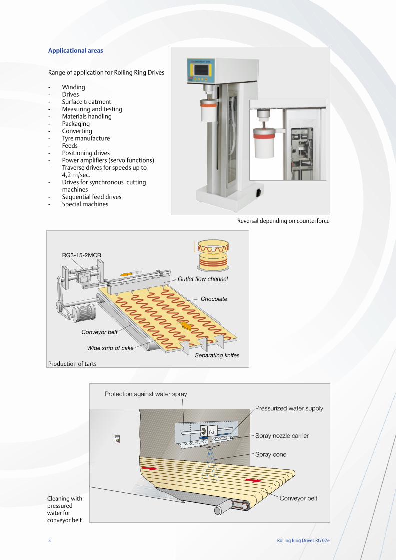
Applicational areas
Range of application for Rolling Ring Drives
- Winding- Drives- Surface treatment- Measuring and testing- Materials handling- Packaging- Converting- Tyre manufacture- Feeds- Positioning drives- Power amplifiers (servo functions)- Traverse drives for speeds up to
4,2 m/sec.- Drives for synchronous cutting
machines- Sequential feed drives- Special machines
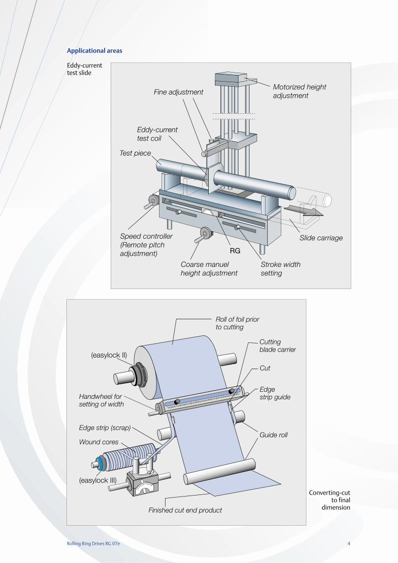
Pressurized water supply
Spray cone
Conveyor belt
Protection against water spray
Spray nozzle carrier
Cleaning with pressuredwater for conveyor belt
Production of tarts
Reversal depending on counterforce
Rolling Ring Drives RG 07e 4
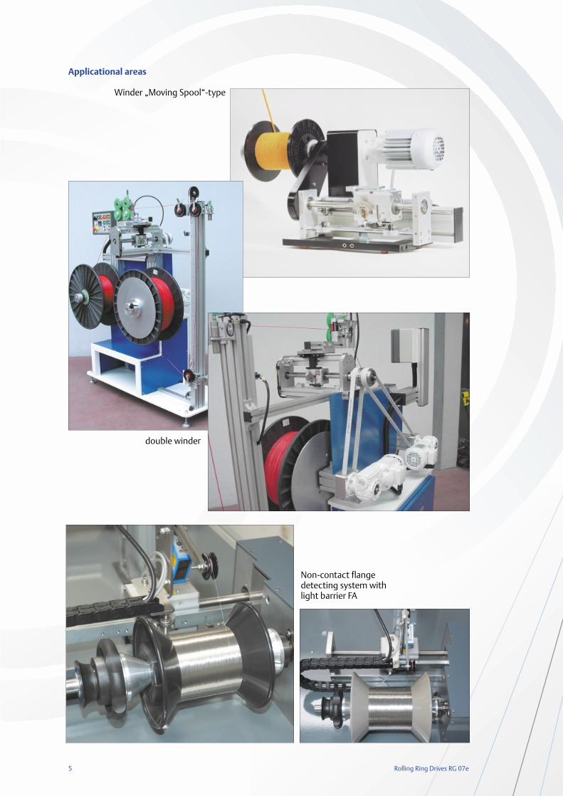
Applicational areas
Eddy-current test slide
Converting-cut to final
dimension
12
3 4 5 6 7 89
10
Fine adjustment
Eddy-currenttest coil
Test piece
Speed controller(Remote pitchadjustment)
Coarse manuelheight adjustment
RG
Stroke width setting
Slide carriage
Motorized height adjustment
12
3 4 5 6 7 8 9 10
(easylock II)
Handwheel forsetting of width
Edge strip (scrap)
Wound cores
(easylock III)
Finished cut end product
Guide roll
Cutting blade carrier
Cut
Edge strip guide
Roll of foil priorto cutting
5 Rolling Ring Drives RG 07e
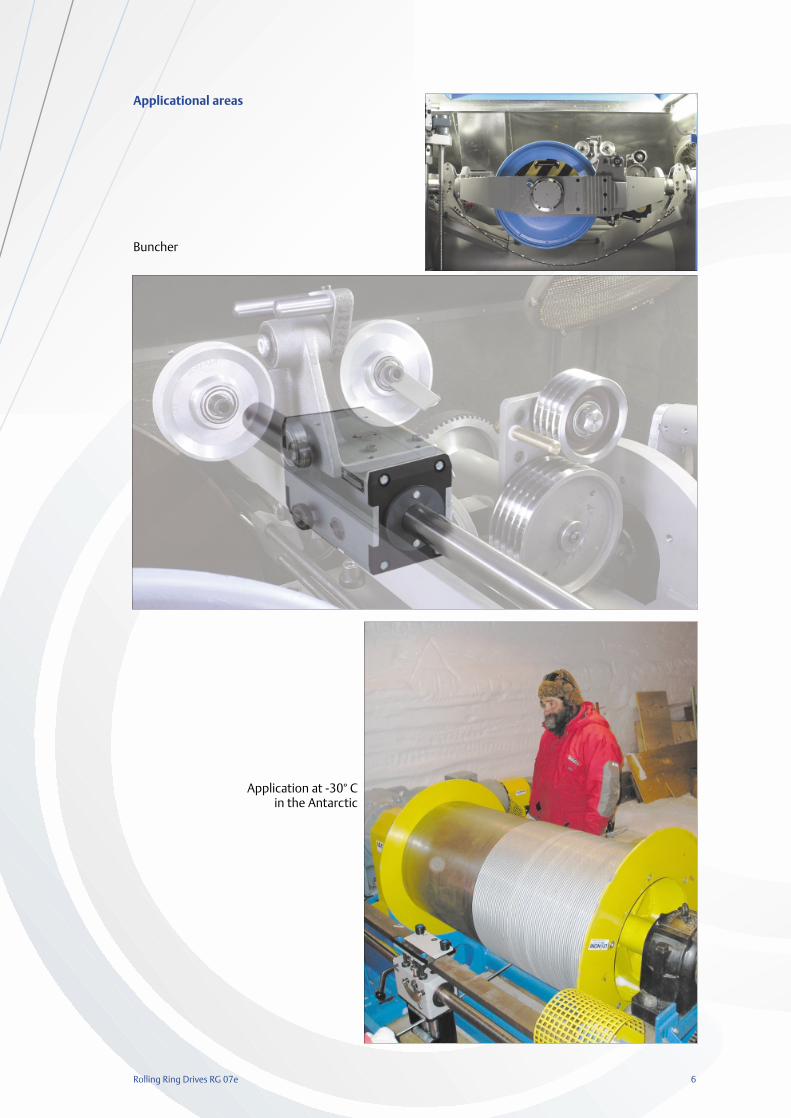
Applicational areas
Winder „Moving Spool“-type
double winder
Non-contact flangedetecting system withlight barrier FA
Rolling Ring Drives RG 07e 6
Applicational areas
Buncher
Application at -30° C in the Antarctic
7 Rolling Ring Drives RG 07e
Coa
ting
Feed
ing
Man
ipul
atin
g
Mea
surin
g/te
stin
g
Ope
ning
/clo
sing
Posi
tion
ing
Cle
anin
g
Cut
ting
/par
ting
Spra
ying
Sequ
enci
ng
Link
ing
Pack
ing
Spre
adin
g
Win
ding
Mix
ing
Function
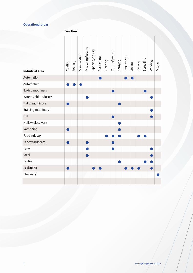
Operational areas
Industrial Area
Automation
Automobile
Baking machinery
Wire + Cable industry
Flat glass/mirrors
Braiding machinery
Foil
Hollow glass ware
Varnishing
Food industry
Paper/cardboard
Tyres
Steel
Textile
Packaging
Pharmacy
Rolling Ring Drives RG 07e 8
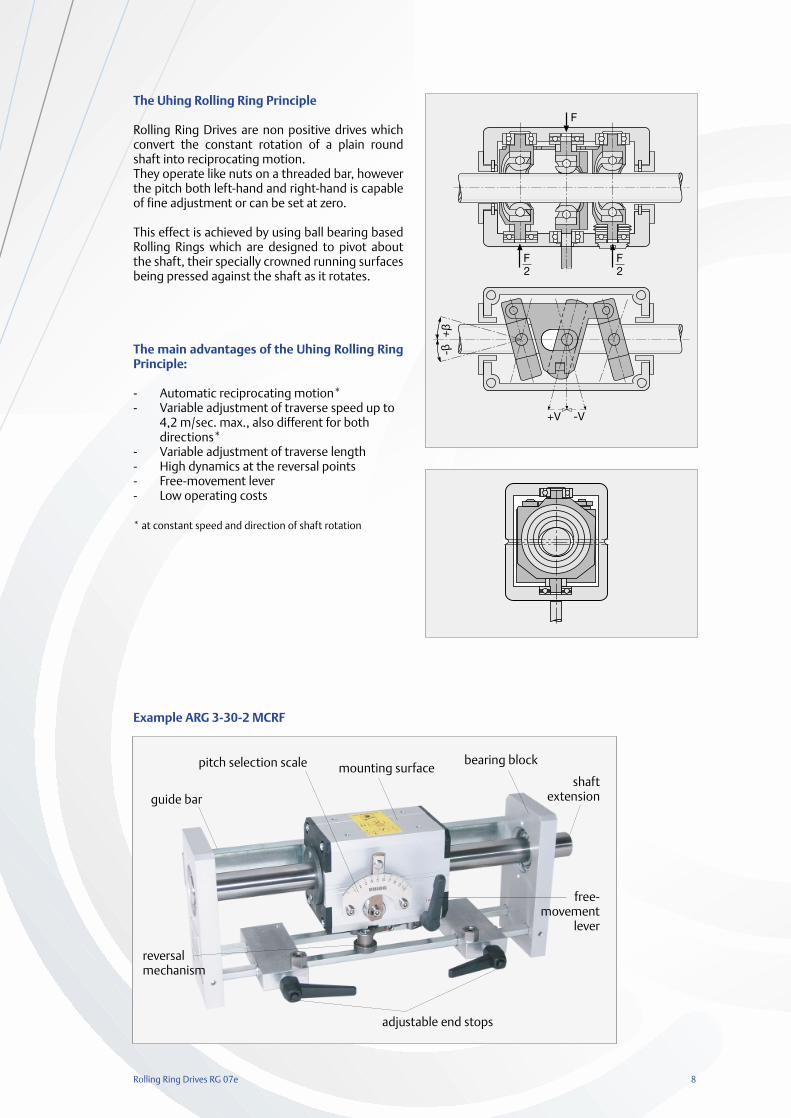
The Uhing Rolling Ring Principle
Rolling Ring Drives are non positive drives whichconvert the constant rotation of a plain roundshaft into reciprocating motion.They operate like nuts on a threaded bar, howeverthe pitch both left-hand and right-hand is capableof fine adjustment or can be set at zero.
This effect is achieved by using ball bearing basedRolling Rings which are designed to pivot aboutthe shaft, their specially crowned running surfacesbeing pressed against the shaft as it rotates.
The main advantages of the Uhing Rolling RingPrinciple:
- Automatic reciprocating motion*- Variable adjustment of traverse speed up to
4,2 m/sec. max., also different for both directions*
- Variable adjustment of traverse length- High dynamics at the reversal points- Free-movement lever- Low operating costs
* at constant speed and direction of shaft rotation
F
F2
F2
+V -V
+β
-β
Example ARG 3-30-2 MCRF
pitch selection scale mounting surface
guide bar
bearing block
shaftextension
free-movement
lever
reversal mechanism
adjustable end stops
9 Rolling Ring Drives RG 07e
The CAD - drawingfiles are available at
www.uhing.com
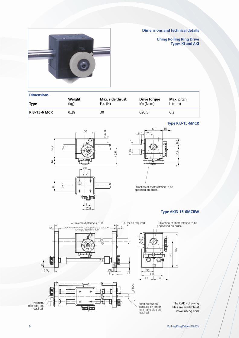
DimensionsWeight Max. side thrust Drive torque Max. pitch
Type (kg) FRG (N) M0 (Ncm) h (mm)
KI3-15-6 MCR 0,28 30 6±0,5 6,2
Dimensions and technical details
Uhing Rolling Ring DriveTypes KI and AKI
Type KI3-15-6MCR
Type AKI3-15-6MCRW
1 23
4567
89
10
1 2
34
567
89
10
Rolling Ring Drives RG 07e 10
Øg
a
bc
d
e
f
Ør
Øs
Ød h
6
h i l
7 k
tmax
Ø20
g
o
nm
p
adjustable
free movementlever
Direction ofshaft rotationas required
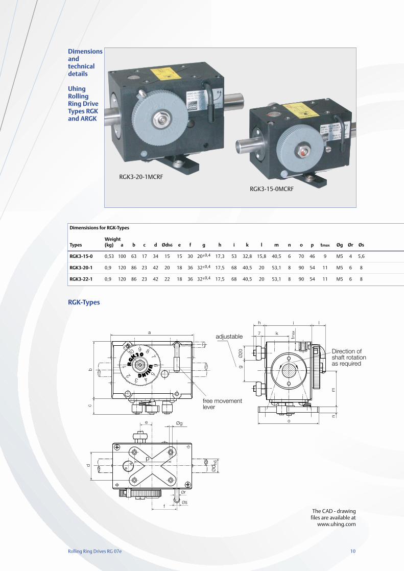
RGK-Types
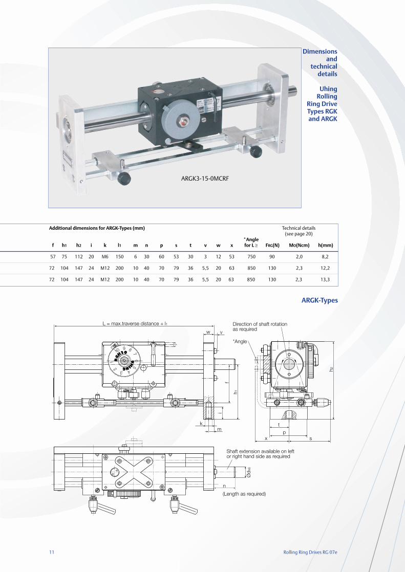
Dimensionsand technicaldetails
Uhing RollingRing DriveTypes RGKand ARGK
RGK3-20-1MCRF
RGK3-15-0MCRF
The CAD - drawingfiles are available at
www.uhing.com
Dimensisions for RGK-Types
WeightTypes (kg) a b c d Ødh6 e f g h i k l m n o p tmax Øg Ør Øs
RGK3-15-0 0,53 100 63 17 34 15 15 30 20±0,4 17,3 53 32,8 15,8 40,5 6 70 46 9 M5 4 5,6
RGK3-20-1 0,9 120 86 23 42 20 18 36 32±0,4 17,5 68 40,5 20 53,1 8 90 54 11 M5 6 8
RGK3-22-1 0,9 120 86 23 42 22 18 36 32±0,4 17,5 68 40,5 20 53,1 8 90 54 11 M5 6 8
11 Rolling Ring Drives RG 07e
L = max.traverse distance + l1
fi
w v
km
h1
n
Ødh
6
(Length as required)
Shaft extension available on leftor right hand side as required
px s
h2Direction of shaft rotationas required
*Angle
t
Additional dimensions for ARGK-Types (mm) Technical details(see page 20)
*Anglef h1 h2 i k l1 m n p s t v w x for L ≥ FRG(N) MO(Ncm) h(mm)
57 75 112 20 M6 150 6 30 60 53 30 3 12 53 750 90 2,0 8,2
72 104 147 24 M12 200 10 40 70 79 36 5,5 20 63 850 130 2,3 12,2
72 104 147 24 M12 200 10 40 70 79 36 5,5 20 63 850 130 2,3 13,3
Dimensionsand
technicaldetails
Uhing Rolling
Ring DriveTypes RGKand ARGK
ARGK-Types
ARGK3-15-0MCRF
Rolling Ring Drives RG 07e 12
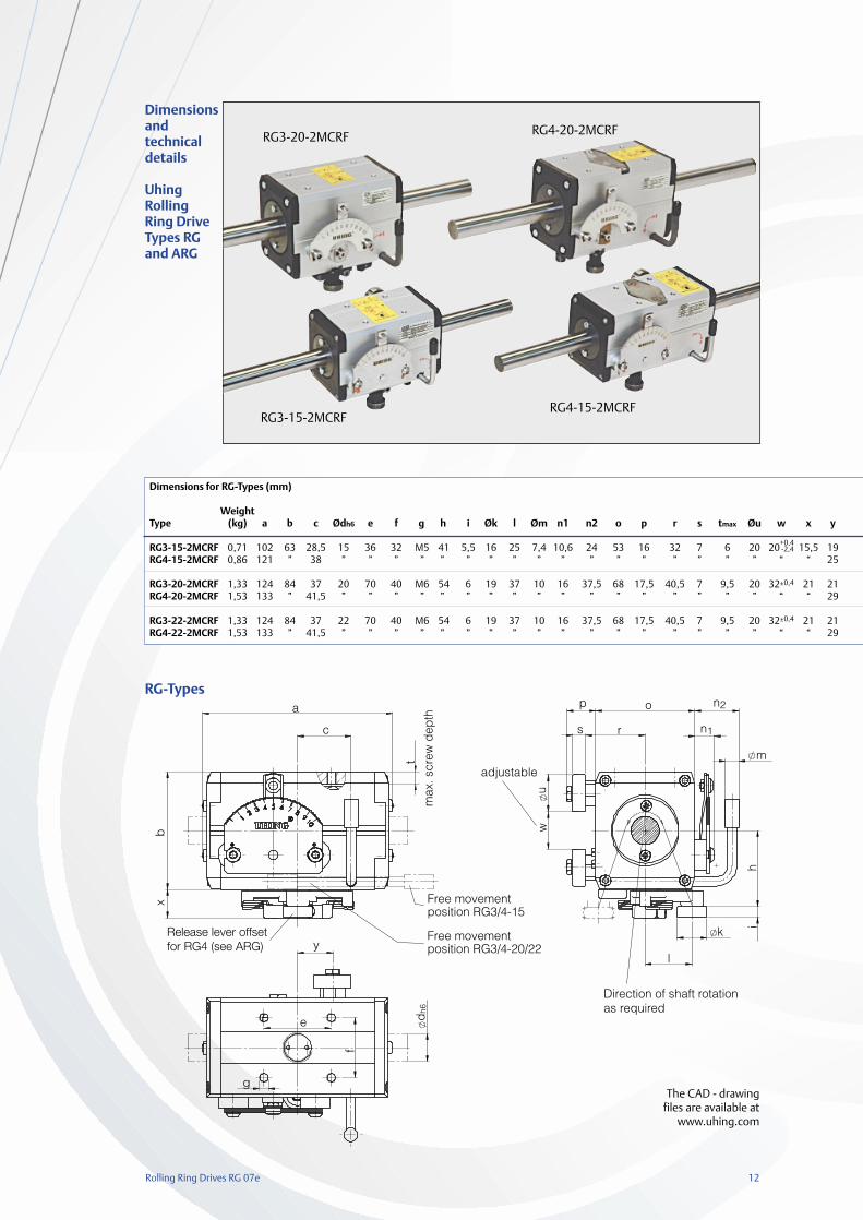
Dimensions for RG-Types (mm)
WeightType (kg) a b c Ødh6 e f g h i Øk l Øm n1 n2 o p r s tmax Øu w x y
RG3-15-2MCRF 0,71 102 63 28,5 15 36 32 M5 41 5,5 16 25 7,4 10,6 24 53 16 32 7 6 20 20+0,4 15,5 19RG4-15-2MCRF 0,86 121 ” 38 ” ” ” ” ” ” ” ” ” ” ” ” ” ” ” ” ” “ “ 25
RG3-20-2MCRF 1,33 124 84 37 20 70 40 M6 54 6 19 37 10 16 37,5 68 17,5 40,5 7 9,5 20 32±0,4 21 21RG4-20-2MCRF 1,53 133 ” 41,5 ” ” ” ” ” ” ” ” ” ” ” ” ” ” ” ” ” “ “ 29
RG3-22-2MCRF 1,33 124 84 37 22 70 40 M6 54 6 19 37 10 16 37,5 68 17,5 40,5 7 9,5 20 32±0,4 21 21RG4-22-2MCRF 1,53 133 ” 41,5 ” ” ” ” ” ” ” ” ” ” ” ” ” ” ” ” ” “ “ 29
m
k
ih
n1
n2o
rs
p
uw
a
c
td
h6
y
e
g
f
l
xb
Direction of shaft rotation as required
Free movement position RG3/4-15
Free movement position RG3/4-20/22
max
. scr
ew d
epth
adjustable
Release lever offsetfor RG4 (see ARG)
RG-Types
Dimensionsand technicaldetails
Uhing RollingRing DriveTypes RGand ARG
The CAD - drawingfiles are available at
www.uhing.com
RG4-20-2MCRF
RG4-15-2MCRF
RG3-20-2MCRF
RG3-15-2MCRF
-2,4
13 Rolling Ring Drives RG 07e
Release lever offsetfor RG4 types
w
v
mk
i
h 1
n
dh6
h 2
s
pt
x
y
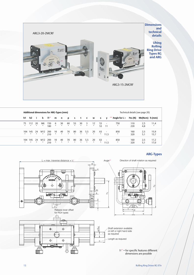
L = max. traverse distance + l1* Direction of shaft rotation as requiredAngle**
Shaft extension availableon left or right hand sideas required
Length as reqiured
Additional dimensions for ARG-Types (mm) Technical details (see page 20)
h1 h2 i k l1* m n p s t v w x y ** Angle for L ≥ FRG (N) M0(Ncm) h (mm)
75 112 20 M6 150 6 30 60 53 30 3 12 53 - 750 110 2,5 11,4” ” ” ” 180 ” ” ” ” ” ” ” 53 11 “ 220 4,8 “
104 145 24 M12 200 10 40 70 80 36 5,5 20 63 - 850 160 2,5 15,9” ” ” ” 210 ” ” ” ” ” ” ” ” 11,5 ” 320 5,1 15,7
104 145 24 M12 200 10 40 70 80 36 5,5 20 63 - 850 160 2,5 17,2” ” ” ” 210 ” ” ” ” ” ” ” ” 11,5 ” 320 5,1 17,0
Dimensionsand
technicaldetails
Uhing Rolling
Ring DriveTypes RGand ARG
ARG-Types
l1* = for specific features different dimensions are possible
ARG3-15-2MCRF
ARG3-20-2MCRF
Rolling Ring Drives RG 07e 14
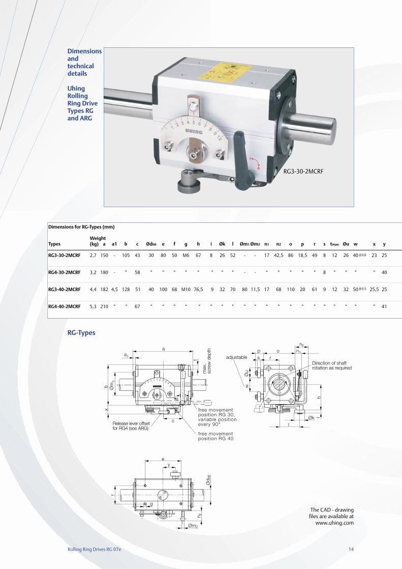
Dimensions for RG-Types (mm)
WeightTypes (kg) a a1 b c Ødh6 e f g h i Øk l Øm1 Øm2 n1 n2 o p r
RG3-30-2MCRF 2,7 150 - 105 43 30 80 50 M6 67 8 26 52 - - 17 42,5 86 18,5 49
RG4-30-2MCRF 3,2 180 - ” 58 ” ” ” ” ” ” ” ” - - “ ” ” ” ”
RG3-40-2MCRF 4,4 182 4,5 128 51 40 100 68 M10 76,5 9 32 70 80 11,5 17 68 110 20 61
RG4-40-2MCRF 5,3 210 ” ” 67 ” ” ” ” ” ” ” ” ” ” ” ” ” ” ”
s tmax Øu w x y
8 12 26 40 23 25
8 ” ” ” ” 40
9 12 32 50 25,5 25
” ” ” ” ” 41
free movementposition RG 30,variable positionevery 90°
free movementposition RG 40
adjustable
1 1
i
RG-Types
Dimensionsand technicaldetails
Uhing RollingRing DriveTypes RGand ARG
The CAD - drawingfiles are available at
www.uhing.com
RG3-30-2MCRF
±0,6
±0,5
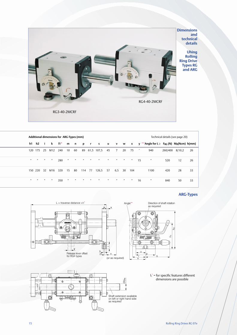
15 Rolling Ring Drives RG 07e
*
Additional dimensions for ARG-Types (mm) Technical details (see page 20)
h1 h2 i k l1* m n p r s u v w x y **Angle for L ≥ FRG (N) M0(Ncm) h(mm)
120 175 25 M12 240 10 60 89 61,5 107,5 45 7 20 75 ˜ 940 260/400 8/10,2 26
” ” ” ” 280 ” ” ” ” ” ” ” ” ” 15 ” 520 12 26
150 220 32 M16 320 15 80 114 77 126,5 57 6,5 30 104 1100 420 28 33
” ” ” ” 350 ” ” ” ” ” ” ” ” ” 16 ” 840 50 33
Dimensionsand
technicaldetails
Uhing Rolling
Ring DriveTypes RGand ARG
ARG-Types
RG3-40-2MCRF
RG4-40-2MCRF
l1* = for specific features different
dimensions are possible
Rolling Ring Drives RG 07e 16
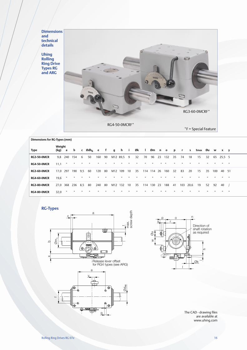
Dimensions for RG-Types (mm)
WeightType (kg) a b c Ødh6 e f g h i Øk l Øm n o p r s tmax Øu w x y
RG3-50-0MCR 9,8 240 154 6 50 160 90 M12 89,5 9 32 70 96 23 132 35 74 18 15 32 65 25,5 5
RG4-50-0MCR 11,1 ” ” ” ” ” ” ” ” ” ” ” ” ” ” ” ” ” ” ” ” ” ”
RG3-60-0MCR 17,0 297 190 9,5 60 120 80 M12 109 10 35 114 114 26 160 32 83 20 15 35 100 40 51
RG4-60-0MCR 19,6 ” ” ” ” ” ” ” ” ” ” ” ” ” ” ” ” ” ” ” ” ” ”
RG3-80-0MCR 27,0 368 236 8,5 80 240 80 M12 132 10 35 114 130 23 188 41 103 20,6 19 52 92 40 /
RG4-80-0MCR 32,0 ” ” ” ” ” ” ” ” ” ” ” ” ” ” ” ” ” ” ” ” ” ”
Direction ofshaft rotationas required
i
4
Release lever offsetfor RG4 types (see ARG)
max
.sc
rew
dep
th
RG-Types
Dimensionsand technicaldetails
Uhing RollingRing DriveTypes RGand ARG
The CAD - drawing filesare available at
www.uhing.com
RG4-50-0MCRF*
RG3-60-0MCRF*
*F = Special Feature
17 Rolling Ring Drives RG 07e
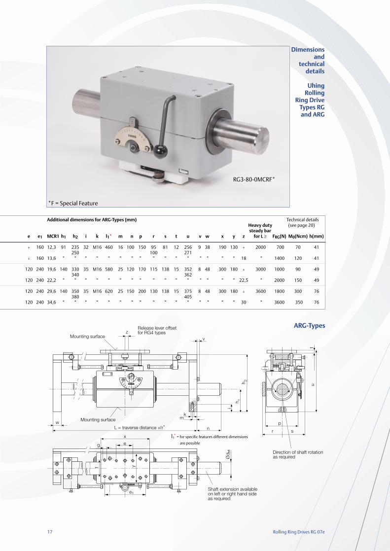
4
f y
*
e1
eg
Additional dimensions for ARG-Types (mm) Technical detailsHeavy duty (see page 20)steady bar
MCR1 h1 h2 i k l1* m n p r s t u v w x y z for L ≥ FRG(N) M0(Ncm) h(mm)
12,3 91 235 32 M16 460 16 100 150 95 81 12 256 9 38 190 130 ÷ 2000 700 70 41 250 100 271
13,6 ” ” ” ” ” ” ” ” ” ” ” ” ” ” ” ” 18 ” 1400 120 41
19,6 140 330 35 M16 580 25 120 170 115 138 15 352 8 48 300 180 ÷ 3000 1000 90 49340 362
22,2 ” ” ” ” ” ” ” ” ” ” ” ” ” ” ” ” 22,5 ” 2000 150 49
29,6 140 350 35 M16 620 25 150 200 130 138 15 375 8 48 300 180 ÷ 3600 1800 300 76380 405
34,6 ” ” ” ” ” ” ” ” ” ” ” ” ” ” ” ” 30 ” 3600 350 76
Dimensionsand
technicaldetails
Uhing Rolling
Ring DriveTypes RGand ARG
ARG-Types
RG3-80-0MCRF*
*F = Special Feature
l1* = for specific features different dimensions
are possible
e e1
÷ 160
÷ 160
120 240
120 240
120 240
120 240
Rolling Ring Drives RG 07e 18
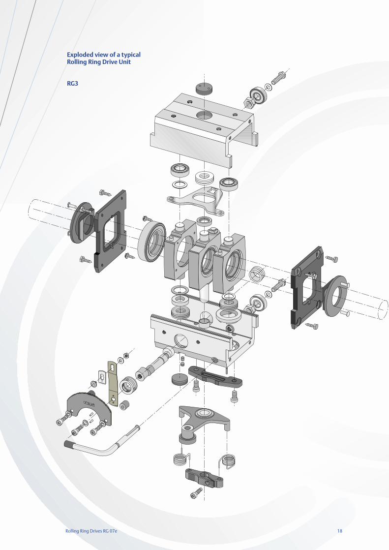
Exploded view of a typicalRolling Ring Drive Unit
RG3
19 Rolling Ring Drives RG 07e
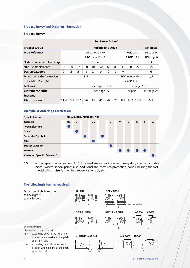
Product Survey and Ordering Information
Product Survey
Example of Ordering Specification
* X e.g. Adapter (twist-free coupling), intermediate support bracket, heavy duty steady bar, drive motor, wipers, special paint finish, additional anti-corrosion protection, double bearing support, special pitch, noise dampening, sequence control, etc.
The following is further required:
Direction of shaft rotationto the right = Rto the left = L
Shaft extension,diameter and length (mm)ra = extending beyond the righthand
bracket when looking at the pitch selection scale
la = extending beyond the lefthand bracket when looking at the pitch selection scale
Uhing Linear Drives®
Product Group Rolling Ring Drive Kinemax
Type Reference RG page 12 - 16 RGK p.10 KI page 9
ARG page 13 -17 ARGK p.11 AKI page 9
Style Number of rolling rings 3 or 4 3 3
Size Shaft diameter 15 20 22 30 40 50 60 80 15 20 22 15
Design Category 2 2 2 2 2 0 0 0 0 1 1 6
Direction of shaft rotation L, R RGK independent L, R
L = left R = right ARGK L, R
Features see page 23 - 25 s. page 23-25
Customer Specific see page 25 wipers see page 25
Features
Pitch max. (mm) 11,4 15,9 17,2 26 33 41 49 76 8,5 12,2 13,3 6,2
Type Reference KI, AKI, RGK, ARGK, RG, ARG,
Example RG 3 - 30 - 2 M C R F X
Type Reference
Style
Seperator Symbol
Size
Design Category
Features
Customer Specific Features *
Rolling Ring Drives RG 07e 20
Selection
1. Formulae and related units
a(m/sec2) = acceleration at the reversal pointd(mm) = shaft diameterF(N) = side thrust requiredFRG(N) = side thrust produced by Rolling Ring
Drive UnitFR(N) = friction (FN ·µ) only relevant when the
the associated mass is mounted on its own independent carriage
FN(N) = normal force of total weight of asso-ciated mass and carriage
µ = coefficent of frictionFZ(N) = additional force e.g. component of
the cutting force of a separatorf(mm) = shaft sag from Fig.1g(m/sec2) = acceleration due to gravity
(9,81m/sec2)h(mm) = pitch of unit (travel per shaft
revolution)hmax(mm) = maximum pitch see Fig.3l(mm) = length of shaft between centres of
bearing bracketsm(kg) = total mass to be moved, including
the Rolling Ring Drive Unit, connections etc.
Md (Ncm) = drive torqueMo (Ncm) = idling torque n(r.p.m.) = shaft speedncrit(r.p.m.)= critical shaft speedP(kW) = drive power requireds(mm) = length of reversal slowdown camt(sec) = reversal time from Fig.2v(m/sec) = max. traverse speed required. Should
always be calculated at maximumunit pitch (pitch setting 10 from Fig.2)
C(N) = dynamic loading of Rolling RingsPR(N) = radial loading of Rolling Rings
2. PreselectionA unit should be preselected by estimating the sidethrust required and/or giving consideration to thepermissible shaft sag f with reference to Fig. 1.
2.1. Rolling Ring Drive Units with Instantaneous Reversal (Feature M)
Suitable for traversing speeds up to:RG15, RG20: 0,30 m/secKinemax, RG30, RG40: 0,60 m/secRG50, RG60, RG80: 0,25 m/sec
The reversal time t is dependent on the size of theRolling Ring Unit and the pitch selected via the scale(pitch angle). The reversal action is of the triggeredthrowover type.
F = 2.5 m · v + FR + FZ + 1.25 · m · g +(Fk)*t
*see section 6 - Winding Applications
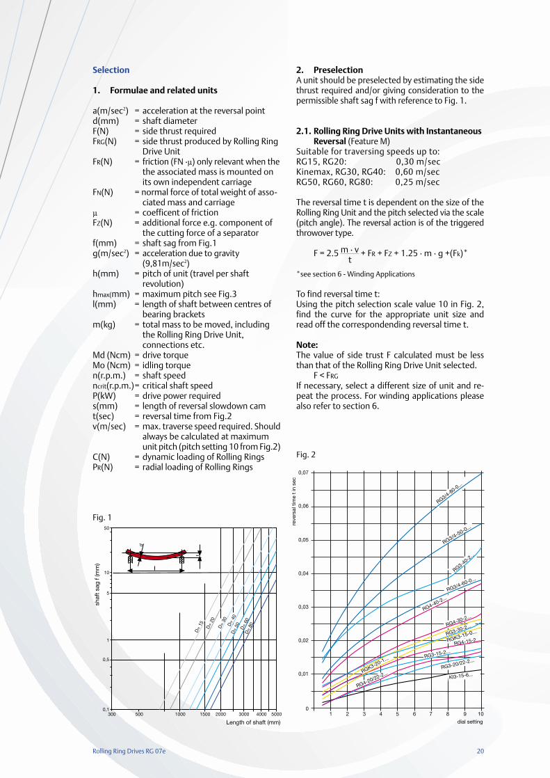
To find reversal time t:Using the pitch selection scale value 10 in Fig. 2,find the curve for the appropriate unit size andread off the correspondending reversal time t.
Note: The value of side trust F calculated must be lessthan that of the Rolling Ring Drive Unit selected.
F < FRG
If necessary, select a different size of unit and re-peat the process. For winding applications pleasealso refer to section 6.
d
f
01 2 3 4 5 6 7 8 9 10
0,01
0,02
0,03
0,04
0,05
0,06
0,07
RG3/4-80-0...
RG4-30-2...
KI3-15-6...RG3-20/22-2...
RG4-20/22-2...
RG3-15-2...
RG3-30-2...
RGK3-15-0...
RGK3-20-1...
dial setting
reve
rsal
tim
e t
in s
ec
RG4-15-2...
RG3-40-2
...
RG3/4-50-0...
RG3/4-60-0...
RG4-40-2...
Fig. 2
Fig. 1
21 Rolling Ring Drives RG 07e
2.2 Rolling Ring Drive Units with reversal slowdown (Feature V)
Suitable for traverse speeds up to approx. 4,2 m/sec.A reversal with slowdown reduces the forces impo-sed on the unit at the reversal point.
F = 1.25 · m · a + FR + FZ + 1.25 · m · g
If a maximum rate of acceleration a is specified,the required length s for the delay cam is calcula-ted as follows:
s =v2 · 103
a
If the delay cam length s is specified, the accelera-tion a is calculated as follows:
a =v2 · 103
s
3. Side thrustThe value of side thrust F calculated must be lessthan that of the Rolling Ring Drive Unit selected.
F < FRG
If the side thrust available from the unit chosen istoo little, either a larger unit or a longer length ofdelay must be selected.
The thrust provided by the units is virtually con-stant for shaft speeds above 300 rpm. For slowerspeeds the thrust increases a little over the speci-fied catalogue values as the speed reducestowards zero.For increase of lifetime there should only be adjus-ted the side thrust which is needed as a result ofcalculation according to 2.1 and 2.2.
4. Shaft Speed
4.1. Calculation
n = v · 6 · 104
hmax
The speed so calculated must not be exceeded.Recommended speed range:
nmin = 5 rpmnmax = 3000 rpm
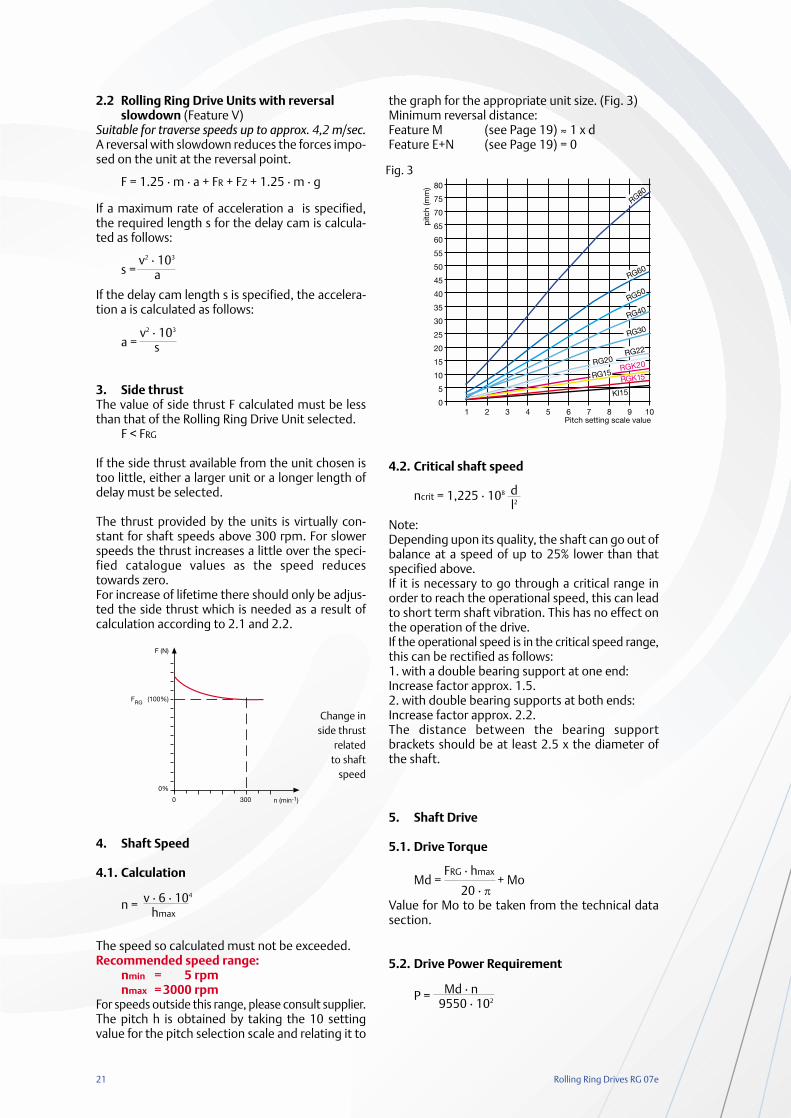
For speeds outside this range, please consult supplier.The pitch h is obtained by taking the 10 settingvalue for the pitch selection scale and relating it to
the graph for the appropriate unit size. (Fig. 3)Minimum reversal distance:Feature M (see Page 19) ≈ 1 x dFeature E+N (see Page 19) = 0
4.2. Critical shaft speed
ncrit = 1,225 · 108 d l2
Note:Depending upon its quality, the shaft can go out ofbalance at a speed of up to 25% lower than thatspecified above.If it is necessary to go through a critical range inorder to reach the operational speed, this can leadto short term shaft vibration. This has no effect onthe operation of the drive.If the operational speed is in the critical speed range,this can be rectified as follows:1. with a double bearing support at one end:Increase factor approx. 1.5.2. with double bearing supports at both ends:Increase factor approx. 2.2.The distance between the bearing supportbrackets should be at least 2.5 x the diameter ofthe shaft.
5. Shaft Drive
5.1. Drive Torque
Md =FRG · hmax
+ Mo20 · π
Value for Mo to be taken from the technical datasection.
5.2. Drive Power Requirement
P = Md · n 9550 · 102
F (N)
FRG (100%)
0%
0 300 n (min-1)
Fig. 3
Change inside thrust
related to shaft
speed
Rolling Ring Drives RG 07e 22
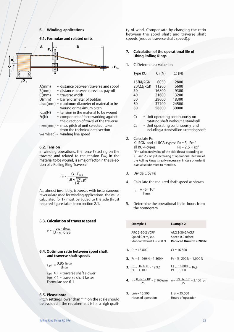
6. Winding applications
6.1. Formulae and related units
A(mm) = distance between traverse and spoolB(mm) = distance between previous pay-offC(mm) = traverse widthD(mm) = barrel diameter of bobbindmax(mm) = maximum diameter of material to be
wound or maximum pitchFZug(N) = tension in the material to be woundFK(N) = component of force working against
the direction of travel of the traversehmax(mm) = max. pitch of unit selected, taken
from the technical data sectionvw(m/sec) = winding line speed
6.2. TensionIn winding operations, the force FK acting on thetraverse and related to the tension FZug in thematerial to be wound, is a major factor in the selec-tion of a Rolling Ring Traverse.
As, almost invariably, traverses with instantaneousreversal are used for winding applications, the valuecalculated for FK must be added to the side thrustrequired figure taken from section 2.1.
6.3. Calculation of traverse speed
v = vw · dmax D · π · 0,95
6.4. Optimum ratio between spool shaft and traverse shaft speeds
iopt = 0,95 hmaxdmax
iopt > 1 = traverse shaft sloweriopt < 1 = traverse shaft fasterFormulae see 6.1.
6.5. Please notePitch settings lower than ”1” on the scale shouldbe avoided if the requirement is for a high quali-
ty of wind. Compensate by changing the ratiobetween the spool shaft and traverse shaftspeeds (reduce traverse shaft speed).p
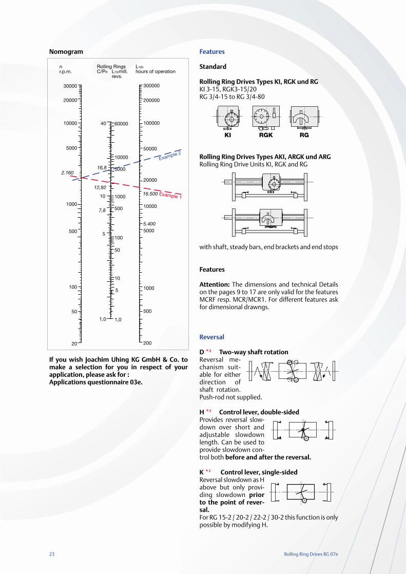
7. Calculation of the operational life of Uhing Rolling Rings
1. C Determine a value for:
Type RG C1 (N) C2 (N)
15/KI/RGK 6050 280020/22/RGK 11200 560030 16800 930040 21600 1320050 29600 1830060 37700 2450080 58800 39000
C1 = Unit operating continuously on rotating shaft without a standstill
C2 = Unit operating continuously and including a standstill on a rotating shaft
2. Calculate PR
Kl, RGK and all RG3-types: PR = 5 · FRG*all RG 4-types: PR = 2.5 · FRG**F = calculated value of the side thrust according to2.1 and 2.2 only if increasing of operational life time of the Rolling Rings is really necessary. In case of order it is an absolute must to mention.
3. Divide C by PR
4. Calculate the required shaft speed as shown
n = v · 6 · 104
hmax
5. Determine the operational life in hours fromthe nomogram.
Example 1
ARG 3-30-2 VCRFSpeed 0,9 m/sec.Standard thrust F = 260 N
C1 = 16.800
PR = 5 · 260 N = 1.300 N
C1 = 16.800 = 12.92PR 1.300
n = 0,9 · 6 · 104
= 2.160 rpm25
L10h = 16.500Hours of operation
Example 2
ARG 3-30-2 VCRFSpeed 0,9 m/sec.Reduced thrust F = 200 N
C1 = 16.800
PR = 5 · 200 N = 1.000 N
C1 = 16.800 = 16,8PR 1.000
n = 0,9 · 6 · 104
= 2.160 rpm 25
L10h = 35.000Hours of operation
1.
2.
3.
4.
5.
C
A B
FZug
D
d
FK
23 Rolling Ring Drives RG 07e
Nomogram
If you wish Joachim Uhing KG GmbH & Co. tomake a selection for you in respect of yourapplication, please ask for :Applications questionnaire 03e.
Features
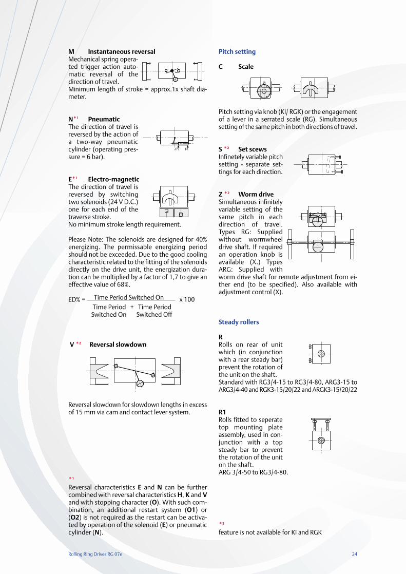
Standard
Rolling Ring Drives Types KI, RGK und RGKI 3-15, RGK3-15/20RG 3/4-15 to RG 3/4-80
Rolling Ring Drives Types AKI, ARGK und ARGRolling Ring Drive Units KI, RGK and RG
with shaft, steady bars, end brackets and end stops
Features
Attention: The dimensions and technical Detailson the pages 9 to 17 are only valid for the featuresMCRF resp. MCR/MCR1. For different features askfor dimensional drawngs.
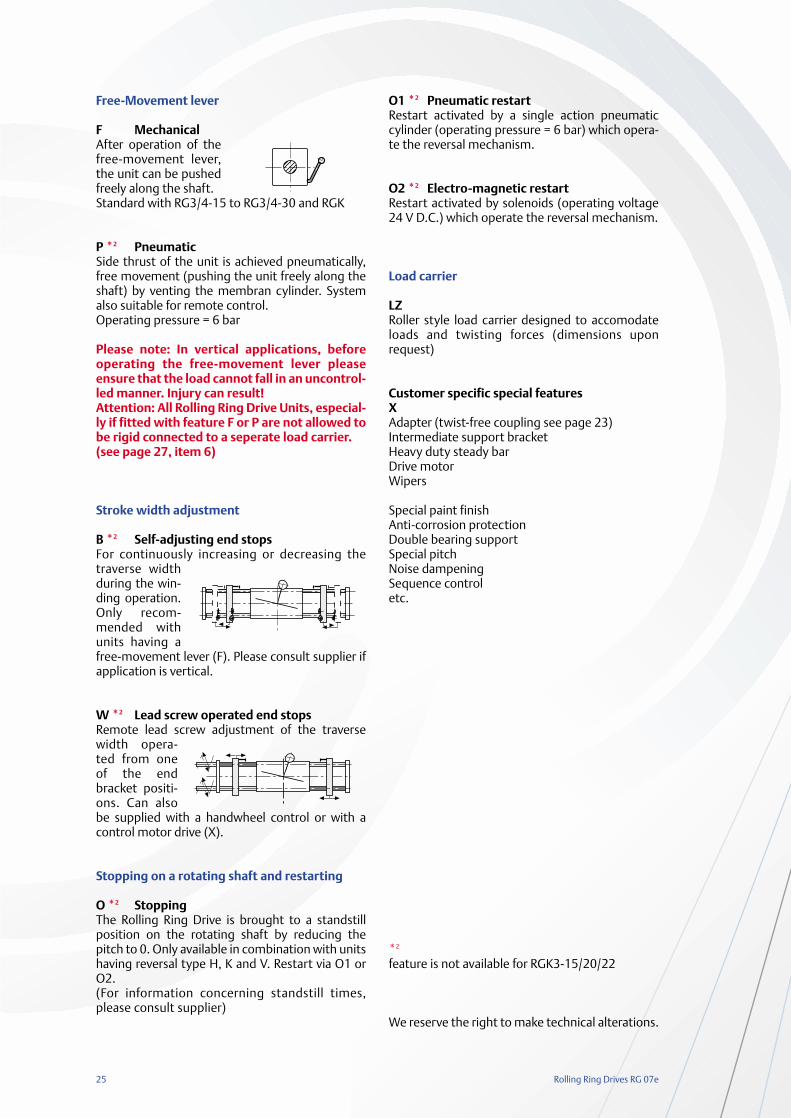
Reversal
D *2 Two-way shaft rotationReversal me-chanism suit-able for eitherdirection ofshaft rotation.Push-rod not supplied.
H *2 Control lever, double-sidedProvides reversal slow-down over short andadjustable slowdownlength. Can be used toprovide slowdown con-trol both before and after the reversal.
K *2 Control lever, single-sidedReversal slowdown as Habove but only provi-ding slowdown priorto the point of rever-sal.For RG 15-2 / 20-2 / 22-2 / 30-2 this function is onlypossible by modifying H.
V
Rolling Ring Drives RG 07e 24
M Instantaneous reversalMechanical spring opera-ted trigger action auto-matic reversal of thedirection of travel.Minimum length of stroke = approx.1x shaft dia-meter.
N*1 PneumaticThe direction of travel isreversed by the action ofa two-way pneumaticcylinder (operating pres-sure = 6 bar).
E*1 Electro-magneticThe direction of travel isreversed by switchingtwo solenoids (24 V D.C.)one for each end of thetraverse stroke.No minimum stroke length requirement.
Please Note: The solenoids are designed for 40%energizing. The permissable energizing periodshould not be exceeded. Due to the good coolingcharacteristic related to the fitting of the solenoidsdirectly on the drive unit, the energization dura-tion can be multiplied by a factor of 1,7 to give aneffective value of 68%.
ED% = Time Period Switched On x 100Time Period + Time Period
Switched On Switched Off
V *2 Reversal slowdown
Reversal slowdown for slowdown lengths in excessof 15 mm via cam and contact lever system.
*1
Reversal characteristics E and N can be furthercombined with reversal characteristics H, K and Vand with stopping character (O). With such com-bination, an additional restart system (O1) or(O2) is not required as the restart can be activa-ted by operation of the solenoid (E) or pneumaticcylinder (N).
Pitch setting
C Scale
Pitch setting via knob (KI/ RGK) or the engagementof a lever in a serrated scale (RG). Simultaneoussetting of the same pitch in both directions of travel.
S *2 Set scewsInfinetely variable pitchsetting - separate set-tings for each direction.
Z *2 Worm driveSimultaneous infinitelyvariable setting of thesame pitch in eachdirection of travel.Types RG: Suppliedwithout wormwheeldrive shaft. If requiredan operation knob isavailable (X.) TypesARG: Supplied withworm drive shaft for remote adjustment from ei-ther end (to be specified). Also available withadjustment control (X).
Steady rollers
RRolls on rear of unitwhich (in conjunctionwith a rear steady bar)prevent the rotation ofthe unit on the shaft.Standard with RG3/4-15 to RG3/4-80, ARG3-15 toARG3/4-40 and RGK3-15/20/22 and ARGK3-15/20/22
R1Rolls fitted to seperatetop mounting plateassembly, used in con-junction with a topsteady bar to preventthe rotation of the uniton the shaft.ARG 3/4-50 to RG3/4-80.
*2
feature is not available for KI and RGK
25 Rolling Ring Drives RG 07e
Free-Movement lever
F MechanicalAfter operation of thefree-movement lever,the unit can be pushedfreely along the shaft.Standard with RG3/4-15 to RG3/4-30 and RGK
P *2 PneumaticSide thrust of the unit is achieved pneumatically,free movement (pushing the unit freely along theshaft) by venting the membran cylinder. Systemalso suitable for remote control.Operating pressure = 6 bar
Please note: In vertical applications, beforeoperating the free-movement lever pleaseensure that the load cannot fall in an uncontrol-led manner. Injury can result!Attention: All Rolling Ring Drive Units, especial-ly if fitted with feature F or P are not allowed tobe rigid connected to a seperate load carrier. (see page 27, item 6)
Stroke width adjustment
B *2 Self-adjusting end stopsFor continuously increasing or decreasing thetraverse widthduring the win-ding operation.Only recom-mended withunits having afree-movement lever (F). Please consult supplier ifapplication is vertical.
W *2 Lead screw operated end stopsRemote lead screw adjustment of the traversewidth opera-ted from oneof the endbracket positi-ons. Can alsobe supplied with a handwheel control or with acontrol motor drive (X).
Stopping on a rotating shaft and restarting
O *2 StoppingThe Rolling Ring Drive is brought to a standstillposition on the rotating shaft by reducing thepitch to 0. Only available in combination with unitshaving reversal type H, K and V. Restart via O1 orO2.(For information concerning standstill times,please consult supplier)
O1 *2 Pneumatic restartRestart activated by a single action pneumaticcylinder (operating pressure = 6 bar) which opera-te the reversal mechanism.
O2 *2 Electro-magnetic restartRestart activated by solenoids (operating voltage24 V D.C.) which operate the reversal mechanism.
Load carrier
LZRoller style load carrier designed to accomodateloads and twisting forces (dimensions uponrequest)
Customer specific special featuresXAdapter (twist-free coupling see page 23)Intermediate support bracketHeavy duty steady barDrive motorWipers
Special paint finishAnti-corrosion protectionDouble bearing supportSpecial pitchNoise dampeningSequence controletc.
*2
feature is not available for RGK3-15/20/22
We reserve the right to make technical alterations.
Rolling Ring Drives RG 07e 26
Operational guide
Security advice: the movements of the traversedrive can evoke crushes. It has to be protectedagainst touches as well as the rotating shaft.
1. Shaft material1.1. Basic requirementsUhing Linear Drives should only be used in conjunc-tion with steel shafts manufactured from inductionsurface hardened, ground and finished bar of the fol-lowing quality, minimum:- surface hardness: 50 HRC- tolerance on diameter: h6- out of roundness: maximum one half of the
diameter variation permitted by ISO tolerance h6- true running tolerance (DIN ISO1101): ≤0.1 mm/m
1.2. Uhing precision shaftStandard: Material Cf 53, Mat.-Nr. 1.1213 inductionsurface hardened, 60-64 HRCRust resistant:Material X 40 Cr 13, Mat.-Nr. 1.4034 induction surfacehardened, 51-55 HRCRust and acid resistant:Material X 90 CrMoV 18 Mat.-Nr. 1.4112 inductionsurface hardened, 52-56 HRC- all ground and superfinished- surface roughness: mean value (DIN 4768 T.1)
Ra: ≤ 0.35 µm- tolerance on diameter: h6- out of roundness: maximum one half of the
diameter variation per mitted by ISO tolerance h6- true running tolerance (DIN ISO 1101):
≤ 0.1 mm/m
1.3. Uhing precision shafts with enhanced truerunning toleranceAvailable in the above styles, but - true running tole-rance (DIN ISO 1101): ≤ 0.03 mm/m
1.4. Leading end chamferThe leading end of the shaft should be chamfered toavoid damage to the Rolling Rings when screwing theunit onto the shaft.
The following method should befollowed to facilitate the screwingof the shaft into the unit:For units not having a pressurescrew (KI and types RG 4-15/20/22/30-2) the entry sidefor the shaft is not specified.
2. Shaft rotationThe mechanical reversal of theRolling Ring Drive is related tothe direction of shaft rotation. Itwill operate only when the rotati-on is as specified in the order(except for feature D and RGK-types).
When changing the direction of rotation, the pitchsymmetry must be checked and adjusted if necessary(see Operating Instructions 05e).
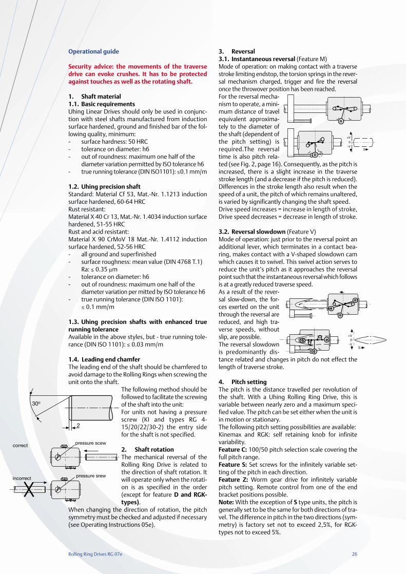
3. Reversal3.1. Instantaneous reversal (Feature M)Mode of operation: on making contact with a traversestroke limiting endstop, the torsion springs in the rever-sal mechanism charged, trigger and fire the reversalonce the throwover position has been reached.For the reversal mecha-nism to operate, a mini-mum distance of travelequivalent approxima-tely to the diameter ofthe shaft (dependent ofthe pitch setting) isrequired.The reversaltime is also pitch rela-ted (see Fig. 2, page 16). Consequently, as the pitch isincreased, there is a slight increase in the traversestroke length (and a decrease if the pitch is reduced).Differences in the stroke length also result when thespeed of a unit, the pitch of which remains unaltered,is varied by significantly changing the shaft speed.Drive speed increases = increase in length of stroke,Drive speed decreases = decrease in length of stroke.
3.2. Reversal slowdown (Feature V)Mode of operation: just prior to the reversal point anadditional lever, which terminates in a contact bea-ring, makes contact with a V-shaped slowdown camwhich causes it to swivel. This swivel action serves toreduce the unit’s pitch as it approaches the reversalpoint such that the instantaneous reversal which followsis at a greatly reduced traverse speed.As a result of the rever-sal slow-down, the for-ces exerted on the unitthrough the reversal arereduced, and high tra-verse speeds, withoutslip, are possible.The reversal slowdownis predominantly dis-tance related and changes in pitch do not effect thelength of traverse stroke.
4. Pitch settingThe pitch is the distance travelled per revolution ofthe shaft. With a Uhing Rolling Ring Drive, this isvariable between nearly zero and a maximum speci-fied value. The pitch can be set either when the unit isin motion or stationary.The following pitch setting possibilities are available:Kinemax and RGK: self retaining knob for infinitevariability.Feature C: 100/50 pitch selection scale covering thefull pitch range. Feature S: Set screws for the infinitely variable set-ting of the pitch in each direction.Feature Z: Worm gear drive for infinitely variablepitch setting. Remote control from one of the endbracket positions possible.Note: With the exception of S type units, the pitch isgenerally set to be the same for both directions of tra-vel. The difference in pitch in the two directions (sym-metry) is factory set not to exceed 2,5%, for RGK-types not to exceed 5%.
0-V
S
+V
incorrect
correct pressure scew
pressure srew
27 Rolling Ring Drives RG 07e
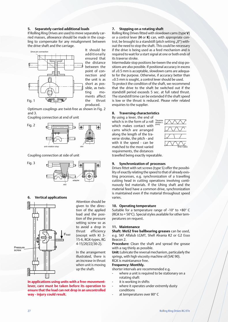
5. Separately carried additional loadsIf Rolling Ring Drives are used to move separately car-ried masses, allowance should be made in the coup-ling to compensate for any misalignment betweenthe drive shaft and the carriage.
It should beadditionallyensured thatthe distancebetween thepoint of con-nection andthe unit is asshort as pos-sible, as twis-ting mo-ments affectthe thrustproduced.
Optimum couplings are twist-free as shown in Fig. 2and 3.Coupling connection at end of unit
Coupling connection at side of unit
6. Vertical applicationsAttention should begiven to the direc-tion of the appliedload and the posi-tion of the pressuresetting screw so asto avoid a drop inthrust efficiency(except with KI 3-15-6, RGK-types, RG4-15/20/22/30-2).
In the arrangementillustrated, there isan increase in thrustwhen unit is movingup the shaft.
In applications using units with a free-movement-lever, care must be taken before its operation toensure that the load can not drop in an uncontrolledway - injury could result.
7. Stopping on a rotating shaftRolling Ring Drives fitted with slowdown cams (type V)or a control lever (H or K) can, with appropriate con-trol, be brought to a standstill (pitch setting „0“) with-out the need to stop the shaft. This could be necessaryif the drive is being used as a feed mechanism and isrequired to wait for a start signal at one or both ends ofits traverse stroke.Intermediate stop positions be-tween the end stop po-sitions are also possible. If positional accuracy in excessof ±0.5 mm is acceptable, slowdown cams are adequa-te for the purpose. Otherwise, if accuracy better than±0.5 mm is sought, a control lever should be used.To protect the condition of the shaft, we recommendthat the drive to the shaft be switched out if thestandstill period exceeds 5 sec. at full rated thrust.The standstill time can be extended if the shaft speedis low or the thrust is reduced. Please refer relatedenquiries to the supplier.
8. Traversing characteristicsBy using a lever, the end ofwhich is in the form of a rollwhich makes contact withcams which are arrangedalong the length of the tra-verse stroke, the pitch - andwith it the speed - can bematched to the most variedrequirements, the distancestravelled being exactly repeatable.
9. Synchronization of processesDrives fittet with set screws (type S) offer the possibi-lity of exactly relating the speed to that of already exis-ting processes, e.g. synchronization of a travellingcutting head in cutting operations involving conti-nuously fed materials. If the Uhing shaft and thematerial feed have a common drive, synchronizationis maintained even if the material throughout speedvaries.
10. Operating temperatureSuitable for a temperature range of -10° to +80° C(RGK to + 50°C). Special styles available for other tem-peratures on request.
11. MaintenanceShaft: MoS2 free ballbearing greases can be used,e.g. SKF Alfalub LGMT, Shell Alvania R2 or G2 EssoBeacon 2.Procedure: Clean the shaft and spread the greasewith a rag thinly as possible.Unit: Lubricate the reversal mechanism, particularly thesprings, with high viscosity machine oil (SAE 90).RGK is maintanance free.Frequency: Monthly. shorter intervals are recommended e.g. - where a unit is required to be stationary on a
rotating shaft - it is working in shifts- where it operates under extremly dusty
conditions - at temperatures over 80° C
Drive pin connection
anti-rotation stop slot
slot
adapter
Pressurescrew
Fload
time t (sec)
Traversestroke s(mm)
Fig. 1
Fig. 2
Fig. 3

Worldwide
The adresses of our agencies are available in the internet:www.uhing.com
Joachim Uhing KG GmbH & Co.Kieler Straße 2324247 Mielkendorf, GermanyTelefon +49 (0) 4347 - 906-0Telefax +49 (0) 4347 - 906-40e-mail: [email protected]: www.uhing.com B
K In
pre
ss 9
245
02/2013RG 07 e