Embed Size (px)
Citation preview
Analysis of Crack Detection of A Cantilever Beam
using Finite Element Analysis
Nitesh A. Meshram Student, ME (Machine Design)
Pillai’s HOC college of Engineering and Technology
Rasayani, Raigad(MS), India
Prof. Vaibhav S. Pawar Mechanical Engineering
Pillai’s HOC college of Engineering and Technology
Rasayani, Raigad(MS), India
Abstract- This paper describes finite elemental analysis of
a cracked cantilever beam and analyzes the relation between
the modal natural frequencies with crack depth, modal
natural frequency with crack location. Also the relation
among the crack depth, crack location and natural frequency
has been analyzed. Only single crack at different depth and at
different location are evaluated and the analysis revels
relationship between crack depth and modal natural
frequency. As we know when a structure suffers from damage
its dynamic property can change and it was observed that
crack caused a stiffness reduction with an inherent reduction
in modal natural frequencies. Consequently it leads to change
in dynamic response of the beam. The analysis was performed
using ANSYS software. The material of the beam is taken as
aluminum. The proposed technique represents actually a
modal analysis having great benefits for health monitoring of
structures. For this 3D model of cantilever beam with single
crack is created in ANSYS. Total 49 model of crack cantilever
beam has been analyzed. Thus result obtained from ANSYS
software we can draw the graph of modal natural frequency
Vs crack depth for constant crack location and modal natural
frequency Vs crack location keeping crack depth constant.
And finally the value obtained from ANSYS is checked with
result obtained from analytical method.
Kew words: Free vibrations; crack; modal natural
frequency; ANSYS software; cantilever beam.
I. INTRODUCTION
Being very commonly used in steel construction and machinery industries, health monitoring and the analysis of damage in the form of crack in Beam structures poses a vital mean. Since long efforts are on their way to find a feasible solution for crack detection in beam structures in this regard many approaches have so far being taken place. When a structure suffers from damages, its dynamic properties can change. Crack damage leads to reduction in stiffness also with an inherent reduction in natural frequency and increase in modal damping. The work gives a feasible relationship between the modal natural frequency and the crack depth at different location. Since free vibration analysis has frequently become a topic of many studies therefore attention is focused it only.
Crack localization and sizing in a beam from the free and forced response measurements method is indicated by Karthikeyan et al. [1]. In the beam Timoshenko beam theory is used for modeling transverse vibrations.FEM is used for the free and forced vibration analysis of the cracked beam and open transverse crack is selected for the crack model .Being iterative in nature the iteration starts
with a guess for the crack depth ratio and iteratively estimates the crack location and crack depth until the
desired convergence for both is reached.
In the most general terms, damage can be defined as changes appearing in a system that may affect its current or future performance. From this definition of damage once can see that damage is not meaningful without a comparison between two different states of the system, one of which is assumed to represent the initial (pristine) state, and the other the damaged state. The definition of damage can also be limited to changes to the material and/or geometric properties of the system, including changes to the boundary conditions and system connectivity, which adversely affect the current or future performance of that system.
The basic premise in modal analysis based damage detection is that damage will significantly change the stiffness, mass, or energy dissipation properties of a system, which in turn, modifies the measured dynamic response of the system. One of the most challenging aspects of modal analysis based damage detection is that damage is typically a local phenomenon and may not significantly influence the lower-frequency response of the structure that is normally measured during FFT analyzer tests.
II. LITERATURE REVIEW
Many attempts for modeling and studying the dynamic characteristics of cracked beams have been conducted. Expressions for bending vibrations of an Euler–Bernoulli cracked beam have been suggested by Matveev and Bovsunovsky (2002). Ross and Matthews (1995) identified some important cases and motives for SHM, in order to validate modifications to an existing structure, assess the safety and performance of structures affected by external induced vibrations, as well as an assessment of post earthquake structural integrity. Chondros and Dimarogonas(1998) used the Hu-Washizu-Barr variationa l analysis to develop the differential equation and boundary conditions for a cracked beam considered as a one-dimensional (1-D) continuum. Qiao (2009) has applied a signal-based pattern-recognition method to detect structural damages with a single or limited number of input/output signals. This method is based on the acquisition of sensitive features of the structural response under a specific excitation that represents a unique pattern for any particular damage scenario. Rao et al. (2010) have presented a method for crack identification in beam structures by
International Journal of Engineering Research & Technology (IJERT)
ISSN: 2278-0181
www.ijert.orgIJERTV4IS041005
(This work is licensed under a Creative Commons Attribution 4.0 International License.)
Vol. 4 Issue 04, April-2015
713

analyzing the fundamental mode of cracked cantilever beam using continuous wavelet transform. The crack in the beam is modeled as a combination of spiral and linear springs under consideration of the coupling of bending and longitudinal vibration of cracked cantilever beam. Rezaei (2010) has recorded critical data concerning the SH state on a continuous or periodic basis through a sensoring system. The data are then processed and interpreted using a proper algorithm, e.g. Hilbert–Huang Transform (HHT), in order to detect abnormalities and damages in the structure.
Rezaee et al. (2010) proposed a new approach based on the energy equilibrium method for free vibration analysis of a cracked cantilever beam taking into account both structural damping and damping due to the crack. Yazdi et al. (2009) presented transverse vibration of double cracked beam using assumed mode method. Sinha et al. (2002) reported a new simplified approach to model cracks in beams undergoing transverse vibration, in which they have used a modeling approach based on Euler–Bernoulli beam elements with small modifications to the local flexibility in the vicinity of cracks. Stephen (2009) has studied the vibration, aero-elasticity and crack detection of damaged composite wings. Wing damage has been considered as a through thickness edge crack for all proposed theoretical formulations and numerical investigation. Sanchez and Carlos (2006) examined structural damage identification methods based on changes in the dynamic characteristics of the structure and developed new approaches, which are based on the modal curvature matrix, the Frequency Response Function (FRF), the curvature and the Discrete Wavelet Transform.
In general, it can be stated that damage detection comprises five goals, each of which is gained with increasing difficulty and complexity. The first is the exploration of damage in a specimen. The second is the estimation of the severity extent of damage. The third goal is the ability to differentiate between different types of damage. The fourth is the calculation of the damage locations. The final is the estimation of the damage size. In the present paper it’s focused only on the first two goals.
III. EQUATION OF MOTION
Dynamic response of the structure affected by the
following aspects of the crack
Position of crack
Depth of crack
Number of cracks
A. specification
Material Of Beam- Aluminum
Span- 400mm
Density Of Material- 2700 kg/m³
Cross-Section Of Beam- 16*16 mm²
Young’s Modulus Of Elasticity- 70 GPa
Crack Nature-Transverse to beam axis and open nature
Poission’s ratio- 0.33
B. Governing equation of motion
The free bending vibration of an Euler-Bernoulli beam of a constant rectangular cross-section is given by the following differential equation as given in:
(1)
Where m is the mass of the beam per unit length (kg/m) wi is the natural frequency of the ith mode(rad/sec), E is the modulus of elasticity (N/m²) and I is the moment of inertia (m4). By defining
equation (1) is rearranged as a fourth-order differential equation as follows:
(2)
The general solution to equation (2) is
(3)
Where A, B, C, D are constants and is a frequency parameter. Since the bending vibration is studied,edge crack is modeled as a rotational spring with a lumped stiffness. The crack is assumed open. Basedon this modeling, the beam is divided into two segments: the first and second segments are left andright-hand side of the crack, respectively. Adopting Hermitian shape functions, the stiffness matrix of thetwo-noded beam element without a crack is obtained using the standard integration based on the variation
(4)
where
(5)
H1(x), H2(x), H3(x), H4(x) (6)
Hermitian shape functions defined as
H1(x) = 1 –3x2 /12 + 2x3/3+……. (7)
H2(x) = x – 2x2/1 + x3/12 +……. (8)
H3(x) = 3x2/12 – 2x3/13+…… (9)
H4(x)=-2x2/1+x3/12+……… (10)
International Journal of Engineering Research & Technology (IJERT)
ISSN: 2278-0181
www.ijert.orgIJERTV4IS041005
(This work is licensed under a Creative Commons Attribution 4.0 International License.)
Vol. 4 Issue 04, April-2015
714
Assuming the beam rigidity EI is constant and is given by EI0 within the element, and then the element stiffness is
Assuming the stiffness reduction caused by as open crack falls within a single element, and then the stiffness matrix of the cracked element can be written as
(11)
Where [ Kc] is the reduction in the stiffness matrix due to the crack. According to Penet al. [8], the matrix is[ Kc]
(12)
Where K is the change in stiffness due to crack at different location. It is supposed that the crack does not affect the mass distribution of the beam. Therefore, the consistent mass matrix of the beam element can be formulated directly as
(13)
(14)
In the dynamic analysis, the system matrix is usually required to be inverted. From this aspect, a diagonalized mass matrix has a computational advantage. In this study, a diagonalized mass matrix is adopted, which is developed from the consistent mass matrix .The natural frequency then can be calculated from the relation
(15)
The natural frequency of the ith mode for uncracked and cracked beams is finally obtained as follows
(16)
(17)
Where ωi0 is the ith mode frequency of the uncracked beam and ci is a constant depending on the mode number and beam end conditions (for clamped-free beam, ci is 3.516 and 22.034 for the first and second mode, respectively), ωi is the ith mode frequency of the cracked beam. ri is the ratio between the natural frequencies of the cracked and uncracked beam. l is the length of the beam.
IV. FINITE ELEMENT ANALYSIS
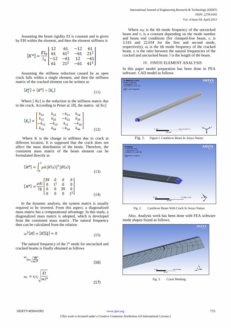
In this paper model preparation has been done in FEA software. CAD model as follows
Fig. 1. Figure I. Cantilever Beam In Ansys Nature
Fig. 2. Cantilever Beam With Crack In Ansys Nature
Also, Analysis work has been done with FEA software mode shapes found as follows.
Fig. 3. Crack Meshing
International Journal of Engineering Research & Technology (IJERT)
ISSN: 2278-0181
www.ijert.orgIJERTV4IS041005
(This work is licensed under a Creative Commons Attribution 4.0 International License.)
Vol. 4 Issue 04, April-2015
715

Fig. 4. First Mode Deformation Of Beam With Crack At 40mm And Depth 4mm
Fig. 5. Second Mode Deformation Of Beam With Crack At 40mm And Depth 4mm
Fig. 6. Third Mode Deformation Of Beam With Crack At 40mm And Depth 4mm
V. RESULT AND DISCUSSION
From theoretical and analysis data the curve-fitted results were tabulated, and plotted (in a three dimensional plot) in the form of frequency ratio (ωc/ω) (ratio of the natural frequency of the cracked beam to that of the un-cracked beam) versus the crack depth (a) for various crack location (X). This will show the variation of the frequency ratio as a function of the crack depth and crack location for beams with fixed-free ends.
Graph 1. First Mode Natural Frequency Ratio In Terms Of Various
Crack Position
Graph 2. Second Mode Natural Frequency Ratio In Terms Of Various
Crack Position
Graph 3. Third Mode Natural Frequency Ratio In Terms Of Various
Crack Position
International Journal of Engineering Research & Technology (IJERT)
ISSN: 2278-0181
www.ijert.orgIJERTV4IS041005
(This work is licensed under a Creative Commons Attribution 4.0 International License.)
Vol. 4 Issue 04, April-2015
716
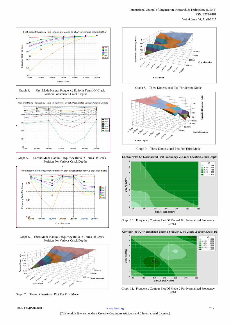
Graph 4. First Mode Natural Frequency Ratio In Terms Of Crack
Position For Various Crack Depths
Graph 5. Second Mode Natural Frequency Ratio In Terms Of Crack
Position For Various Crack Depths
Graph 6. Third Mode Natural Frequency Ratio In Terms Of Crack
Position For Various Crack Depths
Graph 7. Three Dimensional Plot For First Mode
Graph 8. Three Dimensional Plot For Second Mode
Graph 9. Three Dimensional Plot For Third Mode
CRACK LOCATION
CR
AC
K D
EP
TH
35030025020015010050
10
9
8
7
6
5
4
3
2
>
–
–
–
< 0.94
0.94 0.96
0.96 0.98
0.98 1.00
1.00
C5
Contour Plot Of Normalized First Frequency vs Crack Location,Crack Depth
Graph 10. Frequency Contour Plot Of Mode-1 For Normalized Frequency
0.9761
CRACK LOCATION
CR
AC
K D
EPT
H
35030025020015010050
10
9
8
7
6
5
4
3
2
>
–
–
–
–
< 0.965
0.965 0.970
0.970 0.975
0.975 0.980
0.980 0.985
0.985
C5
Contour Plot Of Normalized Second Frequency vs Crack Location,Crack Dep
Graph 11. Frequency Contour Plot Of Mode-2 For Normalized Frequency
0.9861
International Journal of Engineering Research & Technology (IJERT)
ISSN: 2278-0181
www.ijert.orgIJERTV4IS041005
(This work is licensed under a Creative Commons Attribution 4.0 International License.)
Vol. 4 Issue 04, April-2015
717
CRACK POSITION
CR
AC
K D
EP
TH
35030025020015010050
10
9
8
7
6
5
4
3
2
>
–
–
–
–
–
–
< 0.960
0.960 0.965
0.965 0.970
0.970 0.975
0.975 0.980
0.980 0.985
0.985 0.990
0.990
C5
Contour Plot Of Normalized Third Frequency vs Crack Location,Crack Depth
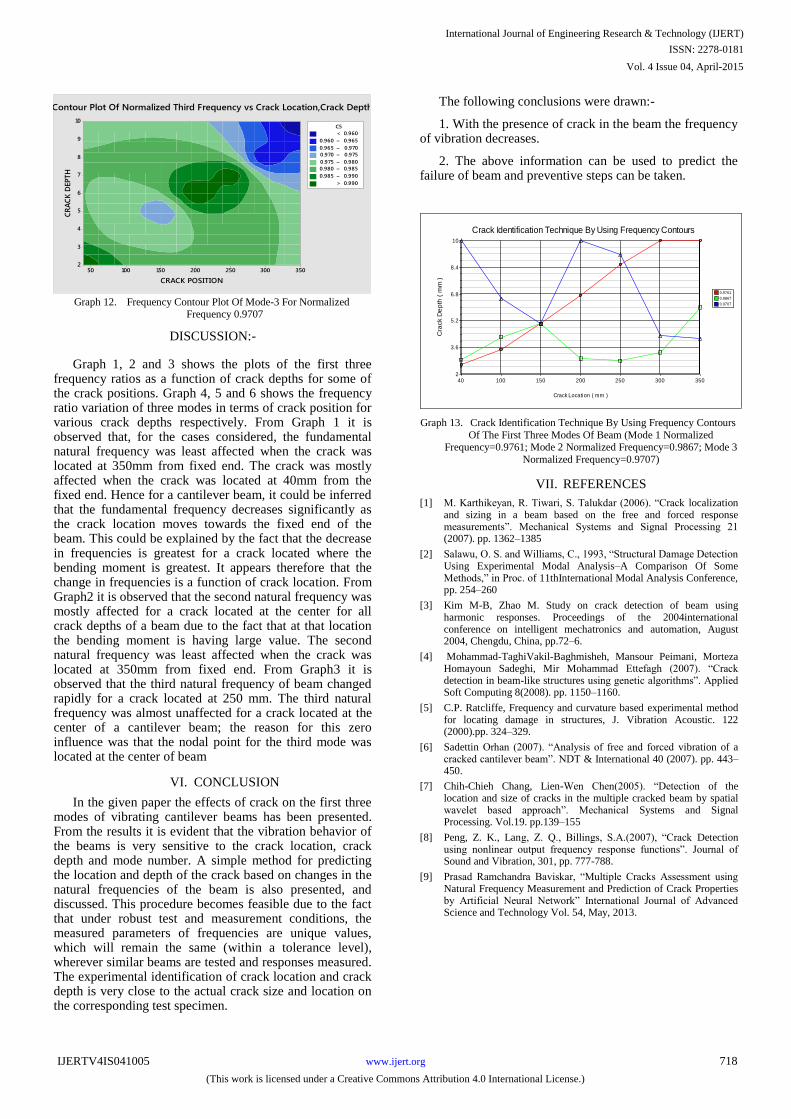
Graph 12. Frequency Contour Plot Of Mode-3 For Normalized
Frequency 0.9707
DISCUSSION:-
Graph 1, 2 and 3 shows the plots of the first three frequency ratios as a function of crack depths for some of the crack positions. Graph 4, 5 and 6 shows the frequency ratio variation of three modes in terms of crack position for various crack depths respectively. From Graph 1 it is observed that, for the cases considered, the fundamental natural frequency was least affected when the crack was located at 350mm from fixed end. The crack was mostly affected when the crack was located at 40mm from the fixed end. Hence for a cantilever beam, it could be inferred that the fundamental frequency decreases significantly as the crack location moves towards the fixed end of the beam. This could be explained by the fact that the decrease in frequencies is greatest for a crack located where the bending moment is greatest. It appears therefore that the change in frequencies is a function of crack location. From Graph2 it is observed that the second natural frequency was mostly affected for a crack located at the center for all crack depths of a beam due to the fact that at that location the bending moment is having large value. The second natural frequency was least affected when the crack was located at 350mm from fixed end. From Graph3 it is observed that the third natural frequency of beam changed rapidly for a crack located at 250 mm. The third natural frequency was almost unaffected for a crack located at the center of a cantilever beam; the reason for this zero influence was that the nodal point for the third mode was located at the center of beam
VI. CONCLUSION
In the given paper the effects of crack on the first three modes of vibrating cantilever beams has been presented. From the results it is evident that the vibration behavior of the beams is very sensitive to the crack location, crack depth and mode number. A simple method for predicting the location and depth of the crack based on changes in the natural frequencies of the beam is also presented, and discussed. This procedure becomes feasible due to the fact that under robust test and measurement conditions, the measured parameters of frequencies are unique values, which will remain the same (within a tolerance level), wherever similar beams are tested and responses measured. The experimental identification of crack location and crack depth is very close to the actual crack size and location on the corresponding test specimen.
The following conclusions were drawn:-
1. With the presence of crack in the beam the frequency of vibration decreases.
2. The above information can be used to predict the failure of beam and preventive steps can be taken.
40 100 150 200 250 300 3502
3.6
5.2
6.8
8.4
10
Crack Location ( mm )
Cra
ck D
ep
th (
mm
)
Crack Identification Technique By Using Frequency Contours
0.9761
0.9867
0.9707
Graph 13. Crack Identification Technique By Using Frequency Contours
Of The First Three Modes Of Beam (Mode 1 Normalized Frequency=0.9761; Mode 2 Normalized Frequency=0.9867; Mode 3
Normalized Frequency=0.9707)
VII. REFERENCES
[1] M. Karthikeyan, R. Tiwari, S. Talukdar (2006). “Crack localization and sizing in a beam based on the free and forced response measurements”. Mechanical Systems and Signal Processing 21 (2007). pp. 1362–1385
[2] Salawu, O. S. and Williams, C., 1993, “Structural Damage Detection Using Experimental Modal Analysis–A Comparison Of Some Methods,” in Proc. of 11thInternational Modal Analysis Conference, pp. 254–260
[3] Kim M-B, Zhao M. Study on crack detection of beam using harmonic responses. Proceedings of the 2004international conference on intelligent mechatronics and automation, August 2004, Chengdu, China, pp.72–6.
[4] Mohammad-TaghiVakil-Baghmisheh, Mansour Peimani, Morteza Homayoun Sadeghi, Mir Mohammad Ettefagh (2007). “Crack detection in beam-like structures using genetic algorithms”. Applied Soft Computing 8(2008). pp. 1150–1160.
[5] C.P. Ratcliffe, Frequency and curvature based experimental method for locating damage in structures, J. Vibration Acoustic. 122 (2000).pp. 324–329.
[6] Sadettin Orhan (2007). “Analysis of free and forced vibration of a cracked cantilever beam”. NDT & International 40 (2007). pp. 443–450.
[7] Chih-Chieh Chang, Lien-Wen Chen(2005). “Detection of the location and size of cracks in the multiple cracked beam by spatial wavelet based approach”. Mechanical Systems and Signal Processing. Vol.19. pp.139–155
[8] Peng, Z. K., Lang, Z. Q., Billings, S.A.(2007), “Crack Detection using nonlinear output frequency response functions”. Journal of Sound and Vibration, 301, pp. 777-788.
[9] Prasad Ramchandra Baviskar, “Multiple Cracks Assessment using Natural Frequency Measurement and Prediction of Crack Properties by Artificial Neural Network” International Journal of Advanced Science and Technology Vol. 54, May, 2013.
International Journal of Engineering Research & Technology (IJERT)
ISSN: 2278-0181
www.ijert.orgIJERTV4IS041005
(This work is licensed under a Creative Commons Attribution 4.0 International License.)
Vol. 4 Issue 04, April-2015
718