Embed Size (px)
Citation preview
Structural Analysis of Historic Construction – D’Ayala & Fodde (eds)© 2008 Taylor & Francis Group, London, ISBN 978-0-415-46872-5
Analysis of archaic fireproof floor systems
D. FriedmanOld Structures Engineering, New York, US
ABSTRACT: As engineers and builders developed modern steel framing in the late nineteenth century, theexisting options for floors to span between steel beams were forms of masonry vaults. Many possible alternatefloors were developed in the United States, but few had rational bases for design. Testing programs put in place bybuilding officials in NewYork City promoted the use of certain systems in NewYork and, by providing a rationalefor those systems, nationwide. Ten systems are described and analyzed.
Conservation and analysis of early modern structureoften begins with the main structural material: wehave one set of techniques for steel-framed build-ings, another for reinforced concrete, and another forthose buildings which are architecturally modern butare constructed using traditional wood and masonry.This focus is inevitable but tends to obscure secondarystructural materials and systems, which include theframing for facade ornament, structural adaptationsfor mechanical systems, and floor systems. This paperwill address the original design and current-day analy-sis of floor systems used in the United States between1890 and 1930 to fill in between iron and steel beams.
Since iron-framed floors were first used in thelate eighteenth century, floor systems have devel-oped in parallel with the iron-framing development.A wood-joist floor is most often associated with woodplank flooring, and masonry vault structures providemasonry floors, but iron or steel plates were notused spanning between iron and steel beams. Instead,combinations of other materials have been employedbetween the beams. Because the designers and builderswho used metal-framed floors were usually interestedin increasing their buildings’ resistance to fire, floorsystems have typically been made of masonry andconcrete.
Floor systems can be divided into three broadgroups: arches, catenaries, and beams. These cate-gories are, of course, the three basic methods ofsupporting vertical load across a horizontal span, butunlike complex structures such as bridges where two(or, rarely, all three) basic methods may be combined,floor systems tend to show only one method. Thatthe earliest floor systems were arches is unsurpris-ing since masonry vaults predate structural iron beams
by thousands of years; it is far more interesting fromthe modern perspective that catenary systems werepopular before beam systems.
There was no mechanism for the creation of nationalstandards in the United States during 1880s and 90sbecause there were no national building codes orauthorities. Various floor systems were promoted bymanufacturers and contractors, and reviewed by localbuilding officials who often had no technical train-ing. Empirical load and fire-resistance analysis wasused by some insurance companies, local buildingdepartments, and engineering schools. After 1896, theNewYork City Department of Buildings and ColumbiaUniversity’s School of Mines together conducted hun-dreds of tests on samples representing dozens of floorsystems, beginning with systems already in use andinviting floor-system manufacturers to submit theirproducts. Given the lack of national standards andthe rigorous testing regime, the results of these testswere influential far beyond New York and long afterthe tests ended. For example, standard E119 of theAmerican Society for Testing and Materials, currentlyused in the United States to determine fire-rating offloor assemblies, is closely related to the New Yorktesting standard and can be used to corroborate someof the older results.
This paper will review the floor systems that dom-inated “fireproof” construction in the Untied Statesbetween 1890 and 1930 as well as selected less-common systems. For each system, analysis usingcurrent methods will be compared with available anal-yses from the era of construction and historic testdata. Discussion will include implications for contin-ued use and alteration in terms of design load capacity,detailing, and fire resistance.
129

1 HISTORICAL CONTEXT
Structural steel technology and skeleton framing ofbuildings matured in the United States between 1890and 1910. At the beginning of this period, reinforcedconcrete was just beginning to be used and was still, toAmerican engineers and builders, partly experimental.There was not a general consensus on reinforced con-crete until the late 1910s. Given the late developmentof concrete relative to steel, designers and builders hadalready addressed the need for fireproof floors beforeconcrete became common. The use of bar-reinforcedconcrete slabs never became the dominant solution forfloors; after the invention of composite metal deck inthe 1950s, designers and builders rarely used any othersystem. As a result, from 1890 to 1960, floor systemswere used which are now unfamiliar to most engineersand builders.
As large steel-framed buildings were constructedin the 1890s, designers and builders became awareof an acute need for inexpensive, lightweight and“fireproof” structural floors. This need was not new:the Chicago fire of 1871 and the Boston fire of1872 – large-scale conflagrations that had betweenthem destroyed 18,000 buildings including much ofboth commercial downtown areas – had emphasizedthe need for buildings better able to resist fire. By the1880s, various proprietary forms of terra-cotta tile archfloors had been patented and were in use, although allwere functionally similar.
The word “fireproof,” as used at that time, meantwhat is now called “fire resisting:” a building or astructural element that could withstand some degreeof exposure to fire without failure. In this paper, “fire-proof” will be used in that sense, not in its literalmeaning of withstanding any exposure to fire.
As new ideas for fireproof floors were devel-oped, building officials and insurance companies wereforced to consider how floors built with new, often pro-prietary and patented technology, could be reviewedfor approval. In the end, the various parties, includ-ing engineers, companies selling proprietary systems,and insurance companies, cooperated with officials tocreate standardized tests. (Hill 1895) Many of thesetests were performed in the late 1890s and early 1900sby various agents under the supervision of the NewYork City Bureau of Buildings, in accordance with therequirements of the New York City Building Code atthat time. (no author 1905)
The portion of the code that defined floor systemsread: “All brick or stone arches, placed between ironfloor beams, shall be at least four inches thick andhave a rise of at least one and a quarter inches to eachfoot of span between the beams. Arches over five feetspan shall be properly increased in thickness . . . or thespace may be filled in with sectional hollow brick ofburnt clay or some equally good fire-proof material,
having a depth of not less than one and one-quarterinches to each foot of span, a variable distance beingallowed of not over six inches in the span between thebeams.” Some version of this was in the New Yorkcode from 1891 to 1916. (Birkmire 1898, no author1899, no author 1901)
The first clause allows for traditional brick andstone vaulting, which was rarely used because of theweight of the materials and the intensive labor requiredfor construction. The second clause allows somesegmental terra-cotta tile arches. The third clause,centered on the vague phrase “some equally goodfire-proof material,” and led to a proliferation of pro-prietary systems from manufacturers looking for aportion of the lucrative New York construction mar-ket. After several years of politicized review of varioussystems, the city Superintendent of Buildings, Steven-son Constable, arranged for a series of tests, beginningin 1896 and performed by the Bureau of Buildings inconcert with Columbia University. (Freitag 1899)
1.1 Testing
The building code enacted in 1898 in New Yorkallowed for brick and segmental tile vaulted floors.Other floors were addressed: “. . . or between the saidbeams may be placed solid or hollow burnt-clay, stone,brick, or concrete slabs in flat and curved shapes, con-crete or other fireproof composition, and any of saidmaterials may be used in combination with wire cloth,expanded metal, wire strands, or wrought-iron or steelbars; but in any such construction and as a prece-dent condition to the same being used, test shall bemade . . .” (no author 1899)The test defined in the codeconsisted of three stages of loading on a completedpanel of the floor in question: first, with the 7.2 kPaload in place, the floor was heated so that an averagetemperature of 927 C was kept for four hours; second,with the load in place, the floor was cooled by pres-surized streams of water meant to imitate fire-fighters’hoses; and third, the floor was reloaded to 29 kPa. Thephysical integrity of the floor was observed at all timesand deflection measurements taken during the thirdloading stage. (no author, 1897)
Because the New York code was interpreted lit-erally, each variation on a system had to be testedseparately. A floor system had to be tested for eachpossible load and span combination for which it wassold, leading to over 190 tests between 1895 and 1915.(Perrine & Strehan 1915)
Similar tests were used in other cities, by insurancecompanies in setting fire rates for buildings using newfloor systems, and by builders and inventors attempt-ing to prove the reliability of their systems to ownersand local building officials. The fireproofing aspectof the tests is obvious, but in many cases there was nostructural design for the floors beyond the empirical
130

Figure 1. Side-construction Flat Tile Arch. The “weakpoint” refers more to fireproofing than structural load.(Birkmire 1898).
proof of supporting a high level of live load whileexposed to fire. (Freitag 1899)
2 EXAMPLE FLOOR SYSTEMS
The floor systems described here are only a few ofthe many tested between 1890 and 1910. They includethe most common floors and a few oddities that oftenconfuse modern engineers.
The floors are grouped by type (arches, catenaries,and beams) and in the order that the types became pop-ular. The earliest floor systems used with iron beamsin the Untied States were arches. During the 1880sand 90s, various tile arch forms were the most popularfloors in use, and were still used into the 1920s. Thedraped-mesh (catenary) floors developed in the 1890sbecame the most popular form in the late 1910s and1920s, and were only permanently replaced by a beam-type floor when composite metal deck was developedin the 1950s.
2.1 Arch floors
Neither brick vault floors nor plain segmental terra-cotta tile arches were tested in NewYork, as both wereallowed without limitation. They were typically nottested elsewhere, as they were considered ordinary andfamiliar floors.
Both generic and proprietary flat terra-cotta tilearches were tested in New York because neither metthe geometric requirements for exemption. These sys-tems consisted of precast terra-cotta blocks with thinwebs, arranged as flat-arch voissoirs. There were twomajor types: side construction, with terra-cotta voidsperpendicular to the vault span, and the newer end con-struction, with voids parallel to the span. (Figs 1, 2)The tiles were typically set low, to cover the bottomof the steel beams, and fill was placed over the top toprotect the tops of the beams and provide a base forwood flooring. (no author 1897)
The Guastavino Timbrel Vault was an interestingvariant on the standard terra-cotta tile-arch floor, usingCatalan hard-burned tiles and thin-shell constructionto meet the American testing standards. (Fig. 3) Itwas not popular for ordinary floors, although the
Figure 2. End-construction Flat Tile Arch (Birkmire 1898).
Figure 3. Uastavino section, elevation, and plan (Guas-tavino 1892).
Guastavino company achieved fame in the construc-tion of domes and long-span floors, roofs, and ceilings.Two or three layers of thin tiles were arranged withstaggered joints. (no author 1889, no author 1897,Freitag 1921, Collins 1982)
The Roebling Arch Floor is one of a class of earlyconcrete floors produced by several manufacturers.(Fig. 4) Wire-mesh arches spanned between the beambottom flanges and served as forms for stone concretevaults. More wire mesh was hung from the beams tocreate a plaster ceiling for fireproofing. (no author1897, Birkmire 1898, Hool 1913).
2.2 Catenary floors
The Metropolitan System was an early draped-wirefloor, approved in 1899. (Fig. 5) The reinforcing con-sisted of twisted pairs of wires individually strungacross the building, anchored at slab edges, and drap-ing over the floor beams and under a hold-down bar atmid-span. Since the wires carried all loads, the slabs
131

Figure 4. Roebling Arch: wood sleepers for finish flooring,concrete fill, wire-mesh arch, hung ceiling. (Birkmire 1898).
Figure 5. Metropolitan Floor (Freitag 1899).
Figure 6. Cinder-concrete, draped-mesh slab, (Buel & Hill1906).
were structurally unstressed and were composed ofgypsum plaster mixed with wood chips. (no author1897, Freitag 1898, Birkmire 1899, no author 1895)
Draped-mesh floors were first developed underproprietary names, but the presence of the existingcatenary patents meant that the basically similar meshfloors quickly became generic commodities. (Fig. 6)Various proprietary forms of mesh were used early on,but since the floor only required a specified standardsize of wire at a specified spacing, the generic floorswere ultimately more common than the named ones.As with the Metropolitan floor, the mesh passed overthe top of the floor beams, near the top of the slab,and at midspan draped down to the bottom of the slab.Because the mesh wires take all of load in tension, theslab serves only to provide a walking surface and fire-proofing. Because the concrete is not stressed, materialof poor quality and low strength, such as cinder con-crete, was frequently used. (Perrine & Strehan 1915,Waite 1914)
Figure 7. Rapp Floor: wood sleepers to attach finish floor-ing, fill (“concrete”), brick, and inverted Ts. (Birkmire1898).
Figure 8. Expanded Metal Floor (Freitag 1899).
Figure 9. Columbian Floor, with wood flooring on sleepers,and rebar supported by light-gage straps over the beam tops.The bottom transverse section shows the double-cross bars.(Freitag 1899).
2.3 Beam floors
The Rapp Floor consisted of common brick, support-ing a layer of fill and supported by light-gage steelinverted Ts, which span between the bottom flanges ofthe floor beams. (Fig .7)(Birkmire 1899)
The Expanded Metal Company Floor is a thin con-crete slab reinforced with a sheet of “expanded metal,”created by slitting a light-gage steel sheet and pullingthe sheet to open the slits. (Fig. 8)The reinforcing sheetsat directly on the tops of the floor beams. The systemhad an overall slab thickness of only 5 inches, in partbecause the beams were at a close spacing. (no author1897, Freitag 1899)
The Columbian Floor system was an early bar-reinforced concrete slab. Bars with a cross or double-cross section were hung from the beam tops usinglight-gage steel straps to serve as flexural reinforc-ing in a cinder-concrete slab. (Fig. 9) The typicalbeam encasement provided the only shear transfer. (noauthor 1897, Birkmire 1898, Hool 1913)
132
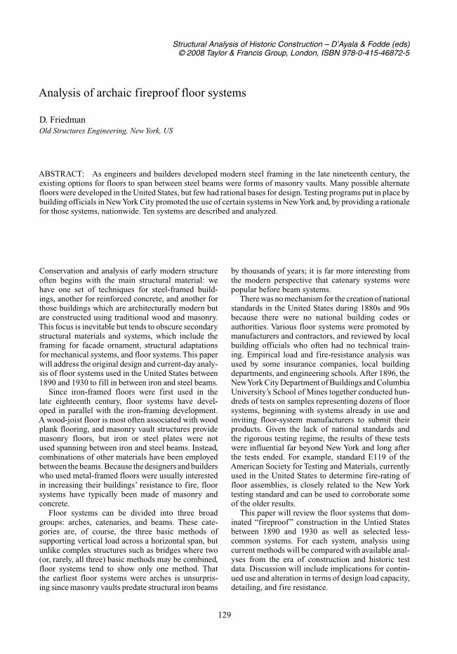
Figure 10. Roebling Flat Slab Floor, showing strap rein-forcing twisted at the beam top. (Freitag 1899).
The Roebling Flat Slab Floor was basically similarto the Columbian floor, except that the reinforcing wasrectangular bars set vertically and twisted horizontallyto rest on the floor beams. (Fig. 10) (Freitag 1899, Hool1913)
3 RE-USE AND ANALYSIS
Since the original use of these floors depended onlyon empirical testing, analysis came after the fact. Forthe arch floors, there was rarely analysis at all until thefloors fell out of use, while justifications for the beamand catenary floors have changed over time.
3.1 Current codes
During the course of the twentieth century, numericalanalysis replaced the empirical tests remaining in thestructural design. Steel beam design had been ratio-nalized in the nineteenth century, and concrete beamdesign after 1900. At the time of the floor testing, allAmerican building codes were local, created by eithermunicipalities or states. Regional and national codeswere only established later, and have only allowedanalysis-based structural design. In the case of NewYork, the 1916 building code removed the testingrequirement in favor of analytic design. This code wasrevised but kept in use until 1968, when an entirelyrewritten code was put into effect. All references totile arches or other masonry floors were removed, butdraped-mesh slabs remained as “Short-span concretefloor and roof construction supported on steel beams.”The formulas for minimum allowable slab thicknessand wire stress were the same as the old code, andvalues were given for stone concrete and unspecified-material “lightweight aggregate concrete.” This coderemained in effect, with revisions, until July of 2007,when it was superseded by a local version of the 2003International Building Code, with a one-year overlapuntil the summer of 2008.The new code retains one lastvestige of the old floors: a statement that wire meshreinforcing “is permitted to be curved from a pointnear the top of the slab over the support to a pointnear the bottom of the slab at midspan, provided suchreinforcement is either continuous over, or securely
anchored at support.” (no author 2004, no author2007a)
The load analysis for the different floor types thatfollows is based on current codes except as noted.
Modern code analysis is somewhat simpler withregard to the fireproofing capacity of the old floors.Under currentAmerican practice, fire ratings for struc-tural assemblies are determined using tests definedin the standard specification ASTM E119. The stan-dard has been published and periodically revised bythe ASTM since 1917 and carries no authority of itsown, but is regularly adopted into building codes andother statutes. (no author 2007b)
The provisions of E119 are similar in many respectsto that of the New York City tests. The floorsare to be loaded “to simulate a maximum loadcondition . . . under nationally recognized structuraldesign criteria,” the heating is to follow an upwardcurve from 538 C at five minutes to 1093 C at 4 hours(and up to 1260 C at eight hours if a rating past fourhours is sought), the floor is to be cooled by a pres-surized hose stream, and the test report is to includeinformation on damage and deflection. Since (a)the maximum design load on most floors is less thanthe 7.2 kPa used in the New York tests and (b) thereare no standard uniform loads of 29 kPa as was used inthe New York reloading test, the current loading crite-rion is less stringent than the NewYork tests. The totalamount of heat to be absorbed in the early stages (asmeasured by the area of the time/temperature curve)is less in the ASTM tests than in the New York tests,the New York tests are more conservative for systemswith low fire-ratings. At four hours, the total energyis nearly identical between the two tests, so that a sys-tem that passed the New York test would be assigneda four-hour rating using the ASTM test. Only whenthe tests are continued past four hours does the totalenergy in the ASTM test exceed that of the New Yorktest. As few floor systems are now required to have rat-ings greater than three hours, it can be generally statedthat any floor that passed the New York test has effec-tively passed the ASTM test and can be considered tohave a four-hour fire rating if it has been maintainedin its original state.
The most significant difference between the NewYork tests and the ASTM test is one of perception: theolder tests were used as proof of both fire-resistanceand structural load capacity, while the current testsare used only to determine fire ratings for assembliesassumes to have been already numerically designedfor structural loads. This gap is less of a problem forexisting buildings than it might appear, since the cur-rent building codes allow existing structure to be loadtested to prove capacity, in a manner reminiscent ofthe historic tests.
The use of historic test data, common among engi-neers, has been given a government imprimatur in the
133

form of a guide to fire ratings on historic structurescompiled by the US National Institute of BuildingSciences and published by the federal Department ofHousing and Urban Development. (no author 2000)This guide is a compilation of historic and moderntests on various types of building elements, includingfloor systems. Gypsum slabs, terra-cotta tile arches,and tile and concrete rib systems are all included andassigned fire ratings of up to four hours. While theguide does not comprehensively address all of thefloor systems of interest, it does provide an officialopinion on some and it does show that the reuse of his-toric test data can be an officially-accepted method ofresearch.
3.2 Arch analysis
Arch analysis is one of the oldest problems in structuraldesign. In ordinary masonry practice, symmetrical anduniformly loaded arches are rarely dependent on thecompressive strength of the material, but the terra cottatile used in the floors was often weaker than stone orordinary brick, and was used in thin webs vulnerableto local concentrations in stress.
Among the various formulas developed for masonryarches exists a class of simplified formulas for minorarches – those with short spans and low rises. In suchcases, the formulas also include the assumptions fora flat arch of uniform loading and a specific locationfor the thrust line.
A simplified formula suggested while terra-cottafloors were still in use is H =WS / 8D, where H isthe thrust, W is the total uniform load, S is the span,and D is the effective rise of the arch. This formulaassumes that the thrust line curve was 61 mm less thanthe height of the terra cotta blocks, as D is the totalarch depth minus 61 mm. (no author 1919) Note thatthe load and analysis are for a unit width of arch. In thiscase, the main simplifying assumption, represented bythe use of D rather than the arch depth is that the thrustline curve is proportional to the block depth excludingthe lower portion of the blocks which extend below thesteel beams. For example, a typical application span-ning 1830 mm between beams and consisting of woodflooring, 125 mm inches of cinder fill, 254 mm deepterra cotta blocks making up the flat arch, 12 mm ofplaster on the block soffits as a ceiling, and an officelive load of 2.9 kPa, had a total weight, including steelframing, of 6.8 kPa. This translates to an arch thrust of15 N/mm to be carried by tie rods from beam to beam.
A typical terra cotta block had 19 mm thick websat 100 mm spacing. Since the horizontal webs are ori-ented incorrectly to carry the arch thrust, the thrustmust lie entirely within the vertical webs. With aneffective web area of 254–61 or 193 mm by 19 mm, thecompression in the terra cotta is .41 MPa, well withinthe allowable range for clay masonry.
A modern simplified formula for arch thrust used bythe Brick Industry Association is H = 3 WS/8d, whereH is the thrust,W is the total uniform load, S is the span,and d is the arch depth. (no author 1986) Again, theanalysis is for a unit width of arch. In this case, the mainsimplifying assumption, represented by the “3” in theformula, is that the thrust line is within the middlethird of the arch height. This is more conservative thanthe older formula in that it increases the thrust forceby confining its path. Using the previous example, thethrust is 34 N/mm and the net compression on the websis 0.93 MPa, which is still within the capacity of claymasonry.
The formulas for segmental arches do not requirethe complicated assumptions regarding the location ofthe thrust curve: it is taken within the curve of the vault.Since the floor vaults based on segmental curves typi-cally support fill above, a thrust line that extends pastthe vault material on the top side and passes throughthe fill may still be viable.
Using the Guastavino vault as an example of asegmental-arch floor, with a span of 1830 mm anda rise of 150 mm, the average total load is 7.9 kPa,with the extra dead load resulting the deeper fill overthe arch ends. The basic thrust formula, H =WS/8d,gives a thrust of 22 N/mm. Unlike terra cotta vaults, thestress in a Guastavino vault is evenly distributed alongthe solid masonry section, so with a vault thickness of75 mm, the compressive stress is 0.29 MPa.
Finally, the Roebling arch is the simplest of the type.The minimum arch depth is the distance from the floorto the top of the arch center, and the material is stoneconcrete, with a compressive strength in the range of14 MPa, so an analysis similar to the Guastavino floorshows a gross over-capacity.
3.3 Catenary analysis
Analyses for catenaries with fixed supports were avail-able in the late nineteenth century, both as generalformulas based on statics and simplified formulas thatbecame part of building codes and manufacturers’ rec-ommendations during the first half of the twentiethcentury.
One of the simplified catenary formulas that waspublicized by the wire-products division of UnitedStates Steel was also incorporated in the New YorkCity Building Code in 1916 (no author 1944) This for-mula is W = 3CAs / L2where W is the total allowablefloor load, L is the beam-to-beam centerline spac-ing , As is the unit wire cross-sectional area, andC is a constant representing the maximum allowablewire stress and equal to 138 MPa. The referenced ver-sions of this formula refer to stone or cinder-concreteslabs; however, the results also agree closely with thestated capacities of the Metropolitan Floor’s gypsumslab. It should be noted that the maximum allowable
134

tension in the wire of 138 MPa is very low for steelwire produced after 1900. The minimum yield stressexpected in historic wire systems has been conserva-tively established as 345 MPa. (no author 1981) Giventhat current reinforced-concrete codes have combinedsafety factors in the range of 1.5 to 1.8, it is evidentthat there is excess capacity in the wire in the originaldesigns.
For example, in a 100 mm-thick draped-mesh slabwith a 1830 mm span, the total load based on woodflooring, the cinder-concrete slab, 12 mm of plaster onthe soffit as a finish ceiling, and an office live loadof 2.9 kPa was 5.1 kPa. With mesh reinforcing of 8-gage (4.2 mm diameter) wire at 75 mm spacing, themaximum allowable load is 41 KPa.
A more basic formula derived from statics byapproximating the catenary curve as a parabola (a rea-sonable assumption since the actual wire curve is notparticularly accurate) is T = (wsL2 / 8 h) + wsh whereT is the tension in a wire, w is the combined dead andlive load, s is the wire spacing, L is the span, and h isthe wire sag. By setting T equal to the allowable ten-sile stress (Ta) multiplied by the wire cross-sectionalarea (As), the maximum floor load can be deter-mined as W = 8 hTaAs / (sL2 + 8 sh2). In the previousexample, using the 138 MPa maximum stress in thewire and assuming a wire sag of 75 mm for the 100 mmslab thickness, the allowable load per square footis 25 kPa.
In a Metropolitan floor example using the simpli-fied formula, with pairs of 12-gage (2.8 mm diameter)wire at 25 mm spacing and a 1830 mm span, the totalload capacity is 36 kPa. Using the basic formula, thetotal load capacity is 22 kPa.
In short, the catenary floors show the excess capac-ity required to pass the load test.
3.4 Beam analysis
Beam theory is generally more complex than arch orcatenary theory as long as fixed supports are assumed.In addition, the design of reinforced concrete in theUnited States at the time of the testing was ham-pered by over-conservative allowable stresses. Whenthe New York code was amended in 1911 to allow useof reinforced-concrete floors proved by analysis ratherthan by testing, the maximum compression in the con-crete was limited to 4,5 MPa, the maximum tensionin the reinforcing was limited to 110 MPa, and n, theratio of the elastic moduli, was fixed at 15. (Waite1914) Only elastic concrete theory was in commonuse at the time, and using the notation common forthat theory, the location of the neutral axis from thecompression face of the slab is kd, where d is the depthfrom the compression face of the slab to the centroid ofthe reinforcing and the ratio k = (2 pn + p2n2)0.5 − pn,where p is the reinforcing ratio.The arm of the resisting
moment (the distance from the centroid of the tri-angular elastic compression block to the centroid ofthe reinforcing) is jd, where j = 1 − k/3. The resistingmoment is the lesser of the two calculated momentsMs = Asfsjd and Mc = fckjbd2/2, where Ms is the max-imum resisting moment if the slab is under-reinforcedand steel yield controls, As is the reinforcing area insquare inches per foot, fs is the allowable tensile stressin the steel, Mc is the maximum resisting moment ifthe slab is over-reinforced and concrete crushing con-trols, and fc is the allowable compressive stress in theconcrete.
For example, the code-enforced maximum stressvalues would show a 100 mm stone-concrete slabwith 6 mm diameter bars at 150 mm on center, andspanning 2440 mm, to have a maximum allowablemoment of 4.9 kN-m/m, or a maximum total load of6.5 kPa, compared to the 7.2 kPa allowed from testingthe same floor. This is not a hypothetical compari-son: the Monier Floor System, which was essentiallya numerically-designed, modern reinforced concreteslab as used in the in Europe, was tested for use inNew York by 1900. If the current American ConcreteInstitute code and ultimate-stress theory is used on thesame slab, assuming the 14 Mpa concrete often usedin that era and a steel yield stress of 138 MPa based onthe weakest available reinforcing steel bars, the maxi-mum allowable moment is 8.5 kN-m/m, and, assumingthat the dead load to live load ratio is approximately 1,a maximum unfactored total load of 8.0 kPa.
The Columbia and Roebling Flat Slab floors canbe analyzed like any other reinforced slab as long ascertain restrictions are observed: the bars must be con-verted to a cross-sectional area per unit width of slab,the slab strength must be adjusted to match the mate-rial, and the lack of deformations must be accountedfor by a check on the development length of the bars.
The Expanded Metal Floor can be analyzed usingordinary reinforced-concrete formulas and convertingthe cross-sectional area of the expanded-metal sheetinto the bar equivalent.
The analysis of the Rapp Floor, a beam-type floorthat did not rely on reinforced concrete, is simpler. Thebricks spanning 200 mm and the light-gage Ts span-ning the beam-to-beam spacing can be checked formaximum stress using a simple beam formula.
4 CONCLUSIONS
The simplest result of the analysis is the conclusionthat these floors can be demonstrated to pass mod-ern requirements for fire resistance and load capacity.In the course of renovation projects, many engineersand contractors prefer the removal of unfamiliar andarchaic structural elements rather than their reuse, evenif no damage is visible. The explanation for this behav-ior is often “better to be safe than sorry,” as if the reuse
135

of existing structure that has functioned properly fordecades is somehow unsafe. It must be emphasizedthat unknown structural capacity and fireproofing arenot excuses for the wholesale demolition of historicfabric that often takes place, leaving a historic facadecovering an essentially new building. It is incumbentupon the engineers involved to investigate unfamil-iar structures and find methods by which they can beanalyzed.
This is not to say that there are no difficulties inreuse once an archaic floor is analyzed. There may bedamage to the floors, particularly with the more frag-ile systems such as tile arches, that reduce their loadcapacity or fire protective abilities. Modern seismicanalysis of a building frame may depend on diaphragmaction of the floor, which may or may not be availabledepending on the details of original construction. Theneed for a diaphragm implies a second investigationinto details and a second analysis, not automatic dis-qualification. Finally, alterations accompanying reusemay require special details, such as providing newanchorage for catenary floors when new openings arecut for circulation or HVAC shafts. Some of the floorsare particularly vulnerable to damage during alter-ation: theTs in a Rapp floor can shift when an adjoiningportion of the floor is removed.
In a broader sense, the continued viability of manyof these floors emphasizes that the products of empir-ical design can still be used today. The rise of “scien-tific” numerical analysis in the twentieth century canobscure the value of older forms of engineering design,even as we still rely on some of the methods and dataproduced by those older forms.
REFERENCES
no author. 1889. “A New System of Fireproof Floor Construc-tion.” Engineering News, November 9, 1889: 434–35.
no author. 1895. “The Metropolitan Concrete and WireFloor.” Engineering News, November 14, 1895: 333.
no author. 1897. “Comparative Standard Fireproof FloorTests of the New York Building Department.” Engineer-ing Record, September 18, 1897: 337–40; September 25,1897: 359–63; October 2, 1897: 382–87; October 9, 1897:402–405.
no author. 1899. Building Code of the City of NewYork. NewYork: New York City Bureau of Buildings.
no author. 1901. Building Code of The City of NewYork. NewYork: Department of Buildings.
no author. 1905. Report of the Bureau of Buildings of the Cityof NewYork for the Borough of Manhattan for the Quarterand Year Ending December 31, 1904. New York: MartinB. Brown Co., 1905.
no author. 1919. Pocket Companion for Engineers, Architectsand Builders Containing Useful Information and TablesAppertaining to the Use of Steel. Pittsburgh: CarnegieSteel Company.
no author. 1944. American Welded Wire Fabric for ConcreteReinforcement. Pittsburgh: United States Steel Corpora-tion.
no author. 1981. Evaluation of Reinforcing Steel Systems inOld Reinforced Concrete Structures. Chicago: ConcreteReinforcing Steel Institute.
no author. 1986. “Technical Note 31a – Structural Design ofBrick Masonry Arches.” Reston, Virginia: Brick IndustryAssociation.
no author. 2000. Fire Ratings of Archaic Materials andAssemblies: Guideline on Fire Ratings of Archaic Mate-rials and Assemblies. Washington, D.C.: U.S. Departmentof Housing and Urban Development, Office of PolicyDevelopment and Research.
no author. 2004. Building Code of the City of NewYork. NewYork: New York City Department of Citywide Adminis-trative Services.
no author. 2007a. New York City Building Code. New York:New York City Department of Citywide AdministrativeServices.
no author. 2007b. “Standard Test Methods for Fire Tests ofBuilding Construction and Materials,” ASTM E119–07a.West Conshohocken, Pennsylvania: American Society forTesting and Materials.
Birkmire, W. 1898. The Planning and Construction of HighOffice Buildings. New York: John Wiley & Sons.
Buel, A.W. & Hill, C.S. 1906. Reinforced Concrete, 2ndedition. NewYork: The Engineering News Publishing Co.
Collins, G.R. 1982. “Guastavino y Moreno, Rafael and Guas-tavino y Esposito, Rafael,” Macmillan Encyclopedia ofArchitects. New York: Macmillan Publishing Co.
Guastavino, R. Jr. 1892. “Hollow Cohesive Arch,” UnitedStates Patent 471,173. Washington DC: United StatesPatent and Trademark Office.
Freitag, J.K. 1921. Fire Prevention and Fire Protection, 2ndedition. New York: John Wiley & Sons.
Freitag, J.K. 1899. The Fireproofing of Steel Buildings. NewYork: John Wiley & Sons.
Hill, G. 1895. “Tests of Fire-Proof Flooring Material,” Trans-actions of the American Society of Civil Engineers 34:542–568.
Hool, G. A. 1913. Reinforced Concrete Construction,Volume II: Retaining Walls and Buildings. New York:McGraw-Hill.
Perrine, H. & Strehan, G. 1915. “Cinder Concrete FloorConstruction Between Steel Beams.” Transactions of theAmerican Society of Civil Engineers. 79: 523–621.
Waite, G.B. 1914. “Cinder Concrete Floors.” Transactions ofthe American Society of Civil Engineers. 77: 1773–1823.
136