Embed Size (px)
Citation preview
Analysis of Arc Welded Thin-Walled Cylinders to Investigate the Effects
of Welding Process Parameters on Residual Stresses
Afzaal M. Malik1,a, Ejaz M. Qureshi2,b and Naeem Ullah Dar3,c 1Professor, National University of Sciences & Technology, CEME, Rawalpindi, Pakistan
2Graduate Student, National University of Sciences & Technology, CEME, Rawalpindi, Pakistan
3Graduate Student, University of Engineering & Technology, Taxila, Pakistan
Keywords: Finite Element Simulation, Welding Parameters, Residual Stresses, Thine Cylinders.
Abstract. The research work presents a computational methodology based on three-dimensional
finite element model to simulate the gas tungsten arc welding (GTAW) of thin-walled cylinders.
The aim was to study the effects of two basic welding parameters (welding speed and welding
current) on weld induced residual stresses. The complex phenomenon of arc welding was
numerically solved by sequentially coupled transient, non-linear thermo-mechanical analysis. The
accuracy of the numerical model was validated through experiments for temperature distribution
and residual stresses. The results reveals that the present simulation strategy can be used as a proper
tool to get the optimized welding process parameters and minimize the in service failures of thin-
walled structures due to residual stresses.
Introduction
Arc welding is a reliable joining process enabling the industries around the globe to produce high
strength joints in nuclear, aerospace and pressure vessel applications. The problem of reduced
strength of the structures, in and around the weld zone due to residual stresses is a major concern of
the welding industry for decades. Therefore prediction of the transient and residual stress fields in
circumferentially welded thin-walled cylinders is of critical importance, to ensure the in-service
structural integrity due to their wide industrial applications. Finite element (FE) is a proven effective
tool for accurate prediction of thermo-mechanical behavior in circumferentially welded thin-walled
structures [1] and is being used in the prediction of welding residual stress and distortion for more
than two decades [2]. Previously a number of experimental and numerical based studies were
conducted for the measurement and prediction of transient and residual stress fields in shell
structures [3-8]. Different aspects including the effects of process and geometric parameters were
addressed, showing that weld induced residual stresses are unavoidable, but can not be tolerated in
certain applications due to the risk of in-service catastrophic circumstances. Most of the previous
work exploit the axis/lateral symmetry due to the constraints of computational resources both
storage and CPU. These assumptions reduces the computational demand at the cost of results
accuracy because the model was over simplified by limiting the solution to only a section of the
whole domain. Also these simplifications are not capable to capture the significant effects of weld
start/stop and tack modeling. In this research full three-dimensional FE models were developed for
the parametric studies.
Analysis Strategy in the Present Research
The research work presents a three-dimensional transient non-linear thermo-mechanical simulation
of circumferentially, butt-welded thin-walled cylinders; primarily focusing on the effects of two
basic welding processes parameters on residual stresses. Net heat input to the weldments due to
varying welding current or alternatively by controlling the welding speed can be optimized to obtain
acceptable residual stress level. Thin-walled cylinders of 200 mm outer diameter, 3 mm wall
Materials Science Forum Vols. 575-578 (2008) pp 763-768Online available since 2008/Apr/08 at www.scientific.net© (2008) Trans Tech Publications, Switzerlanddoi:10.4028/www.scientific.net/MSF.575-578.763
All rights reserved. No part of contents of this paper may be reproduced or transmitted in any form or by any means without the written permission of TTP,www.ttp.net. (ID: 152.14.136.96, NCSU North Carolina State University, Raleigh, United States of America-31/08/13,16:47:27)
thickness and 150 mm linear length were used with base welding parameters of 3 mm/sec, 200
amperes and 12.5 volts with 80% arc efficiency for the numerical simulations. Three different
values of welding speed (2, 3 and 4 mm/sec) and welding current (WP1=150, WP2=200 and
WP3=300 amperes) are used in parametric studies for residual stress analysis. Each parameter value
is varied explicitly by keeping all the other parameters constant (at base values) to investigate the
effects of that particular parameter. To get a clear understanding of the effect of variable parameters,
the total heat input to the weldments is used as a reference controlling parameter. The heat input is
manipulated in such a manner that the minimum total heat input (0.625 MJ/m) incase of maximum
welding speed (4 mm/sec) equals to the total heat input incase of minimum welding current of 150
amperes, i.e. lowest heat input corresponds to the parametric study with maximum welding speed.
In thermal analysis, modeling of heat losses from the exposed surfaces by convection and radiation
are taken into account. Radiation is the primary mechanism for heat loss in the weld region and near
by areas, whereas convection dominate as a heat loss mechanism away from the weld line. The
combined heat transfer coefficient for convection and radiation [9] is calculated and applied on all
the applicable surfaces. The heating time along the weld path is about 209.4 sec with a torch speed
of 3.0 mm/sec and the complete welding sequence is divided into 300 incremental equally spaced
load steps of 0.698 sec. Stepped load option available in ANSYS® is used for effective application
of thermal load during the load step. After extinguishing the arc additional 47 load steps of different
time lengths are used for cooling of the weldments. The total cooling time to return to the ambient
temperature of 300oK is about 50.37 minutes from the start of the cooling phase. In structural
analysis, the only boundary condition is the constraints applied to represent the clamping of the
cylinders to be welded in welding positioner. To match the experimental boundary conditions, all
the nodes at the positioner and remote
end of the cylinders, on a Cartesian
coordinate axis, are constrained in axial
direction. Additionally two nodes 180o
apart at the positioner end are also
constrained in axial radial and
circumferential directions for FE model
stability. For all the parametric studies,
mechanical constraints, only at the
positioner end are applied. The
temperature dependent thermo-
mechanical properties of AH36 steel
taken from [10], used in the simulation
are shown in Fig. 1.
Finite Element Discretization
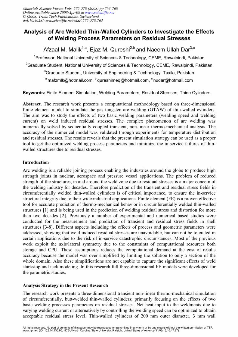
Full 3D FE model for the circumferential welding of two cylinders
with "V" groove developed in ANSYS® is shown in Fig. 2. The
element type in thermal analysis is SOLID70 (linear 8 node brick
element with one degree of freedom, i.e., temperature at each node).
In structural analysis SOLID45 (linear 8 node brick element with
three degrees of freedom at each node i.e. translations in the nodal x,
y, and z directions.). Due to anticipated high temperature and flux
gradients in and around the fusion zone (FZ) and heat affected zone
(HAZ), a relatively fine mesh is used within a distance of 10 mm on
both sides of weld line (WL). Two tack welds at weld start i.e. 0º and
middle i.e. 180º are modeled, each 7.85 mm in circumferential
direction. FE model includes total 54720 elements and 71040 nodes.
Fig. 1. Material properties in present research
Fig. 2. Finite Element Model
0
110
220
330
440
550
0 400 800 1200 1600 2000
Temperature (oC)
Elastic Modulus x 500 MPa
Thermal Expansion x 1.0E-13 / ºC
Poisson Ratio x 1.0E-3
Yield Stress of BM (MPa)
Yield Stress of WM (MPa)
Yield Stress of BM-0.1% SH (MPa)
Yield Stress of WM-0.1% SH (MPa)
"V" groove
764 Physical and Numerical Simulation of Materials Processing
af
Z
X
Y
ar
c b
Heat Flux
(W/m3)
Heat Source Model
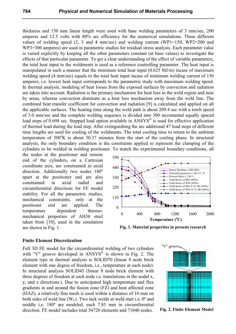
In the present analysis, to represent the heat generated by the torch in GTAW, a heat source model
was developed and implemented by author written subroutines. For the heat input distribution to the
weldments, the most widely acceptable double ellipsoidal heat source model, presented by Goldak
et al. [11] is used to present the heat generated by the welding torch. The heat source is assumed to
move through volume and calculated heat is applied to elements as volumetric heat generation so
that the elements lying on the surface can be used for modeling of surface heat convection The
variations due to curvature of the cylinders are not taken into account. The model gives the
Gaussian distribution for circumferential welding and has excellent features of power and density
distribution control in the weld pool and HAZ. The heat source model n Fig. 3 along with heat
source parameters used in present analysis are shown in Table 1.
Table 1: Heat Source Parameters
(Fixed for all studies)
Parameter Value
Length of front ellipsoidal , a1 [mm] 5
Length of front ellipsoidal , a2 [mm] 15
Width of heat source , b [mm] 10
Depth of heat source, c [mm] 2.5
Fraction of heat in front ellipsoidal, ff 1.25
Fraction of heat in front ellipsoidal, fr 0.75
Experimental Validation
In order to validate the simulation results, GTA welding experiments on thin-walled cylinders with
base welding process parameters were conducted.
Commercially available low carbon steel with
slight variations in chemical composition from
the material model used in the simulation is
utilized. Similar approximations were made in the
past by [12] with reasonable comparative
measured and predicted results. For thermal
model validation, sample from the welded
cylinders at a section 150° from the weld start
position was ground, etched, polished and the
width of the FZ and HAZ was revealed at
different locations through the thickness. A
quantitative comparison of measured and
predicted FZ and HAZ values are shown in Fig.
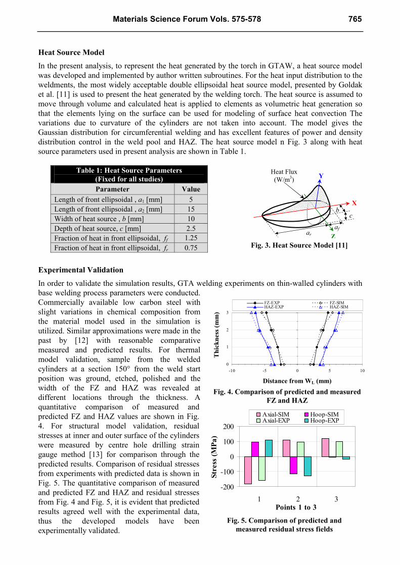
4. For structural model validation, residual
stresses at inner and outer surface of the cylinders
were measured by centre hole drilling strain
gauge method [13] for comparison through the
predicted results. Comparison of residual stresses
from experiments with predicted data is shown in
Fig. 5. The quantitative comparison of measured
and predicted FZ and HAZ and residual stresses
from Fig. 4 and Fig. 5, it is evident that predicted
results agreed well with the experimental data,
thus the developed models have been
experimentally validated.
Fig. 4. Comparison of predicted and measured
FZ and HAZ
0
1
2
3
-10 -5 0 5 10
Distance from WL
Thickness (mm)
FZ-EXP FZ-SIMHAZ-EXP HAZ-SIM
Distance from WL (mm)
Thickness (m
m)
Fig. 5. Comparison of predicted and
measured residual stress fields
-200
-100
0
100
200
1 2 3Points 1 to 3
Stress (MPa)
Axial-SIM Hoop-SIMAxial-EXP Hoop-EXP
Fig. 3. Heat Source Model [11]
Materials Science Forum Vols. 575-578 765
Results and Discussion
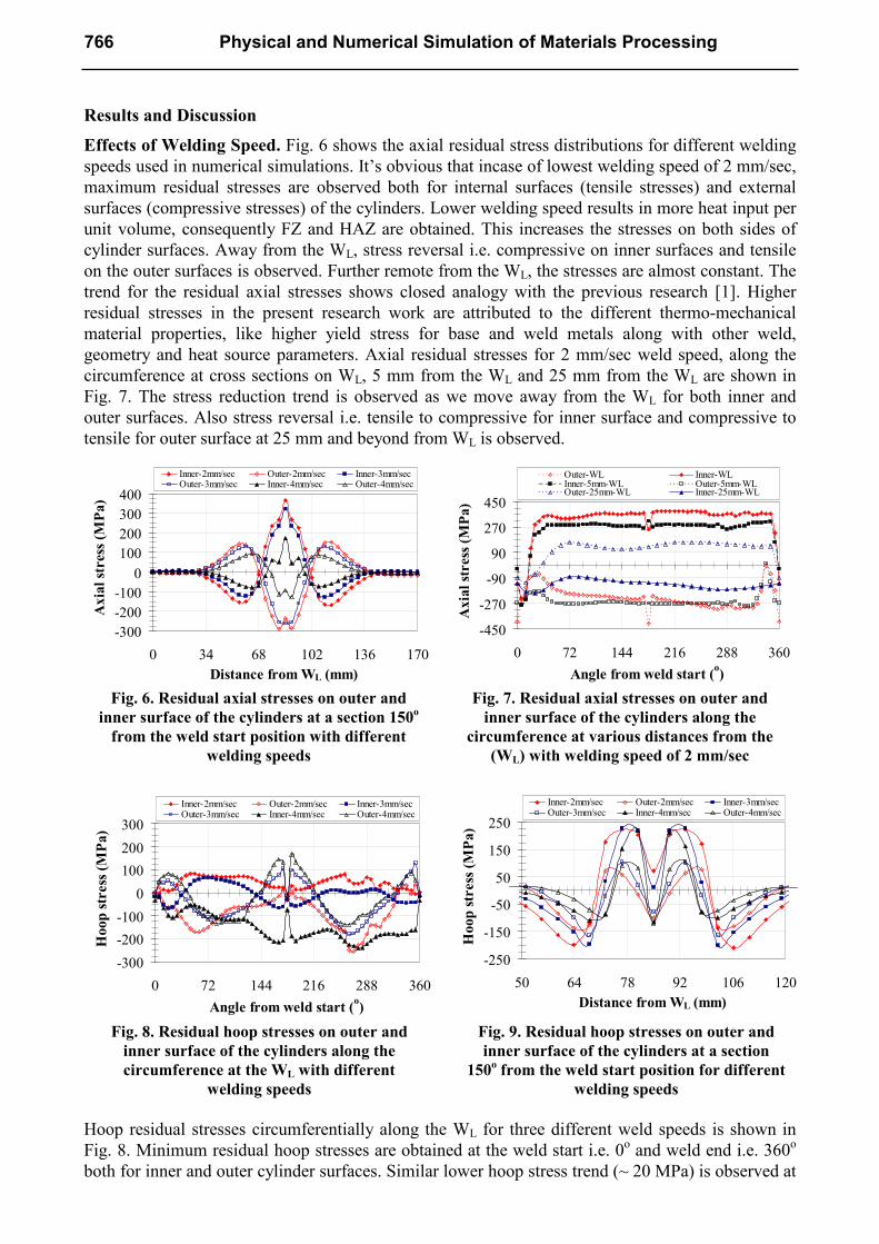
Effects of Welding Speed. Fig. 6 shows the axial residual stress distributions for different welding
speeds used in numerical simulations. It’s obvious that incase of lowest welding speed of 2 mm/sec,
maximum residual stresses are observed both for internal surfaces (tensile stresses) and external
surfaces (compressive stresses) of the cylinders. Lower welding speed results in more heat input per
unit volume, consequently FZ and HAZ are obtained. This increases the stresses on both sides of
cylinder surfaces. Away from the WL, stress reversal i.e. compressive on inner surfaces and tensile
on the outer surfaces is observed. Further remote from the WL, the stresses are almost constant. The
trend for the residual axial stresses shows closed analogy with the previous research [1]. Higher
residual stresses in the present research work are attributed to the different thermo-mechanical
material properties, like higher yield stress for base and weld metals along with other weld,
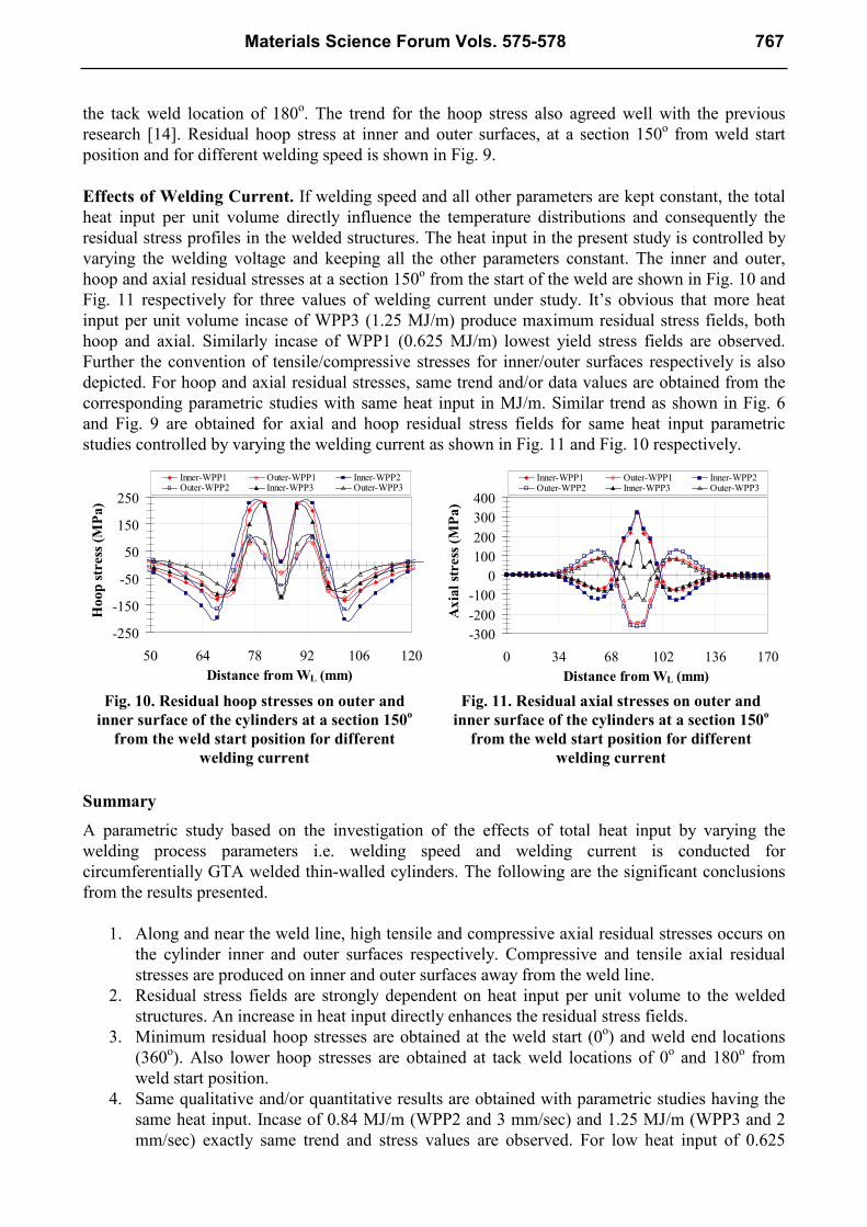
geometry and heat source parameters. Axial residual stresses for 2 mm/sec weld speed, along the
circumference at cross sections on WL, 5 mm from the WL and 25 mm from the WL are shown in
Fig. 7. The stress reduction trend is observed as we move away from the WL for both inner and
outer surfaces. Also stress reversal i.e. tensile to compressive for inner surface and compressive to
tensile for outer surface at 25 mm and beyond from WL is observed.
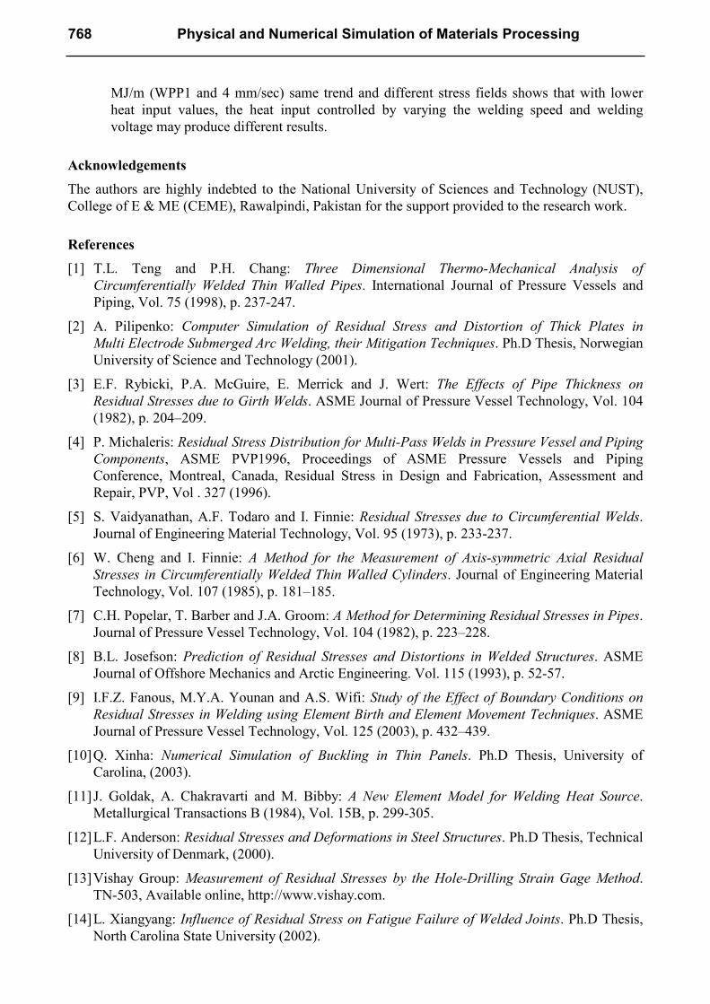
Hoop residual stresses circumferentially along the WL for three different weld speeds is shown in
Fig. 8. Minimum residual hoop stresses are obtained at the weld start i.e. 0o and weld end i.e. 360
o
both for inner and outer cylinder surfaces. Similar lower hoop stress trend (~ 20 MPa) is observed at
Fig. 6. Residual axial stresses on outer and
inner surface of the cylinders at a section 150o
from the weld start position with different
welding speeds
-300
-200
-100
0
100
200
300
400
0 34 68 102 136 170
Distance from WL (mm)
Axial stress (MPa)
Inner-2mm/sec Outer-2mm/sec Inner-3mm/secOuter-3mm/sec Inner-4mm/sec Outer-4mm/sec
Fig. 7. Residual axial stresses on outer and
inner surface of the cylinders along the
circumference at various distances from the
(WL) with welding speed of 2 mm/sec
-450
-270
-90
90
270
450
0 72 144 216 288 360
Angle from weld start (o)
Axial stress (MPa)
Outer-WL Inner-WLInner-5mm-WL Outer-5mm-WLOuter-25mm-WL Inner-25mm-WL
Fig. 9. Residual hoop stresses on outer and
inner surface of the cylinders at a section
150o from the weld start position for different
welding speeds
-250
-150
-50
50
150
250
50 64 78 92 106 120
Distance from WL (mm)
Hoop stress (MPa)
Inner-2mm/sec Outer-2mm/sec Inner-3mm/secOuter-3mm/sec Inner-4mm/sec Outer-4mm/sec
Fig. 8. Residual hoop stresses on outer and
inner surface of the cylinders along the
circumference at the WL with different
welding speeds
-300
-200
-100
0
100
200
300
0 72 144 216 288 360
Angle from weld start (o)
Hoop stress (MPa)
Inner-2mm/sec Outer-2mm/sec Inner-3mm/secOuter-3mm/sec Inner-4mm/sec Outer-4mm/sec
766 Physical and Numerical Simulation of Materials Processing
the tack weld location of 180o. The trend for the hoop stress also agreed well with the previous
research [14]. Residual hoop stress at inner and outer surfaces, at a section 150o from weld start
position and for different welding speed is shown in Fig. 9.
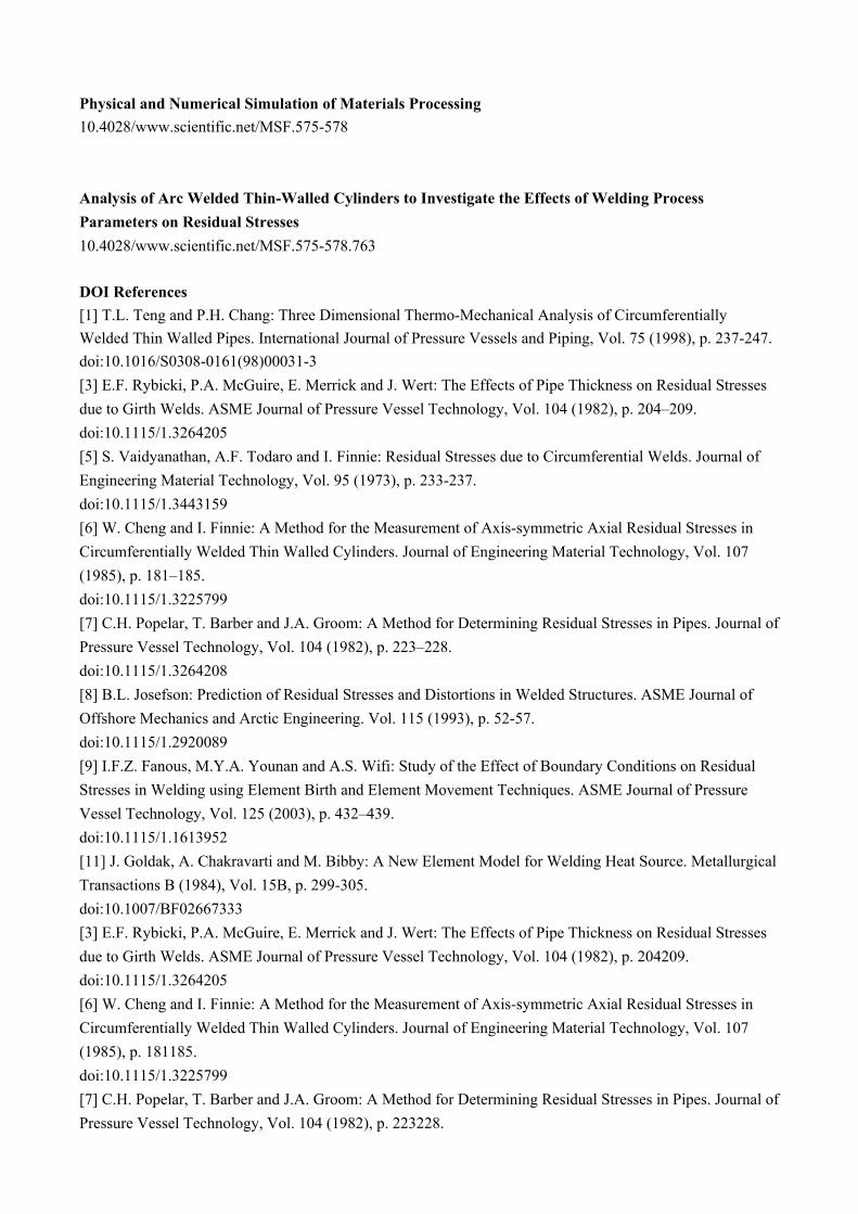
Effects of Welding Current. If welding speed and all other parameters are kept constant, the total
heat input per unit volume directly influence the temperature distributions and consequently the
residual stress profiles in the welded structures. The heat input in the present study is controlled by
varying the welding voltage and keeping all the other parameters constant. The inner and outer,
hoop and axial residual stresses at a section 150o from the start of the weld are shown in Fig. 10 and
Fig. 11 respectively for three values of welding current under study. It’s obvious that more heat
input per unit volume incase of WPP3 (1.25 MJ/m) produce maximum residual stress fields, both
hoop and axial. Similarly incase of WPP1 (0.625 MJ/m) lowest yield stress fields are observed.
Further the convention of tensile/compressive stresses for inner/outer surfaces respectively is also
depicted. For hoop and axial residual stresses, same trend and/or data values are obtained from the
corresponding parametric studies with same heat input in MJ/m. Similar trend as shown in Fig. 6
and Fig. 9 are obtained for axial and hoop residual stress fields for same heat input parametric
studies controlled by varying the welding current as shown in Fig. 11 and Fig. 10 respectively.
Summary
A parametric study based on the investigation of the effects of total heat input by varying the
welding process parameters i.e. welding speed and welding current is conducted for
circumferentially GTA welded thin-walled cylinders. The following are the significant conclusions
from the results presented.
1. Along and near the weld line, high tensile and compressive axial residual stresses occurs on
the cylinder inner and outer surfaces respectively. Compressive and tensile axial residual
stresses are produced on inner and outer surfaces away from the weld line.
2. Residual stress fields are strongly dependent on heat input per unit volume to the welded
structures. An increase in heat input directly enhances the residual stress fields.
3. Minimum residual hoop stresses are obtained at the weld start (0o) and weld end locations
(360o). Also lower hoop stresses are obtained at tack weld locations of 0
o and 180
o from
weld start position.
4. Same qualitative and/or quantitative results are obtained with parametric studies having the
same heat input. Incase of 0.84 MJ/m (WPP2 and 3 mm/sec) and 1.25 MJ/m (WPP3 and 2
mm/sec) exactly same trend and stress values are observed. For low heat input of 0.625
Fig. 10. Residual hoop stresses on outer and
inner surface of the cylinders at a section 150o
from the weld start position for different
welding current
-250
-150
-50
50
150
250
50 64 78 92 106 120
Distance from WL (mm)
Hoop stress (MPa)
Inner-WPP1 Outer-WPP1 Inner-WPP2Outer-WPP2 Inner-WPP3 Outer-WPP3
Fig. 11. Residual axial stresses on outer and
inner surface of the cylinders at a section 150o
from the weld start position for different
welding current
-300
-200
-100
0
100
200
300
400
0 34 68 102 136 170
Distance from WL (mm)
Axial stress (MPa)
Inner-WPP1 Outer-WPP1 Inner-WPP2Outer-WPP2 Inner-WPP3 Outer-WPP3
Materials Science Forum Vols. 575-578 767
MJ/m (WPP1 and 4 mm/sec) same trend and different stress fields shows that with lower
heat input values, the heat input controlled by varying the welding speed and welding
voltage may produce different results.
Acknowledgements
The authors are highly indebted to the National University of Sciences and Technology (NUST),
College of E & ME (CEME), Rawalpindi, Pakistan for the support provided to the research work.
References
[1] T.L. Teng and P.H. Chang: Three Dimensional Thermo-Mechanical Analysis of
Circumferentially Welded Thin Walled Pipes. International Journal of Pressure Vessels and
Piping, Vol. 75 (1998), p. 237-247.
[2] A. Pilipenko: Computer Simulation of Residual Stress and Distortion of Thick Plates in
Multi Electrode Submerged Arc Welding, their Mitigation Techniques. Ph.D Thesis, Norwegian
University of Science and Technology (2001).
[3] E.F. Rybicki, P.A. McGuire, E. Merrick and J. Wert: The Effects of Pipe Thickness on
Residual Stresses due to Girth Welds. ASME Journal of Pressure Vessel Technology, Vol. 104
(1982), p. 204–209.
[4] P. Michaleris: Residual Stress Distribution for Multi-Pass Welds in Pressure Vessel and Piping
Components, ASME PVP1996, Proceedings of ASME Pressure Vessels and Piping
Conference, Montreal, Canada, Residual Stress in Design and Fabrication, Assessment and
Repair, PVP, Vol . 327 (1996).
[5] S. Vaidyanathan, A.F. Todaro and I. Finnie: Residual Stresses due to Circumferential Welds.
Journal of Engineering Material Technology, Vol. 95 (1973), p. 233-237.
[6] W. Cheng and I. Finnie: A Method for the Measurement of Axis-symmetric Axial Residual
Stresses in Circumferentially Welded Thin Walled Cylinders. Journal of Engineering Material
Technology, Vol. 107 (1985), p. 181–185.
[7] C.H. Popelar, T. Barber and J.A. Groom: A Method for Determining Residual Stresses in Pipes.
Journal of Pressure Vessel Technology, Vol. 104 (1982), p. 223–228.
[8] B.L. Josefson: Prediction of Residual Stresses and Distortions in Welded Structures. ASME
Journal of Offshore Mechanics and Arctic Engineering. Vol. 115 (1993), p. 52-57.
[9] I.F.Z. Fanous, M.Y.A. Younan and A.S. Wifi: Study of the Effect of Boundary Conditions on
Residual Stresses in Welding using Element Birth and Element Movement Techniques. ASME
Journal of Pressure Vessel Technology, Vol. 125 (2003), p. 432–439.
[10] Q. Xinha: Numerical Simulation of Buckling in Thin Panels. Ph.D Thesis, University of
Carolina, (2003).
[11] J. Goldak, A. Chakravarti and M. Bibby: A New Element Model for Welding Heat Source.
Metallurgical Transactions B (1984), Vol. 15B, p. 299-305.
[12] L.F. Anderson: Residual Stresses and Deformations in Steel Structures. Ph.D Thesis, Technical
University of Denmark, (2000).
[13] Vishay Group: Measurement of Residual Stresses by the Hole-Drilling Strain Gage Method.
TN-503, Available online, http://www.vishay.com.
[14] L. Xiangyang: Influence of Residual Stress on Fatigue Failure of Welded Joints. Ph.D Thesis,
North Carolina State University (2002).
768 Physical and Numerical Simulation of Materials Processing
Physical and Numerical Simulation of Materials Processing 10.4028/www.scientific.net/MSF.575-578 Analysis of Arc Welded Thin-Walled Cylinders to Investigate the Effects of Welding Process
Parameters on Residual Stresses 10.4028/www.scientific.net/MSF.575-578.763
DOI References
[1] T.L. Teng and P.H. Chang: Three Dimensional Thermo-Mechanical Analysis of Circumferentially
Welded Thin Walled Pipes. International Journal of Pressure Vessels and Piping, Vol. 75 (1998), p. 237-247.
doi:10.1016/S0308-0161(98)00031-3 [3] E.F. Rybicki, P.A. McGuire, E. Merrick and J. Wert: The Effects of Pipe Thickness on Residual Stresses
due to Girth Welds. ASME Journal of Pressure Vessel Technology, Vol. 104 (1982), p. 204–209.
doi:10.1115/1.3264205 [5] S. Vaidyanathan, A.F. Todaro and I. Finnie: Residual Stresses due to Circumferential Welds. Journal of
Engineering Material Technology, Vol. 95 (1973), p. 233-237.
doi:10.1115/1.3443159 [6] W. Cheng and I. Finnie: A Method for the Measurement of Axis-symmetric Axial Residual Stresses in
Circumferentially Welded Thin Walled Cylinders. Journal of Engineering Material Technology, Vol. 107
(1985), p. 181–185.
doi:10.1115/1.3225799 [7] C.H. Popelar, T. Barber and J.A. Groom: A Method for Determining Residual Stresses in Pipes. Journal of
Pressure Vessel Technology, Vol. 104 (1982), p. 223–228.
doi:10.1115/1.3264208 [8] B.L. Josefson: Prediction of Residual Stresses and Distortions in Welded Structures. ASME Journal of
Offshore Mechanics and Arctic Engineering. Vol. 115 (1993), p. 52-57.
doi:10.1115/1.2920089 [9] I.F.Z. Fanous, M.Y.A. Younan and A.S. Wifi: Study of the Effect of Boundary Conditions on Residual
Stresses in Welding using Element Birth and Element Movement Techniques. ASME Journal of Pressure
Vessel Technology, Vol. 125 (2003), p. 432–439.
doi:10.1115/1.1613952 [11] J. Goldak, A. Chakravarti and M. Bibby: A New Element Model for Welding Heat Source. Metallurgical
Transactions B (1984), Vol. 15B, p. 299-305.
doi:10.1007/BF02667333 [3] E.F. Rybicki, P.A. McGuire, E. Merrick and J. Wert: The Effects of Pipe Thickness on Residual Stresses
due to Girth Welds. ASME Journal of Pressure Vessel Technology, Vol. 104 (1982), p. 204209.
doi:10.1115/1.3264205 [6] W. Cheng and I. Finnie: A Method for the Measurement of Axis-symmetric Axial Residual Stresses in
Circumferentially Welded Thin Walled Cylinders. Journal of Engineering Material Technology, Vol. 107
(1985), p. 181185.
doi:10.1115/1.3225799 [7] C.H. Popelar, T. Barber and J.A. Groom: A Method for Determining Residual Stresses in Pipes. Journal of
Pressure Vessel Technology, Vol. 104 (1982), p. 223228.

doi:10.1115/1.3264208 [9] I.F.Z. Fanous, M.Y.A. Younan and A.S. Wifi: Study of the Effect of Boundary Conditions on Residual
Stresses in Welding using Element Birth and Element Movement Techniques. ASME Journal of Pressure
Vessel Technology, Vol. 125 (2003), p. 432439.
doi:10.1115/1.1613952