Embed Size (px)
Citation preview

International Journal of
STRUCTURAT STABILITYAND DYNAMICS
Volume 7. Number I . March 2007
Size Effect of Welded Thin-WalledTubular Joints
F. R. N{ashiri, X.-L. Zhao, NI. A. Hirt and A. Nussbaumer
l l r
llS World Scientificltl-
NEWJERSEY . LONDON . SINGAPORE . BEIJING . SHANGHAI . HONGKONG . TAIPEI . CHENNAI
International Journal of Structural Stability and DynamicsVol. 7, No. 1 (2007) rOI I27@ World Scientific Publishing Company
SIZE EFFECT OF \MELDED THIN-WALLED TUBULAR JOINTS
FIDELIS RUTENDO MASHIRI
SchooL oJ Engineerzng, Unzuersi.ty of Tasmani,aPriuate Bag 65, Hobart, TAS 7001, Australi.a
F'id,el'is. M ashi,r,i@ utas. edu. au
XIAO-LING ZHAO
Department of Ciail Engineeri,ng, Monash UniuersztyWell'ington Rd, CLayton, VIC. 38A0, Australia
MANFRED A. HIRT and ALAIN NUSSBAUMER
Department of Ciuil Eng'ineeri,ngEcole Polytechnzque Fed,erale d,e Lausanne
C H- 1 0 1 5, Lausanne, Suitzerland,
Received 17 February 2006Accepted 5 December 2006
This paper cla,rifies the terminologies used to describe the size effect on fatigue behaviorof welded joints. It summarizes the existing research on size effect in the perspectiveof newly defined terminologies. It identifies knowledge gaps in designing tubular jointsusing the hot spot stress method, i.e. thin-walled tubular joints with wall thickness lessthan 4 mm and thick-walled tubular joints with wall thickness larger than 50 mm, ordiameter to thickness ratio less than 24. It is the thin-walled tubular joints that areaddressed in this paper. It is found that thin-walled tube-plate T-joints do not followthe conventional trend: the thinner the section is, the higher the fatigue life. It is alsofound that simple extrapolation of existing fatigue design curves may result in unsafedesign of thin-walled tube-tube T-joints. The effect of chord stiffness on fatigue behaviorof thin-walled tubular T-joints is also discussed
Keyuords: Size effect; thickness effect; welded joints; plate; tube; weld defects; fatigue.
1. Introduction
Fatigue life of welded joints depends on many parameters. Some of the parameterswhich influence fatigue life are among others, wall thickness of plates or tubes, weldshape and size, residual stress field and non-dimensional parameters of a connection.The wall thickness is sometimes regarded âs the most important parameter whencomparing the relative fatigue life of two welded joints, hence the term "thicknesseffect" is widely used in the literaturel-5 and the term "thickness correction factor"is used in various standards.6 8 Other terms that are also found in the literatureare ((size
effect", "scaling effect" and "geometrical effect't.5,9,10 In addition to theaforementioned parameters, fatigue life of welded connections is also influenced bypost weld treatment11,12 and the environment condition.13-15
101

lO2 F. R. Mashi,ri, et al.
This paper attempts to clarif,i the terminologies. It briefly summarizes some ofthe previous research dealing with size effect. The newly defined terminologies areused to examine each research. The size effect in existing design recommendationsfor some tubular joints is summarized in the format of both classification methodand hot spot stress method. The existing design recommendation based on hot spotstress metho616'17 6o"r not cover tubular joints with wall thickness less than 4mmor larger than 50 mm or with 21 value less than 24. The tubular joints with t < 4 mrnis called thin-walled tubuiar joints while those with I > 50 mm or 21 I 24 arecalled thick-walled tubular joints in this paper. Reports on the thick-walled tubularjoints can be found in Schumacherls and Schumacher et al.s Only the thin-walledtubular T-joints are addressed in this paper. The research in thin-walled tubularjoints has been necessitated by the increased availabiiity of thin cold-formed tubesmade from high-strength steel. This has Ied to an increased use of welded thin-walled (l < 4 mm) tubes in the manufacture of structural systems subjected tocyclic ioading such as agricultural and road transport industry equipment. Thehollow sections are welded to form structural support systems in trucks, trailers,haymakers, swing-ploughs, linkage graders, traffic sign supports and lighting poles.These structural systems are subjected to cyclic ioading in service.The conventionaltrend in fatigue ,5-1y' curve will be verified for such thin-walled tube-plate T-joints.The suitability of simply extrapolating existing fatigue design ,9-l/ curves for thin-walled tube tube joints will be checked. Discussions are also made on the effect ofchord stiffness on the fatigue behavior of thin-walled tubular T-joints.
2. Terminologies
Different terminologies were used in the literature when comparing the fatiguebehavior of welded joints. This section aims to clarify the concept and define thenew terminologies.
Fatigue life of welded joints may be affected by connection size and improvementtechnoiogy. The fatigue life of welded connections can therefore be classified asinfluenced by two main components, i.e. size effect and improvement effect. Thesize effect inciudes statistical size effect, technological size e1lect and geometrical
size effect. These three effects can be represented or studied quantitatively usinga scaling effect when comparing the fatigue behavicir of two welded joints. Detailsare explained below.
2.1. Size effect
2.I.1. Stati,st'ical s'ize effect
Size effect in fatigue may be interpreted using the so-called statistical effect whichstems from the fact that fatigue is a weakest link process, nucleating at the locationwhere stresses, geometry, defects and material properties combine to form optimumconditions for fatigue crack initiation and growth. Increasing the size of a specimenwill statistically produce locations that are more vulnerable to fatigue failures.le

Si,ze Effect of Weld,ed Thi,n-Walled, Tttbular Jo'ints 103
Ôrjasaeter et al.zo termed the statistical effect, the volume effect, and interpreted itas a correlation between the volume of highly stressed material and fatigue strength.A possibility to consider this effect is based on the weakest link theory proposedby Weibull2l and Savaidis et a1.22 Fatigue tests of welded joints are influenced bythe initiation and growth of small ellipsoidal cracks from the weld toe. The lengthof the weld toe from which the cracks initiate is therefore an influencing factor forfatigue strength since a larger length results in more likelihood of initiation andfailure of the welded ioint.23
2.I.2. Technological s'ize effect
Technological size effect results from differences in production parameters. Forexample, due to differences in rolling reduction ratios, the mechanical propertiesdiminish with increasing plate thickness. This effect can be neglected if mechan!cal properties are essentially the same for different thicknesses. Technological sizeeffect can be considered to occur as a result of varying residual stresses caused bywelding in different plate thicknesses. Technological size effect can also be under-stood in terms of geometrical size effect at the mesoscale level, which originatesfrom incomplete scaling. When all dimensions are scaled up or down equally, thematerial properties such as grain size, flaw dimensions and mechanical propertiesdo not change.23
2.L.3. Geometrical si,ze effect (at the mesoscale leuel)
A model can be used for explaining the thickness effect in rvelded joints wherefatigue cracks initiate from the weld toes.1,13 In this model the foilowing assump-tions are adopted: (i) welded joints of the same type in various plate thicknesses aregeometrically similar. This is typical of load-carrying welded joints, and (ii) initialconditions of fatigue crack growth are independent of plate thickness. This meansthat the initial cracks in welds of different thicknesses are of the same magnitude.Therefore the stress distribution across the ioad-carrying plates in the crack growthplane are geometrically similar, leading to a steeper stress gradient in the thinnerjoint, according to assumption (i). Using assumption (ii), the initial crack in thethinner plate will experience a smaller stress than the initial crack of the sameIength in the thicker plate. This results in a smaller initial crack growth in thethinner joint.a'1e
2.2. Scaling effect
This paper introduces a new concept called "scaiing effect". The scaling effectincludes complete proportional scaling, practical proportional scaling and non-proportional scaling. Complete proportional scaling is defined as the case where allfactors affecting fatigue are scaled proportionally, whatever their origin (statistical.
technological or geometrical). Practical proportional scaling is defined as the casewhere only important factors are scaied proportionally. Non-proportional scaling

104 F. R. Mash'iri et aL.
is defined as the case where some important factors are not scaled proportionally.The more the parameters affecting the fatigue of a connection, the less chance toachieve a complete proportional scaling. In fact only very simple plated connectiontypes (e.g. plate with transverse attachments) may achieve complete proportionalscaling. For tubular joints, practical proportional scaling may be achieved if theimportant non-dimensional parameters (p, r,21) are scaled proportionally. Whenthickness is the only parameter needed to describe the relative fatigue life of twojoints, we call this case "complete" thickness effect. It only could happen under thecondition of complete proportion of two joints. It is only possible for verv simplervelded joints such as transverse attachments. When thickness is one of the param-eters needed to describe the relative fatigue life of two joints, we call the influencedue to thickness "partial" thickness effect. When the influence of other parametersis insignificant, the "partial" thickness effect may be approximated as the "com-plete" thickness effect. In the expression describing the relative fatigue strength,there are two possible reference cases. When the reference thickness is the smallerone, it is called thickness correction factor, and when it is the larger one. it is calledthinness correction factor.
The flowchart in Fig. 1 shows the two categories that can influence fatigue life.The flowchart shows in detail the different concepts that form part of the size andimprovement effects.
2.3. frnprooement effect
The improvement effect results from the enhancement in geometry and residualstress distribution within the welded connection due to post-weld treatments. Theimprovement of geometry in welded connections can result from processes such asweld toe grinding and TIG dressing. These processes cause a decrease in stress
Fig. 1. Size and improvement effects and their corresponding concepts.
t,,",,pr..il'.p*;" I l- ""]I-d;'.--"--il I trv.-rilrJ-l
Completc th.ickness elbctor
Piltial thickncss effæt

Si.ze Effect of Welded Thin-Walled Tubular Jo'ints 105
concentration due to the improved geometry at the toes of the weld, a result of asmoother and hence gradual transition between two welded plates or sections. Theresidual stress at weld toes can also be improved through processes such as hammeror shot peening which cause a reduction in tensile residual stresses or a changein residual stress at the locations of interest from tension to compression. Moredetails can be found in Haagensen and N4addox12 as well as Walbridge et al.za Theimprovement effect thus have different degrees of influences on all the size effects(statistical, technological and geometricai).
3. Existing Research on Size Effect
Apart from the researchers mentioned in the previous sections, numerousresearchers have investigated the size effect phenomenon from as early as the 1950sto this day. This research has led to a better understanding of the influence of plate
andfor tube-wall thickness on fatigue strength of welded connections. In his 1989review, Gurney2 pointed out that thickness effect could be demonstrated using bothfracture mechanics theory and experimental work. This had led to the introductionof a thickness correction factor in the revised version of the UK Department ofEnergy Guidance Notes in 1984. Gurney2 also noted that much earlier than theintroduction of the thickness effect on fatigue of welded connections, Phillips andHeywood2s had demonstrated the size dependence of fatigue strength of unweldedspecimens. Gurney2 also pointed out that it had long been known that plate thick-ness was likely to be a relevant variable for fatigue strength under bending stresses,because the stress gradient through the thinner specimen would be steeper andtherefore less damaging than that in thicker specimens. Gurney26 showed withthe use of fracture mechanics theory, the fatigue strength of welded joints couldbe affected by plate thickness even when they were subjected to axial loading.Gurney2T pointed out on the basis of fracture mechanics analysis and experimental
evidence that the effect of plate thickness on fatigue strength could be significant.Other researchers have also studied the behavior of welded plate, tubular and
tube-plate joints with different wall thicknesses. This research has either strength-
ened the concept of thickness effect or culminated in the introduction of thickness
correction factors in various standards around the world. In the ma.jority of the
research on plated specimens, the main plate and transverse plates are usually ofequal thickness.
When thickness effect is studied using main plate and transverse plates of equal
thickness, the category of scaling can be referred to as practical proportional scal-ing. This is because the most important parameter influencing thickness effect.is whether wall thickness of the plate is scaled proportionally. However, although
the thickness is scaled proportionally in plated joints, other parameters such asweld size, though normally increasing with increasing thickness to cope with anincrease in applied design load, may not be proportionally scaled, in particular innon-load carrying welded connections. Other parameters that also vary but not

@ûûaoo
€OYS9Ya.À ,Y L . -
-V!ox
(n(d
ôôdE drOLboQkbnf x. : -H x.=!ùQ<d.docd
ÀÀù 0"0.r i
9!M
f x. :FPd
tli tli t/l
onN+
n
000md
IÔÉ
NT
û@
9ÈU
(dOcd
Ê.0.ù
Nn
NÊ
.?j o .= e9.
€s3 E ÉE e"t^ eE: çr . - ,
^ - . ! Niç f , . l -o .9
iË: Hq ; EË 4eË ;€Hi l s€-Ë=-
j .9çÈ -Fg:39
; :J; ;ËEë.ï+:Ë#> g5g€à! !EE; ëùËEEË.:â:"E EE:rEeH $E=ry gE;+; ;EÉ*ao,ï t ;xÈ ; ; rE s6EËFERT;âg ETÈâÈ; *=TE7,
Ë;s e, ;s És g-Eg sÈ g 3E É €**5, , € e
t r7 9i : cd
g- bùepH 'a:7
x F c l i ++o ! 6 Y'F+O'6 O âô
!
o.-
ÇsËcr( , à
o
r)O
o
O
ûtro
F@
d
È
N
m
N(oæÊf-
À -x
^-/
F
3{. - €È$
îàË!
106 F. R. Mashiri et al.
=di
B.= X Tç+ a X
r)^ Lr- l
ob!
9û
B'acô
-q.Yi=lXi ' ;< -y _6 l
@
a
<=\n
.cP
aû
90
.=l^
bo
d
-l
o
F
a
.9
.9
N
@
!
FE(n
..i
-

Size Effect of Welded Thin-Walletl Tubular Joints 107
q
CAlt
ri
u.bo
b,0
€
ix:v
CA\
i l3cDq
'- t l
.9 h^ '
O -\
Y;; . -
Ë Ë,f07l lrcÉ,^
P X<'
I9e6 âU
s!,
l l -
ooh
2ç4É.
-- . -5ÊN r-
oaoÊÊ@
ÈÈs
; ixo yô62tùZ
- 9-Ë.. F É5c<.g ;ÈP È =:--t .=!E É .s! . i
-F- : ' _E;
t x x ' - v a x Y L: :
- - { = = 4-a B
P. ëEgbæQ qd,a; t ;ç:ÈbË;=#=Ë EËbà3E ËË;]Sf €Et8gg €err
aûûaûQ
eQY€OYL.n.v ! .É .v
ô Lr- t ^
Lr , l
Èoo!bo
0.Ê.d
G?Êo -o.9:9.9H9f x.= f x. :xt i= x: i=
F"Àù ÀÀù
F
-csooÈ
6B
^âr 3 .E
E EËO È!PEEeFH* d Ê ? à
:9EsËÉÉjg]5.->!
'^ -
a.= '9Xtç.dË+:fËs-ÈË
.oa
;g!O
OÈ
{
X
Nca
f.-
Nq
ool -€€
. -d. iÀ!
QnO!1"
a 2.7 0 C ô! :€ H:o
=dÉ-
ËÈëÇvr-q
l) (n
8-éo.o
;{9 0X
- , : .9-o: !-V!EÈ
@
@
r!=
<=.o!
F
ijit1
b0
I
F]
o
o
F
a
a
,9
\JU
a\
.i
r':
-

@@ûaaû
J9Y,9YJOX!.r .v L.È,v ! . i_v
û@aaoo
+QY€AY! . - ,9 ! . i ,q
ddd
lboLbOLM
rô.<rô.-rô.<
z0.ù za-ù, z) .ù,
(Éd
ôô(dE =albo!bô
Ê"Àd6 za.ù
@
.?F
@
F
À
e9:a ÈÊàN. ço.
ôA
Â$ J*UOAA
T
^\€I ùZ
e: vfr ;.= 9 .=--rJO
9I 9 ! ;Ng*â-
xiYx<9v:; i ; t9* v,* ,* FcÉ3 ÉÈo-S
; ë È ë gâ
oo
+@
qN
ô ! : -o
N N t i
f
É:
'Â d! I: . -
-
iq X:. IE+ <-à 5
a . .:1 -"2; Fv a
v 6 ._.r
q =x.=
P. F>X
NO
b0ù
€-
d^
aJâ
Êt>
{q Ë
3' i " o 9i t Ê3€g= o 6
(a
æ
àz
: yx5d9
5Ê PE':c i o^ d Âc- ih cEi ' i -1--' -Ës ' - ; 'qE:* l l '= 'd l li3È €eEËÈ=c €9c.EET_ ÉEËÉîËH EËÉ:EI; ËB€Egi€ r- f f iEslEJ E[É;gÈË E;E
9s
E i l 'E K 5 !
- I E- 'a l l
- ' i - .ga
= 5 É o c- Ë I c t roo= s: g== E Ë.c 9{: c.6 ! 5I ,o _ i iVtr c-AiÛs ; '=8,
-ç 'açÉPÈç ;9s. '
E= >Ë:SE-Ë toËÈ
I
obo
. - o o
€ i,o.ts bô.Ë
ôUF9F
O ^!>- É -
-O€À€À
;ir . : - t . :d
108 F. R. Mashiri et al.
=dl-s_: I
-Ê! 9:
\ )a
3'a9, I!QLY
- :.Y i c ' f i ËF!.9.éF-V€EH
û
<E\d
oi i
AO
ôF
b0
E
F]
o
F
@a
,ea?
a
b
'iO
F
Si,ze Effect of Welded Thin-Walled. Tubular Joi,nts 109
i€ iL
^L'v
o âE È! l := !! .ç o -Ve-* Iyl û:LgO
*oÊë o <
-^-Ye,ô v oXi. : E Àô l l > Æè: .qo =
!<t>Ê
) oE o I9-> - .q @o!\
n !è -
7, :d u> :F*: Ëd
9àv ËXroi f i
^vl- ! ' l ;:
-=
( o *"
- io"r :R 4b
Ç 6 , È" b! È.cI o | =o(^t 'd -- a , , =
E E: iË ! àr À X weùÉ=^
Y " OV
-ËÈ I+€3
i ln èËrÉgË: Evot= r . - =- iar
d c è u lJ € ' l! Y =Ê O_:dâlt :og-c iè -à
| a E! i E: : evr. : -* J ' : -o o>5: .É' -
O' !Ë ^ , Y @
€'- n.= t 6 ËÊ(:>..9. : h A4 :" T,r H f t in." ; at!È I 5uà*
' Q a r , b! I .J
s:9. , F9 ô -j .gË S F qiGo"
is ' , i . r i i r i-9S9=t; . iu,-n, i "E'oE.Y---nàt-
EÊ:!Êeee= | I " 'q- â
o{. i Ë Ë E U È=ê = v = . 01 +
r !9-E y 6- "ôi ; : îà.e.P
- ) *= È -
6 - -*q: . - iê! ;
rè P.c U Ë.9.9Y- -*S r7-
ucô! o À'à | I: ï - É-- - ,n
^ ^3l l r* :gùù@.r, q 6. : q!q !4
N - :ÉtYX',2 ' ,
n- a d - ' :9 U;E=:Ë:EE. . : ! . Q . . : . . . .
câ i :4s.En@ô, o - *
O ", .9 - O ro 3 O
RË È-rà=àà
a
FE R
o
. lo
za,
ôzùz
a
!d
o
ç!
çê
aa
O-
iaoo.
-à
EoN
æËL' 6
=o
d
^îi^dn
co ôl
SN
r€E€d r " .
q?7 É ËÈ
;. ; c; . : 1XfrËi-- X<,ô 5 n.= <
j' . i3.^ :
Èx: Ee. ' . ' , ' ,
- f 'F
-
li ;! \-/ .:
o!!Obo
l i i=d!
ç€ a: i
9A
q-
!Qtzl {9 0x.Yir f it -x-Y_o:
-V€rg
<=\n
Àû
ôFr
t
F-l
o
F
o
o.oo
'<3
o
F

110 F. R. Mash'iri et al
proportionâlly are the weld toe conditions such as weld toe radius and the residualstress magnitude due to welding. If the plate thickness, weld size, weld toe radiusand residual stresses are increased proportionally from specimen to specimen, thencomplete proportional scaling is deemed to have occurred. This condition is difficultto achieve in real structures. When the main plate, transverse or longitudinal platethickness, or dimensions are not directly linked to the applied design load, then wehave a case of practical or non-proportionai scaling.
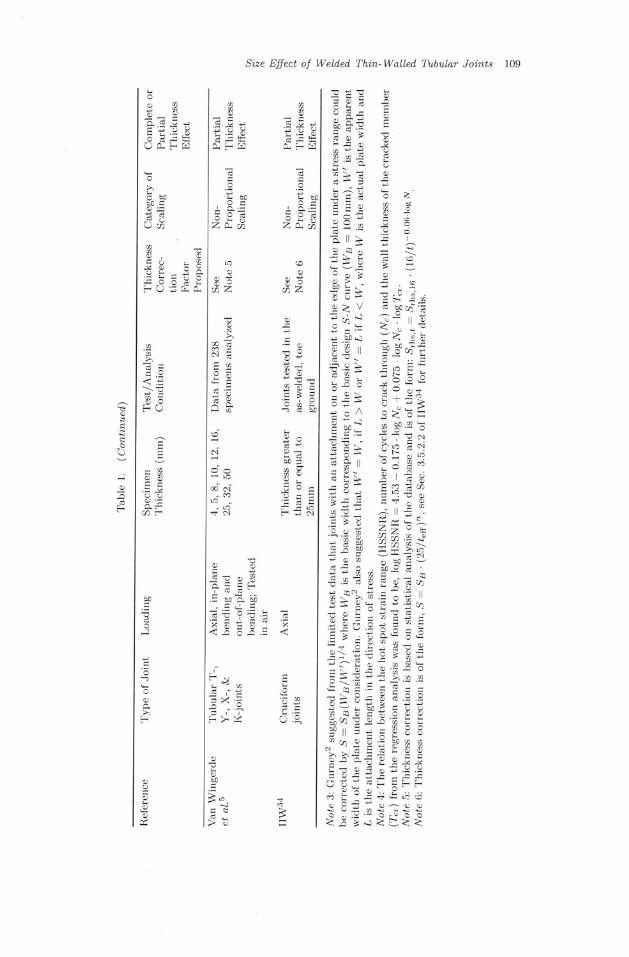
Some of the existing research is summarized in Table 1. The summary showsthe type ofjoints tested, the Ioad type applied and the thicknesses of the plates andtubes tested. The different loads applied confirm the fact that thickness effect isobserved in joints regardless of the type of load to which the connection is subjectedto. The category of scaling used in the studies is shown in Table 1 and the thicknesscorrection factors suggested by some of the researchers are given as footnotes inTable 1.
Table 1 shows that most of the fatigue data that is used in deriving the thicknesscorrection factors for welded plate joints comes from specimens with practical pro-portional scaling. For welded tubular nodal joints, non-proportional scaling mainlyoccurs. Practical proportional scaling and non-proportional scaling results in whatis termed partial thickness effect as shown in Fig. 1. It can be seen that there are nostudies on thin-walled tubular joints (f < 4mm) reported in Table 1, i.e. on rvhatis cailed the thinness effect. This will be the subject of Secs. 5-7 of this paper.
The size effect in welded joints is of the form S : Snftnll)', where,5e is thefatigue strength for a reference plate thickness, tn and,5 is the fatigue strengthfor a plate thickness, t under consideration and n is less than 1.0. Nlore details aregiven in Notes 1 6 of Table 1.
4. Size Effect in Existing Design Recomrnendationsfor Tubular Joints
4.1. Classification method
Various standards around the world have adopted thickness correction factors ordesign ,S-l/ curves that depict thickness effect. Thickness correction factors areobtained by plotting the relative fatigue strength versus the thickness of the failingmember. Gurnev2 obtained the relationship between fatigue strength and thicknessof a member under failure by plotting the reiative fatigue strength normalized toa reference thickness of 32 mm versus the thickness of different plate and tubu-lar joints. Thickness correction factors have been adopted in standards such asthose from the International Institute of tr!'elding,8'16 the British Standards,7,35 theEuropean Standard,36 CIDECT Design Guide No. 817 and Australian Standard,6with however different values for the reference thickness. The thickness correctionfactors can be used to predict the fatigue strength of wall thicknesses other thanthe reference thickness.

Si.ze Effect of Weld.ed Thin-Walled Tubular Joi.nts 111
m
ùÊ9ç
trl 0-
a9,oo9.^.i r - . -
-.Y a o, : Iû '= ût Y
v-;Y
- d X 9.=
xf ! I É
>.xË*:e> 85€ËE
q a9
8s Ë:: $=sE= s4Z1= E;È,
9- P = qpd P
, . ! I ; S g:-=.e ' -nX+ È:*È==^ç>-Ë3: >-!==ts: :g'FËË É'âÈÊ'ÉëÉ=
ooO
a
LOLOh^ à-=i : - : : != a: = u ' i z
.7 16= i Iô i =' = , i :
^ - : . ! - o
Y':e; . 'E ' - ' : o! Yt ;Èâ!" iaÉ: +3=j6. i 3?=t ù,JJVVJUU':A--- . -
Ç' i - , ?-= 4.= + =
, . !3;È 6lÈ;; o.1
^: i ! '== .=oÂ9*ô.;rÉ eÊi
l4:oçH: d!o-: . :EU;. : -a9-ëa
- :4 j a d o
t g! E g i 9: È;7..- .=--
-é-o-+ 9 Y r e o a-=.-ËEcgÊ= ô:=:
qN
A]âi
-ô;
æ
o
-it l
n
ææA] V
no
a?
o
,oo
1?
,o
o€O
@!
û
oâ
a
oO
7f
IIII
II
IIII
IIIII
IIIIIII
IIII
I
III
IIIt , iln
dX
lo
o
;
O
E
Ë
'ô@
EÊ'
E.2o
.=a
.9
oN::
a3F

l l2 F- R. Mashir i e l a l .
Table 3 shows the size effect in tubular connections in some existing standardsin the format of classification method. In the classification method, the fatiguestrength of a constructional detail relates the nominal stress range) due to theapplied member loads, to the number of cycles to failure. The first example inTable 2 (fillet welded circular hollow sections) may be approximated as the case ofcomplete thickness effect. The other two examples in Table 2 may be considered as
"partial thickness effect" because the fatigue life is also influenced by manufacturingmethod for the second example or other non-dimensional parameters for the thirdexample.
4.2. Hot spot stress method
The hot spot stress method relates to the hot spot stress range to the number ofcycles to failure. The fatigue design curves from CIDECT Design Guide No. 817and IIW16 are shown in Fig. 2 with some explanation given in Table 3. It can beseen from Table 3 that the size effect may be considered "partial thickness effect"
because other parameters also influence the fatigue life. It is also interesting to note
that the thickness correction factor in Table 3 also depends on the number of cycles
to failure (N). This stems from the fact that in the low cycle fatigue range, thickness
effect is less pronounced.3T Thickness efect therefore tends to be pronounced as thenumber of cycles to failure increases.
Figure 2 shows the current limitations of the fatigue design curves in IIW16 andCIDECT Design Guide No. 8.17 The limitations in these standards, as shov/n in
Fig. 2, are such that there are no fatigue design curves for thin-walled tubular joints
(r < 4 mm) and for thick-walled joints (f ) 50 mm or 21 .--24). This paper addresses
the size effect of thin-walled tubular joints in the next sections (Secs. 5-7). The size
101.E+04 1.E+05 1.E+06 1.E+07 1.E+08 1.E+09
Fig. 2. Fatigue design curves foridentified.
Number of Cycles, iV
tubular nodal joints in standards16,17 and knowledge gaps
GoE rooaâ

Size Effect of Wetded Thin-Walled. Tubular Joints 113
6Yt.nÈ 6
a Ê ôix Y
---6Oc -bO-O o6 c
û.Y - '7,F'b p Èé*EË
g g eFd . : Éi X
à= èd
:Jd-
@o
,o>cd
=s
.9s
<,ç
- . 1Ë>
=-^rÇ4.=
*e: - i uE4È,.q" '=ç . - - l^^: .Fh:vr
ErË , ! l<a_F::r_q ! .Ë cn lc.- ;= > g .aÉa. * E ' - .Ê o!- ! : .^È U! Pl ;aNe..YY!P*.E ! =ld- +-Ëi ;.=2.= ; l - : : -* ?Iaa; É t l3" : j iù- ;i h ' ! n Flo=?"-eÀ=-;9 ç1, 1oz3;;5. ô--Y'NlÊ-- , ,5dVtçf E È -r v- .^" )
'EgË r É' , '=ËTJ,
-" ; t :
â vN:ËhEFg:= r ç- t iÊEE
n j ô.<
-
thù 5 : - -ct
& oJ
!@o
.d
C^-
i l@
X@
L =-:
!€ E àv'-5 e - o. \ l d
-
@.Àa-pv - ,
- -i - . i !x t
p>.gix;
E
VI
VI
tr
û!
q
a
.e,"i
O
o
Iû
o;
F
d
@
aûo
û
a
-é
bo
X
o.q
N
a
cô
F

174 F. R. Mashiri et al.
effect in nodal joints made up of relatively thick-walled tubular connections wasreported by Schumacher.ls A more comprehensive study on size effect in weldedthick-walled joints was complied and reported by Schumacher et al.s
5. Size Effect of Welded Thin hbe-Plate T-Joints
There has been an increased availability in high strength cold-formed steel tubes indifferent steel markets around the world.38 a2 This has led to the use of these tubes.which are mainly thin-walled, in the manufacture of equipment and constructionof structural systems some of which are subjected to cyclic loading.a3 ab The lackof fatigue design rules for welded tubes of wall thicknesses less than 4 mm hasprompted interest among researchers to investigate their fatigue strength.
An investigation into the fatigue strength of welded thin-walled circular hollowsection to plate (CHS-Plate) and square hollow section to plate (SHS-Plate) T-joints was carried out at Nfonash University and reported by Nlashiri et al.a3'aa andMashiri and Zhao.a6 Thin-walled circular hollow section (CHS) and square hollowsection (SHS) tubes were welded onto 10mm thick plates and the resulting CHS-Plate and SHS-Plate T-joints subjected to cyclic in-plane bending moment throughthe CHS or SHS brace as shown in Fig. 3. Specirnens were tested at a stress ratioof 0.1. 17 welded thin-walled (t < 4mm) CHS-Plate and 35 welded thin-walled(t < 4 mm) SHS-Plate T-joints were tested.
The parameters in tube-plate T-joints that are likely to contribute to the fatiguestrength are the thickness ofthe plate T, the thickness ofthe tube, f1, and the weldsize and weld toe conditions. Compared to the tube wall thicknesses which rangedbetween 1.6mm and 3.0mm, the plate thickness of 10mm is significantly large.Since no cracks occuned in the plate. the plate thickness can be considered tohave negligible influence on the fatigue strength of the tube-plate T-joints exceptto provide a rigid base upon which the tube could bend. Research has shown thatin welded thin-walled (l < 4mm) joints, the welds are oversized.lT The measured
Fil le\Weld\
l-rlCHS
-TT
Plate
(")
Fig. 3. (a) SHS-Plate and (b) CHS-Plate T-joints under cyclic in-plane bending (bolted to rigidplates).

S'ize Effect of Welded Thi,n-Walled Tubular Joi,nts 11b
average leg iength for the thin-walled connections wâs about 6 mm as reported inNlashiri et al.as For tube wall thicknesses less than 4 mm, the weld size is oversizedsince only a minimum size of weld can be deposited during welding. Since the plateand weld sizes are constant in this investigation, the main parameter influencingfatigue life is the tube wall thickness, t1. In this study, the changing of the tube wallthickness (t1) can be considered as practical proportional scaling. The comparison ofthe fatigue strength at different tube wall thickness, in this investigation, thereforerepresents a partial thickness effect as shown in Fig. 1.
Tubes of different wall thicknesses were used in making the tube-plate T-jointspecimens. For the thin CHS-Plate T-joints, circular hollow sections of thicknessesequal to 2.0,2.6 and 3.2 mm were used. For the thin SHS-plate T-joints, square hol-Iow sections of thicknesses equal to 1.6,2.0, and 3.0mm were used. Since failure ofthe tube-plate T-joints occurred in the tubular brace members, the relative fatiguestrength of the welded tubes with different wail thicknesses can be assessed. Thefatigue strength of the welded thin-walled tubes with different wall thicknesses canbe used to verify the thickness effect in welded thin-walled joints and compare it withexisting trends in thickness effect for relatively thicker joints with wall thicknesses typ-ically greater than 25mm for plated joints and greater than 4mm for tubular joints.
Figures 4 and 5 show the mean ,S-ly' curves for welded thin-walled tube-plate T-joints made up of different tube wall thicknesses for the SHS-Plate and CHS-PlateT-joints respectively. In the regression analyses, a slope coefficient of 3 has beenimposed. Figures 4 and 5 show that for welded thin-walled (f < 4mm) tubes thefatigue strength decreases as the welded tube failing due to fatigue loading becomesthinner. This is not considered in design codes such as A54100-1998,6 EC3.36
1 000
zi
:*\II s.
O SHS-Plate T-Joints (f=3mm)Â SHS-Plate T-Joints (t=2mm)il SHS-Plate TJoints (f=1.6mm)
**f=3mm: MeanCurve-"- t=2mm:Meancurve
-f=1.6mm; MeanCurve
1.0E+04 1.0E+05 1.0E+06 1.0E+07
Number of Cycles, /V
Fig. 4. Effect of tube wall thickness on fatigue life in thin SHS-plate T-ioints
(EÀ=
q
dot
.!9 { nôEoooL
an(E
,=Èoz
10

116 F. R. Mash'iri et al.
ottt
#att! o-: l=E: 100oB(E(cvt.Eoz
1.E+06 1.E+07 1.E+08
Number of Cycles, /V
Fig. 5. Effect of tube wall thickness on fatigue life in thin CHS-Plate T-joints.
Department of EnergyT and Hobbachers and the new fatigue design guidelines on
nodal tubular joints using the hot spot stress method IIW16 and Zhao et al.r7 It
should also be noted that the thicknesses of tubes used in the manufacture of the
thin-walled CHS-PIate and SHS-Plate T-joints are outside the range of application
of the thickness correction factors given in existing codes. The decrease in fatigue
strength, shown in Figs. 4 and 5, as the tube wall thickness becomes smaller, for
tube wall thicknesses below 4 mm, can be attributed to the greater negative impact
of weld toe defects such as undercut on fatigue crack propagation life of thin-walled(t < 4mm) joints as reported by Nlashiri
"1 o1.43'48 Previous research by Noord-
hoek el ol.ae reported on a similar phenomenon and attributed it to the difficulty
associated with the weiding of smaller wall thickness sections.
A summary of the recommended fatigue design ,S-l/ curves for welded thin-
walled tube-plate T-joints in the ciassification method is given in Nlashiri and
Zhao.a6
6. Size Effect of Welded Thin Tube-Tube T-Joints
A study into the fatigue strength of welded thin-vralled SHS-SHS, CHS-SHS and and
CHS-CHS T-joints under cyciic in-plane bending as shown in Fig. 6, was recently
carried out at Nlonash University and reported by Mashiri "7
o1.45'48 The SHS-SHS
T-joints were made up of square hollow section (SHS) chords of 3 mm thicknesses
as well as SHS braces of thicknesses 3mm, 2mm and 1.6mm. The CHS-SHS T-joints were made up of 3 mm thick square hoilow section chords and circuiar hollow
section braces of thicknesses 2 mm, 2.3 mm, 2.6 mm and 2.9 mm. For the CHS-CHS
T-joints, the chord members were 3.2 mm thick circular hollow sections whereas thebrace members were of thicknesses 2.0 mm, 2.3 mm, 2.6 mm and 3.2 mm.
The range of parameters for the tube-tube T-joints tested are shown in
Fig. 6. The parameters given in Fig. 6 inch,rde the thickness and the non-
dimensional parameters. The non-dimensional parameters are, the brace to chord
O CHS-Plate T-Joints (f=3.2mm)A GHS-Plate T-Joints (f=2.6mm)tr CHS-Plate T-Joints (f=2.0mm)
""#1=3.2.-' Mean curve--*- t=2.6mm: Mean curve--l-t=2.0mm: Mean curve
1.E+05

FilletWeld
n'-, stts-sHs r-joint Oj
lîlt1
tDotl*Trq-lËTlIr_Jl
Size Effect of Welded, Thi,n-Walled Tubular Joi,nts LI7
CHS-SHS T-joint fuCHS-CHS T-joint
CHSSHS WeldWeld
looll*-1
T, t-@
1.6<rr <3.0 2.0<tr<2.9 2.0<tr<3.2to = 3.0 to = 3.0 to =3.2
0.3s<p<0.71 0.34<p<0.64 0.33<B<0.6323 <2y <33 25 < 2y <33 24<2y <320.5<r<1.0 0.6 ' /<c<0.97 0.63<r<i .0
(a) (b) (c)
Fig. 6. (a) SHS-SHS, (b) cHS-sHS and (c) cHS-cHS T-joints under in-plane bending (simplysupported at both ends).
width/diameter ratio, B. the chord width/diameter to chord wall thickness ratio,21;and the brace to chord wall thickness ratio. r. These parameters are not proportion-ally scaled. According to Fig. 1, this investigation can be referred to as involvingnon-proportional scaling. The study in tubular nodal joints therefore deals withpartial thickness correction. 58 welded thin-walled (t < 4 mm) SHS-SHS. 23 weldedthin-walled (t < 4mm) cHS-cHS and 18 welded thin-walled cHS-sHS T-jointswere tested. Photographs of failures in thin tube-tube as well as thin tube-plateT-joints under cyclic in-plane bending are shown in N{ashiri et a1.45'a8 and N{ashiriand Zhaoaq respectively.
Fatigue failure occurred in the 3 mm sHS chords for SHS-sHS and cHS-sHST-joints and hence the criticai thickness for the,9-l/ data obtained was 3mm. Thecritical tube wall thickness in the CHS-CHS T-joints is 3.2 mm since faiiure onlyoccurred in the 3.2 mm thick chords. The resulting ,S-N data from this investigationwas analyzed using the hot stress method and compared to existing fatigue designguideiines for tubular nodal joints.
Figure 7 presents the existing S.t.-l/ design curves for tubular nodal joints fromthe cIDECT Design Guide No. 817 and IIW.16 The existing s.r"-Iy' curves showthat for a given hot spot stress range, fatigue Iife increases as the thickness of themember failing under fatigue loading becomes smalier. This trend is in agreementwith the conventional concept of thickness effect. The equations that can be used todetermine the design ,9.r,"-l/ curves for the different tube wall thicknesses in tubularnodal joints are those derived by van Wingerde et al.b and shown in Tabie 3, whichare however limited to tubes with I ) 4 mm.
IJsing the current trend in CIDECT Design Guide No. 817 and IIW,16 theextrapolated design S.l"-N curve for a critical thickness of 3 mm is shown in Fig. 7.It can be seen that the fatigue test data for the cHS-cHS, cHS-sHS and sHS-sHS T-joints are much lower than the extrapolated IIW curve with f of 3 mm. It

118 F. R. Mash'iri et al.
1.E+08 1.E+09
Fig. 7. Existing design 5,6"-N curves from IIW16 and fatigue test data for welded thin-walled(t < 4 mm) CHS-CHS, CHS-CHS and SHS-SHS T-joints.
seems that simply extrapolating the existing ,S-lf curve results in unsafe design of
thin-walled tubular joints. The reduced fatigue life of welded thin-walled specimens
can be attributed to the greater negative impact of weld toe undercut on fatigue
crack propagation life as reported in Mashiri et a1.50'5r Note that the tube wall
thicknesses in the tested thin CHS-CHS, CHS-SHS and SHS-SHS T-joints all lie
outside the validity range of the thicknesses currently covered by CIDECT Design
Guide No. 817 and IIW.i6Weld defects are an inherent product of welding. During the welding process,
there will always be a minimum size of welding defects such as undercut. Since
crack propagation occurs at the weld toes, the surface defects such as undercut are
an important factor in the fatigue crack propagation life of welded joints. The size
of the minimum undercut dimensions remains constant regardless of the tube wali
thickness. The depth of undercut, for example, becomes a significant proportion
of the thickness of the tube or plate as the tube/plate thickness decreases as is
the case for thin-walled joints. This means that the detrimental effect of weld toe
undercut, on fatigue crack propagation becomes significant.
A summary of the recommended fatigue design ,9-1y' curves for welded thin-
walled tube tube T-joints in the hot spot stress method is given in Nlashiri and
Zhaa.53
7. Etrect of Chord Stiffness in T-Joints
7.7. General
T-joints ofdifferent stiffness have been tested during the investigations on fatigue of
thin-walled joints. They are tube-plate, tube-tube and concrete-filled chord T-joints
as shown in Fig. 8 with their corresponding range of parameters.
6e3 root4- n Thin SHS-SHS T-joints
O Thin CHS-SHS T-jointsO Thin GHS-GHS T-joints
.-- llW Design Curve if using t=3mm- - llw Design Curve: t=4mm-llw Design Curve: t=8mm
- llW Desion Curve: f=12mm10
Number of Cycles, /V

I
S'ize Effect of Welded, Thin-Watled, Tubular Joi,nts 119
ht Concrete-filledSHS-SHS T-joint
T,y1
Fi l let . I i t l r t A-wen$,;[ ) sHs :!- sHS É9.1
- - r -J-- . I - 'Fillet. I I ]l'-
E*--\tiÀzgtt t læ
L
v2468101214
Angle of lncl ination (degrees)
Fig. 9. Applied bending moment versus angle of inclination in joints of different stiffness.
Figure 9 shows the moment-angle of inciination graphs of SHS-sHS, sHS-plateand sHS-sHS conmete-filled chord T-joints. The SHS-plate T-joints have the high-est stiffness of the three joints followed by the SHS-SHS concrete-filled chordT-joints. The sHS-sHS T-joints are the least stiff of the three joint types. Thestiffest joint has the highest moment-angle of inclination ratio in the linear elasticpart of the curve. The stiffest joint also has the largest static strength. The ser-vice loads that a connection can carry are dependent on the static strenqth of the
FilletWeld
SHSPlate
I .6<t l <3.0?" = I0.0
0.t6<\fT <03A16.7 <41\<31.3
(a)
Fig. 8. (a) SHS-Plate (bolted roends) and (c) concrete-filled chordat both ends).
f.Jtril I;"tL_J 1""
1.6</r <3.0
ta = 3'00.35 < B <0.7123 <2y <330.5 < r < 1.0
(b)
rigid plate), (b) empty SHS-SHSSHS-SHS T-joints under in-plane
"!E
1.6<r, <3.0to =3'0
0.35 < p <0.7123 <2y <330.5<r<1.0
(")(s imply supported at bothbending (s imply supporred
5
^4.5E
z4Ë 3.5o
63=
.9r.5Ezo
;1.5.ga1< 0.5
0

l2O F. R. Mashir i eL al .
connection. Since the service loads applied to a structure determines the service life
of a connection under cyclic loading, the stiffness of a connection is therefore likely
to be a factor that influences the fatigue strength of a joint.
7.2. Stress concentration factors i,n joints of different stiffness
The maximum experimental stress concentration factors (SCFs) for the concrete-
filled chord and the empty SHS-SHS T-joints under in-plane bending in the brace
are shown in Table 4. The maximum SCFs in the tubular nodal T-joints occur
at weld toes in the chord.52 Table 4 shows that for joints with the same non-
dimensional parameters the concrete-filled chord T-joints have a smaller stress
concentration factor compared to the SHS-SHS T-joints. The lower SCFs in the
concrete-filled chord T-joints can be attributed to the increased rigidity and reduced
chord face flexibility caused by the concrete in-fill in the chord member.52 Table 4
also shows that the ratio of the maximum SCF in a welded composite tubular T-joint to the maximum SCF in an empty joint is less than 1, with values as low as
0.3. However, an anomaly occurred in test series 5651, where the maximum SCF
in the welded composite tubuiar T-joint was larger than the maximum SCF in the
corresponding empty joint. This may be attributed to errors in strain gauge place'
ment and the sensitivity of the quadratic extrapolation method to smaller distances
of extrapolation characteristic in thin-walled (t < 4 mm) joints. Poor concrete filling
in the vicinity of the strain gauge Iocation may also result in this type of error.
For thin SHS-Plate T-joints, the maximum stress concentration factors at the
brace-plate interface were found to occur at weld toes in the square hollow section
brace.a3 The stress concentration factors are summarized in Table 5. Table 5 shows
that the maximum SCFs obtained in thin SHS-Plate T-joints were less than 2. This
observation points to the fact that joints which are stiffer have smaller SCFs. The
smaller magnitude of the SCFs in stiffer joints means that they will inherently have
a better fatigue life.
7.3. Fatigue life of joints uith difrerent st'iffness
The fatigue ,5-l/ data for the welded composite tubular T-joints is plotted in Fig. 10
together with the .9-l/ data from empty hoilow section SHS-SHS T-joints and that
of thin SHS-PIate T-joints in the format of classification method. The first obser-
vation is that the concrete filied SHS-SHS T-joints data do not follow well the
S-l/ curve slope, imposed as 3 in the regression. Figure 10 shows that on average
the welded composite tubular T-joints have a better fatigue life compared to the
empty SHS-SHS T-joints. The S-l/ data for the weided composite tubular T-joints
lie either above the ,S-N data plots for the empty SHS-SHS T-joints or on the
upper bound of the scatter for the empty SHS-SHS T-joints. Figure 10 shows that
the lower bound curve for concrete-filled chord T-joints under bending has a class(stress range at 2 million cycles) that is about 1.25 that of empty SHS-SHS T-joints.

Si.ze Effect of Welded Thin-Walled Tubular Joints l2I
È--:â-(oo)rôæNm
cocôcôcôoo
OO6NF.N
cnËôir ic jc<j
gnnq"q4co(o(o<' 'oN Ê
ôm-m-m
XXXXXX
ÊN<rrÔÊNaaa(taa
a(naaaa
(nu)aa;\(nt \aEfru)40trnLn ": r, ': (, ':mÊcoÊmÊXXXXXX
rôIÔcacôIÔrôXXXXXX
roÉcôcôI l )É
aa(n(n(n(nîËHF+Ë
aaau)a(nommmmmXXXXXX
ÊÊÊÊ 1ô
,9?
àF
rn in
, : 'Â
l l
-N
t-
ql; t >
.q ôl :
, rO El , :v a1 .s t.i-o -v lx. | :Xlr I \J; d al I . / lÈ>ùl
Oad
O!
Ex6
b0
d
O
FaraË
O
a
E
û
Fa1T1'
aaE
û
o
aaa
Ea
x
+o
F
II
€tÈû
û
â
z
n, O Y
o
çRX
Æ i: \OÈ X
o
t40
.ÀZ
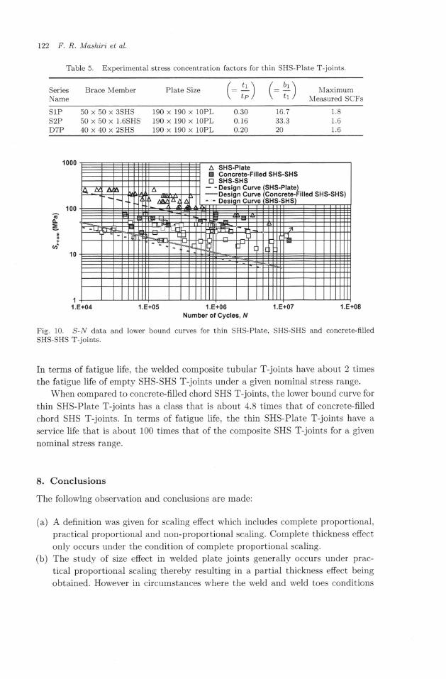
122 F- R. Mashiri et al.
Table 5. Experimental stress concentration factors for thin SHS-Plate T-joints.
Series Brace MemberName
r r \ / ôr \l : - | IVlaXlmUm
Lp / \ /r ,/ Measured SCFs
Plate Size {_\
S1PS2PD7P
50 x 50 x 3SHS 190 x50 x 50 x 1.6SHS 190 x40 x 40 x 2SHS 190 x
190 x190 x190 x
0.300.16o.20
1.81.6l .o
16.733.320
lOPLlOPLlOPL
o-=E
(tt
Number of Cycles, Â/
Fig. 10. ,S-N data and lower bound curves for thin SHS-Plate, SHS-SHS and concrete-filledSHS-SHS T-joints.
In terms of fatigue life, the welded composite tubular T-joints have about 2 times
the fatigue life of empty SHS-SHS T-joints under a given nominal stress range.
When compared to concrete-filled chord SHS T-joints, the lower bound curve for
thin SHS-Plate T-joints has a class that is about 4.8 times that of concrete-filled
chord SHS T-joints. In terms of fatigue life, the thin SHS-Plate T-joints have a
service life that is about 100 times that of the composite SHS T-joints for a given
nominal stress rânge.
8. Conclusions
The following observation and conclusions are made:
(a) A definition was given for scaiing effect which includes complete proportional,
practical proportional and non-proportional scaling. Complete thickness effect
only occurs under the condition of complete proportionai scaling.(b) The study of size effect in welded plate joints generally occurs under prac-
tical proportional scaling thereby resulting in a partial thickness effect being
obtained. However in circumstances where the weld and weld toes conditions
A SHS-PlateE Goncrete-Filled SHS-SHStr sHs-sHs
- - Design Curve (SHS-Plate)* Design Curve (Goncrete-Filled SHS-SHS)
1

I
Size Effect of Welded Thi,n-Walled Tubular Joi,nts 123
âre almost proportionally scaled, the category of scaling can be approximatedto complete proportional scaling resulting in complete thickness effect.
(c) The study of size effect in welded tubular nodal joints occurs under non-proportional scaling resulting in a partial thickness being derived.
(d) More research needs to be undertaken to understand the trend of thicknesseffect in thicker walled joints, with tube wall thicknesses or 27 beyond thecurrent validity range in fatigue design guidelines for welded tubular joints.
(e) The conventionally accepted phenomenon of size effect shows that fatiguestrength increases as the thickness of the member failing under fatiguedecreases. Recent research on welded thin-walled (t < 4 mm) tube-plate andtube tube T-joints has however shown that below a thickness of 4 mm, fatiguestrength actually decreases as the member failing under fatigue becomes thin-ner. This observation in thin-wailed joints can be attributed to the greaternegative impact that weld toe defects such as undercuts have on fatigue crackpropagation life.
(f) It has been demonstrated that boundary conditions have an effect on the rel-ative fatigue strength of welded joints. Joints with a higher stiffness have abetter fatigue life compared to joints of lower stiffness when subjected to thesame nominal stress ranse.
Acknowledgments
The authors would like to thank Dr. Ann Schumacher at Swiss Federal Laboratoriesfor Materials Testing and Research (trN'IPA) for her discussion on the terminologiesdescribed in this paper. The second author is grateful to ICOM, EPFL Lausanne forproviding support during his sabbatical leave when part of this paper was prepared.
Appendix - Notation
21 - (bslts) or (dsltg), chord width or chord diameterto chord wall thickness ratio
f : tube wall thicknessr : (tyfts), brace wall to chord wall thickness ratio
{3 : (br lbo) , (ù I do) , brace width to chord width ratioor brace diameter to chord diameter ratio
ly' : number of cycles to failurelo : chord wall thicknessf r : brace wall thickness
SHS : square hollow sectionCHS - circular hollow section
,S - stress rangeSrn" : hot spot stress rangeSCF : stress concentration factor

124 F. R. Mashi.ri et al.
br : brace width
bo : chord width
dr : brace diameterdo : chord diameter
Sr-.o- : nominal sPot stress range
1' : plate wall thickness
PWHT : post weld heat treatment,Ss : stress range of reference plate thickness fg
tn : reference plate thickness
WB : basic width corresponding to the basic design ,5-l/ curve.
Wt : aPPàrent width of the plate under consideration
HSSNR : hot spot strain range
Àt : number of cycles to through thickness crack
Tcr : wall thickness of cracked member
S.r,".t : hot spot stress range for tube wall thickness, t.
S,r'",re : hot spot stress range for reference tube wall thickness,
t : 16mm
len : effective thickness of main plate in cruciform type joints
SCF.o-po"11" : stress concentration factor for SHS-SHS T-joint
with concrete filled chord
SCF.-'1, : stress concentration factor for empty SHS-SHS T-joint
References
1. S. Berge, On the effect of plate thickness in fatigue of welds, Eng. Fract. Mech. 2L(t985\ 423-435
2. T. R. Gurney, The influence of thickness on fatigue of welded joints 10 years on
(a review of British work), in Proc. 9th Int. Conf. Offshore Mech. Arctic Eng.,"lhe
Hague, The Netherlands 3 (1989), pp. 1 8.
3. O. Vosikovsky, R. Bell, D. J. Burns and U. H. Mohaupt, Thickness effect on fatigue of
welded joints-review of the Canadian program, in Proc. 8th Int. Conf . Offshore Mech.
Arcti.c Eng., The Hague, The Netherlands 3 (1989). pp. 9 19.
4. J. de Back, D. R. V. van Delft and C. Noordhoek, The effect of plate thickness on
fatigue life of welded tubular joints and flat specimens, in Proc. 8th Int. Conf . Offshore
Mech. and Arcti,c Eng., The Netherlands 3 (1989), pp. 31-37.
5. A. NI. van Wingerde, D. R. V. van Delft. J. Wardenier and J. P. Packer, Scale effects
on the fatigue behaviour of tubular structures. in Proc. IIW Int. Conf. Performance
Dynam. Loaded Welded Struct., San Francisco, USA (1997). pp. 123-135.
6. SAA: Steel Structures. Australian Standard AS 4100-1998, Standards Association of
Austral ia. Sydney. Austral ia ( i998).7. Department of Energy, Offshore Installations: Gui,dance on Design, Construction and
Cerff icat ion,4th edn. (HMSO, London, UK, 1990).8. A. Hobbacher, Fatigue Design of Welded Joi,nts and Components, Recommendations
of IIW Joint Working Group XIII XV, XIII-1539-96/XV-845-96 (Abington Publish-
ing, Cambridge, trngland, 1996).

I
t
Size Effect of Weld,ed Thi,n-Walled. Tubular Joints 125
9. A. Schumacher, A. Nussbaumer and M. A. Hirt, Fatigue behaviour of welded CHSbridge joints: Emphasis on the effect of size, Tubular Structures X, in Proc. 10th Int.Sgmp. Tubular Struct., ISTS10, Madrid, Spain (2003), pp. 365-374.
10. I. F. C. Smith and T. R. Gurney, Changes in the fatigue life of plates with attachmentsdue to geometrical effects, Weldi,ng Research Suppli,ment, September issue (1g86)pp.244s 25Os.
11. H. Wohlfahrt, T. Nitschke-Pagel and W. Zinn, Improvement of the fatigue strengthof welded joints by post-weld treatment methods A comparison of the results ofhigh strength structural steels and high strength aluminium alloys, Weld'ing in theWorld/Soud,age dans le Monde 38 (1996) 307-316.
12. P. J. Haagensen and S. J. Maddox, IIW recommendations on post weld improve-ment of Steel and Aluminium Structures, IIW Commission XIII, Working Group 2- Improvement Techniques, XIII-1815-00, Prague, revised (2005).
13. S. Berge and S. tr. Webster, The size effect on the fatigue behaviour of welded joints,Paper PS 8, Developments in Marine Technology 3, in Proc. ?rd Int. Conf. SteelMarine Struct., SIMS'97, Delft. The Netherlands (1987), pp. 179 203.
1.4. y. Xue, J. Xu, H. Li and Y. Li, Influence of plate thickness on fatigue behaviour ofwelded joints in air and seawater, China Ocean Eng., 4(2) (1990) 179-188.
15. L S. Cole, O. Vittori and G. Cerretti, Cathodic protection and thickness effect: A finalconclusion?, in Proc. Srd Offshore Polar Eng. Conf.,Singapore (1993), pp.309-316.
16. IIW: Fatigue Design Proced,ures for Welded Hollow Section Joi,nts. IIW Doc. XIII-1804-99, IIW Doc. XV-1035-99, Recommendations for IIW Subcommission XV-E,eds. X. L. Zhao and J. A. Packer (Abington Publishing, Cambridge, UK, 2000).
17. X.L.Zhaa, S. Herion, J. A. Packer, R. Puthl i , G. Sedlacek, J. Wardenier, K. Weynand,A. Wingerde and N. Yeomans, Desi,gn Guide for C'ircular and, Rectangular HollowSecti,on Jo'ints under Fati,gue Loading (Verlag TUV Rheinland, Koln. Germany, 2000).
18. A. Schumacher, Fatigue behaviour of welded circular hollow section joints in bridges,PhD thesis No. 2727, Department of Civil Engineering, Faculty of Built Environmentand Architecture, Ecole Polytechnique Federale De Lausanne, Switzerland (2003).
19. S. Berge, The plate thickness effect in fatigue.predictions and results (a review ofNorwegian work), in Proc. 8th Int. Conf . Offshore Mech. Arcti,c Eng., The Hague,The Netherlands 111 (1989), pp. 21 30.
20. O. Ôrjasaeter, A. Drâgen, P. J. Haagensen, B. Lian and Â. Gunleiksrud, Effect ofplate thickness on the fatigue properties of low carbon-micro-alloyed steel, PaperTS 6, Developments in Nlarine Technology 3, in Proc. 9rd Int. Conf. Steel MarineStruct., SIMS'87, Delft, The Netherlands (1987), pp.315 335.
21. W. Weibull, Zur Abhangigkeit der Festigkeit von der Probengrosse, Ingenieur Archiu,28 (1959) 360 362.
22. G. Savaidis, A. Savaidis, G. Tsamasphyros and Ch. Zhang, On size and technologicaleffects in fatigue and prediction of engineering materials and components, Int. ,1.Mech. Sci. 44 (2002) 52r 543.
23. J. L. Overbeeke and H. Wildschut, The influence of plate thickness on the enduranceof welded joints, Paper TS 1, Developments in Marine Technology 3, in Proc. 9rd Int.Conf. Steel Mari,ne Struct., SIMS'97, Delft, The Netherlands (1987), pp.247,257.
24. S. Walbridge, A. Nussbaumer and M. A. Hirt, Fatigue behaviour of improved tubularbridge joints, tn 10th Int. Symp. Tubular Struct.. Madrid (2003).
25. C. E. Phillips and R. B. Heywood, The size effect in fatigue of plain and notchedspecimens loaded under reversed direct stress, Proc. Inst. Mech. Eng. 165 (1957)t13,124.
26. "1 . R. Gurney, Theoretical analysis of the influence of toe defects on the fatiguestrength of lillet weided joints, W'elding Institute Research Report 3211977 lE (1977).

L26 F. R. Mashiri et aI.
27. T. R. Gurney, The influence of thickness on the fatigue strength of welded joints,
Paper 41, in Proc. 2nd Int. Conf. Behauiour Offshore Struct., BOSS'79, London, Eng-land (1979), pp. 523 534.
28. U. H. Mohaupt, D. J. Burns, J. G. Kalbfleisch, O. Vosikovsky and R. Bell, Fatigue
crack development, thickness and corrosion effects in welded plate to plate joints,
Paper TS 3, Developments in Marine Technology 3, in Proc. 9rd Int. Conf. SteelMarine Stract., SIMS'87, Delft, The Netherlands (1987), pp. 269 280.
29. G. S. Booth, The effect of thickness on the fatigue strength of plate welded joints,
Paper TS 2, Developments in Marine Technology 3, in Proc. Srd Int. Conf. SteelMarine Struct., SIMS'87, Delft, The Netherlands (1987), pp. 259 268.
30. S. Berge, O. I. tride, O. C. Astrup, S. Palm, S. Wastberg, A. Gunleiksrud andB. Lian, Effect of plate thickness in fatigue of welded joints in air and in seawa-ter. Paper TS 45, Developments in lvlarine Technology 3, in Proc. 9rd Int. Conf . SteelMarine Struct., SIMS'S7, Delft, The Netherlands (1987), pp. 799-810.
31. C. Noordhoek, D. R. V. van Delft and A. Verheul, The influence of plate thicknesseson the fatigue behaviour of welded plates up to 160mm with an attachment or buttweld, Paper TS 4, Developments in Marine Technology 3,in Proc. Srd Int. Conf. SteelMorine Struct . . SIMS'87. Del f t . The Nether lands (1987), pp.28 l -301.
32. O. I. Eide and S. Berge, Fatigue of iarge scale plate girders with plate thicknesses 20,
40 and 60 mm, Paper TS 7, Deveiopments in N{arine Technology 3, in Proc. Srd Int.Conf. Steel Marine Struct., SIMS'87. Delfb, The Netherlands (1987), pp.337-347.
33. D. R. V. van Deift, C. Noordhoek and J. de Back, Evaluation of the European fatiguetest data on large size welded tubularjoints for offshore structures. in Proc. 17th Ann.Offshore Tech. Conf., Houston, Texas, OTC 4999 (1985), pp. 351-356.
34. IIW: Recommendations for fatigue design of welded joints and components, IIW Doc.XIII-i965-03/XV-1127-03, IIW Joints Working Group XIII-XV, IIW Annual Assem-
bly, Prague (2005).35. BSI, Fatigue design and assessment of steel structures, 857608, British Standards
Insti tut ion, London, UK (1993).
36. EC3, Eurocode 3: Design of Steel Structures-Part 1.9, Fatigue, European Committee
for Standardisat ion (2003).37. G. J. van der !'egte, Low cycle fatigue of welded structures-Part C: Tubular T- and
X-joints, Report Stevin Laboratory, Delft University of Technology, The Netherlands
( 1ee8).38. G. J. Hancock, Recent research and design developments in cold-formed open section
and tubular members, in Proc. 2nd Int. Conf. Adu. Steel Struct., ICASS'99, Hong
Kong L (1999), pp.25-37.39. ASTIvI: Standard Specificati.on for Cold-Formed Welded and SeamLess Carbon Steel
Structural Tubing in Rounds and Shapes-Specifi,cation A500-01, American Society for
Testing and Nlaterials, West Conshohocken, PA. USA (2001).40. SAA: Structural Steel Hollow Secti,ons, Australian Standard AS1163-1991, Standards
Association of Australia, Sydney, Australia (1991).
41. CtrN: Cold formed welded structural hollow sections of non-allov and fine grain
steels -Part 2: Tolerances, dimensions and sectional properties, EN10219-2: 1997,
Committee for European Standardization, Brussels (1997).
42. STI: Hollow Structural Sections-Principal Producers and Capabilities, Steel Tube
Irrstitute of North America, N{entor, Ohio, USA (2001).
43. F. R. Mashiri. X. L. Zhao, P. Grundy and L. Tong, Fatigue design of very thin-walled SHS-to-plate joints under in-plane bending, Thi.n-Walled Struct. 4O(2) (2002)
125-151.

ÀÀ
45
46.
4(.
48.
49.
50.
51.
52.
oJ.
S'ize Effect of Weld,ed, Thi,n-Walled. Tubular Joints 127
F. R. Mashiri , X. L. Zhao and P. Grundy, Fatigue tests and design of thin cold-formedsquare hollow section-to-piate T-connections under in-plane bending, J. struct. Eng.,ASCE r28(r) (2002) 22-3r.F. R. Mashiri, X. L. Zhao and P. Grundy, Fatigue tests and design of weldedT-connections in thin cold-formed square hollow sections under in-plane bending,J. Struct. Eng., ASCE 128(11) (2002) 1413 1422.F. R. Mashiri and X. L. zhao, Effect of thickness and joint type on fatigue performanceof welded thin-walled tube-plate T-joints, in Proc. lst Int. conf. Adu. Etp. struct.Eng. (AESE. 2005), Nagoya, Japan (2005), pp. 827 884.X. L Zhao and G. J. Hancock, Butt welds and transverse fillet welds in thin cold-formed RHS members, J. Struct. Eng. ASCE 121(11) (1995) 1674-1682.F. R. Mashiri, X. L. Zhao and P. Grundy, Fatigue behaviour of thin-walled tubetube T-joints under in-plane bending, TubuLar structures IX, in Proc gth Int. sgmp.Euroconf. Tubular Struct., Dùsseldorf, Germany. ISTS9 (2001), pp. 2bg 268.c. Noordhoek, J. wardenier and D. Dutta, The fatigue behaviour of welded joints insquare hollow sections-Part 2: Analysis, Stevin Report 6-80-4, TNO-IBBC Report8I-80-10/0063.4.3821. Department of civil Engineering, Delft university of rechnol-ogy, Delft, The Netherlands (1980).F. R. Mashiri, x. L. zhao and P. Grundy, Effects of weld undercut on the fatigue lifeof welded connections in thin-walled structures. in Proc. Struct. Integrity Fracture,Australian Fracture Group Inc., Melbourne, Australia (1998), pp. 81 g1.
F. R. Mashiri , X. L. Zhzn and P. Grundy, Effect of weld profile and undercut on fatiguecrack propagation life of thin-walled cruciform joint, Thin-walled Struct. s9(3) (2001)261 285.F. R. Mashiri and X. L. Zhao, Fatigue behaviour of welded composite tubular T-joints under in-plane bending, Thi,n-Walled Struct. Adu. Res. Des. Manufactur., inProc. lth Int. Conf . Thi,n-Walled Struct., Loughborough, United Kingdom, ICT-WS4(2004), pp. 491 498.F. R. Mashiri and X. L. Zhao, trffect of thickness and joint type on fatigue perfor-mance of weided thin-walled tube tube T-joints, tubular structure XI, in Proc. 11thInt. Symp. IIW Int. Conf. TubuLar Struct., ISTS11, Quebec City, Canada (2006),pp. 87-95.