Embed Size (px)
Citation preview
Analysis Methodologies for Beyond Design Basis
Accidents in SFR: Current Status and Future Directions
P.ChellapandiIndira Gandhi Centre for Atomic research
Kalpakkam-India
IAEA Workshop on Safety Aspects of Sodium Cooled Fast ReactorsIAEA Workshop on Safety Aspects of Sodium Cooled Fast Reactors2323--25 June, IAEA Headquarters, Vienna25 June, IAEA Headquarters, Vienna
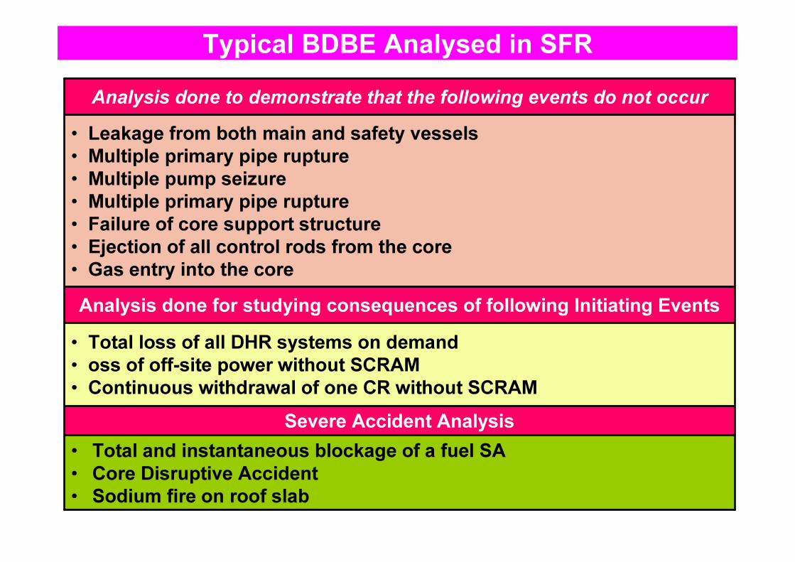
Typical BDBE Analysed in SFR
Severe Accident Analysis
Analysis done for studying consequences of following Initiating Events
Analysis done to demonstrate that the following events do not occur
• Total loss of all DHR systems on demand• oss of off-site power without SCRAM• Continuous withdrawal of one CR without SCRAM
• Total and instantaneous blockage of a fuel SA• Core Disruptive Accident• Sodium fire on roof slab
• Leakage from both main and safety vessels• Multiple primary pipe rupture• Multiple pump seizure• Multiple primary pipe rupture• Failure of core support structure• Ejection of all control rods from the core• Gas entry into the core
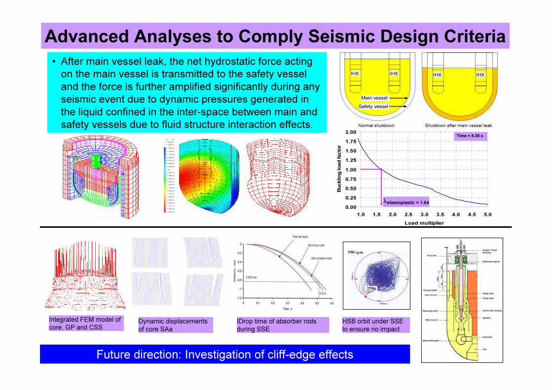
Advanced Analyses to Comply Seismic Design Criteria• After main vessel leak, the net hydrostatic force acting on the main vessel is transmitted to the safety vessel and the force is further amplified significantly during any seismic event due to dynamic pressures generated in the liquid confined in the inter-space between main and safety vessels due to fluid structure interaction effects.
IHX IHX IHX IHX
Safety vesselMain vessel
IHX IHX IHX IHX
Safety vesselMain vessel
0.000.250.500.751.001.251.501.752.00
1.0 1.5 2.0 2.5 3.0 3.5 4.0 4.5 5.0Load multiplier
Buck
ling l
oad f
actor
λelastoplastic = 1.64
Time = 8.25 s
0's
Integrated FEM model of core, GP and CSS Dynamic displacements
of core SAaIDrop time of absorber rods during SSE
HSB orbit under SSE to ensure no impact
Future direction: Investigation of cliff-edge effects
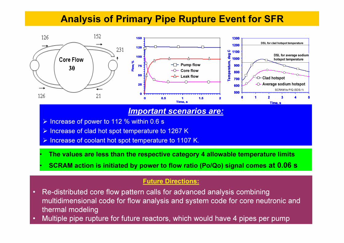
Analysis of Primary Pipe Rupture Event for SFR
Important scenarios are: � Increase of power to 112 % within 0.6 s� Increase of clad hot spot temperature to 1267 K � Increase of coolant hot spot temperature to 1107 K. • The values are less than the respective category 4 allowable temperature limits • SCRAM action is initiated by power to flow ratio (Po/Qo) signal comes at 0.06 s
Future Directions:• Re-distributed core flow pattern calls for advanced analysis combining
multidimensional code for flow analysis and system code for core neutronic and thermal modeling
• Multiple pipe rupture for future reactors, which would have 4 pipes per pump
0
25
50
75
100
125
150
0 0.5 1 1.5 2Time, s
Flow,
%
PSP-1 flowCore flowLeak flow
Pump flowCore flowLeak flow
0
25
50
75
100
125
150
0 0.5 1 1.5 2Time, s
Flow,
%
PSP-1 flowCore flowLeak flow
Pump flowCore flowLeak flow
500600700800900
1000110012001300
0 1 2 3 4 5Time, s
Temp
eratur
e, de
g C
Clad hotspotAverage sodium hotspot
DSL for clad hotspot temperature
DSL for average sodiumhotspot temperature
SCRAM by P/Q (SDS-1)
Clad hotspotAverage sodium hotspot
DSL for average sodiumhotspot temperature
500600700800900
1000110012001300
0 1 2 3 4 5Time, s
Temp
eratur
e, de
g C
Clad hotspotAverage sodium hotspot
DSL for clad hotspot temperature
DSL for average sodiumhotspot temperature
SCRAM by P/Q (SDS-1)
Clad hotspotAverage sodium hotspot
500600700800900
1000110012001300
0 1 2 3 4 5Time, s
Temp
eratur
e, de
g C
Clad hotspotAverage sodium hotspot
DSL for clad hotspot temperature
DSL for average sodiumhotspot temperature
SCRAM by P/Q (SDS-1)
Clad hotspotAverage sodium hotspot
DSL for average sodiumhotspot temperature
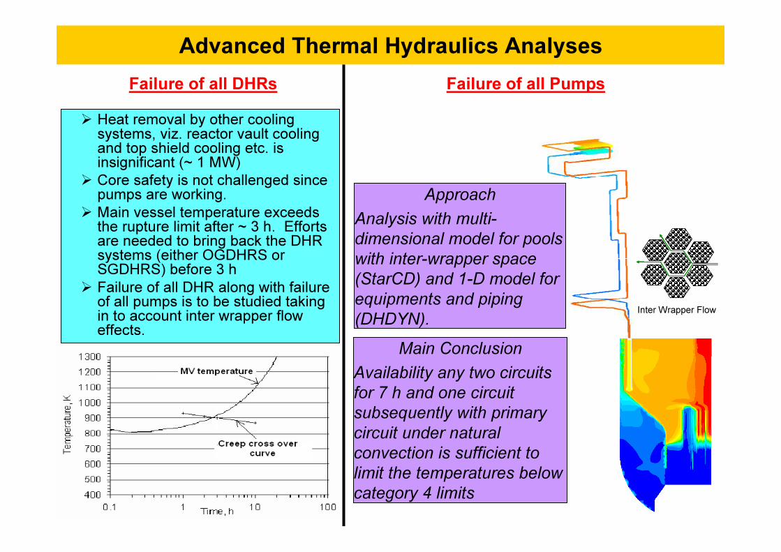
Advanced Thermal Hydraulics Analyses
� Heat removal by other cooling systems, viz. reactor vault cooling and top shield cooling etc. is insignificant (~ 1 MW)
� Core safety is not challenged since pumps are working.
� Main vessel temperature exceeds the rupture limit after ~ 3 h. Efforts are needed to bring back the DHR systems (either OGDHRS or SGDHRS) before 3 h
� Failure of all DHR along with failure of all pumps is to be studied taking in to account inter wrapper flow effects.
Failure of all DHRs Failure of all Pumps
Approach Analysis with multi-dimensional model for pools with inter-wrapper space (StarCD) and 1-D model for equipments and piping (DHDYN).
Main Conclusion Availability any two circuits for 7 h and one circuit subsequently with primary circuit under natural convection is sufficient to limit the temperatures below category 4 limits
Inter Wrapper Flow

Formation vortex around PSP shaftAnalysis Method:§CFD prediction of gas entrainment at its infancy. Codes used: PHOENICS, STAR-CD & OpenFOAM.§Phenomenon is governed by Froude, Weber & Reynolds (Re) numbers. Respecting Froude and Weber numbers, water
model demands a large scale of 5:8.
Gas Entrainment in SFR
Future Direction:§ Development of CFD based model to predict physical, chemical and thermal aspects of gas entrainment scenario
and coupling it with neutronics for reactivity feedback and power evolution
Design Solutions:§ Horizontal baffle in hot pool to minimize free surface velocity to ~ 0.5 m/s. Overflow weir in MV cooling system to
avoid flow separation sufficient sodium depth in restitution plenum . Provision of purger SA in grid plate.
Main vessel cooling system Vortex activation in hot pool
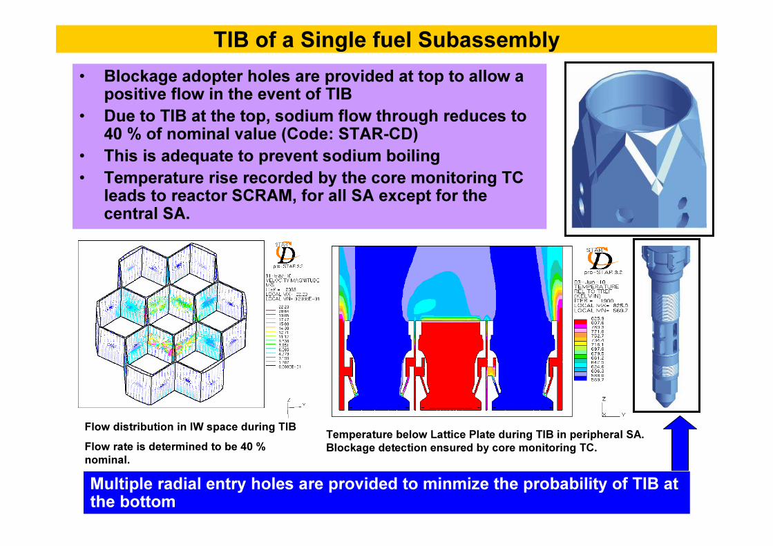
TIB of a Single fuel Subassembly • Blockage adopter holes are provided at top to allow a
positive flow in the event of TIB• Due to TIB at the top, sodium flow through reduces to
40 % of nominal value (Code: STAR-CD)• This is adequate to prevent sodium boiling• Temperature rise recorded by the core monitoring TC
leads to reactor SCRAM, for all SA except for the central SA.
Flow distribution in IW space during TIBFlow rate is determined to be 40 % nominal.
Temperature below Lattice Plate during TIB in peripheral SA. Blockage detection ensured by core monitoring TC.
Multiple radial entry holes are provided to minmize the probability of TIB at the bottom

• Preliminary Deformations of Components (0 - 50 ms)• Upward Motion of Sodium Slug (50 – 100 ms)• Sodium Slug Impact on top shield and development of Transient
Forces on Reactor Vault (100-150 ms).• Sodium Release to RCB during quasi-static state (150 – 900 ms)• Post Accident Heat Removal Condition depending upon coolability
of core bubble (> 900 ms)• Effects of internals contribute by changing (i) energy release, (ii)
transient forces and (iii) duration of major phenomenon, by virtue of their geometrical features, location and inertial characteristics.
Analysis of Mechanical Consequences of CDA

Lagrangian Codes:• REXCO-H developed at ANL (FFTF)• REXCO-HEP and ASTARTE of UKAEA• ARES of Interatom Germany (SNR-300)• SIRIUS of CEA France (SPX-1 and SPX-2).
Eulerian Codes:• ICECO, developed in 1975. • SEURBNUK-2 by Euratom, Belgonucleaire, and the UK for the analysis CDFR and SNR-300
• PISCES 2 DELK, an Eulerian version of the PISCES code.
Eulerian-Lagrangian Coupled Codes: • CASSIOPEE (SPX-1)• EURDYN (SPX-1 and SPX-2)• ALICE (CRBRP)• PLEXUS (EFR)• FUSTIN (PFBR)
International Computer Codes
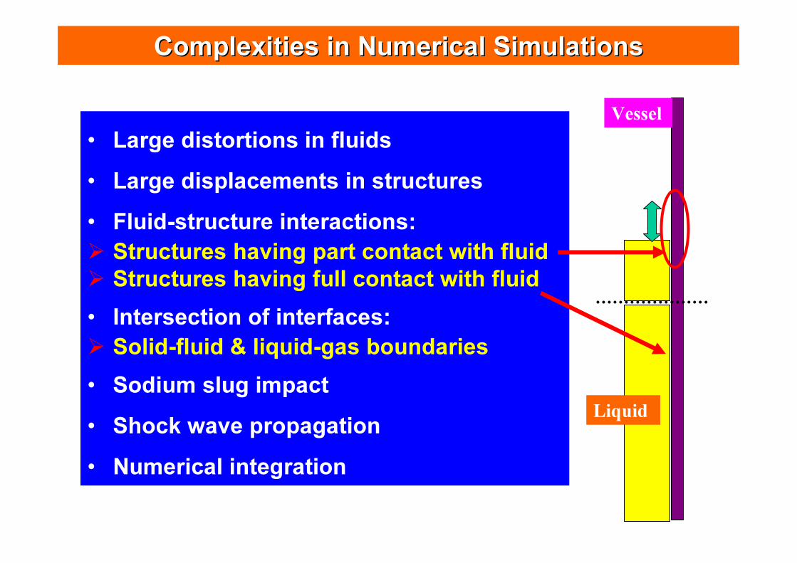
Complexities in Numerical SimulationsComplexities in Numerical Simulations
• Large distortions in fluids• Large displacements in structures• Fluid-structure interactions:� Structures having part contact with fluid� Structures having full contact with fluid• Intersection of interfaces:� Solid-fluid & liquid-gas boundaries• Sodium slug impact• Shock wave propagation• Numerical integration
Vessel
Liquid
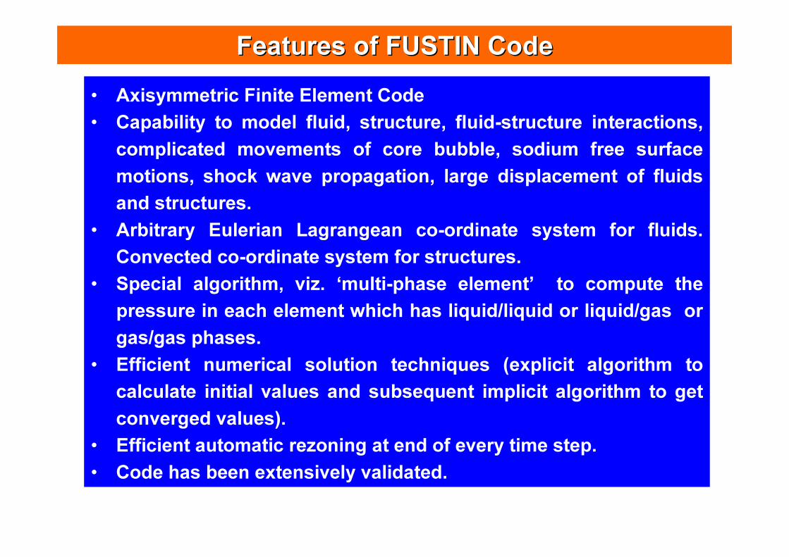
Features of FUSTIN CodeFeatures of FUSTIN Code• Axisymmetric Finite Element Code• Capability to model fluid, structure, fluid-structure interactions,
complicated movements of core bubble, sodium free surface motions, shock wave propagation, large displacement of fluids and structures.
• Arbitrary Eulerian Lagrangean co-ordinate system for fluids. Convected co-ordinate system for structures.
• Special algorithm, viz. ‘multi-phase element’ to compute the pressure in each element which has liquid/liquid or liquid/gas or gas/gas phases.
• Efficient numerical solution techniques (explicit algorithm to calculate initial values and subsequent implicit algorithm to get converged values).
• Efficient automatic rezoning at end of every time step. • Code has been extensively validated.
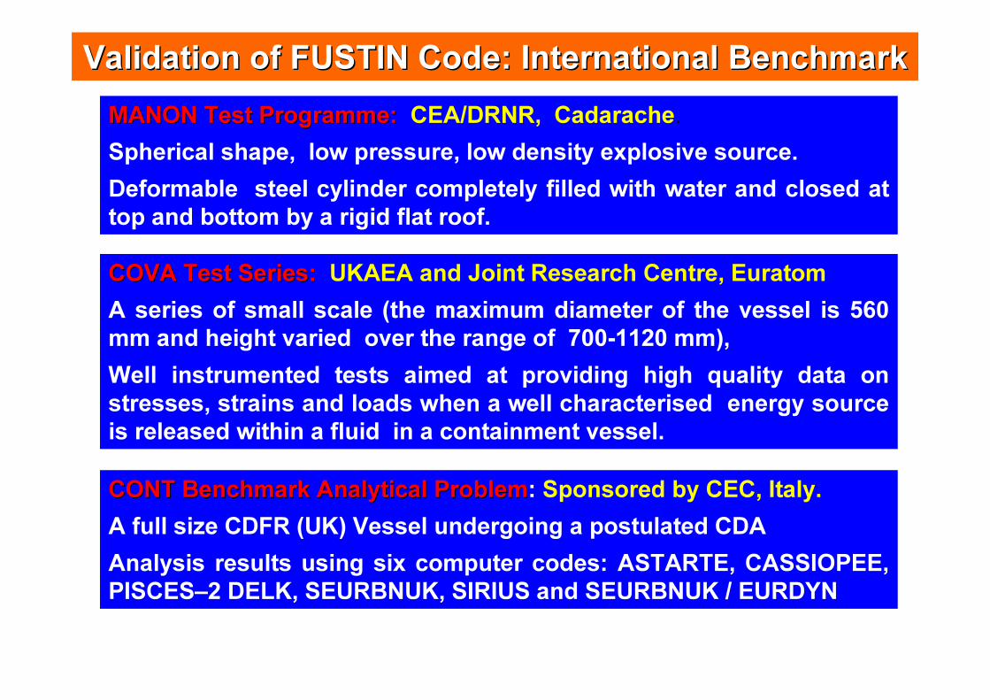
Validation of FUSTIN Code: International BenchmarkValidation of FUSTIN Code: International Benchmark
CONT Benchmark Analytical ProblemCONT Benchmark Analytical Problem: Sponsored by CEC, Italy.A full size CDFR (UK) Vessel undergoing a postulated CDA Analysis results using six computer codes: ASTARTE, CASSIOPEE, PISCES–2 DELK, SEURBNUK, SIRIUS and SEURBNUK / EURDYN
MANON Test Programme:MANON Test Programme: CEA/DRNR, Cadarache. Spherical shape, low pressure, low density explosive source. Deformable steel cylinder completely filled with water and closed at top and bottom by a rigid flat roof.
COVA Test Series: COVA Test Series: UKAEA and Joint Research Centre, EuratomA series of small scale (the maximum diameter of the vessel is 560 mm and height varied over the range of 700-1120 mm), Well instrumented tests aimed at providing high quality data on stresses, strains and loads when a well characterised energy source is released within a fluid in a containment vessel.
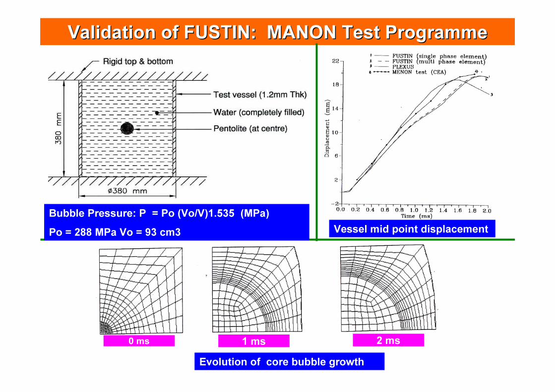
Validation of FUSTIN: MANON Test ProgrammeValidation of FUSTIN: MANON Test Programme
Vessel mid point displacement
Evolution of core bubble growth0 ms 1 ms 2 ms
Bubble Pressure: P = Po (Vo/V)1.535 (MPa) Po = 288 MPa Vo = 93 cm3
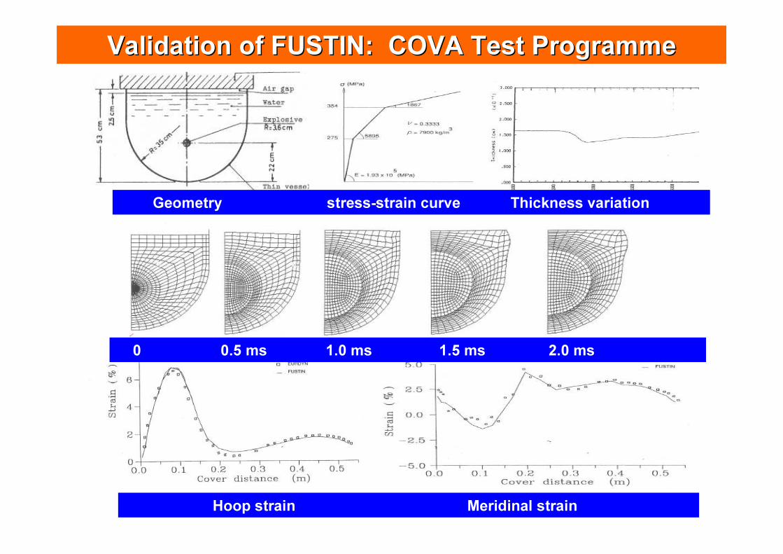
Validation of FUSTIN: COVA Test ProgrammeValidation of FUSTIN: COVA Test Programme
Geometry stress-strain curve Thickness variation
Hoop strain Meridinal strain
0 0.5 ms 1.0 ms 1.5 ms 2.0 ms
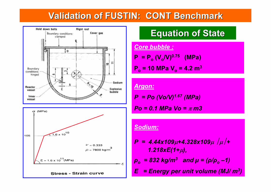
Validation of FUSTIN: CONT BenchmarkValidation of FUSTIN: CONT Benchmark
Core bubble :P = Po (Vo/V)0.75 (MPa) Po = 10 MPa Vo = 4.2 m3
Argon:P = Po (Vo/V)1.67 (MPa) Po = 0.1 MPa Vo = π m3
Equation of StateEquation of State
Sodium:
P = 4.44x10⁹µ+4.328x10⁹µ µ+ 1.218xE(1+µ),
ρo = 832 kg/m3 and µ = (ρ/ρo –1) E = Energy per unit volume (MJ/ m3)
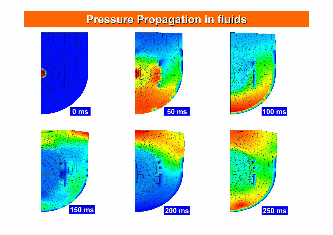
0 ms 50 ms 100 ms
150 ms 200 ms 250 ms
Pressure Propagation in fluidsPressure Propagation in fluids
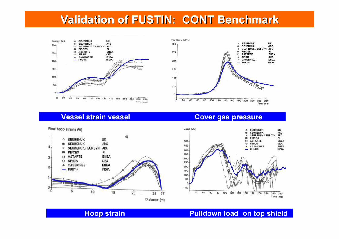
Validation of FUSTIN: CONT BenchmarkValidation of FUSTIN: CONT Benchmark
Vessel strain vessel Cover gas pressure
Hoop strain Pulldown load on top shield
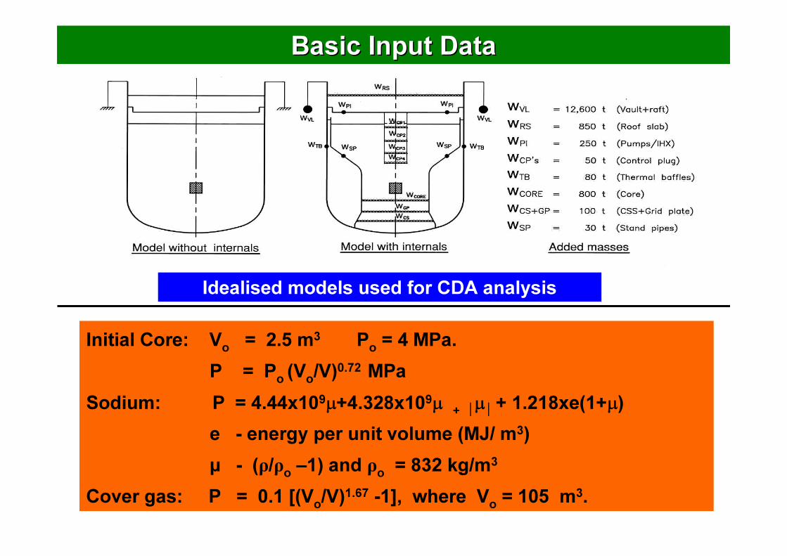
Basic Input DataBasic Input Data
Initial Core: Vo = 2.5 m3 Po = 4 MPa. P = Po (Vo/V)0.72 MPa
Sodium: P = 4.44x10⁹µ+4.328x10⁹µ + µ + 1.218xe(1+µ) e - energy per unit volume (MJ/ m3) µ - (ρ/ρo –1) and ρo = 832 kg/m3
Cover gas: P = 0.1 [(Vo/V)1.67 -1], where Vo = 105 m3.
Idealised models used for CDA analysis
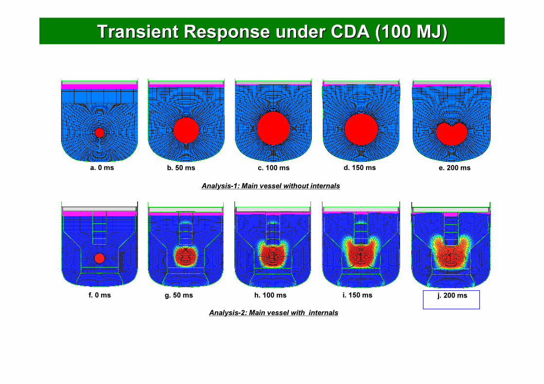
Transient Response under CDA (100 MJ)Transient Response under CDA (100 MJ)
f. 0 ms g. 50 ms h. 100 ms i. 150 ms j. 200 ms
Analysis-1: Main vessel without internals
Analysis-2: Main vessel with internals
a. 0 ms b. 50 ms c. 100 ms d. 150 ms e. 200 ms
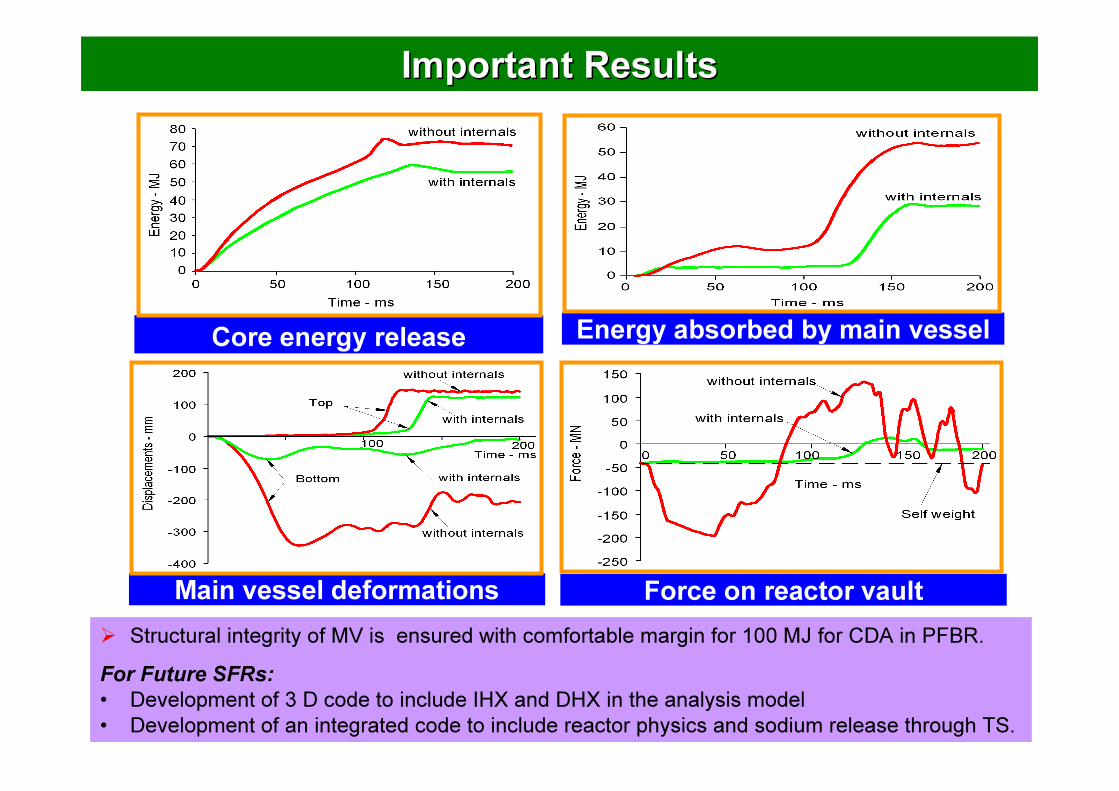
Important Results Important Results
Main vessel deformations
Core energy release Energy absorbed by main vessel
Force on reactor vault� Structural integrity of MV is ensured with comfortable margin for 100 MJ for CDA in PFBR.For Future SFRs:• Development of 3 D code to include IHX and DHX in the analysis model• Development of an integrated code to include reactor physics and sodium release through TS.
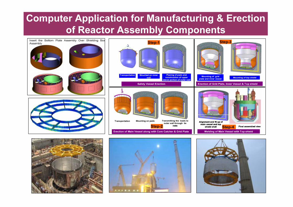
Transportation Mounted on inner wall
Placing of pads and construction of upper
lateral portion of outer wallSafety Vessel Erection
Transportation Mounting on pads Transmitting the loads to outer wall through tie
rods
Erection of Main Vessel along with Core Catcher & Grid Plate
Erection of Grid Plate, Inner Vessel & Top shield
Mounting of grid plate and inner vessel Mounting of top shield
Welding of Main Vessel with Top shield
Alignment and fit up of main vessel and top
shield shell Final assembled view
Step-1
Step-2
Step-3
Step-4
Transportation Mounted on inner wall
Placing of pads and construction of upper
lateral portion of outer wallSafety Vessel Erection
Transportation Mounting on pads Transmitting the loads to outer wall through tie
rodsTransportation Mounting on pads Transmitting the loads to
outer wall through tie rods
Erection of Main Vessel along with Core Catcher & Grid Plate
Erection of Grid Plate, Inner Vessel & Top shield
Mounting of grid plate and inner vessel Mounting of top shield
Welding of Main Vessel with Top shield
Alignment and fit up of main vessel and top
shield shell Final assembled view
Step-1
Step-2
Step-3
Step-4
Computer Application for Manufacturing & Erection of Reactor Assembly Components
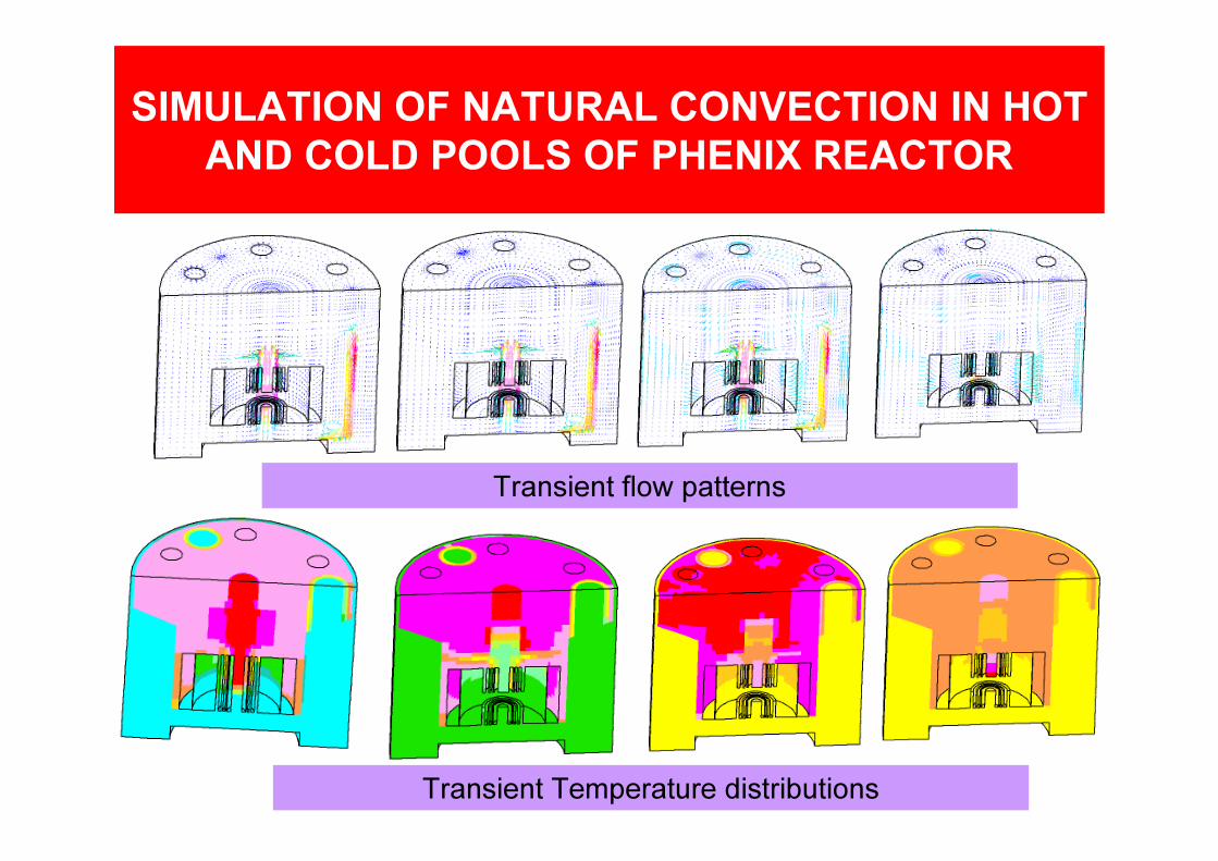
Transient flow patterns
Transient Temperature distributions
SIMULATION OF NATURAL CONVECTION IN HOT AND COLD POOLS OF PHENIX REACTOR
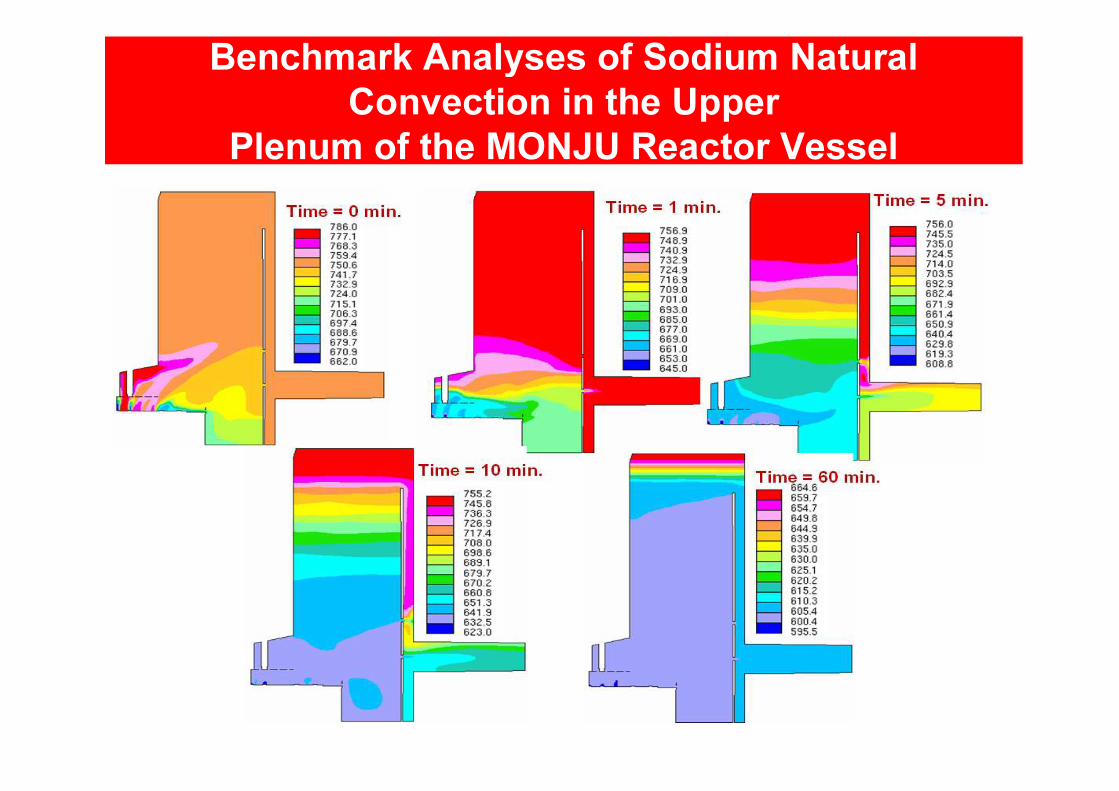
Benchmark Analyses of Sodium Natural Convection in the Upper
Plenum of the MONJU Reactor Vessel
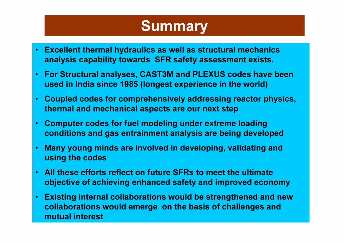
Summary• Excellent thermal hydraulics as well as structural mechanics
analysis capability towards SFR safety assessment exists.• For Structural analyses, CAST3M and PLEXUS codes have been
used in India since 1985 (longest experience in the world)• Coupled codes for comprehensively addressing reactor physics,
thermal and mechanical aspects are our next step• Computer codes for fuel modeling under extreme loading
conditions and gas entrainment analysis are being developed• Many young minds are involved in developing, validating and
using the codes • All these efforts reflect on future SFRs to meet the ultimate
objective of achieving enhanced safety and improved economy• Existing internal collaborations would be strengthened and new
collaborations would emerge on the basis of challenges and mutual interest
IGCAR, Kalpakkam 25