Embed Size (px)
Citation preview

© 2014 Discovery Publication. All Rights Reserved. www.discoveryjournals.com OPEN ACCESS
ARTICLE
Page
84
ANALYSIS
Performance appraisal of high temperature annular recuperator with parallel flow configuration using fluent Saurav S1҉, Anoop K2, Jitendra KC1, Naveen K1 1. Research Scholar, Department of Mechanical Engineering, NIT-Hamirpur, HP-177005, India 2. Professor, Department of Mechanical Engineering, NIT-Hamirpur, HP-177005, India ҉Corresponding Author: Research Scholar, Department of Mechanical Engineering, NIT-Hamirpur, HP-177005, India; E-mail address: [email protected] Publication History Received: 13 October 2014 Accepted: 26 November 2014 Published: 1 December 2014 Citation Saurav S, Anoop K, Jitendra KC, Naveen K. Performance appraisal of high temperature annular recuperator with parallel flow configuration using fluent. Discovery, 2014, 26(95), 84-96
Publication License
This work is licensed under a Creative Commons Attribution 4.0 International License. General Note
Article is recommended to print as color digital version in recycled paper.
ABSTRACT A double-shell annular recuperator consists of two concentric metallic shells connected at each end by way of air inlet and outlet headers. Radiation is the dominant mode in the inner shell while the air is heated due to convection. In the present study, heat transfer analysis of a single pass double shell metallic annular recuperator is done where the shape, size, configuration, flow arrangement, type of the materials used, surface geometries, mass flow rates, and the inlet temperature of the hot flue gases and combustion air are known. The gaseous radiation is dominated by emission and absorption due to CO2 and H2O vapor. The recuperator is modeled on a commercial software tool ANSYS FLUENT with Ansys Workbench. DOM is used for radiation, which is coupled with energy equation. Boundary conditions, operating conditions, design parameters are selected from earlier published works. The results in terms of axial temperature distributions and effectiveness have been obtained for different operating conditions as, inlet flue gas temperature and mass flow rate on different height of the recuperator for parallel flow configuration.
ANALYSIS 26(95), December 1, 2014
Discovery ISSN 2278–5469
EISSN 2278–5450

© 2014 Discovery Publication. All Rights Reserved. www.discoveryjournals.com OPEN ACCESS
ARTICLE
Page
85
ANALYSIS
The results obtained in this work will also help to identify the relative merits and limitations of metallic annular recuperator in different operating conditions and configuration. Keywords: Thermal Radiation, Recuperator, RTE, WSGGM, DOM, FLUENT Abbreviations: RTE- Radiative Transfer Equation, DOM- Discrete Ordinate Model, WSGGM- Weighted Sum of Gray Gas Model Symbols: a- Absorption coefficient, Cp- specific heat (kJ kg-1 K-1), E- enthalpy (kJ/kg), I- intensity, K- thermal conductivity, L- height/length of the recuperator (m), M- mass fraction, m- mass flow rate (kg s-1), r- space coordinate, ŝ- unit direction vector, T- absolute temperature (K), t- time, ρ- density (m3/kg), σ- scattering coefficient, Ω- solid angle (steradian), Φ- scattering phase function Subscripts: a- air, g- gas, in- inlet, o- outlet, f- fuel 1. INTRODUCTION Due to the increasing cost of fossil fuels, there is heightened interest for fuel savings in fiber glass, glass, steel, aluminium and other metal melting industries (Shah et al., 2000). In high temperature furnaces (650ºC-1650ºC), 40 to 70% of the available heat is wastefully carried in the flue gases (US DOE EIA, 2006), this resulting in decreased plant efficiency, economic losses and increased pollution due to unutilized flue gases heat. Waste heat in the high-temperature range is not only the highest quality but is the most useful, and it costs less per unit to transfer than lower-quality heat. The equipment needs in the highest part of the range required special engineering and special materials. The strategy of how to recover hot flue gas heat depends in part on the temperature of the waste heat gases (Turner and Doty, 2009).
Jacobs (1957) proposed a design in which the heat transfer agents before inlet to annular passage were made to pass through a channel consisting of vanes, so as to impart twisting motion to increase the heat transfer rate. Earlier recuperators were less efficient when operated at load less than their rated load. Schack (1959) proposed a simple construction to overcome the drawback without any danger of breakdown and without sacrificing the efficiency of operation. Radiation recuperators due to their large passageways were difficult to manufacture as a single unit. Seehausen (1967) proposed a new efficient model having more strength at high temperatures and was easier to assemble. Among the 35% useful output, only 4% is contributed by convection while all the other heat transfer is from radiation. Radiation consists of radiation to wall, gas intercepted radiation to wall and gas intercepted radiation (Enomot et al., 1975). A portion of this waste heat at high temperature is recovered by employing a radiation recuperator. Within the recuperator, heat is transferred from the products of combustion to the air predominantly by radiation. If recuperators are used with industrial furnaces then fuel consumption will reduce and furnace efficiency will increase by preheating the combustion air utilizing heat from the furnace exhausts (Sharma et al., 2014).
Khoshmanesh et al. (2007) studied the three independent solutions to reduce the fuel consumption in industrial glass melting furnace. A reduction in the fuel consumption by 9.5%, 17% and 34%, respectively was observed by air preheating, raw material preheating, and improving the insulation of combustion space refractory. Sharma et al. (2012) investigated the performance model for parallel flow arrangement in metallic concentric tube recuperator that can be used to utilize the waste heat in the temperature range of 1100-1800 K is presented. The recuperator height is divided into small elements and an energy balance is performed on each element by zonal element method. Necessary information about axial shell surface, gas and air temperature distribution, and the influence of operating conditions on recuperator performance is obtained. The recuperative effectiveness is found to be increased with increasing inlet gas temperature and with decreasing fuel flow rate.
The focus is on combined convection and radiation in a gas, or a gas mixture, where accurate modeling of radiative transfer is required. The early work on radiative transfer in engineering problems has been primarily concerned with the methods for solving the radiative transfer equation, using very simple gas radiation property (i.e. gray) models and on coupling radiation to convection (Viskanta, 1998). Park et al. (2008) analyzed the radiative heat transfer characteristics in a three-dimensional cube filled with gas mixtures of H2O, CO2 and N2. The characteristics of the radiative properties of gas mixtures were studied by using WSGGM-RG. For the analysis of the radiative heat transfer equations, DOM and RTM were used as the method of solution. WSGGM-RG together with DOM can be used to calculate fast for accurate results from an engineering perspective. Rek et al. (2012) dealt with the application of Computational Fluid Dynamics simulation in the development of a new generation cooking appliance in Gorenje concern. As the oven is multifunctional, radiation, conduction, natural and forced convection mechanisms of heat transfer are used. The Discrete

© 2014 Discovery Publication. All Rights Reserved. www.discoveryjournals.com OPEN ACCESS
ARTICLE
Page
86
ANALYSIS
Ordinate (DO) model is used for radiation. Holkar and hebbal (2013) had analyzed pulverized coal in combustion chamber design to achieve optimum operating conditions that give maximum combustion efficiency, together with minimum pollutant formation rate with the help of radiative heat transfer methods, the P-1 approximation method, Discrete Transfer and the discrete ordinates
1.1. Effectiveness of the recuperator After determination of outlet temperatures of flue gas and combustion air, the effectiveness (Shah and Dušan, 2003) of recuperator is calculated as: ξ = (Ta,o-Ta,in)/(Tg,in-Ta,in) 1 2. MODELING AND GOVERNING EQUATIONS This section deals with the development of simulation process of a single-pass, metallic annular radiation recuperator in parallel flow configurations. Here the shape, size, configuration, flow arrangement, type of the materials used, surface geometries, mass flow rates and the inlet temperature of the hot flue gases and combustion air are known. Fig. 1 shows the different control volumes together with the dimensions of the recuperator in parallel flow arrangements. The outside surface of the enclosing shell (surface-4) is insulated to increase the thermal effectiveness of the system and is referred to as surface-5.
Figure 1 Schematic diagram of annular recuperator in parallel flow
2.1. Governing Equations Temperature distribution and air-gas circulation in the recuperator are governed by conservations equations. The system of partial differential equations is: Mass conservation:
Momentum conservation:
Where is the velocity vector, is the stress tensor, and are the gravitational body force and external body forces respectively,
Energy conservation:
Where, Jj is the diffusion flux of species j. The first three terms of right hand side of equation represent energy transfer due to conduction, species diffusion and viscous dissipation respectively.
© 2014 Discovery Publication. All Rights Reserved. www.discoveryjournals.com OPEN ACCESS
ARTICLE
Page
87
ANALYSIS
Radiation Intensity conservation:
Where, n is refractive index. 2.2. Geometry generation
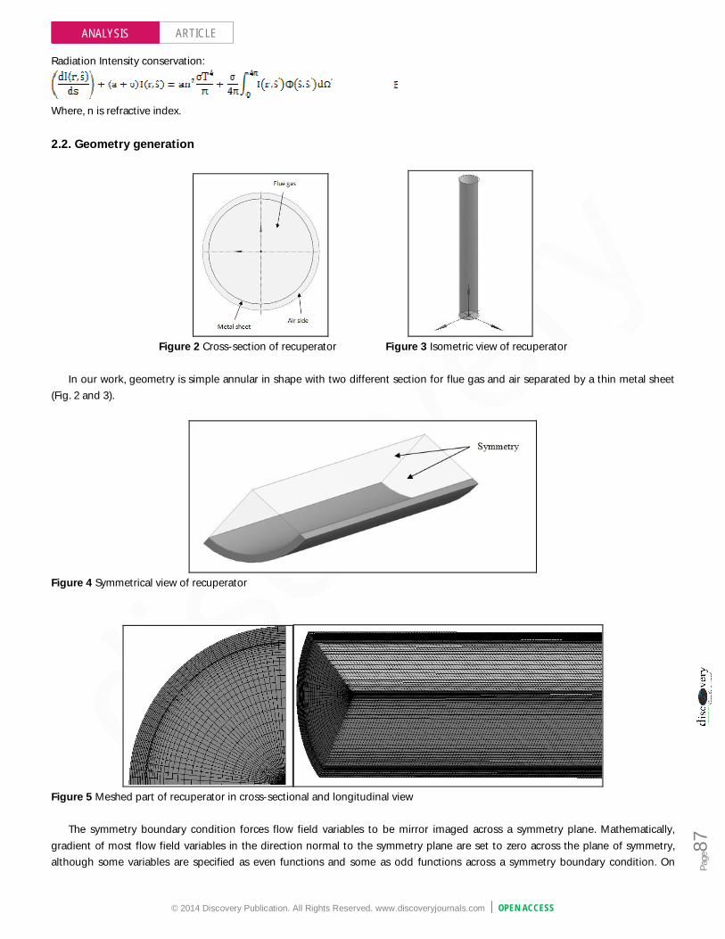
Figure 2 Cross-section of recuperator Figure 3 Isometric view of recuperator
In our work, geometry is simple annular in shape with two different section for flue gas and air separated by a thin metal sheet
(Fig. 2 and 3).
Figure 4 Symmetrical view of recuperator
Figure 5 Meshed part of recuperator in cross-sectional and longitudinal view
The symmetry boundary condition forces flow field variables to be mirror imaged across a symmetry plane. Mathematically, gradient of most flow field variables in the direction normal to the symmetry plane are set to zero across the plane of symmetry, although some variables are specified as even functions and some as odd functions across a symmetry boundary condition. On

© 2014 Discovery Publication. All Rights Reserved. www.discoveryjournals.com OPEN ACCESS
ARTICLE
Page
88
ANALYSIS
applying symmetry option on the recuperator, only one-fourth part of recuperator need to be analyzed for better performance of computer and better visualization of different properties (Fig. 4). 2.3. Grid generation Grid generation process has been carried out in ‘ANSYS ICEM CFD’ component available in ANSYS Workbench to minimize the connectivity problem between CAD software and meshing software (Fig. 5). If we want a swept mesh on a model that revolves around an axis where the source and target faces share topology, then sweep method is used for better meshing. The body can be meshed very efficiently with hexahedral and wedge elements using this technique. Workbench will mesh the source face with quadrilateral and triangular faces and then copy that mesh onto the target face. Fig. 5 display swept meshes involving mapped and paved source surfaces.
2.4. Species model The concept of mixture materials has been implemented in ANSYS FLUENT to facilitate the setup of species transport for flue gases mixture. A mixture material may be thought of as a set of species and a list of rules governing their interaction. A list of mixing laws is dictating how mixture properties (density, viscosity, specific heat, etc.) are to be derived from the properties of individual species if composition-dependent properties are desired. Diffusion coefficients for individual species in the mixture and other material properties (e.g., absorption and scattering coefficients) that is not associated with individual species. Adding and reordering the species was done in properties of mixture template (mixture species option). If the last species in the selected species list is not the most abundant species, it will need to rearrange the species to obtain the proper order. Table 1 Properties of species transport model
Mixture template properties Formulation/value Absorption coefficient Wsggm-domain-based
Mixture species CO2, H2O, O2, N2 Density Incompressible ideal gas
Specific heat Mixing-law Mass diffusivity Constant-dilute-approximation Refractive index 1
2.5. Radiation model The discrete ordinates (DO) radiation model solves the radiative transfer equation (RTE) for a finite number of discrete solid angles, each associated with a vector direction ŝ fixed in the global Cartesian system (x,y,z). The fineness of the angular discretization is controlled by us, analogous to choosing the number of rays for the DTRM. The DO model transforms RTE into a transport equation for radiation intensity in the spatial coordinates. The DO model solves for as many transport equations as there are directions ŝ. The solution method is identical to that used for the fluid flow and energy equations, so we go for the discrete ordinate method (DO model).
Two implementations of the DO model are available in ANSYS FLUENT: uncoupled and (energy) coupled. The uncoupled implementation is sequential in nature and uses a conservative variant of the DO model called the finite-volume scheme, and its extension to unstructured meshes. In the uncoupled case, the equations for the energy and radiation intensities are solved one by one, assuming prevailing values for other variables. For problems involving symmetry, periodic, specular, or semi-transparent boundaries, a pixelation of 3×3 is recommended. In our problem, we gave pixelation of 5×5 for better treatment. 2.6. Material Properties All of the gases of mixture template have piecewise polynomial (temperature dependent) specific heat capacity. The specific heat capacity for each species is calculated as:

© 2014 Discovery Publication. All Rights Reserved. www.discoveryjournals.com OPEN ACCESS
ARTICLE
Page
89
ANALYSIS
Polynomial coefficients are default in ANSYS. Since properties of air varies according to temperature, so we give piecewise linear (temperature dependent) option to properties (density, specific heat, thermal conductivity, viscosity). The material for the inner shell is taken as chromium steel to withstand high temperatures, which have thermal conductivity of 35 (W/m K).
2.7. Boundary Conditions Since mass flow rate is given on inlet condition, so we treat gas inlet and air inlet as mass flow boundary condition. At gas outlet and air outlet, it is given as pressure boundary condition. Boundary condition on different zone is given below as: a. Mass-flow gas-inlet: In momentum, mass flow rate is 0.92 kg/s, 2.13 kg/s, 3.2 kg/s one by one as par our analysis
requirements. Turbulence intensity is 10% and turbulent viscosity ratio is 10. In thermal, temperature is set to 1648 K, 1473 K, and 1173 K for different analysis. In radiation, internal emissivity is set to 0.4 (as par Leckner correlation, Modest, 1993). In species mass fraction, both CO2 and H2O are set to be on 0.1.
b. Mass-flow air-inlet: In momentum, mass flow rate is 0.87 kg/s, 2 kg/s, 3 kg/s respectively. Turbulent intensity and ratio are 2 because of thin gap for air. In thermal, temperature is set to be on atmospheric temperature (303 K).
c. Wall-part flue-gas metal-part: Thermal condition is coupled; internal emissivity is set to be 0.6; radiation boundary condition is opaque; CO2 and H2O species mass fraction are set to be on 0.15 and 0.1 respectively.
d. Wall-part air metal-part: Similar to wall part flue-gas metal-part, but not involve the species mass fraction. e. Outer wall: Emissivity is set to 0.55 as par given in references. f. Symmetry boundary: Flue gas, metal and air part of recuperator are taken as symmetry boundary condition on x-y plane and
y-z plane. 2.8. Solver Control Since each control volume has a residual we usually look at the RMS average or the maximum normalized residual. In our system, we use both average residual targets. For reasonable convergence MAX residual should be 10-3, RMS should be at least 10-4. Conservation target sets a target for the global imbalances. These imbalances measure the overall conservation of a quantity (mass, momentum, energy, species). In a converged solution Flux in should equal to Flux out. Conservation target set of 0.01 (i.e. 1%) is for better convergence.
3. RESULTS AND DISCUSSIONS 3.1. Validation of the models Some industrial data for the double shell radiation recuperators employed in the fiber glass industry has been reported by Seehausen (1987). These data have been used to validate the present models. The predicted and observed values of air outlet temperature along with percentage error of air outlet temperature between the observed and the predicted value is given in Table 2, which is desired output. Percentage error is due to assumptions in model (Scattering phase function is not considered) and particles like soot particles, fuel droplet etc. Table 2 Predicted and Observed values of air outlet Temperature
Parallel flow arrangement
Predicted (K) Observed (K) Percentage error (%)
Air outlet 807 732 9.29
Gas outlet 1349 Table 3 Values of constant parameters for radiation model
Sr. No. Parameter Values 1 Inlet air temperature (K) 303 2 Ambient temperature (K) 303 3 Thickness of inner shell (m) 0.003 4 Thickness of outer shell (m) 0.003

© 2014 Discovery Publication. All Rights Reserved. www.discoveryjournals.com OPEN ACCESS
ARTICLE
Page
90
ANALYSIS
5 Thickness of insulation (m) 0.15 6 Thermal conductivity of inner and outer shell (Wm-1K-1) 35 7 Thermal conductivity of insulating material (Wm-1K-1) 0.036 8 Emissivity of Surface -1(inner of inner shell) 0.60 9 Emissivity of Surface -2(outer of inner shell) 0.60 10 Emissivity of Surface -3(inner of outer shell) 0.55 11 Air fuel ratio 15.3:1 12 Partial pressure of CO2 (atm) 0.1 13 Partial pressure of H2O (atm) 0.1
The operating variables include the inlet temperature and mass flow rate of the flue gas. The design variable considered is the
height of the recuperator. Generally, the material for the inner as well outer shell is taken as chromium steel to withstand high temperatures. Glass wool has been selected as the insulating material in the present work. Fuel oil No. 2 having the flash point at 311 K is used. The values of other parameters kept constant while executing the simulation, are given in table 3. 3.2. Effect of operating variables 3.2.1. Effect of inlet flue gas temperature (Tg,in)
Figure 6 Temperature distribution contour profile at Tg,in=1648 K To study the effect of inlet flue gas temperature, three value of Tg,in 1173 K, 1473 K and 1648 K are chosen along with other relevant data. The data for the analysis are: Inlet flue gas temperature, Tg,in = 1173 K, 1473 K and 1648 K. The parameters which were kept constant are inner tube diameter = 0.7 m, annular gap = 0.04 m, L = 8 m, ma= 0.87 kg/s, mg = 0.92 kg/s.
Figure 7 Effect of Tg,in on flue gas and air temperature

© 2014 Discovery Publication. All Rights Reserved. www.discoveryjournals.com OPEN ACCESS
ARTICLE
Page
91
ANALYSIS
Higher temperature variation is on air-side and lower temperature variation is on gas-side. On the outlet side of recuperator, temperature is non-uniform in 1173 K and 1473 K module, while in 1648 K module it is uniform. On non uniform section, we take area weighted average of that section and plot the graph of variation in temperature of different section.
In Fig. 7, for Tg,in=1173 K, the air outlet temperature, Ta,o is 501.7 K, for Tg,in=1473 K, Ta,o is 640.5 K and for Tg,in=1648 K the air outlet temperature is 732.9 K. The corresponding values of outlet temperatures of the flue gas are 1027 K, 1235 K and 1350 K respectively. As expected, for higher inlet flue gas temperature the air temperature also remains higher along the height of the recuperator. Temperature drop was observed in initial portion of recuperator. This may be attributed to higher temperature difference prevailing in the initial part of recuperator. The result indicates a continuous rise in air temperature along the recuperator height. It is also evident that rate of change of air temperature is large compared to that of flue gases along the height. This is due to the fact that mass flow rate and specific heat of air are less compared to those of flue gas.
As we know that, radiation is affected by combustion gases mainly co2 and h2o, so we need to analyze the mass fraction of both gas and water vapor in recuperator. The co2 and h2o mass fraction variation between different modules (1173 K, 1473 K and 1648 K) were less as shown in graph (Fig. 8 & 9). At outlet, for Tg,in=1173 K, the co2 mass fraction is 0.1621, for Tg,in=1473 K, it is 0.1615 and for Tg,in=1648 K it is 0.1613. As we increase the temperature, the co2 mass fraction is reduced. But it is not significant, 0.06 percent variation in between 1173 K module and 1473 K module, about 0.02 percent variation in between 1473 K module and 1648 K module on global basis.
Figure 8 Effect of Tg,in on co2 mass fraction
Figure 9 Effect of Tg,in on h2o mass fraction

© 2014 Discovery Publication. All Rights Reserved. www.discoveryjournals.com OPEN ACCESS
ARTICLE
Page
92
ANALYSIS
At outlet, for Tg,in=1173 K, the h2o mass fraction is 0.1017, for Tg,in=1473 K, it is 0.1012 and for Tg,in=1648 K it is 0.1009. The 0.05 percent variation in between 1173 K module and 1473 K module, about 0.03 percent variation in between 1473 K module and 1648 K module on global basis.
In radiation heat transfer, at high temperature incident radiation is more, so radiative properties at temperature Tg,in=1648 K are analyzed. At inlet of flue gas, incident radiation has value of 1130 kw/m2, at the mid section it has 600 kw/m2 and at outlet it increases due to atmospheric condition. Absorption coefficient, at inlet section is 0.99 m-1 and at outlet it is 1.3 m-1, it gives the intensity of gray gas in recuperation. At inlet, radiation temperature is 1490 K for 1648 K module, means about 90% of total temperature due to radiation heat transfer only. It shows radiation dominate over convection heat transfer. Variation in radiation temperature is similar to incident radiation, because of radiation temperature affected by incident radiation. 3.2.2. Effect of mass flow rate (ma) Due to the constant air-fuel ratio, the mass flow rate of flue gas is proportional to the mass flow rate of air burned. The air and flue gas mass flow rates are determined by fuel flow rate and amount of excess air, where ma=AF (1+Xa)mf and mg= ma+ mf. The data for the present analysis is same, only difference being that here Tg,in is kept constant at 1648 K and mass flow rates have been varied. Calculations are done for the following values of mass flow rates of fuel, mf = 0.05, 0.13 and 0.21 kg/s for which ma = 0.87, 2.0 and 3.0 kg/s and mg = 0.92, 2.13 and 3.21 kg/s.
Figure 10 Effect of ma on flue gas and air temperatures
Figure 11 Effect of ma on co2 mass fraction

© 2014 Discovery Publication. All Rights Reserved. www.discoveryjournals.com OPEN ACCESS
ARTICLE
Page
93
ANALYSIS
From Fig. 10, it is evident that with the increase in air mass flow rate there is a corresponding increase in the mass flow rate of the flue gas. With the increase in the flow rate, the velocity of the flue gas increases, but their resistance time in the recuperator decreases due to which there is a decrease in the slope of temperature profiles and consequently the flue gas exit temperature increases and air exit temperature decreases. For ma=0.87 kg/s, flue gas exit temperature is 1350 K which increases to 1490 K for ma=3 kg/s, and air exit temperature is 733 K at ma=0.87 kg/s which decreases to 538 K for ma=3 kg/s.
With the increase in mass flow rate of air and flue gas, mass fraction of co2 decreases because of velocity of the flue gas increases and thus slope of the curve also decreases (Fig. 11). At outlet, for ma=0.87 kg/s, the co2 mass fraction is 0.1613, which changes to 0.1601 for ma=3 kg/s. which is about 0.75 percentage variation from base at ma=0.87 kg/s.
In Fig. 12, h2o mass fraction variation similar to the co2 mass fraction variation. At outlet, for ma=0.87 kg/s, the h2o mass fraction is 0.1009, for ma=3 kg/s, it is 0.1000, which is about 0.90 percent variation.
As we increase the mass flow rate, incident radiation, absorption coefficient and radiation temperature decreases. At inlet of flue gas, incident radiation has value of 1060 kw/m2, at the mid section it has 770 kw/m2. Absorption coefficient, at inlet section is 0.99 m-1 (same as the ma=0.87 kg/s) and at outlet it is 1.07 m-1 (lower than that on ma=0.87 kg/s). At inlet, radiation temperature is 1470 K at ma=3 kg/s, which is 20 K less than temperature at ma=0.87 kg/s.
Figure 12 Effect of ma on h2o mass fraction 3.2.3. Effect of operating variables on 12 m recuperator module
Figure 13 Temperature contour profile of 12 m module at Tg,in=1648 K

© 2014 Discovery Publication. All Rights Reserved. www.discoveryjournals.com OPEN ACCESS
ARTICLE
Page
94
ANALYSIS
To study the effect of inlet flue gas temperature on 12 meter recuperator performance, D1 and δ were kept constant at 0.7 m and 0.04 m respectively. The mass flow rate of air and gas were ma=1.25 kg/s and mg=1.33 kg/s. As we increase the length from 8 meter to 12 meter, heat transfer from flue gas to air is more in recuperator system.
Figure 14 Effect of Tg,in on flue gas and air temperature of 12 m module
In Fig. 14, for Tg,in=1173 K, the air outlet temperature, Ta,o is 507 K, for Tg,in=1473 K, Ta,o is 624 K and for Tg,in=1648 K the air outlet temperature is 701 K. The corresponding values of outlet temperatures of the flue gas are 1022 K, 1245 K and 1369 K respectively. As expected, for higher inlet flue gas temperature the air temperature also remains higher along the height of the recuperator. Also the temperature difference, Tg - Ta, goes on increasing with increasing recuperator height as more heat is transferred to the adjacent air zone from flue gas zone.
Figure 15 Effectiveness of 12 m recuperator with Tg,in along length
Fig. 15 shows the effectiveness of recuperator along its height with flue gas inlet temperature. On evaluation of effectiveness of recuperator, we need only air temperature as a variable on that section as discussed earlier. At all Tg,in, effectiveness starts from 0 and goes to maximum as for Tg,in=1648 K, it is 0.30; for Tg,in=1473 K, it is 0.27; for Tg,in=1173 K, it is 0.23. At start of length, effectiveness increases more as slope is more because of relatively high temperature difference.

© 2014 Discovery Publication. All Rights Reserved. www.discoveryjournals.com OPEN ACCESS
ARTICLE
Page
95
ANALYSIS
Fig. 16 shows the effect of inlet flue gas temperature on exit temperatures of flue gas and air and recuperator effectiveness. For Tg,in = 1173 K, air outlet temperature, Ta,o is 507 K and it becomes 700 K against the flue gas entry temperature of 1648 K. The corresponding values of flue gas outlet temperatures Tg,o are 1022 K and 1369 K respectively. Accordingly, the recuperator effectiveness is found to increase from 0.23 to 0.3.
Figure 16 Effect of Tg,in on Tg,o, Ta,o and effectiveness
The results clearly emphasize that for a higher inlet temperature of flue gas, the temperatures of all the surfaces remain relatively high. This would require better and costlier heat resistant materials for the recuperator surfaces. But to have a better heat recovery from waste flue gases, the gas inlet temperature should be as near the melting temperatures prevailing in the furnaces, as possible. For this the recuperators should be installed near the furnace exit.
At inlet of flue gas, incident radiation has value of 886 kw/m2, at the mid section it has 465 kw/m2. Absorption coefficient, at inlet section is 0.385 m-1 and at outlet it is 0.54 m-1. At inlet, radiation temperature is 1410 K for 1648 K module, at mid section it is 1200 K. Depression in incident radiation by 421 kw/m2 results to depression in radiation temperature by 210 K at 1648 K.
Figure 17 Effect of L on flue gas and air temperatures

© 2014 Discovery Publication. All Rights Reserved. www.discoveryjournals.com OPEN ACCESS
ARTICLE
Page
96
ANALYSIS
3.3. Effect of design variable (Recuperator height) To study the influence of height on the recuperator performance, the following recuperator heights have been taken as: 8 and 12 m. The other parameters which remain constant are: D1=0.7 m, δ=0.04 m, ma=1.25 kg/s, mg=1.33 kg/s and Tg,in= 1648 K (Fig. 17).
For a fixed inside diameter and annular width, an increase in recuperator height results in an increase in the heat transfer surface area in the axial direction. Alternatively, with the increase in height, there is an increase in the residence time of heating and the heated fluids. This is reflected in increased air temperature for larger values of recuperator height (Fig. 17). For L=8 m, the drop in flue gas temperature is 208 K and gain in air temperature is 292 K and for L=12 m, the drop in flue gas temperature is 278 K and gain in air temperature is 395 K. 4. CONCLUSION The effects of operating and design parameters on the performance of the recuperator have been investigated and reported. From the results the following conclusions have been drawn. a. In flue gas zone about 91% of the temperature variation in recuperator is due to radiation heat transfer only. It shows radiation
dominate over convective heat transfer. b. As the mass flow rate was increased, a reduction in exit air temperature was observed. Correspondingly, the recuperator
effectiveness decreases with increasing mass flow rate due to which these recuperators are recommended for lower mass flow rates.
c. As we increase the length from 8 meter to 12 meter, heat transfer from flue gas to air is more, but there is limitation in height because of mechanical constraints as thermal stress, space requirements etc.
REFERENCE 1. Enomot H, Essenhigh R, Tsai YW. Heat transfer in a
continuous model furnace: A comparison of theory and experiment. ASME, 1975, paper No. 75-HT-5, (p. 18).
2. Holkar R, Hebbal OD. CFD Anlysis of Pulverised-Coal Combustion of Burner Used in Furnace with Different Radiation Models. IOSR Journal of Mechanical and civil Engineering, 2013, vol.-5, issue-2, pp. 25-34.
3. Hottel HC and Sarofim AF. Radiative Transfer. McGraw-Hill, New York, 1967.
4. Jacobs H. US Patent No. 2806677, 1957. 5. Khoshmanesh K, Kouzani AZ, Nahavandi S, Abbassi A.
Reduction of fuel consumption in an industrial glass melting furnace. In: TENCON 2007 - 2007 IEEE Region 10 Conference, Oct. 30 2007-Nov. 2 2007, 1-4.
6. Modest MF. Radiative Heat Transfer. New York, McGraw-Hill, 1993.
7. Park WH, Kim TK. Numerical solution of radiative transfer within a cubic enclosure filled with nongray gases using the WSGGM. Journal of Mechanical Science and Technology, 2008, 22, 1400-1407.
8. Rek Z, Rudolf M., Zun I. Application of CFD Simulation in the Development of a New Generation Heating Oven. Journal of mechanical engineering, 2012, 58, 134-144.
9. Schack A. US Patent No. 2917285, 1959. 10. Schack A. Metallic recuperators in Waste heat recovery.
London, Chapman and Hall Ltd., 1961, 107-116. 11. Seehausen JW. US Patent No. 3346042, 1967. 12. Seehausen JW. The development and operation of high
temperature metallic recuperators in the fiber glass industry.
Heat Transfer, Pittusburgh, Symposium Series American Institute of Chemical Engineers, 1987, 83(257), 272-277.
13. Shah RK, Thonon B, Benforado DM. Opportunities for heat exchanger applications in environmental systems. Applied Thermal Engineering, 2000, 20, 631-650.
14. Shah RK and Dušan PS. Fundamentals of Heat Exchanger Design. John Wiley and Sons, 2003.
15. Sharma H, Anoop K, Varun. Performance analysis of metallic concentric tube recuperator in parallel flow arrangement. International journal of heat and mass transfer, 2012, 55, 7760-7771.
16. Sharma H, Anoop K, Varun. A review of metallic radiation recuperators for thermal exhaust heat recovery. Journal of Mechanical science and technology, 2014, 28 (3), 1099-1111.
17. Turner W and Doty S. Energy Management Handbook. The Fairmount Press, 2009.
18. US DOE EIA. Annual Energy Review. Energy Information Administration, Washington, DC, 2006.
19. Viskanta R. Overview of convection and radiation in high temperature gas flows. International Journal of Engineering science, 1998, 36, 1677-1699.