Embed Size (px)
Citation preview
35009581.01 07/2008 33
3Analog Module Fault Diagnostics
At a Glance
Aim of this
Chapter
This chapter introduces the processing of hardware faults linked to analog input/
output modules.
What's in this
Chapter?
This chapter contains the following topics:
Topic Page
Display of Analog Module Faults 34
Analog module diagnostics 36
Fault Diagnostics
34 35009581.01 07/2008
Display of Analog Module Faults
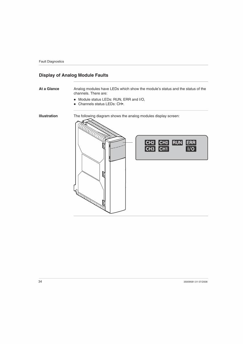
At a Glance Analog modules have LEDs which show the module’s status and the status of the
channels. There are:
Module status LEDs: RUN, ERR and I/O,
Channels status LEDs: CH•.
Illustration The following diagram shows the analog modules display screen:
Fault Diagnostics
35009581.01 07/2008 35
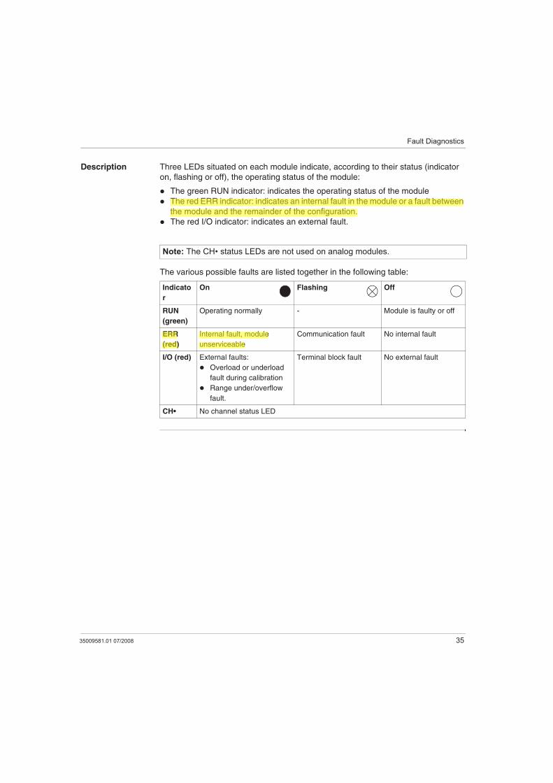
Description Three LEDs situated on each module indicate, according to their status (indicator
on, flashing or off), the operating status of the module:
The green RUN indicator: indicates the operating status of the module
The red ERR indicator: indicates an internal fault in the module or a fault between
the module and the remainder of the configuration.
The red I/O indicator: indicates an external fault.
The various possible faults are listed together in the following table:
Note: The CH• status LEDs are not used on analog modules.
Indicato
r
On Flashing Off
RUN
(green)
Operating normally - Module is faulty or off
ERR
(red)
Internal fault, module
unserviceable
Communication fault No internal fault
I/O (red) External faults:
Overload or underload
fault during calibration
Range under/overflow
fault.
Terminal block fault No external fault
CH• No channel status LED
Fault Diagnostics
36 35009581.01 07/2008
Analog module diagnostics
At a Glance A faulty module makes itself evident by means of lit or flashing RUN, ERR and I/O
LEDs.
Faults are classed in three groups : external errors, internal errors and other faults.
External errors There are two types of external errors which make the I/O LED light up:
Measurement range overrun fault
This fault occurs when the measurement taken on the input line is outside the
user-defined limits.
Sensor link fault (only on TSX AEY 414/1614)
This occurs when there is a connectivity problem between the module and one or
more sensors.
Fault Diagnostics
35009581.01 07/2008 37
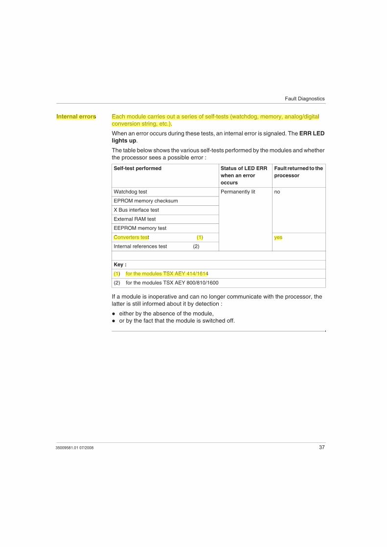
Internal errors Each module carries out a series of self-tests (watchdog, memory, analog/digital
conversion string, etc.).
When an error occurs during these tests, an internal error is signaled. The ERR LED
lights up.
The table below shows the various self-tests performed by the modules and whether
the processor sees a possible error :
If a module is inoperative and can no longer communicate with the processor, the
latter is still informed about it by detection :
either by the absence of the module,
or by the fact that the module is switched off.
Self-test performed Status of LED ERR
when an error
occurs
Fault returned to the
processor
Watchdog test Permanently lit no
EPROM memory checksum
X Bus interface test
External RAM test
EEPROM memory test
Converters test (1) yes
Internal references test (2)
Key :
(1) for the modules TSX AEY 414/1614
(2) for the modules TSX AEY 800/810/1600
Fault Diagnostics
38 35009581.01 07/2008
Other faults The other faults include :
Terminal block fault
The terminal block fault occurs when at least one channel is used whilst the
corresponding Sub-D connector or terminal block is missing.
External supply fault of the outputs (only with the TSX ASY 800)
The output supply fault occurs when an external supply is used to supply the
module TSX ASY 800 and when this supply is detected as missing.
Communication fault
It can be caused by a hardware fault at rack back bus level, by a processor fault
or extension cable fault.
Note: When there is a communication fault with the processor, the channel value
images (at PLC processor level) are frozen at the last value present prior to the
fault.
Fault Diagnostics
35009581.01 07/2008 39
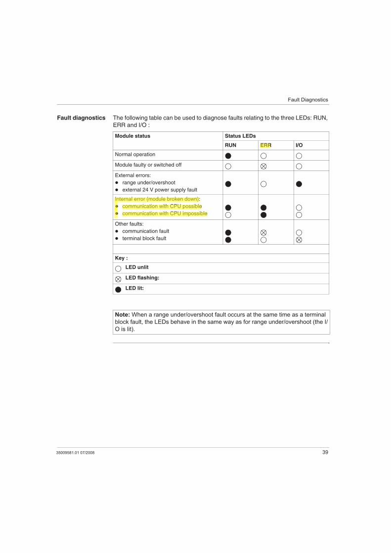
Fault diagnostics The following table can be used to diagnose faults relating to the three LEDs: RUN,
ERR and I/O :
Module status Status LEDs
RUN ERR I/O
Normal operation
Module faulty or switched off
External errors:
range under/overshoot
external 24 V power supply fault
Internal error (module broken down):
communication with CPU possible
communication with CPU impossible
Other faults:
communication fault
terminal block fault
Key :
LED unlit
LED flashing:
LED lit:
Note: When a range under/overshoot fault occurs at the same time as a terminal
block fault, the LEDs behave in the same way as for range under/overshoot (the I/
O is lit).

Fault Diagnostics
40 35009581.01 07/2008
35009581.01 07/2008 41
4Analog Input Module TSX AEY 414
At a Glance
Aim of this
Chapter
This chapter introduces the TSX AEY 414 module, its characteristics and its
connection to different sensors.
What's in this
Chapter?
This chapter contains the following topics:
Topic Page
Introducing the TSX AEY 414 module 42
Characteristics of the TSX AEY 414 Module 43
Detailed Characteristics of TSX AEY 414 Module Inputs 46
Characteristics of the Thermowell Ranges for the TSX AEY 414 53
Characteristics of the TSX AEY 414 Thermocouple Range in Degrees Celsius 55
Characteristics of the TSX AEY 414 Thermocouple Range in Degrees
Fahrenheit
60
TSX AEY 414 Screw Terminal Block TSX BLY 01 64
Connecting Sensors on the TSX AEY 414 65
Recommendations for installing the thermocouples for TSX AEY 414 67
TSX AEY 414
42 35009581.01 07/2008
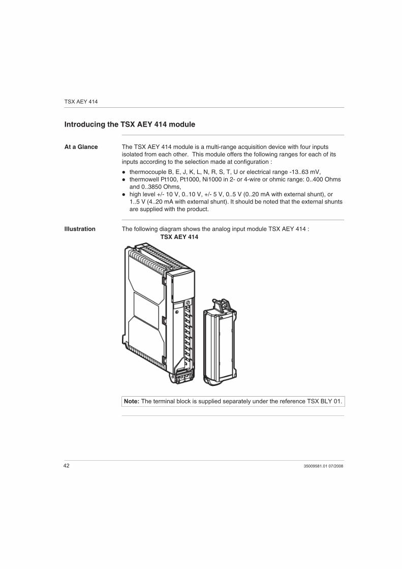
Introducing the TSX AEY 414 module
At a Glance The TSX AEY 414 module is a multi-range acquisition device with four inputs
isolated from each other. This module offers the following ranges for each of its
inputs according to the selection made at configuration :
thermocouple B, E, J, K, L, N, R, S, T, U or electrical range -13..63 mV,
thermowell Pt100, Pt1000, Ni1000 in 2- or 4-wire or ohmic range: 0..400 Ohms
and 0..3850 Ohms,
high level +/- 10 V, 0..10 V, +/- 5 V, 0..5 V (0..20 mA with external shunt), or
1..5 V (4..20 mA with external shunt). It should be noted that the external shunts
are supplied with the product.
Illustration The following diagram shows the analog input module TSX AEY 414 :
Note: The terminal block is supplied separately under the reference TSX BLY 01.
TSX AEY 414
TSX AEY 414
35009581.01 07/2008 43
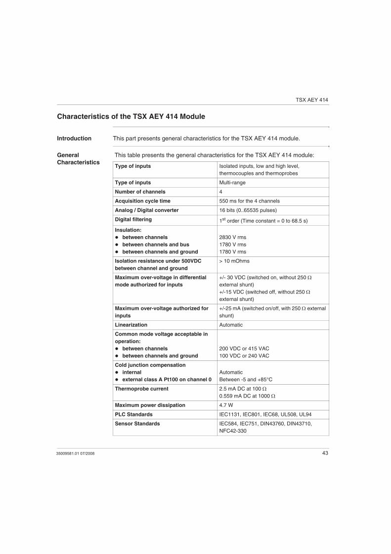
Characteristics of the TSX AEY 414 Module
Introduction This part presents general characteristics for the TSX AEY 414 module.
General
Characteristics
This table presents the general characteristics for the TSX AEY 414 module:
Type of inputs Isolated inputs, low and high level,
thermocouples and thermoprobes
Type of inputs Multi-range
Number of channels 4
Acquisition cycle time 550 ms for the 4 channels
Analog / Digital converter 16 bits (0..65535 pulses)
Digital filtering 1st order (Time constant = 0 to 68.5 s)
Insulation:
between channels
between channels and bus
between channels and ground
2830 V rms
1780 V rms
1780 V rms
Isolation resistance under 500VDC
between channel and ground
> 10 mOhms
Maximum over-voltage in differential
mode authorized for inputs
+/- 30 VDC (switched on, without 250
external shunt)
+/-15 VDC (switched off, without 250
external shunt)
Maximum over-voltage authorized for
inputs
+/-25 mA (switched on/off, with 250 external
shunt)
Linearization Automatic
Common mode voltage acceptable in
operation:
between channels
between channels and ground
200 VDC or 415 VAC
100 VDC or 240 VAC
Cold junction compensation
internal
external class A Pt100 on channel 0
Automatic
Between -5 and +85°C
Thermoprobe current 2.5 mA DC at 100
0.559 mA DC at 1000
Maximum power dissipation 4.7 W
PLC Standards IEC1131, IEC801, IEC68, UL508, UL94
Sensor Standards IEC584, IEC751, DIN43760, DIN43710,
NFC42-330
TSX AEY 414
44 35009581.01 07/2008
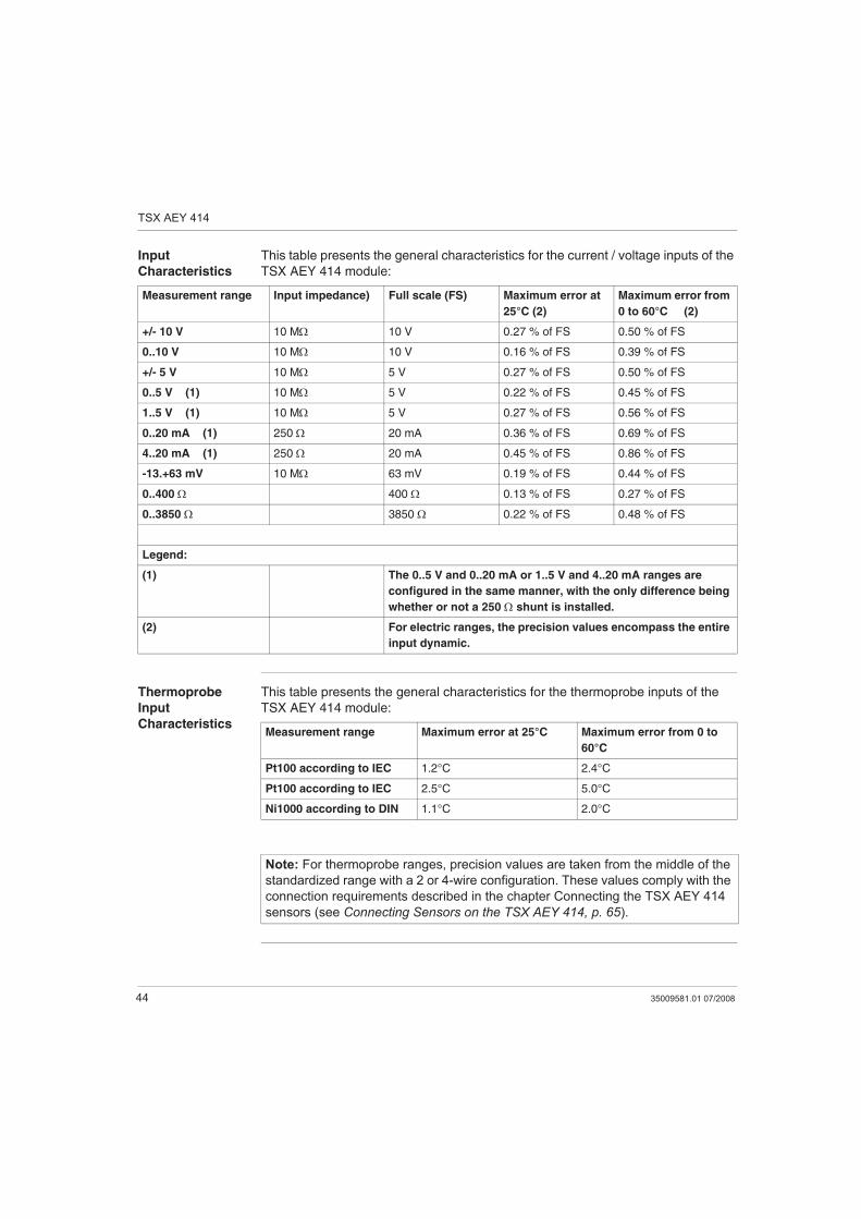
Input
Characteristics
This table presents the general characteristics for the current / voltage inputs of the
TSX AEY 414 module:
Thermoprobe
Input
Characteristics
This table presents the general characteristics for the thermoprobe inputs of the
TSX AEY 414 module:
Measurement range Input impedance) Full scale (FS) Maximum error at
25°C (2)
Maximum error from
0 to 60°C (2)
+/- 10 V 10 M 10 V 0.27 % of FS 0.50 % of FS
0..10 V 10 M 10 V 0.16 % of FS 0.39 % of FS
+/- 5 V 10 M 5 V 0.27 % of FS 0.50 % of FS
0..5 V (1) 10 M 5 V 0.22 % of FS 0.45 % of FS
1..5 V (1) 10 M 5 V 0.27 % of FS 0.56 % of FS
0..20 mA (1) 250 20 mA 0.36 % of FS 0.69 % of FS
4..20 mA (1) 250 20 mA 0.45 % of FS 0.86 % of FS
-13.+63 mV 10 M 63 mV 0.19 % of FS 0.44 % of FS
0..400 400 0.13 % of FS 0.27 % of FS
0..3850 3850 0.22 % of FS 0.48 % of FS
Legend:
(1) The 0..5 V and 0..20 mA or 1..5 V and 4..20 mA ranges are
configured in the same manner, with the only difference being
whether or not a 250 shunt is installed.
(2) For electric ranges, the precision values encompass the entire
input dynamic.
Measurement range Maximum error at 25°C Maximum error from 0 to
60°C
Pt100 according to IEC 1.2°C 2.4°C
Pt100 according to IEC 2.5°C 5.0°C
Ni1000 according to DIN 1.1°C 2.0°C
Note: For thermoprobe ranges, precision values are taken from the middle of the
standardized range with a 2 or 4-wire configuration. These values comply with the
connection requirements described in the chapter Connecting the TSX AEY 414
sensors (see Connecting Sensors on the TSX AEY 414, p. 65).
TSX AEY 414
35009581.01 07/2008 45
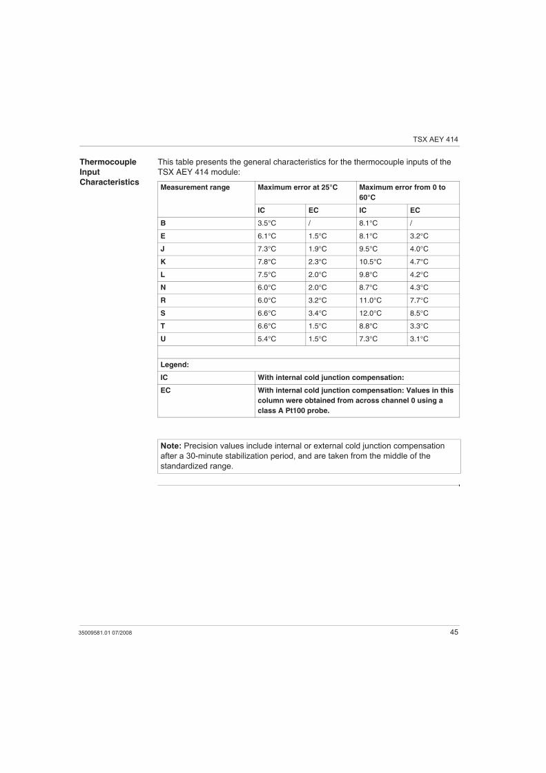
Thermocouple
Input
Characteristics
This table presents the general characteristics for the thermocouple inputs of the
TSX AEY 414 module:
Measurement range Maximum error at 25°C Maximum error from 0 to
60°C
IC EC IC EC
B 3.5°C / 8.1°C /
E 6.1°C 1.5°C 8.1°C 3.2°C
J 7.3°C 1.9°C 9.5°C 4.0°C
K 7.8°C 2.3°C 10.5°C 4.7°C
L 7.5°C 2.0°C 9.8°C 4.2°C
N 6.0°C 2.0°C 8.7°C 4.3°C
R 6.0°C 3.2°C 11.0°C 7.7°C
S 6.6°C 3.4°C 12.0°C 8.5°C
T 6.6°C 1.5°C 8.8°C 3.3°C
U 5.4°C 1.5°C 7.3°C 3.1°C
Legend:
IC With internal cold junction compensation:
EC With internal cold junction compensation: Values in this
column were obtained from across channel 0 using a
class A Pt100 probe.
Note: Precision values include internal or external cold junction compensation
after a 30-minute stabilization period, and are taken from the middle of the
standardized range.
TSX AEY 414
46 35009581.01 07/2008
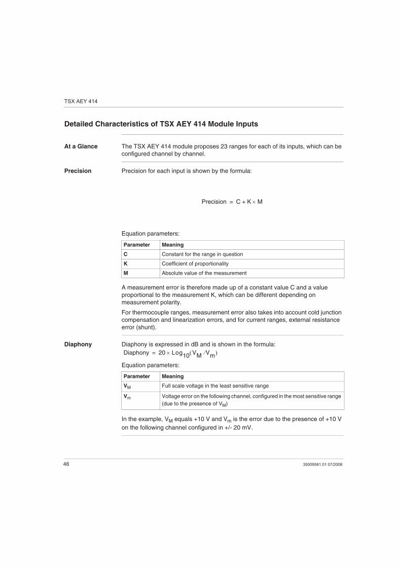
Detailed Characteristics of TSX AEY 414 Module Inputs
At a Glance The TSX AEY 414 module proposes 23 ranges for each of its inputs, which can be
configured channel by channel.
Precision Precision for each input is shown by the formula:
Equation parameters:
A measurement error is therefore made up of a constant value C and a value
proportional to the measurement K, which can be different depending on
measurement polarity.
For thermocouple ranges, measurement error also takes into account cold junction
compensation and linearization errors, and for current ranges, external resistance
error (shunt).
Diaphony Diaphony is expressed in dB and is shown in the formula:
Equation parameters:
In the example, VM equals +10 V and Vm is the error due to the presence of +10 V
on the following channel configured in +/- 20 mV.
Parameter Meaning
C Constant for the range in question
K Coefficient of proportionality
M Absolute value of the measurement
Precision C K M+=
Parameter Meaning
VM Full scale voltage in the least sensitive range
Vm Voltage error on the following channel, configured in the most sensitive range
(due to the presence of VM)
Diaphony 20 Log10
VM
Vm
=
TSX AEY 414
35009581.01 07/2008 47
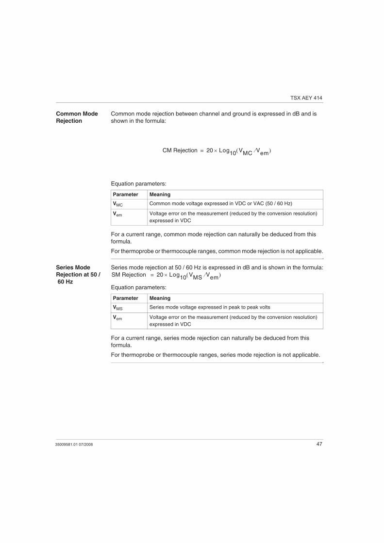
Common Mode
Rejection
Common mode rejection between channel and ground is expressed in dB and is
shown in the formula:
Equation parameters:
For a current range, common mode rejection can naturally be deduced from this
formula.
For thermoprobe or thermocouple ranges, common mode rejection is not applicable.
Series Mode
Rejection at 50 /
60 Hz
Series mode rejection at 50 / 60 Hz is expressed in dB and is shown in the formula:
Equation parameters:
For a current range, series mode rejection can naturally be deduced from this
formula.
For thermoprobe or thermocouple ranges, series mode rejection is not applicable.
Parameter Meaning
VMC Common mode voltage expressed in VDC or VAC (50 / 60 Hz)
Vem Voltage error on the measurement (reduced by the conversion resolution)
expressed in VDC
CM Rejection 20 Log10
VMC
Vem
=
Parameter Meaning
VMS Series mode voltage expressed in peak to peak volts
Vem Voltage error on the measurement (reduced by the conversion resolution)
expressed in VDC
SM Rejection 20 Log10
VMS
Vem
=
TSX AEY 414
48 35009581.01 07/2008
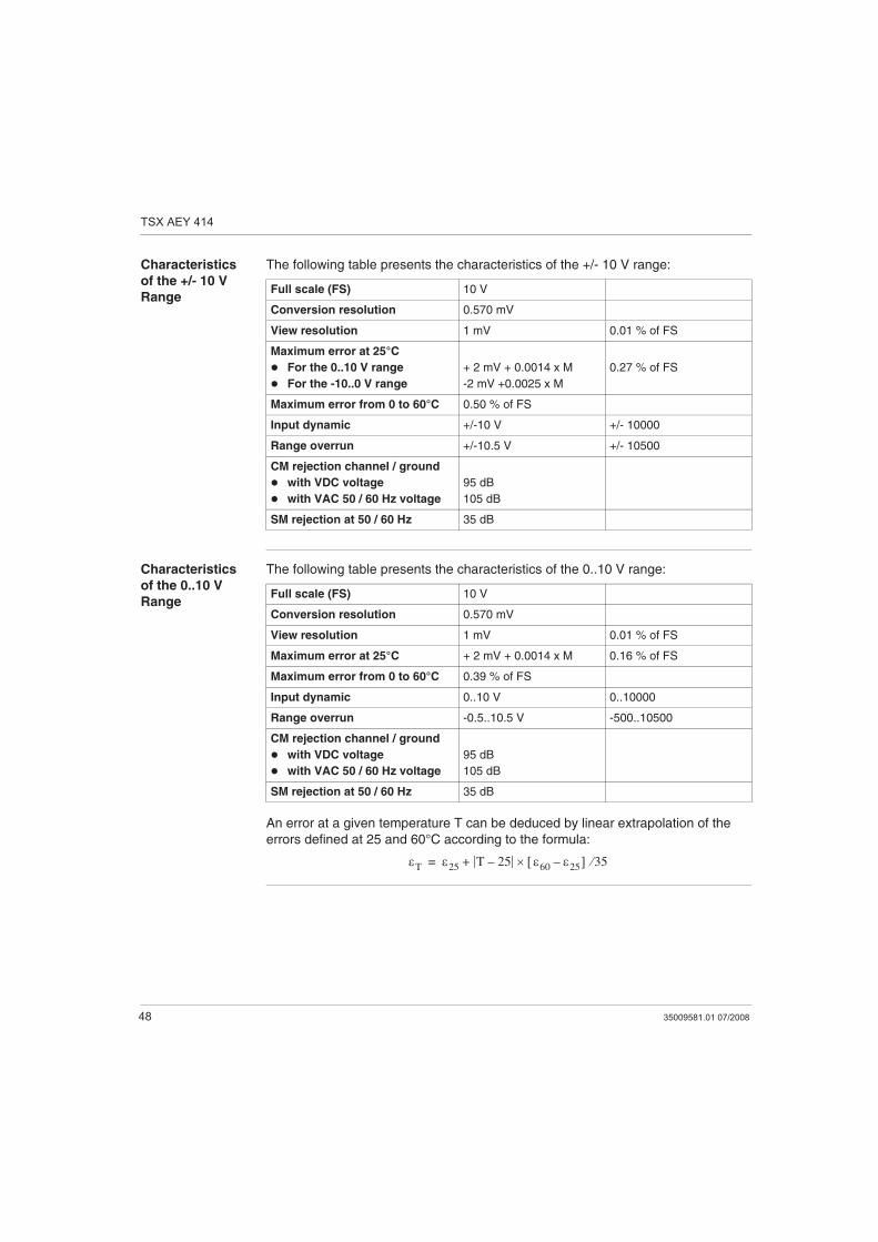
Characteristics
of the +/- 10 V
Range
The following table presents the characteristics of the +/- 10 V range:
Characteristics
of the 0..10 V
Range
The following table presents the characteristics of the 0..10 V range:
An error at a given temperature T can be deduced by linear extrapolation of the
errors defined at 25 and 60°C according to the formula:
Full scale (FS) 10 V
Conversion resolution 0.570 mV
View resolution 1 mV 0.01 % of FS
Maximum error at 25°C
For the 0..10 V range
For the -10..0 V range
+ 2 mV + 0.0014 x M
-2 mV +0.0025 x M
0.27 % of FS
Maximum error from 0 to 60°C 0.50 % of FS
Input dynamic +/-10 V +/- 10000
Range overrun +/-10.5 V +/- 10500
CM rejection channel / ground
with VDC voltage
with VAC 50 / 60 Hz voltage
95 dB
105 dB
SM rejection at 50 / 60 Hz 35 dB
Full scale (FS) 10 V
Conversion resolution 0.570 mV
View resolution 1 mV 0.01 % of FS
Maximum error at 25°C + 2 mV + 0.0014 x M 0.16 % of FS
Maximum error from 0 to 60°C 0.39 % of FS
Input dynamic 0..10 V 0..10000
Range overrun -0.5..10.5 V -500..10500
CM rejection channel / ground
with VDC voltage
with VAC 50 / 60 Hz voltage
95 dB
105 dB
SM rejection at 50 / 60 Hz 35 dB
T 25T 25–
60 25– 35+=
TSX AEY 414
35009581.01 07/2008 49
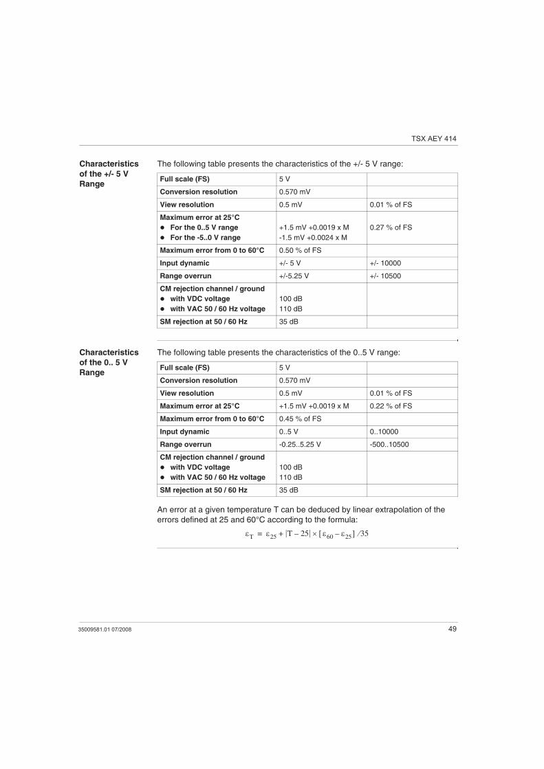
Characteristics
of the +/- 5 V
Range
The following table presents the characteristics of the +/- 5 V range:
Characteristics
of the 0.. 5 V
Range
The following table presents the characteristics of the 0..5 V range:
An error at a given temperature T can be deduced by linear extrapolation of the
errors defined at 25 and 60°C according to the formula:
Full scale (FS) 5 V
Conversion resolution 0.570 mV
View resolution 0.5 mV 0.01 % of FS
Maximum error at 25°C
For the 0..5 V range
For the -5..0 V range
+1.5 mV +0.0019 x M
-1.5 mV +0.0024 x M
0.27 % of FS
Maximum error from 0 to 60°C 0.50 % of FS
Input dynamic +/- 5 V +/- 10000
Range overrun +/-5.25 V +/- 10500
CM rejection channel / ground
with VDC voltage
with VAC 50 / 60 Hz voltage
100 dB
110 dB
SM rejection at 50 / 60 Hz 35 dB
Full scale (FS) 5 V
Conversion resolution 0.570 mV
View resolution 0.5 mV 0.01 % of FS
Maximum error at 25°C +1.5 mV +0.0019 x M 0.22 % of FS
Maximum error from 0 to 60°C 0.45 % of FS
Input dynamic 0..5 V 0..10000
Range overrun -0.25..5.25 V -500..10500
CM rejection channel / ground
with VDC voltage
with VAC 50 / 60 Hz voltage
100 dB
110 dB
SM rejection at 50 / 60 Hz 35 dB
T 25T 25–
60 25– 35+=
TSX AEY 414
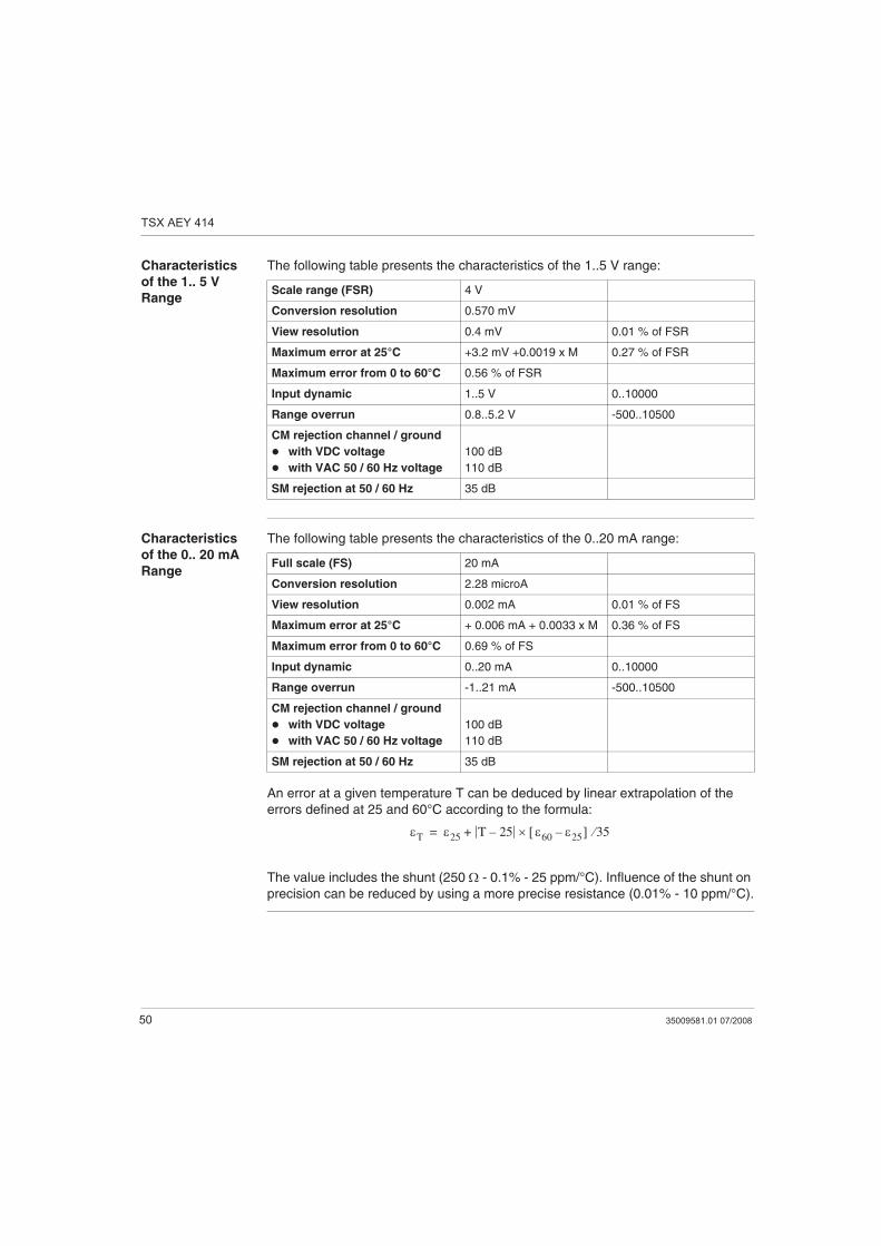
50 35009581.01 07/2008
Characteristics
of the 1.. 5 V
Range
The following table presents the characteristics of the 1..5 V range:
Characteristics
of the 0.. 20 mA
Range
The following table presents the characteristics of the 0..20 mA range:
An error at a given temperature T can be deduced by linear extrapolation of the
errors defined at 25 and 60°C according to the formula:
The value includes the shunt (250 - 0.1% - 25 ppm/°C). Influence of the shunt on
precision can be reduced by using a more precise resistance (0.01% - 10 ppm/°C).
Scale range (FSR) 4 V
Conversion resolution 0.570 mV
View resolution 0.4 mV 0.01 % of FSR
Maximum error at 25°C +3.2 mV +0.0019 x M 0.27 % of FSR
Maximum error from 0 to 60°C 0.56 % of FSR
Input dynamic 1..5 V 0..10000
Range overrun 0.8..5.2 V -500..10500
CM rejection channel / ground
with VDC voltage
with VAC 50 / 60 Hz voltage
100 dB
110 dB
SM rejection at 50 / 60 Hz 35 dB
Full scale (FS) 20 mA
Conversion resolution 2.28 microA
View resolution 0.002 mA 0.01 % of FS
Maximum error at 25°C + 0.006 mA + 0.0033 x M 0.36 % of FS
Maximum error from 0 to 60°C 0.69 % of FS
Input dynamic 0..20 mA 0..10000
Range overrun -1..21 mA -500..10500
CM rejection channel / ground
with VDC voltage
with VAC 50 / 60 Hz voltage
100 dB
110 dB
SM rejection at 50 / 60 Hz 35 dB
T 25T 25–
60 25– 35+=
TSX AEY 414
35009581.01 07/2008 51
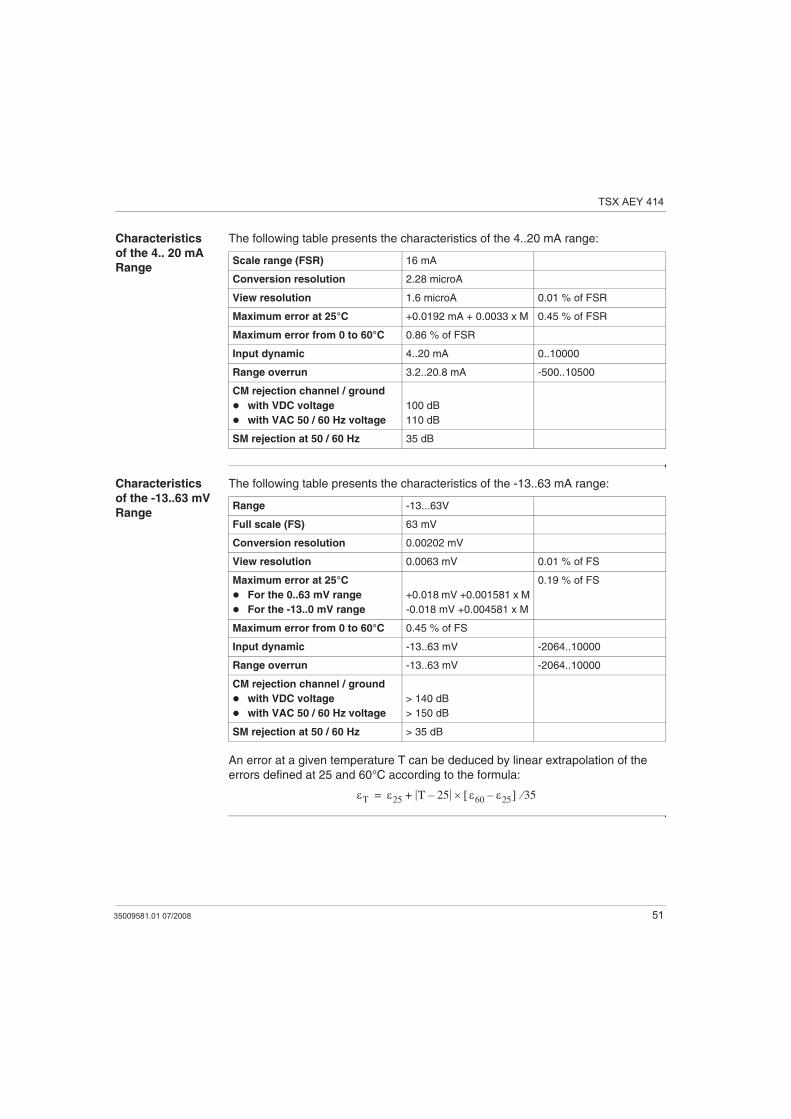
Characteristics
of the 4.. 20 mA
Range
The following table presents the characteristics of the 4..20 mA range:
Characteristics
of the -13..63 mV
Range
The following table presents the characteristics of the -13..63 mA range:
An error at a given temperature T can be deduced by linear extrapolation of the
errors defined at 25 and 60°C according to the formula:
Scale range (FSR) 16 mA
Conversion resolution 2.28 microA
View resolution 1.6 microA 0.01 % of FSR
Maximum error at 25°C +0.0192 mA + 0.0033 x M 0.45 % of FSR
Maximum error from 0 to 60°C 0.86 % of FSR
Input dynamic 4..20 mA 0..10000
Range overrun 3.2..20.8 mA -500..10500
CM rejection channel / ground
with VDC voltage
with VAC 50 / 60 Hz voltage
100 dB
110 dB
SM rejection at 50 / 60 Hz 35 dB
Range -13...63V
Full scale (FS) 63 mV
Conversion resolution 0.00202 mV
View resolution 0.0063 mV 0.01 % of FS
Maximum error at 25°C
For the 0..63 mV range
For the -13..0 mV range
+0.018 mV +0.001581 x M
-0.018 mV +0.004581 x M
0.19 % of FS
Maximum error from 0 to 60°C 0.45 % of FS
Input dynamic -13..63 mV -2064..10000
Range overrun -13..63 mV -2064..10000
CM rejection channel / ground
with VDC voltage
with VAC 50 / 60 Hz voltage
> 140 dB
> 150 dB
SM rejection at 50 / 60 Hz > 35 dB
T 25T 25–
60 25– 35+=
TSX AEY 414
52 35009581.01 07/2008
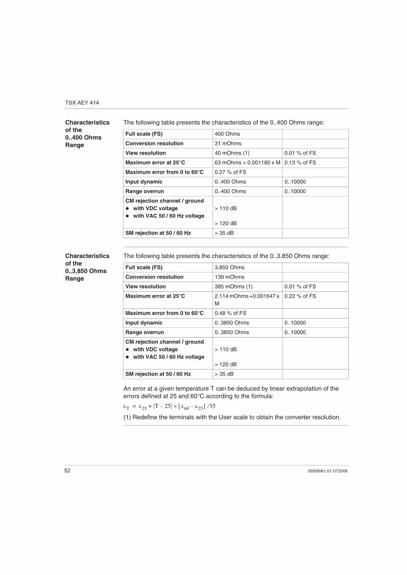
Characteristics
of the
0..400 Ohms
Range
The following table presents the characteristics of the 0..400 Ohms range:
Characteristics
of the
0..3,850 Ohms
Range
The following table presents the characteristics of the 0..3,850 Ohms range:
An error at a given temperature T can be deduced by linear extrapolation of the
errors defined at 25 and 60°C according to the formula:
(1) Redefine the terminals with the User scale to obtain the converter resolution.
Full scale (FS) 400 Ohms
Conversion resolution 31 mOhms
View resolution 40 mOhms (1) 0.01 % of FS
Maximum error at 25°C 63 mOhms + 0.001180 x M 0.13 % of FS
Maximum error from 0 to 60°C 0.27 % of FS
Input dynamic 0..400 Ohms 0..10000
Range overrun 0..400 Ohms 0..10000
CM rejection channel / ground
with VDC voltage
with VAC 50 / 60 Hz voltage
> 110 dB
> 120 dB
SM rejection at 50 / 60 Hz > 35 dB
Full scale (FS) 3,850 Ohms
Conversion resolution 139 mOhms
View resolution 385 mOhms (1) 0.01 % of FS
Maximum error at 25°C 2.114 mOhms +0.001647 x
M
0.22 % of FS
Maximum error from 0 to 60°C 0.48 % of FS
Input dynamic 0..3850 Ohms 0..10000
Range overrun 0..3850 Ohms 0..10000
CM rejection channel / ground
with VDC voltage
with VAC 50 / 60 Hz voltage
> 110 dB
> 120 dB
SM rejection at 50 / 60 Hz > 35 dB
T 25T 25–
60 25– 35+=
TSX AEY 414
35009581.01 07/2008 53
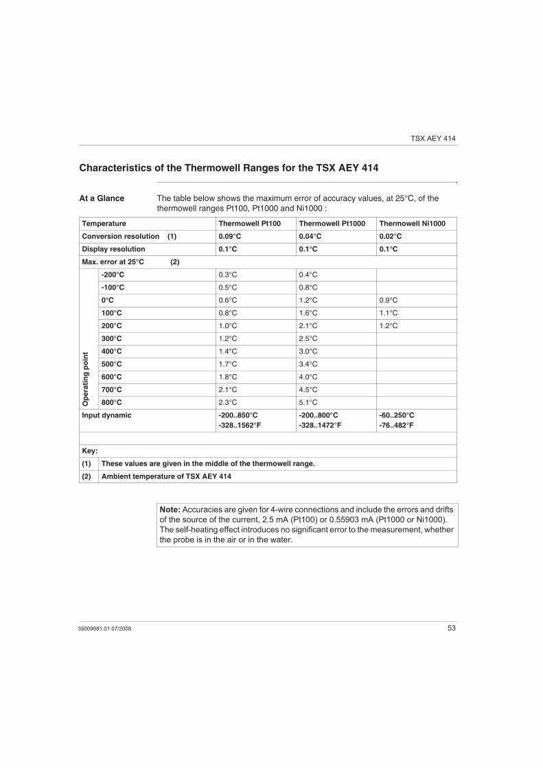
Characteristics of the Thermowell Ranges for the TSX AEY 414
At a Glance The table below shows the maximum error of accuracy values, at 25°C, of the
thermowell ranges Pt100, Pt1000 and Ni1000 :
Temperature Thermowell Pt100 Thermowell Pt1000 Thermowell Ni1000
Conversion resolution (1) 0.09°C 0.04°C 0.02°C
Display resolution 0.1°C 0.1°C 0.1°C
Max. error at 25°C (2)
Op
era
tin
g p
oin
t
-200°C 0.3°C 0.4°C
-100°C 0.5°C 0.8°C
0°C 0.6°C 1.2°C 0.9°C
100°C 0.8°C 1.6°C 1.1°C
200°C 1.0°C 2.1°C 1.2°C
300°C 1.2°C 2.5°C
400°C 1.4°C 3.0°C
500°C 1.7°C 3.4°C
600°C 1.8°C 4.0°C
700°C 2.1°C 4.5°C
800°C 2.3°C 5.1°C
Input dynamic -200..850°C
-328..1562°F
-200..800°C
-328..1472°F
-60..250°C
-76..482°F
Key:
(1) These values are given in the middle of the thermowell range.
(2) Ambient temperature of TSX AEY 414
Note: Accuracies are given for 4-wire connections and include the errors and drifts
of the source of the current, 2.5 mA (Pt100) or 0.55903 mA (Pt1000 or Ni1000).
The self-heating effect introduces no significant error to the measurement, whether
the probe is in the air or in the water.
TSX AEY 414
54 35009581.01 07/2008
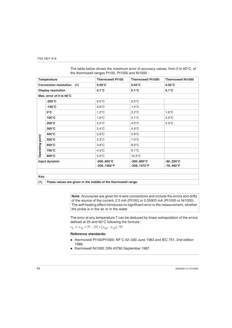
The table below shows the maximum error of accuracy values, from 0 to 60°C, of
the thermowell ranges Pt100, Pt1000 and Ni1000 :
The error at any temperature T can be deduced by linear extrapolation of the errors
defined at 25 and 60°C following the formula :
Reference standards:
thermowell Pt100/Pt1000: NF C 42–330 June 1983 and IEC 751, 2nd edition
1986,
thermowell Ni1000: DIN 43760 September 1987.
Temperature Thermowell Pt100 Thermowell Pt1000 Thermowell Ni1000
Conversion resolution (1) 0.09°C 0.04°C 0.02°C
Display resolution 0.1°C 0.1°C 0.1°C
Max. error of 0 to 60°C
Op
era
tin
g p
oin
t
-200°C 0.5°C 0.5°C
-100°C 0.8°C 1.4°C
0°C 1.2°C 2.2°C 1.6°C
100°C 1.6°C 3.1°C 2.0°C
200°C 2.0°C 4.0°C 2.3°C
300°C 2.4°C 4.9°C
400°C 2.9°C 5.9°C
500°C 3.3°C 7.0°C
600°C 3.8°C 8.0°C
700°C 4.4°C 9.1°C
800°C 5.0°C 10.3°C
Input dynamic -200..850°C
-328..1562°F
-200..800°C
-328..1472°F
-60..250°C
-76..482°F
Key:
(1) These values are given in the middle of the thermowell range.
Note: Accuracies are given for 4-wire connections and include the errors and drifts
of the source of the current, 2.5 mA (Pt100) or 0.55903 mA (Pt1000 or Ni1000).
The self-heating effect introduces no significant error to the measurement, whether
the probe is in the air or in the water.
T 25T 25–
60 25– 35+=
TSX AEY 414
35009581.01 07/2008 55
Characteristics of the TSX AEY 414 Thermocouple Range in Degrees Celsius
At a Glance The following tables show the measuring chain errors for the different
thermocouples B, E, J, K, N, R, S and T in degrees Celsius. These values take into
account:
The values given below are valid regardless of the type of cold junction
compensation: TELEFAST or Pt100 class A.
The cold junction temperature considered in the precision calculation is 25°C.
The resolution is given with a mid-range operating point.
The values include: electrical errors on the acquisition system for input channels
and cold junction compensation, software errors and interchangeability errors on
the cold junction compensation sensors. Thermocouple sensor errors are not
taken into account.
TSX AEY 414
56 35009581.01 07/2008
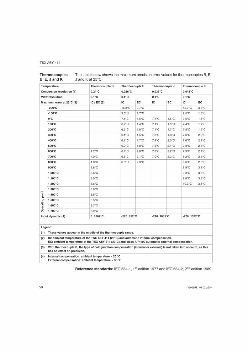
Thermocouples
B, E, J and K
The table below shows the maximum precision error values for thermocouples B, E,
J and K at 25°C.
Reference standards: IEC 584-1, 1st edition 1977 and IEC 584-2, 2nd edition 1989.
Temperature Thermocouple B Thermocouple E Thermocouple J Thermocouple K
Conversion resolution (1) 0.24°C 0.026°C 0.037°C 0.048°C
View resolution 0.1°C 0.1°C 0.1°C 0.1°C
Maximum error at 25°C (2) IC / EC (3) IC EC IC EC IC EC
Op
era
tin
g p
oin
t
-200°C 16.8°C 2.7°C 18.7°C 3.3°C
-100°C 9.5°C 1.7°C 9.5°C 1.8°C
0°C 7.5°C 1.5°C 7.4°C 1.5°C 7.5°C 1.6°C
100°C 6.7°C 1.4°C 7.1°C 1.5°C 7.4°C 1.7°C
200°C 6.2°C 1.5°C 7.1°C 1.7°C 7.8°C 1.9°C
300°C 6.1°C 1.5°C 7.3°C 1.8°C 7.6°C 2.0°C
400°C 6.1°C 1.7°C 7.4°C 2.0°C 7.6°C 2.1°C
500°C 6.2°C 1.8°C 7.5°C 2.1°C 7.8°C 2.3°C
600°C 4.7°C 6.4°C 2.0°C 7.3°C 2.2°C 7.9°C 2.4°C
700°C 4.0°C 6.6°C 2.1°C 7.0°C 2.2°C 8.2°C 2.6°C
800°C 4.0°C 6.8°C 2.3°C 8.6°C 2.8°C
900°C 3.8°C 8.9°C 3.1°C
1,000°C 3.6°C 9.3°C 3.3°C
1,100°C 3.5°C 9.8°C 3.6°C
1,200°C 3.6°C 10.3°C 3.8°C
1,300°C 3.6°C
1,400°C 3.5°C
1,500°C 3.5°C
1,600°C 3.7°C
1,700°C 3.9°C
Input dynamic (4) 0..1802°C -270..812°C -210..1065°C -270..1372°C
Legend:
(1) These values appear in the middle of the thermocouple range.
(2) IC: ambient temperature of the TSX AEY 414 (20°C) and automatic internal compensation.
EC: ambient temperature of the TSX AEY 414 (30°C) and class A Pt100 automatic external compensation.
(3) With thermocouple B, the type of cold junction compensation (internal or external) is not taken into account, as this
has no effect on precision.
(4) Internal compensation: ambient temperature = 20 °C
External compensation: ambient temperature = 30 °C.
TSX AEY 414
35009581.01 07/2008 57
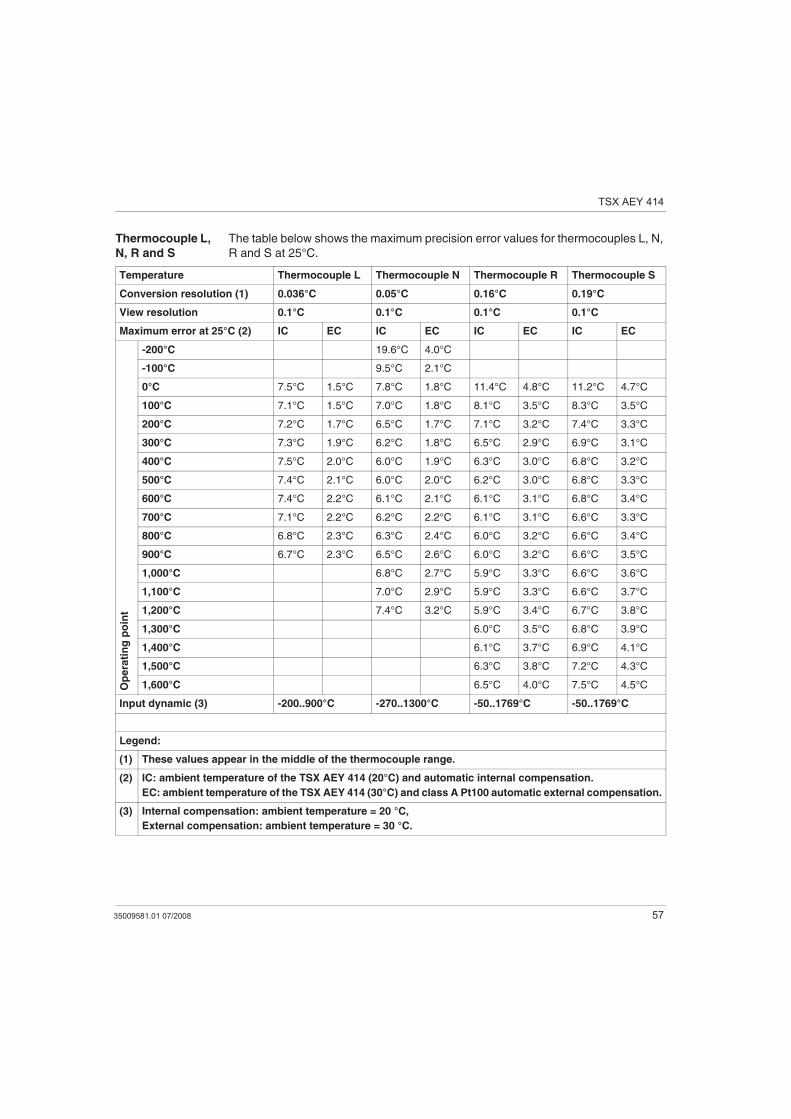
Thermocouple L,
N, R and S
The table below shows the maximum precision error values for thermocouples L, N,
R and S at 25°C.
Temperature Thermocouple L Thermocouple N Thermocouple R Thermocouple S
Conversion resolution (1) 0.036°C 0.05°C 0.16°C 0.19°C
View resolution 0.1°C 0.1°C 0.1°C 0.1°C
Maximum error at 25°C (2) IC EC IC EC IC EC IC EC
Op
era
tin
g p
oin
t
-200°C 19.6°C 4.0°C
-100°C 9.5°C 2.1°C
0°C 7.5°C 1.5°C 7.8°C 1.8°C 11.4°C 4.8°C 11.2°C 4.7°C
100°C 7.1°C 1.5°C 7.0°C 1.8°C 8.1°C 3.5°C 8.3°C 3.5°C
200°C 7.2°C 1.7°C 6.5°C 1.7°C 7.1°C 3.2°C 7.4°C 3.3°C
300°C 7.3°C 1.9°C 6.2°C 1.8°C 6.5°C 2.9°C 6.9°C 3.1°C
400°C 7.5°C 2.0°C 6.0°C 1.9°C 6.3°C 3.0°C 6.8°C 3.2°C
500°C 7.4°C 2.1°C 6.0°C 2.0°C 6.2°C 3.0°C 6.8°C 3.3°C
600°C 7.4°C 2.2°C 6.1°C 2.1°C 6.1°C 3.1°C 6.8°C 3.4°C
700°C 7.1°C 2.2°C 6.2°C 2.2°C 6.1°C 3.1°C 6.6°C 3.3°C
800°C 6.8°C 2.3°C 6.3°C 2.4°C 6.0°C 3.2°C 6.6°C 3.4°C
900°C 6.7°C 2.3°C 6.5°C 2.6°C 6.0°C 3.2°C 6.6°C 3.5°C
1,000°C 6.8°C 2.7°C 5.9°C 3.3°C 6.6°C 3.6°C
1,100°C 7.0°C 2.9°C 5.9°C 3.3°C 6.6°C 3.7°C
1,200°C 7.4°C 3.2°C 5.9°C 3.4°C 6.7°C 3.8°C
1,300°C 6.0°C 3.5°C 6.8°C 3.9°C
1,400°C 6.1°C 3.7°C 6.9°C 4.1°C
1,500°C 6.3°C 3.8°C 7.2°C 4.3°C
1,600°C 6.5°C 4.0°C 7.5°C 4.5°C
Input dynamic (3) -200..900°C -270..1300°C -50..1769°C -50..1769°C
Legend:
(1) These values appear in the middle of the thermocouple range.
(2) IC: ambient temperature of the TSX AEY 414 (20°C) and automatic internal compensation.
EC: ambient temperature of the TSX AEY 414 (30°C) and class A Pt100 automatic external compensation.
(3) Internal compensation: ambient temperature = 20 °C,
External compensation: ambient temperature = 30 °C.
TSX AEY 414
58 35009581.01 07/2008
Reference standards:
Thermocouple L: DIN 43710, December 1985 edition
Thermocouple N: IEC 584-1, 2nd edition 1989 and IEC 584-2, 2nd edition 1989,
Thermocouple R: IEC 584-1, 1st edition 1977 and IEC 584-2, 2nd edition 1989,
Thermocouple S: IEC 584-1, 1st edition 1977 and IEC 584-2, 2nd edition 1989.
TSX AEY 414
35009581.01 07/2008 59
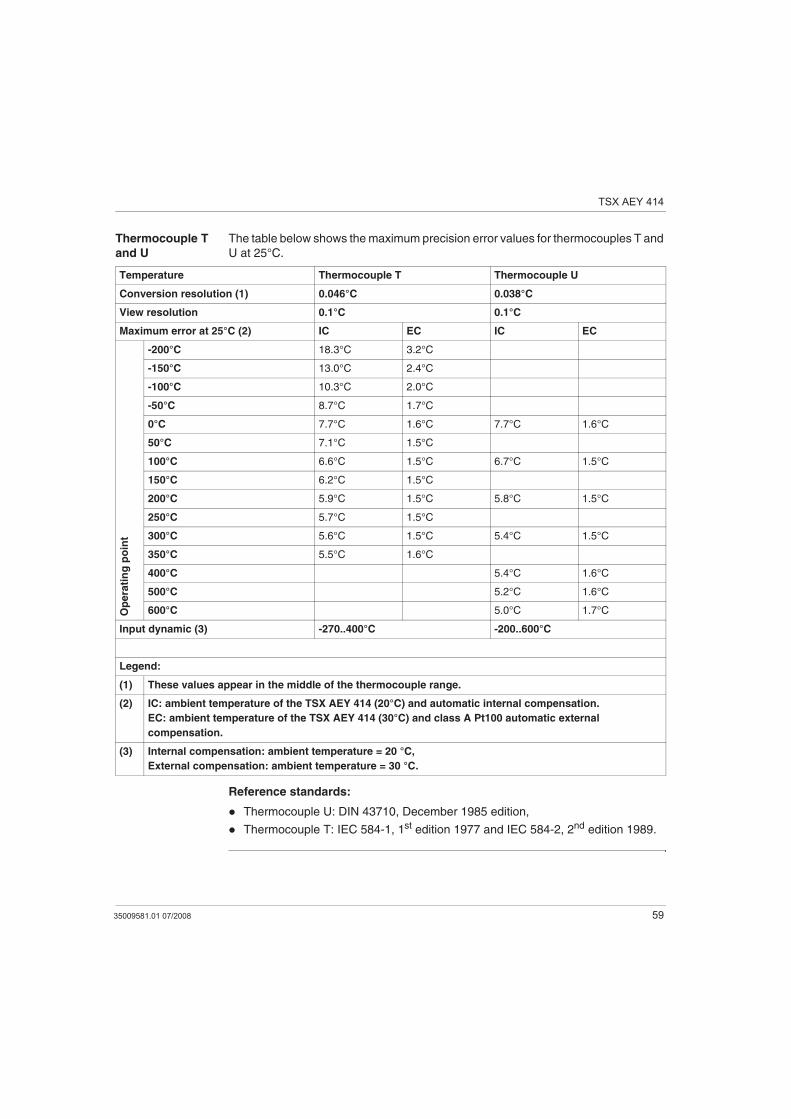
Thermocouple T
and U
The table below shows the maximum precision error values for thermocouples T and
U at 25°C.
Reference standards:
Thermocouple U: DIN 43710, December 1985 edition,
Thermocouple T: IEC 584-1, 1st edition 1977 and IEC 584-2, 2nd edition 1989.
Temperature Thermocouple T Thermocouple U
Conversion resolution (1) 0.046°C 0.038°C
View resolution 0.1°C 0.1°C
Maximum error at 25°C (2) IC EC IC EC
Op
era
tin
g p
oin
t
-200°C 18.3°C 3.2°C
-150°C 13.0°C 2.4°C
-100°C 10.3°C 2.0°C
-50°C 8.7°C 1.7°C
0°C 7.7°C 1.6°C 7.7°C 1.6°C
50°C 7.1°C 1.5°C
100°C 6.6°C 1.5°C 6.7°C 1.5°C
150°C 6.2°C 1.5°C
200°C 5.9°C 1.5°C 5.8°C 1.5°C
250°C 5.7°C 1.5°C
300°C 5.6°C 1.5°C 5.4°C 1.5°C
350°C 5.5°C 1.6°C
400°C 5.4°C 1.6°C
500°C 5.2°C 1.6°C
600°C 5.0°C 1.7°C
Input dynamic (3) -270..400°C -200..600°C
Legend:
(1) These values appear in the middle of the thermocouple range.
(2) IC: ambient temperature of the TSX AEY 414 (20°C) and automatic internal compensation.
EC: ambient temperature of the TSX AEY 414 (30°C) and class A Pt100 automatic external
compensation.
(3) Internal compensation: ambient temperature = 20 °C,
External compensation: ambient temperature = 30 °C.
TSX AEY 414
60 35009581.01 07/2008
Characteristics of the TSX AEY 414 Thermocouple Range in Degrees Fahrenheit
At a Glance The following tables show the errors of the measuring chain for the different
thermocouples B, E, J, K, N, R, S and T in degrees Fahrenheit. These values take
into account:
The precision values given below are valid regardless of the type of cold junction
compensation: TELEFAST or Pt100 class A.
The cold junction temperature considered in the precision calculation is 77°F.
The resolution is given with a mid-range operating point.
The precision values include: electrical errors on the acquisition system for input
channels and cold junction compensation, software errors and interchangeability
errors on the cold junction compensation sensors. Thermocouple sensor errors
are not taken into account.
TSX AEY 414
35009581.01 07/2008 61
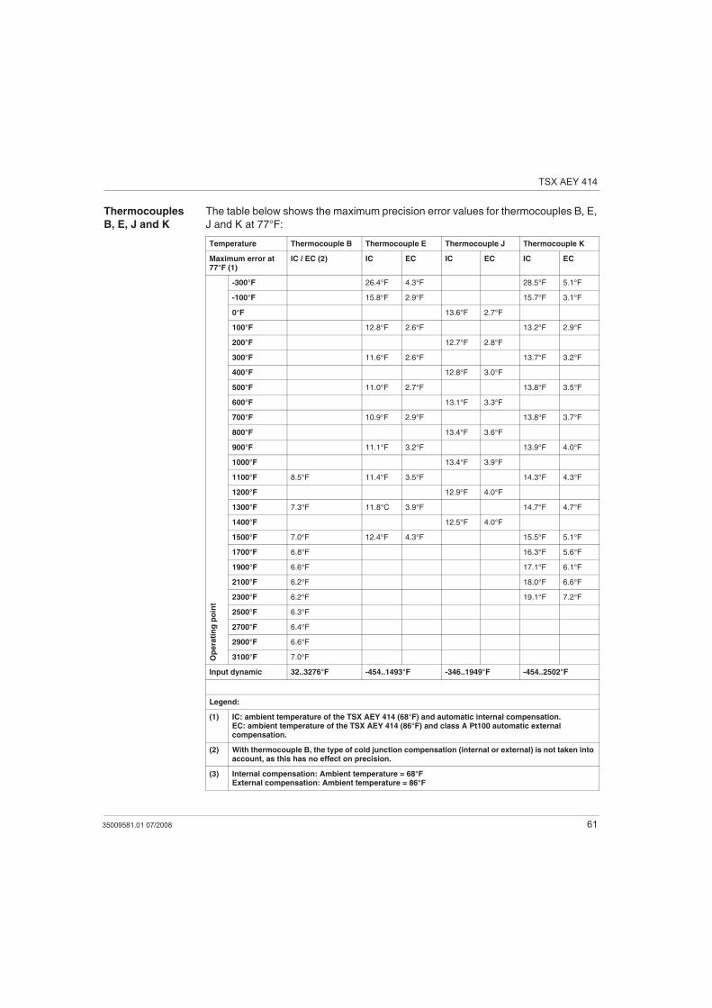
Thermocouples
B, E, J and K
The table below shows the maximum precision error values for thermocouples B, E,
J and K at 77°F:
Temperature Thermocouple B Thermocouple E Thermocouple J Thermocouple K
Maximum error at 77°F (1)
IC / EC (2) IC EC IC EC IC EC
Op
era
tin
g p
oin
t
-300°F 26.4°F 4.3°F 28.5°F 5.1°F
-100°F 15.8°F 2.9°F 15.7°F 3.1°F
0°F 13.6°F 2.7°F
100°F 12.8°F 2.6°F 13.2°F 2.9°F
200°F 12.7°F 2.8°F
300°F 11.6°F 2.6°F 13.7°F 3.2°F
400°F 12.8°F 3.0°F
500°F 11.0°F 2.7°F 13.8°F 3.5°F
600°F 13.1°F 3.3°F
700°F 10.9°F 2.9°F 13.8°F 3.7°F
800°F 13.4°F 3.6°F
900°F 11.1°F 3.2°F 13.9°F 4.0°F
1000°F 13.4°F 3.9°F
1100°F 8.5°F 11.4°F 3.5°F 14.3°F 4.3°F
1200°F 12.9°F 4.0°F
1300°F 7.3°F 11.8°C 3.9°F 14.7°F 4.7°F
1400°F 12.5°F 4.0°F
1500°F 7.0°F 12.4°F 4.3°F 15.5°F 5.1°F
1700°F 6.8°F 16.3°F 5.6°F
1900°F 6.6°F 17.1°F 6.1°F
2100°F 6.2°F 18.0°F 6.6°F
2300°F 6.2°F 19.1°F 7.2°F
2500°F 6.3°F
2700°F 6.4°F
2900°F 6.6°F
3100°F 7.0°F
Input dynamic 32..3276°F -454..1493°F -346..1949°F -454..2502°F
Legend:
(1) IC: ambient temperature of the TSX AEY 414 (68°F) and automatic internal compensation.EC: ambient temperature of the TSX AEY 414 (86°F) and class A Pt100 automatic external compensation.
(2) With thermocouple B, the type of cold junction compensation (internal or external) is not taken into account, as this has no effect on precision.
(3) Internal compensation: Ambient temperature = 68°FExternal compensation: Ambient temperature = 86°F
TSX AEY 414
62 35009581.01 07/2008
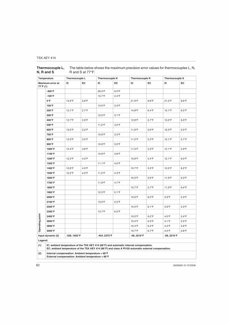
Thermocouple L,
N, R and S
The table below shows the maximum precision error values for thermocouples L, N,
R and S at 77°F:
Temperature Thermocouple L Thermocouple N Thermocouple R Thermocouple S
Maximum error at
77°F (1)
IC EC IC EC IC EC IC EC
Op
era
tin
g p
oin
t
-300°F 29.4°F 6.0°F
-100°F 15.7°F 3.4°F
0°F 14.9°F 2.8°F 21.9°F 8.8°F 21.2°F 8.6°F
100°F 13.5°F 3.3°F
200°F 13.1°F 2.7°F 14.8°F 6.4°F 15.1°F 6.5°F
300°F 12.0°F 3.1°F
400°F 12.7°F 2.9°F 12.8°F 5.7°F 13.3°F 6.0°F
500°F 11.2°F 3.2°F
600°F 13.0°F 3.2°F 11.9°F 5.6°F 12.3°F 5.5°F
700°F 10.9°F 3.3°F
800°F 13.3°F 3.5°F 11.2°F 5.3°F 12.1°F 5.7°F
900°F 10.9°F 3.5°F
1000°F 12.4°F 3.8°F 11.0°F 5.3°F 12.1°F 5.9°F
1100°F 10.9°F 3.8°F
1200°F 12.3°F 4.0°F 10.8°F 5.4°F 12.1°F 6.0°F
1300°F 11.1°F 4.0°F
1400°F 12.8°F 4.0°F 10.7°F 5.5°F 12.0°F 6.2°F
1500°F 12.2°F 4.0°F 11.5°F 4.3°F
1600°F 10.5°F 5.6°F 11.9°F 6.3°F
1700°F 11.9°F 4.7°F
1800°F 10.7°F 5.7°F 11.9°F 6.4°F
1900°F 12.3°F 5.1°F
2000°F 10.6°F 6.0°F 3.9°F 2.3°F
2100°F 13.0°F 5.5°F
2200°F 10.5°F 6.1°F 3.9°F 2.3°F
2300°F 13.7°F 6.0°F
2400°F 10.5°F 6.2°F 4.0°F 2.4°F
2600°F 10.4°F 6.3°F 4.1°F 2.5°F
2800°F 10.4°F 6.4°F 4.2°F 2.6°F
3000°F 10.7°F 6.7°F 4.4°F 2.8°F
Input dynamic (2) -328..1652°F -454..2372°F -58..3216°F -58..3216°F
Legend:
(1) IC: ambient temperature of the TSX AEY 414 (68°F) and automatic internal compensation.
EC: ambient temperature of the TSX AEY 414 (86°F) and class A Pt100 automatic external compensation.
(2) Internal compensation: Ambient temperature = 68°F
External compensation: Ambient temperature = 86°F
TSX AEY 414
35009581.01 07/2008 63
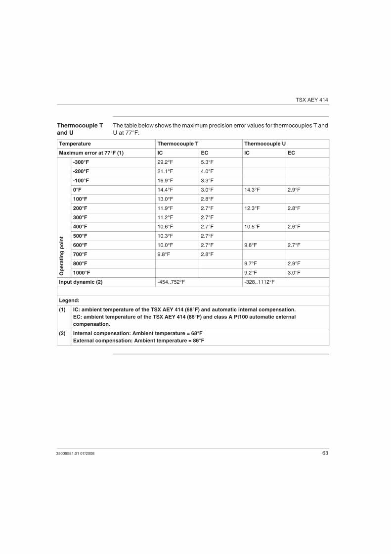
Thermocouple T
and U
The table below shows the maximum precision error values for thermocouples T and
U at 77°F:
Temperature Thermocouple T Thermocouple U
Maximum error at 77°F (1) IC EC IC EC
Op
era
tin
g p
oin
t
-300°F 29.2°F 5.3°F
-200°F 21.1°F 4.0°F
-100°F 16.9°F 3.3°F
0°F 14.4°F 3.0°F 14.3°F 2.9°F
100°F 13.0°F 2.8°F
200°F 11.9°F 2.7°F 12.3°F 2.8°F
300°F 11.2°F 2.7°F
400°F 10.6°F 2.7°F 10.5°F 2.6°F
500°F 10.3°F 2.7°F
600°F 10.0°F 2.7°F 9.8°F 2.7°F
700°F 9.8°F 2.8°F
800°F 9.7°F 2.9°F
1000°F 9.2°F 3.0°F
Input dynamic (2) -454..752°F -328..1112°F
Legend:
(1) IC: ambient temperature of the TSX AEY 414 (68°F) and automatic internal compensation.
EC: ambient temperature of the TSX AEY 414 (86°F) and class A Pt100 automatic external
compensation.
(2) Internal compensation: Ambient temperature = 68°F
External compensation: Ambient temperature = 86°F
TSX AEY 414
64 35009581.01 07/2008
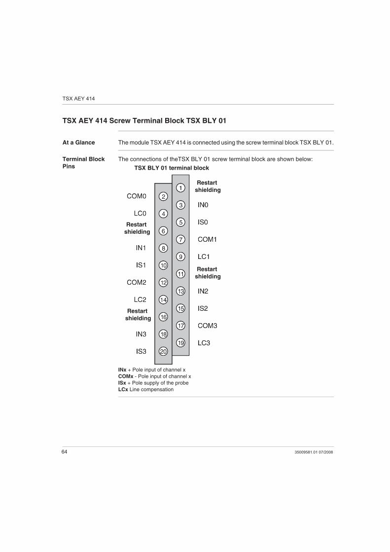
TSX AEY 414 Screw Terminal Block TSX BLY 01
At a Glance The module TSX AEY 414 is connected using the screw terminal block TSX BLY 01.
Terminal Block
Pins
The connections of theTSX BLY 01 screw terminal block are shown below:
INx + Pole input of channel x
COMx - Pole input of channel x
ISx + Pole supply of the probe
LCx Line compensation
TSX BLY 01 terminal block
Restart
shielding
Restart
shielding
Restart
shielding
Restart
shielding
TSX AEY 414
35009581.01 07/2008 65
Connecting Sensors on the TSX AEY 414
General General recommendations:
use shielded cables and link their shields to the terminals provided for this
(Restart shielding),
for high-level inputs and thermocouples, the "power source + wiring" resistance
must be less than 100 Ohms so that the module performance is not impaired,
for thermowell inputs (four threads installed), each of the threads must have a
resistance less than 50 Ohms, which matches a brass wire of 0.6 mm diameter2
and a maximum run, total length, of 3000 m,
for Pt100 thermowell inputs, cabled as two wires, each of the wires must have a
resistance lower than 50 mOhms (so that a measurement error due to Ohms loss
in the cables is not introduced).
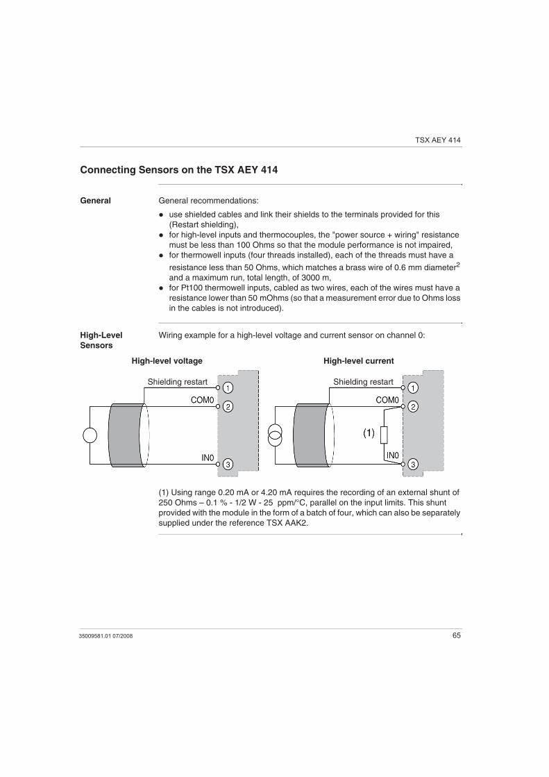
High-Level
Sensors
Wiring example for a high-level voltage and current sensor on channel 0:
(1) Using range 0.20 mA or 4.20 mA requires the recording of an external shunt of
250 Ohms – 0.1 % - 1/2 W - 25 ppm/°C, parallel on the input limits. This shunt
provided with the module in the form of a batch of four, which can also be separately
supplied under the reference TSX AAK2.
High-level voltage High-level current
Shielding restartShielding restart
TSX AEY 414
66 35009581.01 07/2008
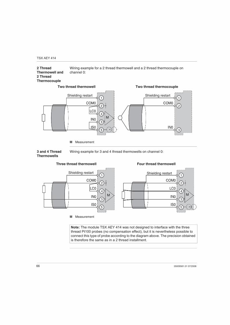
2 Thread
Thermowell and
2 Thread
Thermocouple
Wiring example for a 2 thread thermowell and a 2 thread thermocouple on
channel 0:
M Measurement
3 and 4 Thread
Thermowells
Wiring example for 3 and 4 thread thermowells on channel 0:
M Measurement
Two thread thermowell Two thread thermocouple
Shielding restartShielding restart
M
Four thread thermowellThree thread thermowell
Shielding restart Shielding restart
M M
Note: The module TSX AEY 414 was not designed to interface with the three
thread Pt100 probes (no compensation effect), but it is nevertheless possible to
connect this type of probe according to the diagram above. The precision obtained
is therefore the same as in a 2 thread installment.
TSX AEY 414
35009581.01 07/2008 67
Recommendations for installing the thermocouples for TSX AEY 414
At a Glance Described here you will find the recommendations for using a thermocouple with
internal and external cold junction compensation.
Use of internal
cold junction
compensation
When measurements are made by thermocouple with cold junction compensation
(and only in this case), it is advisable to follow the installation rules below :
the PLC must not be directly ventilated, as there must be natural convection,
variations in ambient temperature must be less than 5°C per hour,
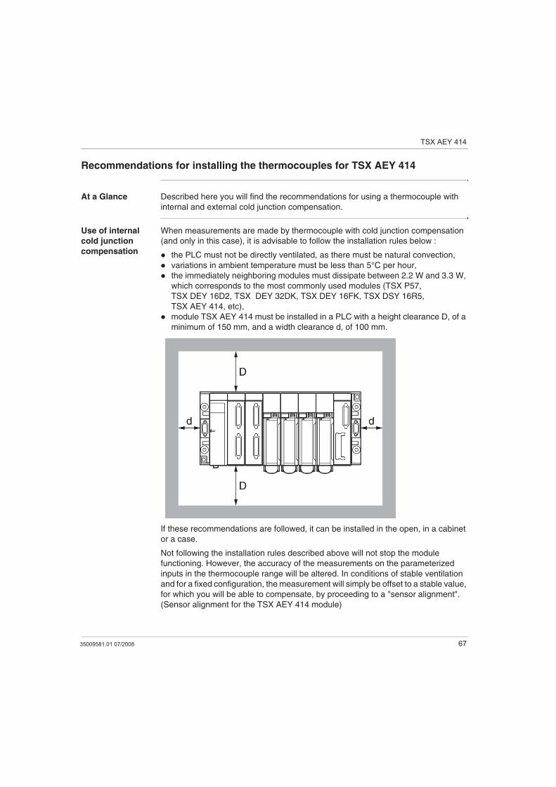
the immediately neighboring modules must dissipate between 2.2 W and 3.3 W,
which corresponds to the most commonly used modules (TSX P57,
TSX DEY 16D2, TSX DEY 32DK, TSX DEY 16FK, TSX DSY 16R5,
TSX AEY 414, etc),
module TSX AEY 414 must be installed in a PLC with a height clearance D, of a
minimum of 150 mm, and a width clearance d, of 100 mm.
If these recommendations are followed, it can be installed in the open, in a cabinet
or a case.
Not following the installation rules described above will not stop the module
functioning. However, the accuracy of the measurements on the parameterized
inputs in the thermocouple range will be altered. In conditions of stable ventilation
and for a fixed configuration, the measurement will simply be offset to a stable value,
for which you will be able to compensate, by proceeding to a "sensor alignment".
(Sensor alignment for the TSX AEY 414 module)
TSX AEY 414
68 35009581.01 07/2008
Use of external
cold junction
compensation
The use of a thermocouple with external cold junction compensation requires that
the temperature of the cold junction compensation is acquired with a Pt100 class A
probe on channel 0 (probe not provided). Channels 1, 2 and 3 of the module can
then be used for thermocouple measurement.
When used in this way, there are no particular installation constraints for module
TSX AEY 414. However, the Pt100 probe must be placed near the terminal block.
Note: Because the thermocouple B is not affected by the cold junction
compensation of 0 to 70°C, these installation constraints do not concern it.