Embed Size (px)
Citation preview
AN885Brushless DC (BLDC) Motor Fundamentals
INTRODUCTION
Brushless Direct Current (BLDC) motors are one of themotor types rapidly gaining popularity. BLDC motorsare used in industries such as Appliances, Automotive,Aerospace, Consumer, Medical, Industrial AutomationEquipment and Instrumentation.
As the name implies, BLDC motors do not use brushesfor commutation; instead, they are electronically com-mutated. BLDC motors have many advantages overbrushed DC motors and induction motors. A few ofthese are:
• Better speed versus torque characteristics• High dynamic response• High efficiency
• Long operating life• Noiseless operation• Higher speed ranges
In addition, the ratio of torque delivered to the size ofthe motor is higher, making it useful in applicationswhere space and weight are critical factors.
In this application note, we will discuss in detail the con-struction, working principle, characteristics and typicalapplications of BLDC motors. Refer to Appendix B:“Glossary” for a glossary of terms commonly usedwhen describing BLDC motors.
CONSTRUCTION AND OPERATING PRINCIPLE
BLDC motors are a type of synchronous motor. Thismeans the magnetic field generated by the stator andthe magnetic field generated by the rotor rotate at thesame frequency. BLDC motors do not experience the“slip” that is normally seen in induction motors.
BLDC motors come in single-phase, 2-phase and3-phase configurations. Corresponding to its type, thestator has the same number of windings. Out of these,3-phase motors are the most popular and widely used.This application note focuses on 3-phase motors.
Stator
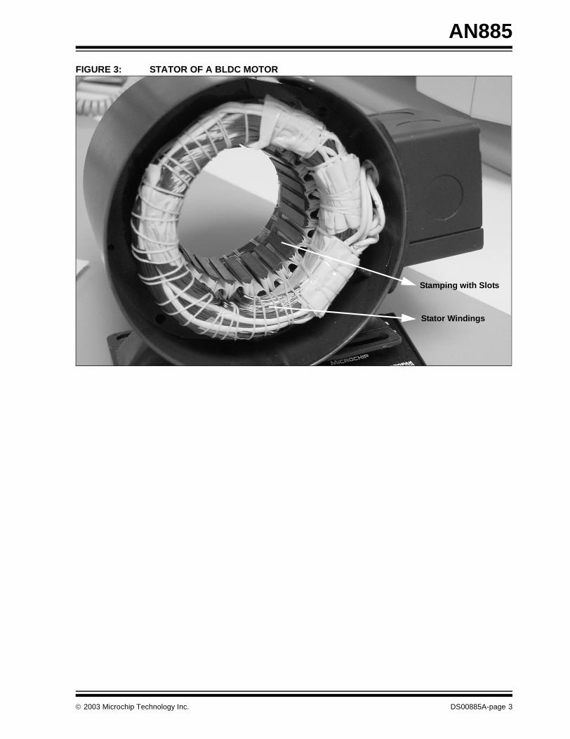
The stator of a BLDC motor consists of stacked steellaminations with windings placed in the slots that areaxially cut along the inner periphery (as shown inFigure 3). Traditionally, the stator resembles that of aninduction motor; however, the windings are distributedin a different manner. Most BLDC motors have threestator windings connected in star fashion. Each ofthese windings are constructed with numerous coilsinterconnected to form a winding. One or more coils areplaced in the slots and they are interconnected to makea winding. Each of these windings are distributed overthe stator periphery to form an even numbers of poles.
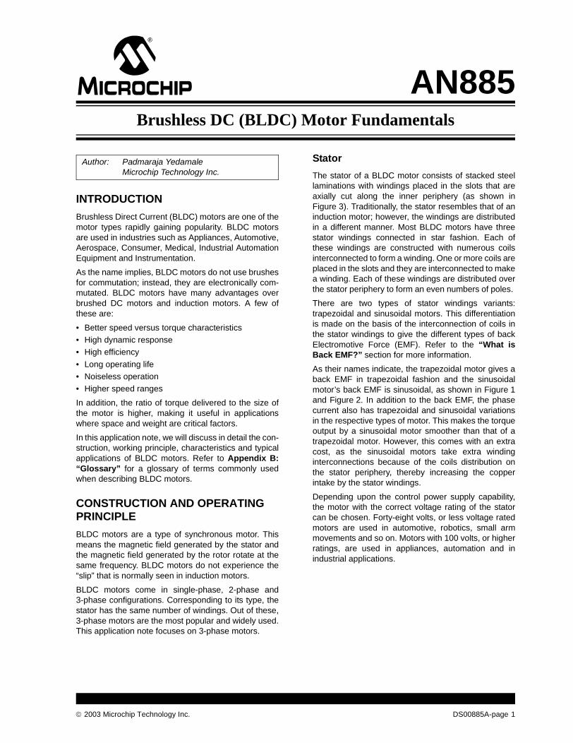
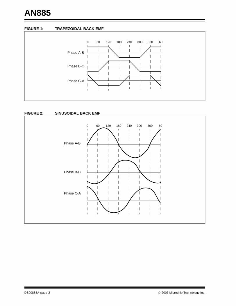
There are two types of stator windings variants:trapezoidal and sinusoidal motors. This differentiationis made on the basis of the interconnection of coils inthe stator windings to give the different types of backElectromotive Force (EMF). Refer to the “What isBack EMF?” section for more information.
As their names indicate, the trapezoidal motor gives aback EMF in trapezoidal fashion and the sinusoidalmotor’s back EMF is sinusoidal, as shown in Figure 1and Figure 2. In addition to the back EMF, the phasecurrent also has trapezoidal and sinusoidal variationsin the respective types of motor. This makes the torqueoutput by a sinusoidal motor smoother than that of atrapezoidal motor. However, this comes with an extracost, as the sinusoidal motors take extra windinginterconnections because of the coils distribution onthe stator periphery, thereby increasing the copperintake by the stator windings.
Depending upon the control power supply capability,the motor with the correct voltage rating of the statorcan be chosen. Forty-eight volts, or less voltage ratedmotors are used in automotive, robotics, small armmovements and so on. Motors with 100 volts, or higherratings, are used in appliances, automation and inindustrial applications.
Author: Padmaraja YedamaleMicrochip Technology Inc.
2003 Microchip Technology Inc. DS00885A-page 1
AN885
FIGURE 1: TRAPEZOIDAL BACK EMF
FIGURE 2: SINUSOIDAL BACK EMF
Phase A-B
Phase B-C
Phase C-A
0 60 120 180 240 300 360 60
Phase A-B
Phase B-C
Phase C-A
0 60 120 180 240 300 360 60
DS00885A-page 2 2003 Microchip Technology Inc.
AN885
FIGURE 3: STATOR OF A BLDC MOTOR
Stamping with Slots
Stator Windings
2003 Microchip Technology Inc. DS00885A-page 3
AN885
Rotor
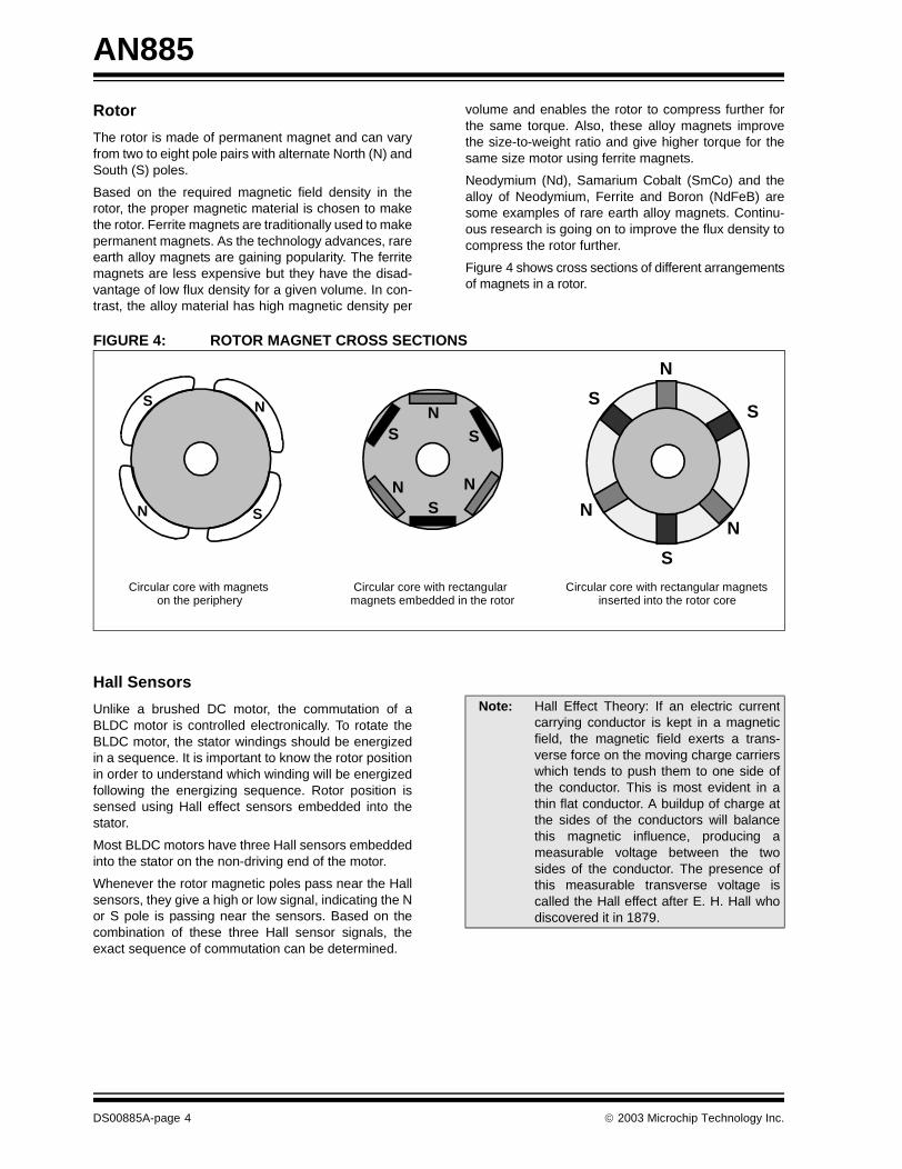
The rotor is made of permanent magnet and can varyfrom two to eight pole pairs with alternate North (N) andSouth (S) poles.
Based on the required magnetic field density in therotor, the proper magnetic material is chosen to makethe rotor. Ferrite magnets are traditionally used to makepermanent magnets. As the technology advances, rareearth alloy magnets are gaining popularity. The ferritemagnets are less expensive but they have the disad-vantage of low flux density for a given volume. In con-trast, the alloy material has high magnetic density per
volume and enables the rotor to compress further forthe same torque. Also, these alloy magnets improvethe size-to-weight ratio and give higher torque for thesame size motor using ferrite magnets.
Neodymium (Nd), Samarium Cobalt (SmCo) and thealloy of Neodymium, Ferrite and Boron (NdFeB) aresome examples of rare earth alloy magnets. Continu-ous research is going on to improve the flux density tocompress the rotor further.
Figure 4 shows cross sections of different arrangementsof magnets in a rotor.
FIGURE 4: ROTOR MAGNET CROSS SECTIONS
Hall Sensors
Unlike a brushed DC motor, the commutation of aBLDC motor is controlled electronically. To rotate theBLDC motor, the stator windings should be energizedin a sequence. It is important to know the rotor positionin order to understand which winding will be energizedfollowing the energizing sequence. Rotor position issensed using Hall effect sensors embedded into thestator.
Most BLDC motors have three Hall sensors embeddedinto the stator on the non-driving end of the motor.
Whenever the rotor magnetic poles pass near the Hallsensors, they give a high or low signal, indicating the Nor S pole is passing near the sensors. Based on thecombination of these three Hall sensor signals, theexact sequence of commutation can be determined.
N
N S
SN
S
NNS
S
N
N
S
S
N
S
Circular core with magnets on the periphery
Circular core with rectangular magnets embedded in the rotor
Circular core with rectangular magnets inserted into the rotor core
Note: Hall Effect Theory: If an electric currentcarrying conductor is kept in a magneticfield, the magnetic field exerts a trans-verse force on the moving charge carrierswhich tends to push them to one side ofthe conductor. This is most evident in athin flat conductor. A buildup of charge atthe sides of the conductors will balancethis magnetic influence, producing ameasurable voltage between the twosides of the conductor. The presence ofthis measurable transverse voltage iscalled the Hall effect after E. H. Hall whodiscovered it in 1879.
DS00885A-page 4 2003 Microchip Technology Inc.
AN885
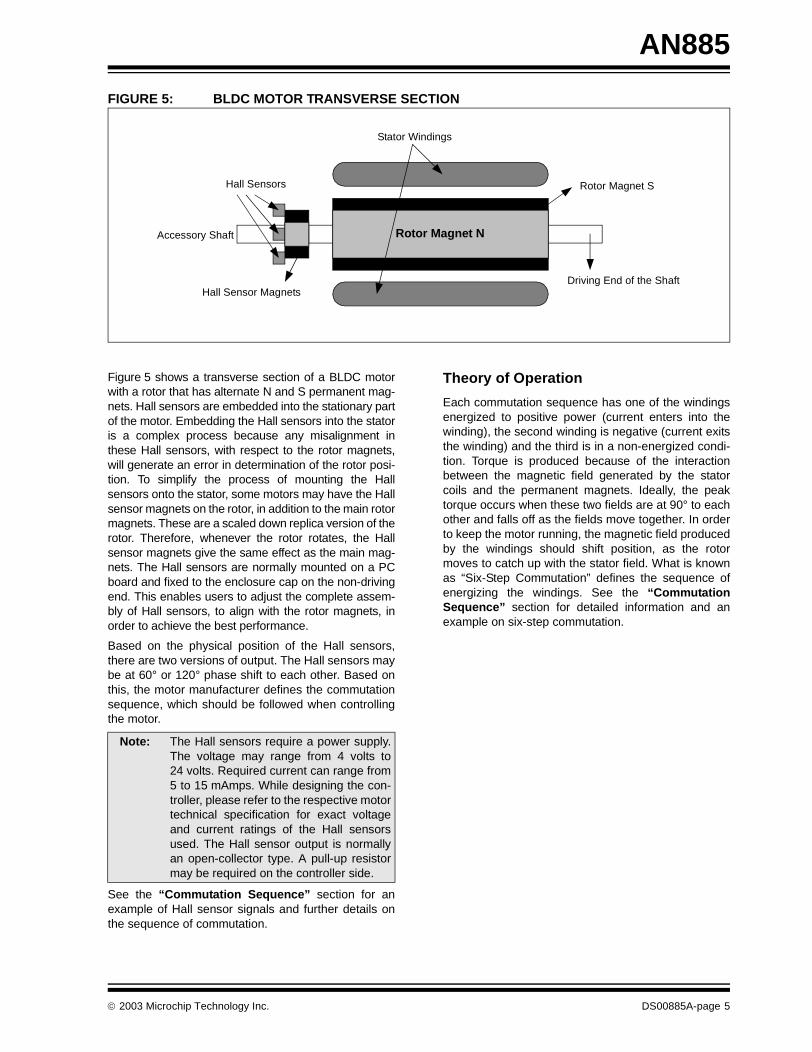
FIGURE 5: BLDC MOTOR TRANSVERSE SECTION
Figure 5 shows a transverse section of a BLDC motorwith a rotor that has alternate N and S permanent mag-nets. Hall sensors are embedded into the stationary partof the motor. Embedding the Hall sensors into the statoris a complex process because any misalignment inthese Hall sensors, with respect to the rotor magnets,will generate an error in determination of the rotor posi-tion. To simplify the process of mounting the Hallsensors onto the stator, some motors may have the Hallsensor magnets on the rotor, in addition to the main rotormagnets. These are a scaled down replica version of therotor. Therefore, whenever the rotor rotates, the Hallsensor magnets give the same effect as the main mag-nets. The Hall sensors are normally mounted on a PCboard and fixed to the enclosure cap on the non-drivingend. This enables users to adjust the complete assem-bly of Hall sensors, to align with the rotor magnets, inorder to achieve the best performance.
Based on the physical position of the Hall sensors,there are two versions of output. The Hall sensors maybe at 60° or 120° phase shift to each other. Based onthis, the motor manufacturer defines the commutationsequence, which should be followed when controllingthe motor.
See the “Commutation Sequence” section for anexample of Hall sensor signals and further details onthe sequence of commutation.
Theory of Operation
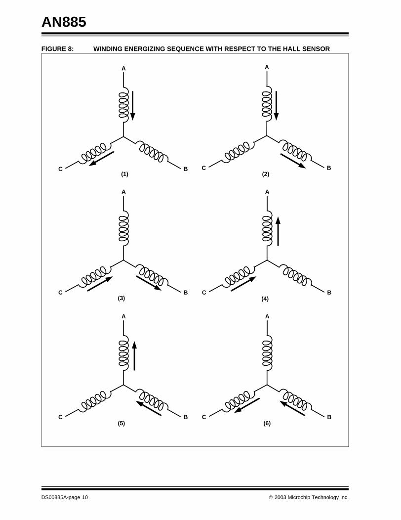
Each commutation sequence has one of the windingsenergized to positive power (current enters into thewinding), the second winding is negative (current exitsthe winding) and the third is in a non-energized condi-tion. Torque is produced because of the interactionbetween the magnetic field generated by the statorcoils and the permanent magnets. Ideally, the peaktorque occurs when these two fields are at 90° to eachother and falls off as the fields move together. In orderto keep the motor running, the magnetic field producedby the windings should shift position, as the rotormoves to catch up with the stator field. What is knownas “Six-Step Commutation” defines the sequence ofenergizing the windings. See the “CommutationSequence” section for detailed information and anexample on six-step commutation.
Rotor Magnet N
Rotor Magnet S
Stator Windings
Hall Sensors
Hall Sensor MagnetsDriving End of the Shaft
Accessory Shaft
Note: The Hall sensors require a power supply.The voltage may range from 4 volts to24 volts. Required current can range from5 to 15 mAmps. While designing the con-troller, please refer to the respective motortechnical specification for exact voltageand current ratings of the Hall sensorsused. The Hall sensor output is normallyan open-collector type. A pull-up resistormay be required on the controller side.
2003 Microchip Technology Inc. DS00885A-page 5
AN885
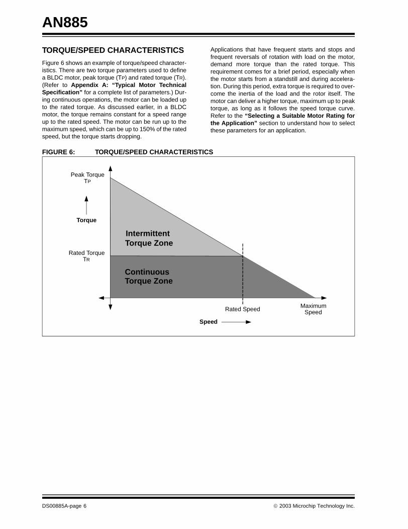
TORQUE/SPEED CHARACTERISTICS
Figure 6 shows an example of torque/speed character-istics. There are two torque parameters used to definea BLDC motor, peak torque (TP) and rated torque (TR).(Refer to Appendix A: “Typical Motor TechnicalSpecification” for a complete list of parameters.) Dur-ing continuous operations, the motor can be loaded upto the rated torque. As discussed earlier, in a BLDCmotor, the torque remains constant for a speed rangeup to the rated speed. The motor can be run up to themaximum speed, which can be up to 150% of the ratedspeed, but the torque starts dropping.
Applications that have frequent starts and stops andfrequent reversals of rotation with load on the motor,demand more torque than the rated torque. Thisrequirement comes for a brief period, especially whenthe motor starts from a standstill and during accelera-tion. During this period, extra torque is required to over-come the inertia of the load and the rotor itself. Themotor can deliver a higher torque, maximum up to peaktorque, as long as it follows the speed torque curve.Refer to the “Selecting a Suitable Motor Rating forthe Application” section to understand how to selectthese parameters for an application.
FIGURE 6: TORQUE/SPEED CHARACTERISTICS
Rated TorqueTR
Peak TorqueTP
Continuous
IntermittentTorque Zone
Torque
Speed
Rated Speed MaximumSpeed
Torque Zone
DS00885A-page 6 2003 Microchip Technology Inc.
AN885
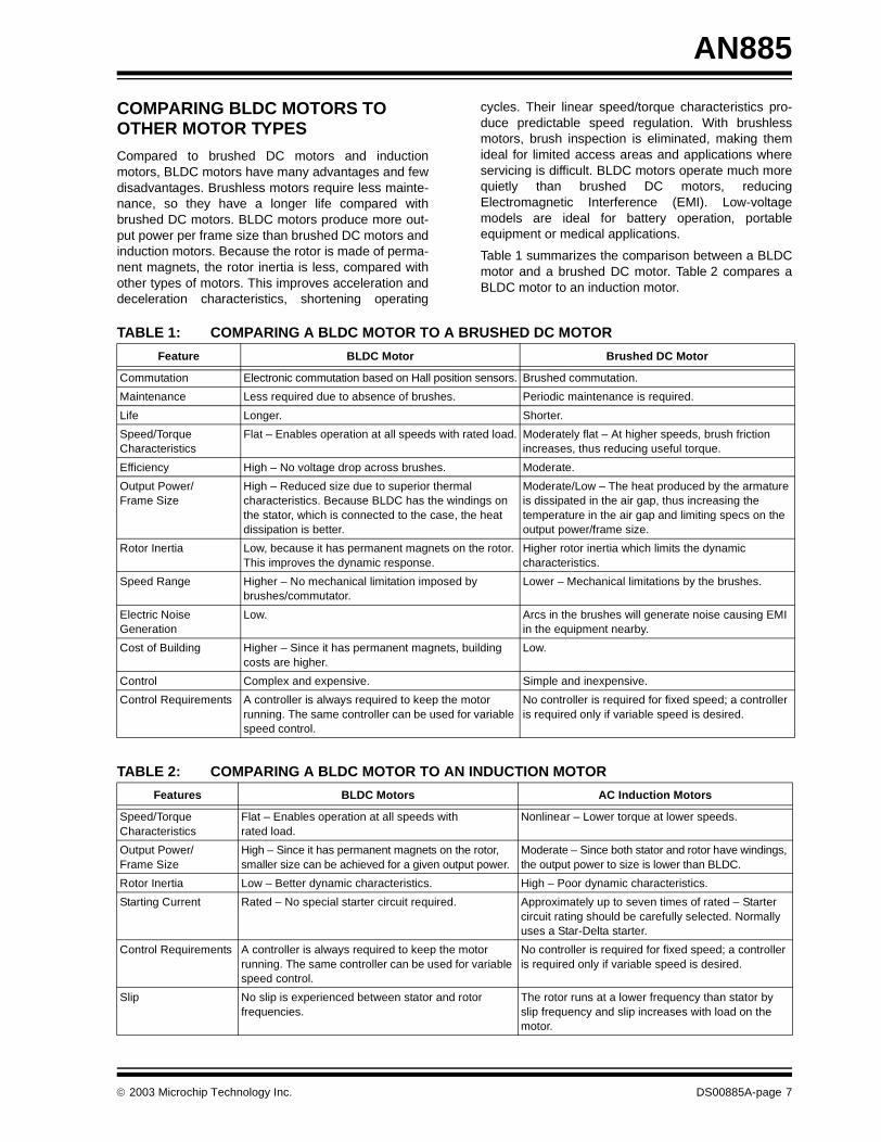
COMPARING BLDC MOTORS TO OTHER MOTOR TYPES
Compared to brushed DC motors and inductionmotors, BLDC motors have many advantages and fewdisadvantages. Brushless motors require less mainte-nance, so they have a longer life compared withbrushed DC motors. BLDC motors produce more out-put power per frame size than brushed DC motors andinduction motors. Because the rotor is made of perma-nent magnets, the rotor inertia is less, compared withother types of motors. This improves acceleration anddeceleration characteristics, shortening operating
cycles. Their linear speed/torque characteristics pro-duce predictable speed regulation. With brushlessmotors, brush inspection is eliminated, making themideal for limited access areas and applications whereservicing is difficult. BLDC motors operate much morequietly than brushed DC motors, reducingElectromagnetic Interference (EMI). Low-voltagemodels are ideal for battery operation, portableequipment or medical applications.
Table 1 summarizes the comparison between a BLDCmotor and a brushed DC motor. Table 2 compares aBLDC motor to an induction motor.
TABLE 1: COMPARING A BLDC MOTOR TO A BRUSHED DC MOTOR
TABLE 2: COMPARING A BLDC MOTOR TO AN INDUCTION MOTOR
Feature BLDC Motor Brushed DC Motor
Commutation Electronic commutation based on Hall position sensors. Brushed commutation.
Maintenance Less required due to absence of brushes. Periodic maintenance is required.
Life Longer. Shorter.
Speed/Torque Characteristics
Flat – Enables operation at all speeds with rated load. Moderately flat – At higher speeds, brush friction increases, thus reducing useful torque.
Efficiency High – No voltage drop across brushes. Moderate.
Output Power/Frame Size
High – Reduced size due to superior thermal characteristics. Because BLDC has the windings on the stator, which is connected to the case, the heat dissipation is better.
Moderate/Low – The heat produced by the armature is dissipated in the air gap, thus increasing thetemperature in the air gap and limiting specs on the output power/frame size.
Rotor Inertia Low, because it has permanent magnets on the rotor. This improves the dynamic response.
Higher rotor inertia which limits the dynamic characteristics.
Speed Range Higher – No mechanical limitation imposed by brushes/commutator.
Lower – Mechanical limitations by the brushes.
Electric Noise Generation
Low. Arcs in the brushes will generate noise causing EMI in the equipment nearby.
Cost of Building Higher – Since it has permanent magnets, building costs are higher.
Low.
Control Complex and expensive. Simple and inexpensive.
Control Requirements A controller is always required to keep the motor running. The same controller can be used for variable speed control.
No controller is required for fixed speed; a controller is required only if variable speed is desired.
Features BLDC Motors AC Induction Motors
Speed/Torque Characteristics
Flat – Enables operation at all speeds with rated load.
Nonlinear – Lower torque at lower speeds.
Output Power/Frame Size
High – Since it has permanent magnets on the rotor, smaller size can be achieved for a given output power.
Moderate – Since both stator and rotor have windings, the output power to size is lower than BLDC.
Rotor Inertia Low – Better dynamic characteristics. High – Poor dynamic characteristics.
Starting Current Rated – No special starter circuit required. Approximately up to seven times of rated – Starter circuit rating should be carefully selected. Normally uses a Star-Delta starter.
Control Requirements A controller is always required to keep the motor running. The same controller can be used for variable speed control.
No controller is required for fixed speed; a controller is required only if variable speed is desired.
Slip No slip is experienced between stator and rotor frequencies.
The rotor runs at a lower frequency than stator by slip frequency and slip increases with load on the motor.
2003 Microchip Technology Inc. DS00885A-page 7
AN885
COMMUTATION SEQUENCE
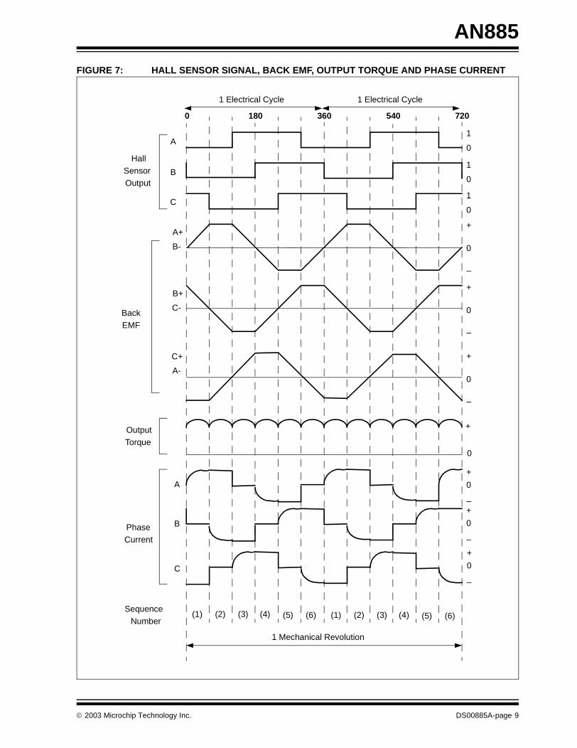
Figure 7 shows an example of Hall sensor signals withrespect to back EMF and the phase current. Figure 8shows the switching sequence that should be followedwith respect to the Hall sensors. The sequence numberson Figure 7 correspond to the numbers given in Figure 8.
Every 60 electrical degrees of rotation, one of the Hallsensors changes the state. Given this, it takes six stepsto complete an electrical cycle. In synchronous, withevery 60 electrical degrees, the phase current switch-ing should be updated. However, one electrical cyclemay not correspond to a complete mechanical revolu-tion of the rotor. The number of electrical cycles to berepeated to complete a mechanical rotation is deter-mined by the rotor pole pairs. For each rotor pole pairs,one electrical cycle is completed. So, the number ofelectrical cycles/rotations equals the rotor pole pairs.
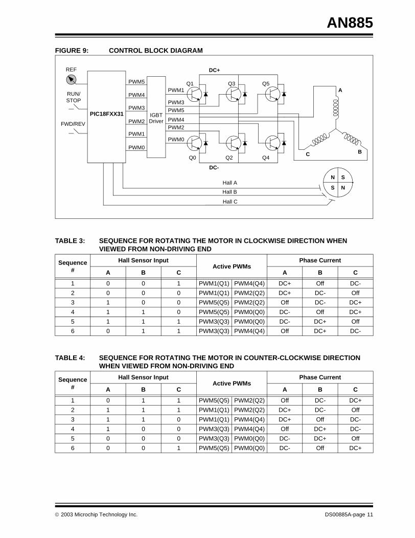
Figure 9 shows a block diagram of the controller usedto control a BLDC motor. Q0 to Q5 are the powerswitches controlled by the PIC18FXX31 micro-controller. Based on the motor voltage and currentratings, these switches can be MOSFETs, or IGBTs, orsimple bipolar transistors.
Table 3 and Table 4 show the sequence in which thesepower switches should be switched based on the Hallsensor inputs, A, B and C. Table 3 is for clockwise rota-tion of the motor and Table 4 is for counter clockwisemotor rotation. This is an example of Hall sensor sig-nals having a 60 degree phase shift with respect toeach other. As we have previously discussed in the“Hall Sensors” section, the Hall sensors may be at60° or 120° phase shift to each other. When deriving acontroller for a particular motor, the sequence definedby the motor manufacturer should be followed.
Referring to Figure 9, if the signals marked by PWMxare switched ON or OFF according to the sequence,the motor will run at the rated speed. This is assumingthat the DC bus voltage is equal to the motor rated volt-age, plus any losses across the switches. To vary thespeed, these signals should be Pulse Width Modulated(PWM) at a much higher frequency than the motor fre-quency. As a rule of thumb, the PWM frequency shouldbe at least 10 times that of the maximum frequency ofthe motor. When the duty cycle of PWM is varied withinthe sequences, the average voltage supplied to the sta-tor reduces, thus reducing the speed. Another advan-tage of having PWM is that, if the DC bus voltage ismuch higher than the motor rated voltage, the motorcan be controlled by limiting the percentage of PWMduty cycle corresponding to that of the motor rated volt-age. This adds flexibility to the controller to hook upmotors with different rated voltages and match theaverage voltage output by the controller, to the motorrated voltage, by controlling the PWM duty cycle.
There are different approaches of controls. If the PWMsignals are limited in the microcontroller, the upperswitches can be turned on for the entire time during thecorresponding sequence and the corresponding lowerswitch can be controlled by the required duty cycle onPWM.
The potentiometer, connected to the analog-to-digitalconverter channel in Figure 9, is for setting a speedreference. Based on this input voltage, the PWM dutycycle should be calculated.
Closed-Loop Control
The speed can be controlled in a closed loop bymeasuring the actual speed of the motor. The error inthe set speed and actual speed is calculated. A Propor-tional plus Integral plus Derivative (P.I.D.) controllercan be used to amplify the speed error and dynamicallyadjust the PWM duty cycle.
For low-cost, low-resolution speed requirements, theHall signals can be used to measure the speed feed-back. A timer from the PIC18FXX31 can be used tocount between two Hall transitions. With this count, theactual speed of the motor can be calculated.
For high-resolution speed measurements, an opticalencoder can be fitted onto the motor, which gives twosignals with 90 degrees phase difference. Using thesesignals, both speed and direction of rotation can bedetermined. Also, most of the encoders give a thirdindex signal, which is one pulse per revolution. Thiscan be used for positioning applications. Optical encod-ers are available with different choices of Pulse PerRevolution (PPR), ranging from hundreds tothousands.
DS00885A-page 8 2003 Microchip Technology Inc.
AN885
FIGURE 7: HALL SENSOR SIGNAL, BACK EMF, OUTPUT TORQUE AND PHASE CURRENT
(1) (2) (3) (4) (5) (6) (1) (2) (3) (4) (5) (6)
0 180 360 540 720
0
1
0
1
0
1
0
+
–
0
+
–
0
+
–
0
+
–
0
+
–
0
+
–
0
+
1 Mechanical Revolution
A
B
C
A+
B-
B+
C-
C+
A-
A
B
C
HallSensorOutput
BackEMF
OutputTorque
PhaseCurrent
SequenceNumber
1 Electrical Cycle 1 Electrical Cycle
2003 Microchip Technology Inc. DS00885A-page 9
AN885
FIGURE 8: WINDING ENERGIZING SEQUENCE WITH RESPECT TO THE HALL SENSOR
A
C B
A
C B
A
C B
A
C B
A
C B
A
C B
(1) (2)
(3) (4)
(5) (6)
DS00885A-page 10 2003 Microchip Technology Inc.
AN885
FIGURE 9: CONTROL BLOCK DIAGRAM
TABLE 3: SEQUENCE FOR ROTATING THE MOTOR IN CLOCKWISE DIRECTION WHEN VIEWED FROM NON-DRIVING END
TABLE 4: SEQUENCE FOR ROTATING THE MOTOR IN COUNTER-CLOCKWISE DIRECTION WHEN VIEWED FROM NON-DRIVING END
A
C B
PWM1
PWM3
PWM5
PWM0
PWM2PWM4
Q0
Q1
Q2
Q3
Q4
Q5
N S
S NHall A
Hall B
Hall C
DC+
DC-
RUN/STOP
FWD/REV
REF
PWM5
PWM4
PWM3
PWM2
PWM1
PWM0
IGBTDriver
PIC18FXX31
Sequence #
Hall Sensor InputActive PWMs
Phase Current
A B C A B C
1 0 0 1 PWM1(Q1) PWM4(Q4) DC+ Off DC-
2 0 0 0 PWM1(Q1) PWM2(Q2) DC+ DC- Off
3 1 0 0 PWM5(Q5) PWM2(Q2) Off DC- DC+
4 1 1 0 PWM5(Q5) PWM0(Q0) DC- Off DC+
5 1 1 1 PWM3(Q3) PWM0(Q0) DC- DC+ Off
6 0 1 1 PWM3(Q3) PWM4(Q4) Off DC+ DC-
Sequence #
Hall Sensor InputActive PWMs
Phase Current
A B C A B C
1 0 1 1 PWM5(Q5) PWM2(Q2) Off DC- DC+
2 1 1 1 PWM1(Q1) PWM2(Q2) DC+ DC- Off
3 1 1 0 PWM1(Q1) PWM4(Q4) DC+ Off DC-
4 1 0 0 PWM3(Q3) PWM4(Q4) Off DC+ DC-
5 0 0 0 PWM3(Q3) PWM0(Q0) DC- DC+ Off
6 0 0 1 PWM5(Q5) PWM0(Q0) DC- Off DC+
2003 Microchip Technology Inc. DS00885A-page 11
AN885
WHAT IS BACK EMF?
When a BLDC motor rotates, each winding generatesa voltage known as back Electromotive Force or backEMF, which opposes the main voltage supplied to thewindings according to Lenz’s Law. The polarity of thisback EMF is in opposite direction of the energizedvoltage. Back EMF depends mainly on three factors:
• Angular velocity of the rotor• Magnetic field generated by rotor magnets
• The number of turns in the stator windings
EQUATION 1:
Once the motor is designed, the rotor magnetic fieldand the number of turns in the stator windings remainconstant. The only factor that governs back EMF is theangular velocity or speed of the rotor and as the speedincreases, back EMF also increases. The motortechnical specification gives a parameter called, backEMF constant (refer to Appendix A: “Typical MotorTechnical Specification”), that can be used toestimate back EMF for a given speed.
The potential difference across a winding can becalculated by subtracting the back EMF value from thesupply voltage. The motors are designed with a backEMF constant in such a way that when the motor is run-ning at the rated speed, the potential differencebetween the back EMF and the supply voltage will besufficient for the motor to draw the rated current anddeliver the rated torque. If the motor is driven beyondthe rated speed, back EMF may increase substantially,thus decreasing the potential difference across thewinding, reducing the current drawn which results in adrooping torque curve. The last point on the speedcurve would be when the supply voltage is equal to thesum of the back EMF and the losses in the motor,where the current and torque are equal to zero.
Back EMF = (E) ∝ NlrBω
where:
N is the number of winding turns per phase,l is the length of the rotor, r is the internal radius of the rotor,B is the rotor magnetic field density andω is the motor’s angular velocity
DS00885A-page 12 2003 Microchip Technology Inc.
AN885
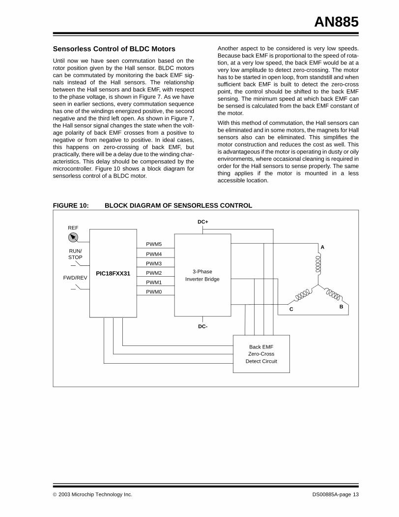
Sensorless Control of BLDC Motors
Until now we have seen commutation based on therotor position given by the Hall sensor. BLDC motorscan be commutated by monitoring the back EMF sig-nals instead of the Hall sensors. The relationshipbetween the Hall sensors and back EMF, with respectto the phase voltage, is shown in Figure 7. As we haveseen in earlier sections, every commutation sequencehas one of the windings energized positive, the secondnegative and the third left open. As shown in Figure 7,the Hall sensor signal changes the state when the volt-age polarity of back EMF crosses from a positive tonegative or from negative to positive. In ideal cases,this happens on zero-crossing of back EMF, butpractically, there will be a delay due to the winding char-acteristics. This delay should be compensated by themicrocontroller. Figure 10 shows a block diagram forsensorless control of a BLDC motor.
Another aspect to be considered is very low speeds.Because back EMF is proportional to the speed of rota-tion, at a very low speed, the back EMF would be at avery low amplitude to detect zero-crossing. The motorhas to be started in open loop, from standstill and whensufficient back EMF is built to detect the zero-crosspoint, the control should be shifted to the back EMFsensing. The minimum speed at which back EMF canbe sensed is calculated from the back EMF constant ofthe motor.
With this method of commutation, the Hall sensors canbe eliminated and in some motors, the magnets for Hallsensors also can be eliminated. This simplifies themotor construction and reduces the cost as well. Thisis advantageous if the motor is operating in dusty or oilyenvironments, where occasional cleaning is required inorder for the Hall sensors to sense properly. The samething applies if the motor is mounted in a lessaccessible location.
FIGURE 10: BLOCK DIAGRAM OF SENSORLESS CONTROL
PIC18FXX31
A
C B
PWM5
PWM4
PWM3
DC+
DC-
RUN/STOP
FWD/REV
REF
Back EMFZero-Cross
Detect Circuit
3-Phase
Inverter BridgePWM2
PWM1
PWM0
2003 Microchip Technology Inc. DS00885A-page 13
AN885
SELECTING A SUITABLE MOTOR RATING FOR THE APPLICATION
Selecting the right type of motor for the givenapplication is very important. Based on the load char-acteristics, the motor must be selected with the properrating. Three parameters govern the motor selection forthe given application. They are:
• Peak torque required for the application• RMS torque required
• The operating speed range
Peak Torque (TP) Requirement
The peak, or maximum torque required for the applica-tion, can be calculated by summing the load torque(TL), torque due to inertia (TJ) and the torque requiredto overcome the friction (TF).
There are other factors which will contribute to theoverall peak torque requirements. For example, thewindage loss which is contributed by the resistanceoffered by the air in the air gap. These factors are com-plicated to account for. Therefore, a 20% safety marginis given as a rule of thumb when calculating the torque.
EQUATION 2:
The torque due to inertia (TJ) is the torque required toaccelerate the load from standstill or from a lowerspeed to a higher speed. This can be calculated by tak-ing the product of load inertia, including the rotor inertiaand load acceleration.
EQUATION 3:
The mechanical system coupled to the motor shaftdetermines the load torque and the frictional torque.
RMS Torque Requirement (TRMS)
The Root Mean Square (RMS) torque can be roughlytranslated to the average continuous torque requiredfor the application. This depends upon many factors.The peak torque (TP), load torque (TL), torque due toinertia (TJ), frictional torque (TF) and acceleration,deceleration and run times.
The following equation gives the RMS torque requiredfor a typical application where TA is the accelerationtime, TR is the run time and TD is the deceleration time.
EQUATION 4:
Speed Range
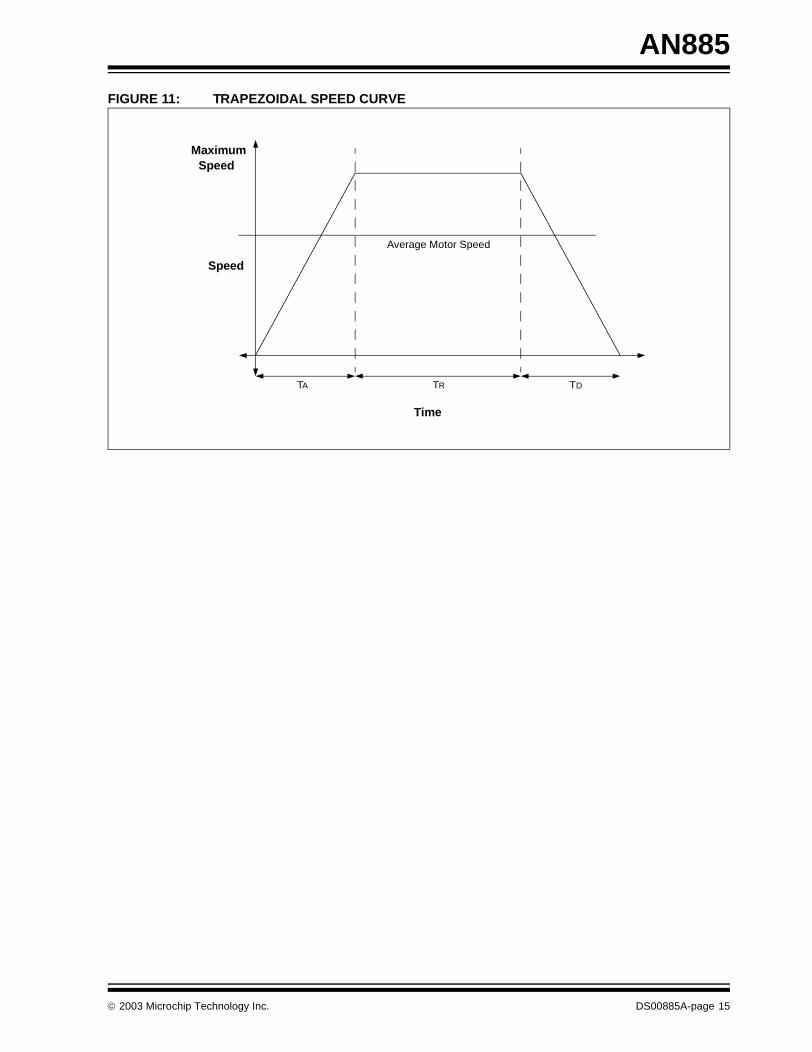
This is the motor speed required to drive the applicationand is determined by the type of application. For exam-ple, an application like a blower where the speed vari-ation is not very frequent and the maximum speed ofthe blower can be the average motor speed required.Whereas in the case of a point-to-point positioning sys-tem, like in a high-precision conveyer belt movement orrobotic arm movements, this would require a motor witha rated operating speed higher than the average move-ment speed. The higher operating speed can beaccounted for the components of the trapezoidal speedcurve, resulting in an average speed equal to themovement speed. The trapezoidal curve is shown inFigure 11.
It is always suggested to allow a safety margin of 10%,as a rule of thumb, to account for miscellaneous factorswhich are beyond our calculations.
∴ TP = (TL + TJ + TF) * 1.2
TJ = JL + M * αwhere:JL + M is the sum of the load and rotor inertia andα is the required acceleration
TRMS = √ [{TP2 TA + (TL + TF)2 TR +
(TJ – TL – TF)2 TD}/(TA + TR + TD)]
DS00885A-page 14 2003 Microchip Technology Inc.
AN885
FIGURE 11: TRAPEZOIDAL SPEED CURVE
TA TR TD
Time
Speed
Average Motor Speed
MaximumSpeed
2003 Microchip Technology Inc. DS00885A-page 15
AN885
TYPICAL BLDC MOTOR APPLICATIONS
BLDC motors find applications in every segment of themarket. Automotive, appliance, industrial controls,automation, aviation and so on, have applications forBLDC motors. Out of these, we can categorize the typeof BLDC motor control into three major types:
• Constant load• Varying loads
• Positioning applications
Applications With Constant Loads
These are the types of applications where a variablespeed is more important than keeping the accuracy ofthe speed at a set speed. In addition, the accelerationand deceleration rates are not dynamically changing. Inthese types of applications, the load is directly coupledto the motor shaft. For example, fans, pumps andblowers come under these types of applications. Theseapplications demand low-cost controllers, mostlyoperating in open-loop.
Applications With Varying Loads
These are the types of applications where the load onthe motor varies over a speed range. These applica-tions may demand a high-speed control accuracy andgood dynamic responses. In home appliances, wash-ers, dryers and compressors are good examples. Inautomotive, fuel pump control, electronic steering con-trol, engine control and electric vehicle control are goodexamples of these. In aerospace, there are a numberof applications, like centrifuges, pumps, robotic armcontrols, gyroscope controls and so on. Theseapplications may use speed feedback devices and mayrun in semi-closed loop or in total closed loop. Theseapplications use advanced control algorithms, thuscomplicating the controller. Also, this increases theprice of the complete system.
Positioning Applications
Most of the industrial and automation types of applica-tion come under this category. The applications in thiscategory have some kind of power transmission, whichcould be mechanical gears or timer belts, or a simplebelt driven system. In these applications, the dynamicresponse of speed and torque are important. Also,these applications may have frequent reversal of rota-tion direction. A typical cycle will have an acceleratingphase, a constant speed phase and a deceleration andpositioning phase, as shown in Figure 11. The load onthe motor may vary during all of these phases, causingthe controller to be complex. These systems mostlyoperate in closed loop. There could be three controlloops functioning simultaneously: Torque Control Loop,Speed Control Loop and Position Control Loop. Opticalencoder or synchronous resolvers are used formeasuring the actual speed of the motor. In somecases, the same sensors are used to get relative posi-tion information. Otherwise, separate position sensorsmay be used to get absolute positions. ComputerNumeric Controlled (CNC) machines are a goodexample of this. Process controls, machinery controlsand conveyer controls have plenty of applications inthis category.
SUMMARY
In conclusion, BLDC motors have advantages overbrushed DC motors and induction motors. They havebetter speed versus torque characteristics, highdynamic response, high efficiency, long operating life,noiseless operation, higher speed ranges, rugged con-struction and so on. Also, torque delivered to the motorsize is higher, making it useful in applications wherespace and weight are critical factors. With these advan-tages, BLDC motors find wide spread applications inautomotive, appliance, aerospace, consumer, medical,instrumentation and automation industries.
DS00885A-page 16 2003 Microchip Technology Inc.
AN885
APPENDIX A: TYPICAL MOTOR TECHNICAL SPECIFICATION
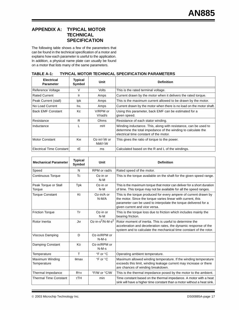
The following table shows a few of the parameters thatcan be found in the technical specification of a motor andexplains how each parameter is useful to the application.In addition, a physical name plate can usually be foundon a motor that lists many of the same parameters.
TABLE A-1: TYPICAL MOTOR TECHNICAL SPECIFICATION PARAMETERS
Electrical Parameter
Typical Symbol
Unit Definition
Reference Voltage V Volts This is the rated terminal voltage.
Rated Current Ir Amps Current drawn by the motor when it delivers the rated torque.
Peak Current (stall) Ipk Amps This is the maximum current allowed to be drawn by the motor.
No Load Current INL Amps Current drawn by the motor when there is no load on the motor shaft.
Back EMF Constant KE V/RPM orV/rad/s
Using this parameter, back EMF can be estimated for a given speed.
Resistance R Ohms Resistance of each stator winding.
Inductance L mH Winding inductance. This, along with resistance, can be used to determine the total impedance of the winding to calculate the electrical time constant of the motor.
Motor Constant KM Oz-in/√W orNM//√W
This gives the ratio of torque to the power.
Electrical Time Constant τE ms Calculated based on the R and L of the windings.
Mechanical ParameterTypical Symbol
Unit Definition
Speed N RPM or rad/s Rated speed of the motor.
Continuous Torque TC Oz-in orN-M
This is the torque available on the shaft for the given speed range.
Peak Torque or Stall Torque
Tpk Oz-in orN-M
This is the maximum torque that motor can deliver for a short duration of time. This torque may not be available for all the speed ranges.
Torque Constant Kt Oz-in/A orN-M/A
This is the torque produced for every ampere of current drawn by the motor. Since the torque varies linear with current, this parameter can be used to interpolate the torque delivered for a given current and vice versa.
Friction Torque TF Oz-in orN-M
This is the torque loss due to friction which includes mainly the bearing friction.
Rotor Inertia JM Oz-in-s2/N-M-s2 Rotor moment of inertia. This is useful to determine the acceleration and deceleration rates, the dynamic response of the system and to calculate the mechanical time constant of the rotor.
Viscous Damping D Oz-in/RPM orN-M-s
Damping Constant KD Oz-in/RPM or N-M-s
Temperature T °F or °C Operating ambient temperature.
Maximum Winding Temperature
θmax °F or °C Maximum allowed winding temperature. If the winding temperature exceeds this limit, winding leakage current may increase or there are chances of winding breakdown.
Thermal Impedance RTH °F/W or °C/W This is the thermal impedance posed by the motor to the ambient.
Thermal Time Constant τTH min Time constant based on the thermal impedance. A motor with a heat sink will have a higher time constant than a motor without a heat sink.
2003 Microchip Technology Inc. DS00885A-page 17
AN885
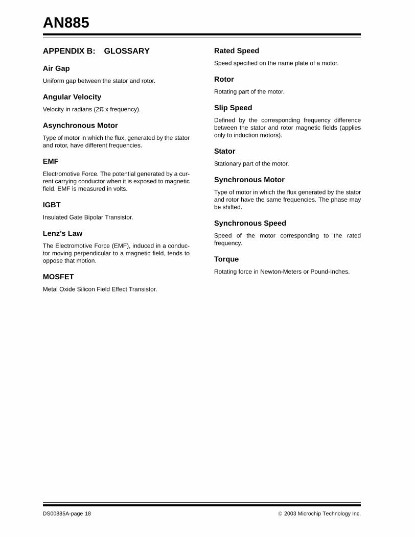
APPENDIX B: GLOSSARY
Air Gap
Uniform gap between the stator and rotor.
Angular Velocity
Velocity in radians (2π x frequency).
Asynchronous Motor
Type of motor in which the flux, generated by the statorand rotor, have different frequencies.
EMF
Electromotive Force. The potential generated by a cur-rent carrying conductor when it is exposed to magneticfield. EMF is measured in volts.
IGBT
Insulated Gate Bipolar Transistor.
Lenz’s Law
The Electromotive Force (EMF), induced in a conduc-tor moving perpendicular to a magnetic field, tends tooppose that motion.
MOSFET
Metal Oxide Silicon Field Effect Transistor.
Rated Speed
Speed specified on the name plate of a motor.
Rotor
Rotating part of the motor.
Slip Speed
Defined by the corresponding frequency differencebetween the stator and rotor magnetic fields (appliesonly to induction motors).
Stator
Stationary part of the motor.
Synchronous Motor
Type of motor in which the flux generated by the statorand rotor have the same frequencies. The phase maybe shifted.
Synchronous Speed
Speed of the motor corresponding to the ratedfrequency.
Torque
Rotating force in Newton-Meters or Pound-Inches.
DS00885A-page 18 2003 Microchip Technology Inc.
Note the following details of the code protection feature on Microchip devices:
• Microchip products meet the specification contained in their particular Microchip Data Sheet.
• Microchip believes that its family of products is one of the most secure families of its kind on the market today, when used in the intended manner and under normal conditions.
• There are dishonest and possibly illegal methods used to breach the code protection feature. All of these methods, to our knowledge, require using the Microchip products in a manner outside the operating specifications contained in Microchip's Data Sheets. Most likely, the person doing so is engaged in theft of intellectual property.
• Microchip is willing to work with the customer who is concerned about the integrity of their code.
• Neither Microchip nor any other semiconductor manufacturer can guarantee the security of their code. Code protection does not mean that we are guaranteeing the product as “unbreakable.”
Code protection is constantly evolving. We at Microchip are committed to continuously improving the code protection features of ourproducts. Attempts to break microchip’s code protection feature may be a violation of the Digital Millennium Copyright Act. If such actsallow unauthorized access to your software or other copyrighted work, you may have a right to sue for relief under that Act.
Information contained in this publication regarding deviceapplications and the like is intended through suggestion onlyand may be superseded by updates. It is your responsibility toensure that your application meets with your specifications.No representation or warranty is given and no liability isassumed by Microchip Technology Incorporated with respectto the accuracy or use of such information, or infringement ofpatents or other intellectual property rights arising from suchuse or otherwise. Use of Microchip’s products as critical com-ponents in life support systems is not authorized except withexpress written approval by Microchip. No licenses are con-veyed, implicitly or otherwise, under any intellectual propertyrights.
DS00885A-page 19
Trademarks
The Microchip name and logo, the Microchip logo, Accuron,dsPIC, KEELOQ, MPLAB, PIC, PICmicro, PICSTART, PRO MATE and PowerSmart are registered trademarks ofMicrochip Technology Incorporated in the U.S.A. and othercountries.
AmpLab, FilterLab, microID, MXDEV, MXLAB, PICMASTER,SEEVAL and The Embedded Control Solutions Company areregistered trademarks of Microchip Technology Incorporatedin the U.S.A.
Application Maestro, dsPICDEM, dsPICDEM.net, ECAN,ECONOMONITOR, FanSense, FlexROM, fuzzyLAB, In-Circuit Serial Programming, ICSP, ICEPIC, microPort,Migratable Memory, MPASM, MPLIB, MPLINK, MPSIM,PICkit, PICDEM, PICDEM.net, PowerCal, PowerInfo,PowerMate, PowerTool, rfLAB, rfPIC, Select Mode,SmartSensor, SmartShunt, SmartTel and Total Endurance aretrademarks of Microchip Technology Incorporated in theU.S.A. and other countries.
Serialized Quick Turn Programming (SQTP) is a service markof Microchip Technology Incorporated in the U.S.A.
All other trademarks mentioned herein are property of theirrespective companies.
© 2003, Microchip Technology Incorporated, Printed in theU.S.A., All Rights Reserved.
Printed on recycled paper.
2003 Microchip Technology Inc.
Microchip received QS-9000 quality system certification for its worldwide headquarters, design and wafer fabrication facilities in Chandler and Tempe, Arizona in July 1999 and Mountain View, California in March 2002. The Company’s quality system processes and procedures are QS-9000 compliant for its PICmicro® 8-bit MCUs, KEELOQ® code hopping devices, Serial EEPROMs, microperipherals, non-volatile memory and analog products. In addition, Microchip’s quality system for the design and manufacture of development systems is ISO 9001 certified.
DS00885A-page 20 2003 Microchip Technology Inc.
AMERICASCorporate Office2355 West Chandler Blvd.Chandler, AZ 85224-6199Tel: 480-792-7200 Fax: 480-792-7277Technical Support: 480-792-7627Web Address: http://www.microchip.com
Atlanta3780 Mansell Road, Suite 130Alpharetta, GA 30022Tel: 770-640-0034 Fax: 770-640-0307
Boston2 Lan Drive, Suite 120Westford, MA 01886Tel: 978-692-3848 Fax: 978-692-3821
Chicago333 Pierce Road, Suite 180Itasca, IL 60143Tel: 630-285-0071 Fax: 630-285-0075
Dallas4570 Westgrove Drive, Suite 160Addison, TX 75001Tel: 972-818-7423 Fax: 972-818-2924
DetroitTri-Atria Office Building 32255 Northwestern Highway, Suite 190Farmington Hills, MI 48334Tel: 248-538-2250Fax: 248-538-2260
Kokomo2767 S. Albright Road Kokomo, IN 46902Tel: 765-864-8360Fax: 765-864-8387
Los Angeles18201 Von Karman, Suite 1090Irvine, CA 92612Tel: 949-263-1888 Fax: 949-263-1338
Phoenix2355 West Chandler Blvd.Chandler, AZ 85224-6199Tel: 480-792-7966 Fax: 480-792-4338
San Jose2107 North First Street, Suite 590San Jose, CA 95131Tel: 408-436-7950 Fax: 408-436-7955
Toronto6285 Northam Drive, Suite 108Mississauga, Ontario L4V 1X5, CanadaTel: 905-673-0699 Fax: 905-673-6509
ASIA/PACIFICAustraliaSuite 22, 41 Rawson StreetEpping 2121, NSWAustraliaTel: 61-2-9868-6733 Fax: 61-2-9868-6755China - BeijingUnit 915Bei Hai Wan Tai Bldg.No. 6 Chaoyangmen Beidajie Beijing, 100027, No. ChinaTel: 86-10-85282100 Fax: 86-10-85282104China - ChengduRm. 2401-2402, 24th Floor, Ming Xing Financial TowerNo. 88 TIDU StreetChengdu 610016, ChinaTel: 86-28-86766200 Fax: 86-28-86766599China - FuzhouUnit 28F, World Trade PlazaNo. 71 Wusi RoadFuzhou 350001, ChinaTel: 86-591-7503506 Fax: 86-591-7503521China - Hong Kong SARUnit 901-6, Tower 2, Metroplaza223 Hing Fong RoadKwai Fong, N.T., Hong KongTel: 852-2401-1200 Fax: 852-2401-3431China - ShanghaiRoom 701, Bldg. BFar East International PlazaNo. 317 Xian Xia RoadShanghai, 200051Tel: 86-21-6275-5700 Fax: 86-21-6275-5060China - ShenzhenRm. 1812, 18/F, Building A, United PlazaNo. 5022 Binhe Road, Futian DistrictShenzhen 518033, ChinaTel: 86-755-82901380 Fax: 86-755-8295-1393China - ShundeRoom 401, Hongjian BuildingNo. 2 Fengxiangnan Road, Ronggui TownShunde City, Guangdong 528303, ChinaTel: 86-765-8395507 Fax: 86-765-8395571China - QingdaoRm. B505A, Fullhope Plaza,No. 12 Hong Kong Central Rd.Qingdao 266071, ChinaTel: 86-532-5027355 Fax: 86-532-5027205IndiaDivyasree Chambers1 Floor, Wing A (A3/A4)No. 11, O’Shaugnessey RoadBangalore, 560 025, IndiaTel: 91-80-2290061 Fax: 91-80-2290062JapanBenex S-1 6F3-18-20, ShinyokohamaKohoku-Ku, Yokohama-shiKanagawa, 222-0033, JapanTel: 81-45-471- 6166 Fax: 81-45-471-6122
Korea168-1, Youngbo Bldg. 3 FloorSamsung-Dong, Kangnam-KuSeoul, Korea 135-882Tel: 82-2-554-7200 Fax: 82-2-558-5932 or 82-2-558-5934Singapore200 Middle Road#07-02 Prime CentreSingapore, 188980Tel: 65-6334-8870 Fax: 65-6334-8850TaiwanKaohsiung Branch30F - 1 No. 8Min Chuan 2nd RoadKaohsiung 806, TaiwanTel: 886-7-536-4818Fax: 886-7-536-4803TaiwanTaiwan Branch11F-3, No. 207Tung Hua North RoadTaipei, 105, TaiwanTel: 886-2-2717-7175 Fax: 886-2-2545-0139
EUROPEAustriaDurisolstrasse 2A-4600 WelsAustriaTel: 43-7242-2244-399Fax: 43-7242-2244-393DenmarkRegus Business CentreLautrup hoj 1-3Ballerup DK-2750 DenmarkTel: 45-4420-9895 Fax: 45-4420-9910FranceParc d’Activite du Moulin de Massy43 Rue du Saule TrapuBatiment A - ler Etage91300 Massy, FranceTel: 33-1-69-53-63-20 Fax: 33-1-69-30-90-79GermanySteinheilstrasse 10D-85737 Ismaning, GermanyTel: 49-89-627-144-0 Fax: 49-89-627-144-44ItalyVia Quasimodo, 1220025 Legnano (MI)Milan, Italy Tel: 39-0331-742611 Fax: 39-0331-466781NetherlandsP. A. De Biesbosch 14NL-5152 SC Drunen, NetherlandsTel: 31-416-690399 Fax: 31-416-690340United Kingdom505 Eskdale RoadWinnersh TriangleWokingham Berkshire, England RG41 5TUTel: 44-118-921-5869Fax: 44-118-921-5820
07/28/03
WORLDWIDE SALES AND SERVICE


![EXPERIMENTAL CHARACTERIZATION OF BRUSHLESS DC … (06.29.16... · and brushless DC motors are well suited to this application [1]. Among these, the brushless DC (BLDC) motor stands](https://img.pdfslide.us/doc/110x75/5e8e60da94c7bd15f05a070f/experimental-characterization-of-brushless-dc-062916-and-brushless-dc-motors.jpg)