Embed Size (px)
DESCRIPTION
Heat management
Citation preview

TM
Freescale and the Freescale logo are trademarks of Freescale Semiconductor, Inc. ARM
is the registered trademark of ARM Limited. ARM Cortex™-A9 is a trademark of ARM
Limited. All other product or service names are the property of their respective owners.
© 2012 Freescale Semiconductor, Inc.
i.MX 6 Series
Thermal Management Guidelines
Document Number: AN4579
Rev. 0, 11/2012

2 TM
Freescale and the Freescale logo are trademarks of Freescale Semiconductor, Inc. ARM is the registered trademark of ARM Limited. ARM
Cortex™-A9 is a trademark of ARM Limited. All other product or service names are the property of their respective owners.
© 2012 Freescale Semiconductor, Inc.
Overview o General overview of the thermal issues when using high performance applications
o The relationship between power consumption , heat and activity profile (duty-cycle) for a system
Thermal Management Concepts o General thermal related terms, thermal resistance (and conductivity)
o Thermal management solutions: heat spreaders, thermal gap fillers
Thermal Attributes o i.MX 6Dual/6Quad thermal package specifications (defined by JEDEC).
o Building thermal models (using package details, board details)
o Thermal solutions and tradeoffs
Thermal Simulations o How to simulate heat at the system level: board, components, enclosure and tools
o Assumptions of models used in simulations and the summary of thermal simulation results
Software Thermal Management Techniques o Software thermal management techniques
o Software implemented features to manage power and provide thermal regulation
Recommendations /Conclusion o Final recommendations based on simulation results
Appendix /References o Additional References and Resources
o Heat spreading examples based on other vendors
i.MX 6 Series - Thermal Management Guidelines

TM 3
Freescale and the Freescale logo are trademarks of Freescale Semiconductor, Inc. ARM is the registered trademark of ARM Limited. ARM
Cortex™-A9 is a trademark of ARM Limited. All other product or service names are the property of their respective owners.
© 2012 Freescale Semiconductor, Inc.
Content
• Overview
• Thermal Management Concepts
• Thermal Attributes
• Thermal Simulations
• Software Thermal Management Techniques
• Recommendations /Conclusion
• Appendix/References

TM 4
Freescale and the Freescale logo are trademarks of Freescale Semiconductor, Inc. ARM is the registered trademark of ARM Limited. ARM
Cortex™-A9 is a trademark of ARM Limited. All other product or service names are the property of their respective owners.
© 2012 Freescale Semiconductor, Inc.
Overview : Thermal Management
he i.MX 6 series of multimedia-focused products offer high performance processing optimized for
the lowest power consumption. For such high performance devices , the power dissipation of the
device requires that customers consider the thermal performance of the device and design their
system accordingly.
Thermal management becomes critical when the power dissipation level increases in certain high
performance use cases. Under these use cases integrated thermal management from package to the
system level is needed to ensure the performance and reliability of the i.MX 6Dual/6Quad SoC and the
system:
Operating Environment : Thermal management becomes a challenge especially when
operating in a high ambient temperature environment. One way to constrain the environment
ambient operating temperature for the device is to ensure it must be at or lower than a given
temperature.
Expected Power Consumption: This depends on the modes of operation, and the use-cases
that the system will be running. Dynamic power is a nonlinear function of capacitance,
frequency, and volts squared (Pdynamic = CfV2). The nonlinear nature of this relationship
illustrates that as the switching frequency gets higher, the amount of power and heat grows
exponentially. Operating at the highest frequency to achieve the highest performance implies
paying a penalty in terms of power consumption (battery life), and dissipated power in the form
of heat. Different thermal solutions are required depending on the system power and utilization
Device Usage & Operational Duty Cycle : The operational duration at various environment
conditions needs to be considered. Understanding the target operation duty cycle is important when considering the end thermal solution for the system

TM 5
Freescale and the Freescale logo are trademarks of Freescale Semiconductor, Inc. ARM is the registered trademark of ARM Limited. ARM
Cortex™-A9 is a trademark of ARM Limited. All other product or service names are the property of their respective owners.
© 2012 Freescale Semiconductor, Inc.
Overview : Thermal Management
Consume Less Power - Generate Less heat
Heat in an embedded system is a by-product of power and the best way to generate less heat is to
consume less power. Once heat is generated, the job then becomes to transfer it effectively by
providing an efficient path from the device to the environment via thermal pads, epoxy or any method
that makes use of conduction, convection, or facilitates radiation.
The general strategy for thermal management focuses on:
Increasing the heat-dissipation capability of the thermal solutions
Expanding the thermal envelopes of systems
Minimizing impact of local hot spots by improving heat spreading
Developing thermal solutions that meet cost constraints
Solutions that fit within form factor considerations of the product chassis
Thermal Management Strategies
There are basically two types of thermal management strategies:
Active thermal management techniques available for embedded systems provide lower thermal
resistances and better heat dissipation, however are expensive and have large form factors
Passive thermal management techniques by enhancing conduction and natural convection
provide more cost effective solutions, up to certain power levels without introducing any
reliability concerns and are discussed primarily in this report for the i.MX 6Dual/6Quad SoC
i.MX 6
TM 6
Freescale and the Freescale logo are trademarks of Freescale Semiconductor, Inc. ARM is the registered trademark of ARM Limited. ARM
Cortex™-A9 is a trademark of ARM Limited. All other product or service names are the property of their respective owners.
© 2012 Freescale Semiconductor, Inc.
Overview : Thermal Management System Design
Thermal Design Strategy
A holistic thermal design strategy needs to consider all aspects of the thermal hierarchy. Historically, the
processor was the most energy hungry component of a typical embedded computing system. However,
processors such as the i.MX6 family have become more energy efficient and more effective at managing their
own power consumption (thanks to sophisticated power/clock management architectures and techniques).
In contrast, memory energy consumption has been growing, as multi-core CPUs with multiple hardware
accelerators are requiring increasing DDR memory bandwidth and capacity. The main system memory (DDR)
can consume significant system energy in active modes. Hence the main system memory power, equally
challenges both power management system and thermal design.
Thermal Contributors
Customers also need to consider the impact of other components on the system board due to their heat
generating capacity. Typical high power devices in a system include but are not limited to the following:
• Power Management IC’s or External LDO’s
• RF components such as PA, transmitters & Modems
• LCD, LED and OLED displays
• High Speed memories and Transceivers
Although many of the techniques discussed in this document apply to all heat generating components, we
primarily focus on the i.MX 6 series and i.MX 6Dual/6Quad SoC in particular. Memory power savings are
briefly discussed in the Software Thermal Management Techniques section of this document.

TM 7
Freescale and the Freescale logo are trademarks of Freescale Semiconductor, Inc. ARM is the registered trademark of ARM Limited. ARM
Cortex™-A9 is a trademark of ARM Limited. All other product or service names are the property of their respective owners.
© 2012 Freescale Semiconductor, Inc.
Overview : Thermal Dissipation
Thermal Design Power The Thermal Design Power (TDP), also referred to the thermal design point, is of primary
interest to the thermal solution designer and it represents the maximum sustained power
dissipated by the i.MX 6Dual/6Quad processor, across a set of realistic applications. Designing
for TDP is important to ensure reliable long-term performance.
Thermal Time Constant The steady state is predicted by the thermal resistances, but the time constant to get there is
significant. This time constant sets the length of time to average the consumption of the chip
over for bursty operations and will scale up and down with the board and packaging size/mass.
It is possible for there to be brief bursts of activity where the power dissipated is larger than the
target TDP, but no action is required as long as the bursts are within the thermal time constant
and do not violate the i.MX 6Dual/6Quad thermal specifications.
Some of the typical usage profiles are natively bursty - internet browsing (burst per user
activity), video/audio playback (periodical bursts associated with frame processing). For
instance, when we perform temperature sensor testing, we need to wait for the chip and board
to stabilize thermally once at the correct temperature. This is discussed further in the Software
Thermal Management Techniques section of this document.

TM 8
Freescale and the Freescale logo are trademarks of Freescale Semiconductor, Inc. ARM is the registered trademark of ARM Limited. ARM
Cortex™-A9 is a trademark of ARM Limited. All other product or service names are the property of their respective owners.
© 2012 Freescale Semiconductor, Inc.
Overview : Thermal Dissipation Activity Profile
The activity profile of the application can have a significant impact on the thermal
management techniques that need to be employed, and on the thermal design power.
The main types of activities can be classified as follows:
Short Bursts below thermal time constant
• Short bursts of intensive processing followed by long intervals of the IC/System being
idle can automatically regulate the heat without much external intervention.
Long Bursts above thermal time constant
• Long bursts of intensive processing followed by long intervals of the IC/System being
idle may require some external intervention such as software thermal management.
Continuous Operation at an average power
• However continuous high performance usage without any idling can cause the system
temperature to rise, hence making it necessary to have other forms of thermal
management.
The more intensive the use case with all major power contributors active such as the
ARM Cores and Graphics Processing Unit (GPU) the higher the potential thermal
energy that needs to be effectively dissipated.

TM 9
Freescale and the Freescale logo are trademarks of Freescale Semiconductor, Inc. ARM is the registered trademark of ARM Limited. ARM
Cortex™-A9 is a trademark of ARM Limited. All other product or service names are the property of their respective owners.
© 2012 Freescale Semiconductor, Inc.
Case Thermocouple
Power dissipation on top surface of
die
Die temperature: TJ
TA Ambient
Temperature PCB Temperature
Power dissipated in the die is conducted to the top surface of the package and to
the board and then dissipated to the environment. • Tj “Junction” or die temperature
• TA Ambient or air temperature near the device
• TB Board temperature at the edge of the device
• TC Case temperature
Overview : Thermal Dissipation
Orange arrows show the heat flow.
Primary Heat Path Thermal Simulations and testing have shown that the dominant heat transfer inside small form factor
devices is via conduction due to the confined space inside the enclosure, where the natural convection
effect is even negligible. Most of the heat generated by a high power component is dissipated through
the system board, when no thermal solution is implemented on the top of the package, which indicates
that the primary heat path is from junction to the board.
TC
TM 10
Freescale and the Freescale logo are trademarks of Freescale Semiconductor, Inc. ARM is the registered trademark of ARM Limited. ARM
Cortex™-A9 is a trademark of ARM Limited. All other product or service names are the property of their respective owners.
© 2012 Freescale Semiconductor, Inc.
Content
• Overview
• Thermal Management Concepts
• Thermal Attributes
• Thermal Simulations
• Software Thermal Management Techniques
• Recommendations /Conclusion
• Appendix/References

TM 11
Freescale and the Freescale logo are trademarks of Freescale Semiconductor, Inc. ARM is the registered trademark of ARM Limited. ARM
Cortex™-A9 is a trademark of ARM Limited. All other product or service names are the property of their respective owners.
© 2012 Freescale Semiconductor, Inc.
Passive Thermal Management This section investigates various passive thermal management strategies and primarily
focuses on handheld devices with small form factors. Spreading heat and cooling
components in handheld devices poses unique problems.
Because of the high density of components and small form factor, very little room is available
for a thermal solution. Given the limited airflow and the presence of significant amounts of
lower thermal conductivity material heat dissipation becomes a challenge. Most heat transfer
is by conduction and radiation.
Passive thermal management techniques that are typically used are listed below:
Thermal Gap Fillers/Thermal Interface Materials
Heat Spreaders
Copper
Graphite
Heat Shields
Thermal Management Techniques
Sealed Box,
Small vertical
spacing
TM 12
Freescale and the Freescale logo are trademarks of Freescale Semiconductor, Inc. ARM is the registered trademark of ARM Limited. ARM
Cortex™-A9 is a trademark of ARM Limited. All other product or service names are the property of their respective owners.
© 2012 Freescale Semiconductor, Inc.
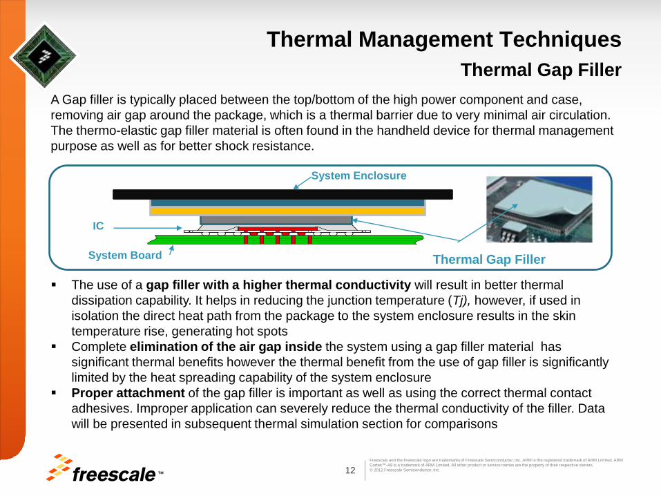
A Gap filler is typically placed between the top/bottom of the high power component and case,
removing air gap around the package, which is a thermal barrier due to very minimal air circulation.
The thermo-elastic gap filler material is often found in the handheld device for thermal management
purpose as well as for better shock resistance.
The use of a gap filler with a higher thermal conductivity will result in better thermal
dissipation capability. It helps in reducing the junction temperature (Tj), however, if used in
isolation the direct heat path from the package to the system enclosure results in the skin
temperature rise, generating hot spots
Complete elimination of the air gap inside the system using a gap filler material has
significant thermal benefits however the thermal benefit from the use of gap filler is significantly
limited by the heat spreading capability of the system enclosure
Proper attachment of the gap filler is important as well as using the correct thermal contact
adhesives. Improper application can severely reduce the thermal conductivity of the filler. Data
will be presented in subsequent thermal simulation section for comparisons
Thermal Management Techniques
Thermal Gap Filler
System Enclosure
System Board
IC
Thermal Gap Filler

TM 13
Freescale and the Freescale logo are trademarks of Freescale Semiconductor, Inc. ARM is the registered trademark of ARM Limited. ARM
Cortex™-A9 is a trademark of ARM Limited. All other product or service names are the property of their respective owners.
© 2012 Freescale Semiconductor, Inc.
The Need for Heat Spreaders Providing the conduction heat path between the package and the system
enclosure, alone, may not be sufficient enough for thermal management of high
power component for extended operations
The gap filler material can serve as temporary thermal storage, delaying the time
to reach steady state, however, is not sufficient to dissipate the thermal energy
For extended operation or for high power consuming use cases, enhancing the
heat spreading capability of the device enclosure becomes critical
Heat spreaders are used to spread the heat while transporting it from the die to
the PCB, product chassis or a heat sink (if the product design form factor permits),
which in turn dissipates heat to the local environment
To increase cooling capability, the strategy is to even out the temperature profiles
due to non uniform power distributions, as close to the source as possible, by
spreading out the heat. Heat spreaders serve three primary purposes:
Touch Temperature Reduction
High power/hot component temperature reduction/cooling
Shielding heat
The next part of this document discusses the advantages of heat spreaders along
with some of the design considerations for heat spreader material selection and
placement in the final product
Thermal Management Techniques
Heat Spreaders

TM 14
Freescale and the Freescale logo are trademarks of Freescale Semiconductor, Inc. ARM is the registered trademark of ARM Limited. ARM
Cortex™-A9 is a trademark of ARM Limited. All other product or service names are the property of their respective owners.
© 2012 Freescale Semiconductor, Inc.
Thermal Management Techniques
Heat Spreaders
A thermally conductive heat spreader can be placed on the high power components
and this heat spreader can enable spreading and evening out of the hot spots and
could be designed to make direct contact with the system enclosure as shown below:
This design concept significantly increased the power dissipation capability, by
reducing overall system thermal resistance.
The type of heat spreader to be used is dependent on the customers’ application
available enclosure space and budget considerations
System Enclosure
Thermal Interface
Material
Heat
Spreader
System Board
IC
Thermal
Gap Filler

TM 15
Freescale and the Freescale logo are trademarks of Freescale Semiconductor, Inc. ARM is the registered trademark of ARM Limited. ARM
Cortex™-A9 is a trademark of ARM Limited. All other product or service names are the property of their respective owners.
© 2012 Freescale Semiconductor, Inc.
Copper Advantages Copper has been used extensively in many thermal applications including heat spreaders
The excellent thermal conductivity of copper(400W/mK) in all directions (x,y & z) makes it
an effective heat spreader
Simulations with the Copper heat spreader always showed better heat dissipation
capability when comparing a model without the heat spreader, again due to better heat
dissipation capability
Simulations and testing performed clearly show the benefits of using a heat spreader.
Please refer to the Thermal Simulations section of this document for further information
Copper Limitations Although copper does have good thermal conductivity the increasing cost of copper has
made it more inhibitive for mass deployment. Hence the area of the copper could be
limited to the area on the enclosure to reduce cost or by using cheaper copper tape
The thermal conductivity of copper(400W/K) in all directions can be problematic since a
hot spot could just translate vertically to a different location, possibly closer to the
enclosure hence creating a hot spot on the case. Copper hence is not best suited for
touch temperature reduction applications.
Thermal Management Techniques Copper Heat Spreaders
Hot Spot on a high power component
can easily appear as a similar hot spot
on a copper spreader if not sized correctly

TM 16
Freescale and the Freescale logo are trademarks of Freescale Semiconductor, Inc. ARM is the registered trademark of ARM Limited. ARM
Cortex™-A9 is a trademark of ARM Limited. All other product or service names are the property of their respective owners.
© 2012 Freescale Semiconductor, Inc.
Graphite matches the thermal performance of copper in two directions(x,y), at a lower
weight and cost.
Due to its relatively low cost, the area that the graphite heat spreader covers ,could be
potentially large, covering all heat generating components
Flexible graphite heat spreaders give product designers the tools to overcome the
complex challenges associated with thermal management
Some of the key product applications are listed below
Cooling of sensitive components
Elimination of fans & active cooling
Touch temperature reduction
Thermal shielding of Li-Ion batteries
Cooling of LED and power components
Mitigation of AMOLED and LCD display hot spots Improves brightness uniformity
Decreases image sticking and burn-in
Minimizes warping of back light unit and films
Reduces chassis distortion
Reduces the severity of stress-induced birefringence
Applications of Graphite heat spreaders in actual products are shown in Appendix E
Thermal Management Techniques Graphite Heat Spreaders

TM 17
Freescale and the Freescale logo are trademarks of Freescale Semiconductor, Inc. ARM is the registered trademark of ARM Limited. ARM
Cortex™-A9 is a trademark of ARM Limited. All other product or service names are the property of their respective owners.
© 2012 Freescale Semiconductor, Inc.
Natural graphite matches the thermal performance of copper in two directions at 15-22% of the
weight. The material is suited in a variety of heat spreading applications where in-plane thermal
conductivity dominates.
Advances in graphite based spreader products have lead to pyrolitic graphite sheets comprising
of highly oriented polymers with thermal conductivity reaching 1750 W/mK (~ 4 times more than
copper). The cost of these products does however increase with the higher thermal conductivity
and can be prohibitive for applications requiring a large surface are to be covered
Lamination, molding and embossing methods can be employed to produce a variety of different
component forms. Also, because of their flexibility, natural graphite materials are able to conform
well to surfaces under low contact pressures. This combination of properties makes natural
graphite a potential substitute for aluminum and copper materials as heat spreaders
The other potentially attractive feature of natural graphite is that its high specific surface area
results in very high electromagnetic interference shielding over the frequency range of 1-2 GHz.
Thermal Management Techniques Graphite Heat Spreaders
The highly anisotropic thermal conductivity of natural graphite
implies that a graphite sheet can function as both a heat spreader
and an insulator. It can be used to eliminate localized hot spots in
electronic components resulting from uneven loading, surface
distortion and uneven heat distribution on the die surface.

TM 18
Freescale and the Freescale logo are trademarks of Freescale Semiconductor, Inc. ARM is the registered trademark of ARM Limited. ARM
Cortex™-A9 is a trademark of ARM Limited. All other product or service names are the property of their respective owners.
© 2012 Freescale Semiconductor, Inc.
Recommended to use graphite to increase the effective surface area of the heat source and to
move heat from a heat source to a heat sink. The customer design will be more thermally
effective if the heat sink is able to shed heat to the environment.
Mechanical Considerations
Graphite should not be used as a structural material. It will not stand up to lateral, shearing,
or torque forces. Graphite has negligible thickness reduction due to compression
Flexible graphite must be mechanically secured to a structure -- either within a structure
(i.e. between rigid layers) or via a fastener such as adhesive or thermal gap pad
The spreader could be designed to lie on top of the components and held in place by
the contact pressure generated by the case maximizing the thermal attach area
The application must be environmentally evaluated for vibration and temperature to
determine the proper mechanical fastening to ensure the heat spreader maintains contact
for the life of the product
Modeling Considerations
Graphite thickness is to be used as the input to any thermal model and the spreader
thickness (graphite thickness plus coating thicknesses) should be used
Typically graphite spreaders have a PET film affixed to their surface to provide electrical
insulation. Studies have shown that contact resistance of the PET layers does not have a
significant effect on the performance of the spreader
Thermal Management Techniques Graphite Heat Spreaders Application Guidelines

TM 19
Freescale and the Freescale logo are trademarks of Freescale Semiconductor, Inc. ARM is the registered trademark of ARM Limited. ARM
Cortex™-A9 is a trademark of ARM Limited. All other product or service names are the property of their respective owners.
© 2012 Freescale Semiconductor, Inc.
To judge the relative “heat moving ability” of a piece of graphite, of unit width and unit length,
to another, we use the concept of the Thermal Spreading Coefficient, Cs. To determine Cs,
multiply the thermal conductivity of the graphite by its thickness.
This results in a metric that gives the ability of a piece of graphite to move heat. By
comparing this to another grade of graphite, the relative ability of two grades of graphite to
move heat can be evaluated.
Example: Which grade of graphite heat spreader can move more heat - SS400-0.51 or
SS300-0.94?
This means that SS300-0.94 of a given width and length can move more heat than SS400-
0.51 of the same width and length.
Thermal Management Techniques Graphite Heat Moving Ability - Thermal Spreading Coefficient
ThicknesskCS
K
W
mm
mmm
mK
WC SSS 204.0
1000
151.0
400)51.0400(
K
W
mm
mmm
mK
WC SSS 282.0
1000
194.0
300)94.0300(

TM 20
Freescale and the Freescale logo are trademarks of Freescale Semiconductor, Inc. ARM is the registered trademark of ARM Limited. ARM
Cortex™-A9 is a trademark of ARM Limited. All other product or service names are the property of their respective owners.
© 2012 Freescale Semiconductor, Inc.
The heat dissipated by the device is typically conducted through the polymeric thermal
gap filler or thermal interface material (such as thermal grease or elastomer) to
thermally conductive heat spreader which has larger surface area where the heat can
spread out effectively
Then heat transfer occurs between the heat spreader and surrounding ambient via
natural convection and radiation. The thermally conductive heat spreader can be
directly exposed to outside ambient through perforated skin area on the system
enclosure case.
This design concept significantly increased the power dissipation capability, by
reducing overall system thermal resistance.
Adding the metal fins on the heat spreader (to form a heat sink) will provide additional
thermal benefit by enlarging participating surface area. (This may not be feasible in
low profile form factors of some of the handheld devices)
Thermal Management Techniques Enhancing Natural Convection
TM 21
Freescale and the Freescale logo are trademarks of Freescale Semiconductor, Inc. ARM is the registered trademark of ARM Limited. ARM
Cortex™-A9 is a trademark of ARM Limited. All other product or service names are the property of their respective owners.
© 2012 Freescale Semiconductor, Inc.
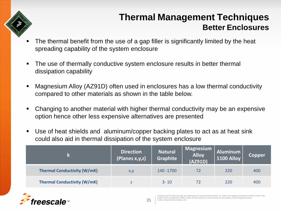
Thermal Management Techniques Better Enclosures
The thermal benefit from the use of a gap filler is significantly limited by the heat
spreading capability of the system enclosure
The use of thermally conductive system enclosure results in better thermal
dissipation capability
Magnesium Alloy (AZ91D) often used in enclosures has a low thermal conductivity
compared to other materials as shown in the table below.
Changing to another material with higher thermal conductivity may be an expensive
option hence other less expensive alternatives are presented
Use of heat shields and aluminum/copper backing plates to act as at heat sink
could also aid in thermal dissipation of the system enclosure
k
Direction (Planes x,y,z)
Natural Graphite
Magnesium Alloy
(AZ91D)
Aluminum 1100 Alloy
Copper
Thermal Conductivity (W/mK) x,y 140 -1700 72 220 400
Thermal Conductivity (W/mK) z 3- 10 72 220 400

TM 22
Freescale and the Freescale logo are trademarks of Freescale Semiconductor, Inc. ARM is the registered trademark of ARM Limited. ARM
Cortex™-A9 is a trademark of ARM Limited. All other product or service names are the property of their respective owners.
© 2012 Freescale Semiconductor, Inc.
Thermal Management Techniques Component Placement
Designers also need to consider the impact of other components on the system board due to their heat generating capacity
Board population density influences thermal performance of the package and should be modeled accordingly. If the devices are very close the power consumed should be part of the thermal design power budget that needs to be modeled
PCB’s with a high density of high power component population experiences a significantly higher rise in temperature relative to the board being populated with a single high power component
Some heat generating devices have to be in close proximity to each other for signal integrity and layout concerns such as the DDR memories hence there is no easy solution around this problem
Designers should however, consider all components and evaluate their placements on the PCB and location with respect to the final form factor housing. Ideally high power devices should not be placed in close proximity to ensure effective thermal dissipation
Details of such placement recommendations are not in the scope of this report however please refer to examples of component placements in Appendix E

TM 23
Freescale and the Freescale logo are trademarks of Freescale Semiconductor, Inc. ARM is the registered trademark of ARM Limited. ARM
Cortex™-A9 is a trademark of ARM Limited. All other product or service names are the property of their respective owners.
© 2012 Freescale Semiconductor, Inc.
Typically more than 80% of the heat generated by a high power component is dissipated
through the system board, when no thermal solution is implemented on the top of the package.
This indicates that the primary heat path is from junction to the board
Under-fill
It is common industrial practice doing under-fill for the key components in to improve the
mechanical strength.
Further thermal improvement can be achieved using the board level under-fill by reducing
junction-to board thermal resistance
Increased PCB Metallization
Increase the heat dissipation (reducing thermal resistance) can also be achieved by
increasing the metallization in the system board. Copper ground layers should be added as
part of the board thermal solution.
Details are provided on the PCB stack up of the Freescale SDP Board used in thermal
simulations in the next section of this document
More Thermal Attach Points
Special care should also be taken in design PCB thermal attach points which allow heat
from the high power component or attached heat spreader to be effectively dissipated.
EMI shields are often used for thermal attach points to the PCB
Thermal Management Techniques
Board Design
TM 24
Freescale and the Freescale logo are trademarks of Freescale Semiconductor, Inc. ARM is the registered trademark of ARM Limited. ARM
Cortex™-A9 is a trademark of ARM Limited. All other product or service names are the property of their respective owners.
© 2012 Freescale Semiconductor, Inc.
Content
• Overview
• Thermal Management Concepts
• Thermal Attributes
• Thermal Simulations
• Software Thermal Management Techniques
• Recommendations /Conclusion
• Appendix/References

25 TM
Freescale and the Freescale logo are trademarks of Freescale Semiconductor, Inc. ARM is the registered trademark of ARM Limited. ARM
Cortex™-A9 is a trademark of ARM Limited. All other product or service names are the property of their respective owners.
© 2012 Freescale Semiconductor, Inc.
i.MX 6Dual/6Quad Thermal Characteristics
Rating Board Type Symbol No Lid Lid Unit
Junction to Ambient
Natural Convection
Single layer board
(1s) R JA 31 24 °C/W
Junction to Ambient
Natural Convection
Four layer board
(2s2p) R JA 22 15 °C/W
Junction to Ambient
(@200 ft/min)
Single layer board
(1s) R JA 24 17 °C/W
Junction to Ambient
(@200 ft/min)
Four layer board
(2s2p) R JA 18 12 °C/W
Junction to Board R JB 12 5.0 °C/W
Junction to Case (Top) R JCtop < 0.1 1.0 °C/W
1. Junction-to-Ambient Thermal Resistance determined per JEDEC JESD51-3 and JESD51-6. Thermal test board meets
JEDEC specification for this package.
2. Junction-to-Board thermal resistance determined per JEDEC JESD51-8. Thermal test board meets JEDEC
specification for the specified package.
3. Junction-to-Case at the top of the package determined using MIL-STD 883 Method 1012.1. The cold plate temperature
is used for the case temperature. Reported value includes the thermal resistance of the interface layer.
Table of Thermal Resistance Data
Refer to the i.MX 6Dual/6Quad Applications Processors datasheet for the latest thermal characteristics
Device: i.MX 6Dual/6Quad
Package: 625 21 x 21 mm FC-
PBGA
Pitch: 0.8 mm
Die Size: 7.2 x 7.2 mm

TM 26
Freescale and the Freescale logo are trademarks of Freescale Semiconductor, Inc. ARM is the registered trademark of ARM Limited. ARM
Cortex™-A9 is a trademark of ARM Limited. All other product or service names are the property of their respective owners.
© 2012 Freescale Semiconductor, Inc.
Thermal Models
A validated thermal model – both at system and package levels – can significantly
reduce the thermal design cycle and time-to-market
The customer must create system level simulations to gain more accurate thermal
results for the application setup
Package Model
From a package perspective the model requires four blocks: die, solder/underfill,
substrate, and solder/air.
The solder/underfill and solder/air require orthotropic material properties because
the conductivities are direction dependant.
In the out-of-plane direction (z-axis) the solder balls increase the conduction
through these layers.
In the in-plane (x-axis and y-axis) direction the bulk conductivities of the underfill
or air dominate.
The solder/air layer would be modeled with the same footprint as the substrate
The solder/underfill layer would be modeled the same size as the die
The other two volumes, exposed die and substrate, have isotropic material properties

TM 27
Freescale and the Freescale logo are trademarks of Freescale Semiconductor, Inc. ARM is the registered trademark of ARM Limited. ARM
Cortex™-A9 is a trademark of ARM Limited. All other product or service names are the property of their respective owners.
© 2012 Freescale Semiconductor, Inc.
Thermal Models
Heat is generated in the circuitry, which is located at the Silicon (die) to Underfill
interface. The heat travels along two principal paths:
Top of the die or
Substrate into the printed circuit board (PCB)
Heat is then removed from all exposed surfaces by convection and radiation.
Figure shows a representation of
the three-dimensional heat path

TM 28
Freescale and the Freescale logo are trademarks of Freescale Semiconductor, Inc. ARM is the registered trademark of ARM Limited. ARM
Cortex™-A9 is a trademark of ARM Limited. All other product or service names are the property of their respective owners.
© 2012 Freescale Semiconductor, Inc.
Thermal Models
Component Material Kx [w/m*k] Ky [w/m*k] Kz [w/m*k]
Die lid interface Compound 2 2 2
Die Silicon 117 117 117
Bumps and underfill Compound 0.6 0.6 5.3
Substrate Compound 33 33 0.8
Solder and air Compound 0.034 0.034 13.9
Solder & air
Substrate
Bumps and under fill
Die Die lid interface
i.MX 6Dual/6Quad 21x21 FCBGA
i.MX 6Dual/6Quad
Thermal Conductivity

TM 29
Freescale and the Freescale logo are trademarks of Freescale Semiconductor, Inc. ARM is the registered trademark of ARM Limited. ARM
Cortex™-A9 is a trademark of ARM Limited. All other product or service names are the property of their respective owners.
© 2012 Freescale Semiconductor, Inc.
Thermal Models
Thermal Modeling
Thermal models can be created which can account for the following system attributes:
Board size and Enclosure dimensions and materials
Boundary & environmental conditions (natural convection and forced
convection)
Heat spreaders and lid materials (Al, Cu, Graphite or Ceramic)
Interface materials (DowCorning 1-4174)
Heat sinks
Thermal Modeling Tools
Thermal simulation tools can be used to provide IC thermal models that can be
integrated with product thermal models to obtain a complete system model. The
primary thermal modeling tools used by Freescale are listed below:
ANSYS Icepak
Mentor V3.2 FloTHERM 9.2
Thermal Models for i.MX 6Dual/6Quad SoC can be made available on request.

TM 30
Freescale and the Freescale logo are trademarks of Freescale Semiconductor, Inc. ARM is the registered trademark of ARM Limited. ARM
Cortex™-A9 is a trademark of ARM Limited. All other product or service names are the property of their respective owners.
© 2012 Freescale Semiconductor, Inc.
Content
• Overview
• Thermal Management Concepts
• Thermal Attributes
• Thermal Simulations
• Software Thermal Management Techniques
• Recommendations /Conclusion
• Appendix/References

TM 31
Freescale and the Freescale logo are trademarks of Freescale Semiconductor, Inc. ARM is the registered trademark of ARM Limited. ARM
Cortex™-A9 is a trademark of ARM Limited. All other product or service names are the property of their respective owners.
© 2012 Freescale Semiconductor, Inc.
Thermal Simulations
Although this particular tablet simulation may not fit all customer applications, it does demonstrate the benefits of various thermal solutions and guidelines on when such solutions are required
Freescale recommends that customers should perform system level simulations to gain more accurate thermal results for their specific application
The simulation results use the i.MX 6Dual/6Quad 21x21 FCBGA in both the non-lidded and the lidded package
To better account for customer application use cases the simulation results also included other high power heat generating components such as the DDR3 memory and the LCD
Simulations were limited to use cases of continuous 2W and 5W power consumption by the i.MX 6Dual/6Quad SoC
This section provides a summary of the thermal simulations performed on an example
tablet model. The intent of the simulations are to illustrate some of the thermal
management techniques detailed in the previous sections.

32 TM
Freescale and the Freescale logo are trademarks of Freescale Semiconductor, Inc. ARM is the registered trademark of ARM Limited. ARM
Cortex™-A9 is a trademark of ARM Limited. All other product or service names are the property of their respective owners.
© 2012 Freescale Semiconductor, Inc.
Geometry of Simplified Thermal Model
21x21 FC-BGA i.MX 6Quad
Memory
Batteries
Graphite
Spreader

TM 33
Freescale and the Freescale logo are trademarks of Freescale Semiconductor, Inc. ARM is the registered trademark of ARM Limited. ARM
Cortex™-A9 is a trademark of ARM Limited. All other product or service names are the property of their respective owners.
© 2012 Freescale Semiconductor, Inc.
Thermal Simulation Details
Simulation Attribute Simulated Value
Enclosure Dimensions [mm] 220x150x20
System Orientation Horizontal (Normal to Z-direction)
Gravity 9.81 m/s2, Negative Z direction
Simulated Heat Transfer Modes Steady-state, Convection, Conduction, Radiation
Ambient condition 25C, Atmospheric pressure
PCB Dimensions [mm] 127x43x1.6
Box size [mm] 191x127x10
Air Flow velocity Natural Convection
Thermal Model Tablet thermal model using the Freescale SDP PCB
board (8 Layers) and components including DDR3
memory and LCD display
Main Processor i.MX 6Dual/6Quad 21x21 FCBGA in both the non-
lidded and the lidded package
34 TM
Freescale and the Freescale logo are trademarks of Freescale Semiconductor, Inc. ARM is the registered trademark of ARM Limited. ARM
Cortex™-A9 is a trademark of ARM Limited. All other product or service names are the property of their respective owners.
© 2012 Freescale Semiconductor, Inc.
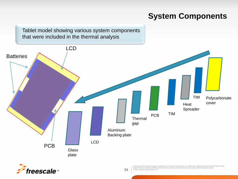
System Components
LCD
Batteries
PCB
Polycarbonate
cover
TIM
Heat
Spreader
PCB Thermal
gap
Aluminum
Backing plate
LCD
Glass
plate
TIM
Tablet model showing various system components
that were included in the thermal analysis

TM 35
Freescale and the Freescale logo are trademarks of Freescale Semiconductor, Inc. ARM is the registered trademark of ARM Limited. ARM
Cortex™-A9 is a trademark of ARM Limited. All other product or service names are the property of their respective owners.
© 2012 Freescale Semiconductor, Inc.
System Components
Table model showing thermal conductivity of various system components
that were included in the thermal analysis
Thermal Conductivity (W/m K)
Item Components Material X Y Z Enclosure Polycarbonate 0.2 0.2 0.2
Battery Compound 20 20 20
PCB Compound Calculated Calculated Calculated
i.MX 6Dual/6Quad
Solder and air Compound 0.034 0.034 13.9
Substrate Compound 32.9 32.9 0.81
Bump & Underfill Compound 0.6 0.6 5.3
Die Silicon 117 117 117
Die lid interface Compound 2 2 2
Lid Copper 389 389 389
Spreader Copper/Graphite 389/600 389/600 389/3.5
TIM Compound 16 16 16
LCD
LCD screen Glass 1 1 1
LCD circuit Compound 125 125 125
Glass plate Glass 1 1 1
Thermal gap pad Compound 2.4 2.4 0.6
Backing plate Aluminum 201 201 201

TM 36
Freescale and the Freescale logo are trademarks of Freescale Semiconductor, Inc. ARM is the registered trademark of ARM Limited. ARM
Cortex™-A9 is a trademark of ARM Limited. All other product or service names are the property of their respective owners.
© 2012 Freescale Semiconductor, Inc.
Simulation Details PCB Components and Stack Up
Power consumption of components on Freescale SABRE SDP board, Rev B
Additional power source : LCD screen – 3W
# Part Assembly
name Location Power [W] 1 IMX6 U1 Up 5W and 2W
2 DDR x 4 U2,U3,U4,U5 Up/Down 0.26
3 QFN5X3 U18 Up 0.0015
4 QFN56 U8 Up 0.1
5 XTAL Y500 Down 0.01
6 MODULE_AH U19 Up 0.15
7 QFN48 U516 Down 0.08
8 BGA196 U512 Down 0.66
9 BAROMETER U21 Up 0.005
10 MAX8903 U502 Down 0.25
11 MAX8815 U6 Up 0.25
12 Compass U20 Up 0.001
13 PMIC U8 Up 0.5
Layer Type
0.50 mils
L1 TOP copper+plating 1.78 mils
dielectric thickness 3.50 mils
L2 GND Plane 1 copper 1.30 mils
dielectric thickness 6.00 mils
L3 Internal 1 copper 1.30 mils
dielectric thickness 6.50 mils
L4 Power 1 copper 1.30 mils
dielectric thickness 18.00 mils
L5 Power 4 copper 1.30 mils
dielectric thickness 6.50 mils
L6 Internal 2 copper 1.30 mils
dielectric thickness 6.00 mils
L7 GND Plane 2 copper 1.30 mils
dielectric thickness 3.50 mils
L8 ? copper 1.30 mils
L9 ? copper 1.30 mils
L10 Bottom copper+plating 1.78 mils
PCB Stack Up
Thickness (mil)
Top side solder mask
L8
Top Solder Mask 0.50 mils

37 TM
Freescale and the Freescale logo are trademarks of Freescale Semiconductor, Inc. ARM is the registered trademark of ARM Limited. ARM
Cortex™-A9 is a trademark of ARM Limited. All other product or service names are the property of their respective owners.
© 2012 Freescale Semiconductor, Inc.
Simulation Details
PCB Bottom View
Copper or
Graphite
Heat spreader
i.MX 6Dual/6Quad
DDR3
Memories
Thermal gap
PCB Top View

TM 38
Freescale and the Freescale logo are trademarks of Freescale Semiconductor, Inc. ARM is the registered trademark of ARM Limited. ARM
Cortex™-A9 is a trademark of ARM Limited. All other product or service names are the property of their respective owners.
© 2012 Freescale Semiconductor, Inc.
Thermal Simulation Results
i.MX 6Dual/6Quad
reaches a temperature of 80 ˚ C
Simulated i.MX 6Dual/6Quad Power
i.MX 6Dual/6Quad
reaches a temperature of 100 ˚ C Power = 5 W
Power = 2 W
LCD Temp 80 ˚ C
LCD Temp 70 ˚ C
Note : Colors denote the relative temperature and not absolute

TM 39
Freescale and the Freescale logo are trademarks of Freescale Semiconductor, Inc. ARM is the registered trademark of ARM Limited. ARM
Cortex™-A9 is a trademark of ARM Limited. All other product or service names are the property of their respective owners.
© 2012 Freescale Semiconductor, Inc.
Thermal Simulation Results
i.MX 6Dual/6Quad
Package Configuration
Heat Spreader Option
(Assumes entire PCB dimension coverage)
Max Power (W) (To maintain 85Deg C within the
enclosure and <=105Deg Tj on die)
Un-lidded None 2.3
Lidded None 3.5
Un-lidded Graphite
(eGraph SS600 0.127mm, TIM K = 2 W/m K )
3.6
Un-lidded Graphite
(eGraph SS500 0.127mm, TIM K = 17 W/m K )
5.6
Un-lidded Copper
(0.2 mm, TIM K = 17 W/m K )
4.6
Un-lidded Copper
(0.6 mm, TIM K = 17 W/m K )
5.7
Heat Spreader Advantages
The goal of these simulations was to determine what is the maximum processor power to maintain 85Deg C within the enclosure and <=105Deg C Tj on the die, with different thermal management techniques applied. Various models were created that varied the package lid options as well as the heat spreader to be used in the tablet.
The results show that using a heat spreader increases the thermal design power and hence
allows running higher power consuming applications within the same thermal envelope

TM 40
Freescale and the Freescale logo are trademarks of Freescale Semiconductor, Inc. ARM is the registered trademark of ARM Limited. ARM
Cortex™-A9 is a trademark of ARM Limited. All other product or service names are the property of their respective owners.
© 2012 Freescale Semiconductor, Inc.
Thermal Simulation Results
Heat Spreader Options
Max Power (W) (To maintain 85Deg C within the enclosure and <=105Deg Tj on die)
30% PCB
Coverage Spreader
dimensions:
43x37mm
55% PCB
Coverage Spreader dimensions:
43x71mm
100% PCB
Coverage Spreader dimensions:
43x127mm
Graphite (eGRAF SS500 Thickness : 0.6mm, TIM K = 17
W/m K )
4.0 4.7 5.6
Graphite (eGRAF SS400 Thickness : 0.6mm, TIM K = 17
W/m K )
4.0 4.7 5.6
Copper (K= 389 Thickness : 0.6mm, TIM K = 17 W/m K )
3.9 4.5 5.7
Copper (K= 389 Thickness : 0.2mm, TIM K = 17 W/m K )
2.9 3.7 4.6
Heat Spreader Dimensions
The goal of these simulations was to determine what is the maximum processor power with
different heat spreader dimensions to be used in the tablet. The table below shows results of
different heat spreaders with varying dimensions including the spreader thickness. The TIM
used had a thermal conductivity K = 17 W/m K
The results show that increasing the heat spreader coverage and
thickness increases the thermal design power and hence allows running
higher power consuming applications within the same thermal envelope

TM 41
Freescale and the Freescale logo are trademarks of Freescale Semiconductor, Inc. ARM is the registered trademark of ARM Limited. ARM
Cortex™-A9 is a trademark of ARM Limited. All other product or service names are the property of their respective owners.
© 2012 Freescale Semiconductor, Inc.
Thermal Simulation Results
Thermal Interface Material (TIM)
Max Power (W) (To maintain 85Deg C within the enclosure and <=105Deg Tj on die)
30% PCB Coverage Spreader dimensions:
43x37mm
55% PCB Coverage Spreader dimensions:
43x71mm
100% PCB Coverage Spreader dimensions:
43x127mm
TIM K = 2 W/m K (eGRAF SS500 Thickness : 0.6mm)
3.8 4.4 5.2
TIM K = 2 W/m K (eGRAF SS400 Thickness : 0.6mm)
3.8 4.4 5.1
TIM K = 17 W/m K (eGRAF SS500 Thickness : 0.6mm)
4.0 4.7 5.6
TIM K = 17 W/m K (eGRAF SS400 Thickness : 0.6mm)
4.0 4.7 5.6
Thermal Interface Material Selection
The goal of these simulations was to determine what is the maximum processor power with
different thermal interface materials to be used in the tablet. The table below shows results of
different heat spreaders with varying dimensions including the spreader thickness
The results show that increasing the thermal conductivity of the TIM does
marginally increase the thermal design power which is aided by increased
thermal conductivity and dimensions of the heat spreader

TM 42
Freescale and the Freescale logo are trademarks of Freescale Semiconductor, Inc. ARM is the registered trademark of ARM Limited. ARM
Cortex™-A9 is a trademark of ARM Limited. All other product or service names are the property of their respective owners.
© 2012 Freescale Semiconductor, Inc.
Thermal Interface Comparisons
Thermally Conductive
Silicone
Red Copper:
401W/(m·K)
Double Sided
adhesive tape
Double faced adhesive tape is
not an effective thermal interface
Thermally Conductive Silicone is a better
interface medium resulting in lower
temperatures similar to the lidded
package
For the same use case run on the Freescale i.MX6Q SD REVB board the lid temperature
was approximately 10 degrees cooler using the higher thermal conductivity thermal silicone
grease than the double faced thermal adhesive tape

TM 43
Freescale and the Freescale logo are trademarks of Freescale Semiconductor, Inc. ARM is the registered trademark of ARM Limited. ARM
Cortex™-A9 is a trademark of ARM Limited. All other product or service names are the property of their respective owners.
© 2012 Freescale Semiconductor, Inc.
Thermal Simulations Power Transient Profile
Power Vs. Temperature
Additional simulations were performed with the Tablet model using an example power profile. This
was used to prove that short bursts of intensive processing followed by long intervals of the in idle
can automatically regulate the heat without much external intervention.
Other power contributors : PCB – 1.5W constant, 7” LCD – 1W constant, LPDDR (max power)– 0.65W
Power Profile
IMX6x 4xA9 @1GHz Temp vs. Power
0
1
2
3
4
5
6
0 20 40 60 80 100 120 140
Temp [oC]
Pw
er
[W]
Leakage
Dynamic
Total Pow er
IMX6 Power Profile
0
0.1
0.2
0.3
0.4
0.5
0.6
0.7
0.8
0.9
1
1.1
0 15 30 45 60 75 90 105 120 135 150 165 180 195 210 225 240 255 270 285 300
Time [sec]
Po
wer M
ult
ipli
er

44 TM
Freescale and the Freescale logo are trademarks of Freescale Semiconductor, Inc. ARM is the registered trademark of ARM Limited. ARM
Cortex™-A9 is a trademark of ARM Limited. All other product or service names are the property of their respective owners.
© 2012 Freescale Semiconductor, Inc.
Power Profile Junction Temperature Variation with Time
25
30
35
40
45
50
55
60
65
0 500 1000 1500 2000 2500 3000
Time (s)
T j
un
cti
on
(C
)
Tj (imx6x)
Example Duty cycle considered:
• 5s at max power, 25s at of 80% of max power, 135 s at max power/2 and 135 s at low power
• System eventually reaches a steady state over time
T ambient = 25 C
Junction temperature variation
is the same for all 3 orientations
(gravity in negative x, y, and z
directions)
Tablet Model
TM 45
Freescale and the Freescale logo are trademarks of Freescale Semiconductor, Inc. ARM is the registered trademark of ARM Limited. ARM
Cortex™-A9 is a trademark of ARM Limited. All other product or service names are the property of their respective owners.
© 2012 Freescale Semiconductor, Inc.
Content
• Overview
• Thermal Management Concepts
• Thermal Attributes
• Thermal Simulations
• Software Thermal Management Techniques
• Recommendations /Conclusion
• Appendix/References

TM 46
Freescale and the Freescale logo are trademarks of Freescale Semiconductor, Inc. ARM is the registered trademark of ARM Limited. ARM
Cortex™-A9 is a trademark of ARM Limited. All other product or service names are the property of their respective owners.
© 2012 Freescale Semiconductor, Inc.
Software Thermal Management Techniques
The i.MX 6 series and the i.MX 6Dual/6Quad SoC in particular incorporates several low-power
design techniques, to meet requirements of low-power design, while sustaining high performance
operation when required. Even with these techniques in place managing the heat dissipated needs
to be considered depending on application use case. The more intensive the use case with all major
power contributors active such as the Cortex A9 cores, Graphics Processing Unit (GPU) and the
DDR memories the higher the potential thermal energy that needs to be effectively dissipated.
Software Leverages Hardware
Leveraging features and power saving strategies implemented at the device and micro architectural
level can have a significant impact on thermal demand. Software can take advantage of various
hardware features that allow power optimization thereby managing heat dynamically and reducing
the need for heat spreaders, heat sinks and metal enclosures.
This section focuses specifically on ways to improve thermal performance in by limiting the source of
heat in integrated circuits: power. Although a deep dive into these features are beyond the scope of
this report a few key aspects of chip level power and software thermal management techniques will
be discussed in this section of the document.

47 TM
Freescale and the Freescale logo are trademarks of Freescale Semiconductor, Inc. ARM is the registered trademark of ARM Limited. ARM
Cortex™-A9 is a trademark of ARM Limited. All other product or service names are the property of their respective owners.
© 2012 Freescale Semiconductor, Inc.
Software Thermal Management
Technique HW Support BSP Support Comments
DVFS Yes Yes
Feature implemented in BSP version GA1209
Pre defined set points defined for
frequency and Bus Scaling
Temperature Monitor Yes Yes
Feature implemented in BSP version GA1209
Define thresholds based on temp
sensor readings
Temperature Aware DVFS Yes Yes
Feature implemented in BSP version GA1209
Throttle CPU based on temp sensor
readings
Temperature Aware CPU
Pool Management Yes
No
Feature to be implemented in future BSP
release
Offline cores is not supported in
current BSP release
Clock & Power Gating Yes Yes
Feature implemented in BSP version GA1209
Gate clocks and power domains when
not in use
DDR (MMDC) and I/O
Power Optimizations Yes
Yes
Feature implemented in BSP version GA1209
Optimized ODT settings, Auto power
down modes and support for
frequency scaling
GPU Power Management Yes No
Feature to be implemented in future BSP
release
Reduce Core clock frequency,
reducing shader clocks
LDO Full Bypass Yes Yes
Feature implemented in BSP version GA1209 Bypass LDO and use external PMIC.
For full power management features supported please refer to the table in Appendix B
TM 48
Freescale and the Freescale logo are trademarks of Freescale Semiconductor, Inc. ARM is the registered trademark of ARM Limited. ARM
Cortex™-A9 is a trademark of ARM Limited. All other product or service names are the property of their respective owners.
© 2012 Freescale Semiconductor, Inc.
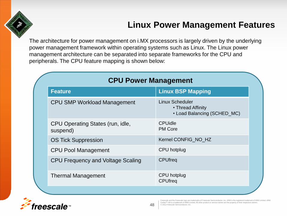
Linux Power Management Features
Feature Linux BSP Mapping
CPU SMP Workload Management Linux Scheduler
• Thread Affinity
• Load Balancing (SCHED_MC)
CPU Operating States (run, idle,
suspend)
CPUidle
PM Core
OS Tick Suppression Kernel CONFIG_NO_HZ
CPU Pool Management CPU hotplug
CPU Frequency and Voltage Scaling CPUfreq
Thermal Management CPU hotplug
CPUfreq
CPU Power Management
The architecture for power management on i.MX processors is largely driven by the underlying
power management framework within operating systems such as Linux. The Linux power
management architecture can be separated into separate frameworks for the CPU and
peripherals. The CPU feature mapping is shown below:

TM 49
Freescale and the Freescale logo are trademarks of Freescale Semiconductor, Inc. ARM is the registered trademark of ARM Limited. ARM
Cortex™-A9 is a trademark of ARM Limited. All other product or service names are the property of their respective owners.
© 2012 Freescale Semiconductor, Inc.
Memory Controller (MMDC) Optimizations (Included in BSP Version GA1209)
When possible, at lower performance use-cases, users should switch to DDR3: DLL off mode, which allows to greatly reduce the DDR frequency and thus disable or reduce termination and reduce the drive strength, which significantly reduces the power consumption of the DDR interface.
Note : Support for drive strength reduction in DLL OFF mode is not supported in the BSP
Transitions between DDR modes such as frequency changing add extra cost and power. Slowing requesters while keeping DDR at full speed may increase total system power.
Cooperative Dynamic Frequency Scaling is implemented in order to keep the system “balanced” i.e. keep system in balance when DDR throughput is equal or slightly higher than total amount of requests generated by all requesters.
Reducing the DDR frequency, while in DDR3: DLL-ON mode may be not efficient, because:
Reduction in DDR frequency will cause bus duty cycle to increase and thus reduces chance of automatic MMDC power saving (place memory into Self Refresh).
Total amount of read/write operation does not change (power is per-operation)
The termination is active longer, though, lowering frequency from 528Mhz to 400MHz or below may enable lowering drive strengths and termination
A good strategy for many types of workload is to combine most activity in bursts (natively possible, for example, for typical multimedia applications, communication, etc.) and run this segment at maximal speed and then switch to DDR3: DLL-OFF mode to support “background activity” (communication, display refresh, etc.)
TM 50
Freescale and the Freescale logo are trademarks of Freescale Semiconductor, Inc. ARM is the registered trademark of ARM Limited. ARM
Cortex™-A9 is a trademark of ARM Limited. All other product or service names are the property of their respective owners.
© 2012 Freescale Semiconductor, Inc.
DDR I/O Power Management (Included in BSP Version GA1209)
On Die Termination
The DRAM Interface power dissipation depends on many variables however proper
termination and drive strength is key for power and thermal performance. Memory and
controllers provide a host of programmable options for the drive strength of the output
buffers and for the on-die termination impedance.
The ideal settings for drive strength and ODT will also depend on the clock frequency
to ensure that inter-symbol interference (ISI) effects are not introduced
An optimized system creates smaller reflections, cleaner edge transitions and overall
lower power dissipation
DDR3 PHY power dissipation decreases significantly as the ODT termination values
programmed into the DDR SDRAM are increased
DDR PHY power is also proportional to bus activity and what type of activity is
happening on the bus (e.g., Read, Write or idle)
Due to the ODT that is active in the DDR PHY during Reads from the DDR SDRAMs,
DDR PHYs typically consume more power during a Read versus a Write when the
data is driven off-chip to the DRAMs.
For more data on ODT savings please refer to the Application note AN4509 i.MX
6Dual/6Quad Power Consumption available on the Freescale Extranet.

TM 51
Freescale and the Freescale logo are trademarks of Freescale Semiconductor, Inc. ARM is the registered trademark of ARM Limited. ARM
Cortex™-A9 is a trademark of ARM Limited. All other product or service names are the property of their respective owners.
© 2012 Freescale Semiconductor, Inc.
DDR I/O Power Management (Included in BSP Version GA1209)
ODT settings shown below:
The highlighted row shows the Freescale recommended ODT setting of 0x11117
that is programmed in the MMDC MPODTCTRL register
0x00007 can save about 40% DDR power compared to strongest setting(0x22227),
but really depends on the customer board layout
Termination requires a lot of care in component-based, embedded applications
Freescale recommends signal integrity analysis be performed to determine the
optimal output drive impedance and ODT values for the specific customer system
Register Setting
(MPODTCTRL)
DDR_ODT
(Ohms)
IMX_ODT
(Ohms)
Comments
0x22227 120 060 Highest Power
consumption
0x11117 120 120 Recommended
0x00007 120 000 Use only if validated on
Board
0x00000 000 000 Not Recommended

TM 52
Freescale and the Freescale logo are trademarks of Freescale Semiconductor, Inc. ARM is the registered trademark of ARM Limited. ARM
Cortex™-A9 is a trademark of ARM Limited. All other product or service names are the property of their respective owners.
© 2012 Freescale Semiconductor, Inc.
DDR I/O Power Management (Included in BSP Version GA1209)
Reducing I/O Power
As we move to wider DDR interfaces with higher clock rates, the power consumed by the DDR
I/O continues to grow significantly. By using peripheral DVFS to lower the DDR clock rate to a
frequency that adapts to memory bus loading, it may be possible to lower the DDR I/O drive
strength at lower frequencies. This particular feature is planned for the next BSP release.
In other cases where the DDR is placed into self-refresh, the DDR I/O can be floated or lowered
to minimum drive allowed by JEDEC.
Modifying the DDR drive strength must be done by code that is executing from a memory region
other than DDR (for example, IRAM).
No access to DDR (including page table walks, cache misses, alternate bus master accesses)
is allowed while the DDR I/O pads are being reconfigured.
Enabling Auto Power Saving
Additional power savings can be achieved by enabling auto power saving mode, which will allow
the DDR memory to automatically enter self-refresh mode when there are no DDR accesses for
a configurable time. The default setting is 1024 clock cycles which can be optimized based on
the customer use case and application
DDR Memory Selection
Consider LPDDR2 over DDR3. Although LPDDR2 may be at a higher price premium, it draws
less power than DDR3 devices. In addition, since LPDDR2 does not have a DLL, eliminating the
complexity of managing DDR3:DLL on and off modes for frequency scaling. DDR3L is also an
available memory choice for further reducing DDR power consumption.

TM 53
Freescale and the Freescale logo are trademarks of Freescale Semiconductor, Inc. ARM is the registered trademark of ARM Limited. ARM
Cortex™-A9 is a trademark of ARM Limited. All other product or service names are the property of their respective owners.
© 2012 Freescale Semiconductor, Inc.
CPU Freq Mechanism (Included in BSP Version GA1209)
To use DVFS, pre defined policies are employed that
govern when to switch between set points in the
application. In the Linux BSP release, there is
operating system support for managing DVFS via
CPUFreq utilities, and is comprised of a driver and one
or more governors. The Linux BSP has a set of
governors that can be used to optimize the DVFS
subsystem based on the needs of the application.
Example governors exist for performance, power,
userspace, and ondemand. The userspace governor
allows applications to control when, specifically, to
move between OPPs. The ondemand governor scales
up when there is high CPU utilization and down when
there is low CPU utilization. The CPUFreq framework
allows applications to subscribe to DVFS change
events.
Please refer to the CPUFreq section of the Linux
kernel documentation for more information.
CPU
operating points
CPUFreq
CPUFreq
Clock Framework Regulator API
Kernel-space - generic
Kernel-space - SOC

TM 54
Freescale and the Freescale logo are trademarks of Freescale Semiconductor, Inc. ARM is the registered trademark of ARM Limited. ARM
Cortex™-A9 is a trademark of ARM Limited. All other product or service names are the property of their respective owners.
© 2012 Freescale Semiconductor, Inc.
CPU Freq mechanism (Included in BSP Version GA1209)
The ARM Frequency (CPUFreq) interactive governor when enabled will auto scale the
CPU frequency according to the CPU loading
The supported ARM CPU frequency and ARM core Voltage (VDDARM_CAP) set points
are available in the i.MX 6Dual/6Quad Data Sheet:
Specifically, when the new target frequency is higher (resulting from moving to a higher set
point), the voltage is increased first, followed by the core frequency.
When the new target frequency is lower (resulting from moving to a lower set point),the
core frequency is reduced first, followed by the voltage reduction
To balance the power saving and performance, the interactive governor can act upon the
CPU Load. The CPU frequency adjustment is determined by the percentage of CPU
loading.
For example, if the CPU loading is about 75%, then the CPU frequency will be
996MHz *75% = 747 MHz ,
Hence the CPU freq driver will adjust the ARM core frequency to the 792 MHz set point

TM 55
Freescale and the Freescale logo are trademarks of Freescale Semiconductor, Inc. ARM is the registered trademark of ARM Limited. ARM
Cortex™-A9 is a trademark of ARM Limited. All other product or service names are the property of their respective owners.
© 2012 Freescale Semiconductor, Inc.
CPU Pool Management
For multi-core systems such as the i.MX 6Dual/6Quad processors, it is possible to add
and remove available cores from the CPU pool
This CPU pool management was originally designed to allow hot-swapping of CPU
boards on multi-core systems without taking the entire system offline
In embedded systems, cores can be removed from the available CPU pool during
periods of low CPU loading or when managing the temperature
The cores removed from the CPU pool can remain in a low-power state or possibly
powered off entirely if the architecture allows
Aggregating the CPU workload onto fewer cores can reduce overhead associated with
threads migrating to different cores and maintaining coherency between the cores
The Linux BSP mapping of this feature is referred to CPU Hotplug and is briefly
described in the following section

TM 56
Freescale and the Freescale logo are trademarks of Freescale Semiconductor, Inc. ARM is the registered trademark of ARM Limited. ARM
Cortex™-A9 is a trademark of ARM Limited. All other product or service names are the property of their respective owners.
© 2012 Freescale Semiconductor, Inc.
CPU Pool Management CPU hotplug
CPU hotplug is a Linux kernel framework that places CPU’s on/offline
CPU hotplug can be used for power savings
The scheduler does not assign processes to CPU offline
The scheduler can add or remove CPU’s by CPU Hotplug
SCHED_MC manages the spread of work load among online CPU’s
CPU hotplug can be utilized for both CPU Pool management as well as Thermal
Management
During system operation as defined thermal thresholds are reached the thermal
driver will remove one of the secondary cores
If the system temperature keeps increasing, the thermal driver will continue to
remove additional cores until only the primary CPU0 core is left running
When the temperature falls back to the safe range, all additional cores that were
removed will be bought back online
Note: CPU hotplug is not currently supported as a mechanism for thermal
management in the current BSP GA release

TM 57
Freescale and the Freescale logo are trademarks of Freescale Semiconductor, Inc. ARM is the registered trademark of ARM Limited. ARM
Cortex™-A9 is a trademark of ARM Limited. All other product or service names are the property of their respective owners.
© 2012 Freescale Semiconductor, Inc.
BUS Frequency Scaling (Included in BSP Version GA1209)
DVFS for ARM and scaling the frequencies of the DDR, AXI, AHB, and IPG bus
clocks can significantly reduce the power consumption
However, due to the reduced operation frequency, the accesses to the DDR take
longer, which increases the power consumption of the DDR I/O and memories
This tradeoff needs to be taken into account for each mode, to quantify the overall
affect on system power.
Algorithms used to scale internal bus frequencies ideally should match the bus
bandwidth required for the current use case. In the absence of bus monitors, it
may be possible to scale bus frequencies based on the activity of bus masters
It is also important to determine, if the system is “memory” bounded or
“processing” bounded in target use cases and different stages of execution within
the use case

TM 58
Freescale and the Freescale logo are trademarks of Freescale Semiconductor, Inc. ARM is the registered trademark of ARM Limited. ARM
Cortex™-A9 is a trademark of ARM Limited. All other product or service names are the property of their respective owners.
© 2012 Freescale Semiconductor, Inc.
BUS Frequency Scaling (Included in BSP Version GA1209)
Enable the BUS freq driver to auto scale the bus frequency utilizing the 4 set points as shown in the table below:
• The BUS freq driver will work in the following manner:
If high speed device clocks are enabled, bus frequency scaling not performed and continue to run at full speed;
If no high speed devices are enabled, but CPU freq is not at lowest set point, run at mid speed;
If no high speed devices are enabled and CPU freq is at the lowest set point, but audio module is enabled, run in the audio bus mode;
If no high speed devices are enabled and CPU freq is at the lowest set point, and audio module is not enabled, run in the low bus mode;
DDR freq (MHz) AXI (MHz) AHB (MHz) Power saved
528 264 132 Full Speed
400 200 133 Mid speed
50 (DLL off) 50 25 Audio bus mode
24 (DLL off) 24 24 Low bus mode

TM 59
Freescale and the Freescale logo are trademarks of Freescale Semiconductor, Inc. ARM is the registered trademark of ARM Limited. ARM
Cortex™-A9 is a trademark of ARM Limited. All other product or service names are the property of their respective owners.
© 2012 Freescale Semiconductor, Inc.
Clock Gating & Power Domain Control (Included in BSP Version GA1209)
Clock Gating
Maintain clock parent/children dependency in clock tree, all drivers need to disable their clocks
when they are not active
The clock driver framework to auto disable all the clocks whose use count is 0. This ensures all
unused clocks are disabled
If aggressive clock gating is utilized (run-fast-and-stop), then Dynamic Frequency Scaling (DFS)
offers little benefit and could actually increase power due to longer bus duty cycles
Power Gating
Power gate unused domains under certain use cases, such as the PU domain when system is
in low power audio mode and system idle mode
The GPUs and VPU are part of the PU power domain, which can be powered off by power
gating their corresponding LDO. The PU domain is managed by GPU/VPU drivers. Support for
this feature is planned for the next BSP Release
The bus freq driver performs this when migrating into low power audio or system idle modes
(For a definition of these low power modes please refer to AN4509 i.MX 6Dual/6Quad Power Consumption
Measurement available on the Freescale Extranet)
The PU domain is automatically restored when the system exits from these two modes
Other domains can be power gated depending on the application use case
TM 60
Freescale and the Freescale logo are trademarks of Freescale Semiconductor, Inc. ARM is the registered trademark of ARM Limited. ARM
Cortex™-A9 is a trademark of ARM Limited. All other product or service names are the property of their respective owners.
© 2012 Freescale Semiconductor, Inc.
Clock Gating & Peripheral Power (Included in BSP Version GA1209)
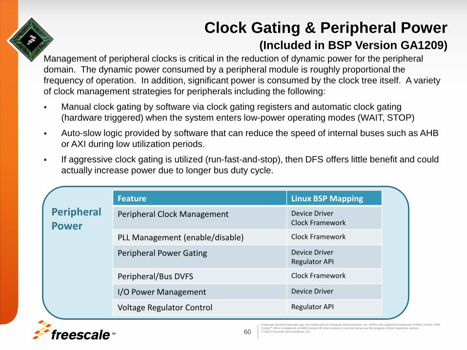
Management of peripheral clocks is critical in the reduction of dynamic power for the peripheral
domain. The dynamic power consumed by a peripheral module is roughly proportional the
frequency of operation. In addition, significant power is consumed by the clock tree itself. A variety
of clock management strategies for peripherals including the following:
Manual clock gating by software via clock gating registers and automatic clock gating
(hardware triggered) when the system enters low-power operating modes (WAIT, STOP)
Auto-slow logic provided by software that can reduce the speed of internal buses such as AHB
or AXI during low utilization periods.
If aggressive clock gating is utilized (run-fast-and-stop), then DFS offers little benefit and could
actually increase power due to longer bus duty cycle.
Feature Linux BSP Mapping
Peripheral Clock Management Device Driver Clock Framework
PLL Management (enable/disable) Clock Framework
Peripheral Power Gating Device Driver Regulator API
Peripheral/Bus DVFS Clock Framework
I/O Power Management Device Driver
Voltage Regulator Control Regulator API
Peripheral Power
TM 61
Freescale and the Freescale logo are trademarks of Freescale Semiconductor, Inc. ARM is the registered trademark of ARM Limited. ARM
Cortex™-A9 is a trademark of ARM Limited. All other product or service names are the property of their respective owners.
© 2012 Freescale Semiconductor, Inc.
PHY and IO Power Control (Included in BSP Version GA1209)
PHY
PHY’s can consume considerable power if the circuits are left enabled
The recommendation is to place all unused PHY’s to the lowest power state such
as SATA, HDMI and PCIe
IO Power
The IOMUX pads should be set to lowest power setting when system is in suspend
mode
All unnecessary PU/PD resistors should be disabled
Set DDR type IO pads to CMOS mode if possible, specifically for the RGMII
segment
Suspend code is run in IRAM allowing for lower leakage on DDR I/O pads by
lowering the drive strengths
Note : In the current BSP release the DDR IO is set to CMOS mode only in DSM mode

TM 62
Freescale and the Freescale logo are trademarks of Freescale Semiconductor, Inc. ARM is the registered trademark of ARM Limited. ARM
Cortex™-A9 is a trademark of ARM Limited. All other product or service names are the property of their respective owners.
© 2012 Freescale Semiconductor, Inc.
Thermal Monitor & Protection (Included in BSP Version GA1209 )
Overview
The temperature sensor module (TEMPMON) implements a temperature
sensor/conversion function based on a temperature-dependent voltage to time
conversion. A self-repeating mode can also be programmed which executes a
temperature sensing operation based on a programmed delay
The module features an alarm function that can raise an interrupt signal if the
temperature is above a specified threshold. The current BSP release implements
the interrupt signal to notify a system reboot for critical temperature
CPUFreq works with the temperature monitor driver to ensure that the frequency of
the core is lowered when the die temperature is above the specified limit. The
current BSP release supports CPUFreq
Temperature
Monitor driver
CPUFreq

TM 63
Freescale and the Freescale logo are trademarks of Freescale Semiconductor, Inc. ARM is the registered trademark of ARM Limited. ARM
Cortex™-A9 is a trademark of ARM Limited. All other product or service names are the property of their respective owners.
© 2012 Freescale Semiconductor, Inc.
Thermal Monitor & Protection (Included in BSP Version GA1209 )
Software Thermal Driver
Software can use this module to monitor the on-die temperature and take appropriate actions such
as throttling back the core frequency or off lining a core when a temperature interrupt is set. The
thermal driver requires calibrated parts and reads the calibration data from the fuses.
The thermal driver implements three threshold points for temperature – critical, hot and active
Critical : when the measured on die temperature exceeds the critical threshold → reboot the
system (protection mechanism to prevent damage). For the Linux BSP GA1209 Release this
threshold is programmed to 100 ˚ C. The thermal driver checks the temperature, and only
permits the system to boot up if the temperature is below 80 ˚ C.
Hot : when the on die temperature exceeds the hot threshold → reduce the frequency. If the
temperature keeps increasing, continue to reduce the frequency using CPU Freq. For the Linux
BSP GA1209 Release this threshold is programmed to 90 ˚ C.
Active: when the on die temperature drops below the active threshold → restore the previous
CPU Freq driver determined maximum ARM core frequency. For the Linux BSP GA1209
Release this threshold is programmed to 80˚C.
The number of thresholds and respective actions for each, is completely defined in software and
can hence be easily modified to cater to the customer specific requirements
The thermal driver works with CPU Freq mechanism. In future BSP releases CPU hotplug will also
be supported as a cooling device

TM 64
Freescale and the Freescale logo are trademarks of Freescale Semiconductor, Inc. ARM is the registered trademark of ARM Limited. ARM
Cortex™-A9 is a trademark of ARM Limited. All other product or service names are the property of their respective owners.
© 2012 Freescale Semiconductor, Inc.
DFS Based on CPU Temperature
As an example for a given CPU loading the CPU freq set point is 996MHz and the temperature
exceeds the cpu_hot threshold. The CPU thermal driver will adjust the CPU Freq governor’s
cpu_max_freq to the next lower set point (792MHz). As a result, the CPU frequency is
automatically lowered below the cpu_max_freq
If the CPU temperature keeps increasing, the thermal driver will again automatically lower the
cpu_max_freq to the next set point (396MHz)
The number of thresholds and respective actions for each, is completely defined in
software
CPU loading
CPU freq
MHz
996
792
396
loading1 loading2 loading3
cpu_max_freq = 396
CPU loading
CPU freq
MHz
996
792
396
loading1 loading2 loading3
cpu_max_freq cpu_max_freq = 996
cpu_max_freq = 792
cpu temp > cpu_hot
Graph shows CPU
frequency changing as
the loading increases
without the thermal
driver Graph shows CPU frequency
changing as the loading
increases with the thermal
driver enabled

TM 65
Freescale and the Freescale logo are trademarks of Freescale Semiconductor, Inc. ARM is the registered trademark of ARM Limited. ARM
Cortex™-A9 is a trademark of ARM Limited. All other product or service names are the property of their respective owners.
© 2012 Freescale Semiconductor, Inc.
GPU Thermal Management
Memory or Processing Bounded
For high performance multimedia use cases such as 3D playback, thermal and power
management of the GPU3D core become essential
Such use cases not only utilize the GPU but are also very DDR memory intensive hence
increasing the total system power (DDR + IO)
It is important to determine, if the system is “memory” bounded or “processing” bounded
in target use cases that utilize multiple high performance IP . This is also required for
different stages of execution within the use case.
This determination assists in identifying where the power and heat is being generated
hence allows users to throttle the correct master
In theory, run fast and idle is the best strategy as graphics workloads can be variably
sensitive to render latency
The DVFS strategy for CPU and GPU/VPU/IPU should be “run fast” if “processing”
bounded case and frequency downscaling for processing modules in “memory” bounded
cases

TM 66
Freescale and the Freescale logo are trademarks of Freescale Semiconductor, Inc. ARM is the registered trademark of ARM Limited. ARM
Cortex™-A9 is a trademark of ARM Limited. All other product or service names are the property of their respective owners.
© 2012 Freescale Semiconductor, Inc.
GPU Thermal Management
The GPU software driver enables all the power management techniques/features implemented in GPU3D design and the driver does reasonable management of these features
Internal Clock Gating
GPU3D facilitates efficient power/clock management policy internally:
Fine granular clock gating system that efficiently gate clocks for many modules that temporarily are not active (This feature is enabled by default in the software driver that is part of the current BSP release)
It has monitors and software may control internal clock rate modulation
GPU Frequency Scaling
For further temperature reduction users can control the GPU performance and in particular the frequency at which the GPU and its sub components run
The thermal driver can inform the GPU to do perform frequency scaling when the device temperature reaches a certain threshold
GPU can be programmed to scale all of its clocks such as the AXI, shader and core clock. Depending on the use case the impact of scaling various internal GPU clocks varies, since not all use cases will require all sub components of the GPU. A general understanding of the profile of the power intensive use case assists in frequency scaling the correct sub component
This temperature aware GPU frequency scaling feature will be incorporated in the post GA BSP release

TM 67
Freescale and the Freescale logo are trademarks of Freescale Semiconductor, Inc. ARM is the registered trademark of ARM Limited. ARM
Cortex™-A9 is a trademark of ARM Limited. All other product or service names are the property of their respective owners.
© 2012 Freescale Semiconductor, Inc.
LDO Bypass Mode
Full Digital Bypass Mode
The i.MX6 series power management system was built under assumption that in typical
applications the single (and simple) shared power supply will be used for ARM core domain
and SoC domain
The combined load gains some efficiency, especially in low power modes and can save
BOM costs significantly
In high power mode (highest DVS set-point) the internal regulators (LDOs) are bypassed
and have a very small residual resistance ( like regular power gating FETs )
Thus, using LDO bypass, customers in certain applications may implement a regular DVS
based system using a software controllable external PMIC
While i.MX6 is in low power mode the external PMIC could be switched from normal (PWM)
regulation to some of its power saving modes and reduce the voltage drop over internal
LDOs
i.MX6 has dedicated signal to control external DCDC/PMIC switching between normal
operations (PWM regulation) and low power modes
Potential power savings in LDO Bypass mode which will translate directly to thermal
savings
The BSP already supports full bypass for customers that have a programmable PMIC such
as PF0100

TM 68
Freescale and the Freescale logo are trademarks of Freescale Semiconductor, Inc. ARM is the registered trademark of ARM Limited. ARM
Cortex™-A9 is a trademark of ARM Limited. All other product or service names are the property of their respective owners.
© 2012 Freescale Semiconductor, Inc.
Content
• Overview
• Thermal Management Concepts
• Thermal Attributes
• Thermal Simulations
• Software Thermal Management Techniques
• Recommendations /Conclusion
• Appendix/References
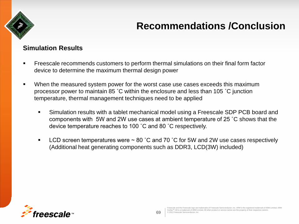
TM 69
Freescale and the Freescale logo are trademarks of Freescale Semiconductor, Inc. ARM is the registered trademark of ARM Limited. ARM
Cortex™-A9 is a trademark of ARM Limited. All other product or service names are the property of their respective owners.
© 2012 Freescale Semiconductor, Inc.
Recommendations /Conclusion
Simulation Results
Freescale recommends customers to perform thermal simulations on their final form factor
device to determine the maximum thermal design power
When the measured system power for the worst case use cases exceeds this maximum
processor power to maintain 85 ˚C within the enclosure and less than 105 ˚C junction
temperature, thermal management techniques need to be applied
Simulation results with a tablet mechanical model using a Freescale SDP PCB board and
components with 5W and 2W use cases at ambient temperature of 25 ˚C shows that the
device temperature reaches to 100 ˚C and 80 ˚C respectively.
LCD screen temperatures were ~ 80 ˚C and 70 ˚C for 5W and 2W use cases respectively
(Additional heat generating components such as DDR3, LCD(3W) included)

TM 70
Freescale and the Freescale logo are trademarks of Freescale Semiconductor, Inc. ARM is the registered trademark of ARM Limited. ARM
Cortex™-A9 is a trademark of ARM Limited. All other product or service names are the property of their respective owners.
© 2012 Freescale Semiconductor, Inc.
Recommendations /Conclusion Graphite Heat Spreaders
Various passive thermal management techniques were presented. The most effective from a
performance aspect is the graphite heat spreader
Simulation results show that increasing the heat spreader coverage and thickness increases
the thermal design power and allows running higher power consuming applications within the
same thermal envelope
Simulation results showed that with the heat spreader the non lidded package heat dissipation
was similar to a lidded package if the heat spreader was applied properly
There was minimal impact on results due to the change from copper to graphite heat spreader
as the main contributor to the temperature decrease was the spreader thickness and
dimensions
The graphite spreader reduced the overall temperature gradient within the device and the
enclosure touch temperature
Increasing the thermal conductivity of the thermal gap filler and interface material marginally
improved the system heat dissipation
Simulations have shown that for 5.6 W and above, incorporation of a spreader alone will not
suffice, and additional thermal management techniques will be required to hold the junction
temperatures within specification
TM 71
Freescale and the Freescale logo are trademarks of Freescale Semiconductor, Inc. ARM is the registered trademark of ARM Limited. ARM
Cortex™-A9 is a trademark of ARM Limited. All other product or service names are the property of their respective owners.
© 2012 Freescale Semiconductor, Inc.
Recommendations /Conclusion
Software Thermal Management
The i.MX 6Dual/6Quad SoC incorporates several low-power design techniques and leveraging features
and power saving strategies implemented at the device and micro architectural level can have a
significant impact on the thermal demand. Heat in an embedded system is a by product of power and the
best way to generate less heat is to consume less power.
Software can take advantage of various hardware features that allow power optimization thereby
managing heat dynamically and reducing the need for heat spreaders, heat sinks and metal enclosures
Various software thermal management techniques were presented that enable customers to remain within
the defined thermal enveloped
A summary of the power management framework within operating systems such as Linux was presented
in the context of thermal management. These features such as Temperature Aware DVFS allow throttling
of the CPU frequency to reduce the temperature when above the software defined temperature
thresholds
Significant power and thermal savings have been seen with DDR Controller and memory optimizations
such as On Die Termination
Software features that have been made available in the GA 1209 Linux BSP release have been
highlighted along with additional features planned for future BSP releases

TM 72
Freescale and the Freescale logo are trademarks of Freescale Semiconductor, Inc. ARM is the registered trademark of ARM Limited. ARM
Cortex™-A9 is a trademark of ARM Limited. All other product or service names are the property of their respective owners.
© 2012 Freescale Semiconductor, Inc.
Content
• Overview
• Thermal Management Concepts
• Thermal Attributes
• Thermal Simulations
• Software Thermal Management Techniques
• Recommendations /Conclusion
• Appendix/References

TM 73
Freescale and the Freescale logo are trademarks of Freescale Semiconductor, Inc. ARM is the registered trademark of ARM Limited. ARM
Cortex™-A9 is a trademark of ARM Limited. All other product or service names are the property of their respective owners.
© 2012 Freescale Semiconductor, Inc.
Appendix A - DDR Interface Power Variables 1
Issue Affecting Power Impact

TM 74
Freescale and the Freescale logo are trademarks of Freescale Semiconductor, Inc. ARM is the registered trademark of ARM Limited. ARM
Cortex™-A9 is a trademark of ARM Limited. All other product or service names are the property of their respective owners.
© 2012 Freescale Semiconductor, Inc.
Appendix B i.MX 6Dual/6Quad SoC Power Management Features
Feature Active
SoC Power
Standby
SoC Power
System
Power
LP flavor of 40nm process
Minimized number of LVT transistors
Temperature monitoring and active frequency throttling
ARM DVFS
ARM SRPG (software)
ARM Power Gating (Internal switches)
VPU & GPU3D Power Gating
Well biasing
Clock gating (automatic dynamic and forced)
Integrated PMU (IR drop, efficiency, accuracy)
C4 package (IR drop, thermal)
Independent Power gating of IO supplies
Architecture: L2 cache, Video/Audio/Graphics
acceleration
Architecture: USB, PCIe, SATA, HDMI, LVDS integration
Low power DDR: LPDDR2, LV-DDR3

TM 75
Freescale and the Freescale logo are trademarks of Freescale Semiconductor, Inc. ARM is the registered trademark of ARM Limited. ARM
Cortex™-A9 is a trademark of ARM Limited. All other product or service names are the property of their respective owners.
© 2012 Freescale Semiconductor, Inc.
Appendix C
Thermal Measurement Glossary
For standardized thermal performance values, the thermal performance is determined
per the JEDEC standards.
The thermal performance of a package is typically determined on both a single signal
layer test board (1s) and on a multi-layer test board (2s2p)
A single number is generally used to quantify the temperature rise of the circuitry with
respect to a specified external location. The thermal resistance value, Theta-JX,
where “X” is the external location, is calculated as
The temperature difference between the hottest spot on the circuitry (junction) and
location “X” is divided by the power dissipation in Equation 1
Equation 1 also indicates that Theta-JX (θjx) is used interchangeably with the notation
RθJX. The latter is the official JEDEC notation.
Equation 1
TM 76
Freescale and the Freescale logo are trademarks of Freescale Semiconductor, Inc. ARM is the registered trademark of ARM Limited. ARM
Cortex™-A9 is a trademark of ARM Limited. All other product or service names are the property of their respective owners.
© 2012 Freescale Semiconductor, Inc.
Appendix C
Thermal Measurement Glossary
Theta-JA (RθJA)
Junction to ambient thermal resistance in moving air, Theta-JA (RθJA) is determined
according to EIA/JESD51-6
Theta-JA is also used to represent the junction-to-ambient thermal resistance obtained
on a 2s2p test board in natural convection
This thermal resistance is recommended in applications where the device is
dissipating most of the power, and the device is mounted on a multi-layer board
If airflow is present, the Theta-JA values can be used as a first estimate to determine
if the package will function without a heat sink
Theta-JC (RθJC) Junction-to-case thermal resistance, Theta-JC (RθJC) is determined using the basic
cold plate guidelines described by MIL-STD 883D, Method 1012.15 as the reference
specification
Normally Theta-JC is measured with a thin layer of thermal grease
Theta-JC is interpreted to be the resistance between the junction and topside of the
package when all the heat leaves the top portion of the exposed die
Theta-JC is used during heat sink selection to meet a specific thermal requirement
TM 77
Freescale and the Freescale logo are trademarks of Freescale Semiconductor, Inc. ARM is the registered trademark of ARM Limited. ARM
Cortex™-A9 is a trademark of ARM Limited. All other product or service names are the property of their respective owners.
© 2012 Freescale Semiconductor, Inc.
Appendix C
Thermal Measurement Glossary
Theta-JB (RθJB )
Junction-to-board thermal resistance, Theta-JB (RθJB) is measured or simulated
according to JEDEC /JESD51-8
This parameter shows the thermal resistance between the junction and the board at
the perimeter of the package.
The resulting thermal resistance is recommended in applications where there is a
specified maximum board temperature in a natural convection environment or in an
enclosed environment.
Customers can also use this value in system level thermal simulations as part of a
two-resistor representation, in conjunction with Theta-JC (RθJC)

TM 78
Freescale and the Freescale logo are trademarks of Freescale Semiconductor, Inc. ARM is the registered trademark of ARM Limited. ARM
Cortex™-A9 is a trademark of ARM Limited. All other product or service names are the property of their respective owners.
© 2012 Freescale Semiconductor, Inc.
Measuring Junction to Board Thermal Resistance
Requires 2s2p
Test Board
Insulation Cooling Channels
R JB or JB = (TJ - TB)/P
For surface mount devices, most of the heat is dissipated to the board and then to the rest of
the environment.
Hence, the thermal resistance to the board is the most important thermal path.
It is determined per the JEDEC specification JESD51-8.
Board temperature
measured with thermocouple soldered to
trace at center of package
Appendix C Thermal Measurement Glossary

TM 79
Freescale and the Freescale logo are trademarks of Freescale Semiconductor, Inc. ARM is the registered trademark of ARM Limited. ARM
Cortex™-A9 is a trademark of ARM Limited. All other product or service names are the property of their respective owners.
© 2012 Freescale Semiconductor, Inc.
Natural Convection
Case
Thermocouple
Customers need to verify junction temperature for components in their application
The Thermal Characterization Parameter ( JT or Psi-JT) meets that need
It varies slightly with air flow however normally report natural convection values
Thermocouple should be made with 40 gauge wire with both wire and bead attached to the top
center of the package with thermally conductive epoxy. Wire routed next to package body.
Test method defined in JESD51-2.
Determining the Junction Temperature
Appendix C Thermal Measurement Glossary

TM 80
Freescale and the Freescale logo are trademarks of Freescale Semiconductor, Inc. ARM is the registered trademark of ARM Limited. ARM
Cortex™-A9 is a trademark of ARM Limited. All other product or service names are the property of their respective owners.
© 2012 Freescale Semiconductor, Inc.
Sealed Box, small vertical spacing,
Specify: Max Board Temperature (TB) and Maximum Case Temperature (TC)
TA TB
If vertical spacing small, then no
convection air flow and TB is less
than few C hotter than TA.
The thermal performance of the component is determined by the board temperature
The component will have much better thermal performance relative to nearby ambient temperatures
than would be predicted by Theta-JA
The nearby ambient temperature is closer to the board temperature for small enclosures.
The board temperature also represents the temperature of the largest heat sink available to the part
Thermal Models for Small Enclosures
Appendix C Thermal Measurement Glossary

TM 81
Freescale and the Freescale logo are trademarks of Freescale Semiconductor, Inc. ARM is the registered trademark of ARM Limited. ARM
Cortex™-A9 is a trademark of ARM Limited. All other product or service names are the property of their respective owners.
© 2012 Freescale Semiconductor, Inc.
Rating Medium Symbol Unit Notes Junction to Ambient Natural Convection
Single layer board (1s)
R θ JA °C/W 1,2
Junction to Ambient Natural Convection
Four layer board (2s2p)
R θ JA °C/W 1,2
Junction to Ambient (@200 ft/min) Single layer board (1s)
R θ JA °C/W 1,3
Junction to Ambient (@200 ft/min) Four layer board (2s2p)
R θ JA °C/W 1,3
Junction to Board R θ JB °C/W 4
Junction to Case R θ JC °C/W 5
Junction to Package Top Natural Convection θ JT °C/W 6
1. Junction temperature is a function of on-chip power dissipation, package thermal resistance, mounting site (board) temperature,
ambient temperature, air flow, power dissipation of other components on the board, and board thermal resistance.
2. Per JEDEC JESD51-2 with the single layer board horizontal. Single layer board per JEDEC specifications such as JESD51-3,
JESD51-5, JESD51-9, and others.
3. Junction to moving air thermal resistance per JEDEC JESD51-6 with the board horizontal. Board per JEDEC specifications.
4. Thermal resistance between the die and the printed circuit board per JEDEC JESD51-8. Board temperature is measured on the top
surface of the board near the package.
5. Indicates the average thermal resistance between the die and the case top surface as measured by the cold plate method (MIL
SPEC-883 Method 1012.1) with the cold plate temperature used for the case temperature. For exposed pad packages where the pad
would be expected to be soldered, junction to case thermal resistance is a simulated value from the junction to the exposed pad
without contact resistance. For exposed die flip chip packages, a theoretical less than 0.1 C/W is used.
6. Thermal characterization parameter indicating the temperature difference between package top and the junction temperature per
JEDEC JESD51-2. When Greek letters are not available, the thermal characterization parameter is written as Psi-JT.
Appendix C Standard Set of Thermal Resistances

TM 82
Freescale and the Freescale logo are trademarks of Freescale Semiconductor, Inc. ARM is the registered trademark of ARM Limited. ARM
Cortex™-A9 is a trademark of ARM Limited. All other product or service names are the property of their respective owners.
© 2012 Freescale Semiconductor, Inc.
Appendix D Heat Sink Effects on Thermal Resistance
Heat sinks increase the rate of power dissipation through the top of the exposed die
and also decrease the resistance by increasing the surface area.
Example calculation of Tcase and Max power based on previous thermal resistance
values with a heat sink
PDMax = TjMax – TA / Theta jA
Ambient = 25 deg C
TjMax = 105 deg C
TA= 25 deg C
PDMax = (105 – 25) / 22 = 3.6W (without heatsink)
Typical Power Rating Board RθJA Value
Value with Heat
sink
4 W Junction to Ambient
(Natural Convection)
2s2P Test
board 22 C/W 7 C/W

TM 83
Freescale and the Freescale logo are trademarks of Freescale Semiconductor, Inc. ARM is the registered trademark of ARM Limited. ARM
Cortex™-A9 is a trademark of ARM Limited. All other product or service names are the property of their respective owners.
© 2012 Freescale Semiconductor, Inc.
TJ = TA + (R JC + R CS + R SA)*P
TA
TS
TC
TJ
Heat Sink R SA
Interface R CS
Package R JC
Sink to ambient
Case to sink
Junction to case
Simple view of Heat Sinks assuming all the heat flows to the heat sink
Customer models must consider heat flow path though the heat sink
and the heat flow to the printed circuit board
Appendix D
Heat Sink Selection
Theta-JC is used during heat sink selection to meet a
specific thermal requirement
Theta-JC is interpreted to be the resistance between
the junction and topside of the package when all the
heat leaves the top portion of the exposed die
The addition of a heat spreader will improve the
thermal performance of the FC-PBGA package and
may permit operation without a heat sink
Specific heat sinks are not provided because of the
range of applications and environments that customers
use
Reference heat sinks may be provided to help
customers estimate the heat sink requirements
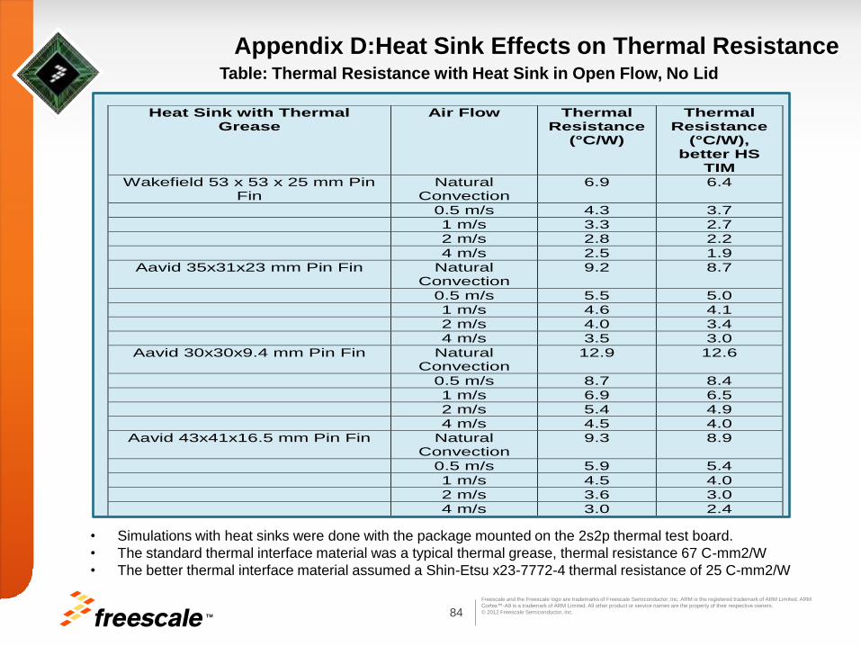
TM 84
Freescale and the Freescale logo are trademarks of Freescale Semiconductor, Inc. ARM is the registered trademark of ARM Limited. ARM
Cortex™-A9 is a trademark of ARM Limited. All other product or service names are the property of their respective owners.
© 2012 Freescale Semiconductor, Inc.
Appendix D:Heat Sink Effects on Thermal Resistance Table: Thermal Resistance with Heat Sink in Open Flow, No Lid
• Simulations with heat sinks were done with the package mounted on the 2s2p thermal test board.
• The standard thermal interface material was a typical thermal grease, thermal resistance 67 C-mm2/W
• The better thermal interface material assumed a Shin-Etsu x23-7772-4 thermal resistance of 25 C-mm2/W
Heat Sink with Thermal Grease
Air Flow Thermal Resistance
(°C/W)
Thermal Resistance
(°C/W), better HS
TIM
Wakefield 53 x 53 x 25 mm Pin Fin
Natural Convection
6.9 6.4
0.5 m/s 4.3 3.7
1 m/s 3.3 2.7
2 m/s 2.8 2.2
4 m/s 2.5 1.9
Aavid 35x31x23 mm Pin Fin Natural Convection
9.2 8.7
0.5 m/s 5.5 5.0
1 m/s 4.6 4.1
2 m/s 4.0 3.4
4 m/s 3.5 3.0
Aavid 30x30x9.4 mm Pin Fin Natural Convection
12.9 12.6
0.5 m/s 8.7 8.4
1 m/s 6.9 6.5
2 m/s 5.4 4.9
4 m/s 4.5 4.0
Aavid 43x41x16.5 mm Pin Fin Natural Convection
9.3 8.9
0.5 m/s 5.9 5.4
1 m/s 4.5 4.0
2 m/s 3.6 3.0
4 m/s 3.0 2.4

85 TM
Freescale and the Freescale logo are trademarks of Freescale Semiconductor, Inc. ARM is the registered trademark of ARM Limited. ARM
Cortex™-A9 is a trademark of ARM Limited. All other product or service names are the property of their respective owners.
© 2012 Freescale Semiconductor, Inc.
Appendix E Thermal Heat Spreader Example
• Teardown Photos: RIM Playback
• Source: http://www.ifixit.com/Teardown/BlackBerry-PlayBook-Teardown/5265/1#.T8kAB1KRMgc
CPU/Memory
Complex
Graphite heat
spreader used to
Cool CPU and
Memory
Graphite Heat spreader
Easily cut into any dimension to
spread heat into other components
Graphite heat
spreader used to
Shield heat from
reaching the
back cover

86 TM
Freescale and the Freescale logo are trademarks of Freescale Semiconductor, Inc. ARM is the registered trademark of ARM Limited. ARM
Cortex™-A9 is a trademark of ARM Limited. All other product or service names are the property of their respective owners.
© 2012 Freescale Semiconductor, Inc.
• Teardown Photos: Kindle Fire
• Source: http://www.ifixit.com/Teardown/Kindle-Fire-Teardown/7099/1#.T8kCmlKRMgf
• Source: http://www.youtube.com/watch?v=MGLn1TVAITQ
CPU/Memory
Complex
Shield and thermal
contact
Metal sheet (heat
spreader and rigidity).
Direct contact with
CPU’s metal shield
Thermal gap
filler
underneath the
processor
Appendix E Thermal Heat Spreader Example
Graphite heat
spreader used to
evenly spread
heat over LCD
display

87 TM
Freescale and the Freescale logo are trademarks of Freescale Semiconductor, Inc. ARM is the registered trademark of ARM Limited. ARM
Cortex™-A9 is a trademark of ARM Limited. All other product or service names are the property of their respective owners.
© 2012 Freescale Semiconductor, Inc.
Appendix E Thermal Heat Spreader Example
• Teardown Photos: Apple iPAD3
• Source: http://www.ifixit.com/Teardown/iPad-3-4G-Teardown/8277/3
CPU/Memory
Complex EMI
Shield
CPU/Memory
Complex
EMI shield is in direct contact
with back of device. Thus acts
as EMI as well as thermal spreader

TM 88
Freescale and the Freescale logo are trademarks of Freescale Semiconductor, Inc. ARM is the registered trademark of ARM Limited. ARM
Cortex™-A9 is a trademark of ARM Limited. All other product or service names are the property of their respective owners.
© 2012 Freescale Semiconductor, Inc.
Two aluminum heat spreaders, one coupled to a lower case made of die cast magnesium alloy,
the other to an upper case of ABS plastic, were used to cool a processor by natural convection only.
Thermally conductive silicon gap pads were used to conduct heat from the microprocessor and
PCB to the rigid aluminum heat spreaders. One disadvantage of this design was that the case
touch temperature immediately below the heat source was high.
The following modifications improved the systems thermal management:
Replacement of the rigid aluminum spreaders with flexible graphite heat spreaders
Thermally insulating elastomeric materials were placed between the graphite and the case and
were used to press the graphite against the heat source.
The anisotropy of the graphite, combined with the insulation of the elastomer, eliminated the
hot spot on the case beneath the processor heat source
The spreader was designed to lie on top of the components and held in place by the contact
pressure generated by the case
The temperature gradient in the hardware components was significantly modified by the
spreaders. The graphite spreaders transferred heat from the hottest component into the
cooler surrounding components.
Increasing either spreader thickness or in-plane thermal conductivity further improved the heat
flow and reduced the overall temperature gradient in the components
Appendix F Thermal Management Technique : Case Study 6
TM 89
Freescale and the Freescale logo are trademarks of Freescale Semiconductor, Inc. ARM is the registered trademark of ARM Limited. ARM
Cortex™-A9 is a trademark of ARM Limited. All other product or service names are the property of their respective owners.
© 2012 Freescale Semiconductor, Inc.
References
1. G. Allan, Embedded DDR Interfaces - Ten Tips to Success for Your SoC, Synopsys Inc. White paper, Sept 2009
2. R. Mahajan, G. Chrysler, C. Chiu, Cooling a Microprocessor Chip, Proceedings of the IEEE | Vol. 94, No. 8, August
2006
3. Yin Xiong; Smalc, M.; Norley, J.; Chang, J.; Mayer, H.; , "Thermal tests and analysis of thin graphite heat spreader
for hot spot reduction in handheld devices," Thermal and Thermo-mechanical Phenomena in Electronic Systems,
2008. ITHERM 2008. 11th Intersociety Conference on , vol., no., pp.583-590, 28-31 May 2008
4. Sung-won Moon; Prstic, S.; Chia-pin Chiu; , "Thermal management of a stacked-die package in a handheld
electronic device using passive solutions," Thermal and Thermo-mechanical Phenomena in Electronics Systems,
2006. ITHERM '06. vol., no., pp.791-797
5. Joiner, B.; Montes de Oca, T.; , "Thermal performance of flip chip ball grid array packages," Semiconductor
Thermal Measurement and Management, 2002. Eighteenth Annual IEEE Symposium , vol., no., pp.50-56, 12-14
March 2002
6. M Smalc et. al, Thermal Performance of natural graphite heat spreaders, Proceedings of IPACK2005, July 17-22,
San Francisco, California USA
7. Technical Data Sheet 486, SPREADERSHIELD-FLXTM Heat Spreaders, GrafTech International Holdings Inc.
8. AN4509 i.MX 6Dual/6Quad Power Consumption, Freescale Semiconductor, Inc., 2012.
9. EIA/JESD51-6, “Integrated Circuit Thermal Test Method Environmental Conditions Forced Convection (Moving
Air),” Electronic Industries Association, July 2000, Arlington, VA, http://www.jedec.org.
10. EIA/JESD51-8, “Integrated Circuits Thermal Test Method Environment Conditions -- Junction-to-Board, "October
1999, http://www.jedec.org.
11. EIA/JESD51-2, “Integrated Circuits Thermal Test Method Environment Conditions – Natural Convection (Still Air),”
December 1995. http://www.jedec.org

TM 90
Freescale and the Freescale logo are trademarks of Freescale Semiconductor, Inc. ARM is the registered trademark of ARM Limited. ARM
Cortex™-A9 is a trademark of ARM Limited. All other product or service names are the property of their respective owners.
© 2012 Freescale Semiconductor, Inc.
Information in this document is provided solely to enable system and software implementers to use Freescale
Semiconductor products. There are no express or implied copyright licenses granted hereunder to design or
fabricate any integrated circuits or integrated circuits based on the information in this document.
Freescale Semiconductor reserves the right to make changes without further notice to any products herein.
Freescale Semiconductor makes no warranty, representation or guarantee regarding the suitability of its products
for any particular purpose, nor does Freescale Semiconductor assume any liability arising out of the application or
use of any product or circuit, and specifically disclaims any and all liability, including without limitation
consequential or incidental damages. “Typical” parameters that may be provided in Freescale Semiconductor data
sheets and/or specifications can and do vary in different applications and actual performance may vary over time.
All operating parameters, including “Typicals”, must be validated for each customer application by customer’s
technical experts. Freescale Semiconductor does not convey any license under its patent rights nor the rights of
others. Freescale Semiconductor products are not designed, intended, or authorized for use as components in
systems intended for surgical implant into the body, or other applications intended to support or sustain life, or for
any other application in which the failure of the Freescale Semiconductor product could create a situation where
personal injury or death may occur. Should Buyer purchase or use Freescale Semiconductor products for any
such unintended or unauthorized application, Buyer shall indemnify and hold Freescale Semiconductor and its
officers, employees, subsidiaries, affiliates, and distributors harmless against all claims, costs, damages, and
expenses, and reasonable attorney fees arising out of, directly or indirectly, any claim of personal injury or death
associated with such unintended or unauthorized use, even if such claim alleges that Freescale Semiconductor
was negligent regarding the design or manufacture of the part.
Freescale™ and the Freescale logo are trademarks of Freescale Semiconductor, Inc. All other product or service
names are the property of their respective owners. ARM is the registered trademark of ARM Limited. ARM
CortexTM-A9 is a trademark of ARM Limited.
© Freescale Semiconductor, Inc. 2012. All rights reserved.


