Embed Size (px)
Citation preview
AN002: BENEFITS AND USE OF LIFI™ LIGHT SOURCES FOR TECHNICAL LIGHTING
Published 2/11/2008
Table of Contents
Abstract........................................................................ 2
Applications ................................................................. 2
The LIFI™Advantage..................................................... 2
Summary of LIFI™ Construction................................... 2
Optical Considerations................................................. 3
Focal Position........................................................... 3
Back Reflections....................................................... 3
Spectrum.................................................................. 3
Light Collection ........................................................ 4
Self Calibration......................................................... 5
Mechanical and Thermal Considerations .................... 5
Mounting and Alignment......................................... 5
Thermal Management ............................................. 6
Electrical Interface ....................................................... 7
LIFI™ GUI .................................................................. 7
UART Communication.............................................. 8
Summary...................................................................... 8
About LUXIM................................................................ 8
ABSTRACT
This document describes the use of Luxim’s LIFI™ light
sources in technical lighting applications. It is intended to provide design guidelines for use of LIFI™ in
instrumentation, visualization, inspection and UV curing equipment.
APPLICATIONS
Luxim offers three unique products for use in technical lighting. LIFI4KP is intended for visible light applications including endoscopy, general microscopy,
machine vision, and inspection. LIFI4KT is a broadband source that includes both UVA and visible region of the
spectrum for fluorescence microscopy applications. LIFI4KU is a mercury source with strong spectral
emission lines down to 320 nm for UV curing, fluorescence imaging, and UV printing. Please refer to
the respective product specifications for technical details.
THE LIFI™ADVANTAGE
LIFI™ is a high intensity light source of revolutionary design. Its hybrid nature combines the efficiency and reliability of solid state lighting with the brightness and
broadband characteristics of HID sources. Luxim uses a patented electrode‐less technology driven by a solid
state RF (radio frequency) amplifier to eliminate the primary degradation mechanism associated with HID
lamps. Without electrodes in its design, LIFI™ can offer extremely long life and unprecedented reliability
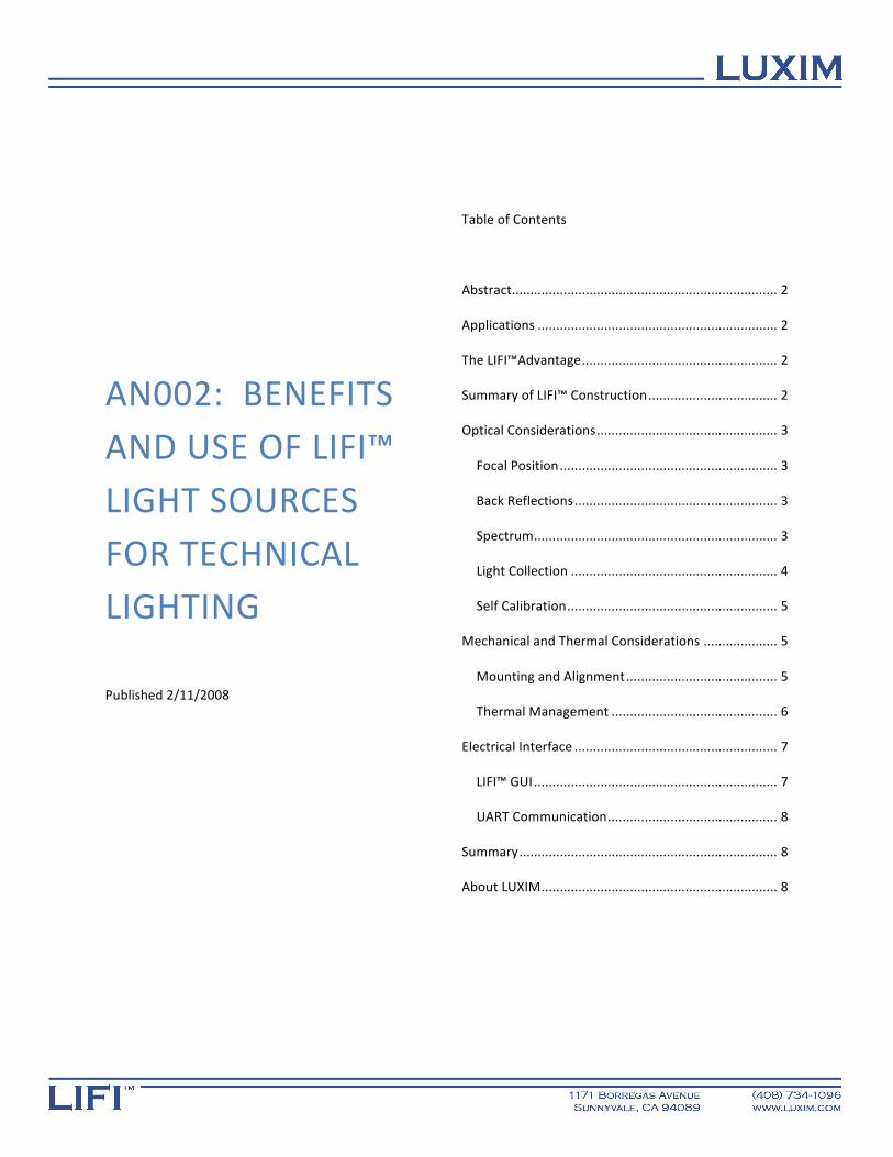
in technical lighting applications (see figure 1 for a typical brightness maintenance plot). This is a lifetime
advantage of more than 10x compared with xenon and short arc mercury sources used in technical lighting
applications.
Figure 1: Typical brightness maintenance curve for LIFI4KP and LIFI4KT
LIFI™ has been engineered to provide many other
benefits for technical lighting including:
• Full spectrum with very high CRI (>90) • High brightness • Ultra low noise and flicker (<0.5% RMS
deviation) • Instant turn on (typical 10 s) • Self calibration capability • Ease of integration and thermal management • Dimming capability with digital
communication
SUMMARY OF LIFI™ CONSTRUCTION
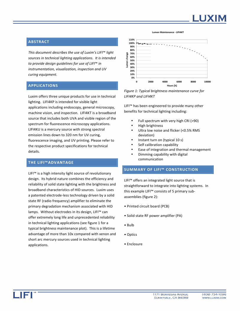
LIFI™ offers an integrated light source that is straightforward to integrate into lighting systems. In this example LIFI™ consists of 5 primary sub‐
assemblies (figure 2):
• Printed circuit board (PCB)
• Solid state RF power amplifier (PA)
• Bulb
• Optics
• Enclosure
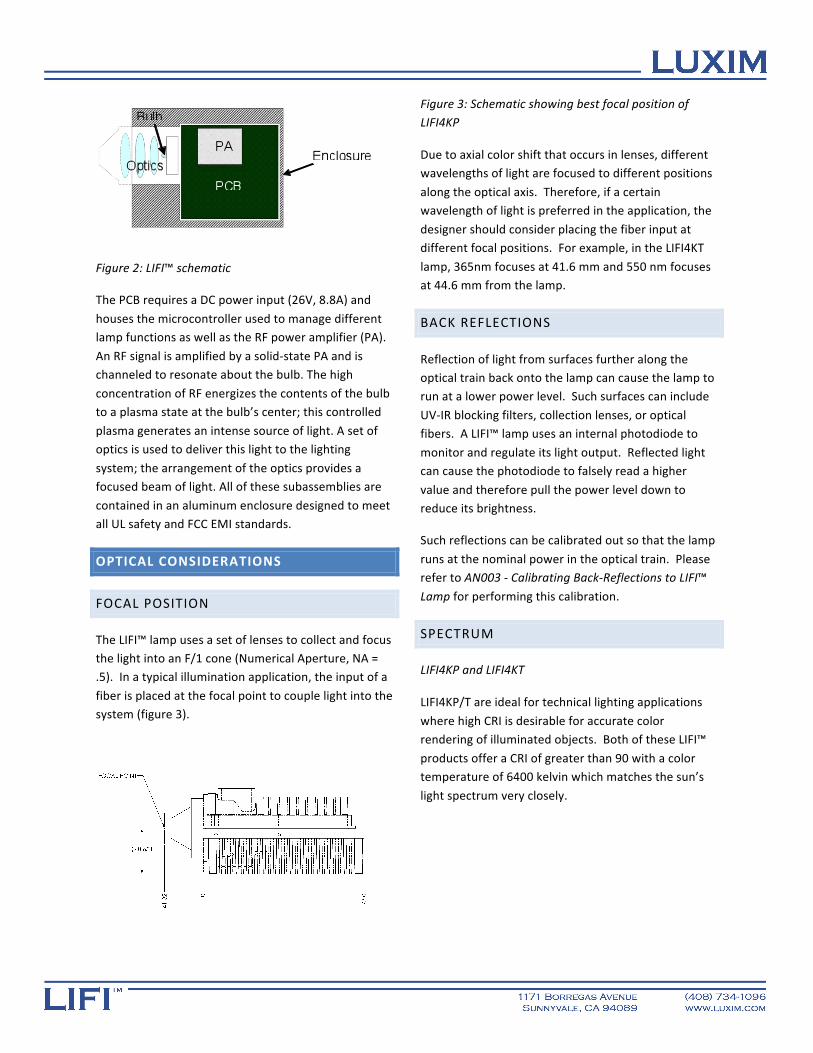
Figure 2: LIFI™ schematic
The PCB requires a DC power input (26V, 8.8A) and
houses the microcontroller used to manage different lamp functions as well as the RF power amplifier (PA).
An RF signal is amplified by a solid‐state PA and is channeled to resonate about the bulb. The high
concentration of RF energizes the contents of the bulb to a plasma state at the bulb’s center; this controlled
plasma generates an intense source of light. A set of optics is used to deliver this light to the lighting
system; the arrangement of the optics provides a focused beam of light. All of these subassemblies are
contained in an aluminum enclosure designed to meet all UL safety and FCC EMI standards.
OPTICAL CONSIDERATIONS
FOCAL POSITION
The LIFI™ lamp uses a set of lenses to collect and focus the light into an F/1 cone (Numerical Aperture, NA = .5). In a typical illumination application, the input of a
fiber is placed at the focal point to couple light into the system (figure 3).
Figure 3: Schematic showing best focal position of LIFI4KP
Due to axial color shift that occurs in lenses, different wavelengths of light are focused to different positions
along the optical axis. Therefore, if a certain wavelength of light is preferred in the application, the
designer should consider placing the fiber input at different focal positions. For example, in the LIFI4KT
lamp, 365nm focuses at 41.6 mm and 550 nm focuses at 44.6 mm from the lamp.
BACK REFLECTIONS
Reflection of light from surfaces further along the optical train back onto the lamp can cause the lamp to run at a lower power level. Such surfaces can include
UV‐IR blocking filters, collection lenses, or optical fibers. A LIFI™ lamp uses an internal photodiode to
monitor and regulate its light output. Reflected light can cause the photodiode to falsely read a higher
value and therefore pull the power level down to reduce its brightness.
Such reflections can be calibrated out so that the lamp
runs at the nominal power in the optical train. Please refer to AN003 ‐ Calibrating Back‐Reflections to LIFI™
Lamp for performing this calibration.
SPECTRUM
LIFI4KP and LIFI4KT
LIFI4KP/T are ideal for technical lighting applications
where high CRI is desirable for accurate color rendering of illuminated objects. Both of these LIFI™
products offer a CRI of greater than 90 with a color temperature of 6400 kelvin which matches the sun’s
light spectrum very closely.
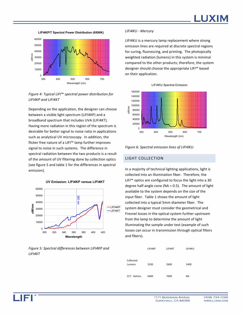
Figure 4: Typical LIFI™ spectral power distribution for LIFI4KP and LIFI4KT
Depending on the application, the designer can choose
between a visible light spectrum (LIFI4KP) and a broadband spectrum that includes UVA (LIFI4KT).
Having more radiation in this region of the spectrum is desirable for better signal to noise ratio in applications
such as analytical UV microscopy. In addition, the flicker free nature of a LIFI™ lamp further improves
signal to noise in such systems. The difference in spectral radiation between the two products is a result
of the amount of UV filtering done by collection optics (see figure 5 and table 1 for the differences in spectral
emission).
Figure 5: Spectral differences between LIFI4KP and LIFI4KT
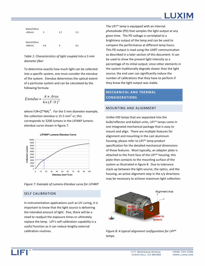
LIFI4KU ‐ Mercury
LIFI4KU is a mercury lamp replacement where strong
emission lines are required at discrete spectral regions for curing, fluorescing, and printing. The photopically
weighted radiation (lumens) in this system is minimal compared to the other products; therefore, the system
designer should choose the appropriate LIFI™ based on their application.
Figure 6: Spectral emission lines of LIFI4KU.
LIGHT COLLECTION
In a majority of technical lighting applications, light is collected into an illumination fiber. Therefore, the
LIFI™ optics are configured to focus the light into a 30 degree half‐angle cone (NA = 0.5). The amount of light
available to the system depends on the size of the input fiber. Table 1 shows the amount of light
collected into a typical 5mm diameter fiber. The system designer must consider the geometrical and
Fresnel losses in the optical system further upstream from the lamp to determine the amount of light
illuminating the sample under test (example of such losses can occur in transmission through optical filters
and fibers).
LIFI4KP LIFI4KT LIFI4KU
Collected Lumens 3100 2600 1400
CCT ‐ Kelvins 6400 7000 NA
Watts(320nm‐450nm) 3 3.7 5.5
Watts(320nm‐600nm) 9.8 9 8.2
Table 1: Characteristics of light coupled into a 5 mm
diameter fiber
To determine exactly how much light can be collected into a specific system, one must consider the etendue
of the system. Etendue determines the optical extent of a particular system and can be calculated by the
following formula:
where F/#=(2*NA)‐1. For the 5 mm diameter example, the collection etendue is 15.5 mm2‐sr; this
corresponds to 3200 lumens in the LIFI4KP lumens‐etendue curve shown in figure 7.
Figure 7: Example of Lumens‐Etendue curve for LIFI4KP
SELF CALIBRATION
In instrumentation applications such as UV curing, it is important to know that the light source is delivering the intended amount of light. Else, there will be a
need to readjust the exposure times or ultimately replace the lamp. LIFI’s self calibration capability is a
useful function as it can reduce lengthy external calibration routines.
The LIFI™ lamp is equipped with an internal photodiode (PD) that samples the light output at any
given time. The PD voltage is correlated to a brightness output of the lamp and can be used to
compare the performance at different lamp hours. This PD output is read using the UART communication
as described in a later section of this document. It can be used to show the present light intensity as a
percentage of its initial output; since other elements in the system traditionally degrade slower than the light
source, the end user can significantly reduce the number of calibrations that they have to perform if
they knew the light output was stable.
MECHANICAL AND THERMAL
CONSIDERATIONS
MOUNTING AND ALIGNMENT
Unlike HID lamps that are separated into the bulb/reflector and ballast units, LIFI™ lamps come in one integrated mechanical package that is easy to
mount and align. There are multiple features for alignment and mounting in the cast aluminum
housing; please refer to LIFI™ lamp product specification for the detailed mechanical dimensions
of these features. Most typically, an adapter plate is attached to the front face of the LIFI™ housing; this
plate then contacts to the mounting surface of the system as illustrated in figure 8. Due to tolerance
stack‐up between the light‐source, the optics, and the housing, an active alignment step in the x/y directions
may be necessary to achieve maximum light collection.
Figure 8: A typical alignment configuration for LIFI™
lamps.

THERMAL MANAGEMENT
There are two components of the lamp that require active cooling: the power amplifier and the bulb. See
figure 9 for a typical approach to cooling the LIFI™ unit.
Figure 9: Typical thermal solution for LIFI™ lamps.
Figure 10: Arrow pointing to the external temperature test point and the PA thermal reference point
The PA is heat‐sunk to the lamp housing and can be cooled by channeling air across its fins. For long term
reliability of the PA, the lamp’s internal temperature sensor must be kept below 76 C (this temperature is
correlated to a PA reference temperature of 80C which is considered a safe operating limit). The internal
temperature sensor can be read using the LIFI™ GUI as described in the next section or via UART queries as
outlined in appendix A of the product specification. If you do not wish to use the electronic communication
function of LIFI™, you can monitor the external test point (shown in figure 10) using a thermocouple. This
temperature is correlated to the internal sensor temperature and also must be kept below 76 C.
The quartz bulb also requires forced air cooling using a blower fan. There is an opening vent in the LIFI™
housing that exposes the bulb for this purpose. The bulb temperature must be kept below a safe limit of
850 C during the operation of the lamp. Unfortunately, due to the size and location of the bulb,
its temperature cannot easily be measured in‐situ. Therefore, Luxim offers customers design guidelines
and validation services for the bulb cooling solution during the prototype design cycle.
Example 1: Cooling the PA
Using the cooling configuration shown in figure 9 as an
example, we can generate system curves needed to specify the fans that can adequately cool the lamp and
the PA housed within it.
Figure 11: System curve showing the required CFM to cool the lamp housing.
Assuming an ambient temperature of 45C, the thermal analysis shows that at least 20 CFM of airflow is
required to cool the PA to a sufficient level. The system curve in figure 11 suggests that a fan must be
chosen that can provide at least 20 CFM of air across a 10 Pa pressure drop. You can see from the
manufacturer supplied fan curve (figure 12) that a Panaflo FBA12G24L provides more than adequate
airflow at 10.2 V (~25CFM/10 Pa). The choice of fan
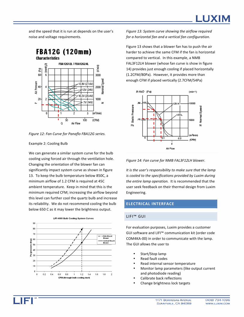
and the speed that it is run at depends on the user’s noise and voltage requirements.
Figure 12: Fan Curve for Panaflo FBA12G series.
Example 2: Cooling Bulb
We can generate a similar system curve for the bulb cooling using forced air through the ventilation hole.
Changing the orientation of the blower fan can significantly impact system curve as shown in figure
13. To keep the bulb temperature below 850C, a minimum airflow of 1.2 CFM is required at 45C
ambient temperature. Keep in mind that this is the minimum required CFM; increasing the airflow beyond
this level can further cool the quartz bulb and increase its reliability. We do not recommend cooling the bulb
below 650 C as it may lower the brightness output.
Figure 13: System curve showing the airflow required for a horizontal fan and a vertical fan configuration.
Figure 13 shows that a blower fan has to push the air harder to achieve the same CFM if the fan is horizontal
compared to vertical. In this example, a NMB FAL3F12LH blower (whose fan curve is show in figure
14) provides just enough cooling if placed horizontally (1.2CFM/80Pa). However, it provides more than
enough CFM if placed vertically (2.7CFM/54Pa)
Figure 14: Fan curve for NMB FAL3F12LH blower.
It is the user’s responsibility to make sure that the lamp is cooled to the specifications provided by Luxim during
the entire lamp operation. It is recommended that the user seek feedback on their thermal design from Luxim
Engineering.
ELECTRICAL INTERFACE
LIFI™ GUI
For evaluation purposes, Luxim provides a customer GUI software and LIFI™ communication kit (order code
COM4KA‐00) in order to communicate with the lamp. The GUI allows the user to
• Start/Stop lamp • Read fault codes • Read internal sensor temperature • Monitor lamp parameters (like output current
and photodiode reading) • Calibrate back reflections • Change brightness lock targets
• Test discrete dimming levels.
Please refer to AN004‐LIFI Customer GUI Instructions for more information.
UART COMMUNICATION
For communication with a LIFI™ lamp in the end system, appendix A of the product specification contains detailed instruction for UART communication.
The UART protocol is designed for a high speed (19,200 Baud Rate), digital communication to control
all features of the lamp. Using this protocol, the system integrator can take full advantage of all LIFI™
features in technical and instrumentation lighting.
SUMMARY
As described in this application note, the LIFI™ models LIFI4KP‐F1, LIFI4KT‐F1, and LIFI4KU‐F1 offers a bright,
full‐spectrum and UV light source for technical lighting. The reliability, functionality and simplicity of
integration of LIFI™ have definite advantages over other light source technologies including HID lamps
and LED’s. LIFI™ brings Light Fidelity™ to technical lighting applications with extreme light stability,
unprecedented reliability and instant turn‐on times. See the LUXIM website (www.LUXIM.com) or contact a
LUXIM sales or applications representative for more information.
LIFI™ and Light Fidelity™ are trademarks of LUXIM
Corporation
ABOUT LUXIM
LUXIM designs, develops and manufactures high
intensity LIFI™ light sources. LIFI™ technology offers the benefits of long‐life, energy efficiency and full
color spectrum to general and specialty lighting. LUXIM is a privately held company based in Silicon Valley California. LUXIM’s investors include Sequoia
Capital, Crosslink Capital and Worldview Technology Partners.
LUXIM Corporation
1171 Borregas Avenue
Sunnyvale, CA 94089
Tel: +1‐408‐734‐1096
Email: [email protected]